INSTALLATION, OPERATION, MAINTENANCE MANUAL KEEP THE MANUAL NEAR THE MACHINE ALL TIME AND MAKE SURE ALL USERS HAVE REAP THIS WHEEL BALANCER .· . . FOLLOW THE INSTRUCTIONS CAREFULLY TO GRANT THE MACHINE A CORRECT FUNCTION AND LONG

Welcome message from author
This document is posted to help you gain knowledge. Please leave a comment to let me know what you think about it! Share it to your friends and learn new things together.
Transcript

INSTALLATION, OPERATION, MAINTENANCE MANUAL
KEEP THE MANUAL NEAR THE MACHINE ALL TIME
AND MAKE SURE ALL USERS HAVE REAP THIS
WHEEL BALANCER
. · . .
FOLLOW THE INSTRUCTIONS CAREFULLY TO GRANT
THE MACHINE A CORRECT FUNCTION AND LONG

Table of Contents
1, SAFETY INSTRUCTIONS ......................................................................................... 1
2, PRODUCT INSTRUCTION ........................................................................................ 1
2.1 EXTERNAL STRUCTURAL DRAWING........................................................................... 1
2.2 FUNCTIONS ................................................................................................................ 2
2.3 SPECIFICATIONS ........................................................................................................ 2
3, TRANSPORTATION ................................................................................................ 3
4,. OPENING PACKAGE ................................................................................................ 3
5, MACHINE INSTALLATION ..................................................................................... 3
5.1 LOCATION .... ........ ........................ ................................... ........................................... 3
5.2 INSTALLING PARTS ..................................................................................................... 4
5.3 POWER CONNECTION ................................................................................................ 4
6" CONTROL UNIT .......................... , .............................................................................. 4
7, OPERATING INSTRUCTIONS ................................................................................. 5
7.1 SELF-CHECK ............................................................................................................. 5
7.2 INST ALLING WHEEL .............................................................................................. 5
7.3 WHEEL PARAMETERS INPUT ............................................................................... 6
7.4 CHOOSE BALANCE MODES .................................................................................. 7
7.5 STANDARD DYNAMIC MODE ............................................................................... 7
7.6 STATIC MODE .......................................................................................................... 8
7.7 ALU1----ALU3 MODES .......................................................................................... 9
7.8 ALUS MODE ........................................................................................................ 1 0
7.8.l ALUS CORRECTION PLANE CHOOSING ...................................................... 1 0

Whee 1 Balance
7.8_.2 ALUS _MODE-OPERATION ...................... u .. u ..... _ ......... -....................... ,.-,uu,, ....... l 0
7;9 OPT ·-FUNCTION ,o,-�•uo-,,,,, .. ,,,,uu .. , ... Hou,,,,,.,,HHH>!H•�� .... +,,,,,,,o,,.,,,oouuHu,i,,,�,,,., .. ·_l · ·1
7,.10 SYSTE,M_-SETTJNG,u,u+•,o•••••••••uou,_uoH,H<H .. 0-!''''-''''''HHOIHUUHnuu,,,,,,. .. .,, .. ,onou,,, 1- 2
1 .. 11·_cALIBRATION PR_OGRAM_S ..• H,., ........ .-�; .............................. ,uu ........... _ ........ u .. 1 -2
8 ERROR INFORMATION AND TREATMENT, ............. , ...................................... ,. 1 4
·APPENDJ:X.-J H•HHn•+•••••••••••••Hu,,oHHuo,,, .. ,,,,o,,,un,u,,·uuHouu,,o,,i,uu,,,uu,,,,,,,,..,,,,,.._,,,u, 1 5
APPENJ)J:X ··II; .... ,,,ouu,o,,uu••·;,.,,,,,,, .. ,,,.,,u,n>,, .. ,.,.,,.,.,,-,,1.,,u .. ,,.,,,,,.,.,.,,,,ouo,,,,,,uu,; .. ,, .. , -1 6
APPENDIX III ,u .... , .......... ,.,u ............ _;p .. ,, ... ,,u ... u ... , •••• � ............ , ......................... ,u•••····· 1 7
APPENDIX IV ................... .-...••. ,,,,u,, ....... ,.,uu,�u,,,u .. , ........................ ,uu .. ,, ................... _ 1 7
Wheel Balance
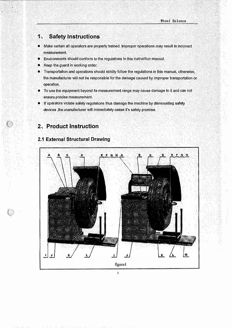
1, Safety Instructions
• Mak.e certain all operators are properly trained. Improper operations may result in incorrect
measurement.
• Environments. should conform tolhe regulations In this instrucUon manual.
• Keep the guard in working order.
• Transporlalion and operations should stricUy follow the reg!llations in this manual, otherwise,
the manufacturer wlll not be responsible for the damage caused by Improper transportation or
operation.
• To use the. eqµlpment beyond Its measurement range may cause damage to it and can not
ensure precise measurement.
• If operators violate safety regulations thus damagethe machine by dismounting saf,;ty
devices ,the manufacturer will immediately ce;ise it's safety promise.
2, Product Instruction
2.1 External Struct1Aral Drawing
figure I

Wheel Balance
A. Operation Panel
C. A value Manual Gauge
E. Shaft
B. Counterweight Container
D. Safety Guard
G. Special Cone
I. Power Switch
K. Pneumatic Elevator
M. Pneumatic Elevator Switch
2.2 Functions
• Dynamic Mode
• Static Mode
• Sta11dard ALU I, ALU2, ALU3, Mode
• ALUSMode
• OPT(OPTIMIZATION) mode
• Truck /Car Measurement Mode Shift
• Unit Conversion in Different Countries (Areas)
g/ oz, mm/ inch
• Self-calibration
• Guard Protection
• Self-check Error and Diagnostics
• Computer controlled wheel pneumatic elevation
• Chain protection of elevation process. ( CB-1280)
F. Threaded End
H, Lock Hub Nut and Lever
J, Balancer Body
L. Sliding Car
• Pneumatic brake fixed start lock, and auto unlock for measurement. again.
• Patent technology of pneumatic control friction wheel drive separation system, improve measurement
accuracy. ( CB-1280)
2.3 Specifications
• f!l.il!!f!l.Jli, Single Phase Power Supply: 220V I 50 Hz or 110V I 60 Hz
3-Phase Power Supply :380 VI 50 Hz !i.'i; 220 V / 60 Hz
• Air pressure, 0.4,0.8MPa
• Protection Class: IP 54
• Power Consumption: 260w
• Max Rotating Speed: 180 r Im in ( car)
90 r/min (truck)
• Cycle Time: Average 8-14s
• Measurement Ranges:
Gauge length 10 -·· 300mm
2

Rim Diameter: 10" � .•. 30''
WheelWidth: 1.6" ....c 20"
Wheel Diameter: < 1200 mm Wheel weight, <160kg
• Error, �±1g 0.1oz <can
s;;±10g 0.35oz <truck>
• Noise: s;;1odB
• Net Weight:280kg. (CB-1200)
350kg (CB01280) • Worl<ing Environment: Temperature: -20'C-50'C, Humidity: ,s,;85%
3, Transportation
The balancer must be transported in .the
original package and be placed in the specified
position.
Use a fo*lift with correspc:mding capacity to
move the packed machine and the direction of
the forklift ls shown in figure 2.
Wheel Balance
Cl;l-1200:
L = 1200 W = 960 H " 1140
CJ:l-1280:
L • 1,so W • 841) H = 1180
figure2
4, Opening Package ·
• Check the package, lflhere are some problems, please do not open it, and contact the
supplier and the carrier at once.
• Make sure that the package is not damage,:! and then open the protection carton and plastic
bag. Check the accessory case according to the packing list. Check whether the machine
surface Is in good cond.ilion and whether there is loss or damage to the parts.• Dismount the. bolts on the base and make the balancer steadily rest.• Please do not use the machine and contact the
supplier at once if there are some problems.
5, Machine Installation
5.1 Location
• The machine must be located in the working
environment described in 2. 3 and the ground CB-1200
figure3
{. .•
Wheel Balance
should be solid.
• Sockets that match the power supply and motor power described in 2. 3 are available nearby
• . Air joints described in 2. 3 are available nearby.
• Space for installing is big enough to meet the needs in figures 3 and 4 and ensures each part
of the machine to work normally.
• Put up a shelter if placed outdoors.
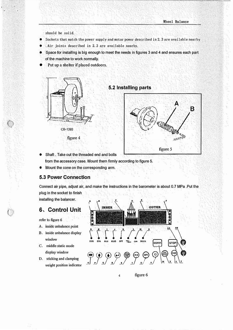
5.2 Installing parts
CB-1280
figure 4
figure 5
• Shaft. Take out the threaded end and bolts
from the accessory case. Mount them firmly according to figure 5.
• Mount the cone on the corresponding arm.
5.3 Power Connection
Connect air pipe, adjust air, and make the instructions in the barometer is about 0.7 MPa .Put the
plug in the socket to finish
installing the balancer.
6, Control Unit
refer to figure 6
A. inside unbalance point
B. inside unbalance display
windo,v
C. middle static mode
display window
D. sticking and clamping
\Veight position indicator
A •
' ttttrtrr OYff STA ALU AlUS OPT '17...:,,i °'" TRIJCll
@@@(.:i)@ee© J_J_JJ_JiJ_J_J
4 figure 6
f

E. outside unbalance display window
F. outside unbalance point
G. standard dynamic mode indicator
H. static 1node indicator
I. ALU mode indicator
J. ALUS mode indicator
K. OPT indicator
L. nun/inch indicator
M. car tnode indicator
N. truck mode indicator
Q. + function key
T. ALU mode key
W. start key
0 . size inpnt shift key
R. Enter key
U . OPT option key
X . truck I car shift key
Wheel Balance
P. -function key
s. dynamic/static key
V. unit shift key
Y. fine display key
Z . Stop/ fixed lock key AA. pneumatic elevator down key AB. pneumatic elevator up key
7, Operating Instructions
7.1 Self-check
When switched on, the system begins self-check
and then enters standard dynamic mode
measurement.(refer to figure 7)
7.2 Installing Wheel
figure 7
Choose the optimal cone for the center hole and mount it on the balancer.(refer to figures 8 and
9). Use the elevator to assist installing if
figure 8
5
the wheel is too heavy.
The method shown in figure 9 is
preferable because it approximates to
installing wheel on a real car.
figure 9

7 .3 Wheel Parameters Input
Unlike ALUS which needs 4
parameters, other modes need
3 parameters.
Parameter values are shown in
figure 10. ( dynamic and static
modes, ALU1-3 mode,
motorcycle mode) Figure 11
<ALUS model
Users can finish the parameters
input manually.
(refer to figure 12, 13)
1.n •dynmniC:�iatic,/',UJ ,nwtorcyctemodes
figure12
Wheel .Balance
figure I 0 figure 11
( ln ALUS mode )
figure 13
6
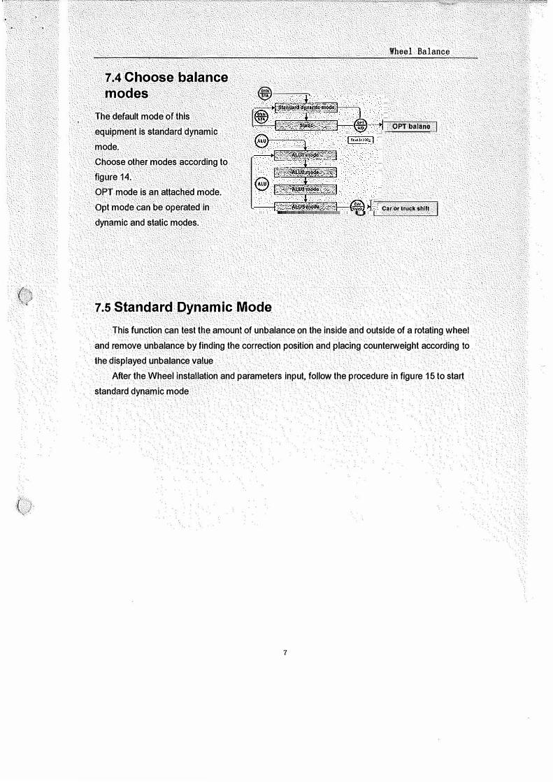
7.4 Choose balance modes
The default mode of this
equipment is standard dynamic
mode.
Choose other modes according to
figure 14.
OPT mode is an attached mode.
Opt mode can be operated in
dynamic and static modes.
@,-
7.5 Standard Dynamic Mode
Wheel Balance
OPTbalane
Car or lruck $hlfl
This function can test the amount of unbalance on the inside and outside of a rotating wheel
and remove unbalance by finding the correction position and placing counterweight according to
the displayed unbalance value
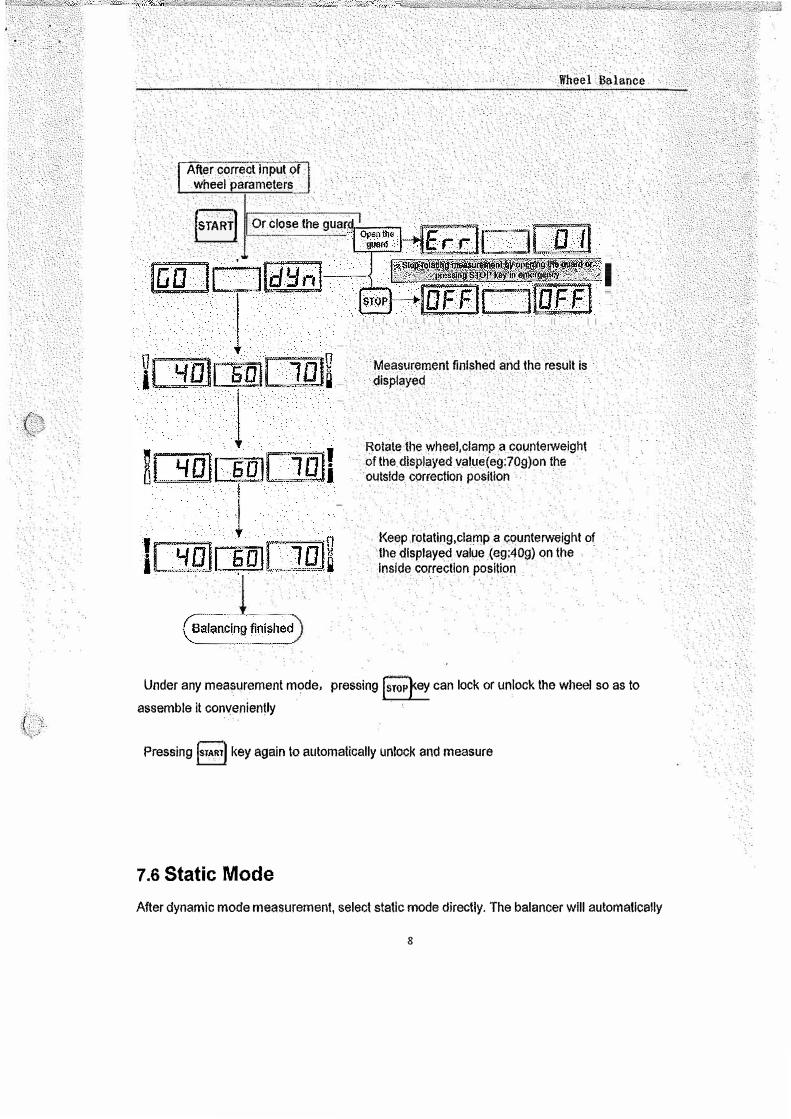
After the Wheel installation and parameters input, follow the procedure in figure 15 to start
standard dynamic mode
7
fMer correct lnp. ul of
l_J,vheel parameters
jsrARTJ Or close the guard
Wheel Balance
Measurement finished and the result is displayed
Rotate the wheel,clamp a counterweight of the. displayed value(eg:70g)on the outside correction position
Keep rotatlng,clamp a ,;:i;>unterweight of the displayed value (eg:40g) on the inside correction position
Under any measurement mode, pressing !srop�ey can lock or unlock the wheel so as to assemble ii conveniently
Pressing !START! key again lo automatically unlock and measure
7.6 Static Mode
After dynamic mode measurement, select static mode directly. The balancer will automatically
8

(
Wheel Balance
calculate the result of static mode.
If static mode is done from the very beginning, follow the process below after wheel installation
and correct parameters input
Alter correct input of wheel parameters
r:::::} I Or close the
t::.:.:J guard
Measurement finished and the result is displayed
Rotate the wheel,clamp a counterweight of the displayed value(eg:60g)on the correction point
Balancing finishec
figure 16
7.7 ALU1----ALU3 Modes
ALU mode refers to five counterweight sticking
modes reduced according to the shapes and
sizes of most rims. ( figure 17)
The measurement process of ALU is the same as
that of standard dynamic mode
After measurement, clamp counterweights at 1
o'clock positions,. At 2, 3 and 4 o'clock position,
9
I.
11111111

Wheel Balance
slick counte,weights according to figure.18.
A special purpose gauge can also be used to 11ssisl in sticking counterweights .
7 .8 ALUS Mode
.
.
.
13nun :
112" • • • : .
.
. •
. .
. .
. .
. .
: : : :
figure 18
Because ALUS inputs the precise size of the correction plane with the aid of
automatic gauge, it compensates for ALU mode that ALU1·3 fail to satisfy, and It is
more accurate and easier than the traditional ALU mode (refer to figure 19)
7.8.1 ALUS Correction Plane
choosing
ALUS has to choose two proper correction
planes on both sides of rim. Clean the position to be
used to get ready for being stuck.
Mount the wheel. and collect parameters
7 .8.2 ALUS Mode Operation
.•
.
. •
.• •
• • • • • • . • • .• • •
,. .
• • • • . . • • • • . .
figure 19
After collecting, close the guard, press START to measure. The process Is the same as that
of standard dynamic mode.
After measurement, the unbalance value Is displayed. Referring to the figure , rotate the wheel to
the outside correction plane position shown by the parameters collected,. stick counterweight at
l 0

(
(
12 o'clock.
7.9 OPT
Function
OPT function is
used to determine the
best mating of tire and
rim. When doing
dynamic and static
modes, if the static
mode value is greater
than OPT value
(implied 30g}, the
system will start
optimization.
When optimization is
'bi ,Rposs1 e, press �
key to operate
according to figure 25.
When optimization is
not possible, display
OFF OPT and exit
OPT operation.
figure 20
I I
Wheel Balance
Press OPT key to start.
Step 1
Rotate the gas nozzle to 12
o'clock. Press ENTER key to
memorize the point. Mark with a
chalk a reference mark on the tire.
Step 2
Remove the wheel from the
balancer using a tire changer.
Align the nozzle and the mark by
rotating the tire on the rim by 180
degrees
Step 3
Replace the wheel on the
balancer and rotate the gas
nozzle to 12 o'clock again.
Press "ENTER" key to memorize.
Step 4
Press START key to start OPT
measurement.
After measurement, mark with
chalk again on the tire the marked
point indicated on the screen.
Using the changer to assemble
until the new mark and the gas
nozzle coincide. Now the value
displayed is the rest value after
optimization.
Press EMTER to end
optimization.
Wheel
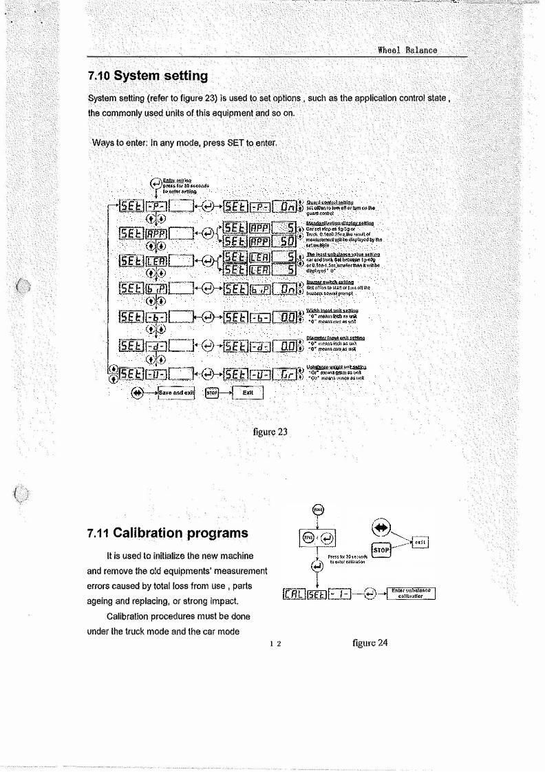
7,10 System setting
System setting (refer to figure 23) is used to. set options , such as the application control state
the i::ommonly used units of.this equipment .and so on.
Ways to enter: In any mode, press SET to enter.
figure 23
7.11 Calibration programs
It is used to initialize the new machine
and remove the old equipments' measurement
errors caused by total loss from use , parts
ageing and replacing, or strong Impact.
Calibralion procedures must be done
under the truck mode and the car mode I 2 figure 24

(
Wheel Balance
respectively. Follow figure 24 to start calibration under either mode.
Choose a wheel with small unbalanced value and install it on the balancer. Input the wheel
parameters then calibrate it as shown in figure 25.
START
IFaT1 GD ".···· .. lh11bJ [fil1J L__l
Finish and return
figure 25
Rotate the wheel to calibrate for the first time without
placing standard counterweight.
Rotate the wheel to calibrate for the second lime by
placing a counterweight of 1 OOg at 12o'clock outside of
rim.
After measurement automatically store the result of
calibration.
After calibration automatically return to the original state.
1 3
Wheel Balance
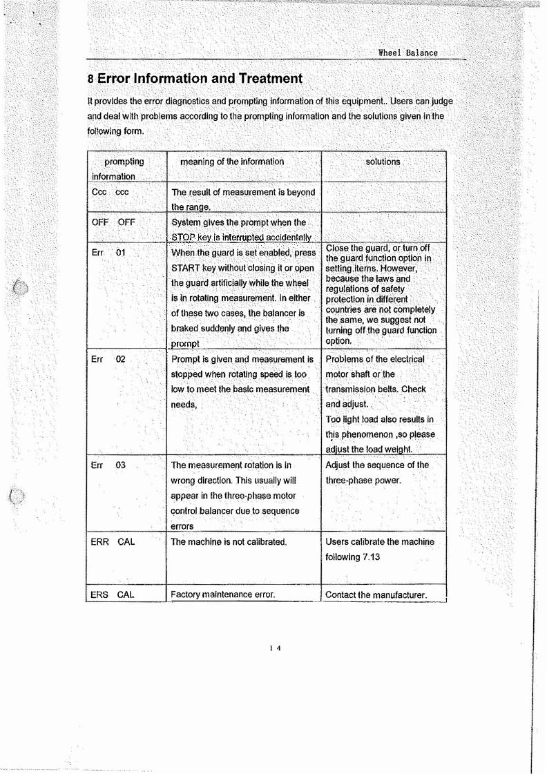
8 Error Information and Treatment
It provides the error diagnostics .and prompting Information of this equipment.Users can judge and deal with problems according to the prompting Information and the solutions given In the following form.
prompting information Ccc CCC
OFF OFF
Err 01
Err 02
Err 03
ERR CAL
ERS CAL
rneanlng of the information
The result of measurement Is beyond the ran e. System gives the prompt when the
When I.he guar<:1 ls set enabled, press START key without closing It or open the guard artificially while the. wheel Is in rotating measurement. In either of these two cases, the balancer is braked suddenly and gives the
Prompt is given ;ind measurement is stopped when rotating speed is too
solution.s
Close the Quard, or turn off the guard function option in setting.items. However, because the laws and regulations of safety protection in different countries are not completely the same. we suggest not turning off the guard function option.
Problems of the electrical motor shaft or the
low to meet the basic measurement transmission belts. Check needs, and adjust.
The measurement rotation Is in wrong direction. This usually will appear in the three-phase motor control balancer due to sequence errors The machine is not calibrated.
Too light load also results in t�is phenomenon ,so please ad'ust the load wel ht. Adjust the sequence of the three-phase power.
Users calibrate the machine following 7 .13
Factory maintena-n_ce-'-er--ro....:r.:_. ___ _._C_on-"t-'-ac....:t..:.th_e_m
.-:a .. n--u __ f_ac_tu_r_e_r. _ _,
1 4
Wheel Balance
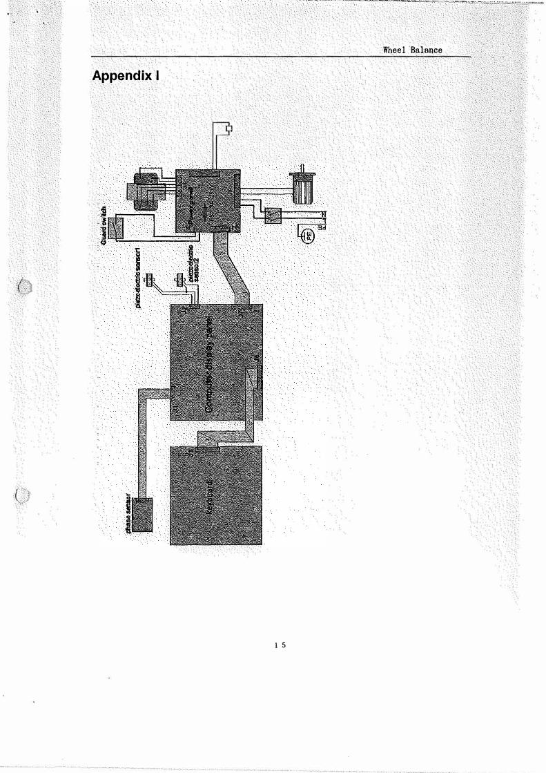
Appendix I
(
l 5
, ______ : _:·ccc."F.C.•:" '
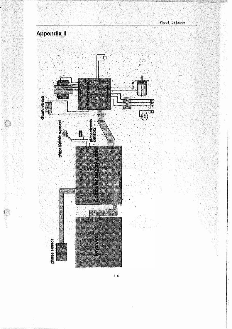
Appendix II
I I
-----�.-· -,"
Wheel Balance
1 6

Appendix 111
I i
Wheel Balance
I 7

Appendix IV
( }
I i
Wheel Balance
1 8
Related Documents