Fulton Ltd J DUAL FUEL MANUAL 02 2014 ISSUE 9 J SERIES - DUAL FUEL STEAM BOILER (Switchable Burner) (including optional Fully Modulating Burner) This manual must be available to the boiler operator at all times. INSTALLATION, OPERATION AND MAINTENANCE MANUAL

Welcome message from author
This document is posted to help you gain knowledge. Please leave a comment to let me know what you think about it! Share it to your friends and learn new things together.
Transcript

Fulton Ltd
J DUAL FUEL MANUAL 02 2014 ISSUE 9
J SERIES - DUAL FUEL STEAM BOILER (Switchable Burner)
(including optional Fully Modulating Burner)
This manual must be available to the boiler operator at all times.
INSTALLATION, OPERATION AND MAINTENANCE MANUAL

J DUAL FUEL MANUAL 02 2014 ISSUE 9
The Pressure System Safety Regulations 2000
Fulton boilers fall within the scope of the Pressure Systems Examination Scheme.Regular inspections are therefore required by a competent person.The scope of the examination and the actual intervals between examinations is at the discretion of the competent person.It is the responsibility of the user to provide a written scheme of examination for those parts of the system in which a defect may give rise to danger.Instructions in this manual are provided for the safe operation and maintenance of the boiler and do not cover periodic statutory inspections.
For further information contact:
(a) SAFed SAFETY ASSESSMENT FEDERATION Limited. Nutmeg House, 60 Gainsford Street, Butlers Wharf, London, SE1 2NY.
(b) Health and Safety Executive local office.
(c) Your Competent Person.
For your safety!The following WARNINGS, CAUTIONS and NOTES appear in various sections of this manual.
WARNINGS must be observed to prevent serious injury or death to personnel.
CAUTIONS must be observed to prevent damage or destruction of equipment or loss of operating effectiveness.
NOTES: must be observed for essential and effective operating procedures, conditions and as a statement to be highlighted.
It is the responsibility and duty of all personnel involved in the operation and maintenance of this equipment to fully understand the WARNINGS, CAUTIONS and NOTES by which hazards are to be eliminated or reduced.
Personnel must become familiar with all aspects ofsafety and equipment prior to operation ormaintenance of the equipment.
CAUTIONIn case of emergency
This boiler has been designed and constructed to meet all of the essential requirements of the applicable European Directives and subject to proper maintenance should not give occasion to any hazardous conditions.
If such a condition should occur during commissioning or during subsequent operation of this product, whatever the cause, then the fuel supply to the boiler should be isolated immediately, until the fault has been investigated
by a competent person and rectified.
WARNINGSteam boilers are a potential hazard, possibly fatal if not properly maintained.
CAUTIONIt is vitally important that the instructions
given in this manual are strictly adhered to.Failure to carry out the routine maintenance
checks could result in a drastic reduction in thelife expectancy of the boiler.
!
!
!
!
!

J DUAL FUEL MANUAL 02 2014 ISSUE 9
LIST OF CONTENTS
INTRODUCTION 1
General 1.1
Technical Data 1.2
INSTALLATION 2
General 2.1
Siting 2.2
Ventilation 2.3
Flue Outlet 2.4
Water Supply (see also section 5.3) 2.5
Blowdown Valves 2.6
Main Steam Valve 2.7
Steam Safety Valves 2.8
Water Level Gauge Set (sight Glass) 2.9
Electrical Requirements 2.10
Gas Supply 2.11
Oil Supply 2.12
Steam Pressure Gauge 2.13
Commissioning the Boiler 2.14
- Boiler Inspection and Initial Firing - Oil 2.14.1
- Boiler Inspection and Initial Firing - Gas 2.14.2
Gas Monoblocs (Non Modulating Burners) 2.15
- Multibloc Gas Valve (Non Modulating Burners) 2.15.1
- Multibloc Gas Valve (Fully Modulating Burner) 2.15.2
Setting The Burner Controls For Fully Modulating Models 30 - 60
2.16
Cleaning Steam Lines and Pressure Vessels 2.17
OPERATION 3
General 3.1
Boiler Controls 3.2
Control Panel - Indicator Lights 3.3
Changing To The Alternative Fuel 3.4
Filling the Boiler - All Models 3.5
Starting the Burner - All Models - Gas 3.6
Starting the Burner - All Models - Oil 3.7
MAINTENANCE 4
Visual Checks 4.1
Water Level and Low Water Safety Controls 4.2
- Pump Test 4.2.1
- 1st Low Water Level Check 4.2.2
- 2nd Low Water Level Check 4.2.3
Main Blowdown 4.3
Water Column Blowdown 4.4
Water Level Gauge Blowdown 4.5
Evapouration Checks 4.6
Flame Sensor Test 4.7
Draining the Boiler 4.8
Long Term Shutdown 4.9
Internal Inspection 4.10
Schedule of Operator Tests and Checks 4.11
- Daily 4.11.1
- Weekly 4.11.2
- Three Monthly 4.11.4
- Six Monthly 4.11.5
- Annually 4.11.6
Troubleshooting 4.12
Maintenance Log 4.13
Daily and Weekly Test Log 4.14
GENERAL DATA 5
Boiler Dimensions 5.1
Boiler Specification 5.2
Recommended Water Conditions 5.3
APPENDIX Optional Variations (where fitted)
Water Level Probe Info A
Motorised High/Low Control B
Spirax High Intensity Level Controls C
Electrical Diagrams (Supplied Separately)

J DUAL FUEL MANUAL 02 2014 ISSUE 9
WARNINGDo not try to do repairs or any other maintenance work you
do not understand. Obtain a service manual from Fulton Ltd or call a Fulton service engineer.
WARNINGIt is the responsibility of the installer to ensure all parts supplied with the boiler are fitted in a correct and safe manner.
WARNINGUnderstand the electrical circuit before connecting or
disconnecting an electrical component. A wrong connection can cause injury and or damage.
WARNINGA defective boiler can injure you or others. Do not operatea boiler which is defective or has missing parts. Make sure
that all maintenance procedures are completed before usingthe boiler.
CAUTIONObey all laws and local regulations which affect you and
your boiler.
WARNINGDo not change the boiler fuel without consulting the boiler
manufacturer.
WARNINGLIFTING EQUIPMENT
Make sure that lifting equipment complies with all local regulations and is suitable for the job. You can be injured if you use faulty lifting equipment. Make sure the lifting
equipment is in good condition.
WARNINGOperating the boiler beyond its design limits can damage the
boiler, it can also be dangerous.Do not operate the boiler outside its limits.
Do not try to upgrade the boiler performance by unapproved modifications.
WARNINGNon-approved modifications can cause injury and damage.
Contact your Fulton dealer before modifying the boiler.
WARNINGOnly qualified persons should be allowed to operate and maintain the boiler and its equipment. Boilers should always be drained through an approved blowdown vessel.
WARNINGThe installation of gas appliances including the flue system
should only be carried out by Gas Safe registered engineers.
SAFETY The instructions provided for the operation and maintenance of the boiler MUST be observed. Failure to do so could result in damage to the boiler and serious personal injury.
!
!
!
!
!
!
!
!
!
!
!
!
!
!
!
!
!
WARNINGDANGER FROM HOT SURFACES
Steam boilers have high temperature surfaces, that if touched may cause serious burns. Only competent and qualified personnel should work on or in the locality of a steam boiler and ancillary equipment. Always ensure the working area and
floor are clear of potential hazards, work slowly and methodically.
Do NOT store inflammable materials near the boiler.
WARNINGDANGER FROM INCOMPLETE COMBUSTION
The importance of correct burner adjustment to achieve lowemissions, safe, clean and efficient combustion is paramount.Poor combustion, where unburnt gas forms carbon monoxide is both a health hazard, and the potential risk to the boiler
from overheating, caused by re-burning of the unburnt gas in the secondary flue passes.
WARNINGThe importance of correct boiler water and feedwater cannot be over emphasised, see the relevant section in this manual.
CAUTIONLOW FEEDWATER TEMPERATURE
Low feedwater temperature can result in thermal shock to the boiler pressure vessel. Return the maximum amount of
condensate and if necessary preheat the feedwater. If in doubt consult Fulton Ltd.
CAUTIONWATER SOFTENER and CHEMICAL TREATMENT
The chemicals required to operate the water softeners andchemical treatment plants CAN BE SUPPLIED by
Fulton Ltd.It is the responsibility of the operator to ensure adequate
supplies of chemical are available at all times (including commissioning).
Costly repairs could be required should the plant operate without chemicals or the wrong dosage of chemicals.
CAUTIONHYDRAULIC TEST - RISK OF BRITTLE FRACTURE
Hydraulic testing requires specialist equipment and is normally only required by engineering surveyors / inspectors.In order to ensure the material/ pressure vessel does not suffer from brittle fracture, hydraulic testing should not be
carried out below 7°C.
WARNINGPrior to the commencement of any work requiring the
removal of cover plates and the opening of control panel box, the electrical supply to the boiler must be isolated.

J DUAL FUEL MANUAL 02 2014 ISSUE 9
TITLE FIG. NO
Typical Dual Fuel Boiler 1
Major Fuel Components 2
Typical Installation 3
Boiler Flue Connection 4
Boiler Feed Water Arrangement 5
Boiler Blowdown (20-60) 6
Boiler Blowdown (6-15) 6A
Boiler Top Components 7
Control Box 8
Gas Supply 9
Oil Supply 10
Steam Pressure Gauge 11
Basic Burner Electrode Settings 12
Feedewater Stop Valve 13
Ignition Flame Detector 14
Main and Primary Air Controls 15
Burner Flame Observation Glass 16
Pressure Controller 17
6J - 30J Gas Valve Major Components (Non-Modulating Burner) 18
6J - 30J Gas Valve Major Components (Fully Modulating Burner) 19
Boiler Operation 20
Alarm and Indicator Lights 21
Boiler Maintenance 22
Pump Interrupt Switch 23
Main Boiler Blowdown Valve 24
Water Column 25
Water Level Gauge Operating Positions 26
Water Level Gauges (Sight Glasses) 27
Flame Sensor Removal 28
Automatic Blowdown Valve 29
Handhole 30
Feedwater Pipe Removal 31
Burner Assembly 32
Flue Cleaning 33
Fault Finding Check List 34
Boiler Dimensions 35
Water Level Probe Components 36
Angle Rajah Fitted To Probe 37
High/Low Control 38
Air Damper Motor 39
Control Panel Side 40
LIST OF ILLUSTRATIONS

J DUAL FUEL MANUAL 02 2014 ISSUE 9Page 6
1
Steam PressureGauge
Oil Pump Motor
Air Pressure Switch
Water Column
Water Level Gauge Sets
Operator Control Panel
Control Box
Door Electrical Isolator
Fuel Selector Switch
Automatic TDS Blowdown
MotorisedHigh / LowControl
Monobloc Gas Train
Steam PressureControllers
FIG. 1 TYPICAL DUAL FUEL BOILER

J DUAL FUEL MANUAL 02 2014 ISSUE 9 Page 7
1
SECTION 1 - INTRODUCTION
The Fulton J Series Dual Fuel Fired Steam Boiler is a vertical two-pass boiler of simple and efficient design and construction. Every care has been taken in the manufacture of the boiler to ensure that quality and reliability standards are maintained. Satisfactory performance can only be ensured if the installation recommendations, operating routines and maintenance schedules laid out in this manual are adhered to. Particular attention should be paid to electrical installation and water treatment.
Dual Fuel boilers are supplied complete with all the components necessary to operate on either Gas or Oil Fuel. The controls are arranged such that the change over from one fuel to another can be achieved by selecting the required fuel on the control panel and isolating the off line fuel supply.
1.1 GENERAL
1.2 TECHNICAL DATA
For a full specification refer to Section 5.
CAUTIONWATER SOFTENER and CHEMICAL TREATMENT
The chemicals required to operate the water softeners and chemical treatment equipment CAN BE SUPPLIED by Fulton Ltd.
It is the responsibility of the operator to ensure adequate supplies of chemical are available at all times (including commissioning).
Costly repairs could be required should the plant operate without chemicals or the wrong dosage of chemicals.
!
J DUAL FUEL MANUAL 02 2014 ISSUE 9Page 8
2
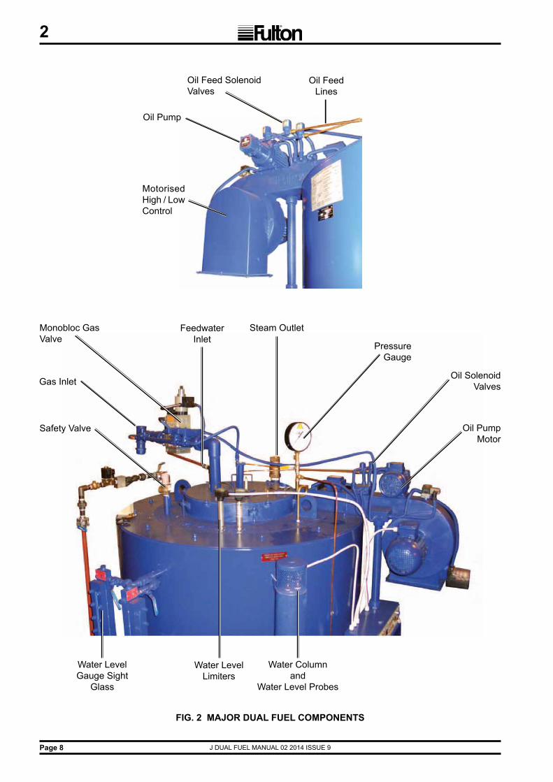
FIG. 2 MAJOR DUAL FUEL COMPONENTS
Monobloc Gas Valve
Gas Inlet
FeedwaterInlet
Steam Outlet
Safety Valve
PressureGauge
Water Level Limiters
Water Level Gauge Sight
Glass
Oil PumpMotor
Oil SolenoidValves
Water Columnand
Water Level Probes
Oil Feed Solenoid Valves
Oil Pump
Motorised High / LowControl
Oil Feed Lines

J DUAL FUEL MANUAL 02 2014 ISSUE 9 Page 9
2
SECTION 2 - INSTALLATION
2.1 GENERAL
2.2 SITING
2.3 VENTILATION
The installation of a J Series Dual Fuel Fired Steam Boiler should be carried out by competent personnel in accordance with all relevant safety regulations. It is the responsibility of the installer to ensure that these regulations are complied with.
The requirements and instructions contained in this section are for boilers being installed to operate on Natural Gas or 35 sec. Fuel Oil.
The flooring must be level, laid in a non-combustible material and be of sufficient strength to support the boiler.
(Reference should be made to Utilisation Procedures as stated in IGE/UP/10 Part 1 Communication 1676, and in particular to Section 5, Location of Appliances).
The boiler house should be sufficiently sized to allow easy and safe access to all parts of the boiler for operational and maintenance purposes.
Reference should be made to Section 5 - General Data to ascertain the relevant dimensions and weights, special note should be taken of the required vertical clearance required for maintenance.
WARNINGMaintenance on the burner assembly requires the area directly aboveand to one side of the boiler must not be obstructed with pipework or
equipment which would interfere with the removal of the complete burnerunit. Care should be taken on installation of the boiler to ensure this
area remains clear of obstructions.
!
Adequate fresh, clean air is necessary for safe and efficient combustion, and should be provided at high and low level in accordance with BS 6644 1991 and IGE/UP/10 Part 1 Communication 1676.
Note:a) Ensure that there is adequate ventilation in the boiler room. Lack of ventilation will create a high
temperature and cause control lockout. There is a minimum ventilation requirement to supply the air for combustion.
b) Do not keep exhaust fans running with windows, doors and vents closed, this will interfere with the necessary boiler draught.
c) Do not store chemicals such as perclorethylene in the boiler house, the fumes may damage the boiler and flue and cause the burner to lock out on flame failure.
Note: see Section 5 for low and high level values.

J DUAL FUEL MANUAL 02 2014 ISSUE 9Page 10
2
FIG. 3 TYPICAL INSTALLATION
STA
ND
AR
D B
OIL
ER
TR
IM S
UP
PLI
ED
WH
EN
OR
DE
RIN
G T
HE
BO
ILE
R
STE
AM
SU
PP
LY
WAT
ER
CO
LUM
NB
LOW
DO
WN
LIN
E
PIP
E S
AFE
TY V
ALV
ETO
SA
FE A
RE
A, F
ITTI
NG
UN
ION
S A
ND
DR
AIN
STO
PVA
LVE
FEE
DW
ATE
RC
HE
CK
VA
LVE
(T
O B
E IN
STA
LLE
D
BE
LOW
B
OIL
ER
W
ATE
R L
EV
EL)
FLU
EFL
AN
GE
CLE
AN
-OU
TD
OO
R
DR
AU
GH
TS
TAB
ILIS
ER
(WH
ER
EFI
TTE
D)
MA
IN B
LOW
DO
WN
VA
LVE
FEED
PU
MP
STR
AIN
ER
CO
ND
EN
SAT
ER
ETU
RN
OV
ER
FLO
W
OIL
STO
RA
GE
TAN
K
SLU
DG
EC
OC
K
FILL
VE
NT
FLE
XIB
LELI
NK
ISO
LATI
NG
VALV
E
CH
EC
KVA
LVE
SD
RA
IN
STA
INLE
SSST
EEL
TAN
K S
ET
ISO
LATI
NG
VALV
E
CH
EC
KVA
LVE
SIG
HT
GA
UG
EFI
RE
VA
LVE
LIN
E
OIL
RE
TUR
N L
INE
FIT
AN
ISO
LATI
NG
VA
LVE
IN O
IL R
ETU
RN
LIN
E O
NLY
IF O
IL T
AN
K O
R P
IPE
WO
RK
IS
AB
OV
E B
UR
NE
R L
EV
EL O
IL F
ILTE
R(M
ETA
L C
AR
TRID
GE
)
OIL
FE
ED
LIN
E
MA
KE
-UP
SU
PP
LYCO
NN
ECTI
ON
S TO
OIL
STO
RA
GE
TAN
K
FULT
ON
BLO
WD
OW
NSE
PAR
ATO
R
OV
ER
FLO
WTO
DR
AIN
TO F
US
IBLE
LIN
K
Not
e: B
oth
gas
and
oil f
uel s
uppl
y lin
es m
ust b
e fit
ted
with
isol
atio
n va
lves
with
pro
of o
f clo
sure
mic
rosw
itche
s w
hich
mus
t be
elec
troni
cally
inte
rlock
ed w
ith th
e bu
rner
gas
and
oil
cont
rol c
ircui
ts.
NO
TE:-
A B
RE
AK
TA
NK
MAY
BE
RE
QU
IRE
D C
HE
CK
TH
E L
OC
AL
WAT
ER
AU
THO
RIT
Y B
YE
-LAW
S
BO
ILE
R W
ATE
R L
EV
EL
J DUAL FUEL MANUAL 02 2014 ISSUE 9 Page 11
2
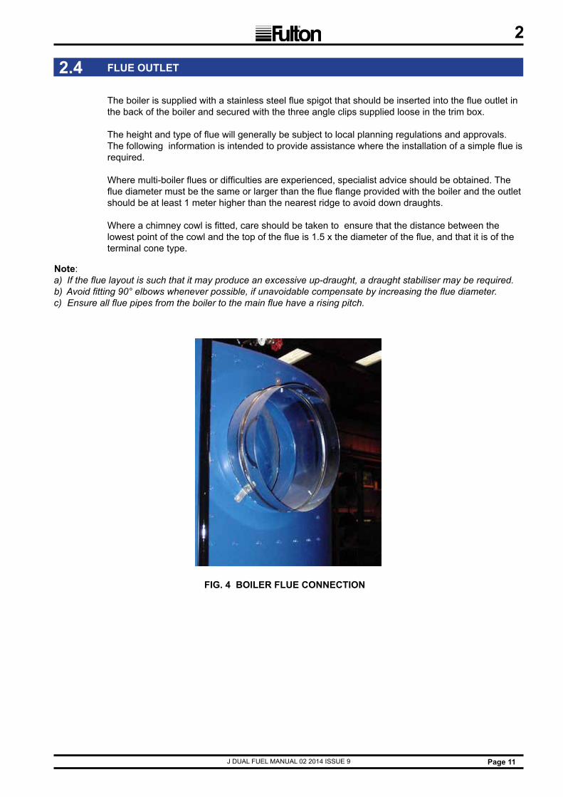
The boiler is supplied with a stainless steel flue spigot that should be inserted into the flue outlet in the back of the boiler and secured with the three angle clips supplied loose in the trim box. The height and type of flue will generally be subject to local planning regulations and approvals. The following information is intended to provide assistance where the installation of a simple flue is required.
Where multi-boiler flues or difficulties are experienced, specialist advice should be obtained. The flue diameter must be the same or larger than the flue flange provided with the boiler and the outlet should be at least 1 meter higher than the nearest ridge to avoid down draughts. Where a chimney cowl is fitted, care should be taken to ensure that the distance between the lowest point of the cowl and the top of the flue is 1.5 x the diameter of the flue, and that it is of the terminal cone type.
FIG. 4 BOILER FLUE CONNECTION
2.4 FLUE OUTLET
Note:a) If the flue layout is such that it may produce an excessive up-draught, a draught stabiliser may be required.b) Avoid fitting 90° elbows whenever possible, if unavoidable compensate by increasing the flue diameter.c) Ensure all flue pipes from the boiler to the main flue have a rising pitch.

J DUAL FUEL MANUAL 02 2014 ISSUE 9Page 12
2
Feedwater stop valve
Check valve
Feedwater Dip Pipe
Feedwater line
The quality of the water used in the boiler will affect the life and performance of the boiler. Feedwater contains solids and dissolved gases, these may promote encrustations of scale; foaming, priming, surging; corrosion and pitting; or caustic embrittlement. To prevent this happening it is strongly recommended that a reputable water treatment concern is consulted prior to commissioning the boiler.
Note: see Section 5.3 - Recommended Water Conditions.
Connect the feedwater pump discharge to the check valve inlet with 25mm. bore pipe (this may be reduced to 15 mm, where the discharge pipe work is shorter than 4m in total. The pump suction pipe work must remain at 25mm minimum diameter and be as short as possible). Install the stop valve supplied between the boiler and the check valve. The check valve must be positioned so that it is below the internal water level of the boiler, and should be installed at least 1m after the feedwater pump. The reason for this placement position is that the check valve is designed to have water on both sides to enable it to function correctly.
It is essential to protect the feedwater pump from damage by foreign matter, a strainer should therefore be fitted in the pump suction pipework.
Care should be taken to ensure the pipe work is properly aligned and not placing any strain upon the feedwater pump.
Note: The boiler feedwater pump may contain an inhibitor and this should be flushed from the pump prior to fit-ting the pump to the boiler. Failure to do so may result in water bounce or foaming due to the inhibitor forming a seal in the boiler. If the boiler is to be operated with little or no condensate return, consideration should be given to pre-heating the feedwater. If in doubt consult Fulton Ltd. The feedwater inlet connection on some boilers is located on the left hand side of the boiler below the sight glass assembly.
FIG. 5 BOILER FEEDWATER ARRANGEMENT
2.5 WATER SUPPLY

J DUAL FUEL MANUAL 02 2014 ISSUE 9 Page 13
2
FIG. 6A BOILER BLOWDOWN (models 6 - 15) FIG. 6 BOILER BLOWDOWN (models 20-60)
2.6 BLOWDOWN VALVE
There are four blowdown valves on the boiler, the boiler blowdown valve at the rear of the boiler, the water column blowdown valve and each of the water level gauge (sight glass) blowdown valves.
All of these valves must be connected to a blowdown receptacle of approved design. Regulations exist covering such items and care must be taken to ensure compliance with these regulations.
If in doubt regarding blowdown arrangements, consult Fulton Ltd.
Note: 20J - 60J main blowdown connection is integral, via a boiler mounted flange.Where possible the main blowdown pipework on 20 - 60J boilers should drop down to a union connection to allow removal of the inspection flange without the necessity to remove the blowdown pipework.

J DUAL FUEL MANUAL 02 2014 ISSUE 9Page 14
2
Ignition transformer
Flame detector Steam supplypipe
Burner assembly Oil supply connections
Safety valve
Water levelprobes
FIG. 7 BOILER TOP COMPONENTS
Electrical connection box
Oil supply valves
Adjustableair control
Oil pump Ignition electrodes
Secondary airdamper
Flame detectorlocation
Oil supply
Ignition electrodes

J DUAL FUEL MANUAL 02 2014 ISSUE 9 Page 15
2
WARNING Factory fitted safety valves are preset to protect the boiler only and must not be used to protect any
other items not capable of accepting boiler pressure.
An individual wiring diagram for the boiler is located on the inside cover of the control box. When referring to the electrical specification of the boiler, the reference number located on the rear inside wall of the control box and the wiring diagram number should be quoted. The audible alarms provided are mounted on the side of the control panel, if not audible they should be repositioned where they can be heard by a person competent to take the appropriate action should the alarm be activated. Unless otherwise specified, the alarms supplied will be mains voltage models. Unless otherwise specified all models are supplied with burner motors and feed water pump motors arranged for operation on a three phase supply. The power ratings and requirements are given in Section 5.2 - Boiler Specifications.
2.7 MAIN STEAM VALVE
2.8 STEAM SAFETY VALVES
The main steam stop valve should be inserted in the steam line approximately 305mm from the top of the boiler.
2.9 WATER GUAGE SET
(The design may vary from that illustrated) Numbers may vary due to individual country’s regulations.)Boilers are normally supplied with two complete water level gauge sets. The water level gauge blowdown cock should be connected to the auxiliary blowdown line from the water column blowdown valve in 3/8 in. soft copper tubing.
2.10 ELECTRICAL REQUIREMENTS
Safety valves are factory fitted and preset, they MUST NOT be adjusted. The discharge outlet should be piped to a safe discharge point and the piping so arranged that any condensate trapped in the pipework will drain away from the valve.
Note: It is recommended that the safety valve discharge pipework is installed to the requirements of BS806 clause 4.9.7. / BSEN 134801-1:2002
a) The lift pressure is indicated on the safety valve. (Do not adjust).b) The safety valve fitted to the boiler is designed to prevent the boiler exceeding its design pressure.c) Any system connected to the boiler not capable of accepting boiler pressure must be protected
by a separate safety valve set to the required pressure.
FIG. 8 CONTROL BOX
Fuel selector
Recommended water treatment
TDS blowdown controller
Note: It is advisable for dual fuel burners, that the offline fuel is manually isolated with a proof of closure microswitch that is interlocked with the online control circuit.e.g. gas supply proof of closure interlocked with the oil burner control circuit.oil supply proof of closure interlocked with the gas burner control circuit.
!

J DUAL FUEL MANUAL 02 2014 ISSUE 9Page 16
2
FIG. 9 GAS SUPPLY
2.11 GAS SUPPLY
Verify that the burner is suitable for the type of gas being supplied. Ensure that the piping from the meter is the correct size, and that a gas cock is inserted in the line between the boiler and the meter. To avoid pressure drops, eliminate all unnecessary bends and elbows in the pipework between the gas meter and the boiler. A scale trap is provided on the gas train and should be used.Burners suitable for operation on natural and manufactured gas are supplied with gas trains or a modular gas head. A minimum pressure of 18 mbar at the specified flow rate, is required at the gas train for natural gas installations and a minimum pressure of 50 mbar is required at the gas train for manufactured/L.P gas installations.If the gas supply is in excess of 100 mbar for natural gas a suitable regulator is required before the main gas valve.Burners arranged for operation on L.P. gas are supplied with gas trains. It is essential that the MAXIMUM pressure of the gas at the gas train does not exceed 80 mbar and does not fall below 50 mbar. A suitable regulator is required before the main gas valve.To obtain these pressures, a pressure regulating device or service governor must be fitted to the supply line from the storage tank to the boiler gas train.Careful consideration must be given to the siting of LPG storage tanks to prevent over pressure conditions arising, due to temperature rises caused by solar gain.
Main gas valve assemblyMain gas line isolating valve
Pilot line ball valve
Pilot line governor
Pilot line gas valves

J DUAL FUEL MANUAL 02 2014 ISSUE 9 Page 17
2
FIG. 10 OIL SUPPLY
Oil feed solenoid valves
Oil pump
Oil feed lines
Out In
2.12 OIL SUPPLY
The positioning of the oil storage tank will be dependent on site conditions and local regulations. The burner fuel pump is of the bypass type requiring the installation of feed and return lines between the oil storage tank and the boiler. These lines should be in tubing of a minimum bore of 10 mm. A fire valve, stop valve and check valves should be inserted in the oil feed line. To avoid blockages in the fuel pump and burner nozzle, a metal cartridge oil filter should be fitted. Fibrous cartridge filters are not recommended. The final connections between the fuel pump and the feed and return lines should be made with the flexible fuel lines supplied. If the oil storage tank is positioned higher than the boiler, a non-return valve should be fitted to the return line. To overcome suction problems at the fuel pump, all vertical lifts in the feed pipe should be made as close to the boiler as possible. The burner fuel pump pressure is preset at the factory and should not require adjustment.

J DUAL FUEL MANUAL 02 2014 ISSUE 9Page 18
2
Steam pressure gauge
Plug
Steam cock
Pressure controller connection point
Syphon
F03210
The steam pressure gauge assembly should be assembled in accordance with Fig. 11 using a suitable sealant on all joints. The gauge should be facing front towards the electrical control box and/or the operator of the boiler. Screw the assembly into the top of the boiler and connect the copper tube from the pressure controller located on the side of the control box to the nipple provided on the assembly.
FIG. 11 STEAM PRESSURE GAUGE
2.13 STEAM PRESSURE GAUGE

J DUAL FUEL MANUAL 02 2014 ISSUE 9 Page 19
2
2.14 COMMISSIONING THE BOILER
Dual fuel boilers that use a common burner assembly and have a switch change over from one fuel to another, have to be commissioned on the basis of a primary fuel (usually gas), with the secondary fuel as a back-up. The primary fuel should be commissioned as 2.16 oil firing or 2.17 gas firing.The secondary fuel then has to be commissioned using the air settings for the primary fuel. In practice this means adjusting the fuel input of the secondary fuel to achieve acceptable combustion.As more air is required for oil combustion the consequences are that when oil is the secondary fuel there will be a small reduction in the fuel input rate.
It is essential that the commissioning procedures listed below are carried out by a Fulton Service Engineer who will have the necessary experience and testing equipment to ensure that the installation is not only correct, but is operating safely and at optimum efficiency.
Flue CommissioningPrior to initial firing of the boiler, the flue must be checked for leaks.This is done by BOTH of the following methods:
a. Visual InspectionCheck joints between all flue sections for quality of seals. Where the flue passes through the structure of the building use your judgement as to the integrity of this section of the flue.
b. Smoke TestWith the flue capped, the drain stabiliser pipe (if fitted) blanked and a smoke generator inserted into the flue, there should be no smoke visible from the flue.If either of these tests fail or at any time during boiler operation, there is doubt about the integrity of the flue, shut down the boiler and contact Fulton Ltd immediately.
Note: Flues that are designed to operate with positive pressure should be tested to the latest regulations.

J DUAL FUEL MANUAL 02 2014 ISSUE 9Page 20
2
FIG. 12 BASIC BURNER ELECTRODE SETTINGS
Flame detector
Mains gas supply
Pilot gas supply
Ignition electrodes
FIG. 13 FEEDWATER STOP VALVE FIG. 14 IGNITION FLAME DETECTOR
Feedwater stop valve
NOTES:
1. GAS ELECTRODE TIP SHOULD BE POSITIONED 3mm FROM THE END OF THE GAS SUPPLY PIPE TO ENABLE IGNITION.
2. OIL ELECTRODE TIP SHOULD BE POSITIONED 3mm FROM ONE OF THE OIL NOZZLES.
Oil Ignition Electrodes
Gas Ignition Electrode
Burner Plate
205
258
271.5
89
141
196
dimensions in mm

J DUAL FUEL MANUAL 02 2014 ISSUE 9 Page 21
2
2.14.1 BOILER INSPECTION AND INITIAL FIRING OIL
1. Ensure the boiler has been washed out after installation. It is advisble to conduct a water analysis before operating the boiler. Examine the probes in the water column and the boiler shell. Replace any damaged probes.
2. Remove the burner and check that the electrodes have not been damaged. If the burner is fitted with a flame detector, remove the detector and check for damage.
3. Check that the burner is the correct type for use in a dual fuel boiler. Replace the burner and reconnect the copper oil lines to the oil nozzle assembly and gas connection, ensure these connections are tight. Reconnect the ignition leads and replace the flame detector.
4. Ensure that the gas supply isolation valve is closed.
5. Check the rotation of the oil pump motor. Ensure that the oil supply flow and return valves are open. Bleed the oil pump.
6. Ensure that all wiring connections are correct and that all terminal screws are tight.
7. A barometric type draught stabiliser, if fitted in the flue, should be set for a draught of - 0.01 in. to 0.02in. (0.025 mb to 0.05 mb) of water column pressure with the burner off.
8. Check that the visual flame signal display on the burner controller (5 LED bar) is fully illuminated during pilot and main flame.
9. Open all the valves in the feedwater line. Switch on the feedwater pump motor and fill the boiler, see Section 3 - Operation. The operation of the pump controls should be checked by using the boiler blowdown valve (located at the rear of the boiler). When the water level sight gauge is reading half full, the pump will stop. Open the boiler blowdown valve and slowly drain the boiler. When the water level falls below the PUMP ON probe, the pump should start. If the pump does not start, check the probe connections. Close the boiler blowdown valve.
10. Start the burner as detailed in Section 3 - Operation. Allow time for the fuel pump to prime itself.
11. After the burner has been firing for approximately five minutes, adjust the main air control gate to obtain a clean combustion.
Main air adjusting screw
Primary air adjustmentMain air adjustment plate
FIG. 15 MAIN AND PRIMARY AIR CONTROLS

J DUAL FUEL MANUAL 02 2014 ISSUE 9Page 22
2
11. Observe the flame through the peephole between the electrodes and adjust the primary air control so that the flame cannot be seen 'backing up' the blast tube.
12. Observe the flame through the eye glass in the burner plate. The desired flame shape is a full swirling flame brushing the wall of the furnace. Adjust the air controls to achieve this shape.
13. Check the operation of the low water safety controls as detailed in Section 3 - Operation.
14. Adjust the steam pressure control to suit the boiler application. It should be borne in mind that boilers are designed to operate most efficiently at their maximum operating pressure. When boilers are to be operated below a pressure of 80 psi (5.5 bar) consideration should be given to the fitting of a pressure reducing set. See Section 2.8 - Safety Valve setting.
FIG. 16 BURNER FLAME OBSERVATION GLASS
6mm Peep hole
Main flame observation glass
Primary air Adjustment

J DUAL FUEL MANUAL 02 2014 ISSUE 9 Page 23
2
The commissioning procedures listed below must be carried out by a Fulton service engineer who will have the necessary experience and testing equipment to ensure that the installation is not only correct, but is operating at maximum efficiency.
1. Ensure the boiler has been washed out after installation. Conduct a water analysis before operating the boiler. Examine the probes in the water column and the boiler shell. Replace any damaged probes.
2. Remove the burner and check that the electrodes have not been damaged. If the burner is fitted with an flame detector, remove the detector and check for damage.
3. Check that the burner is the correct type for use with the gas being supplied.
4. Ensure that the oil supply isolation valve is closed. Check that the gas supply valve is open. 5. Ensure that all wiring connections are correct and that all terminal screws are tight.
6. Check that the visual flame signal display on the burner controller (5 LED bar) is fully illuminated during pilot and main flame.
7. A barometric type draught stabiliser, if fitted in the flue, should be set for a draught of - 0.01 in. to 0.02 in. (0.025 mb to 0.05 mb) of water column pressure with the burner off.
8. Open all the valves in the feedwater line. Switch on the feedwater pump motor and fill the boiler, see Section 3 - Operation. The operation of the pump controls should be checked by using the boiler blowdown valve (located at the rear of the boiler). Open the boiler blowdown valve and slowly drain the boiler. When the water level falls below the PUMP ON probe, the pump should start. If the pump does not start check the probe connections. Close the boiler blowdown valve.
9. After purging the gas lines of air. Start the burner as detailed in Section 3 - Operation. Check the readings on the micro-ammeter for the pilot and main flames, adjusting the primary/secondary air control to obtain the maximum readings.
10. After the burner has been firing for approximately five minutes. adjust the main air control gate to obtain a clean combustion.
11. Observe the flame through the peephole between the electrodes and adjust the primary air control so that the flame cannot be seen ‘backing up’ the blast tube. Observe the flame through the eye glass in the burner plate. The desired flame shape is a full swirling flamebrushing the wall of the furnace. Adjust the air controls to achive this shape.
12. Check the operation of the low water safety controls as detailed in Section 3 - Operation.
13. Adjust the steam pressure control to suit the boiler application. It should be borne in mind that boilers are designed to operate most efficiently at their maximum operating pressure. When boilers are to be operated below a pressure of 80 psi (5.5 bar) consideration should be given to the fitting of a pressure reducing set. See Section 2.8 - Safety Valve setting.
2.14.2 BOILER INSPECTION AND INITIAL FIRING GAS

J DUAL FUEL MANUAL 02 2014 ISSUE 9Page 24
2
Setting the gas pressure switch. - Models 6 - 30
1. Remove the adjustable gas pressure switch cover.
2. Set the pressure switch by rotating the setting wheel to the desired pressure. Normally set to 2.5 mbar below the normal supply pressure with the boiler running.
Setting the pressure regulator. - Models 6 - 30
1. Remove the regulator cover.
2. Using a screwdriver, set the regulator to the desired pressure: Clockwise to increase pressure. Anticlockwise to decrease pressure. Gas pressure can be tested at the test point on top of the gas output flange.
Setting the main gas flow (V2) - Models 6 - 30. - factory set, would not normally be altered.
1. Loosen the security screw on the setting plate.
2. Turn the setting plate: Clockwise to reduce gas flow. Anticlockwise to increase gas flow.
Rapid stroke adjustment Model 6 - 30 - factory set, to slowest possible opening, would not normally be altered.
1. Unscrew the adjustment cap from the hydraulic brake.
2. Invert the cap and use as a tool: Clockwise = slowest opening time. Anticlockwise = fastest opening time.
2.15 GAS MONOBLOCS (NON MODULATING BURNERS)
FIG. 17 PRESSURE CONTROLLER
Note: In order to utilise the maximum flash steam capability of the boiler it is essential that the boiler is operated at the maximum working pressure (10.34 bar) and then pressure reduced down to the required system pressure.
If the pressure control is fitted with a differential scale: (see OEM literature in Section 5)
1. Set the main scale pressure to the maximum pressure required (system pressure). Do not exceed the boiler operating pressure.
2. Set the differential scale to it’s minimum pressure. If the pressure control has a fixed differential, i.e. no adjustable differential scale, set the main scale to the maximum pressure required.
When multiple boilers are fitted with asequence control:
1. Set the main scale and differential scale as
above.
2. Set the setback pressure control to the required set back pressure.

J DUAL FUEL MANUAL 02 2014 ISSUE 9 Page 25
2
Hydraulic Brake
Main gas flow adjustment
Test pointconnection
(see attached manufacturers leaflets).
FIG. 18 6J - 30J GAS VALVE: MAJOR COMPONENTS (NON-MODULATING BURNER)
Gas outputflange
Test point connectiondownstream of Valve 2
Test point connectionupstream of Valve 1
Gas inputfilter cover
Test pointconnection
downstreamof Valve 1
Adjustablepressure switch
Operating indicator
Output pressure controller adjusting screw
Output pressure controlleradjusting screw
Hydraulicbrake
Adjustable pressure switch
Operating indicator
Test pointconnection
downstream of Valve 1
Gas input filter cover
Test pointconnection
upstream ofValve 1
Gas input flange
Test pointconnection
downstream ofValve 2
Main gas flowadjustment
2.15.1 MULTIBLOC GAS VALVES 6J - 30J MODELS (NON MODULATING BURNER)

J DUAL FUEL MANUAL 02 2014 ISSUE 9Page 26
2
SETTING THE BURNER FOR LOW FIRE / HIGH FIRE, Models 40J, 50J AND 60J (Non Modulating Burner)
The correct settings for low fire/high fire operation are obtained by making adjustments to the two stage Multibloc valve and the high/low fire steam pressure control.
a) Set the gas input to the boiler for correct input on high fire. This should be done where possible by using the gas meter. Adjust the main air gate and primary/secondary air adjustment to obtain optimum combustion conditions.
b) Adjust the high/low fire steam control to cut out at approximately 5 psi below the setting of the main steam pressure control.
c) Adjust the two-stage multibloc valve by rotating the low fire adjustment ring to obtain a low fire gas input of approximately 80% of high fire. Leave the air gate adjustments as for high fire.
Hydraulic brake
Solenoid
Low fire adjustment ring
Test point connectiondownstream of valve 1
Test point connectionupstream of valve 1
Test point connectiondown stream of valve 2
Main gas flow adjustment

J DUAL FUEL MANUAL 02 2014 ISSUE 9 Page 27
2
GAS ACTUATOR
GAS GOVERNOR & VALVE
Servo motor body
Valve coupling
Gas governor
Filter caps
Filter & main housing
Gas out flange
Gas valve
Electrical connections
Low gas pressure switch
Gas in flange
2.15.2 MULTIBLOC GAS VALVES 30J - 60J MODELS (FULLY MODULATING BURNER)
FIG. 19 30J - 60J GAS VALVE: MAJOR COMPONENTS (FULLY MODULATING BURNER)

J DUAL FUEL MANUAL 02 2014 ISSUE 9Page 28
2
2.17 CLEANING STEAM LINES AND PRESSURE VESSELS
During the first week of boiler operation, clean all oil and dirt from the boiler, the steam line and condensate return line.
1. Disconnect the condensate return pipe adjacent to the condensate return tank.
2. Direct the returns to a floor drain or other safe discharge point and make safe.
3. Leave in this position for one week to allow all impurities to flush through.
4. Drain the boiler completely each day.
5. After the week is completed, drain and flush the condensate return tank, removing all installation sediment. Reconnect the condensate return pipe to the condensate return tank.
WARNINGDo not change the boiler fuel withoutconsulting the boiler manufacturer.
The correct setting for fully modulating operation are made by adjusting the parameters via the Siemens LMV burner controller.
All adjustments need to be carried out by a suitably trained service engineer.
All parameter adjustments are password protected.
2.16 SETTING THE BURNER CONTROLS FOR FULLY MODULATING MODELS 30 - 60
!

J DUAL FUEL MANUAL 02 2014 ISSUE 9 Page 29

J DUAL FUEL MANUAL 02 2014 ISSUE 9Page 30
FIG. 20 BOILER OPERATION
Monobloc gas valve
Safety valve
Steam pressure gauge
Water level limiters
steam outlet
Feedwater inlet
Gas supply inlet
Oil valves
Oil pump
Water level gauges
Door electrical isolator
Operator control panel
Operating steampressure controller
High/Low steam pressure controller
Note: Control Boxes vary with specification
High pressure steam controller
TDS controller
Pump interrupt /pump run switch
Motorised high /low control
Watercolumn

J DUAL FUEL MANUAL 02 2014 ISSUE 9 Page 31
3
SECTION 3 - OPERATION
The following instructions are given for the guidance of the operator in the use of the J Series Dual Fuel boiler and to provide adequate information to ensure that when the boiler is put into use it will be done safely and without risk to health. Where original equipment Service Manuals are supplied, they must be read and understood in conjunction with this manual. All warnings and cautions must be observed.
DRYING OUT TIME
The refractory casing of the boiler is made from a material that uses a high proportion of water in the mixing process. Whilst some of the water is driven off by chemical reaction and the initial test firing, the refractory is still ‘wet’ when the boiler is delivered. For a few days after the boiler is commissioned and in service, water will be seen running from the bottom of the casing and from around some branch pipes.This is perfectly normal and part of the drying process.
3.1 GENERAL
3.2 BOILER CONTROLS
The following brief description of the controls used on the J Series Dual Fuel boiler is intended to provide the operator with a basic understanding of the operating principles, which is essential for the continued efficient operation of the boiler.
Note: All the controls are of the ‘fail-safe’ type and are wired in series; failure of any one will automatically shut down the boiler.
Low Water Relays and Feed Water Pump Relays. These relays operate in conjunction with probes suspended in the boiler and water column to automatically maintain the level of water in the boiler and to cut off the burner should the water level fall to an unsafe level.
Steam Pressure Control(s). Located on the control panel box and connected to the steam pressure gauge assembly by copper tube, the pressure regulator controls the On/Off cycle of the burner, shutting the burner off when maximum pressure is reached and switching it on when the steam pressure falls.
Note: A set-back pressure controller is fitted when multi-boilers are fitted with a sequence control.
Burner Programmer. This is the main control in the panel box. The programmer in conjunction with a sensing device ‘supervises’ the ignition sequence, proves the flame is satisfactory and finally ‘monitors’ the established flame. Should any fault occur, either during the ignition sequence or during normal running, the programmer will immediately go to ‘lockout’ and the Multibloc gas valve will be closed.
Air Pressure Switch. Mounted on the burner scroll, this switch is operated by the pressure of air entering the burner through the throat of the scroll. Lack of air, or insufficient pressure, will prevent the switch completing the circuit thus preventing the burner from operating.
Fuel Pump. Mounted on the burner scroll and driven by the burner motor, the fuel pump delivers oil to the burner nozzels at the correct pressure to allow complete atomisation and therefore combustion.
CONTINUED...

J DUAL FUEL MANUAL 02 2014 ISSUE 9Page 32
3
3.2 BOILER CONTROLS - CONTINUED
Note: Boilers fitted on skid units and in plant rooms are interlocked with the feedwater and condensate return tank, after switching the boiler on at the boiler control box isolator switch, the reset button on the tank control box must be reset. This reset must also be selected after any electrical outage.
Gas Head Assembly Consists of a multiblock located in the main gas line, incorporating an integral governor, pressure switch and gas valves. The independent pilot line having a manual gas cock, a governor and two electrically powered gas valves. The pilot governor maintain a constant pressure of gas during the ignition sequence. The electrically powered gas valves are controlled by the burner programmer.
PUMP CONTROLPump Interrupt/Pump Run Switch.
Fitted on the left side of the control panel, used to override (switch off) the pump controls during evaporation tests.
FIG. 21 ALARM AND INDICATOR LIGHTS
FIRING
HIGH
LOW WATERBOILER
FIRING
FLAME
START
FLAME
MAIN
START
SECOND
POWER
ON
PUMP
OFF OIL
PUMP &
OFF
BURNER
ONIGNITIONPRESSURE
LOW GAS LOW
WATER
1st LOW
GASRESET
MAINPILOT
HIGH STEAM
PRESSURE
FAILURE
RESET
FLAME
FLAME FLAME
FLAME FLAME
& RESET

J DUAL FUEL MANUAL 02 2014 ISSUE 9 Page 33
3
Indicator lights are fitted to the control panel as an additional aid to the operator. The meaning and operating sequence of these lights is as follows:
Start / Low Water Reset This switch is used to start the boiler and to reset the low water alarm. When the switch is pressed to initiate the start-up sequence, the low water alarm lamp also illuminates and the low water audible alarm sounds. Keeping the switch depressed for approximately 2 seconds cancels the low water alarm and initiates the burner start sequence. Illumination of this switch and sounding of the audible alarm at any other time other than at switch on indicates that the boiler has gone to a lockout (safe condition) due to low water. Once the water in the boiler has been restored to a safe operating level, pressing the switch will reset the controls.
Circuit On Indicates that power is being supplied to the control panel.
Low Water Alarm (1st. low water).This light will energise, when the boiler is switched on and the water level is between 1st. low water and 2nd. low water. A light will illuminate and a pulsing alarm sound. Low Water Reset (2nd low water). The 1st. low water light and alarm are replaced by the 2nd. low water light and a continuous alarm, indicated by the low water reset switch. The second alarm must be reset, the first alarm will be automatically reset by the return to normal water level.
Ignition This lamp indicates the ignition transformer has been energised, it will remain illuminated for 5 - 10 seconds approximately during the ignition sequence.
Burner On This lamp indicates that the burner is running and that the flame is being monitored by the burner programmer.
Flame Failure Alarm (reset) This switch will illuminate if the burner goes to a lockout condition due to flame failure. Pressing the switch will reset the burner controller.
Oil Valve The two lamps provide a visual indication that the magnetic oil valves have been energised. Low Flame / Start and Main FlameModels 40J and 60J are fitted with the following indicator lamps in place of the two oil valve indicator lamps: The burners on models 40J and 60J are fitted with a two-stage combustion system. The low flame start lamp indicates that the first stage of combustion is in progress and that the burner should be firing. Once the second stage of combustion is reached (full firing position), the low flame start lamp extinguishes and the main flame lamp illuminates.
This lamp will remain illuminated until the burner is shut down.
3.3 INDICATOR LIGHTS
! WARNINGNo more than two attempts should be made to start the boiler by resetting the
flame failure alarm (reset) Further attempts could cause the boiler and fluesystem to fill with vaporised oil which could cause an explosion.

J DUAL FUEL MANUAL 02 2014 ISSUE 9Page 34
3
Carry out the following procedure on the initial start up of the boiler and on every subsequent occasion when restarting the boiler after a shut down:
1. Ensure that the main steam stop valve is OPEN.
2. Ensure that the steam pressure gauge isolating valve is OPEN.
3. Select the fuel to be used, ensure that the valves in the selected fuel line(s) are open, and the alternative fuel lines are closed (see Section 3.4).
4. Ensure that all the valves in the feedwater line are OPEN.
5. Ensure that the main blowdown valve is CLOSED.
6. Ensure that the water level gauge isolating valve(s) is OPEN.
7. Ensure that the water level gauge blowdown valve(s) is CLOSED.
8. Ensure that the column blowdown valve is CLOSED.
9. Ensure that the boiler and pump switch is in the OFF position.
10. Ensure that all appropriate electrical isolators are switched ON.
11. Ensure the pump interrupt switch is switched OFF (PUMP RUN).
12. Press the boiler/pump switch to the PUMP ONLY position.
Note: If the boiler water level is below its correct level, the water pump will operate. When the water reaches the correct level (two thirds up the water level gauge sight glass), the pump will stop. If the water level is above the top of the water level gauge sight glass, drain off until the level is in the middle of the water level gauge sight glass.
3.5 FILLING THE BOILER - ALL MODELS
! CAUTION The feed pump seals are water cooled.
The pump must never be allowed to run whilst dry, irreparable damage may result. Ensure the pump is fully primed before energising the motor.
1. Switch OFF the electrical supply at the door isolator switch.
2. Isolate the supply lines of the fuel not required.
3. Open the isolation valve on the required fuel supply.
4. Switch the fuel selector switch to the required fuel. 5. Switch ON the electrical supply to the boiler at
the door isolator. 6. Start the burner.
3.4 CHANGING TO THE ALTERNATIVE FUEL
TDS Blowdowncontrol
Fuel selectorswitch
FIG. 22 BOILER MAINTENANCE

J DUAL FUEL MANUAL 02 2014 ISSUE 9 Page 35
3
1. OPEN all the valves in the oil supply line.
CAUTIONFailure to open the oil supply line will damage the oil pump.
A pump damaged under these circumstances will not be replaced by warranty.
2. CLOSE the steam stop valve.CLOSE the gas supply isolation valve fitted with the proof of closure microswitch.
3. Select the control switch to PUMP AND BOILER position, the low water alarm bells will sound, the LOW WATER RESET switch will illuminate.
4. Press the LOW WATER RESET switch for two seconds maximum.The alarms will stop, and the alarm lights extinguish.
5. The burner start sequence will commence.
6. After a maximum of one minute the burner should be firing, and the BURNER ON lamp should illuminate.
3.6 STARTING THE BOILER - ALL MODELS GAS
WARNINGThe system should be raised to temperature slowly to allow
for expansion and to avoid thermal shock and water hammer.
This can be achieved by one of two methods:
a) Crack open the main steam valve and allow the system to heat up slowly, (minimum 15 minutes) before fully opening the main steam valve.
b) Open the main steam valve when starting the boiler, allowing the boiler and system to heat up together.
Note: This can lead to water logging of the steam lines until full pressure is achieved.If fitted, TDS Panel Mounted Controllers (BC3250) must be reset after any break in electrical supply to the unit.
1. OPEN all the valves in the gas mains supply to the boiler.
2. OPEN the manual gas cocks on the Pilot and Main lines of the gas head.CLOSE the steam stop valve.CLOSE the oil supply isolation valve with the proof of closure microswitch.
3. Select the control switch to PUMP AND BOILER position, the low water alarm bells will sound, the low water reset will illuminate.
4. Select the low water reset switch for two seconds maximum.The alarms will stop, and the alarm lights extinguish.The burner start sequence will commence.
5. After a maximum of two minutes the burner should be firing, and the main gas light be ON.
6. When the boiler has achieved the required (set) pressure, the main steam isolating valve should be slowly opened allowing steam to enter the system distribution pipework.
3.7 STARTING THE BOILER - ALL MODELS OIL
!
!

J DUAL FUEL MANUAL 02 2014 ISSUE 9Page 36
36. When the boiler has achieved the required (set) pressure, the main steam isolating valve should
be slowly opened allowing steam to enter the system distribution pipework.
WARNINGThe system should be raised to temperature slowly to allow
for expansion and to avoid thermal shock and water hammer.
This can be achieved by one of two methods:
a) Crack open the main steam valve and allow the system to heat up slowly (minimum 15 minutes), before fully opening the main steam valve.
b) Open the main steam valve when starting the boiler, allowing the boiler and system to heat up together.
Note: This can lead to water logging of the steam lines until full pressure is achieved.If fitted, TDS Panel Mounted Controllers (BC3250) must be reset after any break in electrical supply to the unit.
!

J DUAL FUEL MANUAL 02 2014 ISSUE 9 Page 37
4
SECTION 4 - MAINTENANCE
Inspect the steam and feedwater pipework, valves and fittings for signs of leakage. If leaks are suspected, shut the system down and evacuate the system to atmospheric pressure before attempting any repairs.
Note: Ensure that the water level is maintained during the pressure build up. If any part of the equipment is not operating correctly, the fault should be investigated before the boiler is used. Ensure that all blowdown pipework is safe and discharged to a blowdown receptacle.
Fulton Ltd recommends that these tests and checks are carried out on a regular basis to ensure that the boiler is operating safely.
Tests should be carried out by a competent person trained to perform such tests. If any test shows that the equipment is not operating correctly, the fault should be investigated and corrected before the boiler is used.
Any rectification or repairs should be carried out by trained, competent service personnel.
4.1 VISUAL CHECKS
4.2 WATER LEVEL AND LOW WATER SAFETY CONTROLS
The following procedures ensure the correct functioning of the water level controls and the low water safety controls.
a) If the boiler is not firing and not under steam pressure, lower the water level using the main blowdown valve:
If the pump is running:
1. Observe the water level in the water level gauge (sight glass).
2. Verify that the pump continues to run until the Pump Off level is reached and then switches off.
If the pump is not running:
1. Check that the water level in the water level gauge is between Pump On and Pump Off levels.
2. Lower the water level by opening the main boiler blowdown valve.
3. Verify that the pump starts to run when the water level reaches the Pump On level.
4. Close the main boiler blowdown valve.
5. Continue to observe the water level in the water level gauge and verify that the pump continues to run until the Pump Off level is reached and then switches off.
4.2.1 PUMP TEST

J DUAL FUEL MANUAL 02 2014 ISSUE 9Page 38
4b) If the boiler is firing and under load, lower the water level by evaporation, observing a
pump cycle:
If the pump is running:
1. Observe the water level in the water level gauge.
2. Verify that the pump continues to run until the Pump Off level is reached and then switches off.
If the pump is not running:
1. Check that the water level in the water level gauge is between Pump On and Pump Off levels.
2. The water level will lower through natural evaporation.
3. Verify that the pump starts to run when the water level reaches the Pump On level.
4. Continue to observe the water level in the water level gauge and verify that the pump continues to run until the Pump Off level is reached and then switches off.
4.2.2 1ST LOW WATER LEVEL CHECK
1. Ensure that the boiler is firing, the feedwater pump is not running and that the water level is between Pump On and Pump Off.
2. Switch off the pump using the Pump Interrupt/Pump Run switch.
3. Allow the water level to lower by natural evaporation below the 1st Low Water level.
4. Verify that the Low Water lamp illuminates, the Low Water audible alarm sounds and that the burner stops firing. Do not allow the water level to drop below the bottom of the water level gauge (sight glass).
If the test fails, turn the boiler off and ensure that the fault is rectified before the boiler is used.
5. Switch on the pump using the Pump Interrupt/Pump Run switch.
6. Verify that the pump runs and refills the boiler. When the water level rises above the 1st Low Water level, verify that the Low Water lamp extinguishes, the Low Water audible alarm silences and the burner fire sequence starts.
7. Verify that the pump continues to run until the Pump Off level is reached and then switches off.

J DUAL FUEL MANUAL 02 2014 ISSUE 9 Page 39
4
FIG. 23 PUMP INTERRUPT SWITCH
4.2.3 2ND LOW WATER LEVEL CHECK
1. Ensure that the boiler is firing, the feedwater pump is not running and that the water level is between Pump On and Pump Off.
2. Switch off the pump using the Pump Interrupt/Pump Run switch.
3. Allow the water level to lower by natural evaporation to the 1st Low Water level.
4. Verify that the Low Water lamp illuminates, the Low Water audible alarm sounds and that the burner stops firing. Do not allow the water level to drop below the bottom of the water level gauge (sight glass).
If the test fails, turn the boiler off and ensure that the fault is rectified before the boiler is used.
5. Allow the water level to lower further by natural evaporation below the 2nd Low Water level. Do not allow the water level to drop below the bottom of the water level gauge.
6. Verify that the Low Water Reset switch illuminates.
If the test fails, turn the boiler off and ensure that the fault is rectified before the boiler is used.
7. Switch on the pump using the Pump Interrupt/Pump Run switch.
8. Verify that the pump runs and refills the boiler. When the water level rises above the 1st Low Water level, verify that the 1st Low Water lamp extinguishes but the burner fire sequence does not start.
9. Press the Low Water Reset switch- Verify that the 2nd Low Water lamp and audible alarm extinguishes and the burner starts.
10. Verify that the pump continues to run until the Pump Off level is reached and then switches off.

J DUAL FUEL MANUAL 02 2014 ISSUE 9Page 40
4
Keep the boiler, water level gauge (sight glass), water column and interconnecting pipework free from sludge and scale build-up by blowing down in the following manner:
Note: Where a boiler is operating continuously at steam pressure, advice should be sought from Fulton Ltd Service Department regarding the appropriate blowdown procedure.
FIG. 24 MAIN BOILER BLOWDOWN VALVE
Water column blowdown valve
FIG. 25 WATER COLUMN BLOWDOWN VALVE
4.3 MAIN BLOWDOWN
1. Start the boiler and generate not more than 10 psi of steam (see note).
2. Shut off both the burner and the pump.
Boiler Blowdown
1. Fully OPEN the boiler main blowdown valve for not more than 5 seconds, or as recommended by the water treatment specialist.
2. CLOSE the valve.
Note: Where high levels of suspended solids are produced, longer and/or more frequent blowdown may be required.
Note: The water column contains the pump On/Off probe, which is not safety interlocked.
1. Switch the pump off (pump interrupt) at the Pump Interrupt/Pump Run switch.
2. Open the water column blowdown valve for 5 seconds.
3. Close the water column blowdown valve and wait for 10 seconds for the boiler to refill and the water to stabilise in the vessel.
4. Switch the Pump Interrupt switch to Pump Run.
4.4 WATER COLUMN BLOWDOWN

J DUAL FUEL MANUAL 02 2014 ISSUE 9 Page 41
4
Blowdown the water gauge, set 1. 1. Open the gauge glass blowdown valve A 2. Close (for approx. 3 seconds) the top gauge valve B 3. Open valve B 4. Close (for approx. 3 seconds) the bottom gauge valve C5. Open valve C 6. Close valve A
Repeat for gauge set 2
On completion of the blowdown procedure ensure that all isolation valves are OPEN and all blowdown valves are CLOSED.
B
C
A
B
C
A
B C
A
WORKING POSITION
STEAM BLOWDOWN
WATER BLOWDOWN
With the boiler running under normal load conditions, and the pump stopped having just completed a refill cycle:
a) Ensure that the boiler water level is correct. b) Switch the pump OFF at the pump interrupt / pump run switch.
The water level in the boiler will lower through natural evaporation. When the level nears the bottom of the water level gauge sight glass, the first low water alarm will sound, the low water alarm lamp will illuminate and the burner will shut down. If it is required to check the second low water alarm, wait a further period for the LOW WATER RESET switch to illuminate.
When the check is complete, proceed as follows: c) Switch the pump ON at the pump interrupt / pump run switch. d) Press the low water reset switch. The pump will start to refill the boiler.
If the pump starts to run at any time during the test then the test must be abandoned and restarted from the beginning.
4.5 WATER GAUGE BLOWDOWN
4.6 EVAPOURATION CHECKS
Note: Where a Boiler is operating continuously at steam pressure, advice should be taken from a Fulton agent as to the appropriate blowdown procedure.
FIG. 27 Water Level Gauges(Sight Glasses)
FIG. 26 Water Level Gauge Operating Positions.

J DUAL FUEL MANUAL 02 2014 ISSUE 9Page 42
4
Boilers with manual blowdown valves
1. Ensure the boiler is cold. 2. Isolate the boiler electrics at the isolator on the control box door. 3. Isolate the feedwater tank and the feedwater pump. 4. Open the main steam valve and the boiler drain valve. 5. Open the drain valve on the blowdown vessel. 6. Open all valves in the drain lines.
Boilers with automatic blowdown systems
1. The boiler should not be under pressure. 2. The boiler should be cold. 3. Close the blowdown isolation valve. 4. Using a screwdriver located as shown ‘A’ in FIG. 29, push up and make a quarter turn, this will
lock the button in position and open the blowdown valve. 5. Using the blowdown isolation valve to throttle the flow, drain the boiler.
4.8 DRAINING THE BOILER
CAUTION Your local regulations could state boiler water above 43OC must not be discharged into the drain.
ALWAYS check your local regulations.
Note: Skid units and plant rooms have internal drainage systems which require the same procedures.
4.7 FLAME SENSOR TEST
FIG. 28 FLAME SENSOR REMOVAL
This test checks the operation of the flame safeguard sensor.
1. Ensure that the burner is firing.
2. Remove the flame sensor from its tube on the top of the burner.
3. Cover the sensor glass.
4. Verify that the burner goes out (the fan will run on for a short time but the flame should go out).
If the test fails, turn the boiler off and ensure that the fault is rectified before the boiler is used.
5. Return the flame sensor to its tube on the top of the boiler.
6. Fire the burner to ensure correct operation.
!

J DUAL FUEL MANUAL 02 2014 ISSUE 9 Page 43
4
To store the boiler in a corrosion-free situation there are three practical solutions:
1. Fully flood the boiler to exclude as much air as possible.
2. Drain the boiler completely. Remove all hand hole and manhole doors. Open all gas/oil side access doors.
3. As (2) but also introduce a form of convection heating to the gas/oil and water side. A very effective solution is to install a string of outdoor type waterproof light bulbs distributed throughout the boiler.
A
FIG. 29 AUTOMATIC BLOWDOWN VALVE
4.9 LONG TERM SHUT DOWN
4.10 INTERNAL INSPECTION
The lower hand hole doors should be removed after one month of operation and the interior of the boiler thoroughly examined. If scale or sludge build up is observed, it should be removed and the water treatment supplier advised.
New gaskets must be fitted every time a hand hole door is removed. Subsequent interior examinations should be carried out on a regular basis until satisfactory conditions are observed. Thereafter, inspections should be carried out at three monthly intervals.
FIG. 30 HAND HOLE
Hand Hole Cover Plate
Gasket
Crab

J DUAL FUEL MANUAL 02 2014 ISSUE 9Page 44
4
4.11 SCHEDULE OF OPERATOR TESTS AND CHECKS
WARNING Ensure any residual pressure within the boiler is completely vented
before working on the pressure vessel
CAUTIONIt is essential that regular checks are made to ensure that scale buildup is not taking place within the boiler. Such checks will ensure that water
treatment being applied to the boiler feedwater is effective.
The following procedures are designed to prevent the buildup of scale, silt or sludge in the bottom of the boiler, water level gauge (sight glass) and water column pipework, personnel involved in doing this work must have received the appropriate training in all aspects of maintenance and safety procedures.
In addition to these procedures, the advice of a water treatment specialist should be sought and followed.
The following schedule is the advice of Fulton Ltd. The frequency of tests and checks may vary according to site risk assessment and/or specific requirements of the country/territory that the boiler is installed in. Failure to maintain the boiler adequately may void the Fulton warranty.
Maintenance on gas related parts of a boiler must be carried out by competent, trained personnel who are GAS SAFE/ACS registered, and who have the necessary equipment to check combustion. If any fault is found during these operations, contact your Fulton representative.
WARNINGPrior to the commencement of any work requiring the removal of cover plates and the opening of
control panel box, the electrical supply to the boiler must be isolated.
4.11.1 DAILY
1. Visually inspect the steam and feedwater pipework, valves and fittings for signs of leakage. If leaks are suspected, shut the system down and evacuate the system to atmospheric pressure before attempting to repair the leaks.
2. Blowdown the Boiler (Refer to Section 4.3).
Note: If the boiler is being operated automatically on a time clock, the blowdown may be done once during the working day and once at the end of the day when generating 10 psig or less, providing this is sufficient to control the TDS level within limits.
3. Blowdown the Water Column (Refer to Section 4.4).
4. Blowdown the Water Level Gauge (sight glass), (Refer to Section 4.5).
4.11.2 WEEKLY (IN ADDITION)
WARNINGEnsure the fittings around the steam safety valve(s) are secure.
The safety valve will be very hot, do not operate the safety valve without protection.
!
!
!

J DUAL FUEL MANUAL 02 2014 ISSUE 9 Page 45
41. Ensure that the pipe from the safety valve outlet is not damaged and that it continues to a safe
blowdown point.
2. Pump Test (Refer to Section 4.2.1).
3. First Low Water Check (Refer to Section 4.2.2).
4. Second Low Water Check (Refer to Section 4.2.3).
5. Flame Sensor Test (Refer to Section 4.7).
6. Visually inspect the internal water space (Refer to Section 4.6).
7. Visually inspect the hand holes in the boiler. If any leakage is evident, the gasket needs replacing.
8. Visually inspect the flanged joint covering the rear inspection port in which the blowdown valve is fitted, if any leakage is evident, the gasket needs replacing.
9. Clean the water level gauges (sight glasses). If any leakage is evident, the gasket needs replacing.
10. Clean any water traps and strainers fitted in the feedwater line. Check feedwater and boiler water quality against the values given in Section 5.3 - Recommended Water Conditions.
11. Oil Burner: Remove, clean and adjust the oil nozzle and electrode assembly.
Note: Use only genuine Fulton replacement parts.
4.11.3 MONTHLY (IN ADDITION)
WARNINGEnsure the main electrical supply is isolated before starting work.
4.11.4 THREE MONTHLY (IN ADDITION)
12. Drain and isolate the boiler.
13. Remove the lower hand hole assemblies and inspect the interior of the pressure vessel for scale and sludge build up.
14. Remove the feedwater pipe from the top of the boiler. Ensure the pipe is not blocked, clean as required.
15. Gas Burner: Isolate the gas supply. Disconnect the gas head from the burner by unscrewing the union. Remove the burner plate screws, withdraw the burner assembly. Clean the ignition electrodes and reset FIG. 31 FEEDWATER PIPE REMOVAL

J DUAL FUEL MANUAL 02 2014 ISSUE 9Page 46
4
Burner plate screws Ignition leads
Burner scroll
Burner motor Photocell
Air gate Electrodes
Fan Oil feed pipe
Air damper Burner plate
Burner top plate
Oil line Rubber spider
Oil nozzle
Coupling Electrode holder
Air DeflectorFuel pump
Ignition transformer
FIG. 32 BURNER ASSEMBLY
FIG. 33 FLUE CLEANING
Cleaningthe FluesRemove cover
plates and gasket
Remove the clean-out doorto the flue passes and tothe bottom of the boiler.
Oil boiler illustrated.

J DUAL FUEL MANUAL 02 2014 ISSUE 9 Page 47
4
4.11.5 SIX MONTHLY (IN ADDITION)
It should be noted that after a Fulton boiler has been in operation for several months, pieces of burned metal will be found in the space at the bottom of the boiler. These pieces of metal are the remains of a light gauge metal form which was used during manufacture for the forming of the boiler insulation. This is normal and does not affect the efficiency or the life of the boiler in any way.
16. Remove the cover plates and clean-out door. Clean out the flue passes, check the refractories for soot or breakage, inspect the stainless steel ring. When replacing the cover plates and clean-out door, use new gasket material and furnace cement to ensure a tight seal, thus preventing the escape of hot gases.
17. Apply a small quantity of oil to the bearings of the burner motor and the feedwater pump motor.
18. Drain and flush the feedwater tank. Clean any filters in the tank, in the feedwater line or in the feedwater pump.
19. Remove and clean the water level probes, take care not to crack the porcelain. After replacement of the probes, check the operation of the low water cutoff relay and of the feedwater pump.
20. Remove the air gate and clean the fan.
21. Test the flue using the following procedure:
Visual InspectionCheck joints between all flue sections for quality of seals. Where the flue passes through the structure of the building use your judgement as to the integrity of this section of the flue.
Smoke TestWith the flue capped and a smoke generator inserted into the flue, there should be no smoke visible.
If either of these tests fail, shut down the boiler and contact Fulton Ltd immediately.
22. Remove components from all threaded stub pipes, clean and inspect, replace if required.
23. Remove the water level gauge (sight glass) and water column. Rod through the top connections of both to ensure that the holes in the baffle plates (approx. 6 mm dia.) inside the boiler are not obstructed.
24. Check the burner combustion to ensure that excess air and carbon monoxide values are within normal limits (see combustion values in Section 5).
25. Check the condition of the gas valve filter (if fitted), renew as required.
4.11.6 ANNUALLY (IN ADDITION)
26. Fulton Ltd recommend replacement of all threaded stub pipes on the boiler OR to your inspectors satisfaction.

J DUAL FUEL MANUAL 02 2014 ISSUE 9Page 48
4
Problem Cause RemedyIgnition Failure 1. Power Supply Check fuse or circuit breaker.
Reset or Replace as required.2. Ignition Electrodes Check for cracks in porcelain,if found replace the
electrode. Check electrodes for carbon build-up.Clean as required. Check settings, adjust if required.
3. Transformer Check voltage between transformer leads at terminal block to be sure transformer is live.
4. Burner Control Check voltage between ignition terminal and neutral, this check must be made before the control locks out. If no power, replace the control.
5. Air Settings Check main air adjustment and secondary air adjustment.
6. Faulty Air Switch Check for faulty air switch.7. Gas Valve Check filters in the valve block. Clean as
required.8. Gas supply Check for gas pressure and intermittent supply
problems.9. Loose wire connections Check connections to all components.
Flame Failure During Start-up
1. Power Supply Check fuse or circuit breaker.Reset or replace as required.
2. Gas supply Check for gas pressure and intermittent supply problems.
3. Air Settings Check main air adjustment and secondary air adjustment.
4. Ignition Electrodes Check electrodes for carbon build-up.Clean as required. Check for proper adjustment, readjust if necessary. Check for cracks in porcelain, if found replace the electrode.
5. UV Detector Check the detector is located correctly and clean.6. Burner Control Check voltage between ignition terminal and
neutral, this check must be made before the control locks out.If no power, replace the control.
7. Loose wire at fuel valve circuit.
Tighten wiring connections.
8. Contact open on Air Switch Adjust to the correct setting.9. UV Detector wiring reversed at control box.
Change to the correct terminals.
Flame Failure During Normal Run
1. Power Supply Check fuse or circuit, reset or replace as necessary.2. Gas Supply Check gas pressure coming into the gas train, if
low contact the gas supplier. Check the setting on the gas valve regulator, adjust as required.
3. UV Detector Check the detector is located correctly and clean.4. Faulty Air Switch Check for faulty air switch.5. Bad Combustion Check combustion readings.
4.12.1 TROUBLESHOOTING GAS BOILER

J DUAL FUEL MANUAL 02 2014 ISSUE 9 Page 49
4
Problem Cause RemedyBurner Cut-off 1. Gas Valve Check filters in the valve block.
Clean as required.2. Weak Pilot Adjust to larger pilot by adjusting pilot gas pressure
regulator.3. Faulty Level Control Test level controls, adjust or replace as required.4. Dirty or defective UV detector Clean or replace.
Poor Combustion 1. Refractory Bricks Check refractories to see if they are blocked with soot or broken in pieces. Clean or replace as necessary.
2. Stainless Steel Ring Check the ring is present (40J - 60J models) and fits tightly against the furnace wall.
3. Main Air Adjustment Check air adjustment. Air/fuel mixture may be off.Open main air gate until the flame brushes the furnace wall.
4. Secondary Air Adjustment Check main air adjustment, reset as required and secure in place. Check CO2 and O2 levels.
5. Draft Check draft with a gauge. Readings will vary between installations, if in doubt consult Fulton for a draft value for your system.
6. Dirty Flue Check flue for carbon build-up or blockage.Clean the flue.
7. Negative Room Pressure Ensure there are no exhaust fans running in the boiler room.
8. Dirty Fan Check fan for obstructions, clean as required.Burner Back Fires 1. Refractory Bricks Check refractories to see if they are plugged with
soot (Delayed Ignition) or broken in pieces.Clean or replace as necessary.
2. Ignition Electrodes Check electrodes for carbon build-up.Clean as required. Check for proper adjustment, readjust if necessary. Check for cracks in porcelain, if found replace the electrode.
3. UV Detector Check the detector is located correctly and clean.4. Draft Check draft with a gauge. Draft should be -.05 to
-.10 mbar with the burner off, or -.10 to -.15 mbar when operating.A barometric damper may need to be installed.
5. Negative Room Pressure Ensure there are no exhaust fans running in theboiler room.
6. Air Adjustment Check Air Adjustment settings.7. Gas Supply Check gas pressure coming into the gas train, if
low contact the gas supplier.Check the setting on the gas valve regulator, adjust as required.
4.12.1 TROUBLESHOOTING, CONTINUED. GAS BOILER

J DUAL FUEL MANUAL 02 2014 ISSUE 9Page 50
4
Problem Cause RemedyBoiler will not maintain pressure
1. Gas Supply Check gas pressure coming into the gas train, if low contact the gas supplier.Check the setting on the gas valve regulator, adjust as required. If possible meter the flow rate.
2. Dirty Flue Check flue for carbon build-up or blockage.Clean the flue.
3. Pressure Control Disconnect all power to the controller.Disconnect the wires from the controller.Place an OHM meter between the switch terminals. Lower the set point of the controller, the switch should make. Raise the set point and recheck, the switch should break. If the controller operates improperly, replace it.
4. Scale build-up in boiler Clean the pressure vessel.5. Refractory Bricks. Check refractories to see if they are blocked with
soot or broken in pieces. Clean or replace as necessary.
6. Steam traps blowing through. Check steam traps, clean or replace as required.7. Boiler size. Boiler may be undersized.8. Faulty Gas Valve. Check gas flow rate.
Boiler is Surging (Widely fluctuating water level in sight glass)
1. Steam traps blowing through. Check steam traps, clean or replace as required.2. Contamination in boiler. Empty boiler and feed tank.
Flush out and refill, if system operates but progressively deteriorates, there is probably a leak somewhere in the system.
3. Scale buildup or lime deposits. Consult Fulton or call a water treatment specialist.4. Too much compound (water treatment over dose).
Dump contents of the return tank and flush the system. Test the water.
5. High Alkalinity (high pH). Have a water treatment specialist test the water.6. Load exceeds boiler capacity. Check total system load against the output of the
boiler. Decrease the load required at any one time.Boiler rumbles and pulsates
1. Poor Combustion Check combustion readings.2. Draft. Check draft with a gauge.
Draft should be -.05 to -.1 mbar with the burner off.A barometric damper may need to be installed.
3. Too much main air. Adjust main air gate.Boiler carrying over water with the steam
1. Steam Traps. Check steam traps, clean or replace as required.2. Too much compound (water treatment over dose) in the system.
Dump contents of the return tank and flush the system. system. Test the water.
3. Contamination in boiler. Empty boiler and feed tank. Flush out and refill, if system operates but progressively deteriorates, there is probably a leak somewhere in the system.
4.12.1 TROUBLESHOOTING, CONTINUED. GAS BOILER

J DUAL FUEL MANUAL 02 2014 ISSUE 9 Page 51
4
Problem Cause RemedyFeedwater Pump,Pump will not run
1. Supply failure. Connect the electricity supply.2. Fuses/Circuit Breakers are blown. Replace fuses/Circuit Breakers.3. Motor contactor overload has
tripped out. Reactivate the motor protection.
4. Contactors not making Check, the coil is faulty or wiring loose.5. Control circuit is defective. Repair the control circuit.6. Motor is defective. Replace the motor.
Motor starter overload, trips out immediately when supply is switched on.
1. One fuse/automatic circuit breaker is blown.
Replace the fuse, reset the circuit breaker.
2. Contacts in motor contactor overload are faulty.
Replace motor starter contacts.
3. Cable connection is loose or faulty. Tighten or replace the cable connection.4. Motor winding is defective. Replace the motor.5. Pump blocked. Remove the blockage.6. Overload setting too low. Set the motor starter correctly.
Motor contactor overload trips out occasionally.
1. Overload setting is too low. Set the overload correctly.2. Low voltage at peak times. Check the electricity supply.
Motor contactor has not tripped out but the pump does not run.
Check :Motor does not run when started:items: 1, 2, 4, 5, 6,
Pump capacity not constant.
1. Pump inlet pressure is too low (cavitation).
Check the suction conditions.
2. Suction pipe/pump partly blocked. Clean the pump or suction pipe.3. Pump draws in air. Check the suction conditions.
Pump runs but gives no water.
1. Suction pipe/pump blocked. Clean the pump or suction pipe.2. Foot or non-return valve blocked in closed position.
Repair the foot or non-return valve.
3. Leakage in suction pipe. Repair the suction pipe.4. Air in suction pipe or pump. Check the suction conditions.5. Pump rotates in the wrong direction. Change the direction of rotation of the
motor.6. Boiler feedwater non-return valve letting water passed the valve seat,
Check and clean boiler feed waternon-return valve, ensure it is seating(normally and not allowing water passed. accompanied by banging in the feedwater tank).
4.12.2 TROUBLESHOOTING FEEDWATER PUMP

J DUAL FUEL MANUAL 02 2014 ISSUE 9Page 52
4
Problem Cause RemedyPump runs backwards when switched off.
1. Leakage in suction pipe. Repair the suction pipe.2. Foot or non-return valve is defective.
Repair the foot or non-return valve.
Leakage in shaft seal. 1. Shaft seal is defective. Replace the shaft seal.Noise. 1. Cavitation occurs in the
pump. Check the suction conditions.
2. Pump does not rotate freely (frictional resistance because of incorrect pump shaft position.
Adjust the pump shaft.
3. Frequency converter operation.
See Grundfos manual.
4. Boiler feed water non-return valve letting water passed the valve seat, (normally accompanied by banging in the feed water tank).
Check and clean boiler feedwater non-return valve, ensure it is seating and not allowing water passed.
Water pump will not come on at times.
1. Scale on probes. Check and clean probes, replace asnecessary.
2. Faulty pump contactor Check the contactor has power. Check the contactor is pulling in.Replace if necessary.
3. Faulty pump motor. Check the pump has power.If the pump has power but is not running, replace it.
4. Faulty Level Control Relay Check the relay has power and is secure on it’s base. Replace if faulty.
Low fuel pressure. 1. Gas pressure regulator Check and replace.Boiler flooding 1. Pump does not shut off. Dirty probes. Clean or replace as necessary.
2. Relay failed. Ensure the relay is secure on its base.If so replace the water level relay.
3. Earth connection. Clean and tighten as required.4. Vacuum created with boiler off.
As the boiler cools, it pulls water from the system piping. To prevent this, add a check valve on the steam gauge assembly piping, which closes underpressure and opens under vacuum.
4.12.2 TROUBLESHOOTING, CONTINUED. FEEDWATER PUMP

J DUAL FUEL MANUAL 02 2014 ISSUE 9 Page 53
4
Symptom and Identification Symbol
Cause Remedy
No Start 1. No Power Check all fuses/circuit breakersCheck for correct wiring.
2. External Interlocks Check all external interlocks are made.
3. Air Pressure Switch Check that the switch is in ‘No Air’ position.4. CPI switch If fitted, must be made.5. Air Damper If fully closing damper fitted, check relevant micro
switch on damper.6. Burner Motor fault Check overload.
Lockout 1. False flame detected Check for stray light (cell only). Faulty cell or damaged flame probe.
Interruption of start-up sequence
1. Air Damper Check fully open microswitch is made.
Lockout 1. Air Pressure Switch Check that switch is made.
P2. Note: Any air pressure failure after this time will cause a lockout condition.
Lockout 3. Flame supervision Check for stray light (cell only).Faulty cell or damaged flame probe.
Interruption ofstart-up sequence
1. Air Damper Check low fire microswitch is made.
Lockout 1. No ignition spark Check supply ignitor. Check electrode and HT leads for damage.
12. No pilot flame Check gas supply.
Check electrode setting.Check functionality of pilot gas valve(s).Check pressure gas downstream of pilot valve(s).
3. Pilot lights then extinguishes Note: Any flame signal failure after this stage will cause a lockout condition
Check flame stability with ignition off.Check air pressure at burner.Check gas pressure is steady.Check the flame is being sensed, i.e.
(i) Check sensor for damage.(ii) Check sensor can view flame.(iii) Check flame signal, see data sht. LFL1 - 7451
4.12.3 TROUBLESHOOTING BURNER CONTROL UNIT-LFL 1 (SIEMENS)
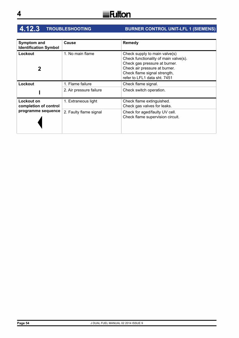
J DUAL FUEL MANUAL 02 2014 ISSUE 9Page 54
4
Symptom and Identification Symbol
Cause Remedy
Lockout 1. No main flame Check supply to main valve(s) Check functionality of main valve(s).Check gas pressure at burner.Check air pressure at burner.Check flame signal strength,refer to LFL1 data sht. 7451
2
Lockout 1. Flame failure Check flame signal.
l 2. Air pressure failure Check switch operation.
Lockout on completion of control programme sequence
1. Extraneous light Check flame extinguished.Check gas valves for leaks.
2. Faulty flame signal Check for aged/faulty UV cell.Check flame supervision circuit.
4.12.3 TROUBLESHOOTING BURNER CONTROL UNIT-LFL 1 (SIEMENS)

J DUAL FUEL MANUAL 02 2014 ISSUE 9 Page 55
4
Problem Cause RemedyIgnition Failure 1. Oil Tank Empty Refill the oil tank. A slight delay in the re-priming of
the fuel pump may cause the burner programmer to require resetting before the boiler operates satisfactorily.
2. Power Supply Check fuse or Circuit breaker. Reset or replace as required.
3. Ignition Electrodes Check electrodes for carbon build-up, clean if required. Check settings adjust if required. Check for cracks in porcelain, if found, replace.
4. Transformer Check voltage between transformer leads at terminal block to be sure transformer is live.
5. UV Detector Check for ignition interference. 6. Loose wire connection Check connections to all components.
7. Burner Control Check voltage between pilot terminal and neutral and ignition terminal and neutral. Check must be made before control locks out on safety. If no power, replace control.
8. Oil nozzle clogging Check oil nozzle(s), clean or replace as necessary.
9. Faulty Oil Pump Check to see if oil is being pumped to the boiler nozzle. Repair or replace as necessary.
Flame Failure (see note)
1. Power Supply Check fuse or Circuit breaker. Reset or replace as required.
2. Ignition Electrodes Check electrodes for carbon build-up, clean if required. Check settings adjust if required. Check for cracks in porcelain, if found, replace.
3. Main Air Adjustment Check air adjustment. Air may be blowing flame away from the UV detector. Open primary air until fire brushes the furnace wall.
4. UV Scanner Check for dirt on scanner, clean as required. Check for proper location of detector.
5. Contact open on Adjust to proper setting air safety switch.6. Scanner wiring reversed at panel Change to correct terminals.
` 7. Oil Supply Check oil level in supply tank, ensure it is not below intake line. Fill tank with oil. Check for clogged nozzle. Clean or replace. Check oil filter and replace if necessary.
8. Oil Valve Check the voltage between oil valve neutral at terminal block to be sure oil valve is getting power.
9. Oil Pump Check for clogged strainer or filter. Remove and clean. Check for slipping or broken coupling. Tighten or replace. Check for seized pump shaft. Replace.
10. Loss of Oil Prime Check all lines for possible air leak in intake line and tighten. Check the intake line is not restricted. Replace.
4.12.4 TROUBLESHOOTING OIL BOILER

J DUAL FUEL MANUAL 02 2014 ISSUE 9Page 56
4
4.12.4 TROUBLESHOOTING, CONTINUED. OIL BOILER
Problem Cause RemedyBoiler fails to start
1. No Power Check fuse or circuit breaker. Reset or replace as necessary.
2. Pressure Control Disconnect all power to the controller. Disconnect the wires from the controller. connect an ohmmeter between the switch terminals. Lower the set point of the controller, the switch should make. raise the set point and re-check, switch should break. if the controller operates improperly, replace it.
Burner Cut-off 1. Oil tank empty Refill the oil tank. A slight delay in the re-priming of the fuel pump may cause the burner programmer to require resetting before the boiler operates satisfactorily.
2. Power Supply Check fuse or Circuit breaker. Reset or replace as required.
3. Ignition Electrodes Check electrodes for carbon build-up, clean if required. Check settings adjust if required. Check for cracks in porcelain, if found, replace.
4. UV Detector Check for dirt on detector, clean as required. Check for proper location of detector.
5. Faulty Air Switch Check for faulty air switch by jumpering the two air switch leads at the terminal block. If the boiler starts and runs with the jumper in place, the air switch should be replaced.
6. Faulty Level Control Check the level control relays are securely mounted on their bases. Check the power supply to each. The relays may be checked by swopping positions and checking they are both functioning.
7. Oil Nozzle Check for clogged nozzle, clean or replace.
8. Transformer Check voltage between transformer neutral at terminal block to be sure transformer is being powered.
9. Burner Control Check voltage between pilot terminal and neutral and ignition terminal and neutral. Check must be made before the control locks out on safety. If no power replace control.
10. Pressure Control Disconnect all power to the controller. Disconnect the wires from the controller. Connect an ohmmeter between the switch terminals. Lower the set point of the controller, the switch should make raise the set point and re-check, switch should break. If the controller operates improperly, replace it.
Note: One of the most common causes of flame failure is dirt/sediment in the oil filter, oil lines, solenoid valves or nozzle, caused by a new delivery of oil. If the oil tank level is allowed to fall near to the bottom of the tank it is highly probable that sediment on the bottom of the tank will be disturbed and mixed in with the new oil delivery, especially if the delivery rate is too fast.

J DUAL FUEL MANUAL 02 2014 ISSUE 9 Page 57
4
4.12.4 TROUBLESHOOTING, CONTINUED. OIL BOILER
Problem Cause RemedyPoor Combustion
1. Refractory Bricks Check the bricks are not plugged with soot or broken into pieces. Clean and replace as required.
2. Stainless Steel Ring Check to ensure the ring is present and fits securely against the furnace wall.
3. Main Air Adjustment Check air adjustment. Open main air until fire brushes the furnace wall.
4. Secondary Air Adjustment. Check main air adjustment to see if it has moved. Adjust as necessary and tighten in position. Check CO2 and O2 level.
5. Draft Check draft is neutral. Consider installing a barometric damper if the draft is too strong.
6. Dirty Flue Check flue for Carbon build-up or blockage. Clean flue passages with brush.
7. Negative Room Pressure Ensure no exhaust fans are running in the boiler room.
8. Oil Nozzle Check for blocked nozzle, clean or replace as necessary.
9. Oil Pump Check for blocked strainer or filter. Remove or clean. Check for slipping or broken coupling. Tighten or replace. Check for seized pump shaft. Replace.
Burner back fires
1. Refractory Bricks Check the bricks are not plugged with soot or broken into pieces. Clean and replace as required.
2. Ignition Electrodes Check electrodes for carbon build-up, clean if required. Check settings adjust if required. Check for cracks in porcelain, if found, replace.
3. UV Detector Check for dirt on scanner, clean as required. Check for proper location of detector.
4. Draft Problem Check draft is neutral. Consider installing a barometric damper if the draft is too strong.
5. Negative Room Pressure Ensure no exhaust fans are running in the boiler room.
6. Primary Air Adjustment Check air adjustment. Air may be blowing fire away from flame detector.
7. Oil Valve(s) Check for leaking oil valve(s) and replace. 8. Loss of Oil Prime Check all lines for possible air leak in intake line
and tighten. Check for possible restricted intake line. Replace.
9. Loose Oil Fittings Check all fittings and tighten. 10. Blocked Oil Filter Check and clean or replace. 11. Blocked Screen In Oil Pump Check and clean or replace. 12. Blocked Flue Check flue is not blocked, clean as required.
Check draft at flue. 13. Vacuum On Pump Check for too high a vacuum on the pump.
Check oil lines and distance from tank to boiler. Repair or replace as necessary.
14. Hole In Suction Line Check and replace as necessary.

J DUAL FUEL MANUAL 02 2014 ISSUE 9Page 58
4
Problem Cause Remedy Boiler will not maintain pressure
1. Oil Tank Empty Refill the oil tank. A slight delay in the re-priming of the fuel pump may cause the burner programmer to require resetting before the boiler operates satisfactorily.
2. Oil Nozzle Check for blocked nozzle. Clean or replace.3. Oil Valve Check voltage between oil valve leads at terminal
block to be sure oil valve is getting power. 4. Oil Pump Check for blocked strainer or filter. Remove and
clean. Check for slipping or broken coupling, tighten or replace. Check for seized pump shaft. Replace the pump.
5. Dirty Flue Check flue for Carbon build-up or blockage. Clean flue passages with brush.
6. Pressure Control Disconnect all power to the controller. Disconnect the wires from the controller. Place an OHM meter between the switch terminals. Lower the set point of the controller, the switch should make. Raise the set point and recheck, switch should break. If the controller operates improperly, replace it.
7. Scale Buildup In Boiler Consult Fulton. 8. Refractory Bricks Check the bricks are not plugged with soot,
cracked or broken into pieces. Clean and replace as required.
9. Steam Traps Blowing Through Check traps, clean or replace as required. 10. Boiler Size Boiler may be under sized.
4.12.4 TROUBLESHOOTING, CONTINUED. OIL BOILER

J DUAL FUEL MANUAL 02 2014 ISSUE 9 Page 59
4
Problem Cause RemedyBoiler is Surging 1. Steam Traps blowing through. Check traps, clean or replace as required.
2. Scale buildup or lime deposits. Call water treatment company and consult the factory.
3. Too much water treatment Dump the return tank and flush the system. Test the water treatment.
4. Too much of a load. Check total equipment load against the boiler output. Decrease amount of equipment being used.
Boiler Rumbles 1. Draft Problem Check draft is neutral. Consider installing a barometric damper if the draft is too strong.
2. Too much main air. Adjust main air.
3. Air or water in the oil. Check tank and lines for water or leaks.
Boiler pushing steam
1. Steam Traps Check traps. Clean or replace as required.
2. Too much water treatment. Dump the return tank and flush the system. Test the water treatment.
Pump will not cut off
1. Dirty Probes. Clean or replace as required
2. Relay failed. Check relay is secure on its base, if so, replace the relay.
3. Earth connection. Check for tightness and clean.
Pump runs but does not put water in the boiler
1. Vapour locking of pump. Allow system to cool down, check steam traps of pump. and check to be sure return lines are not insulated. Check return tank temperature, if it is above 82OC vapour locking of the pump will occur. Inspect check valves. Clean and replace as needed. Replace pump with multi-stage centrifugal pump able to cope with 121OC.
2. Blocked feed water line Check feed water line is not blocked, clean as required.
Water pump runs intermittently
1. Scale on probes. Check probes, clean as required.
2. Bad pump contactor. Check to ensure the contactor is live. Check to ensure the contactor coil is being pulled in. Replace as required.
3. Pump Motor damaged. Check the pump circuit is live. If the circuit is live but the pump is not running, replace the pump.
Boiler continues after shut down
1. Oil Valve defective Check the valve is opening and closing.
Oil fumes coming out around the oil pump housing
1. Bad draft condition Check the draft with a gauge, should read neutral. May need to install a barometric damper.
2. Venting of room Ensure the boiler room doors are closed on shut down and the recommended vents are clear.
Boiler flooding 1. Pump does not shut off. Dirty probes, clean or replace as required. 2. Relay failed. Check relay is secure on its base, if so replace the relay.
3. Earth connection. Check for tightness and clean.
4. Vacuum created with the boiler off. As the boiler cools it pulls water from the system. To prevent this, add an anti-vacuum valve on the steam gauge assembly piping, this valve closes under pressure and opens under vacuum.
4.12.4 TROUBLESHOOTING, CONTINUED. OIL BOILER

J DUAL FUEL MANUAL 02 2014 ISSUE 9Page 60
4
FIG. 34 FAULT FINDING CHECK LIST
Ignition Failure
Flame Failure
Burner Cutoff
Poor Combustion
Burner Back Fires
Boiler will not
Maintain Pressure
Boiler will not
Maintain Water
Supply
Oil Supply
Refractories
S.S. Ring
Ignition Electrodes
Oil Nozzle
Main Air Adjustment
Oil Valves
Oil Pump
Photoelectric Cell
Low Water Probes
Low Water Control
Pressure Controller
Burner Programmer
Draught
Transformer
Sec. Air Adjustment
Loss of Priming Oil
Steam Overload
Feedwater Pump
Bad Traps
Dirty Flues
Fault Cause

J DUAL FUEL MANUAL 02 2014 ISSUE 9 Page 61
4
This log should be completed regularly as a record of boiler maintenance.
4.13 MAINTENANCE LOG
Date Action Remarks Sig.

J DUAL FUEL MANUAL 02 2014 ISSUE 9Page 62
4Ve
rtica
l Ste
am B
oile
r - D
aily
and
Wee
kly
Test
sBo
iler N
umbe
r:
Mod
el:
Fuel
:
Day
12
34
56
7
Date
1.
Visu
al In
spec
tion
of p
ipew
ork
and
fittin
gs fo
r sig
ns o
f lea
kage
Y - N
Y - N
Y - N
Y - N
Y - N
Y - N
Y - N
2.
Pum
p Ch
eck,
Fee
d pu
mp,
sta
rt/st
opY
- NY
- NY
- NY
- NY
- NY
- NY
- N
3.
Firs
t Low
Wat
er L
evel
, Bur
ner c
ut-o
ut a
nd a
larm
sou
ndY
- NY
- NY
- NY
- NY
- NY
- NY
- NNo
te: *
Addi
tiona
l tes
ts to
be
com
plet
ed o
n th
e 7t
h da
y
4.
Seco
nd L
ow W
ater
Lev
el, B
urne
r cut
-out
ala
rm s
ound
.Y
- NY
- NY
- NY
- NY
- NY
- NY
- N*1
0. F
lam
e fa
ilure
dev
ice
test
ed.
Y - N
5.
Blow
dow
n, B
oile
rD
urat
ion
seco
nds.
Self
Mon
itorin
g Co
ntro
ls (i
f fitte
d)Te
st T
ime.
6.
Blow
dow
n, W
ater
Col
umn
Dur
atio
n se
cond
s.*1
1. F
irst L
ow W
ater
Lev
el
Burn
er c
ut-o
ut a
nd a
larm
sou
ndY
- N
Test
Tim
e.
7.
Blow
dow
n, W
ater
Lev
el G
auge
Dur
atio
n se
cond
s.*1
2. S
econ
d Lo
w W
ater
Lev
el
Burn
er c
ut-o
ut a
larm
sou
ndY
- N
Test
Tim
e.
Pres
sure
gau
ge re
adin
g fo
r blo
wdo
wn
test
s.*1
3. P
ress
ure
gaug
e re
adin
g.
Boile
r wat
er a
nd w
ater
trea
tmen
t val
ues
mus
t be
w
ithin
kno
wn
tole
ranc
es o
f the
dat
um.
8.
Boile
r Wat
er.
datu
m v
alue
.TD
S.re
adin
g
datu
m v
alue
.PH
read
ing
9.
Wat
er T
reat
men
t.da
tum
val
ue.
read
ing
Ope
rato
r Sig
natu
re:
Test
Res
ults
and
act
ions
take
n
Day
1.si
g.D
ay5.
sig.
2.si
g.6.
sig.
3.si
g.7.
sig.
4.si
g.7+
.si
g.
Log
exam
ined
by:
Dat
e:
4.14 DAILY AND WEEKLY TEST LOG

J DUAL FUEL MANUAL 02 2014 ISSUE 9 Page 63
5
SECTION 5 - GENERAL DATA
FIG. 35 BOILER DIMENSIONS
Dimensions mmDimensions are approximate and only intended as a guide to aid installation
MODEL: J SERIES 6J/8J/10J 15J 20J 30J 40J/50J/60JA Minimum Clearance 2300 2400 2600 2800 3100B Overall Width 980 1030 1250 1440 1655C Overall Depth 1025 1060 1400 1595 1850D Overall Height 1745 1835 1990 2170 2440E Boiler Height 1670 1760 1890 2070 2320F Boiler Diameter 715 765 985 1175 1390G Height to Top of Fan 1810 1900 2030 2210 2460H Gas Train Length 425 555 555 570 940J Gas Inlet Height 2045 2165 2330 2510 2820K Oil Inlet Height 1550 1640 1735 1915 2150L Safety Valve Discharge Height 1840 1930 2060 2240 2490M Steam Outlet Height 1845 1950 2100 2310 2680N Feedwater Inlet Height 1810 1900 2030 2210 2460P Flue Outlet Height 1500 1565 1670 1820 2075R Flue Diameter 152 203 255 305 305S Main Boiler Blowdown Height 380 380 390 390 395T Control Column Blowdown Height 1025 1115 1245 1385 1670
U Water Level Gauge (Sight Glass) Blowdown Height 1060 1155 1285 1465 1710
V Water Level Gauge Stand Off 265 265 265 265 265W Control Column Stand Off 270 270 270 270 265X Fan Stand Off 330 330 440 480 500
5.1 BOILER DIMENSIONS
Note: * Recommended height for service & maintenanceInformation from TI 117 Issue 7
360°
AL
UT
JM
ED
NP
S
H
X
GK
V
W
B
C
R
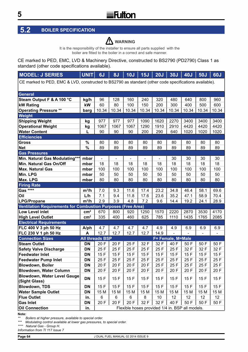
J DUAL FUEL MANUAL 02 2014 ISSUE 9Page 64
5
! WARNING It is the responsibility of the installer to ensure all parts supplied with the
boiler are fitted to the boiler in a correct and safe manner.
CE marked to PED, EMC, LVD & Machinery Directive, constructed to BS2790 (PD2790) Class 1 as standard (other code specifications available).
5.2 BOILER SPECIFICATION
Note: ** Boilers at higher pressure, available to special order.*** Modulating control available at lower gas pressures, to special order.**** Natural Gas - Group H.Information from TI 117 Issue 7
MODEL: J SERIES UNIT 6J 8J 10J 15J 20J 30J 40J 50J 60JCE marked to PED, EMC & LVD, constructed to BS2790 as standard (other code specifications available).
GeneralSteam Output F & A 100 °C kg/h 96 128 160 240 320 480 640 800 960kW Rating kW 60 80 100 150 200 300 400 500 600Operating Pressure ** barg 10.34 10.34 10.34 10.34 10.34 10.34 10.34 10.34 10.34WeightShipping Weight kg 977 977 977 1090 1620 2270 3400 3400 3400Operational Weight kg 1067 1067 1067 1290 1910 2910 4420 4420 4420Water Content L 90 90 90 200 290 640 1020 1020 1020EfficienciesGross % 80 80 80 80 80 80 80 80 80Net % 89 89 89 89 89 89 89 89 89Gas PressuresMin. Natural Gas Modulating*** mbar - - - - - 30 30 30 30Min. Natural Gas On/Off mbar 18 18 18 18 18 18 18 18 18Max. Natural Gas mbar 100 100 100 100 100 100 100 100 100Min. LPG mbar 50 50 50 50 50 50 50 50 50Max. LPG mbar 80 80 80 80 80 80 80 80 80Firing RateGas **** m3/h 7.0 9.3 11.6 17.4 23.2 34.8 46.4 58.1 69.6Oil L/h 7.1 9.4 11.8 17.6 23.6 35.2 47.1 58.9 70.4LPG/Propane m3/h 2.9 3.9 4.8 7.2 9.6 14.4 19.2 24.1 28.9Ventilation Requirements for Combustion Purposes (Free Area)Low Level inlet cm2 670 800 920 1250 1570 2220 2870 3530 4170High Level Outlet cm2 335 400 460 625 785 1110 1435 1765 2085Electrical RequirementsFLC 400 V 3 ph 50 Hz A/ph 4.7 4.7 4.7 4.7 4.9 4.9 6.9 6.9 6.9FLC 230 V 1 ph 50 Hz A 12.7 12.7 12.7 12.7 14.9 - - - -Connection Sizes All threads BSP F= Female, M=MaleSteam Outlet DN 20 F 20 F 25 F 32 F 32 F 40 F 50 F 50 F 50 FSafety Valve Discharge DN 25 F 25 F 25 F 25 F 25 F 25 F 32 F 32 F 32 FFeedwater Inlet DN 15 F 15 F 15 F 15 F 15 F 15 F 15 F 15 F 15 FFeedwater Pump Inlet DN 25 F 25 F 25 F 25 F 25 F 25 F 25 F 25 F 25 FBlowdown, Boiler DN 20 F 20 F 20 F 20 F 25 F 25 F 25 F 25 F 25 FBlowdown, Water Column DN 20 F 20 F 20 F 20 F 20 F 20 F 20 F 20 F 20 FBlowdown, Water Level Gauge (Sight Glass) DN 15 F 15 F 15 F 15 F 15 F 15 F 15 F 15 F 15 F
Blowdown, TDS DN 15 F 15 F 15 F 15 F 15 F 15 F 15 F 15 F 15 FWater Sample Outlet DN 15 M 15 M 15 M 15 M 15 M 15 M 15 M 15 M 15 MFlue Outlet in. 6 6 6 8 10 12 12 12 12Gas Inlet DN 20 F 20 F 20 F 32 F 32 F 40 F 50 F 50 F 50 FOil Connection in. Flexible hoses provided 1/4 in. BSP all models.

J DUAL FUEL MANUAL 02 2014 ISSUE 9 Page 65
5
5.3 RECOMMENDED WATER CONDITIONS
IMPORTANT
It is very important that a strict water management program is followed to ensure trouble free boiler operation.
The following are recommended for feedwater and for boiler water
mg/kg = Milligrams per KilogramCaCO3= Calcium CarbonatePO4 = PhosphateSiO2 = Silicon Dioxide
1 Grain hardness = 17.118 ppmtherefore 70 ppm = 4.10 grains hardness.
For practical purposes mg/kg = ppm
It is critical that the boiler water pH be alkaline in the range 10.5 -12.0 Daily boiler blowdown is essential to help prevent formation of deposits and reduce Total Dissolved Solids (TDS).
Consult your Water Treatment specialist to establish the frequency and duration of blowdown required to achieve the required conditions.
FEEDWATER (water entering boiler) pH Value 8.5 to 9.5 tested at room temperature. Hardness less than 2.0 mg/kg in the form of CaCO3. Suspended Solids None. Chloride Less than 50 mg/kg.Organic Matter Less than 5 mg/kg. Oil None. Minimum Temperature 85°C
BOILER WATER (water inside boiler) pH Value 10.5 - 12.0, tested at room temperature. Hardness Not detectable. Suspended Solids Less than 200 mg/kg. Chloride Less than 500 mg/kg. Oxygen Scavenger, Sodium Sulphite or Tannin 30 to 70 mg/kg. Phosphate Less than 50 mg/kg, in the form of PO4.
Total Alkalinity Less than 1000 mg/kg. Caustic Alkalinity 300 mg/kg as minimum as CaCO3.
Total Dissolved Solids (TDS) Less than 3500 ppm. Iron Less than 1 mg/kg. Silica Less than 150 mg/kg, in the form of SiO2.
Dissolved Oxygen None.
!

J DUAL FUEL MANUAL 02 2014 ISSUE 9Page 66

J DUAL FUEL MANUAL 02 2014 ISSUE 9
A
Page 67
FIG. 36 WATER LEVEL PROBE COMPONENTS
The “Terminal & Securing Nuts” are tightened to a specified torque during manufacture which causes the “PTFE Insulation” to seal against the probe body. Therefore these nuts must not be adjusted because the seal will be broken which may cause the probe to leak. (See FIG. 36)
“Angle Rajah” ONLY must be used to connect wire to the probes because they clip directly to the “Terminal Nut”. Spade Connectors must NOT be used because the “Terminal Nut” would require adjustment and therefore cause the probe to leak. (See FIG. 37)
N.B. The “Probe Rod Grub Screw and Lock Nut” are suitably tightened during manufacture, meaning the probe is ready to be installed without any adjustment.
The ONLY instance a spanner should be used, is to turn the “Probe Body” in order to remove or reinstall the entire probe.
! IMPORTANTu Terminal & Securing Nuts must not be adjusted.
u Only Angle Rajah are to be used to connect wire to the probes.
FIG. 37 ANGLE RAJAH FITTED TO PROBE
APPENDIX A WATER LEVEL PROBE INFO
Terminal nut
Probe body
Probe rod
Securing nuts
PTFEInsulation
Probe rodgrub screw
Probe rodlock nut
Terminal nut
Angle rajah
Probe body
Probe wire

J DUAL FUEL MANUAL 02 2014 ISSUE 9Page 68

J DUAL FUEL MANUAL 02 2014 ISSUE 9
B
Page 69
The Fulton motorised high/low control is designed to improve the efficiency of the boiler by switching the firing rate from high fire (when there is low steam pressure in the boiler) to low fire (when the boiler reaches a high steam pressure). The systems major components comprises of; two stage gas valves, motorised air damper unit and two stage steam pressure switches.
Air Damper Motor
High/Low Fire Cams
Air Damper Housing
With the steam pressure switch preset to the high and low fire operational requirements of the system, and the boiler operating normally, steam pressure will gradually increase until the high pressure limit is reached, the pressure switch will then switch the two stage gas valve and the air damper motor to the low fire position.
The boiler will continue to operate at low fire until the steam pressure falls to the low pressure limit setting on the pressure switch. At this point, the gas valve and the air damper will switch the boiler into high fire mode and the sequence of high fire / low fire is regulated automatically with no routine maintenance required.
Note: Should the boiler attain the off setting of the on/off control pressure switch, the burner will switch off on low fire and then restart in the normal way on high fire.
APPENDIX B MOTORISED HIGH / LOW CONTROL
! CAUTIONThe adjustment of the air gate control motor or the two stagegas valve should only be carried out by qualified personnel,incorrect adjustment could result in damage to the pressurevessel and/or the production of harmful combustion gases.
1.1 GENERAL
1.2 OPERATION
1.3 ADDITIONAL CONTROLS
Low Fire Hold Switch - Used to maintain the boiler in the low fire mode during commissioning.
FIG. 38 HIGH/LOW CONTROL

J DUAL FUEL MANUAL 02 2014 ISSUE 9
B
Page 70
Commissioning should be carried out by a qualified Fulton Service Engineer.
To achieve the ideal combustion efficiency and gas input rates, a gas flow rate meter is required to measure the fuel input to the boiler.
Blue cam N7 not used
Red cam N6
Red cam N5
Red cam N4 not used
Red cam N3 not used
Yellow cam N2
Yellow cam N1
Model 6 8 10 15 20 30 40 50 60Low Firem3/h 3.5 4.7 5.8 8.7 11.6 11.6 23.2 29.0 34.8ft3/min. 2.1 2.8 3.4 5.1 6.9 10.3 13.7 17.1 20.5High Firem3/h 7.0 9.3 11.6 17.4 23.2 34.8 46.4 58.1 69.6ft3/min. 4.1 5.5 6.8 10.2 13.7 20.5 27.3 34.2 41.0
Note: Boilers are pre-commissioned before leaving the factory to ensure optimum gas input rates and combustion values.
Terminal Position DegreesN1 High Fire Motor Cam 45°N2 Low Fire Motor Cam 10°N5 High Fire Interlock Cam 40°N6 Low Fire Interlock Cam 15°
1.4 COMMISSIONING
1.4.1 FUEL INPUT RATES
1.4.2 AIR DAMPER MOTOR - FACTORY CAM SETTINGS (see 2.3 Setup procedure)
Note: The high fire interlock cam should always be set approximately 5° lower than the high fire cam position.The low fire interlock cam should always be set approximately 5° higher than the low fire cam position.
FIG. 39 AIR DAMPER MOTOR

J DUAL FUEL MANUAL 02 2014 ISSUE 9
B
Page 71
1. Set the cams on the air damper motor to the initial position. Start the boiler and wait until the motor and gas valve have driven to high fire. Adjust the main (primary) air gate to achieve the best combustion with the least buffeting in the furnace.
2. Using the low fire hold switch, hold the boiler in low fire. The air damper motor should move to its low fire position and the high fire light on the control panel should extinguish, indicating the gas and air input rates have been reduced to approximately half the high fire input rate.
Note: If gas flow rate equipment is available, the low fire gas input rate should be adjusted to the correct value (see fuel input rates table) by rotating the black 1st stage partial adjustment ring located below the 2nd stage solenoid.
3. The ideal low fire CO2 constituent of the flue gases is 8 - 10.5%. Place an exhaust gas analyser into the flue, reduce or increase the amount of air entering the boiler as required, by adjusting the low fire cam (N2) position.
Note: The reaction of the motor to a change in cam positions is:
Reduced air: adjust the cam to reduce the amount of air entering the boiler, the reaction of the motor will be immediate.
Increased air: adjust the cam to increase the amount of air entering the boiler, switch the low fire hold switch off. When the motor has driven back to high fire turn the low fire hold switch on, the damper will drive back to its new low fire position. Adjust the cams until the correct CO2 figure is achieved.
Note: Any adjustment to the cam positions requires an adjustment to its interlock cam position.
4. Switch off the low fire hold switch.
Note: if gas flow rate equipment is available, the high fire gas input rate can now be set (see fuel input rates table) by adjusting the pressure control screw located under a protective cover on the black electrical connection block.
5. The high fire CO2 constituent of the flue gases is 10 - 10.5%. Place an exhaust gas analyses into the flue, reduce or increase the amount of air entering the boiler as required, by adjusting the high fire cam (N1) position. To reduce the amount of high fire air, the damper will have to be driven to its low fire position and back again, before it takes up its new position. Ensure that the high fire interlock cam N5 is always set approximately 5° below the high fire motor position cam N1. Record all cam settings and the high and low fire final gas elbow pressures for future reference.
6. Adjust the pressure switch (PS2) to the high/low switch over point.
Part No. Description Qty Model13195 Transformer, ZT931 1 40 - 6011643 Switch, air pressure 1 40 - 6014485 Motor, damper, A30 045Y 1 40 - 6012075 Fan 1 40 - 6014489 Coupling, air gate 1 40 - 60
1.4.3 SETUP PROCEDURE
1.5 SPARE PARTS
J DUAL FUEL MANUAL 02 2014 ISSUE 9Page 72

J DUAL FUEL MANUAL 02 2014 ISSUE 9
C
The daily testing of boiler water level controls is a mandatory requirement as defined in the Health & Safety Executive Guidance Note BG01, Arrangements 2 and 3.The level of supervision is dependent upon the type of level controls (limiters) fitted.Boilers fitted with self monitoring high integrity controls (limiters) should be tested daily by a qualified boiler attendant, but may be supervised during the silent hours and weekends by a competent person trained to respond to an alarm.
Daily testing of the controls is required which can be by simulation, with a weekly test by interrupting the feedwater pump and lowering the water by evaporation.
1.1 DAILY TESTS
With the burner firing:
1. Press and hold the 1st Low Water test button 5 - 6 seconds, the Low Water alarm sounds, and the Low Water indicator lamp illuminates, and the burner shuts down.
2. Release the test button.
3. After approximately 17 seconds the Low Water alarm will cancel, the Low Water lamp will extinguish, and the burner will restart
1.1.1 1ST LOW WATER DAILY
1.1.2 2ND LOW WATER DAILY
With the burner firing:
1. Press and hold the 2nd Low Water test button for 5 - 6 seconds, the Low Water alarm sounds, and the 2nd Low Water Reset switch illuminates, and the burner shuts down.
2. Release the test button.
3. After approximately 17 seconds the 2nd Low Water Relay will reset.
4. To cancel the 2nd Low Water level alarm and light, depress the 2nd Low Water Reset switch.
The burner will restart.
APPENDIX C SPIRAX HIGH INTEGRITY LEVEL CONTROLS

J DUAL FUEL MANUAL 02 2014 ISSUE 9
C
Pump Interrupt Switch
FIG. 40 CONTROL PANEL SIDE
Note: These tests can be carried out consecutively, however it is possible that if the boiler is under load conditions the 2nd Low Water alarm will occur immediately after the burner has shut down on 1st Low Water, without the apparent loss of any more water. The reason is the collapse of the steam bubbles at the water level surface when the heat is removed. The degree of collapse could be such that the water level will disappear from the bottom of the sight glass before the alarm sounds. Should this happen, the 2nd Low Water Level alarm should be checked by lowering the water level slowly by partially opening the main blowdown valve.
With the burner firing:
1. Switch the Pump Interrupt switch to the Pump Interrupt position.
2. By evaporation lower the water level in the boiler until the 1st Low Water alarm sounds and the Low Water indicator lamp illuminates, and the burner shuts down.
3. Switch the Pump Interrupt switch to the Pump On position.
4. The pump will start and restore the water level to the normal position and switch off.
5. After approximately 17 seconds from restoring the 1st Low Water level the Low Water alarm will cancel, the Low Water lamp will extinguish, and the burner will restart.
1.2 WEEKLY TESTS (IN ADDITION)
1.2.1 1ST LOW WATER WEEKLY (IN ADDITION)
1.1.2 2ND LOW WATER WEEKLY (IN ADDITION)
With the burner firing:
1. Switch the Pump Interrupt switch to the Pump Interrupt position
2. By evaporation lower the water level in the boiler until the Low Water alarm sounds, the 2nd Low Water Reset switch illuminates, and the burner shuts down.
3. Switch the Pump Interrupt switch to the Pump On position.
4. The pump will start and restore the water level to the normal position and switch off.
5. After approximately 17 seconds from restoring the 2nd Low Water level the 2nd Low Water Relay can be reset.
6. To cancel the 2nd Low Water Level alarm and light, depress the 2nd Low Water Reset switch.
7. The burner will restart.

J DUAL FUEL MANUAL 02 2014 ISSUE 9 Page 75
Material & Workmanship Warranty
General Warranty
The Fulton general Guarantee is given in lieu of and in exclusion of any warranty expressed or implied, statutory or otherwise, as to the state, condition, performance, quality or fitness of the goods. Save thereunder we shall be under no obligation or liability of any kind to you in regard to the goods. In the case of new goods manufactured and supplied by us we will make good any defect developing therein under proper use within 12 months of delivery, provided that after investigation in our sole discretion we are satisfied that the defect arose from faulty design, materials or workmanship and from no other cause whatsoever.
Defective goods or parts must be returned to us as soon as possible after discovery of the defect, Costs of carriage and of detaching and incorporating parts will be borne by you. In all cases at the termination of such 12 months all liability on our part will cease. No liability whatsoever is to be incurred by us in respect of gauge or sight-glasses, packing glands or electric motors or any goods or accessories not of our manufacture. But so far as we are able, we shall let you have the benefit of any guarantee or warranty given to us in respect thereof.
Fulton Ltd
Fulton Ltd will repair or replace EXW factory any Fulton pressure vessel which within five (5) years of the date of delivery is found to be defective in workmanship, or material, provided this equipment is operated and maintained by the buyer for the purpose for which it was designed
and in accordance with the Manufacturer’s Handbook. This Warranty does not cover damage or failures that can be attributed to corrosion, scale or dirt accumulation or to low water conditions.
This Warranty is good only in the United Kingdom of Great Britain and Northern Ireland. This Warranty does not include labour or delivery charges of any kind.
5 YearWarranty
On the Fulton Boiler Pressure Vessel

J DUAL FUEL MANUAL 02 2014 ISSUE 9
FM 28400
003
Fulton Ltd5 Fernhurst RoadFishpondsBristol BS5 7FGEngland
Telephone: +44 (0) 117 972 3322Fax: +44 (0) 117 972 3358Email: [email protected]
www.fulton.co.uk
Related Documents


