Air-Cooled Scroll Chillers Model CGAM 20 to 130 Tons — Made in USA Installation, Operation, and Maintenance March 2021 CG-SVX17M-EN Model: CGAM SAFETY WARNING Only qualified personnel should install and service the equipment. The installation, starting up, and servicing of heating, ventilating, and air-conditioning equipment can be hazardous and requires specific knowledge and training. Improperly installed, adjusted or altered equipment by an unqualified person could result in death or serious injury. When working on the equipment, observe all precautions in the literature and on the tags, stickers, and labels that are attached to the equipment.

Welcome message from author
This document is posted to help you gain knowledge. Please leave a comment to let me know what you think about it! Share it to your friends and learn new things together.
Transcript

Air-Cooled Scroll Chillers
Model CGAM20 to 130 Tons — Made in USA
Installation, Operation, and Maintenance
March 2021 CG-SVX17M-EN
Model: CGAM
SAFETY WARNINGOnly qualified personnel should install and service the equipment. The installation, starting up, and servicing of heating, ventilating, and air-conditioning equipment can be hazardous and requires specific knowledge and training. Improperly installed, adjusted or altered equipment by an unqualified person could result in death or serious injury. When working on the equipment, observe all precautions in the literature and on the tags, stickers, and labels that are attached to the equipment.

Introduction
Read this manual thoroughly before operating or servicing this unit.
Warnings, Cautions, and Notices
Safety advisories appear throughout this manual as required. Your personal safety and the proper operation of this machine depend upon the strict observance of these precautions.
Important Environmental Concerns
Scientific research has shown that certain man-made chemicals can affect the earth’s naturally occurring stratospheric ozone layer when released to the atmosphere. In particular, several of the identified chemicals that may affect the ozone layer are refrigerants that contain Chlorine, Fluorine and Carbon (CFCs) and those containing Hydrogen, Chlorine, Fluorine and Carbon (HCFCs). Not all refrigerants containing these compounds have the same potential impact to the environment. Trane advocates the responsible handling of all refrigerants-including industry replacements for CFCs and HCFCs such as saturated or unsaturated HFCs and HCFCs.
Important Responsible Refrigerant Practices
Trane believes that responsible refrigerant practices are important to the environment, our customers, and the air conditioning industry. All technicians who handle refrigerants must be certified according to local rules. For the USA, the Federal Clean Air Act (Section 608) sets forth the requirements for handling, reclaiming, recovering and recycling of certain refrigerants and the equipment that is used in these service procedures. In addition, some states or municipalities may have additional requirements that must also be adhered to for responsible management of refrigerants. Know the applicable laws and follow them.
The three types of advisories are defined as follows:
WARNINGIndicates a potentially hazardous situation which, if not avoided, could result in death or serious injury.
CAUTIONsIndicates a potentially hazardous situation which, if not avoided, could result in minor or moderate injury. It could also be used to alert against unsafe practices.
NOTICE Indicates a situation that could result in equipment or property-damage only accidents.
WARNING
Proper Field Wiring and Grounding Required!
Failure to follow code could result in death or serious injury. All field wiring MUST be performed by qualified personnel. Improperly installed and grounded field wiring poses FIRE and ELECTROCUTION hazards. To avoid these hazards, you MUST follow requirements for field wiring installation and grounding as described in NEC and your local/state electrical codes.
WARNING
Personal Protective Equipment (PPE) Required!
Failure to wear proper PPE for the job being undertaken could result in death or serious injury. Technicians, in order to protect themselves from potential electrical, mechanical, and chemical hazards, MUST follow precautions in this manual and on the tags, stickers, and labels, as well as the instructions below:
• Before installing/servicing this unit, technicians
MUST put on all PPE required for the work being
undertaken (Examples; cut resistant gloves/sleeves,
butyl gloves, safety glasses, hard hat/bump cap, fall
protection, electrical PPE and arc flash clothing).
ALWAYS refer to appropriate Material Safety Data
Sheets (MSDS)/Safety Data Sheets (SDS) and OSHA
guidelines for proper PPE.
• When working with or around hazardous chemicals,
ALWAYS refer to the appropriate MSDS/SDS and
OSHA/GHS (Global Harmonized System of
Classification and Labelling of Chemicals) guidelines
for information on allowable personal exposure
levels, proper respiratory protection and handling
instructions.
• If there is a risk of energized electrical contact, arc, or
flash, technicians MUST put on all PPE in accordance
with OSHA, NFPA 70E, or other country-specific
requirements for arc flash protection, PRIOR to
servicing the unit. NEVER PERFORM ANY
SWITCHING, DISCONNECTING, OR VOLTAGE
TESTING WITHOUT PROPER ELECTRICAL PPE AND
ARC FLASH CLOTHING. ENSURE ELECTRICAL
METERS AND EQUIPMENT ARE PROPERLY RATED
FOR INTENDED VOLTAGE.
©2021 Trane CG-SVX17M-EN

Introduction
Factory Warranty Information
Compliance with the following is required to preserve the factory warranty:
All Unit Installations
Startup MUST be performed by Trane, or an authorized agent of Trane, to VALIDATE this WARRANTY. Contractor must provide a two-week startup notification to Trane (or an agent of Trane specifically authorized to perform startup).
Copyright
This document and the information in it are the property of Trane, and may not be used or reproduced in whole or in part without written permission. Trane reserves the right to revise this publication at any time, and to make changes to its content without obligation to notify any person of such revision or change.
Trademarks
All trademarks referenced in this document are the trademarks of their respective owners.
Factory Training
Factory training is available through Trane University™ to help you learn more about the operation and maintenance of your equipment. To learn about available training opportunities contact Trane University™.
Online: www.trane.com/traneuniversity
Phone: 855-803-3563
Email: [email protected]
Revision History
• Updated Drawing Number in Unit Wiring chapter.
• Added Equipment Damage - Snow, ice, or debris removal notice in the Start-Up and Shutdown chapter.
• Running edits.
WARNING
Follow EHS Policies!
Failure to follow instructions below could result in death or serious injury.
• All Trane personnel must follow the company’s
Environmental, Health and Safety (EHS) policies
when performing work such as hot work, electrical,
fall protection, lockout/tagout, refrigerant handling,
etc. Where local regulations are more stringent than
these policies, those regulations supersede these
policies.
• Non-Trane personnel should always follow local
regulations.
WARNING
Hazardous Service Procedures!
Failure to follow all precautions in this manual and on the tags, stickers, and labels could result in death or serious injury.Technicians, in order to protect themselves from potential electrical, mechanical, and chemical hazards, MUST follow precautions in this manual and on the tags, stickers, and labels, as well as the following instructions: Unless specified otherwise, disconnect all electrical power including remote disconnect and discharge all energy storing devices such as capacitors before servicing. Follow proper lockout/tagout procedures to ensure the power can not be inadvertently energized. When necessary to work with live electrical components, have a qualified licensed electrician or other individual who has been trained in handling live electrical components perform these tasks.
CG-SVX17M-EN 3

Table of Contents
Model Number Descriptions . . . . . . . . . . . . . . 7
Nameplates . . . . . . . . . . . . . . . . . . . . . . . . . . . 7
Unit Nameplate . . . . . . . . . . . . . . . . . . . . . . . 7
Compressor Nameplate . . . . . . . . . . . . . . . . 7
Model Number Coding System . . . . . . . . . . 7
Model Number Descriptions . . . . . . . . . . . . . . 8
Unit Model Number Description . . . . . . . . . 8
Compressor Model Number Description . . 9
General Information . . . . . . . . . . . . . . . . . . . . 10
Unit Description . . . . . . . . . . . . . . . . . . . . . . 10
Accessory/Options Information . . . . . . . . . 12
General Data . . . . . . . . . . . . . . . . . . . . . . . . . 14
Pre-Installation . . . . . . . . . . . . . . . . . . . . . . . . . 24
Inspection Checklist . . . . . . . . . . . . . . . . . . . 24
Unit Storage . . . . . . . . . . . . . . . . . . . . . . . . . 24
Installation Requirements . . . . . . . . . . . . . . 24
Dimensions and Weights . . . . . . . . . . . . . . . . 25
Service Clearances . . . . . . . . . . . . . . . . . . . . 25
Mounting Locations . . . . . . . . . . . . . . . . . . . 26
Unit without Wind Load Rating . . . . . . . . 26
Units with Wind Load Rating . . . . . . . . . 29
Weights . . . . . . . . . . . . . . . . . . . . . . . . . . . . . 31
Base Units . . . . . . . . . . . . . . . . . . . . . . . . . 31
Option Weights . . . . . . . . . . . . . . . . . . . . . 36
Installation - Mechanical . . . . . . . . . . . . . . . . 38
Location Requirements . . . . . . . . . . . . . . . . 38
Sound Considerations . . . . . . . . . . . . . . . 38
Wind Load Considerations . . . . . . . . . . . 38
Foundation . . . . . . . . . . . . . . . . . . . . . . . . 38
Clearances . . . . . . . . . . . . . . . . . . . . . . . . . 38
Rigging . . . . . . . . . . . . . . . . . . . . . . . . . . . . . . 38
Lifting Procedure . . . . . . . . . . . . . . . . . . . 38
Center of Gravity . . . . . . . . . . . . . . . . . . . 40
Unit Isolation and Leveling . . . . . . . . . . . . . 45
General . . . . . . . . . . . . . . . . . . . . . . . . . . . 45
Isolator Options . . . . . . . . . . . . . . . . . . . . 45
Isolator Selection and Placement . . . . . . 48
Evaporator Piping . . . . . . . . . . . . . . . . . . . . 65
Drainage . . . . . . . . . . . . . . . . . . . . . . . . . . .65
Evaporator Piping Components . . . . . . . .65
Entering Chilled Water Piping . . . . . . . . . .66
Leaving Chilled Water Piping . . . . . . . . . .66
Water Strainer . . . . . . . . . . . . . . . . . . . . . .66
Flow Switch . . . . . . . . . . . . . . . . . . . . . . . .66
Evaporator Label . . . . . . . . . . . . . . . . . . . .67
Pressure Drop Curves . . . . . . . . . . . . . . . .68
Ambient Freeze Avoidance . . . . . . . . . . . .69
Low Evap Refrigerant Cutout/Percent Glycol Recommendations . . . . . .69
Performance Adjustment Factors . . . . . . .73
Partial Heat Recovery . . . . . . . . . . . . . . . . . .74
Partial Heat Recovery Piping . . . . . . . . . . .74
Partial Heat Recovery Freeze Avoidance .75
Partial Heat RecoveryPressure Drop Curves . . . . . . . . . . . . . . . .76
Dual High Head Pump Package . . . . . . . . . .77
Pressure Drop Information - Units with Optional Pump Package . . . . .78
Pump Package Requirements . . . . . . . . . .81
Expansion Tank - Maximum Loop Volume . . . . . . . . . . . . . .82
Installation - Electrical . . . . . . . . . . . . . . . . . . . .84
General Recommendations . . . . . . . . . . . . .84
Installer-Supplied Components . . . . . . . . . .84
Power Supply Wiring . . . . . . . . . . . . . . . . .85
Control Power Supply . . . . . . . . . . . . . . . .85
Heater Power Supply . . . . . . . . . . . . . . . . .85
Partial Heat Recovery Power Supply . . . .86
Water Pump Power Supply . . . . . . . . . . . .86
Interconnecting Wiring . . . . . . . . . . . . . . . . .86
Chilled Water Flow (Pump) Interlock . . . .86
Chilled Water Pump Control . . . . . . . . . . .86
Chilled Water Pump Control —Field Supplied Dual Pumps . . . . . . . . . . . .87
Chilled Water Pump Control — Optional Pump Package . . . . . . . . . . . . . .88
Alarm and Status Relay Outputs(Programmable Relays) . . . . . . . . . . . . . . .88
4 CG-SVX17M-EN

Table of Contents
Low Voltage Wiring . . . . . . . . . . . . . . . . . 88
Emergency Stop . . . . . . . . . . . . . . . . . . . . 89
External Auto/Stop . . . . . . . . . . . . . . . . . . 89
Ice Building Option . . . . . . . . . . . . . . . . . . 89
External Chilled Water Setpoint (ECWS)Option . . . . . . . . . . . . . . . . . . . . . . . . . . . . 89
External Demand Limit Setpoint (EDLS)Option . . . . . . . . . . . . . . . . . . . . . . . . . . . . 90
ECWS and EDLS Analog Input Signal Wiring Details . . . . . . . . . . . . . . . . . . . . . . . . . . . . 90
Chilled Water Reset (CWR) . . . . . . . . . . . 90
Percent Capacity Output Option . . . . . . . 91
Communications Interface Options . . . . . 92
Tracer Communications Interface . . . . . . 92
LonTalk Communications Interface for Chillers (LCI-C) . . . . . . . . . . . . . . . . . . . . . 92
BACnet Interface (BCI-C) . . . . . . . . . . . . . 92
CGAM Operating Principles . . . . . . . . . . . . . . 93
General . . . . . . . . . . . . . . . . . . . . . . . . . . . . . 93
Base Units . . . . . . . . . . . . . . . . . . . . . . . . . 94
Pump Package Components - Optional . 96
Buffer Tank Components - Optional . . . 100
Partial Heat Recovery Components . . . 100
Refrigerant Cycle . . . . . . . . . . . . . . . . . . . . 102
Oil System Operation (CGAM) . . . . . . . . . 102
Sensor Requirements . . . . . . . . . . . . . . . . 102
Controls Interface . . . . . . . . . . . . . . . . . . . . . . 103
CH530 Communications Overview . . . . . 103
DynaView Interface . . . . . . . . . . . . . . . . . . 103
Display Screens . . . . . . . . . . . . . . . . . . . . . 104
Basic Screen Format . . . . . . . . . . . . . . . . . 104
Auto, Stop/Immediate Stop . . . . . . . . . . 104
Diagnostic Annunciation . . . . . . . . . . . . 104
Manual Override Exists . . . . . . . . . . . . . 105
Main Screen . . . . . . . . . . . . . . . . . . . . . . . . 105
Chiller Operating Mode . . . . . . . . . . . . . 105
Active Chilled Water Setpoint . . . . . . . . 105
Other Active Setpoints . . . . . . . . . . . . . . 106
Password-Protected Settings . . . . . . . . 106
Settings Screen . . . . . . . . . . . . . . . . . . . . . 106
Local Time of Day Schedule Screen . . . . 108
Lockout Screen . . . . . . . . . . . . . . . . . . . . . . .111
Reports . . . . . . . . . . . . . . . . . . . . . . . . . . . . .111
Power Up and Self Tests . . . . . . . . . . . . . .112
TechView . . . . . . . . . . . . . . . . . . . . . . . . . . . .112
Unit View . . . . . . . . . . . . . . . . . . . . . . . . .114
Diagnostics View . . . . . . . . . . . . . . . . . . .119
Configuration View . . . . . . . . . . . . . . . . .119
Software View . . . . . . . . . . . . . . . . . . . . .121
Binding View . . . . . . . . . . . . . . . . . . . . . .122
Pre-Start Checkout . . . . . . . . . . . . . . . . . . . . . .123
Start-Up and Shutdown . . . . . . . . . . . . . . . . .124
Start-Up . . . . . . . . . . . . . . . . . . . . . . . . . . . . .124
Seasonal Unit Start-Up Procedure . . . . . .124
Seasonal Unit Shutdown . . . . . . . . . . . . . .124
Sequence of Operation . . . . . . . . . . . . . . . .125
Software Operation Overview . . . . . . . .125
Power Up . . . . . . . . . . . . . . . . . . . . . . . . .126
Power Up to Starting . . . . . . . . . . . . . . . .127
Stopped to Starting . . . . . . . . . . . . . . . . .127
Normal Shutdown to Stopped . . . . . . . .128
Maintenance . . . . . . . . . . . . . . . . . . . . . . . . . . .129
Recommended Maintenance . . . . . . . . . . .129
Weekly . . . . . . . . . . . . . . . . . . . . . . . . . . . .129
Monthly . . . . . . . . . . . . . . . . . . . . . . . . . . .129
Annual . . . . . . . . . . . . . . . . . . . . . . . . . . . .129
Refrigerant and Oil Charge Management 130
Lubrication System . . . . . . . . . . . . . . . . . . .130
Oil Level . . . . . . . . . . . . . . . . . . . . . . . . . .130
Oil Testing . . . . . . . . . . . . . . . . . . . . . . . . .130
Condenser Maintenance . . . . . . . . . . . . . . .131
Microchannel Condensers . . . . . . . . . . . .131
Round Tube Plate Fin Condensers . . . . .131
Evaporator Maintenance . . . . . . . . . . . . . .132
Water Strainer Maintenance . . . . . . . . . .132
Pump Package Maintenance . . . . . . . . . . .133
Rust Prevention . . . . . . . . . . . . . . . . . . . .133
Diagnostics . . . . . . . . . . . . . . . . . . . . . . . . . . . .134
Main Processor Diagnostic . . . . . . . . . . . .135
Sensor Failure Diagnostics . . . . . . . . . . . .141
CG-SVX17M-EN 5

Table of Contents
Communication Diagnostics . . . . . . . . . . 143
Main Processor- Boot Messages and Diagnos-tics . . . . . . . . . . . . . . . . . . . . . . . . . . . . . . . . 147
Unit Wiring . . . . . . . . . . . . . . . . . . . . . . . . . . . 148
Log and Check Sheet . . . . . . . . . . . . . . . . . . . 149
6 CG-SVX17M-EN

CG-SVX17M-EN 7
Model Number Descriptions
Nameplates
The CGAM unit nameplates are applied to the exterior surface of the control panel door for 20-70 Ton sizes. The 80-120 Ton sizes have a nameplate on a support beam to the right side of the starter panel.
A compressor nameplate is located on each compressor.
See Figure 1.
Unit Nameplate
The unit nameplate provides the following information:
• Unit model and size descriptor.
• Unit serial number.
• Identifies unit electrical requirements.
• Lists correct operating charges of R-410A and refrigerant oil.
• Lists unit design pressures.
• Identifies installation, operation and maintenance and service data literature.
• Lists drawing numbers for unit wiring diagrams.
Compressor Nameplate
The compressor nameplate provides the following information:
• Compressor model number.
• Compressor serial number.
• Compressor electrical characteristics.
• Utilization Range.
• Recommended refrigerant.
Model Number Coding System
The model numbers for the unit and the compressors are comprised of numbers and letter which represent features of the equipment.
See “Unit Model Number Description,” p. 8 and “Compressor Model Number Description,” p. 9 for details.
Each position, or group of positions, in a number or letter is used to represent a feature. For example, from the chart, we can determine that the letter “F” in digit 8 of the unit model number indicates unit voltage is 460/60/3.
Figure 1. Unit and compressor nameplates
CGAM Compressor Nameplate
CGAM Unit Nameplate

Model Number Descriptions
Unit Model Number Description
Digits 1,2,3, 4— Chiller ModelCGAM= Air-Cooled Scroll Packaged
Chiller
Digits 5,6,7— Unit Nominal Ton020 = 20 Tons026 = 26 Tons030 = 30 Tons035 = 35 Tons040 = 40 Tons052 = 52 Tons060 = 60 Tons070 = 70 Tons080 = 80 Tons090 = 90 Tons100 = 100 Tons110 = 110 Tons120 = 120 Tons130 = 130 Tons
Digit 8— Unit VoltageA = 208 Volt 60 Hz 3 PhaseB = 230 Volt 60 Hz 3 PhaseD = 380 Volt 60 Hz 3 PhaseE = 400 Volt 50 Hz 3 PhaseF = 460 Volt 60 Hz 3 PhaseG = 575 Volt 60 Hz 3 Phase
Digit 9— Manufacturing Plant2 = Pueblo, USA
Digits 10,11— Design Sequence** = Factory/ABU Assigned
Digit 12— Unit Type2 = High Efficiency3 = Extra Efficiency
Digit 13— Agency ListingX = No Agency ListingA = UL Listed to U.S. and
Canadian Safety Standard
Digit 14— Pressure Vessel CodeX = No Pressure Vessel Code
Digit 15— Unit ApplicationB = High Ambient (32-125°F/0-52°C)D = Wide Ambient
(0-125°F/-18-52°C)J = Extreme Low Ambient —
down to -20°F (-28.9°C)
Digit 16— Refrigerant Isolation Valves2 = Refrigerant Isolation Valves
(Discharge Valve)
Digit 17— Structural OptionsA = Standard Unit StructureB = Seismic to International Building
Code (IBC) C = California Office of Statewide
Health Planning andDevelopment (OSHPD)Certification
D = Wind Load for Florida Hurricane
Digit 18— Freeze Protection (Factor-Installed Only)X = Without Freeze Protection1 = With Freeze Protection
(External T-Stat Control)
Digit 19— InsulationA = Factory Insulation - All Cold PartsB = Insulation for High Humidity/
Low Evap Temp
Digit 20— Factory Charge1 = Full Factory Refrigerant Charge
(R-410A)2 = Nitrogen Charge
Digit 21— Evaporator ApplicationA = Standard Cooling
(40 to 65°F/4.4 to 18°C)B1 = Low Temperature Process
(10 to 40°F/-12.2 to 4.4°C)C1 = Ice-Making - Hardwired Interface
(20 to 65°F/-7 to 18°C)D1 = Low Leaving Water
(below 10°F/-12.2°C)
Digit 22— Water Connections1 = Grooved Pipe Connection
Digit 23— Condenser Fin MaterialA = Lanced Aluminum FinsC = Non-Lanced Copper FinsD = Lanced Aluminum Fins
w/ CompleteCoat™H = Microchannel CoilsJ = Microchannel Coils
w/ CompleteCoat
Digit 24— Condenser Heat RecoveryX = No Heat Recovery11 = Partial Heat Recovery with
Fan ControlNote: Heat pump option is only available on units manufactured in Epinal.1
Digit 25— Not UsedX
Digit 26— Starter TypeA = Across the Line Starter/
Direct on Line
Digit 27— Incoming Power Line Connection1 = Single Point Power Connection
Digit 28— Power Line Connection TypeA = Terminal BlockC = Circuit BreakerD = Circuit Breaker with High Fault
Rated Control Panel
Digit 29— Enclosure Type1 = Water Tight (per UL 1995
Standard)
Digit 30— Unit Operator InterfaceA = Dyna-View/English
Digit 31— Remote Interface (Digital Comm)X = No Remote Digital
Communication2 = LonTalk®/Tracer® Summit Interface3 = Time of Day Scheduling4 = BACNet® Interface
Digit 32— External Chilled/Hot Water and Current Demand Limit SetpointX = No External Chilled Water
SetpointA = External Chilled Water and
Demand Limit Setpoint 4-20mAB = External Chilled Water and
Demand Limit Setpoint 2-10Vdc
Digit 33— Percent CapacityX = Without % Capacity1 = With % Capacity
Digit 34— Programmable RelaysX = No Programmable RelaysA = Programmable Relays
Digit 35— Pump TypeX = No Pumps and No Contactors8 = Dual High Head Pump
Digit 36— Pump Flow ControlX = No Pump ControlB = Pump Flow Controlled by
Variable Speed Drive
Digit 37— Buffer TankX = NoneB = With Buffer Tank
Digit 38— Short Circuit RatingX = No Short Circuit RatingA = Default A Short Circuit RatingB = High A Short Circuit Rating
1 Units with this option selected will require a discharge temperature sensor.
8 CG-SVX17M-EN

Model Number Descriptions
Digit 39— Installation AccessoriesX = No Installation Accessories1 = Elastomeric Isolators3 = Seismically Rated Isolators5 = Elastomeric Pads
Digit 40— Water StrainerA = With Water Strainer Factory
Installed
Digit 41— Sound Attenuator Package3 = Super Quiet5 = Comprehensive Acoustic
Package
Digit 42— Appearance OptionsX = No Appearance OptionsA = Architectural Louvered PanelsB = Half Louvers
Digit 43— Exterior Finish1 = Standard Paint
Digit 44— Label, Literature LanguageB = Spanish and EnglishD = EnglishE = French and English
Digit 45— Phase Reversal Protection1 = Phase Reversal Protection
Digit 46— Shipping PackageX = No Skid (Standard)A = Unit Containerization Package
Digit 47— Performance Test OptionsX = No Performance Test2 = Test with Report3 = Witness Test with Report
Digit 48— Flow Switch Set PointC = Flow Switch Set Point 15F = Flow Switch Set Point 35H = Flow Switch Set Point 45L = Flow Switch Set Point 60
Digit 49— Not UsedX
Digit 50— SpecialsX = NoneS = Special
Note: If a digit is not defined it may be held for future use.
CG-SVX17M-EN
Compressor Model
Number Description
Digits 1,2,3, 4— Compressor ModelCSHD= Light CommercialCSHN= CommercialCSHL= Permanent Magnet
Digits 5,6,7— Capacity125 = CSHD 10.5 ton161 = CSHD 13.4 ton183 = CSHD 15 ton184 = CSHN 15 ton250 = CSHN 20 ton315 = CSHN 25 ton374 = CSHN or CSHL 30 ton
Digit 8— VoltageJ = 200-230/60/3K = 460/60/3 - 400/50/3F = 230/50/3D = 575/60/3X = 380/60/3
Digit 9— Unloading0 = No Unloading
Digit 10 — Design SequenceFactory Assigned
Digit 11— Protection Module Voltage0 = Internal Line BreakA = 115 VacB = 230 VacH = 24 VacK = 115/230 Vac
Digit 12— Basic Compressor VariationM = Suction & Discharge Tube, Oil
Equalizer with Seal Nut, Grade 32 POE oil
9

General Information
Unit Description
The CGAM units are scroll type, air-cooled, liquid chillers, designed for installation outdoors. The 20-35 ton units have a single independent refrigerant circuit, with two compressors per circuit. The 40 ton and larger units have 2 independent refrigerant circuits, with two compressors per circuit. The CGAM units are packaged with an evaporator and condenser.
Note: Each CGAM unit is a completely assembled, hermetic -compressors packaged unit that is factory-piped, wired, leak-tested, dehydrated, charged and tested for proper control operations prior to shipment. The chilled water inlet and outlet openings are covered for shipment.
The CGAM series features Trane's exclusive Adaptive Control logic with CH530 controls. It monitors the control variables that govern the operation of the chiller unit. Adaptive Control logic can correct these variables, when necessary, to optimize operational efficiencies, avoid chiller shutdown, and keep producing chilled water.
Each refrigerant circuit is provided with filter, sight glass, electronic expansion valve, and charging valves on the CGAM.
The evaporator is a brazed plate heat exchanger which is equipped with a water drain and vent connections in the water piping.The condenser is an air-cooled slit or serpentine fin coil.
The condensers are available in three configurations depending on the tonnage of the unit. Units may be referred to the size by the condenser configuration. The three configurations are slant, V and W.
Figure 2. CGAM slant 20 to 35 ton configuration
Figure 3. CGAM “V” 40 to 70 ton configuration
10 CG-SVX17M-EN

General Information
Figure 4. CGAM “W” 80 to 130 ton configuration
CG-SVX17M-EN 11

General Information
Accessory/Options Information
Check all the accessories and loose parts which are shipped with the unit against the original order. Included in these items will be rigging diagrams, electrical diagrams, and service literature, which are placed inside the control panel and/or starter panel for shipment. Also check for optional components, such as isolators.
The unit elastomeric or seismic isolators and fan prop rod ship on brackets attached to the frame of the unit. The location varies by unit tonnage. The following figures show the location of these ship-with items for the various unit sizes.
Elastomeric pads required for units with wind load rating ship inside control panel.
Figure 5. Ship with location —
elastomeric or seismic isolators and prop rod
20 to 35 ton units
Prop Rod
ElastomericIsolators
Seismic Isolators
Figure 6. Ship with location —
elastomeric or seismic isolators and prop rod
40 to 70 ton units
Prop RodElastomericIsolators
Seismic Isolators
12 CG-SVX17M-EN

General Information
Figure 7. Ship with location —
elastomeric or seismic isolator and prop rod
80 to130 ton units
Prop Rod
Elastomeric Isolators
Seismic Isolators
CG-SVX17M-EN 13

General Information
General Data
Table 1. General data, 60 Hz, high efficiency (I-P)
Size 20 26 30 35 40 52 60 70 80 90 100 110 120 130
Compressor
Number # 2 2 2 2 4 4 4 4 4 4 4 4 4 6
Tonnage/ckt(a) 10+10 13+13 15+15 15+20 10+10 13+13 15+15 15+20 20+20 20+25 25+25 25+30 30+30 20+20+25
Evaporator
Water storage (gal) 1.4 2.2 2.2 3.2 2.4 4.1 5.0 7.5 7.0 9.0 10.3 11.5 11.5 12.3
Min. flow (b)
(LWT ≥42°F) (gpm) 23.2 29.8 33.1 39.2 45.4 58.8 67.1 79.5 91.8 102.6 115.5 125.2 135.9 146.9
Min. flow(b)(LWT 40 to 41.9°F) (gpm) 29.1 37.2 41.8 49.1 56.7 73.5 83.9 99.4 114.7 128.3 144.4 156.5 169.9 183.7
Max. flow(b) (gpm) 69.0 89.0 100.0 117.0 136.0 176.0 201.0 238.0 275.0 307.0 346.0 375.0 407.0 440.0
Water connection (in) 2.0 2.5 2.5 2.5 3.0 3.0 3.0 3.0 4.0 4.0 4.0 4.0 4.0 4.0
Condenser
Round Tube and Plate Fin Coils
Quantity of coils # 1 1 1 1 2 2 2 2 4 4 4 4 4 4
Coil length (in) 91 91 127 127 91 91 127 127 121 121 144 144 144 180
Coil height (in) 68 68 68 68 68 68 68 68 42 42 42 42 42 42
Number of rows # 2 2 2 2 2 2 2 2 3 3 3 3 3 3
Fins per foot (fpf) 192 192 192 192 192 192 192 192 192 192 192 192 192 192
Microchannel Coils
Quantity of coils # 1 1 1 1 2 2 2 2 8 8 8 8 8 8
Coil length (in) 91 91 127 127 91 91 127 127 68+46 68+46 68+68 68+68 68+68 68+104
Coil height(c) (in) 42+10 42+10 42+10 42+10 42+10 42+10 42+10 42+10 34+7 34+7 34+7 34+7 34+7 34+7
Tube width (in) 1 1 1 1 1 1 1 1 1 1 1 1 1 1
Fan
Quantity # 2 2 3 3 4 4 6 6 6 6 8 8 8 10
Diameter (in) 28.8 28.8 28.8 28.8 28.8 28.8 28.8 28.8 28.8 28.8 28.8 28.8 28.8 28.8
Airflow per fan (cfm) 9413 9420 9168 9173 9413 9420 9168 9173 9470 9472 9094 9096 9098 9094
Power per motor (HP) 1.3 1.3 1.3 1.3 1.3 1.3 1.3 1.3 1.3 1.3 1.3 1.3 1.3 1.3
Motor RPM (rpm) 840 840 840 840 840 840 840 840 840 840 840 840 840 840
Tip speed (ft/min) 6333 6333 6333 6333 6333 6333 6333 6333 6333 6333 6333 6333 6333 6333
General Unit
Refrig circuits # 1 1 1 1 2 2 2 2 2 2 2 2 2 2
Capacity steps % 50-100 50-100 50-100 43-100 25-50-75-100
25-50-75-100
25-50-75-100
21-43-71-100
25-50-75-100
22-44-72-100
25-50-75-100
23-45-73-100
25-50-75-100
15-31-46-62-81-100
Min ambient - wide (°F) 0 0 0 0 0 0 0 0 0 0 0 0 0 0
Min ambient - high (°F) 32 32 32 32 32 32 32 32 32 32 32 32 32 32
Min ambient -extreme low (°F) -20 -20 -20 -20 -20 -20 -20 -20 -20 -20 -20 -20 -20 -20
14 CG-SVX17M-EN

General Information
Round Tube and Plate Fin Coils
Refrig charge/ckt(a) (lbs) 32 34 44 48 32 32 44 48 74 78 90 86 86 112
Oil charge/ckt(a) (gal) 1.7 1.7 1.9 3.5 1.7 1.7 1.9 3.5 3.5 3.5 3.5 3.7 3.8 5.8
Microchannel Coils
Refrig charge/ckt (a) (lbs) 24 27.5 33 40 24 25.5 33 40.5 50 52 54 51 55 71
Oil charge/ckt(a) (gal) 1.4 1.4 1.6 2.9 1.4 1.4 1.6 2.9 2.9 2.9 2.9 3.0 3.1 5.4
Pump Package
Avail head pressure(d) (ft H2O) 78.2 77.7 71.1 67.6 67.1 58.6 76.7 63.5 82.0 78.1 69.0 61.9 71.3 62.2
Power (HP) 5.0 5.0 5.0 5.0 5.0 5.0 7.5 7.5 10.0 10.0 10.0 10.0 15.0 15.0
Expansion tankvolume (gal) 5 5 5 5 5 5 5 5 6 6 6 6 6 6
Buffer tank volume (gal) 140 140 140 140 140 140 140 140 152 152 195 195 195 195
Partial Heat Recovery
Water storage/ckt(a) (gal) 0.02 0.02 0.02 0.03 0.02 0.02 0.02 0.03 0.03 0.04 0.04 0.04 0.06 0.06
Max flow (gpm) 39 39 39 39 78 78 78 78 127 127 127 127 127 127
Water connection (in) 1.5 1.5 1.5 1.5 1.5 1.5 1.5 1.5 2.5 2.5 2.5 2.5 2.5 2.5
(a) Data shown for one circuit only. The second circuit always matches.(b) Minimum and maximum flow rates apply to constant-flow chilled water system running at AHRI conditions, without freeze inhibitors added to the water loop.(c) Microchannel coils are split horizontally between the condenser and subcooler coil.(d) Pump available head pressure is based on 44/54°F evaporator with water, .0001 hr-ft2-°F/Btu, 95°F ambient and 0 ft elevation.
Table 1. General data, 60 Hz, high efficiency (I-P) (continued)
Size 20 26 30 35 40 52 60 70 80 90 100 110 120 130
CG-SVX17M-EN 15

General Information
Table 2. General data, 60 Hz, high efficiency (SI)
Size 20 26 30 35 40 52 60 70 80 90 100 110 120 130
Compressor
Number # 2 2 2 2 4 4 4 4 4 4 4 4 4 6
Tonnage/ckt(a) 10+10 13+13 15+15 15+20 10+10 13+13 15+15 15+20 20+20 20+25 25+25 25+30 30+30 20+20+25
Evaporator
Water storage (l) 5.3 8.3 8.3 12.1 9.1 15.5 18.9 28.4 26.5 34.1 39.0 43.5 43.5 46.6
Min. flow (b)
(LWT ≥5.56°C) (l/s) 1.5 1.9 2.1 2.5 2.9 3.7 4.2 5.0 5.8 6.5 7.3 7.9 8.6 9.3
Min. flow(b)(LWT 4.44 to
5.55°C)(l/s) 1.8 2.3 2.6 3.1 3.6 4.6 5.3 6.3 7.2 8.1 9.1 9.9 10.7 11.6
Max. flow(b) (l/s) 4.4 5.6 6.3 7.4 8.6 11.1 12.7 15.1 17.4 19.4 21.9 23.7 25.7 27.8
Water connection (mm) 50.8 63.5 63.5 63.5 76.2 76.2 76.2 76.2 101.6 101.6 101.6 101.6 101.6 101.6
Condenser
Round Tube and Plate Fin Coils
Qty of coils # 1 1 1 1 2 2 2 2 4 4 4 4 4 4
Coil length (mm) 2311 2311 3226 3226 2311 2311 3226 3226 3073 3073 3658 3658 3658 4572
Coil height (mm) 1727 1727 1727 1727 1727 1727 1727 1727 1067 1067 1067 1067 1067 1067
Number of rows # 2 2 2 2 2 2 2 2 3 3 3 3 3 3
Fins per foot (fpf) 192 192 192 192 192 192 192 192 192 192 192 192 192 192
Microchannel Coils
Quantity of coils # 1 1 1 1 2 2 2 2 8 8 8 8 8 8
Coil length (mm) 2311 2311 3226 3226 2311 2311 3226 3226 1727+1168
1727+1168
1727+1727
1727+1727
1727+1727
1727+2642
Coil height(c) (mm) 1067+254
1067+254
1067+254
1067+254
1067+254
1067+254
1067+254
1067+254
864+178
864+178
864+178
864+178
864+178
864+178
Tube width (mm) 25.4 25.4 25.4 25.4 25.4 25.4 25.4 25.4 25.4 25.4 25.4 25.4 25.4 25.4
Fan
Quantity # 2 2 3 3 4 4 6 6 4 6 8 8 8 10
Diameter (mm) 732 732 732 732 732 732 732 732 732 732 732 732 732 732
Airflow per fan (m³/h) 15993 16005 15577 15585 15993 16005 15577 15585 16090 16093 15451 15454 15458 15451
Power per motor (HP) 1.3 1.3 1.3 1.3 1.3 1.3 1.3 1.3 1.3 1.3 1.3 1.3 1.3 1.3
Motor RPM (rpm) 840 840 840 840 840 840 840 840 840 840 840 840 840 840
Tip speed (m/s) 32 32 32 32 32 32 32 32 32 32 32 32 32 32
General Unit
Refrig circuits # 1 1 1 1 2 2 2 2 2 2 2 2 2 2
Capacity steps % 50-100 50-100 50-100 43-100 25-50-75-100
25-50-75-100
25-50-75-100
21-43-71-100
25-50-75-100
22-44-72-100
25-50-75-100
23-45-73-100
25-50-75-100
15-31-46-62-81-100
Min ambient - wide (°C) -18 -18 -18 -18 -18 -18 -18 -18 -18 -18 -18 -18 -18 -18
Min ambient - high (°C) 0 0 0 0 0 0 0 0 0 0 0 0 0 0
Min ambient -extreme low (°C) -28.9 -28.9 -28.9 -28.9 -28.9 -28.9 -28.9 -28.9 -28.9 -28.9 -28.9 -28.9 -28.9 -28.9
16 CG-SVX17M-EN

General Information
Round Tube and Plate Fin Coils
Refrig charge/ckt(a) (kg) 14.5 15.4 20 21.8 14.5 14.5 20 21.8 33.6 35.4 40.8 39 39 50.8
Oil charge /ckt(a) (l) 6.6 6.6 7.2 13.4 6.6 6.6 7.2 13.4 13.4 13.4 13.4 13.9 14.4 22.0
Microchannel Coils
Refrig charge/ckt(a) (kg) 13.6 15.2 17.7 20.9 13.6 14.3 17.7 21.1 25.4 26.3 27.2 25.9 27.7 34.9
Oil charge /ckt(a) (l) 5.4 5.4 5.9 11.0 5.4 5.4 5.9 11.0 11.0 11.0 11.0 11.4 11.8 18.0
Pump Package
Avail headpressure(d) (kPa) 233.7 232.3 212.6 202.1 200.6 175.0 229.2 189.7 245.1 233.3 206.3 185.0 213.1 185.8
Power (HP) 5 5 5 5 5 5 7.5 7.5 10 10 10 10 15 15
Expansion tankvolume (l) 18.9 18.9 18.9 18.9 18.9 18.9 18.9 18.9 22.7 22.7 22.7 22.7 22.7 22.7
Buffer tank volume (l) 530 530 530 530 530 530 530 530 575 575 727 727 727 727
Partial Heat Recovery
Water storage/ckt(a) (l) 0.07 0.09 0.09 0.11 0.07 0.09 0.09 0.11 0.12 0.16 0.16 0.16 0.21 0.21
Max flow (l/s) 2.5 2.5 2.5 2.5 5.0 5.0 5.0 5.0 8.0 8.0 8.0 8.0 8.0 8.0
Water connection (mm) 38.1 38.1 38.1 38.1 38.1 38.1 38.1 38.1 63.5 63.5 63.5 63.5 63.5 63.5
(a) Data shown for one circuit only. The second circuit always matches.(b) Minimum and maximum flow rates apply to constant-flow chilled water system running at AHRI conditions, without freeze inhibitors added to the water
loop.(c) Microchannel coils are split horizontally between the condenser and subcooler coil.(d) Pump available head pressure is based on 6.7/12.2°C evaporator with water, 0.01761 m²°C/kW, 35°C ambient and 0 m elevation.
Table 2. General data, 60 Hz, high efficiency (SI) (continued)
Size 20 26 30 35 40 52 60 70 80 90 100 110 120 130
CG-SVX17M-EN 17

General Information
.
Table 3. General data, 50 Hz, high efficiency (I-P)
Size 20 26 30 35 40 52 60 70 80 90 100 110 120Compressor
Number # 2 2 2 2 4 4 4 4 4 4 4 4 4Tonnage/ckt(a) 10+10 13+13 15+15 15+20 10+10 13+13 15+15 15+20 20+20 20+25 25+25 25+30 30+30
EvaporatorWater storage (gal) 1.4 2.2 2.2 3.2 2.4 4.1 5.0 7.5 7.0 9.0 10.3 11.5 11.5
Min. flow(b)
(LWT ≥42°F) (gpm) 19.7 25.1 28.2 32.7 38.1 49.4 56.4 66.0 77.5 86.8 98.0 105.8 113.1
Min. flow (b)(LWT 40 to 41.9°F) (gpm) 24.6 31.3 35.3 40.9 47.7 61.8 70.5 82.5 96.9 108.5 122.5 132.3 141.4
Max. flow(b) (gpm) 59 75 85 98 115 149 170 199 234 262 296 319 341Water connection (in) 2 2.5 2.5 2.5 3 3 3 3 4 4 4 4 4
CondenserRound Tube and Plate Fin Coils
Quantity of coils # 1 1 1 1 2 2 2 2 4 4 4 4 4Coil length (in) 91 91 127 127 91 91 127 127 121 121 144 144 144Coil height (in) 68 68 68 68 68 68 68 68 42 42 42 42 42
Number of rows # 2 2 2 2 2 2 2 2 3 3 3 3 3Fins per foot (fpf) 192 192 192 192 192 192 192 192 192 192 192 192 192
Microchannel CoilsQuantity of coils # 1 1 1 1 2 2 2 2 8 8 8 8 8
Coil length (in) 91 91 127 127 91 91 127 127 68+46 68+46 68+68 68+68 68+68Coil height(c) (in) 42+10 42+10 42+10 42+10 42+10 42+10 42+10 42+10 34+7 34+7 34+7 34+7 34+7
Tube width (in) 1 1 1 1 1 1 1 1 1 1 1 1 1Fan
Quantity # 2 2 3 3 4 4 6 6 6 6 8 8 8Diameter (in) 28.8 28.8 28.8 28.8 28.8 28.8 28.8 28.8 28.8 28.8 28.8 28.8 28.8
Airflow per fan (cfm) 7796 7783 7587 7590 7795 7801 7587 7590 7827 7829 7503 7505 7506Power per motor (HP) 1.3 1.3 1.3 1.3 1.3 1.3 1.3 1.3 1.3 1.3 1.3 1.3 1.3
Motor RPM (rpm) 700 700 700 700 700 700 700 700 700 700 700 700 700
Tip speed (ft/min) 5278 5278 5278 5278 5278 5278 5278 5278 5278 5278 5278 5278 5278
General UnitRefrig circuits # 1 1 1 1 2 2 2 2 2 2 2 2 2
Capacity steps % 50-100 50-100 50-100 43-100 25-50-75-100
25-50-75-100
25-50-75-100
21-43-71-100
25-50-75-100
22-44-72-100
25-50-75-100
23-45-73-100
25-50-75-100
Min ambient - wide (°F) 0 0 0 0 0 0 0 0 0 0 0 0 0Min ambient - high (°F) 32 32 32 32 32 32 32 32 32 32 32 32 32
Round Tube and Plate Fin CoilsRefrig charge/ckt(a) (lbs) 32 34 44 48 32 32 44 48 74 78 90 86 86
Oil charge/ckt(a) (gal) 1.7 1.7 1.9 3.5 1.7 1.7 1.9 3.5 3.5 3.5 3.5 3.7 3.8Microchannel Coils
Refrig charge/ckt(a) (lbs) 24 27.5 33 40 24 25.5 33 40.5 50 52 54 51 55Oil charge/ckt(a) (gal) 1.4 1.4 1.6 2.9 1.4 1.4 1.6 2.9 2.9 2.9 2.9 3.0 3.1
Partial Heat RecoveryWater storage/ckt(a) (gal) 0.02 0.02 0.02 .02 0.02 0.02 0.02 0.02 0.03 0.03 0.03 0.04 0.04
Max flow (gpm) 39 39 39 39 78 78 78 78 127 127 127 127 127Water connection (in) 1.5 1.5 1.5 1.5 1.5 1.5 1.5 1.5 2.5 2.5 2.5 2.5 2.5
(a) Data shown for one circuit only. The second circuit always matches.(b) Minimum and maximum flow rates apply to constant-flow chilled water system running at AHRI conditions, without freeze inhibitors added to the water loop(c) Microchannel coils are split horizontally between the condenser and subcooler coil.
18 CG-SVX17M-EN

General Information
Table 4. General data, 50 Hz, high efficiency (SI)
Size 20 26 30 35 40 52 60 70 80 90 100 110 120Compressor
Number # 2 2 2 2 4 4 4 4 4 4 4 4 4Tonnage/ckt(a) 10+10 13+13 15+15 15+20 10+10 13+13 15+15 15+20 20+20 20+25 25+25 25+30 30+30
EvaporatorWater storage (l) 5.3 8.3 8.3 12.1 9.1 15.5 18.9 28.4 26.5 34.1 39.0 43.5 43.5
Min. flow(b)
(LWT ≥5.56°C) (l/s) 1.2 1.6 1.8 2.1 2.4 3.1 3.6 4.2 4.9 5.5 6.2 6.7 7.1
Min. flow(b)(LWT 4.44 to 5.55°C) (l/s) 1.6 2.0 2.2 2.6 3.0 3.9 4.4 5.2 6.1 6.8 7.7 8.3 8.9
Max. flow(b) (l/s) 3.7 4.8 5.4 6.2 7.3 9.4 10.8 12.6 14.8 16.5 18.7 20.2 21.6Water connection (mm) 50.8 63.5 63.5 63.5 76.2 76.2 76.2 76.2 101.6 101.6 101.6 101.6 101.6
CondenserRound Tube and Plate Fin Coils
Quantity of coils # 1 1 1 1 2 2 2 2 4 4 4 4 4Coil length (mm) 2311 2311 3226 3226 2311 2311 3226 3226 3073 3073 3658 3658 3658Coil height (mm) 1727 1727 1727 1727 1727 1727 1727 1727 1067 1067 1067 1067 1067
Number of rows # 2 2 2 2 2 2 2 2 3 3 3 3 3Fins per foot (fpf) 192 192 192 192 192 192 192 192 192 192 192 192 192
Microchannel CoilsQuantity of coils # 1 1 1 1 2 2 2 2 8 8 8 8 8
Coil length (mm) 2311 2311 3226 3226 2311 2311 3226 3226 1727+1168
1727+1168
1727+1727
1727+1727
1727+1727
Coil height(c) (mm) 1067+254
1067+254
1067+254
1067+254
1067+254
1067+254
1067+254
1067+254
864+178
864+178
864+178
864+178
864+178
Tube width (mm) 25.4 25.4 25.4 25.4 25.4 25.4 25.4 25.4 25.4 25.4 25.4 25.4 25.4Fan
Quantity # 2 2 3 3 4 4 6 6 6 6 8 8 8Diameter (mm) 732 732 732 732 732 732 732 732 732 732 732 732 732
Airflow per fan (m3/h) 13245 13223 12890 12895 13244 13254 12890 12895 13298 13302 12748 12751 12753
Power per motor (HP) 1.3 1.3 1.3 1.3 1.3 1.3 1.3 1.3 1.3 1.3 1.3 1.3 1.3Motor RPM (rpm) 700 700 700 700 700 700 700 700 700 700 700 700 700Tip speed (m/s) 26.8 26.8 26.8 26.8 26.8 26.8 26.8 26.8 26.8 26.8 26.8 26.8 26.8
General UnitRefrig circuits # 1 1 1 1 2 2 2 2 2 2 2 2 2
Capacity steps % 50-100 50-100 50-100 43-100 25-50-75-100
25-50-75-100
25-50-75-100
21-43-71-100
25-50-75-100
22-44-72-100
25-50-75-100
23-45-73-100
25-50-75-100
Min ambient - wide (°C) -18 -18 -18 -18 -18 -18 -18 -18 -18 -18 -18 -18 -18Min ambient - high (°C) 0 0 0 0 0 0 0 0 0 0 0 0 0
Round Tube and Plate Fin CoilsRefrig charge/ckt(a) (kg) 14.5 15.4 20 21.8 14.5 14.5 20 21.8 33.6 35.4 40.8 39 39
Oil charge/ckt(a) (l) 6.6 6.6 7.2 13.4 6.6 6.6 7.2 13.4 13.4 13.4 13.4 13.9 14.4Microchannel Coils
Refrig charge/ckt(a) (kg) 10.9 12.5 15 18.2 10.9 11.6 15 18.4 22.7 23.6 24.5 23.2 25Oil charge/ckt(a) (l) 5.4 5.4 5.9 11.0 5.4 5.4 5.9 11.0 11.0 11.0 11.0 11.4 11.8
Partial Heat RecoveryWater storage/ckt(a) (l) 0.07 0.07 0.09 0.09 0.07 0.07 0.09 0.09 0.12 0.12 0.12 0.16 0.16
Max flow (l/s) 2.5 2.5 2.5 2.5 5.0 5.0 5.0 5.0 8.0 8.0 8.0 8.0 8.0Water connection (mm) 38.1 38.1 38.1 38.1 38.1 38.1 38.1 38.1 63.5 63.5 63.5 63.5 63.5
(a) Data shown for one circuit only. The second circuit always matches.(b) Minimum and maximum flow rates apply to constant-flow chilled water system running at AHRI conditions, without freeze inhibitors added to the water loop.(c) Microchannel coils are split horizontally between the condenser and subcooler coil.
CG-SVX17M-EN 19

General Information
Table 5. General data, 60 Hz, extra efficiency (I-P)
Size 20 26 30 35 40 52 60 70 110 120Compressor
Number # 2 2 2 2 4 4 4 4 4 4
Tonnage/ckt(a) 10+10 13+13 15+15 15+20 10+10 13+13 15+15 15+20 25+30 30+30
EvaporatorWater storage (gal) 1.4 2.2 2.2 3.2 2.4 4.1 5.0 7.5 11.5 11.5
Min. flow(b)
(LWT ≥42°F) (gpm) 23.2 29.8 33.1 39.2 45.4 58.8 67.1 79.5 125.2 135.9
Min. flow(b)(LWT 40 to 41.9°F) (gpm) 29.1 37.2 41.8 49.1 56.7 73.5 83.9 99.4 156.5 169.9
Max. flow(b) (gpm) 69 89 100 117 136 176 201 238 375 407
Water connection (in) 2 2.5 2.5 2.5 3 3 3 3 4 4
CondenserRound Tube and Plate Fin Coils
Quantity of coils # 1 1 1 1 2 2 2 2 4 4
Coil length (in) 91 91 127 127 91 91 127 127 144 144
Coil height (in) 68 68 68 68 68 68 68 68 42 42
Number of rows # 3 3 3 3 3 3 3 3 3 3
Fins per foot (fpf) 192 192 192 192 192 192 192 192 192 192
FanQuantity # 2 2 3 3 4 4 6 6 8 8
Diameter (in) 28.8 28.8 28.8 28.8 28.8 28.8 28.8 28.8 28.8 28.8
Airflow per fan (cfm) 9413 9420 9168 9173 9413 9420 9168 9173 9096 9098
Power per motor (HP) 1.3 1.3 1.3 1.3 1.3 1.3 1.3 1.3 1.3 1.3
Motor RPM (rpm) 840 840 840 840 840 840 840 840 840 840
Tip speed (ft/min) 6333 6333 6333 6333 6333 6333 6333 6333 6333 6333
General UnitRefrig circuits # 1 1 1 1 2 2 2 2 2 2
Capacity steps % 50-100 50-100 50-100 43-100 25-50-75-100
25-50-75-100
25-50-75-100
21-43-71-100
23-45-73-100
25-50-75-100
Min ambient - wide (°F) 0 0 0 0 0 0 0 0 0 0
Min ambient - high (°F) 32 32 32 32 32 32 32 32 32 32
Round Tube and Plate Fin Coils
Refrig charge/ckt(a) (lbs) 45 48 62 68 42 42 57 62 86 86
Oil charge/ckt(a) (gal) 1.7 1.7 1.9 3.5 1.7 1.7 1.9 3.5 3.7 3.8
Pump PackageAvail head pressure(c) (ft H2O) 78.2 77.7 71.1 67.6 67.1 58.6 76.7 63.5 61.9 71.3
Power (HP) 5 5 5 5 5 5 7.5 7.5 10 15
Expansion tankvolume (gal) 5 5 5 5 5 5 5 5 6 6
Buffer tank volume (gal) 140 140 140 140 140 140 140 140 195 195
Partial Heat RecoveryWater storage/ckt(a) (gal) 0.02 0.02 0.02 0.03 0.02 0.02 0.02 0.03 0.04 0.06
Max flow (gpm) 39 39 39 39 78 78 78 78 127 127
Water connection (in) 1.5 1.5 1.5 1.5 1.5 1.5 1.5 1.5 2.5 2.5
(a) Data shown for one circuit only. The second circuit always matches.(b) Minimum and maximum flow rates apply to constant-flow chilled water system running at AHRI conditions, without freeze inhibitors added to the water
loop.(c) Pump available head pressure is based on 44/54°F evaporator with water, .0001 hr-ft2-°F/Btu, 95°F ambient and 0 ft elevation.
20 CG-SVX17M-EN

General Information
Table 6. General data, 60 Hz, extra efficiency (SI)
Size 20 26 30 35 40 52 60 70 110 120Compressor
Number # 2 2 2 2 4 4 4 4 4 4
Tonnage/ckt(a) 10+10 13+13 15+15 15+20 10+10 13+13 15+15 15+20 25+30 30+30
EvaporatorWater storage (l) 5.3 8.3 8.3 12.1 9.1 15.5 18.9 28.4 43.5 43.5
Min. flow(b)
(LWT ≥5.56°C) (l/s) 1.5 1.9 2.1 2.5 2.9 3.7 4.2 5.0 7.9 8.6
Min. flow(b)(LWT 4.44 to 5.55°C) (l/s) 1.8 2.3 2.6 3.1 3.6 4.6 5.3 6.3 9.9 10.7
Max. flow(b) (l/s) 4.4 5.6 6.3 7.4 8.6 11.1 12.7 15.1 23.7 25.7
Water connection (mm) 50.8 63.5 63.5 63.5 76.2 76.2 76.2 76.2 101.6 101.6
CondenserRound Tube and Plate Fin Coils
Qty of coils # 1 1 1 1 2 2 2 2 4 4
Coil length (mm) 2311 2311 3226 3226 2311 2311 3226 3226 3658 3658
Coil height (mm) 1727 1727 1727 1727 1727 1727 1727 1727 1067 1067
Number of rows # 3 3 3 3 3 3 3 3 3 3
Fins per foot (fpf) 192 192 192 192 192 192 192 192 192 192
FanQuantity # 2 2 3 3 4 4 6 6 8 8
Diameter (mm) 732 732 732 732 732 732 732 732 732 732
Airflow per fan (m³/h) 15993 16005 15577 15585 15993 16005 15577 15585 15454 15458
Power per motor (HP) 1.3 1.3 1.3 1.3 1.3 1.3 1.3 1.3 1.3 1.3
Motor RPM (rpm) 840 840 840 840 840 840 840 840 840 840
Tip speed (m/s) 32 32 32 32 32 32 32 32 32 32
General UnitRefrig circuits # 1 1 1 1 2 2 2 2 2 2
Capacity steps % 50-100 50-100 50-100 43-100 25-50-75-100
25-50-75-100
25-50-75-100
21-43-71-100
23-45-73-100
25-50-75-100
Min ambient - wide (°C) -18 -18 -18 -18 -18 -18 -18 -18 -18 -18
Min ambient - high (°C) 0 0 0 0 0 0 0 0 0 0
Round Tube and Plate Fin Coils
Refrig charge/ckt(a) (kg) 20.4 21.8 28.1 30.8 19.1 19.1 25.9 28.1 39 39
Oil charge /ckt(a) (l) 6.6 6.6 7.2 13.4 6.6 6.6 7.2 13.4 13.9 14.4
Pump PackageAvail head pressure(c) (kPa) 233.7 232.3 212.6 202.1 200.6 175.0 229.2 189.7 185.0 213.1
Power (HP) 5 5 5 5 5 5 7.5 7.5 10 15
Expansion tankvolume (l) 18.9 18.9 18.9 18.9 18.9 18.9 18.9 18.9 22.7 22.7
Buffer tank volume (l) 530 530 530 530 530 530 530 530 727 727
Partial Heat RecoveryWater storage/ckt(a) (l) 0.07 0.09 0.09 0.11 0.07 0.09 0.09 0.11 0.16 0.21
Max flow (l/s) 2.5 2.5 2.5 2.5 5.0 5.0 5.0 5.0 8.0 8.0
Water connection (mm) 38.1 38.1 38.1 38.1 38.1 38.1 38.1 38.1 63.5 63.5
(a) Data shown for one circuit only. The second circuit always matches.(b) Minimum and maximum flow rates apply to constant-flow chilled water system running at AHRI conditions, without freeze inhibitors added to the water
loop.(c) Pump available head pressure is based on 6.7/12.2°C evaporator with water, 0.01761 m²°C/kW, 35°C ambient and 0 m elevation.
CG-SVX17M-EN 21

General Information
Table 7. General data, 50 Hz, extra efficiency (I-P)
Size 20 26 30 35 40 52 60 70 110 120
Compressor
Number # 2 2 2 2 4 4 4 4 4 4
Tonnage/ckt(a) 10+10 13+13 15+15 15+20 10+10 13+13 15+15 15+20 25+30 30+30
Evaporator
Water storage (gal) 1.4 2.2 2.2 3.2 2.4 4.1 5.0 7.5 11.5 11.5
Min. flow(b)
(LWT ≥42°F) (gpm) 19.7 25.1 28.2 32.7 38.1 49.4 56.4 66.0 105.8 113.1
Min. flow(b)(LWT 40 to 41.9°F) (gpm) 24.6 31.3 35.3 40.9 47.7 61.8 70.5 82.5 132.3 141.4
Max. flow(b) (gpm) 59 75 85 98 115 149 170 199 319 341
Water connection (in) 2 2.5 2.5 2.5 3 3 3 3 4 4
Condenser
Round Tube and Plate Fin Coils
Quantity of coils # 1 1 1 1 2 2 2 2 4 4
Coil length (in) 91 91 127 127 91 91 127 127 144 144
Coil height (in) 68 68 68 68 68 68 68 68 42 42
Number of rows # 2 2 2 2 2 2 2 2 3 3
Fins per foot (fpf) 192 192 192 192 192 192 192 192 192 192
Fan
Quantity # 2 2 3 3 4 4 6 6 8 8
Diameter (in) 28.8 28.8 28.8 28.8 28.8 28.8 28.8 28.8 28.8 28.8
Airflow/fan (cfm) 7796 7783 7587 7590 7795 7801 7587 7590 7505 7506
Power/motor (HP) 1.3 1.3 1.3 1.3 1.3 1.3 1.3 1.3 1.3 1.3
Motor RPM (rpm) 700 700 700 700 700 700 700 700 700 700
Tip speed (ft/min) 5278 5278 5278 5278 5278 5278 5278 5278 5278 5278
General Unit
Refrig circuits # 1 1 1 1 2 2 2 2 2 2
Capacity steps % 50-100 50-100 50-100 43-100 25-50-75-100
25-50-75-100
25-50-75-100
21-43-71-100
23-45-73-100
25-50-75-100
Min ambient - wide (°F) 0 0 0 0 0 0 0 0 0 0
Min ambient - high (°F) 32 32 32 32 32 32 32 32 32 32
Round Tube and Plate Fin Coils
Refrig charge/ckt(a) (lbs) 45 48 62 68 42 42 57 62 86 86
Oil charge/ckt(a) (gal) 1.7 1.7 1.9 3.5 1.7 1.7 1.9 3.5 3.7 3.8
Partial Heat Recovery
Water storage/ckt(a) (gal) 0.02 0.02 0.02 .02 0.02 0.02 0.02 0.02 0.04 0.04
Max flow (gpm) 39 39 39 39 78 78 78 78 127 127
Water connection (in) 1.5 1.5 1.5 1.5 1.5 1.5 1.5 1.5 2.5 2.5
(a) Data shown for circuit one only. The second circuits always matches.(b) Minimum and maximum flow rates apply to constant-flow chilled water system running at AHRI conditions, without freeze inhibitors added to the water
loop.
22 CG-SVX17M-EN

General Information
Table 8. General data, 50 Hz, extra efficiency (SI)
Size 20 26 30 35 40 52 60 70 110 120
Compressor
Number # 2 2 2 2 4 4 4 4 4 4
Tonnage/ckt(a) 10+10 13+13 15+15 15+20 10+10 13+13 15+15 15+20 25+30 30+30
Evaporator
Water storage (l) 5.3 8.3 8.3 12.1 9.1 15.5 18.9 28.4 43.5 43.5
Min. flow(b)
(LWT ≥5.56°C) (l/s) 1.2 1.6 1.8 2.1 2.4 3.1 3.6 4.2 6.7 7.1
Min. flow(b)(LWT 4.44 to 5.55°C) (l/s) 1.6 2.0 2.2 2.6 3.0 3.9 4.4 5.2 8.3 8.9
Max. flow(b) (l/s) 3.7 4.8 5.4 6.2 7.3 9.4 10.8 12.6 20.2 21.6
Water connection (mm) 50.8 63.5 63.5 63.5 76.2 76.2 76.2 76.2 101.6 101.6
Condenser
Round Tube and Plate Fin Coils
Quantity of coils # 1 1 1 1 2 2 2 2 4 4
Coil length (mm) 2311 2311 3226 3226 2311 2311 3226 3226 3658 3658
Coil height (mm) 1727 1727 1727 1727 1727 1727 1727 1727 1067 1067
Number of rows # 2 2 2 2 2 2 2 2 3 3
Fins per foot (fpf) 192 192 192 192 192 192 192 192 192 192
Fan
Quantity # 2 2 3 3 4 4 6 6 8 8
Diameter (mm) 732 732 732 732 732 732 732 732 732 732
Airflow/fan (m³/h) 13245 13223 12890 12895 13244 13254 12890 12895 12751 12753
Power/motor (HP) 1.3 1.3 1.3 1.3 1.3 1.3 1.3 1.3 1.3 1.3
Motor RPM (rpm) 700 700 700 700 700 700 700 700 700 700
Tip speed (m/s) 26.8 26.8 26.8 26.8 26.8 26.8 26.8 26.8 26.8 26.8
General Unit
Refrig circuits # 1 1 1 1 2 2 2 2 2 2
Capacity steps % 50-100 50-100 50-100 43-100 25-50-75-100
25-50-75-100
25-50-75-100
21-43-71-100
23-45-73-100
25-50-75-100
Min ambient - wide (°C) -18 -18 -18 -18 -18 -18 -18 -18 -18 -18
Min ambient - high (°C) 0 0 0 0 0 0 0 0 0 0
Round Tube and Plate Fin Coils
Refrig charge/ckt(a) (kg) 20.4 21.8 28.1 30.8 19.1 19.1 25.9 28.1 39 39
Oil charge/ckt(a) (l) 6.6 6.6 7.2 13.4 6.6 6.6 7.2 13.4 13.9 14.4
Partial Heat Recovery
Water storage/ckt(a) (l) 0.07 0.07 0.09 0.09 0.07 0.07 0.09 0.09 0.16 0.16
Max flow (l/s) 2.5 2.5 2.5 2.5 5.0 5.0 5.0 5.0 8.0 8.0
Water connection (mm) 38.1 38.1 38.1 38.1 38.1 38.1 38.1 38.1 63.5 63.5
(a) Data shown for circuit one only. The second circuit always matches.(b) Minimum and maximum flow rates apply to constant-flow chilled water system running at AHRI conditions, without freeze inhibitors added to the water
loop.
CG-SVX17M-EN 23

24 CG-SVX17M-EN
Pre-Installation
Inspection Checklist
When the unit is delivered, verify that it is the correct unit and that it is properly equipped. Compare the information which appears on the unit nameplate with the ordering and submittal information.
Inspect all exterior components for visible damage. Report any apparent damage or material shortage to the carrier and make a “unit damage” notation on the carrier's delivery receipt. Specify the extent and type of damage found and notify the appropriate Trane Sales Office.
Do not proceed with installation of a damaged unit without sales office approval.
To protect against loss due to damage incurred in transit, complete the following checklist upon receipt of the unit.
• Inspect the individual pieces of the shipment before accepting the unit. Check for obvious damage to the unit or packing material.
• Inspect the unit for concealed damage as soon as possible after delivery and before it is stored. Concealed damage must be reported within 15 days.
• If concealed damage is discovered, stop unpacking the shipment. Do not remove damaged material from the receiving location. Take photos of the damage, if possible. The owner must provide reasonable evidence that the damage did not occur after delivery.
• Notify the carrier's terminal of the damage immediately, by phone and by mail. Request an immediate, joint inspection of the damage with the carrier and the consignee.
• Notify the Trane sales representative and arrange for repair. Do not repair the unit, however, until damage is inspected by the carrier's representative.
Unit Storage
If the chiller is to be stored in ambients of 32°F or less, evaporator should be blown out to remove any liquid and refrigerant isolation valves should be closed.
If the chiller is to be stored for more than one month prior to installation, observe the following precautions:
• Do not remove the protective coverings from the electrical panel.
• Store the chiller in a secure area.
• Units charged with refrigerant should not be stored where temperatures exceed 140°F.
• At least every three months, attach a gauge and manually check the pressure in the refrigerant circuit. If the refrigerant pressure is below 200 psig at 70° F (or 145 psig at 50° F), call a qualified service organization and the appropriate Trane sales office.
Note: Pressure will be approximately 20 psig if shipped with the optional nitrogen charge.
Installation Requirements
A list of the contractor responsibilities typically associated with the unit installation process is provided.
Type
Trane Supplied
Field SuppliedField Installed
Trane Installed
Field Installed
Foundation • Meet foundation requirements
Rigging• Safety chains• Clevis connectors• Lifting beam
Isolation• Elastomeric
isolators (optional)
• Elastomeric isolators (optional)
Electrical
• Circuit breakers (optional)
• Unit mounted starter
• Circuit breakers (optional)
• Electrical connections to unit mounted starter
• Wiring sizes per submittal and NEC
• Terminal lugs• Ground connection(s)• BAS wiring (optional)• Control voltage wiring • Chilled water pump
contactor and wiring including interlock
• Option relays and wiring
Water piping
• Flow switch
• Water strainer
• Taps for thermometers and gauges
• Thermometers• Water flow pressure
gauges• Isolation and balancing
valves in water piping• Vents and drain• Pressure relief valves
Insulation
• Insulation • High
humidity insulation (optional)
• Insulation
Water Piping Connection Components
• Grooved pipe
Other Materials
• R-410A refrigerant (1 lb. max per machine as needed)
• Dry nitrogen (20 psig max per machine as needed)

Dimensions and Weights
Service Clearances
Notes:
• Number of fans and panel doors shown does not represent the number of fans installed.
• More clearance may be needed for airflow, depending on installation.
Figure 8. CGAM service clearances
Table 9. CGAM service clearance dimensions
Unit Size
A B C D
in mm in mm in mm in mm
20 to 35 ton 47.2 1200 31.5 800 23.6 600 39.4 1000
40 to 70 ton 47.2 1200 31.5 800 39.4 1000 39.4 1000
80 to 130 ton 47.2 1200 39.4 1000 39.4 1000 39.4 1000
D
BA
DoorSwing
C
CG-SVX17M-EN 25

Dimensions and Weights
Mounting Locations
Important: All mounting holes are 0.75 in (19mm) in diameter.
Unit without Wind Load Rating
Note: Mounting locations shown below are for units without wind load rating. For units with wind load rating (model number digit 17=D), additional
mounting points are required. See “Units with Wind Load Rating,” p. 29.
Figure 9. Mounting locations, 20 to 35 ton
Table 10. Mounting locations, 20 to 35 ton units without wind load option
Unit Size (tons)
A B
in mm in mm
20, 26 21.0 533 101.2 2570
30, 35 21.9 556 132.2 3358
Con
trol
Pan
el S
ide
Chi
lled
Wat
er C
onne
ctio
n Sid
e
1.5 in (38 mm)
(Distance from edge to middle of mounting hole)
47.2 in(1199 mm)
A
B
Total of four (4) mounting holes
26 CG-SVX17M-EN
Dimensions and Weights
Figure 10. Mounting locations, 40 and 52 ton
Con
trol
Pan
el S
ide
Chi
lled
Wat
er C
onne
ctio
n Sid
e
1.5 in (38 mm) (Distance from edge to middle of mounting hole)
85.4 in(2164 mm)
19.4 in(493mm)
94 in (2388 mm)
Total of four (4) mounting holes
Figure 11. Mounting locations, 60 and 70 ton
Con
trol
Pan
el S
ide
Chi
lled
Wat
er C
onne
ctio
n Sid
e
1.5 in (38 mm) (Distance from edge to middle of mounting hole)
85.2 in(2164 mm)
19.4 in(493mm)
79.7 in (2024 mm)
Total of six (6) mounting holes
129.8 in (3297 mm)
CG-SVX17M-EN 27

Dimensions and Weights
Figure 12. Mounting locations, 80 to 120 ton
Table 11. Mounting locations, 80 to 120 ton units without wind load option
Unit Size (tons)
A B
in mm in mm
80, 90 83.7 2126 123.9 3147
100, 110, 120 89.2 2266 146.9 3731
Con
trol
Pan
el S
ide
Chi
lled
Wat
er C
onne
ctio
n Sid
e
1.5 in (38 mm) (Distance from edge to middle of mounting hole)
85.2 in(2164 mm)
30.2 in(767 mm)
A
Total of six (6) mounting holes
B
Figure 13. Mounting locations, 130 ton
Con
trol
Pan
el S
ide
Chi
lled
Wat
er C
onne
ctio
n Sid
e
1.5 in (38 mm) (Distance from edge to middle of mounting hole)
85.2 in(2164 mm)
69.5 in (1765 mm)
Total of eight (8) mounting holes
130.6 in (3317 mm)
163 in (4140 mm)
30.2 in (767 mm)
28 CG-SVX17M-EN

Dimensions and Weights
Units with Wind Load Rating
For units with wind load rating (model number digit 17 = D), additional mounting points are required as shown below.
Important: All mounting points in previous section remain the same
.
Figure 14. Additional mounting locations for 40 and 52 ton units with wind load option
Con
trol
Pan
el S
ide
Chi
lled
Wat
er C
onne
ctio
n Sid
e
Hole diameter 0.75 in (19mm)
1.5 in (38 mm)
(Distance from edge to middle of mounting hole)
85.4 in(2164 mm)
2.1 in(53.3 mm)
111.4 in (2829 mm)
Total of four (4) additional mounting holes for wind load option
Figure 15. Additional mounting locations for 60 and 70 ton units with wind load option
Con
trol
Pan
el S
ide
Chi
lled
Wat
er C
onne
ctio
n Sid
e
Hole diameter 0.75 in (19mm)
1.5 in (38 mm)
(Distance from edge to middle of mounting hole)
85.4 in(2164 mm)
147.4 in (3744 mm)
Total of two (2) additional mounting holes for wind load option
CG-SVX17M-EN 29

Dimensions and Weights
Figure 16. Additional mounting locations for 80 to 130 ton units with wind load option
Con
trol
Pan
el S
ide
Chi
lled
Wat
er C
onne
ctio
n Sid
e
Hole diameter 0.75 in (19mm)
1.5 in (38 mm)
(Distance from edge to middle of mounting hole)
85.9 in(2182 mm)
2.0 in(50.8 mm)
Total of two (2) additional mounting holes for wind load option
30 CG-SVX17M-EN
Dimensions and Weights
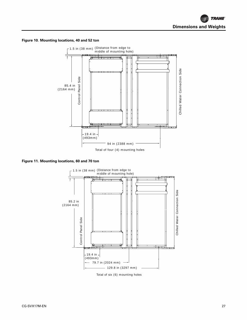
Weights
Base Units
Round Tube and Plate Fin Condenser Coils
Notes:
• Base unit weights include aluminum fins, refrigerant charge, elastomeric isolators, circuit breakers and louvers.
• For units with microchannel condenser coils, see “Microchannel Condenser Coils,” p. 34.
• These weights do NOT include the following options: partial heat recovery, copper fins or seismic isolators. See “Option Weights,” p. 36 for additional weight added by these option selections.
Table 12. Base unit weights, 60 Hz, round tube and plate fin condenser — I-P (lb)
Unit Size
(Tons)Base Unit
Base UnitWith Pump Package
Base UnitWith Pump Package and Buffer Tank
Shipping Operating Shipping Operating Shipping Operating
High Efficiency
20 2185 2208 2726 2814 3252 4491
26 2249 2278 2790 2891 3317 4562
30 2846 2880 3388 3497 3915 5163
35 2878 2920 3420 3546 3947 5204
40 3666 3697 4285 4383 4876 6116
52 3761 3806 4379 4506 4971 6225
60 4978 5033 5814 5986 6406 7695
70 5045 5121 5881 6094 6473 7782
80 5607 5692 6486 6790 7077 8561
90 5859 5961 6738 7075 7329 8830
100 6646 6759 7549 7909 8265 10136
110 6724 6846 7627 8005 8343 10223
120 6762 6884 8018 8396 8733 10614
130 7753 7900 9006 9430 9722 11623
Extra Efficiency
20 2258 2281 2798 2887 3325 4564
26 2322 2351 2863 2964 3389 4634
30 2945 2979 3487 3596 4014 5262
35 3023 3065 3565 3691 4092 5349
40 3812 3843 4431 4529 5022 6262
52 3959 4004 4578 4705 5169 6423
60 5177 5232 6013 6184 6604 7893
70 5118 5194 5954 6166 6545 7855
110 6724 6846 7627 8005 8343 10223
120 6762 6884 8018 8396 8733 10614
Note: All weights ±3%.
CG-SVX17M-EN 31

Dimensions and Weights
Table 13. Base unit weights, 60 Hz, round tube and plate fin condenser — SI (kg)
Unit Size
(Tons)Base Unit
Base UnitWith Pump Package
Base UnitWith Pump Package and Buffer Tank
Shipping Operating Shipping Operating Shipping Operating
High Efficiency
20 991 1002 1236 1277 1475 2037
26 1020 1034 1265 1311 1504 2069
30 1291 1306 1537 1586 1776 2342
35 1305 1325 1551 1608 1790 2360
40 1663 1677 1944 1988 2212 2774
52 1706 1726 1987 2044 2255 2824
60 2258 2283 2637 2715 2906 3490
70 2289 2323 2668 2764 2936 3530
80 2543 2582 2942 3080 3210 3883
90 2658 2704 3056 3209 3324 4005
100 3015 3066 3424 3587 3749 4598
110 3050 3105 3460 3631 3784 4637
120 3067 3122 3637 3808 3961 4814
130 3517 3583 4085 4277 4410 5272
Extra Efficiency
20 1024 1035 1269 1310 1508 2070
26 1053 1066 1298 1344 1537 2102
30 1336 1351 1582 1631 1821 2387
35 1371 1390 1617 1674 1856 2426
40 1729 1743 2010 2054 2278 2840
52 1796 1816 2077 2134 2345 2914
60 2348 2373 2727 2805 2996 3580
70 2322 2356 2701 2797 2969 3563
110 3050 3105 3460 3631 3784 4637
120 3067 3122 3637 3808 3961 4814
Note: All weights ±3%.
32 CG-SVX17M-EN

Dimensions and Weights
Table 14. Base unit weights, 50 Hz, round tube and plate fin condenser
Unit Size (Tons)
I-P Units (lb) SI Units (kg)
Shipping Operating Shipping Operating
High Efficiency
20 2187 2210 992 1002
26 2249 2278 1020 1034
30 2846 2880 1291 1306
35 2878 2920 1305 1325
40 3666 3697 1663 1677
52 3761 3806 1706 1726
60 4978 5033 2258 2283
70 5045 5121 2289 2323
80 5607 5692 2543 2582
90 5858 5960 2657 2703
100 6630 6743 3007 3059
110 6713 6835 3045 3100
120 6758 6880 3065 3121
Extra Efficiency
20 2260 2283 1025 1035
26 2322 2351 1053 1066
30 2945 2979 1336 1351
35 3023 3065 1371 1390
40 3812 3843 1729 1743
52 3959 4004 1796 1816
60 5177 5232 2348 2373
70 5118 5194 2322 2356
110 6713 6835 3045 3100
120 6758 6880 3065 3121
Note: All weights ±3%.
CG-SVX17M-EN 33

Dimensions and Weights
Microchannel Condenser Coils
Notes:
• Base unit weights include refrigerant charge, isolators, circuit breakers and louvers.
• For units with round tube and plate fin condensers, see “Round Tube and Plate Fin Condenser Coils,” p. 31.
Table 15. Base unit weights, 60 Hz, microchannel condenser — I-P (lb)
Unit Size
(Tons)
Base UnitBase Unit
With Pump PackageBase Unit
With Pump Package and Buffer Tank
Shipping Operating Shipping Operating Shipping Operating
High Efficiency
20 1967 1975 2507 2582 3034 4259
26 2030 2046 2571 2659 3098 4329
30 2388 2403 2929 3021 3456 4686
35 2608 2630 3150 3256 3677 4914
40 3307 3314 3926 3999 4517 5732
52 3402 3422 4021 4122 4612 5840
60 4136 4156 4972 5108 5563 6817
70 4579 4616 5415 5589 6006 7278
80 4888 4899 5766 5996 6357 7768
90 5141 5163 6020 6277 6611 8032
100 5816 5838 6719 6988 7434 9215
110 5893 5924 6796 7083 7511 9301
120 5930 5966 7186 7477 7902 9696
130 6722 6757 7976 8287 8691 10480
Note: All weights ±3%.
Table 16. Base unit weights, 60 Hz, microchannel condenser — SI (kg)
Unit Size
(Tons)
Base UnitBase Unit
With Pump PackageBase Unit
With Pump Package and Buffer Tank
Shipping Operating Shipping Operating Shipping Operating
High Efficiency
20 892 896 1137 1171 1376 1932
26 921 928 1166 1206 1405 1964
30 1083 1090 1329 1370 1568 2126
35 1183 1193 1429 1477 1668 2229
40 1500 1503 1781 1814 2049 2600
52 1543 1552 1824 1870 2092 2649
60 1876 1885 2255 2317 2523 3092
70 2077 2094 2456 2535 2724 3301
80 2217 2222 2616 2720 2884 3523
90 2332 2342 2731 2847 2999 3643
100 2638 2648 3048 3170 3372 4180
110 2673 2687 3083 3213 3407 4219
120 2690 2706 3260 3392 3584 4398
130 3049 3065 3618 3759 3942 4754
Note: All weights ±3%.
34 CG-SVX17M-EN

Dimensions and Weights
Table 17. Base unit weights, 50 Hz, microchannel condenser
Unit Size (Tons)
I-P (lb) SI (kg)
Shipping Operating Shipping Operating
High Efficiency
20 1967 1978 892 897
26 2030 2046 921 928
30 2388 2403 1083 1090
35 2608 2630 1183 1193
40 3307 3314 1500 1503
52 3402 3422 1543 1552
60 4136 4156 1876 1885
70 4579 4616 2077 2094
80 4888 4899 2217 2222
90 5139 5163 2331 2342
100 5798 5822 2630 2641
110 5882 5913 2668 2682
120 5926 5961 2688 2704
Note: All weights ±3%.
CG-SVX17M-EN 35

Dimensions and Weights
Option Weights
Note: Weights listed below are in addition to base unit weights found in previous section. For total unit weight, add option weights to base unit weight found in “Round Tube and Plate Fin Condenser Coils,” p. 31.
Table 18. Option weights, 60 Hz, round tube and plate fin condenser
Unit Size
(tons)
I-P Units (lb) SI Units (kg)
Partial Heat Recovery
Copper FinsSeismic Isolator
Partial Heat Recovery
Copper FinsSeismic Isolator Shipping Operating Shipping Operating
High Efficiency
20 39 63 258 160 18 28 117 73
26 39 70 258 160 18 32 117 73
30 47 82 359 160 21 37 163 73
35 47 91 359 160 21 41 163 73
40 94 128 516 160 43 58 234 73
52 94 143 516 160 43 65 234 73
60 111 170 719 240 50 77 326 109
70 111 191 719 240 50 87 326 109
80 170 260 1270 240 77 118 576 109
90 170 279 1270 240 77 126 576 109
100 178 298 1512 240 81 135 686 109
110 178 307 1512 240 81 139 686 109
120 178 310 1512 240 81 140 686 109
130 178 335 1889 320 81 152 857 145
Extra Efficiency
20 39 63 258 - 18 28 117 -
26 39 70 258 - 18 32 117 -
30 47 82 360 - 21 37 163 -
35 47 91 360 - 21 41 163 -
40 94 128 516 - 43 58 234 -
52 94 143 516 - 43 65 234 -
60 111 170 720 - 50 77 326 -
70 111 191 720 - 50 87 326 -
110 178 307 1512 - 81 139 686 -
120 178 310 1512 - 81 140 686 -
Note: All weights ±3%.
36 CG-SVX17M-EN

Dimensions and Weights
Table 19. Option weights, 50 Hz, round tube and plate fin condenser
Unit Size
(tons)
I-P Units (lb) SI Units (kg)
Partial Heat Recovery
Copper FinsSeismic Isolator
Partial Heat Recovery
Copper FinsSeismic Isolator Shipping Operating Shipping Operating
High Efficiency
20 40 24 258 160 18 11 117 73
26 40 31 258 160 18 14 117 73
30 46 35 359 160 21 16 163 73
35 46 44 359 160 21 20 163 73
40 95 33 516 160 43 15 234 73
52 95 49 516 160 43 20 234 73
60 110 60 719 240 50 27 326 109
70 110 79 719 240 50 36 326 109
80 170 90 1270 240 77 41 576 109
90 170 108 1270 240 77 49 576 109
100 179 119 1512 240 81 54 686 109
110 179 130 1512 240 81 59 686 109
120 179 130 1512 240 81 59 686 109
Extra Efficiency
20 40 24 258 - 18 11 117 -
26 40 31 258 - 18 14 117 -
30 46 35 359 - 21 16 163 -
35 46 44 359 - 21 20 163 -
40 95 33 516 - 43 15 234 -
52 95 49 516 - 43 22 234 -
60 110 60 719 - 50 27 326 -
70 110 79 719 - 50 36 326 -
110 179 130 1512 - 81 59 686 -
120 179 130 1512 - 81 59 686 -
Note: All weights ±3%.
CG-SVX17M-EN 37

Installation - Mechanical
Location Requirements
Sound Considerations
• Refer to Trane Engineering Bulletin Chiller Sound Ratings and Installation Guide CG-PRB010-EN for sound consideration applications.
• Locate the unit away from sound-sensitive areas.
• Install the optional elastomeric isolators under the unit. See “Unit Isolation and Leveling,” p. 45.
• Chilled water piping should not be supported by chiller frame.
• Install rubber vibration isolators in all water piping.
• Seal all wall penetrations.
Note: Consult an acoustical engineer for critical applications.
Wind Load Considerations
For units with wind load certification and architectural louvered panels (model number digit 17 = D), refer to Technical Evaluation Report listed below for necessary storm preparation.
Foundation
Provide rigid, non-warping mounting pads or a concrete foundation of sufficient strength and mass to support the applicable operating weight (i.e., including completed piping, and full operating charges of refrigerant, oil and water). Refer to the chapter on “Unit Dimensions/Weights” for unit operating weights. Once in place, the unit must be level within 1/4” (6.4 mm) over its length and width. The Trane Company is not responsible for equipment problems resulting from an improperly designed or constructed foundation.
Clearances
Provide enough space around the unit to allow the installation and maintenance personnel unrestricted access to all service points. Refer to submittal drawings for the unit dimensions, to provide sufficient clearance for the opening of control panel doors and unit service. See “Service Clearances,” p. 25 for minimum clearances. In all cases, local codes which require additional clearances will take precedence over these recommendations.
Rigging
See “Weights,” p. 31 for typical unit lifting weights. Refer to the rigging label attached to the unit for further details.
Lifting Procedure
Lifting using either a single spreader bar or an H-type spreader is acceptable. Attach chains or cables to lifting beam. Lifting beam crossbars MUST be positioned so lifting cables do not contact the sides of the unit.
Important: The center of gravity (CG) is never at the midpoint of the base rail lifting strap holes. A level unit lift is required for a safe lift and to prevent unit damage.
Lifting a unit with equal length straps will NOT produce a level unit during the lift because the CG will not be at the midpoint between the base lifting holes. The following adjustments must be made to produce a level lift:
• Single spreader bar lifting method
• If the unit CG is closer to the control panel, the straps on the control panel side of the spreader bar must be adjusted to be shorter than those on the opposite side of the spreader bar, allowing the spreader bar to move toward the control panel and over the unit CG. Several adjustments of the strap length may be required to produce a level unit during lift.
Unit Size (tons) TER
40 to 70 TER-15-2904V
80 to 130 TER-15-2904W
WARNING
Heavy Objects!
Failure to follow instructions below or properly lift unit could result in unit dropping and possibly crushing operator/technician which could result in death or serious injury, and equipment or property-only damage. Ensure that all the lifting equipment used is properly rated for the weight of the unit being lifted. Each of the cables (chains or slings), hooks, and shackles used to lift the unit must be capable of supporting the entire weight of the unit. Lifting cables (chains or slings) may not be of the same length. Adjust as necessary for even unit lift.
WARNING
Improper Unit Lift!
Failure to properly lift unit could result in unit dropping and possibly crushing operator/technician which could result in death or serious injury, and equipment or property-only damage. Test lift unit approximately 24 inches to verify proper center of gravity lift point. To avoid dropping of unit, reposition lifting point if unit is not level.
NOTICE:
Equipment Damage!
To prevent damage to unit, do not fork lift or allow lifting cables to contact unit during lift.
38 CG-SVX17M-EN

Installation - Mechanical
• H-type spreader bar lifting method
• If the straps from the H bar to the unit base are the same length, the crane lifting point on the center web of the H bar must be adjusted to produce a level unit lift. See Figure 17, p. 39 for illustration.
Figure 17. H-type spreader bar adjustment
for level unit lift
Figure 18. CGAM slant 20 to 35 ton unit rigging
Lifting Straps to unit base
Crane lift point
“H” type spreader bar
Crane lift point must move to the unit CG to produce a level unit lift
Figure 19. CGAM V 40 to 70 ton unit rigging
Figure 20. CGAM W 80 to 130 ton unit rigging
X Y
Z
X
Z
Y
CG-SVX17M-EN 39

Installation - Mechanical
Center of Gravity
Note: Center of gravity values do not change if wind load option is selected.
Units with Round Tube and Plate Fin (RTPF)
Condenser
Table 20. Center of gravity (in) — RTPF condenser, 60 Hz, high efficiency
Unit (tons)
Aluminum fins Copper fins
Base UnitWith Pump
PackageWith Pump Pkg,
Buffer Tank Base UnitWith Pump
PackageWith Pump Pkg,
Buffer TankX Y Z X Y Z X Y Z X Y Z X Y Z X Y Z
Units without Partial Heat Recovery
20 50 24 38 56 23 34 67 23 35 51 24 39 57 23 35 67 23 35
26 49 24 38 56 23 33 67 23 34 51 24 39 57 23 34 67 23 35
30 65 24 39 73 23 35 86 23 36 67 24 40 74 23 36 85 23 37
35 63 23 38 72 22 34 84 23 35 65 23 39 73 23 35 83 23 36
40 48 45 37 53 42 34 62 43 35 50 45 38 53 42 35 61 43 36
52 49 45 37 53 43 34 61 43 34 50 45 38 53 43 35 61 43 35
60 64 45 39 69 43 36 78 43 36 65 45 40 69 43 37 78 43 37
70 62 46 37 67 43 35 75 43 35 63 45 38 67 43 36 75 43 36
80 59 47 38 68 46 37 68 46 35 62 46 42 69 46 41 68 46 39
90 59 47 37 68 46 36 67 46 34 61 46 41 68 46 40 68 46 38
100 72 47 38 82 46 37 81 46 35 75 46 42 82 46 41 81 46 39
110 72 47 38 81 46 37 80 46 35 74 46 42 81 46 41 81 46 39
120 72 47 38 83 46 36 82 46 35 74 46 42 83 46 40 83 46 38
130 86 47 39 100 46 38 100 46 36 89 46 44 100 46 42 101 46 40
Units with Partial Heat Recovery
20 50 24 38 57 23 33 67 23 34 52 24 39 57 23 35 67 24 35
26 50 24 37 56 23 33 67 23 34 51 24 38 57 23 34 67 23 35
30 65 24 39 73 23 35 86 24 35 67 24 40 74 23 36 85 24 36
35 63 23 37 71 23 34 83 23 34 65 23 38 73 23 35 83 23 35
40 50 45 37 54 42 34 62 43 35 51 45 38 54 43 35 62 43 36
52 50 45 37 54 43 34 62 43 35 51 45 38 54 43 35 62 43 35
60 65 45 40 70 43 36 79 43 37 67 45 40 71 43 37 79 43 37
70 63 46 38 68 43 35 76 43 35 65 45 38 69 43 36 76 43 36
80 58 47 38 67 46 37 67 46 35 61 46 42 68 46 41 67 46 39
90 58 47 37 67 46 36 66 46 35 60 46 41 67 46 40 67 46 39
100 71 47 38 80 46 37 79 46 35 73 46 42 81 46 41 80 46 39
110 71 47 38 80 46 37 79 46 35 73 46 42 80 46 41 80 46 39
120 70 47 38 82 46 36 81 46 35 73 46 42 82 46 40 82 46 39
130 84 46 39 98 46 38 99 46 36 88 46 44 99 46 42 100 46 40
40 CG-SVX17M-EN

Installation - Mechanical
Table 21. Center of gravity (in) — RTPF condenser, 60 Hz, extra efficiency
Unit (tons)
Aluminum fins Copper fins
Base UnitWith Pump
PackageWith Pump Pkg,
Buffer Tank Base UnitWith Pump
PackageWith Pump Pkg,
Buffer TankX Y Z X Y Z X Y Z X Y Z X Y Z X Y Z
Units without Partial Heat Recovery
20 50 24 39 57 23 34 67 23 35 52 24 40 58 23 36 67 23 36
26 50 24 38 56 23 34 67 23 35 52 24 39 57 23 35 67 23 36
30 65 24 39 74 23 35 86 23 36 68 24 41 75 23 37 85 23 37
35 64 23 38 72 23 34 83 23 35 67 23 39 73 23 36 83 23 36
40 49 45 37 53 42 34 61 43 35 50 45 38 54 43 36 61 43 36
52 49 45 37 53 43 34 61 43 35 50 45 38 54 43 35 61 43 36
60 64 45 40 69 43 36 78 43 37 66 45 40 70 43 38 77 43 38
70 62 45 38 67 43 35 75 43 35 64 45 39 68 43 36 75 44 36
110 72 47 38 81 46 37 80 46 35 74 46 42 81 46 41 81 46 39
120 72 47 38 83 46 36 82 46 35 74 46 42 83 46 40 83 46 38
Units with Partial Heat Recovery
20 51 24 38 57 23 34 67 23 35 53 24 39 58 23 35 67 24 36
26 50 24 38 56 23 33 67 23 34 52 24 39 57 23 35 67 23 35
30 65 24 39 74 23 35 86 24 36 68 24 40 75 23 37 85 24 37
35 64 23 37 72 23 34 83 23 35 67 24 39 73 23 36 83 23 36
40 50 45 38 54 42 35 62 43 35 51 45 39 55 43 36 62 43 36
52 50 45 37 54 43 34 62 43 35 51 45 38 55 43 36 61 43 36
60 66 45 40 70 43 37 79 43 37 68 45 40 71 43 38 78 43 38
70 64 45 38 68 43 35 76 43 35 66 45 39 69 43 36 76 44 37
110 71 47 38 80 46 37 79 46 35 73 46 42 80 46 41 80 46 39
120 70 47 38 82 46 36 81 46 35 73 46 42 82 46 40 82 46 39
CG-SVX17M-EN 41

Installation - Mechanical
Table 22. Center of gravity (in) — RTPF condenser, 50 Hz, high efficiency
Unit (tons)
Aluminum fins Copper fins
Base UnitWith Pump
PackageWith Pump Pkg,
Buffer Tank Base UnitWith Pump
PackageWith Pump Pkg,
Buffer TankX Y Z X Y Z X Y Z X Y Z X Y Z X Y Z
Units without Partial Heat Recovery
20 49 24 38 54 23 35 66 23 35 51 24 39 55 23 36 66 23 36
26 49 24 38 54 23 34 66 23 35 51 24 39 55 23 35 66 23 36
30 65 24 39 71 23 36 84 23 36 67 24 40 72 23 37 84 24 37
35 63 23 38 69 23 35 82 23 35 65 23 39 71 23 36 82 23 36
40 48 45 37 52 43 35 61 43 35 50 45 38 52 43 36 60 43 36
52 49 45 37 52 43 34 61 43 35 50 45 38 53 43 35 60 43 36
60 64 45 39 69 43 36 78 43 36 65 45 40 70 43 37 78 43 37
70 62 46 37 67 43 34 76 43 35 63 45 38 68 43 35 76 43 36
80 59 47 38 68 46 37 67 46 35 62 46 42 69 46 41 68 46 39
90 59 47 37 67 46 36 67 46 35 61 46 41 68 46 40 67 46 38
100 72 47 38 81 46 37 80 46 35 74 46 42 81 46 41 80 46 39
110 72 47 38 81 46 37 80 46 35 74 46 42 81 46 41 80 46 39
120 72 47 38 82 46 36 81 46 35 74 46 42 82 46 40 81 46 39
Units with Partial Heat Recovery
20 49 24 38 54 23 34 66 24 35 51 24 39 55 23 35 66 24 36
26 50 24 37 54 23 34 66 23 35 51 24 38 55 23 35 66 24 36
30 65 24 39 71 23 36 84 24 36 67 24 40 72 24 37 84 24 37
35 63 23 37 69 23 34 82 23 35 65 23 38 71 23 35 82 23 36
40 50 45 37 53 43 35 62 43 35 51 45 38 53 43 36 61 43 36
52 50 45 37 53 43 35 62 43 35 51 45 38 54 43 35 61 43 36
60 65 45 40 71 43 36 80 43 36 67 45 40 71 43 37 79 43 37
70 63 46 38 69 43 35 77 43 35 65 45 38 69 43 35 77 43 36
80 58 47 38 67 46 37 66 46 35 61 46 42 68 46 41 67 46 39
90 58 47 37 66 46 36 66 46 35 60 46 41 67 46 40 67 46 39
100 70 47 38 79 46 37 79 46 36 73 46 42 80 46 41 79 46 39
110 70 47 38 79 46 37 79 46 35 73 46 42 80 46 41 79 46 39
120 70 47 38 80 46 37 80 46 35 73 46 42 81 46 40 80 46 39
42 CG-SVX17M-EN

Installation - Mechanical
Table 23. Center of gravity (in) — RTPF condenser, 50 Hz, extra efficiency
Unit (tons)
Aluminum fins Copper fins
Base UnitWith Pump
PackageWith Pump Pkg,
Buffer Tank Base UnitWith Pump
PackageWith Pump Pkg,
Buffer TankX Y Z X Y Z X Y Z X Y Z X Y Z X Y Z
Units without Partial Heat Recovery
20 50 24 39 57 23 34 67 23 35 52 24 40 58 23 36 67 23 36
26 50 24 38 56 23 34 67 23 35 52 24 39 57 23 35 67 23 36
30 65 24 39 74 23 35 86 23 36 68 24 41 75 23 37 85 23 37
35 64 23 38 72 23 34 83 23 35 67 23 39 73 23 36 83 23 36
40 49 45 37 53 42 34 61 43 35 50 45 38 54 43 36 61 43 36
52 49 45 37 53 43 34 61 43 35 50 45 38 54 43 35 61 43 36
60 64 45 40 69 43 36 78 43 37 66 45 40 70 43 38 77 43 38
70 62 45 38 67 43 35 75 43 35 64 45 39 68 43 36 75 44 36
110 72 47 38 81 46 37 80 46 35 74 46 42 81 46 41 80 46 39
120 72 47 38 82 46 36 81 46 35 74 46 42 82 46 40 81 46 39
Units with Partial Heat Recovery
20 51 24 38 57 23 34 67 23 35 53 24 39 58 23 35 67 24 36
26 50 24 38 56 23 33 67 23 34 52 24 39 57 23 35 67 23 35
30 65 24 39 74 23 35 86 24 36 68 24 40 75 23 37 85 24 37
35 64 23 37 72 23 34 83 23 35 67 24 39 73 23 36 83 23 36
40 50 45 38 54 42 35 62 43 35 51 45 39 55 43 36 62 43 36
52 50 45 37 54 43 34 62 43 35 51 45 38 55 43 36 61 43 36
60 66 45 40 70 43 37 79 43 37 68 45 40 71 43 38 78 43 38
70 64 45 38 68 43 35 76 43 35 66 45 39 69 43 36 76 44 37
110 70 47 38 79 46 37 79 46 35 73 46 42 80 46 41 79 46 39
120 70 47 38 80 46 37 80 46 35 73 46 42 81 46 40 80 46 39
CG-SVX17M-EN 43

Installation - Mechanical
Units with Microchannel Condenser
Table 24. Center of gravity (in) — microchannel condenser, high efficiency
Unit (tons)
60 Hz Units 50 Hz UnitsBase Unit With Pump Package With Pump Pkg, Buffer Tank Base Unit
X Y Z X Y Z X Y Z X Y ZHigh Efficiency Units
20 49 38 24 56 33 23 68 34 23 49 38 24
26 49 37 24 56 33 23 67 34 23 49 37 24
30 64 39 24 73 34 23 86 35 23 64 39 24
35 62 37 23 71 33 22 84 34 23 62 37 23
40 47 37 45 52 33 42 62 34 42 47 37 45
52 48 36 45 52 33 43 62 34 43 48 36 45
60 62 39 45 68 35 43 78 36 43 62 39 45
70 60 37 46 66 34 43 75 34 43 60 37 46
80 58 35 47 68 34 47 67 32 46 58 35 47
90 58 34 47 67 33 47 67 32 47 58 34 47
100 71 35 47 82 34 47 81 33 47 71 35 47
110 71 35 47 81 34 47 80 33 47 71 35 47
120 70 35 47 84 33 47 83 32 47 70 35 47
130 84 36 47 99 35 46 100 33 46 - - -
44 CG-SVX17M-EN

Installation - Mechanical
Unit Isolation and Leveling
General
Construct an isolated concrete pad for the unit or provide concrete footings at each of the unit mounting points. Mount the unit directly to the concrete pads or footings.
Level the unit using the base rail as a reference. The unit must be level within 1/4” over the entire length (end-to-end as well as side-to-side). Use shims as necessary to level the unit.
Isolator Options
Elastomeric Isolators
Install the optional neoprene isolators at each mounting location. Isolators are identified by part number and color.
1. Secure the isolators to the mounting surface, using the mounting slots in the isolator base plate, as shown in Figure 21. Do not fully tighten the isolator mounting bolts at this time.
2. Align the mounting holes in the base of the unit, with the threaded positioning pins on the top of isolators.
3. Lower the unit on to the isolators and secure the isolator to the unit with a nut. Level the unit carefully. Refer to “Leveling”. Fully tighten the isolator mounting bolts.
Seismically Rated Isolators
Seismically rated isolators are required for OSHPD and IBC seismically rated units.
Seismic Isolator Specifications
Isolators are identified by part number and color. See Table 26. For dimensions, see Figure 22 and Figure 23, p. 46. Install the optional seismically rated isolators at each mounting location.
Figure 21. CGAM elastomeric isolator
HH
A
E
L
C
W
D Dia 2 Holes
B NC TAP
HH
E
A
DW
CL
« B » DiaRP/RDP« M »
Mounting molded in Neoprene
1/2-13
Mounting molded in Neoprene
1/2-13NC-2B
Table 25. CGAM elastomeric rated isolator
ExtMax Load
(lbs) ColorMaximum
Deflection (in) Type
57 250 Black
0.50 RDP3-WR58 525 Red
59 750 Green
60 1100 Gray
61 1500 Brown
0.50 RDP4-WR62 2250 Red
63 3000 Green
64 4000 Gray
Ext A B C D E H L M W
57
2.5 .5 4.12 .56 .25 2.88 5.5 1.13 3.3858
59
60
61
3.0 .5 5.0 .56 .38 2.75 6.25 1.60±.25 4.63
62
63
64
Table 26. CGAM seismically rated isolator
Model
Rated Load (lbs)
Rated Deflection (in)
Spring Rate (lbs/in) Color Code
MSSH-1E-530N 530 1.17 453 Black/Dk Blue
MSSH-1E-825N 825 1.07 769 Red/ Dk Blue
MSSH-1E-1000 1000 1.00 1000 Tan
M2SS-1E-800 800 1.32 606 Black
M2SS-1E-1060N 1060 1.17 906 Black/Dk Blue
M2SS-1E-1300 1300 1.05 1240 Red
M2SS-1E-1650N 1650 1.07 1538 Red/Dk Blue
M2SS-1E-2000 2000 1.00 2000 Tan
M2SS-1E-2400N 2400 1.04 2300 Tan/Dk Blue
CG-SVX17M-EN 45

Installation - Mechanical
ITY
Figure 22. MSSH seismically rated isolator
8FREE &
OPERATINGHEIGHT
10 1/4
1/4 - 3/8
ELASTOMERICSNUBBER
3/8 GAP
5/8 ADJUSTINGNUT
STEEL SHIM(REMOVE AFTERSPRING ADJUSTMENT)
ELASTOMERICCUP
TOPCOMPRESSIONCUP
PVCBUSHING
(BASE PLATE)3/4 DIA HOLE FORATTACHMENT TOSTEEL (4 TYP)(VIEW CUT AWAY FOR CLAR
13/16 DIA HOLE FORATTACHMENT TOCONCRETE (4 TYP)
2 7/8
2 1/4
7/8
6 1/4
1 1/88
7 1/41 1/2
CUSTOMEREQUIPMENT
1/2 LIMIT STOP(NOT SHOWNIN TOP VIEWFOR CLARITY)
8
(3/8)
(1/2)
5 3/4
SHIPPING SPACERREMOVAL STRAP(NOT SHOWNIN OTHER VIEWFOR CLARITY)
CUSTOMEREQUIPMENT
5/8 EQUIPMENTCLAMP DOWN NUT
Figure 23. M2SS seismically rated isolator
3/8 GAP
7 1/4FREE &
OPERATINGHEIGHT
(BASE PLATE)3/4 DIA HOLE FORATTACHMENT TOSTEEL (4 TYP)(VIEW CUT AWAY FOR CLAR
13/16 DIA HOLE FORATTACHMENT TOCONCRETE (4 TYP)
5/8 ADJUSTING NUT(2 TYP)
STEEL SHIM(REMOVE AFTERSPRING ADJUSTMENT)
ELASTOMERICSNUBBER
ELASTOMERICCUP
2 7/8
2 1/4
7/8
6 1/4
1 1/2 11 1/4
14 1/4
2
1/4 - 3/8
7 1/8
5/8 EQUIPMENTCLAMP DOWN NUT
CUSTOMEREQUIPMENT
PVCBUSHING
1/2 LIMIT STOP(NOT SHOWNIN TOP VIEW
FOR CLARITY)
8
(3/8)
(1/2)
4 3/4CUSTOMEREQUIPMENT
TOPCOMPRESSION CUP(2 TYP)
46 CG-SVX17M-EN

Installation - Mechanical
Installation of Seismically Rated Isolators
See Figure 24 and Figure 25, p. 47 for reference.
1. Set isolators on mounting surface, ensuring that all isolator centerlines match the submittal drawing. All
isolator base plates (B) must be installed on a level surface. Shim or grout as required, leveling all isolat(or base plates at the same elevation.
2. Anchor all isolators to the surface using thru holes (C) for concrete or (D) for steel as require. Welding to steel is permitted providing the weld achieves the required strength.
3. Remove clamp down nut (H) and washer (I). Isolators are shipped with (2) removable spacer shims (E) between the top plate and the housing.
Important: These shims MUST be in place when the equipment is positioned over the isolators.
4. With all shims (E) in place, place the equipment onto the top plate (A) of the isolators.
5. Bolt equipment securely to the isolators using doubler plate (included in isolator kit), washer (I) and nut (H) as shown in Figure 26, p. 47.
Important: The following adjustment process can only begin after the equipment or machine is at its full operating weight.
6. Back off each of the (2) or (4) limit stop locknuts (F) per isolator 1/4-3/8”.
7. Adjust each isolator in sequence by turning adjusting nut(s) (G) one full clockwise turn at a time. Repeat this procedure on all isolators, one at a time. check the limit stop locknuts (F) periodically to ensure that clearance between the washer and rubber grommet is maintained. Stop adjustment of an isolator only when the top plate (A) has risen just above the shim (E).
8. Remove all spacer shims (E).
9. Fine adjust isolators to level equipment.
10. Adjust all limit stop locknuts (F) per isolator to obtain 3/8” gap. the limit stop nuts must be kept at this 3/8” gap to ensure uniform bolt loading during uplift.
Elastomeric Pads
Elastomeric pads are required for units with wind load rating option (model number digit 17 = D).
Figure 24. MSSH seismic isolator installation reference
Figure 25. M2SS seismic isolator installation reference
("A")("E") ("G") ("E")
GROMMET
WASHER
("F")
("B")
1/4 - 3/8
("H")CUSTOMEREQUIPMENT
("I")
("C") ("D") ("C")
("F")
("E")("A")
CUSTOMEREQUIPMENT
("I")("H")
("A")
("E") ("E")("G")
GROMMET
WASHER
("F")
("B")
1/4 - 3/8
CUSTOMEREQUIPMENT
("G")
("H")("I")
("C") ("D") ("C")
("F")
("A")
("E")
CUSTOMEREQUIPMENT
("H")("I")
Figure 26. Seismic isolator installation detail
DoublerPlateG rail
Isolator(top
panel)
Screw
Nut
Washer
CG-SVX17M-EN 47

Installation - Mechanical
See “Units with Wind Load Option,” p. 64 for information on quantities required and mounting point identification.
Elastomeric pads ship inside the unit control panel. They are provided with an isolation washer and 3/4” free hole in the center of the plate.
Isolator Selection and Placement
Units without Wind Load Option
Notes:
• Information in this section is applicable to units with elastomeric or seismic isolator options.
• For units with wind load rating option (model number digit model number digit 17 = D), see “Units with Wind Load Option,” p. 64.
• See “Mounting Locations,” p. 26 for mounting point locations dimensions.
Figure 27. Isolation pad — installed
Table 27. Seismically rated elastomeric isolation pad
Dimension (in)
Model Max Load Length Width Height
B-36 2520 6 6 .625
Grade 8 WasherFender Washer
IsolationWasher
Unit Base Rail
Steel Plate
Isolation Pad
Grade 8 Bolt
Building Support Structure
Grade 8 WasherFender Washer
(Washers under support structure recommended if job site has an I-beam or C-channel.)
Nut
Figure 28. Mounting point identification,
units without wind load option
Con
trol
Pan
el
1
2
3
4
Con
trol
Pan
el
1
2
3
4
5
6
Con
trol
Pan
el
5
6
7
8
1
2
3
4
48 CG-SVX17M-EN

Installation - Mechanical
Isolator Selection
Non-Seismic Units
Seismic Units
Table 28. Elastomeric isolator selections — base unit (with or without partial heat recovery)
Unit Size (tons)
Location1 2 3 4 5 6 7 8
20, 26 RDP-3Grey 60
RDP-3Grey 60
RDP-3Grey 60
RDP-3 Grey 60
- - - -
30, 35 RDP-4 Brown 61
RDP-4 Brown 61
RDP-3 Grey 60
RDP-3 Grey 60
- - - -
40, 52 RDP-4 Red 62
RDP-4Red 62
RDP-4Red 62
RDP-4Red 62
- - - -
60, 70 RDP-4 Red 62
RDP-4 Red 62
RDP-3 Gray 60
RDP-4Brown 61
RDP-3 Gray 60
RDP-3 Gray 60
- -
80 to 90 RDP-4 Red 62
RDP-4 Green 63
RDP-4 Red 62
RDP-4 Red 62
RDP-3 Gray 60
RDP-3 Gray 60
- -
100 to 120RDP-4 Red 62
RDP-4 Green 63
RDP-4 Red 62
RDP-4 Red 62
RDP-3 Gray 60
RDP-3 Gray 60
- -
130 RDP-4 Red 62
RDP-4 Red 62
RDP-4 Red 62
RDP-4 Red 62
RDP-4 Brown 61
RDP-4 Brown 61
RDP-3Grey 60
RDP-3Grey 60
Table 29. Elastomeric isolator selections — with pump package (with or without partial heat recovery)
Unit Size (tons)
Location1 2 3 4 5 6 7 8
20, 26RDP-4Brown 61
RDP-3Grey 60
RDP-3Grey 60
RDP-3 Grey 60
- - - -
30, 35 RDP-4 Brown 61
RDP-4 Brown 61
RDP-4 Brown 61
RDP-4 Brown 61
- - - -
40, 52 RDP-4 Red 62
RDP-4Red 62
RDP-4Red 62
RDP-4Red 62
- - - -
60, 70RDP-4 Red 62
RDP-4 Red 62
RDP-4 Red 62
RDP-4 Red 62
RDP-4 Red 62
RDP-4 Red 62
- -
80 to 90 RDP-4 Red 62
RDP-4 Red 62
RDP-4 Red 62
RDP-4 Red 62
RDP-3Grey 60
RDP-3 Grey 60
- -
100 to 120 RDP-4 Green 63
RDP-4 Green 63
RDP-4 Green 63
RDP-4 Green 63
RDP-4 Red 62
RDP-4 Red 62
- -
130 RDP-4 Red 62
RDP-4 Red 62
RDP-4 Red 62
RDP-4 Red 62
RDP-4 Red 62
RDP-4 Red 62
RDP-4 Red 62
RDP-4 Red 62
Table 30. Elastomeric isolator selections — with pump package and buffer tank option (with or without partial heat recovery)
Unit Size (tons)
Location1 2 3 4 5 6 7 8
20, 26 RDP-3Grey 60
RDP-3Grey 60
RDP-4 Green 63
RDP-4 Green 63
- - - -
30, 35 RDP-3Grey 60
RDP-3Grey 60
RDP-4 Green 63
RDP-4 Green 63
- - - -
40, 52 RDP-4 Brown 61
RDP-4 Brown 61
RDP-4Grey 64
RDP-4Grey 64
- - - -
60, 70 RDP-4 Brown 61
RDP-4 Brown 61
RDP-4 Green 63
RDP-4 Green 63
RDP-4 Green 63
RDP-4 Green 63
- -
80 to 90 RDP-4 Green 63
RDP-4 Green 63
RDP-4 Red 62
RDP-4 Red 62
RDP-4 Brown 61
RDP-4 Brown 61
- -
100 to 120 RDP-4Grey 64
RDP-4Grey 64
RDP-4 Green 63
RDP-4 Green 63
RDP-4 Red 62
RDP-4 Red 62
- -
130 RDP-4 Green 63
RDP-4 Green 63
RDP-4 Green 63
RDP-4 Green 63
RDP-4 Green 63
RDP-4 Green 63
RDP-4 Green 63
RDP-4 Green 63
CG-SVX17M-EN 49

Installation - Mechanical
Table 31. Seismically rated isolator locations
Unit Size (ton)
Locations
1 2 3 4 5 6 7 8
20 MSSH-1E-825N Red/Dk Blue
MSSH-1E-825N Red/Dk Blue
MSSH-1E-530N Black/Dk Blue
MSSH-1E-530N Black/Dk Blue - - - -
26 MSSH-1E-1000 Tan
MSSH-1E-825N Red/Dk Blue
MSSH-1E-530N Black/Dk Blue
MSSH-1E-530N Black/Dk Blue - - - -
30 M2SS-1E-1300 Red
M2SS-1E-1060NBlack/Dk Blue
M2SS-1E-800 Black
M2SS-1E-800 Black - - - -
35 M2SS-1E-1300 Red
M2SS-1E-1060NBlack/Dk Blue
M2SS-1E-800 Black
M2SS-1E-800 Black - - - -
40 M2SS-1E-1300 Red
M2SS-1E-1300 Red
M2SS-1E-800 Black
M2SS-1E-1060NBlack/Dk Blue - - - -
52 M2SS-1E-1300 Red
M2SS-1E-1650NRed/Dk Blue
M2SS-1E-1060N Black/Dk Blue
M2SS-1E-1060N Black/Dk Blue - - - -
60M2SS-1E-
1650N Red/Dk Blue
M2SS-1E-1650NRed/Dk Blue
M2SS-1E-1060N Black/Dk Blue
M2SS-1E-1060N Black/Dk Blue
M2SS-1E-800 Black
M2SS-1E-800 Black - -
70M2SS-1E-
1650N Red/Dk Blue
M2SS-1E-1650N Red/Dk Blue
M2SS-1E-1060N Black/Dk Blue
M2SS-1E-1060N Black/Dk Blue
M2SS-1E-800 Black
M2SS-1E-800 Black - -
80 M2SS-1E-2000 Tan
M2SS-1E-2000 Tan
M2SS-1E-1060NBlack/Dk Blue
M2SS-1E-1300 Red
M2SS-1E-800 Black
M2SS-1E-800 Black - -
90 M2SS-1E-2000 Tan
M2SS-1E-2000 Tan
M2SS-1E-1060N Black/Dk Blue
M2SS-1E-1650N Red/Dk Blue
M2SS-1E-800 Black
M2SS-1E-800 Black - -
100 M2SS-1E-2000 Tan
M2SS-1E-2000 Tan
M2SS-1E-1300 Red
M2SS-1E-1650N Red/Dk Blue
M2SS-1E-800 Black
M2SS-1E-800 Black - -
110 M2SS-1E-2000 Tan
M2SS-1E-2000 Tan
M2SS-1E-1300 Red
M2SS-1E-1650N Red/Dk Blue
M2SS-1E-800 Black
M2SS-1E-800 Black - -
120 M2SS-1E-2000 Tan
M2SS-1E-2000 Tan
M2SS-1E-1300 Red
M2SS-1E-2000 Tan
M2SS-1E-800 Black
M2SS-1E-800 Black - -
130M2SS-1E-
1650N Red/Dk Blue
M2SS-1E-1650N Red/Dk Blue
M2SS-1E-1300 Red
M2SS-1E-1650N Red/Dk Blue
M2SS-1E-1060NBlack/Dk Blue
M2SS-1E-1300 Red
M2SS-1E-800 Black
M2SS-1E-1060NBlack/Dk Blue
50 CG-SVX17M-EN

Installation - Mechanical
Mounting Point Weights
Units with Round Tube, Plate Fin (RTPF) Condensers
Table 32. Point weights (lbs) — RTPF condensers, 60 Hz, high efficiency— base unit
Unit Size (tons)
Isolator location
Aluminum Fins Copper Fins
1 2 3 4 5 6 7 8 1 2 3 4 5 6 7 8
High Efficiency Units without Partial Heat Recovery
20 706 645 408 365 - - - - 822 648 425 487 - - - -
26 792 614 369 420 - - - - 807 716 486 442 - - - -
30 775 805 595 431 - - - - 916 828 641 581 - - - -
35 894 861 645 436 - - - - 1035 884 690 587 - - - -
40 1151 1036 611 811 - - - - 1198 1246 823 858 - - - -
52 1080 1155 714 768 - - - - 1209 1283 843 898 - - - -
60 972 1104 630 762 602 492 - - 1100 1167 855 904 610 644 - -
70 1117 1210 781 849 511 557 - - 1239 1330 910 977 622 668 - -
80 1435 1662 774 885 396 449 - - 1795 1834 863 1203 581 594 - -
90 1507 1763 802 927 406 466 - - 1872 1930 887 1249 591 610 - -
100 1640 1587 847 1120 608 866 - - 1770 1992 1194 1342 886 994 - -
110 1673 1634 850 1134 602 863 - - 1803 2038 1200 1356 878 993 - -
120 1690 1651 853 1138 600 861 - - 1820 2055 1204 1360 875 990 - -
130 1284 1272 910 1229 861 852 569 826 1269 1749 1301 1197 989 1246 1008 932
High Efficiency Units with Partial Heat Recovery
20 707 660 414 382 - - - - 773 713 482 453 - - - -
26 793 629 375 437 - - - - 752 789 550 402 - - - -
30 836 773 545 502 - - - - 921 852 645 597 - - - -
35 955 829 593 507 - - - - 1041 908 694 603 - - - -
40 1062 1111 749 785 - - - - 1191 1239 879 914 - - - -
52 1073 1148 770 825 - - - - 1202 1275 900 954 - - - -
60 931 988 827 884 504 543 - - 1170 1119 863 825 591 829 - -
70 1097 1190 812 880 558 604 - - 1311 1280 917 895 600 858 - -
80 1528 1756 780 891 384 437 - - 1888 1926 871 1213 568 580 - -
90 1602 1858 807 932 394 454 - - 1966 2023 896 1260 577 596 - -
100 1732 1680 860 1138 596 848 - - 1861 2083 1213 1361 869 978 - -
110 1765 1726 864 1152 589 845 - - 1934 1895 1209 1774 829 810 - -
120 1783 1744 867 1156 587 843 - - 1953 1912 1214 1780 827 807 - -
130 1129 1587 1144 1072 855 803 589 812 1589 1475 1145 1605 938 1203 990 934
CG-SVX17M-EN 51

Installation - Mechanical
Table 33. Point weights (lbs) — RTPF condensers, 60 Hz, extra efficiency— base unit
Unit Size (tons)
Isolator location
Aluminum Fins Copper Fins
1 2 3 4 5 6 7 8 1 2 3 4 5 6 7 8
Units without Partial Heat Recovery
20 724 663 426 383 - - - - 872 698 476 537 - - - -
26 810 632 387 439 - - - - 858 766 536 493 - - - -
30 800 830 620 456 - - - - 986 898 711 651 - - - -
35 919 886 669 460 - - - - 1105 954 760 657 - - - -
40 1188 1073 647 848 - - - - 1298 1346 923 958 - - - -
52 1117 1192 750 805 - - - - 1310 1383 944 998 - - - -
60 1005 1137 663 795 635 525 - - 1193 1261 948 998 704 737 - -
70 1150 1243 814 882 544 591 - - 1332 1423 1004 1071 715 761 - -
110 1673 1634 850 1134 602 863 - - 1803 2038 1200 1356 878 993 - -
120 1690 1651 853 1138 600 861 - - 1820 2055 1204 1360 875 990 - -
Units with Partial Heat Recovery
20 726 679 433 400 - - - - 823 763 532 504 - - - -
26 811 648 393 456 - - - - 802 839 600 453 - - - -
30 861 798 569 527 - - - - 991 922 715 667 - - - -
35 980 854 618 532 - - - - 1111 978 764 673 - - - -
40 1098 1147 785 821 - - - - 1291 1339 979 1014 - - - -
52 1110 1184 806 861 - - - - 1302 1376 1000 1054 - - - -
60 965 1022 860 917 537 576 - - 1263 1212 956 919 684 923 - -
70 1131 1223 845 913 591 637 - - 1404 1373 1011 988 694 951 - -
110 1765 1726 864 1152 589 845 - - 1934 1895 1209 1774 829 810 - -
120 1783 1744 867 1156 587 843 - - 1953 1912 1214 1780 827 807 - -
52 CG-SVX17M-EN

Installation - Mechanical
Table 34. Point weights (lbs) — RTPF condensers, 60 Hz, high efficiency — with pump package (no buffer tank)
Size (tons)
Isolator location
Aluminum Fins Copper Fins
1 2 3 4 5 6 7 8 1 2 3 4 5 6 7 8
Units without Partial Heat Recovery
20 874 612 603 618 - - - - 802 802 809 552 - - - -
26 910 630 614 624 - - - - 834 824 823 554 - - - -
30 832 836 904 619 - - - - 989 842 933 787 - - - -
35 946 896 958 619 - - - - 1182 824 908 865 - - - -
40 1214 1109 1009 932 - - - - 1336 1244 1146 1054 - - - -
52 1225 1146 1030 972 - - - - 1349 1279 1165 1095 - - - -
60 1204 943 802 862 734 794 - - 1250 1192 923 880 928 885 - -
70 1261 1226 866 840 818 792 - - 1290 1258 1196 1163 819 795 - -
80 1296 1663 922 1070 901 763 - - 1637 1812 1190 1306 927 1012 - -
90 1556 1616 816 1152 857 886 - - 1712 1910 1217 1349 934 1031 - -
100 1278 1684 1330 1175 1013 1226 - - 1561 1736 1653 1827 1162 1278 - -
110 1305 1733 1339 1189 1006 1221 - - 1593 1778 1661 1846 1151 1275 - -
120 1276 1623 1280 1629 1284 1091 - - 1742 1721 1721 1699 1133 1678 - -
130 835 1195 1150 1206 1167 1223 1177 1233 1341 1335 1253 1247 1116 1664 1564 1555
Units with Partial Heat Recovery
20 877 626 609 636 - - - - 802 819 816 568 - - - -
26 851 706 680 581 - - - - 835 841 830 570 - - - -
30 837 859 909 635 - - - - 996 864 936 804 - - - -
35 1025 846 889 709 - - - - 1189 846 910 884 - - - -
40 1118 1190 1154 899 - - - - 1328 1236 1202 1110 - - - -
52 1127 1229 1177 937 - - - - 1341 1271 1222 1152 - - - -
60 1186 928 824 883 786 845 - - 1234 1175 945 903 979 936 - -
70 1245 1209 889 863 869 843 - - 1272 1239 1224 1191 868 844 - -
80 1569 1609 804 1123 832 851 - - 1727 1902 1203 1320 910 996 - -
90 1648 1707 826 1166 842 870 - - 1803 2001 1230 1362 918 1015 - -
100 1584 1635 1178 1212 951 1331 - - 1648 1822 1680 1854 1141 1257 - -
110 1616 1680 1183 1226 943 1329 - - 1680 1865 1688 1873 1131 1254 - -
120 1586 1561 1136 1679 1212 1196 - - 1827 1809 1748 1730 1114 1653 - -
130 1066 1198 1089 1221 1124 1256 1143 1275 1381 1114 1358 1638 1323 1585 1305 1557
CG-SVX17M-EN 53

Installation - Mechanical
Table 35. Point weights (lbs) — RTPF condensers, 60 Hz, extra efficiency — with pump package (no buffer tank)
Size (tons)
Isolator location
Aluminum Fins Copper Fins
1 2 3 4 5 6 7 8 1 2 3 4 5 6 7 8
Units without Partial Heat Recovery
20 893 630 621 637 - - - - 852 853 859 602 - - - -
26 928 649 632 642 - - - - 884 875 873 605 - - - -
30 856 860 929 644 - - - - 1059 912 1003 857 - - - -
35 971 921 983 644 - - - - 1252 894 978 935 - - - -
40 1250 1145 1046 969 - - - - 1436 1344 1246 1155 - - - -
52 1262 1182 1066 1008 - - - - 1449 1379 1265 1196 - - - -
60 1237 976 835 895 767 827 - - 1343 1285 1016 974 1021 979 - -
70 1294 1259 899 874 851 825 - - 1384 1351 1289 1257 913 889 - -
110 1305 1733 1339 1189 1006 1221 - - 1593 1778 1661 1846 1151 1275 - -
120 1276 1623 1280 1629 1284 1091 - - 1742 1721 1721 1699 1133 1678 - -
Units with Partial Heat Recovery
20 895 644 627 655 - - - - 852 869 867 618 - - - -
26 870 724 699 599 - - - - 885 891 881 621 - - - -
30 862 884 934 660 - - - - 1066 934 1006 874 - - - -
35 1050 871 913 734 - - - - 1259 916 980 954 - - - -
40 1154 1227 1190 936 - - - - 1429 1337 1302 1210 - - - -
52 1164 1265 1213 974 - - - - 1442 1372 1322 1252 - - - -
60 1219 962 857 916 819 878 - - 1327 1269 1039 996 1072 1030 - -
70 1278 1242 922 896 902 876 - - 1365 1332 1317 1284 961 937 - -
110 1616 1680 1183 1226 943 1329 - - 1680 1865 1688 1873 1131 1254 - -
120 1586 1561 1136 1679 1212 1196 - - 1827 1809 1748 1730 1114 1653 - -
54 CG-SVX17M-EN

Installation - Mechanical
Table 36. Point weights (lbs) — RTPF condensers, 60 Hz, high efficiency — with pump package and buffer tank
Size (tons)
Isolator location
Aluminum Fins Copper Fins
1 2 3 4 5 6 7 8 1 2 3 4 5 6 7 8
Units without Partial Heat Recovery
20 616 413 1728 1650 - - - - 610 538 1867 1650 - - - -
26 650 434 1741 1653 - - - - 640 562 1883 1650 - - - -
30 663 585 1939 1703 - - - - 848 564 1940 1898 - - - -
35 868 555 1902 1793 - - - - 865 722 2092 1800 - - - -
40 838 790 2265 2135 - - - - 966 918 2395 2264 - - - -
52 856 820 2279 2181 - - - - 985 948 2409 2310 - - - -
60 679 656 1237 1191 1704 1636 - - 867 835 1224 1181 1889 1825 - -
70 875 857 1184 1159 1765 1726 - - 1001 981 1304 1278 1881 1841 - -
80 1868 2086 1234 1379 898 1005 - - 1892 2452 1703 1649 1040 1005 - -
90 1873 2145 1281 1657 957 828 - - 2169 2399 1565 1738 1012 1127 - -
100 1681 2251 1788 1796 1262 1267 - - 2291 2524 1638 1812 1559 1733 - -
110 1710 2298 1797 1810 1254 1263 - - 2324 2568 1645 1828 1549 1732 - -
120 1861 2235 1856 1671 1234 1666 - - 2313 2561 1709 1895 1684 1870 - -
130 1209 1222 1148 1741 1579 1599 1504 1523 1110 1688 1706 1728 1768 1790 1801 1824
Units with Partial Heat Recovery
20 623 423 1729 1672 - - - - 616 549 1870 1670 - - - -
26 585 516 1813 1604 - - - - 646 574 1886 1671 - - - -
30 674 603 1938 1724 - - - - 860 581 1938 1920 - - - -
35 880 572 1900 1816 - - - - 874 742 2092 1821 - - - -
40 830 783 2321 2191 - - - - 959 911 2451 2320 - - - -
52 849 813 2336 2238 - - - - 977 941 2466 2367 - - - -
60 668 645 1248 1202 1762 1693 - - 855 824 1238 1194 1945 1881 - -
70 864 845 1198 1172 1821 1783 - - 989 969 1317 1291 1938 1898 - -
80 1823 2357 1284 1248 980 953 - - 2217 2292 1679 1736 827 1165 - -
90 1959 2242 1296 1666 944 809 - - 2292 2389 1709 1781 832 1183 - -
100 1762 2347 1816 1814 1246 1245 - - 2380 2612 1661 1835 1540 1714 - -
110 1791 2394 1825 1829 1238 1241 - - 2412 2656 1668 1851 1530 1713 - -
120 1941 2333 1885 1694 1220 1639 - - 2403 2651 1733 1919 1665 1851 - -
130 1157 1611 1132 1573 1638 1513 1607 1482 1476 1637 1559 1720 1688 1849 1756 1918
CG-SVX17M-EN 55

Installation - Mechanical
Table 37. Point weights (lbs) — RTPF condensers, 60 Hz, extra efficiency — with pump package and buffer tank
Size (tons)
Isolator location
Aluminum Fins Copper Fins
1 2 3 4 5 6 7 8 1 2 3 4 5 6 7 8
Units without Partial Heat Recovery
20 635 432 1746 1668 - - - - 660 588 1917 1700 - - - -
26 668 453 1759 1671 - - - - 690 612 1934 1700 - - - -
30 688 610 1964 1728 - - - - 918 634 2010 1968 - - - -
35 893 580 1927 1818 - - - - 935 792 2162 1870 - - - -
40 874 827 2302 2172 - - - - 1067 1018 2496 2364 - - - -
52 892 857 2315 2218 - - - - 1085 1049 2510 2411 - - - -
60 712 689 1270 1224 1737 1669 - - 960 929 1318 1275 1982 1918 - -
70 909 890 1217 1192 1798 1760 - - 1094 1075 1398 1371 1974 1935 - -
110 1710 2298 1797 1810 1254 1263 - - 2324 2568 1645 1828 1549 1732 - -
120 1861 2235 1856 1671 1234 1666 - - 2313 2561 1709 1895 1684 1870 - -
Units with Partial Heat Recovery
20 642 441 1747 1690 - - - - 666 599 1920 1720 - - - -
26 604 534 1831 1622 - - - - 696 624 1936 1721 - - - -
30 699 628 1963 1749 - - - - 930 650 2008 1990 - - - -
35 905 597 1925 1841 - - - - 944 812 2162 1891 - - - -
40 867 819 2358 2227 - - - - 1059 1011 2552 2420 - - - -
52 885 849 2372 2274 - - - - 1077 1041 2566 2467 - - - -
60 701 678 1281 1235 1795 1726 - - 949 917 1331 1288 2039 1974 - -
70 897 878 1231 1205 1855 1816 - - 1082 1063 1411 1384 2031 1991 - -
110 1791 2394 1825 1829 1238 1241 - - 2412 2656 1668 1851 1530 1713 - -
120 1941 2333 1885 1694 1220 1639 - - 2403 2651 1733 1919 1665 1851 - -
56 CG-SVX17M-EN

Installation - Mechanical
Table 38. Point weights (lbs) — RTPF condensers, 50 Hz, high efficiency — base unit
Isolator location
Aluminum Fins Copper Fins
Size (tons) 1 2 3 4 5 6 1 2 3 4 5 6
Units without Partial Heat Recovery
20 767 605 348 405 - - 833 658 415 478 - -
26 792 614 369 420 - - 807 716 486 442 - -
30 775 805 595 431 - - 916 828 641 581 - -
35 894 861 645 436 - - 1035 884 690 587 - -
40 1151 1036 611 811 - - 1198 1246 823 858 - -
52 1080 1155 714 768 - - 1209 1283 843 898 - -
60 972 1104 630 762 602 492 1100 1167 855 904 610 644
70 1117 1210 781 849 511 557 1239 1330 910 977 622 668
80 1435 1662 774 885 396 449 1795 1834 863 1203 581 594
90 1507 1763 802 926 406 465 1872 1930 887 1249 591 610
100 1654 1605 840 1113 593 847 1786 2008 1188 1336 869 977
110 1670 1632 849 1132 600 861 1801 2036 1198 1354 876 991
120 1689 1650 853 1137 599 860 1820 2054 1203 1359 875 990
Units with Partial Heat Recovery
20 768 621 354 422 - - 784 724 472 444 - -
26 793 629 375 437 - - 752 789 549 402 - -
30 836 773 545 502 - - 921 852 645 597 - -
35 955 829 593 507 - - 1041 907 694 603 - -
40 1062 1111 749 785 - - 1191 1239 879 914 - -
52 1073 1148 769 824 - - 1202 1276 899 953 - -
60 931 988 827 884 504 543 1170 1119 863 825 591 829
70 1098 1190 812 880 558 604 1311 1280 917 894 600 857
80 1528 1756 780 891 384 437 1888 1926 871 1213 568 580
90 1601 1856 807 932 394 454 1964 2022 895 1259 577 596
100 1745 1697 853 1131 581 829 1876 2098 1206 1354 852 961
110 1762 1724 862 1150 588 844 1932 1893 1208 1772 828 809
120 1781 1743 866 1155 587 842 1951 1911 1213 1779 826 806
CG-SVX17M-EN 57

Installation - Mechanical
Table 39. Point weights (lbs) — RTPF condensers, 50 Hz, extra efficiency — base unit
Isolator location
Aluminum Fins Copper Fins
Size (tons) 1 2 3 4 5 6 1 2 3 4 5 6
Units without Partial Heat Recovery
20 785 624 366 424 - - 883 708 465 528 - -
26 810 632 387 439 - - 858 766 536 493 - -
30 800 830 620 456 - - 986 898 711 651 - -
35 919 886 669 460 - - 1105 954 760 657 - -
40 1188 1073 647 848 - - 1298 1346 923 958 - -
52 1117 1192 750 805 - - 1310 1383 944 998 - -
60 1005 1137 663 795 635 525 1193 1261 948 998 704 737
70 1150 1243 814 882 544 591 1332 1423 1004 1071 715 761
110 1670 1632 849 1132 600 861 1801 2036 1198 1354 876 991
120 1689 1650 853 1137 599 860 1820 2054 1203 1359 875 990
Units with Partial Heat Recovery
20 787 639 373 440 - - 834 774 522 494 - -
26 811 647 393 455 - - 802 839 600 452 - -
30 861 798 569 527 - - 991 922 715 667 - -
35 980 854 618 532 - - 1111 977 764 673 - -
40 1098 1147 785 821 - - 1291 1339 979 1014 - -
52 1110 1184 806 861 - - 1302 1376 1000 1054 - -
60 965 1022 860 917 537 576 1263 1212 956 919 684 923
70 1131 1223 845 913 591 637 1405 1374 1010 988 693 951
110 1762 1724 862 1150 588 844 1932 1893 1208 1772 828 809
120 1781 1743 866 1155 587 842 1951 1911 1213 1779 826 806
58 CG-SVX17M-EN

Installation - Mechanical
Table 40. Point weights (lbs) — RTPF condensers, 50 Hz, high efficiency — with pump package (no buffer tank)
Isolator location
Aluminum Fins Copper Fins
Size (tons) 1 2 3 4 5 6 1 2 3 4 5 6
Units without Partial Heat Recovery
20 812 680 582 496 - - 873 737 655 562 - -
26 894 631 546 568 - - 896 747 677 576 - -
30 828 834 823 565 - - 979 847 858 726 - -
35 943 895 887 572 - - 1173 829 843 812 - -
40 1193 1119 942 888 - - 1232 1336 1162 928 - -
52 1204 1156 963 928 - - 1329 1287 1096 1053 - -
60 1206 933 821 870 768 817 1252 1181 942 889 962 909
70 1264 1215 885 850 851 815 1291 1246 1220 1174 851 818
80 1298 1666 914 1059 885 748 1641 1815 1179 1296 912 997
90 1558 1619 807 1141 841 871 1716 1913 1206 1338 919 1016
100 1292 1707 1316 1162 983 1185 1581 1755 1637 1811 1128 1244
110 1306 1735 1328 1179 989 1200 1596 1780 1649 1833 1134 1257
120 1271 1847 1244 1204 1218 1178 1754 1743 1673 1661 1062 1581
Units with Partial Heat Recovery
20 872 636 530 571 - - 874 753 661 579 - -
26 896 645 551 585 - - 897 763 684 592 - -
30 833 858 828 581 - - 986 869 861 744 - -
35 948 919 892 588 - - 1180 850 846 830 - -
40 1185 1111 998 944 - - 1309 1244 1133 1068 - -
52 1197 1148 1019 983 - - 1322 1279 1152 1109 - -
60 1188 919 844 891 821 868 1123 1179 1184 910 906 947
70 1248 1198 908 872 902 866 1273 1227 1247 1202 899 866
80 1572 1612 796 1112 816 836 1731 1906 1192 1309 896 981
90 1650 1709 818 1154 826 855 1806 2003 1220 1351 903 999
100 1600 1655 1162 1199 921 1292 1667 1841 1664 1838 1107 1223
110 1617 1683 1172 1216 927 1308 1683 1867 1676 1860 1113 1236
120 1600 1581 1098 1627 1128 1115 1681 1867 1724 1910 1177 1301
CG-SVX17M-EN 59

Installation - Mechanical
Table 41. Point weights (lbs) — RTPF condensers, 50 Hz, extra efficiency — with pump package (no buffer tank)
Isolator location
Aluminum Fins Copper Fins
Size (tons) 1 2 3 4 5 6 1 2 3 4 5 6
Units without Partial Heat Recovery
20 830 698 600 514 - - 923 788 705 613 - -
26 912 649 564 586 - - 946 797 727 626 - -
30 853 859 848 590 - - 1049 917 928 796 - -
35 968 920 912 597 - - 1243 899 913 882 - -
40 1229 1155 979 925 - - 1332 1436 1262 1028 - -
52 1240 1192 999 964 - - 1430 1387 1197 1154 - -
60 1239 966 854 903 801 850 1346 1274 1035 983 1055 1002
70 1297 1248 919 883 884 848 1384 1339 1313 1268 944 911
110 1306 1735 1328 1179 989 1200 1596 1780 1649 1833 1134 1257
120 1271 1847 1244 1204 1218 1178 1754 1743 1673 1661 1062 1581
Units with Partial Heat Recovery
20 891 654 548 589 - - 924 803 712 629 - -
26 914 663 569 604 - - 947 813 734 642 - -
30 858 882 853 606 - - 1056 939 931 814 - -
35 973 943 917 613 - - 1250 920 916 900 - -
40 1222 1148 1035 980 - - 1409 1344 1234 1168 - -
52 1233 1184 1055 1020 - - 1423 1379 1253 1209 - -
60 1221 952 877 924 854 901 1216 1272 1278 1003 1000 1041
70 1281 1232 941 905 935 899 1366 1321 1341 1295 992 959
110 1617 1683 1172 1216 927 1308 1683 1867 1676 1860 1113 1236
120 1600 1581 1098 1627 1128 1115 1681 1867 1724 1910 1177 1301
60 CG-SVX17M-EN

Installation - Mechanical
Table 42. Point weights (lbs) — RTPF condensers, 50 Hz, high efficiency — with pump package and buffer tank options
Isolator location
Aluminum Fins Copper Fins
Size (tons) 1 2 3 4 5 6 1 2 3 4 5 6
Units without Partial Heat Recovery
20 617 419 1644 1589 - - 610 544 1784 1588 - -
26 638 431 1668 1601 - - 629 558 1810 1598 - -
30 657 586 1861 1646 - - 841 566 1863 1840 - -
35 862 557 1835 1743 - - 859 724 2024 1750 - -
40 735 881 2280 2010 - - 953 920 2320 2228 - -
52 843 822 2204 2146 - - 972 950 2334 2275 - -
60 679 651 1252 1195 1744 1659 869 829 1239 1186 1928 1848
70 877 851 1200 1163 1804 1749 1002 975 1319 1282 1920 1864
80 1872 2089 1223 1368 884 990 2131 2206 1654 1710 829 1167
90 1875 2150 1270 1642 942 814 2206 2301 1684 1755 834 1185
100 1700 2272 1773 1778 1230 1233 2309 2541 1626 1800 1523 1697
110 1713 2300 1785 1797 1237 1245 2325 2568 1636 1818 1530 1712
120 1872 2259 1808 1631 1164 1568 2329 2575 1672 1856 1599 1783
Units with Partial Heat Recovery
20 624 429 1645 1611 - - 615 556 1787 1609 - -
26 574 511 1740 1552 - - 634 569 1813 1619 - -
30 668 604 1860 1668 - - 853 582 1861 1863 - -
35 874 574 1832 1766 - - 868 743 2024 1770 - -
40 817 784 2246 2155 - - 946 912 2376 2284 - -
52 836 814 2260 2201 - - 964 942 2390 2330 - -
60 669 640 1263 1206 1801 1716 857 818 1253 1199 1984 1904
70 865 839 1213 1176 1860 1805 991 963 1332 1295 1976 1920
80 1827 2361 1274 1237 965 938 2220 2297 1666 1724 815 1149
90 1961 2246 1285 1652 930 795 2295 2392 1696 1769 820 1167
100 1780 2367 1801 1796 1214 1211 2467 2452 1850 1839 1234 1839
110 1794 2396 1813 1816 1221 1223 2484 2479 1861 1857 1239 1855
120 1950 2356 1837 1653 1150 1542 2418 2663 1695 1879 1580 1764
CG-SVX17M-EN 61

Installation - Mechanical
Table 43. Point weights (lbs) — RTPF condensers, 50 Hz, extra efficiency — with pump package and buffer tank options
Isolator location
Aluminum Fins Copper Fins
Size (tons) 1 2 3 4 5 6 1 2 3 4 5 6
Units without Partial Heat Recovery
20 635 437 1662 1607 - - 660 594 1834 1638 - -
26 656 449 1686 1619 - - 679 608 1861 1648 - -
30 682 611 1886 1671 - - 911 636 1933 1910 - -
35 887 582 1860 1768 - - 928 794 2094 1820 - -
40 771 918 2316 2046 - - 1054 1020 2421 2328 - -
52 879 858 2240 2182 - - 1072 1050 2435 2375 - -
60 712 684 1285 1228 1777 1692 962 923 1333 1279 2021 1941
70 910 884 1233 1197 1837 1782 1096 1069 1413 1376 2013 1958
110 1713 2300 1785 1797 1237 1245 2325 2568 1636 1818 1530 1712
120 1872 2259 1808 1631 1164 1568 2329 2575 1672 1856 1599 1783
Units with Partial Heat Recovery
20 642 447 1663 1630 - - 665 606 1837 1659 - -
26 592 530 1758 1570 - - 684 620 1863 1669 - -
30 693 629 1885 1692 - - 923 652 1931 1933 - -
35 899 599 1857 1791 - - 938 813 2094 1840 - -
40 854 820 2283 2191 - - 1046 1012 2477 2384 - -
52 872 851 2296 2238 - - 1065 1043 2491 2430 - -
60 702 673 1296 1239 1834 1749 950 911 1346 1292 2077 1997
70 898 872 1246 1210 1893 1838 1084 1057 1426 1389 2069 2014
110 1794 2396 1813 1816 1221 1223 2484 2479 1861 1857 1239 1855
120 1950 2356 1837 1653 1150 1542 2418 2663 1695 1879 1580 1764
62 CG-SVX17M-EN

Installation - Mechanical
Units with Microchannel Condenser
Table 44. Point weights (lbs) — microchannel condenser units
Size (tons)
Isolator location
60 Hz Units 50 Hz Units
1 2 3 4 5 6 7 8 1 2 3 4 5 6 7 8Base Unit
20 670 608 364 334 - - - - 681 618 354 324 - - - -
26 705 627 375 338 - - - - 705 627 375 338 - - - -
30 782 700 480 441 - - - - 782 700 480 441 - - - -
35 793 864 637 337 - - - - 793 864 637 337 - - - -
40 920 1133 693 566 - - - - 920 1133 693 566 - - - -
52 930 1171 715 605 - - - - 930 1171 715 605 - - - -
60 853 916 793 856 354 383 - - 853 916 793 856 354 383 - -
70 1145 1083 735 692 324 637 - - 1145 1083 735 692 324 637 - -
80 1160 1613 755 713 339 319 - - 1160 1613 755 713 339 319 - -
90 1225 1719 787 751 350 332 - - 1224 1719 787 750 350 332 - -
100 1231 1756 769 746 679 656 - - 1245 1773 765 740 662 637 - -
110 1260 1806 776 756 673 653 - - 1258 1803 775 755 671 651 - -
120 1277 1826 782 760 672 650 - - 1276 1825 781 759 672 650 - -
130 1158 1258 836 910 556 890 549 599 - - - - - - - -
Unit with Pump Package (No Buffer Tank)
20 765 647 632 514 - - - - - - - - - - - -
26 798 669 646 517 - - - - - - - - - - - -
30 851 717 776 642 - - - - - - - - - - - -
35 965 778 829 642 - - - - - - - - - - - -
40 1232 957 842 937 - - - - - - - - - - - -
52 1159 1078 948 892 - - - - - - - - - - - -
60 1010 964 835 789 690 643 - - - - - - - - - -
70 1199 1164 790 765 749 724 - - - - - - - - - -
80 1263 1420 788 898 716 826 - - - - - - - - - -
90 1339 1516 814 939 722 846 - - - - - - - - - -
100 1253 1297 1178 1223 774 1150 - - - - - - - - - -
110 1284 1339 1186 1241 763 1146 - - - - - - - - - -
120 1280 1322 1268 1310 879 1298 - - - - - - - - - -
130 946 845 949 1157 954 1164 957 1168 - - - - - - - -
Units with Pump Package and Buffer Tank
20 640 317 1625 1678 - - - - - - - - - - - -
26 676 334 1634 1685 - - - - - - - - - - - -
30 624 526 1870 1667 - - - - - - - - - - - -
35 728 596 1933 1657 - - - - - - - - - - - -
40 775 718 2179 2059 - - - - - - - - - - - -
52 792 750 2194 2104 - - - - - - - - - - - -
60 666 636 1061 1018 1688 1626 - - - - - - - - - -
70 798 780 1142 1117 1678 1641 - - - - - - - - - -
80 1700 1918 1149 1298 799 903 - - - - - - - - - -
90 1775 2015 1177 1340 806 921 - - - - - - - - - -
100 1863 1864 1241 1821 1213 1213 - - - - - - - - - -
110 1895 1906 1247 1839 1203 1210 - - - - - - - - - -
120 1679 1910 1694 1925 1165 1322 - - - - - - - - - -
130 1253 1140 1239 1126 1218 1657 1207 1640 - - - - - - - -
CG-SVX17M-EN 63

Installation - Mechanical
Units with Wind Load Option
• Individual point loads for units with wind load option do not exceed 2520 lb.
• See “Mounting Locations,” p. 26 for mounting point locations dimensions.
• Mounting locations 1 though 8 are the same as units without wind load rating. See “Unit without Wind Load Rating,” p. 26 for these dimensions.
• Mounting locations W1 through W4 are additional locations required for wind load rating. See “Units with Wind Load Rating,” p. 29.
Table 45. Elastomeric pad quantities
Unit Size (ton) Quantity Required40, 52 8
60, 70 8
80, 90 10
100, 110, 120 8
130 10
Figure 29. Mounting point identification, units with wind load option
Con
trol
Pan
el
40 and 52 ton
W1
W2
1
2
3
4
W3
W4Con
trol
Pan
el
60 and 70 ton
5
6
W3
W4
1
2
3
4
Con
trol
Pan
el
80 and 90 ton
W1
W2
1
2
3
4
5
6
W3
W4
Con
trol
Pan
el
100, 110, 120 ton
W1
W2
1
2
3
4
5
6
Con
trol
Pan
el
130 ton
5
6
7
8
W1
W2
1
2
3
4
64 CG-SVX17M-EN

Installation - Mechanical
Evaporator Piping
Evaporator water connections are grooved.
Thoroughly flush all water piping to the CGAM unit before making the final piping connections to the unit.
Components and layout will vary slightly, depending on the location of connections and the water source.
Drainage
Locate the unit near a large capacity drain for water vessel drain-down during shutdown or repair. Drain connections are provided in the chilled water outlet line of evaporator. All local and national codes apply.
A vent is provided on the chilled water inlet line to the evaporator. Additional vents at high points in the piping must be provided to bleed air from the chilled water system. Install necessary pressure gauges to monitor the entering and leaving chilled water pressures.
Provide shutoff valves in lines to the gauges to isolate them from the system when they are not in use. Use rubber vibration eliminators to prevent vibration transmission through the water lines.
If desired, install thermometers in the lines to monitor entering and leaving water temperatures. Install a balancing valve in the leaving water line to control water flow balance. Install shutoff valves on both the entering and leaving water lines so that the evaporator can be isolated for service.
Evaporator Piping Components
Piping components include all devices and controls used to provide proper water system operation and unit operating safety. See Figure 30, p. 65. These components are listed below.
NOTICE:
Equipment Damage!
If using any commercial flushing/cleaning solution, construct a temporary bypass around the unit to prevent damage to internal components of the evaporator/condenser. Trane assumes no responsibility for equipment damage caused by flushing/cleaning solutions or water-born debris.
NOTICE:
Proper Water Treatment!
The use of untreated or improperly treated water in a could result in scaling, erosion, corrosion, algae or slime. It is recommended that the services of a qualified water treatment specialist be engaged to determine what water treatment, if any, is required. Trane assumes no responsibility for equipment failures which result from untreated or improperly treated water, or saline or brackish water.
Figure 30. Water piping components
Table 46. Water piping components
Item Description Item Description
1 Bypass Valve Pi Gauge
2 Isolation Valves FT Water Flow Switch
3 Vibration Eliminators T1 Evap Water Inlet Temp Sensor
4 Evaporator Heat Exchanger T2 Evap Water Outlet Temp Sensor
5 Water HeatersB Brazed plate differential pressure gauge and piping not supplied. Must account for water
head height difference when calculating brazed plate pressure differential.6 Valve for Pressure Point
7 Strainer
8 Water Heater (slant 20-35T units only)
B
UNIT CUSTOMER PIPING
2
1
24
3
36
6
7
5
8
5
5
CG-SVX17M-EN 65

Installation - Mechanical
Entering Chilled Water Piping
• Air vents (to bleed air from system)
• Water pressure gauges with shutoff valves
• Vibration eliminators
• Shutoff (isolation) valves
• Thermometers (if desired)
• Relief valve
Leaving Chilled Water Piping
• Air vents (to bleed air from system)
• Water pressure gauges with shutoff valves
• Vibration eliminators
• Shutoff (isolation) valves
• Thermometers (if desired)
• Balancing valve
Water Strainer
The water strainer is factory-installed with taps for the pressure gauges on the inlet and outlet. Install pressure gauges in order to measure differential pressure across the filter. This will help to determine when it is necessary to clean the water strainer.
Flow Switch
The flow switch is factory-installed and programmed based on the operating conditions submitted with the order. The leaving evaporator temperature, fluid type and fluid concentration affect the selected flow switch. If the operating conditions on the job site change, the flow switch may need to be replaced.
The sensor head includes 3 LEDs, two yellow and one green. Wait 15 seconds after power is applied to the sensor before evaluating LEDs for flow status. When wired correctly and flow is established, only the green LED should be lit. Following are the LED indicators:
• Green ON, both yellow OFF — Flow
• Green and outside yellow ON — No Flow
• Center yellow ON continuously — Miswire
Factory installed jumper wire W9 must be removed if using auxiliary contacts and/or additional proof of flow. See schematics in CGAM-SVE01*-EN for more details.
Note: Use caution when connecting the auxiliary contacts. Terminals 1X5-3 and 1X5-9 are to be used for field connections of auxiliary contacts. Inadvertent use of 1X5-4 and 1X5-9 will result in a FALSE FLOW indication
.
If using auxiliary flow sensing, both yellow LEDs come on initially when flow is stopped. The center yellow LED will turn off after approximately 7 seconds. The LED indicators are otherwise the same as indicated above.
Indexing Flow Switch
To properly index the flow switch, the following requirements must be met:
• The dot/dimple must be at a position no greater than 90° off Index.
• The torque must be between 22 ft-lb minimum and 74 ft-lb maximum.
• A minimum distance of 5x pipe diameter must be maintained between flow switch and any bends, valves, changes in cross sections, etc.
NOTICE:
Water Damage!
Failure to follow instructions could result in water spray which could cause equipment and/or property damage. Standard pressure is 72.5 Psig for all factory installed components on the suction side of water pump. Standard pressure of components on the discharge side of water pump is 145 Psig. You MUST drain the system FIRST before releasing the pressure.
NOTICE:
Equipment Damage!
Flow switch is on a 24V circuit. Do NOT apply 120V to the flow switch. Incorrect voltage application could cause damage to the flow switch.
NOTICE:
Equipment Damage!
Failure to follow instructions when wiring auxiliary contacts could cause equipment damage.
Figure 31. Proper flow switch indexing
Flow
Top View
Index
The flow switch must have the dot in the shaded area to the left of this linefor proper indexing (±90° off Index).
66 CG-SVX17M-EN

Installation - Mechanical
Evaporator Label
The BPHE evaporator label, including barcode, is located under the insulation, in the locations shown in Figure 32, p. 67. Insulation backing over this area has not been removed, so that it can be rolled back to access BPHE label.
Figure 32. BPHE label locations
BPHE LABELLOCATION
BARCODE
ADDITIONALINSULATIONTAP
BPHE LABELLOCATION
BARCODE
ADDITIONALINSULATION TAP
20T BPHE - P80
26/30/36T BPHE - P120
ADDITIONALINSULATIONTAP
BPHE LABELLOCATION
BARCODE
ROLL BACK THE INSULATION
BPHE LABEL LOCATION
BARCODE
ADDITIONALINSULATION TAP
ROLL BACK THE INSULATION
52-130T BPHE - DP400
40T BPHE - DP200
CG-SVX17M-EN 67

Installation - Mechanical
Pressure Drop Curves
Notes: See tables in “General Information,” p. 10 for the following:
• Limit values for overlapping curves.
• Higher minimum flow rates required for units with evaporater leaving water temperature between 40 and 41.9°F.
Figure 33. Total unit pressure drop curves (60 Hz)
Figure 34. Total unit pressure drop curves (50 Hz)
1
10
10 100
PR
ESS
UR
E D
RO
P (
Ft.o
f H
2O
)
FLOW (GPM)
20
26
30
35
40
52
60
70
80
90
100
110
120
130
30
2026 35
40
52
60
70
80
90
100120
110130
50 500
50
5
1
10
10 100
PR
ESS
UR
E D
RO
P (
Ft.o
f H
2O
)
FLOW (GPM)
20
26
30
35
40
52
60
70
80
90
100
110
120
120100806040
26
11090
705235
3020
50 500
50
5
68 CG-SVX17M-EN

Installation - Mechanical
Ambient Freeze Avoidance
Note: CGAM chillers use brazed plate heat exchanges, which are NOT at risk for refrigerant migration freeze. Chiller must only be protected from freeze due to low ambient conditions.
One or more of the ambient freeze avoidance methods in Table 47 must be used to protect the CGAM chiller from ambient freeze damage.
Low Evap Refrigerant Cutout/Percent Glycol Recommendations
The table below shows the low evaporator temperature cutout for different glycol levels.
Additional glycol beyond the recommendations will adversely effect unit performance. The unit efficiency will be reduced and the saturated evaporator temperature will be reduced. For some operating conditions this effect can be significant.
If additional glycol is used, then use the actual percent glycol to establish the low refrigerant cutout setpoint.
Table 47. CGAM ambient freeze avoidance methods
Method
Protects to ambient temperature Notes
Water pump control Down to 0°F
• CH530 controller can start the pump when the ambient temperatures drops to prevent freezing. For this option the pump must to be controlled by the CGAM unit and this function must be validated.
• Water circuit valves need to stay open at all times.• If dual high head pump package option is selected, the chiller MUST control the pumps.
Heaters Down to -20°F
• This option is not applicable for units ordered with “No Freeze Protection” (model number digit 18 = X). Factory mounted heaters are NOT installed on these units, and one of the other forms of freeze protection must be used.
• For units with freeze protection selected (model number digit 18 is “1”), heaters are factory-installed on the evaporator and water piping and will protect them from freezing in ambient temperatures down to -20°F (-29°C).
• Install heat tape on all water piping, pumps, and other components that may be damaged if exposed to freezing temperatures. Heat tape must be designed for low ambient temperature applications. Heat tape selection should be based on the lowest expected ambient temperature.
• See NOTICE below for important information.
Freeze Inhibitor
Varies.See “Low Evap Refrigerant Cutout/ Percent Glycol Recommendations,” p. 69
• Freeze protection can be accomplished by adding sufficient glycol to protect against freezing below the lowest ambient expected.
Drain Water Circuit Below -20°F
• Shut off the power supply to the unit and to all heaters.• Purge the water circuit.• Blow out the evaporator to ensure no liquid is left in the evaporator. • By default the CH530 freeze protection control is enabled and will request the start of the
chilled water pump with ambient temperatures less than the evaporator low leaving water temperature setpoint. The pump remains ON until the minimum evaporator water temperature is greater than low leaving water temperature setpoint plus 7°C. The minimum on time for the pump is 5 minutes. If you do NOT want the CH530 to start the pump when the ambient temperature drops to freezing, disable this freeze protection control.
NOTICE:
Equipment Damage!
All heaters have separate power from the unit. All heaters must be energized or the CH530 must control the pumps when the unit is off (unless the water circuit is drained or sufficient glycol is used). In the event of prolonged power loss, neither heaters nor CH530 control of the pumps will protect the evaporator from catastrophic damage. In order to provide freeze protection in the event of a power loss you MUST drain the evaporator, use sufficient freeze inhibitor in the evaporator or provide back-up power for pump.
CG-SVX17M-EN 69

Installation - Mechanical
Table 48. Low evap refrigerant temp cutout and low water temp cutout — ethylene glycol
% Glycol
Solution Freeze
Point(°F)
Low Refrig Temp Cutout
(°F)
Low Water Temp Cutout
(°F)
FLOW >= 1.2 GPM/TON FLOW >= 1.5 GPM/TON
Min Chilled Water Setpoint (°F) Min Chilled Water Setpoint(°F)
Number of compressors Number of compressors
2 4 6 2 4 6
0 32 22 36 42 42 42 41 40 40
1 31.6 21.6 35.6 42 40.1 39.2 40.6 39.1 38.6
2 31.0 21.0 35.0 42 39.5 38.6 40.0 38.5 38.0
3 30.3 20.3 34.3 41.3 38.8 38.0 39.3 37.8 37.3
4 29.7 19.7 33.7 40.7 38.2 37.3 38.7 37.2 36.7
5 29.0 19.0 33.0 40.0 37.5 36.7 38.0 36.5 36.0
6 28.3 18.3 32.3 39.3 36.8 36.0 37.3 35.8 35.3
7 27.6 17.6 31.6 38.6 36.1 35.3 36.6 35.1 34.6
8 26.9 16.9 30.9 37.9 35.4 34.6 35.9 34.4 33.9
9 26.2 16.2 30.2 37.2 34.7 33.9 35.2 33.7 33.2
10 25.5 15.5 29.5 36.5 34.0 33.1 34.5 33.0 32.5
11 24.7 14.7 28.7 35.7 33.2 32.4 33.7 32.2 31.7
12 23.9 13.9 27.9 34.9 32.4 31.6 32.9 31.4 30.9
13 23.1 13.1 27.1 34.1 31.6 30.8 32.1 30.6 30.1
14 22.3 12.3 26.3 33.3 30.8 30.0 31.3 29.8 29.3
15 21.5 11.5 25.5 32.5 30.0 29.1 30.5 29.0 28.5
16 20.6 10.6 24.6 31.6 29.1 28.2 29.6 28.1 27.6
17 19.7 9.7 23.7 30.7 28.2 27.3 28.7 27.2 26.7
18 18.7 8.7 22.7 29.7 27.2 26.4 27.7 26.2 25.7
19 17.8 7.8 21.8 28.8 26.3 25.5 26.8 25.3 24.8
20 16.8 6.8 20.8 27.8 25.3 24.5 25.8 24.3 23.8
21 15.8 5.8 19.8 26.8 24.3 23.5 24.8 23.3 22.8
22 14.7 4.7 18.7 25.7 23.2 22.4 23.7 22.2 21.7
23 13.7 3.7 17.7 24.7 22.2 21.3 22.7 21.2 20.7
24 12.5 2.5 16.5 23.5 21.0 20.2 21.5 20.0 19.5
25 11.4 1.4 15.4 22.4 19.9 19.1 20.4 18.9 18.4
26 10.2 0.2 14.2 21.2 18.7 17.9 19.2 17.7 17.2
27 9.0 -1.0 13.0 20.0 17.5 16.7 18.0 16.5 16.0
28 7.7 -2.3 11.7 18.7 16.2 15.4 16.7 15.2 14.7
29 6.4 -3.6 10.4 17.4 14.9 14.1 15.4 13.9 13.4
30 5.1 -4.9 9.1 16.1 13.6 12.8 14.1 12.6 12.1
31 3.7 -6.3 7.7 14.7 12.2 11.4 12.7 11.2 10.7
32 2.3 -7.7 6.3 13.3 10.8 9.9 11.3 9.8 9.3
33 0.8 -9.2 4.8 11.8 9.3 8.5 9.8 8.3 7.8
34 -0.7 -10.7 3.3 10.3 7.8 7.0 8.3 6.8 6.3
35 -2.3 -12.3 1.7 8.7 6.2 5.4 6.7 5.2 4.7
36 -3.9 -13.9 0.1 7.1 4.6 3.8 5.1 3.6 3.1
37 -5.6 -15.6 -1.6 5.4 2.9 2.1 3.4 1.9 1.4
38 -7.3 -17.3 -3.3 3.7 1.2 0.4 1.7 0.2 0.0
39 -9.0 -19.0 -5.0 2.0 0.0 0.0 0.0 0.0 0.0
40 -10.8 -20.8 -6.8 0.2 0.0 0.0 0.0 0.0 0.0
41 -12.7 -21.0 -7.0 0.0 0.0 0.0 0.0 0.0 0.0
42 -14.6 -21.0 -7.0 0.0 0.0 0.0 0.0 0.0 0.0
43 -16.6 -21.0 -7.0 0.0 0.0 0.0 0.0 0.0 0.0
70 CG-SVX17M-EN

Installation - Mechanical
44 -18.6 -21.0 -7.0 0.0 0.0 0.0 0.0 0.0 0.0
45 -20.7 -21.0 -7.0 0.0 0.0 0.0 0.0 0.0 0.0
46 -22.9 -21.0 -7.0 0.0 0.0 0.0 0.0 0.0 0.0
47 -25.1 -21.0 -7.0 0.0 0.0 0.0 0.0 0.0 0.0
48 -27.3 -21.0 -7.0 0.0 0.0 0.0 0.0 0.0 0.0
49 -29.7 -21.0 -7.0 0.0 0.0 0.0 0.0 0.0 0.0
50 -32.1 -21.0 -7.0 0.0 0.0 0.0 0.0 0.0 0.0
51 -34.5 -21.0 -7.0 0.0 0.0 0.0 0.0 0.0 0.0
52 -37.1 -21.0 -7.0 0.0 0.0 0.0 0.0 0.0 0.0
53 -39.7 -21.0 -7.0 0.0 0.0 0.0 0.0 0.0 0.0
54 -42.3 -21.0 -7.0 0.0 0.0 0.0 0.0 0.0 0.0
55 -45.0 -21.0 -7.0 0.0 0.0 0.0 0.0 0.0 0.0
Table 48. Low evap refrigerant temp cutout and low water temp cutout — ethylene glycol (continued)
% Glycol
Solution Freeze
Point(°F)
Low Refrig Temp Cutout
(°F)
Low Water Temp Cutout
(°F)
FLOW >= 1.2 GPM/TON FLOW >= 1.5 GPM/TON
Min Chilled Water Setpoint (°F) Min Chilled Water Setpoint(°F)
Number of compressors Number of compressors
2 4 6 2 4 6
Table 49. Low evap refrigerant temp cutout and low water temp cutout — propylene glycol
% Glycol
Solution Freeze
Point(°F)
Low Refrig Temp Cutout
(°F)
Low Water Temp Cutout
(°F)
FLOW >= 1.2 GPM/TON FLOW >= 1.5 GPM/TON
Min Chilled Water Setpoint (°F) Min Chilled Water Setpoint(°F)
Number of compressors Number of compressors
2 4 6 2 4 6
0 32 22 36 42 42 42 41 40 40
1 31.6 21.6 35.6 42 40.1 39.2 40.6 39.1 38.6
2 31.0 21.0 35.0 42 39.5 38.7 40.0 38.5 38.0
3 30.4 20.4 34.4 41.4 38.9 38.1 39.4 37.9 37.4
4 29.9 19.9 33.9 40.9 38.4 37.5 38.9 37.4 36.9
5 29.3 19.3 33.3 40.3 37.8 37.0 38.3 36.8 36.3
6 28.7 18.7 32.7 39.7 37.2 36.4 37.7 36.2 35.7
7 28.1 18.1 32.1 39.1 36.6 35.8 37.1 35.6 35.1
8 27.6 17.6 31.6 38.6 36.1 35.2 36.6 35.1 34.6
9 27.0 17.0 31.0 38.0 35.5 34.6 36.0 34.5 34.0
10 26.4 16.4 30.4 37.4 34.9 34.0 35.4 33.9 33.4
11 25.7 15.7 29.7 36.7 34.2 33.4 34.7 33.2 32.7
12 25.1 15.1 29.1 36.1 33.6 32.8 34.1 32.6 32.1
13 24.4 14.4 28.4 35.4 32.9 32.1 33.4 31.9 31.4
14 23.8 13.8 27.8 34.8 32.3 31.4 32.8 31.3 30.8
15 23.1 13.1 27.1 34.1 31.6 30.7 32.1 30.6 30.1
16 22.4 12.4 26.4 33.4 30.9 30.0 31.4 29.9 29.4
17 21.6 11.6 25.6 32.6 30.1 29.3 30.6 29.1 28.6
18 20.9 10.9 24.9 31.9 29.4 28.5 29.9 28.4 27.9
19 20.1 10.1 24.1 31.1 28.6 27.8 29.1 27.6 27.1
20 19.3 9.3 23.3 30.3 27.8 26.9 28.3 26.8 26.3
21 18.4 8.4 22.4 29.4 26.9 26.1 27.4 25.9 25.4
22 17.6 7.6 21.6 28.6 26.1 25.2 26.6 25.1 24.6
23 16.7 6.7 20.7 27.7 25.2 24.3 25.7 24.2 23.7
24 15.7 5.7 19.7 26.7 24.2 23.4 24.7 23.2 22.7
25 14.8 4.8 18.8 25.8 23.3 22.4 23.8 22.3 21.8
CG-SVX17M-EN 71

Installation - Mechanical
26 13.8 3.8 17.8 24.8 22.3 21.4 22.8 21.3 20.8
27 12.7 2.7 16.7 23.7 21.2 20.4 21.7 20.2 19.7
28 11.6 1.6 15.6 22.6 20.1 19.3 20.6 19.1 18.6
29 10.5 0.5 14.5 21.5 19.0 18.2 19.5 18.0 17.5
30 9.3 -0.7 13.3 20.3 17.8 17.0 18.3 16.8 16.3
31 8.1 -1.9 12.1 19.1 16.6 15.8 17.1 15.6 15.1
32 6.8 -3.2 10.8 17.8 15.3 14.5 15.8 14.3 13.8
33 5.5 -4.5 9.5 16.5 14.0 13.2 14.5 13.0 12.5
34 4.1 -5.9 8.1 15.1 12.6 11.8 13.1 11.6 11.1
35 2.7 -7.3 6.7 13.7 11.2 10.4 11.7 10.2 9.7
36 1.3 -8.7 5.3 12.3 9.8 8.9 10.3 8.8 8.3
37 -0.3 -10.3 3.7 10.7 8.2 7.4 8.7 7.2 6.7
38 -1.8 -11.8 2.2 9.2 6.7 5.8 7.2 5.7 5.2
39 -3.5 -13.5 0.5 7.5 5.0 4.2 5.5 4.0 3.5
40 -5.2 -15.2 -1.2 5.8 3.3 2.5 3.8 2.3 1.8
41 -6.9 -16.9 -2.9 4.1 1.6 0.7 2.1 0.6 0.1
42 -8.8 -18.8 -4.8 2.2 0.0 0.0 0.2 0.0 0.0
43 -10.7 -20.7 -6.7 0.3 0.0 0.0 0.0 0.0 0.0
44 -12.6 -21.0 -7.0 0.0 0.0 0.0 0.0 0.0 0.0
45 -14.6 -21.0 -7.0 0.0 0.0 0.0 0.0 0.0 0.0
46 -16.7 -21.0 -7.0 0.0 0.0 0.0 0.0 0.0 0.0
47 -18.9 -21.0 -7.0 0.0 0.0 0.0 0.0 0.0 0.0
48 -21.1 -21.0 -7.0 0.0 0.0 0.0 0.0 0.0 0.0
49 -23.4 -21.0 -7.0 0.0 0.0 0.0 0.0 0.0 0.0
50 -25.8 -21.0 -7.0 0.0 0.0 0.0 0.0 0.0 0.0
51 -28.3 -21.0 -7.0 0.0 0.0 0.0 0.0 0.0 0.0
52 -30.8 -21.0 -7.0 0.0 0.0 0.0 0.0 0.0 0.0
53 -33.4 -21.0 -7.0 0.0 0.0 0.0 0.0 0.0 0.0
54 -36.1 -21.0 -7.0 0.0 0.0 0.0 0.0 0.0 0.0
55 -38.9 -21.0 -7.0 0.0 0.0 0.0 0.0 0.0 0.0
Table 49. Low evap refrigerant temp cutout and low water temp cutout — propylene glycol (continued)
% Glycol
Solution Freeze
Point(°F)
Low Refrig Temp Cutout
(°F)
Low Water Temp Cutout
(°F)
FLOW >= 1.2 GPM/TON FLOW >= 1.5 GPM/TON
Min Chilled Water Setpoint (°F) Min Chilled Water Setpoint(°F)
Number of compressors Number of compressors
2 4 6 2 4 6
72 CG-SVX17M-EN

Installation - Mechanical
Performance Adjustment Factors
Concentration and type of glycol used will affect unit performance. If operating conditions, including concentration of freeze inhibitor, have changed since the unit was ordered, contact sales representative to rerun selection. See Figure 35, p. 73 through Figure 40, p. 73 for approximate adjustment factors.
Figure 35. Ethylene - compressor power adjustment
Figure 36. Propylene - compressor power adjustment
Figure 37. Ethylene - GPM adjustment
60 Hz
50 Hz
% Ethylene Glycol by Weight
Adj
ustm
ent
Fact
or
0.994
0.9945
0.995
0.9955
0.996
0.9965
0.997
0.9975
0.998
0.9985
0 5 10 15 20 25 30 35 40 45
0.999
Adj
ustm
ent
Fact
or
% Propylene Glycol by Weight
60 Hz
50 Hz
0 5 10 15 20 25 30 35 40 45 500.998
0.989
0.99
0.991
0.992
0.993
0.994
0.995
0.996
0.997
0.998
0.999
Adj
ustm
ent
Fact
or
% Ethylene Glycol by Weight
60 Hz
50 Hz
0 5 10 15 20 25 30 35 40 451.00
1.02
1.04
1.06
1.08
1.10
1.12
1.14
Figure 38. Propylene - GPM adjustment
Figure 39. Ethylene - capacity adjustment
Figure 40. Propylene - capacity adjustment
Adj
ustm
ent
Fact
or
% Propylene Glycol by Weight
60 Hz50 Hz
0 5 10 15 20 25 30 35 40 45 500.99
1.00
1.01
1.02
1.03
1.04
1.05
1.06
Adj
ustm
ent
Fact
or
% Ethylene Glycol by Weight
60 Hz50 Hz
0 5 10 15 20 25 30 35 40 45
0.976
0.978
0.980
0.982
0.984
0.986
0.988
0.990
0.992
0.994
0.996
Adj
ustm
ent
Fact
or
% Propylene Glycol by Weight
60 Hz
50 Hz
0 5 10 15 20 25 30 35 40 45 500.955
0.960
0.965
0.970
0.975
0.980
0.985
0.990
0.995
CG-SVX17M-EN 73

Installation - Mechanical
Partial Heat Recovery
The partial heat recovery is comprised of an auxiliary heat exchanger installed in the discharge line between the compressor and the air -cooled condenser. The heat exchanger cools compressor discharge gas and rejects the energy to a separate water loop for hot water applications. The chiller can simultaneously produce chilled and hot water.
The heating capacity is driven by the cooling demand on the chiller, the condensing temperature and the flow rate through the heat exchanger.
The partial heat recovery includes:
• Brazed plate heat exchanger
• Units 20-35 Tons have a single braze plate heat exchanger. Units 40-130 Tons have two braze plate heat exchangers in parallel arrangement.
• Piping between the heat exchanger(s)
• Insulation of the heat exchanger(s) and water pipe
• Two temperature sensors to read the inlet/outlet hot water temperature information on the unit control display
• Heater on partial heat recovery heat exchanger(s) and water pipe
• Manual air vent
• Drain pipe
Water circulating inside the heat recovery heat exchanger should never be used for drinking water, it must be used through an indirect loop to heat or preheat hot water.
Important: The installation must comply with the rules and legislation applicable at the jobsite location regarding the use of drinkable water. The use of the water circulating in the heat recovery exchanger as drinkable water is not recommended. An intermediate heat exchanger should be used.
The partial heat recovery pump must run at least three minutes after the partial heat recovery fan control is disabled. During the three minutes, water flow through the brazed plate heat exchanger will gradually be reduced and the unit can be switched to conventional cooling mode without partial heat recovery fan control.
Partial Heat Recovery Piping
A field installed safety or relief valve on the water side is required with the partial heat recovery to prevent risks resulting from a failure of the thermostat.
A 16 mesh strainer must be installed close to the partial heat recovery heat exchanger entering water line to protect the heat exchanger.
The partial heat recovery water temperature should be controlled via an external devise such as a 3-way valve or variable speed pump. In addition, a water tank and additional heater is suggested in the partial heat recovery loop.
Insulate water lines and other portions of the heat recovery water loop to prevent heat loss and potential injury due exposure to a hot surface.
For recommended partial heat recovery piping see Figure 41, p. 75.
NOTICE:
Equipment Damage!
If the partial heat recovery heat exchanger is drained the heater must be turned off to avoid damaging the partial heater recovery heat exchanger. The heater should only be on when the heat recovery heat exchanger has water in it.
NOTICE:
Proper Water Treatment!
The use of untreated or improperly treated water could result in scaling, erosion, corrosion, algae or slime. It is recommended that the services of a qualified water treatment specialist be engaged to determine what water treatment, if any, is required. Trane assumes no responsibility for equipment failures which result from untreated or improperly treated water, or saline or brackish water.
NOTICE:
Equipment Damage!
Do not use untreated or improperly treated water in the heat recovery water loop as it could damage to the unit. It will also cause inefficient operation and potential damage to the unit such as reduced heat transfer between water and refrigerant, increased water pressure drop and reduced water flow.
74 CG-SVX17M-EN

Installation - Mechanical
Note: In addition to those recommended for field piping, the CGAM unit includes factory installed manual air vent and water drain valve with partial heat recovery option. See “Partial Heat Recovery Components,” p. 100 for locations.
Partial Heat Recovery Freeze Avoidance
The heat recovery condenser is insulated and a factory-installed heater is installed and will protect the heat exchanger from freezing in ambient temperatures down to -20°F (-29°C).
When the ambient temperature drops to approximately 39°F (3.9°C) the thermostat energizes the heaters.
Note: The inlet and outlet piping should be protected against freezing by one of the following methods:
• Install heat tape on all field-installed water piping.
OR
• Add freeze inhibiting fluid to the partial heat recovery water loop.
Figure 41. Partial heat recovery piping recommendations
CGAM Unit
12
12
12. Ball valve
CG-SVX17M-EN 75

Installation - Mechanical
Partial Heat RecoveryPressure Drop Curves
Note: Partial heat recovery may function at flow rates near zero. However, heat transfer performance is severely reduced and water flow distribution is poor.
Figure 42. Partial heat recovery pressure drop curve —
60 Hz
0
1
2
3
4
5
6
7
8
0 20 40 60 80 100
20
26/30
35
40
52/60 70
8090/100/110 120/130
PH
R W
ater
Pre
ssu
re D
rop
(p
sid
)
PHR Water Flow Rate (gpm)
Figure 43. Partial heat recovery pressure drop curve —
50 Hz
0
2
4
6
8
10
12
0 20 40 60 80 100 120
20/26
30/3540/52
60/70
80/90/100
110/120
PH
R W
ater
Pre
ssu
re D
rop
(p
sid
)
PHR Water Flow Rate (gpm)
Table 50. Partial heat recovery flow rates — 60 Hz
Size 20 26 30 35 40 52 60 70 80 90 100 110 120 130
Nominal Flow Rate(a) (gpm) 13 19 18 24 26 39 37 50 46 59 61 70 83 79
Maximum Flow Rate (gpm) 39 39 39 39 79 79 79 79 127 127 127 127 127 127
(a) Water temperature inlet 122°F, outlet 131°F
Table 51. Partial heat recovery flow rates — 50 Hz
Size 20 26 30 35 40 52 60 70 80 90 100 110 120 130
Nominal Flow Rate(a) (gpm) 11 15 16 20 21 30 32 40 39 47 48 58 65 11
Maximum Flow Rate (gpm) 39 39 39 39 79 79 79 79 127 127 127 127 127 39
(a) Water temperature inlet 122°F, outlet 131°F
76 CG-SVX17M-EN

Installation - Mechanical
Dual High Head Pump Package
Pump package includes: two high head pumps, VFD, expansion vessels, drainage valves, shut-off valves at entering and leaving connections. See Figure 45.
The pump package is single point power integrated into the chiller unit power with a separate factory wired control panel. The control of the pump is integrated into the chiller controller.
Important: When pump package is selected, the chiller MUST control the pumps.
The CH530 displays evaporator pump starts and run-times. Freeze protection down to an ambient of -20°F (-29°C) is included as standard. The cold parts of the pump package will also be insulated. Designed with one redundant pump, the chiller controls both pumps through a lead/lag and failure/recovery functionality.
A variable speed drive is installed in an additional panel to control the pump. The inverter should be adjusted by the customer upon start up to balance the system flow and head requirements. The purpose is to save on wasted pump energy caused by a traditional balancing valve.
Note: Speed command is also available for customer-provided variable flow input.
Figure 44. Field water piping pump package unit
Table 52. Field water piping components —unit with pump package option
Item Description
1 Bypass Valve
2 Isolator Valve
3 Vibration Eliminator
A Isolate unit for initial water loop cleaning
B See Figure 45 for CGAM pump package unit schematic.
CUSTOMER PIPING
A
2
1
2
3
3
1 - Bypass Valve2 - Isolation Valve3 - Vibration EliminatorsA - Isolate unit for initial water loop cleaning
Building/Process Load
CGAM Unitwith Pump PackageOption
B
Figure 45. Pump package unit schematic
Table 53. Pump package components
Item Description Item Description Item Description1 Centrifugal Pump (Dual pumps std) 9 Automatic Air Vent Pi Gauge2 Water Strainer 10 Manual Air Bleed FT Water Flow Switch3 Butterfly Valve 11 Drain Valve T1 Evap Water Inlet Temp Sensor4 Inverter 12 Water Heater T2 Evap Water Outlet Temp Sensor5 Valve for Pressure Point 13 Buffer Tank (Optional) A Optional Buffer Tank6 Expansion Tank B Insulated Pump Box7 N/A C Brazed plate differential pressure gauge and piping not supplied.
Must account for water head height difference when calculating brazed plate pressure differential.8 Evaporator heat exchanger
Water LineInsulated Water Line
4
C
CO
NN
EC
TIO
NS
TO
UN
IT
INLET
OUTLET
CG-SVX17M-EN 77

Installation - Mechanical
Pressure Drop Information -
Units with Optional Pump Package
Water only
Factory Installed Pump Package - Pump Curves.
Figure 46 through Figure 49, p. 79 show manufacturer pump curves for factory-installed pump package.
Figure 46. Pump curve, 20 to 52 ton units, water only
Figure 47. Pump curve, 60 to 70 ton units, water only
78 CG-SVX17M-EN

Installation - Mechanical
Figure 48. Pump curve, 80 to 110 ton units, water only
Figure 49. Pump curve, 120 to 130 ton units, water only
CG-SVX17M-EN 79

Installation - Mechanical
Unit Component Pressure Drop. Figure 50 shows the pressure drop values for unit components, including evaporator, strainer, piping and valves.
System Head Pressure. See Figure 51 for the system head pressure available.
Note: System Head Pressure = Pump Pressure - Component Pressure)
Figure 50. Unit component pressure drop, water only
1
10
10 100
PRES
SUR
E H
EAD
(Ft.
of H
2O)
FLOW RATE (GPM)
020
026
030
035
040
052
060
070
080
090
100
110
120
130020 026
035
040
052 070
060080
090
100 130
110
030 120
50050
50
200
5
Figure 51. CGAM pump package available head pressure, water only
0
20
40
60
80
100
120
140
0 50 100 150 200 250 300 350 400 450 500
PR
ESS
UR
E H
EAD
(Ft
. of
H2
O)
FLOW RATE (GPM)
20
26
30
35
40
52
60
70
80
90
100
110
120
130020
030
026
035
040
052
070
060 080
090
100
130110
120
80 CG-SVX17M-EN

Installation - Mechanical
Unit with Optional Pump Package Systems -
Glycol
If using glycol in system, apply adjustment factors to pressure drops per the following formulas:
• Glycol Pump Head = Water Pump Head x Pump Adjustment Factor
• Glycol Component Pressure Drop = Components Pressure Drop x Component Adjustment Factor
Note:
• For Water Pump Head, see Figure 46, p. 78 through Figure 49, p. 79
• For Component Pressure Drop, see Figure 50, p. 80
• For Pump and Component Adjustment Factors, see Table 54
Pump Package Requirements
The following requirements must be met for proper operation of pump package:
• Maximum working pressure 150 psig
• Fluid type shown in Table 55
• Customer pressure drop must not exceed pump package head pressures found in “General Information,” p. 10.
• If buffer tank option is selected, customer water volume must not exceed the values in Table 56, p. 82 and Table 57, p. 83. User volume expansion capacity is defined as the additional expansion volume usable for the customer if the chiller is installed with pump package and buffer tank options.
Table 54. Brine adjustment factors
Percentage Glycol
Ethylene Glycol Propylene Glycol
Adjustment for Adjustment for
Pump Components Pump Components
5% 1.004 1.085 1.004 1.165
10% 1.009 1.120 1.009 1.200
15% 1.015 1.155 1.015 1.235
20% 1.021 1.190 1.021 1.270
25% 1.028 1.235 1.028 1.300
30% 1.034 1.280 1.034 1.330
35% 1.040 1.345 1.040 1.365
40% 1.046 1.410 1.046 1.400
45% - - 1.051 1.460
Table 55. Working fluid
Fluid Type Fluid Percent (of weight)
Water 100%
Ethylene Glycol 0-40%
Propylene Glycol 0-45%
CG-SVX17M-EN 81

Installation - Mechanical
Expansion Tank -
Maximum Loop Volume
Expansion tanks supplied as part of the pump package option will allow loop expansion due to ambient fluctuations for maximum loop volumes shown in Table 56 and Table 57, p. 83.
Note: Negative values indicate that a field-installed tank is required to cover the expansion due to ambient fluctuations of the fluid in the chiller.
Important: Chilled waterside pressure relief valve is designed to open at 226 ft. If relief valve is opening at lower pressures, verify system has sufficient expansion tank volume for the water and/or glycol solution used.
Table 56. Maximum loop volume — gallons (external to the chiller)
Maximum Ambient = 100°F Maximum Ambient = 115°F
% Ethylene Glycol % Propylene Glycol % Ethylene Glycol % Propylene Glycol
Size Water 10 20 30 40 10 20 30 40 45 Water 10 20 30 40 10 20 30 40 45
Without Buffer Tank
020 479 433 296 199 148 292 198 139 108 98 317 293 216 155 120 222 155 112 87 80
026 479 433 296 199 148 292 198 139 108 98 317 293 216 155 120 222 155 112 87 80
030 479 433 296 199 148 292 198 139 108 98 317 293 216 155 120 222 155 112 87 80
035 479 433 296 199 148 292 198 139 108 98 317 293 216 155 120 222 155 112 87 80
040 474 428 291 194 143 286 193 134 102 93 312 287 211 150 114 216 149 106 82 75
052 474 428 291 194 143 286 193 134 102 93 312 287 211 150 114 216 149 106 82 75
060 474 428 291 194 143 286 193 134 102 93 312 287 211 150 114 216 149 106 82 75
070 474 428 291 194 143 286 193 134 102 93 312 287 211 150 114 216 149 106 82 75
080 626 565 383 253 185 377 252 174 131 119 411 378 276 194 147 283 194 136 104 95
090 626 565 383 253 185 377 252 174 131 119 411 378 276 194 147 283 194 136 104 95
100 626 565 383 253 185 377 252 174 131 119 411 378 276 194 147 283 194 136 104 95
110 626 565 383 253 185 377 252 174 131 119 411 378 276 194 147 283 194 136 104 95
120 626 565 383 253 185 377 252 174 131 119 411 378 276 194 147 283 194 136 104 95
130 626 565 383 253 185 377 252 174 131 119 411 378 276 194 147 283 194 136 104 95
With Buffer Tank
020 335 289 152 55 4 148 54 -5 -36 -46 173 149 72 11 -24 78 11 -32 -57 -64
026 335 289 152 55 4 148 54 -5 -36 -46 173 149 72 11 -24 78 11 -32 -57 -64
030 335 289 152 55 4 148 54 -5 -36 -46 173 149 72 11 -24 78 11 -32 -57 -64
035 335 289 152 55 4 148 54 -5 -36 -46 173 149 72 11 -24 78 11 -32 -57 -64
040 338 292 155 58 7 150 57 -2 -34 -43 176 151 75 14 -22 80 13 -30 -54 -61
052 338 292 155 58 7 150 57 -2 -34 -43 176 151 75 14 -22 80 13 -30 -54 -61
060 338 292 155 58 7 150 57 -2 -34 -43 176 151 75 14 -22 80 13 -30 -54 -61
070 338 292 155 58 7 150 57 -2 -34 -43 176 151 75 14 -22 80 13 -30 -54 -61
080 470 409 226 97 29 220 96 17 -25 -38 254 221 119 38 -9 127 38 -20 -52 -62
090 470 409 226 97 29 220 96 17 -25 -38 254 221 119 38 -9 127 38 -20 -52 -62
100 425 364 181 52 -16 175 51 -28 -70 -83 210 177 74 -7 -54 82 -7 -65 -97 -107
110 425 364 181 52 -16 175 51 -28 -70 -83 210 177 74 -7 -54 82 -7 -65 -97 -107
120 425 364 181 52 -16 175 51 -28 -70 -83 210 177 74 -7 -54 82 -7 -65 -97 -107
130 425 364 181 52 -16 175 51 -28 -70 -83 210 177 74 -7 -54 82 -7 -65 -97 -107
82 CG-SVX17M-EN

Installation - Mechanical
Table 57. Maximum loop volume — liters (external to the chiller)
Maximum Ambient = 100°F Maximum Ambient = 115°F
% Ethylene Glycol % Propylene Glycol % Ethylene Glycol % Propylene Glycol
Size Water 10 20 30 40 10 20 30 40 45 Water 10 20 30 40 10 20 30 40 45
Without Buffer Tank
020 1813 1639 1121 754 561 1104 751 528 407 372 1201 1108 818 587 453 839 586 422 331 303
026 1813 1639 1121 754 561 1104 751 528 407 372 1201 1108 818 587 453 839 586 422 331 303
030 1813 1639 1121 754 561 1104 751 528 407 372 1201 1108 818 587 453 839 586 422 331 303
035 1813 1639 1121 754 561 1104 751 528 407 372 1201 1108 818 587 453 839 586 422 331 303
040 1793 1619 1101 734 541 1084 731 508 387 352 1181 1088 798 567 433 819 566 402 311 283
052 1793 1619 1101 734 541 1084 731 508 387 352 1181 1088 798 567 433 819 566 402 311 283
060 1793 1619 1101 734 541 1084 731 508 387 352 1181 1088 798 567 433 819 566 402 311 283
070 1793 1619 1101 734 541 1084 731 508 387 352 1181 1088 798 567 433 819 566 402 311 283
080 2370 2139 1448 958 701 1426 955 657 496 449 1555 1430 1044 736 558 1072 735 516 394 358
090 2370 2139 1448 958 701 1426 955 657 496 449 1555 1430 1044 736 558 1072 735 516 394 358
100 2370 2139 1448 958 701 1426 955 657 496 449 1555 1430 1044 736 558 1072 735 516 394 358
110 2370 2139 1448 958 701 1426 955 657 496 449 1555 1430 1044 736 558 1072 735 516 394 358
120 2370 2139 1448 958 701 1426 955 657 496 449 1555 1430 1044 736 558 1072 735 516 394 358
130 2370 2139 1448 958 701 1426 955 657 496 449 1555 1430 1044 736 558 1072 735 516 394 358
With Buffer Tank
020 1268 1094 576 209 16 559 206 -17 -138 -173 656 563 273 42 -92 294 41 -123 -214 -242
026 1268 1094 576 209 16 559 206 -17 -138 -173 656 563 273 42 -92 294 41 -123 -214 -242
030 1268 1094 576 209 16 559 206 -17 -138 -173 656 563 273 42 -92 294 41 -123 -214 -242
035 1268 1094 576 209 16 559 206 -17 -138 -173 656 563 273 42 -92 294 41 -123 -214 -242
040 1278 1104 586 219 26 569 216 -7 -128 -163 666 573 283 52 -82 304 51 -113 -204 -232
052 1278 1104 586 219 26 569 216 -7 -128 -163 666 573 283 52 -82 304 51 -113 -204 -232
060 1278 1104 586 219 26 569 216 -7 -128 -163 666 573 283 52 -82 304 51 -113 -204 -232
070 1278 1104 586 219 26 569 216 -7 -128 -163 666 573 283 52 -82 304 51 -113 -204 -232
080 1778 1547 856 366 109 834 363 65 -96 -143 963 838 452 144 -34 480 143 -76 -198 -234
090 1778 1547 856 366 109 834 363 65 -96 -143 963 838 452 144 -34 480 143 -76 -198 -234
100 1608 1377 686 196 -61 664 193 -105 -266 -313 793 668 282 -26 -204 310 -27 -246 -368 -404
110 1608 1377 686 196 -61 664 193 -105 -266 -313 793 668 282 -26 -204 310 -27 -246 -368 -404
120 1608 1377 686 196 -61 664 193 -105 -266 -313 793 668 282 -26 -204 310 -27 -246 -368 -404
130 1608 1377 686 196 -61 664 193 -105 -266 -313 793 668 282 -26 -204 310 -27 -246 -368 -404
CG-SVX17M-EN 83

Installation - Electrical
General Recommendations
As you review this manual, keep in mind that:• All field-installed wiring must conform to National
Electric Code (NEC) guidelines, and any applicable state and local codes. Be sure to satisfy proper equipment grounding requirements per NEC.
• Compressor motor and unit electrical data is listed on the chiller nameplate.
• All field-installed wiring must be checked for proper terminations, and for possible shorts or grounds.
Note: Always refer to wiring diagrams shipped with chiller or unit submittal for specific electrical schematic and connection information.
Installer-Supplied Components
Customer wiring interface connections are shown in the electrical schematics and connection diagrams that are shipped with the unit. The installer must provide the following components if not ordered with the unit:
• Power supply wiring (in conduit) for all field-wired connections.
• All control (interconnecting) wiring (in conduit) for field supplied devices.
• Circuit breakers.
WARNING
Hazardous Voltage — Pressurized Burning Fluid!
Failure to follow all electrical safety precautions could result in death or serious injury.
Compressors on 110 and 120 ton, extra efficiency units, have strong permanent magnet motors that have the capability to generate voltage during situations when the refrigerant charge is being migrated. This potential will be present at the motor terminals and at the load side of compressor contactors.
Before removing compressor terminal box cover for servicing, or servicing power side of control panel, CLOSE COMPRESSOR DISCHARGE SERVICE VALVE and disconnect all electric power including remote disconnects. Follow lockout/tagout procedures to ensure the power cannot be inadvertently energized.
The compressor contains hot, pressurized refrigerant. Motor terminals act as a seal against this refrigerant. Care should be taken when servicing NOT to damage or loosen motor terminals.
Do not operate compressor without terminal box cover in place.
WARNING
Hazardous Voltage!
Disconnect all electric power, including remote disconnects before servicing. Follow proper lockout/tagout procedures to ensure the power can not be inadvertently energized. Failure to disconnect power before servicing could result in death or serious injury.
WARNING
Proper Field Wiring and Grounding Required!
Failure to follow code could result in death or serious injury. All field wiring MUST be performed by qualified personnel. Improperly installed and grounded field wiring poses FIRE and ELECTROCUTION hazards. To avoid these hazards, you MUST follow requirements for field wiring installation and grounding as described in NEC and your local/state electrical codes.
NOTICE:
Use Copper Conductors Only!
Failure to use copper conductors could result in equipment damage as the equipment was not designed or qualified to accept other types of conductors.
NOTICE:
Equipment Damage!
Do not allow conduit to interfere with other components, structural members or equipment. Control voltage (115V) wiring in conduit must be separate from conduit carrying low voltage (<30V) wiring. To prevent control malfunctions, do not run low voltage wiring (<30V) in conduit with conductors carrying more than 30 volts.
84 CG-SVX17M-EN

Installation - Electrical
Power Supply Wiring
All power supply wiring must be sized and selected accordingly by the project engineer in accordance with NEC Table 310-16.
All wiring must comply with local codes and the National Electrical Code. The installing (or electrical) contractor must provide and install the system interconnecting wiring, as well as the power supply wiring. It must be properly sized and equipped with the appropriate fused disconnect switches.
The type and installation location(s) of the fused disconnects must comply with all applicable codes.
Knock-outs for wiring are located on the bottom right side of the control panel.The wiring is passed through these conduits and connected to the terminal blocks or HACR type breakers. See Figure 58, p. 86.
To provide proper phasing of 3-phase input, make connections as shown in field wiring diagrams and as stated on the WARNING label in the starter panel. Proper equipment ground must be provided to each ground connection in the panel (one for each customer-supplied conductor per phase).
The high voltage field-provided connections are made through knockouts on the right side of the panel. The low voltage connections are made through the left side of the panel (Figure 58). Additional grounds may be required for each 115 volt power supply to the unit. Green lugs are provided for 115V customer wiring.
Control Power Supply
The unit is equipped with a control power transformer; it is not necessary to provide additional control power voltage to the unit. No other loads should be connected to the control power transformer.
All units are factory-connected for appropriate labeled voltages.
Heater Power Supply
For units with freeze protection selected (model number digit 18 is “1”), the evaporator shell is insulated from ambient air and protected from freezing temperatures by a thermostatically-controlled immersion heaters. When the ambient temperature drops to approximately 37°F (2.8°C) the thermostat energizes the heaters. The heaters will provide protection from ambient temperatures down to -20°F (-29°C).
It is required to provide an independent power source (115V 60-Hz-20 amp, 50Hz-15 amp), with a fused-disconnect to the heaters. The heaters are factory-wired back to the unit control panel.
Note: If evaporator is drained, the heaters must be turned off to avoid damage to the to the heaters or heating elements. Damaged heaters could cause risk of evaporator damage once it is back in operation. The heater should only be on when the evaporator has water (or other solution) in it.
WARNING
Proper Field Wiring and Grounding Required!
Failure to follow code could result in death or serious injury. All field wiring MUST be performed by qualified personnel. Improperly installed and grounded field wiring poses FIRE and ELECTROCUTION hazards. To avoid these hazards, you MUST follow requirements for field wiring installation and grounding as described in NEC and your local/state electrical codes.
WARNING
Hazardous Voltage!
Failure to disconnect power before servicing could result in death or serious injury. Disconnect all electric power, including remote disconnects before servicing. Follow proper lockout/tagout procedures to ensure the power can not be inadvertently energized.
NOTICE:
Use Copper Conductors Only!
Failure to use copper conductors could result in equipment damage as the equipment was not designed or qualified to accept other types of conductors.
NOTICE:
Equipment Damage!
Failure to follow instructions could cause catastrophic damage to the evaporator or partial heat recovery heat exchanger.Control panel main processor does not check for loss of power to the heat tape nor does it verify thermostat operation. A qualified technician must verify power to the heat tape and confirm operation of the heat tape thermostat.
CG-SVX17M-EN 85

Installation - Electrical
T
Partial Heat Recovery Power Supply
The partial heat recover heat exchanger is insulated from ambient air and protected from freezing temperatures by an immersion heater. When the ambient air temperature drops to approximately 37°F (2.8°C) the thermostat energizes the heaters. The heaters will provide protection from ambient temperatures down to -20°F (-29°C).
It is required to provide an independent power source (115V 60-Hz-20 amp, 50Hz-15 amp), with a fused-disconnect to the heater. The heaters are factory-wired back to the unit control panel.
Note: If partial heat recovery heat exchanger is drained, the heater must be turned off in order to avoid damaging the partial heat recovery heat exchanger. The heater should only be on when the heat recovery heat exchanger has water in it.
Water Pump Power Supply
For units without the optional pump package, provide power supply wiring with disconnect for the chilled water pump(s).
For units with the optional pump package, power is provided through a separate factory-wired control panel, integrated into the chiller unit power.
Interconnecting Wiring
Chilled Water Flow (Pump) Interlock
All CGAM model chillers have a factory-installed flow switch. In addition, it is recommended to use an additional field-supplied control voltage contact input through an auxiliary contact to prove flow. Connect the auxiliary contact to 1X5-3 and 1X5-9. Refer to the field wiring for details. The auxiliary contact can be a BAS signal, starter contactor auxiliary or any signal which indicates the pump is running.
Chilled Water Pump Control
An evaporator water pump output relay closes when the chiller is given a signal to go into the Auto mode of operation from any source. The contact is opened to turn off the pump in the event of most machine level diagnostics to prevent the build up of pump heat.
The relay output from 1A9 is required to operate the Evaporator Water Pump (EWP) contactor. Contacts should be compatible with 115/240 Vac control circuit. Normally, the EWP relay follows the AUTO mode of the chiller. Whenever the chiller has no diagnostics and is in the AUTO mode, regardless of where the auto command is coming from, the normally open relay is energized. When the chiller exits the AUTO mode, the relay is timed to open in an adjustable (using TechView™) 0 to 30 minutes. The non-
able 58. Power entrance
“Slant” 20-35 Ton “V” 40-70 Ton
“W” 80-130 Ton
Low VoltagePower
IncomingPower
Low VoltagePower
Low VoltagePower
IncomingPower
IncomingPower
86 CG-SVX17M-EN

Installation - Electrical
AUTO modes in which the pump is stopped, include Reset, Stop, External Stop, Remote Display Stop, Stopped by Tracer®, Start Inhibited by Low Ambient Temp, and Ice Building complete.
When going from Stop to Auto, the EWP relay is energized immediately. If evaporator water flow is not established in 4 minutes and 15 seconds, the CH530 de-energizes the EWP relay and generates a non-latching diagnostic. If flow returns (e.g. someone else is controlling the pump), the diagnostic is cleared, the EWP relay is re-energized, and normal control resumed.
If evaporator water flow is lost once it has been established, the EWP relay remains energized and a non-latching diagnostic is generated. If flow returns, the diagnostic is cleared and the chiller returns to normal operation.
In general, when there is either a non-latching or latching diagnostic, the EWP relay is turned off as though there was a zero time delay. The relay continues to be energized with:
A Low Chilled Water Temperature diagnostic (non-latching) unless also accompanied by an Evap Leaving Water Temperature Sensor Diagnostic.
or
A Loss of Evaporator Water Flow diagnostic (non-latching) and the unit is in the AUTO mode, after initially having proven evaporator water flow.
Note: If pump control is used for freeze protection then the pump MUST be controlled by the CGAM CH530 control. If another method of freeze protection is
used (i.e. glycol, heaters, purge, etc) then the pump may be controlled by another system.
Chilled Water Pump Control —Field Supplied Dual Pumps
If the unit is configured for dual pump, fixed-speed operations (two CH530-controlled pumps), CH530 provides two normally-open relay outputs (1A9), one for each pump, to command pump operation via a contactor. The control alternates pump operation for each new request for water flow. Restart during the pump off delay does not cause pump switch.
If evaporator water pump fault inputs are installed/used (1A12), CH530 provides two low-voltage binary fault inputs, one for each pump. A pump fault causes the respective pump relay to de-energize. A pump fault causes a “fault detected: evap pump X” diagnostic and an automatic, immediate switch to the idle pump if the idle pump does not already have an active pump fault diagnostic. If both pumps have an active pump fault diagnostic, unit operation will be prevented by a run inhibit. The run inhibit will be removed if either pump’s fault diagnostic clears. A “no evap water pumps available” submode is displayed when the run inhibit is active.
In this situation, the unit will leave the factory with Evaporator Pump Control (EVPC) = No Pump Control (Pump Request Relay) (NPMP) and Evaporator Pump Fault Input (EVFI) = Installed (INST).When the contactors and pumps are set up in the field, the CH530 Service Tool (TechView™) must be used to reconfigure to Evaporator Pump Control = Dual Pump Fixed Speed and Evaporator Pump Fault Input = Not Installed or Installed depending on how the fault feedback wire is connected. It is strongly recommended to install the Fault Input if possible as the controls will “hot-swap” the pumps upon detection of a fault, and may avoid the inevitable Flow Loss diagnostic (and unit shutdown) that will result if there is no fault feedback.
When configured for Dual Pump Fixed Speed, the CH530 will swap pumps on detection of a fault (if installed), or when a flow loss or overdue event occurs. It will also switch pumps each time the overall pump request is removed and re-engaged, unless a fault is detected on one of the pumps. If faults are detected on both pumps, the unit will be shut down.
In addition to the factory installed flow switch, a field-supplied auxiliary contact is required, so that the chiller will only detect flow if a pump is running and the flow switch says flow is present.
NOTICE:
Equipment Damage!
If the microprocessor calls for a pump to start and water does not flow, the evaporator may be damaged catastrophically. It is the responsibility of the installing contractor and/or the customer to ensure that a pump will always be running when called upon by the chiller controls.
Table 59. Pump relay operation
Chiller Mode Relay Operation
Auto Instant close
Ice Building Instant close
Tracer® Override Close
Stop Timed to Open
Ice Complete Instant Open
Diagnostics Instant Open
NOTICE:
Equipment Damage!
Do NOT enable/disable the chiller by removing water flow or equipment damage can occur.
CG-SVX17M-EN 87

Installation - Electrical
Chilled Water Pump Control — Optional Pump Package
When factory installed pump package option is selected, the chiller MUST control the pumps. See “Chilled Water Pump Control,” p. 86.
Alarm and Status Relay Outputs(Programmable Relays)
A programmable relay concept provides for enunciation of certain events or states of the chiller, selected from a list of
likely needs, while only using four physical output relays, as shown in the field wiring diagram. The four relays are provided (generally with a Quad Relay Output LLID) as part of the Alarm Relay Output Option. The relay’s contacts are isolated Form C (SPDT), suitable for use with 120 Vac circuits drawing up to 2.8 amps inductive, 7.2 amps resistive, or 1/3 HP and for 240 Vac circuits drawing up to 0.5 amp resistive.
The list of events/states that can be assigned to the programmable relays can be found in Table 60. The relay will be energized when the event/state occurs.
Relay Assignments Using TechView
CH530 Service Tool (TechView™) is used to install the Alarm and Status Relay Option package and assign any of the above list of events or status to each of the four relays provided with the option. The relays to be programmed are referred to by the relay’s terminal numbers on the LLID board 1A18.
The default assignments for the four available relays of the CGAM Alarm and Status Package Option are:
If any of the Alarm/Status relays are used, provide electrical power, 115 VAC with fused-disconnect to the panel and wire through the appropriate relays (terminals on 1A13. Provide wiring (switched hot, neutral, and ground connections) to the remote annunciation devices. Do not use power from the chiller’s control panel
transformer to power these remote devices. Refer to the field diagrams which are shipped with the unit.
Low Voltage Wiring
The remote devices described below require low voltage wiring. All wiring to and from these remote input devices to the Control Panel must be made with shielded, twisted pair conductors. Be sure to ground the shielding only at the panel.
Note: To prevent control malfunctions, do not run low voltage wiring (<30 V) in conduit with conductors carrying more than 30 volts.
Table 60. Alarm and status relay output configuration
Description
Alarm - Latching This output is true whenever there is any active diagnostic that requires a manual reset to clear, that affects either the Chiller, the Circuit, or any of the Compressors on a circuit. This classification does not include informational diagnostics.
Alarm - Auto Reset This output is true whenever there is any active diagnostic that could automatically clear, that affects either the Chiller, the Circuit, or any of the Compressors on a circuit. This classification does not include informational diagnostics.
Alarm This output is true whenever there is any diagnostic affecting any component, whether latching or automatically clearing. This classification does not include informational diagnostics
Alarm Ckt 1 This output is true whenever there is any diagnostic effecting Refrigerant Circuit 1, whether latching or automatically clearing, including diagnostics affecting the entire chiller. This classification does not include informational diagnostics.
Alarm Ckt 2 This output is true whenever there is any diagnostic affecting Refrigerant Circuit 2 whether latching or automatically clearing, including diagnostics effecting the entire chiller. This classification does not include informational diagnostics.
Chiller Limit Mode (with a 20 minute filter)
This output is true whenever the chiller has been running in one of the Unloading types of limit modes (Condenser, Evaporator, Current Limit or Phase Imbalance Limit) continuously for the last 20 minutes.
Circuit 1 Running This output is true whenever any compressor is running (or commanded to be running) on Refrigerant Circuit 1, and false when no compressors are commanded to be running on that circuit.
Circuit 2 Running This output is true whenever any compressor is running (or commanded to be running) on Refrigerant Circuit 2, and false when no compressors are commanded to be running on that circuit.
Chiller Running This output is true whenever any compressor is running (or commanded to be running) on the chiller and false when no compressors are commanded to be running on the chiller.
Maximum Capacity This output is true whenever the chiller has all compressors on. The output is false once one compressor is shut off.
Table 61. Default relay assignments
Relay
Relay 1 Terminals J2 -12,11,10: Compressor Running
Relay 2 Terminals J2 - 9,8,7: Latching Alarm
Relay 3 Terminals J2-6,5,4: Chiller Limit Mode
Relay 4 Terminals J2-3,2,1: Warning
WARNING
Proper Field Wiring and Grounding Required!
Failure to follow code could result in death or serious injury. All field wiring MUST be performed by qualified personnel. Improperly installed and grounded field wiring poses FIRE and ELECTROCUTION hazards. To avoid these hazards, you MUST follow requirements for field wiring installation and grounding as described in NEC and your local/state electrical codes.
88 CG-SVX17M-EN

Installation - Electrical
Emergency Stop
CH530 provides auxiliary control for a customer specified/installed latching trip out. When this customer-furnished remote contact 6K5 is provided, the chiller will run normally when the contact is closed. When the contact opens, the unit will trip on a manually resettable diagnostic. This condition requires manual reset at the chiller switch on the front of the control panel.
Connect low voltage leads to terminal strip locations on 1A13, J2-3 and 4. Refer to the field diagrams that are shipped with the unit.
Silver or gold-plated contacts are recommended. These customer-furnished contacts must be compatible with 24 VDC, 12 mA resistive load.
External Auto/Stop
If the unit requires the external Auto/Stop function, the installer must provide leads from the remote contact 6K4 to the proper terminals on 1A13, J2-1 and 2.
The chiller will run normally when the contact is closed. When the contact opens, the compressor(s), if operating, will go to the RUN:UNLOAD operating mode and cycle off. Unit operation will be inhibited. Closure of the contact will permit the unit to return to normal operation.
Field-supplied contacts for all low voltage connections must be compatible with dry circuit 24 VDC for a 12 mA resistive load. See the field diagrams that are shipped with the unit.
Ice Building Option
CH530 provides auxiliary control for a customer specified/installed contact closure for ice building if so configured and enabled. This output is known as the Ice Building Status Relay. The normally open contact will be closed when ice building is in progress and open when ice building has been normally terminated either through Ice Termination setpoint being reached or removal of the Ice Building command. When contact 6K6 is provided, the chiller will run normally when the contact is open.
CH530 will accept either an isolated contact closure (External Ice Building command) or a Remote Communicated input (Tracer®) to initiate and command the Ice Building mode.
CH530 also provides a “Front Panel Ice Termination Setpoint”, settable through TechView™, and adjustable from 20 to 31°F (-6.7 to -0.5°C) in at least 1°F (1°C) increments.
When in the Ice Building mode, and the evaporator entering water temperature drops below the ice
termination setpoint, the chiller terminates the Ice Building mode and changes to the Ice Building Complete Mode.
TechView™ may also be used to enable or disable Ice Machine Control. This setting does not prevent the Tracer® from commanding Ice Building mode.
Upon contact closure, the CH530 will initiate an ice building mode, in which the unit runs fully loaded at all times. Ice building shall be terminated either by opening the contact or based on the entering evaporator water temperature. CH530 will not permit the ice building mode to be reentered until the unit has been switched out of ice building mode (open 5K20 contacts) and then switched back into ice building mode (close 5K20 contacts.)
In ice building, all limits (freeze avoidance, evaporator, condenser, current) will be ignored. All safeties will be enforced.
If, while in ice building mode, the unit gets down to the freeze stat setting (water or refrigerant), the unit will shut down on a manually resettable diagnostic, just as in normal operation.
Connect leads from 6K6 to the proper terminals of 1A16. Refer to the field diagrams which are shipped with the unit.
Silver or gold-plated contacts are recommended. These customer furnished contacts must be compatible with 24 VDC, 12 mA resistive load.
External Chilled Water Setpoint (ECWS)Option
The CH530 provides inputs that accept either 4-20 mA or 2-10 VDC signals to set the external chilled water setpoint (ECWS). This is not a reset function. The input defines the set point. This input is primarily used with generic BAS (building automation systems). The chilled water setpoint set via the DynaView™ or through digital communication with Tracer®.
The chilled water setpoint may be changed from a remote location by sending either a 2-10 VDC or 4-20 mA signal to the 1A14, J2-1 and 2. The 2-10 VDC and 4-20 mA each correspond to a 10 to 65°F (-12 to 18°C) external chilled water setpoint.
NOTICE:
Equipment Damage!
Do NOT enable/disable the chiller by removing water flow or equipment damage can occur.
NOTICE:
Evaporator Damage!
Freeze inhibitor must be adequate for the leaving water temperature. Failure to do so could result in damage to system components.
CG-SVX17M-EN 89

Installation - Electrical
The following equations apply:
Note: To convert ECWS values to °F, use the following formula: °F = 1.8*(°C) + 32
If the ECWS input develops an open or short, the LLID will report either a very high or very low value back to the main processor. This will generate an informational diagnostic and the unit will default to using the Front Panel (DynaView™) Chilled Water Setpoint.
TechView™ Service Tool is used to set the input signal type from the factory default of 2-10 VDC to that of 4-20 mA. TechView™ is also used to install or remove the External Chilled Water Setpoint option as well as a means to enable and disable ECWS.
External Demand Limit Setpoint (EDLS)Option
CH530 provide a means to limit the capacity of the chiller by limiting the number of compressors or stages that are allowed to run. The maximum number of compressor or stages allowed to run can vary from one to the number of stages on the unit. The staging algorithm is free to decide which compressor or stage shall be turned off or prevented from running to meet this requirement.
CH530 shall accept either a 2-10 VDC or 4-20 mA analog input suitable for customer connection to set the unit external demand limit setpoint (EDLS).
2-10 VDC and 4-20 mA shall each correspond to an EDLS range with a minimum of 0% and a maximum of 100%. The following equations exist.
The minimum EDLS will be clamped at the front panel based on 100% / Total number of Compressors. For input signals beyond the 2-10VDC or 4-20mA range, the end of range value shall be used. For example, if the customer inputs 21 mA, the EDLS shall limit it self to the corresponding 20 mA EDLS.
ECWS and EDLS Analog Input Signal Wiring Details
Both the ESWS and EDLS can be connected and setup as either a 2-10 VDC (factory default), 4-20 mA, or resistance input (also a form of 4-20 mA) as indicated below. Depending on the type to be used, the TechView™ Service
Tool must be used to configure the LLID and the MP for the proper input type that is being used. This is accomplished by a setting change on the Custom Tab of the Configuration View within TechView™.
The J2-3 and J2-6 terminal is chassis grounded and terminal J2-1 and J2-4 can be used to source 12 VDC. The ECLS uses terminals J2-2 and J2-3. EDLS uses terminals J2-5 and J2-6. Both inputs are only compatible with high-side current sources.
Chilled Water Reset (CWR)
CH530 resets the chilled water temperature set point based on either return water temperature, or outdoor air temperature.
The following shall be selectable:
• One of three Reset Types: None, Return Water Temperature Reset, Outdoor Air Temperature Reset, or Constant Return Water Temperature Reset.
• Reset Ratio Set Points.
• For outdoor air temperature reset there shall be both positive and negative reset ratio's.
• Start Reset Set Points.
• Maximum Reset Set Points.
Voltage Signal
VDC = (8*ECWS°F + 2*ECWSmax - 10*ECWSmin)/(ECWSmax - ECWSmin)
Current Signal
mA = (16*ECWS°F + 4*ECWSmax - 20*ECWSmin)/ (ECWSmax - ECWSmin)
Voltage Signal Current Signal
As generated from external source Vdc = 8*(EDLS) + 2 mA = 16*(EDLS) + 4
As processed by CH530 EDLS = (Vdc - 2)/8 EDLS = (mA - 4)/16
Figure 52. Wiring examples for ECLS and EDLS
J2-1 & 4 DualJ2-2 & 5 AnalogJ2-3 & 6 I/O LLID
Potentiometer
J2-1 & 4 DualJ2-2 & 5 AnalogJ2-3 & 6 I/O LLID
2-10 VDC, 4-20mA
J2-1 & 4 DualJ2-2 & 5 AnalogJ2-3 & 6 I/O LLID
Resistor
J2-1 & 4 DualJ2-2 & 5 AnalogJ2-3 & 6 I/O LLID
I = 20(R+200)
I = 20(R+200)
I
90 CG-SVX17M-EN

Installation - Electrical
The equations for each type of reset are as follows:
Return
CWS' = CWS + RATIO (START RESET - (TWE - TWL))
and CWS' > or = CWS
and CWS' - CWS < or = Maximum Reset
Outdoor
CWS' = CWS + RATIO * (START RESET - TOD)
and CWS' > or = CWS
and CWS' - CWS < or = Maximum Reset
where
CWS' is the new chilled water set point or the “reset CWS”
CWS is the active chilled water set point before any reset has occurred, e.g. normally Front Panel, Tracer®, or ECWS
RESET RATIO is a user adjustable gain
START RESET is a user adjustable reference
TOD is the outdoor temperature
TWE is entering evap. water temperature
TWL is leaving evap. water temperature
MAXIMUM RESET is a user adjustable limit providing the maximum amount of reset. For all types of reset, CWS' - CWS < or = Maximum Reset.
In addition to Return and Outdoor Reset, the MP provides a menu item for the operator to select a Constant Return Reset. Constant Return Reset will reset the leaving water temperature set point so as to provide a constant entering water temperature. The Constant Return Reset equation is the same as the Return Reset equation except on selection of Constant Return Reset, the MP will automatically set Ratio, Start Reset, and Maximum Reset to the following.
RATIO = 100%
START RESET = Design Delta Temp.
MAXIMUM RESET = Design Delta Temp.
The equation for Constant Return is then as follows:
CWS' = CWS + 100% (Design Delta Temp. - (TWE - TWL))
and CWS' > or = CWS
and CWS' - CWS < or = Maximum Reset
When any type of CWR is enabled, the MP will step the Active CWS toward the desired CWS' (based on the above equations and setup parameters) at a rate of 1 degree F every 5 minutes until the Active CWS equals the desired CWS'. This applies when the chiller is running.
When the chiller is not running the CWS is reset immediately (within one minute) for Return Reset and at a rate of 1 degree F every 5 minutes for Outdoor Reset. The chiller will start at the Differential to Start value above a fully reset CWS or CWS' for both Return and Outdoor Reset.
Percent Capacity Output Option
CH530 provides an optional percent capacity output for those customers without a communicating BAS interface. The active unit capacity (AUC) is provided through a 2-10 VDC analog output at 1A25 terminals J2-4 and J2-6 (GND). The active unit capacity value (in %) can be derived from the 2-10 VDC output voltage (OV) using the following calculation:
AUC = 100*(OV - 2.0V)/(10.0V - 2.0V)
Note: The percent capacity output is based on the number and size of compressors energized, and is not adjusted for operating conditions. This value cannot be used as an accurate measure of total unit current, power or cooling capacity.
Reset Type
Reset Ratio Range
Start ResetRange
Maximum Reset Range
Increment Factory Default ValueIP SI
Return 10-120%
4-30°F 0-20°F1% 1% 50%
(2.2-16.7°C) (0.0-11.1°C)
Outdoor 80--80%
50 - 130°F 0 - 20°F1% 1% 10%
(10-54.4°C) (0.0-11.1°C)
CG-SVX17M-EN 91

Installation - Electrical
Communications Interface
Options
Tracer Communications Interface
This option allows the Tracer® CH530 controller to exchange information (e.g. operating setpoints and Auto/Standby commands) with a higher-level control device, such as a Tracer® Summit or a multiple-machine controller. A shielded, twisted pair connection establishes the bi-directional communications link between the Tracer® CH530 and the building automation system.
Note: To prevent control malfunctions, do not run low voltage wiring (<30 V) in conduit with conductors carrying more than 30 volts.
Field wiring for the communication link must meet the following requirements:
• All wiring must be in accordance with the NEC and local codes.
• Communication link wiring must be shielded, twisted pair wiring (Belden 8760 or equivalent). See the table below for wire size selection:
• The communication link cannot pass between buildings.
• All units on the communication link can be connected in a “daisy chain” configuration.
LonTalk Communications Interface for Chillers (LCI-C)
CH530 provides an optional LonTalk® Communication Interface (LCI-C) between the chiller and a Building Automation System (BAS). An LCI-C LLID shall be used to provide “gateway”. functionality between a LonTalk® compatible device and the Chiller. The inputs/outputs include both mandatory and optional network variables as established by the LONMARK® Functional Chiller Profile 8040.
Note: For more information, see ACC-SVN25*-EN.
BACnet Interface (BCI-C)
Optional BACnet® Communication Interface for Chillers (BCI-C) is comprised of a Tracer® UC400 controller with interface software. It is a non-programmable communications module that allows units to communicate on a BACnet® communications network.
Note: For more information, see BAS-SVP05*-EN.
WARNING
Proper Field Wiring and Grounding Required!
Failure to follow code could result in death or serious injury. All field wiring MUST be performed by qualified personnel. Improperly installed and grounded field wiring poses FIRE and ELECTROCUTION hazards. To avoid these hazards, you MUST follow requirements for field wiring installation and grounding as described in NEC and your local/state electrical codes.
Table 62. Wire size
Wire SizeMaximum Length of Communication Wire
14 AWG (2.5 mm2) 5,000 FT (1525 m)
16 AWG (1.5 mm2) 2,000 FT (610 m)
18 AWG (1.0 mm2) 1,000 FT (305 m)
92 CG-SVX17M-EN

CGAM Operating Principles
This section contains an overview of the operation of CGAM air-cooled liquid chiller equipped with microcomputer-based control systems. It describes the overall operating principles of the CGAM water chiller.
Note: To ensure proper diagnosis and repair, contact a qualified service organization if a problem should occur.
General
The Model CGAM units are scroll compressor air-cooled liquid chillers. These units are equipped with unit-mounted starter/control panels and operates with R-410A refrigerant.
The basic components of an CGAM unit are:
• Unit-mounted panel containing starter and Tracer CH530 controller and Input/Output LLIDS
• Scroll compressors
• Brazed plate evaporator
• Air-cooled condenser with subcooler
• Electronic expansion valve
• Optional partial heat recovery
• Related interconnecting piping.
Components of a typical CGAM unit are identified in the following diagrams.
CG-SVX17M-EN 93

CGAM Operating Principles
Base Units
Figure 53. Slant 20 to 35 ton component location
Discharge lineBall valve High pressure side
SchraderLow pressure side
Schrader
Service valvesHigh pressure side
Schrader
Ventvalve
Flow switch
Drainvalve
Figure 54. V 40 to 70 ton component location, circuit 1
High pressure sideLow pressureSchraderside Schrader
Discharge lineBall valve
94 CG-SVX17M-EN

CGAM Operating Principles
Figure 55. V 40 to 70 ton component location, circuit 2
Figure 56. W 80 to 130 ton component location, compressor view
Discharge lineFlow
High pressure sideswitch
ball valve SchraderSchraderLow pressure sideService
valves
DrainVent valvevalve
CG-SVX17M-EN 95

CGAM Operating Principles
Pump Package Components - Optional
Figure 57. W 80 to 130 ton component location, evaporator side
Fast ResponseSuction Temperature
Sensor
Figure 58. Pump package components, slant 20 to 35 ton, view 1
Pump
Junction boxRelief valve
Flexible hoseHandle
Blow down valve
Thermostat
Butterfly Valve
Strainer
Pressure port
GaugePressure port
Immersion heater
Manual air bleed
Expansion tank
Victaulic coupling
96 CG-SVX17M-EN

CGAM Operating Principles
Figure 59. Pump package components, slant 20 to 35 ton, view 2
Drain valveFlow switch
Temperaturesensor
Junctionbox
Thermostat
Pressure port
Immersionheaters
Temperature sensor
Thermostat
Butterfly valve
Figure 60. Pump package components, V 40 to 70T, view 1
ImmersionHeater
Handle
Gaugepressureport
Flexible hose Blow down valve
Pressure port
Drain Valve
PumpTemperature sensor
Junctionbox
Thermostat
Relief valve
Expansion tank
Victaulic coupling
Manual air bleed
CG-SVX17M-EN 97

CGAM Operating Principles
Figure 61. Pump package components, V 40 to 70T, view 2
Pressure port
Drain valve
Tempsensor
Strainer
Butterflyvalve
Victauliccoupling
ImmersionHeaters
Butterfly valve/balance valve
Figure 62. Pump package components, V 40 to 70 ton, view 3
Pressure port
Flow switchImmersion Heater
98 CG-SVX17M-EN
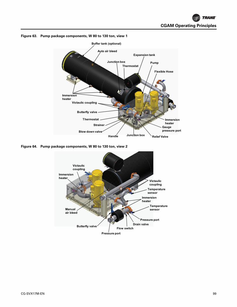
CGAM Operating Principles
Figure 63. Pump package components, W 80 to 130 ton, view 1
Immersionheater
Handle
Butterfly valve
Thermostat
Blow down valve
Strainer
Junction box
Gaugepressure port
Immersionheater
Relief Valve
Flexible Hose
Expansion tank
PumpJunction boxThermostat
Auto air bleed
Victaulic coupling
Buffer tank (optional)
Figure 64. Pump package components, W 80 to 130 ton, view 2
Pressure port
Temperaturesensor
Flow switchButterfly valve
Victauliccoupling
Victauliccoupling
Manualair bleed
Pressure port
Immersionheater
Drain valve
Temperaturesensor
Immersionheater
CG-SVX17M-EN 99

CGAM Operating Principles
Buffer Tank Components - Optional
Partial Heat Recovery Components
Figure 65. Buffer tank components, slant 20 to 35 ton and V 40 to 70 ton
Junction box
Pressureport
Immersion heater
Victaulic couplingAuto air bleed Auto air bleed
Thermostat
Victauliccoupling
Figure 66. Partial heat recovery components, slant 20 to 35 ton
PressureTransducer
SchraderValve
HPCVictaulic Coupling
TemperatureSensor
Drain Valve BPHE
Temperature Sensor
Manual Air Bleed
ImmersionHeater
100 CG-SVX17M-EN

CGAM Operating Principles
Figure 67. Partial heat recovery components, V 40 to 70 ton
HPC
Temperature Sensor
Pressure Transducer
Schrader Valve
BPHE
Manual Air Bleed
Drain Valve
Immersion Heater
Victaulic Couplings
Figure 68. Partial heat recovery components — W 80 to 130 ton
Pressure Transducer Schrader Valve
HPC
Victaulic Coupling
Temperature Sensor
Drain ValveBPHE
Temperature Sensor
Manual Air Bleed
Immersion Heater
CG-SVX17M-EN 101

CGAM Operating Principles
Refrigerant Cycle
The refrigeration cycle of the Model CGAM chiller is conceptually similar to other Trane air-cooled chiller products. The CGAM chiller uses a brazed plate evaporator and an air-cooled condenser. The compressors use suction gas cooled motors and an oil management system to provide almost oil-free refrigerant to the condenser and evaporator for maximum heat transfer while lubricating and sealing compressor bearings. The lubrication system helps to assure long compressor life and contributes to quiet operation.
Refrigerant condensers in the air-cooled heat exchanger which is available in three configurations—slant, V and W—based on the CGAM nominal tonnage cooling capacity. Liquid refrigerant is metered into the brazed plate evaporator using an electronic expansion valve to maximize chiller efficiency at full and part load operation.
The CGAM chiller is equipped with a unit-mounted starter and control panel. Microprocessor-based unit control modules (Trane Tracer® CH530) provide accurate chilled water control and provide monitoring, protection and adaptive limit functions. The adaptive nature of the controls intelligently prevent the chiller from operating outside of its limits, or compensates for unusual operating conditions while keeping the chiller running rather than simply shutting off the chiller. If problems do occur, the CH530 controls provide diagnostic messages to help the operator in troubleshooting.
Refrigerant Cycle Description
The CGAM refrigeration cycle is described using the pressure-enthalpy chart shown in Figure 69. Key State Points 1 through 5 are indicated on the chart. A schematic showing refrigerant components throughout the system is shown in Figure 69.
Refrigerant evaporation occurs in the brazed plate evaporator. Metered refrigerant vaporizes as it cools the chilled water or liquid flowing through the evaporator passages. The refrigerant vapor leaves the evaporator as superheated gas. State Point 1.
Refrigerant vapor generated in the evaporator flows to the compressor suction manifold where it enters and flows across the compressor motor windings to provide cooling. The vapor is then compressed in the compressor scroll chambers and discharged. Oil from the compressor sump lubricates the bearings and seals the small clearances between the compressor scrolls. Refrigerant vapor is discharged to the air-cooled condenser at State Point 2.
After the refrigerant vapor condenses into liquid (State Points 3 and 4) it is returned to the evaporator (State Point 5) where the refrigerant again flashes into vapor and the refrigeration cycle repeats.
Figure 69. Pressure/enthalpy curve
Oil System Operation (CGAM)
The oil is efficiently separated inside the scroll compressor and will remain in the scroll compressor during all run cycles. Between 1-2% of the oil circulates around with the refrigerant.
Sensor Requirements
Discharge temperature sensor is required for units with the following options:
• Low Temperature Process (model number digit 21 = B)
• Ice-Making (model number digit 21 = C)
• Low Leaving Water (model number digit 21 = D)
• Partial Heat Recovery with Fan Control (model number digit 24 = 1)
• Heat Pump (applicable only to units built in Epinal)
Pres
sure
Enthalpy
Liquid
Gas
1
234
5
102 CG-SVX17M-EN

Controls Interface
CH530 Communications
Overview
The Trane CH530 control system that runs the chiller consists of several elements:
• The main processor collects data, status, and diagnostic information and communicates commands to the starter module and the LLID (for Low Level Intelligent Device) bus. The main processor has an integral display (DynaView™).
• Low level intelligent device (LLID) bus. The main processor communicates to each input and output device (e.g. temperature and pressure sensors, low voltage binary inputs, analog input/output) all connected to a four-wire bus, rather than the conventional control architecture of signal wires for each device.
• The communication interface to a building automation system (BAS).
• A service tool to provide all service/maintenance capabilities.
Main processor and service tool (TechView™) software is downloadable from www.trane.com. The process is discussed later in this section under TechView Interface.
DynaView™ provides bus management. It has the task of restarting the link, or filling in for what it sees as “missing” devices when normal communications has been degraded. Use of TechView may be required.
The CH530 uses the IPC3 protocol based on RS485 signal technology and communicating at 19.2 Kbaud to allow 3 rounds of data per second on a 64-device network. A typical four-compressor CGAM will have around 30 devices.
Most diagnostics are handled by the DynaView™. If a temperature or pressure is reported out of range by a LLID, the DynaView™ processes this information and calls out the diagnostic. The individual LLIDs are not responsible for any diagnostic functions.
Note: It is imperative that the CH530 Service Tool (TechView) be used to facilitate the replacement of any LLID or reconfigure any chiller component. TechView is discussed later in this section.
Controls Interface
Each chiller is equipped with a DynaView™ interface. The DynaView™ has the capability to display information to the operator including the ability to adjust settings. Multiple screens are available and text is presented in multiple languages as factory-ordered or can be easily downloaded from www.trane.com.
TechView can be connected to the DynaView™ module and provides further data, adjustment capabilities, diagnostics information using downloadable software.
DynaView Interface
The DynaView™ enclosure design is weatherproof and made of durable plastic for use as a device on the outside of the unit.
The display on DynaView™ is a 1/4 VGA display with a resistive touch screen and an LED backlight. The display area is approximately 4 inches wide by 3 inches high (102mm x 60mm).
Key Functions
In this touch screen application, key functions are determined completely by software and change depending upon the subject matter currently being displayed. The basic touch screen functions are outlined below.
Radio Buttons
Radio buttons show one menu choice among two or more alternatives, all visible. The radio button model mimics the buttons used on old-fashioned radios to select stations. When one is pressed, the one that was previously pressed “pops out” and the new station is selected. In the DynaView™ model the possible selections are each associated with a button. The selected button is darkened, presented in reverse video to indicate it is the selected choice. The full range of possible choices as well as the current choice is always in view.
Spin Value Buttons
Spin values are used to allow a variable setpoint to be changed, such as leaving water setpoint. The value increases or decreases by touching the increment (+) or decrement (-) arrows.
Action Buttons
Action buttons appear temporarily and provide the user with a choice such as Enter or Cancel.
Hot Links
Hot links are used to navigate from one view to another view.
File Folder Tabs
File folder tabs are used to select a screen of data. Just like tabs in a file folder, these serve to title the folder/screen selected, as well as provide navigation to other screens. In DynaView™, the tabs are in one row across the top of the display. The folder tabs are separated from the rest of the display by a horizontal line. Vertical lines separate the tabs from each other. The folder that is selected has no horizontal line under its tab, thereby making it look like a part of the current folder (as would an open folder in a file cabinet). The user selects a screen of information by touching the appropriate tab.
CG-SVX17M-EN 103

Controls Interface
Display Screens
Basic Screen Format
The basic screen format appears as:
The file folder tabs across the top of the screen are used to select the various display screens.
Scroll arrows are added if more file tabs (choices) are available. When the tabs are at the left most position, the left navigator will not show and only navigation to the right will be possible. Likewise when the right most screen is selected, only left navigation will be possible.
The main body of the screen is used for description text, data, setpoints, or keys (touch sensitive areas). The Chiller Mode is displayed here.
The double up arrows cause a page-by-page scroll either up or down. The single arrow causes a line by line scroll to occur. At the end of the page, the appropriate scroll bar will disappear.
A double arrow pointing to the right indicates more information is available about the specific item on that same line. Pressing it will bring you to a subscreen that will present the information or allow changes to settings.
The bottom of the screen (Fixed Display) is present in all screens and contains the following functions. The left circular area is used to reduce the contrast/viewing angle of the display. The right circular area is used to increase the contrast/viewing angle of the display. The contrast may require re-adjustment at ambient temperatures significantly different from those present at last adjustment.
The other functions are critical to machine operation. The AUTO and STOP keys are used to enable or disable the chiller. The key selected is in black (reverse video). The chiller will stop when the STOP key is touched and after completing the Shutting Down mode.
Touching the AUTO key will enable the chiller for active cooling if no diagnostic is present. (A separate action must be taken to clear active diagnostics.)
The AUTO and STOP keys, take precedence over the Enter and Cancel keys. (While a setting is being changed, AUTO and STOP keys are recognized even if Enter or Cancel has not been pressed.)
The ALARMS button appears only when an alarm is present, and blinks (by alternating between normal and reverse video) to draw attention to a diagnostic condition. Pressing the ALARMS button takes you to the corresponding tab for additional information.
Auto, Stop/Immediate Stop
The Auto and Stop keys will be presented as radio buttons within the persistent key display area. The selected key will be black.
The chiller will stop when the Stop key is touched, entering the Run Unload mode. An informational screen will be displayed for 5 seconds indicating that a second depression of an “Immediate Stop” key during this time period will result in an immediate stop. Pressing the “Immediate Stop” key while the immediate stop screen is displayed, will cause the unit to stop immediately, skipping operational pumpdown.
Touching the Auto key will arm the chiller for active cooling if no diagnostic is present. As in UCP2, a separate action must be taken to clear active diagnostics.
The AUTO and STOP, take precedence over the ENTER and CANCEL keys. (While a setting is being changed, AUTO and STOP keys are recognized even if ENTER or CANCEL has not been pressed.
Diagnostic Annunciation
When an active diagnostic is present, an Alarms key will be added to the persistent display area. This key will serve two purposes. The first purpose will be to alert the
File folder tabs
Page scroll(up)
Line scroll(up/down)
Page scroll(down)
Tab navigator
Radio buttons
Contrast control(darker)
Contrast control(lighter)
NOTICE:
Equipment Damage!
Do NOT enable/disable the chiller by removing water flow or equipment damage can occur.
104 CG-SVX17M-EN

Controls Interface
operator that a diagnostic exists. The second purpose is to provide navigation to a diagnostic display screen.
A complete listing of diagnostics and codes is included in the Diagnostic Section.
Manual Override Exists
An indicator to present the presence of a manual override will share space with the Alarms enunciator key. While a manual override exists, the space used for the Alarms key will be occupied by a “Manual” icon, that will display solid inverse color similar to the appearance of the Alarms enunciator. An Alarm will take precedence of the Manual, until the reset of active alarms, at which point the Manual indicator would re-appear if such an override exists.
If the Manual indicator is pressed, the Manual Control Settings screen will be displayed.
Main Screen
The Main screen is a “dashboard” of the chiller. High level status information is presented so that a user can quickly understand the mode of operation of the chiller.
The Chiller Operating Mode will present a top level indication of the chiller mode (i.e. Auto, Running, Inhibit, Run Inhibit, etc.). The “additional info” icon will present a subscreen that lists in further detail the subsystem modes.
The Main screen shall be the default screen. After an idle time of 30 minutes the CH530 shall display the Main screen with the first data fields.
The remaining items (listed in the following table) will be viewed by selecting the up/down arrow icons.
Chiller Operating Mode
The machine-operating mode indicates the operational status of the chiller. A subscreen with additional mode summary information will be provided by selection of an additional information icon (>>). The operating mode line will remain stationary while the remaining status items scroll with the up/down arrow keys.
Active Chilled Water Setpoint
The active chilled water setpoint is the setpoint that is currently in use. It results from the logical hierarchy of setpoint arbitration by the main processor. It will be displayed to 0.1 degrees Fahrenheit or Celsius.
Touching the double arrow to the left of the Active Chilled Water Setpoint will take the user to the active chilled water setpoint arbitration sub-screen.
Table 63. Main screen data fields table
Description Units Resolution
Chiller Mode (>> submodes) enumeration
Circuit Mode (>> submodes) enumeration
Circuit 1 Mode (>> submodes) enumeration
Circuit 2 Mode (>> submodes) enumeration
Evap Ent/Lvg Water Temp F / C 0.1
Active Chilled Water Setpoint (>>source) F / C 0.1
Active Hot Water Setpoint (>>source) F / C 0.1
Active Demand Limit Setpoint (>>source) % 1
Outdoor Air Temperature F / C 0.1
Software Type enumeration Scroll
Software Version X.XX
CG-SVX17M-EN 105

Controls Interface
Active Chilled Water Subscreen
The active chilled water setpoint is that setpoint to which the unit is currently controlling. It is the result of arbitration between the front panel, BAS, schedule, external, and auxiliary setpoints (schedule and auxiliary not shown in the following diagram), which in turn may be subjected to a form of chilled water reset.
The chilled water reset status area in the right most column will display one of the following messages
• Return
• Constant Return
• Outdoor
• Disabled
The left column text “Front Panel”, “BAS” or “Schedule”, “External”, “Auxiliary”, “Chilled Water Reset”, and “Active Chilled Water Setpoint” will always be present regardless of installation or enabling those optional items. In the second column “-----” will be shown if that option is Not Installed, otherwise the current setpoint from that source will be shown.
Setpoints that are adjustable from the DynaView™ (Front Panel Chilled Water Setpoint, Auxiliary Chilled Water Setpoint) will provide navigation to their respective setpoint change screen via a double-arrow to the right of the setpoint source text. The setpoint change screen will look identical to the one provided in the Chiller Setpoints screen. The “Back” button on the setpoint change screen provides navigation back to the setpoint arbitration screen.
The “Back” button on the setpoint arbitration screen provides navigation back to the chiller screen.
Other Active Setpoints
The Active Demand Limit Setpoint will behave the same was as the Active Chilled Water Setpoint, except that its units are in percent and there is an Ice Building source in place of the Auxiliary source. Front Panel Demand Limit Setpoint will provide navigation to its setpoint change screen.
Password-Protected Settings
The user can change some settings from the DynaView™ display on the chiller. Other settings are password-protected. In order to change these setting the password is 314.
Settings Screen
The Settings screen provides a user the ability to adjust settings necessary to support daily tasks. The layout provides a list of sub-menus, organized by typical subsystem. This organization allows each subscreen to be shorter in length which should improve the user's navigation.
A sample Settings screen is a list of the subsystems as shown below.
Settings Sub-Screens - Table of Text, Data,
Ranges, etc.
Below is the table of text, resolution, field size, enumerated selections, and data for Settings subscreens. See the functional specification “CGAM Settings and Setpoints” for further information such as ranges and operation.
Table 64. Unit
DescriptionResolution or (Enumerations) Units
Front Panel Cool Cool Enum
Front Panel Chilled Water Setpt: + or - XXX.X Temperature
Auxiliary Chilled Water Setpt: + or - XXX.X Temperature
Front Panel Demand Limit Setpt: XXX Percent
Front Panel Ice Build Cmd: On/Auto Enum
Front Panel Ice Term Setpt: + or - XXX.X Temperature
Front Panel Noise Stb Cmd: On/Auto Enum
Setpoint Source:(BAS/Ext/FP, Ext/ Front Panel, Front Panel), BAS/Ext/FP
Enum
106 CG-SVX17M-EN

Controls Interface
Table 65. Feature settings
Description
Resolution or (Enumerations), Default Units
Power-Up Start Delay: 10 seconds Seconds (MM:SS)
Cool Low Ambient Lockout: (Enable, Disable), Enable Enum
Cool Low Ambient Lockout Stpt: + or - XXX.X Temperature
Water Pump Off Delay: 1 minute Minutes (HH:MM)
Ice Building: (Enable, Disable), Disable Enum
PHR Fan Control: (Enable, Disable), Disable Enum
Local Time of Day Schedule Subscreen (see below)
External/BAS Subscreen (see below)
Chilled Water Reset Subscreen (see below)
Table 66. External/BAS feature settings (subscreen of feature settings)
Description
Resolution or (Enumerations), Default Units
Ext Chilled Setpt: (Enable, Disable), Disable Enum
Ext Demand Limit Setpoint: (Enable, Disable), Disable Enum
Max Capacity Debounce Time: 30 seconds Seconds (MM:SS)
Limit Annunc Debounce Time: 30 seconds Seconds (MM:SS)
LCI-C Diag Encoding: (Text, Code) Text Enum
LCI-C Diag Language:(English, Selection 2, Selection 3) English (0)
Enum
Table 67. Chilled water reset feature settings (subscreen of feature settings)
Description
Resolution or (Enumerations), Default Units
Chilled Water Reset:(Const Return, Outdoor, Return, Disable), Disable
Enum
Return Reset Ratio: XXX Percent
Return Start Reset: XXX.X Temperature
Return Maximum Reset: XXX.X Temperature
Outdoor Reset Ratio: XXX Percent
Outdoor Start Reset: XXX.X Temperature
Outdoor Maximum Reset: XXX.X Temperature
Table 68. Control settings
Description
Resolution or (Enumerations), Default Units
Cooling Design Delta Temp: XXX.X Delta Temperature
Heating Design Delta Temp: XXX.X Delta Temperature
Differential to Start: XXX.X Delta Temperature
Differential to Stop: XXX.X Delta Temperature
Staging Deadband Adjustment: XXX.X Delta Temperature
Capacity Control Softload Time: 120 seconds Seconds (MM:SS)
Circuit Staging Option:
(Bal Starts/Hrs, Circuit 1 Lead, Circuit 2 Lead), Bal Starts/Hrs
Enum
Compressor Staging Option: (Fixed, Bal Starts/Hrs) Enum
Leaving Water Temp Cutout: XX.X Temperature
Low Refrigerant Temp Cutout: XX.X Temperature
Evap Flow Overdue Wait Time: 30 seconds Seconds (MM:SS)
Disch Press Limit Setpt: 85% Percent
Disch Press Limit Unload Setpt: 97% Percent
Table 69. System manual control settings
Description
Resolution or (Enumerations), Default Units Monitor Value
Evap Water Pump (Auto, On), Auto Enum
1) Evap Flow status2) Override Time Remaining
Clear Restart Inhibit Timer (Clear Timer)
1) Restart Inhibit Time (composite value)
Capacity Control
(Auto, Manual) Auto Enum
Binding Special Special None
Table 70. Circuit manual control settings
Description
Resolution or (Enumerations), Default Units
Monitor Value
Front Panel Ckt Lockout(Not Locked Out, Locked Out), Not Locked Out
Enum
Cprsr A Lockout(Not Locked Out, Locked Out), Not Locked Out
Enum
Cprsr B Lockout(Not Locked Out, Locked Out), Not Locked Out
Enum
Cprsr C Lockout(Not Locked Out, Locked Out), Not Locked Out
Enum
CG-SVX17M-EN 107

Controls Interface
Local Time of Day Schedule
Screen
To access the optional Local Time of Day Schedule Screen it must be configured in TechView™. This option will then be shown under the Feature Settings screen.
This screen shows the overall feature enable/disable setting, plus a listing of all 10 events, including their event time and active days of the week.
Local Settings Event Screen
This screen displays the details for a particular event, including the active days, event time, and the Local Schedule arbitrated setpoints. Selecting a given item will allow the user to modify it.
Event Enable/Disable Screen
Event Active Days Screen
This screen is unusual because it does not use radio buttons, which only allow one active selection at a time. These buttons are more like “selection buttons” or check boxes. The user can select any combination of days, or none at all.
Manual EXV Control: (Auto, Manual), Auto Enum
Manual EXV Position Cmd: XXX Percent
EXV StatusSuction Pressure
Cooling EXV Manual Ctrl: (Auto, Manual), Auto Enum
Cooling EXV Manual Position Cmd: XXX Percent
EXV StatusSuction Pressure
Cprsr A Pumpdown
Status: (Avail, Not Avail, Pumpdown)Override Subscreen command buttons:(Abort, Pumpdown) - button is either grayed out or not shown if not available
Enum Suction Pressure
Cprsr B Pumpdown
Status: (Avail, Not Avail, Pumpdown)Override Subscreen command buttons:(Abort, Pumpdown) - button is either grayed out or not shown if not available
Enum Suction Pressure
Cprsr C Pumpdown
Status: (Avail, Not Avail, Pumpdown)Override Subscreen command buttons:(Abort, Pumpdown) - button is either grayed out or not shown if not available
Enum Suction Pressure
Table 70. Circuit manual control settings (continued)
Description
Resolution or (Enumerations), Default Units
Monitor Value
108 CG-SVX17M-EN

Controls Interface
Event Time Screen
Event Arbitrated Settings Screens
For analog setpoints, the screen is slightly different than the standard screen, because there are two additional buttons - “Used” and “Not Used”. Selecting “Used” will make the setting valid and allow the user to change the value. Selecting “Not Used” will make the setting invalid, and will not allow the user to change the value.
Upon selecting a Settings list all setpoints available to change and the current value appear. Operator selects a setpoint by touching either the verbal description or setpoint value, causing the screen to switch to either Analog Settings Subscreen or Enumerated Settings Subscreen.
Analog Setting Subscreens
Analog Settings Subscreen displays the current value of the chosen setpoint in the upper ½ of the display. It is displayed in a changeable format consistent with its type. Binary setpoints are considered to be simple two state enumerations and will use radio buttons. Analog setpoints are displayed as spin buttons. The lower half of the screen is reserved for help screens.
All setpoint subscreens will execute the equivalent of a Cancel key if any display activities cause the subscreen to be left before a new setpoint is entered. E.g. If Alarms key
Table 71. Display settings
DescriptionResolution or (Enumerations), Default Units
Date Format (“mmm dd, yyyy”, “dd-mmm-yyyy”), “mmm dd, yyyy Enum
Date4
Time Format (12-hour, 24-hour), 12-hour Enum
Time of Day4
Keypad/Display Lockout3 (Enable, Disable), Disable Enum
Display Units (SI, English), English Enum
Pressure Units (Absolute, Gauge), Gauge Enum
Local Atmospheric Pressure: XXX.X
Pressure (always absolute)
Language1 (English, Selection 2, Selection 3), English (0) Enum
(1) Language choices are dependent on what the Service Tool has setup in the Main Processor. Get Radio Button names from Main Processor setups. Language selections will include English and qty 2 alternate as loaded by TechView™.
(2) Temperatures will be adjustable to 0.1 deg F or C. The Main Processor will provide the minimum and maximum allowable value.
(3) Enables a DynaView™ Lockout screen. All other screens time-out in 30 minutes to this screen. The DynaView™ Lockout Screen will have 0-9 keypad to permit the user to re-enter the other DynaView™ screens with a fixed password. See below for further details.
(4) The Date and Time setup screen formats deviate slightly from the stan-dard screens defined above. See the alternate screen layouts below.
(5) Language shall always be the last setting listed on the Control Settings menu (which will also always be the last item listed on the Settings menu list). This will allow a user to easily find language selection if look-ing at an unrecognizable language.
(6) The pump on mode terminates after 60 minutes.
Table 71. Display settings (continued)
DescriptionResolution or (Enumerations), Default Units
CG-SVX17M-EN 109

Controls Interface
is pressed before a new setpoint is entered, new setpoint will be cancelled. The same applies to any time-outs.
Pressing the Auto or Stop keys will not cause a cancel since the setpoint subscreen is not left on this action.
Enumerated Settings Subscreen
The enumerated setpoint subscreen has no cancel or enter key. Once a radio key is depressed the item is immediately set to the new enumeration value.
Mode Override Subscreens
The Mode Override subscreen has no cancel or enter key. Once a radio key is depressed that new value is immediately assumed.
Mode Override for Enumerated Settings is shown below:
Date/Time Subscreen
The setpoint screen for setting up the CH530 date is shown below: The user must select Day, Month, or Year and then use the up/down arrows to adjust.
The setpoint screen for setting up the CH530 time with a 12 hour format is shown below. User must select Hour, or Minute, then use up/down arrows to adjust. Adjusting hours will also adjust am/pm.
110 CG-SVX17M-EN

Controls Interface
Lockout Screen
The DynaView™ Display and Touch Screen Lock screen is shown. This screen is used if the Display and Touch Screen Lock feature is Enabled. Thirty minutes after the last key stroke this screen will be displayed and the Display and Touch Screen will be locked out until “159 Enter” is entered.
Until the proper password is entered there will be no access to the DynaView™ screens including all reports, all setpoints, and Auto/Stop/Alarms/Interlocks. The password “159” is not programmable from either DynaView™ or TechView™.
If the Display and Touch Screen Lock feature is Disabled, a similar screen including “Enter 159 to Unlock” will show if the MP temperature is approximately less than 32°F (0°C) and it has been 30 minutes after the last key stroke. Note: the main processor is equipped with an on-board temp sensor which enables the ice protection feature (OAT is not required).
Freezing rain can form on the touch panel and actuate the touch screen as the rain freezes on its surface. A specific pattern of key presses will avoid this issue.
Reports
The Reports tab will allow a user to select from a list of possible reports headings (i.e. Custom, ASHRAE Guideline 3, Refrigerant, etc.) Each report will generate a list of status items as defined in the tables that follows:
Historic Diagnostics are also included in this menu.
Table 72. Report name: system evaporator
Description Resolution Units
Evap Entering Water Temp: + or - XXX.X Temperature
Evap Leaving Water Temp: + or - XXX.X Temperature
Evap Pump Inverter 1 Run Cmd: On, Off Enumeration
Evap Pump 1 Command: On, Off Enumeration
Evap Pump 2 Command: On, Off Enumeration
Evap Water Flow Switch Status: Flow, No Flow Enumeration
Table 73. Report name: circuit evaporator
Description Resolution Units
Suction Pressure XXX.X Pressure
Suction Saturated Rfgt Temp: + or - XXX.X Temperature
Suction Temperature: + or - XXX.X Temperature
Evap Approach Temp: + or - XXX.X Temperature
EXV Position Status: XXX.X Percent
Heating EXV Position Status: XXX.X Percent
Table 74. Report name: system condenser
Description Resolution Units
Outdoor Air Temperature: + or - XXX.X Temperature
Heat Rcvy Entering Water Temp: + or - XXX.X Temperature
Heat Rcvy Leaving Water Temp: + or - XXX.X Temperature
Table 75. Report name: circuit condenser
Description Resolution Units
Discharge Pressure: XXX.X Pressure
Discharge Saturated Rfgt Temp: + or - XXX.X Temperature
Discharge Temperature: + or - XXX.X Temperature
Cond Approach Temp: + or - XXX.X Temperature
Current Air Flow: XXX.X Percent
Table 76. Report name: system compressor
Description Resolution Units
Chiller Running Time: XXXX:XX hr:min
Table 77. Report name: circuit compressor
Description Resolution Units
Compressor A Starts: XXXX Integer
Compressor A Running Time: XXXX:XX hr:min
Compressor B Starts: XXXX Integer
Compressor B Running Time: XXXX:XX hr:min
Compressor C Starts: XXXX Integer
Compressor C Running Time: XXXX:XX hr:min
CG-SVX17M-EN 111

Controls Interface
Power Up and Self Tests
Power-Up DynaView
DynaView™ will progress through three Power-Up screens:
First Screen, Application Status, Boot Software P/N, Self Test and Application Time Stamp.
This screen will display for 3-10 seconds. This screen will give the status of the Application software, the Boot Software P/N, display Self Test results and display the Application Part Number (CGAM 6200-0450-01). The contrast will also be adjustable from this screen. The message “Selftest Passed” may be replaced with “Err2: RAM Error” or “Err3: CRC Failure”.
Display Formats
Temperature settings can be expressed in F or C, depending on Display Units settings.
Pressure settings can be expressed in psia, psig, kPaa (kPa absolute), or kPag (kPa gauge) depending on Display Units settings.
Dashes (“-----”) appearing in a temperature or pressure report, indicates that the value is invalid or not applicable.
Languages
The languages for DynaView™ will reside in the main processor. The main processor will hold three languages, English, and two alternate languages. The service tool (TechView™) will load the main processor with user selected languages from a list of available translations.
TechView
TechView™ is the PC (laptop) based tool used for servicing Tracer CH530. Technicians that make any chiller control modification or service any diagnostic with Tracer CH530 must use a laptop running the software application “TechView.” TechView is a Trane application developed to minimize chiller downtime and aid the technicians understanding of chiller operation and service requirements.
Table 78. Report name: system ASHRAE chiller log
Description Resolution Units
Current Time/Date: XX:XX mmm dd, yyyy Date / Time
Chiller Mode: Enum
Active Chilled Water Setpoint: XXX.X Temperature
Active Hot Water Setpoint: XXX.X Temperature
Evap Entering Water Temp: XXX.X Temperature
Evap Leaving Water Temp: XXX.X Temperature
Evap Water Flow Switch Status: Enum
Outdoor Air Temperature: XXX.X Temperature
Active Demand Limit Setpoint: XXX Percent
Table 79. Report name: circuit ASHRAE chiller log
Description Resolution Units
Circuit Mode: Enum
Suction Pressure: XXX.X Pressure
Suction Saturated Rfgt Temp: XXX.X Temperature
Evap Approach Temp: XXX.X Temperature
Discharge Pressure: XXX.X Pressure
Discharge Saturated Rfgt Temp: XXX.X Temperature
Cond Approach Temp: XXX.X Temperature
Compressor A Starts: XXXX Integer
Compressor A Running Time: XX:XX Hours: Minute
Compressor B Starts: XXXX Integer
Compressor B Running Time: XX:XX Hours: Minute
Compressor C Starts: XXXX Integer
Compressor C Running Time: XX:XX Hours: Minute
112 CG-SVX17M-EN

Controls Interface
Important: Performing any Tracer CH530 service functions should be done only by a properly trained service technician. Please contact your local Trane service agency for assistance with any service requirements.
TechView software is available via Trane.com. (http://www.trane.com/COMMERCIAL/DesignAnalysis/TechView.aspx?i=1435)
This download site provides a user the TechView installation software and CH530 main processor software that must be loaded onto your PC in order to service a CH530 main processor. The TechView service tool is used to load software into the Tracer CH530 main processor.
Minimum PC requirements to install and
operate TechView
• Microsoft® Windows® XP Professional, Windows Vista Business or Windows 7 Enterprise operating system, Windows 10
• Internet Explorer 6.0 or higher
• USB 2.0 or higher
• Pentium II, III or higher processor
• 128Mb RAM minimum for TechView™, 1G recommended for total Windows system
• 1024 x 768 resolution of display
• CD-ROM (optional for copying TechView install to CD)
• 56K modem (optional for internet connection)
• ROVER USB-to-Serial (USB to 9-pin male)
Note: TechView™ was designed for the preceding listed laptop configuration. Any variation will have unknown results. Therefore, support for TechView is limited to only those operating systems that meet the specific configuration listed here. Only computers with a Pentium II class processor or better are supported; Intel Celeron, AMD, or Cyrix processors have not been tested.
TechView™ is also used to perform any CH530 service or maintenance function. Servicing a CH530 main processor includes:
• Updating main processor software
• Monitoring chiller operation
• Viewing and resetting chiller diagnostics
• Low Level Intelligent Device (LLID) replacement and binding
• Main processor replacement and configuration modifications
• Setpoint modifications
• Service overrides
TechView Software Download, Installation
This information can also be found at http://www.trane.com/COMMERCIAL/DesignAnalysis/TechView.aspx?i=1435.
1. Create a folder called “CH530” on your (C:\CH530) on your hard drive. This \CH530 folder is the standard recommended location for the installation file. Storing the installation file in this location helps you remember where it is stored and makes it easier for technical support personnel to assist you.
2. Click the link for the latest version on the TechView™ Software Download page. Enter your name, e-mail address and other required information. Click Submit.
3. A download link will be sent to the e-mail address provided. Before you click the link please note:
• Sent link may only be used one time.
• Internet options must be set correctly to allow download. To verify correct setting:– Open Internet Explorer Browser– Click Tools– Select Internet Options– Select Security tab– Click on Internet zone– Click Custom Level button– Scroll to Downloads section– Verify/Enable “Automatic prompting for file
downloads”– Click OK– Click YES on warning window– Click Apply, then OK
Note: If this setting is incorrect, you may or may not receive an error message during download attempt.
4. Click the download link in the e-mail message.
• If the download window does not open immediately, please look for a yellow highlighted message bar/line near the top of your browser. It may contain a message such as “To help protect your security, Internet Explorer blocked this site from downloading files to your computer. Click here for options...” Click on message line to see options.
• When dialog box appears, click Save and navigate to the CH530 folder created in Step 1. Click OK.
• If you do not complete the download successfully, you will have to request another download link (Step 2).
5. Navigate to the CH530 folder created in Step 1. Double-click the installation (.exe) file. The License Agreement dialog box appears.
6. Click I Agree after reviewing License Agreement. The Choose Components dialog box appears. All components are selected by default. (These are the
CG-SVX17M-EN 113

Controls Interface
actual MP versions for all units.) Deselect any components you do not want.
Note: Deselecting components reduces the size of the installed application.
7. Click Install. A progress meter dialog box appears. An information file appears when installation is complete.
Note: Techview requires a current version of JAVA. If you do not have the current release, TechView installation will be interrupted, and you will be provided with information for required JAVA software download. Once you have completed the JAVA installation, return to Step 5 to restart installation.
Unit View
Unit view is a summary for the system organized by chiller subsystem. This provides an overall view of chiller
operating parameters and gives you an “at-a-glance” assessment of chiller operation.
The Control Panel tab displays important operating information for the unit and allows you to change several key operating parameters. The panel is divided into four or more sub-panels (depending on the number of circuits in the unit).
The Operating Mode tab displays the unit, circuit and compressor top level operating modes.
The Hours and Starts tab displays the number a hours (total) a compressor has run and the number of times the compressor has started. This window plays a key role in evaluating maintenance requirements.
Upon successful Local Connect TechView™ will display UNIT VIEW. The Unit View displays the system, control point name, value and unit of measure. It reflects active setpoints and allows you to make changes.
CGAM Unit View is shown below:
Unit View also displays, in real time, all non-setpoint data organized by tabs. As data changes on the chiller it is automatically updated in the Unit View.
Circuit/Compressor Lockout
In order to lock out a circuit the user must go to the Unit View/Circuit 1 Manual Overrides Tab and then select the Front Panel Lockout for circuit 1 and/or circuit 2. It is also possible to lockout individual compressors from the same Circuit 1 Manual Overrides Tab in this view.
Figure 70. Unit view
Figure 71. Unit view tabs
114 CG-SVX17M-EN

Controls Interface
Table 80.Unit view tabs - detail
Tab Item Type UnitsMin Value
MaxValue
Default Value
Unit Tab
Evaporator Entering Water Temperature Status Temp (°C)
Evaporator Leaving Water Temperature Status Temp (°C)
Evaporator Water Flow Switch Status Status Flow/No Flow
Outdoor Air Temperature Status Temp (°C)
Active Chilled Water Setpoint Status Temp (°C)
Active Chilled Water Setpoint Source Status BAS/External/Front Panel/Auxiliary/Schedule
Front Panel Chilled Water Setpoint Setting Temp °C (°F)Capacity Control Chilled Water Setpoint
20°C (68°F) 6.7°C (44°F)
BAS Chilled Water Setpoint Status Temp (°C)
Local Schedule Chilled Water Setpoint Status Temp (°C)
External Chilled Water Setpoint Status Temp (°C)
Auxiliary Chilled Water Setpoint Status Temp (°C)
Filtered Chilled Water Setpoint Status Temp (°C)
Active Demand Limit Setpoint Status %
Active Demand Limit Setpoint Source Status BAS/External/Front Panel/Auxiliary/Schedule
Front Panel Demand Limit Setpoint Setting % Smallest Capacity Step 100 100
BAS Demand Limit Setpoint Status %
Local Schedule Demand Limit Setpoint Status %
External Demand Limit Setpoint Status %
Active Ice Building Command Status Off /On
Front Panel Ice Building Command Setting Auto No Request Ice Building Request No Request
Active Ice Termination Setpoint Status Temp (°C)
Front Panel Ice Termination Setpoint Setting Temp °C (°F) -6.67°C (20°F) 0°C (32°F) -2.78°C (27°F)
Manual Override Exists Status False/True
Setpoint Source Setting BAS/Ext/FP
Circuit 1 Tab
Suction Pressure Status Pressure (kPa)
Discharge Pressure Status Pressure (kPa)
Suction Saturated Refrigerant Temperature Status Temp (°C)
Suction Temperature Status Temp (°C)
Discharge Saturated Refrigerant Temperature Status Temp (°C)
Discharge Temperature Status Temp (°C)
Condenser Approach Temperature Status Temp (°C)
Evaporator Approach Temperature Status Temp (°C)
EXV Position Status (%) Status %
Circuit 2 Tab
Suction Pressure Status Pressure (kPa)
Discharge Pressure Status Pressure (kPa)
Suction Saturated Refrigerant Temperature Status Temp (°C)
Suction Temperature Status Temp (°C)
Suction Superheat Status Delta Temp (°C)
Discharge Saturated Refrigerant Temperature Status Temp (°C)
Discharge Temperature Status Temp (°C)
CG-SVX17M-EN 115

Controls Interface
Condenser Approach Temp Status Temp (°C)
Evaporator Approach Temp Status Temp (°C)
EXV Position Status (%) Status %
Unit Manual Overrides Tab
Manual Capacity Control Setting Auto/Manual
Manual Capacity Control Command Setting Unload/Hold/Load
Clear Restart Inhibit Setting
Maximum Restart Inhibit Time Remaining Status Time (Seconds to MM:SS)
Manual Evaporator Pump Control Setting Auto/On
Manual Evaporator Pump Override Time Status Time (Seconds to MM:SS)
Circuit 1 Manual Overrides Tab
Front Panel Lockout Setting Not Locked/Locked
Compressor A Lockout Setting Not Locked/Locked
Compressor B Lockout Setting Not Locked/Locked
Compressor C Lockout Setting Not Locked/Locked
Manual EXV Control Setting Auto/Manual
Manual EXV Control Percent Setting %
Compressor 1A Pumpdown Command Setting Abort
Compressor 1A Pumpdown Status Status Available/Not Available/In Progress/Inhibited
Compressor 1B Pumpdown Command Setting Abort/Start
Compressor 1B Pumpdown Status Status Available/Not Available/In Progress/Inhibited
Compressor 1C Pumpdown Command Setting Abort/Start
Compressor 1C Pumpdown Status Status Available/Not Available/In Progress/Inhibited
Suction Pressure Status Pressure (kPa)
Circuit 2 Manual Overrides Tab
Front Panel Lockout Setting Not Locked/Locked Auto Stop Auto
Compressor A Lockout Setting Not Locked/Locked Auto Stop Auto
Compressor B Lockout Setting Not Locked/Locked Auto Stop Auto
Compressor C Lockout Setting Not Locked/Locked Auto Stop Auto
Manual EXV Control Setting Auto/Manual
Manual EXV Control Percent Setting %
Compressor 2A Pumpdown Command Setting Abort/Start
Compressor 2A Pumpdown Status Status Available/Not Available/In Progress/Inhibited
Compressor 2B Pumpdown Command Setting Abort/Start
Compressor 2B Pumpdown Status Status Available/Not Available/In Progress/Inhibited
Compressor 2C Pumpdown Command Setting Abort/Start
Compressor 2C Pumpdown Status Status Available/Not Available/In Progress/Inhibited
Suction Pressure Status Pressure (kPa)
Feature Settings Tab
Local Atmospheric Pressure Setting Pressure (kPa) 68.9 kPa 110.3 kPa 101.4 kPa
Power-Up Start Delay Setting Time (Seconds) 0 600 0
Operational Pumpdown Temperature Setpoint Setting Temp °C (°F) -26°C (-14.8°F) -10°C (14°F) -17.78°C (0°F)
Table 80.Unit view tabs - detail (continued)
Tab Item Type UnitsMin Value
MaxValue
Default Value
116 CG-SVX17M-EN

Controls Interface
External Chilled Water Setpoint Setting Disable/Enable Disabled
External Demand Limit Setpoint Setting Disable/Enable Disabled
Limit Annunciation Debounce Time Setting Time (Seconds) 0s 3600s 1200s
Maximum Capacity Annunciation Debounce Time Setting Time (Seconds) 0s 3600s 1200s
Ice Building Feature Setting Disable/Enable Disabled
EXV Recalibration Time Setting Time (Seconds) ? ?
Capacity Control Tab
Cooling Design Delta Temperature Setting Delta Temp °C (°F) 1°C (1.8°F) 12°C (21.6°F) 5.56°C (10°F)
Differential To Start Setting Delta Temp °C (°F) 1°C (1.8°F) 6°C (10.8°F) 2.78°C (5°F)
Differential To Stop Setting Delta Temp °C (°F) 1°C (1.8°F) 7°C (12.6°F) 2.78°C(5°F)
Staging Deadband Adjustment Setting Delta Temp °C (°F) -1°C (-1.8°F) 5°C (9°F) 0°C (0°F)
Circuit Staging Option SettingBalance Strts-Hrs/Circuit 1 Lead/Circuit 2 Lead
Balance Starts Hours
Compressor Staging Option Setting Fixed Sequence/Balanced Strts-Hrs
Fixed Sequence
Compressor Start Delay Time Setting Time (Seconds) 0 s 600 s 60 s
Capacity Control Softload Time Setting Time (Seconds) 0 s 3600 s 900 s
Limits Tab
Cooling Low Ambient Lockout Setting Disable/Enable Enabled
Cooling Low Ambient Lockout Setpoint Setting Temp °C (°F) -20°C (-4°F) 20°C (68°F) -10°C (14°F)
Discharge Pressure Limit Setpoint Setting % 80% 120% 85%
Discharge Pressure Limit Unload Setpoint Setting % 90% 120% 97%
Restart Inhibit Free Starts Setting Starts 2
Restart Inhibit Start To Start Time Setting Time (Minutes) 6 min
Chilled Water Reset Tab
Chilled Water Reset Type Setting Disable/Return/Outdoor Air/Constant
Return Reset Ratio Setting % 10% 120% 50%
Return Start Reset Setting Delta Temp °C (°F) 2.22°C (36°F) 16.67°C (62°F) 5.55°C (42°F)
Return Maximum Reset Setting Delta Temp °C (°F) 0°C (32°F) 11.11°C (52°F) 2.78°C (37°F)
Outdoor Reset Ratio Setting % -80% 80% 10%
Outdoor Start Reset Setting Temp °C (°F) 10°C (50°F) 54.44°C (130°F) 32.22°C (90°F)
Outdoor Maximum Reset Setting Delta Temp °C (°F) 0°C (32°F) 11.11°C (52°F) 2.78°C (37°F)
Cooling Design Delta Temperature Setting Delta Temp °C (°F) 1°C (33.8°F) 12°C (53.6°F) 5.56°C (42°F)
Pump Control Tab
Evaporator Water Flow Switch Status Status No Flow/Flow
Evap Pump Inverter 1 Run Command Status Off/On
Evaporator Pump 1 Command Status Off/On
Evaporator Pump 2 Command Status Off/On
Evap Pump Off Delay Setting Time (Minutes) 0 min 30 min 1 min
Evap Flow Overdue Wait Time Setting Time (Seconds) 300 s 3600 s 1200 s
High Evaporator Water Temp Setpoint Setting Temp °C (°F) 55°C
Freeze Avoidance Tab
Leaving Water Temp Cutout Setting Temp °C (°F) -21.7°C (-7°F) 4.4°C (40°F) 3.3°C (38°F)
Low Refrigerant Temperature Cutout Setting Temp °C (°F) -29.4°C (-21°F) 2.22°C (36°F) -3.3°C (26°F)
Evaporator Pump Freeze Avoidance Setting Disable/Enable Enabled
Evap Pump Freeze Avoidance Adaptive Learning Setting Fixed/Adaptive Enabled
Table 80.Unit view tabs - detail (continued)
Tab Item Type UnitsMin Value
MaxValue
Default Value
CG-SVX17M-EN 117

Controls Interface
The items that can be modified show up in white. The items that cannot be modified show up in gray.
To change the setpoint enter a new value for the setpoint into the text field.
If the entered value is outside the given range, the background turns red.
If the value entered is not valid, an error message will display and the change will not occur
Evap Pump Freeze Avoidance Time Constant Setting Time (minutes) 2 min 360 min 10 min
Evap Pump Freeze Avoidance Temp Margin Setting Delta Temp °C 0°C 5°C 2°C
Starts and Hours Tab
Chiller Running Time Status Time (Sec to HH:MM)
Compressor 1A Starts Status Starts
Compressor 1A Running Time Status Time (Sec to HH:MM)
Compressor 1B Starts Status Starts
Compressor 1B Running Time Status Time (Sec to HH:MM)
Compressor 1C Starts Status Starts
Compressor 1C Running Time Status Time (Sec to HH:MM)
Compressor 2A Starts Status Starts
Compressor 2A Running Time Status Time (Sec to HH:MM)
Compressor 2B Starts Status Starts
Compressor 2B Running Time Status Time (Sec to HH:MM)
Compressor 2C Starts Status Starts
Compressor 2C Running Time Status Time (Sec to HH:MM)
Evaporator Water Pump 1 Starts Status Starts
Evaporator Water Pump 1 Running Time Status Time (Sec to HH:MM)
Evaporator Water Pump 1 Starts Status Starts
Evaporator Water Pump 1 Running Time Status Time (Sec to HH:MM)
Heat Recovery Tab
Partial heat recovery (PHR) Fan Control Setting Disable/Enable
PHR Leaving Water Temperature Setpoint Setting Temp (°C)
PHR Leaving Water Temperature Adjustment Setting Delta Temp (°C)
Generic Monitoring Tab
Generic Temp Sensor Status Temp (°C)
Generic Pressure Sensor Status Pressure (kPa)
Generic Analog Monitor Status Current (mA)
Generic Low Volt Monitor Setting Open/Closed
Generic High Volt Monitor Setting Off/On
Table 80.Unit view tabs - detail (continued)
Tab Item Type UnitsMin Value
MaxValue
Default Value
Figure 72. Fields in white Figure 73. Change setpoint
Figure 74. Change out of range
118 CG-SVX17M-EN

Controls Interface
. Diagnostics View
This window lists the active and inactive (history) diagnostics. There can be up to 60 diagnostics, both active and historic. For example, if there were 5 active diagnostics, the possible number of historic diagnostics would be 55. You can also reset active diagnostics here, (i.e., transfer active diagnostics to history and allow the chiller to regenerate any active diagnostics).
Resetting the active diagnostics may cause the chiller to resume operation.
The Active and History diagnostics have separate tabs. A button to reset the active diagnostics displays when either tab is selected.
Configuration View
This view is under the CH530 tab and displays the active configuration and allows you to make changes to the unit configuration. Configuration View allows you to define the chiller's components, ratings, and configuration settings. These are all values that determine the required installed devices, and how the chiller application is run in the main processor. For example, a user may set an option to be installed with Configuration View, which will require devices to be bound using Binding View. And when the main processor runs the chiller application, the appropriate steps are taken to monitor required inputs and control necessary outputs.
Any changes made in the Configuration View, on any of the tabs, will modify the chiller configuration when you click on the Load Configuration button (located at the base of the window). The Load Configuration button uploads the new configuration settings into the main processor.
Selecting the Undo All button will undo any configuration setting changes made during the present TechView™ connection and since the last time the Load Configuration button was selected.
Figure 75. Setpoint change failed
Figure 76. Diagnostic view
CG-SVX17M-EN 119

Controls Interface
A couple of additional tabs in Configuration View allow you to change other unit configuration options using the Options tab and the Options Setup tab. The features that are installed on the Options Tab will control what is displayed on the Options Setup tab.
Figure 77. Configuration view — CH530 tab
Table 81.Configuration view items - CH530 tab
Item Description
Basic Product Line CGAM - Air-Cooled Scroll Packaged Chiller
Unit Capacity
020 Nominal Tons023 Nominal Tons (TAI, EPL only)026 Nominal Tons030 Nominal Tons035 Nominal Tons039 Nominal Tons (EPL only)040 Nominal Tons045 Nominal Tons (EPL only)046 Nominal Tons (TAI, EPL only)052 Nominal Tons 060 Nominal Tons070 Nominal Tons080 Nominal Tons090 Nominal Tons100 Nominal Tons110 Nominal Tons120 Nominal Tons
Unit Design Sequence Factory Assigned
Manufacturing Location
Epinal, FrancePueblo, USATaicang, ChinaCuritiba, Brazil
Unit TypeStandard Efficiency/Performance (EPL only)High Efficiency/Performance
Sound PackageHigh Duty (EPL and TAI only)Standard NoiseLow Noise
Supply Power Frequency
60 Hz50 Hz
Unit Application
Standard Ambient (EPL and TAI only)Low Ambient (EPL and TAI only)High Ambient (EPL and TAI only)Wide Ambient
Heat Recovery
No Heat RecoveryPartial Heat Recovery w/ Fan ControlPartial Heat Recovery w/o Fan Control (EPL and TAI only)
Evaporator Pump Control
No Pump Flow ControlSingle Pump Fixed Speed (TAI, EPL only)Single Pump Variable Speed (TAI, EPL only)Dual Pump Fixed Speed (TAI, EPL only)Dual Pump Variable Speed
120 CG-SVX17M-EN

Controls Interface
Software View
Software view allows you to verify the version of chiller software currently running on the DynaView™ and download a new version of chiller software to the DynaView™.
You can also add up to two available languages to load into the DynaView™. Loading an alternate language file allows the DynaView™ to display its text in the selected alternate language, English will always be available.
Figure 78. Configuration view — options tab
Figure 79. Configuration view — options setup tab
Figure 80. Software view
CG-SVX17M-EN 121

Controls Interface
Binding View
Binding View allows you to assess the status of the network and all the devices connected as a whole, or the status of individual devices by using status icons and function buttons.
Binding View is essentially a table depicting what devices and options are actually discovered on the network bus (and their communication status) versus what is required to support the configuration defined by the feature codes
and categories. Binding View allows you to add, remove, modify, verify, and reassign devices and options in order to match the configuration requirements.
Whenever a device is installed, it must be correctly configured to communicate and to function as intended. This process is called binding. Some features of Binding View are intended to serve a second purpose; that is diagnosing problems with communication among the devices.
Replacing or Adding Devices
If a device is communicating but incorrectly configured, it might not be necessary to replace it. If the problem with the device is related to communication, attempt to rebind it, and if the device becomes correctly configured, it will then communicate properly.
If a device that needs to be replaced is still communicating, it should be unbound. Otherwise, it will be necessary to rebuild the CH530 network image for Binding View to discover that it has been removed. An unbound device stops communicating and allows a new device to be bound in its place.
It is good practice to turn the power off while detaching and attaching devices to the CH530 network. Be sure to keep power on the service tool computer. After power is restored to the CH530 network, the reconnect function in Binding View restores communication with the network. If the service tool computer is turned off, you must restart TechView™ and Binding View.
If a device is not communicating, the binding function displays a window to request manual selection of the device to be bound. Previously-selected devices are deselected when the function starts. When manual selection is confirmed, exactly one device must be selected; if it is the correct type, it is bound. If the desired
device cannot be selected or if multiple devices are accidentally selected, you can close the manual selection window by clicking on No and repeat the bind function.
Integrated Rapid Restart
Chiller controls are designed and engineered for Rapid Restart. Advanced features and functionality are built into the chillers. Bringing a chiller back online rapidly after a loss of power is critical to operations in mission critical environments, which demand the highest levels of reliability.
Under optimal conditions it can restart in as little as # seconds with an uninterrupted power supply (UPS) backing up the unit controls and # seconds without a UPS. 80 percent cooling load can be achieved in less than 2.5 minutes after power restoration.
Figure 81. Binding view
122 CG-SVX17M-EN

CG-SVX17M-EN 123
Pre-Start Checkout
Upon completion of installation, complete the CGAM Installation Completion Check Sheet and Request for Trane Service checklist in chapter “Log and Check Sheet,” p. 149.
Important: Start-up must be performed by Trane or an agent of Trane specifically authorized to perform start-up and warranty of Trane products. Contractor shall provide Trane (or an agent of Trane specifically authorized to perform start-up) with notice of the scheduled start-up at least two weeks prior to the scheduled start-up.

Start-Up and Shutdown
Important: Initial unit commissioning start-up must be performed by Trane or an agent of Trane specifically authorized to perform start-up and warranty of Trane products. Contractor shall provide Trane (or an agent of Trane specifically authorized to perform start-up) with notice of the scheduled start-up at least two weeks prior to the scheduled start-up.
Start-Up
If required, once the system has been operating for approximately 30 minutes and has become stabilized, complete the remaining start-up procedures, as follows:
1. Check the evaporator refrigerant pressure and the condenser refrigerant pressure under Refrigerant Report on the CH530 TechView™.
Note: The pressures are referenced to sea level (14.6960 psia). This value is adjustable in TechView.
2. Check the EXV sight glasses after sufficient time has elapsed to stabilize the chiller. The refrigerant flow past the sight glasses should be clear. Bubbles in the refrigerant indicate either low refrigerant charge or excessive pressure drop in the liquid line or a stuck open expansion valve. A restriction in the line can sometimes be identified by a noticeable temperature differential between the two sides of the restriction. Frost will often form on the line at this point. Proper refrigerant charges are shown in General Data tables.
Important: A clear sight glass alone does not mean that the system is properly charged. Also check system sub-cooling, liquid level control and unit operating pressures.
If chiller is limited by any limiting conditions, contact local Trane service organization for more information.
Seasonal Unit Start-Up Procedure
1. Verify/close all drain valves.
2. Service the auxiliary equipment according to the start-up/maintenance instructions provided by the respective equipment manufacturers.
3. Remove all air from the system (including each pass). Close the vents in the evaporator chilled water circuits.
4. Open all valves in evaporator chilled water circuits.
5. If evaporator was previously drained, vent and fill evaporator and chilled water circuit. When all air is removed (including each pass), install vent plugs in evaporator water boxes
.
Seasonal Unit Shutdown
1. Perform normal unit stop sequence using <Stop> key.
Note: Starter disconnect switch must remain closed to provide power to compressor oil sump heaters.
2. Verify that compressor oil sump heaters are installed tightly around compressor. Energize and verify heaters are operational using a temperature probe. See Table 82, p. 125. Install jumper across thermostat and verify current flow.
NOTICE:
Equipment Damage!
Ensure that the oil sump heaters are connected properly and are operating properly for a minimum of 24 hours before starting. Failure to do so may result in equipment damage.
NOTICE:
Equipment Damage!
Snow, ice, or debris build up on fans could cause
excessive imbalance and equipment damage.
Clear fans of build up prior to machine startup.
NOTICE:
Equipment Damage!
Ensure that the oil sump heaters have been operating for a minimum of 24 hours before starting. Failure to do so may result in equipment damage.
NOTICE:
Equipment Damage!
If the chiller evaporator or evaporator water piping is drained of water, the evaporator immersion heater must be de-energized. Failure to de-energize the heater will cause it to burn out.
124 CG-SVX17M-EN

Start-Up and Shutdown
Note: See “Ambient Freeze Avoidance,” p. 69 for more information.
3. Once the unit is secured, perform maintenance identified in “Maintenance,” p. 129.
Sequence of Operation
This section will provide basic information on chiller operation for common events. With microelectronic controls, ladder diagrams cannot show today’s complex logic, as the control functions are much more involved than older pneumatic or solid state controls.
Adaptive control algorithms can also complicate the exact sequence of operations. This section illustrates common control sequences.
Software Operation Overview
The Software Operation Overview shown in Figure 82 is a diagram of the five possible software states. This diagram can be though of as a state chart, with the arrows and arrow text depicting the transitions between states.
• The text in the circles is the visible top level operating mode displayed on DynaView Main tab.
• The shading of each software state circle corresponds to the shading on the time lines that show the state the chiller is in.
There are five generic states that the software can be in:
• Power Up
• Stopped
• Starting
• Running
• Stopping
Table 1. Freeze protection heater summary(a)
Heater Thermostat Jumper
Heater Description Heaters
Evap and Water Pipe Heaters
5S1 5X1-2 to 5X1-3
Evaporator 5E1
Evap Entering Water 5E4, 5E18
Evap Leaving Water 5E5, 5E19
Water Pump Piping5E6, 5E14
Partial Heat Recovery (optional)
5E10,5E11, 5E16, 5E17
Expansion Tank (included with optionalpump package)
5E7
Pump Package (optional)
5S2 5X2-1 to 5X2-2 Water Pump Piping
5E13, 5E15
Buffer Tank (optional)
5S3 Across thermostat Buffer Tank
5E2, 5E8, 5E12, 5E13
(a) Not all heaters are present on all unit configurations. See schematics and component locations in CGAM-SVE01*-EN.
Figure 1. Chiller state chart
Shutting Down
Runningor
Running Limit
Stoppedor
Run Inhibit
CGAM Sequence of Operation: Chiller State Chart
AutoCommand
Confirmed Start
Stop CommandDiagnostic
Confirmed
Shutdown
Boot and Self Test
Stop Command or Diagnostic
Autoor
Waiting to Start
Check for Differential
to Start
Check for Differential
to Stop
Releaseof Inhibit
Power Up
CG-SVX17M-EN 125

Start-Up and Shutdown
Power Up
The Power up chart shows the respective DynaView screens during a power up of the main processor. This process takes from 30 to 45 seconds depending on the number of installed Options. On all power ups, the software model will always transition through the
'Stopped' Software state independent of the last mode. If the last mode before power down was 'Auto', the transition from 'Stopped' to 'Starting' occurs, but it is not apparent to the user.
Power Up to Starting
Power up to starting diagram shows timing from a power up event to energizing the first compressor. The shortest allowable time would be under the following conditions:
• No motor restart inhibit
• Evaporator Water flow occurs quickly with pump on command
• Power up Start Delay setpoint set to 0 minutes
• Need to cool (differential to start) already exists
The above conditions would allow for a minimum power up to starting the first compressor time of about 85 seconds, depending on options installed.
Figure 2. Power up
Completing Self Test(15 Seconds)
ApplyControlPower
Starting Application(15 to 30 Seconds)
Last Modei.e. Auto
or Stoppedas Shown
Self Test Starting Application
Note: The variation in DynaView Power up time isdependent on the number of installed options.
ApplicationPresent,RunningSelftest...
ApplicationPartNumber:6200-0450-01
BootPartNumber:6200-0432-10
AValidConfigurationis Present
TracerCH530
©Trane2000-2009
Chiller Mode: AutoCircuit 1 Mode: StoppedCircuit 2 Mode: StoppedEvap Ent/Lvg Water Temp: 80.5/80.2FActive Chilled Water Setpoint: 80.5FActive Demand Limit Setpoint: 100%
Figure 3. Power up to starting
PowerApplied
Last Mode Was Auto
Auto(Waiting for Evaporator
Water Flow)
Call for Cooling: Differential to Start is met
Energize EvaporatorWater Pump Relay
Confirm Evaporator WaterFlow Within 20 minutes(10 Sec Filter)
Waiting to Start
Confirm EvaporatorWater Flow
(10 Second Filter)
Auto(Waiting for
a Need to Cool)
PowerUp
CH530Boot Time
(30 to 40 Sec)
Enforce Power UpStart Delay Timer(adj 0 to 10 mins)
Re-calibrate EXV(overdrive closed)
* Lead Circuit/Compressor is determined by:- Circuit Staging Option: Balanced Wear, Circuit 1 Lead, Circuit 2 Lead- Compressor Staging Option: Balanced Wear, Fixed Sequence
(Follows per circuit configuration)- also influenced by lockouts, restart inhibit and diagnostics present
Pre-Position EXVof Lead Circuit*
EXV stroke toPreposition
Waiting to StartStartCommandto LeadCprsr*
Waiting forDifferential to Start
Fan Pre-Startof Lead Circuit*
Wait for PressureStabilization(3 Seconds)
RunInhibited
126 CG-SVX17M-EN

Start-Up and Shutdown
Stopped to Starting
The stopped to starting diagram shows the timing from a stopped mode to energizing the compressor. The shortest allowable time would be under the following conditions:
• No motor restart inhibit
• Evaporator Water flow occurs quickly with pump on command
• Need to cool (differential to start) already exists.
The above conditions would allow the compressor to start in about 35 seconds.
Normal Shutdown to Stopped
Figure 86 shows transition from Running through a Normal (friendly) Shutdown. Dashed lines on top attempt to show final mode if you enter stop via various inputs.
Figure 4. Stopped to starting
StoppedOr
RunInhibit
StartCommand toLeadCompressor*
Chiller Set to Auto
Auto(Waiting for Evaporator
Water Flow)
Energize EvaporatorWater Pump Relay
Confirm Evaporator WaterFlow Within 20 minutes(10 Sec Filter)
Waiting to Start
Confirm EvaporatorWater Flow
(10 Second Filter)
Auto(Waiting for
a Need to Cool)
* Lead Circuit/Compressor is determined by:- Circuit Staging Option: Balanced Wear, Circuit 1 Lead, Circuit 2 Lead- Compressor Staging Option: Balanced Wear, Fixed Sequence (Follows per circuit configuration)- also influenced by lockouts, restart inhibit and diagnostics present
Pre-Position EXVof Lead Circuit*
EXV stroke toPreposition
Waiting to Start
Waiting forDifferential to Start
Fan Pre-Startof Lead Circuit*
Wait for PressureStabilization(3 Seconds)
Call for Cooling: Differential to Start is met
Figure 5. Normal shutdown to stopped or run inhibit
Running
Local StopNormal Shutdown Diagnostic*, LatchedNormal Shutdown Diagnostic*, Non-LatchedBAS StopExternal Auto-StopLocal Schedule Stop
Stoppedor
Run Inhibit
Shutting Down(Operational Pumpdown)
Shutting Down(Evaporator WaterPump Off Delay)
De-Energize PumpdownCompressors
Waiting for EXV to Close(0 to 10 Seconds)
Time out Evap Pump Off Delay(adj 0-30 minutes) De-Energize Evaporator
Water Pump
De-Energize all Non-PumpdownCompressors **
De-Energize All Fans* Normal Shutdown Diagnostic:
- Chiller Level Diagnostic- Circuit Level Diagnostic on only running circuit- Compressor Level Diagnostic on only running compressor
** Pumpdown Compressor is:- One compressor on each circuit running during Operational Pumpdown
*** If normal pumpdown termination does not occur within the Pumpdown Timeout
Close EXVConfirm PumpdownTermination. See Note***
Shutting Down(Operational Pumpdown)
Waiting for Saturated SuctionTemperature to fall to 0 Degrees F
(Less than 30 Seconds)
CG-SVX17M-EN 127

Maintenance
Perform all maintenance procedures and inspection at the recommended intervals. This will prolong the life of the chiller and minimize the possibility of malfunctions.
Use an “Operator’s Log” to record the unit’s operating history. The log serves as a valuable diagnostic tool for service personnel. By observing trends in operating conditions, an operator can anticipate and prevent problem situations before they occur.
If the unit is not operating properly during maintenance inspections, see “Diagnostics,” p. 134.
Recommended Maintenance
Weekly
Verify that compressor oil sump heaters are connected tightly around the compressor.
After the chiller has been operating for approximately 30 minutes and the system has stabilized, check the
operating pressures and temperatures and complete the following checks:
Check the evaporator and condenser refrigerant pressures in the Refrigerant Report menu of the CH530 display. Pressures are referenced at sea level (14.6960 psia).
Check the electronic expansion valve sight glasses.
Note: The electronic expansion valve is commanded closed at unit shutdown and if the unit is off, there will be no refrigerant flow through the sight glasses. Only when a circuit is running will refrigerant flow be present.
The refrigerant flow through the sight glasses should be clear. Bubbles in the refrigerant indicate either low refrigerant charge or excessive pressure drop in the liquid line. A restriction in the line can sometimes be identified by a noticeable temperature differential between the two sides of the restriction. Frost may often form on the liquid line at this point. Correct refrigerant charges are shown in the General Data Tables.
Important: A clear sight glass alone does not mean that the system is properly charged. Also check the system superheat, subcooling and unit operating pressures.
For more information, see “Refrigerant and Oil Charge Management,” p. 130.
Monthly
1. Complete all weekly maintenance procedures.
2. Measure and record the evaporator superheat.
3. Measure and record the system subcooling.
Annual
1. Complete all weekly and monthly maintenance checks.
2. Check the oil level and refrigerant charge. Routine changing of oil is not required.
3. Have a qualified laboratory perform a compressor oil analysis to determine system moisture content and acid level. This analysis is a valuable diagnostic tool.
4. Contact a qualified service provider to leak test the chiller, check operating and safety controls, and to inspect electrical components for proper operation. Leak testing my be accomplished using soap solution or with electronic or ultrasonic leak detectors.
5. Inspect all piping components for leaks and damage. Clean all water strainers.
WARNING
Hazardous Voltage - Pressurized Burning Fluid!
Failure to follow all electrical safety precautions could result in death or serious injury.
Compressors on 110 and 120 ton, extra efficiency units, have strong permanent magnet motors that have the capability to generate voltage during situations when the refrigerant charge is being migrated. This potential will be present at the motor terminals and at the load side of compressor contactors.
Before removing compressor terminal box cover for servicing, or servicing power side of control panel, CLOSE COMPRESSOR DISCHARGE SERVICE VALVE and disconnect all electric power including remote disconnects. Follow lockout/tagout procedures to ensure the power cannot be inadvertently energized.
The compressor contains hot, pressurized refrigerant. Motor terminals act as a seal against this refrigerant. Care should be taken when servicing NOT to damage or loosen motor terminals.
Do not operate compressor without terminal box cover in place.
WARNING
Hazardous Voltage!
Failure to disconnect power before servicing could result in death or serious injury. Disconnect all electric power, including remote disconnects before servicing. Follow proper lockout/tagout procedures to ensure the power can not be inadvertently energized.
128 CG-SVX17M-EN

Maintenance
6. Clean and repaint any components that show corrosion.
7. Clean the condenser coils per “Condenser Maintenance,” p. 131
.
8. Clean the condenser fans. Check the fan assemblies for proper clearance in the fan shroud openings and for motor shaft misalignment or abnormal end-play, vibration and noise.
9. Manually rotate the condenser fans to ensure that there is proper clearance on the fan shroud openings.Inspect the entire system for unusual conditions.
Refrigerant and Oil Charge
Management
Proper oil and refrigerant charge is essential for proper unit operation, unit performance, and environmental protection. Only trained and licensed service personnel should service the chiller.
Table 83 lists baseline measurements for CGAM units running at AHRI standard operating conditions. If chiller measurements vary significantly from values listed below, problems may exist with refrigerant and oil charge levels. Contact your local Trane office.
Note: Low temperature applications units will have values that vary from Table 83. Contact your local Trane office for more information.
Lubrication System
Oil Level
Oil should also be visible in the sight glass when the compressor is running. When operating, each compressor in a tandem or trio set may have a different oil level.
To check compressor oil level, refer to the label near the compressor sight glass. The compressor(s) must be off. Wait three minutes. With tandem or triple compressors the oil level will equalize after shutdown. Compressor oil level should be clearly visible within the sight glass when the compressors are off.
Important: If oil level is low, contact your local Trane office. Verify that ONLY Trane OIL00080 is used.
Oil Testing
Use Trane Oil Testing Kit KIT06815 only for testing lubricating oil in the Model CGAM chiller. Note that the POE oil used in this product is very hygroscopic and easily absorbs and retains moisture. The acceptable moisture content is less than 100 ppm and acceptable acid level is less than 0.5 TAN. Note that refrigerant and moisture is very difficult to remove from this oil using vacuum. Also note that once the seal on a container of POE oil is opened, the oil must be used.
In the event of a compressor failure, always test the oil with an acid test kit to determine whether the compressor failure was mechanical or electrical. This is important because it dictates correct cleanup procedure.
NOTICE:
Equipment Damage!
If the CGAM chiller evaporator or evaporator water piping is drained of water, the evaporator immersion heater must be de-energized. Failure to de-energize the heater will cause it to burn out.
WARNING
Rotating Components!
Failure to disconnect power before servicing could result in rotating components cutting and slashing technician which could result in death or serious injury. Disconnect all electric power, including remote disconnects before servicing. Follow proper lockout/tagout procedures to ensure the power can not be inadvertently energized.
Table 1. Typical CGAM baselines (AHRI conditions)
Measurement Baseline
Evaporator Pressure 120 psig
Evaporator Approach 5-10°F
EXV Position 40-50% open
Evaporator delta T 10°F
Evaporator Superheat 12°F
Condenser Pressure 420-440 psia
Condensing Approach Temperature 25°F
Subcooling 15-20°F
Compressor Discharge Temperature 63° or more
Compressor Suction Temperature 20° or more
Compressor RLA 100%
Table 1. Typical CGAM baselines (AHRI conditions)
Measurement Baseline
CG-SVX17M-EN 129

Maintenance
Condenser Maintenance
Microchannel Condensers
For proper operation, microchannel condenser coils must be cleaned regularly. Eliminate pollution and other residual material help to extend the life of the coils and the unit.
Regular coil maintenance, including annual cleaning, enhances the unit’s operating efficiency by minimizing compressor head pressure and amperage draw. The condenser coil should be cleaned at minimum once each year, or more if the unit is located in a “dirty” or corrosive environment.
Microchannel Condenser Coil Cleaning
Cleaning with cleansers or detergents is strongly discouraged due to the all-aluminum construction. Water should prove sufficient. Any breach in the tubes can result in refrigerant leaks.
1. Disconnect Power to the unit.
Important: Bridging between the main supports required before attempting to enter the unit. Bridging may consist of multiple 2 by 12 boards or sheet metal grating.
2. Use a soft brush or vacuum to remove base debris or surface loaded fibers from both sides of the coil.
Note: When possible, clean the coil from the opposite direction of normal air flow (inside of unit out) to push debris out.
3. Using a sprayer and water ONLY, clean the coil following the guidelines below.
a. Sprayer nozzle pressure should not exceed 580 psi.
b. The maximum source angle should not exceed 25° to the face of the coil. See Figure 87. For best results spray the microchannel perpendicular to face of the coil.
c. Spray nozzle should be approximately 1”-3” from the coil surface.
d. Use at least a 15º fan type of spray nozzle.
Note: To avoid damage from the spray wand contacting the coil, make sure the 90º attachment does not come in contact with the tube and fin as abrasion to the coil could result.
Repair/Replacement of Microchannel Coil
Microchannel coils are considerably more robust in design than tube and fin condenser coils, however they are not indestructible. When damage or a leak occurs, contact your local Trane office.
Round Tube Plate Fin Condensers
RTPF Condenser Coil Cleaning
Clean the condenser coils at least once a year or more frequently if the unit is in a “dirty” environment. A clean condenser coil will help to maintain chiller operating efficiency. Follow the detergent manufacturer's instructions to avoid damaging the condenser coils.
NOTICE:
Equipment Damage!
Do not use detergents to clean coils. Use clean water only. Use of detergents on coils could cause damage to coils.
WARNING
Hazardous Voltage!
Disconnect all electric power, including remote disconnects before servicing. Follow proper lockout/tagout procedures to ensure the power can not be inadvertently energized. Failure to disconnect power before servicing could result in death or serious injury.
WARNING
No Step Surface!
Failure to follow instruction below could result in death or serious injury. Do not walk on the sheet metal drain pan. Walking on the drain pan could cause the supporting metal to collapse, resulting in the operator/technician to fall.
Figure 1. Sprayer source angle
WARNING
Hazardous Chemicals!
Coil cleaning agents can be either acidic or highly alkaline and can burn severely if contact with skin occurs. Handle chemical carefully and avoid contact with skin. ALWAYS wear Personal Protective Equipment (PPE) including goggles or face shield, chemical resistant gloves, boots, apron or suit as required. For personal safety refer to the cleaning agent manufacturer’s Materials Safety Data Sheet and follow all recommended safe handling practices. Failure to follow all safety instructions could result in death or serious injury.
130 CG-SVX17M-EN

Maintenance
To clean the condenser coils use a soft brush and a sprayer such as a garden pump type or a high-pressure type. A high quality detergent such as Trane Coil Cleaner (Part No. CHM-00255) is recommended.
See RTAC-SVG01B-EN for maintenance and cleaning procedures.
Note: If detergent mixture is strongly alkaline (pH value greater than 8.5, an inhibitor must be added).
Evaporator Maintenance
The Trane Model CGAM liquid chiller uses a brazed plate heat exchanger (BPHE) evaporator with factory-installed electronic flow switch (IFM efector) that is positioned in the evaporator water pipe. The evaporator inlet also includes a factory-installed immersion heater for freeze protection and a water strainer that must be kept in place to keep debris out of the evaporator.
Note: Strainer maintenance is critical to proper operation and reliability. Any particles larger than 1mm entering the BPHE evaporator may cause the evaporator to fail, requiring replacement.
Acceptable BPHE evaporator water flow rate is 1.5 to 3.6 GPM per nominal unit ton capacity. To maintain 54-44°F in/out chilled water temperatures, the nominal water flow rate is 2.4 GPM/ton.
Minimum water flow rate must be maintained to avoid laminar flow, potential evaporator freezing, scaling and poor temperature control. The microprocessor and capacity control algorithms are designed to take a 10 percent change in water flow rate per minute while maintaining a ±2°F (1.1°C) leaving water temperature control accuracy. The chiller tolerates up to 30 percent per minute water flow variation as long as the flow is equal to or greater than minimum flow requirements.
Maximum water flow is 18 feet per second. Flow rates greater than this will cause excessive erosion.
The BPHE evaporator is difficult to clean should it become plugged with debris. Indications of a plugged BPHE evaporator include “wet” suction due to lack of heat exchange, loss of superheat control, depressed discharge superheat, compressor oil dilution and/or starvation and premature compressor failure.
Water Strainer Maintenance
For units with optional pump package, the factory-installed water strainer is a Y-type design with a cylindrical sieve.
An in-line strainer with a V-shaped sieve is used for units that do not have factory-installed pump package option.
The strainer is equipped with a blow-down port. The strainer is a 16 mesh (approximately 1 mm) material.
For maximum efficiency, a differential pressure gauge installed across the inlet and outlet will indicate pressure loss due to clogging and may be used as a guide to determine when cleaning is required. The taps for the pressure gauges are included as standard from the factory.
Normally when differential pressure reaches 5-10psi, the screen must be cleaned. The strainer is equipped with a blow-down port on the cover plate. To clean open and flush out until any sediment is removed.
NOTICE:
Equipment Damage!
The factory-installed immersion heater must be de-energized if the BPHE evaporator is drained of water for any reason. Failure to de-energize the immersion heater will cause it to burn out.
Figure 2. Y type strainer —
units with optional pump package
Figure 3. In-line strainer —
units without optional pump package
WATER FLOW DIRECTION
CG-SVX17M-EN 131

Maintenance
Pump Package Maintenance
Rust Prevention
Pumps not immediately placed into service, or removed from service and stored, must be properly prepared to prevent excessive rusting.
• Pump port protection plates must not be removed until the pump is ready to connect to the piping.
• Rotate the shaft periodically (at least monthly) to keep rotating element free and bearings fully functional.
• For long term storage (3 months or longer), prevent internal rust buildup and possibility of freezing by performing the following steps:
• Remove the plugs at the top and bottom of the casing.
• If water is to be drained:
• Disconnect evaporator and piping heaters.
• Drain or blow out all water.
• As an optional step, it is acceptable to rustproof or pack the casing with moisture absorbing material and cover the flanges.
When returning pumps to service
• Remove drying agent from the pump, if used.
• Reinstall plugs at the top and bottom of the casing.
• If water had been drained:
• Refill water.
• Reconnect evaporator and piping heaters.
132 CG-SVX17M-EN

Diagnostics
Explanatory Comments
Diagnostic Text:
Black text is intended for use on TechView. It has no intrinsic length limit. It should contain few or no abbreviations.
Blue (italicized) text is intended for use on DynaView. It has a 40 character length limit for English and other European languages, based on 8 pixel character width (DynaView’s display is 320 pixels wide). The text should be abbreviated as necessary to meet the length limit. Trane standard abbreviations or ASME standard abbreviations (ASME Y14.38-1999 or later) should be used wherever possible.
Orange (underlined) text is intended for use on LCI-C. LCI-
C has a 28 character length limit for English and other
European languages, based on one character per byte
(LCI-C diagnostic text has a 28 byte limit). It should be
abbreviated as necessary to meet the length limit. Trane
standard abbreviations or ASME standard abbreviations
(ASME Y14.38-1999 or later) should be used wherever
possible. “Comm:” is the standard abbreviation for
“Comm Loss:” in order to leave enough space for the rest
of the diagnostic text.
Legacy Hex Code: Three digit hexadecimal code used on all past products to uniquely identify diagnostics.
Diagnostic Name and Source: Name of Diagnostic and its source. Note that this is the exact text used in the User Interface and/or Service Tool displays.
The following codes were added to cover the unmapped diagnostics:
• 6B6: Unknown Chiller Diagnostic
• 6B7: Unknown Compressor Diagnostic
Affects Target: Defines the “target” or what is affected by the diagnostic. Usually either the entire Chiller, or a particular component is affected by the diagnostic (the same one as the source), but in special cases functions are modified or disabled by the diagnostic. None implies that there is no direct affect to the chiller, sub components or functional operation.
Severity: Defines the severity of the above effect. Immediate means immediate shutdown of the effected portion, Normal means normal or friendly shutdown of the effected portion, Special Mode means a special mode of operation (limp along) is invoked, but without shutdown, and Warning means an Informational Note or Warning is generated.
Persistence: Defines whether or not the diagnostic and its effects are to be manually reset (Latched), or can be either manually or automatically reset (Nonlatched).
Active Modes [Inactive Modes]: States the modes or periods of operation that the diagnostic is active in and, as necessary, those modes or periods that it is specifically not active in as an exception to the active modes. The inactive
modes are enclosed in brackets, [ ]. Note that the modes used in this column are internal and not generally annunciated to any of the formal mode displays
Criteria: Quantitatively defines the criteria used in generating the diagnostic and, if nonlatching, the criteria for auto reset. If more explanation is necessary a hot link to the Functional Specification is used.
Reset Level: Defines the lowest level of manual diagnostic reset command which can clear the diagnostic. The manual diagnostic reset levels in order of priority are: Local and Remote. A diagnostic that has a reset level of Local, can only be reset by a local diagnostic reset command, but not by the lower priority remote Reset command whereas a diagnostic listed as Remote reset can be reset by either.
Help Text: Provides for a brief description of what kind of problems might cause this diagnostic to occur. Both control system component related problems as well as chiller application related problems are addressed (as can possibly be anticipated). These help messages will be updated with accumulated field experience with the chillers.
CG-SVX17M-EN 133

Diagnostics
Main Processor Diagnostic
Table 1. Main processor diagnostics
Diagnostic Name Affects SeverityPersist-ence
Active Modes [Inactive Modes] Criteria
Reset Level
BAS Communication LostBAS Communication LostBAS Communication Lost
Chiller Special NonLatch All
Refer to the LCI-C interface for details on the LonTalk® interface. The BCI-C interface contains details on the BACnet® interface. Refer to setpoint arbitration to determine how setpoints and operating modes may be affected by the comm loss.
Remote
BAS Failed to Establish CommunicationBAS Failed to Establish CommunicationBAS Failed to Establish Comm
Chiller Special NonLatch At power-up
Refer to the LCI-C interface for details on the LonTalk® interface. The BCI-C interface contains details on the BACnet® interface. Refer to setpoint arbitration to determine how setpoints and operating modes may be affected.
Remote
Check ClockCheck ClockCheck Clock
Platform Warning Latch All
The real time clock had detected loss of its oscillator at some time in the past. Check / replace battery? This diagnostic can be effectively cleared only by writing a new value to the chiller’s time clock using the TechView™ or DynaView™ “set chiller time” functions.
Remote
Chilled Water Flow (Entering Water Temp)Chilled Water Flow (Entering Water Temp)Chilled Wtr Flow (Ent Temp)
Chiller Immediate Latching
Any Ckt(s) Energized [No Ckt(s) Energized]
The entering evaporator water temp fell below the leaving evaporator water temperature by more than 3°F for 100°F-sec while at least one compressor was running.
Remote
Circuit Pumpdown TerminatedCircuit Pumpdown TerminatedCircuit Pumpdown Terminated
Circuit Warning Latching
Operational/Service Pumpdown[All Except Operational and Service Pumpdown]
Operational Pumpdown or Service Pumpdown procedure did not terminate normally by reaching the termination pressure within the allotted time.
Remote
Compressor FaultCompressor FaultCompressor Fault
Cprsr Immediate NonLatch All The compressor fault switch input is open. Local
Compressor Fault LockoutCompressor Fault LockoutCompressor Fault Lockout
Cprsr Immediate Latch All
The compressor fault switch input remained open for more than 35 minutes. Five compressor fault diagnostics have occurred within the last 210 minutes.
Local
Emergency StopEmergency StopEmergency Stop
Chiller Immediate Latch All Emergency Stop input is open. Local
Evaporator Pump 1 Starts/Hours ModifiedEvaporator Pump 1 Starts/Hours ModifiedEvap Pmp Starts/Hrs Modified
Chiller Warning NonLatch All
A counter for evaporator pump 1 starts or hours has been modified by TechView. This diagnostic is immediately and automatically cleared and thus can only be seen in the historic diagnostic list.
NA
Evaporator Pump 2 Starts/Hours ModifiedEvaporator Pump 2 Starts/Hours ModifiedEvap Pmp Starts/Hrs Modified
Chiller Warning NonLatch All
A counter for evaporator pump 2 starts or hours has been modified by TechView. This diagnostic is immediately and automatically cleared and thus can only be seen in the historic diagnostic list.
NA
Evaporator Water Flow LostEvaporator Water Flow LostEvap Water Flow Lost
Chiller
Immediate and Special Action
NonLatch All
After the pump request was activated, water flow was established and then lost. Special action is to keep the evap pump request active in a diagnostic override mode.
Remote
Evaporator Water Flow Lost – Pump 1Evaporator Water Flow Lost – Pump 1Evap Water Flow Lost
Chiller
Warning and Special Action
NonLatch All
For dual evaporator pump configurations only. Evaporator Water Flow Lost diagnostic occurred while Pump 1 was the selected pump.
Remote
134 CG-SVX17M-EN

Diagnostics
Evaporator Water Flow Lost – Pump 2Evaporator Water Flow Lost – Pump 2Evap Water Flow Lost
Chiller
Warning and Special Action
NonLatch All
For dual evaporator pump configurations only. Evaporator Water Flow Lost diagnostic occurred while Pump 2 was the selected pump.
Remote
Evaporator Water Flow Lost LockoutEvaporator Water Flow Lost LockoutEvap Water Flow Lost Lockout
Chiller Immediate Latch All
Four (4) water flow loss events occurred in a moving 4 day time window. Corrective action is needed to identify and eliminate the cause.
Local
Evaporator Water Flow OverdueEvaporator Water Flow OverdueEvap Water Flow Overdue
Chiller
Immediate and Special Action
NonLatch All
After the pump request was activated, the evaporator water flow overdue wait time elapsed before water flow was established. Special action is to keep the evap pump request active in a diagnostic override mode.
Remote
Evaporator Water Flow Overdue – Pump 1Evaporator Water Flow Overdue – Pump 1Evap Water Flow Overdue
Chiller
Warning and Special Action
NonLatch All
For dual evaporator pump configurations only. Evaporator Water Flow Overdue diagnostic occurred while Pump 1 was the selected pump.
Remote
Evaporator Water Flow Overdue – Pump 2Evaporator Water Flow Overdue – Pump 2Evap Water Flow Overdue
Chiller
Warning and Special Action
NonLatch All
For dual evaporator pump configurations only. Evaporator Water Flow Overdue diagnostic occurred while Pump 2 was the selected pump.
Remote
Evaporator Water Flow Too LowEvaporator Water Flow Too LowEvap Water Flow Too Low
Chiller Immediate LatchCooling Mode [Not Cooling Mode]
Refrigerant side to water side heat balance indicates that water flow has dropped below allowable manufacturer limits.
Local
External Chilled/Hot Water SetpointExternal Chilled/Hot Water SetpointExt Chilled/Hot Water Setpt
Chiller Warning NonLatch All
a. Function Not “Enabled”: no diagnostics. B. “Enabled “: Out-Of-Range Low or Hi or bad LLID, set diagnostic, default CWS/HWS to next level of priority (e.g. Front Panel SetPoint). This Warning diagnostic will automatically reset if the input returns to the normal range.
Remote
External Demand Limit SetpointExternal Demand Limit SetpointExternal Demand Limit Setpt
Chiller Warning NonLatch All
a. Function Not “Enabled”: no diagnostics. B. “Enabled “: Out-Of-Range Low or Hi or bad LLID, set diagnostic, default DLS to next level of priority (e.g. Front Panel SetPoint). This Warning diagnostic will automatically reset if the input returns to the normal range.
Remote
Fan FaultFan FaultFan Fault
Circuit Warning Latch All The fan deck is indicating a fault. Local
Fan Inverter FaultFan Inverter FaultFan Inverter Fault
Circuit Warning NonLatchCkt Energized [Ckt Not Energized] All
The fan inverter fault input is ignored for the first 5 seconds of start up to allow variable speed drives to power up.
Local
Fault Detected: Evaporator Water Pump 1Fault Detected: Evaporator Water Pump 1Fault: Evap Water Pump
Chiller
Normal Immediate or Warning and Special Action
NonLatch All
For systems with no evaporator pump, a single evaporator pump, or a single inverter driving dual evaporator pumps, an immediate shutdown shall be performed.For multiple pump systems, detection of a pump fault will generally cause pump control to switch to the redundant pump. For single inverter, dual pump configuration, switching to the redundant pump can only happen after the fault is cleared. For systems with no evaporator pump or a single evaporator pump, a normal shutdown shall be performed. For multiple pump systems, detection of a pump fault will generally cause pump control to switch to the redundant pump.
Remote
Table 1. Main processor diagnostics (continued)
Diagnostic Name Affects SeverityPersist-ence
Active Modes [Inactive Modes] Criteria
Reset Level
CG-SVX17M-EN 135

Diagnostics
Fault Detected: Evaporator Water Pump 2Fault Detected: Evaporator Water Pump 2Fault: Evap Water Pump
Chiller
Normal Immediate or Warning and Special Action
NonLatch All
For systems with no evaporator pump, a single evaporator pump, or a single inverter driving dual evaporator pumps, an immediate shutdown shall be performed. For multiple pump systems, detection of a pump fault will generally cause pump control to switch to the redundant pump. For single inverter, dual pump configuration, switching to the redundant pump can only happen after the fault is cleared. For systems with no evaporator pump or a single evaporator pump, a normal shutdown shall be performed. For multiple pump systems, detection of a pump fault will generally cause pump control to switch to the redundant pump.
Remote
High Compressor Pressure DifferentialHigh Compressor Pressure DifferentialHigh Cprsr Press Diff
Circuit Immediate Latch
Ckt Energized [Ckt Not Energized or Operational Pumpdown]
Compressor involute pressure differential exceeded allowable limits. Local
High Discharge Refrigerant PressureHigh Discharge Refrigerant PressureHigh Discharge Rfgt Press
Circuit Immediate Latch All
Discharge pressure exceeded the high pressure cutout setpoint + 100 kPa. Likely cause: failed or incorrectly set high pressure cutout switch. Prevents release of refrigerant through relief valve.
Local
High Discharge TemperatureHigh Discharge TemperatureHigh Discharge Temperature
Circuit Immediate NonLatchCkt Energized [Ckt Not Energized]
The discharge temperature exceeded the limits for the compressor. Local
High Discharge Temperature LockoutHigh Discharge Temperature LockoutHigh Discharge Temp Lockout
Circuit Immediate Latch All 5 high discharge temperature diagnostics occurred over 210 minutes.
High Evaporator Water TemperatureHigh Evaporator Water TemperatureHigh Evap Water Temperature
ChillerInfo and Special Action
NonLatch
Only effective if either 1) Evaporator Water Flow Overdue,2) Evaporator Water Flow Lost, 3) Low Evap Water Temp: Unit Off, diagnostic is active.
The leaving water temperature exceeded the high evap water temp setting (TV service menu settable– default 55.0°C (131°F)) for 15 continuous seconds. The evaporator water pump relay will be de-energized to stop the pump, but only if it is running due to one of the diagnostics listed on the left. The diagnostic will auto reset and the pump will return to normal control when the temperature falls 2.778°C (5F) below the trip setting. The primary purpose is to stop the evaporator water pump and its associated pump heat from causing excessive water-side temperatures and water-side pressures when the unit is not running but the evap pump is on due to either Evaporator Water Flow Overdue, Evaporator Water Flow Lost, or Low Evap Water Temp – Unit Off diagnostics. This diagnostic will not auto clear solely due to the clearing of the enabling diagnostic. *at unit installation, especially reversible units, high evap water temp setting will need to be written. The value should be approximately 65.556°C (150°F) for heat pumps
Remote
High Pressure CutoutHigh Pressure CutoutHigh Pressure Cutout
Circuit Immediate Latch All The high pressure cutout switch recognized a high pressure. Local
Table 1. Main processor diagnostics (continued)
Diagnostic Name Affects SeverityPersist-ence
Active Modes [Inactive Modes] Criteria
Reset Level
136 CG-SVX17M-EN

Diagnostics
High Suction Refrigerant PressureHigh Suction Refrigerant PressureHigh Suction Rfgt Press
Chiller Immediate NonLatch All
Any circuit’s suction pressure has risen above 95% of the high pressure cutout setting. The evaporator water pump relay will be de-energized to stop the pump regardless of why the pump is running. The diagnostic will auto reset and the pump will return to normal control when all circuits’ suction pressures fall below 85% of the high pressure cutout setting.The primary purpose is to stop the evaporator water pump and its associated pump heat from causing refrigerant side pressures close to the relief valve setting when the chiller is not running, such as could occur with Evaporator Water Flow Overdue, Evaporator Water Flow Lost, or Low Evap Water Temp – Unit Off diagnostics. This condition is unlikely unless a discharge isolation valve is installed and closed.
Remote
Inverted Water Temp (Heating)Inverted Water Temp (Heating)Inverted Wtr Temp (Heating)
Chiller Immediate Latching
Unit energized and all ckts’ reversing valves in heating direction [Unit de-energized or any ckt’s reversing valve in cooling direction]
The leaving evaporator water temp fell below the entering evaporator water temperature by more than 3F for 100F-sec. There is a 60 second ignore time after the condition to enable the diagnostic is met. During the ignore time, the temperature error is not integrated.
Remote
LCI-C Software Mismatch: Use BAS ToolLCI-C Software Mismatch: Use BAS ToolLCI-C Software: Use BAS Tool
Chiller Warning NonLatch All
LCI-C Neuron software and LCI-C IPC3 software do not match. Load new LCI-C Neuron software using LonTalk® service tool.
Remote
Loss of ChargeLoss of ChargeLoss of Charge
Circuit Immediate LatchCkt Energized [Ckt Not Energized]
This feature is active on cooling-only units, not on heat pumps (even during cooling mode). The circuit must have EXV superheat control. See algorithm specification for details.
Local
Low Differential Refrigerant PressureLow Differential Refrigerant PressureLow Differential Rfgt Press
Circuit Normal LatchCkt Energized [Ckt Not Energized]
The system differential pressure for the respective circuit was below 90 psid for more than 4000 psid-sec, with a 2.5 minute ignore time from the start of the circuit.
Local
Low Discharge Saturated TemperatureLow Discharge Saturated TemperatureLow Discharge Sat Temp
Circuit Normal LatchCkt Energized [Ckt Not Energized]
The discharge saturated temperature for the respective circuit was below 20 °C for more than 3750 °C-sec, with a 10 minute ignore time from the start of the circuit. Integration starts after the ignore time is completed.
Local
Low Evap Leaving Water Temp: Unit OffLow Evap Leaving Water Temp: Unit OffLow Evap Leav Wtr Temp: Off
ChillerorCircuit
Warning and Special Action
NonLatch
Unit in Stop Mode, or in Auto Mode and No Ckt(s) Energized [Any Ckt Energized]
The leaving chilled water temperature fell below the leaving water temp cutout setting for 30 degree F seconds while the Chiller is in the Stop mode, or in Auto mode with no compressors running. Energize Evap Water pump Relay until diagnostic auto resets, then return to normal evap pump control. Automatic reset occurs when the temp rises 2F above the cutout setting for 30 minutes. When this diagnostic is active AND Leaving Water Temperature sensor diagnostic (loss of comm or out of range) the Evap Water pump relay shall be de-energized.If evaporator protection temperature sensors are installed, the effect is on the appropriate circuit. Else, the effect is on the chiller.
Remote
Table 1. Main processor diagnostics (continued)
Diagnostic Name Affects SeverityPersist-ence
Active Modes [Inactive Modes] Criteria
Reset Level
CG-SVX17M-EN 137

Diagnostics
Low Evap Leaving Water Temp: Unit OnLow Evap Leaving Water Temp: Unit OnLow Evap Leav Wtr Temp: On
Chiller
orCircuit
Immediate and Special Action
NonLatch
Any Ckt[s] Energized [No Ckt(s) Energizd]
The chilled water temp. fell below the cutout setpoint for 30 degree F Seconds while a compressor was running. Automatic reset occurs when the temperature rises 2 F above the cutout setting for 2 minutes. This diagnostic shall not de-energize the Evaporator Water Pump Output. If this diagnostic is active the Low Evap Leaving Water Temp: Unit Off diagnostic shall be suppressed.If evaporator protection temperature sensors are installed, the effect is on the appropriate circuit. Else, the effect is on the chiller.
Remote
Low Pressure CutoutLow Pressure CutoutLow Pressure Cutout
Circuit Immediate Latch All The suction refrigerant pressure fell below the low pressure cutout trip point. Local
Low Refrigerant TemperatureLow Refrigerant TemperatureLow Refrigerant Temperature
Circuit Immediate Latch
Circuit Energized[Service Pumpdown, Operational Pumpdown]
The suction saturated refrigerant temperature dropped below the Low Refrigerant Temperature Cutout Setpoint for 16.67C-seconds (30F-seconds).
Local
Low Suction SuperheatLow Suction SuperheatLow Suction Superheat
Circuit Immediate LatchCkt Energized [Ckt Not Energized]
Measured suction superheat stays below 2.22 °C for one continuous minute, with a 1 minute ignore time fro m the start of the circuit. Suction Superheat = suction temp – sat. suction temp.
Local
MP: Could not Store Starts and HoursMP: Could not Store Starts and HoursMP: Starts and Hours Failure
Platform Warning Latch All
MP has determined there was an error with the previous power down store. Starts and Hours may have been lost for the last 24 hours.
Remote
MP: Non-Volatile Block Test ErrorMP: Non-Volatile Block Test ErrorMP: NV Block Test Error
Platform Warning Latch AllMP has determined there was an error with a block in the Non-Volatile memory. Check settings.
MP: Non-Volatile Memory ReformattedMP: Non-Volatile Memory ReformattedMP: NV Memory Reformatted
Platform Warning Latch AllMP has determined there was an error in a sector of the Non-Volatile memory and it was reformatted. Check settings.
Remote
MP: Reset Has OccurredMP: Reset Has OccurredMP: Reset Has Occurred
Chiller Warning NonLatch All
The main processor has successfully come out of a reset and built its application. A reset may have been due to a power up, installing new software or configuration. This diagnostic is immediately and automatically cleared and thus can only be seen in the historic diagnostic list.
NA
No Partial Heat RecoveryNo Partial Heat RecoveryNo Partial Heat Recovery
Circuit Warning NonLatchCkt Energized [Ckt Not Energized]
PHR entering water temperature is greater than the discharge temperature by 1.11C for 30 continuous minutes.
Table 1. Main processor diagnostics (continued)
Diagnostic Name Affects SeverityPersist-ence
Active Modes [Inactive Modes] Criteria
Reset Level
138 CG-SVX17M-EN

Diagnostics
No Total Heat RecoveryNo Total Heat RecoveryNo Total Heat Recovery
Heat Recovery
NormalWarning NonLatch
Unit energized and THR control enabled [Unit de-energized or THR disabled]
This diagnostic is only effective if all the following requirements are met: 1) Unit is running. 2) THR Control is enabled. 3) THR entering water temperature is less than 4C, or discharge temperature integral is greater than Discharge Temperature Integral Limit in all the energized circuits.It shall be de-activated when any one of the following requirement is met: 1) THR entering water temperature is greater than 5C., and the discharge saturated temperature is greater than minimum discharge saturated temperature in at least one energized circuit, see Total Heat Recovery Control Algorithm specification for details. 2) THR entering water temperature is invalid (comm loss or sensor diagnostic). 3) Total Heat Recovery Control disabled. 4) No compressor energized.
Remote
Phase Protection FaultPhase Protection FaultPhase Protection Fault
Chiller Immediate NonLatch All
Phase protection module recognized a phase loss or phase reversal of the line power. Reset automatically after module recognizes good power for 30 continuous seconds.
Local
Power Factor Correction FaultPower Factor Correction FaultPwr Factor Correction Fault
Chiller Warning Latch All Power Factor Correction module has signaled a fault condition. Remote
Software Error 1001: Call Trane ServiceSoftware Error 1001: Call Trane ServiceSoftware Error 1001
All functions Immediate Latch All
A software monitor has detected a condition in which there was a continuous 1 minute period of compressor operation, with no Evaporator water flow. The presence of this software error message suggests an internal software problem has been detected. The events that led up to this failure, if known, should be recorded and transmitted to Trane Controls Engineering.
Local
Software Error 1002: Call Trane ServiceSoftware Error 1002: Call Trane ServiceSoftware Error 1002
All functions Immediate Latch All
A software monitor has detected a condition in which there was a continuous 1 minute period of compressor operation, with a misaligned state machine. Reported if state chart misalignment occurred inferred form the Capacity Control, Circuit, or Compressor State Machines being in Stopped state or Inactive state while a compressor was operating and this condition existed for at least 1 minute. The presence of this software error message suggests an internal software problem has been detected. The events that led up to this failure, if known, should be recorded and transmitted to Trane Controls Engineering.
Local
Software Error 1003: Call Trane ServiceSoftware Error 1003: Call Trane ServiceSoftware Error 1003
All functions Immediate Latch All
A software monitor has detected a condition in which there was a continuous 1 minute period of compressor operation, with a misaligned state machine. Reported if state chart misalignment occurred inferred from the Capacity Control, Circuit, or Compressor State Machines remaining in the Stopping state for more than 4 minutes with operating compressors. The presence of this software error message suggests an internal software problem has been detected. The events that led up to this failure, if known, should be recorded and transmitted to Trane Controls Engineering.
Local
Table 1. Main processor diagnostics (continued)
Diagnostic Name Affects SeverityPersist-ence
Active Modes [Inactive Modes] Criteria
Reset Level
CG-SVX17M-EN 139

Diagnostics
Sensor Failure DiagnosticsNotes:
1. The following sensor failure diagnostics will not occur unless that input or output is required to be present by the particular configuration and installed options for the unit.
2. Sensor diagnostics are named by the Functional Name of the input or output that is no longer sending a valid
value to the Main Processor, indicating a sensor failure. Some LLIDs may have more than one functional output associated with it. Refer to the unit’s wiring diagrams to relate the occurrence of such sensor failure diagnostics back to the physical LLID boards that they have been assigned to (bound).
Starts/Hours ModifiedStarts/Hours ModifiedStarts/Hours Modified
Cprsr Warning NonLatch All
A counter for compressor starts or hours has been modified by TechView. This diagnostic is immediately and automatically cleared and thus can only be seen in the historic diagnostic list.
NA
Suction Temperature Too HighSuction Temperature Too HighSuction Temp Too High
Circuit Immediate LatchCkt Energized [Ckt Not Energized]
The suction temperature measurement is larger than the entering temperature by more than a threshold value for 5 continuous minutes. The threshold value is 3°C (5.4°F) for cooling-only units, and 5°C (9°F) for heat pumps. The entering temperature is the evaporator entering water temperature when the reversing valve is in the cooling direction, and the ambient air temperature when the reversing valve is in the heating direction. There is an ignore time of 2 minutes following circuit startup. The trip criteria is not evaluated (and time above the threshold is not counted) until the ignore time passes.
Local
Very Low Suction Pressure – Circuit 1Very Low Suction Pressure – Circuit 1Very Low Suct Press – Ckt 1
Chiller Immediate Latch
All[circuit in manual lockout]
The circuit’s suction pressure dropped below (Low Pressure Cutout Setpoint (kPa absolute) * 0.5) regardless of whether or not compressors are running on that circuit. This diagnostic was created to prevent compressor failures due to cross-binding by forcing an entire chiller shutdown. If a given circuit is locked out, the suction pressure transducer associated with it will be excluded from causing this diagnostic.
Local
Very Low Suction Pressure – Circuit 2Very Low Suction Pressure – Circuit 2Very Low Suct Press – Ckt 2
Chiller Immediate Latch
All[circuit in manual lockout]
The circuit’s suction pressure dropped below (Low Pressure Cutout Setpoint (kPa absolute) * 0.5) regardless of whether or not compressors are running on that circuit. This diagnostic was created to prevent compressor failures due to crossbinding by forcing an entire chiller shutdown. If a given circuit is locked out, the suction pressure transducer associated with it will be excluded from causing this diagnostic.
Local
Table 1. Main processor diagnostics (continued)
Diagnostic Name Affects SeverityPersist-ence
Active Modes [Inactive Modes] Criteria
Reset Level
Table 2. Sensor failure diagnostics
Diagnostic Name Affects SeverityPersist-ence
Active Modes [Inactive Modes] Criteria
Reset Level
Discharge Pressure TransducerDischarge Pressure TransducerDischarge Pressure Xdcr
Circuit Immediate Latch All Bad Sensor or LLIDRemote
Discharge Temperature SensorDischarge Temperature SensorDischarge Temperature Sensor
Circuit Immediate Latch All Bad Sensor or LLIDRemote
140 CG-SVX17M-EN

Diagnostics
Evaporator Entering Water Temp SensorEvaporator Entering Water Temp SensorEvap Ent Water Temp Sensor
Chiller Normal Latch All Bad Sensor or LLID.Remote
Evaporator Leaving Water Temp SensorEvaporator Leaving Water Temp SensorEvap Leav Water Temp Sensor
Chiller Normal Latch All Bad Sensor or LLIDRemote
Heat Recovery Entering Water Temp SensorHeat Recovery Entering Water Temp SensorHR Entering Wtr Temp Sensor
Heat Recovery
Warning or Normal Latch All
Bad Sensor or LLID. Warning for Partial Heat Recovery. Normal shutdown for Total Heat Recovery.
Remote
Heat Recovery Leaving Water Temp SensorHeat Recovery Leaving Water Temp SensorHR Leaving Wtr Temp Sensor
Heat Recovery Warning Latch All Bad Sensor or LLID
Remote
Outdoor Air Temp SensorOutdoor Air Temp SensorOutdoor Air Temp Sensor
Chiller Normal Latch All Bad Sensor or LLID.Remote
Suction Pressure TransducerSuction Pressure TransducerSuction Pressure Xdcr
Circuit Immediate Latch All Bad Sensor or LLIDRemote
Suction Temperature SensorSuction Temperature SensorSuction Temperature Sensor
Circuit Immediate Latch All Bad Sensor or LLIDRemote
Table 2. Sensor failure diagnostics (continued)
CG-SVX17M-EN 141

Diagnostics
Communication Diagnostics
Note: The following communication loss diagnostics will not occur unless that input or output is required to be present by the particular configuration and installed options for the chiller. 2. Communication diagnostics (with the exception of “Excessive Loss of Comm” are named by the Functional Name of the input or output that is no longer being heard from by the Main Processor. Many LLIDs, such as
the Quad Relay LLID, have more than one functional output associated with it. A comm loss with such a multiple function board, will generate multiple diagnostics. Refer to the Chiller’s wiring diagrams to relate the occurrence of multiple communication diagnostics back to the physical llid boards that they have been assigned to (bound).
Table 3. Communication diagnostics
Diagnostic Name Affects SeverityPersist- ence
Active Modes [In-active Modes] Criteria
Reset Level
Comm Loss: Anti-Freeze Heater RelayComm Loss: Anti-Freeze Heater RelayComm: Anti-Freeze Heater Rly
Chiller
Warning and Special Action
Latch AllContinual loss of communication between the MP and the Functional ID has occurred for a 35-40 second period.
Remote
Comm Loss: Auxiliary Setpoint CommandComm Loss: Auxiliary Setpoint CommandComm: Auxiliary Setpt Cmd
Chiller
Warning and Special Action
Latch All
Continual loss of communication between the MP and the Functional ID has occurred for a 35-40 second period. Chiller shall discontinue use of the Auxiliary Setpoint and revert to the Chilled Water Setpoint based on setpoint arbitration
Remote
Comm Loss: Compressor Fault InputComm Loss: Compressor Fault InputComm: Compressor Fault Input
Cprsr Immediate Latch AllContinual loss of communication between the MP and the Functional ID has occurred for a 35-40 second period.
Remote
Comm Loss: Compressor Run CommandComm Loss: Compressor Run CommandComm: Cprsr Run Command
Cprsr Immediate Latch AllContinual loss of communication between the MP and the Functional ID has occurred for a 35-40 second period.
Remote
Comm Loss: Cooling EXVComm Loss: Cooling EXVComm: Cooling EXV
Circuit Immediate Latch AllContinual loss of communication between the MP and the Functional ID has occurred for a 35-40 second period.
Remote
Comm Loss: Discharge Pressure TransducerComm Loss: Discharge Pressure TransducerComm: Discharge Press Xdcr
Circuit Immediate Latch AllContinual loss of communication between the MP and the Functional ID has occurred for a 35-40 second period.
Remote
Comm Loss: Discharge Temperature SensorComm Loss: Discharge Temperature SensorComm: Discharge Temp Sensor
Circuit Immediate Latch AllContinual loss of communication between the MP and the Functional ID has occurred for a 35-40 second period.
Remote
Comm Loss: Electronic Expansion ValveComm Loss: Electronic Expansion ValveComm: EXV
Circuit Immediate Latch AllContinual loss of communication between the MP and the Functional ID has occurred for a 35-40 second period.
Remote
Comm Loss: Emergency StopComm Loss: Emergency StopComm: Emergency Stop
Chiller Normal Latch AllContinual loss of communication between the MP and the Functional ID has occurred for a 35-40 second period.
Remote
Comm Loss: Evap Entering Water TempComm Loss: Evap Entering Water TempComm: Evap Ent Water Temp
Chiller Normal Latch AllContinual loss of communication between the MP and the Functional ID has occurred for a 35-40 second period.
Remote
Comm Loss: Evap Leaving Water TempComm Loss: Evap Leaving Water TempComm: Evap Leav Water Temp
Chiller Normal Latch AllContinual loss of communication between the MP and the Functional ID has occurred for a 35-40 second period.
Remote
Comm Loss: Evap Pump Inverter 1 Fault InputComm Loss: Evap Pump Inv 1 Fault InputComm: Evap Pmp Inv 1 Flt Inp
Chiller Normal Latch AllContinual loss of communication between the MP and the Functional ID has occurred for a 35-40 second period.
Remote
Comm Loss: Evap Pump Inverter 1 Frequency FeedbackComm Loss: Evap Pump Inv 1 Freq FeedbackComm: Evap Pmp Inv 1 Freq
Chiller Normal Latch AllContinual loss of communication between the MP and the Functional ID has occurred for a 35-40 second period.
Remote
Comm Loss: Evap Pump Inverter 1 Run CommandComm Loss: Evap Pump Inverter 1 Run CmdComm: Evap Pmp Inv 1 Run Cmd
Chiller Normal Latch AllContinual loss of communication between the MP and the Functional ID has occurred for a 35-40 second period.
Remote
142 CG-SVX17M-EN

Diagnostics
Comm Loss: Evaporator Pump 1 Fault InputComm Loss: Evaporator Pump 1 Fault InputComm: Evap Pump Fault Input
Chiller Normal Latch AllContinual loss of communication between the MP and the Functional ID has occurred for a 35-40 second period.
Remote
Comm Loss: Evaporator Pump 2 Fault InputComm Loss: Evaporator Pump 2 Fault InputComm: Evap Pump Fault Input
Chiller Normal Latch AllContinual loss of communication between the MP and the Functional ID has occurred for a 35-40 second period.
Remote
Comm Loss: Evaporator Water Flow SwitchComm Loss: Evaporator Water Flow SwitchComm: Evap Water Flow Sw
Chiller Immediate Latch AllContinual loss of communication between the MP and the Functional ID has occurred for a 35-40 second period.
Remote
Comm Loss: Evaporator Water Pump 1 RelayComm Loss: Evaporator Water Pump 1 RelayComm: Evap Water Pump Relay
Chiller Normal Latch AllContinual loss of communication between the MP and the Functional ID has occurred for a 35-40 second period.
Remote
Comm Loss: Evaporator Water Pump 2 RelayComm Loss: Evaporator Water Pump 2 RelayComm: Evap Water Pump Relay
Chiller Normal Latch AllContinual loss of communication between the MP and the Functional ID has occurred for a 35-40 second period.
Remote
Comm Loss: Ext Chilled/Hot Wtr SetpointComm Loss: Ext Chilled/Hot Wtr SetpointComm: Ext Chil/Hot Wtr Setpt
Chiller
Warning and Special Action
Latch All
Continual loss of communication between the MP and the Functional ID has occurred for a 35-40 second period. Chiller shall discontinue use of the External Chilled/Hot Water Setpoint source and revert to the next higher priority for setpoint arbitration
Remote
Comm Loss: Ext Demand Limit SetpointComm Loss: Ext Demand Limit SetpointComm: Ext Demand Limit Setpt
Chiller
Warning and Special Action
Latch All
Continual loss of communication between the MP and the Functional ID has occurred for a 35-40 second period. Chiller shall discontinue use of the External Demand Limit Setpoint source and revert to the next higher priority for setpoint arbitration
Remote
Comm Loss: External Auto/StopComm Loss: External Auto/StopComm: External Auto/Stop
Chiller Normal Latch AllContinual loss of communication between the MP and the Functional ID has occurred for a 35-40 second period.
Remote
Comm Loss: External Heat Recovery InputComm Loss: External Heat Recovery InputComm: Ext Heat Recovery Inp
Heat Recovery
Warning and Special Action
Latch All
Continual loss of communication between the MP and the Functional ID has occurred for a 35-40 second period. External input is excluded from arbitration logic per standard arbitration rules.
Remote
Comm Loss: External Ice Building Control InputComm Loss: Ext Ice Building Ctrl InputComm: Ext Ice Building Ctrl
Chiller Warning Latch All
Continual loss of communication between the MP and the Functional ID has occurred for a 35-40 second period. Chiller shall revert to normal (non-ice building) mode regardless of last state.
Remote
Comm Loss: External Night Noise Setback InputComm Loss: Ext Night Noise Setback InputComm: Ext Night Noise Inp
Chiller
Warning and Special Action
Latch All
Continual loss of communication between the MP and the Functional ID has occurred for a 35-40 second period. External input is excluded from arbitration logic per standard arbitration rules.
Remote
Comm Loss: Fan Control RelaysComm Loss: Fan Control RelaysComm: Fan Control Relays
Circuit Immediate Latch AllContinual loss of communication between the MP and the Functional ID has occurred for a 35-40 second period.
Remote
Comm Loss: Fan FaultComm Loss: Fan FaultComm: Fan Fault
Circuit Warning Latch AllContinual loss of communication between the MP and the Functional ID has occurred for a 35-40 second period.
Remote
Comm Loss: Fan Inverter FaultComm Loss: Fan Inverter FaultComm: Fan Inverter Fault
Circuit
Warning and Special Action
Latch All
Continual loss of communication between the MP and the Functional ID has occurred for a 35-40 second period. Revert to fixed-speed fan algorithm using remaining fans.
Remote
Comm Loss: Fan Inverter Speed CommandComm Loss: Fan Inverter Speed CommandComm: Fan Inverter Speed Cmd
Circuit
Warning and Special Action
NonLatch All
Continual loss of communication between the MP and the Functional ID has occurred for a 35-40 second period. Revert to fixed-speed fan algorithm using remaining fans.
Remote
Comm Loss: Heat Recovery Entering Water Temperature SensorComm Loss: HR Entering Water TemperatureComm: HR Entering Water Temp
Heat Recovery
Warning or Normal Latch All
Continual loss of communication between the MP and the Functional ID has occurred for a 35-40 second period. Warning for Partial Heat Recovery. Normal shutdown for Total Heat Recovery.
Remote
Table 3. Communication diagnostics (continued)
Diagnostic Name Affects SeverityPersist- ence
Active Modes [In-active Modes] Criteria
Reset Level
CG-SVX17M-EN 143

Diagnostics
Comm Loss: Heat Recovery Leaving Water Temperature SensorComm Loss: HR Leaving Water TemperatureComm: HR Leaving Water Temp
Heat Recovery
Warning Latch AllContinual loss of communication between the MP and the Functional ID has occurred for a 35-40 second period.
Remote
Comm Loss: Heat Recovery Three Way ValveComm Loss: Heat Recovery Three Way ValveComm: HR Three Way Valve
Heat Recovery
Normal Latch AllContinual loss of communication between the MP and the Functional ID has occurred for a 35-40 second period.
Remote
Comm Loss: Heat/Cool SwitchComm Loss: Heat/Cool SwitchComm: Heat/Cool Switch
Chiller Normal Latch AllContinual loss of communication between the MP and the Functional ID has occurred for a 35-40 second period.
Remote
Comm Loss: Heating EXVComm Loss: Heating EXVComm: Heating EXV
Circuit Immediate Latch AllContinual loss of communication between the MP and the Functional ID has occurred for a 35-40 second period.
Remote
Comm Loss: High Pressure Cutout SwitchComm Loss: High Pressure Cutout SwitchComm: High Press Cutout Sw
Circuit Immediate Latch AllContinual loss of communication between the MP and the Functional ID has occurred for a 35-40 second period.
Remote
Comm Loss: Local BAS InterfaceComm Loss: Local BAS InterfaceComm: Local BAS Interface
Chiller
Warning and Special Action
NonLatch All
Continual loss of communication between the MP and the Functional ID has occurred for a 35-40 second period. Use the last values sent from BAS.
Remote
Comm Loss: Night Noise Setback RelayComm Loss: Night Noise Setback RelayComm: Night Noise Setbk Rly
Chiller Normal Latch AllContinual loss of communication between the MP and the Functional ID has occurred for a 35-40 second period.
Remote
Comm Loss: Op Status Programmable RelaysComm Loss: Op Status Programmable RelaysComm: Op Status Relays
Chiller Warning Latch AllContinual loss of communication between the MP and the Functional ID has occurred for a 35-40 second period.
Remote
Comm Loss: Outdoor Air TemperatureComm Loss: Outdoor Air TemperatureComm: Outdoor Air Temp
Chiller Normal Latch AllContinual loss of communication between the MP and the Functional ID has occurred for a 35-40 second period.
Remote
Comm Loss: Percent Capacity OutputComm Loss: Percent Capacity OutputComm: Percent Capacity Out
Chiller Warning Latch AllContinual loss of communication between the MP and the Functional ID has occurred for a 35-40 second period.
Remote
Comm Loss: Phase Protection Fault InputComm Loss: Phase Protection Fault InputComm: Phase Protect Flt Inp
Chiller Normal Latch AllContinual loss of communication between the MP and the Functional ID has occurred for a 35-40 second period.
Remote
Comm Loss: Power Factor Correction Fault InputComm Loss: Power Factor Correction FaultComm: Pwr Fac Correction Flt
Chiller Warning Latch AllContinual loss of communication between the MP and the Functional ID has occurred for a 35-40 second period.
Remote
Comm Loss: Receiver Fill Valve RelayComm Loss: Receiver Fill Valve RelayComm: Receiver Fill Vlv Rly
Circuit Normal Latch AllContinual loss of communication between the MP and the Functional ID has occurred for a 35-40 second period.
Remote
Comm Loss: Reversing ValveComm Loss: Reversing ValveComm: Reversing Valve
Circuit Normal Latch AllContinual loss of communication between the MP and the Functional ID has occurred for a 35-40 sec period.
Remote
Comm Loss: Subcooler Shutoff Valve RelayComm Loss: Subcooler Shutoff Valve RelayComm: Subcooler Shut Vlv Rly
Circuit Normal Latch AllContinual loss of communication between the MP and the Functional ID has occurred for a 35-40 sec period.
Remote
Comm Loss: Suction Pressure TransducerComm Loss: Suction Pressure TransducerComm: Suction Pressure Xdcr
Circuit Immediate Latch AllContinual loss of communication between the MP and the Functional ID has occurred for a 35-40 second period.
Remote
Comm Loss: Suction TemperatureComm Loss: Suction TemperatureComm: Suction Temperature
Circuit Immediate Latch AllContinual loss of communication between the MP and the Functional ID has occurred for a 35-40 second period.
Remote
Comm Loss: Supplemental Heat Relay 1Comm Loss: Supplemental Heat Relay 1Comm: Supplmntl Heat Rly 1
Chiller Warning Latch AllContinual loss of communication between the MP and the Functional ID for relay 1 has occurred for a 35-40 second period.
Remote
Comm Loss: Supplemental Heat Relay 2Comm Loss: Supplemental Heat Relay 2Comm: Supplmntl Heat Rly 2
Chiller Warning Latch AllContinual loss of communication between the MP and the Functional ID for relay 2 has occurred for a 35-40 second period.
Remote
Table 3. Communication diagnostics (continued)
Diagnostic Name Affects SeverityPersist- ence
Active Modes [In-active Modes] Criteria
Reset Level
144 CG-SVX17M-EN

Diagnostics
Comm Loss: Supplemental Heat Relay 3Comm Loss: Supplemental Heat Relay 3Comm: Supplmntl Heat Rly 3
Chiller Warning Latch AllContinual loss of communication between the MP and the Functional ID for relay 3 has occurred for a 35-40 second period.
Remote
Comm Loss: Supplemental Heat Relay 4Comm Loss: Supplemental Heat Relay 4Comm: Supplmntl Heat Rly 4
Chiller Warning Latch AllContinual loss of communication between the MP and the Functional ID for relay 4 has occurred for a 35-40 second period.
Remote
Excessive Loss of CommExcessive Loss of CommExcessive Loss of Comm
Chiller Immediate Latch All
Loss of comm with 10 or more LLIDs has been detected. Diagnostic will suppress callout of all subsequent comm loss diagnostics. Check power supply(s), power disconnects. Troubleshoot LLID bus in TechView.
Remote
Table 3. Communication diagnostics (continued)
Diagnostic Name Affects SeverityPersist- ence
Active Modes [In-active Modes] Criteria
Reset Level
CG-SVX17M-EN 145

Diagnostics
Main Processor- Boot Messages and Diagnostics
DynaView Display Description/Troubleshooting
A Valid Configuration is Present
A valid configuration is present in the MP’s nonvolatile memory. The configuration is a set of variables and settings that define the physical makeup of this particular chiller. These include: number/airflow,/and type of fans, number/and size of compressors, special features, characteristics, and control options.// Temporary display of this screen is part of the normal power up sequence.
App Present. Running Selftest.…Selftest Passed
An application has been detected in the Main Processor’s nonvolatile memory and the boot code is proceeding to run a check on its entirety. 8 seconds later, the boot code had completed and passed the (CRC) test.// Temporary display of this screen is part of the normal power up sequence.
App Present. Running SelftestErr3: CRC Failure
An application has been detected in Main Processor’s nonvolatile memory and the boot code is proceeding to run a check on its entirety. A few seconds later, the boot code had completed but failed the (CRC) test.//Connect a TechView Service Tool to the MP’s serial port, provide chiller model number (configuration information) and download the configuration if prompted by TechView. Then proceed to download the most recent RTAC application or specific version as recommended by Technical Service. Note that this error display may also occur during the programming process, if the MP never had a valid application any time prior to the download. If problem persists, replace MP.
Boot Software Part Numbers:LS Flash --> 6200-0318-XXMS Flash --> 6200-0319-XX
The “boot code” is the portion of the code that is resident in all MPs regardless of what application code (if any) is loaded. Its main function is to run power up tests and provide a means for downloading application code via the MP’s serial connection. The Part numbers for the code are displayed in the lower left hand corner of the DynaView during the early portion of the power up sequence and during special programming and converter modes. See below. // This is normal, but you should provide this information when contacting Technical Service about power up problems.
Converter ModeA command was received from the Service Tool (Tech View) to stop the running application and run in the “converter mode”. In this mode the MP acts as a simple gateway and allows the TechView service computer to talk to all the LLIDS on the IPC3 bus.
Err2: RAM Addr Test #1 Failure There were RAM errors detected in RAM Address Test #1. //Recycle power, if error persists, replace MP.
Err2: RAM Addr Test #2 Failure There were RAM errors detected in RAM Address Test #2. //Recycle power, if the error persists, replace MP.
Err2: RAM Pattern 1 Failure There were RAM errors detected in RAM Test Pattern #1. // Recycle power, if the error persists, replace MP.
Err2: RAM Pattern 2 Failure There were RAM errors detected in RAM Test Pattern #2. //Recycle power, if the error persists, replace MP.
Err4: UnHandled InterruptRestart Timer:[3 sec countdown timer]
An unhandled interrupt has occurred while running the application code. This event will normally cause a safe shutdown of the entire chiller. Once the countdown timer reaches 0, the processor will reset, clear diagnostics, and attempt to restart the application and allow a normal restart of chiller as appropriate.// This condition might occur due to a severe electro-magnetic transient such as can be caused by a near lightening strike. Such events should be rare or isolated and if no damage results to the CH.530 control system, the Chiller will experience a shutdown and restart. If this occurs more persistently it may be due to an MP hardware problem. Try replacing the MP. If replacement of the MP proves ineffective, the problem may be a result of extremely high radiated or conducted EMI. Contact Technical Service.If this screen occurs immediately after a software download, attempt to reload both the configuration and the application. Failing this, contact Technical Service.
Err5: Operating System ErrorRestart Timer:[3 sec countdown timer]
An Operating System error has occurred while running the application code. This event will normally cause a safe shutdown of the entire chiller. Once the countdown timer reaches 0, the processor will reset, clear diagnostics, and attempt to restart the application and allow a normal restart of chiller as appropriate.// See Err 4 above
Err6: Watch Dog Timer ErrorRestart Timer:[3 sec countdown timer]
A Watch Dog Timer Error has occurred while running the application code. This event will normally cause a safe shutdown of the entire chiller. Once the countdown timer reaches 0, the processor will reset, clear diagnostics, and attempt to restart the application allowing a normal restart of chiller as appropriate.
Err7: Unknown ErrorRestart Timer:[3 sec countdown timer]
An unknown Error has occurred while running the application code. This event will normally cause a safe shutdown of the entire chiller. Once the countdown timer reaches 0, the processor will reset, clear diagnostics, and attempt to restart the application allowing a normal restart of chiller as appropriate
Err8: Held in Boot by User Key Press[3 sec countdown timer]
A touch was detected during boot indicating the user wanted to stay in boot mode. This mode can be used to recover from a fatal software error in the application code. Cycle power on the MP to clear this error if it was unintentional.
MP Application Memory CRC Error
App software inside the MP failed its own checksum test. Possible causes: application software in the MP is not complete – software download to the MP was not completed successfully - or MP hardware problem. Note: User should attempt to reprogram the MP if this diagnostic occurs.
MP: Invalid Configuration MP has an invalid configuration based on the current software installed
No Application PresentPlease Load Application...
No Main Processor Application is present – There are no RAM Test Errors.// Connect a TechView Service Tool to the MP’s serial port, provide chiller model number (configuration information) and download the configuration if prompted by TechView. Then proceed to download the most recent application or specific version as recommended by Technical Service.
Programming Mode
A command was received by the MP from the Tech View Service Tool and the MP is in the process of first erasing and then writing the program code to its internal Flash (nonvolatile) Memory. Note that if the MP never had a prior application already in memory, the error code “Err3”will be displayed instead of this, during the programming download process.
146 CG-SVX17M-EN

CG-SVX17M-EN 147
Unit Wiring
Table below provides a list of 20-130 ton CGAM electrical schematics, field wiring and connection diagrams. Wiring diagrams can be accessed via e-Library. A laminated wiring diagram kit is also shipped with each unit.
Drawing Number Description
2311-5510Slant Frame Units
Sheet 1
SchematicSlant Frame Units
Table of ContentsSheet 2 LegendSheet 3 NotesSheet 4 Compressor Power Circuit 1Sheet 5 BlankSheet 6 Fan Power Circuit 1Sheet 7 Fan Power Circuit 1Sheet 8 BlankSheet 9 BlankSheet 10 Pump Power/ControlSheet 11 Compressor ControlSheet 12 Fan Control, 2 & 3 Fan/Ckt UnitsSheet 13 BlankSheet 14 Common ControlSheet 15 CH530 ControlSheet 16 Freeze Protection
2311-5511V Frame Units
Sheet 1
SchematicV Frame Units
Table of ContentsSheet 2 LegendSheet 3 NotesSheet 4 Compressor Power Circuit 1Sheet 5 Compressor Power Circuit 2Sheet 6 Fan Power Circuit 1Sheet 7 Fan Power Circuit 1Sheet 8 Fan Power Circuit 2Sheet 9 Fan Power Circuit 2Sheet 10 Pump Power/ControlSheet 11 Compressor ControlSheet 12 Fan Control, 2 & 3 Fan/Ckt UnitsSheet 13 BlankSheet 14 Common ControlSheet 15 CH530 ControlSheet 16 Freeze Protection
2309-2075W Frame Units
Sheet 1
SchematicW Frame Units
Table of ContentsSheet 2 LegendSheet 3 NotesSheet 4 Compressor Power Circuit 1Sheet 5 Compressor Power Circuit 2Sheet 6 Fan Power Circuit 1Sheet 7 Fan Power Circuit 1Sheet 8 Fan Power Circuit 2Sheet 9 Fan Power Circuit 2Sheet 10 Pump Power/ControlSheet 11 Compressor ControlSheet 12 Fan Control, 2 & 3 Fan/Ckt UnitsSheet 13 Fan Control, 4 & 5Fan/Ckt UnitsSheet 14 Common ControlSheet 15 CH530 ControlSheet 16 Freeze Protection
2309-2076Sheet 1
Field Wiring Diagram
Sheet 2 Notes
5720-6468Sheet 1
Diagram - Slant Frame Component Location - Control PanelSheet 2
5720-6497 Assembly - Slant Frame Device Location Sensor and CH5305720-6469 Sheet 1, 2 Diagram - V frame Component Location - Control Panel5720-6498 Assembly - V Frame Assembly - Device Location Sensor and CH530 - V frame5720-6470 Sheet 1, 2 Diagram - W Frame Component Location - Control Panel5720-6499 Assembly - W Frame Assembly - Device Location Sensor and CH5305722-4410 Diagram - Slant, V, W Component Location - VSD Pump Enclosure

148 CG-SVX17M-EN
Log and Check Sheet
The check sheet is included for use as appropriate, for installation completion verification before Trane start-up is scheduled, and for reference during the Trane start-up.
Where the check sheet also exists outside of this publication as standalone literature, the literature order number is also listed.
CGAM Installation Completion Check Sheet and Request for Trane Service (CG-ADF001*-EN).

CGAM Air-Cooled Scroll Chiller
Installation Completion Check Sheet and Request for Trane Service
Copyright
This document and the information in it are the property of Trane, and may not be used or reproduced in whole or in part without written permission. Trane reserves the right to revise this publication at any time, and to make changes to its content without obligation to notify any person of such revision or change.
Trademarks
All trademarks referenced in this document are the trademarks of their respective owners.
Revision History
Updated check sheet template.
Important: A copy of this completed form must be submitted to the Trane service agency that will be responsible for the start-up of the chiller. Start-up will NOT proceed unless applicable items listed in this form have been satisfactorily completed.
To: Trane Service Office: S.O. Number: Serial Numbers: Job/Project Name: Address: The following items are being installed and will be completed by:
Important: Start-up must be performed by Trane or an agent of Trane specifically authorized to perform start-up of Trane® products. Contractor shall provide Trane (or an agent of Trane specifically authorized to perform start-up) with notice of the scheduled start-up at least two weeks prior to the scheduled start-up.
Important: It is required that heaters are energized for a minimum of 24 hours prior to start up. Therefore, chiller should have power for this amount of time before Trane Service arrives to do start-up.
Check boxes if the task is complete or if the answer is “yes.”
1. CGAM Chiller Installation meets foundation requirements. In place and piped. Isolation pads or neoprene pads installed (optional).
2. PipingChilled water piping connected to: Evaporator Heat recovery (if applicable) Air handling units Pumps (no piping to pump required if optional pump package is installed) Secondary flow proving device installed (recommended) Strainer installed and cleaned Verify chilled water inlet vents and chilled water outlet drains are closed.
Water supply connected to filling system Does unit have freeze inhibitor? If unit has freeze inhibitor: Verify type and concentration correct per unit submittal Calculate and record freeze point of the solution:________________
Systems filled Pumps run, air bled from system Strainer cleaned
Note: Do NOT remove strainer mesh to clean the system. Relief valve ventilation piping installed (if applicable)Flow balancing valves installed on: Leaving chilled water Optional heat recovery (if applicable)
Gauges, thermometers, and air vents installed on: Both sides of evaporator Optional heat recovery (if applicable)
CG-ADF001E-EN 1

3. Wiring Wire size per submittal and NEC 310-16. Unit is properly grounded. Wiring connects are tight.
Note: Do NOT overtorque. Full power available, and within utilization range. Interconnecting wiring to control panel (as required) External interlocks (secondary proof of flow, pumps auxiliary, etc.) Chilled water pump connected and tested (not required if optional pump package is installed) Heat recovery condenser water pump (as applicable) 115 Vac power available for service tools All controls installed and connected
4. Testing Trace gas amounts of R-410A available for leak testing, if necessary
5. Refrigerant on job site, if unit shipped with nitrogen charge Dry nitrogen available for pressure testing
6. Systems can be operated under load conditionsImportant: Start-up cannot be completed without ability to fully load the unit.
7. Heaters Verify that the compressor oil sump heaters are installed tightly around the compressor. Energize and verify heaters
are operational using a temperature probe. If unit was factory charged (model number digit 20 = 1), energize heaters for 24 hours prior to start up.
Important: It is required that chiller heaters are energized for a minimum of 24 hours prior to start up. Therefore, chiller should have power for this amount of time before Trane Service arrives to do start-up.
If unit has nitrogen charge (model number digit 20 = 2), contact Trane Service for unit charging prior to start-up.
8. Owner awareness Does the owner have a copy of the MSDS for refrigerant?
2 CG-ADF001E-EN

Note: Additional time required to properly complete the start-up and commissioning, due to any incompleteness of the installation, will be invoiced at prevailing rates.
This is to certify that the Trane® equipment has been properly and completely installed, and that the applicable items listed above have been satisfactorily completed.Important: It is required that the chiller heaters are energized for a minimum of 24 hours prior to start up. Therefore, the chiller
should have power for this amount of time before Trane Service arrives to do start-up of the equipment.
Checklist completed by: ______________________________________________________________________________________________Signed: _____________________________________________________________________ Date: _______________________________
In accordance with your quotation and our purchase order number __________________, we will therefore require the presence of Trane service on this site, for the purpose of start-up and commissioning, by __________________ (date).
Note: Minimum two-week advance notification is required to allow scheduling of the chiller start-up.
Additional comments/instructions: __________________________________________________________________________________________________________________________________________________________________________________________________________________________________________________________________________________________________________________________________________________________________________________________________________________________________________________________________________________________________________________________________________________________________________________________________________________________________________________________________________________________________________________________________________________________________________________________________________________Note: A copy of this completed from must be submitted to the Trane Service Office that will be responsible for start-up of chiller.
CG-ADF001E-EN 3

©2020 Trane
Trane has a policy of continuous product and product data improvement and reserves the right to change design and specifications without notice. We are committed to using environmentally conscious print practices.
Trane - by Trane Technologies (NYSE: TT), a global climate innovator - creates comfortable, energy efficient indoor environments for commercial and residential applications. For more information, please visit trane.com or tranetechnologies.com.
CG-ADF001E-EN 12 Mar 2020Supersedes CG-ADF001D-EN (Aug 2017)


©2021 Trane
Trane has a policy of continuous product and product data improvement and reserves the right to change design and specifications without notice. We are committed to using environmentally conscious print practices.
Trane - by Trane Technologies (NYSE: TT), a global climate innovator - creates comfortable, energy efficient indoor environments for commercial and residential applications. For more information, please visit trane.com or tranetechnologies.com.
CG-SVX17M-EN 31 Mar 2021Supersedes CG-SVX17L-EN (Mar 2020)
Related Documents