SAFETY WARNING Only qualified personnel should install and service the equipment. The installation, starting up, and servicing of heating, ventilating, and air-conditioning equipment can be hazardous and requires specific knowledge and training. Improperly installed, adjusted or altered equipment by an unqualified person could result in death or serious injury.When working on the equipment, observe all precautions in the literature and on the tags, stickers, and labels that are attached to the equipment. Water Source Heat Pump Axiom™Variable Speed—VSH/VSV 24–60 MBtuh, 60 Hz February 2013 WSHP-SVX13B-EN Installation, Operation, and Maintenance VSHE024 VSHE042 VSVE024 VSVE042 VSHE033 VSHE050 VSVE033 VSVE050 VSHE060 VSVE060

Welcome message from author
This document is posted to help you gain knowledge. Please leave a comment to let me know what you think about it! Share it to your friends and learn new things together.
Transcript

SAFETY WARNINGOnly qualified personnel should install and service the equipment.The installation, starting up, andservicing of heating, ventilating, and air-conditioning equipment can be hazardous and requires specificknowledge and training. Improperly installed, adjusted or altered equipment by an unqualified person couldresult in death or serious injury. When working on the equipment, observe all precautions in the literatureand on the tags, stickers, and labels that are attached to the equipment.
Water Source Heat Pump
Axiom™ Variable Speed—VSH/VSV
24–60 MBtuh, 60 Hz
February 2013 WSHP-SVX13B-EN
Installation, Operation,
and Maintenance
VSHE024 VSHE042 VSVE024 VSVE042
VSHE033 VSHE050 VSVE033 VSVE050
VSHE060 VSVE060

© 2013Trane All rights reserved WSHP-SVX13B-EN
Warnings, Cautions and Notices
Warnings, Cautions and Notices. Note thatwarnings,cautions and notices appear at appropriate intervalsthroughout this manual. Warnings are provide to alertinstalling contractors to potential hazards that could resultin death or personal injury. Cautions are designed to alertpersonnel to hazardous situations that could result inpersonal injury, while notices indicate a situation thatcould result in equipment or property-damage-onlyaccidents.
Your personal safety and the proper operation of thismachine depend upon the strict observance of theseprecautions.
Read this manual thoroughly before operating or servicingthis unit.
Important
Environmental Concerns!
Scientific research has shown that certain man-madechemicals can affect the earth’s naturally occurringstratospheric ozone layer when released to theatmosphere. In particular, several of the identifiedchemicals that may affect the ozone layer are refrigerantsthat contain Chlorine, Fluorine and Carbon (CFCs) andthose containing Hydrogen, Chlorine, Fluorine andCarbon (HCFCs). Not all refrigerants containing thesecompounds have the same potential impact to theenvironment.Trane advocates the responsible handling ofall refrigerants-including industry replacements for CFCssuch as HCFCs and HFCs.
Responsible Refrigerant Practices!
Trane believes that responsible refrigerant practices areimportant to the environment, our customers, and the airconditioning industry. All technicians who handlerefrigerants must be certified.The Federal Clean Air Act(Section 608) sets forth the requirements for handling,reclaiming, recovering and recycling of certainrefrigerants and the equipment that is used in theseservice procedures. In addition, some states ormunicipalities may have additional requirements that
must also be adhered to for responsible management ofrefrigerants. Know the applicable laws and follow them.
Revision Summary
WSHP-SVX13B-EN (10 Feb 2013)
• Added 5Ton dimensional data
WSHP-SVX13B-EN (November 2012)
• Added horizontal models to product family
• Added 5Ton horizontal and vertical models to productfamily
ATTENTION: Warnings, Cautions and Notices appear atappropriate sections throughout this literature. Readthese carefully:
WARNINGIndicates a potentially hazardoussituation which, if not avoided, couldresult in death or serious injury.
CAUTIONsIndicates a potentially hazardoussituation which, if not avoided, couldresult in minor or moderate injury. Itcould also be used to alert againstunsafe practices.
NOTICE:Indicates a situation that could result inequipment or property-damage only
WARNING
Proper Field Wiring and GroundingRequired!
All field wiring MUST be performed by qualifiedpersonnel. Improperly installed and grounded fieldwiring poses FIRE and ELECTROCUTION hazards.Toavoid these hazards, you MUST follow requirements forfield wiring installation and grounding as described inNEC and your local/state electrical codes. Failure tofollow code could result in death or serious injury.
WARNING
Personal Protective Equipment (PPE)Required!
Installing/servicing this unit could result in exposure toelectrical, mechanical and chemical hazards.
• Before installing/servicing this unit, technicians
MUST put on all Personal Protective Equipment (PPE)
recommended for the work being undertaken.
ALWAYS refer to appropriate MSDS sheets and OSHA
guidelines for proper PPE.
• When working with or around hazardous chemicals,
ALWAYS refer to the appropriate MSDS sheets and
OSHA guidelines for information on allowable
personal exposure levels, proper respiratory
protection and handling recommendations.
• If there is a risk of arc or flash, technicians MUST put
on all Personal Protective Equipment (PPE) in
accordance with NFPA 70E or other country-specific
requirements for arc flash protection, PRIOR to
servicing the unit.
Failure to follow recommendations could result in deathor serious injury.

WSHP-SVX13B-EN 3
Table of Contents
Table of Contents . . . . . . . . . . . . . . . . . . . . . . . . 3
Model Number Description - VSH/VSV . . . . . 4
General Information . . . . . . . . . . . . . . . . . . . . . 5
Unit Inspection . . . . . . . . . . . . . . . . . . . . . . 5
Jobsite Inspection . . . . . . . . . . . . . . . . . . . 5
Jobsite Storage . . . . . . . . . . . . . . . . . . . . . 5
Model Number Description . . . . . . . . . . . . 5
Unit Description . . . . . . . . . . . . . . . . . . . . . 5
Unit Nameplate . . . . . . . . . . . . . . . . . . . . . 5
Compressor Nameplate . . . . . . . . . . . . . . . 6
Air-to- Refrigerant Coil . . . . . . . . . . . . . . . . 6
Water-to-Refrigerant Coil . . . . . . . . . . . . . . 6
Controls . . . . . . . . . . . . . . . . . . . . . . . . . . . . 6
System Input Devices and Functions . . . . 6
Pump Module (field installed accessory) . 6
Unit Dimensions . . . . . . . . . . . . . . . . . . . . . . . . . 7
Unit Fan Performance . . . . . . . . . . . . . . . . . . . 20
MERV Filter . . . . . . . . . . . . . . . . . . . . . . . . . . 23
General Data . . . . . . . . . . . . . . . . . . . . . . . . . . . 25
Installation . . . . . . . . . . . . . . . . . . . . . . . . . . . . . 28
General Installation Checks . . . . . . . . . . . 28
Supply-Air Ductwork . . . . . . . . . . . . . . . . 28
Return-Air Ductwork . . . . . . . . . . . . . . . . . 29
Return Air Ducted Panel . . . . . . . . . . . . . . 29
Ducted Filter Rack . . . . . . . . . . . . . . . . . . . 29
Sound Attenuation Pad . . . . . . . . . . . . . . 30
Supply/Return Pipe Connections . . . . . . 30
Cleaning and Flushing the Water Loop . 30
Field Installed Power Wiring . . . . . . . . . . 31
Main Unit Power Wiring . . . . . . . . . . . . . 31
Control Power Transformer . . . . . . . . . . . 31
Sensor Location . . . . . . . . . . . . . . . . . . . . 32
Electrical Data . . . . . . . . . . . . . . . . . . . . . . . . . . 33
Variable-Speed WSHP UC400 Controller . . 34
I/O Definitions . . . . . . . . . . . . . . . . . . . . . . 34
UC400 Setpoints and Setup Parameters . 35
Sequence of Operation . . . . . . . . . . . . . . . . . . .36
Random Start Timer . . . . . . . . . . . . . . . . . . .36
Maintenance Timer . . . . . . . . . . . . . . . . . . . .36
Setpoint Arbitration . . . . . . . . . . . . . . . . . . . .36
Sensor Arbitration . . . . . . . . . . . . . . . . . . . . .36
Occupancy Determination . . . . . . . . . . . . . .36
Supply fan mode operation . . . . . . . . . . . . .37
Unit Mode Arbitration . . . . . . . . . . . . . . . . . .37
Isolation Valve Operation . . . . . . . . . . . . . . .38
Isolation Valve “ON” Control . . . . . . . . . .38
Isolation Valve “OFF” Control . . . . . . . . .39
Reversing Valve Operation . . . . . . . . . . . .39
Cooling and Heating Operation . . . . . . . .39
Unoccupied Cooling and Heating Operation39
Enhanced Dehumidification . . . . . . . . . . . 39
Demand Limit Operation . . . . . . . . . . . . . .39
Pre-Start Checklist . . . . . . . . . . . . . . . . . . . . . . .40
Start-Up . . . . . . . . . . . . . . . . . . . . . . . . . . . . . . . .41
Operating Pressures . . . . . . . . . . . . . . . . . . .41
Water Pressure Drop . . . . . . . . . . . . . . . . . . .45
Water Volume . . . . . . . . . . . . . . . . . . . . . . .45
Maintenance . . . . . . . . . . . . . . . . . . . . . . . . . . . .46
Preventive Maintenance . . . . . . . . . . . . . .46
Condensate Trap . . . . . . . . . . . . . . . . . . . .46
Troubleshooting . . . . . . . . . . . . . . . . . . . . . . . . .48
General Unit Troubleshooting . . . . . . . . . . .48
Compressor Drive Troubleshooting . . . . . .49
Control Wiring . . . . . . . . . . . . . . . . . . . . . . . . . .50

Model Number Description - VSH/VSV
V S H E
1 2 3 4
Digits 1-3 - Unit ConfigurationVSH Variable Speed HorizontalVSV Variable Speed Vertical
Digit 4 - Development SequenceE R-410A Refrigerant
Digits 5-7 - Nominal Capacity
Digit 8 - Voltage (Volts/Hz/Phase)
Digit 9 - Heat Exchanger1 Copper Water Coil2 Cupro-Nickel Water Coil
Digit 10–11 - Current DesignSequence
Digit 12 - ControlTypeF UC400
Digit 13 - Freeze ProtectionA = 20°F degree (low temp/geothermal)B = 35°F degree
Digit 14 - Sales Order Special0 = NoneS = Sales Order Special
Digit 15 - Supply AirArrangementB = Back Supply AirL = Left Supply AirR = Right Supply AirT =Top Supply Air
Digit 16 - Return AirArrangementL = Left Return AirR = Right Return Air
Digit 17 - Open0= None
Digit 18 - FilterType1 = 1 inchThrowaway Filter2 = 2 inchThrowaway Filter4 = 2 inch MERV 85 = 2 inch MERV 13
024 = 24 MBTUH033 = 33 MBTUH042 = 42 MBTUH050 = 50 MBTUH060 = 60 MBTUH
1 = 208/60/12 = 230/60/13 = 460/60/3
4
0 4 2 3
5 6 7 8
2 * *
9 10 11
WSHP-SVX13B-EN

General Information
Unit Inspection
• Unpack all components of the kit.
• Check carefully for any shipping damage. If anydamage is found it must be reported immediately anda claim made against the transportation company.
• Visually inspect the components for shipping damageas soon as possible after delivery, before it is stored.Concealed damage must be reported within 15 days.
• If concealed damage is discovered, stop unpacking theshipment.
• Do not remove damaged material from the receivinglocation.Take photos of the damage, if possible.Theowner must provide reasonable evidence that thedamage did not occur after delivery.
• Notify the carrier’s terminal of damage immediately byphone and by mail. Request an immediate jointinspection of the damage by the carrier and theconsignee.
• Do not attempt to repair any damaged parts until theparts are inspected by the carrier’s representative.
Jobsite Inspection
Always perform the following checks before
accepting a unit:
• Verify that the nameplate data matches the data on thesales order and bill of lading (including electrical data).
• Verify that the power supply complies with the unitnameplate specifications.
• Visually inspect the exterior of the unit, for signs ofshipping damage. Do not sign the bill of ladingaccepting the unit(s) until inspection has beencompleted. Check for damage promptly after theunit(s) are unloaded. Once the bill of lading is signed atthe jobsite, the unit(s) are now the property of theSOLDTO party and future freight claims MAY NOT beaccepted by the freight company.
Jobsite Storage
This unit is intended for indoor use only.To protect the unitfrom damage due to the elements, and to prevent possibleIAQ contaminant sources from growing, the unit should bestored indoors. If indoor storage is not possible, thefollowing provisions for outdoor storage must be met:
• Place the unit(s) on a dry surface or raise above theground to assure adequate air circulation beneath theunit.
• Cover the unit(s) with a water proof tarp to protectthem from the elements.
• Make provisions for continuous venting of the coveredunits to prevent moisture from standing on the unit(s)surfaces. Wet interior unit insulation can become anamplification site for microbial growth (mold) whichhas been determined to be a cause of odors andserious health related indoor air quality problems.
• Store units in the normal UP orientation to maintain oilin the compressor.
• Do not stack vertical units. Horizontal units may bestacked two high.
Model Number Description
All products are identified by a multiple-character modelnumber that precisely identifies a particular type of unit. Itsuse will enable the owner/operator, installing contractors,and service engineers to define the operation, specificcomponents, and other options for any specific unit.
When ordering replacement parts or requesting service,be sure to refer to the specific model number and serialnumber printed on the unit nameplate.
Unit Description
Before shipment, each unit is leak tested, dehydrated,charged with refrigerant and run tested for proper controloperation.
Unit Nameplate
The unit nameplate is located on the outside of the controlbox access panel at the front of the unit. It includes the unitmodel number, serial number, electrical characteristics,refrigerant charge, and other pertinent unit data.
WARNING
Fiberglass Wool!
Product contains fiberglass wool. Disturbing theinsulation in this product during installation,maintenance or repair will expose you to airborneparticles of glass wool fibers and ceramic fibers knownto the state of California to cause cancer throughinhalation. Glass wool fibers may also causerespiratory, skin or eye irritation.
WARNING
Microbial Growth!
Wet interior unit insulation can become an amplification
site for microbial growth (mold), which may cause odors
and serious health related indoor air quality problems. If
there is evidence of microbial growth (mold) on the
interior insulation, remove or replace the insulation prior
to operating the system. Failure to remove microbial
growth could result in serious health problems.
WSHP-SVX13B-EN 5

General Information
Compressor Nameplate
The nameplate for the compressors are located on thecompressor shell.
Air-to- Refrigerant Coil
The air-to-refrigerant coil is aluminum fin, mechanicallybonded to the copper tubing.
Water-to-Refrigerant Coil
The water-to-refrigerant coil is a copper or cupro-nickel(option) and steel tube (tube-within-a-tube) design, leaktested to assure there is no cross leakage between thewater tube (copper/cupro-nickel) and refrigerant gas (steeltube)..
Controls
The control system offered to control the unit is theTracer™ UC400 programmable BACnet™ unit controller.The UC400 controller is standard for all unit sizes.
All power wiring to the equipment is made at the unitpower block. VSH/V 460V units require a neutral wire.
System Input Devices and Functions
A zone sensor or building automation system is requiredto operate the water-source heat pump.The flexibility ofhaving several mode capabilities depends upon the typeof sensor and/or remote panel selected.
Troubleshooting and connection diagrams for the UC400control systems may be located in the back of this manual.
Pump Module (field installed accessory)
The pump module shall consist of either a single or dual1/6 HP bronze pump and a brass 3-way shut-off valve. Castiron pumps are also acceptable.The pump module kitsshall contain the necessary components for theinstallation, operation and maintenance of the watercircuit of a closed-loop distributed pumping application.
Table 1. High/Low pressure switch
Trip Recover UnitLP 40 +/-4 56 +/-4 psigHP 650 +/-10 550 +/-10 psig
Table 2. Refrigerant charge
Model VSV R-410A (ounces)VSV024 72
VSV033 72
VSV042 129
VSV050 129
VSV060 139
VSH024 72
VSH033 72
VSH042 138
VSH050 138
VSH060 150
6 WSHP-SVX13B-EN

Unit Dimensions
Clearance Dimensions
Access to the unit for service purposes should be providedat installation. All configurations require clearance (seeFigure 2, p. 7 and Figure 1, p. 7) from other mechanicaland electrical equipment (as shown) to enable panelremoval from the unit for service/maintenance ability.Some local and/or NEC codes require a greater serviceclearance than listed below. Check all code requirementsprior to unit installations.The installer is responsible forcompliance with local and NEC code requirements.
Note: *Units in a free return application willrequire more than a 1 inch (25.4 mm)clearance to provide proper air flow to theunits air-to-refrigerant coil.
Figure 1. Clearance dimensions* VSH
20"[508]
36"[914]
20"[508]
20"[508]
20"[508]
20"[508]
UNIT FRONT
LEFT RETURN RIGHT SUPPLY
UNIT FRONT
LEFT RETURN BACK SUPPLY
36"[914]
20"[508]
20"[508]
20"[508]
20"[508]
20"[508]
UNIT FRONT UNIT FRONT
RIGHT RETURN LEFT SUPPLY RIGHT RETURN BACK SUPPLY
36"[914]
36"[914]
20"[508]
20"[508]
Figure 2. Clearance dimensions* VSV
1"(2
5.4)
36"
(914
) 1"(25.4)
24"(610)
UNIT FRONT
RIGHT RETURN
TOP/BACK SUPPLY
1"(2
5.4)
36"
(914
)1"(25.4)
24"(610)
UNIT FRONT
LEFT RETURN
TOP/BACK SUPPLY
WSHP-SVX13B-EN 7

Unit Dimensions
Figure 3. Left return/top supply VSV
DL
K
D
E
JM
F
B
H
3 5/8"3 5/8"(92)(92)
8 3/4"8 3/4"(222)(222)
A
HI VOLTHI VOLT
LO VOLTLO VOLT
12"12"(305)(305)
9 1/2"9 1/2"(241)(241)
W.O.W.O.
DRAINDRAIN
W.I.W.I.
C
3 5/8"3 5/8"(92)(92)
BLOWER BLOWER ACCESSACCESS
COMP/CONTROL COMP/CONTROL ACCESSACCESS
TOPTOP
LEFT SIDELEFT SIDE FRONTFRONT RIGHT SIDERIGHT SIDE
G
Table 3. Dimensional data—left return/top supply
Units A B C D E F G H J K L MW.I. NPTI
W.O. NPTI
Drain FPT
024–033 24-1/2(622)
41-7/8(1064)
26-1/2(673)
18(457)
3-1/4(83)
5-3/4(146)
9-1/2(241)
19(483)
23(584)
10-1/2(267)
13-1/2(343)
3/16(5)
3/4(19)
3/4(19)
3/4(19)
042–050 26-1/2(673)
46-7/8(1191)
30-1/2(775)
18(457)
4-1/4(108)
2(51)
9-1/2(241)
29(737)
27-7/8(708)
13-7/8 (352)
11-3/8(289)
1/2(13)
1(25.4)
1(25.4)
3/4(19)
Note: Access to the unit for service purposes should be provided at installation. Local and/or NEC codes may require greater service clearance. Check all code requirements prior to the unit installation. Installer is responsible for following all local and NEC code requirements.
8 WSHP-SVX13B-EN

Unit Dimensions
Figure 4. Left return/top supply - 5 tons
D
EL
K
J
H
4-5/8(118)
10-5/8(270)
A
B
C2 1/2"(64)
8 1/4"(210)
19(483)
G
F
BLOWERACCESS
COMP/CONTROLACCESS
TOP
LEFT SIDE FRONT RIGHT SIDE
HI VOLT
LO VOLT
W.O.
W.I.
DRAIN
Table 4. Dimensional data—left return/top supply - VSV060
Units A B C D E F G H J K L MW.I. NPTI
W.O. NPTI
Drain FPT
060 26(660)
62(1575)
30-1/2(775)
13-1/4(337)
13-5/8(346)
5(127)
13(330)
39-3/4(1010)
30-3/8(772)
13(330)
8-5/8(219) N/A 1
(25.4)1
(25.4)3/4(19)
Note: Access to the unit for service purposes should be provided at installation. Local and/or NEC codes may require greater service clearance. Check all code requirements prior to the unit installation. Installer is responsible for following all local and NEC code requirements.
WSHP-SVX13B-EN 9

Unit Dimensions
Figure 5. Left return/back supply VSV
D
E
jM
D
F
B
H
8 3/4"8 3/4"(222)(222)
3 5/8"3 5/8"(92)(92)
LO VOLTLO VOLT
HI VOLTHI VOLT
W.I.W.I.
DRAINDRAIN
W.O.W.O.
A
12"12"(305)(305)
3 5/8"3 5/8"(92)(92)
C
BLOWER BLOWER ACCESSACCESS
COMP/CONTROL COMP/CONTROL ACCESSACCESS
9 1/2"9 1/2"(241)(241)G
LEFT SIDELEFT SIDE FRONTFRONT RIGHT SIDERIGHT SIDE
TOPTOP
Table 5. Dimensional data—left return/back supply
Units A B C D E F G H J K L MW.I. NPTI
W.O. NPTI
Drain FPT
024–033 24-1/2(622)
41-7/8(1064)
26-1/2(673)
18(457)
3-1/4(83)
1-7/8(48)
9-1/2(241)
19(483)
23(584)
10-1/2(267)
13-1/2(343)
3/16(5)
3/4(19)
3/4(19)
3/4(19)
042–050 26-1/2(673)
46-7/8(1191)
30-1/2(775)
18(457)
4-1/4(108)
2(51)
9-1/2(241)
29(737)
27-7/8(708)
13-7/8(352)
11-3/8 (289)
1/2(13)
1(25.4)
1(25.4)
3/4(19)
Note: Access to the unit for service purposes should be provided at installation. Local and/or NEC codes may require greater service clearance. Check all code requirements prior to the unit installation. Installer is responsible for following all local and NEC code requirements.
10 WSHP-SVX13B-EN
Unit Dimensions
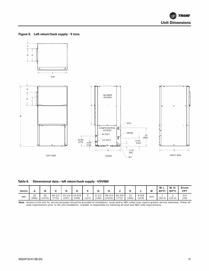
Figure 6. Left return/back supply - 5 tons
H
4-5/8(118)
10-5/8(270)
A
B
C2 1/2"(64)
8 1/4"(210)
19(483)
E
G
L
J
D K
F
BLOWERACCESS
COMP/CONTROLACCESS
TOP
LEFT SIDE FRONT RIGHT SIDE
HI VOLT
LO VOLT
W.O.
W.I.
DRAIN
Table 6. Dimensional data—left return/back supply - VSV060
Units A B C D E F G H J K L MW.I. NPTI
W.O. NPTI
Drain FPT
060 26(660)
62(1575)
30-1/2(775)
13-1/4(337)
13-5/8(346)
5(127)
6-1/2(165)
39-3/4(1010)
30-3/8(772)
13(330)
8-5/8 (219) N/A 1
(25.4)1
(25.4)3/4(19)
Note: Access to the unit for service purposes should be provided at installation. Local and/or NEC codes may require greater service clearance. Check all code requirements prior to the unit installation. Installer is responsible for following all local and NEC code requirements.
WSHP-SVX13B-EN 11

Unit Dimensions
Figure 7. Right return/top supply VSV
C A
3 5/8"3 5/8"(92)(92)
8 3/4"8 3/4"(222)(222)LO VOLTLO VOLT
HI VOLTHI VOLT
W.I.W.I.
DRAINDRAIN
W.O.W.O.
3 5/8"3 5/8"(92)(92)
12"12"(305)(305)
H
B
D
L
F
J M
E
D
K
9 1/2"9 1/2"(241)(241)G
FRONTFRONT RIGHT SIDERIGHT SIDE
TOPTOP
LEFT SIDELEFT SIDE
BLOWER BLOWER ACCESSACCESS
COMP/CONTROL COMP/CONTROL ACCESSACCESS
Table 7. Dimensional data—right return/top supply
Units A B C D E F G H J K L MW.I. NPTI
W.O. NPTI
Drain FPT
024–033 24-1/2(622)
41-7/8(1064)
26-1/2(673)
18(457)
3-1/4(83)
5-3/4(146)
9-1/2(241)
19(483)
23(584)
10-1/2(267)
13-1/2(343)
3/16(5)
3/4(19)
3/4(19)
3/4(19)
042–050 26-1/2(673)
46-7/8(1191)
30-1/2(775)
18(457)
4-1/4(108)
2(51)
9-1/2(241)
29(737)
27-7/8(708)
13-7/8(352)
11-3/8 (289)
1/2(13)
1(25.4)
1(25.4)
3/4(19)
Note: Access to the unit for service purposes should be provided at installation. Local and/or NEC codes may require greater service clearance. Check all code requirements prior to the unit installation. Installer is responsible for following all local and NEC code requirements.
12 WSHP-SVX13B-EN

Unit Dimensions
Figure 8. Right return/top supply - 5 tons
H
4-5/8(118)
10-5/8(270)
A
B
C2 1/2"(64)
8 1/4"(210)
19(483)
J
L
K
F
D
G E
BLOWERACCESS
COMP/CONTROLACCESS
TOP
LEFT SIDE FRONT RIGHT SIDE
HI VOLT
LO VOLT
W.O.
W.I.
DRAIN
Table 8. Dimensional data—right return/top supply - VSV060
Units A B C D E F G H J K L MW.I. NPTI
W.O. NPTI
Drain FPT
060 26(660)
62(1575)
30-1/2(775)
13-1/4(337)
13-5/8(346)
5(127)
7-7/8(200)
39-3/4(1010)
30-3/8(772)
13(330)
8-5/8 (219) N/A 1
(25.4)1
(25.4)3/4(19)
Note: Access to the unit for service purposes should be provided at installation. Local and/or NEC codes may require greater service clearance. Check all code requirements prior to the unit installation. Installer is responsible for following all local and NEC code requirements.
WSHP-SVX13B-EN 13

Unit Dimensions
Figure 9. Right return/back supply VSV
LO VOLTLO VOLT
HI VOLTHI VOLT
8 3/4"8 3/4"(222)(222)
3 5/8"3 5/8"(92)(92)
C
DRAINDRAIN
W.I.W.I.
W.O.W.O.
12"12"(305)(305)
3 5/8"3 5/8"(92)(92)
A
H
D
E
J M
D
F
B
9 1/2"9 1/2"(241)(241)G
BLOWER BLOWER ACCESSACCESS
COMP/CONTROL COMP/CONTROL ACCESSACCESS
LEFT SIDELEFT SIDE FRONTFRONT RIGHT SIDERIGHT SIDE
TOPTOP
Table 9. Dimensional data—right return/back supply
Units A B C D E F G H J K L MW.I. NPTI
W.O. NPTI
Drain FPT
024–033 24-1/2(622)
41-7/8(1064)
26-1/2(673)
18(457)
3-1/4(83)
1-7/8(48)
9-1/2(241)
19(483)
23(584)
10-1/2(267)
13-1/2(343)
3/16(5)
3/4(19)
3/4(19)
3/4(19)
042–050 26-1/2(673)
46-7/8(1191)
30-1/2(775)
18(457)
4-1/4(108)
2(51)
9-1/2(241)
29(737)
27-7/8(708)
13-7/8(352)
11-3/8 (289)
1/2(13)
1(25.4)
1(25.4)
3/4(19)
Note: Access to the unit for service purposes should be provided at installation. Local and/or NEC codes may require greater service clearance. Check all code requirements prior to the unit installation. Installer is responsible for following all local and NEC code requirements.
14 WSHP-SVX13B-EN

Unit Dimensions
Figure 10. Right return/back supply - 5 tons
H
4-5/8(118)
10-5/8(270)
A
B
C2 1/2"(64)
8 1/4"(210)
19(483)
J
D
F
E
G
K
LBLOWERACCESS
COMP/CONTROLACCESS
TOP
LEFT SIDE FRONT RIGHT SIDE
HI VOLT
LO VOLT
W.O.
W.I.
DRAIN
Table 10. Dimensional data—right return/back supply - VSV060
Units A B C D E F G H J K L MW.I. NPTI
W.O. NPTI
Drain FPT
060 26(660)
62(1575)
30-1/2(775)
13-1/4(337)
13-5/8(346)
4(102)
1-1/2(38)
39-3/4(1010)
30-3/8(772)
13(330)
8-5/8 (219) N/A 1
(25.4)1
(25.4)3/4(19)
Note: Access to the unit for service purposes should be provided at installation. Local and/or NEC codes may require greater service clearance. Check all code requirements prior to the unit installation. Installer is responsible for following all local and NEC code requirements.
WSHP-SVX13B-EN 15

Unit Dimensions
Figure 11. Left return/back supply VSH
[102]4 2-1/4
[57]3-1/2[89]
F H
M
1-5/8[41]
CG
J
7/8[22]
2-1/2[64]
E
L K
23-3/4[603]
1-1/8[29]
1-1/8[29]
21-1/4[540]
A
B
D
1-7/8[48]
1/2[13]
18-7/8[479]
10[254]
HI VOLT
LO VOLT
L(W.O.)
FRONTLEFT SIDE
REFRIGANDCONTROLACCESS
M(W.I.)
DRAIN3/4" (19) NPTI
BACK
TOP
F X GOPENING
BLOWERACCESSPANEL
RIGHT SIDE
Table 11. Dimensional data— left return/back supply
Units A B C D E F x G H J K L MW.I. NPTI
W.O. NPTI
Drain FPT
024–033 60-1/4(1530)
26(660)
21-3/8(543)
24(610)
22(559)
13-1/4 x 13-5/8(337) x (346)
7-3/4(197)
1-1/2(38)
32-1/2(826)
1-1/4(32)
18-3/8(467)
3/4(19)
3/4(19)
3/4(19)
042–060 81-1/4(2064)
26(660)
21-3/8(543)
25-1/2(641)
22(559)
13-1/4 x 13-5/8(337) x (346)
7-5/8(194)
2-1/8(54)
52(1321)
1-1/4(32)
18-3/8(467)
1(25.4)
1(25.4)
3/4(19)
Note: Access to the unit for service purposes should be provided at installation. Local and/or NEC codes may require greater service clearance. Check all code requirements prior to the unit installation. Installer is responsible for following all local and NEC code requirements.
16 WSHP-SVX13B-EN

Unit Dimensions
Figure 12. Left return/right supply VSH
23-3/4[603]
1-1/8[29]
L K
1-1/8[29]
A
B
C E
D
1-7/8[48]
2-1/4[57]
4[102]
F H
G
J
M
1-5/8[41]3-1/2
[89]
21-1/4[540]
2-1/2[64]
1/2[13]
18-7/8[479]
10[254]
TOP
HI VOLT
LO VOLT
L(W.O.)
REFRIGANDCONTROLACCESS
M(W.I.)
FRONTLEFT SIDEBACK
DRAIN3/4" (19) NPTI
BLOWERACCESSPANEL
F X GOPENING
RIGHT SIDE
Table 12. Dimensional data— left return/right supply
Units A B C D E F x G H J K L MW.I. NPTI
W.O. NPTI
Drain FPT
024–033 60-1/4(1530)
26(660)
21-3/8(543)
24(610)
22(559)
13-1/4 x 13-5/8(337) x (346)
4-3/4(121)
6-1/4(159)
32-1/2(826)
1-1/4(32)
18-3/8(467)
3/4(19)
3/4(19)
3/4(19)
042–060 81-1/4(2064)
26(660)
21-3/8(543)
25-1/2(641)
22(559)
13-1/4 x 13-5/8(337) x (346)
7-3/4(121)
6-1/4(159)
52(1321)
1-1/4(32)
18-3/8(467)
1(25.4)
1(25.4)
3/4(19)
Note: Access to the unit for service purposes should be provided at installation. Local and/or NEC codes may require greater service clearance. Check all code requirements prior to the unit installation. Installer is responsible for following all local and NEC code requirements.
WSHP-SVX13B-EN 17

Unit Dimensions
Figure 13. Right return/back supply VSH
B
L K
1-1/8[29]
21-1/4[540]
A
1-1/8[29]
23-3/4[603]
2-1/4[57]
4[102] 2-1/2
[64]7/8[22]
C E
F
M
1-5/8[41]
H
3-1/2[89]
1/2[13]
G
J
D
1.875[47,6] 10
[254]
18-7/8[479]HI VOLT
LO VOLT
L(W.O.)
REFRIGANDCONTROLACCESS
M(W.I.)
FRONT
BLOWERACCESSPANEL
LEFT SIDE
DRAIN3/4" (19) NPTI
F X GOPENING
BACK
TOP
RIGHT SIDE
Table 13. Dimensional data — right return/back supply
Units A B C D E F x G H J K L MW.I. NPTI
W.O. NPTI
Drain FPT
024–033 60-1/4(1530)
26(660)
21-3/8(543)
24(610)
22(559)
13-1/4 x 13-5/8(337) x (346)
5-1/4(133)
6-1/4(159)
32-1/2(826)
1-1/4(32)
18-3/8(467)
3/4(19)
3/4(19)
3/4(19)
042–060 81-1/4(2064)
26(660)
21-3/8(543)
25-1/2(641)
22(559)
13-1/4 x 13-5/8(337) x (346)
5-1/8(130)
6-1/4(159)
52(1321)
1-1/4(32)
18-3/8(467)
1(25.4)
1(25.4)
3/4(19)
Note: Access to the unit for service purposes should be provided at installation. Local and/or NEC codes may require greater service clearance. Check all code requirements prior to the unit installation. Installer is responsible for following all local and NEC code requirements.
18 WSHP-SVX13B-EN

Unit Dimensions
Figure 14. Right return/left supply VSH
L K
B
1-1/8[29]
23-3/4[603]
21-1/4[540]
1-1/8[29]
A
C E
2-1/4[57]
4[102]
M
1-5/8[41]
D
1-7/8[48]
H F
J
G
3-1/2[89]
1/2[13] 7/8
[22]2-1/2[64]
10[254]
18-7/8[479]
TOP
REFRIGANDCONTROLACCESS
HI VOLT
LO VOLT
L(W.O.)
M(W.I.)
F X GOPENING
FRONTLEFT SIDEBACK
BLOWERACCESSPANEL
RIGHT SIDE
Table 14. Dimensional data — right return/left supply
Units A B C D E F x G H J K L MW.I. NPTI
W.O. NPTI
Drain FPT
024–033 60-1/4(1530)
26(660)
21-3/8(543)
24(610)
22(559)
13-1/4 x 13-5/8(337) x (346)
4-7/8(124)
1-1/2(38)
32-1/2(826)
1-1/4(32)
18-3/8(467)
3/4(19)
3/4(19)
3/4(19)
042–060 81-1/4(2064)
26(660)
21-3/8(543)
25-1/2(641)
22(559)
13-1/4 x 13-5/8(337) x (346)
4-3/4(121)
1-1/2(38)
52(1321)
1-1/4(32)
18-3/8(467)
1(25.4)
1(25.4)
3/4(19)
Note: Access to the unit for service purposes should be provided at installation. Local and/or NEC codes may require greater service clearance. Check all code requirements prior to the unit installation. Installer is responsible for following all local and NEC code requirements.
WSHP-SVX13B-EN 19

20W
SH
P-SV
X13B
-EN
Un
itFan
Perfo
rman
ce
Unit Fan PerformanceTable 15. Blower performance – VSH
Model External static pressure (inches of water)0.5 0.55 0.6
RPM kW RPM kW RPM
6 715 0.145 739 0.155 762
4 720 0.154 745 0.163 768
2 725 0.162 750 0.172 774
0 730 0.171 755 0.181 779
8 734 0.180 760 0.191 785
7 739 0.189 765 0.200 790
0.5 0.55 0.6
RPM kW RPM kW RPM
8 774 0.220 799 0.232 824
1 780 0.233 806 0.246 831
4 787 0.247 813 0.260 839
8 793 0.262 819 0.276 846
4 800 0.278 826 0.292 853
0 808 0.295 833 0.309 860
0.5 0.55 0.6
RPM kW RPM kW RPM
6 749 0.270 771 0.284 792
9 762 0.294 783 0.309 804
2 779 0.328 800 0.344 821
0 792 0.356 814 0.373 834
9 806 0.386 828 0.403 848
1 825 0.429 846 0.448 866
0.5 0.55 0.6
RPM kW RPM kW RPM
6 749 0.270 771 0.284 792
9 762 0.294 783 0.309 804
2 779 0.328 800 0.344 821
0 792 0.356 814 0.373 834
9 806 0.386 828 0.403 848
0 866 0.562 886 0.584 906
VSH024
CFM0 0.05 0.1 0.15 0.2 0.25 0.3 0.35 0.4 0.45
kW RPM kW RPM kW RPM kW RPM kW RPM kW RPM kW RPM kW RPM kW RPM kW RPM kW
796 0.040 300 0.050 362 0.060 419 0.070 470 0.080 516 0.090 557 0.099 595 0.109 629 0.118 660 0.127 689 0.13
840 0.042 311 0.053 372 0.064 427 0.074 477 0.085 523 0.095 564 0.105 601 0.115 634 0.125 665 0.134 693 0.14
885 0.045 323 0.057 382 0.068 436 0.079 485 0.090 529 0.100 570 0.111 606 0.121 640 0.131 670 0.142 698 0.15
930 0.048 334 0.060 392 0.072 445 0.083 493 0.095 536 0.106 576 0.117 612 0.128 645 0.139 675 0.149 703 0.16
974 0.052 346 0.064 403 0.076 454 0.088 501 0.100 544 0.112 582 0.123 618 0.135 650 0.146 680 0.157 708 0.16
1019 0.056 359 0.069 414 0.081 464 0.094 509 0.106 551 0.118 589 0.130 623 0.142 655 0.154 685 0.166 713 0.17
VSH033
CFM0 0.05 0.1 0.15 0.2 0.25 0.3 0.35 0.4 0.45
kW RPM kW RPM kW RPM kW RPM kW RPM kW RPM kW RPM kW RPM kW RPM kW RPM kW
1014 0.084 397 0.097 451 0.110 501 0.123 546 0.135 587 0.148 624 0.160 658 0.172 690 0.184 719 0.196 747 0.20
1076 0.090 415 0.104 467 0.118 515 0.131 558 0.144 597 0.157 633 0.170 667 0.183 697 0.195 726 0.208 754 0.22
1138 0.098 433 0.112 483 0.126 529 0.140 570 0.154 608 0.168 643 0.181 675 0.195 705 0.208 733 0.221 760 0.23
1200 0.106 452 0.121 500 0.136 544 0.151 583 0.165 620 0.179 653 0.193 684 0.207 713 0.221 741 0.235 767 0.24
1262 0.116 472 0.132 518 0.147 559 0.162 597 0.177 632 0.192 664 0.206 693 0.221 722 0.235 749 0.249 775 0.26
1324 0.127 493 0.143 536 0.159 575 0.175 611 0.190 644 0.205 675 0.220 703 0.235 731 0.250 757 0.265 782 0.28
VSH042
CFM0 0.05 0.1 0.15 0.2 0.25 0.3 0.35 0.4 0.45
kW RPM kW RPM kW RPM kW RPM kW RPM kW RPM kW RPM kW RPM kW RPM kW RPM kW
1414 0.102 451 0.117 488 0.133 523 0.149 556 0.164 588 0.180 619 0.196 647 0.211 675 0.226 701 0.241 726 0.25
1485 0.117 471 0.133 507 0.150 541 0.166 573 0.183 604 0.199 633 0.216 662 0.232 689 0.248 714 0.264 738 0.27
1579 0.140 499 0.157 532 0.175 565 0.192 596 0.210 626 0.228 654 0.245 681 0.262 708 0.279 732 0.296 756 0.31
1650 0.158 519 0.177 552 0.195 583 0.214 613 0.232 642 0.251 670 0.269 697 0.287 722 0.305 747 0.322 770 0.34
1721 0.179 539 0.198 571 0.217 601 0.237 631 0.256 659 0.276 686 0.295 712 0.314 737 0.332 761 0.351 784 0.36
1815 0.208 566 0.229 596 0.250 625 0.270 654 0.291 681 0.312 707 0.332 733 0.352 757 0.372 781 0.391 803 0.41
VSH050
CFM0 0.05 0.1 0.15 0.2 0.25 0.3 0.35 0.4 0.45
kW RPM kW RPM kW RPM kW RPM kW RPM kW RPM kW RPM kW RPM kW RPM kW RPM kW
1414 0.102 451 0.117 488 0.133 523 0.149 556 0.164 588 0.180 619 0.196 647 0.211 675 0.226 701 0.241 726 0.25
1485 0.117 471 0.133 507 0.150 541 0.166 573 0.183 604 0.199 633 0.216 662 0.232 689 0.248 714 0.264 738 0.27
1579 0.140 499 0.157 532 0.175 565 0.192 596 0.210 626 0.228 654 0.245 681 0.262 708 0.279 732 0.296 756 0.31
1650 0.158 519 0.177 552 0.195 583 0.214 613 0.232 642 0.251 670 0.269 697 0.287 722 0.305 747 0.322 770 0.34
1721 0.179 539 0.198 571 0.217 601 0.237 631 0.256 659 0.276 686 0.295 712 0.314 737 0.332 761 0.351 784 0.36
2077 0.301 624 0.326 652 0.350 679 0.374 705 0.399 730 0.423 754 0.447 778 0.471 801 0.494 823 0.517 845 0.54

WS
HP-S
VX
13B-E
N21
Un
itFan
Perfo
rma
nce
CFM0 0.05 0.1 0.15 0.2 0.25 0.3 0.35 0.4 0.45 0.5 0.55 0.6
kW RPM kW RPM kW RPM kW RPM kW RPM kW RPM kW RPM kW RPM kW RPM kW RPM kW RPM kW RPM kW RPM
2 833 0.439 854 0.457 875
0 854 0.488 874 0.507 895
3 874 0.542 894 0.562 915
0 895 0.601 915 0.623 935
4 916 0.666 935 0.689 956
2 936 0.736 955 0.761 976
Table 15. Blower performance – VSH (continued)
Model External static pressure (inches of water)
0.5 0.55 0.6
RPM kW RPM kW RPM
2 845 0.204 873 0.214 899
0 857 0.222 885 0.234 911
7 868 0.240 896 0.253 923
6 880 0.261 908 0.274 935
6 892 0.281 920 0.296 947
0.5 0.55 0.6
RPM kW RPM kW RPM
2 829 0.267 854 0.280 879
8 844 0.293 869 0.308 894
5 858 0.322 883 0.338 908
5 874 0.352 898 0.369 923
6 889 0.385 913 0.403 938
0.5 0.55 0.6
RPM kW RPM kW RPM
1 898 0.480 927 0.509 956
8 916 0.528 944 0.559 974
7 932 0.579 961 0.613 991
9 948 0.633 977 0.668 1007
2 963 0.689 991 0.726 1021
VSH060
1803 0.240 574 0.262 610 0.282 641 0.301 671 0.319 698 0.337 724 0.354 748 0.371 770 0.388 792 0.405 813 0.42
1908 0.275 603 0.298 637 0.319 667 0.340 696 0.360 722 0.379 747 0.397 770 0.416 792 0.434 813 0.452 834 0.47
2014 0.314 631 0.338 664 0.361 693 0.383 721 0.405 746 0.425 770 0.445 792 0.465 814 0.484 834 0.503 855 0.52
2120 0.357 659 0.383 690 0.408 719 0.431 745 0.454 770 0.476 793 0.497 815 0.518 836 0.539 856 0.560 876 0.58
2226 0.405 686 0.432 716 0.458 744 0.483 769 0.508 793 0.531 816 0.554 837 0.577 857 0.599 877 0.621 896 0.64
2332 0.457 711 0.486 741 0.514 768 0.541 793 0.567 816 0.592 838 0.617 859 0.641 879 0.665 898 0.689 917 0.71
Table 16. Blower performance – VSV
Model External static pressure (inches of water)
VSV024
CFM0 0.05 0.1 0.15 0.2 0.25 0.3 0.35 0.4 0.45
kW RPM kW RPM kW RPM kW RPM kW RPM kW RPM kW RPM kW RPM kW RPM kW RPM kW
837 0.070 456 0.079 505 0.090 551 0.101 595 0.114 637 0.127 677 0.140 714 0.153 750 0.167 784 0.180 815 0.19
884 0.081 483 0.090 529 0.101 572 0.113 614 0.126 654 0.140 692 0.154 729 0.168 763 0.182 796 0.196 827 0.21
930 0.092 508 0.102 551 0.113 593 0.125 633 0.139 671 0.153 708 0.168 743 0.183 776 0.198 808 0.213 839 0.22
977 0.105 534 0.115 575 0.127 614 0.140 652 0.154 689 0.168 724 0.184 758 0.200 790 0.215 821 0.231 851 0.24
1023 0.118 559 0.129 597 0.141 635 0.154 671 0.169 706 0.184 739 0.200 772 0.217 804 0.233 834 0.250 864 0.26
VSV033
CFM0 0.05 0.1 0.15 0.2 0.25 0.3 0.35 0.4 0.45
kW RPM kW RPM kW RPM kW RPM kW RPM kW RPM kW RPM kW RPM kW RPM kW RPM kW
1080 0.118 538 0.128 571 0.138 603 0.151 634 0.164 664 0.178 693 0.192 722 0.207 750 0.222 777 0.237 803 0.25
1140 0.137 568 0.147 598 0.158 628 0.171 657 0.184 685 0.199 713 0.214 740 0.230 766 0.246 792 0.262 818 0.27
1200 0.158 596 0.168 624 0.179 652 0.192 679 0.207 705 0.222 731 0.238 757 0.254 783 0.271 808 0.288 833 0.30
1260 0.181 625 0.191 651 0.203 676 0.217 701 0.232 726 0.247 751 0.264 775 0.281 800 0.299 824 0.317 849 0.33
1320 0.206 653 0.217 676 0.229 700 0.243 723 0.259 746 0.275 770 0.292 793 0.310 817 0.329 841 0.348 865 0.36
VSV042
CFM0 0.05 0.1 0.15 0.2 0.25 0.3 0.35 0.4 0.45
kW RPM kW RPM kW RPM kW RPM kW RPM kW RPM kW RPM kW RPM kW RPM kW RPM kW
1485 0.175 553 0.207 599 0.237 641 0.266 680 0.294 716 0.320 750 0.346 782 0.372 812 0.398 841 0.424 870 0.45
1568 0.202 580 0.236 624 0.268 665 0.299 703 0.328 737 0.357 770 0.385 801 0.413 830 0.441 859 0.469 887 0.49
1650 0.231 607 0.267 650 0.301 689 0.334 725 0.366 758 0.396 790 0.426 820 0.456 848 0.486 876 0.516 904 0.54
1733 0.262 634 0.300 674 0.336 711 0.371 746 0.405 778 0.437 808 0.469 837 0.501 865 0.533 893 0.566 920 0.59
1815 0.294 659 0.334 698 0.373 733 0.410 766 0.446 797 0.481 826 0.515 854 0.549 881 0.583 908 0.617 935 0.65

22W
SH
P-SV
X13B
-EN
Un
itFan
Perfo
rman
ce
CFM0 0.05 0.1 0.15 0.2 0.25 0.3 0.35 0.4 0.45 0.5 0.55 0.6
kW RPM kW RPM kW RPM kW RPM kW RPM kW RPM kW RPM kW RPM kW RPM kW RPM kW RPM kW RPM kW RPM
5 960 0.650 990 0.687 1020
9 978 0.717 1007 0.757 1038
7 994 0.788 1023 0.830 1054
9 1009 0.862 1038 0.906 1068
2 1022 0.938 1050 0.986 1081
0.5 0.55 0.6
RPM kW RPM kW RPM
7 821 0.443 845 0.469 870
6 840 0.493 864 0.521 888
0 860 0.549 883 0.578 907
9 881 0.610 903 0.641 926
5 901 0.677 923 0.710 946
6 922 0.750 944 0.784 967
Table 16. Blower performance – VSV (continued)
Model External static pressure (inches of water)
VSV050
1701 0.265 636 0.305 678 0.343 716 0.379 752 0.414 785 0.448 817 0.481 847 0.514 875 0.547 904 0.581 932 0.61
1796 0.304 666 0.346 706 0.387 742t 0.426 776 0.463 808 0.500 838 0.535 867 0.571 895 0.607 922 0.643 950 0.67
1890 0.345 695 0.391 733 0.434 767 0.475 799 0.515 829 0.554 858 0.593 886 0.631 912 0.669 939 0.708 966 0.74
1985 0.390 724 0.438 759 0.483 791 0.528 821 0.570 850 0.612 877 0.653 903 0.694 929 0.735 955 0.777 981 0.81
2079 0.436 751 0.486 783 0.535 814 0.582 842 0.628 868 0.672 894 0.716 919 0.760 944 0.804 969 0.848 995 0.89
VSV060
CFM0 0.05 0.1 0.15 0.2 0.25 0.3 0.35 0.4 0.45
kW RPM kW RPM kW RPM kW RPM kW RPM kW RPM kW RPM kW RPM kW RPM kW RPM kW
1816 0.153 515 0.185 558 0.214 598 0.242 634 0.269 667 0.295 696 0.319 724 0.344 750 0.368 774 0.392 798 0.41
1918 0.185 542 0.218 585 0.249 623 0.279 658 0.308 690 0.335 719 0.362 746 0.388 771 0.414 794 0.440 818 0.46
2019 0.220 570 0.256 612 0.289 649 0.321 683 0.351 714 0.380 742 0.409 768 0.437 792 0.464 815 0.492 838 0.52
2121 0.261 599 0.299 639 0.334 675 0.367 708 0.400 738 0.431 765 0.461 790 0.491 814 0.520 837 0.550 859 0.57
2222 0.308 627 0.347 666 0.384 702 0.420 734 0.454 763 0.487 789 0.519 813 0.550 836 0.582 858 0.613 880 0.64
2324 0.361 656 0.402 694 0.441 728 0.478 759 0.514 787 0.549 813 0.583 837 0.616 859 0.649 880 0.683 901 0.71

Unit Fan Performance
MERV Filter
Table 17. Added pressure drop through MERV filters (inches water column) – VSH
Model No. CFM MERV 8 MERV 13
VSH024
742 0.08 0.09
836 0.09 0.10
930 0.10 0.12
977 0.11 0.12
1024 0.11 0.13
VSH033
952 0.10 0.12
1076 0.12 0.14
1200 0.14 0.16
1262 0.15 0.17
1324 0.21 0.19
VSH042
1324 0.09 0.10
1487 0.10 0.11
1650 0.11 0.13
1731 0.12 0.14
1813 0.13 0.15
VSH050
1517 0.10 0.12
1704 0.12 0.14
1890 0.13 0.16
1983 0.14 0.17
2077 0.15 0.18
VSH060
1890 0.13 0.16
2016 0.14 0.17
2120 0.15 0.18
2225 0.16 0.19
2329 0.17 0.21
Note: Added pressure drop should be considered when utilizing optional 2" MERV 8 and MERV 13 filters.
Table 18. Added pressure drop through MERV filters (inches water column) – VSV
Model No. CFM MERV 8 MERV 13
VSV024
837 0.12 0.14
884 0.13 0.15
930 0.14 0.16
977 0.15 0.17
1023 0.15 0.18
VSV033
1080 0.16 0.20
1140 0.18 0.21
1200 0.19 0.23
1260 0.20 0.24
1320 0.21 0.26
WSHP-SVX13B-EN 23

Unit Fan Performance
VSV042
1485 0.13 0.15
1568 0.14 0.16
1650 0.15 0.17
1733 0.15 0.18
1815 0.16 0.19
VSV050
1701 0.15 0.18
1796 0.16 0.19
1890 0.17 0.21
1985 0.18 0.22
2079 0.19 0.23
VSV060
1900 0.14 0.16
2021 0.15 0.17
2121 0.16 0.19
2221 0.17 0.20
2321 0.18 0.21
Notes: Added pressure drop should be considered when utilizing optional 2" MERV 8 and MERV 13 filters.
Table 18. Added pressure drop through MERV filters (inches water column) – VSV (continued)
Model No. CFM MERV 8 MERV 13
24 WSHP-SVX13B-EN

General Data
Table 19. Cabinet
Model VSH VSH024 VSH033 VSH042 VSH050 VSH060
Unit size
Length (inch) 60.2 60.2 81.2 81.2 81.2
Height (inch) 22.0 22.0 22.0 22.0 22.0
Width (inch) 26.0 26.0 26.0 26.0 26.0
Compressor type Rotary Rotary Scroll Scroll Scroll
Approximate weight With pallet (lb) 381 381 591 591 591
Approximate weight Without pallet (lb) 333 333 524 524 524
Filter sizeInches 16 x 20 x 1 16 x 20 x 1 20 x 25 x 1 20 x 25 x 1 20 x 25 x 1
Inches 20 x 20 x 1 20 x 20 x 1 20 x 30 x 1 20 x 30 x 1 20 x 30 x 1
Water in/out size (NPTI) Inches 3/4 3/4 1 1 1
Condensate size (NPTI) Inches 3/4 3/4 3/4 3/4 3/4
Blower wheel size Direct drive (inch) 11 x 10 11 x 10 11 x 10 11 x 10 11 x 10
Table 20. Air-to-refrigerant coil
Model VSH VSH024 VSH033 VSH042 VSH050 VSH060
Working pressure 650 650 650 650 650
Tubes high 20 20 20 20 20
Tubes deep 3 3 4 4 4
Number of circuits 3 3 5 5 5
Finned volume (H, W, D: inches) 20x31.5x2.6 20x31.5x2.6 20x51x3.464 20x51x3.464 20x51x3.464
Coil surface area (ft2) 4.375 4.375 7.083 7.083 7.083
Fins per inch 12 12 12 12 12
Tube material Copper Copper Copper Copper Copper
Tube OD (inch) 3/8 3/8 3/8 3/8 3/8
Wall thickness (inch) 0.014 0.014 0.014 0.014 0.014
Return bends Copper Copper Copper Copper Copper
Table 21. Water volume
Model VSH VSH024 VSH033 VSH042 VSH050 VSH060
Internal water volume (in3) 142.4 142.4 331.2 331.2 331.2
Internal water volume (ft3) 0.082 0.082 0.192 0.192 0.192
Internal water volume (gal) 0.616 0.616 1.434 1.434 1.434
WSHP-SVX13B-EN 25

General Data
Table 22. Cabinet
Model VSV VSV024 VSV033 VSV042 VSV050 VSV060
Unit size
Length (inch) 26-1/2 26-1/2 30-1/2 30-1/2 30 1/2
Height (inch) 41-7/8 41-7/8 46-7/8 46-7/8 62 1/2
Width (inch) 24-1/2 24-1/2 26-1/2 26-1/2 26
Compressor type Rotary Rotary Scroll Scroll Scroll
Approximate weight With pallet (lb) 334 334 495 495 5111
Approximate weight Without pallet (lb) 309 309 460 460 488
Filter size Actual (inch) 19-7/8 x 24-7/8 19-7/8 x 24-7/8 27-7/8 x 29-7/8 27-7/8 x 29-7/8 20 x 30 Qty 2
Water in/out size (NPTI) Inches 3/4 3/4 1 1 1
Condensate size (NPTI) Inches 3/4 3/4 3/4 3/4 3/4
Blower wheel size Direct drive (inch) 11 x 8 11 x 8 12 x 11 12 x 11 11 x 10
Table 23. Air-to-refrigerant coil
Model VSV VSV024 VSV033 VSV042 VSV50 VSV060
Working pressure 650 650 650 650 650
Tubes high 18 18 24 24 39
Tubes deep 3 3 4 4 4
Number of circuits 4 4 6 6 6
Finned volume (H, W, D: inches) 18 x 21 x 2.6 18 x 21 x 2.6 24 x 25 x 3.5 24 x 25 x 3.5 39x29.25x3.464
Coil surface area (ft2) 2.63 2.63 4.17 4.17 6.97
Fins per inch 12 12 12 12 12
Tube material Copper Copper Copper Copper Copper
Tube OD (inch) 3/8 3/8 3/8 3/8 3/8
Wall thickness (inch) 0.014 0.014 0.014 0.014 0.014
Return bends Copper Copper Copper Copper Copper
Table 24. Water volume
Model VSV VSV024 VSV033 VSV042 VSV050 VSV060
Internal water volume (in3) 212 212 414 414 414
Internal water volume (ft3) 0.123 0.123 0.24 0.24 0.24
Internal water volume (gal) 0.918 0.918 1.792 1.792 1.792
26 WSHP-SVX13B-EN

General Data
Table 25. ISO ratings (VSH)(a)
Model Load
ing
Rat
ed w
ater
flo
w (
GP
M)
Rat
ed A
ir F
low
(C
FM)
Coo
ling
cap
acit
y W
LHP
(B
TUH
)
EER
WLH
P
Hea
tin
g c
apac
ity
WLH
P (
BTU
H)
CO
P W
LHP
Coo
ling
cap
acit
y G
WH
P (
BTU
H)
EER
GW
HP
Hea
tin
g c
apac
ity
GW
HP
(B
TUH
)
CO
P G
WH
P
Coo
ling
cap
acit
y G
LHP
(B
TUH
)
EER
GLH
P
Hea
tin
g c
apac
ity
GLH
P (
BTU
H)
CO
P G
LHP
VSH024 Full 6.2 930 25,100 18.30 30,300 6.44 28,400 31.76 24,300 5.33 26,200 21.82 18,500 4.35
VSH024 Partial 6.2 625 13,800 23.67 15,900 8.64 15,500 48.23 12,400 6.37 15,000 36.43 10,300 4.99
VSH033 Full 8.6 1200 33,800 15.79 40,200 5.85 37,900 25.01 32,300 4.98 35,300 18.51 24,700 4.10
VSH033 Partial 8.6 720 17,600 21.96 21,000 7.71 19,700 41.82 16,600 5.94 18,900 32.23 14,300 4.96
VSH042 Full 10.5 1650 42,600 18.60 51,800 6.70 47,300 30.90 42,000 5.60 44,600 22.00 31,500 4.50
VSH042 Partial 10.5 1065 24,100 23.26 29,800 8.21 27,200 48.49 23,500 6.45 26,100 35.38 18,800 5.39
VSH050 Full 12.7 1890 50,200 16.50 64,400 5.80 56,200 26.00 52,500 5.10 52,400 19.30 40,100 4.20
VSH050 Partial 12.7 1200 28,400 22.29 36,100 7.52 32,400 42.02 29,100 6.16 31,000 33.67 24,000 5.28
VSH060 Full 15.6 2100 60,700 14.80 81,600 5.30 67,300 22.80 66,800 4.70 63,200 17.00 50,400 3.80
VSH060 Partial 15.6 1323 36,400 20.56 46,500 6.77 40,900 37.58 37,400 5.72 39,100 31.43 31,300 5.06
(a) Note: Rated in accordance with ISO Standard 13256-1 - 1 1998, Water-to-Air and Brine-to-Air Heat Pumps. Certified conditions are 80.6°F DB/66.2°F WB EAT in cooling and 68°F DB/59°F WB EAT in heating. Entering liquid temperature in cooling is 86°F for Water Loop, 77°F for Ground Loop (full load), 68°F for Ground Loop (part load), and 59°F for Ground Water. Entering liquid temperature in heating is 68°F for Water Loop, 32°F for Ground Loop (full load), 41°F for Ground Loop (part load), and 50°F for Ground Water.
Table 26. ISO ratings (VSV)(a)
Model Load
ing
Rat
ed w
ater
flo
w (
GP
M)
Rat
ed A
ir F
low
(C
FM)
Coo
ling
cap
acit
y W
LHP
(B
TUH
)
EER
WLH
P
Hea
tin
g c
apac
ity
WLH
P (
BTU
H)
CO
P W
LHP
Coo
ling
cap
acit
y G
WH
P (
BTU
H)
EER
GW
HP
Hea
tin
g c
apac
ity
GW
HP
(B
TUH
)
CO
P G
WH
P
Coo
ling
cap
acit
y G
LHP
(B
TUH
)
EER
GLH
P
Hea
tin
g c
apac
ity
GLH
P (
BTU
H)
CO
P G
LHP
VSV024 Full 6.2 930 24,600 18.44 30,300 6.10 27,800 33.24 24,400 5.20 25,900 22.32 18,400 4.17
VSV024 Partial 6.2 625 13,100 22.58 15,900 7.62 15,000 48.48 12,100 6.13 14,300 35.31 9,900 4.81
VSV033 Full 8.3 1200 32,900 15.47 40,400 5.46 36,600 24.67 32,400 4.77 34,300 18.08 24,500 3.86
VSV033 Partial 8.3 720 17,100 20.81 21,500 6.96 19,400 40.79 16,800 5.59 18,500 31.59 14,100 4.60
VSV042 Full 10.9 1650 44,100 18.25 54,700 5.95 50,100 32.46 43,600 5.08 46,200 22.03 31,900 3.98
VSV042 Partial 10.9 1200 25,500 24.17 29,400 7.50 28,700 51.26 22,700 5.85 26,900 40.50 17,800 4.59
VSV050 Full 13.0 1890 51,200 15.72 68,800 5.32 57,800 26.19 54,600 4.58 54,100 18.76 41,400 3.75
VSV050 Partial 13.0 1200 29,900 22.08 36,800 6.88 33,500 42.46 28,500 5.50 32,800 34.00 23,400 4.62
VSV060 Full 15.6 2100 61,800 15.60 81,200 5.50 70,400 25.40 65,400 4.80 64,600 18.30 50,000 4.00
VSV060 Partial 15.6 1323 35,900 21.28 46,300 7.30 41,300 41.38 36,200 5.91 39,600 32.88 30,400 5.29
WSHP-SVX13B-EN 27

Installation
General Installation Checks
The checklist below is a summary of the steps required tosuccessfully install a commercial unit.This checklist isintended to acquaint the installing personnel with what isrequired in the installation process. It does not replace thedetailed instructions called out in the applicable sectionsof this manual.
1. Remove packaging and inspect the unit. Check the unitfor shipping damage and material shortage; file afreight claim and notify appropriate salesrepresentation.
Note: The VSV units have been tied to the skid by (2)shipping bolts.The removal of these bolts willrequire a 3/8 inch (9.7 mm) ratchet with a ½ inch(12.7 mm) socket.
Note: The VSH units have been secured to the skid byshipping brackets.The removal requires a ½”socket with a 3/8” ratchet.
2. Verify the correct model, options and voltage from theunit nameplate.
3. Pull out all field attached parts (i.e. filter rack, ductcollar, filter and mounting screws) from the unitpackaging for field mounting.
4. Verify the installation location of the unit will providethe required clearance for proper operation.
5. Remove refrigeration access panel and inspect theunit. Be certain the refrigerant tubing has clearancefrom adjacent parts.
Note: Removal of compressor shipping brackets isrequired on models VSHE 042, 050, 060 &VSVE060.The removal of the shipping bracketsrequires a 1/2” socket with a 3/8” ratchet. A bracketis provided on the right and left side of thecompressor and requires the removal of 4 bolts perbracket.
6. Fabricate and install duct work.
7. Install and connect a condensate drain line and trap tothe drain connection.
Main Electrical
8. Verify the power supply complies with the unitnameplate specifications.
9. Inspect all control panel components; tighten anyloose connections.
10. Connect properly sized and protected power supplywiring to a field-supplied/installed disconnect switchand to the power block.
11. Install proper grounding wires to an earth ground.VSV/VSH 460V units require a neutral (a four wiresystem).
Note: All field-installed wiring must comply with NECand applicable local codes.
Low Voltage Wiring (AC) Requirements
12. Install the zone sensor.
13. Connect properly sized control wiring to the propertermination points between the zone sensor and theunit control panel.
Filter Installation
14. Each unit ships with 1 inch (25.4 mm) or 2 inch (50.8mm) disposable, MERV 8 or MERV 13 filter(s).The filteris factory installed.
Note: Do not operate the unit without filters.
Supply-Air Ductwork
Install the 1 inch (25.4 mm) supply-air duct flange to theunit with the (8) 5/16 inch (7.94 mm) factory supplied headscrews.The duct collar assembly for each unit is shippedwith the unit in the same box where the IOM manual islocated.
When attaching the field ductwork to the unit, provide awatertight flexible connector at the unit to preventoperating sounds from transmitting through theductwork. See Figure 15, p. 29.
Elbows with turning vanes or splitters are recommendedto minimize air noise due to turbulence and to reduce staticpressure.
WARNING
Hazardous Voltage!
Disconnect all electric power, including remotedisconnects before servicing. Follow proper lockout/tagout procedures to ensure the power can not beinadvertently energized. Failure to disconnect powerbefore servicing could result in death or serious injury.
WARNING
Proper Field Wiring and Grounding
Required!
All field wiring MUST be performed by qualifiedpersonnel. Improperly installed and grounded fieldwiring poses FIRE and ELECTROCUTION hazards.Toavoid these hazards, you MUST follow requirements forfield wiring installation and grounding as described inNEC and your local/state electrical codes. Failure tofollow codes could result in death or serious injury.
28 WSHP-SVX13B-EN

Installation
Return-Air Ductwork
The equipment factory ships with the filter rail and filter(s)installed for free return.
When a ducted return is required, a ducted filter rack orducted panel must be installed on the unit.When attachingthe field ductwork to the unit, provide a water tight flexibleconnector at the unit to prevent operating sounds fromtransmitting through the ductwork. See Figure 16, p. 29.
Elbows with turning vanes or splitters are recommendedto minimize air noise due to turbulence and to reduce staticpressure.
Note: Installation of a return-air ducted panel or ductedfilter rack require the removal of the filter rails.
Return Air Ducted Panel
Ducted panel
The return-air arrangement may be easily converted froma free return-air system to a ducted return-air system withthe addition of a return-air ducted panel. By replacing thefilter rail with the return-air panel, a complete seal from theduct to the unit is possible.The 1-inch duct panel facilitatesease of field connection to the mechanical system.Thisaccessory is typically used when the return air filter is
placed up stream of the unit or placed within a fieldprovided filter rack assembly.
Ducted Filter Rack
When it is necessary to have filter access at the unit in aducted return, a ducted filter rack is available.This optionallows access to the filter at the unit. Vertical unit filterracks are available in right or left access configurations.Horizontal units are available in side or bottom accessconfigurations.
Figure 15. Flexible supply-air connector (field provided)
Figure 16. Flexible return-air connector (field provided)
SUPPLY-AIR
RETURN
AIR
DUCT COLLAR
(FACTORY PROVIDED)
RETURN-AIR BOOT
(FIELD PROVIDED)
DUCT COLLAR
Figure 17. Ducted panel
Table 27. Return air ducted panel (horizontal only)
Unit A B Part Number
024, 033 31.5” 19.2” 4476 0334 0100
042, 050, 060 51.1” 19.2” 4476 0335 0100
Figure 18. Ducted filter rack
Table 28. Ducted filter opening size
Unit A B C
VSH 024, 033 35.8” 20.2” 5.5”
VSH 042, 050, 060 54.8” 20.2” 5.5”
A
B
WSHP-SVX13B-EN 29
Installation
Sound Attenuation Pad
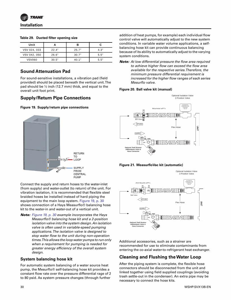
For sound-sensitive installations, a vibration pad (fieldprovided) should be placed beneath the vertical unit.Thepad should be ½ inch (12.7 mm) thick, and equal to theoverall unit foot print.
Supply/Return Pipe Connections
Connect the supply and return hoses to the water-inlet(from supply) and water-outlet (to return) of the unit. Forvibration isolation, it is recommended that flexible steelbraided hoses be installed instead of hard piping theequipment to the main loop system. Figure 19, p. 30shows connection of a Hays Measurflo® balancing hosekit to the water-in and water-out of a vertical unit.
Note: Figure 19, p. 30 example incorporates the HaysMeasurflo® balancing hose kit and a 2-positionisolation valve into the system design.An isolationvalve is often used in variable-speed pumpingapplications.The isolation valve is designed tostop water flow to the unit during non-operationtimes.This allows the loop water pumps to run onlywhen a requirement for pumping is needed forgreater energy efficiency of the overall systemdesign.
System balancing hose kit
For automatic system balancing of a water source heatpump, the Mesurflo® self-balancing hose kit provides aconstant flow rate over the pressure differential rage of 2to 80 psid. As system pressure changes (through further
addition of heat pumps, for example) each individual flowcontrol valve will automatically adjust to the new systemconditions. In variable water volume applications, a self-balancing hose kit can provide continuous balancingbecause of its ability to automatically adjust to the varyingsystem conditions.
Note: At low differential pressure the flow area requiredto achieve higher flow can exceed the flow areaavailable for the respective series.Therefore, theminimum pressure differential requirement isincreased for the higher flow ranges of each seriesMesurflo valve.
Additional accessories, such as a strainer arerecommended for use to eliminate contaminants fromentering the co-axial water-to-refrigerant heat exchanger.
Cleaning and Flushing the Water Loop
After the piping system is complete, the flexible hoseconnectors should be disconnected from the unit andlinked together using field supplied couplings (avoidingtrash settle-out in the condenser). An extra pipe may benecessary to connect the hose kits.
Table 29. Ducted filter opening size
Unit A B C
VSV 024, 033 22.4” 25.7” 4.3”
VSV 042, 050 26.6” 30.7” 5.5”
VSV060 30.5” 40.1” 5.5”
Figure 19. Supply/return pipe connections
Figure 20. Ball valve kit (manual)
Figure 21. MeasurfloVac kit (automatic)
Flex Hose
Mesurmeter w/PT’s
Optional Yball Strainer w/Blowdown Valve &
Hose Connector
PTFLOW
Ball Valve
Optional Isolation Valve2-Position Valve
AUTOMATICTEMPERATURE
CONTROL VALVE
Flex Hose
Optional Yball Strainer w/Blowdown Valve &
Hose Connector
PTFLOW
Ball Valve
Optional Isolation Valve2-Position Valve
2510 Mesurflo w/PT’sAUTOMATIC
TEMPERATURECONTROL
VALVE
30 WSHP-SVX13B-EN

Installation
1. Water circulation system should be filled with cleanwater using the water make up connections.
Note: Air vents should be open during filling.
2. With the air vents closed, start the circulating pumpand then crack the air vents to bleed off the trapped air,assuring circulation through all components of thesystem.
Note: Make up water must be available to the system toreplace the volume formerly occupied by the airthat is bled off.
3. With the air vented and the water circulating, the entiresystem should be checked for leaks with repairs madeas required.
4. Operate the supplementary heat system (boiler) ifapplicable making checks per manufacturer’sinstructions. During this operation, visual checksshould be made for leaks that may have occurred dueto increased heat. Repair as required.
5. Open the system at the lowest point for the initial blowdown (making sure the make up water is equal to thewater being dumped). Continue blow down until thewater leaving the drain runs clear, but not less than 2hours.
6. Shut down pumps and supplementary heat system (ifapplicable). Reconnect the hoses placing the water-to-refrigerant heat exchanger in the water circulatingsystem.
Note: Vents should be open when the pumps andsupplementary heat system are shut down.
Field Installed Power Wiring
Verify that the power supply available is compatible withthe unit’s nameplate. Use only copper conductors toconnect the power supply to the unit.
Main Unit Power Wiring
A field supplied disconnect switch must be installed at ornear the unit in accordance with the National Electric Code(NEC latest edition).
Location of the applicable electric service entrance forHIGH (line voltage) may be found in the Dimensionssection of this manual.
The high-voltage connection is made at the power blockinside the unit control box. Refer to the customerconnection diagram that is shipped with the unit forspecific termination points.
Provide proper grounding for the unit in accordance withthe local and national codes.
Control PowerTransformer
The 24V control power transformer is to be used only withthe accessories called out in this manual. All variable-speed WSHP units include a 75 VA control transformerequipped with a circuit breaker. If a circuit breaker trips,turn OFF all power to the unit before attempting to reset it.
WARNING
Proper Field Wiring and Grounding
Required!
All field wiring MUST be performed by qualifiedpersonnel. Improperly installed and grounded fieldwiring poses FIRE and ELECTROCUTION hazards.Toavoid these hazards, you MUST follow requirements forfield wiring installation and grounding as described inNEC and your local/state electrical codes. Failure tofollow codes could result in death or serious injury.
WARNING
Live Electrical Components!
During installation, testing, servicing andtroubleshooting of this product, it may be necessary towork with live electrical components. Have a qualifiedlicensed electrician or other individual who has beenproperly trained in handling live electrical componentsperform these tasks. Failure to follow all electricalsafety precautions when exposed to live electricalcomponents could result in death or serious injury.
NOTICE:
Use Copper Conductors Only!
Unit terminals are not designed to accept other typesof conductors. Failure to use copper conductors mayresult in equipment damage.
WARNING
Proper Field Wiring and Grounding
Required!
All field wiring MUST be performed by qualifiedpersonnel. Improperly installed and grounded fieldwiring poses FIRE and ELECTROCUTION hazards.Toavoid these hazards, you MUST follow requirements forfield wiring installation and grounding as described inNEC and your local/state electrical codes. Failure tofollow codes could result in death or serious injury.
WSHP-SVX13B-EN 31

Installation
Sensor Location
Location of the zone sensor is an important element ofeffective room control.
Areas where the zone sensor should not be locatedinclude:
• Behind doors or corners
• Near hot or cold air ducts
• Near radiant heat (this is heat emitted from appliancesor the sun)
• Near concealed pipes or chimneys
• On outside walls or other non conditioned surfaces
In air-flows from adjacent zones or other units.ControlsUsing 24 VAC
Before installing any wire, refer to the electrical accesslocations in “Unit Dimensions,” p. 7 of this manual.
Ensure that the AC control wiring between the controlsand the unit’s termination point does not exceed three (3)ohms/conductor for the length of the run.
Note: Resistance in excess of 3 Ω per conductor maycause component failure due to insufficient ACvoltage supply.
Check all loads and conductors for grounds, shorts, andmis-wiring.
Use copper conductors unless otherwise specified.
Do not run the AC low voltage wiring in the same conduitwith the high voltage power wiring.
WARNING
Hazardous Voltage!
Disconnect all electric power, including remotedisconnects before servicing. Follow proper lockout/tagout procedures to ensure the power can not beinadvertently energized. Failure to disconnect powerbefore servicing could result in death or serious injury.
Figure 22. Sensor location
5 Fe
et
YESNO
NO
NOO
Table 30. 24V AC conductors
Distance from unit to control Recommended wire size
0-460 feet 18 gauge
461-732 feet 16 gauge
733-1000 feet 14 gauge
32 WSHP-SVX13B-EN

WSHP-SVX13B-EN 33
Electrical Data
WARNING
Rotating Components!
Disconnect all electric power, including remote disconnects before servicing. Follow proper lockout/tagoutprocedures to ensure the power can not be inadvertently energized. Failure to disconnect power before servicingcould result in death or serious injury.
Table 31. VSH electrical data
Model No. Unit VoltsTotal Unit
FLAComp RLA
(ea)No. of
CompressorsBlower
Motor FLABlower
Motor hp
Fan Motor Num.
Minimum Circuit
Ampacity
Maximum Overcurrent Protective
Device
VSH024208/60/1 10.2 9.2 1 0.97 1/2 1 12.47 20
230/60/1 10.2 9.2 1 0.97 1/2 1 12.47 20
460/60/3 3.7 2.9 1 1.29 1/2 1 4.43 15
VSH033208/60/1 14.4 12.9 1 1.48 1/2 1 17.61 30
230/60/1 14.4 12.9 1 1.48 1/2 1 17.61 30
460/60/3 5.5 4.2 1 1.29 1/2 1 6.54 15
VSH042208/60/1 15.1 13.1 1 2.03 1 1 18.41 30
230/60/1 15.1 13.1 1 2.03 1 1 18.41 30
460/60/3 6.1 4.2 1 1.86 1 1 7.11 15
VSH050208/60/1 20.5 17.8 1 2.69 1 1 24.94 40
230/60/1 20.5 17.8 1 2.69 1 1 24.94 40
460/60/3 7.5 5.0 1 2.48 1 1 8.73 15
VSH060208/60/1 25.8 21.8 1 4.03 1 1 31.28 50
230/60/1 25.8 21.8 1 4.03 1 1 31.28 50
460/60/3 8.8 4.9 1 3.84 1 1 10.00 15
Table 32. VSVE electrical data
Model No. Unit VoltsTotal Unit
FLAComp RLA
(ea)No. of
CompressorsBlower
Motor FLABlower
Motor hp
Fan Motor Num.
Minimum Circuit
Ampacity
Maximum Overcurrent Protective
Device
VSV024208/60/1 11.3 9.2 1 2.1 3/4 1 13.6 20
230/60/1 11.3 9.2 1 2.1 3/4 1 13.6 20
460/60/3 4.9 2.9 1 2.0 3/4 1 5.6 15
VSV033208/60/1 15.7 12.9 1 2.8 3/4 1 18.9 30
230/60/1 15.7 12.9 1 2.8 3/4 1 18.9 30
460/60/3 6.9 4.2 1 2.7 3/4 1 8.0 15
VSV042208/60/1 17.7 13.1 1 4.6 1 1 20.9 30
230/60/1 17.7 13.1 1 4.6 1 1 20.9 20
460/60/3 8.2 4.2 1 4.0 1 1 9.3 15
VSV050208/60/1 24.8 17.8 1 7.0 1 1 29.3 45
230/60/1 24.8 17.8 1 7.0 1 1 29.3 45
460/60/3 11.6 5.0 1 6.6 1 1 13.25 15
VSV060208/60/1 25.8 21.8 1 4.03 1 1 31.28 50
230/60/1 25.8 21.8 1 4.03 1 1 31.28 50
460/60/3 8.8 4.9 1 3.84 1 1 10.00 15

Variable-Speed WSHP UC400 Controller
I/O Definitions
Hard-wired input/outputs for the variable-speed WSHPUC400 controller are defined in Table 33, p. 34.
Table 33. UC400 hard wired input/output definitions
Connection typeUC400
terminalVariable-speed WSHP
configurationConnection
specifications(a) Valid range
Analog Inputs
AI1 Zone Temp Sensor/Timed Override and Timed Override Cancel 10 kΩ Thermistor -40-212°F
AI2 Zone Setpoint 0-1000 Ω 40-115°F
AI3Fan Mode (Control Auto/Off)AHRI Audit Test Mode Initiate
200-100 kΩAuto/OffTest Mode Active/Inactive
AI4 Heat Sink Temperature Sensor 10 kΩ Thermistor -40-212°F
AI5 Entering Water Temperature Sensor 10 kΩ Thermistor -40-212°F
Universal InputsUI1 Relative Humidity Sensor 4–20 mA 0-100%RH
UI2 Leaving Water Temperature 10 kΩ Thermistor -40-212°F
Binary Inputs
BI1 Local Occupancy
24 Vac detect
Normally OpenOcc./Unocc
BI2 Condensate OverflowNormally ClosedOkay/Failed
BI3Compressor Protection Status – Discharge Line Thermostat/Low/High Pressure Cut Out/Overload Relay Status
Normally ClosedOkay/Failed
Binary Outputs (Relay) (b)
BO1 Supply Fan On/Off Control
2.88 A @24 Vac pilot duty
Energized/De-Energized
BO2 Isolation Valve Energized/De-Energized
BO3 Compressor 1 Energized/De-Energized
Binary Outputs (Triac)(c)
BO4 NA
0.5 A max @24–277 Vac,resistive and pilot duty
Energized/De-Energized
BO5 NA Energized/De-Energized
BO6 NA Energized/De-Energized
BO7 Reversing Valve Energized/De-Energized
BO8 NA Energized/De-Energized
BO9 NA Energized/De-Energized
Analog Outputs/Binary Inputs
AO1/ BI4 Supply Fan Motor Control Signal PWM Output: 80Hz 0-100% Duty Cycle
AO2/ BI5 Variable Speed Compressor Control Signal 0-10Vdc 0-100% Compressor Output
Communication
IMC + NA Comm. NA
IMC - NA Comm. NA
LINK + BACnet Comm. + Comm. NA
LINK - BACnet Comm. - Comm. NA
Pressure InputsPI1 Test Mode Input 3-Wire:+5Vdc, Signal,
Gnd0Vdc/5Vdc(Normal/Test Mode Active)
PI2 Feedback from Compressor VFD 3-Wire:+5Vdc, Signal, Gnd
0Vdc/5Vdc(Okay/Drive Disabled or Failed)
(a) For more information on the UC400 connection specifications, refer to the UC400 installation sheet; Literature Order Number X39641064-01.(b) For Triac output control, 24VAC will be supplied to the Triac Supply input to be used for the Triac outputs.(c) 24 Vac will be connected to the binary outputs and the UC400 will provide a contact closure for output control.
34 WSHP-SVX13B-EN

Variable-Speed WSHP UC400 Controller
UC400 Setpoints and Setup Parameters
The setpoints shown in Table 34, p. 35 are available formodification through theTracerTU Field ServiceTool ifchanges from the factory default values are required.
The setup parameters shown in Table 35, p. 35 areavailable for modification through theTracerTU FieldServiceTool if changes are required
Note: Table 35, p. 35 indicates only product-specificsetup parameters and does not include standardTracerTU parameters (for example, units ofmeasure).
Table 34. UC400 setpoints
Input Name Selections DefaultDefault Setpoints
Space Temperature Setpoint SourceBASLocal SourceDefault
Local Source
Unoccupied Cooling Setpoint 40°F to 115°F 85°F
Unoccupied Heating Setpoint 40°F to 115°F 60°F
Occupied Offset 0.9°F to 18°F 1.5°F
Standby Offset 0.9°F to 18°F 7.5°F
Space Temperature Setpoint Default 40 to 115°F 72.5°F
Setpoint Limits
Cooling Setpoint High Limit 40 to 115°F 110°F
Cooling Setpoint Low Limit 40 to 115°F 40°F
Heating Setpoint High Limit 40 to 115°F 105°F
Heating Setpoint Low Limit 40 to 115°F 40°F
Humidity Setpoint 40–100% 60%
Table 35. UC400 setup parameters
Input Name Range DefaultDevice
Occupancy Request Source Local Source/BAS Local Source
Heat Cool Mode Request Source Local Source/BAS Local Source
Emergency Override Command Source Local Source/BAS Local Source
Space Temperature Source Local Source/BAS Local Source
Space Humidity Source Local Source/BAS Local Source
Entering Water Temperature Source Local Source/BAS Local Source
Supply Fan
Supply Fan Configuration CommandContinuous(a)
Cycling with capacityContinuous
Enable Local Supply Fan Switch Control Enable/Disable Enable
Supply Fan Speed Low Limit 33-100%(b) 33%
Supply Fan Speed High Limit 75-110% 100%
Filter Runtime Hours Enable Enable/Disable Enable
Filter Runtime Hours Setpoint 0-10000 hours 600 hrs.
Bypass TimeOccupied Bypass Time(c) 0-240 minutes 120 minutes
Humidity/Dehumidification
Space Dehumidification Setpoint Default 40-100% 60%
(a) Fan will cycle when unoccupied.(b) The Minimum Supply Fan Speed percent is dependent upon the Maximum Supply Fan Speed PWM percent. The Maximum Supply Fan Speed percent
is based on the user selected maximum and is the highest fan speed the unit will run: 100% Cool output.(c) The occupied bypass timer is used for timed override applications.
WSHP-SVX13B-EN 35

Sequence of Operation
During normal operation, the compressor and supply fanoutputs modulate to maintain the space temperature atthe user-selected space temperature setpoint(s).Functions other than heating and cooling that arecontrolled by the variable-speed WSHP UC400 controllerare described in this section.
Random StartTimer
At power-up, the UC400 controller will generate a randomtimer (unique to each controller) from 5–30 seconds.During this time period, all unit functionality will be heldoff until the timer expires.
MaintenanceTimer
The UC400 controller will compare the amount of fan runtime against an adjustable Filter Runtime Hours Setpoint(stored in the controller) to determine when maintenanceis recommended for the unit (check the filter status andother routine maintenance items as necessary).The FilterRuntime Hours Setpoint can be user-edited as requiredthrough theTracerTU service tool.The valid range for theFilter Runtime Hours Setpoint is 0 to 10000 hours and thedefault value is 600 hours. If the user selects a setpoint of0, the Filter Change Required diagnostic is disabled.
Once the Filter Runtime Hours Setpoint has beenexceeded, the controller generates a Filter ChangeRequired diagnostic.The user will be notified of thisdiagnostic in building automation system applications orthroughTracerTU.
The Filter Change Required diagnostic is clearedwhenever a FilterTimer reset request is communicated tothe controller and the fan run hours has exceeded the fanrun hours limit. At that point, the fan run time is reset (tozero) and the process starts over.
Setpoint Arbitration
Variable-speed WSHP units will require traditional ZoneHeating and Cooling Setpoints, as well as a humiditysetpoint for the dehumidification feature.These setpointswill be available locally through the UC400 or may beprovided from a BAS.
The UC400 has provisions for a local Zone Setpoint inputwith a range of 50-85°F which will be used in conjunctionwith the Occupied and Standby Offsets (Default 1.5°F and7.5°F, respectively).The Local Occupied Zone Setpointswill be calculated as follows depending on the OccupancyStatus of the unit:
Cooling Setpoint = SpaceTemp Setpoint Default +(Occupied Offset or Standby Offset)
Heating Setpoint = SpaceTemp Setpoint Default—(Occupied Offset or Standby Offset)
For Unoccupied Zone Setpoints, the UC400 has defaultvalues for Heating and Cooling and they are adjustablethroughTracerTU.The Default Dehumidification setpointwill also only be adjustable throughTracerTU or througha BAS.
When multiple setpoint sources are available (local andBAS), the controller will use the following logic fordetermining which setpoint should be used for activecontrol:
1. If a valid communicated setpoint value is present, thecommunicated value will be used for control.
2. If a valid communicated setpoint value is not presentbut a valid hard-wired setpoint value is present, thehard-wired value will be used for control.
3. If neither valid communicated or hard-wired setpointvalues are present, the controller will use the defaultsetpoints.
Sensor Arbitration
The following sensor values can be provided to the UC400via hard-wired inputs or through BACnet communication.The controller will use a valid communicated value for unitcontrol, regardless of the status of the hard-wired input.
• SpaceTemperature
• Entering WaterTemperature
• Space Humidity
Occupancy Determination
The following standard occupancy modes and arbitrationare supported in the VSPD WSHP UC400:
Occupied mode
When the controller is in Occupied mode, the unit willattempt to maintain the space temperature to the active
MSV occupancy request(a)
(a) MSV occupancy request is a communicated Occupancy Mode request from a BAS.
Local occupancy
inputBypass timer
MSV occupancy
status
Occupied
Occupied N/A Occupied
UnoccupiedZero Standby
Not zero Bypass
Bypass
Occupied N/A Occupied
UnoccupiedZero Standby
Not zero Bypass
Unoccupied N/AZero Unoccupied
Not zero Bypass
Standby N/AZero Standby
Not zero Bypass
Auto
Occupied N/A Occupied
UnoccupiedZero Unoccupied
Not zero Bypass
36 WSHP-SVX13B-EN

Sequence of Operation
occupied heating or cooling setpoint. Occupied mode isthe default mode of the UC400 controller.
Unoccupied mode
When the controller is in Unoccupied mode, the unit willattempt to maintain the space temperature at the storedunoccupied Heating or Cooling setpoint (configurablethrough the BAS orTracerTU).
Occupied Standby mode
The Occupied Standby mode allows the unit to operate ata heating or cooling setpoint between the occupied andunoccupied setpoints (SpaceTemperature Setpoint ±Standby Offset) to help maintain the space whiledecreasing energy consumption. Unit operation in thismode is identical to the occupied mode except for thedifferent heating and cooling setpoints.
Occupied Bypass mode
The Occupied Bypass mode is used to transition the unitfrom the Unoccupied mode to the Occupied mode for aperiod of time from 0 to 4 hours (configurable throughTracerTU).
The controller can be placed in Occupied Bypass mode byeither communicating an occupancy request of bypass orby using theTimed Override (for example, ON)functionality of the controller and applicable zone sensors:
Timed override operation
While the unit is operating in Unoccupied mode, if thetimed override request button on the zone sensor isselected for 0.2 to 5 seconds, the unit will recognize this asa timed override request.This request is always accepted,but will only transition to Occupied Bypass mode if thecontroller was in Unoccupied mode. Once initiated, theunit will enter Occupied Bypass mode for the duration ofthe Occupancy BypassTimer (Default 120 minutes) or untilthe timed override request is cancelled.
While the unit is operating in Occupied Bypass mode, thetimed override operation can be cancelled by a timedoverride cancel request.This request is always accepted,but the unit will transition back to Unoccupied mode onlyif the unit is currently operating in Occupied Bypass mode.
SomeTrane zone sensors have ON and CANCEL buttonsfor timed override operation. Pressing the ON button onthe zone sensor applies a direct short across the spacetemperature input, as described above, and when the unitis in Unoccupied mode, initiates the Occupied Bypassmode.The CANCEL button applies 1.5 k across the spacetemperature input and is used to return a unit operating inOccupied Bypass mode back into Unoccupied modebefore the Occupancy BypassTimer has expired.
Supply fan mode operation
Variable-speed WSHP units can be set up to have eitherCycling or Continuous fan mode operation.This feature isselectable throughTracerTU or through a BAS as a
communicated value.The default value for the supply fanmode is Continuous.
Supply fan mode: Cycling
For active cooling, heating, and enhanceddehumidification operation, the supply fan will becommanded ON and will ramp up to minimum speed oncethe unit determines that there is a request for cooling orheating operation. Once the control determines that thereis no longer a capacity request, and the compressor outputis OFF, the supply fan will be de-energized once any SupplyFan Off delays have timed out. During the Supply Fan OffDelay, the supply fan will remain energized for thepredetermined time at the previous unit function’sminimum speed.
Note: During heating only, there will be a 30 secondSupply Fan Off delay.
Supply fan mode: ON
For active unit control with the supply fan mode set toContinuous, the unit will energize the supply fan and holdthe fan speed output at the active minimum speed untilthere is a request for the fan speed to increase.This willhold true for all cases except during Unoccupied periodsin which the Supply Fan Mode is forced to operate inCycling mode.
Zone sensor fan switch
The controller supports a fan switch selection that isselectable by an applicable zone sensor module.When thefan switch is set toAUTO, the unit will utilize the configuredsupply fan mode (Cycling or Continuous) for supply fanoutput control and will operate heating, cooling, anddehumidification in order to meet the space demand.When the fan switch is set to OFF, the unit will enter OFFmode. All heating and cooling capacity will be de-energized after the associated minimum on timers expire,the isolation valve will be de-energized, and the supply fanwill de-energize once any associated off delay timer hasexpired; no heating, cooling, or supply fan operation willbe allowed when the fan switch is set to OFF.
If required, the user can enable/disable the zone sensor fanswitch functionality through BAS or theTracerTU servicetool. A fan mode can also be requested through BAS. If arequested fan mode is requested through BAS, the localsetting is ignored.
Unit Mode Arbitration
Manual mode determination
Any BAS request for AUTO mode or any otherenumeration for the Heat Cool Mode Request object thatresults in a system mode request ofAUTO will result in theunit alternating between Heating and Cooling operationautomatically as described in the Auto-Changeoversection (p. 38). If unit mode requests for modes other thanAUTO are provided through the BAS, arbitration is used todetermine the active mode as follows:
WSHP-SVX13B-EN 37

Sequence of Operation
Refer to the Table 36, p. 38 to determine the unit operatingmode based on communicated Heat Cool Mode requestvalues:
Note: If the local Fan Switch functionality is enabled andthe switch selection is set to OFF, the unit will beOFF regardless of the Heat Cool Mode request fromthe BAS.
Auto-Changeover
When the Effective Unit Mode is Auto, the following Auto-Changeover rules are used to determine the active unitmode:
At power-up, or after a unit reset, the Active Unit Mode isset to:
• Heat, if the active space temperature < the coolingsetpoint
• Cool, if the active zone temperature > the coolingsetpoint
If the Active Unit Mode is Cool, the Active Unit Mode isswitched to Heat when both of the following conditions aremet:
• Active space temperature < the heating setpoint
• There is no longer a request for cooling
If the Active Unit Mode is Heat, the Active Unit Mode isswitched to Cool when both of the following conditions aremet:
• Active ZoneTemperature > cooling setpoint
• There is no longer a request for Heating
Note: Once the controller determines that there is a needto change the active unit mode, the compressor willnot energize for the new mode until thecompressor minimum off time has been met.
Isolation Valve Operation
For all units, the UC400 supports a two-position waterisolation valve without needing any special configuration;by default, the UC400 will control as though isolationvalves are present.
Isolation Valve “ON” Control
The isolation valve output will be energized prior to thecompressor (controlled open) during active compressorheating, cooling, dehumidification, and when forced openduring manual output override testing.The water isolationvalve will be driven open during all Heating and Coolingrequests, even if the compressor output is not energized,such as during low load conditions when the compressoris operating in the duty cycle routine in order to achieve itsminimum capacity.To reduce excessive cycling of theisolation valve, once opened, the isolation valve willremain open for a minimum of 10 minutes.
Entering water temperature (EWT) sampling
The controller will sample the entering water temperatureto determine proper control action for all units that utilizea hard-wired entering water temperature indication. If theentering water temperature is communicated to thecontroller via a BAS system, then no sampling will berequired.When the EWT sampling function is invoked, theisolation valve output will be driven open for 3 minutesand the EWT reading is taken at that time.
Table 36. Unit operating mode based on communicated value
Heat Cool Mode Request
Effective Unit Mode Operation Description
AUTO AUTO Mode determined by active setpoint/sensor values.
HEAT HEAT Fan Operation and Heating Operation Allowed; no Cooling or Dehumidification.
MORNING WARMUP HEAT Fan Operation and Heating Operation Allowed; no Cooling or Dehumidification.
COOLING COOL Fan Operation, Cooling Operation, Dehumidification Operation Allowed; no Heating Operation.
NIGHT PURGE AUTO Mode determined by active setpoint/sensor values.
PRE-COOL COOL Fan Operation, Cooling Operation, Dehumidification Operation Allowed; no Heating Operation.
OFF OFF Fan, Cooling, Heating, and Dehumidification Operation disabled.
TEST AUTO Mode determined by active setpoint/sensor values.
EMERGENCY HEAT HEAT Fan Operation and Heating Operation Allowed; no Cooling or Dehumidification.
FAN ONLY FAN ONLY Fan Operation at Maximum Speed only; no Heating or Cooling available.
FREE COOL AUTO Mode determined by active setpoint/sensor values.
ICE-MAKING AUTO Mode determined by active setpoint/sensor values.
MAX HEAT AUTO Mode determined by active setpoint/sensor values.
ECONOMIZING AUTO Mode determined by active setpoint/sensor values.
DEHUMIDIFY AUTO Mode determined by active setpoint/sensor values.
CALIBRATE AUTO Mode determined by active setpoint/sensor values.
38 WSHP-SVX13B-EN

Sequence of Operation
EWT sampling will not occur automatically at power up,only when all of the following conditions are met:
• EWT is not communicated via BAS system
• There is a new request for compressor operation.
• The isolation valve is not OPEN.
• It has been more than an hour since the last time thatthe isolation valve was opened.
After the 3-minute EWT sampling time period expires, theisolation valve will remain open for compressor operation.
Isolation Valve “OFF” Control
The isolation valve output will be de-energized (controlledclosed) when there is no longer a request for compressoroperation and the 10 minute minimum on time has expiredor the manual output override test has driven it closed.
Reversing Valve Operation
For normal unit operation, the reversing valve output isenergized when the unit is in cooling mode and de-energized in heating mode. Under normal operatingmodes, the reversing valve does not change states untilthe compressor is energized and reaches its startup speed.
Cooling and Heating Operation
For normal Cooling and Heating operation, the unitcooling or heating capacity will modulate and cycle basedon a PI algorithm in order to meet the Active SpaceSetpoint.The following fan and compressor actions arebased on the required unit capacity:
• When no unit capacity is required, the compressoroutput(s) will be OFF.
• When the required unit capacity is less than thecompressor can provide at its minimum speed, the unitwill operate in a duty cycle scheme based on a requiredON/OFF time in order to meet the space demand.
• When the required unit capacity is greater than theminimum capacity for the unit, the unit will operate thecompressor and fan between minimum and maximumcapacity in order to meet the space demand.
Unoccupied Cooling and HeatingOperation
The unit will control the ZoneTemperature to the ActiveUnoccupied Setpoints during Unoccupied periods.
Enhanced Dehumidification
The UC400 controller supports two versions of EnhancedDehumidification operation.The decision to performEnhanced Dehumidification is based on the availability ofa space relative humidity value as described in thissection.
Humidity Sensor Value Available
Variable-speed WSHP units will perform EnhancedDehumidification only during low cooling load conditionswhen the unit is performing active Cooling operation andthere is a valid Space Humidity value (local or BAS). If thevalid Space Humidity is greater than the activeDehumidification Setpoint, the supply fan speed will bemodified to increase the dehumidification capability of theunit. If a Space Humidity value is not present at thecontroller, this version of Enhanced Dehumidification willbe disabled.
Humidity Sensor Value Unavailable
If a valid humidity sensor value is not available from thelocal source or through BAS, there may still be a need toperform some level of dehumidification. In this case, theunit will utilize an indication from the refrigerant heat sinktemperature to help determine when to perform a level ofdehumidification control.
Demand Limit Operation
The controller supports a communicated request forDemand Limiting operation of the Compressor andSupply Fan outputs. Demand Limiting operates as follows:If the point is placed into theActive state, the unit limits thecompressor capacity output to 50% for all unit modes(Cooling, Heating, and Dehumidification). During thisperiod, the supply fan tracks the compressor as normaland is limited by the user-selected Minimum andMaximum Fan Speeds. Demand Limit requests do notoverride compressor Startup and Shutdown sequences orunit protection modes.
WSHP-SVX13B-EN 39
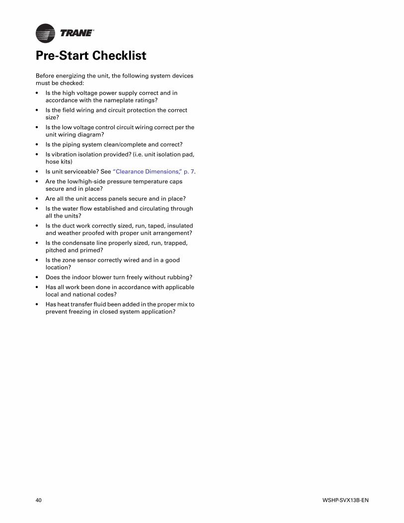
40 WSHP-SVX13B-EN
Pre-Start Checklist
Before energizing the unit, the following system devicesmust be checked:
• Is the high voltage power supply correct and inaccordance with the nameplate ratings?
• Is the field wiring and circuit protection the correctsize?
• Is the low voltage control circuit wiring correct per theunit wiring diagram?
• Is the piping system clean/complete and correct?
• Is vibration isolation provided? (i.e. unit isolation pad,hose kits)
• Is unit serviceable? See “Clearance Dimensions,” p. 7.
• Are the low/high-side pressure temperature capssecure and in place?
• Are all the unit access panels secure and in place?
• Is the water flow established and circulating throughall the units?
• Is the duct work correctly sized, run, taped, insulatedand weather proofed with proper unit arrangement?
• Is the condensate line properly sized, run, trapped,pitched and primed?
• Is the zone sensor correctly wired and in a goodlocation?
• Does the indoor blower turn freely without rubbing?
• Has all work been done in accordance with applicablelocal and national codes?
• Has heat transfer fluid been added in the proper mix toprevent freezing in closed system application?

Start-Up
Note: Start-up with the heat pump zone sensor isincluded below:
1. Cooling mode expectations: On the zone sensor, setthe fan/system mode switch to the AUTO position.
2. Reduce the zone sensor setpoint until the compressor,reversing valve, solenoid valve, and loop pump areenergized. Adjust water flow utilizing pressure/temperature plugs and comparing to tables containedin specification sheet data.
Cool air should blow from the register. Water leavingthe heat exchanger should be warmer than theentering water temperature (approximately 9-12ºF);blower operation should be smooth; compressor andblower amps should be within data plate ratings; thesuction line should be cool with no frost observed onthe refrigerant circuit.
3. Check the cooling refrigerant pressures against valuesin Table 39, p. 43.
4. Turn the zone sensor fan/system mode switch to theOFF position. Unit should stop running and thereversing valve should de-energize.
5. Leave unit off for approximately 5 minutes to allow forpressure equalization.
6. Turn the zone sensor setpoint to the highest setting.
7. Heating mode expectations: Set the zone system fan/system mode switch to the AUTO position.
8. Wait until the unit energizes the Fan and Compressorfor Heating operation.Warm air should blow from theregister. A water temperature decrease ofapproximately 5-9ºF leaving the heat exchangershould be noted.The blower and compressoroperation should be smooth with no frost observed onthe refrigeration circuit.
9. Check the heating refrigerant pressures against valuesin Table 39, p. 43.
10. Set the zone sensor setpoint to the appropriate settingaccording to the application requirements. Note theOccupied Offset selection when determining thedesired cooling and heating setpoints.
11. Instruct the owner on system operation.
Operating Pressures
There are many variables (airflow, air temperatures) in anair conditioning system that will affect operatingrefrigerant pressures and temperatures.The charts belowshows approximate conditions and is based on air flow atthe rated SCFM, entering air at 80°F(DB), 67°F(WB) incooling, 68°F(DB) in heating. (+)Heating data with 35°FEWT is based on the use of an anti-freeze solution havinga freezing point 20°F lower than the minimum expectedentering temperature.
Table 37. Checklist
MODE Heat Cool
Entering fluid temperature _______F _______F
Leaving fluid temperature _______F _______F
Temperature differential _______F _______F
Return-air temperature DB/WB _______F _______F
Supply-air temperature DB/WB _______F _______F
Temperature differential _______F _______F
Water coil heat exchanger (Water Pressure IN) _________PSIG _________PSIG
Water coil heat exchanger (Water Pressure OUT) _________PSIG _________PSIG
Pressure Differential _________PSIG _________PSIG
COMPRESSOR
Amps
Volts
Discharge line temperature (after 10 minutes) _______F _______F
Table 37. Checklist
MODE Heat Cool
WSHP-SVX13B-EN 41

Start-Up
Table 38. Operating pressures in cooling/heating - VSH
Model No.
Cooling Heating
Entering Water Temp (°F)
WaterFlow
(GPM)
Suction Pressure,
PSIG
Discharge Pressure (PSIG)
WaterTemp Rise
(°F)
Air TempDrop
°F (DB)
SuctionPressure (PSIG)
Discharge Pressure (PSIG)
Water Temp
Drop (°F)
Air TempRise
(°F DB)
VSH024
35 5.0 — — — — 84-97 252-321 5-7 15-24
35 6.2 — — — — 84-97 253-321 4-6 15-24
45 5.0 125-144 166-212 12-15 19-25 98-113 266-338 7-8 19-26
45 6.2 125-144 161-204 10-12 19-25 99-114 267-340 5-7 18-28
55 5.0 127-146 189-241 12-15 18-24 116-134 281-358 8-10 21-31
55 6.2 127-146 183-233 9-12 18-24 118-136 282-359 6-8 22-31
65 5.0 131-151 216-275 11-14 18-24 130-149 291-370 9-11 24-34
65 6.2 131-151 210-267 9-12 18-24 132-152 294-374 7-9 25-35
75 5.0 133-153 250-318 11-14 18-24 150-173 309-394 10-13 28-38
75 6.2 133-153 243-309 9-11 18-24 154-177 311-396 8-10 28-39
85 5.0 136-157 287-365 11-14 17-23 173-199 327-416 11-14 31-42
85 6.2 136-156 279-355 9-11 17-23 178-205 331-422 9-12 32-43
95 5.0 138-159 327-416 11-13 17-23 — — — —
95 6.2 138-159 319-406 9-11 17-23 — — — —
VSH033
35 6.9 — — — — 80-92 259-330 5-7 16-24
35 8.6 — — — — 80-93 259-330 4-5 16-25
45 6.9 124-142 172-219 11-15 19-25 96-110 271-345 6-8 20-27
45 8.6 123-142 166-211 9-12 19-25 97-111 272-346 5-6 19-28
55 6.9 124-142 194-247 11-15 19-24 114-131 287-365 7-9 22-31
55 8.6 124-142 188-239 9-12 19-24 115-133 289-368 6-7 22-32
65 6.9 125-144 221-281 11-14 18-24 126-145 302-384 8-10 25-35
65 8.6 125-144 214-273 9-12 18-24 128-148 304-386 7-9 25-35
75 6.9 127-146 255-324 11-14 18-24 147-169 321-408 9-12 28-39
75 8.6 127-146 248-315 9-11 18-24 150-173 323-411 8-10 29-39
85 6.9 129-148 292-371 11-14 17-23 169-195 342-436 11-13 32-43
85 8.6 128-148 284-362 9-11 17-23 174-200 345-439 9-11 33-44
95 6.9 131-150 332-423 11-13 17-23 — — — —
95 8.6 130-150 325-413 9-11 17-23 — — — —
VSV042
35 8.4 — — — — 81-93 249-317 6-7 15-23
35 10.5 — — — — 82-95 251-319 5-6 14-24
45 8.4 109-125 160-203 12-15 17-23 96-111 259-329 7-9 18-26
45 10.5 109-125 154-196 10-12 17-23 98-113 261-333 5-7 18-27
55 8.4 126-145 185-236 12-15 17-23 112-129 271-345 8-10 20-30
55 10.5 126-145 179-228 9-12 17-23 115-132 272-347 6-8 21-30
65 8.4 133-153 215-273 11-15 18-24 130-150 282-359 9-11 23-33
65 10.5 133-153 208-264 9-12 18-24 133-154 285-363 7-9 24-34
75 8.4 134-155 248-315 11-14 18-24 151-174 298-379 10-13 26-36
75 10.5 134-154 240-306 9-11 18-24 156-179 302-384 8-11 27-37
85 8.4 137-158 283-361 11-14 17-23 175-201 316-402 11-14 29-40
85 10.5 137-158 276-351 9-11 17-23 180-208 320-407 9-12 30-41
95 8.4 139-160 323-411 11-13 16-22 — — — —
95 10.5 139-160 316-402 8-11 17-23 — — — —
VSH05035 10.2 — — — — 80-92 255-324 6-7 16-25
35 12.7 — — — — 81-94 256-326 5-6 16-26
45 10.2 126-145 164-208 12-15 15-21 94-108 265-337 7-9 20-27
continued on next page
42 WSHP-SVX13B-EN

Start-Up
VSH050
45 12.7 126-145 159-202 9-12 15-21 96-110 267-340 6-7 19-29
55 10.2 128-147 188-240 11-15 17-23 108-124 277-353 8-10 22-32
55 12.7 128-147 182-232 9-12 17-23 113-130 281-358 6-8 22-32
65 10.2 129-148 216-276 11-14 18-24 123-142 292-371 9-11 25-35
65 12.7 129-148 210-267 9-12 18-24 126-146 295-375 7-9 25-36
75 10.2 131-150 250-318 11-14 18-24 144-165 309-393 10-13 28-38
75 12.7 130-150 243-309 9-11 18-24 148-170 313-399 8-10 29-39
85 10.2 133-153 285-363 11-14 17-23 167-192 328-417 11-14 31-42
85 12.7 133-153 278-354 9-11 17-23 172-198 332-423 9-12 32-43
95 10.2 135-155 325-413 11-14 17-23 — — — —
95 12.7 135-155 317-404 9-11 17-23 — — — —
VSH060
35 12.5 — — — — 82-95 271-345 6-7 19-28
35 15.6 — — — — 83-96 274-348 5-6 19-29
45 12.5 121-140 152-194 12-15 18-24 94-108 286-364 7-9 23-31
45 15.6 122-140 147-187 10-12 18-24 96-110 289-368 6-7 23-32
55 12.5 121-139 190-241 11-15 18-24 111-128 306-389 8-10 25-35
55 15.6 118-135 183-233 9-12 18-24 114-131 308-392 7-8 26-36
65 12.5 119-137 221-282 11-14 18-24 124-142 322-409 9-11 29-39
65 15.6 119-137 215-273 9-11 18-24 127-147 327-416 7-9 30-40
75 12.5 121-139 255-324 11-14 18-24 144-166 346-440 10-13 33-43
75 15.6 121-139 248-315 9-11 18-24 149-171 350-445 8-11 33-44
85 12.5 128-147 289-368 11-14 18-24 167-192 369-470 11-14 37-48
85 15.6 127-147 282-359 9-11 18-24 173-199 376-478 9-12 38-49
95 12.5 130-149 329-419 11-14 18-24 — — — —
95 15.6 129-149 322-409 9-11 18-24 — — — —
Table 38. Operating pressures in cooling/heating - VSH (continued)
Model No.
Cooling Heating
Entering Water Temp (°F)
WaterFlow
(GPM)
Suction Pressure,
PSIG
Discharge Pressure (PSIG)
WaterTemp Rise
(°F)
Air TempDrop
°F (DB)
SuctionPressure (PSIG)
Discharge Pressure (PSIG)
Water Temp
Drop (°F)
Air TempRise
(°F DB)
Table 39. Operating pressures in cooling/heating - VSV
Model No.
Cooling Heating
Entering Water Temp (°F)
WaterFlow
(GPM)
Suction Pressure,
PSIG
Discharge Pressure (PSIG)
WaterTemp Rise
(°F)
Air TempDrop
°F (DB)
SuctionPressure (PSIG)
Discharge Pressure (PSIG)
Water Temp
Drop (°F)
Air TempRise
(°F DB)
VSV024
35 — — — — — 83-95 258-328 5-6 14-23
35 — — — — — 85-98 259-330 4-5 15-24
45 5.0 125-144 154-196 11-15 18-24 98-113 275-350 6-8 18-27
45 6.2 124-143 148-189 9-12 19-24 100-115 277-352 5-7 18-28
55 5.0 128-147 180-229 11-14 18-24 114-131 288-366 7-9 21-30
55 6.2 128-147 174-222 9-12 18-24 117-134 290-369 6-8 21-31
65 5.0 132-152 209-266 11-14 18-24 129-148 304-387 8-11 24-34
65 6.2 132-151 203-258 9-11 19-24 133-153 308-391 7-9 24-34
75 5.0 134-154 241-307 11-14 18-24 148-170 321-408 10-12 27-37
75 6.2 133-153 235-299 9-11 18-24 153-176 325-414 8-10 28-38
85 5.0 136-156 277-352 11-13 17-23 169-194 341-433 11-14 31-41
85 6.2 136-156 270-344 9-11 18-23 175-201 346-441 9-11 32-42
95 5.0 138-159 316-402 10-13 17-23 — — — —
continued on next page
WSHP-SVX13B-EN 43

Start-Up
VSV024 95 6.2 138-158 309-394 8-11 17-23 — — — —
VSV033
35 — — — — — 79-91 267-339 5-7 15-24
35 — — — — — 81-94 268-341 4-5 16-25
45 6.6 116-133 159-202 12-15 22-20 94-108 283-360 6-8 19-28
45 8.3 115-133 154-196 9-12 18-24 96-110 285-363 5-7 19-28
55 6.6 120-138 186-236 12-15 18-24 110-126 297-378 7-9 22-31
55 8.3 120-138 180-229 9-12 18-24 113-130 300-381 6-8 22-32
65 6.6 124-143 214-273 12-15 18-24 126-145 317-404 8-11 25-35
65 8.3 124-143 208-265 9-12 18-24 130-150 321-409 7-9 26-36
75 6.6 126-145 247-314 11-14 18-24 146-168 337-429 10-12 28-39
75 8.3 126-145 241-306 9-11 18-24 151-173 342-435 8-10 29-40
85 6.6 129-149 282-359 11-14 17-23 167-192 359-457 11-14 32-43
85 8.3 129-149 276-351 9-11 18-24 173-199 365-465 9-11 33-44
95 6.6 132-151 322-409 11-14 17-23 — — — —
95 8.3 131-151 315-401 9-11 17-23 — — — —
VSV042
35 — — — — — 83-95 260-330 5-7 14-23
35 — — — — — 84-97 261-332 4-5 15-23
45 8.7 126-144 154-196 12-15 19-25 98-112 276-352 7-8 18-27
45 10.9 125-144 149-189 10-12 19-25 100-115 278-354 5-7 18-28
55 8.7 129-148 180-230 12-15 19-25 115-133 291-371 8-10 21-31
55 10.9 128-148 175-223 9-12 19-25 118-136 293-373 6-8 22-31
65 8.7 133-153 210-267 11-14 19-24 131-151 309-394 9-11 24-34
65 10.9 133-152 204-260 9-12 19-25 135-155 313-398 7-9 25-35
75 8.7 134-155 242-308 11-14 18-24 150-172 326-415 10-13 28-38
75 10.9 134-154 236-300 9-11 18-24 155-178 331-421 8-11 28-39
85 8.7 137-158 277-352 11-14 18-24 170-196 346-441 11-14 31-42
85 10.9 137-157 270-344 9-11 18-24 176-203 352-448 9-12 32-43
95 8.7 139-160 315-401 11-14 17-23 — — — —
95 10.9 139-160 309-393 9-11 17-23 — — — —
VSV050
35 — — — — — 81-93 273-348 6-7 16-25
35 — — — — — 83-95 275-350 5-6 17-26
45 10.4 117-134 154-196 11-15 18-24 95-109 294-375 7-9 20-30
45 13.0 117-134 151-192 9-12 18-24 98-112 296-377 6-7 21-30
55 10.4 122-140 182-231 11-15 18-24 111-127 309-394 8-10 23-33
55 13.0 121-140 177-225 9-12 18-24 114-131 313-398 6-8 24-34
65 10.4 128-147 211-268 11-14 18-24 126-145 330-420 9-12 27-37
65 13.0 128-147 205-261 9-12 19-24 130-150 334-426 7-10 28-38
75 10.4 130-149 243-309 11-14 18-24 145-167 351-446 10-13 31-41
75 13.0 129-149 237-302 9-11 18-24 151-173 357-454 9-11 32-42
85 10.4 132-152 278-354 11-14 18-24 167-192 375-477 12-15 35-46
85 13.0 132-152 272-346 9-11 18-24 173-199 383-487 10-12 36-47
95 10.4 134-154 317-403 11-13 17-23 — — — —
95 13.0 134-154 311-395 9-11 17-23 — — — —
VSV06035 12.5 — — — — 78-90 260-331 6-7 19-27
35 15.6 — — — — 80-92 262-334 5-6 18-28
continued on next page
Table 39. Operating pressures in cooling/heating - VSV (continued)
Model No.
Cooling Heating
Entering Water Temp (°F)
WaterFlow
(GPM)
Suction Pressure,
PSIG
Discharge Pressure (PSIG)
WaterTemp Rise
(°F)
Air TempDrop
°F (DB)
SuctionPressure (PSIG)
Discharge Pressure (PSIG)
Water Temp
Drop (°F)
Air TempRise
(°F DB)
44 WSHP-SVX13B-EN

Start-Up
Water Pressure Drop
Table 42, p. 45 and Table 43, p. 45 should be used to definefeet of head/pressure drop. Note that the feet of pressure(ft/head) provided is at ARI/ISO standard.
To calculate feet of head, when using gauges that read inPSIG, multiply PSI by 2.31.
Water Volume
Table 44, p. 45 and Table 45, p. 45 are provided for use incalculating glycol requirements for the unit.
VSV060
45 12.5 119-137 158-201 12-15 16-22 94-108 277-353 7-9 23-30
45 15.6 116-133 153-194 9-12 16-22 97-111 279-355 6-7 22-32
55 12.5 125-144 190-242 12-15 20-26 111-128 296-377 8-10 25-35
55 15.6 122-140 184-234 9-12 20-26 115-132 299-380 7-8 26-36
65 12.5 127-147 220-280 12-15 20-25 131-151 311-396 9-12 29-39
65 15.6 127-146 213-271 9-12 20-25 135-156 315-401 7-10 30-40
75 12.5 129-149 253-322 11-14 19-25 152-175 335-426 10-13 33-44
75 15.6 129-149 246-313 9-12 19-25 158-181 339-432 8-11 34-45
85 12.5 133-153 288-367 11-14 19-25 175-202 361-459 12-15 37-48
85 15.6 133-153 281-357 9-11 19-25 182-210 366-466 10-12 38-50
95 12.5 135-155 328-417 11-14 18-24 — — — —
95 15.6 135-155 320-407 9-11 18-24 — — — —
Table 39. Operating pressures in cooling/heating - VSV (continued)
Model No.
Cooling Heating
Entering Water Temp (°F)
WaterFlow
(GPM)
Suction Pressure,
PSIG
Discharge Pressure (PSIG)
WaterTemp Rise
(°F)
Air TempDrop
°F (DB)
SuctionPressure (PSIG)
Discharge Pressure (PSIG)
Water Temp
Drop (°F)
Air TempRise
(°F DB)
Table 40. Cooling water pressure drops (WPD) in feet ofhead - VSH
Model VSH EWT °F GPM Ft. PressureVSH024 85 6.2 3.5
VSH033 85 8.6 6.1
VSH042 85 10.5 3.0
VSH050 85 12.7 4.1
VSH060 85 15.6 5.7
Table 41. Heating water pressure drops (WPD) in feet ofhead - VSH
Model VSH EWT °F GPM Ft. PressureVSH024 70 6.2 3.8
VSH033 70 8.6 6.5
VSH042 70 10.5 3.2
VSH050 70 12.7 4.4
VSH060 70 15.6 6.1
Table 42. Cooling water pressure drops (WPD) in feet ofhead - VSV
Model VSV EWT °F GPM Ft. PressureVSV024 85 6.2 3.7
VSV033 85 8.3 6.2
VSV042 85 10.9 3.1
VSV050 85 13.0 4.2
VSV060 85 15.6 5.1
Table 43. Heating water pressure drops (WPD) in feet ofhead - VSV
Model VSV EWT °F GPM Ft. PressureVSV024 70 6.2 4.0
VSV033 70 8.3 6.7
VSV042 70 10.9 3.5
VSV050 70 13.0 4.7
VSV060 70 15.6 5.4
Table 44. Water volume - VSH
Model VSH VSH024 VSH033 VSH042 VSH050 VSH060Internal water volume (in3)
142.4 142.4 331.2 331.2 331.2
Internal water volume (ft3)
0.082 0.082 0.192 0.192 0.192
Internal water volume (gal)
0.616 0.616 1.434 1.434 1.434
Table 45. Water volume - VSV
Model VSV VSV024 VSV033 VSV042 VSV050 VSV060Internal water volume (in3)
212 212 414 414 414
Internal water volume (ft3)
0.123 0.123 0.24 0.24 0.24
Internal water volume (gal)
0.918 0.918 1.792 1.792 1.792
WSHP-SVX13B-EN 45

Maintenance
Preventive Maintenance
Maintenance on the unit is simplified with the followingpreventive suggestions:
Filter maintenance must be performed to assure properoperation of the equipment. Filters should be inspected atleast every three months, and replaced when it is evidentthey are dirty. Filter sizing is shown in Table 47, p. 46:
Check the contactors and relays within the control panel atleast once a year. It is good practice to check the tightnessof the various wiring connections within the control panel.
A strainer (60 mesh or greater) must be used on an openloop system to keep debris from entering the unit heatexchanger and to ensure a clean system.
For units on well water, it is important to check thecleanliness of the water-to-refrigerant heat exchanger.Should it become contaminated with dirt and scaling as aresult of bad water, the heat exchanger will have to be backflushed and cleaned with a chemical that will remove thescale.This service should be performed by an experiencedservice person.
CondensateTrap
For units incorporating a negative trap design, ensure thatthe condensate system is primed with water at all times.Allowing a negative, pressure condensate system to rundry could cause a break in the condensate seal allowingthe fan to draw water from the condensate line to spraymoisture into the mechanical system. By maintaining aprimed condensate trap, a seal will be created and willhelp prevent these complications.The condensate trapmust be field installed.
Note: When maintenance is performed on this unit, careshould be taken not to damage the foil faceinsulation surfaces. If damage occurs repairdamage with foil faced tape.
Table 46. Filter sizing for disposable filters - VSH
Size (60 Hz) Filter Size (Actual)
VSH 024-03316 inch x 20 inch (406 cm x 508 cm)20 inch x 20 inch (508 cm x 508 cm)
VSH 042-06020 inch x 25 inch (508 cm x 635 cm)20 inch x 30 inch (508 cm x 762 cm)
Table 47. Filter sizing for disposable filters - VSV
Size (60 Hz) Filter Size (Actual)
VSV 024-03319 7/8 inch x 24 7/8 inch
(504 mm x 632 mm)
VSV 042-06027 7/8 inch x 29 7/8 inch
(708 mm x 759 mm)
WARNING
Hazardous Voltage!
Disconnect all electric power, including remotedisconnects before servicing. Follow proper lockout/tagout procedures to ensure the power can not beinadvertently energized. Failure to disconnect powerbefore servicing could result in death or serious injury.
NOTICE
Proper WaterTreatment Required!
The use of untreated or improperly treated water incoils could result in scaling, erosion, corrosion, algae orslime. It is recommended that the services of aqualified water treatment specialist be engaged todetermine what water treatment, if any, is required.Trane assumes no responsibility for equipment failureswhich result from untreated or improperly treatedwater or saline or brackish water.
46 WSHP-SVX13B-EN

Maintenance
Figure 23. Negative pressure system
WSHP-SVX13B-EN 47

Troubleshooting
General UnitTroubleshooting
WARNING
Hazardous Service Procedures!
The maintenance and troubleshooting procedures recommended in this section of the manual could result inexposure to electrical, mechanical or other potential safety hazards. Always refer to the safety warnings providedthroughout this manual concerning these procedures. When possible, disconnect all electrical power includingremote disconnects before servicing.
Follow proper lockout/tagout procedures to ensure the power can not be inadvertently energized.When necessary towork with live electrical components, have a qualified licensed electrician or other individual who has been trained inhandling live electrical components per these tasks. Failure to follow all of the recommended safety warningsprovided, could result in death or serious injury.
Problem Heating Cooling Cause Correction
No response to any zone sensor
setting
X X Main power off Check fusesX X Defective control transformer ReplaceX X Broken or loose connection RepairX X Defective zone sensor ReplaceX X Transformer Reset Transformer
Unit short cycles X X Zone sensor improperly located Relocate
Blower runs but compressor does not
X X Supply Voltage too low CorrectX X Defective windings ReplaceX X Limit switches open Check cause/replace or repairX X Zones sensor error Check cause/replace or repairX X Compressor drive error Check cause/replace or repair
Insufficient capacity
X X Dirty filter Replace/cleanX X Blower RPM too low Correct
X X Loss of conditioned air due to leaks in ductwork Repair leaks
X Introduction of excessively hot return air CorrectX Introduction of excessively cold return air Correct
X X Low on refrigerant charge Locate leak, repair and recharge by weight (not by superheat)
X X Restricted thermal expansion valve ReplaceX X Zone sensor improperly located RelocateX X Unit undersized Recalculate heat gains/lossesX X Inadequate water flow Increase GPMX X Scaling in heat exchanger Clean or replace
X Water too hot Decrease temperatureX Water too cold Increase temperatureX X Filter drier blocked ReplaceX X Defective reversing valve Check or replace
High pressure switch open
X Inadequate GPM Increase water flow to unitX Water too hot Decrease temperature
X Inadequate air flow Check, clean blower and coilX Dirty filter Clean/replaceX X Overcharged with refrigerant Decrease chargeX X Defective pressure switch Check or replace
High head pressure
X Trash in heat exchanger BackflushX Low water flow Increase GPM
X X Overcharge of refrigerant Decrease chargeX X Non-condensable in system Evacuate and recharge by weightX X Water too hot Decrease temperatureX Dirty filter Clean/replaceX Inadequate air flow Check, clean blower and coil
48 WSHP-SVX13B-EN

Troubleshooting
Compressor Drive
Troubleshooting
The variable-speed compressor drive includes internalprotection functions that limit the compressor operation,or in some cases, disable compressor operation
completely. In an event occurs that causes the compressoroperation to shut down, the compressor drive sends abinary signal to the VSPD WSHP UC400 controller and adiagnostic is generated. Refer to Table 48, p. 49 for thecorrect DIP switch settings for each unit.The DIP switchesare located on the interface module located in thecompressor drive assembly.
Low suction pressure X X Undercharged Locate leak; repair and rechargeX X Restricted thermal expansion valve Repair / replace
X Inadequate air flow Check, clean blower and coilX Dirty filter Clean/replace
X Inadequate GPM Increase GPMLow pressure switch open X Inadequate GPM Increase GPM
X Water too cold Increase temperatureX Inadequate air flow Increase CFMX Dirty filter Clean/replace
X X Undercharged with refrigerant Increase chargeX X Defective pressure switch ReplaceX X Heat transfer fluid too cold Raise water temperature
Problem Heating Cooling Cause Correction
Table 48. DIP switch settings
Model Voltage SW1 SW2 SW3 SW4 SW5 SW6
VSVE024/033
208/60/1 OFF OFF OFF OFF OFF OFF
230/60/1 OFF OFF OFF OFF OFF OFF
460/60/3 OFF OFF OFF OFF OFF OFF
VSVE042/050/060
208/60/1 OFF OFF OFF OFF OFF ON
230/60/1 OFF OFF OFF OFF OFF ON
460/60/3 OFF OFF OFF OFF OFF ON
VSHE024/033
208/60/1 OFF OFF OFF OFF OFF OFF
230/60/1 OFF OFF OFF OFF OFF OFF
460/60/3 OFF OFF OFF OFF OFF OFF
VSHE042/050/060
208/60/1 OFF OFF OFF OFF OFF ON
230/60/1 OFF OFF OFF OFF OFF ON
460/60/3 OFF OFF OFF OFF OFF ON
WSHP-SVX13B-EN 49

Control Wiring
Figure 24. 208V single-phase wiring
50 WSHP-SVX13B-EN
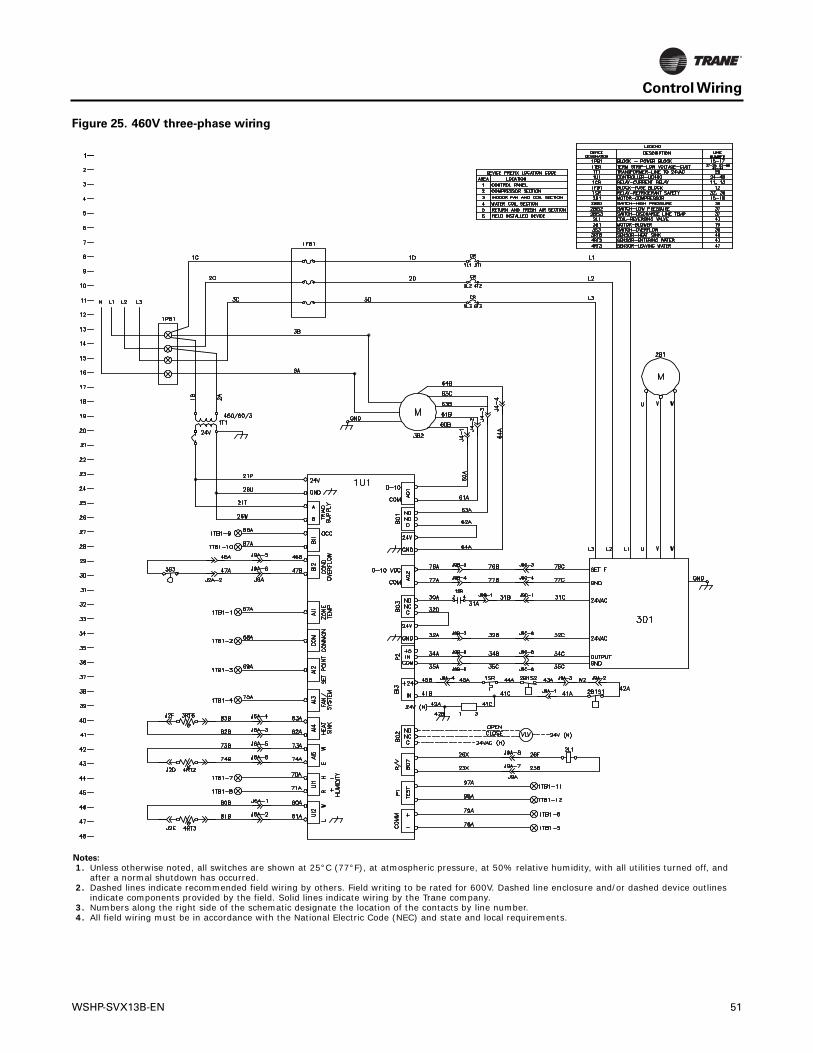
Control Wiring
Figure 25. 460V three-phase wiring
Notes:
1. Unless otherwise noted, all switches are shown at 25°C (77°F), at atmospheric pressure, at 50% relative humidity, with all utilities turned off, and after a normal shutdown has occurred.
2. Dashed lines indicate recommended field wiring by others. Field writing to be rated for 600V. Dashed line enclosure and/or dashed device outlines indicate components provided by the field. Solid lines indicate wiring by the Trane company.
3. Numbers along the right side of the schematic designate the location of the contacts by line number. 4. All field wiring must be in accordance with the National Electric Code (NEC) and state and local requirements.
WSHP-SVX13B-EN 51

Trane optimizes the performance of homes and buildings around the world. A business of Ingersoll Rand, theleader in creating and sustaining safe, comfortable and energy efficient environments, Trane offers a broadportfolio of advanced controls and HVAC systems, comprehensive building services, and parts. For moreinformation, visit www.Trane.com.
Trane has a policy of continuous product and product data improvement and reserves the right to change design and specifications without notice.
We are committed to using environmentally
conscious print practices that reduce waste.
© 2013Trane All rights reserved
WSHP-SVX13B-EN 10 Feb 2013
Supersedes WSHP-SVX13B-EN (01 Nov 2012)
Related Documents