INSTALLATION & OPERATING MANUAL X100 SERIES DC POWER POWER SYSTEM www.unipowerco.com Manual No. X100-5a © 2014 UNIPOWER LLC All Rights Reserved x100-man-Rev5a-0214.indd NORTH AMERICA • 3900 Coral Ridge Drive, Coral Springs, Florida 33065, USA • Tel: +1 954-346-2442 • Fax: +1 954-340-7901 • [email protected] EUROPE • Parkland Business Centre, Chartwell Road, Lancing BN15 8UE, ENGLAND • Tel: +44(0)1903 768200 • Fax: +44(0)1903 764540 • [email protected]

Welcome message from author
This document is posted to help you gain knowledge. Please leave a comment to let me know what you think about it! Share it to your friends and learn new things together.
Transcript

INSTALLATION & OPERATING MANUALX100 SERIES
DC POWER POWER SYSTEM
www.unipowerco.com
Manual No. X100-5a © 2014 UNIPOWER LLCAll Rights Reservedx100-man-Rev5a-0214.indd
NORTH AMERICA • 3900 Coral Ridge Drive, Coral Springs, Florida 33065, USA • Tel: +1 954-346-2442 • Fax: +1 954-340-7901 • [email protected] • Parkland Business Centre, Chartwell Road, Lancing BN15 8UE, ENGLAND • Tel: +44(0)1903 768200 • Fax: +44(0)1903 764540 • [email protected]

Page 2
X100 SERIESINSTALLATION & OPERATING MANUAL
Manual No. x100-5a x100-man-Rev5a-0214.indd
CONTENTS
1.0 INTRODUCTION .................................................................................................................42.0 FEATURES & OPTIONS ......................................................................................................53.0 SAFETY WARNINGS ..........................................................................................................54.0 WARRANTY (summary) ......................................................................................................65.0 UNPACKING AND INSPECTION ......................................................................................66.0 GENERAL SPECIFICATIONS ............................................................................................77.0 FRONT PANEL DESCRIPTION ..........................................................................................98.0 REAR PANEL DESCRIPTION ..........................................................................................109.0 CURRENT METER & LED INDICATORS .......................................................................1210.0 MAKING CONNECTIONS TO THE X100 .......................................................................1311.0 INSTALLATION .................................................................................................................1612.0 USING THE CONTROLLER WEB BROWSER INTERFACE ........................................20Appendix 1 – SNMP MIB Information .........................................................................................43Appendix 2 – Revision History ......................................................................................................47

Page 3
X100 SERIESINSTALLATION & OPERATING MANUAL
Manual No. x100-5a x100-man-Rev5a-0214.indd
FIGURES
Figure 1 X100 Compact Integrated DC Power System ...............................................................4Figure 2 Front Panels with Bezel Removed .................................................................................9Figure 3a Rear Panel – Options A & B ........................................................................................10Figure 3b Rear Panel – Option C .................................................................................................10Figure 4 Current Meter and LED Indicators (showing MAJ & FUSE alarms) .........................12Figure 5 Controller Status WEB Page (typical) .........................................................................24Figure 6 Rectifier Status WEB Page (typical) ............................................................................25Figure 7 Controller Factory Calibration WEB Page (typical) ....................................................27Figure 8 Controller Site Installation WEB Page (typical) ..........................................................28Figure 9 Alarm Configuration WEB Page (typical) ...................................................................32Figure 10 Controller Network Settings (typical) ..........................................................................35Figure 11 Controller Alarm Log WEB Page (typical)..................................................................38Figure 12 Controller Control Panel WEB Page (typical) .............................................................39Figure 13 Controller System Settings WEB Page (typical) .........................................................40Figure 14 SNMP Configuration WEB Page (typical) ..................................................................41Figure 15 Controller Help WEB Page (typical) ...........................................................................42Figure 16 About UNIPOWER Telecom WEB Page (typical) ......................................................42
TABLES
Table 1 Temp. Probe, Aux. Input & Alarm Relay Connector Pin-Out ........................................14Table 2 Ethernet Connector Pin-Out ...........................................................................................15Table 3 Input Current Ratings .....................................................................................................16Table 4 Rectifier I²C Addressing ................................................................................................25

Page 4
X100 SERIESINSTALLATION & OPERATING MANUAL
Manual No. x100-5a x100-man-Rev5a-0214.indd
1.0 INTRODUCTION
Gravitas X100 is an ultra-compact, integrated, DC power system. It consists of up to three high power-density, hot-swap rectifier modules which can produce up to 66 amperes at -54.4VDC, 99 amperes at +27.2VDC or 100 amperes at +13.6VDC. In 2+1 redundant operation the output current is up to 44 amperes at -54.4VDC, 66 amperes at +27.2VDC or 100 amperes at +13.6VDC.
The system has a configurable DC distribution panel with options of up to 10 load circuits protected either by GMT fuses or circuit breakers. Two battery breakers and a low-voltage battery disconnect are included as standard. The system also has a temperature probe for temperature compensated output from the rectifiers and an optional second probe can be used to monitor external temperature.
The intelligent control and supervisory unit communicates directly with the rectifiers to monitor and control their function. The system can be controlled by software from a remote PC via the Ethernet LAN port, using an on-board WEB server which can be accessed by any standard Java enabled WEB browser.
The complete Gravitas X100 is only 2RU high (3.47inches or 88.1mm) and is easily installed by a qualified technician. All connections are at the rear to terminal blocks. The unit may be mounted in a 19 or 23 inch rack.
.
Figure 1 - X100 Compact Integrated DC Power System

Page 5
X100 SERIESINSTALLATION & OPERATING MANUAL
Manual No. x100-5a x100-man-Rev5a-0214.indd
2.0 FEATURES & OPTIONS
2.1 Standard Features
2RU High System Unit Remote Control & Monitoring via TPC/IP Ethernet LAN Fully Integrated System Up to 66A at -54.4VDC Up to 99A at +27.2VDC Up to 100A at +13.6VDC Wide Range AC Input Up to 10 DC Load Circuits Circuit Breakers or GMT Fuses Quick and Easy Installation Universal 19/23-Inch Mounting Brackets SNMP reporting and Error Trapping
2.2 Options & Accessories
Additional Probe for External Temperature Measurement (‘T’ Option) Various AC Line cords and DC cable sets
3.0 SAFETY WARNINGS
3.1 The X100 Compact DC Power System operates at voltages that could potentially be hazardous. Furthermore, inadvertent short circuiting of the system battery and/or rectifier by misconnection or other error could be harmful. This product should be handled, tested and installed only by qualified technical persons who are trained in the use of power systems and are well aware of the hazards involved.
3.2 When operating the X100 the chassis ground terminal must be connected to the system frame ground or other proper safety ground for the protection of personnel.
3.3 All connections to the X100 should be carefully checked for errors before applying power to it.
3.4 This equipment is intended only for installation in a “RESTRICTED ACCESS LOCATION”
Page 6
X100 SERIESINSTALLATION & OPERATING MANUAL
Manual No. x100-5a x100-man-Rev5a-0214.indd
4.0 WARRANTY (summary)
X100 Series DC power systems are warranted for two (2) years from date of shipment against defects in material and workmanship. This warranty does not extend to products which have been opened, altered or repaired by persons other than persons authorized by the manufacturer or to products which become defective due to acts of God, negligence or the failure of customer to fully follow instructions with respect to installation, application or maintenance.
For a complete text of UNIPOWER’s warranty conditions please request a copy from your local Sales Office.
5.0 UNPACKING AND INSPECTION
5.1 This X100 DC power system was carefully tested, inspected and packaged for shipment from our factory. Upon receipt the unit should be carefully unpacked and inspected for any damage in shipment.
5.2 If there is evidence of damage, do not attempt to install the unit. The freight carrier should be notified immediately and a claim for the cost of the X100 should be filed with the carrier for direct reimbursement. Be sure to include the model and serial number of the damaged unit in all correspondence with the freight carrier. Also save the shipping carton and packing material as evidence of damage for the freight carrier’s inspection.
5.3 UNIPOWER will cooperate fully in case of any shipping damage investigation.
5.4 Always save the packing materials for later use in shipping the unit. Never ship the system or the rectifier modules without proper packing.

Page 7
X100 SERIESINSTALLATION & OPERATING MANUAL
Manual No. x100-5a x100-man-Rev5a-0214.indd
6.0 GENERAL SPECIFICATIONS
6.1 Inputs Supply Voltage: 85-264VAC Single Phase Each rectifier position is supplied via an individual
pair of screw terminals.
A 3-phase supply may be connected provided that the voltage presented to each individual rectifier position does not exceed 264VAC.
Supply Current: Max 17A input @ 85-264VAC per rectifier input. Battery Input: Direct connection to DC output bus or via protection
breakers. Digital alarm inputs: Volts free contact input* *Volts free contacts are internally pulled up to 5V with reference to rectifier negative
sense, these lines should not be tied to anything other than volts free contacts or floating opto-coupler outputs.
Temperature probes: Sensor with output current proportional to temperature.
6.2 Outputs
Breaker Distribution: Up to 8 circuits, maximum 50A per circuit. Fuse Distribution: Up to 10 circuits, maximum 12A per circuit. Alarm Relay Contacts: Form C, 1A max at 30VDC.
Ethernet: 10/100 Base T
6.3 Protection
Supply Input: Each rectifier is individual fused internally.
Battery: 100A Magnetic Circuit Breaker. Output Distribution: According to installed circuit breakers or fuses.
Bulk DC Bus: Rectifier Current Limiting / Battery Breaker.

Page 8
X100 SERIESINSTALLATION & OPERATING MANUAL
Manual No. x100-5a x100-man-Rev5a-0214.indd
6.4 Safety
The X100 system is compliant with UL60950-1, EN60950-1, CSA22.2-60950-1 and all other derivatives of the core IEC60950-1 standard 2nd Edition when installed correctly within a restricted access environment.
The X100 system is CE marked to indicate conformance to the European Union’s Low Voltage and EMC Directives.
6.5 EMC
The X100 complies with the following Norms when correctly installed.
Conducted Emissions: EN55022, level A
Radiated Emissions: EN55022, level A
ESD: EN61000-4-2, level 4, criterion A - 8kV contact, 15kV air.
Radiated Immunity: EN61000-4-3, level 3, criterion A - 10V/m.
Surges (power ports): EN61000-4-5, level 1, criterion A - 500V
6.6 Environmental
Operating Temperature: -40°C to 50°C
Storage Temperature: -40°C to 75°C
Humidity: 0% to 95% Non-Condensing
6.7 PhysicalSpecification
Case Material: Steel
Finish: Clear Passivated
Dimensions: 3.47H (88.1) x 17.2W(437) x 12.8D(325)
Rack Width: 19” or 23” using dual purpose kit supplied. NOTE: Mid-mount is recommended when used in
free space.

Page 9
X100 SERIESINSTALLATION & OPERATING MANUAL
Manual No. x100-5a x100-man-Rev5a-0214.indd
7.0 FRONT PANEL DESCRIPTION
OPTION A – MINIATURE CIRCUIT BREAKERS
BATTERYBREAKERS
DC DISTRIBUTION1-8 CIRCUIT BREAKERS
LOADCURRENTDISPLAY
16 LEDSTATUS & ALARM
MATRIX
HOT-SWAP RECTIFIER MODULES
OPTION B – GMT FUSES
DC DISTRIBUTION10 GMT FUSES
OPTION C – BULK FEED CIRCUIT BREAKERS
DC DISTRIBUTION1-4 CIRCUIT BREAKERS
Figure 2 - Front Panels with Bezel Removed
7.1 From left to right there are 3 rectifier slots. Each slot can accept one rectifier from the RADIAN Series rated up to 1200W output power. Only identical model rectifiers of appropriate output voltage may be installed at the same time. For example, a nominal -48V system may contain between 1 and 3 model RPCP48/22-Z OR between 1 and 3 model RPCM48/15-Z but not a mixture of the two types.
7.2 Above rectifiers is the distribution and display section. There are 3 types of DC distribution depending on the option that has been specified.
7.2.1 Option A provides up to 8 DC load circuits with miniature circuit breaker protection. Each circuit may be specified with a breaker of maximum rating 30A.
7.2.2 Option B provides a total of 10 DC load circuits with GMT fuse protection. Each circuit can employ a maximum fuse rating of 12A.

Page 10
X100 SERIESINSTALLATION & OPERATING MANUAL
Manual No. x100-5a x100-man-Rev5a-0214.indd
7.2.3 Option C provides up to 4 bulk DC load circuits with circuit breaker protection. Each circuit may be specified with a breaker of maximum rating 50A.
7.3 To the right of the DC distribution section is a display section.
7.3.1 Current Meter – displays the total system load current.
7.3.2 16 LED Matrix – provides visual indication of a variety of status and alarm condition. Full details can be found in section 9.
8.0 REAR PANEL DESCRIPTION
ETHERNETJ1
DC LOAD TERMINALS BATTERY TERMINALS(2 STRINGS)
AC INPUTSRELAY ALARMSTEMP. COMP.AUX. INPUT
J2
RESERVED FORFACTORY USE
J3
Figure 3a - Rear Panel – Options A & B
ETHERNETJ1
DC LOAD TERMINALS BATTERY TERMINALS(2 STRINGS)
AC INPUTSRELAY ALARMSTEMP. COMP.AUX. INPUT
J2
RESERVED FORFACTORY USE
J3
Figure 3b - Rear Panel – Option C
8.1 In the centre, viewed from the rear, is a bank of screw terminal block for the DC load connections.
When options A or B have been specified one terminal pair is provided for feed and return for each circuit installed; 1-8 for circuit breakers, 10 for GMT fuses.
When option C has been specified 4 pairs of bulk terminal blocks are fitted to provide one pair for feed and return for each circuit installed, from 1 to 4.
Note that the return (RTN) terminals are NOT internally connected to chassis ground.
FEED (-Ve48, +Ve24, +Ve12)RTN (+Ve48, -Ve24, -Ve12)
FEED (-Ve48, +Ve24, +Ve12)RTN (+Ve48, -Ve24, -Ve12)

Page 11
X100 SERIESINSTALLATION & OPERATING MANUAL
Manual No. x100-5a x100-man-Rev5a-0214.indd
8.2 To the right are two pairs of terminal blocks for making connections to one or two strings of batteries. Batteries are connected to the internal system bus via two magnetic circuit breakers on the front of the unit, each rated at 100A. These circuit breaker provides two functions.
8.2.1 In the first instance they enable the user to disconnect the batteries from the system for maintenance, replacement or other purposed.
8.2.2 The second function is to protect the batteries against excessive charge or discharge current. Note that charge current is normally managed by the built-in digital controller.
8.3 To the left of the DC load terminals there is a 9-way D sub connector marked RS232 mark J3.
This connector provides a ‘console’ only function to UNIPOWER service personnel and should not be connected to for any other purpose.
8.4 Immediately to the left of the RS232 connector is a bank of 18 Spring Clamp Terminals designated J2. These terminals provide connections for the battery temperature compensation probe, additional external temperature probe, the relay alarm outputs and one auxiliary digital input. They are described in detail in section 10.
8.5 To the left is the Ethernet TCP/IP connector J1. This connection uses a standard RJ45 Network connector. It is used to connect either to a Local Area Network or directly to a PC with network connection, the latter using a standard cross-over cable.
The primary means of setting up the X100 unit is via it’s built-in WEB server, which is accessed using a WEB browser via this Ethernet TCP/IP connection.
8.6 To the bottom right hand side of the unit are the AC input terminals. Three pairs of screw terminals designated L1, N1, L2, N2, L3 & N3 provide for connection of individual AC supplies to each of the installed rectifiers. In addition there are three safety ground connections just below. Once installed a plastic insulator provides protection against accidental touching of the live AC terminals.
IMPORTANT NOTE: DO NOT CONNECT THE UNIT SUCH THAT MORE THAN 264VAC WILL BE PRESENT BETWEEN THE LIVE AND NEUTRAL TERMINALS OF ANY ONE INLET SOCKET. SUCH CONNECTION MAY BE HAZARDOUS, WILL DAMAGE THE UNIT AND INVALIDATE THE WARRANTY.

Page 12
X100 SERIESINSTALLATION & OPERATING MANUAL
Manual No. x100-5a x100-man-Rev5a-0214.indd
9.0 CURRENT METER & LED INDICATORS
Figure 4 - Current Meter and LED Indicators (showing MAJ & FUSE alarms)
During normal operation only the green PWR LED is displayed along with an reading of the load current.
The LED indicators provide visual indication of both status and alarm conditions as described below:
PWR – GREEN – Indicates that the unit has power.FLT – GREEN – Indicates that the unit is in ‘Float’ mode.EQU – YELLOW – Indicated that the unit is in ‘Equalisation’ mode.BTST – YELLOW – Indicates that a battery test is in progress.MAJ – RED – Indicates a ‘Major’ (Immediate Response) alarm condition.MIN – RED – Indicates a ‘Minor’ (Scheduled response) alarm condition.ACF – RED – Indicates an AC supply failure.RFA – RED – Indicates a Rectifier module failure.OTA – RED – Indicates that the one or more of the monitored temperatures is too high.OVA – RED – Indicated that the system Bus Voltage is too high.UVA – RED – Indicates that the system Bus Voltage is too low.EVA – RED – Indicates that the system Bus Voltage is nearing the point at which the battery LVD will be opened.LVD – RED – Indicated that at least one of the two LVD contactors is open.FUSE – RED – Indicates that a monitored fuse or breaker is open.CHKB – RED – Indicates that there is a battery fault.COMM – RED – Indicates an I²C communications failure.

Page 13
X100 SERIESINSTALLATION & OPERATING MANUAL
Manual No. x100-5a x100-man-Rev5a-0214.indd
10.0 MAKING CONNECTIONS TO THE X100
10.1 DC Load Connections
The DC load distribution connections at the rear left of the unit are clearly marked as follows:
10.1.1 Option A – 1-8 miniature circuit breaker. Terminals marked 1-8 are used for breakers marked 1-8 respectively. Each
circuit has a FEED and a RETURN (RTN) connection. Terminals marked 9 and 10 are not used.
10.1.2 Option B - GMT Fuses.
Terminals marked 1-10 are used for fuse marked 1-10 respectively. Each circuit has a FEED and a RETURN (RTN) connection.
10.1.3 Option C - 1-4 bulk circuit breaker.
To allow for the possibility of individual load circuits providing in excess of 30A this configuration uses two pairs of screw terminals linked together by a small bus bar for each circuit. Terminals marked 1&2, 3&4, 5&6 and 7&8 respectively are used for Breakers 1 to 4 respectively. Terminals marked 9 and 10 are not used.
Note that in the case of -48VDC system the ‘feed’ terminals are at a negative potential with respect to the ‘return’ terminals. In the case of +24VDC and +12VDC systems the ‘feed’ terminals are at a positive potential with respect to the ‘return’ terminals.
When connecting to the DC load terminals it is important to ensure that the cables used are adequately sized to carry the expected load current for the circuit in question.
The maximum current rating for the individual load terminals is 30A for options A and B or 50A for option C, but where long cable runs to the load are expected care should be taken to avoid unacceptable cable voltage drop; this is most likely to occur at currents in excess of 20A if only a single feed and return cable are employed. It is recommended that for circuits where a 20A or greater breaker is fitted pairs of feed and return cables are installed.

Page 14
X100 SERIESINSTALLATION & OPERATING MANUAL
Manual No. x100-5a x100-man-Rev5a-0214.indd
10.2 Battery Connections
The X100 can be connected to two separate battery strings through the battery two pairs of IMO ER35 terminal blocks. These terminals accept cables in the range 10AWG to 2AWG. A minimum cable size of 4AWG is recommended when employing only the internal 100A circuit breakers for protection (see section 8.2). If a battery string is separately provided with a lower rated circuit breakers or fuse then smaller gauge cables may be used as appropriate.
10.3 Alarm Relay and Battery Temperature Probe Connections – J2
Connection to the Form-C alarm relay outputs is made through the 18-way spring clamp terminal connector. There are a total of 4 relay outputs with Normally Open, Normally Closed and Common Contacts available for connection. The individual relay contact sets are fully isolated and may be floated from GROUND by up to 100V. Maximum contact current and voltage are 1A and 30V (DC or AC) respectively. This connector accepts wire sizes from #28AWG to #10AWG.
The alarm relays are designated K1 to K4. K1 and K2 are pre-programmed for MAJOR and MINOR alarm conditions by default. K3 and K4 are not programmed for any alarm function by default and may be programmed using the Alarm ConfigurationWEB page described later in section 12.
Connection of the supplied battery temperature probe, if required, is made using terminals 1 and 2 of this same spring clamp terminal connector. An optional external temperature probe may also be connected using terminals 3 and 4. Terminals 5 and 6 allow connection of a volt free contact closure input.
J2 CONNECTIONSTERMINAL FUNCTION TERMINAL FUNCTION
1 BATT. TEMP. PROBE + 10 K2 - MIN ALARM - N/C2 BATT. TEMP. PROBE - 11 K2 - MIN ALARM - COM3 EXT. TEMP. PROBE + 12 K2 - MIN ALARM - N/O4 EXT. TEMP. PROBE - 13 K3 - FREE ALARM - N/C5 AUX. 3 CONTACT 14 K3 - FREE ALARM - COM6 AUX. 3 CONTACT 15 K3 - MREE ALARM - N/O7 K1 - MAJ ALARM - N/C 16 K3 - FREE ALARM - N/C8 K1 - MAJ ALARM - COM 17 K3 - FREE ALARM - COM9 K1 - MAJ ALARM - N/O 18 K3 - MREE ALARM - N/O
Note that terminal 1 is to the left when viewed from the rear of the system.
Table 1 - Temp. Probe, Aux. Input & Alarm Relay Connector Pin-Out

Page 15
X100 SERIESINSTALLATION & OPERATING MANUAL
Manual No. x100-5a x100-man-Rev5a-0214.indd
10.4 Ethernet Connection – J1
The X100 is connected to a TCP/IP LAN (Local Area Network) or directly to a PC using connector J1. This is a standard RJ45 network connector allowing connection of any generally available Ethernet cable. Note that if the X100 is to be connected directly to a PC rather than a LAN then a cross-over Ethernet cable will be required.
J3 CONNECTIONSTERMINAL FUNCTION
1 TX +2 TX -3 RX +4 Not Used5 Not Used6 RX - 7 Not Used8 Not Used
Table 2 - Ethernet Connector Pin-Out
10.5 RS232 Console This connector is reserved for UNIPOWER factory use.

Page 16
X100 SERIESINSTALLATION & OPERATING MANUAL
Manual No. x100-5a x100-man-Rev5a-0214.indd
11.0 INSTALLATION
The X100 can be mounted in either 19” or 23” racks by using the supplied brackets. Mount it from the front of the rack using the correct offsets to align with existing rack-mounted equipment. Once mounted in the rack the following connections must be made with the unit switched off.
CAUTION: Re-read the Safety Warnings and Precautions in Section 3. All power should be OFF for the input and output loads before making connections. Connection oftheX100chassistoframegroundshouldbemadefirst.IftheX100hasbeenturnedon before installation connections, it should be turned off and given a 5-minute waiting period for all internal energy storage capacitors to be discharged.
11.1 Input AC Power Connection
A 3-wire AC power line should be connected to the input connectors and adjacent earht points but not plugged into the AC power source. The line, neutral and ground connections should be carefully observed when making the AC connections. The AC line cord should be sized to safely carry 20 amperes AC each, minimum.
MODEL Vin AC Vout DC WATTS A @ 120Vac A @ 240VacRPCP48/22-Z 85-264 54.4 1200 11.8 6.2RPCM48/15-Z 85-264 54.4 800 7.9 4.1RPCP24/33-Z 85-264 27.2 900 8.6 4.5RPCP24/25-Z 85-264 27.2 690 6.6 3.5RPCP12/50-Z 85-264 13.6 680 7.1 3.7RPCP12/45-Z 85-264 13.6 600 6.3 3.3
Note: ratings given are at nominal voltage for sizing breakers. Label rating may be greater.
Table 3 - Input Current Ratings
11.2 Checking Outputs Turn all but one output circuit breakers to the OFF position and/or remove all but one
fuses from the GMT fuse-holder. With no loads connected and without the battery connected, plug in or connect the AC input cords one at a time to the AC power source. Be sure to use the correct AC voltage for the rectifier inputs.
Using a volt meter measure the DC voltage reading across the FEED and RTN terminals of the output that is switched on at the rear of the unit. The voltage should be approximately 54.4, 27.2, or 13.6VDC (depending on model), which is the factory setting.

Page 17
X100 SERIESINSTALLATION & OPERATING MANUAL
Manual No. x100-5a x100-man-Rev5a-0214.indd
One by one, turn each output circuit breaker to the ON position and/or insert a GMT fuse and measure the DC voltage across the corresponding output terminals. The voltage should again read approximately 54.4, 27.2, or 13.6 volts.
After each output is measured, turn OFF that circuit breaker and/or remove the GMT fuse and turn ON and/or insert a fuse in the next one.
After measuring the last circuit, turn off that breaker and/or remove the GMT fuse and make sure that all output breakers are in the OFF position and/or all fuses are removed. Next, unplug or disconnect the AC input power source.
Before touching any terminals wait 5 minutes for the internal storage capacitors to discharge.
11.3 Controller Section Operation and Settings
At this point, before the final installation connections, read section 12 covering Controller setup. Next, make any required signal connections, controller adjustments, temperature compensation adjustment and alarm enabling settings.
WARNING: Remember to take precautions each time the system is turned on and also when connecting or disconnecting the battery. Remember that the battery presents an energy hazard at its terminals. Also remember to allow 5 minutes for internal capacitors to discharge after disconnecting the AC input power and the battery.
11.4 Connection to Loads
With input AC power unplugged, the battery disconnected and no other power sources connected to the loads, make sure that all load circuit breakers are set to the OFF position and/or all GMT fuses are removed.
Connect load wires to each set of output terminals, one at a time. Note that the front panel breaker and fuse numbers directly correspond to the output terminal numbers.
Be sure to connect the polarities correctly.
11.5 Connection to Battery
WARNING: Improper polarity of the battery connection may damage the power system. Take precautions when installing the battery and note that the battery cables are “hot” (live) and present an energy hazard.

Page 18
X100 SERIESINSTALLATION & OPERATING MANUAL
Manual No. x100-5a x100-man-Rev5a-0214.indd
With AC input unplugged, remove the three rectifier modules from the system chassis. Make sure all load circuit breakers are in the OFF position and/or all GMT fuses removed. Set the battery circuit breaker to the OFF position.
Carefully connect the battery cables to the battery terminals shown in Figure 4 while observing the correct polarity as described in section 8.4.
Note that until AC power is applied to the system the controller will not activate the LVD contactor.
11.6 System Turn-On
Perform the following operations:
1. Set the battery and all load circuit breakers to the OFF position. For systems with GMT fuse distribution remove all fuses if already installed.
2. Plug in the rectifier modules.
3. Connect the AC power cables to the AC source.
4. Check that the green LED on the front panel has lit. After approximately 20 seconds for initialization the MAJA LED at least will light. The RFA LED may also light, dependent on the number of rectifiers installed at the time.
5. Set the battery circuit breaker to the ON position. Then set the load breakers to the ON position and/or insert the GMT fuses.
After approximately 5 seconds the status of various alarm LEDs will change, dependent on the number of rectifiers installed.
Using the WEB browser interface described in section 12 it is now possible to check overall system status for correct operation.
In particular, it is important to ensure that the load current reading does not exceed the maximum capacity of the installed rectifiers or, where N+1 operation is required, the maximum capacity of one less than the total number of rectifiers installed. Note also, that the system should have been sized so that a proportion of the available rectifier capacity is allocated for battery charging. Where N+1 redundant operation is used the additional ‘spare’ rectifier will normally provide this current.
Page 19
X100 SERIESINSTALLATION & OPERATING MANUAL
Manual No. x100-5a x100-man-Rev5a-0214.indd
IMPORTANT NOTES:
a) It is not possible to start the system by connecting the batteries alone.
b) During the 30 seconds initialization period the system bus voltage will be at the factory preset level of the rectifiers; nominally 54.4V, 27.2V or 13.6V depending on system voltage. After this period the internal controller will lower the output voltage by approximately 15% in order to limit current flowing to the batteries. During a following period of approximately 30 minutes the controller will ramp the system voltage up to the correct float voltage as determined by the temperature compensation algorithm.
This ‘walk-in’ function can be disabled via the controller WEB interface if it not required.

Page 20
X100 SERIESINSTALLATION & OPERATING MANUAL
Manual No. x100-5a x100-man-Rev5a-0214.indd
12.0 USING THE CONTROLLER WEB BROWSER INTERFACE
The X100 controller is provided with a built-in WEB server which can be accessed through the TCP/IP Ethernet port using a WEB browser. The WEB server employs Java Applets to continually scan system parameters and update the WEB page data. These same Applets return programming data to the DSC1000 when set-up changes need to be made.
The WEB server communicates with the browser using HTTP on IP Port 80 and the Java Applets on IP Port 8888. If any firewall or proxies are configured on the LAN that the DSC1000 is connected to it is important to ensure that these ports are open, otherwise the DSC1000 will not respond.
A genuine Java engine must be installed on the browser PC. The latest version can be downloaded and installed for free from www.java.com. Please note that installing only a browser plugin may not be sufficient for correct operation; so we recommend installing a full Java package.
If the installed version of Java is 7u45 or earlier the following procedure “Setting up Java” is not required for correct operation and cannot be implemented.
PLEASE NOTE THAT THE APPLETS WILL NOT WORK WITH JAVA VERSION 7u51. DO NOT INSTALLED THIS ON SYSTEMS USED TO MONITOR THE DSC1000.
WITH EFFECT FROM VERSION 7u60 THE FOLLOWING MUST BE IMPLEMENTED.
Setting up Java (7u60 or later only)
In order for the applets to be loaded correctly, you must add the IP address of the controller to the list of site exceptions in the java control panel. This can be found in the computer’s control panel. Once the java control panel is open, select the Security tab as below.

Page 21
X100 SERIESINSTALLATION & OPERATING MANUAL
Manual No. x100-5a x100-man-Rev5a-0214.indd
Ensure that ‘Enable Java content in the browser’ is checked and leave the “Security Level” set to “High (minimum recommended)”
Click on the Manage Site List button and the following will appear.
Click the Add button and type in the IP address of the controller in the format ‘http://xxx.xxx.xxx.xxx’ (substitute the IP address set in the controller). A warning will appear indicating that this is a security risk. Press Continue to allow the site to be added.
Now press OK and then OK again to close the Java control panel.
You should now be able to access the controller web pages and see the applets running.
Note that if you try to access a controller that has not been added to the exception list as above using a Browser with Java 7u60 or later installed you will get the following:
Note also that when accessing an allowed controller the following will appear at the start of each Browser session. Click OK to proceed. It will not appear again unless the Browser

Page 22
X100 SERIESINSTALLATION & OPERATING MANUAL
Manual No. x100-5a x100-man-Rev5a-0214.indd
is closed and re-opened.
The controller has various network programming capabilities which allow it to be connected to almost any configuration of IP network.
The default network settings that the controller is shipped with are:
IP Address – 192.168.000.200 Subnet Mask – 255.255.255.000 Gateway – 000.000.000.000 All pages served by the controller’s built-in WEB server consist of two frames; a ‘navigation’ frame on the left hand side and an ‘information/programming’ frame which occupies the majority of the browser window.
The buttons in the ‘navigation’ frame can be used at all times to jump between the various pages. Clicking on the UNIPOWER logo at the top will navigate directly to the UNIPOWER web site www.unipowerco.com.
Each of the blocks of information in the ‘information/programming’ frame is a Java applet. In some cases these applets simply collect information from the controller and presents it on-screen, in other cases the applets contain data entry fields for uploading programming information to the unit.
Note that a PC screen resolution of 1024 x 768 or higher is recommended to avoid excessive amounts of page scrolling.
The following sections describe the various WEB pages that can be viewed with the browser and give details of programming parameters that may be entered and sent to the unit.

Page 23
X100 SERIESINSTALLATION & OPERATING MANUAL
Manual No. x100-5a x100-man-Rev5a-0214.indd
IMPORTANT NOTE: The screen shots shown throughout this section are ‘typical’ examples. The exact data content will differ dependent on the system voltage and whether alterations from the default settings have been made. Settings can be returned to the factory defaults at any time by clicking on the ‘DEFAULT’ then ‘UPLOAD’ buttons on the relevant setup page. This action requires the level 1 pass code.
The factory default pass codes are:
Level 1 - 111 Level 2 - 123

Page 24
X100 SERIESINSTALLATION & OPERATING MANUAL
Manual No. x100-5a x100-man-Rev5a-0214.indd
12.1 Controller Status
When the X100 is first accessed using a WEB browser the Controller Status page shown below is downloaded.
Figure 5 - Controller Status WEB Page (typical)
This page presents two blocks of information. The top block displays a number of system status parameters by mimicking a block of LEDs. 7 of these functions, described earlier, are displayed on the front panel of the system unit.
The bottom block of information shows the following ‘live’ data:
Bus Voltage Battery Current Rectifier Current Load Current Battery Temperature External Temperature Controller Temperature No. of Rectifiers Installed (includes all rectifiers that are present regardless
of status)
If the battery or external temperature probes are not connected a reading of 25ºC will be displayed by default.

Page 25
X100 SERIESINSTALLATION & OPERATING MANUAL
Manual No. x100-5a x100-man-Rev5a-0214.indd
12.2 RectifierStatus
The Rectifier Status page presents detailed information about an individual rectifier module. Two types of data are included; ‘live’ status information and ‘static’ inventory information. In addition the controller returns the I²C address as confirmation that the unit has responded.
Figure6-RectifierStatusWEBPage(typical)
In order to obtain status information about a particular rectifier module it is necessary first to dial in the required rectifier address according to the table below and then click on the SELECT button to confirm the request.
RECTIFIER I²C ADDRESSINGRectifierPosition
Base System Expander ShelfAddress Address
Left 0 4Center 1 5Right 2 6
Table4-RectifierI²CAddressing

Page 26
X100 SERIESINSTALLATION & OPERATING MANUAL
Manual No. x100-5a x100-man-Rev5a-0214.indd
A few seconds after the SELECT button has been pressed the X100 will respond and the status and inventory information will be updated. ‘Live’ data is presented in the form of 8 colored indicator blocks to the left. A green block indicates a ‘good’ condition and a red block indicates a ‘bad’ condition. In addition the unit’s internal temperature is presented on the right.Note that Sigma Series rectifiers include a single fan only and that two of the status indicator blocks will always be grayed out.
‘Inventory’ data, presented on the right below the temperature measurement includes, among other items, rectifier model number Serial Number and Revision Number.
12.2.1 RectifierInhibit(Shutdown)
The X100 includes a facility that enables the user to manually inhibit or shutdown individual rectifiers. This may be desirable when a particular rectifier is to be removed from the system for maintenance, although all UNIPOWER rectifiers are Hot-Swap, or for some other reason.
To inhibit a rectifier first dial in the I²C address of the required unit and the click on SHUTDOWN.
To restart a rectifier that has been inhibited dial in the I²C address of the required unit and the click on RUN.
Note that any rectifiers which have been inhibited will remain in this state
until they are either restarted using the above method or the AC power is recycled.

Page 27
X100 SERIESINSTALLATION & OPERATING MANUAL
Manual No. x100-5a x100-man-Rev5a-0214.indd
12.3 Controller Factory Calibration
The primary purpose of the Controller Factory Calibration page is to allow UNIPOWER to setup a range of necessary calibration values to ensure correct operation.
When this page is requested and the Java applet has loaded a dialog requesting the Level 2 Pass code is presented. Once the pass code has been entered click ENTER and the page will then be updated with current values after a few seconds.
Figure 7 - Controller Factory Calibration WEB Page (typical)
NOTE: It should not normally be necessary for changes to be made to this page other than to change the pass codes if so desired.
The factory default pass codes are:
Pass code Level 1 – 111Pass code Level 2 – 123
Page 28
X100 SERIESINSTALLATION & OPERATING MANUAL
Manual No. x100-5a x100-man-Rev5a-0214.indd
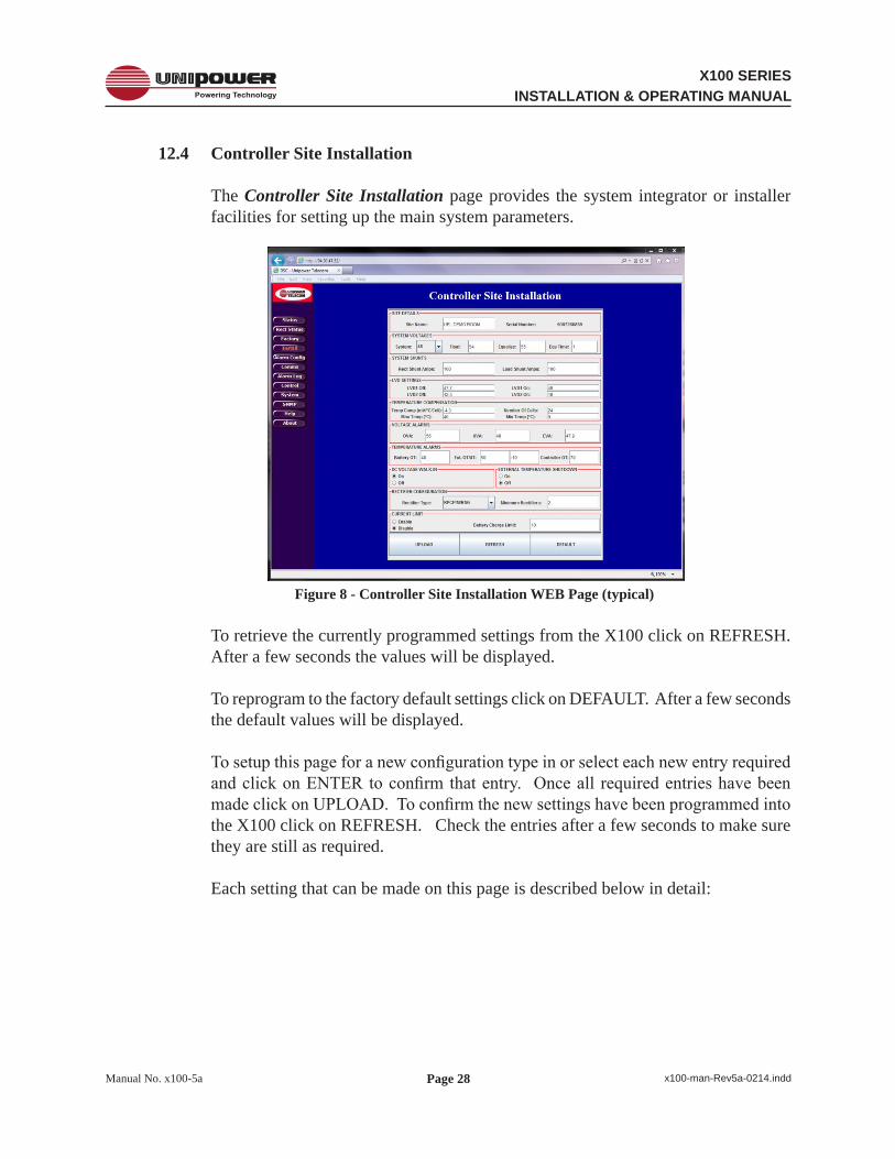
12.4 Controller Site Installation
The Controller Site Installation page provides the system integrator or installer facilities for setting up the main system parameters.
Figure 8 - Controller Site Installation WEB Page (typical)
To retrieve the currently programmed settings from the X100 click on REFRESH. After a few seconds the values will be displayed.
To reprogram to the factory default settings click on DEFAULT. After a few seconds the default values will be displayed.
To setup this page for a new configuration type in or select each new entry required and click on ENTER to confirm that entry. Once all required entries have been made click on UPLOAD. To confirm the new settings have been programmed into the X100 click on REFRESH. Check the entries after a few seconds to make sure they are still as required.
Each setting that can be made on this page is described below in detail:

Page 29
X100 SERIESINSTALLATION & OPERATING MANUAL
Manual No. x100-5a x100-man-Rev5a-0214.indd
SITE DETAILS
Site Name – Optional setting which may be used to identify the location of the unit.
Serial Number – Displays the unit serial number. (Cannot be changed.)
SYSTEM VOLTAGES
System – Dial in the Nominal system voltage; 12V, 24V or 48V.
Float – Enter the float voltage in accordance with the specifications of the batteries that are being employed with the system.
Equalize – Enter the equalization voltage in accordance with the specifications of the batteries that are being employed with the system.Equ Time – Enter the desired time that the system should remain in equalize mode in accordance with the specifications of the batteries that are being employed with the system.
SYSTEM SHUNTS
Rect Shunt Amps – This is the 50mV Full-Scale rating for the internal shunt that is used to measure the total rectifier current. THIS SETTING SHOULD NOT BE CHANGED.
Load Shunt Amps – This is the 50mV Full-Scale rating for the shunt that is used to measure the total load current. THIS SETTING SHOULD NOT BE CHANGED.
LVD SETTINGS
LVD1 Off – Enter the voltage at which the LVD1 contactor will open during a battery discharge. The factory default setting is that recommended for most sealed lead acid batteries.
LVD1 On – Enter the voltage at which the LVD1 contactor will re-connect once the rectifiers are running. The factory default setting is that recommended for most sealed lead acid batteries.
LVD2 Off & LVD2 On – These settings are not required for the X100.
Page 30
X100 SERIESINSTALLATION & OPERATING MANUAL
Manual No. x100-5a x100-man-Rev5a-0214.indd
TEMPERATURE COMPENSATION
Temp Comp (mV/°C/Cell) – Enter the temperature compensation slope value in accordance with the specifications of the batteries that are being employed with the system.
Number Of Cells – Enter the total number of battery cells.
Max Temp (°C) – Enter the maximum temperature at which temperature compensation may be applied. Above this temperature the X100 will cease to apply further compensation to the float voltage.
Min Temp (°C) – Enter the minimum temperature at which temperature compensation may be applied. Below this temperature the X100 will cease to apply further compensation to the float voltage.
VOLTAGE ALARMS
OVA – Enter the voltage above which the Over-Voltage Alarm will be triggered.
UVA – Enter the voltage below which the Under-Voltage Alarm will be triggered.
EVA – Enter the voltage below which the End-Voltage Alarm will be triggered.
TEMPERATURE ALARMS
Battery OT – Enter the temperature at which the battery Over-Temperature alarm will be triggered.
External OT/UT – Enter the temperature at which the external Over-Temperature and Under-Temperature alarms will be triggered.
Controller OT – Enter the temperature at which the controller’s internal Over-Temperature alarm will be triggered. THIS SETTING SHOULD NOT NORMALLY BE CHANGED.

Page 31
X100 SERIESINSTALLATION & OPERATING MANUAL
Manual No. x100-5a x100-man-Rev5a-0214.indd
DC WALK-IN
ON (Default) – Causes the controller to slowly ramp up the DC rectifier voltage when AC is applied. The voltage will rise from approximately 45V (for 48V systems), 22V (for 24V systems) and 11V (for 12V systems) up to the float voltage. The ramp-up time is several minutes and cannot be adjusted. The purpose of this feature is to avoid initially large battery charging currents.
OFF – Causes the controller to program all rectifiers to the float voltage almost immediately after AC is applied. Battery charging current will only be limited by the current limit of the rectifiers.”
EXTERNAL TEMPERATURE SHUTDOWN
THIS FACILITY MUST NOT BE ENABLED IN ANY STANDARD SYSTEM AS IT MAY PRODUCE UNPREDICTABLE RESULTS.
RECTIFIER CONFIGURATION
Rectifier Type – This selects the type of rectifier installed in the system from the drop-down list. In the X100 this is factory preset to RPCM/P and SHOULD NOT BE CHANGED.
Minimum Rectifiers – Enter the minimum number of rectifiers that is required to provide sufficient current to the load and to simultaneously re-charge the batteries from a fully discharged state in the desired time according to the specification of the batteries being employed with the system.
CURRENT LIMIT
Select the appropriate button for ENABLE or DISABLE as required.Battery Charge Limit – When enabled enter the maximum desired battery charge current.
Using this setting the X100 will intelligently control the rectifier float voltage such that the battery charge current never exceeds the set value.

Page 32
X100 SERIESINSTALLATION & OPERATING MANUAL
Manual No. x100-5a x100-man-Rev5a-0214.indd
12.5 AlarmConfiguration
The Alarm Configuration page presents a matrix of tick boxes which are used to programme how certain system conditions affect the actions of the alarm relays and front panel LEDs. It is also used to define the ‘good’ condition (polarity) of the auxiliary digital input. The screen shot below shows the factory default settings.
Figure9-AlarmConfigurationWEBPage(typical)
12.5.1 Alarm Matrix Programming
K1 MAJ – An item ticked in this column will enable the MAJOR alarm relay when active. Any item that is considered to represent a condition which should be acted upon immediately should be ticked.
K2 MIN – An item checked in this column will enable the MINOR alarm relay when active. Any item that is considered to represent a condition that can wait for action at a later time should be ticked.
K3 & K4 – A ticked item in any of these columns will activate the relevant auxiliary alarm relay.
Note that K5 – K8 are not installed in the X100 system.
MAJ LED – An item ticked in this column will enable the MAJOR alarm LED when active.

Page 33
X100 SERIESINSTALLATION & OPERATING MANUAL
Manual No. x100-5a x100-man-Rev5a-0214.indd
MIN LED – An item ticked in this column will enable the MINOR alarm LED when active.
ACF LED – An item ticked in the column will activate the ACF LED when the condition occurs.
RFA LED – An item ticked in the column will activate the RFA LED when
the condition occurs.
OTA LED – An item ticked in the column will activate the OTA LED when the condition occurs.
OVA LED – An item ticked in the column will activate the OVA LED when the condition occurs.
UVA LED – An item ticked in the column will activate the UVA LED when the condition occurs.
EVA LED – An item ticked in the column will activate the EVA LED when the condition occurs.
LVD LED – An item ticked in the column will activate the LVD LED when the condition occurs.
FUSE LED – An item ticked in the column will activate the FUSE LED when the condition occurs.
CHKB LED – An item ticked in the column will activate the CHKB LED when the condition occurs.
COM LED – An item ticked in the column will activate the COM LED when the condition occurs.
FLT LED – An item ticked in the column will activate the FLT LED when the condition occurs.
EQU LED – An item ticked in the column will activate the EQU LED when the condition occurs.
BTST LED – An item ticked in the column will activate the BTST LED when the condition occurs.

Page 34
X100 SERIESINSTALLATION & OPERATING MANUAL
Manual No. x100-5a x100-man-Rev5a-0214.indd
EMAIL – When the email reporting feature is activated ticking an item in this column results in an email message being sent immediately.
12.5.2 Aux. Input Polarities
By selecting the NO or NC radio buttons for the AUX 3 input the ‘good’ condition can be set to either Normally Open or Normally Closed respectively.
NOTE THAT THE LVD AND FUSE SETTINGS ARE PRESET AND SHOULD NOT BE CHANGED.
AUX 4 to AUX 8 are not fitted on the X100 system.
Once the required alarm and input polarity settings have been selected it is necessary to click on the UPLOAD button to store the new settings in the unit’s memory. To confirm that the new settings have been received and programmed click on the REFRESH button and wait a few seconds for the unit to respond. If no changes are apparent then the unit has been successfully reprogrammed.
To return the unit to the factory default settings click on the DEFAULT button

Page 35
X100 SERIESINSTALLATION & OPERATING MANUAL
Manual No. x100-5a x100-man-Rev5a-0214.indd
12.6 Comms
Clicking on the Comms button loads to Controller Network Settings page. This page is used to setup the Ethernet and E-Mail communications settings.
Figure 10 - Controller Network Settings (typical)
12.6.1 Ethernet Settings
12.6.1.1 IP Address
This setting defines the IP Address for the controller.
The default factory setting of 192.168.0.200 is a designated ‘private’ IP Address commonly used in IP based local area networks behind proxies, NAT routers or network bridges.
To enter a new IP address use the up/down arrows to dial in the required numbers or type them directly into the boxes as required. It is important to press the ENTER key on completion.
12.6.1.2 Subnet Mask
This setting defines the Subnet Mask associated with the above IP Address.
The default factory setting is 255.255.255.0.

Page 36
X100 SERIESINSTALLATION & OPERATING MANUAL
Manual No. x100-5a x100-man-Rev5a-0214.indd
To alter the Subnet mask use the up/down arrows to dial in the required numbers or type them directly into the boxes as required. It is important to press the ENTER key on completion.
12.6.1.3 Default Gateway
This setting defines the Network Gateway to which the controller will route all IP traffic that is destined for any location outside the LAN to which it is connected. This setting would normally be the address for the Proxy, NAT Router or Bridge that routes network traffic to the Internet or other WAN segments.
The default factory setting is 0.0.0.0, i.e. all traffic is retained within the LAN environment.
To alter the Default Gateway use the up/down arrows to dial in the required numbers or type them directly into the boxes as required. It is important to press the ENTER key on completion.
12.6.2 E-Mail Settings
12.6.2.1 Mail Host
This setting is the IP Address of the E-Mail Server that will route SMTP messages sent by the controller.
To set this address use the up/down arrows to dial in the required numbers or type them directly into the boxes as required. It is important to press the ENTER key on completion.
12.6.2.2 Mail Service
Select the ETHERNET radio button to switch on the E-Mail alarm facility, select the DISABLE radio button to switch it off.
12.6.2.3 E-Mail 1, 2 & 3
The X100 is able to send alarm messages to up to three unique email addresses.
Type in the desired address in the E-Mail 1 box using the normal name@domain format and press the ENTER key to confirm.
Repeat as required for E-Mail 2 and E-Mail 3.
Page 37
X100 SERIESINSTALLATION & OPERATING MANUAL
Manual No. x100-5a x100-man-Rev5a-0214.indd
12.6.2.4 Controller E-Mail
The X100 requires an email address of its own to send email alarm messages. Note, however, that it is unable to receive messages sent to this address.
Type in the desired address in the Controller E-Mail box using the normal name@domain format and press the ENTER key to confirm.
Once all desired Ethernet and E-Mail settings have been entered click on the UPLOAD button to programme them into the controller. To confirm successful programming on these setting click on the REFRESH button, wait a few seconds for the unit to respond and then ensure that the desired settings are returned by the unit.
CAUTION: Once a new IP Address has been uploaded it will be necessary to redirect the browser to this new address in order to access the WEB pages.
Page 38
X100 SERIESINSTALLATION & OPERATING MANUAL
Manual No. x100-5a x100-man-Rev5a-0214.indd
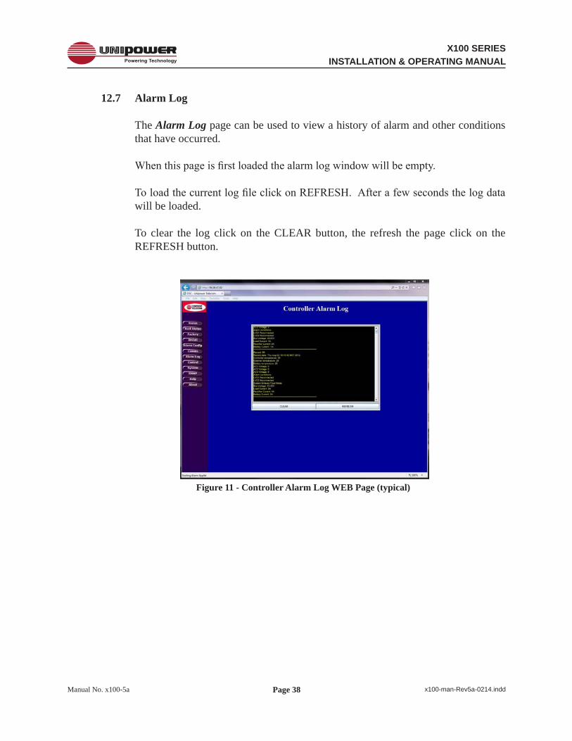
12.7 Alarm Log
The Alarm Log page can be used to view a history of alarm and other conditions that have occurred.
When this page is first loaded the alarm log window will be empty.
To load the current log file click on REFRESH. After a few seconds the log data will be loaded.
To clear the log click on the CLEAR button, the refresh the page click on the REFRESH button.
Figure 11 - Controller Alarm Log WEB Page (typical)

Page 39
X100 SERIESINSTALLATION & OPERATING MANUAL
Manual No. x100-5a x100-man-Rev5a-0214.indd
12.8 Control
The Controller Control Panel page is used to remotely switch the system between FLOAT and EQUALIZE modes. This page displays various system status functions enabling the operator to monitor these system parameters from a remote location.
To set the system to equalize mode click on the EQUALIZE button. After a few seconds the unit will respond by switching off the FLT LED indicator and switching on the EQU LED indicator.
To return the system to float mode, click on the FLOAT button. The unit will respond by returning the FLT and EQU LED indicators to their normal state.
Note that if the unit is not returned to float mode manually it will be returned automatically after the pre-programmed time has elapsed.
Figure 12 - Controller Control Panel WEB Page (typical)
Page 40
X100 SERIESINSTALLATION & OPERATING MANUAL
Manual No. x100-5a x100-man-Rev5a-0214.indd
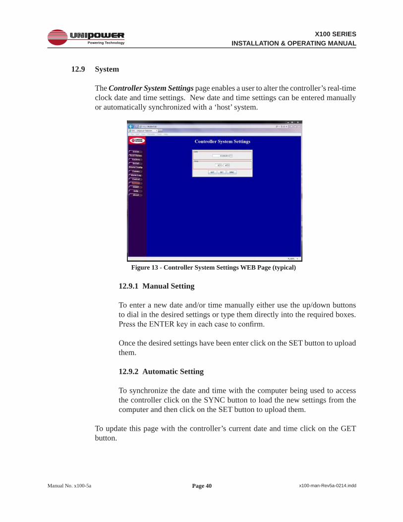
12.9 System
The Controller System Settings page enables a user to alter the controller’s real-time clock date and time settings. New date and time settings can be entered manually or automatically synchronized with a ‘host’ system.
Figure 13 - Controller System Settings WEB Page (typical)
12.9.1 Manual Setting
To enter a new date and/or time manually either use the up/down buttons to dial in the desired settings or type them directly into the required boxes. Press the ENTER key in each case to confirm.
Once the desired settings have been enter click on the SET button to upload them.
12.9.2 Automatic Setting
To synchronize the date and time with the computer being used to access the controller click on the SYNC button to load the new settings from the computer and then click on the SET button to upload them.
To update this page with the controller’s current date and time click on the GET button.

Page 41
X100 SERIESINSTALLATION & OPERATING MANUAL
Manual No. x100-5a x100-man-Rev5a-0214.indd
12.10 SNMP
The SNMP Configuration page is used to setup the controller’s SNMP System Information, Alarm Trap and Agent Information parameters. It also allows the SNMP feature to be activated.
Figure14-SNMPConfigurationWEBPage(typical)
Note: It is assumed that customers wishing to employ the SNMP features of the X100 will be familiar with the necessary set-up procedure for this page.
As with all other WEB pages described in this manual it is necessary to click on UPLOAD to programme the desired settings and to click on REFRESH to review them.
Clicking on ACTIVATE will have no effect if the SNMP feature has not been installed in the unit.
The X100 MIB, detailed in Appendix 3 of this manual is available from the software download section on the following page of the UNIPOWER web site:
www.unipowerco.com/operating-manuals

Page 42
X100 SERIESINSTALLATION & OPERATING MANUAL
Manual No. x100-5a x100-man-Rev5a-0214.indd
12.11 Help
The Controller Help Page provides a few quick reminder notes. For more detailed help the user is referred to this manual.
Figure 15 - Controller Help WEB Page (typical)
12.12 About
The About UNIPOWER Telecom page provides contact information in case additional technical or other support is required.
Figure 16 - About UNIPOWER Telecom WEB Page (typical)

Page 43
X100 SERIESINSTALLATION & OPERATING MANUAL
Manual No. x100-5a x100-man-Rev5a-0214.indd
Appendix 1 – SNMP MIB Information
The SNMP feature provides status read-out and alarm trapping only. All parameters described in this appendix are therefore read-only.
Refer to the appropriate sections earlier in the main body of this manual for system set-up.
Parameters for UNIPOWER X100 Remote Access Controller MIB
1. Voltages
Bus Voltage - Description: Live data giving actual voltage of system bus.
2. Currents
Battery Current - Live data giving actual current drawn from or into battery string(s). Rectifier Current - Live data giving actual current drawn from rectifier power supply system. Load Current - Live data giving actual current delivered to the load.
3. Temperatures
Battery Temperature - Live data giving actual temperature of battery string. External Temperature - Live data giving actual temperature of external sensor. Controller Temperature - Live data giving actual temperature within the controller enclosure.
4. RectifierInfo Number of Rectifiers - Live data giving number of rectifiers detected by the controller.
5. Auxiliary Inputs
These are all part of one status flag held within the controller.
Digital Input 1 (Low Voltage Disconnect State) Digital Input 2 (Fuse/Breaker State) Digital Input 3 Digital Input 4 Digital Input 5 Digital Input 6 Digital Input 7 Digital Input 8

Page 44
X100 SERIESINSTALLATION & OPERATING MANUAL
Manual No. x100-5a x100-man-Rev5a-0214.indd
6. Alarms
These are all part of one alarm status flag held within the controller. ACFAIL - Indicates an AC Failure detected by the power supply rectifiers or an external
sensor.
MAJOR - Indicates that a major alarm condition requiring immediate attention has been detected by the controller.
MINOR - Indicates that a minor alarm condition requiring attention at the next scheduled maintenance has been detected by the controller.
SINGLE RECTIFIER FAILURE (SRFA) - The controller has detected that a single rectifier has failed
MULTI RECTIFIER FAILURE (MRFA) - The controller has detected that multiple rectifiers have failed.
OVER TEMPERATURE ALARM (OTA) - The controller has detected an over temperature condition on battery/external/controller temperature sensor.
OVER VOLTAGE ALARM (OVA) - The controller has detected an over voltage condition on the bus.
UNDER VOLTAGE ALARM (UVA) - The controller has detected an under voltage condition on the bus.
END VOLTAGE ALARM (EVA) - The controller has detected an End Voltage condition, i.e. the batteries are near end of discharge.
LOW VOLTAGE DISCONNECT ALARM (LVD) - The controller has detected that one of the LVDs is open.
FUSE ALARM - The controller has detected that a fuse or breaker is open.
CHECK BATTERY (CHKBAT) - The controller has detected a fault with the battery string(s) either temperature or current related.
COMMUNICATION FAULT (COMM) - The controller has detected a problem with the internal I²C bus.

Page 45
X100 SERIESINSTALLATION & OPERATING MANUAL
Manual No. x100-5a x100-man-Rev5a-0214.indd
7. Settings
OVER VOLTAGE ALARM SETTING - Setting for over voltage alarm.
UNDER VOLTAGE ALARM SETTING - Setting for under voltage alarm.
END VOLTAGE ALARM SETTING - Setting for end voltage alarm.
LVD1OFF SETTING - Setting for voltage at the point where LVD1 will be shut off.
LVD1ON SETTING - Setting for voltage at the point where LVD1 will be turned on.
LVD2OFF SETTING - Setting for voltage at the point where LVD2 will be shut off.
LVD2ON SETTING - Setting for voltage at the point where LVD2 will be turned on.
FLOAT VOLTAGE - Voltage setting for the bus in float mode (modified by temp. compensation).
EQUALIZE VOLTAGE - Voltage setting for the bus in equalization mode.
NOMINAL SYSTEM VOLTAGE - The nominal system voltage (12, 24 or 48).
CONTROLLER OVER TEMPERATURE ALARM - The controller temperature, in degrees Celsius, above which an over temperature alarm will activate.
BATTERY OVER TEMPERATURE ALARM - The battery temperature, in degrees Celsius, above which an over temperature alarm will activate.
EXTERNAL OVER TEMPERATURE ALARM - The external temperature, in degrees Celsius, above which an over temperature alarm will activate.
TEMPERATURE COMPENSATION SLOPE - The parameter applied, in millivolts/°C/cell, to the float voltage to achieve temperature compensation.
TEMPERATURE COMPENSATION MAX TEMPERATURE - The temperature above which no further temperature compensation will be applied.
TEMPERATURE COMPENSATION MIN TEMPERATURE - The temperature below which no further temperature compensation will be applied.

Page 46
X100 SERIESINSTALLATION & OPERATING MANUAL
Manual No. x100-5a x100-man-Rev5a-0214.indd
8. Identification
SITE NAME - Holds the name of the site/system.
SERIAL NUMBER - Holds the serial number of the site/system.
9. SNMP Traps
The X100 will issue a trap if any of the alarm conditions mentioned above are activated.
A trap will also be issued when an alarm condition is cleared.
To obtain a copy of the latest X100 MIB download it from:
http://www.unipowerco.com/operating-manuals
or contact one of our sales offices.

Page 47
X100 SERIESINSTALLATION & OPERATING MANUAL
Manual No. x100-5a x100-man-Rev5a-0214.indd
This document is believed to be correct at time of publication and UNIPOWER LLC accepts no responsibility for consequences from printing errors or inaccuracies. Specifications are subject to change without notice.
Appendix 2 – Revision History
Rev.#
Date Detail Page
1 02/09 First Release2 02/09 Clarifications & corrections various3 08/12 Update screenshots 24, 25,
27, 28, 32, 35,38-42
4a 05/13 SNMP now standard various5 01/14 Update to include firmware rev. 4.03 and Java information various5a 02/14 Added new section 10.2 - battery connections. Renumbered previous sections
10.2 to 10.4 as 10.3 to 10.514-15
Related Documents