15 Installation of Submarine Pipelines 15.1 General This Chapter will address the installation of submarine pipelines used for the transmission of petroleum products, gas, water, slurries, and effluents. The diameter of steel submarine pipelines typically runs from 75 mm (3 in.) up to 150 mm (54 in.) with occasional lines running 1800 mm (72 in.). Diameters of steel pipe worldwide are often expressed in inches, even though all other units are metric; this is due to their historical tie to the U.S. petroleum industry. The steel for these lines is usually of relatively high yield strength, 350–500 MPa (50,000– 70,000 psi), and is selected for weldability. Wall thickness will normally run from 10 to 75 mm (3/8–3 in.) with the upper limit again being constrained by weldability. Almost all steel pipelines have been joined by full-penetration welds, especially in the petroleum industry, where pressures typically run 1500 psi (10 MPa) and leakage of oil or gas is unacceptable. Consideration is being given, however, to the use of mechanical joints, for example, joints similar to those used with well casing. Developmental work continues on explosively and hydraulically expanded connections. In a few cases, flanged connec- tions are used, but these are for lower pressures, which are used in off-loading of tankers. Since most submarine pipelines are installed empty, they are subjected during installa- tion to high hydrostatic pressure, along with whatever bending may be taking place. They are laid under axial tension. Buckling under combined loading becomes a principal design consideration. Tolerances are consequently of great importance, out-of-roundness and wall thickness being the most critical. The steel is protected from external corrosion by coatings such as bitumastic or epoxy, supplemented by cathodic protection, usually sacrificial anodes. Internally, the line may be uncoated if it is to be in petroleum service, or it may be internally coated with epoxy, polyurethane, or polyethylene or cement lined when it will carry seawater or corrosive substances. The external coating may be further protected from abrasion by concrete or fiberglass wrapping. To give stability to the line when in service, especially those lines which must be emptied at some stage of their life or which carry a low-density material like gas, the line must have net negative buoyancy. This is usually supplied by concrete weight coating (which can also serve to protect the anticorrosion coatings) or by increasing the wall thickness of steel (see Figure 15.1). A number of pipelines have experienced “floating up” off the seafloor due to spalling and shedding of their concrete coat. This indicates that the reinforcing mesh may have been underdesigned or that the pipelines may have been subjected to excessive overstress during installation. The latter is within the purview of this book. It appears that most such cases of damage have occurred during the more severe sea states when the pipe laying barge was subjected 583 q 2007 by Taylor & Francis Group, LLC

Welcome message from author
This document is posted to help you gain knowledge. Please leave a comment to let me know what you think about it! Share it to your friends and learn new things together.
Transcript

15Installation of Submarine Pipelines
q 200
15.1 General
This Chapter will address the installation of submarine pipelines used for the transmissionof petroleum products, gas, water, slurries, and effluents.
The diameter of steel submarine pipelines typically runs from 75 mm (3 in.) up to150 mm (54 in.) with occasional lines running 1800 mm (72 in.). Diameters of steel pipeworldwide are often expressed in inches, even though all other units are metric; this is dueto their historical tie to the U.S. petroleum industry.
The steel for these lines is usually of relatively high yield strength, 350–500 MPa (50,000–70,000 psi), and is selected for weldability. Wall thickness will normally run from 10 to75 mm (3/8–3 in.) with the upper limit again being constrained by weldability.
Almost all steel pipelines have been joined by full-penetration welds, especially in thepetroleum industry, where pressures typically run 1500 psi (10 MPa) and leakage of oil orgas is unacceptable. Consideration is being given, however, to the use of mechanical joints,for example, joints similar to those used with well casing. Developmental work continueson explosively and hydraulically expanded connections. In a few cases, flanged connec-tions are used, but these are for lower pressures, which are used in off-loading of tankers.
Since most submarine pipelines are installed empty, they are subjected during installa-tion to high hydrostatic pressure, along with whatever bending may be taking place. Theyare laid under axial tension. Buckling under combined loading becomes a principal designconsideration. Tolerances are consequently of great importance, out-of-roundness andwall thickness being the most critical.
The steel is protected from external corrosion by coatings such as bitumastic or epoxy,supplemented by cathodic protection, usually sacrificial anodes. Internally, the line maybe uncoated if it is to be in petroleum service, or it may be internally coated with epoxy,polyurethane, or polyethylene or cement lined when it will carry seawater or corrosivesubstances. The external coating may be further protected from abrasion by concrete orfiberglass wrapping. To give stability to the line when in service, especially those lineswhich must be emptied at some stage of their life or which carry a low-density materiallike gas, the line must have net negative buoyancy. This is usually supplied by concreteweight coating (which can also serve to protect the anticorrosion coatings) or by increasingthe wall thickness of steel (see Figure 15.1). A number of pipelines have experienced“floating up” off the seafloor due to spalling and shedding of their concrete coat. Thisindicates that the reinforcing mesh may have been underdesigned or that the pipelinesmay have been subjected to excessive overstress during installation.
The latter is within the purview of this book. It appears that most such cases of damagehave occurred during the more severe sea states when the pipe laying barge was subjected
583
7 by Taylor & Francis Group, LLC

Bitumastic orepoxy coating
Steel pipeMesh
Field coating
Bendingcompression
Circuferentialcompression due
to hydrostatic pressure
Bendingtension
Anode bracelet
Concreteweight coating
Double pandom length
Axial tension applied during laying
40
FIGURE 15.1Typical steel submarine pipeline, showing stresses incurred during installation.
Construction of Marine and Offshore Structures584
to severe dynamic surge. If the coating was not only cracked but delaminated from thepipe, then transient pore pressures under the storm waves break the coating off in pro-gressive failure. This type of failure has occurred a number of times during pipe-pullingoperations. The most obvious solution is to increase the amount of circumferential reinfor-cing in the coating. Since the coated pipe is usually furnished by the oil company, thisobviously presents a contractual problem to pipeline installation contractors. Neverthe-less, contractors may often find it in their best interests to verify the amount ofcircumferential reinforcing and, where necessary, recommend increased reinforcement.
Pipelines are basically designed to lie on the seafloor or in a trench in the seafloor, withmore or less continuous support. However, unsupported spans may occur in rough, rockyseafloors or where the sands move under the action of currents and waves. The designerwill have set limits on the unsupported span lengths, which the contractor must notexceed; this may require either prior seafloor leveling or post-installation support.
q 2007 by Taylor & Francis Group, LLC

Installation of Submarine Pipelines 585
Lines are buried beneath the seafloor in many areas of the world to protect them fromfishing trawl boards, from dragging anchors, and from fatigue due to vortex shedding in acurrent. Usually, the trenches are backfilled with the excavated soil or covered with rock,but in many cases, natural sedimentation is counted on to fill the trench. Cyclic oscillationof pore pressures due to the passing of long period wave crests and troughs may “pump”the pipeline out of the trench. For this reason, pipelines in the North Sea are laid intrenches that are then filled with crushed rock.
As noted earlier, the pipeline usually sees its most severe stresses during installation;thus, very close integration is required between the designer and the installationcontractor. The designer needs to be aware of and to address the needs of the contractorduring installation. The contractor, conversely, must be aware of the limitations andconstraints imposed by the installation procedures, taking into account the sea state(waves and current), the varying water depths, and the varying seafloor.
In addition, all parties must be cognizant of other pipelines, cables, and facilities in thearea, recognizing the tolerances in location both of the previously laid lines and facilities,and the tolerances that are inherent in the contractor’s procedure for the new line.
Submarine pipelines are typically laid in a “corridor” whose centerline and width aregiven by the client and shown on the approved permit. The installation contractor musthave an adequate survey system to enable the contractor to comply. This system is usuallyan electronic positioning system or real-time differential GPS but may include lasers,ranges, and preset spar buoys.
The installer must verify to the satisfaction of the client and the regulatory body that theline has been satisfactorily installed. Externally, this is done by side-scan sonar and ROVs,using video or acoustic imaging. Internally, the line is pigged and then tested with hydro-static pressure to a pressure in excess of the design pressure.
A pipeline “pig” is a short cylinder, of slightly smaller diameter than the pipeline, withseveral sets of squeegee wipers. When the pig is entered in the pipeline and excesspressure is applied to one face, it travels along the pipeline. The diameter of the pigand its length verify that there is no dent, crimp, or buckle more than the small annularspace. The squeegees restrict the loss of pressure yet allow the pig to move. The pig isusually equipped with an acoustic transponder or radioactive marker so that if it does getstuck, its position can be determined. For short lines, an umbilical line “fishing line” can beunreeled behind it (see Figure 15.2). Guidance for the design and installation of submarinepipelines is given in the DNV Rules for Submarine Pipeline Systems.
Many methods of pipe laying have been employed, selected on the basis of environ-mental conditions during installation, availability and cost of equipment, length and sizeof line, depth of water and constraints of adjacent lines and structures. The following arethose most commonly employed:
1. Conventional S-lay barge (see Section 15.2)
2. Bottom-pull method (see Section 15.3)
3. Reel barge (see Section 15.4)
4. Surface float (see Section 15.5)
5. Controlled subsurface float (see Section 15.6)
6. Controlled above-bottom pull (see Section 15.7)
7. J-tube from platform (see Section 15.8)
8. J-lay from barge (see Section 15.9)
9. S-curve with collapsible buoyancy (see Section 15.10)
q 2007 by Taylor & Francis Group, LLC

FIGURE 15.2Pipeline “pig.” (Courtesy of Oil States Rubber Co.)
Construction of Marine and Offshore Structures586
These lines have almost all been installed empty, so as to reduce the weight. The excep-tions have been small-diameter lines in relatively shallow water. When laid empty, thepipe must have an adequate wall thickness to withstand the combined stresses, that is,longitudinal installation force, plus the circumferential hydrostatic force, plus bending.These will be described in the following sections.
15.2 Conventional S-Lay Barge
The offshore lay barge has grown up from the specially modified cargo barge of the 1950sto become one of the most sophisticated, efficient, and expensive vessels in the world. Laybarges are often characterized as first-, second-, third-, and fourth-generation to denotemajor “quantum jumps” that have been made in extending the ability to lay lines in deepwater, with current achievements being the successful installation in depths over 1700 min the Gulf of Mexico and in such adverse environments as the North Sea (see Figure 15.3).Also, See Chapter 22, Section 22.10.
First-generation lay barges have a conventional barge hull, with the pipe-layingassembly mounted on one side. The stinger is hinged but rigid. The inclination of thestinger is controlled by buoyancy tanks at the outer end. Second-generation lay bargeshave a semisubmersible hull, with the pipe laying assembly on one side and an articulatedstinger. Third-generation lay barges lay pipe on the centerline, over a fixed cantileveredstinger. First-, second-, and third-generation barges all have deck engines and mooringlines. Fourth-generation lay barges use dynamic thrusters and a fixed cantilevered stinger.They are usually equipped for both S-lay and J-lay operations. These arbitrary distinctionsare descriptive of the rapid advances that have been made in pipe laying technology.
The lay barge is a system that comprises the following principal operations and systems:
1. Seaborne work platform vessel
2. Mooring and positioning systems, either lines or dynamic positioning
3. Pipe delivery, transfer, and storage facilities
q 2007 by Taylor & Francis Group, LLC

Helicopter
Helideck
Weldingstations
Pipelinetensioner
Anchor-handlingboat (1-2)
Buoy
Diver or video
Sag bend
Fairlead
Anchor
Pendant
Stinger
X-rayCoating
Liftoff
Overbend
Large supplyboat
transportingpipe
Typical mooringline (1 of 8-12)
under preset tension
FIGURE 15.3Typical lay barge operation.
Installation of Submarine Pipelines 587
4. Double-ending of pipe, conveying to lineup station, and lineup equipment
5. Welding of joints
6. X-ray
7. Joint coating
8. Tensioning of line during laying
9. Support of line into water either by “stinger” or cantilevered ramp
10. Survey and navigation
11. Anchor-handling boats
12. Communications
13. Personnel transfers—helicopter and crew boat
14. Diver or ROV for underwater inspection
15. Control center
16. Crew housing and feeding
17. Power generation
18. Repair facilities and shops
A typical second-generation lay barge is shown in Figure 15.4. The layout of equipmentis shown in Figure 15.5 through Figure 15.7.
The basic operations of the lay barge can be outlined as follows:
1. The lay barge is positioned on its anchors, eight to twelve in number, holding italigned with the pipeline route, with a “crab” or slight orientation angle asneeded to accommodate the effects of the current. Its position is determinedby an electronic positioning system or GPS, augmented by laser in some cases.Its orientation is by gyroscope.
2. The anchors will be progressively moved forward as the laying takes place,usually in 500–600 m jumps. One anchor-handling boat on the starboard sidewill move each anchor ahead in succession; another anchor-handling boat willmove each of the port anchors ahead in succession (see Figure 15.8).
q 2007 by Taylor & Francis Group, LLC

Line-upstation
Constant-tensionwinch
Transverseconveyor
Davits Controlcenter
Tensioer
Pipe storage
Crane
Pipe storageHeliport above
Communicationsbelow
Divingshack
Longitudinal conveyor
X-ray
PipelineStringercontrol
Stringercontrol
Ealrleads formooring lines
Double-dum winchesbelow (typical)
Articulatedjoint
Jonitcoating
Weldingstations
1 2 3 4
FIGURE 15.4Second-generation pipe-laying barge.
Retractsheave
Lineup station1idler
1powered Intermediatepipe
support
PipetensionerLPT 100
Longitudinal pipeconveyor
Submergedsupportrollers
Variable-heightpipe support
Fixed-pipesupport
Pipe storageassembly
Tensionerpower unit
Conveyor loaderSea-troll
Abandonmentwinch
FIGURE 15.5Layout of equipment on third generation lay barge. (Courtesy of Western Gear Corp.)
Construction of Marine and Offshore Structures588
q 2007 by Taylor & Francis Group, LLC

Tensionerpower unit
Fixed pipesupport
Pipe spinner
Pipe-handlingpower unitone unit twolocations
Consoleoneunit twolocations
Longitudinal pipeconveyor
Intermediate pipesupport
Instrumentationsheave
Lineup station two unitstwo locations one ateach locationpowered
FIGURE 15.6Equipment on third generation lay barge. (Courtesy of Western Gear Corp.)
LongitudinalconveyorPipe
support
Transverseconveyor
Auxiliary pipe-handlingequipment
Abandonment andrecovery winch
Lineupstation
FIGURE 15.7Arrangement of conveyors and winches at line-up station. (Courtesy of Western Gear Corp.)
Installation of Submarine Pipelines 589
q 2007 by Taylor & Francis Group, LLC

Anchor-handling boatshifting anchor ahead
CraneWeldingstations
Supply boat
Anchor-handling boatshifting anchor ahead
Note: Numbering of anchorlines varies on different barges
Bow
Pipelinetensioner
Stinger
Stern
Pipeline onseafloor
7
6
54
3
2
1
8
FIGURE 15.8Typical lay barge operational spread. (Courtesy of Western Gear Corp.)
Construction of Marine and Offshore Structures590
Typically, the anchor-handling boat maneuvers close to the anchor buoy to enablethe deckhand to hook an eye in the end of the pendant. The deckhand attaches awire line from the deck engine of the tug, which either pulls the buoy aboard or pullsthe pendant through the buoy, thus lifting the anchor clear of the bottom 5 m or so.The boat then runs forward, setting the anchor as directed in its new position andreleasing the buoy. The boat turns outboard and goes back for the next anchor in thecycle. The new position of the anchor is given by voice radio command from thecontrol house, which is based on radar, gyro, and the reading on the remote mooringline length counters, reading the line length paid out by the winch.
Anchor handling is a very dangerous operation. Hydraulically operated rampsand booms have been developed to enable these operations to be carried out safely.
The proper paying out and taking in of each mooring line on the winch drum ismonitored by video in the control house to ensure against crossed lines on the drumor fouling of the line.
3. From a supply boat or barge alongside the port side, the crawler crane on the laybarge snags (picks) one pipe length (12 m) at a time, turns, and sets it in storage.From storage, the crane picks a pipe length and sets it on the end-O conveyor, whichmoves it to the transverse conveyor at the bow. This conveyor feeds it onto thelineup station, where it is positioned, usually semi-automatically, in correct align-ment and then run forward to the end of the preceding segment (see Figure 15.9).
4. The internal lineup clamp positions it in exact spacing and holds it for the hot-pass weld.
5. The hot-pass weld is made and ground or gouged (see Figure 15.10).
6. The segment moves forward successively to weld stations 2, 3, and 4, with one ormore passes being applied at each station, and then chipped or gouged.
7. The fully welded line now passes through the tensioner, where it is gripped bypolyurethane cleats on caterpillar-like treads. Hydraulic rams push the padsagainst the coating, adjusting their pressure so as not to deform the pipe or crush
q 2007 by Taylor & Francis Group, LLC

FIGURE 15.9Pipe lengths stored on barge.
Installation of Submarine Pipelines 591
the coating, while still developing frictional resistance. The tensioners run on torqueconverters or similar devices to pay out under a set tension. This tension ortensioner typically has a rather wide tolerance on external pipeline diameter (seeFigure 15.11).
8. The joint now goes to the x-ray station, where it is x-rayed, and the films aredeveloped and checked. If a flaw is found, it must be cut out, re-welded, andre-x-rayed. For a cutout, the barge must be moved astern and the line broughtback up on board one or two lengths so that the cutout is forward, i.e., on theuntensioned side, of the tensioner.
FIGURE 15.10Grinding the welds.
q 2007 by Taylor & Francis Group, LLC

FIGURE 15.11Pipeline tensioners.
Construction of Marine and Offshore Structures592
9. The pipe section now moves astern, where the joint is coated with the specialcorrosion-protective coating. A bracelet of zinc–aluminum or other anode isaffixed. Concrete mortar coating is applied to protect the corrosion-protectivecoating at the joint. This fresh concrete is protected by a sheet-metal wrap-around(see Figure 15.12).
10. The completed pipeline now passes down the ramp and over the stern of the bargeand bends downward. This downward bend is called the “overbend” (seeFigure 15.13).
11. The line rides down the stinger or ramp to a point of departure, where it leaves thestinger due to the tension in the line. The stinger has a hinged connection to thebarge. It has built-in flotation to support the pipeline while still allowing a down-ward inclination and some flexibility to accommodate surge. The stinger may bearticulated to permit continuous curvature or may have a fixed vertical curve. Loadcells on the roller supports, plus depth indicators such as bubble gauges, enable thestinger to be ballasted for optimum support.
12. The line now moves downward through the water and bends back to the horizontalat the seafloor. This bend is called the “sag” bend. At this bend, the pipeline isusually subjected to its maximum stresses and potential buckling due to thecombined axial tension, vertical bend, and circumferential hydrostatic pressure.
13. As the line lays out on the seafloor, its integrity is checked either by divers and videoor by ROV.
q 2007 by Taylor & Francis Group, LLC

FIGURE 15.12Coating the joint.
Installation of Submarine Pipelines 593
From the above sequence, it can be seen that the typical lay barge system described atthe beginning of this section has the following physical components:
† Lay barge
† Anchor-handling boats (usually two)
† Supply boats (usually three) or supply barges (usually two) with tug
† Helicopter service and/or crew boat
† Shore base
† Pipe storage racks
† Pipe conveyors
† Lineup station
† Internal line up device and clamp
† Welding stations
† Tracked tensioner
† X-ray equipment
† Joint-coating equipment
q 2007 by Taylor & Francis Group, LLC

FIGURE 15.13Pipeline in overbend, passing down stinger.
Construction of Marine and Offshore Structures594
† Constant-tension winch for abandonment and recovery
† Stinger and stinger control
† Winches with mooring lines
† Control room
† Radio circuits to shore and boats
† Voice and indicator circuits to welding stations, stinger control, and x-ray
† Gyrocompass
† Radar
† DGPS and/or electronic positioning
† Tensioner force readout
† Mooring line tension readout and video display
† Mooring line length-out readout
† Diver shack
† Decompression tank
q 2007 by Taylor & Francis Group, LLC

Installation of Submarine Pipelines 595
† Heliport
† Quarters for crew
† Mess hall and kitchen
† Office
† First-aid and medical facilities
† Owner’s quarters and office
† Repair shop
† Power plant
† Fuel and water storage
† Store rooms for slings, shackles, etc.
The crew required to operate an offshore pipe-laying vessel may be 150 or more pershift. Normal operations use two twelve-hour shifts. A third shift will be off on leave.Work schedule is usually two weeks on, one week off, or one week on, one week off.
Tension is maintained in the pipeline from the barge to the seafloor in order to reducethe vertical bending and the tendency to buckle. Values of applied tension range from alow of perhaps 100–150 kN (20,000–30,000 lb) in shallow water and calm seas to 300 kN(70,000 lb) or more in deep water and rough seas.
The lay barge is subject to dynamic surge motions, depending on the relationshipbetween wavelength, barge length, and depth of water. This surge is usually too fast forthe tensioner and the welder to follow. Thus, under low sea states, the pipe is locked infixed position in relation to the barge. Therefore, the tension in the pipeline variescyclically about the steady-state force. Typical ranges of variation are of the order of100 kN (20,000 lb) each way in a moderate sea. Heave and pitch also have some effecton the tension, but generally to a much lesser degree than surge. This tension must also beintroduced and maintained during the startup and lay-down of the pipe. The skill of thewelders is critical to the operation. They are working on a rolling and heaving barge, oftenwith a moving joint, yet must produce essentially perfect welds. They must be protectedfrom spray and rain and must have adequate light and ventilation. If the x-ray discovers aflaw in the weld, the resultant cutout repair stops the entire operation until it is completed.
The actual performance of the welds is also of serious concern to the pipeline installationcontractor, because of the responsibility to ensure a sound, leak-free pipe on completion.The combination of axial tension and overbend stresses on the weld are very severe,especially since the latter is dynamic. Not only the toughness of the weld itself is involved,but also that of the heat-affected zone (HAZ), which in turn is influenced by the parentsteel quality as well as the welding procedures. The constructor may therefore find itprudent to test the pipe steel and welding procedures under dynamic tension loadsprior to finalizing procedures.
In a typical offshore operation, the barge will move one pipe length every fifteenminutes. On the most modern third-generation barges, using advanced welding tech-niques and double- or triple-ended pipe joints, rates of a mile per day are achieved.This means that all the work must be completed at each station within that same timeframe. This translates to 100 or more 12 m lengths per twenty-four-hour day. These per-formances have been exceeded by topnotch crews on good days, even withmanual welding.
Stresses in the pipe in the laying operation are controlled not only by axial tension butalso by the net submerged weight of the pipe. This latter is the difference between twolarge numbers, the one being the air weight of the pipe, the other being the buoyancy due
q 2007 by Taylor & Francis Group, LLC

Construction of Marine and Offshore Structures596
to the displaced volume. The major variable is the thickness of mortar coating, whichaffects both air weight and displacement, but not equally.
In a typical case, a pipe may have an air weight of 15 kN/m (1000 lb/ft.) and a displace-ment of 14.3 kN/m (950 lb/ft.) leaving a net (buoyant) weight of 0.7 kN/m (50 lb/ft.). Ifthe coating increases the weight by 5%, the displacement may increase by only 2%. Thesenumbers may sound small, but they develop an increase in net buoyant weight of0.45 kN/m or a 60% increase in the force causing the bending. Thus, while weightcontrol is normally not as critical with lay barge operations as it is with bottom pulls, itnevertheless is of great importance and must be monitored.
The pipe is generally furnished in double-random lengths, which are normally 12 m(40 ft.). Most sections will run 11.4–12.6 m. However, generalized pipe procurementspecifications allow a few sections which vary widely from the norm, even as short as3 m and long as 17 m. While this may be accommodated on land pipelines, it is unwork-able at sea. Such sections should be cut or spliced to the normative length of 12 m (40 ft.) atthe shore base, or else the procurement order should exclude these variances. Experiencedpipeline contractors will require that the pipe be furnished in 40 foot (12 m) lengths, plus-or-minus 2 ft. (0.6 m).
As previously noted, rates of progress with third-generation lay barges may reach onemile per day or more. This means that one hundred or more sections must be loaded outeach day from the shore base, transported to the site, and then unloaded to the deck of thebarge. This last is a critical operation when the seas are running high and may, along withanchor handling, be the controlling operation. The transfer at sea of the pipe is a typicalcase of operations involving two vessels alongside each other, of different characteristics,each responding in its own way to the seas, in each of six degrees of freedom. The relativepositions in plan can usually be maintained in a moderate sea state by tying the transportbarge alongside the lay barge, with suitable fendering, so that the major individualresponses are limited to heave, roll, and pitch. In heavier sea states, barges can nolonger be kept alongside, and so supply boats are used. By running a line from the boatand keeping power on, a good skipper can hold the boat in reasonably close position,although now the boat will develop some relative sway, surge, and yaw motions as well asheave, pitch, and roll (see Figure 15.14).
The typical lay barge is restrained from lateral motion by the mooring lines; it is alsomoved periodically one pipe length ahead. These lines, while catenary in scope in deepwater, are kept under tension by the winches. The line tensions are measured by tensionmeters on the wire rope or on the winch drum or both. In the typical second-generationlay barge, the tension may be 400 kN (80,000 lb) with a variance in a moderate seaof G100 kN. This variance is due to the long-period sway plus surge built up by thewaves, storing energy in the wire lines as the barge gradually moves to one extreme ofits transverse range. The lines on the far side gradually become more taut, so that even-tually the barge changes direction and starts its sway excursion to the other end of therange. The sudden reversal at the end of its excursion causes a shudder effect in the overallsystem, and translates into a severe horizontal whip of the stinger and of the pipe. Thesurge excursions cause cyclic bending in the pipe at the overbend and in high sea statescan lead to low-cycle fatigue in the pipe.
The mooring lines must provide the horizontal and longitudinal restraint against wavedrift, wind drift, and current drift. They also react against one another and especially mustcounter the tension on the pipe, which in effect is like a mooring line of relatively equaltension, leading directly astern. Balancing out the tensions in eight to twelve mooring linesplus one pipeline is a complex problem, especially when these line forces are not steadybut subject to the significant ranges introduced by the long-period excursions.
q 2007 by Taylor & Francis Group, LLC

FIGURE 15.14Third generation pipe lay barge. (Courtesy of Exxon.)
Installation of Submarine Pipelines 597
Typically, the tensions in the mooring lines are set so that under the maximum designsurges, the force will not exceed 50%–60% of the guaranteed minimum breaking strength.
To offset the pipeline tension requires additional mooring line forces in the lines leadingforward. The system must be balanced, which is difficult enough with one positioning ofthe anchors, but which is rendered more complex due to the constant lifting and relocationof anchors. The system can be satisfactorily resolved by preparing calculations of typicaland extreme positions for each permutation; it, of course, lends itself to the use of anon-board mini- or microcomputer, which can then solve for intermediate situations. Themost modern lay barges (of this generation) use dynamic positioning by means of thrus-ters to maintain lateral position and heading. These are controlled by computer andconnected to the GPS system. However, reaction lines to the pipe tension, usually twoforward leading lines, are usually still required because of the large forces involved whenlaying by the S-curve method, especially in deep water for which high tension is requiredin the pipeline. Dynamic thrusters eliminate the long-period sway and the consequentkick back of the barge, making it practical to continue welding operations in highersea states.
The cost of pipe laying is related to the progress, since the cost per day is more or less thesame whether any pipe is laid or not. The rate of progress has until recently beencontrolled by the time required for welding. There is a specific amount of weld metal,which must be applied. Only two welders (one on each side) can work at any station.Therefore, the rate of progress depends on the number of stations. Typically, these areplaced one pipe length (40 ft.) apart. There is only room enough for a certain number ofwelding stations on a barge; therefore, the longer the barge, the greater the rate of progress.This explains why prior double-ending of the pipe does not speed the operation. Anothermeans of accelerating the welding is by the use of microwire welding, but this is usuallyonly acceptable in hot climates because of the dangers of cold lap at lower temperatures.
q 2007 by Taylor & Francis Group, LLC

Construction of Marine and Offshore Structures598
The biggest jump in pipe-laying progress has come with the introduction of automaticwelding of one type or another. Dual-torch automatic welding equipment, riding on aself-propelled carriage, can complete quality welds at a high rate, even in rough seas. Theoperation is fully computer controlled.
Second-generation lay barges are limited by the sea state. When the significant wave heightexceeds about 8 ft. (2.54 m), operations must shut down. The specific limit, of course, dependson the relative direction and the period of the waves, as well as the barge length and width.The limiting item is usually control of surge and the interaction between stinger, pipeline,and barge. The working limits can be increased by using a wider and longer barge, by usingmore powerful tensioners, and by using a fixed cantilever stinger.
When seas reach 10–12 ft. (HsZ3–3.5 m), other constraints arise. Anchor-handling boatscan no longer pick up the anchor buoys, although this limit has been extended by cleverarrangements enabling the boat to run past the buoy and snag it rather than having to backdown for the deckhand to make fast to the pendant. Pipe transfer from a barge alongside isno longer practicable with an Hs of 2–2.5 m, but a supply boat can be used to extend thisoperation to the 3- to 4-m range.
The barge motions in roll and long-period sway (snapback) become too severe in highersea states, especially with a beam or quartering sea, and the welders are unable to producequality welds. The pipe starts to jump out of the stinger, and there is danger of bucklingthe pipe. Even with dynamic positioning, the long-period surge causes severe variations inthe pipeline tension and profile.
At this stage, a decision must be made whether to hold on or to initiate abandonmentprocedures. The major factor here is the weather prediction. If improvement is forecastwithin the next few hours, it may be practicable to hang on, maintaining tension. Anotherfactor is whether or not the anchors will hold in the seafloor soils or are likely to drag; adragging anchor will almost always lead to a buckle.
When abandonment is decided, a bull plug (cap) is welded onto the pipe. A line fromthe constant tension winch is attached. A buoy and pendant are also attached to the bullplug. It is a good precaution also to attach an acoustic pinger to the bull plug. The bargethen moves ahead, paying out on the line, until the pipe is fully lying on the seafloor. Theend of the constant-tension line is buoyed and run off. The barge can now pick up itsanchors to move to a sheltered location or decide to ride the storm out at sea, on itsanchors, but turned now to head into the sea.
When the storm ends, the barge moves back to location and resets anchors. While onehopes to find the buoys, it is not unusual for them to have been torn away by the storm.That is when the acoustic pinger is needed.
The constant-tension line is now pulled on-board and the tension applied. The bargeslowly moves astern, bringing the pipeline back up onto the stinger. A line from the cranemay have to be hooked on (by diver) to help guide the line back onto the rolls of the stingerwithout fouling. Now the pipe is pulled on board, through the tensioner, until the bullplug reaches the lineup station; the bull plug is cut off, the pipe end re-beveled, and thelaying operation recommences.
An important consideration is that abandonment procedures are almost always carriedout under extreme conditions, at or above working limits, whereas recovery operationswill normally be carried out in good sea conditions.
Earlier, it was stated that the most serious problem in pipe laying is a wet buckle. In thecase of a dry buckle—that is, where the line does not take on water—the pipe can be justpulled back up on board. In the case of a wet buckle, however, the pipeline has beenflooded and cannot be brought back on board without leading to progressive buckling.For this reason, at start-up, at least one pig was placed in a pig chamber at the start-up end,along with air fittings. If a wet buckle occurs, compressed air lines are connected and the
q 2007 by Taylor & Francis Group, LLC

Installation of Submarine Pipelines 599
pig run along the pipe to the point of buckle. This empties the line so that it canbe recovered.
Actually, there is one even more serious case, known as a propagating buckle. This is thecase where the ovaling of the pipe at the point of initial buckle reduces the collapsestrength below the resistance to the external hydrostatic pressure so that the buckletravels back along the pipe. While this case is usually within the province of the designer,the constructor must make sure that this cannot occur; else the entire line could be lost.Where calculations show this to be possible, buckle arrestors in the form of thicker pipe orreinforced pipe are installed at intervals of 1000 m or so. For example, wraparound platesmay have been pre-installed. Sleeve-type buckle arrestors may be installed by fusionwelding to the ends of a 12 m length of pipe or a thicker walled pipe segment used.
Occasionally, a line may be damaged after it has been successfully laid down. Often, thisis due to an anchor dragging into the pipeline. It may even be an anchor from your ownspread, that is, the barge or boats, or it may be from another contractor working on thesame platform. The line must be repaired. One method is to use a hyperbaric chamber (a“habitat”) lowered down over the line and centered on the junction or repair point.Compressed gas is used to expel the water, and divers descend to make the weld in thegas atmosphere. The selection of the appropriate gas mixture is critical in order to ensurethe proper weld quality. Such a repair in 100 m of water, for example, may require severaldays. It may be tended by the lay barge, but if the sea state permits, a smaller supportvessel may be used.
The repair procedure consists of accurately cutting the lines and beveling their ends. Atemplate is made to ensure an exact fit of a “pup” (a short, specially cut pipe section),which is fabricated on board and lowered down for welding. After the welds arecompleted, the joint is coated for corrosion protection. X-ray is usually not practicable,and reliance must then be placed on visual inspection and magnetic-particle or other NDTtechniques to verify the quality of the weld.
Wet-welding techniques have been under development for many years; the problem, ofcourse, is ensuring a weld that will be reliable under its working pressures, which typi-cally are 10 MPa or so. At the present time, there is not universal confidence in the qualityobtainable by wet-welding techniques, but development continues. Wet-connector devicesare now commercially available, permitting some repairs to be made underwatermechanically.
In shallow water, the damaged section can be brought to the surface for a dry weld. Theline should be empty, if possible, and a long length brought up so as not to exceedcurvature limits in the pipe. For this reason, many shallow water lay barges are fittedwith davits along one side, enabling lifting from the entire length of the barge. The derrickcrane may also pick from the stern while the pipe transfer crane picks from the bow. Wherethis curvature is still too great, floats or buoys may be attached to give positive buoyancyalong appropriate lengths of pipeline.
As the line is brought up, there are, of course, length-compatibility problems in all butvery shallow water. It is sometimes necessary to cut the line, thus flooding the pipe. Oncebrought to deck level, the ends are beveled, a pup fabricated and installed, and the linelaid back. Now the new line is longer than required, so it must be laid back to lie in ahorizontal curve on the seafloor. The pig is now run to empty the pipe.
Installation of risers at platforms is another special operation requiring careful pre-planning of each stage. There are a number of methods which have been used successfully(see Figure 15.15):
1. The riser is pre-attached to the side of the platform. The end of the line, pre-laidon the seafloor but still empty, is pulled over to that same side of the platform by
q 2007 by Taylor & Francis Group, LLC

Pullingcable Lay barge
StingerPipelilne
Reverse J-tube method
Tension method
J-tube
Pulling barge
Tension
Winch Cable
Lay barge
Pulling methodFlanged connectionwelded from inside
36" Riser
Pulling
Pipeline with 36"flange attached
Pipeline
Crane barge
Anchorline
FIGURE 15.15Riser installation methods.
Construction of Marine and Offshore Structures600
means of a line rigged to maintain axial tension. Then, divers make a template ofthe intervening space and a pup is prefabricated and installed using a hyperbaricchamber lowered over the joint so that welds can be made.
Alternatively, with large-diameter pipe (e.g., 42 in. or greater), flanged connec-tions may be used. The line is cleared of water, using a pig if necessary, and awelder descends in the riser to weld the joint from the inside.
Hydrotech has developed a two-piece diagonally flanged coupling which canbe sleeved over the two pipe ends and then rotated to accommodate a differencein angle. A three-piece coupling can accommodate up to 158 misalignment. Afterthe joints are bolted up, they are seal-welded, using a dry chamber filled withinert gas.
Vickers has developed an explosive-welding method which is especially suit-able for tie-ins between pipelines and risers. The explosion is initiated inside thepipe, forcing it out against the sleeve to give a solid intermolecular bond. Thereliability of this method has not yet been fully accepted.
Advanced “pull-in and latch” connectors have been developed for deep-water connections.
2. In shallow water, the line is picked up by the davits along the starboard side. Thederrick picks the riser so that it hangs just off vertical, at the proper angle to thepipe. The welded joint is made. The riser and line are then lowered back down tothe seafloor, the riser coming into position along the jacket to which it is now
q 2007 by Taylor & Francis Group, LLC

Installation of Submarine Pipelines 601
clamped. In moderately deep water, it may be necessary to add on to the riserfrom time to time, the so-called “stovepipe” operation. As the riser and pipelineare being lowered, the riser is stopped off from the position and a new length ofriser added.
3. For smaller lines, such as flow lines, J-tube risers are built into the platform. Thelaying is started from the platform; the pipe is pulled off the lay barge and upinto the riser tube by a line from the pipe and to a winch on the platform deck.The J-tube bends the pipeline in a permanent but controlled deformation aroundthe 908 bend and then straightens the line with a small reverse bend.
4. For deeper lines, risers are pre-installed on the platform. Alongside is a riserpull-in tube. In some cases, a line may be led out through the riser. This line isthen run to the lay barge. As the laying starts, the pipe end is pulled off theplatform and to the mating joint, using a winch on the platform to pull in the line.Initial connection is made by bolted flange, followed by internal or externalwelding as described earlier.
For lines to be run ashore, there are also several alternatives:
1. A line may be separately pulled out from the shore through the surf zone. The laybarge now moves in just seaward of the end of the pulled line. With a line from thebarge exerting axial tension, the shore line is pulled on board into the tensionerand the new pipe sections welded on. Now the standard laying can commence.
2. The lay barge moves into as shallow water as is safe. A wire line is run ashore to awinch on shore. As the lay barge makes up pipe, the winch on shore pulls the endto the shore. Then, the lay barge proceeds with its standard pipe-laying procedure.
3. The lay barge lays from the platform toward the shore. When it reaches shallowwater, it lays the end of the pipeline down, then turns itself around and resetsanchors. It now pulls a line out from shore. Using the davits, it picks up the end ofthe previous line, joins the two ends by welding, and relays the line on the seafloorin a horizontal curve to accommodate the slightly excess length.
Third-generation and later lay barges are indeed highly sophisticated systems, enablingpipelines to be laid in more severe sea states, up to Hs of 5–6 m, and in deep water, up to600 m and potentially more. Among the most advanced are the SAIPEM Castoro Sei,which successfully laid the lines from Tunis to Sicily, and the SEAMAC, now renamedthe Bar 420, which laid the 36-in. FLAGS lines in the North Sea in record time (seeFigure 15.16 and Figure 15.17).
Third-generation lay barges are more advanced:
1. A stable platform is provided, generally being a semisubmersible but in a fewcases, a very long (over 200-m) ship-shape vessel.
2. The stinger is now fixed to the stern of the barge and cantilevered out behind in along curve.
3. The pipeline is laid down the centerline, not down the side.
4. Higher tension is provided.
5. Advanced welding systems are employed to speed the welding process.
6. Dynamic positioning, using computer controls and GPS, is now utilized tocontrol lateral positioning.
q 2007 by Taylor & Francis Group, LLC

FIGURE 15.16Third generation lay barge, SEAMAC. (Courtesy of Exxon Exploration & Production.)
Construction of Marine and Offshore Structures602
Fourth-generation lay barges incorporate the above improvements and in addition, layin a near-vertical attitude.
This is the J-lay method. The pipe lengths are double-or-tripled-jointed on board, thenhoisted into a set of leads inclined to about 758 from the horizontal. The pipe is then
FIGURE 15.17SEAMAC, third generation lay barge. (Courtesy of Exxon Exploration & Production.)
q 2007 by Taylor & Francis Group, LLC

Installation of Submarine Pipelines 603
lowered to contact at deck level with the previously laid line and the weld is performed byan automatic welder. The line is then lowered through a tensioner into a moon-pool until itreaches near the seafloor where it deflects to the horizontal in a long sag bend (see Section15.9). Dynamic positioning is employed, thus eliminating the problems of anchor reloca-tion in deep water and the dynamic surge effects of energy stored in the mooring lines.
15.3 Bottom-Pull Method
The bottom-pull method has been developed and extensively used to install pipelinesthrough the coastal zone, to extend out to loading terminals in deep water. It has beenfurther developed in recent years as a means of installing relatively long lines in deepoffshore areas.
Initial discussion will be directed to those lines that extend from shore out a distance ofseveral thousand meters. The program is as follows:
1. The pipeline is assembled on shore in parallel segments of 200–300 m in length.
2. A launching ramp with roller supports is constructed, leading out through theinner surf zone.
3. The inner surf zone may be protected by a sheet pile cofferdam so that a trenchwill stay open.
4. The first 200- to 300-m length of pipe is made up on the launching ramp, withjoints welded and coated (see Figure 15.18). Since the ramp is sloped to seaward,the pipe is restrained from longitudinal movement by a holdback winch at thelandward end (see Figure 15.19). The seaward end is fitted with a nose section,consisting of pig storage for one or two pigs, a positively buoyant nose, and aswivel. A sheave may be attached seaward of the swivel, with supports or abuoyant tank to keep the sheave from flipping over during the pull(see Figure 15.20).
5. A pulling barge is anchored offshore, on line, at a distance of 1000 m or so.
6. On board, a very large winch is installed, one or two drums, having high pullingcapacity, for example, 1350 kN (300,000-lb) line pull on a full drum (seeFigure 15.21). This winch is connected by wire lines around equalizing
FIGURE 15.18Pipeline made up and joined on loading ramp.Note rail cars to reduce friction while pullingout. (Courtesy of H.V. Anderson Engineers.)
q 2007 by Taylor & Francis Group, LLC

FIGURE 15.19Attaching the hold-back lines to prevent premature launch. (Courtesy of H.V. Anderson Engineers.)
Construction of Marine and Offshore Structures604
sheaves to two bow anchor lines, with large anchors set well out to sea (seeFigure 15.22). If the deck of the barge is utilized for this transfer of reactionforce, it may have to be reinforced or struts installed.
7. The winch line is now run ashore and connected to the nose of the pipeline. Iftwo parts of line are to be used, the line is run around the sheave and back to thebarge. Proper fairlead guides are used where the line runs off the edge of thebarge in order to prevent chafing and wear.
8. When all is ready and the weather forecast is favorable, the first section of line ispulled out through the surf zone (see Figure 15.23). When its landward endreaches the shoreline, pulling stops and the pipeline is stopped off. The next
FIGURE 15.20Pulling nose assembly, with sheave to enable two-parting of pulling line, swivel to prevent twisting, andbuoyancy tank to keep sheave upright. (Courtesy of H.V. Anderson Engineers.)
q 2007 by Taylor & Francis Group, LLC

FIGURE 15.21Pulling winch on barge has high capacity on each drum concurrently. (Courtesy of H.V. Anderson Engineers.)
Installation of Submarine Pipelines 605
200- to 300-m length of pipeline is rolled sideways onto the launching ramp andthe joint welded and coated. The next pull is made.
9. Now the barge itself must move seaward. Its anchors are reset. A third section isplaced on the ramp, welded, and pulled. The pulling force is that needed toovercome friction.
Friction on the launching ramp can be reduced by the use of rollers or small railcars tosupport the pipe. The pipe here is in the air, thus having its full weight exerted on theramp. Movement seaward can be helped by the use of side-boom cats or by an assistingcaterpillar-tread tensioner being used in reverse to push the pipe out. As noted earlier,initial sections of pipe may require restraint by use of a holdback winch.
FIGURE 15.22Equalizing sheaves on pulling barge to engage both seaward anchors equally. (Courtesy of H.V. AndersonEngineers.)
q 2007 by Taylor & Francis Group, LLC

FIGURE 15.23Starting the pull, the nose, with buoyancy tankattached, is being fed through piles trench atsurf-zone.
Construction of Marine and Offshore Structures606
Once underwater, the empty line has only its buoyant weight. This must be slightlynegative. This results in friction on the seafloor. It is this friction which the pulling bargemust overcome.
Friction coefficients have been measured in the range of 0.3–0.5 for the dynamic, movingcondition, but rise to 0.6–0.8 when the pull is stopped to weld on a new section. Conser-vative values up to 1.0 are often used in planning since if the line cannot be moved, it willbe a total loss.
The pipeline needs enough net weight to be stable on the seafloor and not move laterally.The amount depends on the surf, current, and seafloor conditions, but typical values forcoastal lines range from 0.20 – 0.66 kN/m (15–50 lb/ft.). For bottom-pull installations onthe seafloor that do not have to have stability in shallow water, net weight can be signi-ficantly reduced. It is the total friction force developed when the line is fully laid that limitsthe length that can be pulled by this method. If we assume a net weight of 0.3 kN/m, afriction factor of 1.0, and a winch having 1500 kN of pull on full drum, then the maximumlength that can be pulled with a single line is 4500 m (15,000 ft.). This can be slightlyextended by making short pulls at the end to keep the winch drum half-full, since thewinch can apply more force under this condition.
By using two parts of pulling line and a sheave at the nose, the potential overall length ofline can be doubled. However, the risk of jamming of the line in the sheave makes this solutionacceptable only if the required force cannot reasonably be provided with a single line.
The bottom-pull method is extremely sensitive to weight and displacement tolerances,since the net weight, a small value, is the difference between two large numbers. Therefore,great care has to be taken to control and monitor the actual values.
q 2007 by Taylor & Francis Group, LLC

Installation of Submarine Pipelines 607
The principal potential variances are
1. Steel pipe wall thickness (often 3%–5% over);
2. Steel pipe outside diameter (O.D.);
3. Concrete weight coating thickness;
4. Unit weight of concrete;
5. Water absorption into concrete during pull, often 2%–3%.
6. Out-of-roundness.
The weight coating is often applied in such a way that the ends are much thicker thanthe midsection. This needs to be accounted for. In some cases it can be compensated by anunder-tolerance in applying the field coating over the joint itself.
The effect of these tolerances will be illustrated using the example in the following table.
q 2007 by Taylor
& Francis Group, LLCNominal
ActualAir weight
16.5 kN/m 16.7 kN/m Displaced water weight 16.0 kN/m 16.0 kN/m Net weight 0.5 kN/m 0.7 kN/m Total force for 4000 m assuminga moving friction of 0.6
1200 kN 1680 kNIf the single line capacity of the pulling winch is 1350 kN, this means that if the toleranceis shown actually realized, it may be inadequate. A double line around a sheave will berequired. If due to sanding in, the friction rises to a factor of 0.8, then the total forceavailable of about 2700 kN will be just barely enough.
In order to measure and check tolerances, the following procedure has been found effec-tive. Three random pipe sections of 40-ft. nominal length are selected for weighing. They areplaced in seawater for twenty-four hours and then lifted out and accurately weighed. Theirsteel pipe wall thickness is calipered and the diameter measured. The circumference of thecoated sections is also measured at three points along the length. Then all subsequent pipesections are measured for steel pipe wall thickness and for diameter and measured with atape for circumference of the coated section. The above will enable net weights to be calcu-lated within 2%–5%, if the pipes are relatively uniform.
Once the pipeline has been pulled, it is flooded for stability. A test plug is fitted on theinner end to permit hydrostatic testing. After testing, one pig is then activated bycompressed air to empty the line. The second pig is there for potential problems suchas buckling. Buckling of a pulled pipe does not occur in the vertical plane, as it doeswhen laying from a lay barge, but in the horizontal plane, usually due to long-shorecurrents.
Out-of-roundness was found on steel pipeline sections being assembled for pulling along line in Singapore. The line had to cross a deep channel enroute. To prevent bucklingunder hydrostatic pressure, one atmosphere of air pressure was maintained in the line byinstalling a steel plate closure at the pulling nose and a pig in the end of the first string.This section was pressurized. When the second string was welded on, the pig was pro-gressively pushed by increased air pressure to a location shoreward of the deep trench.
When even longer lengths of pipeline are to be pulled, three options are available:
1. Increase the winch capacity. Conventional winches have upper limits, so a linearcable jack with spooling drum may be used, increasing single-line pulling force

Construction of Marine and Offshore Structures608
to 4500 kN (1,000,000 lb). Wire rope of this capacity working strength would beexcessively large and moreover might have excessive bottom friction itself. For abottom-pull pipe project across Spencer Gulf in Australia, the contractor usedhigh-strength, 10-in. pipe, empty, as a pulling line, and a linear jack, in this casefitted with pipe grips, as the pulling winch.
2. Pull one line out its maximum distance. Pull a second line out beyond it, so thatthe inner end of the second is at the outer end of the first. Make a connection byflanges or by lifting up the two lines above surface for welding. This procedurewas employed for an offshore terminal off Antigua. The ends of the two lineswere brought as close together as possible, a “pup” section fabricated fromtemplate measurements, and flanged connections made since flanges wereadequate for the pressure.
3. Decrease net weight and apply very careful monitoring. On a long pull across theBay of Trieste, Yugoslavia, each length of pre-saturated pipe was weighed inwater in a special tank. This enabled the net weight on bottom to be decreasedto 0.1 kN/m (7 lb/ft.).
The net weight can also be reduced, and hence the required pulling force lowered, iffloats are attached to the line. Oil drums have often been used in the past but prove rathercrude and unreliable. Polyurethane floats can be accurately designed and attached bystraps. The reduction in buoyancy in deep water must be considered. This increases therisk of problems during installation, since the floats add significantly to the drag forcefrom waves and current. On occasion, they have been torn loose; if numerous floats aretorn off, the line may become too heavy to move, and thus end up as a catastrophic loss.This occurred on an early line offshore Libya.
Assuming satisfactory installation, the floats must later be cut off. While divers wereused in the past, mechanical equipment has been designed to travel along the completedpipeline, severing the straps. ROVs, equipped with cutters, have also been used. Despitethe potential problems, floats are a viable and accepted solution for heavy pipelines.
Gas lines are much more susceptible to hydrodynamic forces due to their buoyancy inservice. Thus they require thicker coatings, which in turn require increased reinforcement,so as to prevent loss of coating. During installation, they will have an increased netbuoyant weight, which may require attachment of floats.
The reason a swivel is installed at the nose of a pulled line is to prevent the naturaltwisting of the wire line under tension from imparting twist to the pipeline. The nose ismade buoyant and sometimes shaped like a sled to prevent it from digging in as it ispulled. A pendant and buoy is often fitted to the nose to enable its progress to be observedvisually and to facilitate recovery in the event of problems. Often a flanged elbow isincorporated in the nose piece to facilitate later connection to a riser or hose.
The highest pulling force occurs when the pull has been stopped temporarily, forexample, to weld on another string. Dynamic friction values are usually in the range of0.3–0.4 but static (break-out) friction can be much greater than that. Because of the highpotential loss if a pulled line cannot be pulled to its design length, the pulling gear andanchor system is often based on a factor of 1.0.
A pulled pipeline normally will follow the path of the pulling force, so that it is usuallypossible to pull around a long radius curve. However, on a hard sand bottom this is notalways true, and in such a case the line may drag sideways. One solution is to make theline heavier, that is, increase the net weight to give it more stability. In other cases, lines toanchors have been rigged so that periodically the curve is pulled back to position.Solutions such as this, or trying to pull around a pile, often result in buckling in the
q 2007 by Taylor & Francis Group, LLC

Installation of Submarine Pipelines 609
horizontal plane. A better solution may be to spread crushed rock on the seafloor at thezone where the bend must take place in order to get more lateral stability (i.e., higher localfriction). Even better is to pre-trench.
Another solution is to secure several shots of chain inside the pipe, held at the location ofthe bend or in the heavy surf zone by a line running back to the holdback winch’s seconddrum. This way, the extra weight of the chain stays at the critical location while the line ispulled past.
In one unfortunate project, the owner furnished coated steel line, which was almost inequilibrium as to buoyancy, having only a few pounds of negative net weight. Thecontractor, faced with an oncoming storm, decided to go ahead with the pull and try toget the line in place and flooded before the storm hit. As indicated in Chapter 2, long-period swells run out ahead of a storm. Therefore, as the pull was in progress, the swellscame in at about a 458 angle. While they refracted around to the normal in shallow water,there was still a net volume of water to be displaced to the south, resulting in a strongwave-induced longshore current. This bowed the pipeline out until it buckled. Thecontractor aggravated the situation by attaching a line at the buckle leading to a tractoron shore; this attempt to pull sidewise broke the pipe, and the entire line had to beabandoned. On the next try, the contractor used an ingenious trick. He filled the linewith rock salt to give it weight, pulled the line out properly, and then washed the salt out.
For pulling around a curve, saw cuts have been made in the concrete coating to reducethe stiffness in that zone. This is not recommended as the coating may come off.
Another tale of disaster will be told to illustrate the interaction of the hydrodynamicweight, buoyancy, and structural aspects. This line was in the Bay of Fundy, with 10-mtides twice a day. The concrete coating was reinforced only with a very light mesh resem-bling chicken wire. The launching ramp terminated at high tide; the line was to be pulledacross the long tidal flats at high tide and out to an offloading buoy. As the pullingoperation commenced, the offshore anchors of the barge slipped. By the time these werereset, the tide was falling, exposing the line on the mud flat. Now as they pulled, they hadthe increased friction of the pipe’s air weight burying the line in the mud flat and devel-oping excessive friction. They then held on until the tide came in and released the pipefrom the mud, but now the winds and sea were kicking up and the line bowed laterally.This caused the concrete weight coating to crack, the light wire mesh to break, and the lineto float. Eventually, the line broke and ended up on the beach, where it had to be aban-doned due to multiple kinks and buckles.
Unfortunately, variations on this theme have occurred elsewhere in the world; forexample, one of the first submarine lines to Kharg Island, Iran, also reportedly endedup as “spaghetti” on the beach. Recently, a number of cases of “float-up” of pipelineshave occurred in the North Sea, apparently due to breaking off of large segments ofconcrete coating due to flexing of the line under vortex-shedding movements and sub-sequent wave-generated pore pressures within cracks and delaminations.
A gas line pulled across the Strait of Magellan became exposed as it crossed the beach,due to longshore currents and storm waves. Trenching was impracticable in the cobblesand gravel. The pipe was eventually covered with large riprap. Use of heavy-weightaggregate was another solution that was considered.
Pipelines crossing sandy and/or silty beaches in such widespread locations as BassStraits, Australia, and the landfalls from the North Sea have become uncovered due tothe pore pressures generated in the underlying sands combined with the uplift as the topof the pipe became exposed. These wave-generated pressures can reach 3.5 kg/m2.
The lessons are clear. To all the recommendations regarding weight and buoyancycontrol must be added the need to ensure adequate reinforcement in the concrete
q 2007 by Taylor & Francis Group, LLC

Construction of Marine and Offshore Structures610
weight coating, to backfill over the pipe in areas of strong current, and to special protectionin shallow water and the beach zone.
The bottom-pull method has been successfully extended to the installation of relativelyshort deep-water installations such as interconnecting lines between platforms and flowlines. The pulling force is usually that of a large tug and hence is limited to the bollard pullwhich the tug can exert, with the maximum force being in the range 80–150 tn. Being laidin deeper water, out of the surf zone, the net weight on the bottom can be reduced to a bareminimum, say 0.2 kN/m.
In 1983, a 4-km (2.4-mile) long bundle consisting of a 12-in. (300-mm) diameter oil lineand a 4-in. (100-mm) diameter fuel gas line was pulled off from Ninety-Mile Beach in BassStraits, Australia, and towed 100 km to connect Fortesque and Halibut platforms. Thelaunch from the beach, which included the jointing of sections, took twenty-one hours,the bottom tow thirty-three hours. To reduce friction force and to prevent digging in,500-m (1600-ft.) long sections were buoyed at each end with pontoons to raise themabove the seabed with slight positive buoyancy. This enabled the new bundle to bepulled over an existing line. As the tow approached the platforms, the end sectionswere flexed laterally, using winches on the platforms, until mating fittings on the endsof the pipeline were mated with receiving fittings on risers from the pipeline. ROVs werethen used to disconnect the 3-in. (75 mm) tow cable and all eighty-eight pontoons.
A similar method was used to install the 36-in. (900-mm) connection line, 2200 m long,between the Statfjord A and B platforms in the North Sea, laying it in a trench that hadbeen previously dug with a plow.
Care has to be exercised with this method to make course changes very gradually and toavoid rock outcrop areas, since if the coating is abraded or spalled, the delicate weight-buoyancy balance can be upset, with disastrous results. One of the earlier attempts to usethis method involved a relatively long bottom tow with severe course changes to avoidknown minefields in the North Sea. The progressive damage to the coating from the sharpbends led to eventual loss of the line.
Another unfortunate catastrophe occurred in the first deep-water installation in the Gulfof Mexico. Seafloor surveys, obviously inadequate in hindsight, had failed to discloseoutcropping reefs. The line hit these and was badly damaged through much of its length.
Thus, the importance of a thorough bathymetric and, in many cases, side-scan sonarsurvey is emphasized.
15.4 Reel Barge
A significant innovation, originally directed to the installation of small-diameter flowlines, but subsequently extended to pipelines of 300 mm (12 in.) and 400 mm (16 in.), isthe concept of spooling a long length of pipe on a huge reel and then laying it in a mannersimilar to an underwater cable.
The first reel barges had a horizontal reel on which the line was spooled. This meant thatthe line was laid off one side of the barge, making it difficult to move the barge ahead online. A subsequent “second-generation” reel barge, the Apache, has a large, verticallymounted reel leading astern at the centerline (see Figure 15.24).
A line designed for laying by reel barge can have no concrete weight coating but musthave thick enough pipe walls to give negative buoyancy even when empty. This, of course,is relatively economical for smaller-diameter pipe such as flow lines. The steel qualitymust be such that it can undergo bending beyond yield during winding, and again duringunwinding and straightening. The coating must also be able to be bent without cracking
q 2007 by Taylor & Francis Group, LLC

FIGURE 15.24Apache pipe-laying reel barge. (Courtesy of Santa Fe International.)
Installation of Submarine Pipelines 611
or loss of adhesion; epoxy coatings have been developed which will undergo this bendingwithout damage.
The basic procedure is as follows. The line is made up in long lengths at a shore base.The reel barge moors at the dock and pulls the line onto the reel through a spiral J-tube,which bends the pipe beyond yield to the proper curvature. The tube and the spiral aredesigned so that the pipe bends without significant ovaling and without buckling.
Then the reel barge goes out to location. Start-up generally occurs at the platform, wherethe end of the pipeline is pulled off the reel, through a straightener and tensioner, over ashort ramp or stinger, down to mate with a J-tube riser at the base of the platform, then upto the deck.
The reel barge then lays away from the platform. The straightener is a shallow S-curvedpipe sleeve with an overcorrecting bulge that brings the pipe back to a straight configu-ration. This develops significant frictional resistance. Additional tension can be suppliedby the powered reel or by a conventional tracked tensioner.
The reel barge now lays out the entire line, letting the end down onto the seafloor bymeans of a line from a constant-tension winch. The end is buoyed to facilitate recovery forwelding to the next reel length. By having suitable onshore spooling facilities, one reel canbe wound up at the shore base while another reel is being laid. In many cases, the reel hasenough capacity to lay a full-length flow line. As the diameter of line increases, the storagelength, of course, decreases. The number of turns that can be placed on a drum is afunction of pipe diameter, wall thickness, and tension, to prevent crushing of the pipe.The Apache has the following capacities:
q 2007 by Taylor & Fr
Pipe Diameter
ancis Group, LLC
Length on One Reel
8.725 in. (220 mm)
360,000 ft. (110,000 m) 12.75 in. (325 mm) 140,000 ft. (43,000 m) 16.00 in. (400 mm) 92,000 ft. (30,000 m) 24.00 in. (600 mm) 24,000 ft. (7300 m)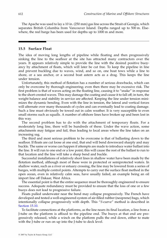
Construction of Marine and Offshore Structures612
The Apache was used to lay a 10 in. (250 mm) gas line across the Strait of Georgia, whichseparates British Columbia from Vancouver Island. Depths ranged up to 500 m. Else-where, the reel barge has been used for depths up to 1000 m and more.
15.5 Surface Float
The idea of moving long lengths of pipeline while floating and then progressivelysinking the line to the seafloor at the site has attracted many contractors over theyears. It appears relatively simple to provide the line with the desired positive buoy-ancy by attachment of floats, which will later be cut free. To keep the pipeline in lineand prevent buckling due to waves, wind, and so on, one boat tows while a line toshore, or a sea anchor, or a second boat astern acts as a drag. This keeps the lineunder tension.
Unfortunately, this method of flotation has a number of serious drawbacks, which canonly be overcome by thorough engineering; even then there may be excessive risk. Thefirst problem is that of waves acting on the floating line, causing it to “snake” in responseto the short-crested waves. This may damage the coating and cause it to fall off; in turn, theweight balance and stability in service are affected. Keeping the line under tension mini-mizes the dynamic bending. Even with the line in tension, the lateral and vertical forceswill alternate over many thousands of cycles and can eventually lead to coating damage.Such a line must obviously be towed out in calm weather. It is very susceptible to evensmall storms such as squalls. A number of offshore lines have broken up and been lost inthis way.
The second problem has to do with the attachment of temporary floats. For amoderately long line, there will be hundreds of these. Under the wave action, someattachments may fatigue and fail, thus leading to local areas where the line takes on anincreasing sag.
The third and most serious problem to be overcome is that of ballasting down to theseafloor. If floats are cut loose at one end, that end will bend downward sharply and maybuckle. The same or worse can happen if attempts are made to introduce water ballast intothe line. It will run to one end or a low point; this will cause the rest of the ballast to run tothat location and the line will take a sharp bend and buckle.
Successful installations of relatively short lines in shallow water have been made by theflotation method, although most of these were in protected or semiprotected waters. Inshallow water, such as a river or estuary crossing, the line may be lowered from a series ofbarges, with multiple control points. Attempts to carry out the surface float method in theopen ocean, even in relatively calm seas, have usually failed, an example being an oilimport line off Dakaar, West Africa.
The essential point is that the entire sequence must be thoroughly engineered to ensuresuccess. Adequate redundancy must be provided to ensure that the loss of one or a fewbuoys does not lead to progressive failure.
Floats pulled underwater near the bend may collapse progressively. The French havedeveloped and tested a well-engineered system of air-filled rubber (neoprene) bags, whichintentionally collapse progressively with depth. This “S-curve” method is described inSection 15.10.
To facilitate connections at the platforms, as the line nears its final location, a line from aJ-tube on the platform is affixed to the pipeline end. The buoys at that end are pro-gressively released, while a winch on the platform pulls the end down, either to matewith the J-tube or run on up into the J-tube to deck level.
q 2007 by Taylor & Francis Group, LLC

Installation of Submarine Pipelines 613
15.6 Controlled Underwater Flotation (Controlled Subsurface Float)
The controlled underwater flotation method has been developed to overcome some of thedeficiencies of the surface flotation method described in Section 15.5. In this method,the pipeline, having slight net negative buoyancy, is towed at a depth of 5 m or sobelow the surface, where it is much less affected by local waves and not at all by wind.
Support for the line is by hinged or articulated spar buoys attached at frequent intervals.These provide a relatively constant upward force, giving a “soft” response, that is, not veryresponsive to the changes in sea level due to short waves. With their small waterline plane,they do not respond significantly to wind-driven waves, and the frequency of response ofthe system becomes very long (over one minute). This system, therefore, virtually elimin-ates the first major problem of flotation.
The line is kept under tension, with one boat towing, another acting as a stern drag.Upon arrival at the site, the line must be lowered to the seafloor. This is done by cutting offevery second spar, by a diver or ROV, while still keeping the line under tension. Of course,when the line is on the seafloor, the remaining spars are also removed.
This method of controlled subsurface float has been successfully used for flow lines andplatform interconnection lines in the North Sea.
15.7 Controlled Above-Bottom Pull
Continued efforts to develop a reliable method for transport and installation of lines haveled to the development of a number of ingenious methods, many of them developed by R.J. Brown. One of these is the “controlled above-bottom pull” method in which the lineitself is designed for slight positive buoyancy. Short lengths of chain are attached atfrequent intervals to give the overall combination negative buoyancy. Thus it is the endof the chain that drags on the seafloor, not the pipe.
The chains automatically control the net underwater weight of the combined system. Ifthe pipeline tends to rise, it lifts more chain off the bottom; if the pipeline tends to sagdown, more chain rides on the bottom, reducing the downward pull on the line.
The friction force is now determined by the weight of the “tails” of the chains, whichdrag on the seafloor. The length of tail is in turn determined by the variations in bathy-metry over a short distance and the safety required to offset tolerances in weight andbuoyancy. While these can be calculated ahead of time, once the pipeline has beenlaunched in relatively shallow water it can be inspected by divers and adjustmentsmade in chain length made before pulling out to deep water.
The attachments of the chain to the pipeline must be properly detailed to preventchafing and abrasion. A weak link may be installed to ensure that should a chain snagon an underwater obstruction, it will break free before buckling or crimping the pipe.
The controlled bottom-pull method has proved cost-effective in installations in theNorth Sea and offshore California, especially for lines of limited length, of the order of3000 m. During tow, at 3–4 knots, the pipeline may “fly” at a depth of 30–40 m below thesurface. As it approaches location and the tow is slowed, it gradually lowers to just abovethe seafloor, with the chains dragging the bottom. Then it is pulled into final position andballasted down onto the seafloor.
A larger-diameter pipeline may be employed as a carrier line for several smaller flowlines and cables bundled inside. Obviously, it is essential that the carrier pipe maintain itswatertight integrity during the tow. Internal pressurization has been utilized to overcome
q 2007 by Taylor & Francis Group, LLC

Construction of Marine and Offshore Structures614
any leakage. Unfortunately, in at least two recent cases, the combined line has prematurelyflooded and sunk, damaging the flow lines being carried inside the carrier pipe. Thiswould indicate that consideration needs to be given to methods of “damage control” ofin-leakage due to possible overstress during tow. Appropriate steps might include use offoam, compressed air, multiple pipes, or subdivision.
The controlled subsurface-pull and controlled above-bottom-pull methods have beencombined by C. G. Doris for bundled lines to constitute what they have named as the“guide rope method” for placing flow line bundles. The bundle assembly includes bothfloats and chains. When the pipeline is empty, it floats 30 m below the surface; when filled,it floats 10 m above the bottom. Thus, it can “fly” over obstacles, rock outcrops, escarp-ments, and other pipelines. Filling produces significant bending in the line. This is bestcontrolled by flooding one line in a bundle at a time.
One such bundle of 4- and 2-in. pipes was towed 13 miles just below the surface, andthen sunk to the above-bottom mode and the ends pulled into subsea manifold connec-tions, using a guide funnel and pull-in lines through sheaves. Cutting the floats allowedthe line to sink to the seafloor.
For installing pipelines between the underwater manifold and the Cormorant A plat-form in the North Sea, an 8-in. oil line plus 2- to 3-in. TFL well test service lines were madeup inside insulated sleeves which in turn were placed within two carrier pipes, one 26-in.line and one 24-in. line. The bundle was then towed in two 3.3-km lengths, kept at mid-depth by the chains for a distance of 490 km using one tug of 75-tn. maximum bollard pullpulling and another of 35-tn. maximum bollard pull restraining, that is, keeping the line intension. The average pulling forces were 50-tn. pull, and 12-tn. restraint, and the averagespeed 5.5 knots. Depth below surface was 30–100 m. Slowing down and reducing thetension allowed the line to submerge to near bottom. When in position and mated, thecarrier pipe was flooded.
The carrier pipes were pressurized with nitrogen gas to 15 atm to prevent waterin-leakage. A full contingency plan was developed to cope with possible accidents ordifficulties, such as the snagging of a chain on an obstruction. The position of the pipesas they approached the field installations was monitored by acoustic transponders andside-scan sonar.
Figure 15.25 illustrates four different versions of pulled lines.
Hold-back vessel
Hold-back vessel
FloatationTow vessel
Cable tow siec
CableTow cable
Hold-back vessel Spar buoyTow vessel
Tow vesselTow vessel
Tow sled
Tow sled
Pipe
Pipe
Bottom towNear-bottom tow
Buoyancy
Chain
Pipe
Pipe
Surface tow Below-surface tow
Floatation Cable
FIGURE 15.25Tow installation methods for installation of flow lines.
q 2007 by Taylor & Francis Group, LLC

Installation of Submarine Pipelines 615
15.8 J-Tube Method from Platform
Curved J-tubes with a “straightener” curve at the exit can be pre-installed on a jacket. Afterthe platform is in place, a messenger line (also pre-installed in the J-tube and temporarilyrun up to stop off at the deck) is connected to a long pulling line from shore or a barge. Thepipeline is made up vertically on the platform, using steel quality and coating similar tothat used for reel barge operations (see Section 15.4). This practice of successive verticaljointing is called stove piping.
The barge or shore winches now pull the end of the line down the J-tube, around thebend, and out over the seafloor as a bottom pull. Thus, the length of line which can bepulled is limited by the friction in the bend and straightener plus the bottom friction.
15.9 J-Lay from Barge
This is the fourth-generation barge, especially designed for deep water. See Chapter 22 forfull description of this method. The pipe departs from the pipe-laying vessel almostvertically, and hence has no overbend. This method utilizes a hinged ramp, inclinedonly slightly from vertical on which a triple- or even quadruple-jointed pipe segment isplaced. The joining of the segments to the previously laid pipe takes place at a singlestation just above deck level. To make acceptable progress, advanced methods for fastautomatic welding are employed. These include electron-beam welding, high-frequencyinduction welding, friction welding, flash-butt welding, high-speed electrical resistanceforge welding (HPW), and laser welding. Mechanical connections have been proposed.The aim is to complete the jointing process in two to three minutes, followed by magneticparticle testing (see Figure 15.26).
The axial tension is largely determined by the weight of the pipe hanging below the laybarge, which reduces the forward-leading tension requirements to where this thrust cannow be applied by dynamic thrusters, and all mooring lines can be eliminated. This in turneliminates the slow-drift accelerations, so that work can proceed in more severe sea states,the limiting factor being that of pipe transfer.
Hingedramp
Tensioner
One or twoforward
leading mooringlins (optional)
Electron-beam orfriction welding,
X-ray, and coating
Triple-jointingof pipe
Helideck
Dynamicthrusters
Catenary sag bendFIGURE 15.26Catenary or “J-curve” method of pipelineinstallation. (Courtesy of Exxon Explora-tion & Production.)
q 2007 by Taylor & Francis Group, LLC
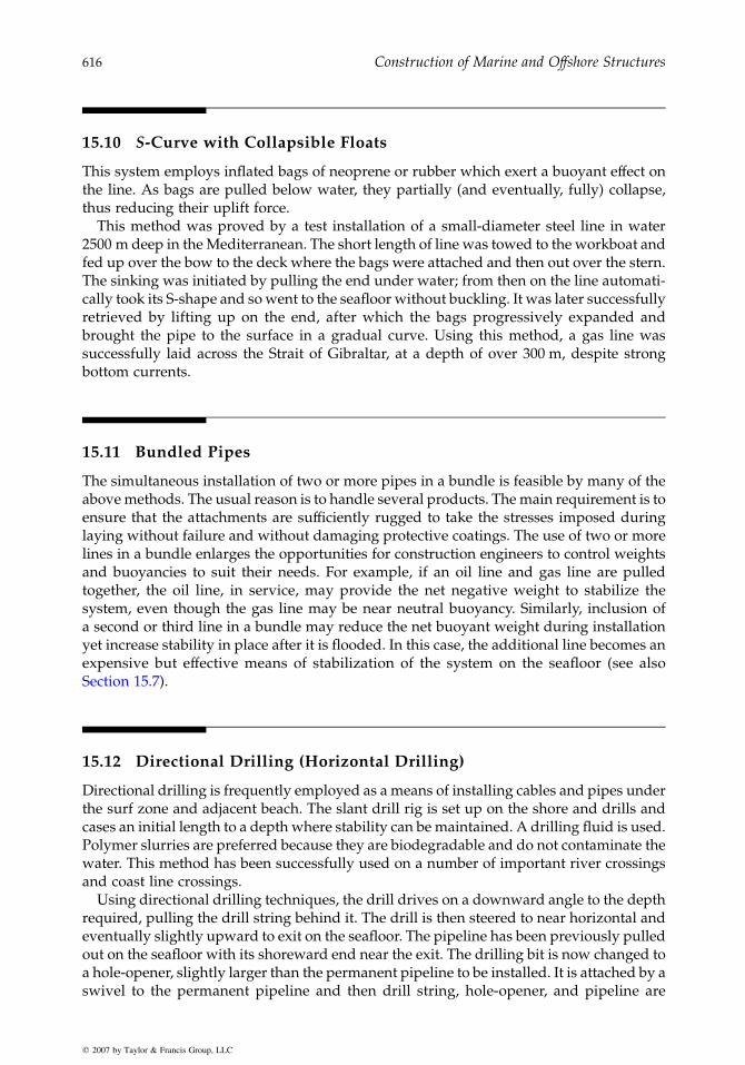
Construction of Marine and Offshore Structures616
15.10 S-Curve with Collapsible Floats
This system employs inflated bags of neoprene or rubber which exert a buoyant effect onthe line. As bags are pulled below water, they partially (and eventually, fully) collapse,thus reducing their uplift force.
This method was proved by a test installation of a small-diameter steel line in water2500 m deep in the Mediterranean. The short length of line was towed to the workboat andfed up over the bow to the deck where the bags were attached and then out over the stern.The sinking was initiated by pulling the end under water; from then on the line automati-cally took its S-shape and so went to the seafloor without buckling. It was later successfullyretrieved by lifting up on the end, after which the bags progressively expanded andbrought the pipe to the surface in a gradual curve. Using this method, a gas line wassuccessfully laid across the Strait of Gibraltar, at a depth of over 300 m, despite strongbottom currents.
15.11 Bundled Pipes
The simultaneous installation of two or more pipes in a bundle is feasible by many of theabove methods. The usual reason is to handle several products. The main requirement is toensure that the attachments are sufficiently rugged to take the stresses imposed duringlaying without failure and without damaging protective coatings. The use of two or morelines in a bundle enlarges the opportunities for construction engineers to control weightsand buoyancies to suit their needs. For example, if an oil line and gas line are pulledtogether, the oil line, in service, may provide the net negative weight to stabilize thesystem, even though the gas line may be near neutral buoyancy. Similarly, inclusion ofa second or third line in a bundle may reduce the net buoyant weight during installationyet increase stability in place after it is flooded. In this case, the additional line becomes anexpensive but effective means of stabilization of the system on the seafloor (see alsoSection 15.7).
15.12 Directional Drilling (Horizontal Drilling)
Directional drilling is frequently employed as a means of installing cables and pipes underthe surf zone and adjacent beach. The slant drill rig is set up on the shore and drills andcases an initial length to a depth where stability can be maintained. A drilling fluid is used.Polymer slurries are preferred because they are biodegradable and do not contaminate thewater. This method has been successfully used on a number of important river crossingsand coast line crossings.
Using directional drilling techniques, the drill drives on a downward angle to the depthrequired, pulling the drill string behind it. The drill is then steered to near horizontal andeventually slightly upward to exit on the seafloor. The pipeline has been previously pulledout on the seafloor with its shoreward end near the exit. The drilling bit is now changed toa hole-opener, slightly larger than the permanent pipeline to be installed. It is attached by aswivel to the permanent pipeline and then drill string, hole-opener, and pipeline are
q 2007 by Taylor & Francis Group, LLC

Installation of Submarine Pipelines 617
pulled back to shore. Variations on this procedure enable the pipe to be pushed from shoreinto the slurry-filled hole, following an oversize bit.
The critical zone for collapse is the seafloor exit, where there is increasingly shallowcover. Hence, the endeavor is to select a point for exit that is in stable material.
A somewhat similar result can be attained by jacking of a pipe tunnel. Usually concretepipe sections are used. The initial thrust is from a jacking pit on shore. The line is laid dry,like a tunnel, with a cutter head, essentially a small Tunnel Boring Machine (TBM) at theface. Polymer slurry may be injected into the annulus at intervals to reduce friction. Whenthe initial jacking force is not sufficient, an intermediate jacking station is established tojack a further length. The line may be steered into a pre-set seaward terminal box, which isessentially a small box caisson, sunk to design grade below the sea. Pipelines are thenpulled through the concrete pipe tunnel.
15.13 Laying Under Ice
To install pipelines below the ice, several variations on the bottom-pull method have beendeveloped. These have assumed that the work would be done in winter and that the icewould be “fast ice,” with little movement over the period involved in the pipe-layingoperations. Initially it is necessary to run a messenger line. Holes can be cut in the ice atintervals along the line and acoustic transponders installed at each. An ROV can then belowered through one hole, and programmed to lay out a messenger line to each holein succession.
The messenger line is then used to pull a wire rope line (the pull line). The pipe is thenmade up on a launching ways and pulled into place by the conventional bottom-pull method.
Prior installation of a larger-diameter pipe under the shoreline through which theprincipal pipeline is to be pulled may be required for permafrost insulation. This casingcan also be used as a means of reducing friction and separating the near-shore excavationand construction from the main pull.
Installation of pipelines in the Arctic is described in more detail in Section 23.16.
15.14 Protection of Pipelines: Burial and Covering with Rock
The burial of pipelines is often required in order to provide protection to the pipelineagainst repetitive pounding under wave action, the impact of dropped anchors, snaggingby trawl boards, and to prevent loss of fishing gear by bottom fishermen. Burial of the pipealso permits the pipe to be designed with less net weight (less coating) which in turnreduces the bending stresses during pipe laying.
The “pounding” referred to above is especially serious in the surf zone, as well as inshallow water where vortex shedding by wave-induced currents can cause alternateraising and lowering of sections of the line, leading to fatigue. Concrete coating can beruptured and break off, allowing the line to rise. The same phenomenon can occur due tohigh currents alone, in locations such as Cook Inlet, Alaska. In the inner portion of the surfzone, the damage may be aggravated by direct wave impact and by abrasion from movingsand and gravel.
q 2007 by Taylor & Francis Group, LLC

Construction of Marine and Offshore Structures618
Burial can be accomplished by laying the line in a predredged trench or by subsequenttrenching after the line is laid. A similar protection may be given to a surface-laid line bycovering it with rock.
Where underwater sand dunes are migrating, as in the southern portion of the EnglishChannel, then predredging by a trailer suction hopper dredge has proved practicable. Theline is predredged to a stable elevation, and then the pipeline is laid.
Through the surf zone, a variety of solutions are employed. At beaches where the surfand longshore currents are relatively mild, a hydraulic dredge may be employed to over-dredge a channel through the beach. The line can then be pulled ashore from the lay barge,allowing the sands to naturally backfill the trench. However, where the beach is subjectedto heavy pounding from storm surf, over a period of time, the iterative raising of the porepressures in the sand may jack the pipe up and out to exposure. Therefore, the pipe mustbe sufficiently heavy in this zone so that in service it remains stable. This may require extrajacketing, the use of the double-pipe concept, pipeline anchors, or high-density backfillover filter fabric. Instances of such raising and exposure are reported from such wide-spread areas as Cook Inlet, Alaska, Ninety-Mile Beach on Bass Strait, Australia, and theStrait of Magellan.
Another method, of course, is the use of a sheet-pile cofferdam through the surf zone,which keeps the trench open while the line is pulled through it. Finally, a tunnel or tubecan be preconstructed through the surf zone. This can be concrete or steel pipe prelaid in acofferdam, a directionally drilled hole with a casing of larger-diameter pipe, or a precastconcrete tube jacked in.
A large, precast concrete submerged tunnel or tube was constructed at Cove Point,Maryland, through which an LNG line was run. Similar precast concrete tube segmentswere installed on the west coast of Norway, on a very exposed rocky coast. The StatpipeGas Line was then pulled through the tunnel.
For burial of pipelines in deeper water, trenching has most often been carried out by a jetsled, designed to be guided by the pipe and to excavate the soil beneath it so that the linewill sink below the seafloor. The jet sled may be designed to run on the pipe, using rubberwheels. The machine must be designed to ensure that its tires cannot damage the coating(see Figure 15.27). In one case in southern California, repeated running of the jet sled overthe line broke up the coating to the extent that the line had to be replaced. Other jet sledsare designed to skid, crawl, or run on the adjoining seabed, being centered and guided bythe pipe but not supported by it. A problem here arises, of course, if the trench side slopesbecome too flat due to encountering loose sediments.
Excavation under the pipe may be accomplished by a combination of jetting, airlift, oreductor removal, or mechanical cutting (see Figure 15.28). The emphasis is on powerfulequipment (see Figure 15.28 through Figure 15.30). It should be able to cut to the requireddepth in one pass. Multiple passes not only are costly, almost in proportion to the numberrequired, but may become less effective due to the increasing depth and progressive infillof the trench.
A steel pipeline has significant bending rigidity and strength. Hence, it will not movedown into a dredged trench unless the dredged length is sufficient to cause it to deflect tothe bottom. Therefore, the trench when cut must stay open long enough to enable the lineto feed itself to the bottom of the trench. Fortunately, this is usually not a problem in mostdeep-water pipeline installations, since bottom currents and sediment infill are usuallylimited over a short period of time in the relatively calm seas in which the operation will becarried out.
Power requirements for jet sleds and trenching machines are high. As much as 32,000HP has been used to power the jets and eductors of a large pipeline burial system used totrench boulder clay in the North Sea. For the pipeline bury barge Creek, eight engines
q 2007 by Taylor & Francis Group, LLC
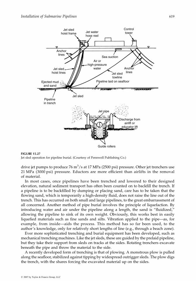
Jet sledhoist frame
Anchorlines
Air orhigh-pressure
water AnchorlinesJet sled
towlinePipeline laid on seafloorEjected mud
and sand
Pipelinein trench
Jet sled
Jet pipe
Guide rollers
Discharge fromairlift or
educator lift
Jet sledhoist lines
Jet waterhose reel
Sea suction
Controltower
FIGURE 15.27Jet sled operation for pipeline burial. (Courtesy of Pennwell Publishing Co.)
Installation of Submarine Pipelines 619
drive jet pumps to produce 76 m3/s at 17 MPa (2500 psi) pressure. Other jet trenchers use21 MPa (3000 psi) pressure. Eductors are more efficient than airlifts in the removalof material.
In most cases, once pipelines have been trenched and lowered to their designedelevation, natural sediment transport has often been counted on to backfill the trench. Ifa pipeline is to be backfilled by dumping or placing sand, care has to be taken that theflowing sand, which is temporarily a high-density fluid, does not raise the line out of thetrench. This has occurred on both small and large pipelines, to the great embarrassment ofall concerned. Another method of pipe burial involves the principle of liquefaction. Byintroducing water and air under the pipeline along a length, the sand is “fluidized,”allowing the pipeline to sink of its own weight. Obviously, this works best in easilyliquefied materials such as fine sands and silts. Vibration applied to the pipe—as, forexample, from inside—aids the process. This method has so far been used, to theauthor’s knowledge, only for relatively short lengths of line (e.g., through a beach zone).
Ever more sophisticated trenching and burial equipment has been developed, such asmechanical trenching machines. Like the jet sleds, these are guided by the prelaid pipeline,but they take their support from sleds on tracks at the sides. Rotating trenchers excavatebeneath the pipe and throw the material to the side.
A recently developed form of trenching is that of plowing. A monstrous plow is pulledalong the seafloor, stabilized against tipping by widespread outrigger sleds. The plow digsthe trench, with the shares forcing the excavated material up on the sides.
q 2007 by Taylor & Francis Group, LLC

FIGURE 15.28Deep-water jet sled employs a two-stage seawatereductor system to excavate trench for pipelineburial.
Construction of Marine and Offshore Structures620
This development was pioneered by R. J. Brown and has proved very successful in thefirm clays of the North Sea. The plows have been designed for the soils expected to beencountered, heavy in North Sea clays, lighter in recent sediments in the Beaufort Sea. Inthe Bass Strait, Australia, an 80-tn. plow was used to post-trench the line, with the plowdesigned to ride along the pipeline. This pipe dug a furrow up to 1.2 m deep in sand andpartially cemented cap rock ledges.
Towing forces generally are one to two times the weight of the plow. Traction isprovided by a large, dynamically positioned towboat for relatively light plows or by anoffshore derrick barge for heavy plows.
One of the most spectacular uses of the plow to date was on the Northwest Shelf ofAustralia, where an enlarged version of the plow weighing 380 tn. trenched a 1- to 2.3-m-deep trench for 118 km of 46-in. (1150 mm) O.D. line in only one month (see Figure 15.31and Figure 15.32). The plow had to dig through limestone and caprock, requiring up to460 tn. pull, whereas in softer materials, sand plus silt and clay, 250-tn. pulling force wassufficient. Plowing rates reported were 15–45 m/min in sand, 10–20 m/min in sand overrock, and 5–10 m/min in limestone. Difficulties arose principally in soft material, wherethe plow dug itself in too deeply.
The plow was pulled by a large offshore pipe-laying barge, using a chain-pulling lineand developing its reaction force from the barge’s anchor lines. The sequence of start-upwas as follows. The two mating (positioning) cones were lowered over the pipeline, beingspaced apart 40 m by a strut. Divers guided them to seat over the pipe on the seafloor. Theplow was now floated to position over the pipe and ballasted down. Removable femalesleeves fitted over the pre-placed mating cones. With the plow now accurately in place, thepipe was pulled up into roller guides at each end. The plowshares were then lowered
q 2007 by Taylor & Francis Group, LLC

12"-36 Pipelien
Discharge pipe
Umbilical cable
FIGURE 15.29Jet sled for pipeline burial. (Courtesy of Toyo Pump Co.)
Installation of Submarine Pipelines 621
hydraulically to meet underneath the pipe, where they were clamped together. Theforward part of the plow rode on two outrigger crawlers, which were Caterpillar D-9tractor underbodies. The derrick barge had hydraulic controls, which enabled it to raiseor lower the plow in relation to the crawlers, thus regulating the depth of cut.
The plow concept uses a long spread between the Cat tractors to automatically even outirregularities on the seafloor. R. J. Brown has suggested that use of computerized controls,reacting to leading sensors, will be developed in the future to handle even rough seafloorprofiles. It is believed that a similar system could be employed to scrape the spoil pilesback into the trench, should early backfill be required.
Plowing appears especially attractive in Arctic soils where lines will have to be trencheddeeply (up to 3 m) in order to protect them from the scour of sea ice pressure ridge keels.For the connection line between the Gullfaks A and Statfjord C platforms, the hardboulder-clay required several passes of the plow. Hydraulically operated grader bladeswere designed to push the spoil banks aside, leaving a flat level surface for the followingpasses of the plow. On the Heimdahl pipeline in the North Sea, the 115-km pipeline waspost-trenched by plow in only 11.5 days. The plow weighed 145 tn. It was deployed ontothe pipeline in 150-m water depth in 19 h. Recovery after completion required 13 h.
q 2007 by Taylor & Francis Group, LLC

FIGURE 15.30Jet sled for pipeline burial uses multiple submersible pumps with agitators. (Courtesy of Toyo Pump Co.)
Construction of Marine and Offshore Structures622
The most recently developed plows have small shares at the leading end, which ride thepreviously installed pipe under sensor control, to clear the pipe for the principal plowingaction of the larger, deeper plow behind.
When caprock or rock outcroppings must be trenched, it is normal first to break them upwith explosives. These can be shaped charges laid on the seafloor or drilled in, using high-pressure jet drills or percussion drills. With caprock it is important not to drill through thehard overlying layers, since then the explosion will take place under the caprock, resultingin it being broken into large slabs only, which are extremely difficult to excavate. Foroverconsolidated silts and in permafrost, high-pressure jet drilling has generally beenfound more effective than rotary or pneumatic drilling for the placement of explosives.
FIGURE 15.31Huge plow used to dig trench for pipeline on Northwest Shelf of Australia. (Courtesy of R.J. Brown.)
q 2007 by Taylor & Francis Group, LLC
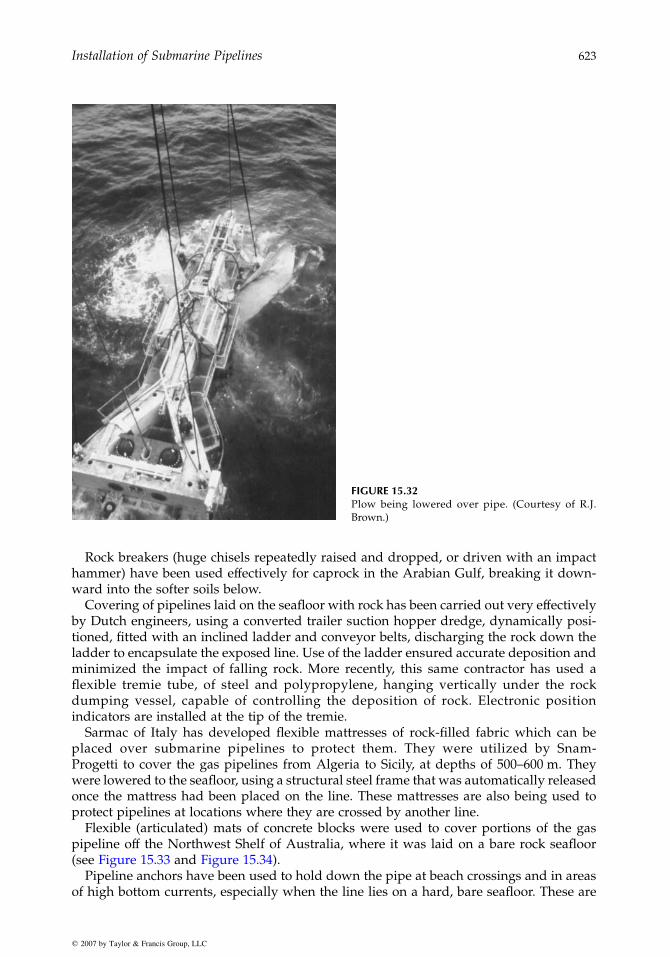
FIGURE 15.32Plow being lowered over pipe. (Courtesy of R.J.Brown.)
Installation of Submarine Pipelines 623
Rock breakers (huge chisels repeatedly raised and dropped, or driven with an impacthammer) have been used effectively for caprock in the Arabian Gulf, breaking it down-ward into the softer soils below.
Covering of pipelines laid on the seafloor with rock has been carried out very effectivelyby Dutch engineers, using a converted trailer suction hopper dredge, dynamically posi-tioned, fitted with an inclined ladder and conveyor belts, discharging the rock down theladder to encapsulate the exposed line. Use of the ladder ensured accurate deposition andminimized the impact of falling rock. More recently, this same contractor has used aflexible tremie tube, of steel and polypropylene, hanging vertically under the rockdumping vessel, capable of controlling the deposition of rock. Electronic positionindicators are installed at the tip of the tremie.
Sarmac of Italy has developed flexible mattresses of rock-filled fabric which can beplaced over submarine pipelines to protect them. They were utilized by Snam-Progetti to cover the gas pipelines from Algeria to Sicily, at depths of 500–600 m. Theywere lowered to the seafloor, using a structural steel frame that was automatically releasedonce the mattress had been placed on the line. These mattresses are also being used toprotect pipelines at locations where they are crossed by another line.
Flexible (articulated) mats of concrete blocks were used to cover portions of the gaspipeline off the Northwest Shelf of Australia, where it was laid on a bare rock seafloor(see Figure 15.33 and Figure 15.34).
Pipeline anchors have been used to hold down the pipe at beach crossings and in areasof high bottom currents, especially when the line lies on a hard, bare seafloor. These are
q 2007 by Taylor & Francis Group, LLC

Heave compensatorsConveyor
Sensor Sensor
Elevatorraise rockto deck
Trollnes
Thrusters
Rock storage
Flexible chute2-m-dia, rings with
polypropelene wires and nets
Transducers enable position tobe continually monitored
Thrusters for dynamic positioning
Jebsens-ACZ
FIGURE 15.33Stone blanket being placed for pipeline protection and stabilization.
Construction of Marine and Offshore Structures624
usually screw anchors, which are drilled into the soil to secure an inverted U-clamp overthe pipe. While these anchors can be installed by divers, this is slow and expensive.Systems have therefore been developed for installing them from a barge directly, usinga frame lowered over the pipeline.
For crossing beach areas where high currents and waves have created a deep layerof cobbles, the protection of the pipeline poses significant difficulties. The use of riprap hasbeen previously described. Heavy-density rock such as iron ore is a possible solution, as wellas double-jacketing with concrete pipe. Horizontal drilling should be considered.
15.15 Support of Pipelines
When laying pipelines across an uneven seafloor of hard material, such as an area of rockoutcrops, it may become necessary to provide supports to prevent excessive sag momentsin the pipeline span. In shallow water, sandbags and grout-filled bags have been stacked inby divers. Burlap bags, half filled with fresh concrete mix of low slump, are best, becausethe grout exuding through the burlap mesh will knit the adjoining bags together. In deeperand more exposed waters, neoprene and flexible fabric bags can be placed by divers andpumped full of grout.
q 2007 by Taylor & Francis Group, LLC

FIGURE 15.34Articulated concrete mat for pipeline protection and stabilization.
Installation of Submarine Pipelines 625
The 520-mile Statpipe Ormen-Lange gas-gathering system, crossing the NorwegianTrench, in depths up to 1000 m with steep rock escarpments, resulted in free spans upto 100 m. In addition to grout bags, steel support frames were designed to give intermedi-ate support to the pipe. An underwater bridge was used to support the pipe in waters ofmoderate depth. To excavate a trench, bottom-crawling “spiders” were used. These werecontrolled by computer systems utilizing 3D terrain models. These employed smallbuckets to dig the trench and sidepost the spoil.
15.16 Cryogenic Pipelines for LNG and LPG
For submarine pipelines to transport LNG and LPG, current technology uses INVAR (36%nickel steel) and low-pressure or vacuum systems for insulation. Recently, a new systemhas been developed using 9% nickel steel product line and high efficiency micro-porous ornano-porous insulating materials, contained within a carbon steel outer jacket and separ-ated by non-metallic bulkheads. This system was used for butane and propane lines to amarine terminal at Pisco, Peru.
q 2007 b
Eternal Father, strong to saveWhose hand doth still the mighty wave
Who bids the restless ocean deepIts own appointed limits keep;
O hear us when we cry to TheeFor those in peril on the Sea.
William Whiting, Hymn of the U.S. Navy
y Taylor & Francis Group, LLC

Related Documents