1 4005484-09 © Copyright Miles Industries Ltd., 2018. LDK HeatShift Kits (LDK1, LDK2, LDK3, LDK4, LDK5, LDK6 & LDK7) CSA approved for use with the following Valor Heater Models ONLY: Optional with 1100J, 1150J, 1400J, 1400K, 1500J, 1600J, 1700J & 1800J MANDATORY on all 2200 LX2 Models Note: This kit must be installed by a qualified installer, service agency or gas supplier at the time of the heater installation. These instructions are to be used in conjunction with the fireplace main installation instructions. INSTALLER: Leave this manual with the appliance. CONSUMER: Retain this manual for future reference. Application This convection duct kit redistributes the warm air flow away from the fireplace opening to a more desirable location using natural convection without use of a fan. LKD1, LDK3 or LDK4: the warm air flow is relocated to a position higher up the wall, out the sidewalls, or even to an adjacent room. LDK7: the warm air flow is discharged through a gap (min. 2-1/2”) between the wall above the fireplace and the ceiling. LDK7’s discharge opening must be located in the same room as the fireplace. The result is much cooler wall temperatures above the fireplace opening for locating televisions, artwork, etc. The 1195CFK and 1595CFK Circulating Fan Kit are not recommended when installing the LDK Duct Kit. Any kit, LDK1, LDK3, LDK4 or LDK7 may be used with any of the model fireplaces listed above. As a further option, the warm airflow may be extracted away from the duct kit plenum (LDK1 and LDK4 ONLY) by connecting a 1270RBK Remote Blower Kit to the duct kit plenum. This kit is compatible with the listed fireplaces only. Earlier version fireplaces will not accept the addition of this kit. Note: These instructions are to be used in conjunction with instructions supplied with the fireplace. Note: All fireplaces listed, except 2200 LX2 models, require the removal of the internal convection baffle for this system to function properly—read instructions carefully. For some models, the use of this kit will permit lower mantel clearances to be used—see pages 15–16. These lower mantel clearances must only be used when the LDK Duct system is installed and the internal convection baffle has been removed. Approvals The LDK1, LDK3, LDK4 and LDK7 duct kits are CSA approved for use only with Valor Series fireplaces listed above—DO NOT use with any other models. This HeatShift system may also be used to reduce wall surface temperatures on approved outdoor installations. 5-inch diameter duct used with this kit must be metal and meet requirements of UL-181 Class 1 Air Duct. Flexible aluminum duct is acceptable provided it meets the UL-181 Class 1 requirements. Kits There are 4 kits to choose from: • LDK1—48” Plenum • LDK3—14” Plenums (2), includes grilles • LDK4—38” Plenum • LDK7—Duct Termination Plates (2)—for wall valance discharge ONLY Optional accessories • LDK2—48” Finishing Frame, to use with LDK1 • LDK5—38” Finishing Frame, to use with LDK4 • LDK6— 5” dia Aluminum 2-ply Flex Kit— 2 x 10’–0” lengths, may be cut to required length WARNING DO NOT cover or place objects in front of or on top of air outlet(s). AVOID locating outlet within 7 feet above fl oor level as discharge temperatures are hot! WARNING Note, when placing discharge close to ceilings, that staining or streaking may occur on light colored ceilings due to any dust, etc. in air flow; placing the plenum(s) lower on the wall will help reduce the possibility of staining or streaking. ! ! ! INSTALLATION MANUAL HeatShift

Welcome message from author
This document is posted to help you gain knowledge. Please leave a comment to let me know what you think about it! Share it to your friends and learn new things together.
Transcript

14005484-09© Copyright Miles Industries Ltd., 2018.
LDK HeatShift Kits (LDK1, LDK2, LDK3, LDK4, LDK5, LDK6 & LDK7)CSA approved for use with the following Valor Heater Models ONLY: Optional with 1100J, 1150J, 1400J, 1400K, 1500J, 1600J, 1700J & 1800JMANDATORY on all 2200 LX2 ModelsNote: This kit must be installed by a qualifi ed installer, service agency or gas supplier at the time of the heater installation. These instructions are to be used in conjunction with the fi replace main installation instructions.INSTALLER: Leave this manual with the appliance.CONSUMER: Retain this manual for future reference.
ApplicationThis convection duct kit redistributes the warm air fl ow away from the fi replace opening to a more desirable location using natural convection without use of a fan. LKD1, LDK3 or LDK4: the warm air fl ow is relocated to a position higher up the wall, out the sidewalls, or even to an adjacent room. LDK7: the warm air fl ow is discharged through a gap (min. 2-1/2”) between the wall above the fi replace and the ceiling. LDK7’s discharge opening must be located in the same room as the fi replace.The result is much cooler wall temperatures above the fi replace opening for locating televisions, artwork, etc. The 1195CFK and 1595CFK Circulating Fan Kit are not recommended when installing the LDK Duct Kit.Any kit, LDK1, LDK3, LDK4 or LDK7 may be used with any of the model fi replaces listed above.As a further option, the warm airfl ow may be extracted away from the duct kit plenum (LDK1 and LDK4 ONLY) by connecting a 1270RBK Remote Blower Kit to the duct kit plenum.This kit is compatible with the listed fi replaces only. Earlier version fi replaces will not accept the addition of this kit.Note: These instructions are to be used in conjunction with instructions supplied with the fi replace.
Note: All fi replaces listed, except 2200 LX2 models, require the removal of the internal convection baffl e for this system to function properly—read instructions carefully.
For some models, the use of this kit will permit lower mantel clearances to be used—see pages 15–16. These lower mantel clearances must only be used when the LDK Duct system is installed and the internal convection baffl e has been removed.
ApprovalsThe LDK1, LDK3, LDK4 and LDK7 duct kits are CSA approved for use only with Valor Series fi replaces listed above—DO NOT use with any other models.This HeatShift system may also be used to reduce wall surface temperatures on approved outdoor installations.5-inch diameter duct used with this kit must be metal and meet requirements of UL-181 Class 1 Air Duct. Flexible aluminum duct is acceptable provided it meets the UL-181 Class 1 requirements.
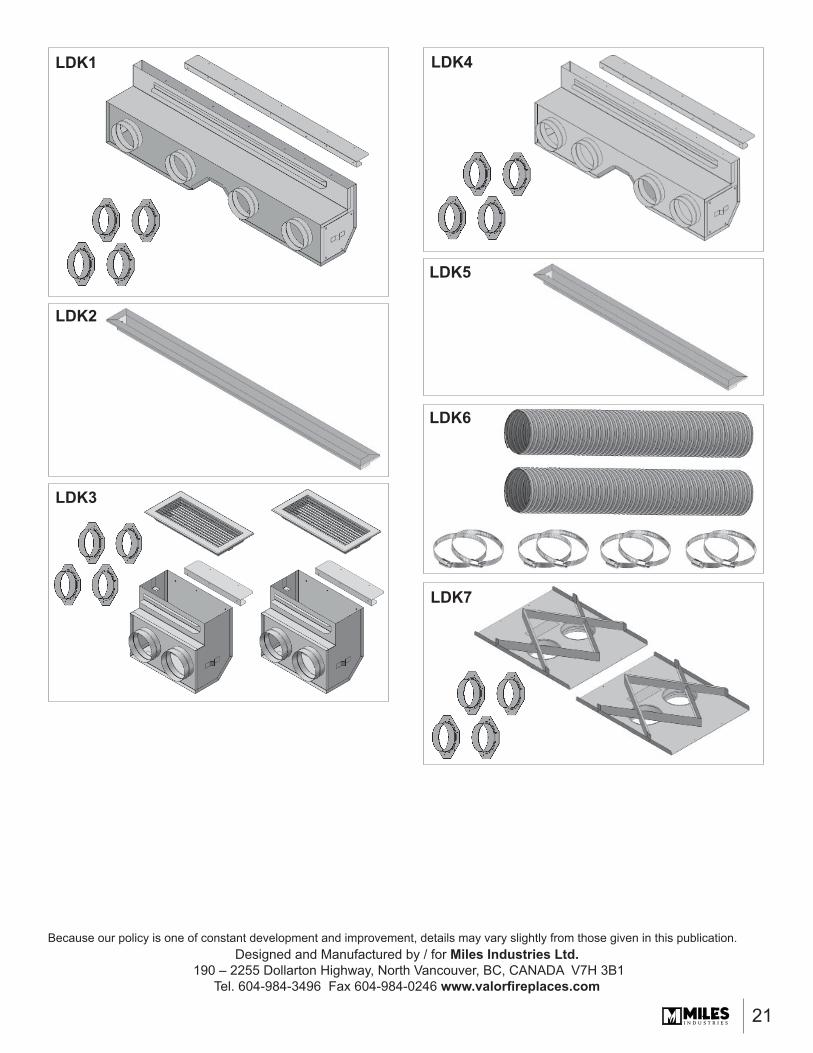
KitsThere are 4 kits to choose from:• LDK1—48” Plenum• LDK3—14” Plenums (2), includes grilles• LDK4—38” Plenum• LDK7—Duct Termination Plates (2)—for wall valance
discharge ONLYOptional accessories• LDK2—48” Finishing Frame, to use with LDK1• LDK5—38” Finishing Frame, to use with LDK4• LDK6— 5” dia Aluminum 2-ply Flex Kit—
2 x 10’–0” lengths, may be cut to required length
WARNINGDO NOT cover or place objects in front of or on top of air outlet(s). AVOID locating outlet within 7 feet above fl oor level as discharge temperatures are hot!
WARNINGNote, when placing discharge close to ceilings, that staining or streaking may occur on light colored ceilings due to any dust, etc. in air fl ow; placing the plenum(s) lower on the wall will help reduce the possibility of staining or streaking.
!
!!
INSTALLATION MANUAL
HeatShift

2
3-5/8”(92 mm)
3-5/8”(92 mm)
7-3/4”(197 mm)
LDK148” x 2”
LDK438” x 2”
LDK32 - 14” x 6”
LDK62 - 10’ x 5” (aluminum fl ex)
LDK5 (supplied separately)38” frame, white
2 - 14” x 6” grilles included, white
4 take-off collars included
4 take-off collars included
4 take-off collars included
LDK2 (supplied separately)48” frame, white
Kits Contents
39-5/8” (1007 mm)
15-3/4” (400 mm)
49-5/8” (1261 mm)
LDK72 Duct termination plates
4 take-off collars included
3
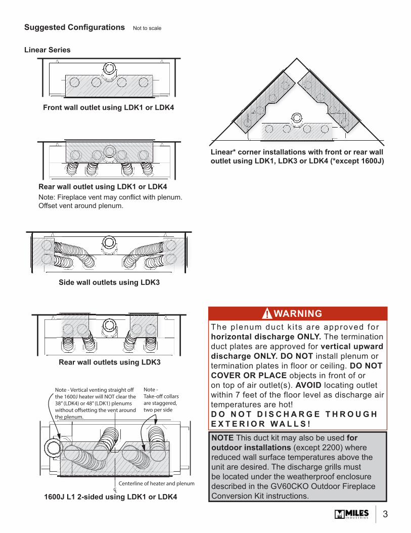
Suggested Confi gurations
Front wall outlet using LDK1 or LDK4
Rear wall outlet using LDK1 or LDK4Note: Fireplace vent may confl ict with plenum. Off set vent around plenum.
Linear* corner installations with front or rear wall outlet using LDK1, LDK3 or LDK4 (*except 1600J)
Side wall outlets using LDK3
1600J L1 2-sided using LDK1 or LDK4CL
Note - Vertical venting straight off the 1600J heater will NOT clear the 38” (LDK4) or 48” (LDK1) plenums without offsetting the vent around the plenum.
Note - Take-off collars are staggered, two per side
Centerline of heater and plenum
WARNINGThe p lenum duct k i ts are approved for horizontal discharge ONLY. The termination duct plates are approved for vertical upward discharge ONLY. DO NOT install plenum or termination plates in floor or ceiling. DO NOT COVER OR PLACE objects in front of or on top of air outlet(s). AVOID locating outlet within 7 feet of the floor level as discharge air temperatures are hot!D O N O T D I S C H A R G E T H R O U G H E X T E R I O R W A L L S !
!
Not to scale
NOTE This duct kit may also be used for outdoor installations (except 2200) where reduced wall surface temperatures above the unit are desired. The discharge grills must be located under the weatherproof enclosure described in the GV60CKO Outdoor Fireplace Conversion Kit instructions.
Rear wall outlets using LDK3
Linear Series
4
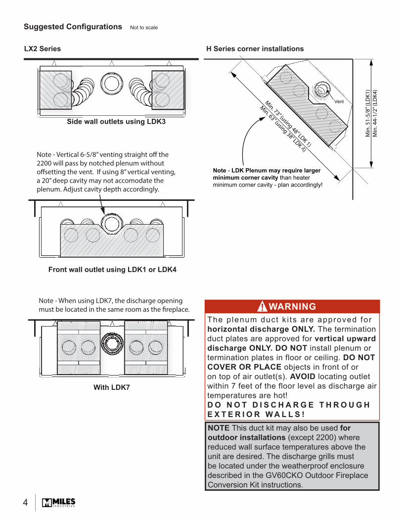
Min. 73” (using 48” LDK 1)
Min. 63” (using 38” LDK 4)
Min
. 51-
5/8”
(LD
K1)
Min
. 44-
1/2”
(LD
K4)
Min. 73” (using 48” LDK 1)
Min. 63” (using 38” LDK 4)
Note - LDK Plenum may require largerminimum corner cavity than heaterminimum corner cavity - plan accordingly!
Vent
H Series corner installations
Suggested Confi gurations Not to scale
Note - Vertical 6-5/8” venting straight off the 2200 will pass by notched plenum without offsetting the vent. If using 8” vertical venting, a 20” deep cavity may not accomodate the plenum. Adjust cavity depth accordingly.
Side wall outlets using LDK3
Front wall outlet using LDK1 or LDK4
LX2 Series
WARNINGThe p lenum duct k i ts are approved for horizontal discharge ONLY. The termination duct plates are approved for vertical upward discharge ONLY. DO NOT install plenum or termination plates in floor or ceiling. DO NOT COVER OR PLACE objects in front of or on top of air outlet(s). AVOID locating outlet within 7 feet of the floor level as discharge air temperatures are hot!D O N O T D I S C H A R G E T H R O U G H E X T E R I O R W A L L S !
!
NOTE This duct kit may also be used for outdoor installations (except 2200) where reduced wall surface temperatures above the unit are desired. The discharge grills must be located under the weatherproof enclosure described in the GV60CKO Outdoor Fireplace Conversion Kit instructions.
Note - When using LDK7, the discharge opening must be located in the same room as the fireplace.
With LDK7
5
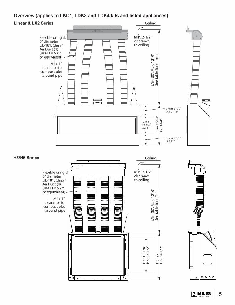
Overview (applies to LKD1, LDK3 and LDK4 kits and listed appliances)
Flexible or rigid,5” diameterUL-181, Class 1Air Duct (4)(use LDK6 kitor equivalent)
Min. 2-1/2” clearanceto ceiling
Min
. 30”
, Max
. 12’
-0”
See
tabl
e fo
r offs
ets
Line
ar 3
2-3/
8”LX
2 33
-1/4
”
Linear 8-1/2”LX2 5-1/4”
Linear14-1/2”LX2 17”
Linear 9-3/8”LX2 11”
Ceiling
Min. 1” clearance to
combustiblesaround pipe
Flexible or rigid,5” diameterUL-181, Class 1Air Duct (4)(use LDK6 kitor equivalent)
Min. 2-1/2” clearanceto ceiling
Min
. 30”
, Max
. 12’
-0”
See
tabl
e fo
r offs
ets
H5:
29”
H6:
34-
1/2”
H5:
19-
1/4”
H6:
25-
1/2”
Ceiling
Min. 1” clearance to
combustiblesaround pipe
Linear & LX2 Series
H5/H6 Series
6
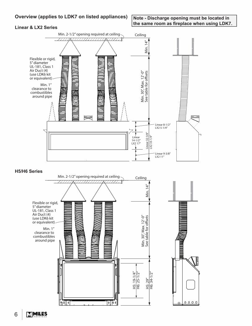
Overview (applies to LDK7 on listed appliances)
Flexible or rigid,5” diameterUL-181, Class 1Air Duct (4)(use LDK6 kitor equivalent)
Min. 2-1/2” opening required at ceiling
Min. 2-1/2” opening required at ceiling
Min
. 30”
, Max
. 12’
-0”
See
tabl
e fo
r offs
ets
Min
. 14”
Min
. 14”
Line
ar 3
2-3/
8”LX
2 33
-1/4
”
Linear 8-1/2”LX2 5-1/4”
Linear14-1/2”LX2 17”
Linear 9-3/8”LX2 11”
Ceiling
Min. 1” clearance to
combustiblesaround pipe
Flexible or rigid,5” diameterUL-181, Class 1Air Duct (4)(use LDK6 kitor equivalent)
Min
. 30”
, Max
. 12’
-0”
See
tabl
e fo
r offs
ets
H5:
29”
H6:
34-
1/2”
H5:
19-
1/4”
H6:
25-
1/2”
Ceiling
Min. 1” clearance to
combustiblesaround pipe
Linear & LX2 Series
H5/H6 Series
Note - Discharge opening must be located in the same room as fi replace when using LDK7.
7
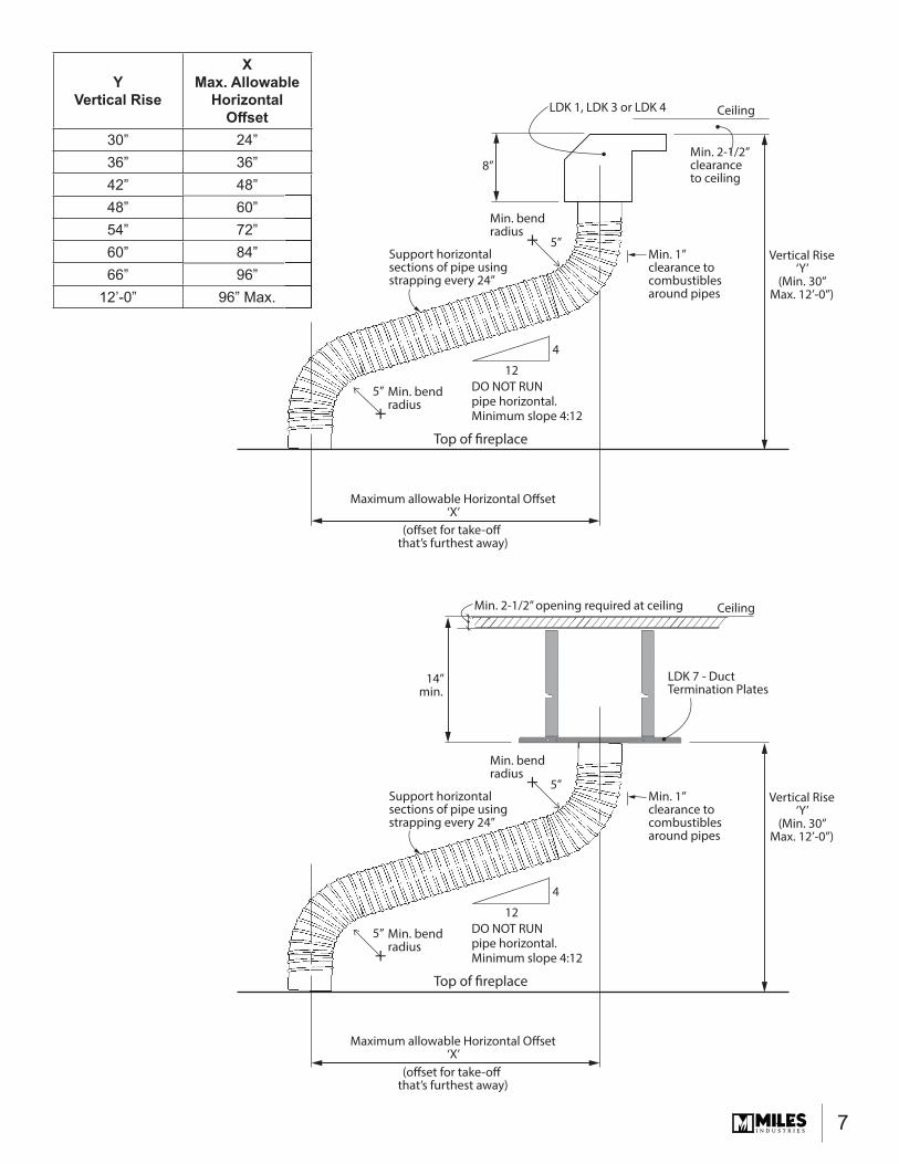
YVertical Rise
XMax. Allowable
Horizontal Off set
30” 24”36” 36”42” 48”48” 60”54” 72”60” 84”66” 96”
12’-0” 96” Max.
Min. 2-1/2” clearanceto ceiling
Min. 1” clearance to combustiblesaround pipes
Support horizontal sections of pipe using strapping every 24”
DO NOT RUN pipe horizontal.Minimum slope 4:12
Min. bendradius
8”
5”
5”
4
12
Vertical Rise‘Y’
(Min. 30”Max. 12’-0”)
Maximum allowable Horizontal Offset‘X’
(offset for take-off that’s furthest away)
CeilingLDK 1, LDK 3 or LDK 4
+
Min. bendradius+
Top of fireplace
Min. 1” clearance to combustiblesaround pipes
Support horizontal sections of pipe using strapping every 24”
DO NOT RUN pipe horizontal.Minimum slope 4:12
Min. bendradius
14”min.
5”
5”
4
12
Vertical Rise‘Y’
(Min. 30”Max. 12’-0”)
Maximum allowable Horizontal Offset‘X’
(offset for take-off that’s furthest away)
LDK 7 - Duct Termination Plates
+
Min. bendradius+
Top of fireplace
CeilingMin. 2-1/2” opening required at ceiling
8
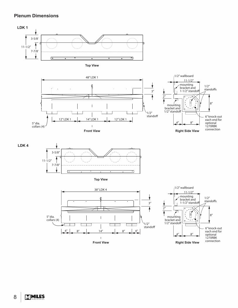
Plenum Dimensions
48” LDK 1
LDK 1
5” dia.collars (4)
CL
12” LDK 1 14” LDK 1 12” LDK 1
2”
8”
1/2”standoffs
6” knock-outeach end foroptional 1270RBKconnection
11-1/2”
8”4”
1/2” wallboard
mounting bracket and 1-1/2” standoff
mounting bracket and 1/2” standoff
3”
1/2”standoff
3-5/8”
7-7/8”11-1/2”
Top View
Front View Right Side View
LDK 4
38” LDK 4
5” dia.collars (4)
CL
8” 14” 8” 4”4”
3”
3-5/8”
7-7/8”11-1/2”
1/2”standoff
Front View
Top View
2”
8”
1/2”standoffs
6” knock-outeach end foroptional 1270RBKconnection
11-1/2”
8”4”
1/2” wallboard
mounting bracket and 1-1/2” standoff
mounting bracket and 1/2” standoff
Right Side View
9
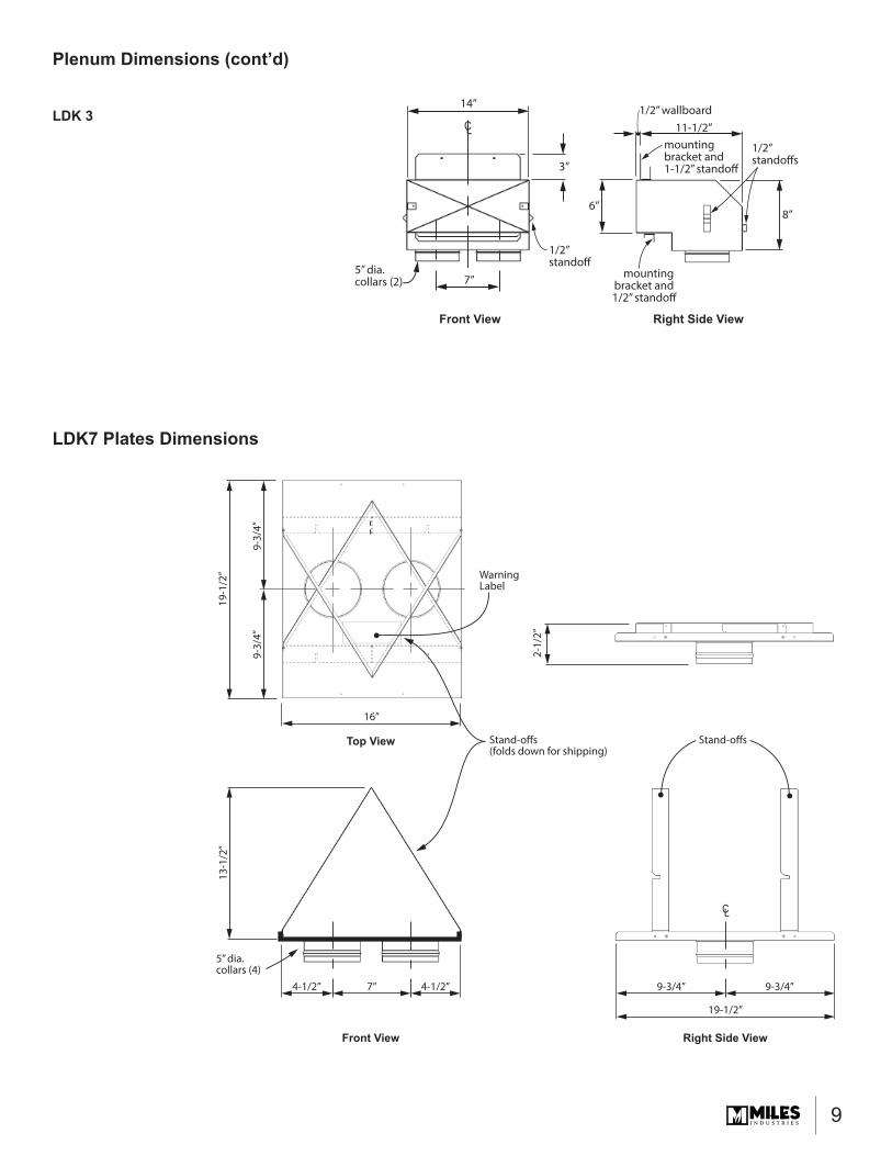
Plenum Dimensions (cont’d)
LDK7 Plates Dimensions
5” dia.collars (4)
CL
7” 4-1/2” 9-3/4” 9-3/4”4-1/2”
19-1
/2”
2-1/
2”
13-1
/2”
16”
19-1/2”
9-3/
4”9-
3/4”
Stand-offs(folds down for shipping)
WarningLabel
Stand-offs
Front View
Top View
Right Side View
LDK 314”
CL
7”
6”
5” dia.collars (2)
3”
mounting bracket and 1-1/2” standoff
mounting bracket and 1/2” standoff
8”
11-1/2”1/2” wallboard
1/2”standoffs
Front View Right Side View
1/2”standoff
10
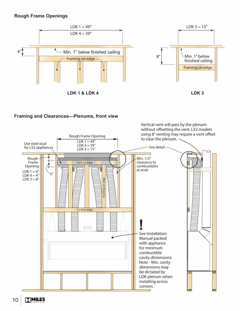
Rough Frame Openings
Min. 1” below finished ceiling
LDK 1 = 49”LDK 4 = 39”
LDK 1 & LDK 4 LDK 3
LDK 3 = 15”
4”
Framing on edge
Framing on edge
Min. 1” below finished ceiling8”
Rough Frame Opening
Rough Frame
Opening
See InstallationManual packedwith appliancefor minimumcombustiblecavity dimensionsNote - Min. cavitydimensions maybe dictated by LDK plenum wheninstalling acrosscorners.
Min. 1/2”clearance tocombustiblesat ends
Use steel studfor LX2 appliances See detail
LDK 1 = 49”LDK 4 = 39”LDK 3 = 15”
LDK 1 = 4”LDK 4 = 4”LDK 3 = 8”
2 x 4 on edge
2 x 4 on edge
Fram
ing
on e
dge
5”
Vertical vent will pass by the plenum without offsetting the vent. LX2 models using 8” venting may require a vent offsetto clear the plenum.
Framing and Clearances—Plenums, front view
!
11
4”8”
LDK 1 & 4
LDK 3
Framing“on edge”
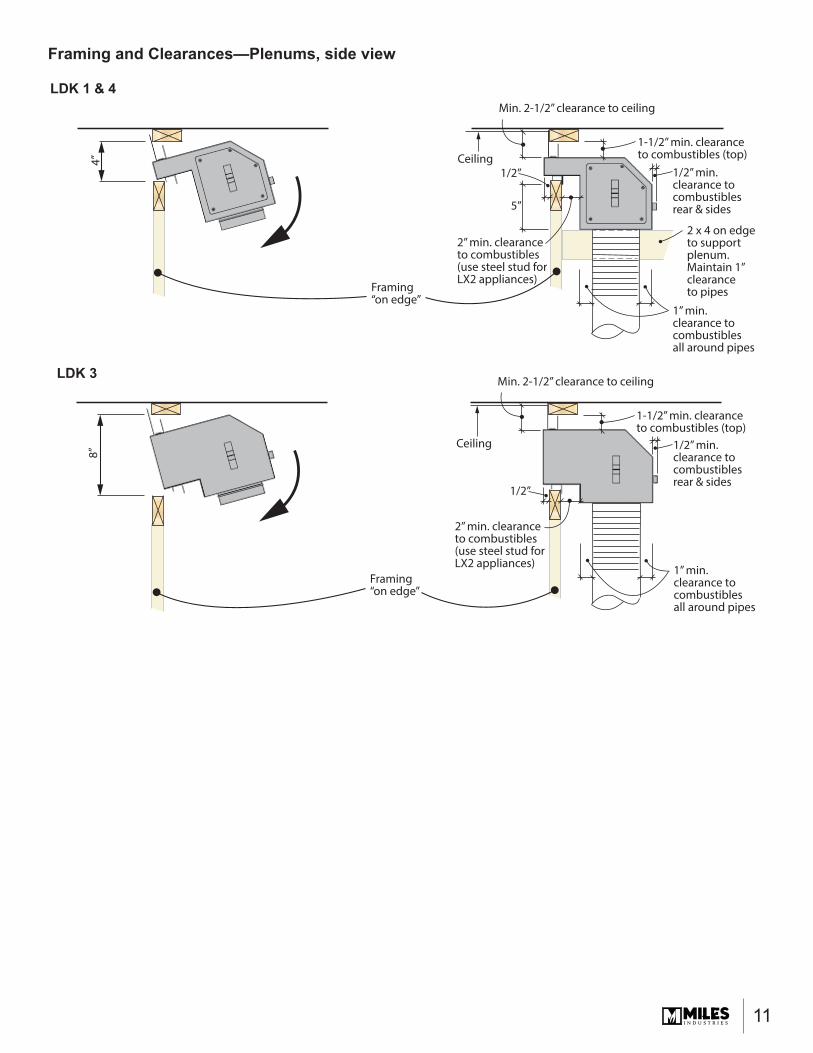
1-1/2” min. clearanceto combustibles (top)
2” min. clearanceto combustibles (use steel stud forLX2 appliances)
2” min. clearanceto combustibles (use steel stud forLX2 appliances)
Ceiling
Min. 2-1/2” clearance to ceiling
1/2”
5”
1/2” min.clearance tocombustiblesrear & sides
1” min.clearance tocombustiblesall around pipes
2 x 4 on edgeto support plenum.Maintain 1”clearance to pipes
Framing“on edge”
1-1/2” min. clearanceto combustibles (top)
Ceiling
Min. 2-1/2” clearance to ceiling
1/2”
1/2” min.clearance tocombustiblesrear & sides
1” min.clearance tocombustiblesall around pipes
Framing and Clearances—Plenums, side view
12
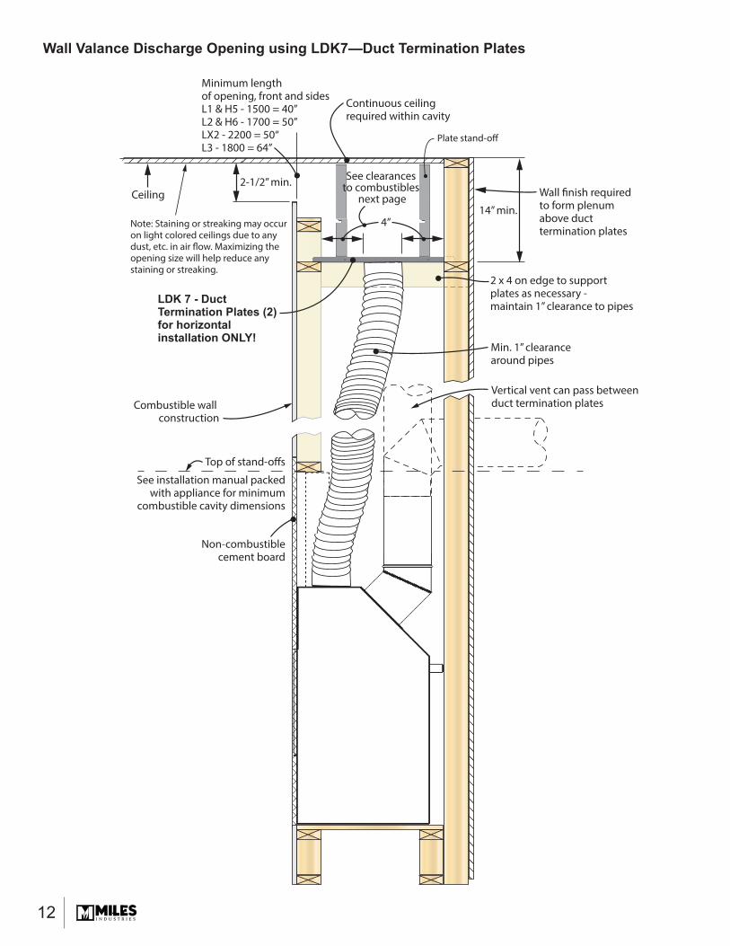
Ceiling2-1/2” min.
4”
See clearances to combustibles
next page14” min.
Minimum length of opening, front and sidesL1 & H5 - 1500 = 40”L2 & H6 - 1700 = 50”LX2 - 2200 = 50“L3 - 1800 = 64”
Combustible wall construction
Top of stand-offs
See installation manual packedwith appliance for minimum
combustible cavity dimensions
Non-combustiblecement board
Min. 1” clearance around pipes
2 x 4 on edge to supportplates as necessary - maintain 1” clearance to pipes
Wall finish required to form plenum above duct termination plates
LDK 7 - Duct Termination Plates (2)for horizontalinstallation ONLY!
Continuous ceiling required within cavity
Note: Staining or streaking may occuron light colored ceilings due to anydust, etc. in air flow. Maximizing the opening size will help reduce anystaining or streaking.
Plate stand-off
Vertical vent can pass between duct termination plates
Wall Valance Discharge Opening using LDK7—Duct Termination Plates

13
LDK7 Clearances to Combustibles
4”4”
4”4” 4”4”
13-1
/2”
19-1
/2”
16”
13-1
/2”
4”4”
Stand-off
Non-combustible zone above plates
Perimeter of plates may be trimmed to suit installation
Combustible framingallowed below plates
5” dia. pipes -maintain 1” clearance
to combustible materials
Front View
Top View
Right Side View
Stand-off
Stand-offs

14
LDK Duct Kit LDK 1, LDK 4 with optional 1270RBK Remote Blower Kit(not approved with outdoor installations)
LDK1 or LDK4 plenum
H5 1100J & 1150J; H6 1400J, 1400K; Linear 1500J, 1600J, 1700J, 1800J and LX2 2200J fireplaces
See installation instructions packagedwith the LDK Duct Kits
Universal take-off supplied with 1270RBK kit. Can mount to either end of plenum.Maximum 1 x 1270RBK kit per plenum.Note: DO NOT CONNECT 1270RBK directlyto fireplace when using LDK Duct Kit; connect to LDK plenum ONLY as this willensure cooler wall temperature whether ornot the 1270 fan is running.
1270RBK fan unit -see diagram for possible mounting positions. May be positioned higheror lower than LDK plenum position.
5” dia. piping
15
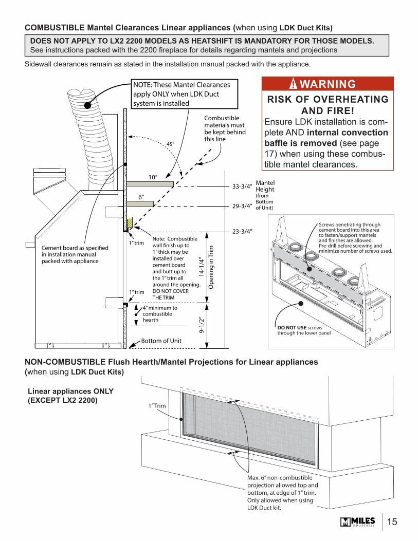
Sidewall clearances remain as stated in the installation manual packed with the appliance.
COMBUSTIBLE Mantel Clearances Linear appliances (when using LDK Duct Kits)DOES NOT APPLY TO LX2 2200 MODELS AS HEATSHIFT IS MANDATORY FOR THOSE MODELS. See instructions packed with the 2200 fi replace for details regarding mantels and projections
NON-COMBUSTIBLE Flush Hearth/Mantel Projections for Linear appliances (when using LDK Duct Kits)
Linear appliances ONLY (EXCEPT LX2 2200)
Bottom of Unit
6”
10”
14-1
/4”
Ope
ning
in T
rim9-
1/2”
Note: Combustiblewall finish up to 1” thick may be installed over cement board and butt up to the 1” trim all around the opening. DO NOT COVER THE TRIM
Cement board as specified in installation manual packed with appliance
1” trim
1” trim
4” minimum to combustible hearth
Combustible materials must be kept behindthis line
23-3/4”
29-3/4”
33-3/4”
45°
NOTE: These Mantel Clearancesapply ONLY when LDK Duct system is installed
MantelHeight(fromBottomof Unit)
Max. 6” non-combustibleprojection allowed top andbottom, at edge of 1” trim.Only allowed when usingLDK Duct kit.
1” Trim
Screws penetrating throughcement board into this areato fasten/support mantelsand finishes are allowed.Pre-drill before screwing andminimize number of screws used.
DO NOT USE screws through the lower panel
WARNINGRISK OF OVERHEATING
AND FIRE! Ensure LDK installation is com-plete AND internal convection baffl e is removed (see page 17) when using these combus-tible mantel clearances.
!
16
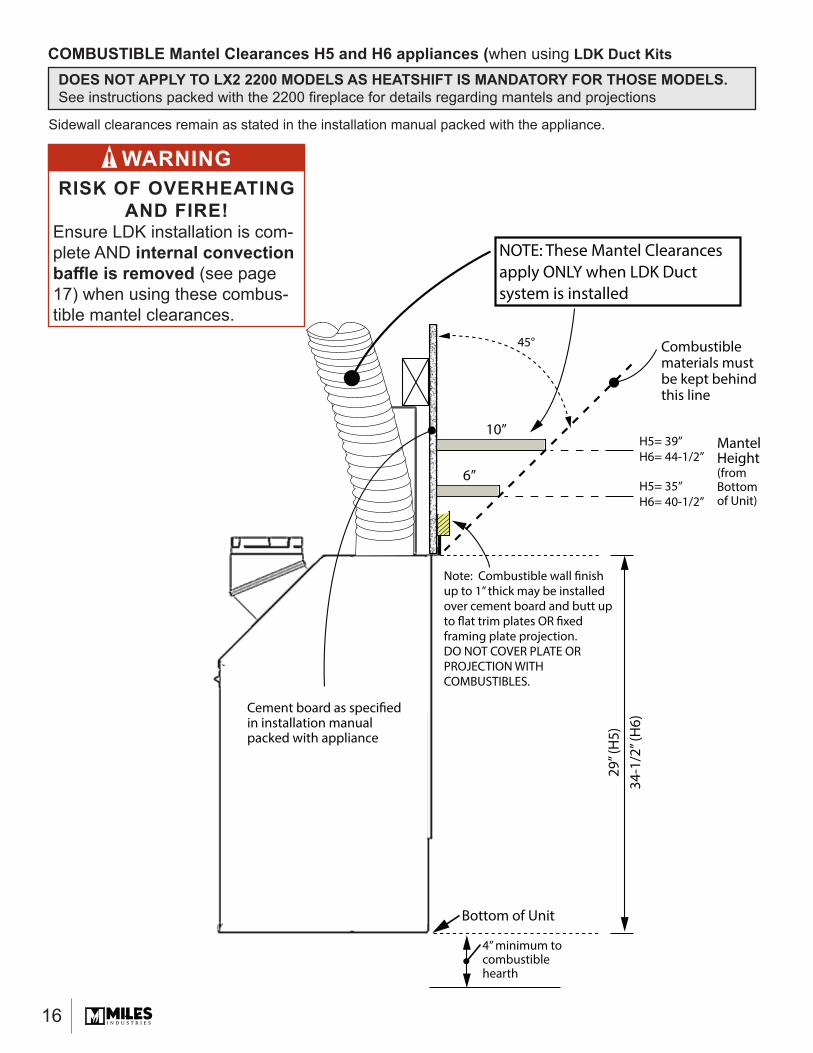
Sidewall clearances remain as stated in the installation manual packed with the appliance.
Bottom of Unit
6”
10”
29” (
H5)
34-1
/2” (
H6)
Note: Combustible wall finish up to 1” thick may be installed over cement board and butt up to flat trim plates OR fixed framing plate projection. DO NOT COVER PLATE OR PROJECTION WITH COMBUSTIBLES.
Cement board as specified in installation manual packed with appliance
Combustible materials must be kept behindthis line
45°
NOTE: These Mantel Clearancesapply ONLY when LDK Duct system is installed
MantelHeight(fromBottomof Unit)
4” minimum to combustible hearth
H5= 35”H6= 40-1/2”
H5= 39”H6= 44-1/2”
WARNINGRISK OF OVERHEATING
AND FIRE! Ensure LDK installation is com-plete AND internal convection baffl e is removed (see page 17) when using these combus-tible mantel clearances.
!
COMBUSTIBLE Mantel Clearances H5 and H6 appliances (when using LDK Duct KitsDOES NOT APPLY TO LX2 2200 MODELS AS HEATSHIFT IS MANDATORY FOR THOSE MODELS. See instructions packed with the 2200 fi replace for details regarding mantels and projections
17
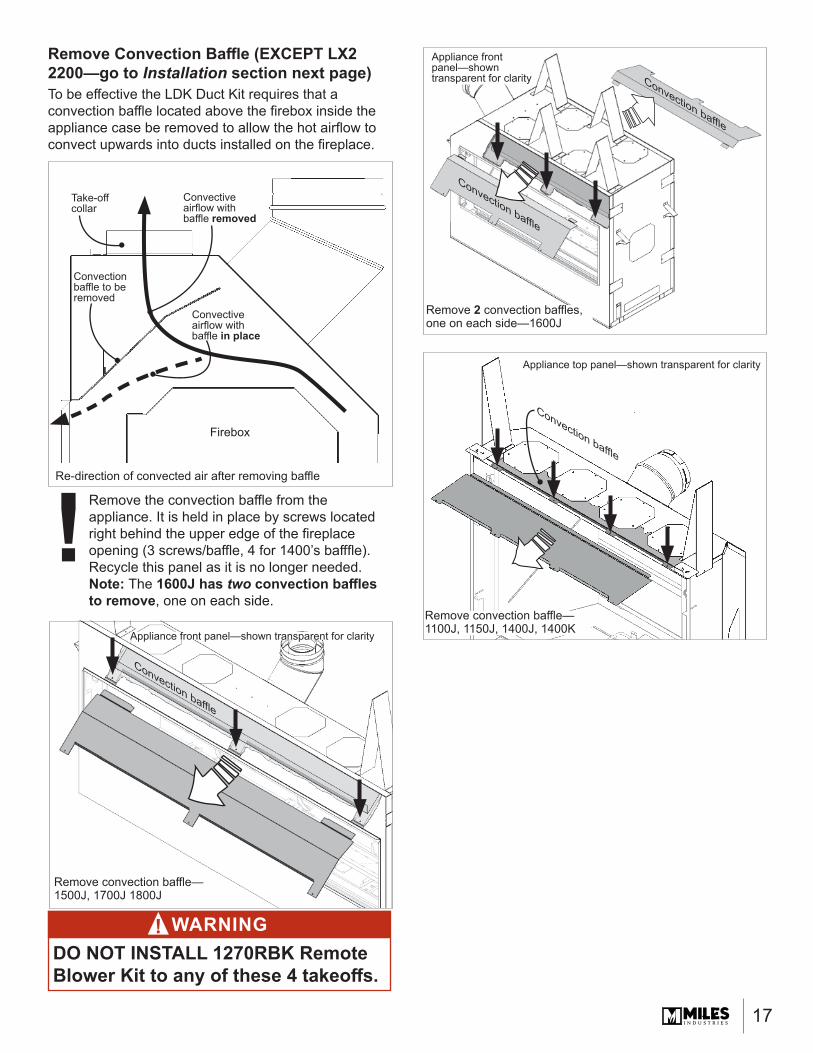
Remove Convection Baffl e (EXCEPT LX2 2200—go to Installation section next page)To be eff ective the LDK Duct Kit requires that a convection baffl e located above the fi rebox inside the appliance case be removed to allow the hot airfl ow to convect upwards into ducts installed on the fi replace.
Remove the convection baffl e from the appliance. It is held in place by screws located right behind the upper edge of the fi replace opening (3 screws/baffl e, 4 for 1400’s baff fl e). Recycle this panel as it is no longer needed.Note: The 1600J has two convection baffl es to remove, one on each side.
Remove convection baffl e—1500J, 1700J 1800J
Appliance front panel—shown transparent for clarity
Convection baffl e
Remove 2 convection baffl es, one on each side—1600J
Appliance front panel—shown transparent for clarity
Convection baffl e
Convection baffl e
Convection baffl e to be removed
Convective airfl ow with baffl e removed
Take-off collar
Firebox
Re-direction of convected air after removing baffl e
Convective airfl ow with baffl e in place
WARNINGDO NOT INSTALL 1270RBK Remote Blower Kit to any of these 4 takeoff s.
!
Appliance top panel—shown transparent for clarity
Remove convection baffl e—1100J, 1150J, 1400J, 1400K
Convection baffl e
!
18
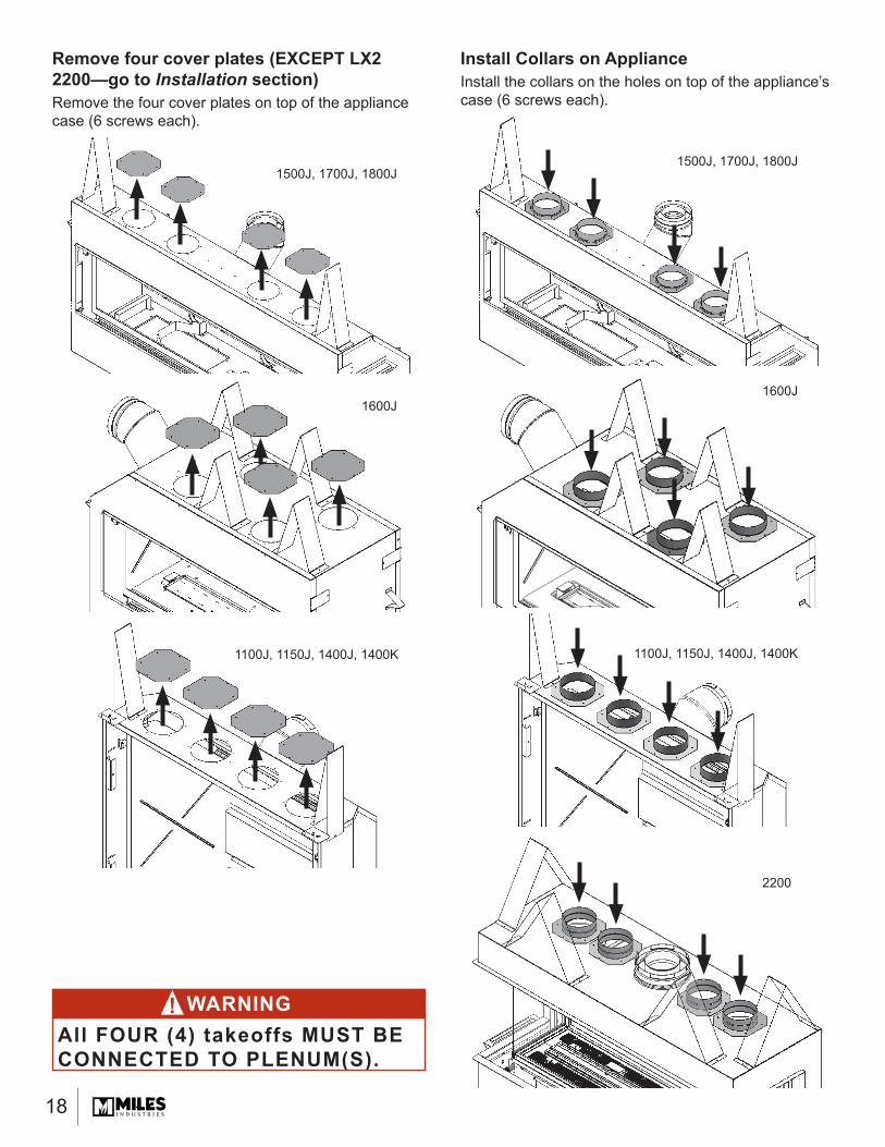
Install Collars on ApplianceInstall the collars on the holes on top of the appliance’s case (6 screws each).
1600J1600J
1100J, 1150J, 1400J, 1400K 1100J, 1150J, 1400J, 1400K
1500J, 1700J, 1800J
Remove four cover plates (EXCEPT LX2 2200—go to Installation section)Remove the four cover plates on top of the appliance case (6 screws each).
WARNINGAll FOUR (4) takeoffs MUST BE CONNECTED TO PLENUM(S).
!
1500J, 1700J, 1800J
2200
19
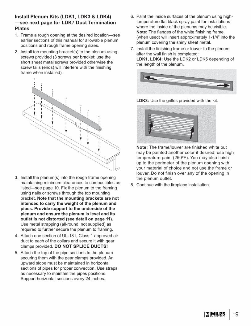
Install Plenum Kits (LDK1, LDK3 & LDK4)—see next page for LDK7 Duct Termination Plates1. Frame a rough opening at the desired location—see
earlier sections of this manual for allowable plenum positions and rough frame opening sizes.
2. Install top mounting bracket(s) to the plenum using screws provided (3 screws per bracket: use the short sheet metal screws provided otherwise the screw tails (ends) will interfere with the fi nishing frame when installed).
3. Install the plenum(s) into the rough frame opening maintaining minimum clearances to combustibles as listed—see page 10. Fix the plenum to the framing using nails or screws through the top mounting bracket. Note that the mounting brackets are not intended to carry the weight of the plenum and pipes. Provide support to the underside of the plenum and ensure the plenum is level and its outlet is not distorted (see detail on page 11). Use metal strapping (all-round, not supplied) as required to further secure the plenum to framing.
4. Attach one section of UL-181, Class 1 approved air duct to each of the collars and secure it with gear clamps provided. DO NOT SPLICE DUCTS!
5. Attach the top of the pipe sections to the plenum securing them with the gear clamps provided. An upward slope must be maintained in horizontal sections of pipes for proper convection. Use straps as necessary to maintain the pipes positions. Support horizontal sections every 24 inches.
6. Paint the inside surfaces of the plenum using high-temperature fl at black spray paint for installations where the inside of the plenums may be visible.Note: The fl anges of the white fi nishing frame (when used) will insert approximately 1-1/4” into the plenum covering the shiny sheet metal.
7. Install the fi nishing frame or louver to the plenum after the wall fi nish is completed:LDK1, LDK4: Use the LDK2 or LDK5 depending of the length of the plenum.
LDK3: Use the grilles provided with the kit.
Note: The frame/louver are fi nished white but may be painted another color if desired; use high temperature paint (250ºF). You may also fi nish up to the perimeter of the plenum opening with your material of choice and not use the frame or louver. Do not fi nish over any of the opening in the plenum outlet.
8. Continue with the fi replace installation.

20
Description Part no.LDK1 48” Quad Hot Air Plenum Kit
48” x 2” quad plenum 40054765” take-off collars (4) 4005478Top mounting bracket/standoff s 4007211#8 slotted drive screws 1/4” (7) 798601
LDK2 48” Outlet Frame Kit for LDK1Aux Frame-SPL 48” x 2” white 4005612
LDK3 14” Double Hot Air Plenums Kit14” x 6” double plenums (2) 40054645” take-off collars (4) 4005478DABL-00-C-SPL 14” x 6” Grilles white (2) 4005614
Top mounting bracket/standoff s (2) 4005566#8 slotted drive screws 1/4” (6) 798601
LDK4 38” Quad Hot Air Plenum Kit38” x 2” quad plenum 40054775” take-off collars (4) 4005478Top mounting bracket/standoff s 4007213#8 slotted drive screws 1/4” (7) 798601
LDK5 38” Outlet Frame Kit for LDK4Aux Frame-SPL 38” x 2” white 4005613
LDK6 5” Aluminum 2-ply Flex Kit5” dia 10’ (uncompressed) aluminum chimney liners (2) 4005635
4.5” - 6.5” ss gear clamps (8) 4005642LDK7 Duct Termination Plates
Plate and collar assembly (2) 40067475” take-off collars (4) 4005478Screws 8 x 3/8 tap PN HD PH (12) 100A757
Repair Parts List
Each LDK kit is sold separately.
Install Duct Termination Plates (LKD7)—see previous page for LDK1, LDK3 & LDK4 Plenum kits1. Frame a rough opening and platform at the desired
location—see earlier sections of this manual for allowable duct termination plates positions and rough frame opening sizes.
2. On each duct termination plate, rotate both stand-off s to the vertical position and secure in place using screws provided.
3. Install the termination plates into the framing ensuring collars/pipes on underside of plates maintain 1 inch clearance to combustibles and clearance to combustible above the plates are maintained as listed on page 13.The termination plates perimeter may be trimmed as necessary to accommodate framing. Secure the termination plate to framing using screws or nails to avoid movement.
4. Attach one section of UL-181, Class 1 approved air duct to each of the collars and secure it with gear clamps provided. DO NOT SPLICE DUCTS!
5. Attach the top of the pipe sections to the duct termination plates securing them with the gear clamps provided. An upward slope must be maintained in horizontal sections of pipes for proper convection. Use straps as necessary to maintain the pipes positions. Support horizontal sections every 24 inches.
6. Continue with the fi replace installation.
2 stand-off s per plate
21
Designed and Manufactured by / for Miles Industries Ltd. 190 – 2255 Dollarton Highway, North Vancouver, BC, CANADA V7H 3B1
Tel. 604-984-3496 Fax 604-984-0246 www.valorfi replaces.com
Because our policy is one of constant development and improvement, details may vary slightly from those given in this publication.
LDK4
LDK3
LDK5
LDK6
LDK2
LDK7
LDK1

22
!
© 2018 Tous droits réservés, Miles Industries Ltd.
ApplicationCe système de canalisation d’air redistribue l’air chaud émanant du foyer à l’endroit désiré en utilisant la convec-tion naturelle sans nécessiter de ventilateur. LDK1, LDK3 et LDK4 : la sortie d’air chaud est dirigée plus haut sur le mur, sur les murs de côté ou même dans une pièce adjacente. LKD7 : la sortie d’air chaud est dirigée à travers un espace (min. 2-1/2”) entre le mur au-dessus du foyer et le plafond. Avec le LDK7, la sortie d’air doit être dans la même pièce que le foyer.Ce qui résulte en un mur aux températures moins chaudes au-dessus du foyer et permet d’y placer des oeuvres d’art, télévision, et ainsi de suite.Il est déconseillé d’installer les Ventilateurs de circulation d’air 1195CFK et 1595CFK avec le Système HeatShift.Les kits LDK1, LDK3, LDK4 ou LDK7 peuvent être utilisés avec les modèles de foyers listés ci-haut.De plus, l’air chaud peut être extrait du système de canali-sation en raccordant le Ventilateur de zone 1270RBK au plénum (LDK1 et LDK4 SEULEMENT).Ce kit est compatible avec les foyers listés ci-dessus seulement. Les foyers plus anciens ne sont pas compati-bles avec ce kit.Note : Ces directives doivent être utilisées conjointement avec les directives d’installation fournies avec le foyer.
Note : À l’exception des modèles 2200, un défl ecteur de convection dans le foyer doit être enlevé pour que ce système fonctionne bien—lisez attentivement les directives.
Pour certains modèles, l’utilisation de ce système permet des dégagements au manteau ou tablette plus bas—voir pages 36–37. Ces dégagements ne sont permis qu’avec l’utilisation du système LDK et lorsque le défl ecteur de convection a été enlevé.
HomologationsLes kits LDK1, LDK3, LDK4, LDK7 sont homologués par l’ASN (CSA) pour usage avec les foyers Valor indiqués ci-dessus—NE PAS les utiliser avec d’autres modèles.Le système HeatShift peut aussi être utilisé pour réduire la température de la surface du mur sur les installations extérieures.Un conduit de 5 pouces de diamètre (non inclus) utilisé avec ces kits doit être fabriqué de métal et doit répon-dre aux normes UL-181 Class 1 Air Duct. Les conduits souples d’aluminium sont acceptables s’ils répondent aux normes UL-181 Class 1.Quatre kits sont off erts, au choix :• LDK1—Plénum quadruple de 48”• LDK3—Plénums doubles de 14” (2), grilles incluses• LDK4—Plénum quadruple de 38”• LDK7—Plaques d’extrémité des conduits (2)—pour
sortie en cantonnière SEULEMENTAccessoires facultatifs• LDK2—Cadre de fi nition 48”, pour le LDK1• LDK5—Cadre de fi nition 38”, pour le LDK4• LDK6—Conduits souples en aluminium de 5 po de
diamètre à 2 plis—2 longueurs de 10 pi pouvant être coupées à la longueur désirée
AVERTISSEMENTNE PAS couvrir ou placer d’objets devant ou par-dessus une sortie d’air. ÉVITEZ de placer la sortie d’air à moins de 7 pieds (2,13 m) au-dessus du plancher car les tem-pératures de l’air à la sortie sont chaudes!
AVERTISSEMENTNotez qu’avec les sorties d’air chaud près des plafonds de couleurs pâles, ceux-ci peuvent être tachés par la poussière qui se trouverait dans le courant d’air chaud; le(s) plénum(s) placé(s) plus bas sur le mur aideront à diminuer la possibilité de taches.
!
!
Systèmes de canalisation d’air LDK HeatShiftHomologué pour utilisation avec les foyers Valor suivants SEULEMENT : - Optionnel avec 1100J, 1150J, 1400J, 1400K, 1500J, 1600J, 1700J et 1800J- EXIGÉ avec tous les modèles LX2 2200
pour les kits LDK1, LDK2, LDK3, LDK4, LDK5, LDK6 et LDK7
Note : Ce kit doit être installé par un installateur qualifi é, une agence de service ou un fournisseur de gaz au moment de l’installation du foyer. Ces directives doivent être utilisées conjointement avec directives d’installation fournies avec le foyer.INSTALLATEUR : Laissez cette notice avec l’appareil.CONSOMMATEUR : Conservez cette notice pour consultation ultérieure.
DIRECTIVES D’INSTALLATION
LE PREMIER FOYER À GAZ RADIANT
MC
® HeatShift
23
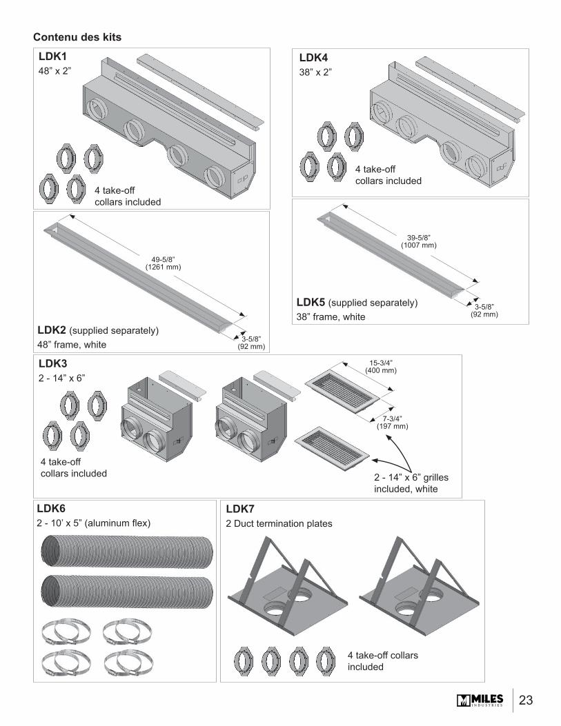
Contenu des kits
3-5/8”(92 mm)
3-5/8”(92 mm)
7-3/4”(197 mm)
LDK438” x 2”
LDK32 - 14” x 6”
LDK62 - 10’ x 5” (aluminum fl ex)
LDK5 (supplied separately)38” frame, white
2 - 14” x 6” grilles included, white
4 take-off collars included
4 take-off collars included
4 take-off collars included
LDK2 (supplied separately)48” frame, white
39-5/8” (1007 mm)
15-3/4” (400 mm)
49-5/8” (1261 mm)
LDK72 Duct termination plates
4 take-off collars included
LDK148” x 2”
24
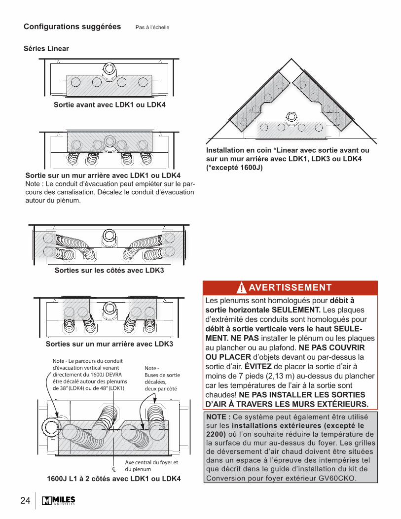
Confi gurations suggérées
AVERTISSEMENTLes plenums sont homologués pour débit à sortie horizontale SEULEMENT. Les plaques d’extrémité des conduits sont homologués pour débit à sortie verticale vers le haut SEULE-MENT. NE PAS installer le plénum ou les plaques au plancher ou au plafond. NE PAS COUVRIR OU PLACER d’objets devant ou par-dessus la sortie d’air. ÉVITEZ de placer la sortie d’air à moins de 7 pieds (2,13 m) au-dessus du plancher car les températures de l’air à la sortie sont chaudes! NE PAS INSTALLER LES SORTIES D’AIR À TRAVERS LES MURS EXTÉRIEURS.
!
Pas à l’échelle
Sortie avant avec LDK1 ou LDK4ti t LDK1 LDK
Installation en coin *Linear avec sortie avant ou sur un mur arrière avec LDK1, LDK3 ou LDK4 (*excepté 1600J)
1600J L1 à 2 côtés avec LDK1 ou LDK4CL
Note - Le parcours du conduit d’évacuation vertical venant directement du 1600J DEVRA être décalé autour des plenums de 38” (LDK4) ou de 48” (LDK1)
Note - Buses de sortie décalées, deux par côté
Axe central du foyer et du plenum
NOTE : Ce système peut également être utilisé sur les installations extérieures (excepté le 2200) où l’on souhaite réduire la température de la surface du mur au-dessus du foyer. Les grilles de déversement d’air chaud doivent être situées dans un espace à l’épreuve des intempéries tel que décrit dans le guide d’installation du kit de Conversion pour foyer extérieur GV60CKO.
Sortie sur un mur arrière avec LDK1 ou LDK4Note : Le conduit d’évacuation peut empiéter sur le par-cours des canalisation. Décalez le conduit d’évacuation autour du plénum.
Sorties sur les côtés avec LDK3
Sorties sur un mur arrière avec LDK3
Séries Linear
25
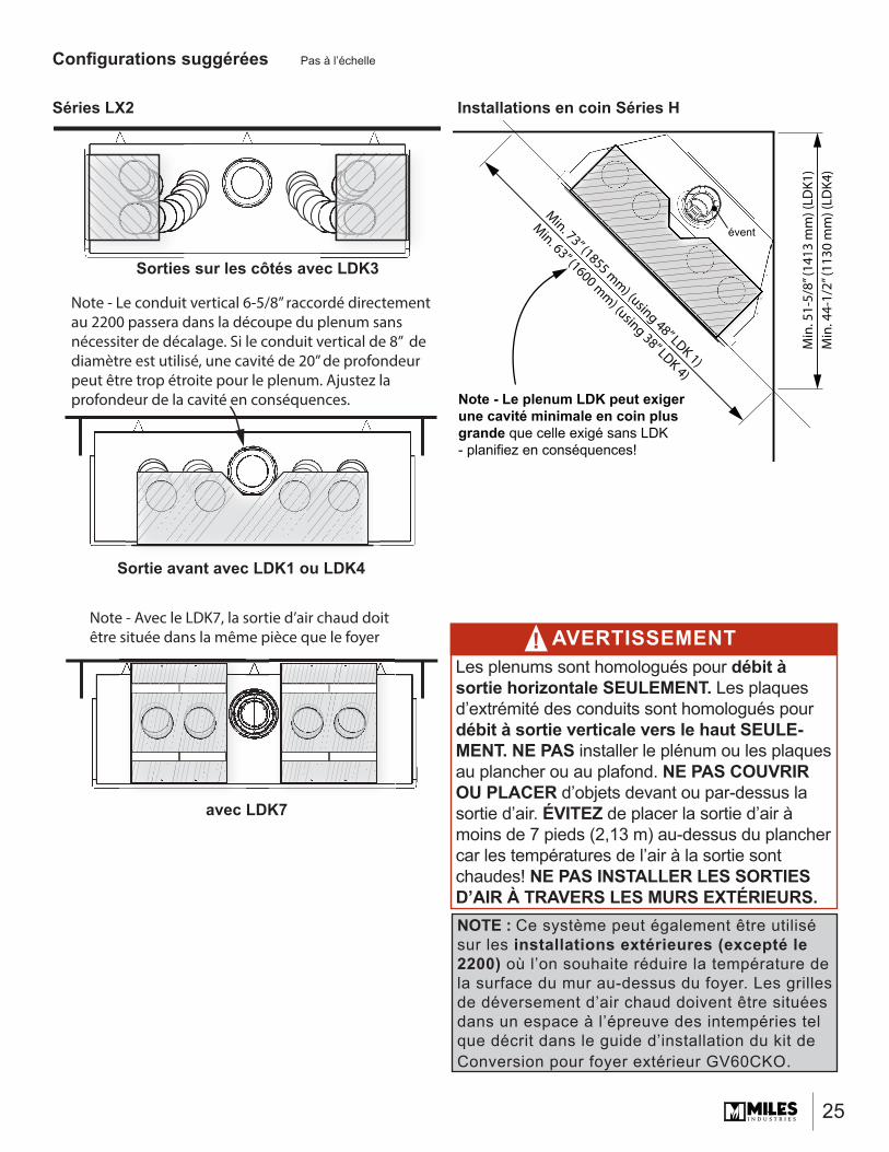
Installations en coin Séries H
Min. 73” (1855 mm) (using 48” LDK 1)
Min. 63” (1600 mm) (using 38” LDK 4)
Min
. 51-
5/8”
(141
3 m
m) (
LDK1
)M
in. 4
4-1/
2” (1
130
mm
) (LD
K4)
Note - Le plenum LDK peut exigerune cavité minimale en coin plus grande que celle exigé sans LDK - planifiez en conséquences!
évent
Confi gurations suggérées Pas à l’échelle
Sortie avant avec LDK1 ou LDK4
Note - Le conduit vertical 6-5/8” raccordé directementau 2200 passera dans la découpe du plenum sans nécessiter de décalage. Si le conduit vertical de 8” de diamètre est utilisé, une cavité de 20” de profondeur peut être trop étroite pour le plenum. Ajustez la profondeur de la cavité en conséquences.
Sorties sur les côtés avec LDK3
Séries LX2
NOTE : Ce système peut également être utilisé sur les installations extérieures (excepté le 2200) où l’on souhaite réduire la température de la surface du mur au-dessus du foyer. Les grilles de déversement d’air chaud doivent être situées dans un espace à l’épreuve des intempéries tel que décrit dans le guide d’installation du kit de Conversion pour foyer extérieur GV60CKO.
avec LDK7
AVERTISSEMENTLes plenums sont homologués pour débit à sortie horizontale SEULEMENT. Les plaques d’extrémité des conduits sont homologués pour débit à sortie verticale vers le haut SEULE-MENT. NE PAS installer le plénum ou les plaques au plancher ou au plafond. NE PAS COUVRIR OU PLACER d’objets devant ou par-dessus la sortie d’air. ÉVITEZ de placer la sortie d’air à moins de 7 pieds (2,13 m) au-dessus du plancher car les températures de l’air à la sortie sont chaudes! NE PAS INSTALLER LES SORTIES D’AIR À TRAVERS LES MURS EXTÉRIEURS.
!Note - Avec le LDK7, la sortie d’air chaud doitêtre située dans la même pièce que le foyer
26
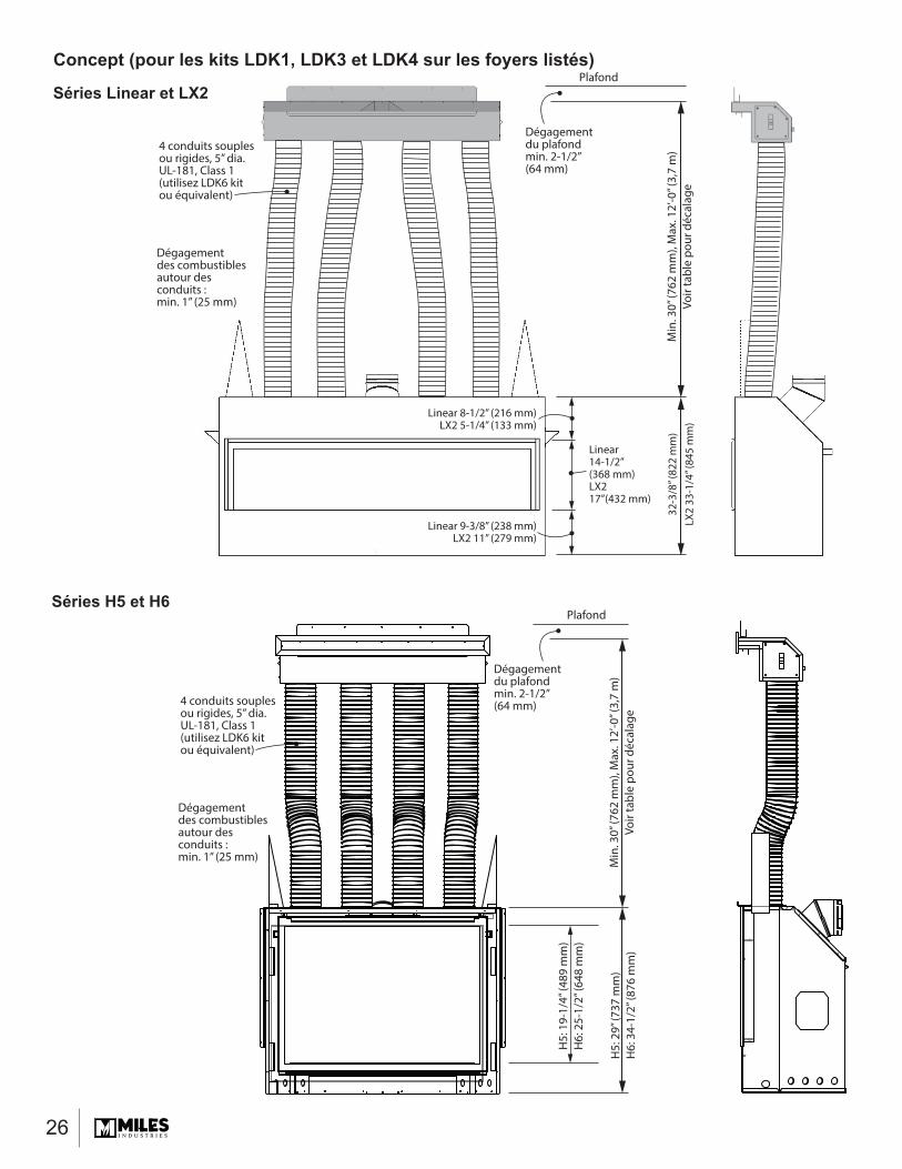
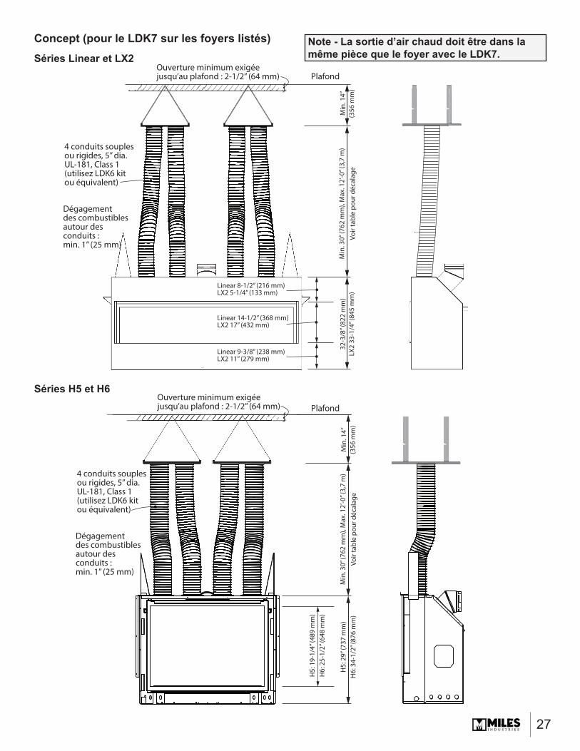
Concept (pour les kits LDK1, LDK3 et LDK4 sur les foyers listés)
4 conduits souplesou rigides, 5” dia.UL-181, Class 1(utilisez LDK6 kitou équivalent)
Dégagementdu plafondmin. 2-1/2”(64 mm)
Dégagementdu plafondmin. 2-1/2”(64 mm)
Min
. 30”
(762
mm
), M
ax. 1
2’-0
” (3,
7 m
)Vo
ir ta
ble
pour
déc
alag
e
Min
. 30”
(762
mm
), M
ax. 1
2’-0
” (3,
7 m
)Vo
ir ta
ble
pour
déc
alag
e
32-3
/8” (
822
mm
)LX
2 33
-1/4
” (84
5 m
m)
Plafond
Dégagementdes combustiblesautour desconduits : min. 1” (25 mm)
4 conduits souplesou rigides, 5” dia.UL-181, Class 1(utilisez LDK6 kitou équivalent)
Dégagementdes combustiblesautour desconduits : min. 1” (25 mm)
H5:
29”
(737
mm
)H
6: 3
4-1/
2” (8
76 m
m)
H5:
19-
1/4”
(489
mm
)H
6: 2
5-1/
2” (6
48 m
m)
Plafond
Linear 8-1/2” (216 mm)LX2 5-1/4” (133 mm)
Linear14-1/2”(368 mm)LX217”(432 mm)
Linear 9-3/8” (238 mm)LX2 11” (279 mm)
Séries Linear et LX2
Séries H5 et H6
27
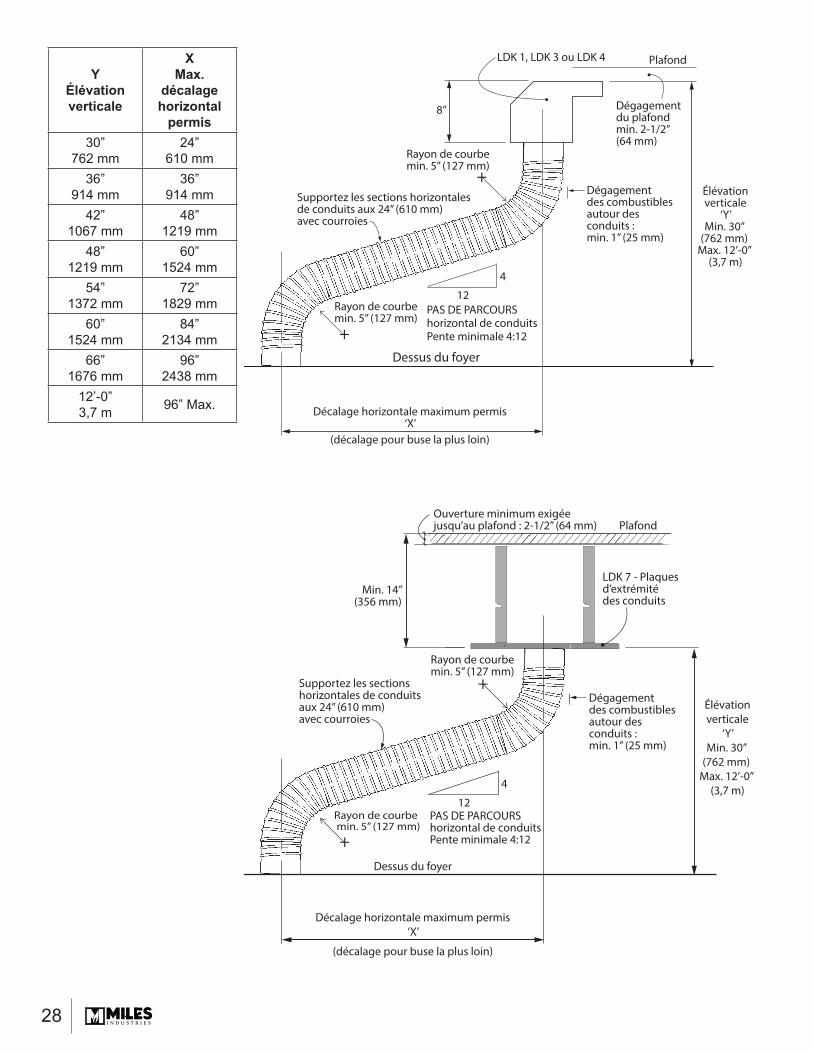
Concept (pour le LDK7 sur les foyers listés)
4 conduits souplesou rigides, 5” dia.UL-181, Class 1(utilisez LDK6 kitou équivalent)
Ouverture minimum exigée jusqu’au plafond : 2-1/2” (64 mm)
Ouverture minimum exigée jusqu’au plafond : 2-1/2” (64 mm)
Min
. 30”
(762
mm
), M
ax. 1
2’-0
” (3,
7 m
)Vo
ir ta
ble
pour
déc
alag
eM
in. 3
0” (7
62 m
m),
Max
. 12’
-0” (
3,7
m)
Voir
tabl
e po
ur d
écal
age
32-3
/8” (
822
mm
)LX
2 33
-1/4
” (84
5 m
m)
Plafond
Dégagementdes combustiblesautour desconduits : min. 1” (25 mm)
4 conduits souplesou rigides, 5” dia.UL-181, Class 1(utilisez LDK6 kitou équivalent)
Dégagementdes combustiblesautour desconduits : min. 1” (25 mm)
H5:
29”
(737
mm
)H
6: 3
4-1/
2” (8
76 m
m)
H5:
19-
1/4”
(489
mm
)H
6: 2
5-1/
2” (6
48 m
m)
Plafond
Linear 8-1/2” (216 mm)LX2 5-1/4” (133 mm)
Linear 14-1/2” (368 mm)LX2 17” (432 mm)
Linear 9-3/8” (238 mm)LX2 11” (279 mm)
Min
. 14”
(356
mm
)M
in. 1
4”(3
56 m
m)
Séries Linear et LX2
Séries H5 et H6
Note - La sortie d’air chaud doit être dans la même pièce que le foyer avec le LDK7.
28
YÉlévation verticale
XMax.
décalage horizontal
permis30”
762 mm24”
610 mm36”
914 mm36”
914 mm42”
1067 mm48”
1219 mm48”
1219 mm60”
1524 mm54”
1372 mm72”
1829 mm60”
1524 mm84”
2134 mm66”
1676 mm96”
2438 mm12’-0”3,7 m 96” Max.
Dégagementdu plafondmin. 2-1/2”(64 mm)
Dégagementdes combustiblesautour desconduits : min. 1” (25 mm)
Supportez les sections horizontales de conduits aux 24” (610 mm) avec courroies
PAS DE PARCOURShorizontal de conduitsPente minimale 4:12
Rayon de courbe min. 5” (127 mm)
Rayon de courbe min. 5” (127 mm)
8”
4
12
Élévationverticale
‘Y’Min. 30”
(762 mm) Max. 12’-0”
(3,7 m)
Décalage horizontale maximum permis‘X’
(décalage pour buse la plus loin)
PlafondLDK 1, LDK 3 ou LDK 4
+
+
Dessus du foyer
Dégagementdes combustiblesautour desconduits : min. 1” (25 mm)
Supportez les sections horizontales de conduits aux 24” (610 mm) avec courroies
PAS DE PARCOURShorizontal de conduitsPente minimale 4:12
Rayon de courbe min. 5” (127 mm)
Rayon de courbe min. 5” (127 mm)
Élévationverticale
‘Y’Min. 30”
(762 mm) Max. 12’-0”
(3,7 m)
Décalage horizontale maximum permis‘X’
(décalage pour buse la plus loin)
Dessus du foyer
Min. 14”(356 mm)
4
12
LDK 7 - Plaques d’extrémité des conduits
+
+
PlafondOuverture minimum exigée jusqu’au plafond : 2-1/2” (64 mm)
29
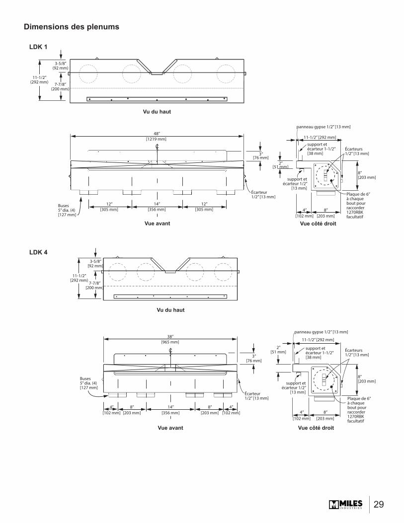
Dimensions des plenums
LDK 4
CL
Vue avant
Vu du haut
Vue côté droit
Buses5” dia. (4)[127 mm]
8”[203 mm]
8”[203 mm]
4”[102 mm]
8”[203 mm]
8”[203 mm]
11-1/2”[292 mm)
7-7/8”[200 mm]
3-5/8”[92 mm]
4”[102 mm]
4”[102 mm]
Écarteurs1/2” [13 mm]
Plaque de 6” à chaque bout pourraccorder1270RBKfacultatif
11-1/2” [292 mm]
panneau gypse 1/2” [13 mm]
support etécarteur 1-1/2”[38 mm]
support etécarteur 1/2”
[13 mm]
2”[51 mm]
3”[76 mm]
Écarteur1/2” [13 mm]
38”[965 mm]
14”[356 mm]
LDK 1
CL
Vu du haut
11-1/2”(292 mm) 7-7/8”
(200 mm)
3-5/8”(92 mm)
Vue avant Vue côté droit
48”[1219 mm]
Buses5” dia. (4)[127 mm]
12”[305 mm]
14”[356 mm]
12”[305 mm]
2”[51 mm]
4”[102 mm]
8”[203 mm]
8”[203 mm]
Écarteurs1/2” [13 mm]
Plaque de 6” à chaque bout pourraccorder1270RBKfacultatif
11-1/2” [292 mm]
panneau gypse 1/2” [13 mm]
support etécarteur 1-1/2”[38 mm]
support etécarteur 1/2”
[13 mm]
3”[76 mm]
Écarteur1/2” [13 mm]
30
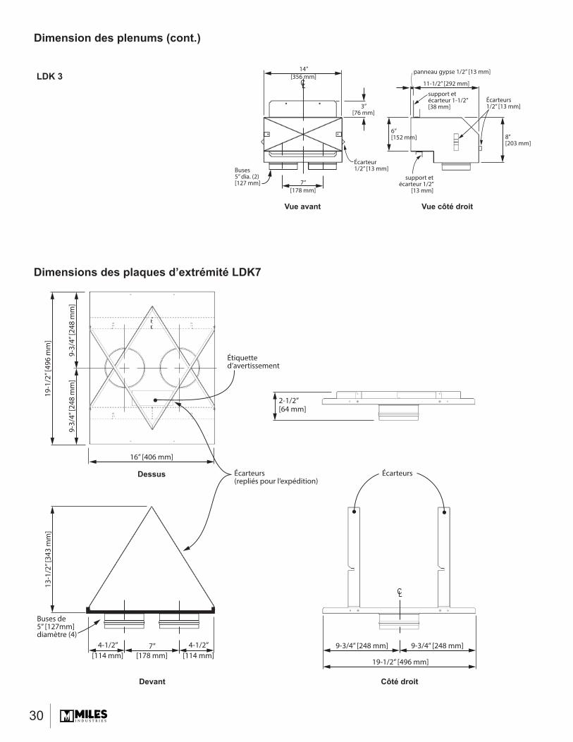
Dimension des plenums (cont.)
Dimensions des plaques d’extrémité LDK7
CL
2-1/2”[64 mm]
Étiquetted’avertissement
Écarteurs
Buses de5” [127mm] diamètre (4)
7”[178 mm]
4-1/2”[114 mm]
4-1/2”[114 mm]
9-3/4” [248 mm] 9-3/4” [248 mm]
19-1
/2” [
496
mm
]13
-1/2
” [34
3 m
m]
16” [406 mm]
19-1/2” [496 mm]
9-3/
4” [2
48 m
m]
9-3/
4” [2
48 m
m]
Écarteurs(repliés pour l’expédition)
Devant
Dessus
Côté droit
LDK 3CL
Vue avant Vue côté droit
14”[356 mm]
Buses5” dia. (2)[127 mm] 7”
[178 mm]
8”[203 mm]
6”[152 mm]
Écarteurs1/2” [13 mm]
11-1/2” [292 mm]
panneau gypse 1/2” [13 mm]
support etécarteur 1-1/2”[38 mm] 3”
[76 mm]
support etécarteur 1/2”
[13 mm]
Écarteur1/2” [13 mm]
31
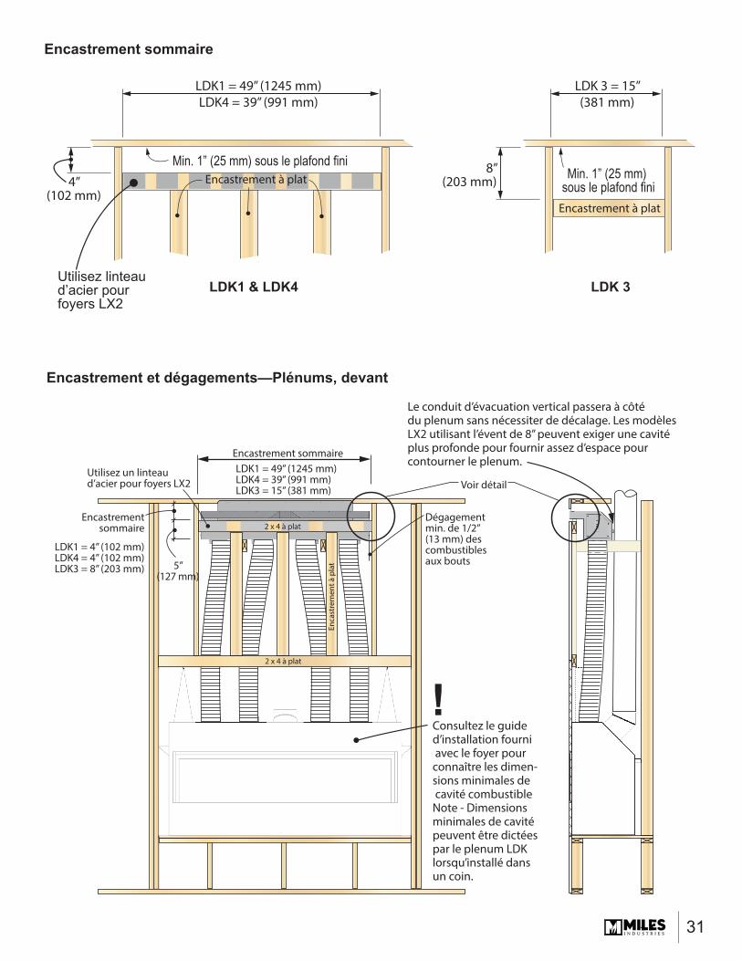
Encastrement sommaire
Utilisez linteaud’acier pourfoyers LX2
LDK1 = 49” (1245 mm)LDK4 = 39” (991 mm)
LDK1 & LDK4 LDK 3
LDK 3 = 15”(381 mm)
4”(102 mm)
Encastrement à plat
Encastrement à plat
Min. 1” (25 mm) sous le plafond finiMin. 1” (25 mm)
sous le plafond fini8”
(203 mm)
Encastrement sommaire
Encastrementsommaire
Consultez le guided’installation fourni avec le foyer pourconnaître les dimen-sions minimales de cavité combustibleNote - Dimensionsminimales de cavité peuvent être dictées par le plenum LDKlorsqu’installé dans un coin.
Dégagementmin. de 1/2” (13 mm) descombustiblesaux bouts
Voir détailLDK1 = 49” (1245 mm)LDK4 = 39” (991 mm)LDK3 = 15” (381 mm)
LDK1 = 4” (102 mm)LDK4 = 4” (102 mm)LDK3 = 8” (203 mm)
2 x 4 à plat
2 x 4 à plat
Enca
stre
men
t à p
lat
Le conduit d’évacuation vertical passera à côté du plenum sans nécessiter de décalage. Les modèles LX2 utilisant l’évent de 8” peuvent exiger une cavité plus profonde pour fournir assez d’espace pour contourner le plenum.
5”(127 mm)
Utilisez un linteaud’acier pour foyers LX2
Encastrement et dégagements—Plénums, devant
!

32
4”(102 mm)
8”(203 mm)
LDK1 & LDK4
LDK3
Encastrementà plat
Encastrementà plat
Dégagement min. de 1-1/2” (38 mm) descombustibles au-dessus
Plafond
Plafond
Dégagement min. de 2-1/2” (64 mm) du plafond
Dégagement min. de 2-1/2” (64 mm) du plafond
1/2”(13 mm)
Dégagementsmin. de 1/2” (13 mm)des combustiblessur les côtés et àl’arrière
Dégagement min. de 1-1/2” (38 mm) descombustibles au-dessus
1/2”(13 mm)
Dégagements min. de 1/2” (13 mm)des combustiblessur les côtés et àl’arrière
Dégagementmin. de 1” (25 mm)des combustiblesautour des conduits
Dégagementmin. de 1” (25 mm)des combustiblesautour des conduits
2 x 4 à plat pour supporter le plenum.Conservez un dégagementde 1” (25 mm) des conduits.
5”(127 mm)
Dégagement min. de 2” (51 mm) des combustibles (utilisez un linteaud’acier pour le LX2)
Dégagement min. de 2” (51 mm) des combustibles (utilisez un linteaud’acier pour le LX2)
Encastrement et dégagements—Plénums, côté

33
Plafond
Min. 2-1/2”(64 mm)
4”(102 mm)
Voir dégagements aux combustibles
à la page suivante Min. 14”(356 mm)
Largeur minimale d’ouverture sur le devant et les côtésH5 et L1 - 1500 = 40” (1,02 m)H6 et L2 - 1700 = 50” (1,27 m)LX2 - 2200 = 50“ (1,27 m)L3 - 1800 = 64” (1,63 m)
Contruction àmur combustible
Mur fini exigé pourformer un plenumau-dessus des plaquesd’extrémité des conduits
LDK 7 - Plaquesd’extrémité des conduits (2) pourinstallation horizontaleSEULEMENT!
Plafond continu exigédans la cavité
Note : Des taches causées par lapoussière dans le débit d’air peuvent apparaître sur les plafonds de couleurs pâles. Maximiser la grandeur del’ouverture contribuera à réduirela possibilité de taches.
Écarteur de plaque
Le parcours d’évacuation verticalpeut passer entre les plaquesd’extrémité des conduits
Hauteur des écarteurs
Consultez le guide d’installationfourni avec le foyer pour savoir
les dimensions minimales dela cavité combustible
Panneau de bétonincombustible
Dégagement min. de 1” (25 mm)autour des conduits
2 x 4 à plat pour supporter les plaques si nécessaire - conservez un dégagement de 1” (25 mm) des conduits.
Sortie d’air en cantonnière utilisant les Plaques d’extrémité des conduits LDK7

34
Dégagements des combustibles utilisant le LDK7
4”(102 mm)
4”(102 mm)
4”(102 mm)
4”(102 mm)
4”(102 mm)
4”(102 mm)
4”(1
02 m
m)
4”(1
02 m
m)
13-1
/2” (
343
mm
)
13-1
/2” (
343
mm
)
19-1
/2” (
496
mm
)
16” (406 mm)
Écarteur
Zone incombustibleau-dessus des plaques
Périmètre des plaques peut être taillé pour convenir à l’installation
Encastrement combustible permis sous les plaques
Conduits de 5” (127 mm) diamètre - conservez 1” (25 mm)
de dégagement jusqu’aux matériaux combustiblesDevant
Dessus
Côté droit
Écarteur
Écarteurs
35
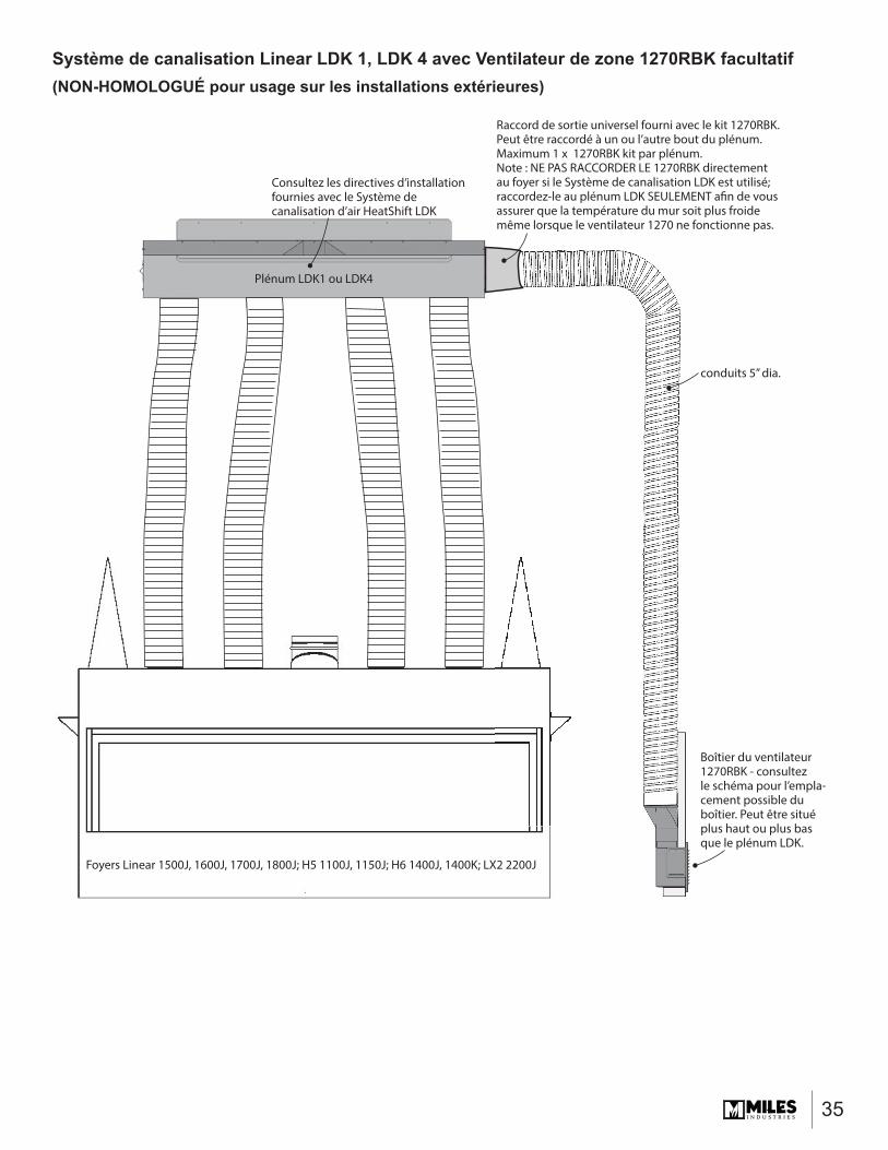
Système de canalisation Linear LDK 1, LDK 4 avec Ventilateur de zone 1270RBK facultatif(NON-HOMOLOGUÉ pour usage sur les installations extérieures)
Plénum LDK1 ou LDK4
Foyers Linear 1500J, 1600J, 1700J, 1800J; H5 1100J, 1150J; H6 1400J, 1400K; LX2 2200J
Consultez les directives d’installation fournies avec le Système decanalisation d’air HeatShift LDK
Raccord de sortie universel fourni avec le kit 1270RBK. Peut être raccordé à un ou l’autre bout du plénum.Maximum 1 x 1270RBK kit par plénum.Note : NE PAS RACCORDER LE 1270RBK directementau foyer si le Système de canalisation LDK est utilisé;raccordez-le au plénum LDK SEULEMENT afin de vousassurer que la température du mur soit plus froidemême lorsque le ventilateur 1270 ne fonctionne pas.
Boîtier du ventilateur 1270RBK - consultez le schéma pour l’empla-cement possible du boîtier. Peut être situéplus haut ou plus bas que le plénum LDK.
conduits 5” dia.
36
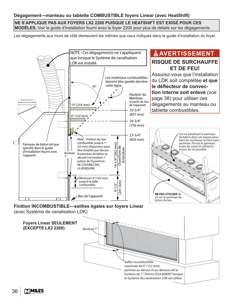
Les dégagements aux murs de côté demeurent les mêmes que ceux indiqués dans le guide d’installation du foyer.
Dégagement—manteau ou tablette COMBUSTIBLE foyers Linear (avec HeatShift)
Finition INCOMBUSTIBLE—saillies égales sur foyers Linear (avec Système de canalisation LDK)
Bas de l’appareil
6” (152 mm)
10” (254 mm)
14-1
/4” (
362
mm
)O
uver
ture
de
la b
ordu
re
9-1/
2”(2
41 m
m)
Note : Finition du mur combustible jusqu’à 1” (25 mm) d’épaisseur peutêtre installée par-dessus le panneau de béton et abouté à la bordure 1“autour de l’ouverture. NE COUVREZ PASLA BORDURE!
Panneau de béton tel quespécifié dans le guided’installation fourni avecl’appareil
Bordure1”
Minimum 4” (102 mm)jusqu’à la dallecombustible
Les matériaux combustiblesdoivent être gardés derrièrecette ligne
23-3/4”(603 mm)
29-3/4”(756 mm)
33-3/4”(857 mm)
45°
NOTE : Ces dégagements ne s’appliquent que lorsque le Système de canalisation LDK est installé.
Hauteur du Manteau(à partir du bas de l’appareil)
Saillie incombustiblemaximale de 6” (152 mm)permise au-dessus et au-dessous de la bordure de 1“. Permis SEULEMENT lorsque le Système de canalisation LDK est utilisé.
Bordure 1”
Les vis pénétrant le panneaude béton dans cet espace pourfixez les manteaux ou finis sontpermises. Percez le panneauavant de visser et utilisez lemoins de vis possible.
NE PAS UTILISER devis sur le panneau de béton du bas
AVERTISSEMENTRISQUE DE SURCHAUFFE
ET DE FEU! Assurez-vous que l’installation du LDK soit complétée et que le défl ecteur de convec-tion interne soit enlevé (voir page 38) pour utiliser ces dégagements au manteau ou tablette combustibles.
!
Foyers Linear SEULEMENT (EXCEPTÉ LX2 2200)
NE S’APPLIQUE PAS AUX FOYERS LX2 2200 PUISQUE LE HEATSHIFT EST EXIGÉ POUR CES MODÈLES. Voir le guide d’installation fourni avec le foyer 2200 pour plus de détails sur les dégagements.
37
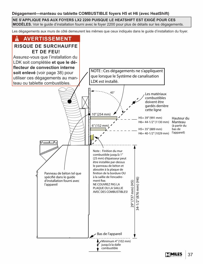
Les dégagements aux murs de côté demeurent les mêmes que ceux indiqués dans le guide d’installation du foyer.
Dégagement—manteau ou tablette COMBUSTIBLE foyers H5 et H6 (avec HeatShift)
AVERTISSEMENTRISQUE DE SURCHAUFFE
ET DE FEU! Assurez-vous que l’installation du LDK soit complétée et que le dé-fl ecteur de convection interne soit enlevé (voir page 38) pour utiliser ces dégagements au man-teau ou tablette combustibles.
!
29” (
737
mm
) (H
5)34
-1/2
” (87
6 m
m) (
H6)
45°
H5= 35” (889 mm)H6= 40-1/2” (1029 mm)
H5= 39” (991 mm)H6= 44-1/2” (1130 mm)
Bas de l’appareil
6” (152 mm)
10” (254 mm)
Note : Finition du mur combustible jusqu’à 1” (25 mm) d’épaisseur peutêtre installée par-dessus le panneau de béton et aboutée à la plaque definition de la bordure OUà la saillie de l’encadre-ment fixe.NE COUVREZ PAS LA PLAQUE OU LA SAILLIEAVEC DES COMBUSTIBLES!
Panneau de béton tel quespécifié dans le guided’installation fourni avecl’appareil
Minimum 4” (102 mm)jusqu’à la dallecombustible
Les matériaux combustiblesdoivent être gardés derrièrecette ligne
NOTE : Ces dégagements ne s’appliquent que lorsque le Système de canalisation LDK est installé.
Hauteur du Manteau(à partir du bas de l’appareil)
NE S’APPLIQUE PAS AUX FOYERS LX2 2200 PUISQUE LE HEATSHIFT EST EXIGÉ POUR CES MODÈLES. Voir le guide d’installation fourni avec le foyer 2200 pour plus de détails sur les dégagements.
38
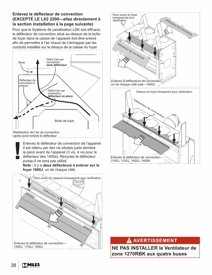
Enlevez le défl ecteur de convection (EXCEPTÉ LE LX2 2200—allez directement à la section Installation à la page suivante)Pour que le Système de canalisation LDK soit effi cace, le défl ecteur de convection situé au-dessus de la boîte de foyer dans la caisse de l’appareil doit être enlevé afi n de permettre à l’air chaud de s’échapper par les conduits installés sur le dessus de la caisse du foyer.
Enlevez le défl ecteur de convection de l’appareil.Il est retenu par des vis situées juste derrière la paroi avant de l’appareil (3 vis, 4 vis pour le défl ecteur des 1400s). Recyclez le défl ecteur puisqu’il ne sera pas utilisé.Note : Il y a deux défl ecteurs à enlever sur le foyer 1600J, un de chaque côté.
AVERTISSEMENTNE PAS INSTALLER le Ventilateur de zone 1270RBK aux quatre buses
!Enlevez le défl ecteur de convection—1500J, 1700J, 1800J
Paroi avant de l’appareil transparente pour clarifi cation
Défl ecteur de convection
Défl ecteur de convection à enlever
Débit d’air par convection, sans défl ecteur
Buse
Boîte de foyer
Redirection de l’air de convection après avoir enlevé le défl ecteur
Débit d’air par convection, défl ecteur en place
!
Enlevez 2 défl ecteurs de convection, un de chaque côté side—1600J
Paroi avant du foyer transparente pour clarifi cation
Défl ecteur de convection
Défl ecteur de convection
Dessus du foyer transparent pour clarifi cation
Enlevez le défl ecteur de convection—1100J, 1150J, 1400J, 1400K
Défl ecteur de convection

39
Installez les buses sur le foyerInstallez les quatre buses HeatShift sur les trous du dessus de la caisse du foyer (6 vis chacune).
1600J
1100J, 1150J, 1400J, 1400K
1600J
1500J, 1700J, 1800J
AVERTISSEMENTLes QUATRE (4) buses DOIVENT ÊTRE RACCORDÉES AU(X) PLENUM(S).
!
Enlevez les quatre couvercles du dessus (EXCEPTÉ le LX2 2200—allez directement à la section Installation)Enlevez les quatre couvercles du dessus de la caisse de l’appareil (6 vis chacune).
2200
1100J, 1150J, 1400J, 1400K
1500J, 1700J, 1800J
40
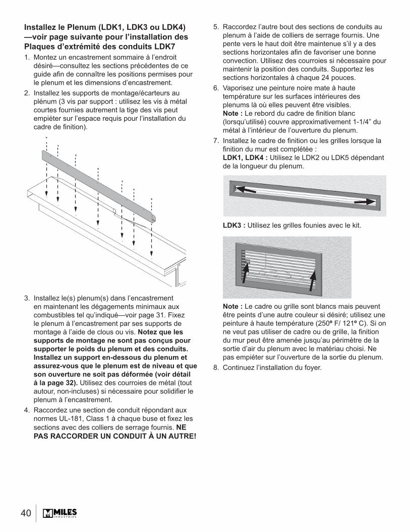
5. Raccordez l’autre bout des sections de conduits au plenum à l’aide de colliers de serrage fournis. Une pente vers le haut doit être maintenue s’il y a des sections horizontales afi n de favoriser une bonne convection. Utilisez des courroies si nécessaire pour maintenir la position des conduits. Supportez les sections horizontales à chaque 24 pouces.
6. Vaporisez une peinture noire mate à haute température sur les surfaces intérieures des plenums là où elles peuvent être visibles. Note : Le rebord du cadre de fi nition blanc (lorsqu’utilisé) couvre approximativement 1-1/4” du métal à l’intérieur de l’ouverture du plenum.
7. Installez le cadre de fi nition ou les grilles lorsque la fi nition du mur est complétée :LDK1, LDK4 : Utilisez le LDK2 ou LDK5 dépendant de la longueur du plenum.
LDK3 : Utilisez les grilles founies avec le kit.
Note : Le cadre ou grille sont blancs mais peuvent être peints d’une autre couleur si désiré; utilisez une peinture à haute température (250º F/ 121º C). Si on ne veut pas utiliser de cadre ou de grille, la fi nition du mur peut être amenée jusqu’au périmètre de la sortie d’air du plenum avec le matériau choisi. Ne pas empiéter sur l’ouverture de la sortie du plenum.
8. Continuez l’installation du foyer.
Installez le Plenum (LDK1, LDK3 ou LDK4)—voir page suivante pour l’installation des Plaques d’extrémité des conduits LDK71. Montez un encastrement sommaire à l’endroit
désiré—consultez les sections précédentes de ce guide afi n de connaître les positions permises pour le plenum et les dimensions d’encastrement.
2. Installez les supports de montage/écarteurs au plénum (3 vis par support : utilisez les vis à métal courtes fournies autrement la tige des vis peut empiéter sur l’espace requis pour l’installation du cadre de fi nition).
3. Installez le(s) plenum(s) dans l’encastrement en maintenant les dégagements minimaux aux combustibles tel qu’indiqué—voir page 31. Fixez le plenum à l’encastrement par ses supports de montage à l’aide de clous ou vis. Notez que les supports de montage ne sont pas conçus pour supporter le poids du plenum et des conduits. Installez un support en-dessous du plenum et assurez-vous que le plenum est de niveau et que son ouverture ne soit pas déformée (voir détail à la page 32). Utilisez des courroies de métal (tout autour, non-incluses) si nécessaire pour solidifi er le plenum à l’encastrement.
4. Raccordez une section de conduit répondant aux normes UL-181, Class 1 à chaque buse et fi xez les sections avec des colliers de serrage fournis. NE PAS RACCORDER UN CONDUIT À UN AUTRE!
41
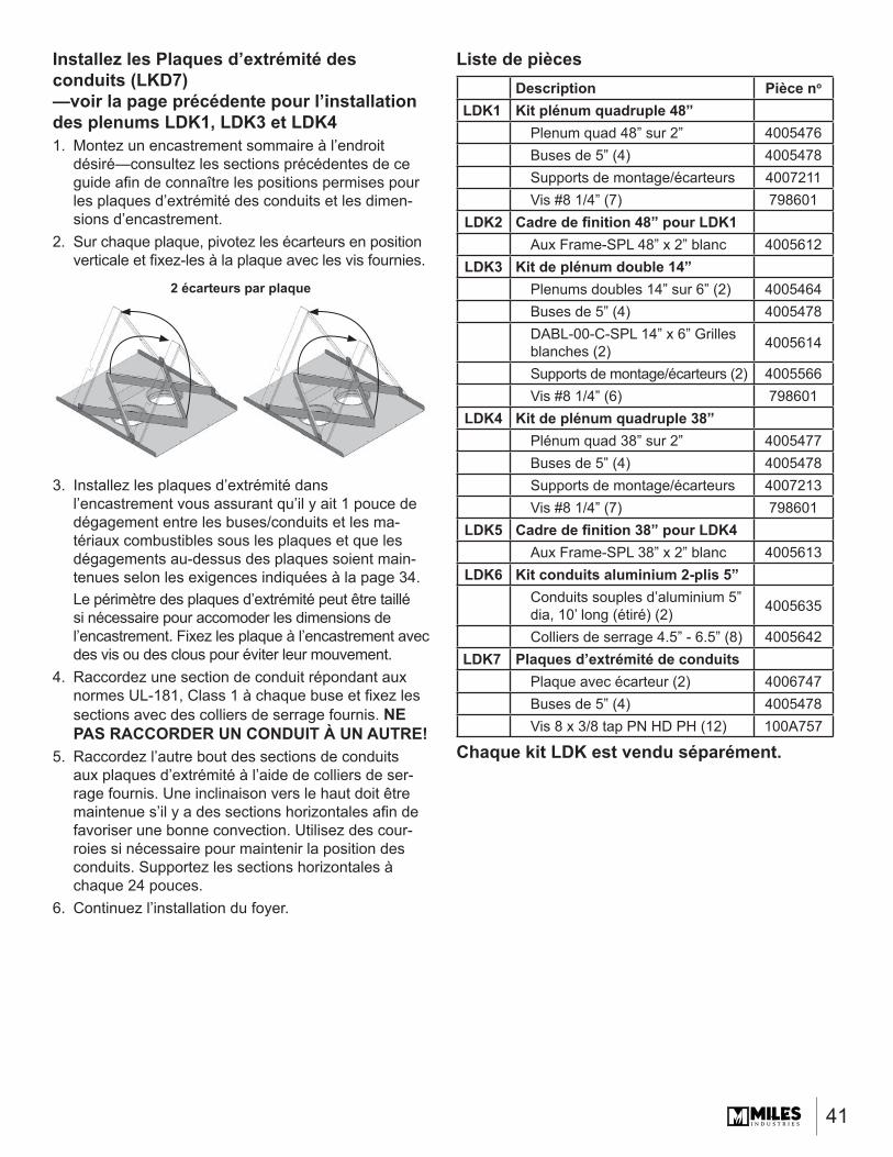
Description Pièce no
LDK1 Kit plénum quadruple 48”Plenum quad 48” sur 2” 4005476Buses de 5” (4) 4005478Supports de montage/écarteurs 4007211Vis #8 1/4” (7) 798601
LDK2 Cadre de fi nition 48” pour LDK1Aux Frame-SPL 48” x 2” blanc 4005612
LDK3 Kit de plénum double 14”Plenums doubles 14” sur 6” (2) 4005464Buses de 5” (4) 4005478DABL-00-C-SPL 14” x 6” Grilles blanches (2) 4005614
Supports de montage/écarteurs (2) 4005566Vis #8 1/4” (6) 798601
LDK4 Kit de plénum quadruple 38”Plénum quad 38” sur 2” 4005477Buses de 5” (4) 4005478Supports de montage/écarteurs 4007213Vis #8 1/4” (7) 798601
LDK5 Cadre de fi nition 38” pour LDK4Aux Frame-SPL 38” x 2” blanc 4005613
LDK6 Kit conduits aluminium 2-plis 5”Conduits souples d’aluminium 5” dia, 10’ long (étiré) (2) 4005635
Colliers de serrage 4.5” - 6.5” (8) 4005642LDK7 Plaques d’extrémité de conduits
Plaque avec écarteur (2) 4006747Buses de 5” (4) 4005478Vis 8 x 3/8 tap PN HD PH (12) 100A757
Liste de pièces
Chaque kit LDK est vendu séparément.
Installez les Plaques d’extrémité des conduits (LKD7)—voir la page précédente pour l’installation des plenums LDK1, LDK3 et LDK41. Montez un encastrement sommaire à l’endroit
désiré—consultez les sections précédentes de ce guide afi n de connaître les positions permises pour les plaques d’extrémité des conduits et les dimen-sions d’encastrement.
2. Sur chaque plaque, pivotez les écarteurs en position verticale et fi xez-les à la plaque avec les vis fournies.
3. Installez les plaques d’extrémité dans l’encastrement vous assurant qu’il y ait 1 pouce de dégagement entre les buses/conduits et les ma-tériaux combustibles sous les plaques et que les dégagements au-dessus des plaques soient main-tenues selon les exigences indiquées à la page 34.Le périmètre des plaques d’extrémité peut être taillé si nécessaire pour accomoder les dimensions de l’encastrement. Fixez les plaque à l’encastrement avec des vis ou des clous pour éviter leur mouvement.
4. Raccordez une section de conduit répondant aux normes UL-181, Class 1 à chaque buse et fi xez les sections avec des colliers de serrage fournis. NE PAS RACCORDER UN CONDUIT À UN AUTRE!
5. Raccordez l’autre bout des sections de conduits aux plaques d’extrémité à l’aide de colliers de ser-rage fournis. Une inclinaison vers le haut doit être maintenue s’il y a des sections horizontales afi n de favoriser une bonne convection. Utilisez des cour-roies si nécessaire pour maintenir la position des conduits. Supportez les sections horizontales à chaque 24 pouces.
6. Continuez l’installation du foyer.
2 écarteurs par plaque
42
Conçu(e) et fabriqué(e) par / pour Miles Industries Ltd. 190 – 2255 Dollarton Highway, North Vancouver, BC, CANADA V7H 3B1
Tél. 604-984-3496 Téléc. 604-984-0246 www.foyervalor.com
Parce que nous favorisons une politique de développement continu, certains détails de la présente publication peuvent varier.
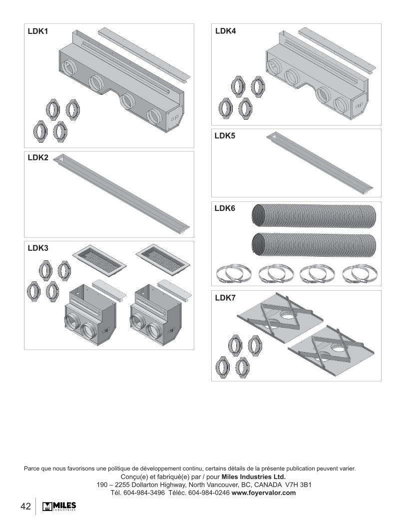
LDK1 LDK4
LDK3
LDK5
LDK6
LDK2
LDK7
Related Documents