Installation Manual for System S700172 John Deere 6068 VR70 General Information..................................................................... 3 Before You Start ....................................................................... 3 Part 1: System Identification and Warnings ............................ 4 Part 2: Air/Oil Separator Tank (AOST) Installation ................... 5 2.1 Preparing for Installation .................................................... 5 2.2 Tank Installation ................................................................. 7 Part 3: Manifold Installation........................................................ 9 3.1 Installing the Bracket and Manifold .................................... 9 Part 4: Cooler Installation ........................................................... 11 Part 5: Installing the Compressor .............................................. 15 5.1 Main Bracket....................................................................... 15 5.2 Installing Air End and Hoses .............................................. 17 4.3 Filling the System with Oil .................................................. 27 Part 6: Control System ................................................................ 29 6.1 Control Box and Wiring ...................................................... 30 6.2 Confirmation Test ............................................................... 31 Part 7: Finishing the Installation ................................................ 32 6.1 Before Starting the Engine Checklist.................................. 32 6.2 After Starting Engine Checklist........................................... 32 Accessory Products from VMAC ............................................... 34 VMAC – Vehicle Mounted Air Compressors Toll Free: 1-888-241-2289 Fax: 1-250-740-3201 1

Welcome message from author
This document is posted to help you gain knowledge. Please leave a comment to let me know what you think about it! Share it to your friends and learn new things together.
Transcript

Installation Manual for System S700172
John Deere 6068 VR70
General Information..................................................................... 3 Before You Start ....................................................................... 3
Part 1: System Identification and Warnings ............................ 4
Part 2: Air/Oil Separator Tank (AOST) Installation ................... 5 2.1 Preparing for Installation .................................................... 5 2.2 Tank Installation ................................................................. 7
Part 3: Manifold Installation ........................................................ 9 3.1 Installing the Bracket and Manifold .................................... 9
Part 4: Cooler Installation ........................................................... 11
Part 5: Installing the Compressor .............................................. 15 5.1 Main Bracket ....................................................................... 15 5.2 Installing Air End and Hoses .............................................. 17 4.3 Filling the System with Oil .................................................. 27
Part 6: Control System ................................................................ 29 6.1 Control Box and Wiring ...................................................... 30 6.2 Confirmation Test ............................................................... 31
Part 7: Finishing the Installation ................................................ 32 6.1 Before Starting the Engine Checklist.................................. 32 6.2 After Starting Engine Checklist ........................................... 32
Accessory Products from VMAC ............................................... 34
VMAC – Vehicle Mounted Air Compressors Toll Free: 1-888-241-2289 Fax: 1-250-740-3201
1
!
!
Document #1930232 Installation Manual for VMAC System S700172 John Deere 6068 VR70
Changes and Revisions Version Revision Details Revised by/date Approved Implemented
A ENGINEERING RELEASE RR 04NOV2014 MP/RD 10 Nov 2014
18 Nov 2014
B ECN 14-079: S700172 FASTENER PACK CHANGES RR 17NOV2014 MP/DB 19 Nov 2014 19 Nov 2014
Important Information The information in this manual is intended for certified VMAC installers who have been trained in installation procedures and for people with mechanical trade certification who have the tools and equipment to properly and safely perform the installation. Do not attempt this installation if you do not have the appropriate mechanical training, knowledge and experience. Follow all safety precautions for underhood mechanical work. Any grinding, bending or restructuring operations for correct fit in modified vehicles must follow standard shop practices.
All hoses, tubes, and wires which are rerouted or shifted during installation must be secure so that they do not contact excessively hot areas or sharp edges. Where possible follow the routing suggestions in this manual.
The VMAC warranty form is located at the back of this manual. This warranty form must be completed and mailed or faxed to VMAC at the time of installation for any subsequent warranty claim to be considered valid.
To order parts, contact your VMAC dealer. Your dealer will ask for the VMAC serial number, part number, description and quantity. To locate your nearest dealer, call 1-888-241-2289.
VMAC recommends covering all hoses and wires for protection.
Copyright 2013
All trademarks used in this manual are the property of the respective copyright holder. The contents of this manual may not be reproduced in any form without the express
written permission of VMAC, 1333 Kipp Road, Nanaimo, BC V9X 1R3. Printed in Canada
VMAC – Vehicle Mounted Air Compressors Toll Free: 1-888-241-2289 Fax: 1-250-740-3201
2

General Information
Before You Start Read this manual before attempting installation so that you can familiarize yourself with the components and how they fit on the vehicle. Identify variations for different engine models and different situations that are listed in the manual. Open the package, unpack the components and identify them.
All fasteners must be torqued to specifications. Use manufacturers torque values for OEM fasteners. Apply Loctite 242 or equivalent on all engine-mounted fasteners. Torque values are with Loctite applied unless otherwise specified. STANDARD GRADE 8 NATIONAL COARSE THREAD Size 1/4 5/16 3/8 7/16 1/2 9/16 5/8 3/4 Foot-pounds (ft-lb) 9 18 35 55 80 110 170 280 Newton meter (N•m) 12 24 47 74 108 149 230 379 STANDARD GRADE 8 NATIONAL FINE THREAD Size 3/8 7/16 1/2 5/8 3/4 Foot-pounds (ft-lb) 40 60 90 180 320 Newton meter (N•m) 54 81 122 244 434 METRIC CLASS 10.9 Size M8 M10 M12 M14 M16 Foot-pounds (ft-lb) 19 41 69 104 174 Newton meter (N•m) 25 55 93 141 236
Hose Information Different frame designations will affect the tank mounting position. If you have to move the tank, the lines may be too short. Measure the hose shortfall and order a Hose Extender Kit. Depending on other installed equipment, it might be necessary to move the air/oil separator tank from its intended location. The hoses used in VMAC compressor systems have a specific inner liner that is compatible with our compressor oil. Use of hoses other than those supplied or recommended by VMAC may cause compressor damage and may void your warranty. Please contact VMAC for replacement hoses and further information.
VMAC – Vehicle Mounted Air Compressors Toll Free: 1-888-241-2289 Fax: 1-250-740-3201
3

Part 1: System Identification and Warnings
□ The System Identification Number Plate must be attached to the equipment at the time of installation. This plate provides information that allows VMAC to assist in customer inquiries and ordering of parts
□ Mark and drill two 7/64-inch holes in a suitable location. This location must be easily visible, such as beside the control box or compressor. Secure the plate with the supplied self-tapping screws
□ Place the S700172 belt routing and safety label beside the control box in a visible location.
□ Complete the warranty form. The VMAC warranty form is located within the system ID package as well as online at: http://vmacair.com/support/warranty/ This warranty form must be completed and mailed or faxed to VMAC at the time of installation for any subsequent warranty claim to be considered valid.
VMAC – Vehicle Mounted Air Compressors Toll Free: 1-888-241-2289 Fax: 1-250-740-3201
4

Part 2: Air/Oil Separator Tank (AOST) Installation
2.1 Preparing for Installation
□ Remove the service panel on the alternator side of the enclosure.
□ Remove the PTO offset housing, bracket, and associated oil fittings (Figure 1) and plug/blank the ports (Figure 2).
Figure 1
REMOVE
VMAC – Vehicle Mounted Air Compressors Toll Free: 1-888-241-2289 Fax: 1-250-740-3201
5

Figure 2
□ Remove the two bolts fastening the bottom of the corner post on the housing to the frame (Figure 3).
Figure 3
INSTALL COVER PLATE AND GASKET
PLUG
REMOVE
VMAC – Vehicle Mounted Air Compressors Toll Free: 1-888-241-2289 Fax: 1-250-740-3201
6
2.2 Tank Installation
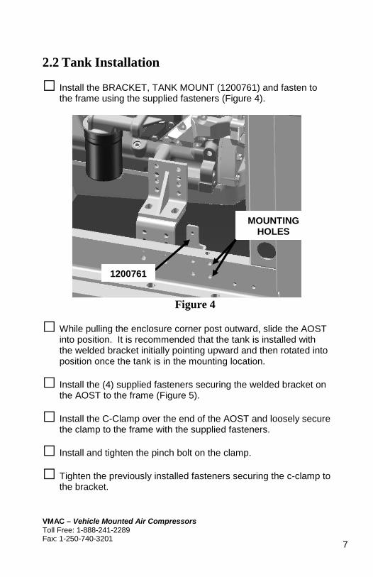
□ Install the BRACKET, TANK MOUNT (1200761) and fasten to the frame using the supplied fasteners (Figure 4).
Figure 4
□ While pulling the enclosure corner post outward, slide the AOST into position. It is recommended that the tank is installed with the welded bracket initially pointing upward and then rotated into position once the tank is in the mounting location.
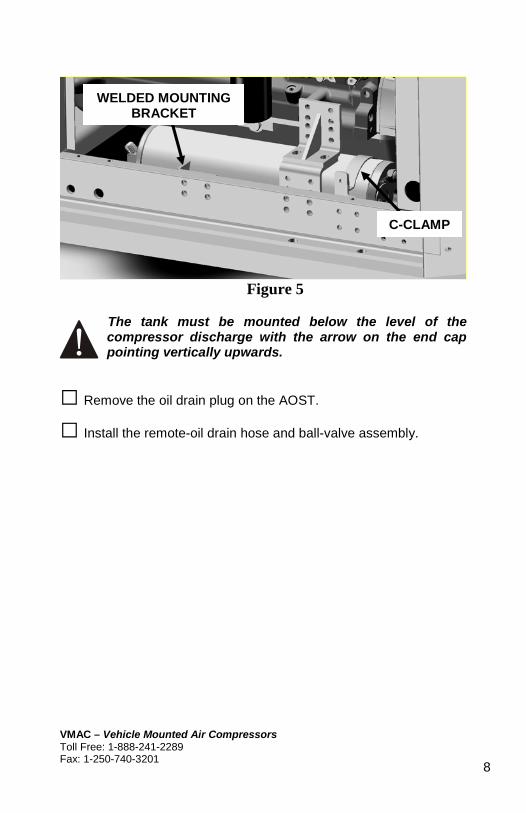
□ Install the (4) supplied fasteners securing the welded bracket on the AOST to the frame (Figure 5).
□ Install the C-Clamp over the end of the AOST and loosely secure the clamp to the frame with the supplied fasteners.
□ Install and tighten the pinch bolt on the clamp.
□ Tighten the previously installed fasteners securing the c-clamp to the bracket.
MOUNTING HOLES
1200761
VMAC – Vehicle Mounted Air Compressors Toll Free: 1-888-241-2289 Fax: 1-250-740-3201
7
!
Figure 5
The tank must be mounted below the level of the compressor discharge with the arrow on the end cap pointing vertically upwards.
□ Remove the oil drain plug on the AOST.
□ Install the remote-oil drain hose and ball-valve assembly.
WELDED MOUNTING BRACKET
C-CLAMP
VMAC – Vehicle Mounted Air Compressors Toll Free: 1-888-241-2289 Fax: 1-250-740-3201
8
Part 3: Manifold Installation
3.1 Installing the Bracket and Manifold
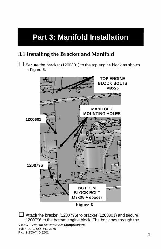
□ Secure the bracket (1200801) to the top engine block as shown in Figure 6.
Figure 6
□ Attach the bracket (1200796) to bracket (1200801) and secure 1200796 to the bottom engine block. The bolt goes through the
MANIFOLD MOUNTING HOLES
TOP ENGINE BLOCK BOLTS
M8x25
1200801
1200796
BOTTOM BLOCK BOLT
M8x35 + spacer
VMAC – Vehicle Mounted Air Compressors Toll Free: 1-888-241-2289 Fax: 1-250-740-3201
9

bracket and the spacer before inserting into the block. See Figure 6.
□ Secure the manifold assembly (4800641) to the bracket (1200801) with the fasteners supplied as shown in Figure 6 and Figure 7.
Figure 7
VMAC – Vehicle Mounted Air Compressors Toll Free: 1-888-241-2289 Fax: 1-250-740-3201
10
Part 4: Cooler Installation
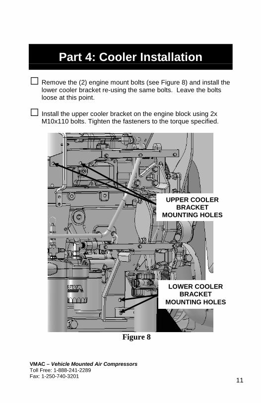
□ Remove the (2) engine mount bolts (see Figure 8) and install the lower cooler bracket re-using the same bolts. Leave the bolts loose at this point.
□ Install the upper cooler bracket on the engine block using 2x M10x110 bolts. Tighten the fasteners to the torque specified.
Figure 8
UPPER COOLER BRACKET
MOUNTING HOLES
LOWER COOLER BRACKET
MOUNTING HOLES
VMAC – Vehicle Mounted Air Compressors Toll Free: 1-888-241-2289 Fax: 1-250-740-3201
11

□ Install the cooler between the two brackets in the orientation shown in Figure 9 using the supplied fasteners in (6) places and tighten to specification.
Figure 9
□ Tighten the fasteners securing the lower bracket to the engine mount.
VMAC – Vehicle Mounted Air Compressors Toll Free: 1-888-241-2289 Fax: 1-250-740-3201
12

!
Figure 10
□ Attach green wire with ring terminal from the cooler fan harness to the ground post of the alternator as indicated in Figure 10.
□ Attach orange wire with ring terminal from the cooler fan harness to the 24v post of the alternator as indicated in Figure 10.
□ Blunt cut orange wire from the fan harness connects to an ignition switched 24v source.
Note: See Figure 11 for cooler-fan wiring schematic.
GROUND POST
24v POST
VMAC – Vehicle Mounted Air Compressors Toll Free: 1-888-241-2289 Fax: 1-250-740-3201
13

Figure 11
VMAC – Vehicle Mounted Air Compressors Toll Free: 1-888-241-2289 Fax: 1-250-740-3201
14

Part 5: Installing the Compressor
5.1 Main Bracket
□ Add a notch to the top left corner of the engine mount to allow for L-bracket clearance. See Figure 12 & Figure 13.
Figure 12
Figure 13
NOTCH
0.65”
1.05”
VMAC – Vehicle Mounted Air Compressors Toll Free: 1-888-241-2289 Fax: 1-250-740-3201
15

!
□ Remove the 3 side engine mounts and attach the L-shaped bracket as shown in Figure 14.
Note: Leave the rear bottom bolt tight to hold engine during installation.
Figure 14
□ Remove the tensioner assembly and idler from the main bracket.
□ Apply Loctite and re-install the tensioner assembly and the idler on the main bracket and torque fasteners to specification.
REMOVE
UPPER FRONT ENGINE MOUNT
LOWER FRONT ENGINE MOUNT
VMAC – Vehicle Mounted Air Compressors Toll Free: 1-888-241-2289 Fax: 1-250-740-3201
16

□ Mount the main bracket to the upper and lower front engine mounts as shown in Figure 14.
□ Apply loctite and install the provided M16 bolts in the two front block mounts. Do not tighten.
□ Snug down the (2X) M16 x 50mm engine mount bolts and torque to specifications.
5.2 Installing Air End and Hoses
□ Install crank pulley. The pulley mounts between the OEM crank pulley and the OEM damper. Use loctite and six M10x25mm bolts provided and torque to specifications.
□ Mount the compressor to the main bracket. Use the two M8x20mm bolts provided to mount the clutch bracket to the front of the main bracket as shown in Figure 15.
Figure 15
M8 BOLTS
VMAC – Vehicle Mounted Air Compressors Toll Free: 1-888-241-2289 Fax: 1-250-740-3201
17

□ Apply loctite and install compressor to main bracket using the three M8 bolts. These bolts are of varying lengths and the positions are shown in Figure 16 . Torque to specifications.
Figure 16
M8X90MM BOLT
M8X100MM BOLT M8X30MM BOLT
VMAC – Vehicle Mounted Air Compressors Toll Free: 1-888-241-2289 Fax: 1-250-740-3201
18

□ Install belt and route as per Figure 17. To remove the tensioner locking pin you can use a 3/8” drive as shown in Figure 17 to relieve tension on the tensioner.
Figure 17
□ Select a suitable location for the heavy-duty air-filter as shown in Figure 18 and Figure 19 in location of customer’s choosing.
□ Install heavy-duty air-filter offset bracket with supplied fasteners and air-filter.
3/8” Drive Locking pin
VMAC – Vehicle Mounted Air Compressors Toll Free: 1-888-241-2289 Fax: 1-250-740-3201
19
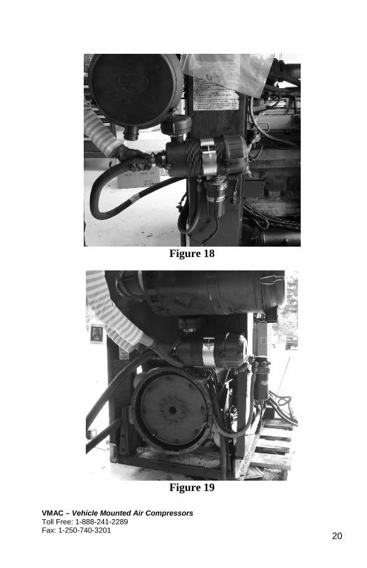
Figure 18
Figure 19
VMAC – Vehicle Mounted Air Compressors Toll Free: 1-888-241-2289 Fax: 1-250-740-3201
20
!
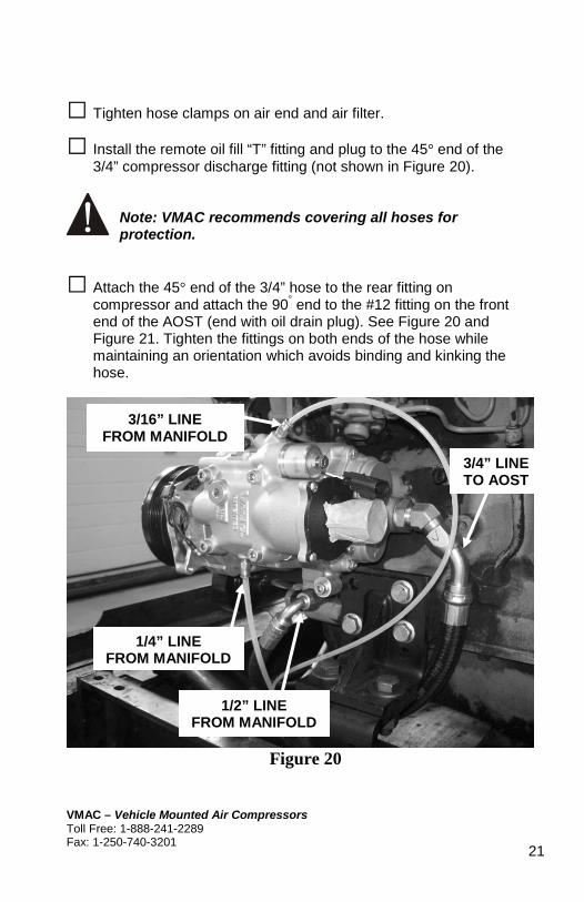
□ Tighten hose clamps on air end and air filter.
□ Install the remote oil fill “T” fitting and plug to the 45° end of the 3/4” compressor discharge fitting (not shown in Figure 20).
Note: VMAC recommends covering all hoses for protection.
□ Attach the 45° end of the 3/4” hose to the rear fitting on compressor and attach the 90° end to the #12 fitting on the front end of the AOST (end with oil drain plug). See Figure 20 and Figure 21. Tighten the fittings on both ends of the hose while maintaining an orientation which avoids binding and kinking the hose.
Figure 20
1/4” LINE FROM MANIFOLD
3/16” LINE FROM MANIFOLD
3/4” LINE TO AOST
1/2” LINE FROM MANIFOLD
VMAC – Vehicle Mounted Air Compressors Toll Free: 1-888-241-2289 Fax: 1-250-740-3201
21

Figure 21
□ Attach the 90°end of the appropriate 1/2” hose to the #8 fitting on the front end of the AOST (end with oil drain plug), see Figure 21. Route the hose over the lower cooler bracket and attached the 45° end to the lower cooler fitting (Figure 22). Tighten the fittings on both ends of the hose while maintaining an orientation which avoids binding and kinking the hose.
□ Attach the 45° end of the appropriate 1/2” hose to the upper fitting on the cooler (Figure 22). Attach the straight end to the fitting on the back side of the manifold (Figure 23). Tighten the fittings on both ends of the hose while maintaining an orientation which avoids binding and kinking the hose.
1/2” LINE TO COOLER
3/4” LINE FROM COMPRESSOR
VMAC – Vehicle Mounted Air Compressors Toll Free: 1-888-241-2289 Fax: 1-250-740-3201
22

Figure 22
1/2” LINE TO MANIFOLD
1/2” LINE FROM AOST
VMAC – Vehicle Mounted Air Compressors Toll Free: 1-888-241-2289 Fax: 1-250-740-3201
23

Figure 23
□ Attach the straight end of the long 1/2” hose to the fitting with the in-line check valve out of the top of the manifold (Figure 23). Route the hose over the lower cooler bracket and follow the other hose route to the compressor. Attach the 90° end to the #8 fitting on the compressor (Figure 20). Tighten the fittings on both ends of the hose while maintaining an orientation which avoids binding and kinking the hose.
□ Attach the 45° end of the short 3/4” hose to the outlet of the AOST (end with the oil level sight tube), see Figure 24. Attach the straight end to the appropriate fitting on the manifold (Figure 25). Tighten the fittings on both ends of the hose while maintaining an orientation which avoids binding and kinking the hose.
1/2” LINE FROM COOLER
1/2” LINE TO COMPRESSOR
3/16” LINE TO COMPRESSOR
1/4” LINE TO COMPRESSOR
VMAC – Vehicle Mounted Air Compressors Toll Free: 1-888-241-2289 Fax: 1-250-740-3201
24

Figure 24
□ Connect the desired fitting/hose combination to the 3/4” female NPT outlet of the manifold to the point of use (Figure 25).
OIL LEVEL SIGHT TUBE
3/4” LINE TO MANIFOLD
VMAC – Vehicle Mounted Air Compressors Toll Free: 1-888-241-2289 Fax: 1-250-740-3201
25
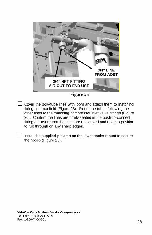
Figure 25
□ Cover the poly-tube lines with loom and attach them to matching fittings on manifold (Figure 23). Route the tubes following the other lines to the matching compressor inlet valve fittings (Figure 20). Confirm the lines are firmly seated in the push-to-connect fittings. Ensure that the lines are not kinked and not in a position to rub through on any sharp edges.
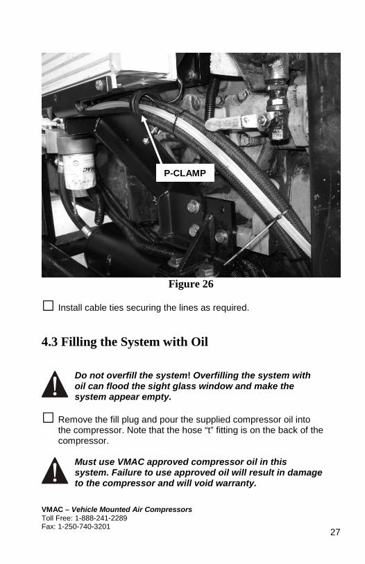
□ Install the supplied p-clamp on the lower cooler mount to secure the hoses (Figure 26).
3/4” NPT FITTING AIR OUT TO END USE
3/4” LINE FROM AOST
VMAC – Vehicle Mounted Air Compressors Toll Free: 1-888-241-2289 Fax: 1-250-740-3201
26
!
!
Figure 26
□ Install cable ties securing the lines as required.
4.3 Filling the System with Oil
Do not overfill the system! Overfilling the system with oil can flood the sight glass window and make the system appear empty.
□ Remove the fill plug and pour the supplied compressor oil into the compressor. Note that the hose “t” fitting is on the back of the compressor.
Must use VMAC approved compressor oil in this system. Failure to use approved oil will result in damage to the compressor and will void warranty.
P-CLAMP
VMAC – Vehicle Mounted Air Compressors Toll Free: 1-888-241-2289 Fax: 1-250-740-3201
27
□ Allow 5 minutes for the oil to drain into the AOST; then check the level at the sight tube. Continue adding oil until the level is correct.
□ Install the fill plug in the inlet control valve and tighten it securely.
VMAC – Vehicle Mounted Air Compressors Toll Free: 1-888-241-2289 Fax: 1-250-740-3201
28

Part 6: Control System
VMAC – Vehicle Mounted Air Compressors Toll Free: 1-888-241-2289 Fax: 1-250-740-3201
29

!
!6.1 Control Box and Wiring
VMAC recommends covering all wires with high temp loom.
□ Mount the control box in a visible, easy to access location.
□ Mount the DC-DC converter near control box.
Note: Control box and DC-DC converter are not weather proof.
□ Run cabling from engine unit to cab by drilling a hole through the firewall and installing cable gland through it.
□ Connect interface cable red “Ignition Switched 12v” and green “Ground” wires to respective 12v and ground terminals on DC-DC converter.
□ Connect the orange wire with ring terminal to 24v terminal of DC-DC converter and the other, blunt cut end at engine package, to key-switched 24v source. The green wire connects from a DC-DC converter ground terminal to a good ground at engine package.
□ Connect 2-pin compressor temperature cable to corresponding connector on the control box.
□ Connect white clutch wire with bullet connector to corresponding bullet connector on interface cable.
□ Connect compressor temperature cable to probe at back of compressor and clutch wire to the bullet connector at front of compressor, ensuring cabling between engine and control box is well secured and away from moving parts and heat sources.
□ Connect the interface cable to the control box.
VMAC – Vehicle Mounted Air Compressors Toll Free: 1-888-241-2289 Fax: 1-250-740-3201
30

!
6.2 Confirmation Test
□ Turn the engine ignition key “ON” but do not start the engine.
□ Check the control box to see if there is a VMAC name, phone #, and hours scrolling through the display. If not, there is no power to the control box.
□ Press the “ON” button on the control box. The green light should come on and you should hear the compressor clutch engage. Press the “OFF” button. The green light should go off and the compressor clutch will disengage.
The engine must be running to complete the final step in the safety test. This will be done after the pre-start checks have been completed.
If the system fails the test, check the wiring to make sure that all the connections are correct and secure. If you require additional assistance, contact VMAC. Call 1-888-241-2289 or 250-740-3200.
VMAC – Vehicle Mounted Air Compressors Toll Free: 1-888-241-2289 Fax: 1-250-740-3201
31
!
Part 7: Finishing the Installation
6.1 Before Starting the Engine Checklist
□ Check the compressor oil level.
□ Do a final inspection to make sure that everything has been completed and tightened.
□ Perform a final belt alignment check.
□ Check all wiring to make sure it is secure and protected. 6.2 After Starting Engine Checklist
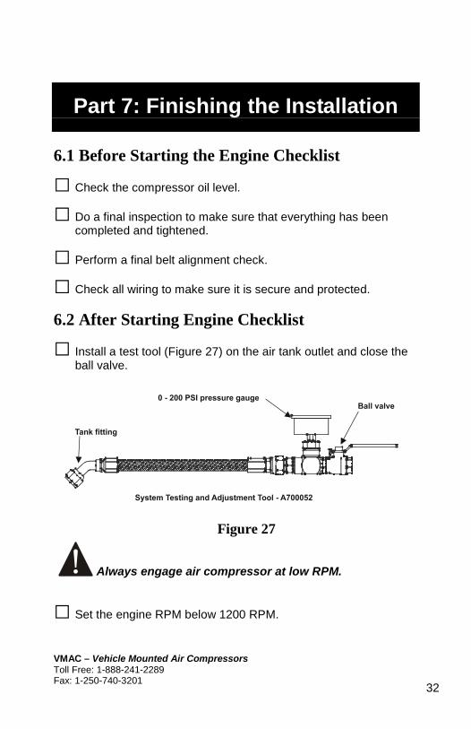
□ Install a test tool (Figure 27) on the air tank outlet and close the ball valve.
Figure 27
Always engage air compressor at low RPM.
□ Set the engine RPM below 1200 RPM.
VMAC – Vehicle Mounted Air Compressors Toll Free: 1-888-241-2289 Fax: 1-250-740-3201
32
□ Push the control box “ON” button. Adjust engine speed up to 2550 RPM.
□ Operate the system with an air tool or with the test tool for at least 15min.
□ Watch the engine operation to make sure that belts rotate properly and nothing is rubbing or contacting hot parts.
□ Check all components once the engine is turned off and the system has cooled.
□ Check the compressor oil level after the engine has been shut down and the oil level has had time to stabilize.
VMAC – Vehicle Mounted Air Compressors Toll Free: 1-888-241-2289 Fax: 1-250-740-3201
33

Accessory Products from VMAC
The following accessory products for your VR compressor system are available from VMAC. For more information or to order these products, call toll free 1-888-241-2289 or local 250-740-3200.
Eliminator Aftercooler Part Number A800070
Removes up to 80% of moisture from compressed air. Quick installation, automatic drain and compact design
Filter Regulator Lubricator Part Number A700151
Removes lubricants, water and dirt from the air stream. Adds atomized tool oil to lubricate tools. Reduces pressure for longer tool life.
Hose Reel Part Number A700007
Secure, compact, retractable hose storage in a sturdy reel.
Air Receiver Tank Part Number A300010
Thirty-five gallon capacity in a compact tank, complete with fittings and a gauge.
De-icer Kit Part Number A700031
Insulated rope heater prevents freezing of lines and regulator.
Service Kits VR70 500 hour A700205 VR70 1000 hour A700206 Using OEM service products will extend the life of your system. Includes oil, filters, seals and O-rings. 500 hour and 1000 hour service interval kits are available
34
Related Documents