DELTA DOORS MFG. A DIVISION OF VIDCO ALUMINUM INDUSTRIES INSTALLATION MANUAL DHS-500 IMPACT SYSTEM

Welcome message from author
This document is posted to help you gain knowledge. Please leave a comment to let me know what you think about it! Share it to your friends and learn new things together.
Transcript
DELTA DOORS MFG. A DIVISION OF VIDCO ALUMINUM INDUSTRIES
INSTALLATION MANUAL
DHS-500 IMPACT SYSTEM

DHS-500 Impact System Installation ManualTABLE OF CONTENTS
2
SECTION PAGE
GENERAL NOTES 3EXTRUSION & PARTS IDENTIFICATION 4-5DETERMINE FRAME SIZE 6 FABRICATE VERTICAL MULLIONS & FILLERS 7-8FABRICATE JAMB MULLIONS 9FABRICATE HEAD, HORIZONTAL & SILL MULLIONS 9ASSEMBLE FRAMES 10GLAZING 11-12INSTALL FRAMES 13ANCHOR FRAMES 14APPLY PERIMETER SEALANT 14APPLY EXTERIOR SEALANT 15
DELTA DOORS MFG. A DIVISION OF VIDCO ALUMINUM INDUSTRIES

DHS-500 Impact System Installation ManualGENERAL NOTES
3
HANDLING, STORING AND PROTECTION OF WINDOWS
Windows are a finished product and must be protected against damage. The following precautions are recommendedto assure early acceptance of your products and workmanship. A. HANDLE CAREFULLY - Do not drop or drag from the truck. Stack with adequate separation so windows will not rubtogether. Store off the ground Protect against the elements and other construction trades. Wear hand protection to prevent injury due to sharp edges of windows.
B. KEEP MATERIAL AWAY FROM WATER, MUD AND SPRAY - Prevent cement, plaster, or other materials from damaging finish.
C. PROTECT MATERIALS AFTER ERECTION - Protect by wrapping with Kraft paper or by erecting Visqueen or canvas splatter screen. Cement, plaster, terrazzo, other alkaline solutions and acid based materials used to cleanmasonry are very harmful to the finish and should be removed with water and mild soap IMMEDIATELY.
** CAUTION: WINDOWS ARE NOT TO BE USED AS LADDERS, SCAFFOLDS, OR SCAFFOLD SUPPORTS. **
GENERAL INSTALLATION NOTESThe following practices are recommended for all installations.
A. CHECK SHOP DRAWINGS, FABRICATION INSTRUCTIONS, ASSEMBLY & GLAZING INSTRUCTIONS, andINSTALLATION INSTRUCTIONS to become thoroughly familiar with the project. THE SHOP DRAWINGS take precedence and include specific details for the project. THE INSTALLATION INSTRUCTIONS are of a general natureand cover most common conditions.
B. All materials must be INSTALLED PLUMB, LEVEL, AND TRUE.
C. All work should start from bench marks and/or column lines as established by the ARCHITECTURAL DRAWINGSand the GENERAL CONTRACTOR.
D. Isolate all aluminum to be placed directly in contact with uncured masonry or incompatible materials with a heavy coat of zinc chromate or bituminous paint.
E. Check all materials on arrival for quantity and be sure you have everything required to begin installation.
F. Sealants must be compatible with all materials with which they have contact, including other sealant surfaces.Consult with sealant manufacturer for recommendations relative to joint size, shelf life, compatibility, priming, tooling,adhesion, etc.
G. PERIMETER FASTENING - "Fastening" means any method of securing one part to another or to adjacentmaterials. These instructions specify only those fasteners used within the system. Due to varying perimeter conditions and job performance requirements, anchor fasteners are not specified in these instructions. Refer to the Shop Drawings or consult a structural engineer for fastener type, sizing, and location.
H. CHECK OPENINGS - Make certain that the opening which will receive your materials is in accordance with the contract documents. If not, notify the General Contractor in writing and resolve differences before proceeding with your work.
I. BUILDING CODES - Glass and glazing codes governing the design and use of products vary widely. Delta Doorsdoes not control the selection of product configurations, operating hardware, or glazing materials, and assumes no responsibility for these design consideration. It is the responsibility of the owner, specifier, architect, general contractor and the installer to make these selections in strict conformance with all applicable codes.
DELTA DOORS MFG. A DIVISION OF VIDCO ALUMINUM INDUSTRIES

DHS-500 Impact System Installation ManualEXTRUSION IDENTIFICATION
4 DELTA DOORS MFG. A DIVISION OF VIDCO ALUMINUM INDUSTRIES
DLD-100JAMB/VERTICAL
DLD-101POCKET FILLER
DLD-102GLASS STOP
DLD-103HEAD/SILL
DLD-104HORIZONTAL
DLD-124JAMB (1 3/4" x 5")
BCE-475FLAT FILLER
DHS-500 Impact System Installation ManualPARTS IDENTIFICATION
5DELTA DOORS MFG. A DIVISION OF VIDCO ALUMINUM INDUSTRIES
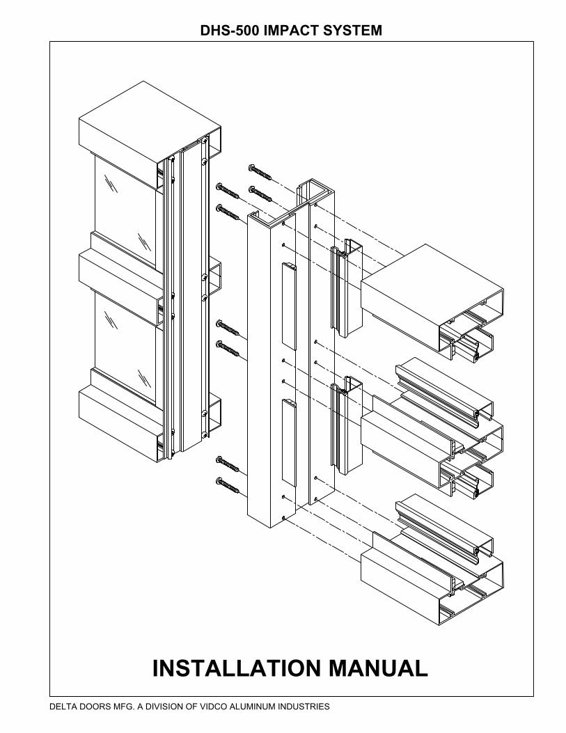
1350SETTING BLOCK
V-2106GLAZING TAPE
#7-14155GLAZING GASKET(USED WITH DLD-102)
MATERIAL - NEOPRENE1/8" x 3/4" x 2" LONG
NORTON GLAZING TAPETHERMABOND (3/16" x 1/4" x 50' ROLL)
MATERIAL - EPDM200' PER ROLL / 1000' PER BOX
ASSEMBLY SCREWS #12 x 1 3/4" PHSMS TYPE "AB"
BOLTS FORSTEEL REINFORCING
1/4"-20 x 2" HHMSWITH WASHER & LOCK NUT
STEEL REINFORCINGCHANNEL
15/16" x 4 5/8" (1/8" MINIMUM THICKNESS)

DHS-500 Impact System Installation Manual
6 DELTA DOORS MFG. A DIVISION OF VIDCO ALUMINUM INDUSTRIES
DETERMINE FRAME SIZE
STEP 1: Check the rough opening for correct size, squareness, and plumb as determined by tolerances listed in the architectural specifications and the shop drawings.
STEP 2: Measure the rough opening at the top, middle, and bottom. Select the smallest dimension measure and subtract 1/2" to determine the frame width.
STEP 3: Measure the height of the rough opening at several points along the opening. Select the smallest dimension and subtract 1/2" to determine the frame height.
NOTE: If project requires wood buck installation, determine measurements from wood buck.
FRAME WIDTH
OPENING WIDTH
OP
EN
ING
HE
IGH
T
FRA
ME
WID
TH
1/4"1/4"
1/4"
1/4"

DHS-500 Impact System Installation Manual
7DELTA DOORS MFG. A DIVISION OF VIDCO ALUMINUM INDUSTRIES
FABRICATE VERTICAL MULLIONS AND FILLERS
STEP 1: Cut all vertical mullions and vertical fillers to the frame height previously determined.
STEP 2: Notch vertical mullions and fillers as shown to accept horizontals.
STEP 3: Drill 0.236" (#B drill) clear holes at locations shown to accept horizontals.
NO
TCH
LE
G
3.81
2
0.68
6
1.4682.500
2.500 1.468
0.18
9
Leng
th
DLD-100
NO
TCH
LE
G
2.78
11.
372
0.18
9
NO
TCH
LE
G
2.78
11.
372
C/LHORIZ.
NO
TCH
LE
G
3.81
2
0.68
6
0.4712.500
2.500 0.471
0.18
9
Leng
th
NO
TCH
LE
G
2.7
81
1.37
2
0.18
9
NO
TCH
LE
G
2.7
81
1.37
2
C/LHORIZ.
0.20
3" D
IA.
TYP
.
DLD-101
0.23
6" D
IA.
TYP
.
1.90
6
1.90
6
1.90
6
0.68
6
0.68
6
1.90
6
DHS-500 Impact System Installation Manual
8 DELTA DOORS MFG. A DIVISION OF VIDCO ALUMINUM INDUSTRIES
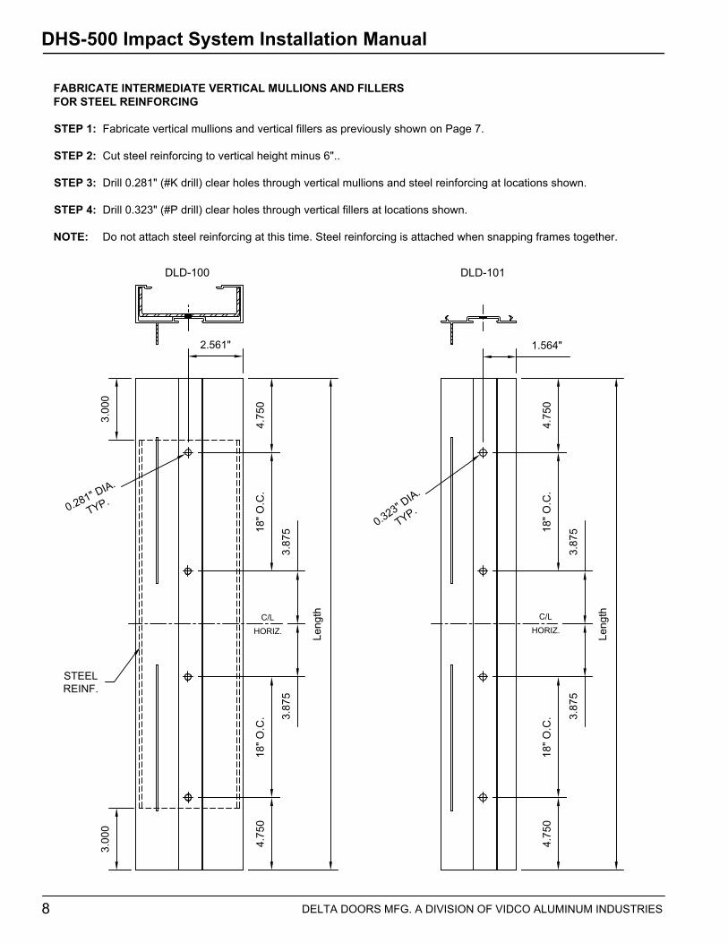
FABRICATE INTERMEDIATE VERTICAL MULLIONS AND FILLERSFOR STEEL REINFORCING
STEP 1: Fabricate vertical mullions and vertical fillers as previously shown on Page 7.
STEP 2: Cut steel reinforcing to vertical height minus 6"..
STEP 3: Drill 0.281" (#K drill) clear holes through vertical mullions and steel reinforcing at locations shown.
STEP 4: Drill 0.323" (#P drill) clear holes through vertical fillers at locations shown.
NOTE: Do not attach steel reinforcing at this time. Steel reinforcing is attached when snapping frames together.
18" O
.C.
3.87
53.
875
18" O
.C.
4.75
0
Leng
th
DLD-100
C/LHORIZ.
4.75
0
18" O
.C.
3.87
53.
875
18" O
.C.
4.75
0
Leng
thC/LHORIZ.
4.75
0
DLD-101
3.00
03.
000
STEELREINF.
2.561" 1.564"
0.323" DIA.
TYP.0.281" DIA.
TYP.

DHS-500 Impact System Installation Manual
9DELTA DOORS MFG. A DIVISION OF VIDCO ALUMINUM INDUSTRIES
FABRICATE JAMB MULLIONS
STEP 1: Cut all jamb mullions to the frame height.
STEP 2: Fabricate jamb mullions as shown on Page 7.
STEP 3: Install flat filler, BCE-475, at all anchor locations and stake the jamb legs to hold flat fillers in place.
STEP 4: Drill clear holes for anchor fasteners through jambmullion and flat fillers.
Refer to approved shop drawings or engineeringcalculations for anchor size and spacing.
FABRICATE HEAD, HORIZONTAL, & SILL MULLIONS
STEP 1: Cut head, horizontal, and sill mullions to DLObetween verticals.
STEP 2: Cut horizontal glass stops to DLO between verticals. Cut vertical glass stops to DLO between members minus 1 7/8". (Horizontal stops run through)
STEP 3: Drill clear holes for anchor fasteners in head & sill mullions.
Refer to approved shop drawings or engineeringcalculations for anchor size and spacing.
2.50
0
2.500
DLD-100JAMB
STAKELEG
ANCHOR HOLES
BCE-475FLAT FILLER

DHS-500 Impact System Installation Manual
10 DELTA DOORS MFG. A DIVISION OF VIDCO ALUMINUM INDUSTRIES
ASSEMBLE FRAMES
DHS-500 frames are assembled as individual bays that are later snapped together after they are glazed.
STEP 1: Clean horizontal ends and vertical members with isopropyl (50%) alcohol solution.
STEP 2: Apply silicone to each end of horizontal members as shown just prior to attaching to vertical members.
STEP 3: Attach horizontal members to vertical members through screw splines with #12 x 1 1/2" PHSMS fasteners.
STEP 4: Tool and wipe away excess silicone for a water tight joint.
STEP 5: Slip in steel reinforcing channel into DLD-100 vertical mullions.
SILICONE
SILICONE
#12 x 1 1/2"PPHSMS
DLD-100
DLD-101
DLD-103
DLD-103
DLD-104
DLD-100
STEELREINFORCING

DHS-500 Impact System Installation Manual
11DELTA DOORS MFG. A DIVISION OF VIDCO ALUMINUM INDUSTRIES
GLAZE FRAMES
DHS-500 frames must be bench glazed with frames lying down horizontally prior to being snapped together.
STEP 1: Clean frame glazing leg and glass surface with isopropyl (50%) alcohol solution.
STEP 2: Run and cut V-2106 Norton tape 1/4" from edge of glazing leg with horizontals running through as shown. Be careful not to stretch tape while installing.
STEP 3: Run 1/2" wide continuous bead of Dow Corning 995 silicone along glazing leg and behind glazing tape. Make sure silicone bead is continuous and contacts glazing tape.
STEP 4: Set setting blocks at sill at 1/8 points of DLO or according to engineering calculations as shown.
STEP 5: Calculate glass sizes: Glass Size = DLO – 3/8" (vertical and horizontal).
1/4"
V-2106 NORTON TAPE
1/2"
1/2" SILICONE
1/8 PTS. 1/8 PTS.
1350SETTING BLOCK
DAYLIGHT OPENING (DLO)
GLASS SIZE = DLO – 3/8"
DA
YLI
GH
T O
PE
NIN
G (D
LO)
GLA
SS
SIZ
E =
DLO
� 1
/2"

DHS-500 Impact System Installation Manual
12 DELTA DOORS MFG. A DIVISION OF VIDCO ALUMINUM INDUSTRIES
GLAZE FRAMES (CONTINUED)
STEP 6: Carefully set sill end of glass against setting blocks. Making sure glass is centered in opening, slowly lower glass into opening as shown.
STEP 7: Using a rubber mallet, tamp the glass edges against the glazing leg to ensure good adhesion.
STEP 8: To further ensure a good seal, tool sealant against frame and glass.
TOOLSILICONE
STEP 9: Cut 2" to 3" pieces of glass stop, DLD-102, loaded with glazing gasket to use as temporary stops.Install temporary stops at each end and 12" to 16" on center thereafter. Be careful not to cover perimeter anchor and steel reinforcing attachment holes.
Snap on glass stops, DLD-102, by engaging front hook and tapping down onto glass stop with a mallet and block of wood. Install horizontal stops first then vertical stops.
NOTE: Allow silicone to cure as recommended by sealant manufacturer before snapping frames together or standing frames up vertically.
TAP DOWNWITH MALLET
2" TO 3"
DLD-102GLASS STOP
HEAD SILL
HEAD SILL
BLOCKOF WOOD
DHS-500 Impact System Installation Manual
13DELTA DOORS MFG. A DIVISION OF VIDCO ALUMINUM INDUSTRIES
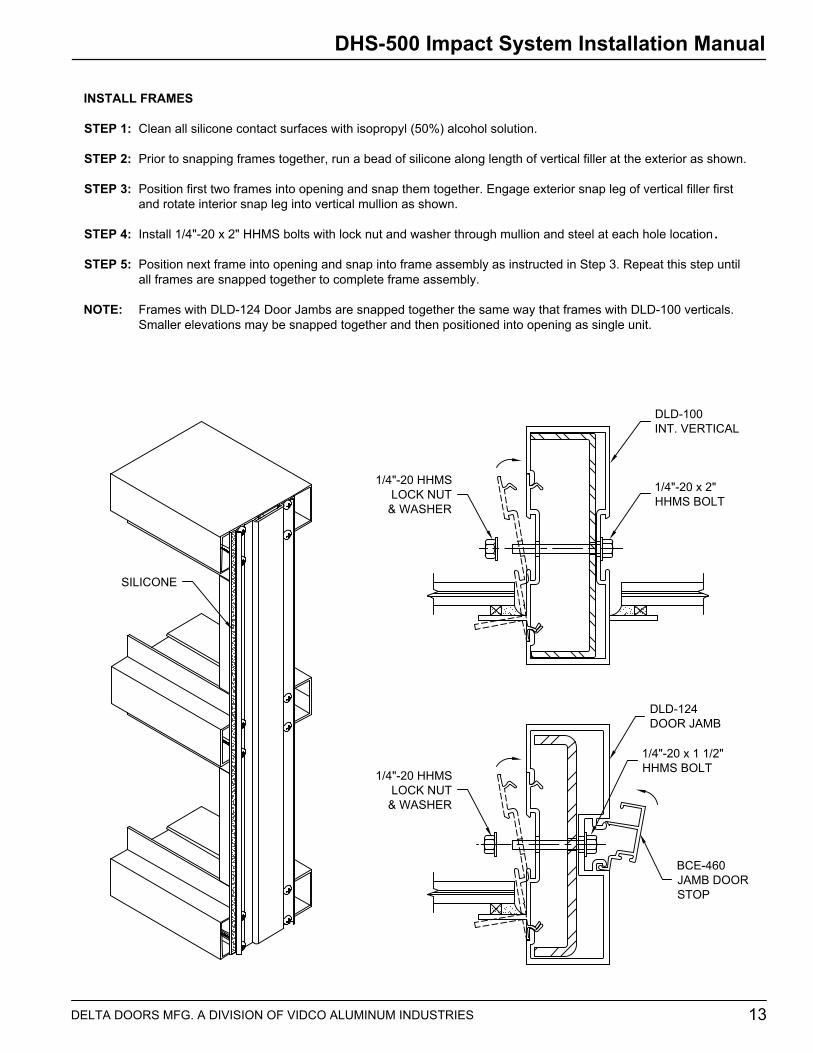
INSTALL FRAMES
STEP 1: Clean all silicone contact surfaces with isopropyl (50%) alcohol solution.
STEP 2: Prior to snapping frames together, run a bead of silicone along length of vertical filler at the exterior as shown.
STEP 3: Position first two frames into opening and snap them together. Engage exterior snap leg of vertical filler first and rotate interior snap leg into vertical mullion as shown.
STEP 4: Install 1/4"-20 x 2" HHMS bolts with lock nut and washer through mullion and steel at each hole location .
STEP 5: Position next frame into opening and snap into frame assembly as instructed in Step 3. Repeat this step until all frames are snapped together to complete frame assembly.
NOTE: Frames with DLD-124 Door Jambs are snapped together the same way that frames with DLD-100 verticals.Smaller elevations may be snapped together and then positioned into opening as single unit.
SILICONE
1/4"-20 x 2"HHMS BOLT
1/4"-20 HHMSLOCK NUT
& WASHER
1/4"-20 x 1 1/2"HHMS BOLT1/4"-20 HHMS
LOCK NUT& WASHER
DLD-124DOOR JAMB
BCE-460JAMB DOORSTOP
DLD-100INT. VERTICAL
DHS-500 Impact System Installation Manual
14 DELTA DOORS MFG. A DIVISION OF VIDCO ALUMINUM INDUSTRIES
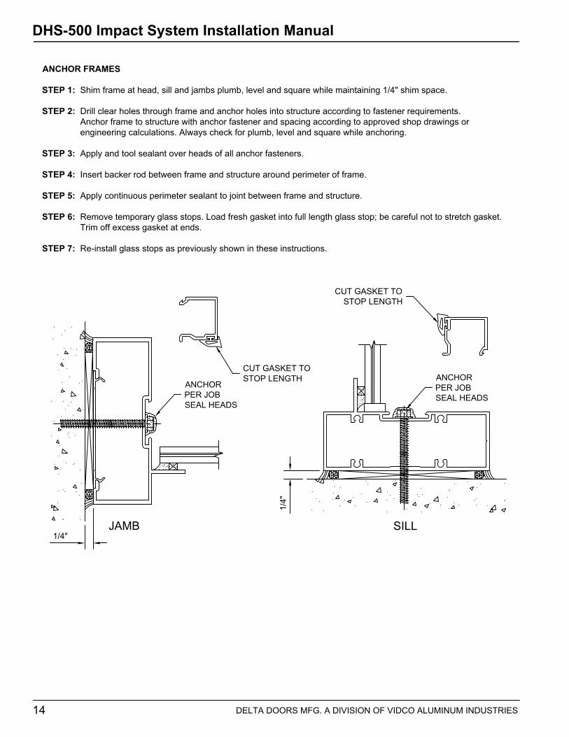
ANCHOR FRAMES
STEP 1: Shim frame at head, sill and jambs plumb, level and square while maintaining 1/4" shim space.
STEP 2: Drill clear holes through frame and anchor holes into structure according to fastener requirements.Anchor frame to structure with anchor fastener and spacing according to approved shop drawings or engineering calculations. Always check for plumb, level and square while anchoring.
STEP 3: Apply and tool sealant over heads of all anchor fasteners.
STEP 4: Insert backer rod between frame and structure around perimeter of frame.
STEP 5: Apply continuous perimeter sealant to joint between frame and structure.
STEP 6: Remove temporary glass stops. Load fresh gasket into full length glass stop; be careful not to stretch gasket. Trim off excess gasket at ends.
STEP 7: Re-install glass stops as previously shown in these instructions.
SILL
1/4"
1/4"JAMB
ANCHOR PER JOBSEAL HEADS
ANCHOR PER JOBSEAL HEADS
CUT GASKET TO STOP LENGTH
CUT GASKET TOSTOP LENGTH

DHS-500 Impact System Installation Manual
15DELTA DOORS MFG. A DIVISION OF VIDCO ALUMINUM INDUSTRIES
APPLY EXTERIOR SEALANT
STEP 1: The joint between the vertical and horizontal glazing legs must be sealed to ensure a water tight joint.Apply and tool sealant to all vertical to horizontal glazing leg joints and extend it to the glazing tape as shown.
STEP 2: Apply silicone cap bead around exterior glazing leg perimeter as shown. Make sure cap bead completely fills joint between glass and glazing leg.
APPLY & TOOLSEALANT SILICONE
CAP BEAD
SILICONECAP BEAD
Related Documents