ILD INSTALLATION MANUAL & CHECK-OFF SHEET 03/18

Welcome message from author
This document is posted to help you gain knowledge. Please leave a comment to let me know what you think about it! Share it to your friends and learn new things together.
Transcript
ILD
INSTALLATION MANUAL & CHECK-OFF SHEET
03/18

ILD PLUS Installation Manual
Document Part Number: 90-1113-200 / 13-680_90-00_02-00
ECN-M1186, Rev. 1.10, 03-05-18
Copyright © 2018 Palfinger Liftgates LLC.
All rights reserved.
Information in this document is subject to change without notice.
Visit www.palfinger.com for up to date information and notifications.
If you received this product with damaged or missing parts,
contact Palfinger Liftgates at (888)-774-5844
Parts Order
Technical Support
PALFINGER Liftgates, LLC.
15939 Piuma Ave.
Cerritos, CA 90703
Tel (888) 774-5844
Fax (562) 924-8318
PALFINGER Liftgates, LLC.
572 Whitehead Road.
Trenton, NJ 08619
Tel (609) 587-4200
Fax (609) 587-4201
ILD+ 33/44/55/66 Installation Manual
Revision 1.10 - 1 -
Table of Contents
1 Manual Updates ........................................................................................................................ - 4 -
2 Safety Information .................................................................................................................... - 5 -
3 Important Information ............................................................................................................... 6
4 Tools For Installation ................................................................................................................ 8
5 Parts List (all small parts can be found inside the Hydraulic Enclosure) ............................. 8
6 General View of Liftgate ........................................................................................................... 9
7 Installation Dimensions ............................................................................................................ 11
7.1 Important Dimensions ................................................................................................... 11
7.2 Installation Dimensions ................................................................................................. 14
7.3 Width Requirements ...................................................................................................... 15
7.4 Strength Requirements ................................................................................................. 16
8 Body Preparation ...................................................................................................................... 17
8.1 Rear Bumper ................................................................................................................. 17
8.2 Tow Hitch/Auxiliary Equipment ...................................................................................... 18
8.3 Flush the Sill (Sub-Framing) .......................................................................................... 19
8.4 Support Body ................................................................................................................ 22
9 Liftgate Preparation .................................................................................................................. 23
9.1 Liftgate Preparation ....................................................................................................... 23
9.2 Alignment Plates ........................................................................................................... 25
10 Standard Gate Mounting .......................................................................................................... 26
10.1 Mounting the Liftgate (Standard Installation) ................................................................. 26
10.2 Welding Liftgate ............................................................................................................ 32
11 Hydraulic Installation ................................................................................................................ 37
11.1 Hydraulic Enclosure ...................................................................................................... 37
11.2 Hydraulic Connections .................................................................................................. 39
11.3 Hydraulic Schematic ...................................................................................................... 49
11.3.1 Prior March 2018 ............................................................................................. 49
11.3.2 After March 2018 ............................................................................................. 50
11.4 Hydraulic Pump/Motor Overview ................................................................................... 51
11.5 Hydraulic Fluid .............................................................................................................. 52
12 Electrical Installation ................................................................................................................ 53
12.1 Auxiliary Battery Kit ....................................................................................................... 53
ILD+ 33/44/55/66 Installation Manual
Revision 1.10 - 2 -
12.2 Connecting Power to Control Board .............................................................................. 54
12.4 Battery Wiring – Truck and Trailer ................................................................................. 55
12.5 Cable Routing ............................................................................................................... 55
12.6 Wiring Crimping ............................................................................................................. 56
12.7 Circuit Breaker at Truck Batteries .................................................................................. 56
12.8 Battery Wiring – Truck Kit .............................................................................................. 57
12.9 Battery Wiring – Trailer Kit ............................................................................................. 59
12.10 Electrical Schematic ...................................................................................................... 61
12.10.1 Schematic (Prior to March 2018) ..................................................................... 61
12.10.2 Schematic (After to March 2018) ..................................................................... 62
12.11 Control Board System Codes ........................................................................................ 63
12.12 Trailer to Tractor Ground Test ....................................................................................... 64
12.13 Tail Light Harnesses ...................................................................................................... 65
12.14 Dock Bumper Installation............................................................................................... 65
13 Above Floor Liftgate Installation (Optional) ........................................................................... 66
13.1 Mounting the Liftgate ..................................................................................................... 66
13.2 Check Liftgate Dimensions ............................................................................................ 69
13.3 Welding Liftgate ............................................................................................................ 70
14 Lubrication ................................................................................................................................ 74
14.1 Standard Unit Lubrication Points ................................................................................... 75
14.2 Bottle Gas Unit Lubrication Points ................................................................................. 76
15 Decal Placement ....................................................................................................................... 77
16 Cycle Test and Bleed the System ............................................................................................ 80
16.1 Cycle Test and Bleed the hydraulic system, Standard Units .......................................... 80
16.2 Operating Instructions (Standard Units) ......................................................................... 80
16.3 Operating Instructions (Bottle Gas Units) ...................................................................... 85
17 Final Inspection Check List ...................................................................................................... 91

ILD+ 33/44/55/66 Installation Manual
Revision 1.10 - 3 -
Company Information: Company Name: Advisor Name: Trailer Year Make & Model:
Liftgate Information: Liftgate Serial Number: Liftgate Model Number: Date of Purchase: Date of Installation:
ILD+ 33/44/55/66 Installation Manual
Revision 1.10 - 4 -
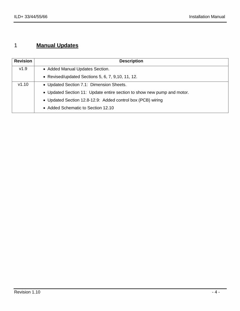
1 Manual Updates
Revision Description
v1.9 Added Manual Updates Section.
Revised/updated Sections 5, 6, 7, 9,10, 11, 12.
v1.10 Updated Section 7.1: Dimension Sheets.
Updated Section 11: Update entire section to show new pump and motor.
Updated Section 12.8-12.9: Added control box (PCB) wiring
Added Schematic to Section 12.10

ILD+ 33/44/55/66 Installation Manual
Revision 1.10 - 5 -
2 Safety Information
This manual follows the Guidelines set forth in “ANSI Z535.4-2007” for alerting you to possible hazards and their potential severity.
This is the safety alert symbol. It is used to alert you to potential personal injury hazards. Obey all safety messages that follow this symbol to avoid possible injury or death.
! DANGER indicates an imminently hazardous situation which, if not avoided, will result in death or serious injury.
! WARNING indicates potentially hazardous situation which, if not avoided, could result in death or serious injury.
! CAUTION indicates a potentially hazardous situation which, if not avoided, may result minor or moderate injury.
CAUTION without the safety alert symbol is used to address practices not related to personal injury. (In this manual we use it to alert you to potentially hazardous situation which, if not avoided, may result in property damage.)
NOTICE without the safety alert symbol is used to address practices not related to personal injury. (In this manual we use it to alert you to special instructions, steps, or procedures.)
ILD 35/44/55/66 Installation Manual
Revision 1.10 - 6 -
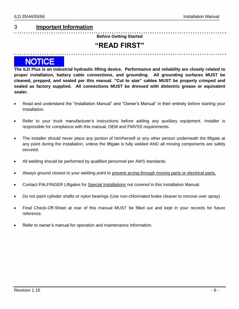
3 Important Information
Before Getting Started
“READ FIRST”
The ILD Plus is an industrial hydraulic lifting device. Performance and reliability are closely related to
proper installation, battery cable connections, and grounding. All grounding surfaces MUST be
cleaned, prepped, and sealed per this manual. “Cut to size” cables MUST be properly crimped and
sealed as factory supplied. All connections MUST be dressed with dielectric grease or equivalent
sealer.
Read and understand the “Installation Manual” and “Owner’s Manual” in their entirety before starting your
Installation.
Refer to your truck manufacturer’s instructions before adding any auxiliary equipment. Installer is
responsible for compliance with this manual, OEM and FMVSS requirements.
The installer should never place any portion of him/herself or any other person underneath the liftgate at
any point during the installation, unless the liftgate is fully welded AND all moving components are safely
secured.
All welding should be performed by qualified personnel per AWS standards.
Always ground closest to your welding point to prevent arcing through moving parts or electrical parts.
Contact PALFINGER Liftgates for Special Installations not covered in this Installation Manual.
Do not paint cylinder shafts or nylon bearings (Use non-chlorinated brake cleaner to remove over spray)
Final Check-Off-Sheet at rear of this manual MUST be filled out and kept in your records for future
reference.
Refer to owner’s manual for operation and maintenance information.
ILD 35/44/55/66 Installation Manual
Revision 1.10 - 7 -
Improper operation of this liftgate may result in severe personal injury or death. DO NOT operate
unless you have been properly instructed, have read and are familiar with the procedures in this
manual. This manual has been designed to illustrate the steps needed for the basic installation of the
ILD liftgate. It also provides safety information and simple preventive maintenance tips.
This manual is not intended for use as a repair or troubleshooting guide. Repairs should be performed
by a PALFINGER Liftgates Authorized Service Center.
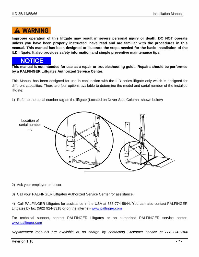
This Manual has been designed for use in conjunction with the ILD series liftgate only which is designed for
different capacities. There are four options available to determine the model and serial number of the installed
liftgate:
1) Refer to the serial number tag on the liftgate (Located on Driver Side Column- shown below)
2) Ask your employer or lessor.
3) Call your PALFINGER Liftgates Authorized Service Center for assistance.
4) Call PALFINGER Liftgates for assistance in the USA at 888-774-5844. You can also contact PALFINGER
Liftgates by fax (562) 924-8318 or on the internet- www.palfinger.com
For technical support, contact PALFINGER Liftgates or an authorized PALFINGER service center.
www.palfinger.com
Replacement manuals are available at no charge by contacting Customer service at 888-774-5844
Location of serial number
tag
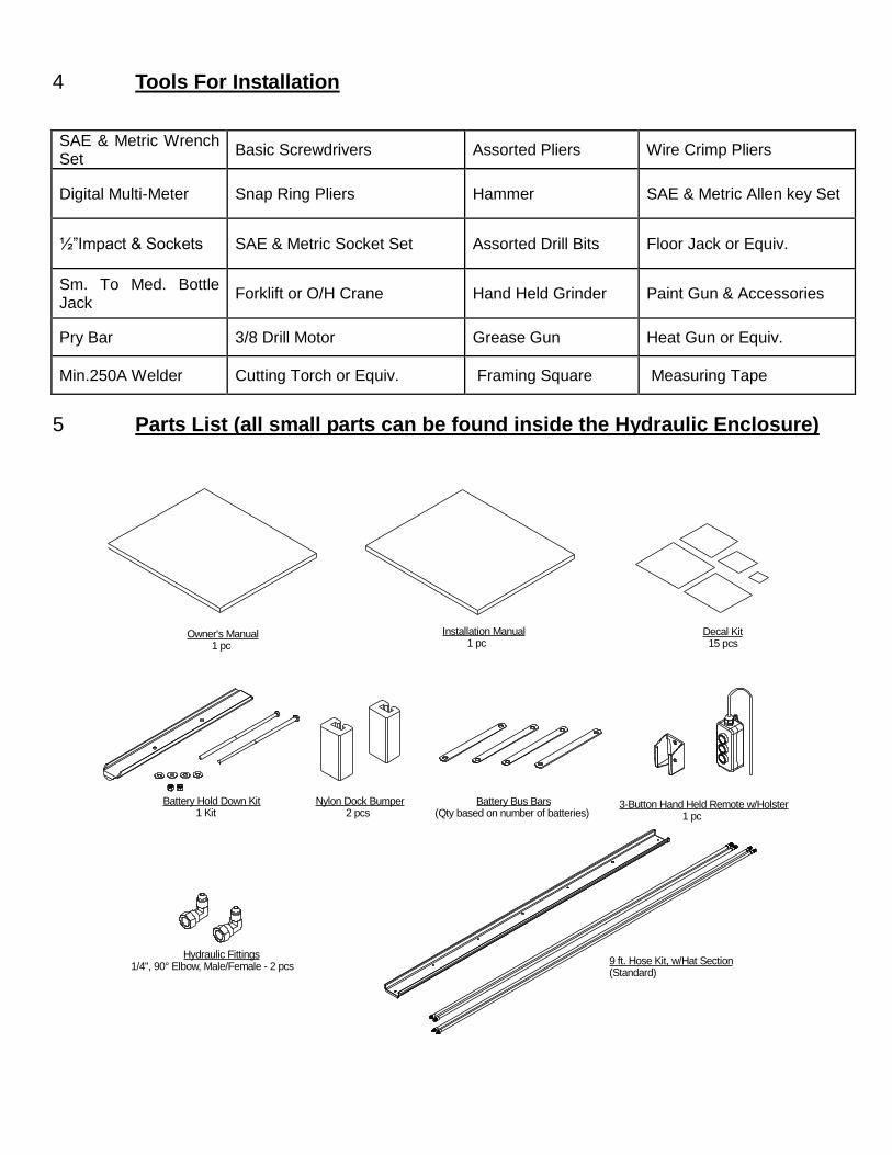
4 Tools For Installation
SAE & Metric Wrench Set
Basic Screwdrivers Assorted Pliers Wire Crimp Pliers
Digital Multi-Meter Snap Ring Pliers Hammer SAE & Metric Allen key Set
½”Impact & Sockets SAE & Metric Socket Set Assorted Drill Bits Floor Jack or Equiv.
Sm. To Med. Bottle Jack
Forklift or O/H Crane Hand Held Grinder Paint Gun & Accessories
Pry Bar 3/8 Drill Motor Grease Gun Heat Gun or Equiv.
Min.250A Welder Cutting Torch or Equiv. Framing Square Measuring Tape
5 Parts List (all small parts can be found inside the Hydraulic Enclosure)
Battery Bus Bars(Qty based on number of batteries)
Owner's Manual 1 pc
Installation Manual 1 pc
Decal Kit 15 pcs
Battery Hold Down Kit 1 Kit
Nylon Dock Bumper 2 pcs
3-Button Hand Held Remote w/Holster 1 pc
Hydraulic Fittings1/4", 90° Elbow, Male/Female - 2 pcs
9 ft. Hose Kit, w/Hat Section(Standard)
ILD 35/44/55/66 Installation Manual
Revision 1.10 - 9 -
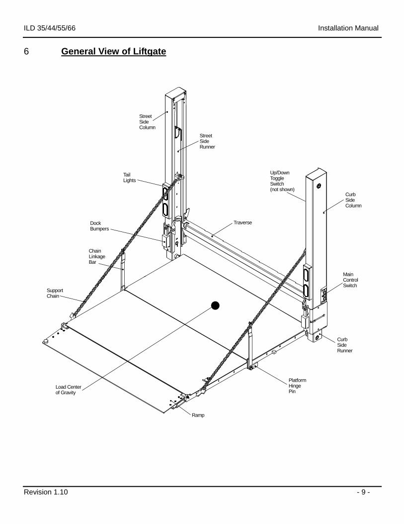
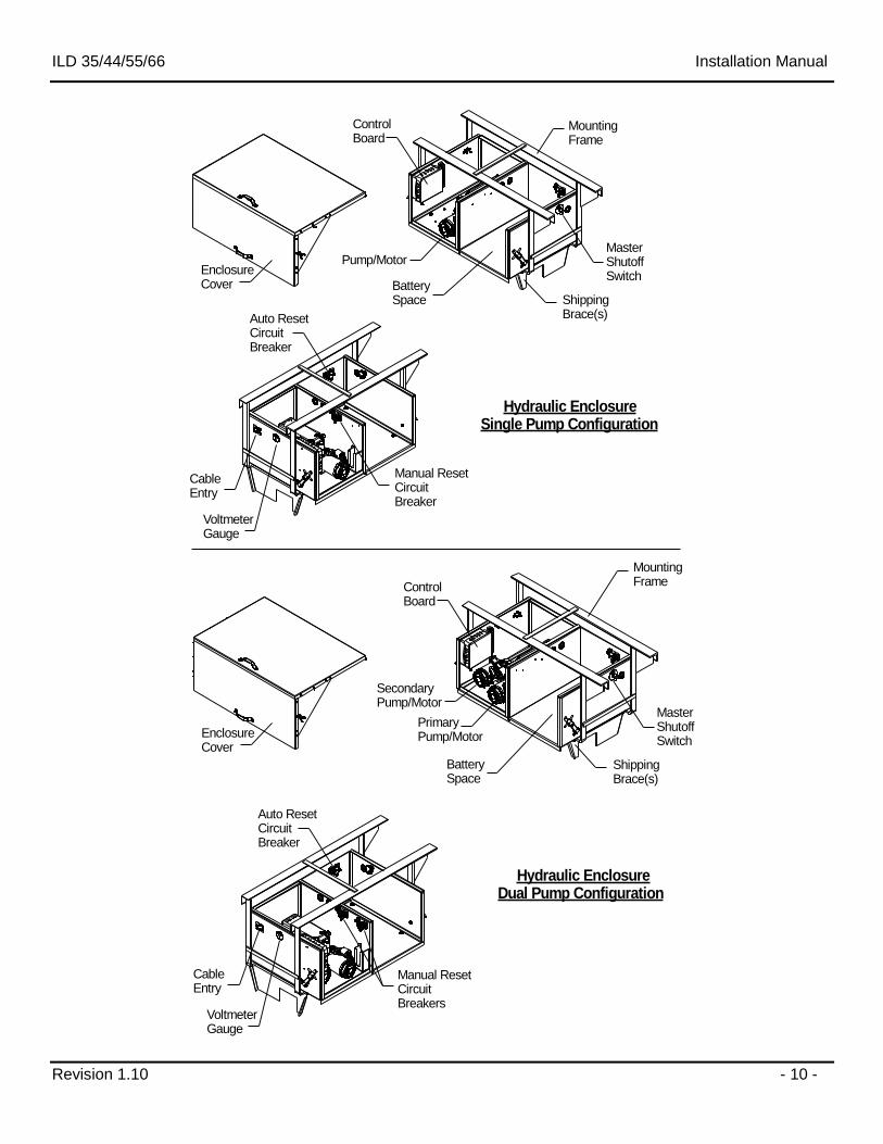
6 General View of Liftgate
Support Chain
ChainLinkageBar
Ramp
Load Centerof Gravity
PlatformHingePin
CurbSide Runner
Main ControlSwitch
CurbSideColumn
StreetSideColumn
Traverse
StreetSide Runner
Dock Bumpers
TailLights
Up/DownToggleSwitch (not shown)
ILD 35/44/55/66 Installation Manual
Revision 1.10 - 10 -
Pump/Motor
ControlBoard
EnclosureCover
ShippingBrace(s)
MountingFrame
MasterShutoffSwitch
VoltmeterGauge
CableEntry
BatterySpace
Hydraulic EnclosureSingle Pump Configuration
Hydraulic EnclosureDual Pump Configuration
Manual ResetCircuit Breakers
Auto ResetCircuit Breaker
VoltmeterGauge
CableEntry
ShippingBrace(s)
MasterShutoffSwitch
PrimaryPump/Motor
BatterySpace
SecondaryPump/Motor
ControlBoard
MountingFrame
EnclosureCover
Auto ResetCircuit Breaker
Manual ResetCircuit Breaker
ILD 35/44/55/66 Installation Manual
Revision 1.10 - 11 -
7 Installation Dimensions
7.1 Important Dimensions
Minimum Bed Height dimensions are ALWAYS MAXIMUM LOADED TRUCK.
Maximum Bed Height dimensions are ALWAYS DRY UNLOADED TRUCK.
Ensure truck body or trailer rear door does not interfere with installation or operation of ILD plus series liftgate.
The ILD plus series cannot be installed with "barn" or "swing" type doors without extensive modification.
It is not recommended to cut, torch, or remove support materials from rear sill of truck or trailer. Installers are
advised to sub-frame or flush sills as required. Removing gussets, stiffeners, light rings, or other such support
structures may VOID your truck/trailer warranty.
Call tech support before starting the installation if you have any questions or concerns on mounting dimensions
or procedures 888-774-5844
ILD 35/44/55/66 Installation Manual
Revision 1.10 - 12 -
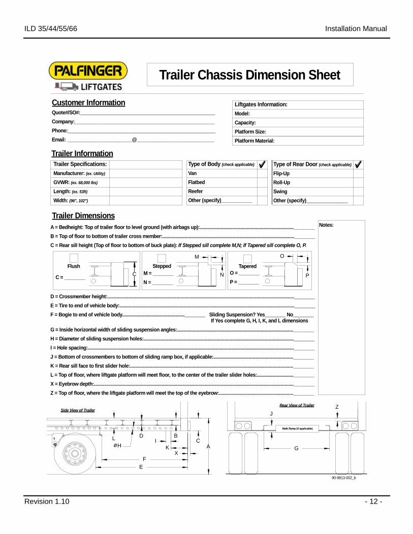
A = Bedheight: Top of trailer floor to level ground (with airbags up):........................................................................________
B = Top of floor to bottom of trailer cross member:.....................................................................................................________
C = Rear sill height (Top of floor to bottom of buck plate): If Stepped sill complete M,N; If Tapered sill complete O, P.
D = Crossmember height:...............................................................................................................................................________ .
E = Tire to end of vehicle body:......................................................................................................................................________
F = Bogie to end of vehicle body................................................________ Sliding Suspension? Yes________ No________ If Yes complete G, H, I, K, and L dimensions
G = Inside horizontal width of sliding suspension angles:.........................................................................................________
H = Diameter of sliding suspension holes:...................................................................................................................________ .
I = Hole spacing:..............................................................................................................................................................________
J = Bottom of crossmembers to bottom of sliding ramp box, if applicable:.............................................................________
K = Rear sill face to first slider hole:.............................................................................................................................________
L = Top of floor, where liftgate platform will meet floor, to the center of the trailer slider holes:............................________
X = Eyebrow depth:.........................................................................................................................................................________
Z = Top of floor, where the liftgate platform will meet the top of the eyebrow:.........................................................________
Customer Information
Quote#/SO#:____________________________________________________
Company:______________________________________________________
Phone:_________________________________________________________
Email: _________________________@______________________________
Trailer Information
Trailer Dimensions
Type of Body (check applicable)
Van
Flatbed
Reefer
Other (specify)____________
Type of Rear Door (check applicable)
Flip-Up
Roll-Up
Swing
Other (specify)________________
Trailer Specifications:
Manufacturer: (ex. Utility)
GVWR: (ex. 68,000 lbs)
Length: (ex. 53ft)
Width: (96", 102")
Trailer Chassis Dimension Sheet
Liftgates Information:
Model:
Capacity:
Platform Size:
Platform Material:
90-9813-002_b
Flush Stepped Tapered
M = ________
N = ________
O = ________
P = ________
A
BC
D
E
F
G
Side View of TrailerRear View of Trailer
X
Z
L
KøHI
Walk Ramp (if applicable)
J
M
N
O
P
Notes:
CC = ________
ILD 35/44/55/66 Installation Manual
Revision 1.10 - 13 -
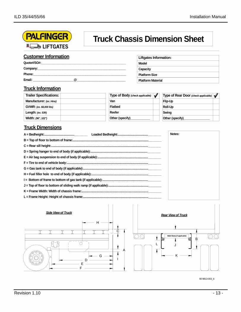
A = Bedheight:.....................................________ Loaded Bedheight:.....................................________
B = Top of floor to bottom of frame:.............................................................................................________
C = Rear sill height:.......................................................................................................................________
D = Spring hanger to end of body (if applicable):......................................................................________
E = Air bag suspension to end of body (if applicable):..............................................................________
F = Tire to end of vehicle body:....................................................................................................________
G = Gas tank to end of body (if applicable):................................................................................________
H = Fuel filler hole to end of body (if applicable):......................................................................________
I = Bottom of frame to bottom of gas tank (if applicable):........................................................________
J = Top of floor to bottom of sliding walk ramp (if applicable):.................................................________
K = Frame Width: Width of chassis frame:..................................................................................________
L = Frame Height: Height of chassis frame:................................................................................________
Truck Information
Truck Dimensions
Type of Body (check applicable)
Van
Flatbed
Reefer
Other (specify)____________
Type of Rear Door (check applicable)
Flip-Up
Roll-Up
Swing
Other (specify)________________
Trailer Specifications:
Manufacturer: (ex. Hino)
GVWR: (ex. 68,000 lbs)
Length: (ex. 53ft)
Width: (96", 102")
Truck Chassis Dimension Sheet
Liftgates Information:
Model
Capacity
Platform Size
Platform Material
90-9813-003_b
Notes:
Side View of TruckRear View of Truck
Walk Ramp (if applicable)
A
B
C
DE
F
G
J
H
IK
L
Customer Information
Quote#/SO#:____________________________________________________
Company:______________________________________________________
Phone:_________________________________________________________
Email: _________________________@______________________________
ILD 35/44/55/66 Installation Manual
Revision 1.10 - 14 -
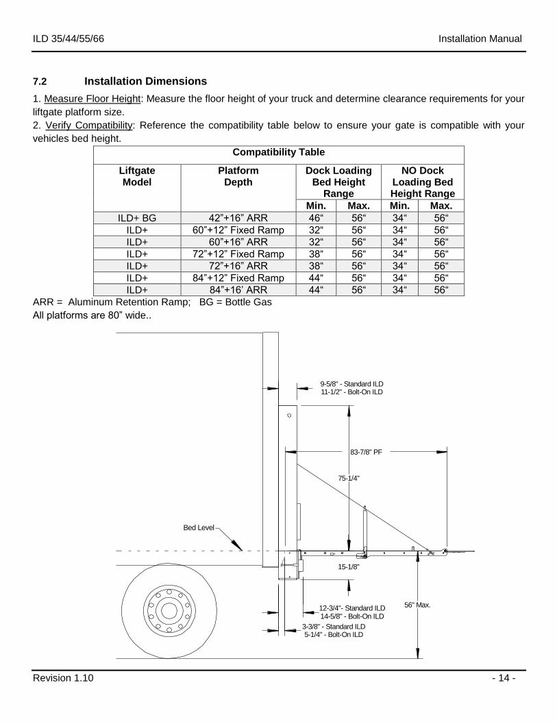
7.2 Installation Dimensions
1. Measure Floor Height: Measure the floor height of your truck and determine clearance requirements for your
liftgate platform size.
2. Verify Compatibility: Reference the compatibility table below to ensure your gate is compatible with your
vehicles bed height.
Compatibility Table
Liftgate Model
Platform Depth
Dock Loading Bed Height
Range
NO Dock Loading Bed Height Range
Min. Max. Min. Max.
ILD+ BG 42”+16” ARR 46“ 56“ 34“ 56“
ILD+ 60”+12” Fixed Ramp 32“ 56“ 34“ 56“
ILD+ 60”+16” ARR 32“ 56“ 34“ 56“
ILD+ 72”+12” Fixed Ramp 38“ 56“ 34“ 56“
ILD+ 72”+16” ARR 38“ 56“ 34“ 56“
ILD+ 84”+12” Fixed Ramp 44“ 56“ 34“ 56“
ILD+ 84”+16’ ARR 44“ 56“ 34“ 56“
ARR = Aluminum Retention Ramp; BG = Bottle Gas
All platforms are 80” wide..
56" Max.
75-1/4"
Bed Level
83-7/8" PF
9-5/8" - Standard ILD11-1/2" - Bolt-On ILD
15-1/8"
12-3/4"- Standard ILD14-5/8" - Bolt-On ILD
3-3/8" - Standard ILD5-1/4" - Bolt-On ILD
ILD 35/44/55/66 Installation Manual
Revision 1.10 - 15 -
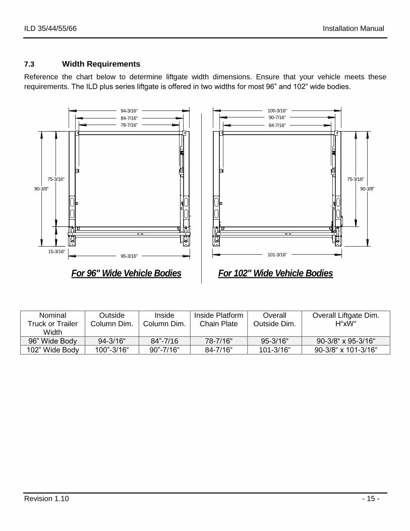
7.3 Width Requirements
Reference the chart below to determine liftgate width dimensions. Ensure that your vehicle meets these
requirements. The ILD plus series liftgate is offered in two widths for most 96” and 102” wide bodies.
94-3/16" 100-3/16"
75-3/16"
For 102" Wide Vehicle BodiesFor 96" Wide Vehicle Bodies
75-3/16"
15-3/16"
90-7/16"84-7/16"
95-3/16" 101-3/16"
84-7/16"78-7/16"
90-3/8" 90-3/8"
Nominal Truck or Trailer
Width
Outside Column Dim.
Inside Column Dim.
Inside Platform Chain Plate
Overall Outside Dim.
Overall Liftgate Dim. H“xW“
96” Wide Body 94-3/16“ 84”-7/16 78-7/16“ 95-3/16“ 90-3/8“ x 95-3/16“
102” Wide Body 100”-3/16“ 90”-7/16“ 84-7/16“ 101-3/16“ 90-3/8“ x 101-3/16“
ILD 35/44/55/66 Installation Manual
Revision 1.10 - 16 -
Z
Z
Y
Y
X
X
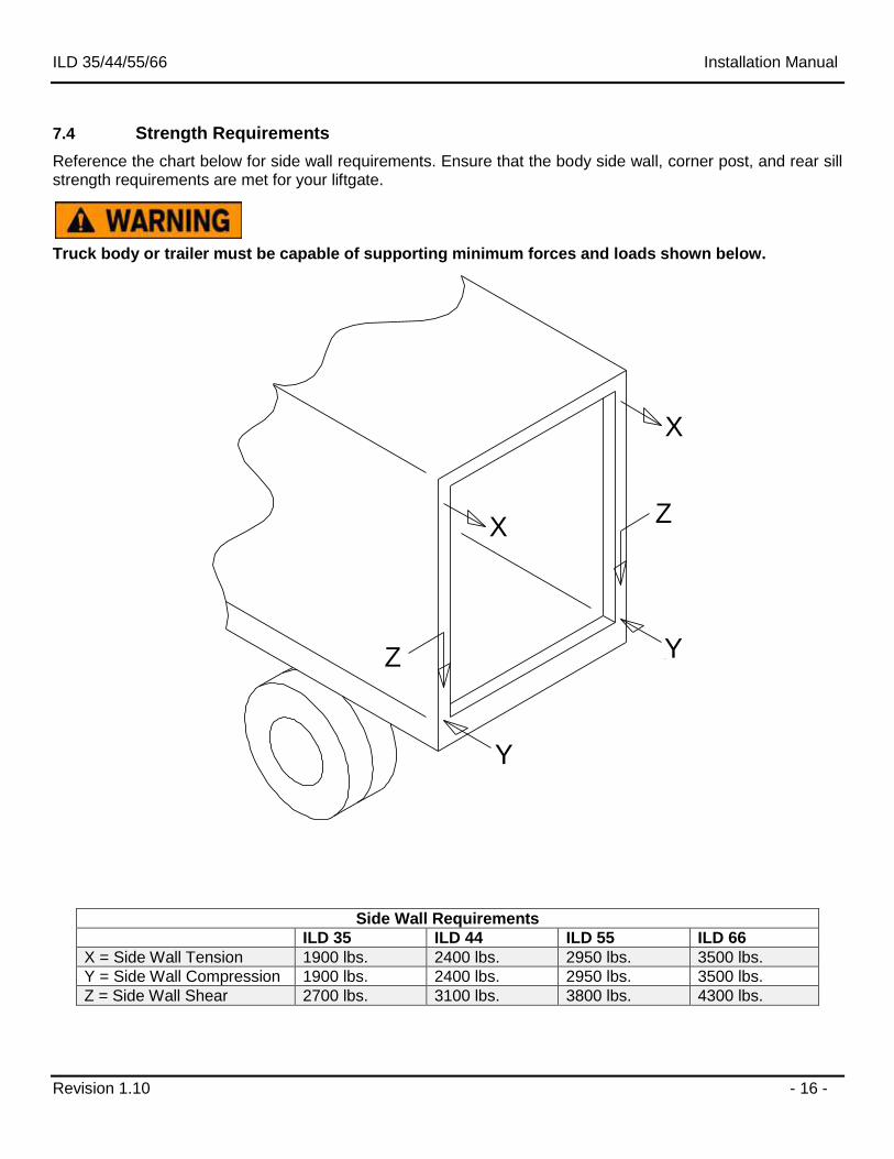
7.4 Strength Requirements
Reference the chart below for side wall requirements. Ensure that the body side wall, corner post, and rear sill strength requirements are met for your liftgate.
Truck body or trailer must be capable of supporting minimum forces and loads shown below.
Side Wall Requirements
ILD 35 ILD 44 ILD 55 ILD 66
X = Side Wall Tension 1900 lbs. 2400 lbs. 2950 lbs. 3500 lbs.
Y = Side Wall Compression 1900 lbs. 2400 lbs. 2950 lbs. 3500 lbs.
Z = Side Wall Shear 2700 lbs. 3100 lbs. 3800 lbs. 4300 lbs.
ILD 35/44/55/66 Installation Manual
Revision 1.10 - 17 -
8 Body Preparation
In order to install your ILD series liftgate, some body preparation may be required. Truck and trailer
applications with flush corner post and sill and NO protruding gussets or stiffeners are the most straight
forward of all ILD installations. Rear of body should be 90° to ground.
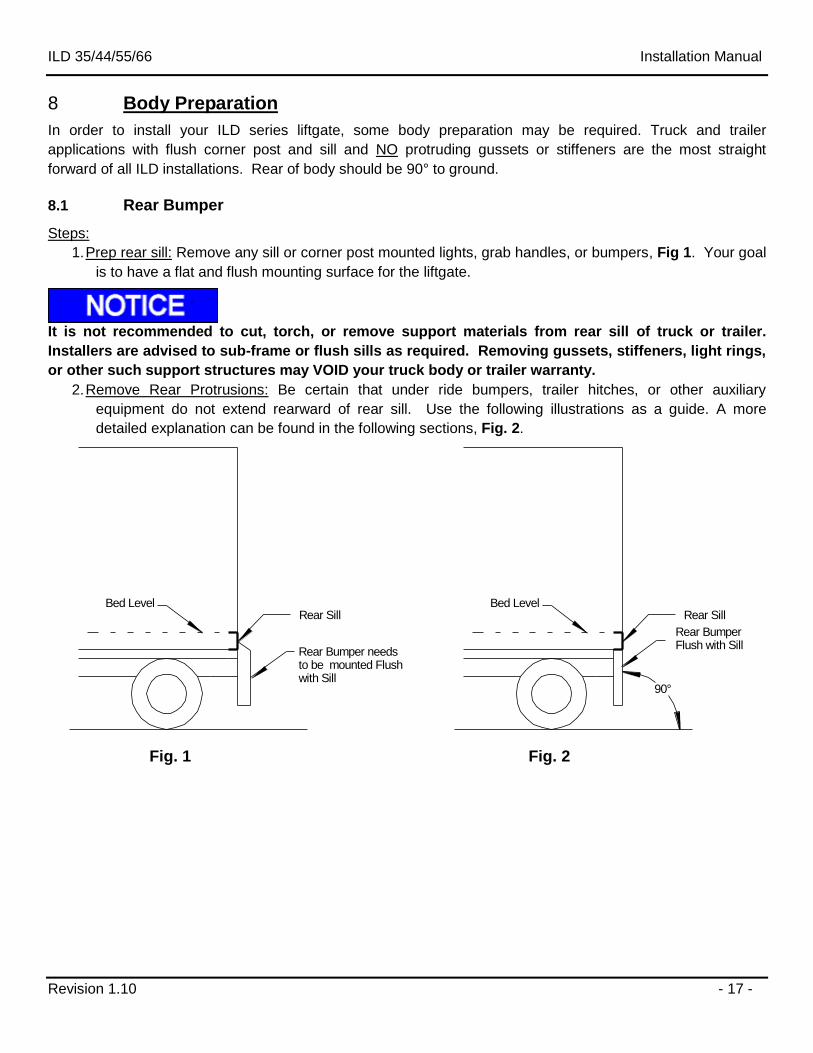
8.1 Rear Bumper
Steps:
1. Prep rear sill: Remove any sill or corner post mounted lights, grab handles, or bumpers, Fig 1. Your goal
is to have a flat and flush mounting surface for the liftgate.
It is not recommended to cut, torch, or remove support materials from rear sill of truck or trailer.
Installers are advised to sub-frame or flush sills as required. Removing gussets, stiffeners, light rings,
or other such support structures may VOID your truck body or trailer warranty.
2. Remove Rear Protrusions: Be certain that under ride bumpers, trailer hitches, or other auxiliary
equipment do not extend rearward of rear sill. Use the following illustrations as a guide. A more
detailed explanation can be found in the following sections, Fig. 2.
Bed LevelRear Sill
Rear Bumper needs to be mounted Flush with Sill
Bed LevelRear Sill
Rear Bumper Flush with Sill
90°
Fig. 1 Fig. 2
ILD 35/44/55/66 Installation Manual
Revision 1.10 - 18 -
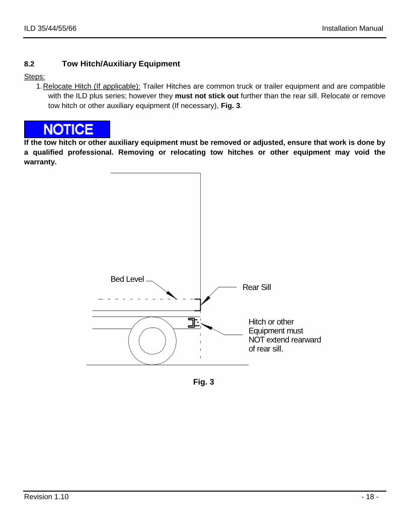
8.2 Tow Hitch/Auxiliary Equipment
Steps:
1. Relocate Hitch (If applicable): Trailer Hitches are common truck or trailer equipment and are compatible
with the ILD plus series; however they must not stick out further than the rear sill. Relocate or remove
tow hitch or other auxiliary equipment (If necessary), Fig. 3.
If the tow hitch or other auxiliary equipment must be removed or adjusted, ensure that work is done by
a qualified professional. Removing or relocating tow hitches or other equipment may void the
warranty.
Bed LevelRear Sill
Hitch or other Equipment must NOT extend rearward of rear sill.
Fig. 3
ILD 35/44/55/66 Installation Manual
Revision 1.10 - 19 -
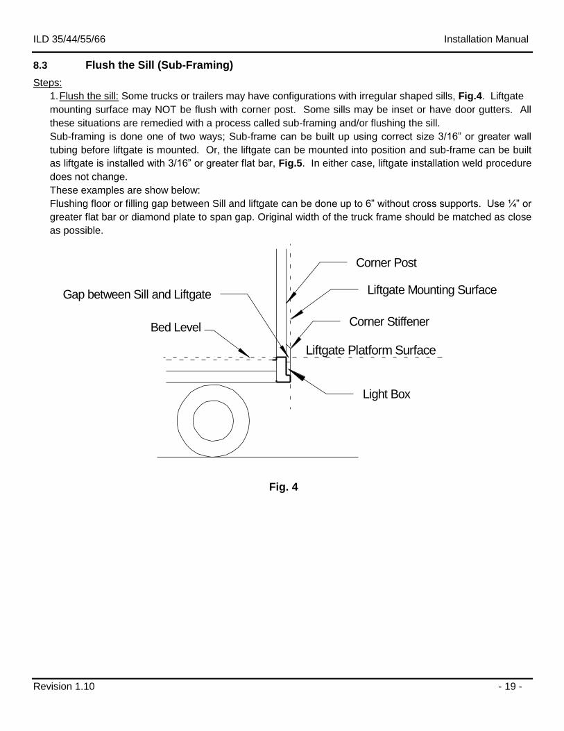
8.3 Flush the Sill (Sub-Framing)
Steps:
1. Flush the sill: Some trucks or trailers may have configurations with irregular shaped sills, Fig.4. Liftgate
mounting surface may NOT be flush with corner post. Some sills may be inset or have door gutters. All
these situations are remedied with a process called sub-framing and/or flushing the sill.
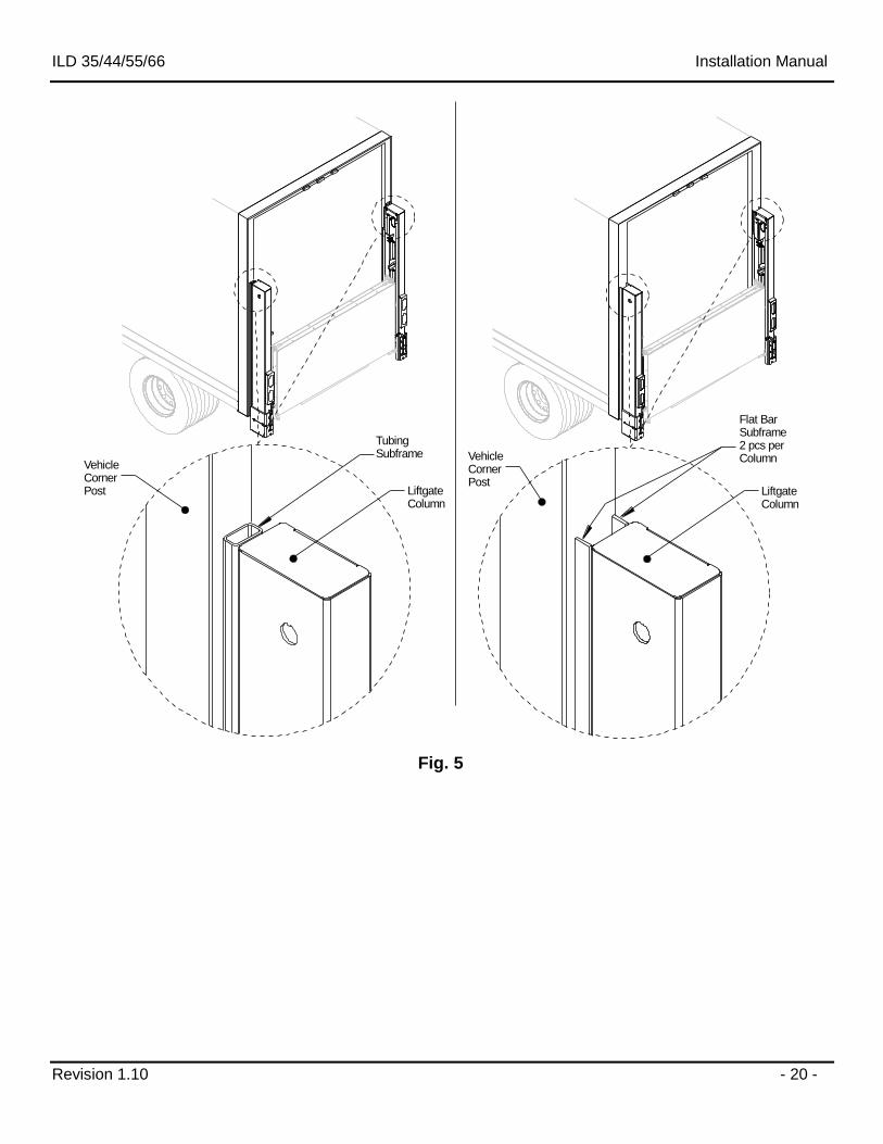
Sub-framing is done one of two ways; Sub-frame can be built up using correct size 3/16” or greater wall
tubing before liftgate is mounted. Or, the liftgate can be mounted into position and sub-frame can be built
as liftgate is installed with 3/16” or greater flat bar, Fig.5. In either case, liftgate installation weld procedure
does not change.
These examples are show below:
Flushing floor or filling gap between Sill and liftgate can be done up to 6” without cross supports. Use ¼” or
greater flat bar or diamond plate to span gap. Original width of the truck frame should be matched as close
as possible.
Bed Level Corner Stiffener
Light Box
Corner Post
Liftgate Mounting Surface
Liftgate Platform Surface
Gap between Sill and Liftgate
Fig. 4
ILD 35/44/55/66 Installation Manual
Revision 1.10 - 20 -
TubingSubframe
Flat BarSubframe2 pcs perColumn
LiftgateColumn
VehicleCornerPost Liftgate
Column
VehicleCornerPost
Fig. 5
ILD 35/44/55/66 Installation Manual
Revision 1.10 - 21 -
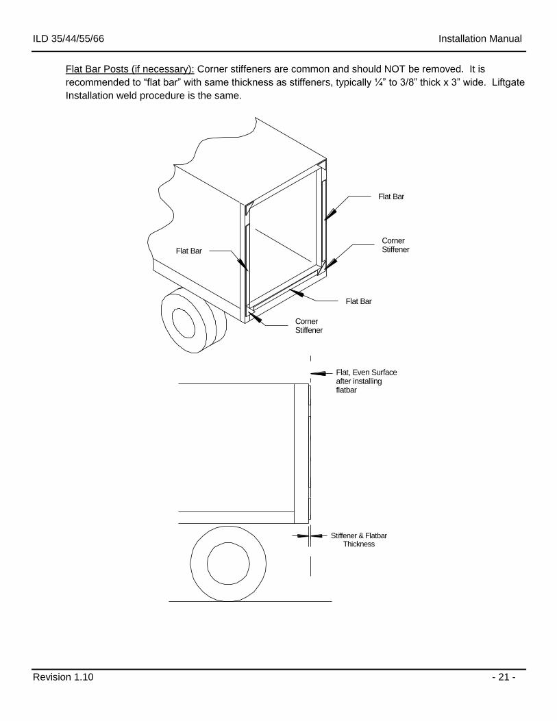
Flat Bar Posts (if necessary): Corner stiffeners are common and should NOT be removed. It is
recommended to “flat bar” with same thickness as stiffeners, typically ¼” to 3/8” thick x 3” wide. Liftgate
Installation weld procedure is the same.
Corner Stiffener
Corner Stiffener
Flat Bar
Flat Bar
Flat Bar
Flat, Even Surfaceafter installingflatbar
Stiffener & FlatbarThickness
ILD 35/44/55/66 Installation Manual
Revision 1.10 - 22 -
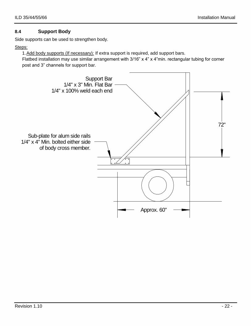
8.4 Support Body
Side supports can be used to strengthen body.
Steps:
1. Add body supports (If necessary): If extra support is required, add support bars.
Flatbed installation may use similar arrangement with 3/16” x 4” x 4”min. rectangular tubing for corner
post and 3” channels for support bar.
72"
Approx. 60"
Support Bar1/4" x 3" Min. Flat Bar
1/4" x 100% weld each end
Sub-plate for alum side rails1/4" x 4" Min. bolted either side
of body cross member.
ILD 35/44/55/66 Installation Manual
Revision 1.10 - 23 -
9 Liftgate Preparation
The installer should never position any portion of him/herself, or any other person directly under the
liftgate at any point during gate mounting.
9.1 Liftgate Preparation
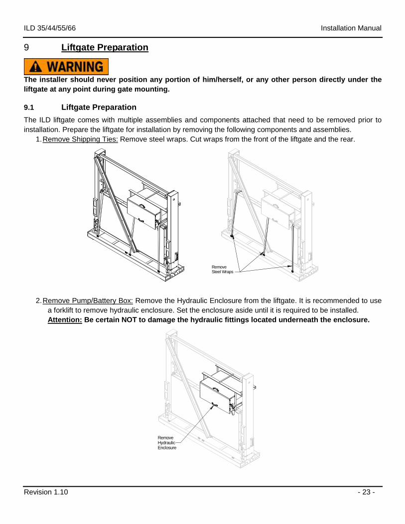
The ILD liftgate comes with multiple assemblies and components attached that need to be removed prior to
installation. Prepare the liftgate for installation by removing the following components and assemblies.
1. Remove Shipping Ties: Remove steel wraps. Cut wraps from the front of the liftgate and the rear.
RemoveSteel Wraps
2. Remove Pump/Battery Box: Remove the Hydraulic Enclosure from the liftgate. It is recommended to use
a forklift to remove hydraulic enclosure. Set the enclosure aside until it is required to be installed.
Attention: Be certain NOT to damage the hydraulic fittings located underneath the enclosure.
RemoveHydraulicEnclosure
ILD 35/44/55/66 Installation Manual
Revision 1.10 - 24 -
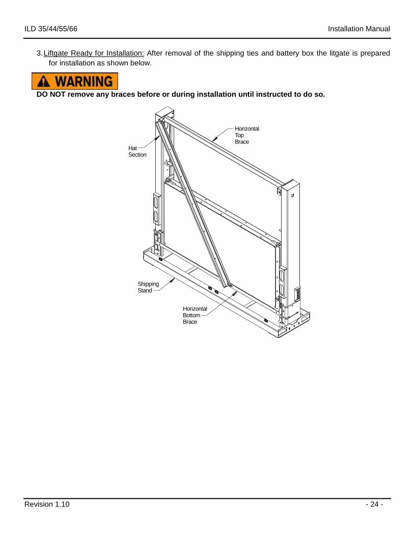
3. Liftgate Ready for Installation: After removal of the shipping ties and battery box the litgate is prepared
for installation as shown below.
DO NOT remove any braces before or during installation until instructed to do so.
ShippingStand
HorizontalBottomBrace
HorizontalTopBrace
HatSection
ILD 35/44/55/66 Installation Manual
Revision 1.10 - 25 -
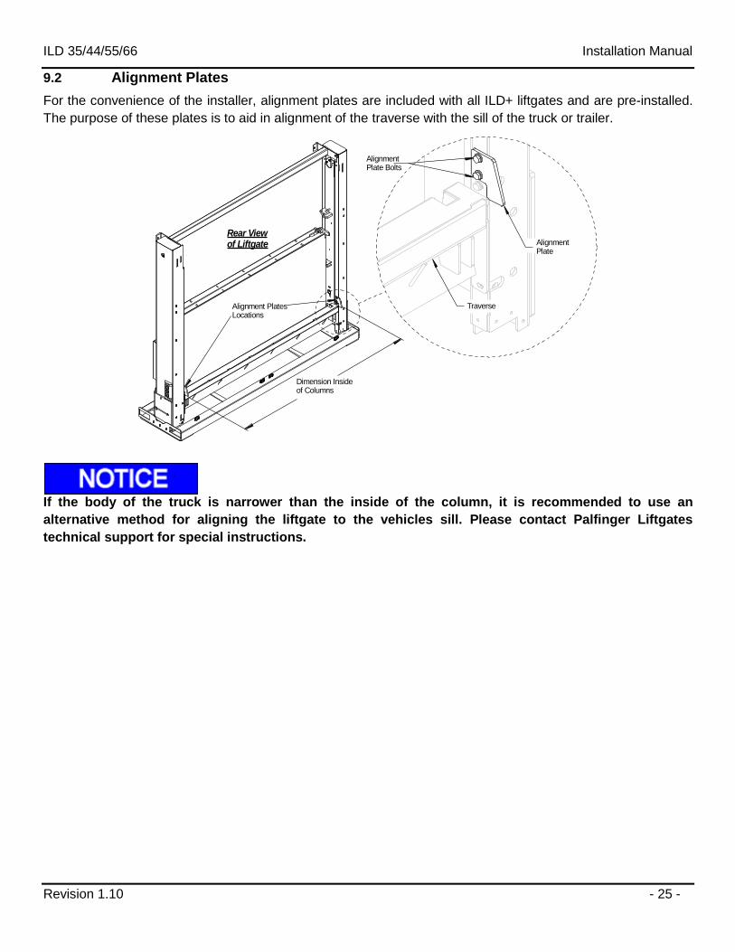
9.2 Alignment Plates
For the convenience of the installer, alignment plates are included with all ILD+ liftgates and are pre-installed.
The purpose of these plates is to aid in alignment of the traverse with the sill of the truck or trailer.
Rear Viewof Liftgate Alignment
Plate
Traverse
Dimension Insideof Columns
Alignment PlatesLocations
AlignmentPlate Bolts
If the body of the truck is narrower than the inside of the column, it is recommended to use an
alternative method for aligning the liftgate to the vehicles sill. Please contact Palfinger Liftgates
technical support for special instructions.
ILD 35/44/55/66 Installation Manual
Revision 1.10 - 26 -
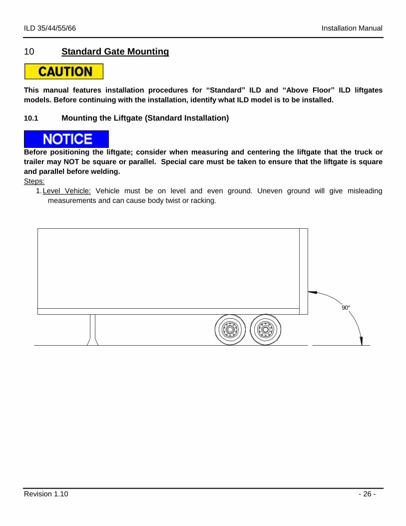
10 Standard Gate Mounting
This manual features installation procedures for “Standard” ILD and “Above Floor” ILD liftgates
models. Before continuing with the installation, identify what ILD model is to be installed.
10.1 Mounting the Liftgate (Standard Installation)
Before positioning the liftgate; consider when measuring and centering the liftgate that the truck or
trailer may NOT be square or parallel. Special care must be taken to ensure that the liftgate is square
and parallel before welding.
Steps:
1. Level Vehicle: Vehicle must be on level and even ground. Uneven ground will give misleading
measurements and can cause body twist or racking.
90°
ILD 35/44/55/66 Installation Manual
Revision 1.10 - 27 -
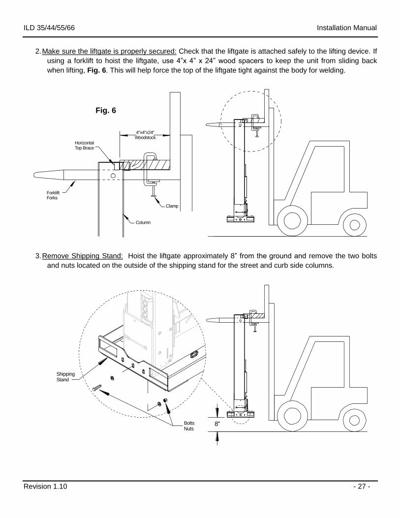
2. Make sure the liftgate is properly secured: Check that the liftgate is attached safely to the lifting device. If
using a forklift to hoist the liftgate, use 4”x 4” x 24” wood spacers to keep the unit from sliding back
when lifting, Fig. 6. This will help force the top of the liftgate tight against the body for welding.
4"x4"x24"Woodstock
Column
Clamp
ForkliftForks
Horizontal Top Brace
3. Remove Shipping Stand: Hoist the liftgate approximately 8” from the ground and remove the two bolts
and nuts located on the outside of the shipping stand for the street and curb side columns.
BoltsNuts
ShippingStand
8"
Fig. 6
ILD 35/44/55/66 Installation Manual
Revision 1.10 - 28 -
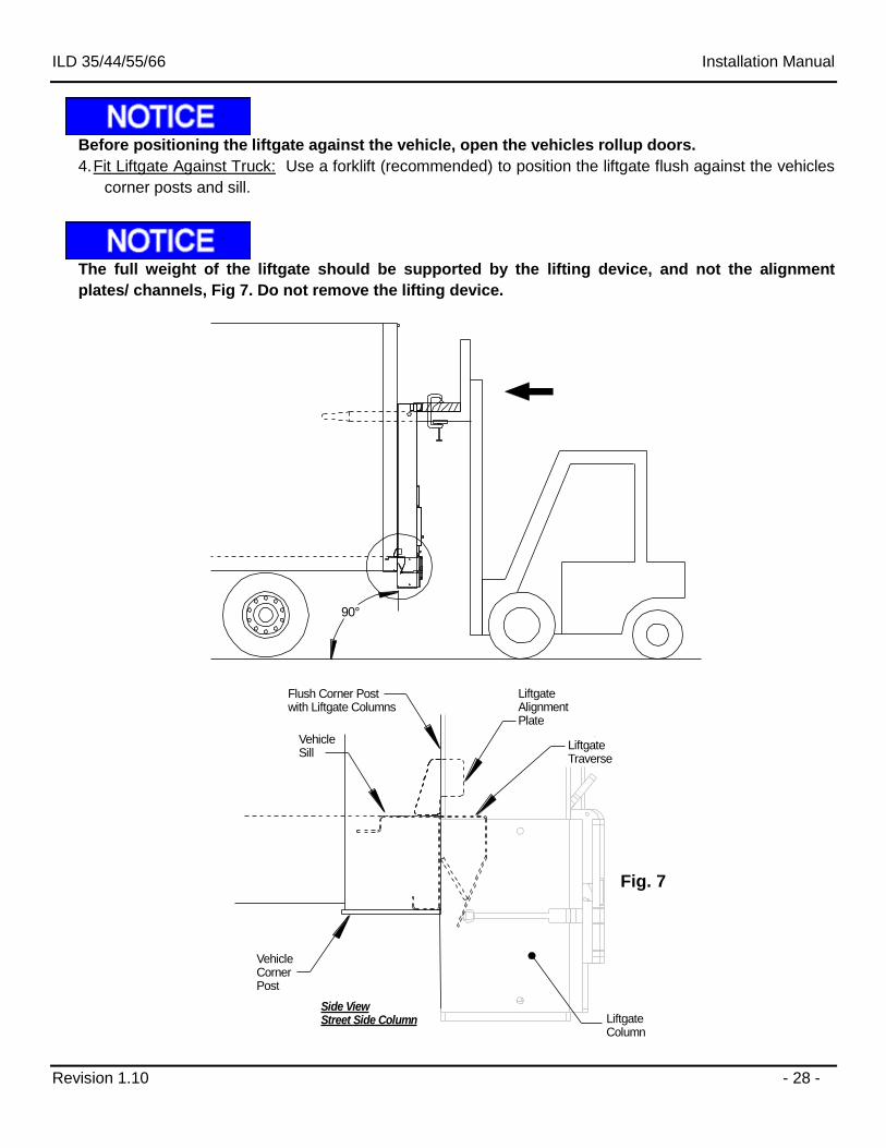
Before positioning the liftgate against the vehicle, open the vehicles rollup doors.
4. Fit Liftgate Against Truck: Use a forklift (recommended) to position the liftgate flush against the vehicles
corner posts and sill.
The full weight of the liftgate should be supported by the lifting device, and not the alignment
plates/ channels, Fig 7. Do not remove the lifting device.
LiftgateAlignment Plate
VehicleSill
Liftgate Traverse
VehicleCornerPost
LiftgateColumn
Flush Corner Post with Liftgate Columns
Side ViewStreet Side Column
90°
Fig. 7
ILD 35/44/55/66 Installation Manual
Revision 1.10 - 29 -
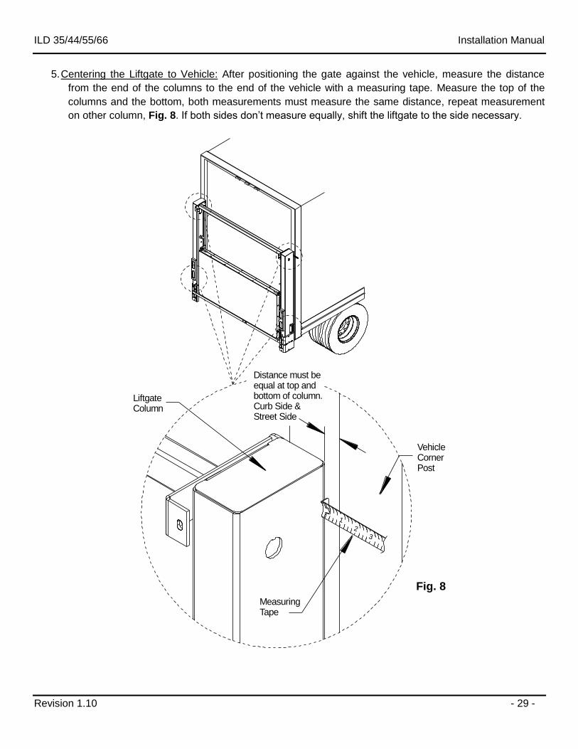
5. Centering the Liftgate to Vehicle: After positioning the gate against the vehicle, measure the distance
from the end of the columns to the end of the vehicle with a measuring tape. Measure the top of the
columns and the bottom, both measurements must measure the same distance, repeat measurement
on other column, Fig. 8. If both sides don’t measure equally, shift the liftgate to the side necessary.
1
23
LiftgateColumn
VehicleCornerPost
MeasuringTape
Distance must be equal at top andbottom of column.Curb Side &Street Side
Fig. 8
ILD 35/44/55/66 Installation Manual
Revision 1.10 - 30 -
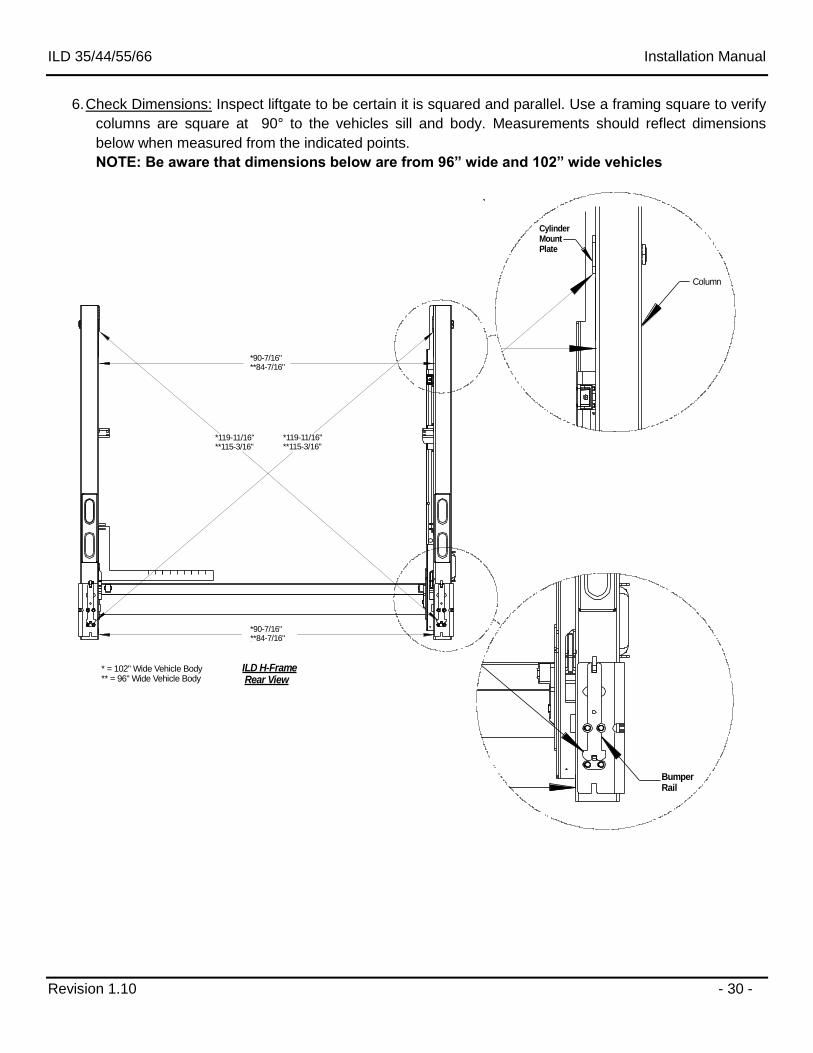
6. Check Dimensions: Inspect liftgate to be certain it is squared and parallel. Use a framing square to verify
columns are square at 90° to the vehicles sill and body. Measurements should reflect dimensions
below when measured from the indicated points.
NOTE: Be aware that dimensions below are from 96” wide and 102” wide vehicles
Column
CylinderMountPlate
ILD H-Frame Rear View
*119-11/16"**115-3/16"
* = 102" Wide Vehicle Body** = 96" Wide Vehicle Body
*119-11/16"**115-3/16"
*90-7/16"**84-7/16"
*90-7/16"**84-7/16"
Bumper Rail
ILD 35/44/55/66 Installation Manual
Revision 1.10 - 31 -
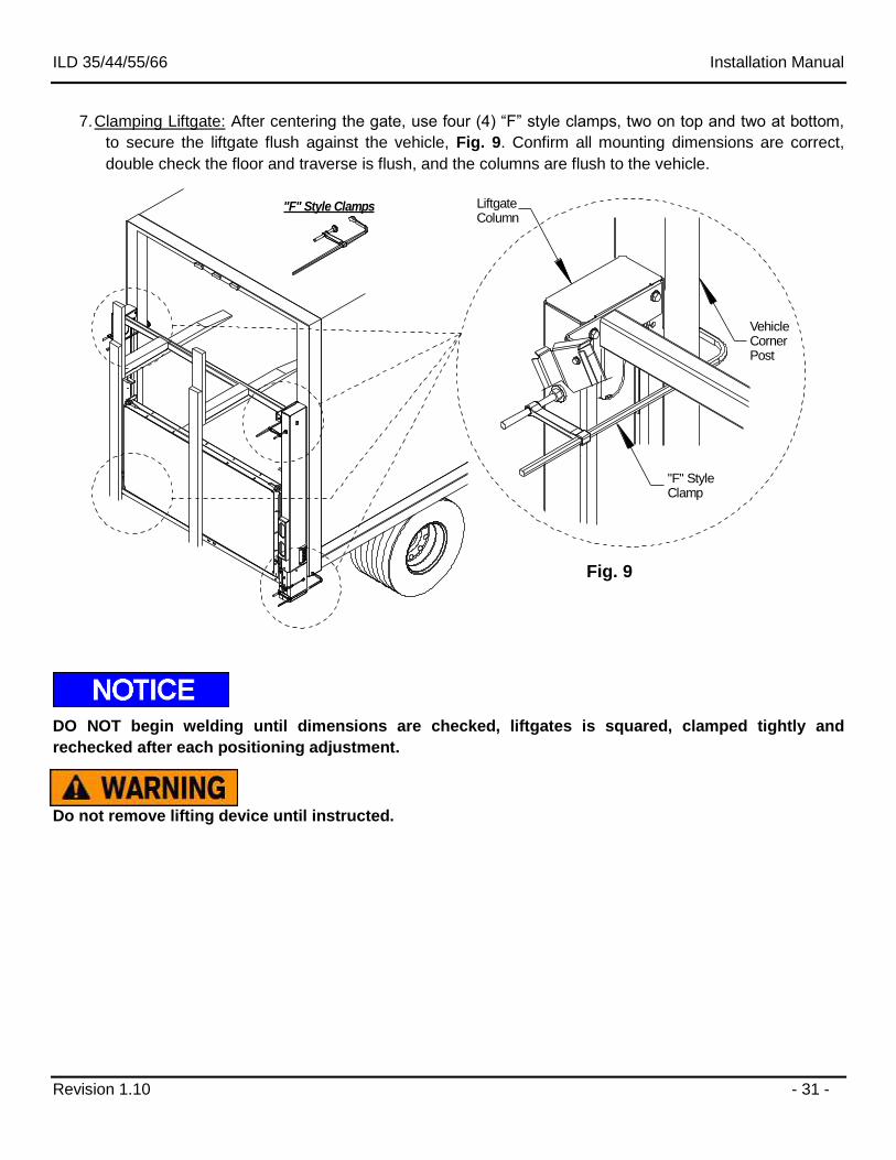
7. Clamping Liftgate: After centering the gate, use four (4) “F” style clamps, two on top and two at bottom,
to secure the liftgate flush against the vehicle, Fig. 9. Confirm all mounting dimensions are correct,
double check the floor and traverse is flush, and the columns are flush to the vehicle.
LiftgateColumn
VehicleCornerPost
"F" StyleClamp
"F" Style Clamps
DO NOT begin welding until dimensions are checked, liftgates is squared, clamped tightly and
rechecked after each positioning adjustment.
Do not remove lifting device until instructed.
Fig. 9
ILD 35/44/55/66 Installation Manual
Revision 1.10 - 32 -
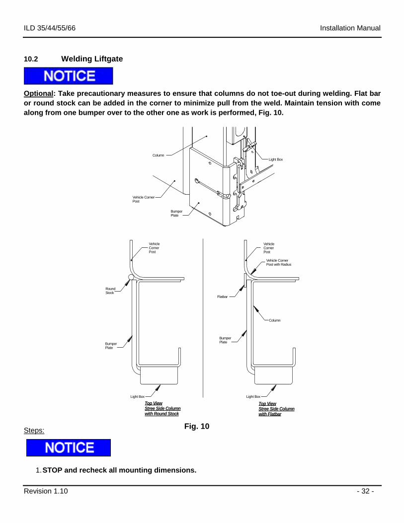
10.2 Welding Liftgate
Optional: Take precautionary measures to ensure that columns do not toe-out during welding. Flat bar
or round stock can be added in the corner to minimize pull from the weld. Maintain tension with come
along from one bumper over to the other one as work is performed, Fig. 10.
VehicleCornerPost
Flatbar
VehicleCornerPost
Vehicle CornerPost with Radius
BumperPlate
BumperPlate
Vehicle CornerPost
Light Box
Light Box
Top ViewStree Side Columnwith Flatbar
Top ViewStree Side Columnwith Round Stock
RoundStock
BumperPlate
Light Box
Column
Column
Steps:
1. STOP and recheck all mounting dimensions.
Fig. 10
ILD 35/44/55/66 Installation Manual
Revision 1.10 - 33 -
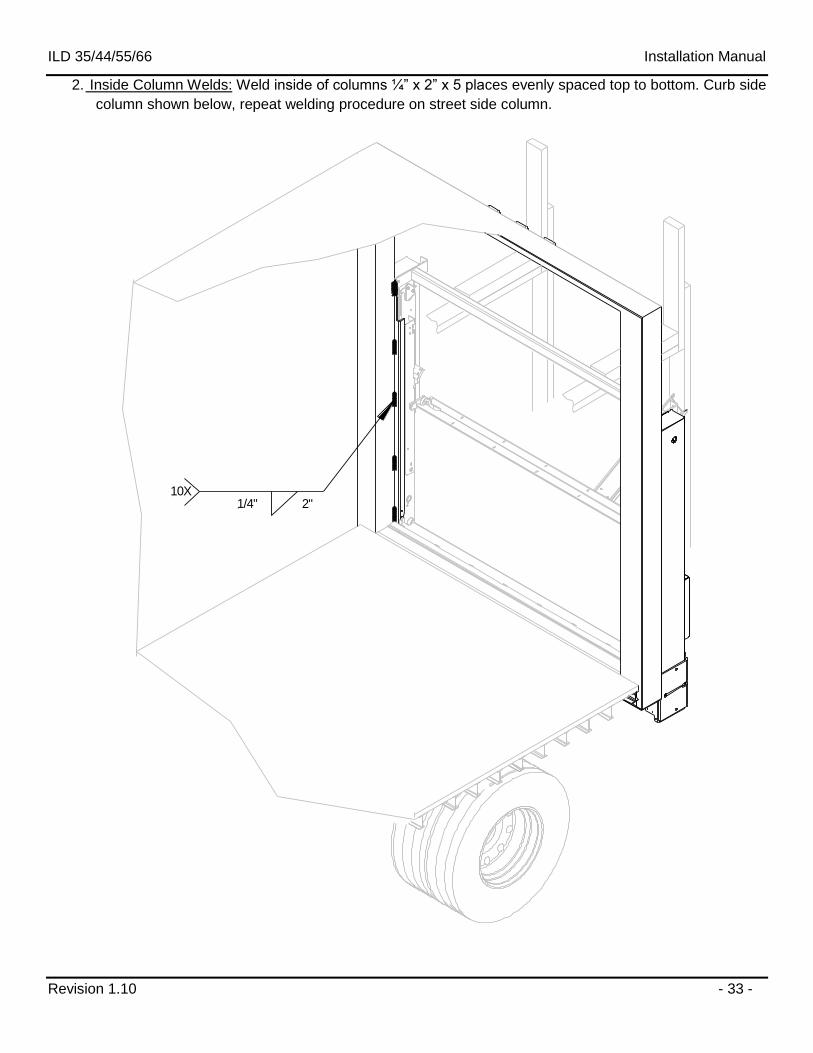
2. Inside Column Welds: Weld inside of columns ¼” x 2” x 5 places evenly spaced top to bottom. Curb side
column shown below, repeat welding procedure on street side column.
1/4" 2"10X
ILD 35/44/55/66 Installation Manual
Revision 1.10 - 34 -
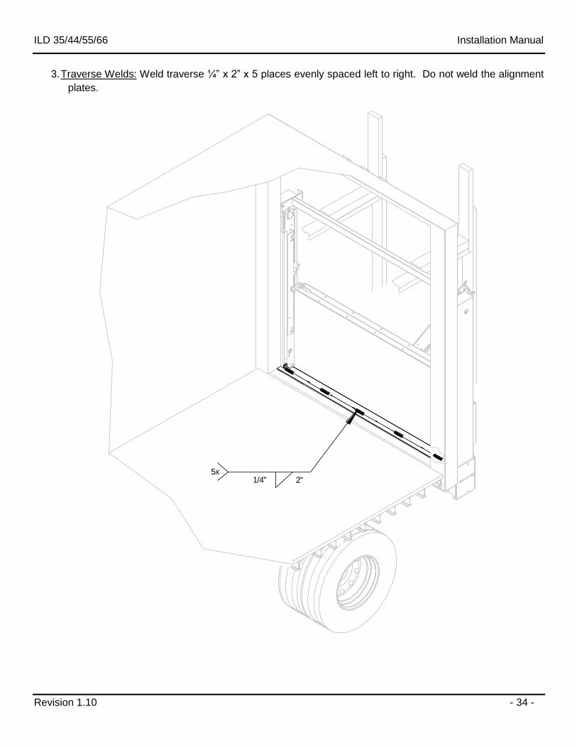
3. Traverse Welds: Weld traverse ¼” x 2” x 5 places evenly spaced left to right. Do not weld the alignment
plates.
1/4" 2"5x
ILD 35/44/55/66 Installation Manual
Revision 1.10 - 35 -
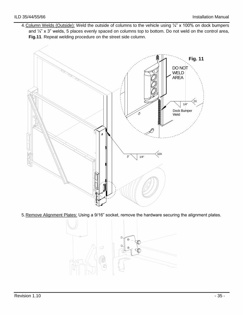
4. Column Welds (Outside): Weld the outside of columns to the vehicle using ¼” x 100% on dock bumpers
and ¼” x 3” welds, 5 places evenly spaced on columns top to bottom. Do not weld on the control area,
Fig.11. Repeat welding procedure on the street side column.
2X
DO NOTWELDAREA
1/4"3"10X
1/4"
Dock BumperWeld
5. Remove Alignment Plates: Using a 9/16” socket, remove the hardware securing the alignment plates.
Fig. 11
ILD 35/44/55/66 Installation Manual
Revision 1.10 - 36 -
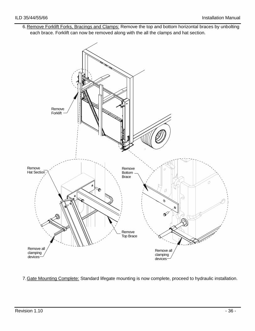
6. Remove Forklift Forks, Bracings and Clamps: Remove the top and bottom horizontal braces by unbolting
each brace. Forklift can now be removed along with the all the clamps and hat section.
RemoveTop Brace
Remove allclamping devices
RemoveBottomBrace
Remove allclamping devices
RemoveForklift
RemoveHat Section
7. Gate Mounting Complete: Standard lifegate mounting is now complete, proceed to hydraulic installation.
ILD 35/44/55/66 Installation Manual
Revision 1.10 - 37 -
11 Hydraulic Installation
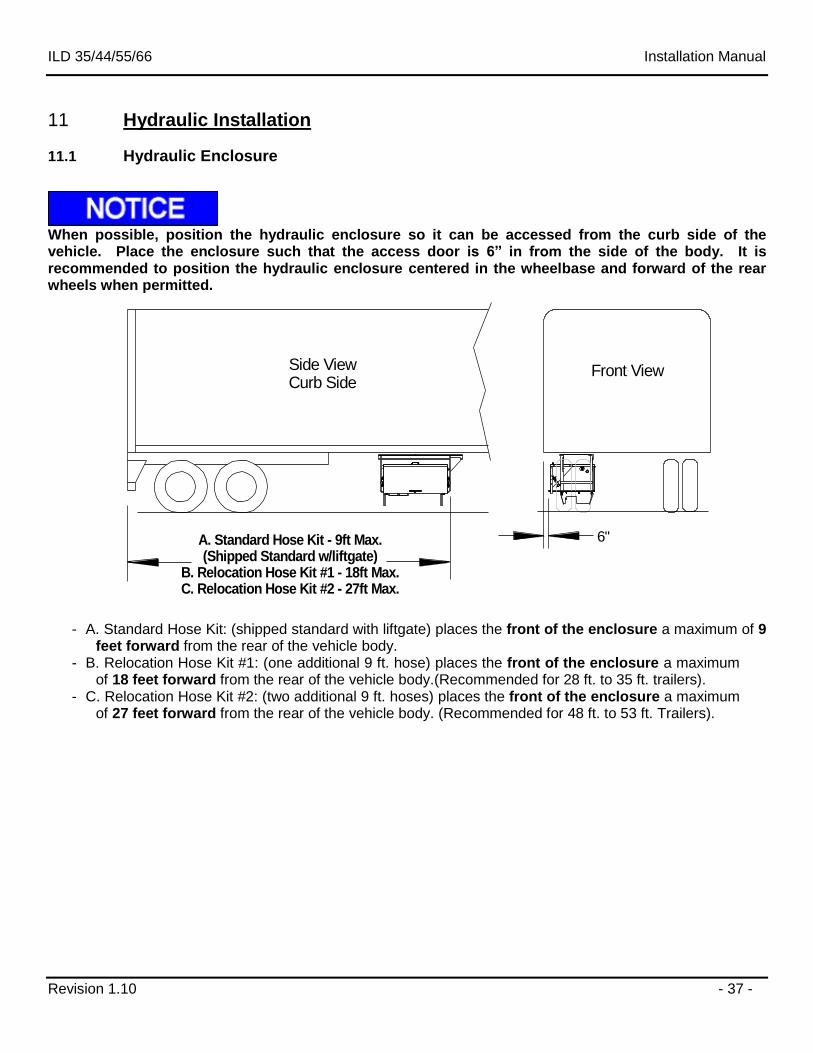
11.1 Hydraulic Enclosure
When possible, position the hydraulic enclosure so it can be accessed from the curb side of the vehicle. Place the enclosure such that the access door is 6” in from the side of the body. It is recommended to position the hydraulic enclosure centered in the wheelbase and forward of the rear wheels when permitted.
A. Standard Hose Kit - 9ft Max.(Shipped Standard w/liftgate)
B. Relocation Hose Kit #1 - 18ft Max.C. Relocation Hose Kit #2 - 27ft Max.
Side ViewCurb Side
Front View
6"
- A. Standard Hose Kit: (shipped standard with liftgate) places the front of the enclosure a maximum of 9 feet forward from the rear of the vehicle body.
- B. Relocation Hose Kit #1: (one additional 9 ft. hose) places the front of the enclosure a maximum of 18 feet forward from the rear of the vehicle body.(Recommended for 28 ft. to 35 ft. trailers).
- C. Relocation Hose Kit #2: (two additional 9 ft. hoses) places the front of the enclosure a maximum of 27 feet forward from the rear of the vehicle body. (Recommended for 48 ft. to 53 ft. Trailers).
ILD 35/44/55/66 Installation Manual
Revision 1.10 - 38 -
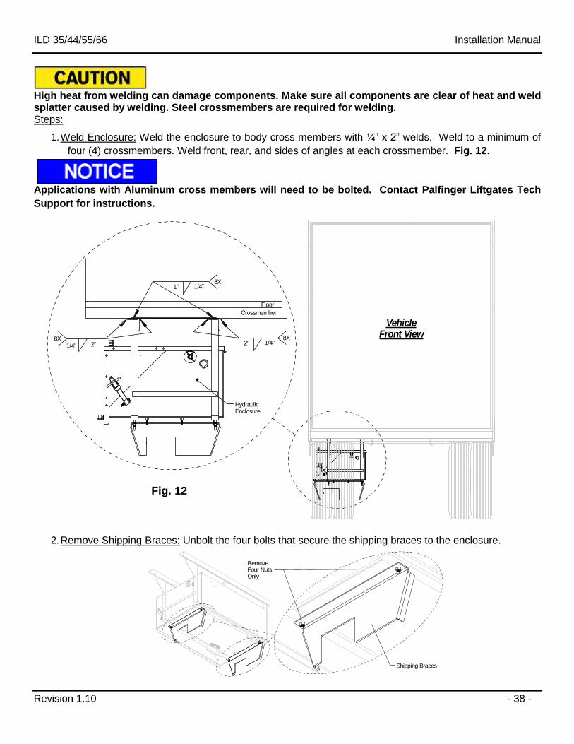
High heat from welding can damage components. Make sure all components are clear of heat and weld splatter caused by welding. Steel crossmembers are required for welding. Steps:
1. Weld Enclosure: Weld the enclosure to body cross members with ¼” x 2” welds. Weld to a minimum of
four (4) crossmembers. Weld front, rear, and sides of angles at each crossmember. Fig. 12.
Applications with Aluminum cross members will need to be bolted. Contact Palfinger Liftgates Tech
Support for instructions.
VehicleFront View
Crossmember
Floor
1/4" 2"8X 8X
1/4"2"
Hydraulic Enclosure
8X1/4"1"
2. Remove Shipping Braces: Unbolt the four bolts that secure the shipping braces to the enclosure.
Remove Four NutsOnly
Shipping Braces
Fig. 12
ILD 35/44/55/66 Installation Manual
Revision 1.10 - 39 -
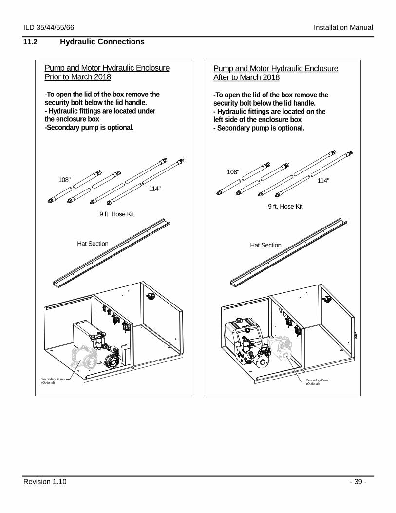
11.2 Hydraulic Connections
9 ft. Hose Kit
108"
114"
Hat Section
9 ft. Hose Kit
108"
114"
Pump and Motor Hydraulic EnclosureAfter to March 2018
-To open the lid of the box remove the security bolt below the lid handle.- Hydraulic fittings are located on theleft side of the enclosure box- Secondary pump is optional.
Pump and Motor Hydraulic EnclosurePrior to March 2018
-To open the lid of the box remove the security bolt below the lid handle.- Hydraulic fittings are located underthe enclosure box-Secondary pump is optional.
Hat Section
Secondary Pump(Optional)
Secondary Pump(Optional)
ILD 35/44/55/66 Installation Manual
Revision 1.10 - 40 -
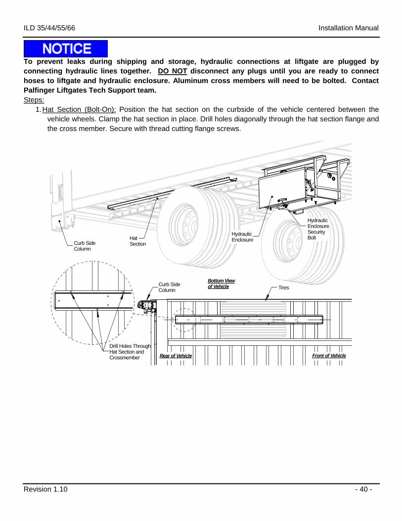
To prevent leaks during shipping and storage, hydraulic connections at liftgate are plugged by
connecting hydraulic lines together. DO NOT disconnect any plugs until you are ready to connect
hoses to liftgate and hydraulic enclosure. Aluminum cross members will need to be bolted. Contact
Palfinger Liftgates Tech Support team.
Steps:
1. Hat Section (Bolt-On): Position the hat section on the curbside of the vehicle centered between the
vehicle wheels. Clamp the hat section in place. Drill holes diagonally through the hat section flange and
the cross member. Secure with thread cutting flange screws.
HydraulicEnclosureSecurity Bolt
Bottom Viewof Vehicle
Curb Side Column
HatSection
HydraulicEnclosure
Drill Holes ThroughHat Section and Crossmember Front of VehicleRear of Vehicle
Curb Side Column
Tires
ILD 35/44/55/66 Installation Manual
Revision 1.10 - 41 -
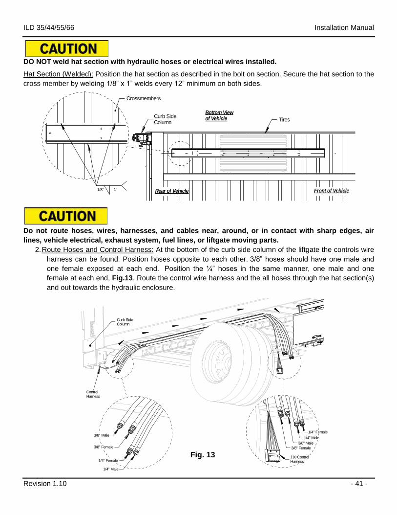
DO NOT weld hat section with hydraulic hoses or electrical wires installed.
Hat Section (Welded): Position the hat section as described in the bolt on section. Secure the hat section to the
cross member by welding 1/8” x 1” welds every 12” minimum on both sides.
Bottom Viewof Vehicle
Front of VehicleRear of Vehicle
Curb Side Column
Tires
1/8" 1"
Crossmembers
Do not route hoses, wires, harnesses, and cables near, around, or in contact with sharp edges, air
lines, vehicle electrical, exhaust system, fuel lines, or liftgate moving parts.
2. Route Hoses and Control Harness: At the bottom of the curb side column of the liftgate the controls wire
harness can be found. Position hoses opposite to each other. 3/8” hoses should have one male and
one female exposed at each end. Position the ¼” hoses in the same manner, one male and one
female at each end, Fig.13. Route the control wire harness and the all hoses through the hat section(s)
and out towards the hydraulic enclosure.
3/8" Male
3/8" Female
1/4" Female
1/4" Male
3/8" Male
3/8" Female
1/4" Female
1/4" Male
J30 ControlHarness
Curb SideColumn
Control Harness
Fig. 13
ILD 35/44/55/66 Installation Manual
Revision 1.10 - 42 -
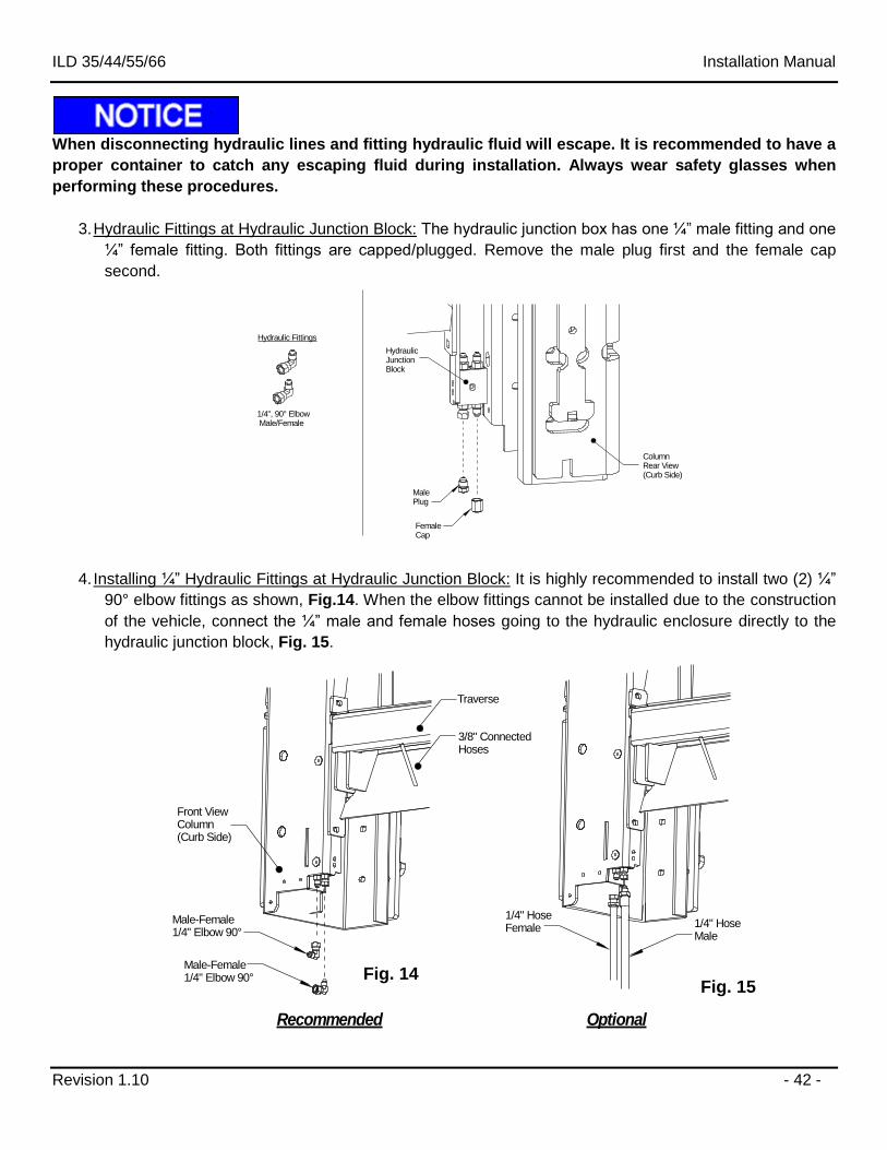
When disconnecting hydraulic lines and fitting hydraulic fluid will escape. It is recommended to have a
proper container to catch any escaping fluid during installation. Always wear safety glasses when
performing these procedures.
3. Hydraulic Fittings at Hydraulic Junction Block: The hydraulic junction box has one ¼” male fitting and one
¼” female fitting. Both fittings are capped/plugged. Remove the male plug first and the female cap
second.
Male Plug
FemaleCap
ColumnRear View(Curb Side)
HydraulicJunctionBlock
1/4", 90° Elbow Male/Female
Hydraulic Fittings
4. Installing ¼” Hydraulic Fittings at Hydraulic Junction Block: It is highly recommended to install two (2) ¼”
90° elbow fittings as shown, Fig.14. When the elbow fittings cannot be installed due to the construction
of the vehicle, connect the ¼” male and female hoses going to the hydraulic enclosure directly to the
hydraulic junction block, Fig. 15.
Front ViewColumn(Curb Side)
Male-Female1/4" Elbow 90°
Male-Female1/4" Elbow 90°
1/4" HoseMale
1/4" HoseFemale
Traverse
Recommended Optional
3/8" ConnectedHoses
Fig. 14 Fig. 15
ILD 35/44/55/66 Installation Manual
Revision 1.10 - 43 -
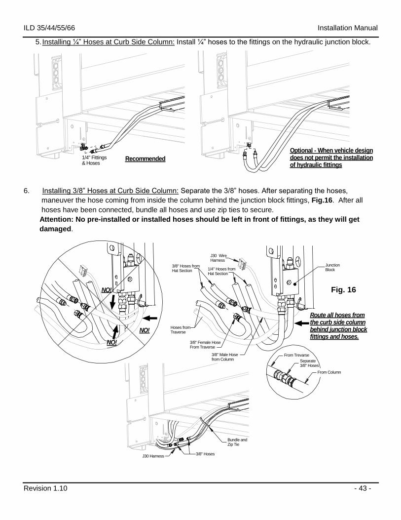
5. Installing ¼” Hoses at Curb Side Column: Install ¼” hoses to the fittings on the hydraulic junction block.
Recommended
Optional - When vehicle designdoes not permit the installationof hydraulic fittings
1/4" Fittings& Hoses
6. Installing 3/8” Hoses at Curb Side Column: Separate the 3/8” hoses. After separating the hoses,
maneuver the hose coming from inside the column behind the junction block fittings, Fig.16. After all
hoses have been connected, bundle all hoses and use zip ties to secure.
Attention: No pre-installed or installed hoses should be left in front of fittings, as they will get
damaged.
NO!
Route all hoses fromthe curb side columnbehind junction blockfittings and hoses.
3/8" Hoses
Junction Block
3/8" Hoses fromHat Section
Bundle and Zip Tie
Hoses from Traverse
1/4" Hoses fromHat Section
Separate3/8" Hoses
3/8" Male Hose from Column
3/8" Female Hose From Traverse
From Trevarse
From Column
NO!
J30 WireHarness
NO!
J30 Harness
Fig. 16
ILD 35/44/55/66 Installation Manual
Revision 1.10 - 44 -
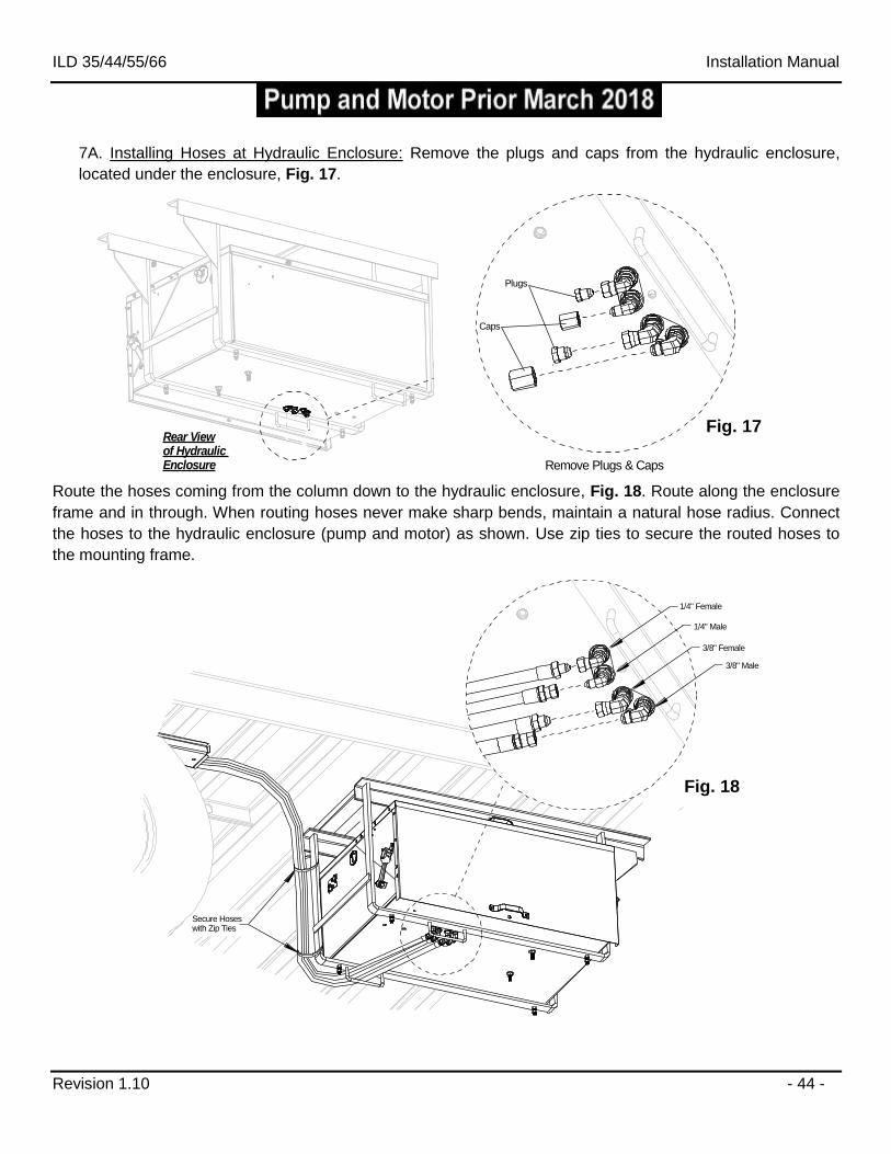
7A. Installing Hoses at Hydraulic Enclosure: Remove the plugs and caps from the hydraulic enclosure,
located under the enclosure, Fig. 17.
Remove Plugs & Caps
Rear Viewof Hydraulic Enclosure
Caps
Plugs
Route the hoses coming from the column down to the hydraulic enclosure, Fig. 18. Route along the enclosure
frame and in through. When routing hoses never make sharp bends, maintain a natural hose radius. Connect
the hoses to the hydraulic enclosure (pump and motor) as shown. Use zip ties to secure the routed hoses to
the mounting frame.
3/8" Female
1/4" Female
1/4" Male
3/8" Male
Secure Hoseswith Zip Ties
Fig. 17
Fig. 18
ILD 35/44/55/66 Installation Manual
Revision 1.10 - 45 -
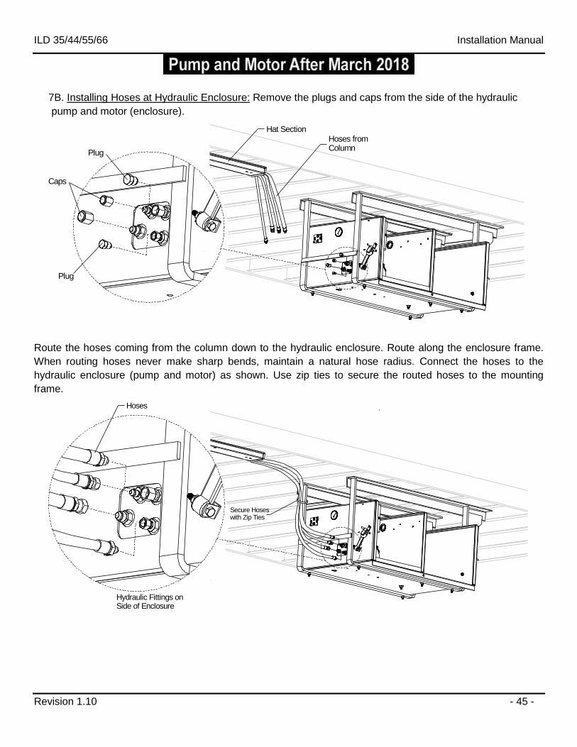
7B. Installing Hoses at Hydraulic Enclosure: Remove the plugs and caps from the side of the hydraulic
pump and motor (enclosure).
Hat SectionHoses from Column
Caps
Plug
Plug
Route the hoses coming from the column down to the hydraulic enclosure. Route along the enclosure frame.
When routing hoses never make sharp bends, maintain a natural hose radius. Connect the hoses to the
hydraulic enclosure (pump and motor) as shown. Use zip ties to secure the routed hoses to the mounting
frame.
Hydraulic Fittings on Side of Enclosure
Hoses
Secure Hoseswith Zip Ties
ILD 35/44/55/66 Installation Manual
Revision 1.10 - 46 -
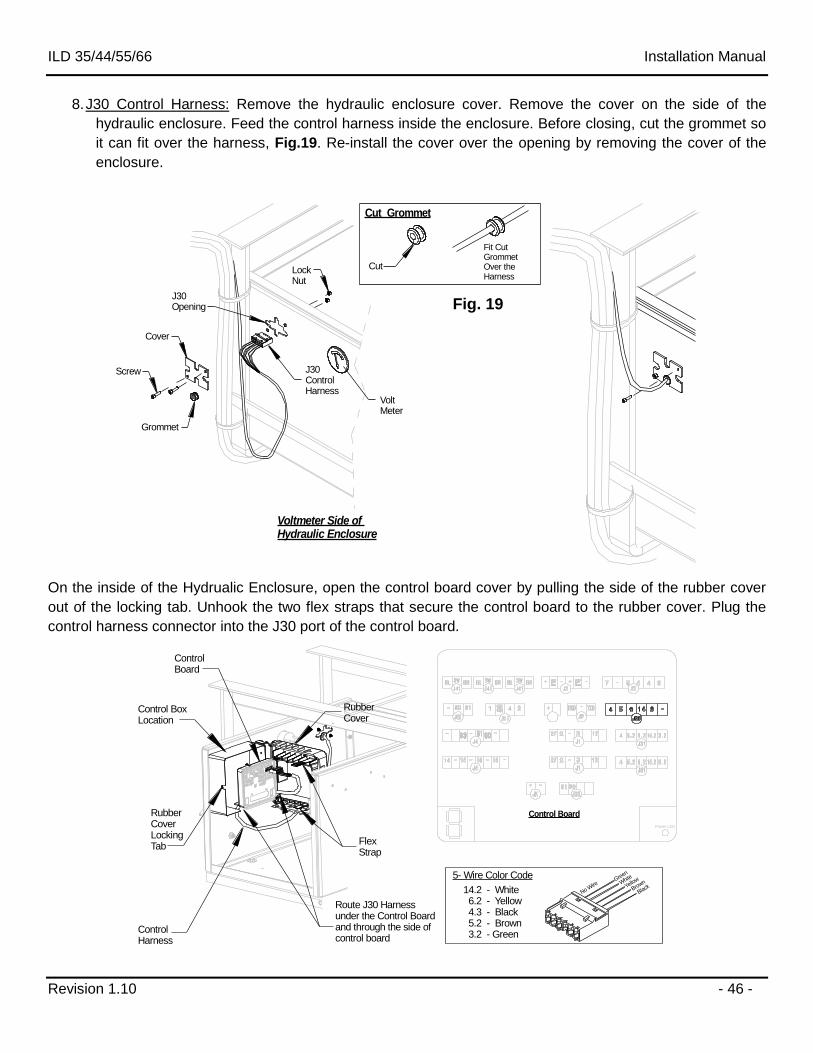
8. J30 Control Harness: Remove the hydraulic enclosure cover. Remove the cover on the side of the
hydraulic enclosure. Feed the control harness inside the enclosure. Before closing, cut the grommet so
it can fit over the harness, Fig.19. Re-install the cover over the opening by removing the cover of the
enclosure.
Cut Grommet
Cut
Fit Cut GrommetOver the Harness
Cover
J30Opening
Grommet
J30 ControlHarness
Voltmeter Side of Hydraulic Enclosure
Screw
LockNut
VoltMeter
On the inside of the Hydrualic Enclosure, open the control board cover by pulling the side of the rubber cover
out of the locking tab. Unhook the two flex straps that secure the control board to the rubber cover. Plug the
control harness connector into the J30 port of the control board.
Power LED
Control BoxLocation
FlexStrap
Rubber CoverLocking Tab
Control Board
ControlBoard
ControlHarness
Rubber Cover
Route J30 Harnessunder the Control Boardand through the side of control board
5- Wire Color Code
14.2 - White 6.2 - Yellow 4.3 - Black 5.2 - Brown 3.2 - Green
Green
White
Yellow
Brown
BlackNo W
ire
Fig. 19
ILD 35/44/55/66 Installation Manual
Revision 1.10 - 47 -
Cab Shutoff Switch Installation (Optional)
Steps:
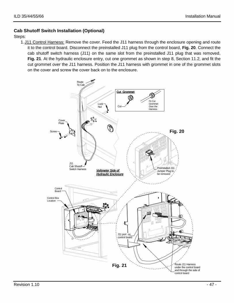
1. J11 Control Harness: Remove the cover. Feed the J11 harness through the enclosure opening and route
it to the control board. Disconnect the preinstalled J11 plug from the control board, Fig. 20. Connect the
cab shutoff switch harness (J11) on the same slot from the preinstalled J11 plug that was removed,
Fig. 21. At the hydraulic enclosure entry, cut one grommet as shown in step 8, Section 11.2, and fit the
cut grommet over the J11 harness. Position the J11 harness with grommet in one of the grommet slots
on the cover and screw the cover back on to the enclosure.
Voltmeter Side of Hydraulic Enclosure
Cut Grommet
Cut
Fit Cut GrommetOver the Harness
CoverPlate
Screw
LockNut
Control BoxLocation
ControlBoard
Route J11 Harnessunder the control boardand through the side of control board
Route To Cab
J11Cab ShutoffSwitch Harness
J11 port oncontrol board
Preinstalled J11 Jumper Plug tobe removed
Fig. 20
Fig. 21
ILD 35/44/55/66 Installation Manual
Revision 1.10 - 48 -
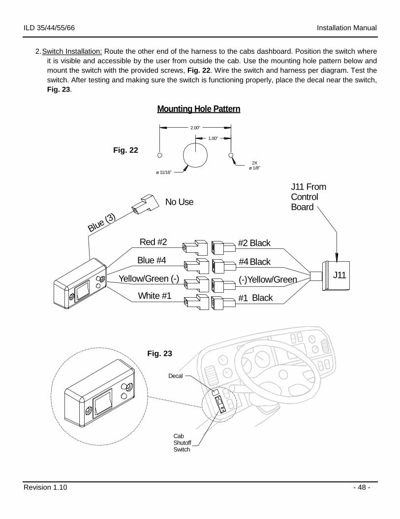
2. Switch Installation: Route the other end of the harness to the cabs dashboard. Position the switch where
it is visible and accessible by the user from outside the cab. Use the mounting hole pattern below and
mount the switch with the provided screws, Fig. 22. Wire the switch and harness per diagram. Test the
switch. After testing and making sure the switch is functioning properly, place the decal near the switch,
Fig. 23.
ø 11/16"
2Xø 1/8"
No Use
Blue #4
Black
Black
(-)Yellow/GreenYellow/Green (-)
#2
#4
#1
Red #2
J11
Black
Blue (3)
White #1
J11 From ControlBoard
Decal
Cab ShutoffSwitch
Mounting Hole Pattern
1.00"
2.00"
Fig. 22
Fig. 23
ILD 35/44/55/66 Installation Manual
Revision 1.10 - 49 -
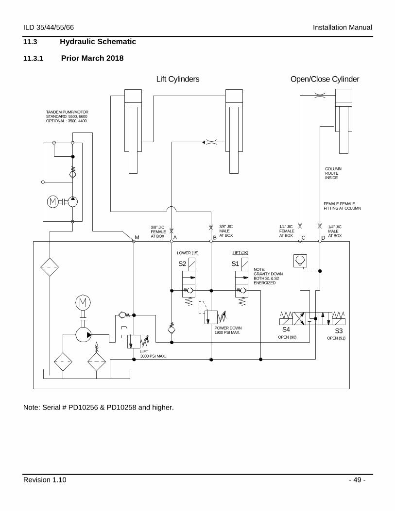
11.3 Hydraulic Schematic
11.3.1 Prior March 2018
Lift Cylinders Open/Close Cylinder
S2 S1
S4
A B DM C
S3
NOTE:GRAVITY DOWNBOTH S1 & S2ENERGIZED
OPEN (90) OPEN (91)
POWER DOWN1900 PSI MAX.
LIFT 3000 PSI MAX.
TANDEM PUMP/MOTORSTANDARD: 5500, 6600OPTIONAL : 3500, 4400
COLUMNROUTE INSIDE
FEMALE-FEMALEFITTING AT COLUMN
3/8" JIC MALEAT BOX
3/8" JIC FEMALEAT BOX
1/4" JIC FEMALEAT BOX
1/4" JIC MALEAT BOX
LOWER (15) LIFT (JK)
Note: Serial # PD10256 & PD10258 and higher.
ILD 35/44/55/66 Installation Manual
Revision 1.10 - 50 -
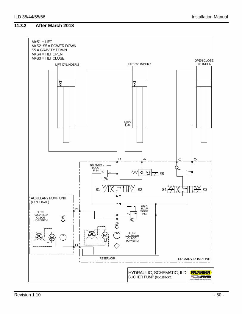
11.3.2 After March 2018
HYDRAULIC, SCHEMATIC, ILD BUCHER PUMP (90-1118-001)
15939 Piuma Ave. Cerritos, CA 90703
M
207 BAR3000 PSI
AB
69 BAR1000 PSI
C D
1.72 CC/REV0.105
IN³/REV
T1
P1
M
1.72 CC/REV0.105
IN³/REV
S1 S2
S5
S4 S3
M+S1 = LIFTM+S2+S5 = POWER DOWNS5 = GRAVITY DOWNM+S4 = TILT OPENM+S3 = TILT CLOSE
LIFT CYLINDER 1LIFT CYLINDER 2
OPEN CLOSECYLINDER
AUXILLARY PUMP UNIT(OPTIONAL)
PRIMARY PUMP UNITRESERVOIR
2.6 GPM
ILD 35/44/55/66 Installation Manual
Revision 1.10 - 51 -
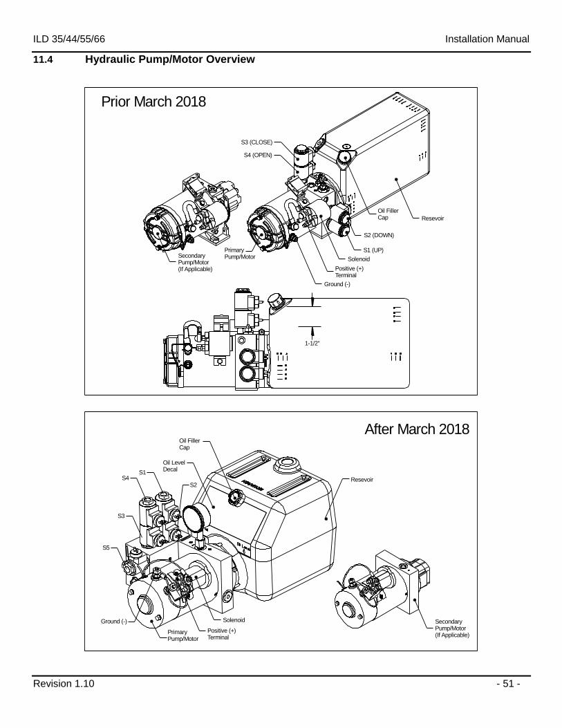
11.4 Hydraulic Pump/Motor Overview
1-1/2"
Resevoir
Oil FillerCap
Solenoid
S2 (DOWN)
S1 (UP)
S3 (CLOSE)
S4 (OPEN)
Primary Pump/MotorSecondary
Pump/Motor(If Applicable) Positive (+)
Terminal
Ground (-)
Prior March 2018
After March 2018
Ground (-)
Positive (+)Terminal
Solenoid
Oil FillerCap
Resevoir
SecondaryPump/Motor(If Applicable)
Primary Pump/Motor
Oil LevelDecal
S5
S3
S4S1
S2
ILD 35/44/55/66 Installation Manual
Revision 1.10 - 52 -
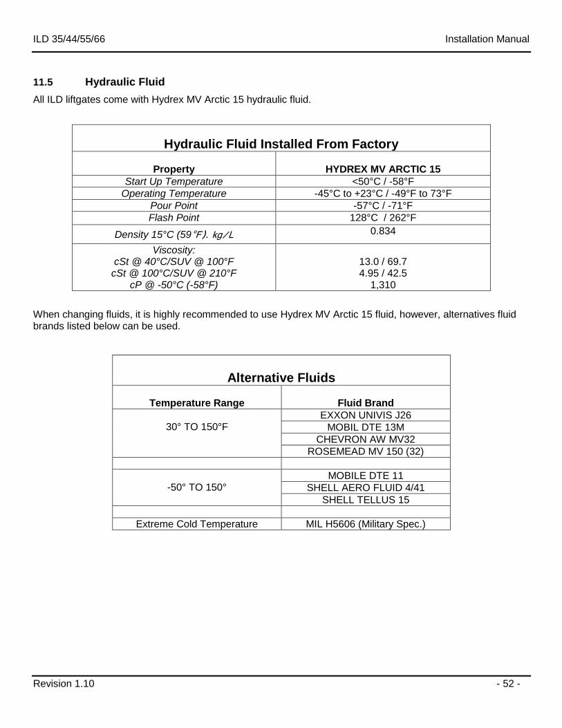
11.5 Hydraulic Fluid
All ILD liftgates come with Hydrex MV Arctic 15 hydraulic fluid.
Hydraulic Fluid Installed From Factory
Property
HYDREX MV ARCTIC 15
Start Up Temperature <50°C / -58°F
Operating Temperature -45°C to +23°C / -49°F to 73°F
Pour Point -57°C / -71°F
Flash Point 128°C / 262°F
Density 15°C (59°F). kg/L 0.834
Viscosity: cSt @ 40°C/SUV @ 100°F
cSt @ 100°C/SUV @ 210°F cP @ -50°C (-58°F)
13.0 / 69.7 4.95 / 42.5
1,310
When changing fluids, it is highly recommended to use Hydrex MV Arctic 15 fluid, however, alternatives fluid brands listed below can be used.
Alternative Fluids
Temperature Range
Fluid Brand
30° TO 150°F
EXXON UNIVIS J26
MOBIL DTE 13M
CHEVRON AW MV32
ROSEMEAD MV 150 (32)
-50° TO 150°
MOBILE DTE 11
SHELL AERO FLUID 4/41
SHELL TELLUS 15
Extreme Cold Temperature MIL H5606 (Military Spec.)
ILD 35/44/55/66 Installation Manual
Revision 1.10 - 53 -
12 Electrical Installation
When performing electrical installation, please be certain to install and secure everything in a way where it is not subject to damage from moving parts, sharp edges, exhaust systems, fuel lines, etc. It is recommended to use dielectric grease on all electrical connections.
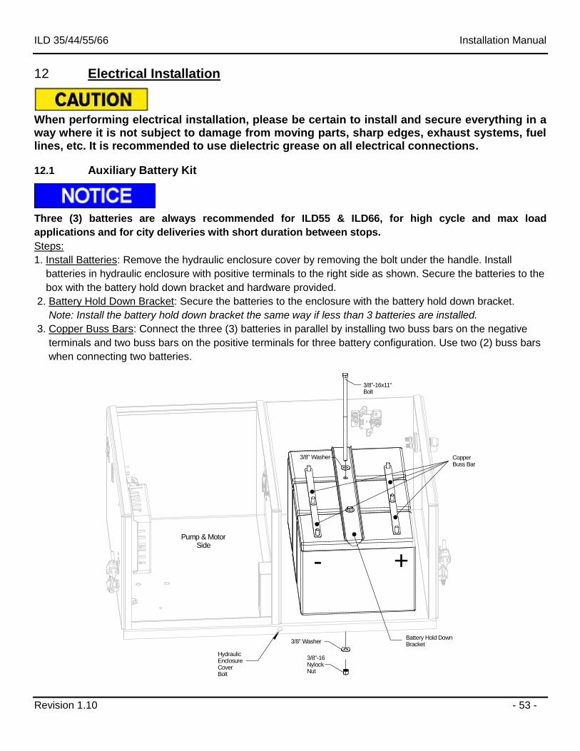
12.1 Auxiliary Battery Kit
Three (3) batteries are always recommended for ILD55 & ILD66, for high cycle and max load
applications and for city deliveries with short duration between stops.
Steps:
1. Install Batteries: Remove the hydraulic enclosure cover by removing the bolt under the handle. Install
batteries in hydraulic enclosure with positive terminals to the right side as shown. Secure the batteries to the
box with the battery hold down bracket and hardware provided.
2. Battery Hold Down Bracket: Secure the batteries to the enclosure with the battery hold down bracket.
Note: Install the battery hold down bracket the same way if less than 3 batteries are installed.
3. Copper Buss Bars: Connect the three (3) batteries in parallel by installing two buss bars on the negative
terminals and two buss bars on the positive terminals for three battery configuration. Use two (2) buss bars
when connecting two batteries.
+-
3/8"-16x11"Bolt
3/8" Washer
3/8" Washer
3/8"-16 NylockNut
CopperBuss Bar
Battery Hold DownBracket
HydraulicEnclosureCoverBolt
Pump & Motor Side
ILD 35/44/55/66 Installation Manual
Revision 1.10 - 54 -
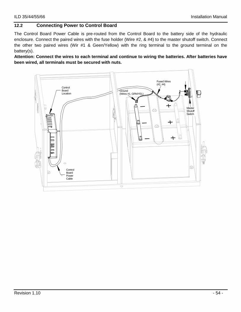
12.2 Connecting Power to Control Board
The Control Board Power Cable is pre-routed from the Control Board to the battery side of the hydraulic
enclosure. Connect the paired wires with the fuse holder (Wire #2, & #4) to the master shutoff switch. Connect
the other two paired wires (Wir #1 & Geen/Yellow) with the ring terminal to the ground terminal on the
battery(s).
Attention: Connect the wires to each terminal and continue to wiring the batteries. After batteries have
been wired, all terminals must be secured with nuts.
Ground(Wires #1, GRN/YEL)
MasterShutoffSwitch
ControlBoardPowerCable
ControlBoardLocation
Fused Wires (#2, #4)
ILD 35/44/55/66 Installation Manual
Revision 1.10 - 55 -
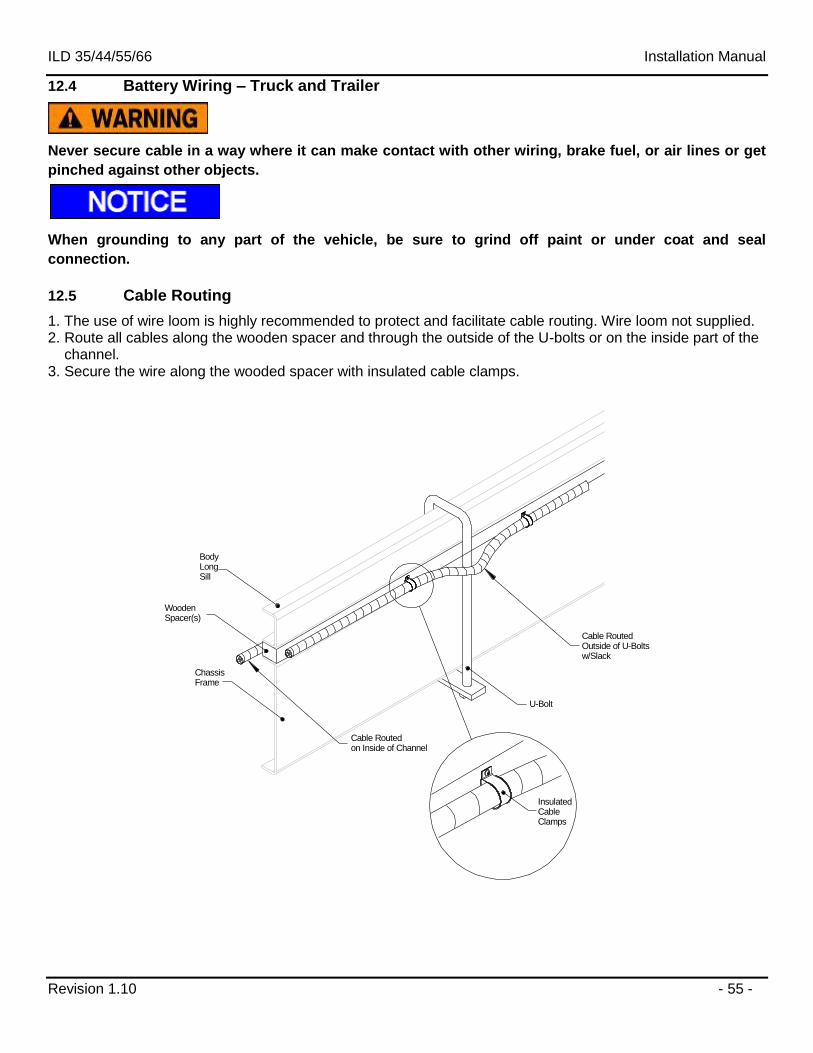
12.4 Battery Wiring – Truck and Trailer
Never secure cable in a way where it can make contact with other wiring, brake fuel, or air lines or get
pinched against other objects.
When grounding to any part of the vehicle, be sure to grind off paint or under coat and seal
connection.
12.5 Cable Routing
1. The use of wire loom is highly recommended to protect and facilitate cable routing. Wire loom not supplied. 2. Route all cables along the wooden spacer and through the outside of the U-bolts or on the inside part of the channel. 3. Secure the wire along the wooded spacer with insulated cable clamps.
Body Long Sill
Wooden Spacer(s)
Chassis Frame
U-Bolt
Cable RoutedOutside of U-Boltsw/Slack
InsulatedCableClamps
Cable Routedon Inside of Channel
ILD 35/44/55/66 Installation Manual
Revision 1.10 - 56 -
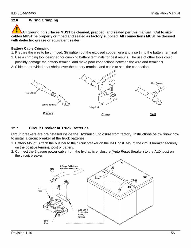
12.6 Wiring Crimping
All grounding surfaces MUST be cleaned, prepped, and sealed per this manual. “Cut to size” cables MUST be properly crimped and sealed as factory supplied. All connections MUST be dressed
with dielectric grease or equivalent sealer. Battery Cable Crimping 1. Prepare the wire to be crimped. Straighten out the exposed copper wire and insert into the battery terminal.
2. Use a crimping tool designed for crimping battery terminals for best results. The use of other tools could
possibly damage the battery terminal and make poor connections between the wire and terminals.
3. Slide the provided heat shrink over the battery terminal and cable to seal the connection.
Prepare Crimp Seal
Heat Shrink
Battery Terminal
Crimp Tool
Heat Source
12.7 Circuit Breaker at Truck Batteries
Circuit breakers are preinstalled inside the Hydraulic Enclosure from factory. Instructions below show how to install a circuit breaker at the truck batteries.
1. Battery Mount: Attach the bus bar to the circuit breaker on the BAT post. Mount the circuit breaker securely
on the positive terminal post of battery.
2. Connect the 2 gauge power cable from the hydraulic enclosure (Auto Reset Breaker) to the AUX post on the circuit breaker.
Buss Bar To Positive (+) BatteryTerminal
2 Gauge Cable from Hydraulic Enclosure
BAT Post
AUXPost
ILD 35/44/55/66 Installation Manual
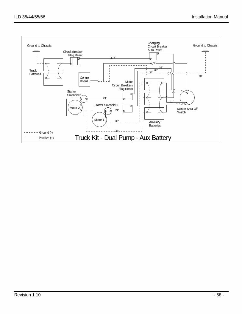
Revision 1.10 - 57 -
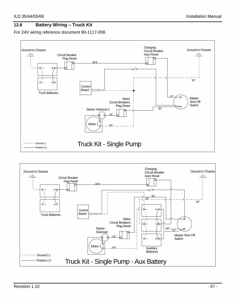
12.8 Battery Wiring – Truck Kit
For 24V wiring reference document 90-1117-008.
50"
ChargingCircuit BreakerAuto Reset
Starter Solenoid 1
Motor 1
Master Shut OffSwitch
Ground to ChassisGround to Chassis
Truck Batteries
Truck Kit - Single Pump
24"
50"
36"
11"
40 ft
MotorCircuit Breakers
Flag Reset
Circuit BreakerFlag Reset
Positive (+)
Ground (-)
Control Board
ChargingCircuit BreakerAuto Reset
Starter Solenoid
Motor 1AuxiliaryBatteries
Master Shut OffSwitch
Ground to ChassisGround to Chassis
Truck Batteries
Truck Kit - Single Pump - Aux Battery
MotorCircuit Breakers
Flag Reset
40 ft
24"
50"
36"
11"
50"
11"
36"
Circuit BreakerFlag Reset
Positive (+)
Ground (-)
Control Board
ILD 35/44/55/66 Installation Manual
Revision 1.10 - 58 -
ChargingCircuit BreakerAuto Reset
Starter Solenoid 2
Starter Solenoid 1Motor 2
Motor 1AuxiliaryBatteries
Master Shut OffSwitch
MotorCircuit Breakers
Flag Reset
Ground to ChassisGround to Chassis
Truck Batteries
Truck Kit - Dual Pump - Aux Battery
40 ft
24"
36"
36"
11"
50"
11"
36"
24"
36"
36"
Circuit BreakerFlag Reset
Positive (+)
Ground (-)
Control Board
ILD 35/44/55/66 Installation Manual
Revision 1.10 - 59 -
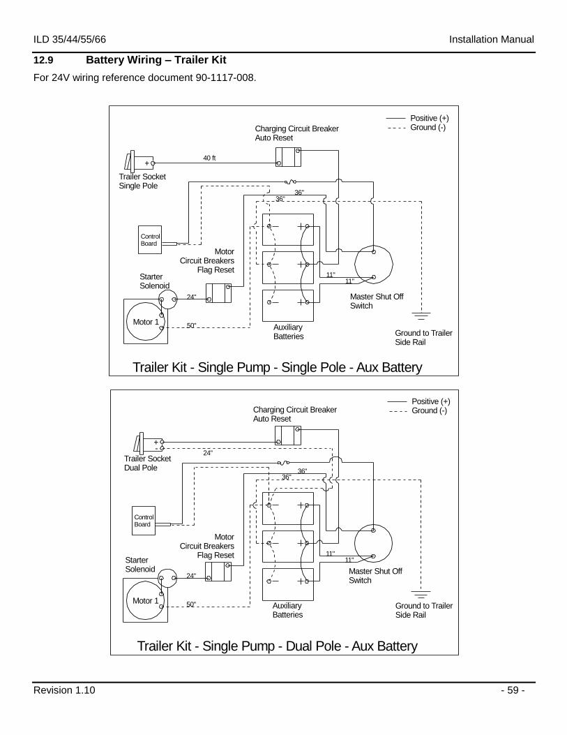
12.9 Battery Wiring – Trailer Kit
For 24V wiring reference document 90-1117-008.
Charging Circuit BreakerAuto Reset
Starter Solenoid
Motor 1
Ground to TrailerSide Rail
Master Shut OffSwitch
Trailer Kit - Single Pump - Single Pole - Aux Battery
MotorCircuit Breakers
Flag Reset
40 ft
24"
50"
36"
11"11"
36"
Charging Circuit BreakerAuto Reset
Starter Solenoid
Motor 1Auxiliary Batteries
Ground to TrailerSide Rail
Master Shut OffSwitch
Trailer Kit - Single Pump - Dual Pole - Aux Battery
MotorCircuit Breakers
Flag Reset
24"
50"
36"
11"11"
36"
24"
Trailer SocketSingle Pole
Trailer SocketDual Pole
Positive (+)Ground (-)
Positive (+)Ground (-)
+-
+
Auxiliary Batteries
Control Board
Control Board
ILD 35/44/55/66 Installation Manual
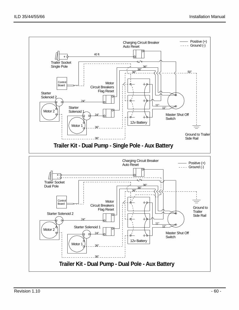
Revision 1.10 - 60 -
Charging Circuit BreakerAuto Reset
Starter Solenoid 2
Starter Solenoid 1Motor 2
Motor 112v Battery
Ground to TrailerSide Rail
Master Shut OffSwitch
Trailer Kit - Dual Pump - Single Pole - Aux Battery
Trailer SocketSingle Pole
MotorCircuit Breakers
Flag Reset
40 ft
24"
36"
36"
11"
50"
11"
36"
24"
36"
36"
Positive (+)Ground (-)
Charging Circuit BreakerAuto Reset
Starter Solenoid 2
Starter Solenoid 1Motor 2
Motor 112v Battery
Ground to TrailerSide Rail
Master Shut OffSwitch
Trailer Kit - Dual Pump - Dual Pole - Aux Battery
Trailer SocketDual Pole
MotorCircuit Breakers
Flag Reset
24"
36"
36"
11"11"
36"
24"
36"
36"
Positive (+)Ground (-)
+
+-
Control Board
Control Board
ILD 35/44/55/66 Installation Manual
Revision 1.10 - 61 -
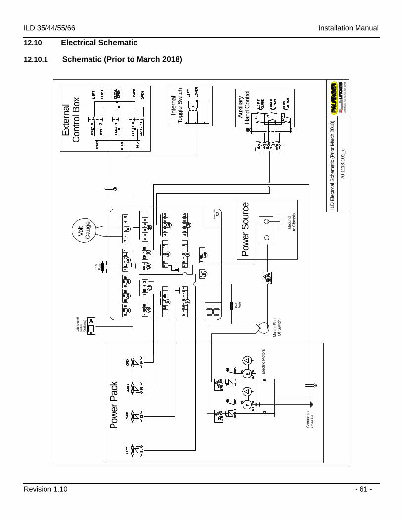
12.10 Electrical Schematic
12.10.1 Schematic (Prior to March 2018)
V
olt
Gauge
Pow
er
LE
D
15939 P
ium
a A
ve. C
err
itos,
CA
90703
70-1
113-1
01_c
ILD
Ele
ctrica
l Sch
em
atic
(P
rior
Marc
h 2
018)
Inte
rnal
Toggle
Sw
itch
Ext
ern
al
Contr
ol B
ox
Auxi
liary
Hand C
ontr
ol
Pow
er
Sourc
e
Gro
und
to C
hass
is
Mast
er
Shut
Off S
witc
h
15 A
Fuse
Gro
und to
Chass
is
Ele
ctric
Moto
rs
Pow
er
Pack
15 A
Fuse
Cab S
huto
ff
Sw
itch
(Optio
nal)
ILD 35/44/55/66 Installation Manual
Revision 1.10 - 62 -
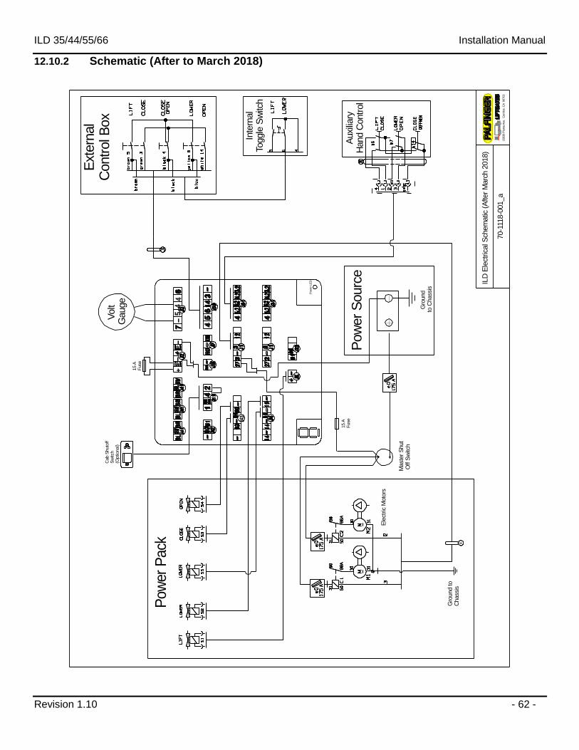
12.10.2 Schematic (After to March 2018)
15939 P
ium
a A
ve. C
err
itos,
CA
90703
70-1
118-0
01_a
ILD
Ele
ctrica
l Sch
em
atic
(A
fter
Marc
h 2
018)
V
olt
Gauge
Pow
er
LE
D
Inte
rnal
Toggle
Sw
itch
Ext
ern
al
Contr
ol B
ox
Auxi
liary
Hand C
ontr
ol
Pow
er
Sourc
e
Gro
und
to C
hass
is
Mast
er
Shut
Off S
witc
h
15 A
Fuse
Gro
und to
Chass
is
Ele
ctric
Moto
rs
Pow
er
Pack
15 A
Fuse
Cab S
huto
ff
Sw
itch
(Optio
nal)
ILD 35/44/55/66 Installation Manual
Revision 1.10 - 63 -
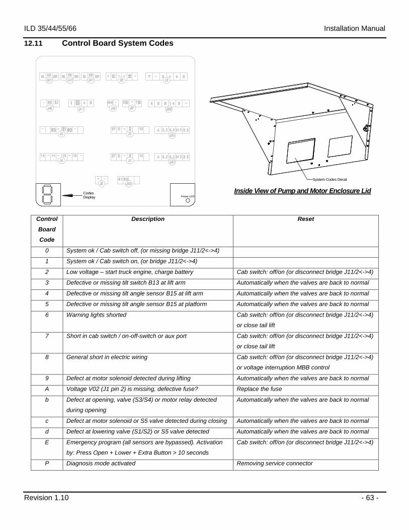
12.11 Control Board System Codes
CodesDisplay Power LED
System Codes Decal
Inside View of Pump and Motor Enclosure Lid
Control
Board
Code
Description Reset
0 System ok / Cab switch off, (or missing bridge J11/2<->4)
1 System ok / Cab switch on, (or bridge J11/2<->4)
2 Low voltage – start truck engine, charge battery Cab switch: off/on (or disconnect bridge J11/2<->4)
3 Defective or missing tilt switch B13 at lift arm Automatically when the valves are back to normal
4 Defective or missing tilt angle sensor B15 at lift arm Automatically when the valves are back to normal
5 Defective or missing tilt angle sensor B15 at platform Automatically when the valves are back to normal
6 Warning lights shorted Cab switch: off/on (or disconnect bridge J11/2<->4)
or close tail lift
7 Short in cab switch / on-off-switch or aux port Cab switch: off/on (or disconnect bridge J11/2<->4)
or close tail lift
8 General short in electric wiring Cab switch: off/on (or disconnect bridge J11/2<->4)
or voltage interruption MBB control
9 Defect at motor solenoid detected during lifting Automatically when the valves are back to normal
A Voltage V02 (J1 pin 2) is missing, defective fuse? Replace the fuse
b Defect at opening, valve (S3/S4) or motor relay detected
during opening
Automatically when the valves are back to normal
c Defect at motor solenoid or S5 valve detected during closing Automatically when the valves are back to normal
d Defect at lowering valve (S1/S2) or S5 valve detected Automatically when the valves are back to normal
E Emergency program (all sensors are bypassed). Activation
by: Press Open + Lower + Extra Button > 10 seconds
Cab switch: off/on (or disconnect bridge J11/2<->4)
P Diagnosis mode activated Removing service connector
ILD 35/44/55/66 Installation Manual
Revision 1.10 - 64 -
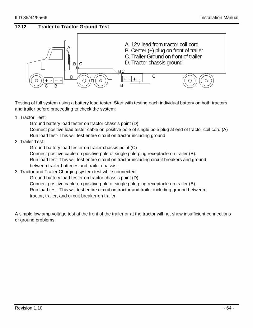
12.12 Trailer to Tractor Ground Test
A. 12V lead from tractor coil cordB. Center (+) plug on front of trailerC. Trailer Ground on front of trailerD. Tractor chassis ground
A
+ - + -+ - + -C
B
CB
BC
D
CB
Testing of full system using a battery load tester. Start with testing each individual battery on both tractors
and trailer before proceeding to check the system:
1. Tractor Test:
Ground battery load tester on tractor chassis point (D)
Connect positive load tester cable on positive pole of single pole plug at end of tractor coil cord (A)
Run load test- This will test entire circuit on tractor including ground
2. Trailer Test:
Ground battery load tester on trailer chassis point (C)
Connect positive cable on positive pole of single pole plug receptacle on trailer (B).
Run load test- This will test entire circuit on tractor including circuit breakers and ground
between trailer batteries and trailer chassis.
3. Tractor and Trailer Charging system test while connected:
Ground battery load tester on tractor chassis point (D)
Connect positive cable on positive pole of single pole plug receptacle on trailer (B).
Run load test- This will test entire circuit on tractor and trailer including ground between
tractor, trailer, and circuit breaker on trailer.
A simple low amp voltage test at the front of the trailer or at the tractor will not show insufficient connections
or ground problems.
ILD 35/44/55/66 Installation Manual
Revision 1.10 - 65 -
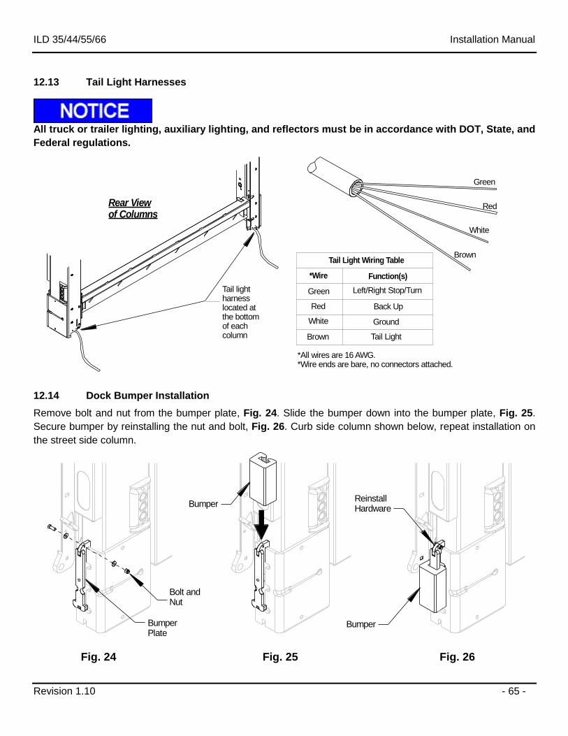
12.13 Tail Light Harnesses
All truck or trailer lighting, auxiliary lighting, and reflectors must be in accordance with DOT, State, and
Federal regulations.
Green
Red
White
Brown
Tail light harnesslocated atthe bottomof each column
Rear Viewof Columns
Tail Light Wiring Table
Green
Red
White
Brown
*Wire Function(s)
Left/Right Stop/Turn
Back Up
Ground
Tail Light
*All wires are 16 AWG.*Wire ends are bare, no connectors attached.
12.14 Dock Bumper Installation
Remove bolt and nut from the bumper plate, Fig. 24. Slide the bumper down into the bumper plate, Fig. 25.
Secure bumper by reinstalling the nut and bolt, Fig. 26. Curb side column shown below, repeat installation on
the street side column.
Bumper
Bolt andNut
BumperBumperPlate
ReinstallHardware
Fig. 24 Fig. 25 Fig. 26
ILD 35/44/55/66 Installation Manual
Revision 1.10 - 66 -
13 Above Floor Liftgate Installation (Optional)
13.1 Mounting the Liftgate
Read this entire section before beginning installation. The above floor installation reduces the
bed height limit of the liftgate. The maximum travel of the platform is 56”. For example: If the
gate is mounted 6” above floor, the maximum bed height lowers to 50”. Above floor
installations can be mounted a Maximum of 6” above the floor level of the vehicle.
Before positioning the liftgate; consider when measuring and centering the liftgate that the
truck or trailer may NOT be square or parallel. Special care must be taken to ensure that the
liftgate is square and parallel before welding.
Steps:
1. Level Truck: Truck should be on level and even ground. Uneven ground will give misleading
measurements and can cause body twist or racking.
2. Make sure the liftgate is properly secured: Verify the liftgate is attached safely to the lifting device. If
using a forklift to hoist the liftgate, use 4”x 4” x 24” wood spacers to keep the unit from sliding back
when lifting. This will help force the top of the liftgate tight against body for welding.
3. Place Spacers: It is recommended to use spacers to aid in positioning the liftgate’s height. Steel spacers,
such as a 6”x6” ¼” thick tube can be placed along the rear sill for a 6” above floor installation. For
smaller above floor heights, use smaller spacers. These spacers should be placed where the alignment
plates will land. The spacers should not be used to support the full weight of the liftgate, but only to aid
in setting the height of the liftgate.
ILD 35/44/55/66 Installation Manual
Revision 1.10 - 67 -
Bed Level
Forklift not shownBed Height Support Channel
4x4x24 Wood block
Forklift forks
90°
Spacer
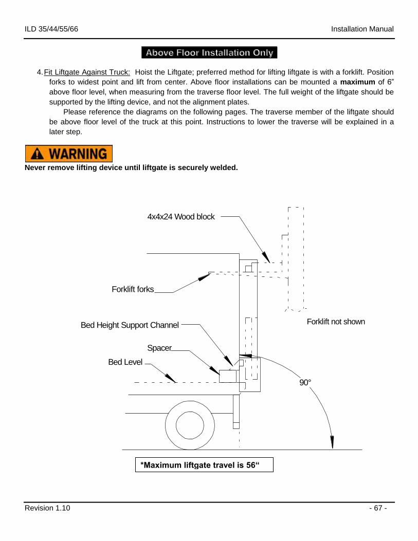
4. Fit Liftgate Against Truck: Hoist the Liftgate; preferred method for lifting liftgate is with a forklift. Position
forks to widest point and lift from center. Above floor installations can be mounted a maximum of 6”
above floor level, when measuring from the traverse floor level. The full weight of the liftgate should be
supported by the lifting device, and not the alignment plates.
Please reference the diagrams on the following pages. The traverse member of the liftgate should
be above floor level of the truck at this point. Instructions to lower the traverse will be explained in a
later step.
Never remove lifting device until liftgate is securely welded.
*Maximum liftgate travel is 56“
ILD 35/44/55/66 Installation Manual
Revision 1.10 - 68 -
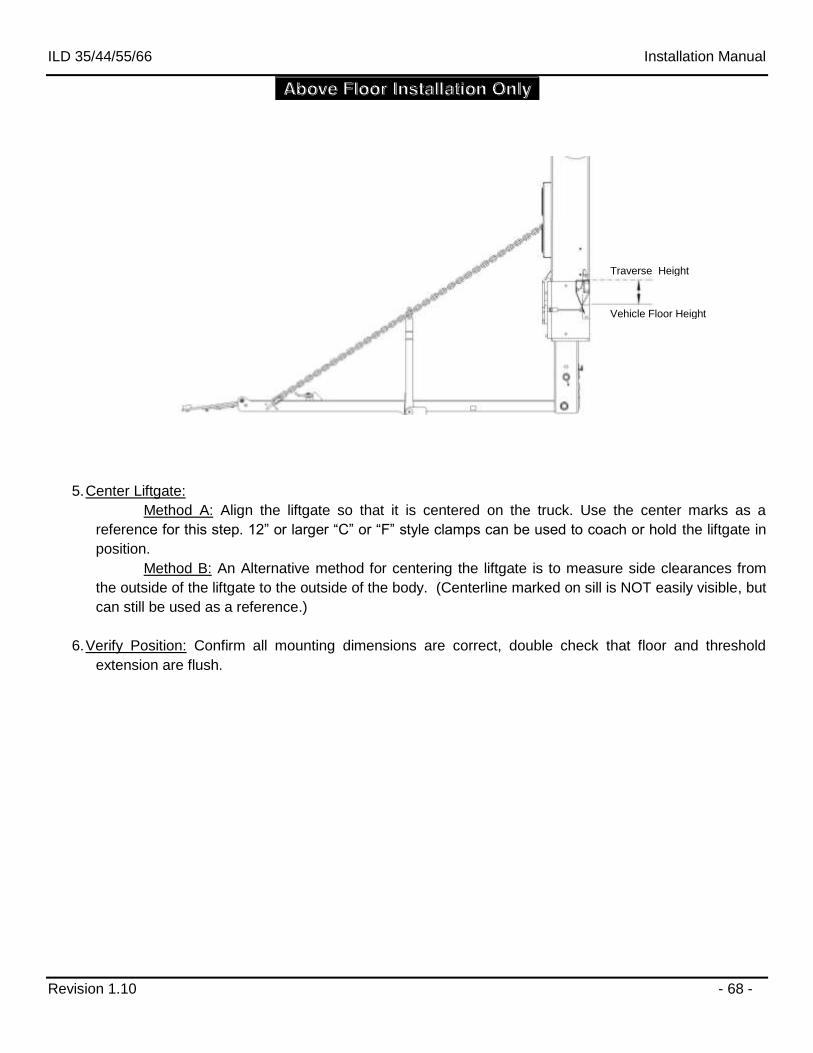
5. Center Liftgate:
Method A: Align the liftgate so that it is centered on the truck. Use the center marks as a
reference for this step. 12” or larger “C” or “F” style clamps can be used to coach or hold the liftgate in
position.
Method B: An Alternative method for centering the liftgate is to measure side clearances from
the outside of the liftgate to the outside of the body. (Centerline marked on sill is NOT easily visible, but
can still be used as a reference.)
6. Verify Position: Confirm all mounting dimensions are correct, double check that floor and threshold
extension are flush.
Vehicle Floor Height
Traverse Height
ILD 35/44/55/66 Installation Manual
Revision 1.10 - 69 -
13.2 Check Liftgate Dimensions
Steps:
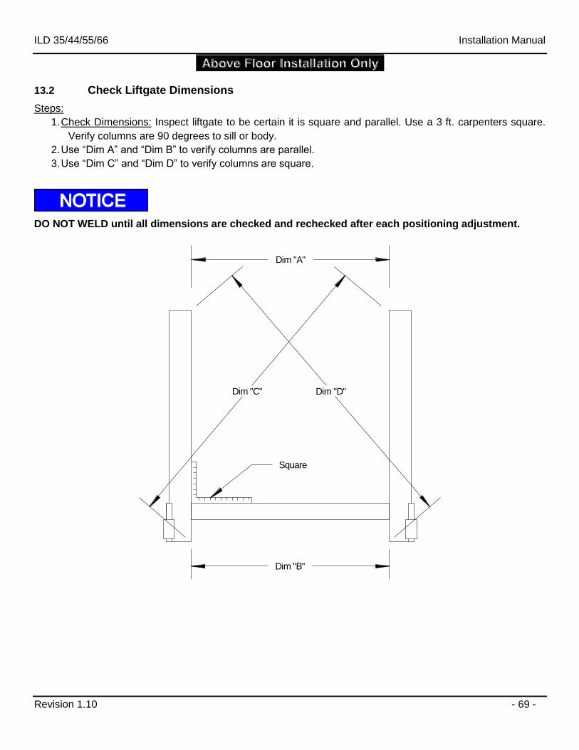
1. Check Dimensions: Inspect liftgate to be certain it is square and parallel. Use a 3 ft. carpenters square.
Verify columns are 90 degrees to sill or body.
2. Use “Dim A” and “Dim B” to verify columns are parallel.
3. Use “Dim C” and “Dim D” to verify columns are square.
DO NOT WELD until all dimensions are checked and rechecked after each positioning adjustment.
Dim "A"
Dim "B"
Dim "D"Dim "C"
Square
ILD 35/44/55/66 Installation Manual
Revision 1.10 - 70 -
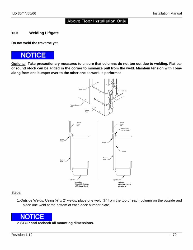
13.3 Welding Liftgate
Do not weld the traverse yet.
Optional: Take precautionary measures to ensure that columns do not toe-out due to welding. Flat bar
or round stock can be added in the corner to minimize pull from the weld. Maintain tension with come
along from one bumper over to the other one as work is performed.
VehicleCornerPost
Flatbar
VehicleCornerPost
Vehicle CornerPost with Radius
BumperPlate
BumperPlate
Vehicle CornerPost
Light Box
Light Box
Top ViewStree Side Columnwith Flatbar
Top ViewStree Side Columnwith Round Stock
RoundStock
BumperPlate
Light Box
Column
Column
Steps:
1. Outside Welds: Using ¼” x 2” welds, place one weld ½” from the top of each column on the outside and
place one weld at the bottom of each dock bumper plate.
2. STOP and recheck all mounting dimensions.
ILD 35/44/55/66 Installation Manual
Revision 1.10 - 71 -
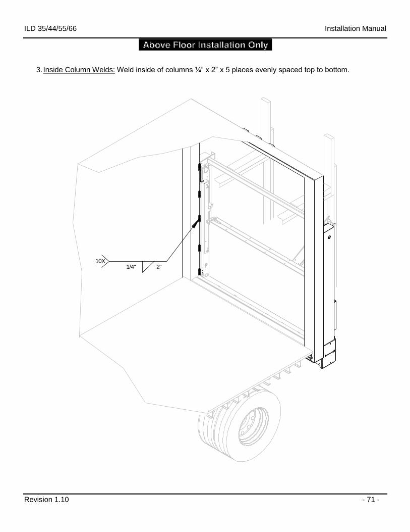
3. Inside Column Welds: Weld inside of columns ¼” x 2” x 5 places evenly spaced top to bottom.
1/4" 2"10X
ILD 35/44/55/66 Installation Manual
Revision 1.10 - 72 -
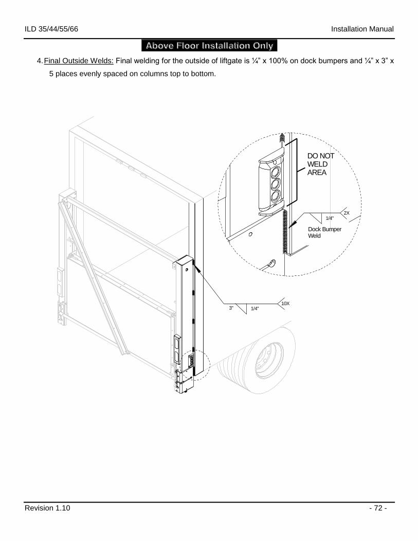
4. Final Outside Welds: Final welding for the outside of liftgate is ¼” x 100% on dock bumpers and ¼” x 3” x
5 places evenly spaced on columns top to bottom.
2X
DO NOTWELDAREA
1/4"3"10X
1/4"
Dock BumperWeld
ILD 35/44/55/66 Installation Manual
Revision 1.10 - 73 -
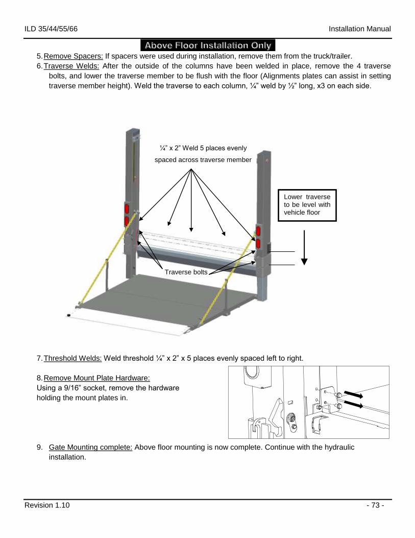
5. Remove Spacers: If spacers were used during installation, remove them from the truck/trailer.
6. Traverse Welds: After the outside of the columns have been welded in place, remove the 4 traverse
bolts, and lower the traverse member to be flush with the floor (Alignments plates can assist in setting
traverse member height). Weld the traverse to each column, ¼” weld by ½” long, x3 on each side.
7. Threshold Welds: Weld threshold ¼” x 2” x 5 places evenly spaced left to right.
8. Remove Mount Plate Hardware:
Using a 9/16” socket, remove the hardware
holding the mount plates in.
9. Gate Mounting complete: Above floor mounting is now complete. Continue with the hydraulic
installation.
Lower traverse to be level with vehicle floor
¼” x 2” Weld 5 places evenly
spaced across traverse member
Traverse bolts
ILD 35/44/55/66 Installation Manual
Revision 1.10 - 74 -
14 Lubrication
Proper lubrication will help ensure a long trouble free service life for the PALFINGER ILD+. Therefore, the
liftgate should be lubricated at the same time as the truck/trailer. Grease more frequently if the lift gate is
heavily used or whenever the pivot points appear to be dry. Average ILD plus use is considered 25 cycles per
day or 500 cycles per month. Lubricate the gate at least every 3 months or 1500 cycles, whichever comes first.
DO NOT grease the “Slider Bearings” or “Columns” or “Runners”, as this will VOID your
WARRANTY on the slide bearings. Lubricate liftgate per instructions in this chapter prior to
release to service.
All Units:
There are 12 grease fittings to maintain.
Use a light penetrating oil on closing aids. For power closing units, grease upper & lower pivot mounting
points.
Bottle Gas Units:
For units with the Bottle Gas Options, there are an additional 8 grease fittings, and additional 8 locations that
require light penetrating oil.
Check the oil level in the tank. The level should be 1.5” below the top of the reservoir when the platform is
opened and on the ground. Use a good quality hydraulic fluid, ISO 32. Change oil at least once a year,
preferably in the fall before the weather gets cold. The operation of the liftgate will accumulate condensation
and some dirt which can interfere with the liftgate functions.
ILD 35/44/55/66 Installation Manual
Revision 1.10 - 75 -
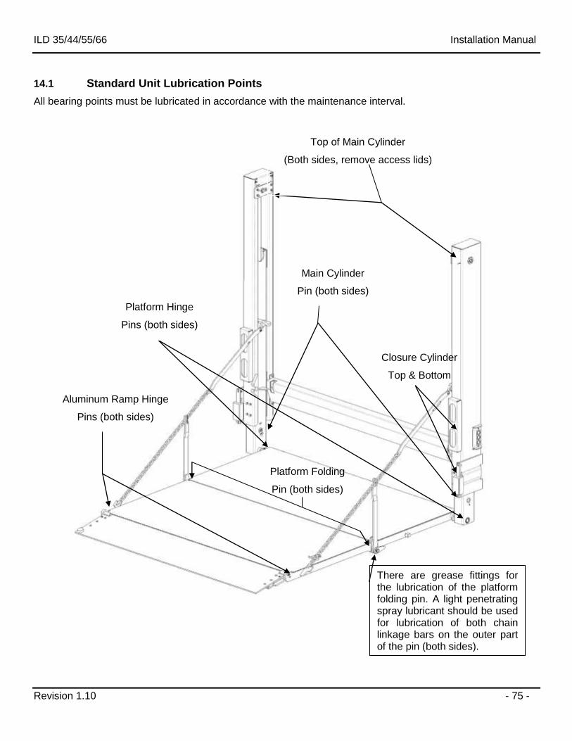
14.1 Standard Unit Lubrication Points
All bearing points must be lubricated in accordance with the maintenance interval.
Platform Hinge
Pins (both sides)
Platform Folding
Pin (both sides)
Aluminum Ramp Hinge
Pins (both sides)
Top of Main Cylinder
(Both sides, remove access lids)
Main Cylinder
Pin (both sides)
Closure Cylinder
Top & Bottom
There are grease fittings for the lubrication of the platform folding pin. A light penetrating spray lubricant should be used for lubrication of both chain linkage bars on the outer part of the pin (both sides).
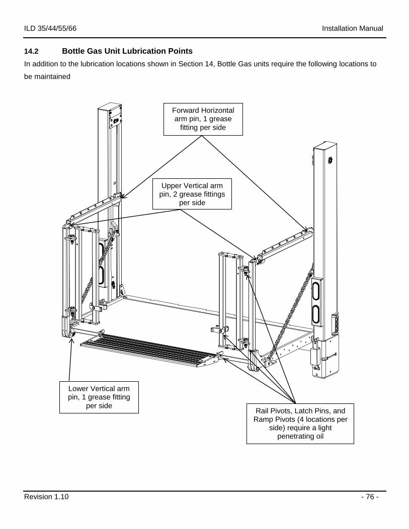
ILD 35/44/55/66 Installation Manual
Revision 1.10 - 76 -
14.2 Bottle Gas Unit Lubrication Points
In addition to the lubrication locations shown in Section 14, Bottle Gas units require the following locations to
be maintained
Forward Horizontal arm pin, 1 grease
fitting per side
Upper Vertical arm pin, 2 grease fittings
per side
Lower Vertical arm pin, 1 grease fitting
per side Rail Pivots, Latch Pins, and
Ramp Pivots (4 locations per side) require a light
penetrating oil
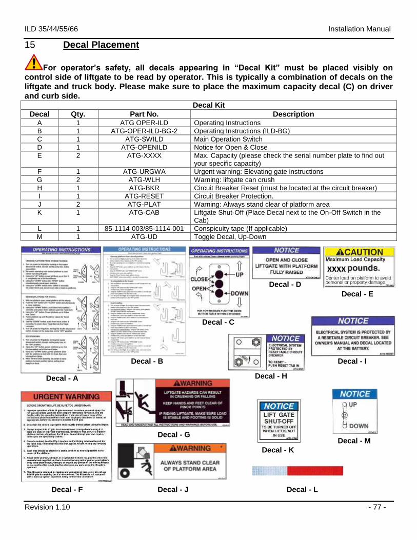
ILD 35/44/55/66 Installation Manual
Revision 1.10 - 77 -
15 Decal Placement
For operator’s safety, all decals appearing in “Decal Kit” must be placed visibly on control side of liftgate to be read by operator. This is typically a combination of decals on the liftgate and truck body. Please make sure to place the maximum capacity decal (C) on driver and curb side.
Decal Kit
Decal Qty. Part No. Description A 1 ATG OPER-ILD Operating Instructions
B 1 ATG-OPER-ILD-BG-2 Operating Instructions (ILD-BG)
C 1 ATG-SWILD Main Operation Switch
D 1 ATG-OPENILD Notice for Open & Close
E 2 ATG-XXXX Max. Capacity (please check the serial number plate to find out your specific capacity)
F 1 ATG-URGWA Urgent warning: Elevating gate instructions
G 2 ATG-WLH Warning: liftgate can crush
H 1 ATG-BKR Circuit Breaker Reset (must be located at the circuit breaker)
I 1 ATG-RESET Circuit Breaker Protection.
J 2 ATG-PLAT Warning: Always stand clear of platform area
K 1 ATG-CAB Liftgate Shut-Off (Place Decal next to the On-Off Switch in the Cab)
L 1 85-1114-003/85-1114-001 Conspicuity tape (If applicable)
M 1 ATG-UD Toggle Decal, Up-Down
Decal - A
Decal - B
Decal - D
Decal - G
Decal - H
Decal - F Decal - L
Decal - I
Decal - C
Decal - E
Decal - J
Decal - K
Decal - M
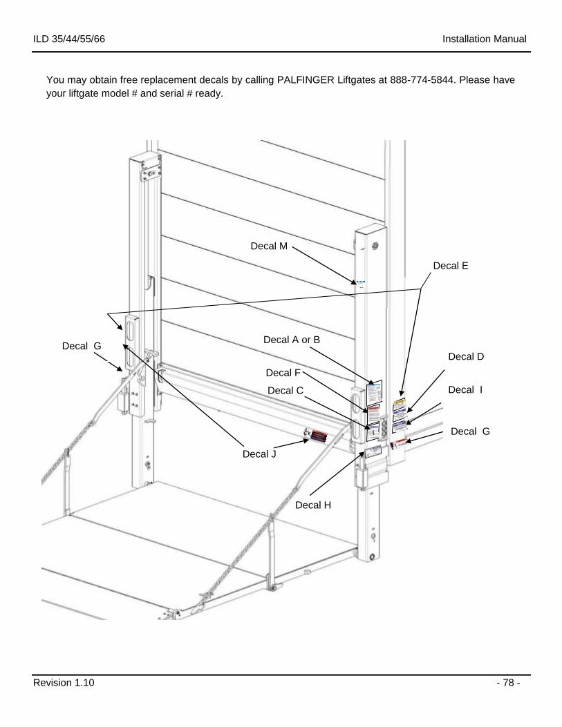
ILD 35/44/55/66 Installation Manual
Revision 1.10 - 78 -
Decal F
Decal A or B
Decal C Decal I
Decal D
Decal J
Decal H
Decal E
Decal G
Decal G
You may obtain free replacement decals by calling PALFINGER Liftgates at 888-774-5844. Please have
your liftgate model # and serial # ready.
Decal M
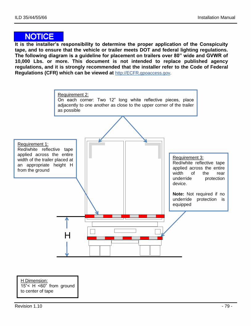
ILD 35/44/55/66 Installation Manual
Revision 1.10 - 79 -
It is the installer’s responsibility to determine the proper application of the Conspicuity tape, and to ensure that the vehicle or trailer meets DOT and federal lighting regulations. The following diagram is a guideline for placement on trailers over 80” wide and GVWR of 10,000 Lbs. or more. This document is not intended to replace published agency regulations, and it is strongly recommended that the installer refer to the Code of Federal
Regulations (CFR) which can be viewed at http://ECFR.gpoaccess.gov.
H Dimension: 15”< H <60” from ground to center of tape
Requirement 3: Red/white reflective tape applied across the entire width of the rear underride protection device. Note: Not required if no underride protection is equipped
Requirement 2: On each corner: Two 12” long white reflective pieces, place adjacently to one another as close to the upper corner of the trailer as possible
Requirement 1: Red/white reflective tape applied across the entire width of the trailer placed at an appropriate height H from the ground
H
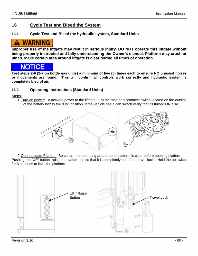
ILD 35/44/55/66 Installation Manual
Revision 1.10 - 80 -
16 Cycle Test and Bleed the System
16.1 Cycle Test and Bleed the hydraulic system, Standard Units
Improper use of the liftgate may result in serious injury. DO NOT operate this liftgate without being properly instructed and fully understanding the Owner’s manual. Platform may crush or pinch. Make certain area around liftgate is clear during all times of operation.
Test steps 2-9 (2-7 on bottle gas units) a minimum of five (5) times each to ensure NO unusual noises or movements are found. This will confirm all controls work correctly and hydraulic system is completely bled of air.
16.2 Operating Instructions (Standard Units)
Steps: 1. Turn on power: To activate power to the liftgate, turn the master disconnect switch located on the outside
of the battery box to the “ON” position. If the vehicle has a cab switch verify that its turned ON also.
Cab ShutoffSwitch
MasterShutoffSwitch
2. Open Liftgate Platform: Be certain the operating area around platform is clear before opening platform.
Pushing the “UP” button, raise the platform up so that it is completely out of the travel locks. Hold the up switch for 5 seconds to level the platform.
UP / Raise Button Travel Lock
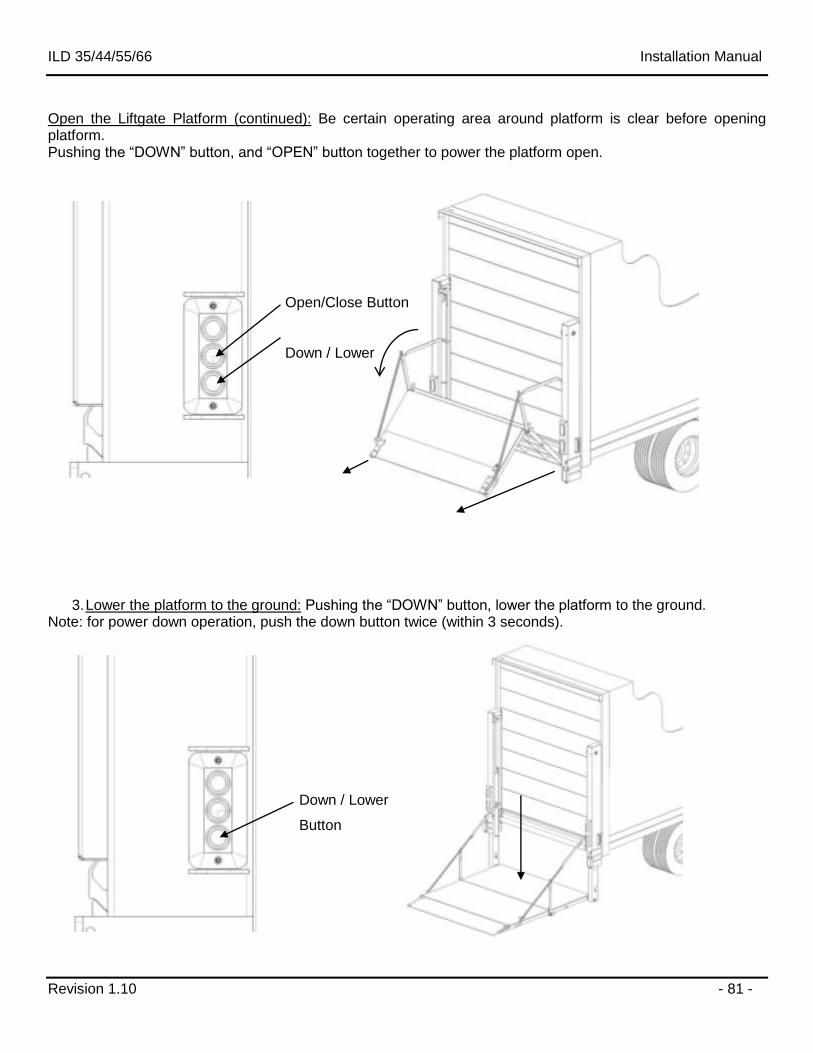
ILD 35/44/55/66 Installation Manual
Revision 1.10 - 81 -
Open the Liftgate Platform (continued): Be certain operating area around platform is clear before opening platform. Pushing the “DOWN” button, and “OPEN” button together to power the platform open.
3. Lower the platform to the ground: Pushing the “DOWN” button, lower the platform to the ground. Note: for power down operation, push the down button twice (within 3 seconds).
Open/Close Button
Down / Lower
Button
Down / Lower
Button
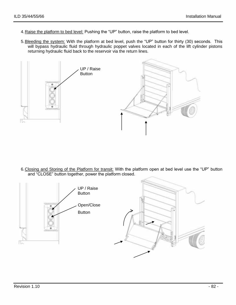
ILD 35/44/55/66 Installation Manual
Revision 1.10 - 82 -
4. Raise the platform to bed level: Pushing the “UP” button, raise the platform to bed level.
5. Bleeding the system: With the platform at bed level, push the “UP” button for thirty (30) seconds. This will bypass hydraulic fluid through hydraulic poppet valves located in each of the lift cylinder pistons returning hydraulic fluid back to the reservoir via the return lines.
6. Closing and Storing of the Platform for transit: With the platform open at bed level use the “UP” button and “CLOSE” button together, power the platform closed.
UP / Raise Button
UP / Raise Button
Open/Close
Button
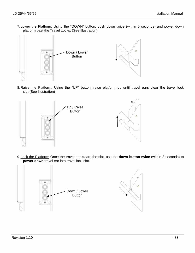
ILD 35/44/55/66 Installation Manual
Revision 1.10 - 83 -
7. Lower the Platform: Using the “DOWN” button, push down twice (within 3 seconds) and power down platform past the Travel Locks. (See Illustration)
8. Raise the Platform: Using the “UP” button, raise platform up until travel ears clear the travel lock
slot.(See Illustration)
9. Lock the Platform: Once the travel ear clears the slot, use the down button twice (within 3 seconds) to power down travel ear into travel lock slot.
Down / Lower Button
Down / Lower Button
Up / Raise Button
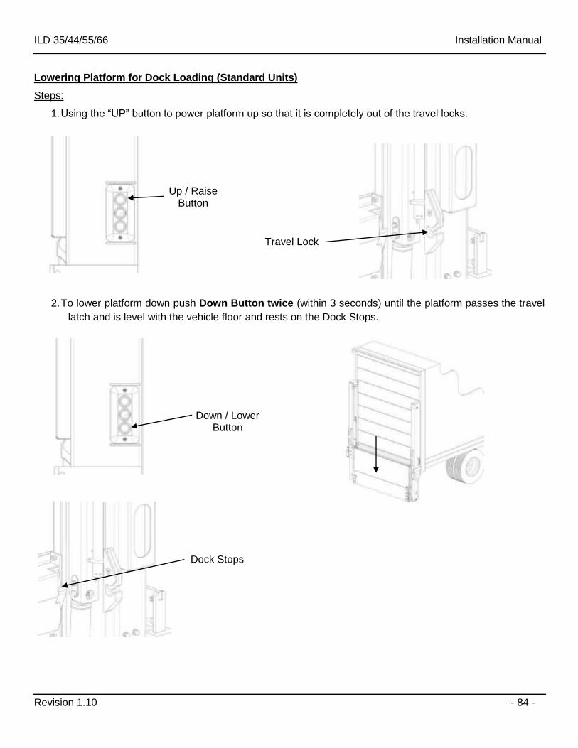
ILD 35/44/55/66 Installation Manual
Revision 1.10 - 84 -
Lowering Platform for Dock Loading (Standard Units)
Steps:
1. Using the “UP” button to power platform up so that it is completely out of the travel locks.
2. To lower platform down push Down Button twice (within 3 seconds) until the platform passes the travel
latch and is level with the vehicle floor and rests on the Dock Stops.
Up / Raise Button
Travel Lock
Dock Stops
Down / Lower Button
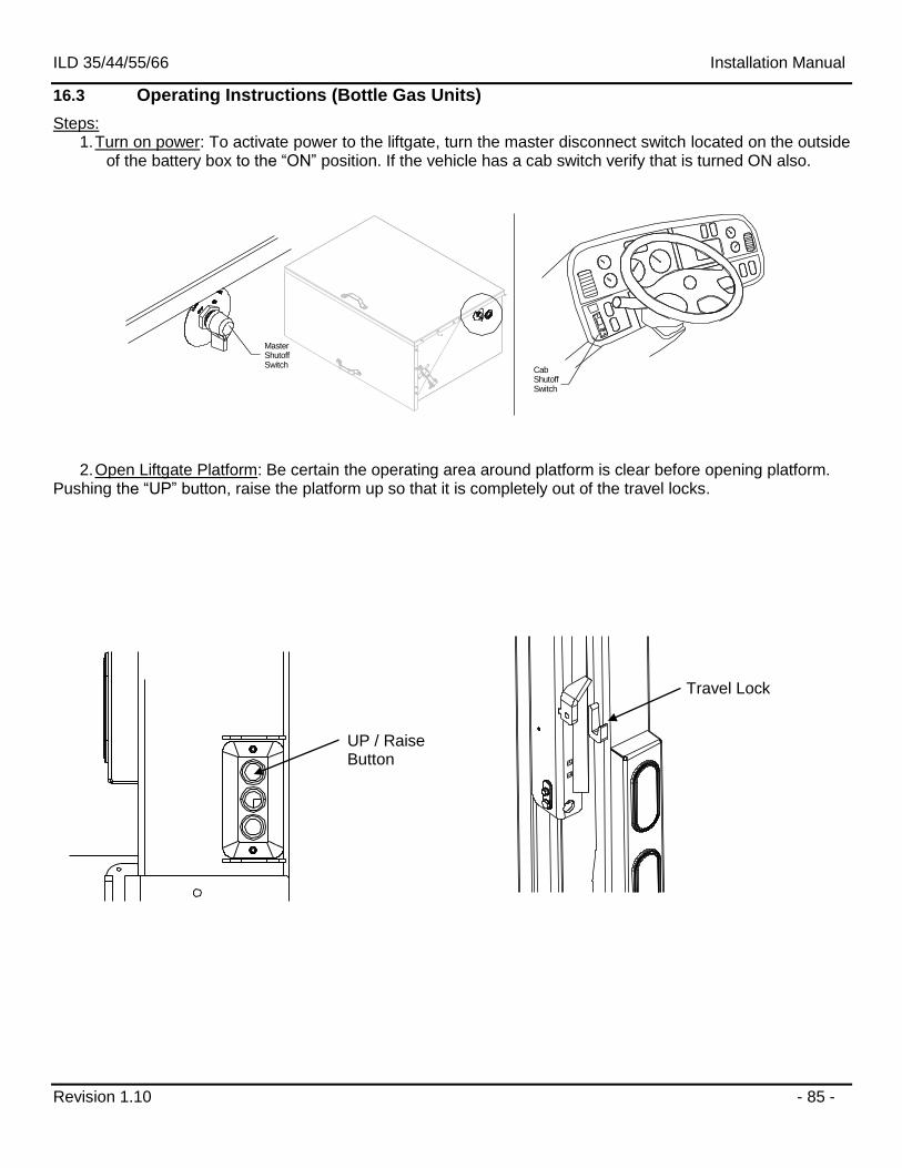
ILD 35/44/55/66 Installation Manual
Revision 1.10 - 85 -
16.3 Operating Instructions (Bottle Gas Units)
Steps: 1. Turn on power: To activate power to the liftgate, turn the master disconnect switch located on the outside
of the battery box to the “ON” position. If the vehicle has a cab switch verify that is turned ON also.
Cab ShutoffSwitch
MasterShutoffSwitch
2. Open Liftgate Platform: Be certain the operating area around platform is clear before opening platform. Pushing the “UP” button, raise the platform up so that it is completely out of the travel locks.
UP / Raise Button
Travel Lock
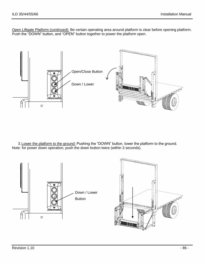
ILD 35/44/55/66 Installation Manual
Revision 1.10 - 86 -
Open Liftgate Platform (continued): Be certain operating area around platform is clear before opening platform. Push the “DOWN” button, and “OPEN” button together to power the platform open.
3. Lower the platform to the ground: Pushing the “DOWN” button, lower the platform to the ground. Note: for power down operation, push the down button twice (within 3 seconds).
Open/Close Button
Down / Lower
Button
Down / Lower
Button
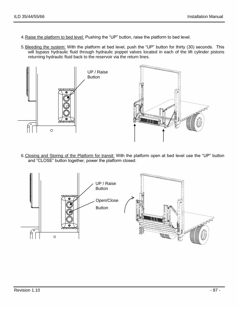
ILD 35/44/55/66 Installation Manual
Revision 1.10 - 87 -
4. Raise the platform to bed level: Pushing the “UP” button, raise the platform to bed level.
5. Bleeding the system: With the platform at bed level, push the “UP” button for thirty (30) seconds. This will bypass hydraulic fluid through hydraulic poppet valves located in each of the lift cylinder pistons returning hydraulic fluid back to the reservoir via the return lines.
6. Closing and Storing of the Platform for transit: With the platform open at bed level use the “UP” button and “CLOSE” button together, power the platform closed.
UP / Raise Button
UP / Raise Button
Open/Close
Button
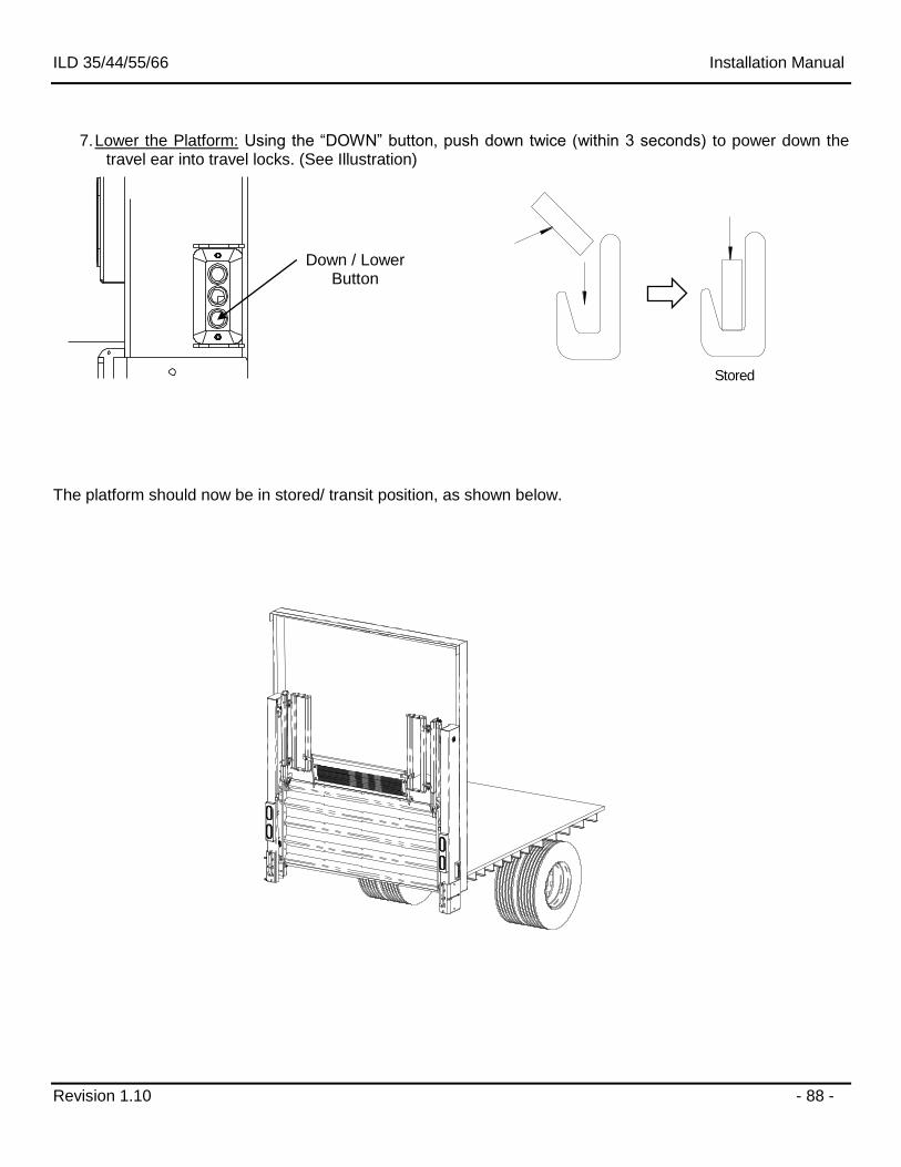
ILD 35/44/55/66 Installation Manual
Revision 1.10 - 88 -
Stored
7. Lower the Platform: Using the “DOWN” button, push down twice (within 3 seconds) to power down the
travel ear into travel locks. (See Illustration) The platform should now be in stored/ transit position, as shown below.
Down / Lower Button
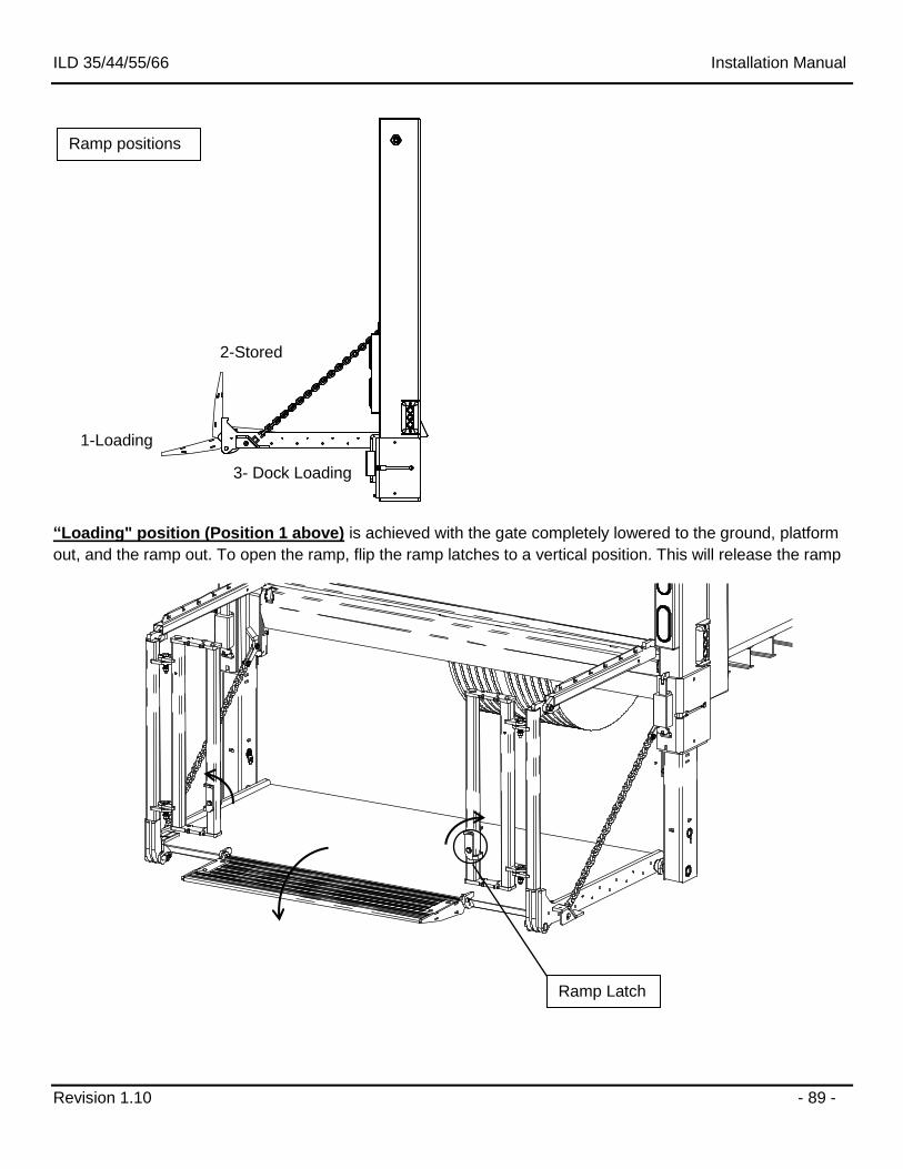
ILD 35/44/55/66 Installation Manual
Revision 1.10 - 89 -
“Loading" position (Position 1 above) is achieved with the gate completely lowered to the ground, platform
out, and the ramp out. To open the ramp, flip the ramp latches to a vertical position. This will release the ramp
Ramp Latch
Ramp positions
1-Loading
2-Stored
3- Dock Loading
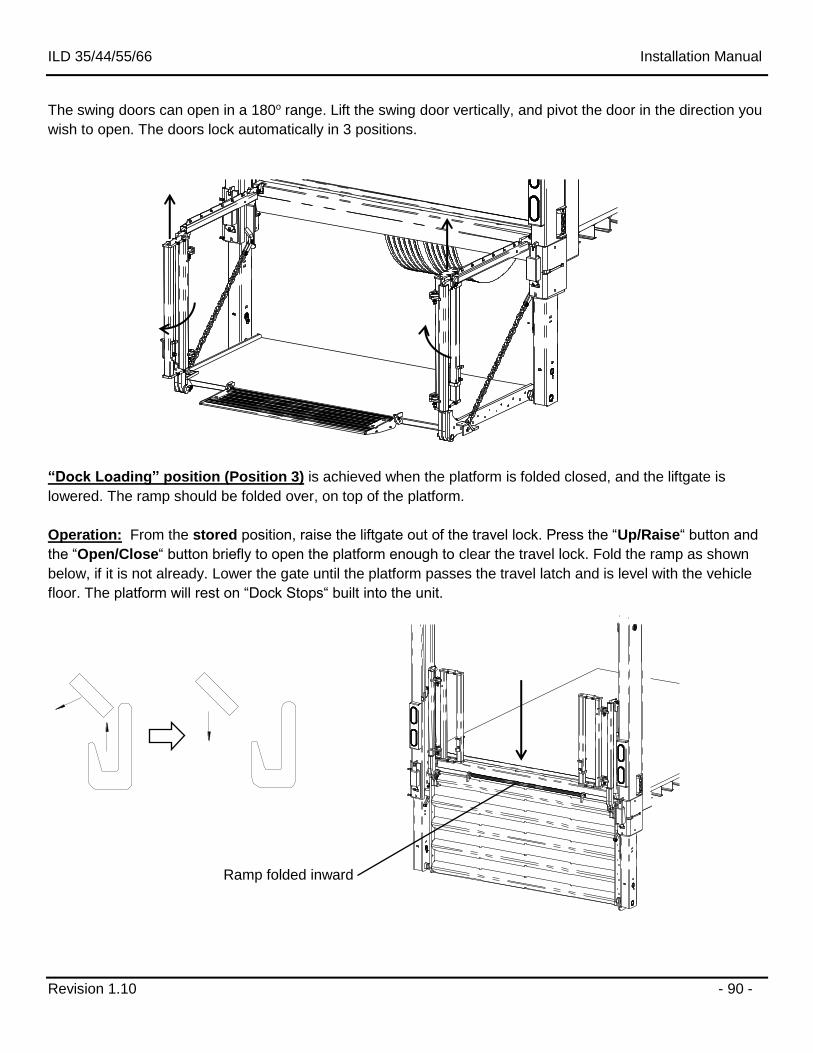
ILD 35/44/55/66 Installation Manual
Revision 1.10 - 90 -
The swing doors can open in a 180o range. Lift the swing door vertically, and pivot the door in the direction you
wish to open. The doors lock automatically in 3 positions.
“Dock Loading” position (Position 3) is achieved when the platform is folded closed, and the liftgate is
lowered. The ramp should be folded over, on top of the platform.
Operation: From the stored position, raise the liftgate out of the travel lock. Press the “Up/Raise“ button and
the “Open/Close“ button briefly to open the platform enough to clear the travel lock. Fold the ramp as shown
below, if it is not already. Lower the gate until the platform passes the travel latch and is level with the vehicle
floor. The platform will rest on “Dock Stops“ built into the unit.
Ramp folded inward
ILD 35/44/55/66 Installation Manual
Revision 1.10 - 91 -
17 Final Inspection Check List
Liftgate failure or malfunction could result in property damage, personal injury or death if you fail to check each of the following items listed. DO NOT USE the liftgate if any of the following points are NOT verified and checked. Installation is NOT complete and all WARRANTIES are VOID if you have not checked and verified all items listed on this inspection sheet. Inspection sheet is to be filed at the facility where liftgate was installed. Structural Inspection
Lifting braces and shipping stand are removed from the liftgate.
All welds are 100% complete per this manual.
All nuts, bolts, mounting hardware, pins, chain anchors are tight.
All mounting dimensions are correct and liftgate is square and parallel per this manual. Hydraulic Inspection
Pump reservoir is filled 1.5" from top when platform is opened at bed level.
Hydraulic components and connections do not leak. (Should be checked after unit is hydraulically locked for five (5) minutes.)
All hydraulic lines are secured with cable ties, hoses clamps, or other fasteners and are away from sharp edges and moving parts. Electrical Inspection
Battery cable(s) attached and clamped tight and dielectric grease is used to seal all connections.
Master disconnect switch is installed and operating properly. All electrical lines are secured with cable ties, hoses clamps, or other fasteners and are away from sharp edges and moving parts.
Circuit Breakers installed and wired per instructions. Lights wired properly and operate per DOT, State, and Federal requirements.
Load test has been performed as explained in Section 12.12 Trailer to Tractor Ground Test.
Measure battery voltages: Flooded Batteries = 12.6V; AGM Batteries = 12.8V. Operational Inspection
All decals are in place and legible per instructions. All pivot points are lubricated per instructions. Platform secures properly in its stowed position latches. Platform travels up and down smoothly and freely, without any hesitation or unusual noises.
Platform is level with the floor of the vehicle when raised completely.
Platform is level across the fold when opened. Platform rests on the ground evenly when lowered completely. Platform opens and closes properly and at correct speed. (2 to 4 inches per second) The liftgate serial number and model number are documented on the inside of the Owner’s Manual (pg.iii). Owner’s Manual has been provided to end user or is placed inside the hydraulic enclosure. Supervisor has demonstrated the instructions in the Owner’s Manual to the customer/driver upon delivery. Inspection Information (Please Print): Name:_______________________________________________Signature:_______________________________
Completed by: ________________________________Title: ______________________Date:_________________
Liftgate Model: __________________________Liftgate Serial Number: ___________________________________
Related Documents


