ELK-M1XRF2H v2 Wireless Receiver and Input Expander Compatible with Wireless Transmitters that operate on the 345MHz Frequency and adhere to the Ademco 5800 protocol. A list of known compatible transmitters can be found inside. INSTALLATION MANUAL L675 Rev. C 3/14/2019 IMPORTANT NOTE: Please consult the Elk M1 Dealer website for downloads of the latest M1 Control firmware and ElkRP Software. For compatibility with this Receiver we recommend the M1 Control be operating firmware version 5.3.10 or higher and the ElkRP software be version 2.0.36 or higher. TM Ademco is a registered trademark belonging to Honeywell.

Welcome message from author
This document is posted to help you gain knowledge. Please leave a comment to let me know what you think about it! Share it to your friends and learn new things together.
Transcript
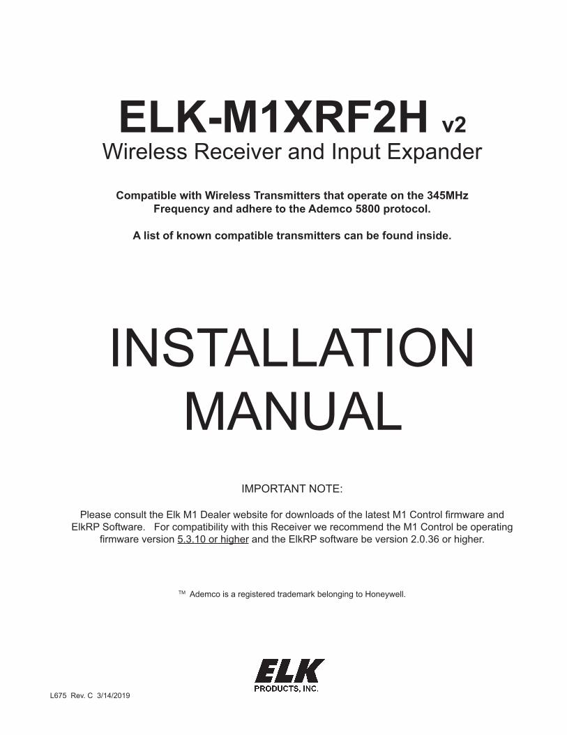
ELK-M1XRF2H v2Wireless Receiver and Input Expander
Compatible with Wireless Transmitters that operate on the 345MHz Frequency and adhere to the Ademco 5800 protocol.
A list of known compatible transmitters can be found inside.
INSTALLATION MANUAL
L675 Rev. C 3/14/2019
IMPORTANT NOTE:
Please consult the Elk M1 Dealer website for downloads of the latest M1 Control firmware and ElkRP Software. For compatibility with this Receiver we recommend the M1 Control be operating
firmware version 5.3.10 or higher and the ElkRP software be version 2.0.36 or higher.
TM Ademco is a registered trademark belonging to Honeywell.
Page 2 ELK-M1XRF2H v2 Installation Manual
Table of Contents
Installation and Setup .................................................................................................................... 3Setting the Data Bus Address of the Wireless Receiver and the Starting Wireless Zone ID .................... 4Data Bus Enrollment:: .............................................................................................................................. 5Examples of Data Bus Address Settings .................................................................................................. 5
Operation ......................................................................................................................................... 6How Received Transmissions are handled: ............................................................................................. 6Diagnostic LEDs: ...................................................................................................................................... 6Transmitter (RF) Level Checking [Signal Strength]: ................................................................................. 6
List of Ademco 345MHz Transmitters .......................................................................................... 7Programming via Keypad ............................................................................................................ 10Appendix A - Data Bus Selection Tables .................................................................................... 12Appendix B - Examples of Zone Configurations ....................................................................... 14Appendix C - Installing Multiple Redundant Receivers ............................................................ 15
This device complies with Part 15 of FCC Rules which are designed to provide reasonable protection against such interference in a residential installation. The FCC requires the following statement for your information:
This equipment generates and uses radio frequency energy and if not installed and used properly, that is, in strict accordance with the manufacturer’s instructions, may cause Interference to radio and television reception. It has been type tested. However, there is no guarantee that interference will not occur in a particular installation. If this equipment does cause interference to radio or television reception, which can be determined by turning the equipment off and on, the user is encouraged to try to correct the interference by one or more of the following measures: * If using an indoor antenna, have a quality outdoor antenna installed. * Reorient the receiving antenna until interference is induced or eliminated. * Move the receiver away from the security control. * Move the antenna leads away from any wire runs to the security control * Have the device or controller plugged into a different outlet so that it and the receiver are on different branch circuits.If necessary, the user should consult the dealer or an experienced radio/television technician for additional suggestions. The user or installer may find a booklet titled “Interference Handbook” prepared by the Federal Communications Commission helpful: This booklet is available from the U.S. Government Printing Office, Washington, DC 20402. The user shall not make any changes or modifications to the equipment unless authorized by the Installation Instructions or Users Manual. Unauthorized changes or modifications could void the user’s authority to operate the equipment.
FEATURES: • Adds up to 144 individual wireless transmitters (zones/sensors)• Operates from the 4 wire RS485 Data Bus• Multiple Receivers (max. of 9) may be connected to a single M1 or M1EZ8 Control for redundancy and greater coverage• Compatible with wireless transmitters that operate on the 345MHz Frequency and adhere to the Ademco 5800 protocol.
SPECIFICATIONS: • Sensitivity: >105 dbm• Operating Temperature: 0 to +120 degrees F• Operating Voltage: 12 Volts D.C.• Current Draw: 52mA• Indoor Range: 300 to 500 ft. ** line of sight ** Laboratory tests have achieved greater distances, however walls and metal objects generally reduce actual operating range.
ELK-M1XRF2H v2 Installation Manual Page 3
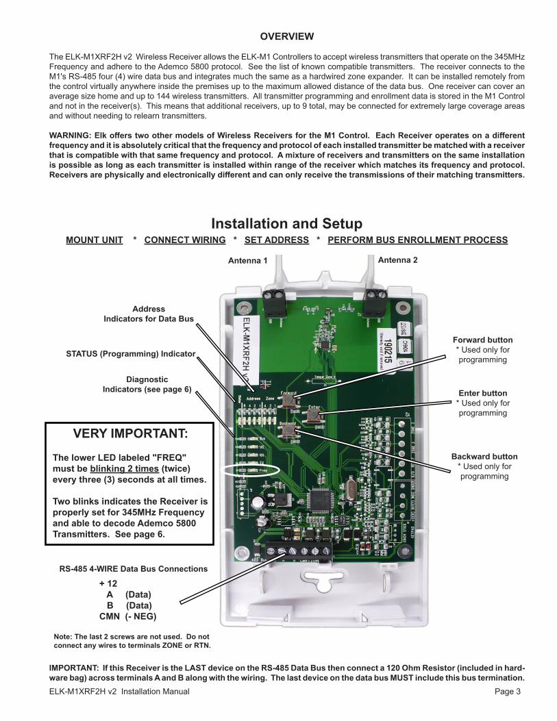
OVERVIEW
The ELK-M1XRF2H v2 Wireless Receiver allows the ELK-M1 Controllers to accept wireless transmitters that operate on the 345MHz Frequency and adhere to the Ademco 5800 protocol. See the list of known compatible transmitters. The receiver connects to the M1's RS-485 four (4) wire data bus and integrates much the same as a hardwired zone expander. It can be installed remotely from the control virtually anywhere inside the premises up to the maximum allowed distance of the data bus. One receiver can cover an average size home and up to 144 wireless transmitters. All transmitter programming and enrollment data is stored in the M1 Control and not in the receiver(s). This means that additional receivers, up to 9 total, may be connected for extremely large coverage areas and without needing to relearn transmitters.
WARNING: Elk offers two other models of Wireless Receivers for the M1 Control. Each Receiver operates on a different frequency and it is absolutely critical that the frequency and protocol of each installed transmitter be matched with a receiver that is compatible with that same frequency and protocol. A mixture of receivers and transmitters on the same installation is possible as long as each transmitter is installed within range of the receiver which matches its frequency and protocol. Receivers are physically and electronically different and can only receive the transmissions of their matching transmitters.
Installation and SetupMOUNT UNIT * CONNECT WIRING * SET ADDRESS * PERFORM BUS ENROLLMENT PROCESS
RS-485 4-WIRE Data Bus Connections
+ 12 A (Data) B (Data) CMN (- NEG)
Note: The last 2 screws are not used. Do not connect any wires to terminals ZONE or RTN.
Address Indicators for Data Bus
IMPORTANT: If this Receiver is the LAST device on the RS-485 Data Bus then connect a 120 Ohm Resistor (included in hard-ware bag) across terminals A and B along with the wiring. The last device on the data bus MUST include this bus termination.
Antenna 2Antenna 1
Diagnostic Indicators (see page 6)
Backward button * Used only for programming
Forward button * Used only for programming
Enter button * Used only for programming
VERY IMPORTANT:
The lower LED labeled "FREQ" must be blinking 2 times (twice) every three (3) seconds at all times.
Two blinks indicates the Receiver is properly set for 345MHz Frequency and able to decode Ademco 5800 Transmitters. See page 6.
STATUS (Programming) Indicator
Page 4 ELK-M1XRF2H v2 Installation Manual
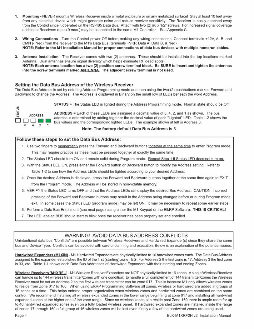
Setting the Data Bus Address of the Wireless Receiver
1. Mounting - NEVER mount a Wireless Receiver inside a metal enclosure or on any metalized surface! Stay at least 10 feet away from any electrical device which might generate noise and reduce receiver sensitivity. The Receiver is easily attached away from the Control since it operated on the RS-485 Data Bus. Attach with two (2) #6 x 1/2" screws. For increased signal coverage additional Receivers (up to 9 max.) may be connected to the same M1 Controller. See Appendix C.
2. Wiring Connections - Turn the Control power Off before making any wiring connections. Connect terminals +12V, A, B, and CMN (- Neg) from the receiver to the M1's Data Bus (terminals +VKP, Data A, Data B, & Neg).
NOTE: Refer to the M1 Installation Manual for proper connections of data bus devices with multiple homerun cables.
3. Antenna Installation - The Receiver comes with two (2) antennas. These should be installed into the top locations marked Antenna. Dual antennas ensure signal diversity which helps eliminate RF dead spots.
NOTE: Each antenna location has a two (2) position screw terminal block. Be SURE to insert and tighten the antennas into the screw terminals marked ANTENNA. The adjacent screw terminal is not used.
The Data Bus Address is set by entering Address Programming mode and then using the two (2) pushbuttons marked Forward and Backward to change the Address. The Address is displayed in Binary on the small row of LEDs beneath the word Address.
8 4
ADDRESS
WARNING! AVOID DATA BUS ADDRESS CONFLICTS Unintentional data bus "Conflicts" are possible between Wireless Receivers and Hardwired Expander(s) since they share the same bus and Device Type. Conflicts can be avoided with careful planning and execution. Below is an explanation of the potential issues.
Hardwired Expanders (M1XIN) - M1 Hardwired Expanders are physically limited to 16 hardwired zones each. The Data Bus Address assigned to the expander establishes the ID of the first (starting) zone. EG: For Address 2 the first zone is 17, Address 3 the first zone is 33, etc. Table 1-1 shows each Data Bus Addresses of Hardwired Expanders with their starting and ending Zones.
Wireless Receivers (M1XRF--) - M1 Wireless Receiver Expanders are NOT physically limited to 16 zones. A single Wireless Receiver can handle up to 144 wireless transmitter/zones with one condition: to handle a full complement of 144 transmitter/zones the Wireless Receiver must be set as Address 2 so the first wireless transmitter can be zone 017. This is because M1 only allows wireless zones to reside from Zone 017 to 160. When using ElkRP Programming Software all zones, wireless or hardwired are added in groups of 16 zones at a time. This helps enforce proper organization when wireless zones and hardwired zones are combined on the same control. We recommend installing all wireless expanded zones in the lower range beginning at zone 017 and installing all hardwired expanded zones at the higher end of the zone range. Since no wireless zones can reside past Zone 160 there is ample room for up to 48 hardwired expanded zones even on a fully loaded wireless panel. If hardwired expanded zones are installed inside the range of zones 17 through 160 a full group of 16 wireless zones will be lost even if only a few of the hardwired zones are being used.
2 1
STATUS = The Status LED is lighted during the Address Programming mode. Normal state should be Off.
ADDRESS = Each of these LEDs are assigned a decimal value of 8, 4, 2, and 1 as shown. The bus address is determined by adding together the decimal value of each "Lighted" LED. Table 1-2 shows the bus values and the corresponding lighted LEDs. The example shown at left is Address 3.
Follow these steps to set the Data Bus Address: 1. Use two fingers to momentarily press the Forward and Backward buttons together at the same time to enter Program mode. This may require practice as these must be pressed together at exactly the same time. 2. The Status LED should turn ON and remain solid during Program mode. Repeat Step 1 if Status LED does not turn on. 3. With the Status LED ON, press either the Forward button or Backward button to modify the Address setting. Refer to Table 1-2 to see how the Address LEDs should be lighted according to your desired Address. 4. Once the desired Address is displayed, press the Forward and Backward buttons together at the same time again to EXIT from the Program mode. The Address will be stored in non-volatile memory. 5. VERIFY the Status LED turns OFF and that the Address LEDs still display the desired Bus Address. CAUTION: Incorrect pressing of the Forward and Backward buttons may result in the Address being changed before or during Program mode exit. In some cases the Status LED (program mode) may be left ON. It may be necessary to repeat some earlier steps 6. Perform a Data Bus Enrollment (see next page) using either the M1 Keypad or the ElkRP Software. THIS IS CRITICAL! 7. The LED labeled BUS should start to blink once the receiver has been properly set and enrolled.
STAT
US
Note: The factory default Data Bus Address is 3

ELK-M1XRF2H v2 Installation Manual Page 5
Conflicts can exist if a group of hardwired zones are allowed to overlap or intrude where wireless sensors/zones exist. Wireless sensors/zones and hardwired zones MUST NEVER be allowed to overlap! If there is a likelihood of future wireless zone expansion then we recommend skipping up to a higher address to install a hardwired expanders. This effectively leaves open addresses for future wireless. Do NOT install any Hardwired Expanders in that open address space. Tables 1-1 and 1-2 illustrate the Data Bus Address setting of a wireless receiver while pointing out Addresses to avoid when adding or installing Hardwired Expanders.
- Never assign a Wireless Receiver and a Hardwire Expander to the same Data Bus Address. - Never assign a Hardwire Expander to any Address that correlates to Wireless Transmitter/Zones. EG: If a Control has 40
wireless transmitters/zones and the Receiver is set to Address 2 the first wireless zone will be 17 and the last will be 57. Referring to Table 1-1 we see that zone 57 correlates to Data Bus Address 4. In this example a hardwired expander CANNOT be installed at Addresses 2, 3, or 4 since those addresses correspond to Zones 17 to 64.
- Never learn a new wireless transmitter that spills over into a data bus address assigned to a Hardwired Expander.- Try to always keep wireless transmitter zones so they are contiguous and never split up by any hardwired expanded zones.
Data Bus Addresses whose zone IDs are effectively "overlapped" by wireless zones are considered "reserved" for wireless use and should not be used by a hardwired zone expander. See Appendix C.
- The maximum number of wireless zones is 144 and the last wireless zone number cannot be greater than 160.
NOTE: Consider whether the system may ever need additional wireless or hardwired zones. If the answer is yes, we suggest the data bus address assignments be strategically set to permit future growth without being forced to re-arrange the addresses at a future date or defaulting the control and starting over.
LED Display8 4 2 1
‐ ‐ ‐ ‐‐ ‐ ‐ ‐‐ ‐ ‐ ‐‐ ‐ ‐ ‐‐ ‐ ‐ ‐
Data Bus Address
23456789101112131415
Suggested Wireless "Starting Point"
Zone 17Zone 33Zone 49Zone 65Zone 81Zone 97Zone 113Zone 129Zone 145not validnot validnot validnot validnot valid
Switch SettingsS1 S2 S3 S4Off On Off Off On On Off Off Off Off On Off On Off On Off Off On On Off On On On OffOff Off Off OnOn Off Off OnOff On Off On On On Off On Off Off On OnOn Off On On‐ ‐ ‐ ‐‐ ‐ ‐ ‐
Data Bus Address
23456789101112131415
Starting and Ending Zone Numbers Zones 17 ‐ 32Zones 33 ‐ 48Zones 49 ‐ 64Zones 65 ‐ 80Zones 81 ‐ 96Zones 97 ‐ 112Zones 113 ‐ 128Zones 129 ‐ 144Zones 145 ‐ 160Zones 161 ‐ 176Zones 177 ‐ 192Zones 193 ‐ 208
not validnot valid
Table 1‐1 Table 1‐2
Wireless Receiver Expanders (M1XRF2H v2)Hardwired Zone Expanders (M1XIN)
Data Bus Enrollment:: Once the address is set and the Wireless Receiver is powered up it must be manually ENROLLED with the M1 Control. This can be performed from keypad programming "Menu 1 - Bus Module Enrollment" or ElkRP Remote Programming Software.(The steps below require an M1 LCD Keypad)1. Press the ELK key, then press 9 (or scroll up) to display 9 - Installation Programming. Press the RIGHT arrow key to select this menu. The Installer Program Code (PIN) must be entered to access this menu.2. Enter the Installer Program Code. (The default code is 172839)3. The first Installer Programming menu displayed will be "Bus Module Enrollment"4. Press the RIGHT arrow key to select this menu. "Enrolling Bus Modules" will display5. The control will transmit an enrollment message to all data bus devices, followed by a display showing the total Bus Modules that are enrolled. To view the enrolled devices and/or remove a device press the RIGHT arrow key next to the word Edit.6. Press the * or Exit keys to exit Installer Programming.
XX Bus Modules Enrolled, Edit r
Auth. Required Enter Valid Pin
01-Bus ModuleEnrollment
Examples of Data Bus Address Settings
Page 6 ELK-M1XRF2H v2 Installation Manual
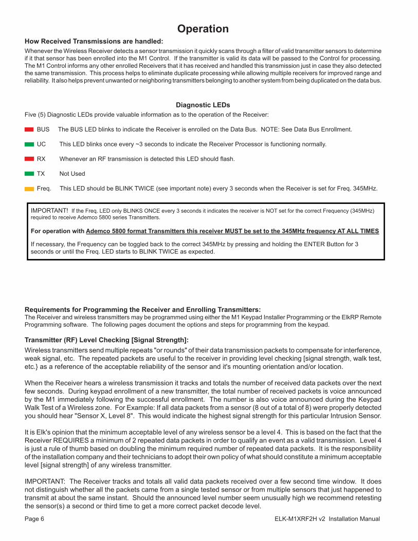
How Received Transmissions are handled:Whenever the Wireless Receiver detects a sensor transmission it quickly scans through a filter of valid transmitter sensors to determine if it that sensor has been enrolled into the M1 Control. If the transmitter is valid its data will be passed to the Control for processing. The M1 Control informs any other enrolled Receivers that it has received and handled this transmission just in case they also detected the same transmission. This process helps to eliminate duplicate processing while allowing multiple receivers for improved range and reliability. It also helps prevent unwanted or neighboring transmitters belonging to another system from being duplicated on the data bus.
Operation
Diagnostic LEDsFive (5) Diagnostic LEDs provide valuable information as to the operation of the Receiver: BUS The BUS LED blinks to indicate the Receiver is enrolled on the Data Bus. NOTE: See Data Bus Enrollment.
UC This LED blinks once every ~3 seconds to indicate the Receiver Processor is functioning normally.
RX Whenever an RF transmission is detected this LED should flash.
TX Not Used
Freq. This LED should be BLINK TWICE (see important note) every 3 seconds when the Receiver is set for Freq. 345MHz.
IMPORTANT! If the Freq. LED only BLINKS ONCE every 3 seconds it indicates the receiver is NOT set for the correct Frequency (345MHz) required to receive Ademco 5800 series Transmitters.
For operation with Ademco 5800 format Transmitters this receiver MUST be set to the 345MHz frequency AT ALL TIMES
If necessary, the Frequency can be toggled back to the correct 345MHz by pressing and holding the ENTER Button for 3 seconds or until the Freq. LED starts to BLINK TWICE as expected.
Requirements for Programming the Receiver and Enrolling Transmitters:The Receiver and wireless transmitters may be programmed using either the M1 Keypad Installer Programming or the ElkRP Remote Programming software. The following pages document the options and steps for programming from the keypad.
Transmitter (RF) Level Checking [Signal Strength]:Wireless transmitters send multiple repeats "or rounds" of their data transmission packets to compensate for interference, weak signal, etc. The repeated packets are useful to the receiver in providing level checking [signal strength, walk test, etc.} as a reference of the acceptable reliability of the sensor and it's mounting orientation and/or location.
When the Receiver hears a wireless transmission it tracks and totals the number of received data packets over the next few seconds. During keypad enrollment of a new transmitter, the total number of received packets is voice announced by the M1 immediately following the successful enrollment. The number is also voice announced during the Keypad Walk Test of a Wireless zone. For Example: If all data packets from a sensor (8 out of a total of 8) were properly detected you should hear "Sensor X, Level 8". This would indicate the highest signal strength for this particular Intrusion Sensor.
It is Elk's opinion that the minimum acceptable level of any wireless sensor be a level 4. This is based on the fact that the Receiver REQUIRES a minimum of 2 repeated data packets in order to qualify an event as a valid transmission. Level 4 is just a rule of thumb based on doubling the minimum required number of repeated data packets. It is the responsibility of the installation company and their technicians to adopt their own policy of what should constitute a minimum acceptable level [signal strength] of any wireless transmitter.
IMPORTANT: The Receiver tracks and totals all valid data packets received over a few second time window. It does not distinguish whether all the packets came from a single tested sensor or from multiple sensors that just happened to transmit at about the same instant. Should the announced level number seem unusually high we recommend retesting the sensor(s) a second or third time to get a more correct packet decode level.
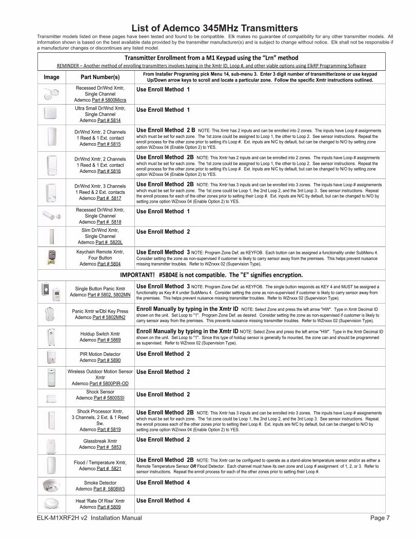
ELK-M1XRF2H v2 Installation Manual Page 7
Smoke DetectorAdemco Part # 5808W3
Ultra Small Dr/Wnd Xmtr, Single Channel
Ademco Part # 5814
Recessed Dr/Wnd Xmtr, Single Channel
Ademco Part # 5818
Recessed Dr/Wnd Xmtr, Single Channel
Ademco Part # 5800Micra
Use Enroll Method 1
Dr/Wnd Xmtr, 3 Channels 1 Reed & 2 Ext. contacts
Ademco Part # 5817
Heat 'Rate Of Rise' XmtrAdemco Part # 5809
Glassbreak Xmtr Ademco Part # 5853
Shock SensorAdemco Part # 5800SSI
Keychain Remote Xmtr,Four Button
Ademco Part # 5804
Dr/Wnd Xmtr, 2 Channels 1 Reed & 1 Ext. contact
Ademco Part # 5816
PIR Motion DetectorAdemco Part # 5890
Dr/Wnd Xmtr, 2 Channels1 Reed & 1 Ext. contact
Ademco Part # 5815
Slim Dr/Wnd Xmtr, Single Channel
Ademco Part # 5820L
Shock Processor Xmtr, 3 Channels, 2 Ext. & 1 Reed
Sw.Ademco Part # 5819
From Installer Programing pick Menu 14, sub-menu 3. Enter 3 digit number of transmitter/zone or use keypad Up/Down arrow keys to scroll and locate a particular zone. Follow the specific Xmtr instructions outlined. Part Number(s)Image
Use Enroll Method 1
Use Enroll Method 2 B NOTE: This Xmtr has 2 inputs and can be enrolled into 2 zones. The inputs have Loop # assignments which must be set for each zone. The 1st zone could be assigned to Loop 1, the other to Loop 2. See sensor instructions. Repeat the enroll process for the other zone prior to setting it's Loop #. Ext. inputs are N/C by default, but can be changed to N/O by setting zone option WZnxxx 04 (Enable Option 2) to YES.
Use Enroll Method 2B NOTE: This Xmtr has 2 inputs and can be enrolled into 2 zones. The inputs have Loop # assignments which must be set for each zone. The 1st zone could be assigned to Loop 1, the other to Loop 2. See sensor instructions. Repeat the enroll process for the other zone prior to setting it's Loop #. Ext. inputs are N/C by default, but can be changed to N/O by setting zone option WZnxxx 04 (Enable Option 2) to YES.
Use Enroll Method 2B NOTE: This Xmtr has 3 inputs and can be enrolled into 3 zones. The inputs have Loop # assignements which must be set for each zone. The 1st zone could be Loop 1, the 2nd Loop 2, and the 3rd Loop 3. See sensor instructions. Repeat the enroll process for each of the other zones prior to setting their Loop #. Ext. inputs are N/C by default, but can be changed to N/O by setting zone option WZnxxx 04 (Enable Option 2) to YES.
Use Enroll Method 1
Use Enroll Method 2
Use Enroll Method 3 NOTE: Program Zone Def. as KEYFOB. Each button can be assigned a functionality under SubMenu 4. Consider setting the zone as non-supervised if customer is likely to carry sensor away from the premises. This helps prevent nuisance missing transmitter troubles. Refer to WZnxxx 02 (Supervision Type).
Use Enroll Method 2
Use Enroll Method 2
Use Enroll Method 2
Use Enroll Method 4
Use Enroll Method 4
Single Button Panic XmtrAdemco Part # 5802, 5802MN
Holdup Switch XmtrAdemco Part # 5869
Use Enroll Method 3 NOTE: Program Zone Def. as KEYFOB. The single button responds as KEY 4 and MUST be assigned a functionality as Key # 4 under SubMenu 4. Consider setting the zone as non-supervised if customer is likely to carry sensor away from the premises. This helps prevent nuisance missing transmitter troubles. Refer to WZnxxx 02 (Supervision Type).
Enroll Manually by typing in the Xmtr ID NOTE: Select Zone and press the left arrow "HW". Type in the Xmtr Decimal ID shown on the unit. Set Loop to "1". Since this type of holdup sensor is generally fix mounted, the zone can and should be programmed as supervised. Refer to WZnxxx 02 (Supervision Type).
Wireless Outdoor Motion Sensor Xmtr
Ademco Part # 5800PIR-OD
Use Enroll Method 2
Panic Xmtr w/Dbl Key PressAdemco Part # 5802MN2
Enroll Manually by typing in the Xmtr ID NOTE: Select Zone and press the left arrow "HW". Type in Xmtr Decimal ID shown on the unit. Set Loop to "1". Program Zone Def. as desired. Consider setting the zone as non-supervised if customer is likely to carry sensor away from the premises. This prevents nuisance missing transmitter troubles. Refer to WZnxxx 02 (Supervision Type).
Flood / Temperature Xmtr, Ademco Part # 5821
Use Enroll Method 2B NOTE: This Xmtr has 3 inputs and can be enrolled into 3 zones. The inputs have Loop # assignements which must be set for each zone. The 1st zone could be Loop 1, the 2nd Loop 2, and the 3rd Loop 3. See sensor instructions. Repeat the enroll process each of the other zones prior to setting their Loop #. Ext. inputs are N/C by default, but can be changed to N/O by setting zone option WZnxxx 04 (Enable Option 2) to YES.
Use Enroll Method 2B NOTE: This Xmtr can be configured to operate as a stand-alone temperature sensor and/or as either a Remote Temperature Sensor OR Flood Detector. Each channel must have its own zone and Loop # assignment of 1, 2, or 3. Refer to sensor instructions. Repeat the enroll process for each of the other zones prior to setting their Loop #.
IMPORTANT! #5804E is not compatible. The "E" signifies encryption.
Transmitter Enrollment from a M1 Keypad using the “Lrn” methodREMINDER – Another method of enrolling transmitters involves typing in the Xmtr ID, Loop #, and other viable options using ElkRP Programming Software
List of Ademco 345MHz Transmitters Transmitter models listed on these pages have been tested and found to be compatible. Elk makes no guarantee of compatibility for any other transmitter models. All information shown is based on the best available data provided by the transmitter manufacturer(s) and is subject to change without notice. Elk shall not be responsible if a manufacturer changes or discontinues any listed model.
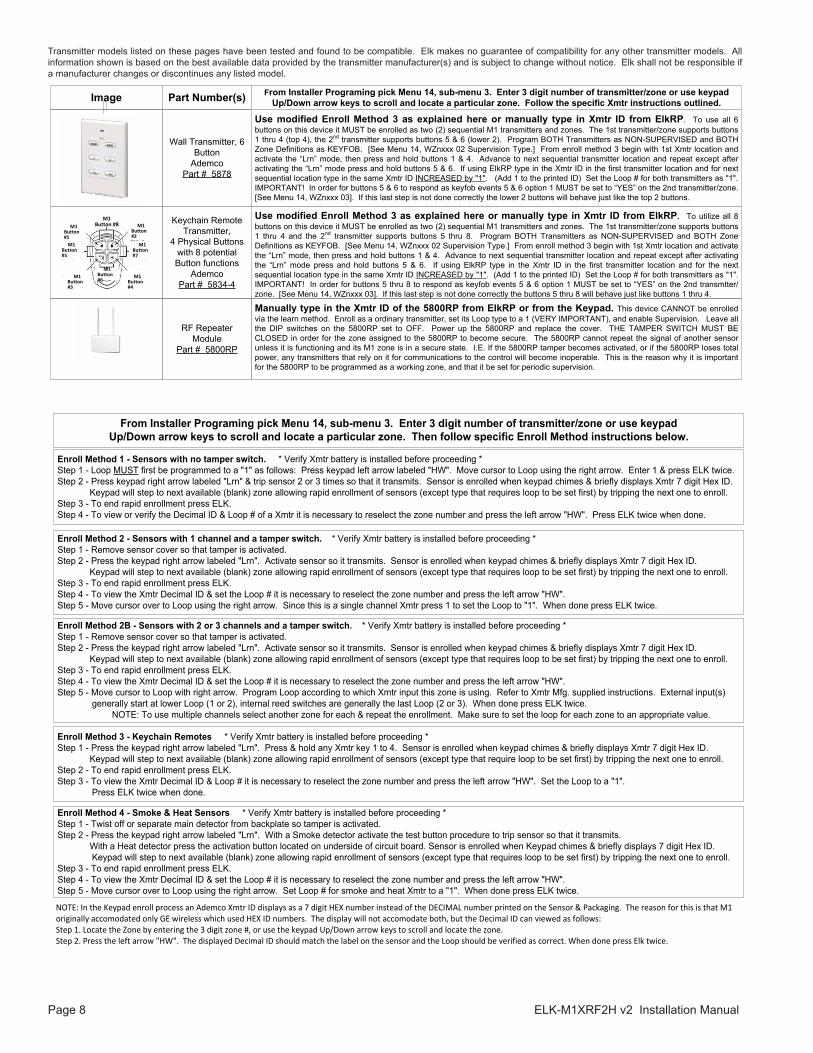
Page 8 ELK-M1XRF2H v2 Installation Manual
Transmitter models listed on these pages have been tested and found to be compatible. Elk makes no guarantee of compatibility for any other transmitter models. All information shown is based on the best available data provided by the transmitter manufacturer(s) and is subject to change without notice. Elk shall not be responsible if a manufacturer changes or discontinues any listed model.
Part Number(s)Image
Wall Transmitter, 6 Button
Ademco Part # 5878
Use modified Enroll Method 3 as explained here or manually type in Xmtr ID from ElkRP. To use all 6 buttons on this device it MUST be enrolled as two (2) sequential M1 transmitters and zones. The 1st transmitter/zone supports buttons 1 thru 4 (top 4), the 2nd transmitter supports buttons 5 & 6 (lower 2). Program BOTH Transmitters as NON-SUPERVISED and BOTH Zone Definitions as KEYFOB. [See Menu 14, WZnxxx 02 Supervision Type.] From enroll method 3 begin with 1st Xmtr location and activate the “Lrn” mode, then press and hold buttons 1 & 4. Advance to next sequential transmitter location and repeat except after activating the “Lrn” mode press and hold buttons 5 & 6. If using ElkRP type in the Xmtr ID in the first transmitter location and for next sequential location type in the same Xmtr ID INCREASED by "1". (Add 1 to the printed ID) Set the Loop # for both transmitters as "1". IMPORTANT! In order for buttons 5 & 6 to respond as keyfob events 5 & 6 option 1 MUST be set to “YES” on the 2nd transmitter/zone. [See Menu 14, WZnxxx 03]. If this last step is not done correctly the lower 2 buttons will behave just like the top 2 buttons.
From Installer Programing pick Menu 14, sub-menu 3. Enter 3 digit number of transmitter/zone or use keypad Up/Down arrow keys to scroll and locate a particular zone. Follow the specific Xmtr instructions outlined.
Keychain Remote Transmitter,
4 Physical Buttons with 8 potential Button functions
Ademco Part # 5834-4
Use modified Enroll Method 3 as explained here or manually type in Xmtr ID from ElkRP. To utilize all 8 buttons on this device it MUST be enrolled as two (2) sequential M1 transmitters and zones. The 1st transmitter/zone supports buttons 1 thru 4 and the 2nd transmitter supports buttons 5 thru 8. Program BOTH Transmitters as NON-SUPERVISED and BOTH Zone Definitions as KEYFOB. [See Menu 14, WZnxxx 02 Supervision Type.] From enroll method 3 begin with 1st Xmtr location and activate the “Lrn” mode, then press and hold buttons 1 & 4. Advance to next sequential transmitter location and repeat except after activating the “Lrn” mode press and hold buttons 5 & 6. If using ElkRP type in the Xmtr ID in the first transmitter location and for the next sequential location type in the same Xmtr ID INCREASED by "1". (Add 1 to the printed ID) Set the Loop # for both transmitters as "1". IMPORTANT! In order for buttons 5 thru 8 to respond as keyfob events 5 & 6 option 1 MUST be set to “YES” on the 2nd transmtter/zone. [See Menu 14, WZnxxx 03]. If this last step is not done correctly the buttons 5 thru 8 will behave just like buttons 1 thru 4.
M1 Button #8
M1 Button #7
M1 Button #5
M1 Button #6
M1 Button #2
M1 Button #1
M1 Button #3
M1 Button #4
Manually type in the Xmtr ID of the 5800RP from ElkRP or from the Keypad. This device CANNOT be enrolled via the learn method. Enroll as a ordinary transmitter, set its Loop type to a 1 (VERY IMPORTANT), and enable Supervision. Leave all the DIP switches on the 5800RP set to OFF. Power up the 5800RP and replace the cover. THE TAMPER SWITCH MUST BE CLOSED in order for the zone assigned to the 5800RP to become secure. The 5800RP cannot repeat the signal of another sensor unless it is functioning and its M1 zone is in a secure state. I.E. If the 5800RP tamper becomes activated, or if the 5800RP loses total power, any transmitters that rely on it for communications to the control will become inoperable. This is the reason why it is important for the 5800RP to be programmed as a working zone, and that it be set for periodic supervision.
RF Repeater Module
Part # 5800RP
Enroll Method 1 - Sensors with no tamper switch. * Verify Xmtr battery is installed before proceeding * Step 1 - Loop MUST first be programmed to a "1" as follows: Press keypad left arrow labeled "HW". Move cursor to Loop using the right arrow. Enter 1 & press ELK twice.Step 2 - Press keypad right arrow labeled "Lrn" & trip sensor 2 or 3 times so that it transmits. Sensor is enrolled when keypad chimes & briefly displays Xmtr 7 digit Hex ID. Keypad will step to next available (blank) zone allowing rapid enrollment of sensors (except type that requires loop to be set first) by tripping the next one to enroll. Step 3 - To end rapid enrollment press ELK.Step 4 - To view or verify the Decimal ID & Loop # of a Xmtr it is necessary to reselect the zone number and press the left arrow "HW". Press ELK twice when done.
Enroll Method 3 - Keychain Remotes * Verify Xmtr battery is installed before proceeding * Step 1 - Press the keypad right arrow labeled "Lrn". Press & hold any Xmtr key 1 to 4. Sensor is enrolled when keypad chimes & briefly displays Xmtr 7 digit Hex ID. Keypad will step to next available (blank) zone allowing rapid enrollment of sensors (except type that require loop to be set first) by tripping the next one to enroll.Step 2 - To end rapid enrollment press ELK.Step 3 - To view the Xmtr Decimal ID & Loop # it is necessary to reselect the zone number and press the left arrow "HW". Set the Loop to a "1".
Press ELK twice when done.
Enroll Method 2 - Sensors with 1 channel and a tamper switch. * Verify Xmtr battery is installed before proceeding * Step 1 - Remove sensor cover so that tamper is activated.Step 2 - Press the keypad right arrow labeled "Lrn". Activate sensor so it transmits. Sensor is enrolled when keypad chimes & briefly displays Xmtr 7 digit Hex ID. Keypad will step to next available (blank) zone allowing rapid enrollment of sensors (except type that requires loop to be set first) by tripping the next one to enroll.Step 3 - To end rapid enrollment press ELK.Step 4 - To view the Xmtr Decimal ID & set the Loop # it is necessary to reselect the zone number and press the left arrow "HW". Step 5 - Move cursor over to Loop using the right arrow. Since this is a single channel Xmtr press 1 to set the Loop to "1". When done press ELK twice.
Enroll Method 4 - Smoke & Heat Sensors * Verify Xmtr battery is installed before proceeding * Step 1 - Twist off or separate main detector from backplate so tamper is activated. Step 2 - Press the keypad right arrow labeled "Lrn". With a Smoke detector activate the test button procedure to trip sensor so that it transmits. With a Heat detector press the activation button located on underside of circuit board. Sensor is enrolled when Keypad chimes & briefly displays 7 digit Hex ID.
Keypad will step to next available (blank) zone allowing rapid enrollment of sensors (except type that requires loop to be set first) by tripping the next one to enroll.Step 3 - To end rapid enrollment press ELK.Step 4 - To view the Xmtr Decimal ID & set the Loop # it is necessary to reselect the zone number and press the left arrow "HW". Step 5 - Move cursor over to Loop using the right arrow. Set Loop # for smoke and heat Xmtr to a "1". When done press ELK twice.
Enroll Method 2B - Sensors with 2 or 3 channels and a tamper switch. * Verify Xmtr battery is installed before proceeding * Step 1 - Remove sensor cover so that tamper is activated.Step 2 - Press the keypad right arrow labeled "Lrn". Activate sensor so it transmits. Sensor is enrolled when keypad chimes & briefly displays Xmtr 7 digit Hex ID. Keypad will step to next available (blank) zone allowing rapid enrollment of sensors (except type that requires loop to be set first) by tripping the next one to enroll.Step 3 - To end rapid enrollment press ELK.Step 4 - To view the Xmtr Decimal ID & set the Loop # it is necessary to reselect the zone number and press the left arrow "HW". Step 5 - Move cursor to Loop with right arrow. Program Loop according to which Xmtr input this zone is using. Refer to Xmtr Mfg. supplied instructions. External input(s)
generally start at lower Loop (1 or 2), internal reed switches are generally the last Loop (2 or 3). When done press ELK twice. NOTE: To use multiple channels select another zone for each & repeat the enrollment. Make sure to set the loop for each zone to an appropriate value.
NOTE: In the Keypad enroll process an Ademco Xmtr ID displays as a 7 digit HEX number instead of the DECIMAL number printed on the Sensor & Packaging. The reason for this is that M1 originally accomodated only GE wireless which used HEX ID numbers. The display will not accomodate both, but the Decimal ID can viewed as follows: Step 1. Locate the Zone by entering the 3 digit zone #, or use the keypad Up/Down arrow keys to scroll and locate the zone.Step 2. Press the left arrow "HW". The displayed Decimal ID should match the label on the sensor and the Loop should be verified as correct. When done press Elk twice.
From Installer Programing pick Menu 14, sub-menu 3. Enter 3 digit number of transmitter/zone or use keypad Up/Down arrow keys to scroll and locate a particular zone. Then follow specific Enroll Method instructions below.

ELK-M1XRF2H v2 Installation Manual Page 9
This page intentionally left blank.
Page 10 ELK-M1XRF2H v2 Installation Manual
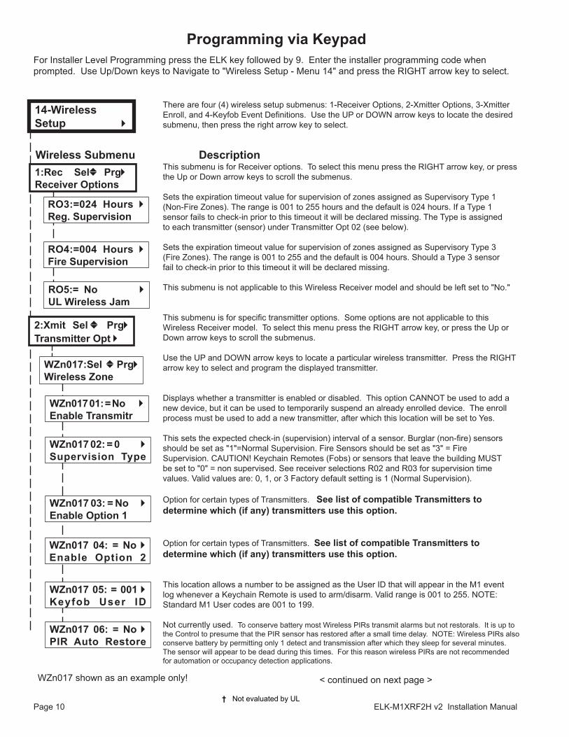
Wireless Submenu DescriptionThis submenu is for Receiver options. To select this menu press the RIGHT arrow key, or press the Up or Down arrow keys to scroll the submenus.
Sets the expiration timeout value for supervision of zones assigned as Supervisory Type 1(Non-Fire Zones). The range is 001 to 255 hours and the default is 024 hours. If a Type 1sensor fails to check-in prior to this timeout it will be declared missing. The Type is assignedto each transmitter (sensor) under Transmitter Opt 02 (see below).
Sets the expiration timeout value for supervision of zones assigned as Supervisory Type 3(Fire Zones). The range is 001 to 255 and the default is 004 hours. Should a Type 3 sensorfail to check-in prior to this timeout it will be declared missing.
This submenu is not applicable to this Wireless Receiver model and should be left set to "No."
This submenu is for specific transmitter options. Some options are not applicable to this Wireless Receiver model. To select this menu press the RIGHT arrow key, or press the Up or Down arrow keys to scroll the submenus.
Use the UP and DOWN arrow keys to locate a particular wireless transmitter. Press the RIGHT arrow key to select and program the displayed transmitter.
Displays whether a transmitter is enabled or disabled. This option CANNOT be used to add a new device, but it can be used to temporarily suspend an already enrolled device. The enroll process must be used to add a new transmitter, after which this location will be set to Yes. This sets the expected check-in (supervision) interval of a sensor. Burglar (non-fire) sensorsshould be set as "1"=Normal Supervision. Fire Sensors should be set as "3" = FireSupervision. CAUTION! Keychain Remotes (Fobs) or sensors that leave the building MUSTbe set to "0" = non supervised. See receiver selections R02 and R03 for supervision timevalues. Valid values are: 0, 1, or 3 Factory default setting is 1 (Normal Supervision).
Option for certain types of Transmitters. See list of compatible Transmitters to determine which (if any) transmitters use this option.
Option for certain types of Transmitters. See list of compatible Transmitters to determine which (if any) transmitters use this option.
This location allows a number to be assigned as the User ID that will appear in the M1 eventlog whenever a Keychain Remote is used to arm/disarm. Valid range is 001 to 255. NOTE:Standard M1 User codes are 001 to 199.
Not currently used. To conserve battery most Wireless PIRs transmit alarms but not restorals. It is up to the Control to presume that the PIR sensor has restored after a small time delay. NOTE: Wireless PIRs also conserve battery by permitting only 1 detect and transmission after which they sleep for several minutes. The sensor will appear to be dead during this times. For this reason wireless PIRs are not recommended for automation or occupancy detection applications.
There are four (4) wireless setup submenus: 1-Receiver Options, 2-Xmitter Options, 3-Xmitter Enroll, and 4-Keyfob Event Definitions. Use the UP or DOWN arrow keys to locate the desired submenu, then press the right arrow key to select.
† Not evaluated by UL
For Installer Level Programming press the ELK key followed by 9. Enter the installer programming code when prompted. Use Up/Down keys to Navigate to "Wireless Setup - Menu 14" and press the RIGHT arrow key to select.
Programming via Keypad
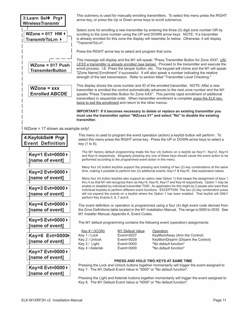
< continued on next page >WZn017 shown as an example only!
1:Rec Selb PrgrReceiver Options
14-WirelessSetup r
RO3:=024 Hours rReg. Supervision
RO4:=004 Hours rFire Supervision
2:Xmit Sel b PrgrTransmitter Opt r
WZn017 04: = No r Enable Option 2
WZn017 01: = No rEnable Transmitr
WZn017 02: = 0 r Supervision Type
WZn017 03: = No rEnable Option 1
WZn017:Sel bPrgrWireless Zone
WZn017 05: = 001 r Keyfob User ID
WZn017 06: = No r PIR Auto Restore
RO5:= No rUL Wireless Jam
ELK-M1XRF2H v2 Installation Manual Page 11
Select zone for enrolling a new transmitter by entering the three (3) digit zone number OR by scrolling to the zone number using the UP and DOWN arrow keys. NOTE: If a transmitter is already enrolled for this zone the display will resemble 3c below. Otherwise, it will display "TransmitrToLrn".
Press the RIGHT arrow key to select and program that zone.
This message will display and the M1 will speak: "Press Transmitter Button for Zone XXX", UN-LESS a transmitter is already enrolled (see below). Proceed to the transmitter and execute the enroll process. I.E. Press the tamper button, etc. The keypad will chime and the M1 will speak: "[Zone Name] Enrollment" if successful. It will also speak a number indicating the relative strength of the last transmission. Refer to section titled "Transmitter Level Checking."
This display shows the zone number and ID of the enrolled transmitter. NOTE: After a new transmitter is enrolled the control automatically advances to the next zone number and the M1 speaks "Press Transmitter Button for Zone XXX". This permits rapid enrollment of additional transmitters in sequential order. When transmitter enrollment is complete press the ELK key twice to exit the enrollment and return to the other menus.
IMPORTANT! If it becomes necessary to delete or replace an existing transmitter you must use the transmitter option "WZnxxx 01" and select "No" to disable the existing transmitter.
This submenu is used for manually enrolling transmitters. To select this menu press the RIGHT arrow key, or press the Up or Down arrow keys to scroll submenus.
This menu is used to program the event operation (action) a keyfob button will perform. To select this menu press the RIGHT arrow key. Press the UP or DOWN arrow keys to select a key (1 to 8).
The M1 factory default programming treats the four (4) buttons on a keyfob as Key=1, Key=2, Key=3 and Key=4 respectively. Singularly pressing any one of these keys should cause the event action to be performed according to the programmed event action in this menu.
Many four (4) button keyfobs support the pressing and holding of two (2) key combinations at the same time, making it possible to perform two (2) additional events, Key=7 & Key=8. See explanation below.
Many four (4) button keyfobs also support an option (see Option 1) that swaps the assignment of keys 1 thru 4 so that M1 will recognize them as Key=5, Key=6, Key=7 and Key=8 respectively. Option 1 may be enable or disabled by individual transmitter TXID. An application for this might be 2 people who want their individual keyfobs to perform different event functions. EXCEPTION: The two (2) key combination press will not expand the events on a keyfob where the Option 1 has been enabled. That keyfob will ONLY perform Key Events 5, 6, 7 and 8.
The event definition or operation is programmed using a four (4) digit event code derived from the Zone Definitions table located in the M1 Installation Manual. The range is 0000 to 0030 See M1 Installer Manual, Appendix A, Event Codes.
The M1 default programming contains the following event (operation) assignments: Key # / (ICON) M1 Default Value OperationKey 1 / Lock Event=0027 KeyMomAway (Arm the Control)Key 2 / Unlock Event=0029 KeyMomDisarm (Disarm the Control)Key 3 / Light Event=0000 "No default function"Key 4 / Asterisk Event=0000 "No default function"
PRESS AND HOLD TWO KEYS AT SAME TIMEPressing the Lock and Unlock buttons together momentarily will trigger the event assigned to Key 7. The M1 Default Event Value is "0000" or "No default function".
Pressing the Light and Asterisk buttons together momentarily will trigger the event assigned to Key 8. The M1 Default Event Value is "0000" or "No default function".
WZone = 17 shown as example only!
WZone = 017 Push TransmiterButton
WZone = 017 HW lTransmitrToLrn r
3:Learn Selb Prg rWirelessTransmtr
WZone = xxx Enrolled ABCDE
Key=1 Evt=0000 r[name of event]
Key=2 Evt=0000 r[name of event]
Key=3 Evt=0000 r[name of event]
Key=4 Evt=0000 r[name of event]
Key=5 Evt=0000 r[name of event]
Key=6 Evt=0000r[name of event]
Key=7 Evt=0000 r[name of event]
Key=8 Evt=0000 r[name of event]
4:KeyfobSelb Prg rEvent Definition
Page 12 ELK-M1XRF2H v2 Installation Manual
H or RRF
Total Wireless Zones(max.)
16 H or RRF H or RRF H or RRF H or RRF H or RRF H or RRF H or RRF H or RRF H or RRF H or RRF
Data BusAddr 12
Zn 177-192
* * H or RRF H or RRF H or RRF H or RRF H or RRF H or RRF H or RRFH or RRF H or RRF H or RRF H or RRF H or RRF H or RRF H or RRFH or RRF H or RRF H or RRF H or RRF H or RRF H or RRF H or RRF
* * * ** * H or RRF H or RRF H or RRF H or RRF H or RRF H or RRF* ** * * * * ** * H or RRF H or RRF H or RRF H or RRF H or RRF
* * * ** * * * * ** * H or RRF H or RRF H or RRF H or RRF* ** * * * * * * ** * H or RRF H or RRF H or RRF
* * * * * * * * * * * * H or RRF H or RRF* ** ** *
H or RRF
H or RRFH or RRF
H or RRFH or RRF
H or RRFH or RRF
H or RRF
Data BusAddr 13
Zn 193-208
Data BusAddr 9
Zn 129-144
Data BusAddr 11
Zn 161-176
Data BusAddr 8
Zn 113-128
Data BusAddr 6
Zn 81 - 96
Data BusAddr 3
Zn 33 - 48
Data BusAddr 4
Zn 49 - 64
Data BusAddr 7
Zn 97 - 112
Data BusAddr 5
Zn 65 - 80
Data BusAddr 10
Zn 145-160
3248648096112128144
* * * *H or RRF
* * * * * *
H or RRFH or RRF
* *M1XRF
Starting Zn ID #17Data bus Addr 2
Zn 17-32
H or RRF
Total Wireless Zones(max.)
16 H or RRF H or RRF H or RRF H or RRF H or RRF H or RRF H or RRF H or RRFH or RRF H or RRF
Data BusAddr 12
Zn 177-192
* * H or RRF H or RRF H or RRF H or RRFH or RRF H or RRF H or RRFH or RRF H or RRF H or RRF H or RRF H or RRFH or RRF H or RRFH or RRF H or RRF H or RRF H or RRF H or RRFH or RRF H or RRF
* * * ** * H or RRF H or RRF H or RRF H or RRFH or RRF H or RRF* ** * * * * ** * H or RRF H or RRF H or RRFH or RRF H or RRF
* * * ** * * * * ** * H or RRF H or RRFH or RRF H or RRF* ** * * * * * * ** * H or RRFH or RRF H or RRF* *
H or RRF
H or RRFH or RRF
H or RRFH or RRF
H or RRFH or RRF
Data BusAddr 13
Zn 193-208
Data BusAddr 9
Zn 129-144
Data BusAddr 11
Zn 161-176
Data BusAddr 8
Zn 113-128
Data BusAddr 6
Zn 81 - 96
Data BusAddr 4
Zn 49 - 64
Data BusAddr 7
Zn 97 - 112
Data BusAddr 5
Zn 65 - 80
Data BusAddr 10
Zn 145-160
3248648096112128
* * * *H or RRF
* * * * * *
H or RRFH or RRF
* *M1XRF
Data BusAddr 2
Zn 17 -32
Starting Zn ID #33Data bus Addr 3
Zn 33-48
H or RRF
Total Wireless Zones(max.)
16 H or RRF H or RRF H or RRF H or RRF H or RRF H or RRF H or RRF H or RRFH or RRF H or RRF
Data BusAddr 12
Zn 177-192
* * H or RRF H or RRF H or RRF H or RRFH or RRF H or RRF H or RRFH or RRF H or RRF H or RRF H or RRF H or RRFH or RRF H or RRFH or RRF H or RRF H or RRF H or RRF H or RRFH or RRF H or RRF
* * * ** * H or RRF H or RRF H or RRF H or RRFH or RRF H or RRF* ** * * * * ** * H or RRF H or RRF H or RRFH or RRF H or RRF
* * * ** * * * * ** * H or RRF H or RRFH or RRF H or RRF
H or RRF
H or RRFH or RRF
H or RRFH or RRF
H or RRF
Data BusAddr 13
Zn 193-208
Data BusAddr 9
Zn 129-144
Data BusAddr 11
Zn 161-176
Data BusAddr 8
Zn 113-128
Data BusAddr 6
Zn 81 - 96
Data BusAddr 7
Zn 97 - 112
Data BusAddr 5
Zn 65 - 80
Data BusAddr 10
Zn 145-160
3248648096112
* * * *H or RRF
* * * * * *
H or RRFH or RRF
* *
Data BusAddr 2
Zn 17 -32
Data BusAddr 3
Zn 33 - 48
Starting Zn ID #49Data Bus
Addr 4Zn 49 - 64
M1XRF
Cells marked " * * " indicate a Reserved Address which can only be used for wireless zones. Cells marked " RRF " indicate bus addresses where ONLY a redundant Wireless Receiver can be installed. Cells marked " H or RRF " indicate bus addresses where either a Hardwired Expander OR a redundant Wireles Receiver can be installed.
These tables are intended to help visualize how Wireless Receiver Zone Expanders utilize Data Bus Addresses compared to Hardwired Zone Expanders. Observe and follow the Data Bus Addresses and their starting & ending Zone numbers to attain the total and best mix of wireless and hardwired zones. The left column shows the maximum total wireless zones that may be attained based on the data bus addresses consumed.
1. Each table has a bolded column showing the staring (1st) wireless zone ID at each associated data bus address.
NOTE: The total (max.) number of wireless zones is decreased by 16 zones for any hardwired expanders installed or enrolled in the range of zones 17 through 160. This is because only zones 17 through 160 can be used for wireless.
2. Decide how many "total" wireless zones might be required for the job. This narrows down which table to concentrate on.
3. Consider existing or future Hardwired Zone Expanders. The wireless starting zone ID is critical if you want all wireless zones to besequential with no hardwired zones interspersed between them. The following are some suggested guidelines:
- If a job needs 16 hardwired zones or less with no plans for expansion then start the first wireless at zone 17 (associated with data busaddress 2). This leaves the most room for future wireless expansion all the way up to zone 160. On the contrary if a job needs a lot of hardwired zones and very few wireless zones the Wireless Receiver could be assigned as high as Address 10.
4. Select any table below and start in the left column by choosing the total number of wireless zones required. Follow the row acrossto the bold column displaying the starting zone ID and associated data bus address where you wish to begin.
- Cells marked with "* *" indicate bus addresses "reserved" exclusively for wireless zones. However, any of these addresses may also be used for a redundant Wireless Receiver. Redundant Receivers provide additional range and coverage for extremely large or difficult buildings.
See Appendix C regarding Redundant Receivers. - Cells marked "RRF" indicate bus addresses where ONLY a redundant Wireless Receiver can be installed. - Cells marked "H or RRF" indicate bus addresses where either a Hardwired Expander OR a redundant Wireless Receiver can be installed.
NOTE: A Wireless Receiver installed for redundancy does not increase the number of wireless zones, it only increases range and/or coverage.
No RF Zones Here
No RF Zones Here
No RF Zones Here
Appendix A - Data Bus Selection Tables
ELK-M1XRF2H v2 Installation Manual Page 13
H or RRF
Total Wireless Zones(max.)
16 H or RRF H or RRF H or RRF H or RRF H or RRFH or RRFH or RRFH or RRFH or RRF H or RRF
Data BusAddr 12
Zn 177-192
* * H or RRF H or RRFH or RRFH or RRFH or RRF H or RRF H or RRFH or RRF H or RRFH or RRFH or RRFH or RRFH or RRF H or RRFH or RRF H or RRFH or RRFH or RRFH or RRFH or RRF H or RRF
H or RRF
H or RRFH or RRF
Data BusAddr 13
Zn 193-208
Data BusAddr 9
Zn 129-144
Data BusAddr 11
Zn 161-176
Data BusAddr 8
Zn 113-128
Data BusAddr 10
Zn 145-160
324864
* * * *H or RRF
* * * * * *
H or RRFH or RRFM1XRF
Data BusAddr 2
Zn 17 -32
Data BusAddr 3
Zn 33 - 48
Data BusAddr 4
Zn 49 - 64
Data BusAddr 5
Zn 65 - 80
Data BusAddr 6
Zn 81 - 96
Starting Zn ID #97Data Bus
Addr 7Zn 97 - 112
H or RRF
Total Wireless Zones(max.)
16 H or RRF H or RRF H or RRF H or RRFH or RRFH or RRFH or RRFH or RRFH or RRF H or RRF
Data BusAddr 12
Zn 177-192
* * H or RRFH or RRFH or RRFH or RRFH or RRF H or RRF H or RRFH or RRFH or RRFH or RRFH or RRFH or RRFH or RRF H or RRF
H or RRF
H or RRF
Data BusAddr 13
Zn 193-208
Data BusAddr 9
Zn 129-144
Data BusAddr 11
Zn 161-176
Data BusAddr 10
Zn 145-160
3248 * * * *
H or RRF H or RRFH or RRF
M1XRF
Data BusAddr 2
Zn 17 -32
Data BusAddr 3
Zn 33 - 48
Data BusAddr 4
Zn 49 - 64
Data BusAddr 5
Zn 65 - 80
Data BusAddr 6
Zn 81 - 96
Data BusAddr 7
Zn 97 - 112
Starting Zn ID #113Data Bus
Addr 8Zn 113-128
H or RRF
Total Wireless Zones(max.)
16 H or RRF H or RRF H or RRFH or RRFH or RRFH or RRFH or RRFH or RRFH or RRF H or RRF
Data BusAddr 12
Zn 177-192
* *H or RRFH or RRFH or RRFH or RRFH or RRF H or RRF H or RRFH or RRF
Data BusAddr 13
Zn 193-208
Data BusAddr 11
Zn 161-176
Data BusAddr 10
Zn 145-160
32 H or RRF H or RRFM1XRF
Data BusAddr 2
Zn 17 -32
Data BusAddr 3
Zn 33 - 48
Data BusAddr 4
Zn 49 - 64
Data BusAddr 5
Zn 65 - 80
Data BusAddr 6
Zn 81 - 96
Data BusAddr 7
Zn 97 - 112
Data BusAddr 8
Zn 113-128
Starting Zn ID #129Data Bus
Addr 9Zn 129-144
Total Wireless Zones(max.)
16 H or RRF H or RRFH or RRFH or RRFH or RRFH or RRFH or RRFH or RRFH or RRF H or RRF
Data BusAddr 12
Zn 177-192
H or RRF
Data BusAddr 13
Zn 193-208
Data BusAddr 11
Zn 161-176
M1XRF
Data BusAddr 2
Zn 17 -32
Data BusAddr 3
Zn 33 - 48
Data BusAddr 4
Zn 49 - 64
Data BusAddr 5
Zn 65 - 80
Data BusAddr 6
Zn 81 - 96
Data BusAddr 7
Zn 97 - 112
Data BusAddr 8
Zn 113-128
Data BusAddr 9
Zn 129-144
Starting Zn ID #145Data BusAddr 10
Zn 145-160
H or RRF
Total Wireless Zones(max.)
16 H or RRF H or RRF H or RRF H or RRF H or RRF H or RRFH or RRFH or RRFH or RRF H or RRF
Data BusAddr 12
Zn 177-192
* * H or RRF H or RRF H or RRFH or RRFH or RRF H or RRF H or RRFH or RRF H or RRF H or RRFH or RRFH or RRFH or RRF H or RRFH or RRF H or RRF H or RRFH or RRFH or RRFH or RRF H or RRF
* * * ** * H or RRF H or RRFH or RRFH or RRFH or RRF H or RRF
H or RRF
H or RRFH or RRF
H or RRF
Data BusAddr 13
Zn 193-208
Data BusAddr 9
Zn 129-144
Data BusAddr 11
Zn 161-176
Data BusAddr 8
Zn 113-128
Data BusAddr 7
Zn 97 - 112
Data BusAddr 10
Zn 145-160
32486480
* * * *H or RRF
* * * * * *
H or RRFH or RRF
* *
M1XRF
Data BusAddr 2
Zn 17 -32
Data BusAddr 3
Zn 33 - 48
Data BusAddr 4
Zn 49 - 64
Data BusAddr 5
Zn 65 - 80
Starting Zn ID #81Data Bus
Addr 6Zn 81 - 96
Cells marked " * * " indicate a Reserved Address which can only be used for wireless zones. Cells marked " RRF " indicate bus addresses where ONLY a redundant Wireless Receiver can be installed. Cells marked " H or RRF " indicate bus addresses where either a Hardwired Expander OR a redundant Wireless Receiver can be installed.
H or RRF
Total Wireless Zones(max.)
16 H or RRF H or RRF H or RRF H or RRF H or RRF H or RRF H or RRFH or RRFH or RRF H or RRF
Data BusAddr 12
Zn 177-192
* * H or RRF H or RRF H or RRFH or RRFH or RRF H or RRF H or RRFH or RRF H or RRF H or RRF H or RRFH or RRFH or RRF H or RRFH or RRF H or RRF H or RRF H or RRFH or RRFH or RRF H or RRF
* * * ** * H or RRF H or RRF H or RRFH or RRFH or RRF H or RRF* ** * * * * ** * H or RRF H or RRFH or RRFH or RRF H or RRF
H or RRF
H or RRFH or RRF
H or RRFH or RRF
Data BusAddr 13
Zn 193-208
Data BusAddr 9
Zn 129-144
Data BusAddr 11
Zn 161-176
Data BusAddr 8
Zn 113-128
Data BusAddr 6
Zn 81 - 96
Data BusAddr 7
Zn 97 - 112
Data BusAddr 10
Zn 145-160
3248648096
* * * *H or RRF
* * * * * *
H or RRFH or RRF
* *
M1XRF
Data BusAddr 2
Zn 17 -32
Data BusAddr 3
Zn 33 - 48
Data BusAddr 4
Zn 49 - 64
Starting Zn ID #65Data Bus
Addr 5Zn 65 - 80
No RF Zones Here
No RF Zones Here
No RF Zones Here
No RF Zones Here
No RF Zones Here
No RF Zones Here
Appendix A - Data Bus Selection Tables (cont'd)
Page 14 ELK-M1XRF2H v2 Installation Manual
Example A
All 208 Zones as Hardwired
Zones1‐16
Inputs onMain Panel
Zones17‐32
Hardwired Expander
Zones33‐48
Zones49‐64
Zones65‐80
Zones81‐96
Zones97‐112
Zones113‐128
Zones129‐144
Zones145‐160
Zones161‐176
Zones177‐192
Zones193‐208
Example B16 Hardwired Zones144 Wireless Zones
NOHardwired Expanders on these addresses
Example C48 Hardwired Zones112 Wireless Zones
PLUS 2 Redundant Receivers
Bus Addr x
Bus Addr 2
Hardwired Expander
Bus Addr 3
Hardwired Expander
Bus Addr 4
Hardwired Expander
Bus Addr 5
Hardwired Expander
Bus Addr 6
Hardwired Expander
Bus Addr 7
Hardwired Expander
Bus Addr 8
Hardwired Expander
Bus Addr 9
Hardwired Expander
Bus Addr 10
Hardwired Expander
Bus Addr 11
Hardwired Expander
Bus Addr 12
Hardwired Exp. or
Keypad Zns
Bus Addr 13
Zones1‐16
Inputs onMain Panel
Zones17‐32
Zones33‐48
Zones49‐64
Zones65‐80
Zones81‐96
Zones97‐112
Zones113‐128
Zones129‐144
Zones145‐160
Zones161‐176
Zones177‐192
Zones193‐208
Bus Addr x
Bus Addr 2
Bus Addr 3
Bus Addr 4
Bus Addr 5
Bus Addr 6
Bus Addr 7
Bus Addr 8
Bus Addr 9
Bus Addr 10
Hardwired Exp. or
Keypad Zns
Bus Addr 13
Wireless Receiver
Hardwired Expander or Redundant
Wireless Rec. *
NOHardwired Expanders on these addresses
Zones1‐16
Inputs onMain Panel
Zones17‐32
Zones33‐48
Zones49‐64
Zones65‐80
Zones81‐96
Zones97‐112
Zones113‐128
Zones129‐144
Zones145‐160
Zones161‐176
Zones177‐192
Zones193‐208
Bus Addr x
Bus Addr 2
Bus Addr 3
Bus Addr 4
Bus Addr 5
Bus Addr 6
Bus Addr 7
Bus Addr 8
Bus Addr 9
Bus Addr 10
Hardwired Exp. or
Keypad Zns
Bus Addr 13
Wireless Receiver
Hardwired Expander
Hardwired Expander
Bus Addr 14
Bus Addr 15
N/A
N/A
N/A
N/A
Maxim
um of 112 W
ireless Zones
< ‐‐‐‐‐‐‐ Redundant Wireless Receiver *
< ‐‐‐‐‐‐‐ Redundant Wireless Receiver *
Maxim
um of 144 W
ireless Zones
Hardwired Expander or Redundant
Wireless Rec. *
Bus Addr 11
Bus Addr 12
Bus Addr 11
Bus Addr 12
Bus Addr 14
Bus Addr 15
N/A
N/A
N/A
N/A
Bus Addr 14
Bus Addr 15
N/A
N/A
N/A
N/A
Appendix B - Examples of Zone Configurations
ELK-M1XRF2H v2 Installation Manual Page 15
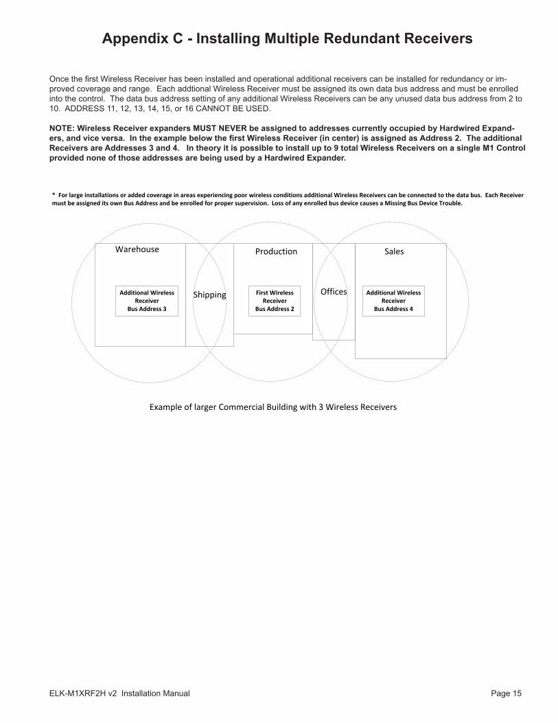
Once the first Wireless Receiver has been installed and operational additional receivers can be installed for redundancy or im-proved coverage and range. Each addtional Wireless Receiver must be assigned its own data bus address and must be enrolled into the control. The data bus address setting of any additional Wireless Receivers can be any unused data bus address from 2 to 10. ADDRESS 11, 12, 13, 14, 15, or 16 CANNOT BE USED.
NOTE: Wireless Receiver expanders MUST NEVER be assigned to addresses currently occupied by Hardwired Expand-ers, and vice versa. In the example below the first Wireless Receiver (in center) is assigned as Address 2. The additional Receivers are Addresses 3 and 4. In theory it is possible to install up to 9 total Wireless Receivers on a single M1 Control provided none of those addresses are being used by a Hardwired Expander.
* For large installations or added coverage in areas experiencing poor wireless conditions additional Wireless Receivers can be connected to the data bus. Each Receiver must be assigned its own Bus Address and be enrolled for proper supervision. Loss of any enrolled bus device causes a Missing Bus Device Trouble.
OfficesShipping First Wireless Receiver
Bus Address 2
Warehouse Production Sales
Example of larger Commercial Building with 3 Wireless Receivers
Additional Wireless Receiver
Bus Address 3
Additional Wireless Receiver
Bus Address 4
Appendix C - Installing Multiple Redundant Receivers

Page 16 ELK-M1XRF2H v2 Installation Manual
PO Box 1003266 US Hwy 70 WestHildebran, NC 28637
828-397-4200 828-397-4415 Faxhttp://www.elkproducts.com
Related Documents