Page 1 of 27 INSTALLATION INSTRUCTIONS WALL MOUNTED PACKAGE HEAT PUMPS MODELS W18H1 W24H1 W24H1D W30H1 W30H1D W36H1 W36H1D W42H1 W42H1D W48H1 W48H1D W60H1 W60H1D Manual: 2100-511F Supersedes: 2100-511E File: Volume III Tab 17 Date: 02-17-12 Bard Manufacturing Company, Inc. Bryan, Ohio 43506 Since 1914...Moving ahead just as planned.

Welcome message from author
This document is posted to help you gain knowledge. Please leave a comment to let me know what you think about it! Share it to your friends and learn new things together.
Transcript

Manual 2100-511FPage 1 of 27
INSTALLATION INSTRUCTIONS
WALL MOUNTEDPACKAGE HEAT PUMPS
MODELSW18H1W24H1 W24H1DW30H1 W30H1DW36H1 W36H1DW42H1 W42H1DW48H1 W48H1DW60H1 W60H1D
Manual: 2100-511FSupersedes: 2100-511EFile: Volume III Tab 17Date: 02-17-12
Bard Manufacturing Company, Inc.Bryan, Ohio 43506
Since 1914...Moving ahead just as planned.

Manual 2100-511FPage 2 of 27
Contents
FiguresFigure 1 Fresh Air Damper Assembly ................... 5Figure 2 Unit Dimensions ...................................... 7Figure 3A Mounting Instructions .............................. 8Figure 3B Mounting Instructions - W18, W24, W30, W36 .... 9Figure 3C Mounting Instructions - W42, W48, W60 .....10Figure 4 Electric Heat Clearance .........................11Figure 5 Wall Mounting Instructions .................... 12Figure 6 Wall Mounting Instructions .................... 12Figure 7 Common Wall Mounting Installations .... 13Figure 8 Defrost Control Board ........................... 18Figure 9 Fan Blade Setting ................................. 21
TablesTable 1 Troubleshooting .................................... 19Table 2 Fan Blade Dimension............................ 21Table 3A Cooling Pressure .................................. 22Table 3B Heating Pressure .................................. 22Table 4 Electrical Specifications W**H .............. 23Table 5 Recommended Airflow .......................... 24Table 6 Indoor Blower Performance .................. 24Tables 7 Maximum ESP Electric Heat Only ........ 25Table 8 Electric Heat ......................................... 25Table 9 Optional Accessories ........................... 26Table 10 Vent & Control Options ......................... 27
Getting Other Information and Publications 3
Wall Mount General InformationWall Mount Model Nomenclature ............................ 4Shipping Damage .................................................... 4General ................................................................ 4Duct Work ................................................................ 5Filters ................................................................ 5Fresh Air Intake ....................................................... 5Condensate Drain .................................................... 5
Installation InstructionsWall Mounting Information ....................................... 6Mounting the Unit .................................................... 6Clearances Required ............................................... 6Minimum Clearances ............................................... 6Wiring – Main Power ............................................. 14Wiring – Low Voltage Wiring ................................. 14
Start UpGeneral .............................................................. 15Topping Off System Charge................................... 15Safety Practices ..................................................... 15Important Installer Note ......................................... 16Wall Mounted Air Conditioner ................................ 16Three Phase Scroll Compressor ............................ 16Phase Monitor ....................................................... 16Condenser Fan Operation ..................................... 16Service Hints ......................................................... 16Sequence of Operation .......................................... 17Pressure Service Ports .......................................... 17Defrost Cycle ......................................................... 17
TroubleshootingSolid State Heat Pump Control .............................. 19Checking Temperature Sensor .............................. 20Fan Blade Setting Dimensions .............................. 21Removal of Fan Shroud ......................................... 21Refrigerant Charge ................................................ 21

Manual 2100-511FPage 3 of 27
GETTING OTHER INFORMATION AND PUBLICATIONS
These publications can help you install the airconditioner or heat pump. You can usually find these atyour local library or purchase them directly from thepublisher. Be sure to consult current edition of eachstandard.
National Electrical Code ...................... ANSI/NFPA 70
Standard for the Installation .............. ANSI/NFPA 90Aof Air Conditioning and Ventilating Systems
Standard for Warm Air ...................... ANSI/NFPA 90BHeating and Air Conditioning Systems
Load Calculation for ............................ ACCA Manual JResidential Winter and Summer Air Conditioning
Duct Design for Residential .............. ACCA Manual DWinter and Summer Air Conditioning and EquipmentSelection
FOR MORE INFORMATION, CONTACTTHESE PUBLISHERS:
ACCA Air Conditioning Contractors of America1712 New Hampshire Ave. N.W.Washington, DC 20009Telephone: (202) 483-9370Fax: (202) 234-4721
ANSI American National Standards Institute11 West Street, 13th FloorNew York, NY 10036Telephone: (212) 642-4900Fax: (212) 302-1286
ASHRAE American Society of Heating, Refrigerationand Air Conditioning Engineers, Inc.1791 Tullie Circle, N.E.Atlanta, GA 30329-2305Telephone: (404) 636-8400Fax: (404) 321-5478
NFPA National Fire Protection AssociationBatterymarch ParkP.O. Box 9101Quincy, MA 02269-9901Telephone: (800) 344-3555Fax: (617) 984-7057

Manual 2100-511FPage 4 of 27
WALL MOUNT GENERAL INFORMATION
HEAT PUMP WALL MOUNT MODEL NOMENCLATURE
W 42 H 1 – A 10 X X X X X A
NOTE: Vent options X, B and M are without exhaust capability. May require separate field supplied barometric relief in building.
SHIPPING DAMAGEUpon receipt of equipment, the carton should bechecked for external signs of shipping damage. Ifdamage is found, the receiving party must contact thelast carrier immediately, preferably in writing,requesting inspection by the carrier’s agent.
GENERALThe equipment covered in this manual is to be installedby trained, experienced service and installationtechnicians.
The refrigerant system is completely assembled andcharged. All internal wiring is complete.
The unit is designed for use with or without duct work.Flanges are provided for attaching the supply and returnducts.
These instructions explain the recommended method toinstall the air cooled self-contained unit and theelectrical wiring connections to the unit.
These instructions and any instructions packaged withany separate equipment required to make up the entireair conditioning system should be carefully read beforebeginning the installation. Note particularly “StartingProcedure” and any tags and/or labels attached to theequipment.
While these instructions are intended as a generalrecommended guide, they do not supersede any nationaland/or local codes in any way. Authorities havingjurisdiction should be consulted before the installation ismade. See Page 3 for information on codes andstandards.
Size of unit for a proposed installation should be basedon heat loss/gain calculation made according to methodsof Air Conditioning Contractors of America (ACCA).The air duct should be installed in accordance with theStandards of the National Fire Protection Associationfor the Installation of Air Conditioning and VentilatingSystems of Other Than Residence Type, NFPA No.90A, and Residence Type Warm Air Heating and AirConditioning Systems, NFPA No. 90B. Where localregulations are at a variance with instructions, installershould adhere to local codes.
KW 1
1 For 0 KW and circuit breakers (230/208 volt) or toggle disconnect (460V) applications, insert 0Z in the KW field of the model number.2 Insert “D” for dehumidification with hot gas reheat. Reference Form 7960-576 for complete details.
MODEL NUMBER CONTROL MODULES(See Spec. Sheet S3398)
VOLTS & PHASEA - 230/208/60/1B - 230/208/60/3C - 460/60/3
REVISIONS
VENTILATION OPTIONSX - Barometric Fresh Air Damper (Standard)B - Blank-off PlateM - Motorized Fresh Air DamperV - Commercial Ventilator - Motorized with ExhaustE - Economizer (Internal) - Fully Modulating with ExhaustR - Energy Recovery Ventilator - Motorized with Exhaust
(See Spec. Sheet S3398)
FILTER OPTIONSX - One Inch Throwaway (Standard)W - One Inch WashableP - Two Inch Pleated
COLOR OPTIONSX - Beige (Standard)1 - White4 - Buckeye Gray5 - Desert Brown8 - Dark Bronze
COIL OPTIONSX - Standard1 - Phenolic Coated Evaporator2 - Phenolic Coated Condenser3 - Phenolic Coated Evaporator
and Condenser
OUTLET OPTIONSX - Front (Standard)T - Top Outlet (W30H, W36H Only)
CAPACITY18 - 1½ Ton24 - 2 Ton30 - 2½ Ton36 - 3 Ton42 - 3½ Ton48 - 4 Ton60 - 5 Ton
H - Heat Pump
SPECIALTY PRODUCTS 2(Non-Standard)
Manual 2100-511FPage 5 of 27
DUCT WORKAll duct work, supply and return, must be properly sizedfor the design airflow requirement of the equipment. AirConditioning Contractors of America (ACCA) is anexcellent guide to proper sizing. All duct work or portionsthereof not in the conditioned space should be properlyinsulated in order to both conserve energy and preventcondensation or moisture damage.
Refer to Maximum ESP of operation Electric Heat Tables 7.
Design the duct work according to methods given by the AirConditioning Contractors of America (ACCA). When ductruns through unheated spaces, it should be insulated with aminimum of one inch of insulation. Use insulation with avapor barrier on the outside of the insulation. Flexible jointsshould be used to connect the duct work to the equipment inorder to keep the noise transmission to a minimum.
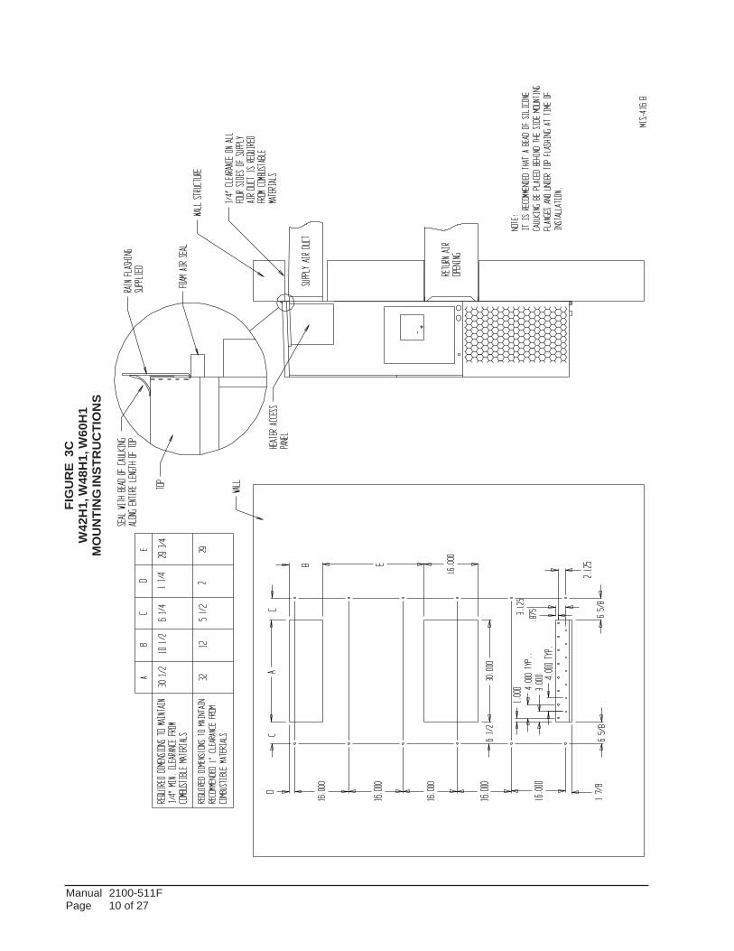
Models W18 & W24 are approved for zero inch clearanceto the supply duct. For model series W30, W36, W42, W48and W60 a 1/4 inch clearance to combustible material forthe first three feet of duct attached to the outlet air frame isrequired. See Wall Mounting Instructions and Figures 3 and4 for further details.
Ducts through the walls must be insulated and all jointstaped or sealed to prevent air or moisture entering the wallcavity.
Some installations may not require any return air duct. Ametallic return air grille is required with installations notrequiring a return air duct. The spacing between louvers onthe grille shall not be larger than 5/8 inch.
Any grille that meets with 5/8 inch louver criteria may beused. It is recommended that Bard Return Air Grille KitRG2 through RG5 or RFG2 through RFG5 be installedwhen no return duct is used. Contact distributor or factoryfor ordering information. If using a return air filter grille,filters must be of sufficient size to allow a maximumvelocity of 400 fpm.
NOTE: If no return air duct is used, applicable installationcodes may limit this cabinet to installation only in asingle story structure.
FILTERSA 1-inch throwaway filter is standard with each unit.The filter slides into position making it easy to service.This filter can be serviced from the outside by removingthe filter access panel. A 1-inch washable filter and 2-inch pleated filter are also available as optionalaccessories. The internal filter brackets are adjustableto accommodate the 2-inch filter by bending two (2)tabs down on each side of the filter support bracket.
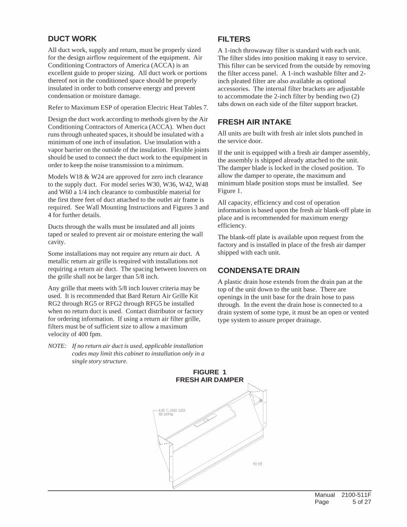
FRESH AIR INTAKEAll units are built with fresh air inlet slots punched inthe service door.
If the unit is equipped with a fresh air damper assembly,the assembly is shipped already attached to the unit.The damper blade is locked in the closed position. Toallow the damper to operate, the maximum andminimum blade position stops must be installed. SeeFigure 1.
All capacity, efficiency and cost of operationinformation is based upon the fresh air blank-off plate inplace and is recommended for maximum energyefficiency.
The blank-off plate is available upon request from thefactory and is installed in place of the fresh air dampershipped with each unit.
CONDENSATE DRAINA plastic drain hose extends from the drain pan at thetop of the unit down to the unit base. There areopenings in the unit base for the drain hose to passthrough. In the event the drain hose is connected to adrain system of some type, it must be an open or ventedtype system to assure proper drainage.
FIGURE 1FRESH AIR DAMPER

Manual 2100-511FPage 6 of 27
sseccAecivreSrofderiuqeRsecnaraelC
wolfriAresnednoCetauqedAdnaSLEDOM EDISTFEL EDISTHGIR
H63W,H03W,H42W,H81W "51 "02
H06W,H84W,H24W "02 "02
otderiuqeRsecnaraelCmuminiM
slairetaMelbitsubmoC
SLEDOMTCUDRIAYLPPUS
TEEFEERHTTSRIFTENIBAC
H42W/H81W "0 "0
H63W/H03W "4/1 "0
H06W/H84W/H24W "4/1 "0
INSTALLATION INSTRUCTIONS
WARNINGFailure to provide the 1/4 inch clearancebetween the supply duct and a combustiblesurface for the first 3 feet of duct can result infire causing damage, injury or death.
WALL MOUNTING INFORMATION1. Two holes for the supply and return air openings
must be cut through the wall as shown in Figure 3.
2. On wood frame walls, the wall construction must bestrong and rigid enough to carry the weight of theunit without transmitting any unit vibration.
3. Concrete block walls must be thoroughly inspectedto insure that they are capable of carrying the weightof the installed unit.
MOUNTING THE UNIT1. These units are secured by wall mounting brackets
which secure the unit to the outside wall surface atboth sides. A bottom mounting bracket, attached toskid for shipping, is provided for ease of installation,but is not required.
2. The unit itself is suitable for 0 inch clearance, butthe supply air duct flange and the first 3 feet ofsupply air duct require a minimum of 1/4 inchclearance to combustible material for model seriesW30, W36, W42, W48 and W60. However, it isgenerally recommended that a 1-inch clearance isused for ease of installation and maintaining therequired clearance to combustible material. SeeFigure 3 for details on opening sizes.
3. Locate and mark lag bolt locations and bottommounting bracket location. See Figure 3.
4. Mount bottom mounting bracket.
5. Hook top rain flashing, attached to front - right ofsupply flange for shipping, under back bend of top.
6. Position unit in opening and secure with 5/16 lagbolts; use 7/8 inch diameter flat washers on the lagbolts.
7. Secure rain flashing to wall and caulk across entirelength of top. See Figure 3.
8. For additional mounting rigidity, the return air andsupply air frames or collars can be drilled andscrewed or welded to the structural wall itself(depending upon wall construction). Be sure toobserve required clearance if combustible wall.
9. On side-by-side installations, maintain a minimumof 20 inches clearance on right side to allow accessto control panel and heat strips, and to allow properairflow to the outdoor coil. Additional clearancemay be required to meet local or national codes.
Manual 2100-511FPage 7 of 27
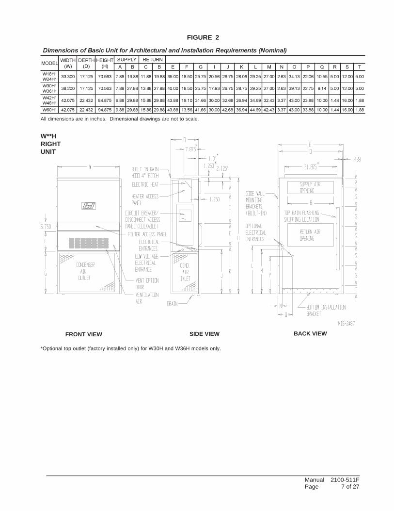
*Optional top outlet (factory installed only) for W30H and W36H models only.
FIGURE 2
)lanimoN(stnemeriuqeRnoitallatsnIdnalarutcetihcrAroftinUcisaBfosnoisnemiD
LEDOMHTDIW
)W(
HTPED
)D(
THGIEH
)H(
YLPPUS NRUTER
A B C B E F G I J K L M N O P Q R S T
1H81W
1H42W003.33 521.71 365.07 88.7 88.91 88.11 88.91 00.53 05.81 57.52 65.02 57.62 60.82 52.92 00.72 36.2 31.43 60.22 55.01 00.5 00.21 00.5
1H03W
1H63W002.83 521.71 365.07 88.7 88.72 88.31 88.72 00.04 05.81 57.52 39.71 57.62 57.82 52.92 00.72 36.2 31.93 57.22 41.9 00.5 00.21 00.5
1H24W
1H84W570.24 234.22 578.48 88.9 88.92 88.51 88.92 88.34 01.91 66.13 00.03 86.23 49.62 96.43 34.23 73.3 00.34 88.32 00.01 44.1 00.61 88.1
1H06W 570.24 234.22 578.49 88.9 88.92 88.51 88.92 88.34 65.31 66.14 00.03 86.24 49.63 96.44 34.24 73.3 00.34 88.33 00.01 44.1 00.61 88.1
All dimensions are in inches. Dimensional drawings are not to scale.
W**HRIGHTUNIT
SIDE VIEW BACK VIEWFRONT VIEW

Manual 2100-511FPage 8 of 27
FIG
UR
E 3
AW
18H
1, W
24H
1M
OU
NTI
NG
INST
RU
CTI
ON
S

Manual 2100-511FPage 9 of 27
FIG
UR
E 3
BW
30H
1, W
36H
1M
OU
NTI
NG
INST
RU
CTI
ON
S
Manual 2100-511FPage 10 of 27
FIG
UR
E 3
CW
42H
1, W
48H
1, W
60H
1M
OU
NTI
NG
INST
RU
CTI
ON
S

Manual 2100-511FPage 11 of 27
FIGURE 4ELECTRIC HEAT CLEARANCE
W30H1, W36H1, W42H1, W48H1, W60H1
WARNINGA minimum of 1/4 inch clearance must be maintained betweenthe supply air duct and combustible materials. This is requiredfor the first 3 feet of ducting.
It is important to insure that the 1/4 inch minimum spacing ismaintained at all points.
Failure to do this could result in overheating the combustiblematerial and may result in a fire causing damage, injury or death.
SIDE SECTION VIEW OF SUPPLY AIR DUCT FORWALL MOUNTED UNIT SHOWING 1/4 INCHCLEARANCE TO COMBUSTIBLE SURFACES.
Manual 2100-511FPage 12 of 27
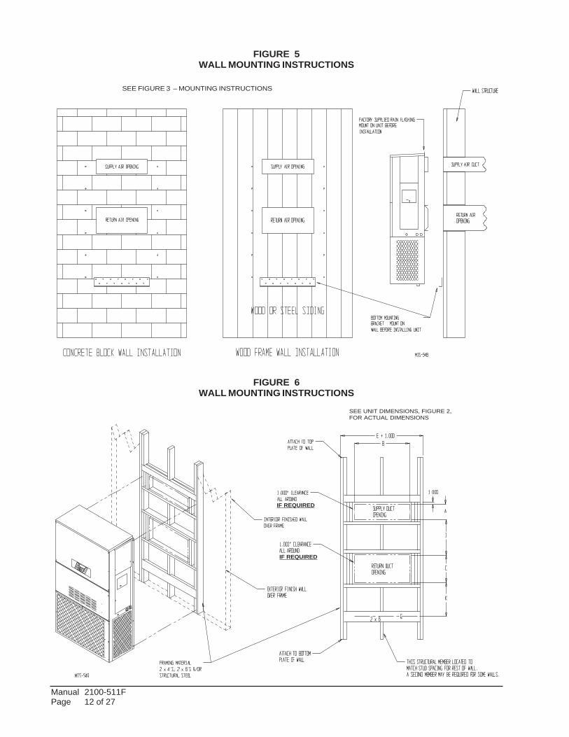
FIGURE 5WALL MOUNTING INSTRUCTIONS
FIGURE 6WALL MOUNTING INSTRUCTIONS
SEE FIGURE 3 – MOUNTING INSTRUCTIONS
SEE UNIT DIMENSIONS, FIGURE 2,FOR ACTUAL DIMENSIONS
IF REQUIRED
IF REQUIRED

Manual 2100-511FPage 13 of 27
FIGURE 7COMMON WALL MOUNTING INSTALLATIONS

Manual 2100-511FPage 14 of 27
WIRING – MAIN POWERRefer to the unit rating plate for wire sizing informationand maximum fuse or “HACR” type circuit breakersize. Each outdoor unit is marked with a “MinimumCircuit Ampacity”. This means that the field wiringused must be sized to carry that amount of current.Depending on the installed KW of electric heat, theremay be two field power circuits required. If this is thecase, the unit serial plate will so indicate. All modelsare suitable only for connection with copper wire. Eachunit and/or wiring diagram will be marked “Use CopperConductors Only”. These instructions must be adheredto. Refer to the National Electrical Code (NEC) forcomplete current carrying capacity data on the variousinsulation grades of wiring material. All wiring mustconform to NEC and all local codes.
The electrical data lists fuse and wire sizes (75° Ccopper) for all models including the most commonlyused heater sizes. Also shown are the number of fieldpower circuits required for the various models withheaters.
The unit rating plate lists a “Maximum Time DelayRelay Fuse” or “HACR” type circuit breaker that is tobe used with the equipment. The correct size must beused for proper circuit protection and also to assure thatthere will be no nuisance tripping due to the momentaryhigh starting current of the compressor motor.
The disconnect access door on this unit may be lockedto prevent unauthorized access to the disconnect. Toconvert for the locking capability, bend the tab locatedin the bottom left-hand corner of the disconnect openingunder the disconnect access panel straight out. This tabwill now line up with the slot in the door. When shut, apadlock may be placed through the hole in the tabpreventing entry.
See “Start Up” section for important information onthree phase scroll compressor start ups.
See Table 4 for Electrical Specifications.
WIRING – LOW VOLTAGE WIRING230/208V, 1 phase and 3 phase equipment dual primaryvoltage transformers. All equipment leaves the factorywired on 240V tap. For 208V operation, reconnect from240V to 208V tap. The acceptable operating voltagerange for the 240 and 208V taps are:
TAP RANGE240 253 – 216208 220 – 187
NOTE: The voltage should be measured at the field powerconnection point in the unit and while the unit isoperating at full load (maximum amperageoperating condition).
For wiring size and connections, refer to Wiring Manual2100-516.
Manual 2100-511FPage 15 of 27
START UP
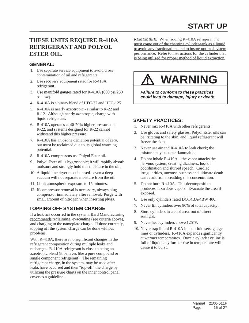
THESE UNITS REQUIRE R-410AREFRIGERANT AND POLYOLESTER OIL.
GENERAL:1. Use separate service equipment to avoid cross
contamination of oil and refrigerants.2. Use recovery equipment rated for R-410A
refrigerant.3. Use manifold gauges rated for R-410A (800 psi/250
psi low).4. R-410A is a binary blend of HFC-32 and HFC-125.5. R-410A is nearly azeotropic - similar to R-22 and
R-12. Although nearly azeotropic, charge withliquid refrigerant.
6. R-410A operates at 40-70% higher pressure thanR-22, and systems designed for R-22 cannotwithstand this higher pressure.
7. R-410A has an ozone depletion potential of zero,but must be reclaimed due to its global warmingpotential.
8. R-410A compressors use Polyol Ester oil.9. Polyol Ester oil is hygroscopic; it will rapidly absorb
moisture and strongly hold this moisture in the oil.10. A liquid line dryer must be used - even a deep
vacuum will not separate moisture from the oil.11. Limit atmospheric exposure to 15 minutes.12. If compressor removal is necessary, always plug
compressor immediately after removal. Purge withsmall amount of nitrogen when inserting plugs.
TOPPING OFF SYSTEM CHARGEIf a leak has occurred in the system, Bard Manufacturingrecommends reclaiming, evacuating (see criteria above),and charging to the nameplate charge. If done correctly,topping off the system charge can be done withoutproblems.With R-410A, there are no significant changes in therefrigerant composition during multiple leaks andrecharges. R-410A refrigerant is close to being anazeotropic blend (it behaves like a pure compound orsingle component refrigerant). The remainingrefrigerant charge, in the system, may be used afterleaks have occurred and then “top-off” the charge byutilizing the pressure charts on the inner control panelcover as a guideline.
REMEMBER: When adding R-410A refrigerant, itmust come out of the charging cylinder/tank as a liquidto avoid any fractionation, and to insure optimal systemperformance. Refer to instructions for the cylinder thatis being utilized for proper method of liquid extraction.
SAFETY PRACTICES:1. Never mix R-410A with other refrigerants.2. Use gloves and safety glasses, Polyol Ester oils can
be irritating to the skin, and liquid refrigerant willfreeze the skin.
3. Never use air and R-410A to leak check; themixture may become flammable.
4. Do not inhale R-410A – the vapor attacks thenervous system, creating dizziness, loss ofcoordination and slurred speech. Cardiacirregularities, unconsciousness and ultimate deathcan result from breathing this concentration.
5. Do not burn R-410A. This decompositionproduces hazardous vapors. Evacuate the area ifexposed.
6. Use only cylinders rated DOT4BA/4BW 400.7. Never fill cylinders over 80% of total capacity.8. Store cylinders in a cool area, out of direct
sunlight.9. Never heat cylinders above 125°F.10. Never trap liquid R-410A in manifold sets, gauge
lines or cylinders. R-410A expands significantlyat warmer temperatures. Once a cylinder or line isfull of liquid, any further rise in temperature willcause it to burst.
WARNINGFailure to conform to these practicescould lead to damage, injury or death.

Manual 2100-511FPage 16 of 27
START UP (Continued)
IMPORTANT INSTALLER NOTEFor improved start up performance wash the indoor coilwith a dish washing detergent.
HIGH & LOW PRESSURE SWITCHAll W**H wall mounted air conditioner series models aresupplied with a remote reset for the high and lowpressure switch. If tripped, this pressure switch may bereset by turning the thermostat off then back on again.
THREE PHASE SCROLL COMPRESSORSTART UP INFORMATIONScroll compressors, like several other types ofcompressors, will only compress in one rotationaldirection. Direction of rotation is not an issue withsingle phase compressors since they will always startand run in the proper direction.
However, three phase compressors will rotate in eitherdirection depending upon phasing of the power. Sincethere is a 50-50 chance of connecting power in such away as to cause rotation in the reverse direction,verification of proper rotation must be made.Verification of proper rotation direction is made byobserving that suction pressure drops and dischargepressure rises when the compressor is energized.Reverse rotation also results in an elevated sound levelover that with correct rotation, as well as substantiallyreduced current draw compared to tabulated values.
Verification of proper rotation must be made at thetime the equipment is put into service. If improperrotation is corrected at this time, there will be nonegative impact on the durability of the compressor.However, reverse operation for over one hour may havea negative impact on the bearing due to oil pump out.
NOTE: If compressor is allowed to run in reverse rotationfor several minutes, the compressor’s internalprotector will trip.
All three phase ZP compressors are wired identicallyinternally. As a result, once the correct phasing isdetermined for a specific system or installation,connecting properly phased power leads to the sameFusite terminal should maintain proper rotationdirection.
The direction of rotation of the compressor may bechanged by reversing any two line connections to theunit.
PHASE MONITORAll units with three phase scroll compressors areequipped with a 3 phase line monitor to preventcompressor damage due to phase reversal.
The phase monitor in this unit is equipped with twoLEDs. If the Y signal is present at the phase monitorand phases are correct the green LED will light.
If phases are reversed, the red fault LED will be lit andcompressor operation is inhibited.
If a fault condition occurs, reverse two of the supplyleads to the unit. Do not reverse any of the unit factorywires as damage may occur.
CONDENSER FAN OPERATIONApplies to W42, W48 and W60 models only. Thecondenser fan motor on 230/208 volt, one and threephase, 60 HZ units is a two-speed motor that comesfactory wired on high speed for peak performance. Ifambient conditions permit, it can be reconnected to lowspeed (red wire) for lower sound level. See wiringdiagram.
50 HZ models must have fan wired on low speed.These models are factory wired on low speed.
SERVICE HINTS1. Caution owner/operator to maintain clean air filters
at all times. Also, not to needlessly close off supplyand return air registers. This reduces airflowthrough the system, which shortens equipmentservice life as well as increasing operating costs.
2. Check all power fuses or circuit breakers to be surethey are the correct rating.
3. Periodic cleaning of the outdoor coil to permit fulland unrestricted airflow circulation is essential.
Manual 2100-511FPage 17 of 27
SEQUENCE OF OPERATIONCOOLING – Circuit R-Y makes at thermostat pulling incompressor contactor, starting the compressor and outdoormotor. The G (indoor motor) circuit is automatically completedon any call for cooling operation or can be energized by manualfan switch on subbase for constant air circulation.HEATING – A 24V solenoid coil on reversing valve controlsheating cycle operation. Two thermostat options, one allowing“Auto” changeover from cycle to cycle and the other constantlyenergizing solenoid coil during heating season, and thuseliminating pressure equalization noise except during defrost,are to be used. On “Auto” option a circuit is completed from R-W1 and R-Y on each heating “on” cycle, energizing reversingvalve solenoid and pulling in compressor contactor startingcompressor and outdoor motor. R-G also make starting indoorblower motor. Heat pump heating cycle now in operation. Thesecond option has no “Auto” changeover position, but insteadenergizes the reversing valve solenoid constantly whenever thesystem switch on subbase is placed in “Heat” position, the “B”terminal being constantly energized from R. A Thermostatdemand for heat completes R-Y circuit, pulling in compressorcontactor starting compressor and outdoor motor. R-G alsomake starting indoor blower motor.
PRESSURE SERVICE PORTSHigh and low pressure service ports are installed on all unitsso that the system operating pressures can be observed.Pressure tables can be found later in the manual covering allmodels. It is imperative to match the correct pressure tableto the unit by model number. See Tables 3A & 3B.
DEFROST CYCLEThe defrost cycle is controlled by temperature and time onthe solid state heat pump control.When the outdoor temperature is in the lower 40°Ftemperature range or colder, the outdoor coil temperature is32°F or below. This coil temperature is sensed by the coiltemperature sensor mounted near the bottom of the outdoorcoil. Once coil temperature reaches 30°F or below, the coiltemperature sensor sends a signal to the control logic of theheat pump control and the defrost timer will startaccumulating run time.After 30, 60 or 90 minutes of heat pump operation at 30°F orbelow, the heat pump control will place the system in thedefrost mode.During the defrost mode, the refrigerant cycle switches backto the cooling cycle, the outdoor motor stops, electric heatersare energized, and hot gas passing through the outdoor coilmelts any accumulated frost. When the temperature rises toapproximately 57°F, the coil temperature sensor will send asignal to the heat pump control which will return the systemto heating operations automatically.If some abnormal or temporary condition such as a highwind causes the heat pump to have a prolonged defrostcycle, the heat pump control will restore the system toheating operation automatically after 8 minutes.The heat pump defrost control board has an option of 30, 60or 90-minute setting. By default, this unit is shipped fromthe factory with the defrost time on the 60 minute pin. Ifcircumstances require a change to another time, remove the
wire from the 60-minute terminal and reconnect to thedesired terminal. Refer to Figure 8.There is a cycle speed up jumper on the control. This can beused for testing purposes to reduce the time between defrostcycle operation without waiting for time to elapse.Use a small screwdriver or other metallic object, or another¼ inch QC, to short between the SPEEDUP terminals toaccelerate the HPC timer and initiate defrost.Be careful not to touch any other terminals with theinstrument used to short the SPEEDUP terminals. It may takeup to 10 seconds with the SPEEDUP terminals shorted for thespeedup to be completed and the defrost cycle to start.As soon as the defrost cycle kicks in remove the shortinginstrument from the SPEEDUP terminals. Otherwise thetiming will remain accelerated and run through the 1-minuteminimum defrost length sequence in a matter of seconds andwill automatically terminate the defrost sequence.There is an initiate defrost jumper (sen jump) on the controlthat can be used at any outdoor ambient during the heatingcycle to simulate a 0° coil temperature.This can be used to check defrost operation of the unit withoutwaiting for the outdoor ambient to fall into the defrost region.By placing a jumper across the SEN JMP terminals (a¼ inch QC terminal works best) the defrost sensor mountedon the outdoor coil is shunted out & will activate the timingcircuit. This permits the defrost cycle to be checked out inwarmer weather conditions without the outdoor temperaturehaving to fall into the defrost region.In order to terminate the defrost test the SEN JMP jumpermust be removed. If left in place too long, the compressorcould stop due to the high pressure control opening becauseof high pressure condition created by operating in thecooling mode with outdoor fan off. Pressure will rise fairlyfast as there is likely no actual frost on the outdoor coil inthis artificial test condition.There is also a 5-minute compressor time delay function builtinto the HPC. This is to protect the compressor from shortcycling conditions. The board’s LED will have a fast blink ratewhen in the compressor time delay. In some instances, it ishelpful to the service technician to override or speed up thistiming period, and shorting out the SPEEDUP terminals for afew seconds can do this.Low Pressure Switch Bypass Operation - The control has aselectable (SW1) low pressure switch bypass set up to ignorethe low pressure switch input during the first (30, 60, 120 or 180seconds) of “Y” operation.After this period expires, the control will then monitor the lowpressure switch input normally to make sure that the switch isclosed during “Y” operation.High Pressure Switch Operation - The control has a built-inlockout system that allows the unit to have the high pressureswitch trip up to two times in one hour and only encounter a“soft” lockout. A “soft” lockout shuts the compressor off andwaits for the pressure switch to reset, which at that point thenallows the compressor to be restarted as long as the 5-minuteshort cycle timer has run out. If the high pressure switch trips athird time within one hour, the unit is in “hard” lockout indicatingsomething is certainly wrong and it will not restart itself.

Manual 2100-511FPage 18 of 27
120*
SW1
SW2 TIME (SEC)
OFFOFFONON
OFFON OFFON
3060
180
MIS-2668 A
OFF
LOW PRESSURE BYPASS TIMER SWITCH*(FACTORY SETTING 120 SECONDS)
ACCUMULATED DEFROST TIME TIMER (FACTORY SETTING 60 MIN.)
ON
FIGURE 8DEFROST CONTROL BOARD

Manual 2100-511FPage 19 of 27
TROUBLESHOOTINGSOLID STATE HEAT PUMP CONTROLTROUBLESHOOTING PROCEDURE1. NOTE: A thorough understanding of the defrost
cycle sequence is essential. Review that sectionearlier in this manual prior to troubleshooting thecontrol. Turn on AC power supply to unit.
2. Turn thermostat blower switch to “fan on” – theindoor blower should start. (If it doesn’t,troubleshoot indoor unit and correct problem.)
3. Turn thermostat blower to “auto” position. Indoorblower should stop. NOTE: Many models have a1-minute blower time delay on “off” command;wait for this to time-out.
4. Set system switch to “heat” or “cool”. Adjustthermostat to call for heat or cool. The indoorblower, compressor and outdoor fan should start.
NOTE: If there was no power to 24 volt transformer,the compressor and outdoor fan motor willnot start for 5 minutes. This is because ofthe compressor short cycle protection.
TABLE 1TROUBLESHOOTING
motpmyS sesuaCelbissoP&kcehC,noitpircseD riapeR/kcehCotwoH&tahW
lliwrosserpmoCgnitaeh(tratston
)gniloocro
.noitanimulliDELrofkcehC.1?)gnihsalf(draobehtnodetanimulliDELnaerehtsI
3#petSotog=oN;2#petSotog=seY
.sedocrorrerofkcehC.2?edoCagnihsalfDELehtsI
8#petSotog=oN;4#petSotog=seY
.draobtarewoprofkcehC.3?CdnaRneewtebCAstlov42erehtsI
9#petSotog=oN;31#petSotog=seY
.sedockcehC.4?gniknilbsiedoctahW
5#petSotog,knilBtsaF;7#petSotog,"2"edoC;6#petSotog,"1"edoC
.evitcayaledrosserpmoC.5."snippudeeps"s'draobpmujroyaledetunim5roftiaW
.1#petSotkcabog,dedeenllitsfi;noitareporeporprofkcehC
.tluaferusserpwoL.6 .serusserptinudnatiucricgniriwkcehC
.tluaferusserphgiH.7 .serusserptinudnatiucricgniriwkcehC
.langistupnirosserpmoCrofkcehC.8?CdnaYneewtebCAstlov42erehtsI
11#petSotog=oN;01#petSotog=seY
.draobotrewopoN.9 .tcerrocnisigniriwtinuehtrodabsiremrofsnarteht,egatlovtinuevahtonseodrehtietinuehT
.langistuptuorosserpmoCrofkcehC.01?C&CCneewtebCAstlov42erehtsI
31#petSotog=oN;21#petSotog=seY
.langistupnirosserpmoc"Y"oN.11 yllanifdna,)rotinoMesahPnonoitcesees(tinufoesahptcerrocni,gniriwtatsomrehtkcehC.gniriwtinu
.langistuptuorosserpmoc"CC"oN.21 .rosserpmockcehcyllanifdnanoitareporeporprofrotcatnocrosserpmockcehC
.draobytluaF.31 .draobtsorfedecalpeR
rotomroodtuonaFnurtonseod
gnitaehrognilooc(gnirudtpecxe
)tsorfed
evitcefedlortnocpmuptaeH)CN-moC(.lortnocpmuptaehnoyalernafssorcakcehC
.lortnocpmuptaehecalpeR
evitcefedrotoM .rotomecalpeR.gnidniwrotomdetrohsroneporofkcehC
evitcefedroticapacrotoM .roticapacecalpeR.roticapacdetrohsroneporofkcehC.gnitarroticapackcehC
evlavgnisreveRezigrenetonseod
)ylnognitaeh(evitcefedlortnocpmuptaeH
.C-BdnaC-VRneewtebV42rofkcehC.gniriwtiucriclortnockcehC.1lortnocpmuptaehecalpeR.2
evitcefedliocdionelosevlavgnisreveR.liocdetrohsroneporofkcehC
.liocdionelosecalpeR
ogtonlliwtinUtsorfedotni
)ylnognitaeh(evitcefedlortnocpmuptaehrorosneserutarepmeT
NES"dnaslanimret"PUDEEPS"ssorcarepmujdnadraobmorfrosneserutarepmettcennocsiD.etunimenonihtiwelcyctsorfedahguorhtogottinuehtesuacdluohssihT.slanimret"PMJ
.rosneserutarepmetecalper,elcyctsorfedhguorhtseogtinufI.1.lortnocpmuptaehecalper,elcyctsorfedhguorhtogtonseodtinufI.2
emoctonlliwtinUtsorfedfotuo)ylnognitaeh(
evitcefedlortnocpmuptaehrorosneserutarepmeT
.lanimret"PUDEEPS"ssorcarepmuJ.etunimenonihtiwtsorfedfotuoemocottinuehtesuacdluohssihT
.rosneserutarepmetecalper,elcyctsorfedfotuosemoctinufI.1.lortnocpmuptaehecalper,elcyctsorfedfotuoemoctonseodtinufI.2
LED BLINK CODESBLINK FUNCTIONSlow Normal function (1.0 sec on/1.0 sec off)Fast ASCD timer active (0.1 sec on/0.1 sec off)1 Low pressure switch failure2 High pressure switch failure/“Soft” Lockout3 Defrost mode active4 High pressure switch failure/“Hard” Lockout

Manual 2100-511FPage 20 of 27
CHECKING TEMPERATURE SENSOROUTSIDE UNIT CIRCUIT1. Disconnect temperature sensor from board and from
outdoor coil.
2. Use an ohmmeter and measure the resistance of thesensor. Also use ohmmeter to check for short oropen.
3. Check resistance reading to chart of resistance. Usesensor ambient temperature. (Tolerance of part is± 10%.)
4. If sensor resistance reads very low, then sensor isshorted and will not allow proper operation of theheat pump control.
5. If sensor is out of tolerance, shorted, open or readsvery low ohms then it should be replaced.
F R F R F R F R
0.52-0.42-0.32-0.22-0.12-0.02-0.91-0.81-0.71-0.61-0.51-0.41-0.31-0.21-0.11-0.01-0.9-0.8-0.7-0.6-0.5-0.4-0.3-0.2-0.1-0.00.10.20.30.40.50.60.70.80.90.010.110.21
1786919900915853818137719821717845614099519254515539414734416759316594316050319126219802218018112724115750110107014753010620014607918939800199318817358996281210823677032570192707607705868146699346944265650654785
0.310.410.510.610.710.810.910.020.120.220.320.420.520.620.720.820.920.030.130.230.330.430.530.630.730.830.930.040.140.240.340.440.540.640.740.840.940.05
5896548255046351502541505820940957400264558444553459224770148989375783256733856384553545434753343623327130480368992751925538277572328622906238352696420304248332857220512216512989025340269891
0.350.250.350.450.550.650.750.850.950.060.160.260.360.460.560.660.760.860.960.070.170.270.370.470.570.670.770.870.970.080.180.280.380.480.580.680.780.88
47391768815738198971434714896174561221610175101351129414454177141028314743173131018212942138121388111951170311130112670110501742010000106796259992977092688356894480528750896876867
0.980.090.190.290.390.490.590.690.790.890.990.0010.1010.2010.3010.4010.5010.6010.7010.8010.9010.0110.1110.2110.3110.4110.5110.6110.7110.8110.9110.0210.1210.2210.3210.421
705743375617000704863866135638369326890616957285796507556445623580254905289437847674366426544644763447242814390460041293838375738763106362532543
TEMPERATURE F VS. RESISTANCE R OF TEMPERATURE SENSOR

Manual 2100-511FPage 21 of 27
TROUBLESHOOTING
FIGURE 9FAN BLADE SETTING
TABLE 2FAN BLADE DIMENSION
REMOVAL OF FAN SHROUD1. Disconnect all power to the unit.
2. Remove the screws holding both grilles, one on eachside of unit, and remove grilles.
3. Remove screws holding fan shroud to condenser andbottom. Nine (9) screws.
4. Unwire condenser fan motor.
5. Slide complete motor, fan blade, and shroudassembly out the left side of the unit.
6. Service motor/fan as needed.
7. Reverse steps to reinstall.
R-410AREFRIGERANT CHARGEThis unit was charged at the factory with the quantity ofrefrigerant listed on the serial plate. AHRI capacity andefficiency ratings were determined by testing with thisrefrigerant charge quantity.
The following pressure tables show nominal pressuresfor the units. Since many installation specific situationscan affect the pressure readings, this information shouldonly be used by certified technicians as a guide forevaluating proper system performance. They shall notbe used to adjust charge. If charge is in doubt, reclaim,evacuate and recharge the unit to the serial plate charge.
ledoMnoisnemiD
A
1H81W1H42W
"00.1
1H03W1H63W
"52.1
1H24W1H84W1H06W
"57.1
"A"
AIRFLOW
MIS-1724
FAN BLADE SETTING DIMENSIONSShown in Figure 9 is the correct fan blade setting forproper air delivery across the outdoor coil. Refer toTable 2 for unit specific dimension.
Any service work requiring removal or adjustment inthe fan and/or motor area will require that thedimensions below be checked and blade adjusted in orout on the motor shaft accordingly.

Manual 2100-511FPage 22 of 27
TABLE 3ACOOLING PRESSURE TABLE
Low side pressure ± 4 PSIGHigh side pressure ± 10 PSIGTables are based upon rated CFM (airflow) across the evaporator coil. If there is any doubt as to correct operating charge being in the system, the chargeshould be removed, system evacuated and recharged to serial plate charge weight.NOTE: Pressure table based on high speed condenser fan operation. If condensing pressures appear elevated check condenser fan wiring.See “Condenser Fan Operation”.
Air Temperature Entering Outdoor Coil °F
ledoMriAnruteRerutarepmeT erusserP 57 08 58 09 59 001 501 011 511 021
1H81W
BD.ged57BW.ged26
ediSwoLediShgiH
231292
431113
731233
831353
041673
241004
441424
641054
841774
051505
BD.ged08BW.ged76
ediSwoLediShgiH
141992
341913
641043
841263
051683
251014
451534
651264
851984
061815
BD.ged58BW.ged27
ediSwoLediShgiH
641903
841033
151253
351573
551004
751424
951054
161874
461605
661635
1H42W
BD.ged57BW.ged26
ediSwoLediShgiH
421923
621153
821373
131893
331324
531944
731574
831305
041135
241165
BD.ged08BW.ged76
ediSwoLediShgiH
331733
531063
731383
041804
241434
441064
641784
841615
051545
251575
BD.ged58BW.ged27
ediSwoLediShgiH
831943
041373
241693
541224
741944
941674
151405
351435
551465
751595
1H03W
BD.ged57BW.ged26
ediSwoLediShgiH
521623
821053
131373
331893
631324
731844
931274
141694
341225
541745
BD.ged08BW.ged76
ediSwoLediShgiH
431433
731953
041383
241804
441834
741954
941484
151905
351535
551165
BD.ged58BW.ged27
ediSwoLediShgiH
931643
241273
541693
741224
051944
251574
451105
651725
851455
061185
1H63W
BD.ged57BW.ged26
ediSwoLediShgiH
221923
421153
621573
821993
031424
231944
531674
731305
831035
141955
BD.ged08BW.ged76
ediSwoLediShgiH
131733
331063
531583
731904
731444
141164
441884
641615
841445
151375
BD.ged58BW.ged27
ediSwoLediShgiH
631943
831373
041893
241324
441054
641774
941505
151435
351365
651395
1H24W
BD.ged57BW.ged26
ediSwoLediShgiH
721453
031273
231293
431314
531734
631164
731884
731615
731645
631875
BD.ged08BW.ged76
ediSwoLediShgiH
631363
931283
141204
341424
341254
541374
641005
641925
641065
541395
BD.ged58BW.ged27
ediSwoLediShgiH
141673
441593
641614
841934
941464
051094
151815
151845
151085
051416
1H84W
BD.ged57BW.ged26
ediSwoLediShgiH
921253
231473
431893
631224
731944
931674
141505
341535
541665
641006
BD.ged08BW.ged76
ediSwoLediShgiH
831163
141483
341804
541334
741064
941884
151815
351945
551185
651516
BD.ged58BW.ged27
ediSwoLediShgiH
341473
641793
841224
051844
251674
451505
651635
851865
061106
161736
1H06W
BD.ged57BW.ged26
ediSwoLediShgiH
621233
821253
131373
331793
531124
731844
931674
141505
341635
541865
BD.ged08BW.ged76
ediSwoLediShgiH
531143
731163
041383
241704
341434
741954
941884
151815
351055
551385
BD.ged58BW.ged27
ediSwoLediShgiH
041353
241473
541693
741124
941744
251574
451505
651635
851965
061306
TABLE 3BHEATING PRESSURES – (ALL TEMPERATURES °F)
ledoMriAnruteRerutarepmeT erusserP 0 5 01 51 02 52 03 53 04 54 05 55 06
H81W .ged07ediSwoLediShgiH
84092
25582
65282
16282
66582
27092
97792
78703
59913
401433
411253
421273
531493
H42W .ged07ediSwoLediShgiH
75292
55692
55103
75703
95413
46323
07233
77243
68453
69763
801083
121593
531114
H03W .ged07ediSwoLediShgiH
35452
35662
55872
85092
16103
66213
27223
08233
88243
79153
801063
911963
231773
H63W .ged07ediSwoLediShgiH
74182
94282
15382
55782
95292
46003
07803
77913
58133
39543
301163
311973
421893
H24W .ged07ediSwoLediShgiH
05992
05003
25303
45803
85413
26223
86133
57243
48553
39073
401683
511404
821324
H84W .ged07ediSwoLediShgiH
24862
54072
94472
45872
95482
46192
07892
77703
48713
29723
001933
901253
811663
H06W .ged07ediSwoLediShgiH
93492
34692
74003
25503
85113
36913
07823
67833
48943
29263
001673
901193
811804

Manual 2100-511FPage 23 of 27
TABLE 4
1 Maximum size of the time delay fuse or HACR type circuit breaker for protection of field wiring conductors.2 Based on 75C copper wire. All wiring must conform to the National Electrical Code and all local codes.3 These “Minimum Circuit Ampacity” values are to be used for sizing the field power conductors. Refer to the National Electrical code (latest version), Article
310 for power conductor sizing.
Caution: When more than one field power circuit is run through one conduit, the conductors must be derated. Pay special attention to note 8 of Table 310regarding Ampacity Adjustment Factors when more than three (3) current carrying conductors are in a raceway.
* Top outlet supply option is available only factory installed and only on the selected models.
IMPORTANT: While this electrical data is presented as a guide, it is important to electrically connect properly sized fuses and conductor wires inaccordance with the National Electrical Code and all local codes.
tiucriCelgniS tiucriClauD
ledoMdetaRstloV
esahPdna
dleiF.oNrewoPstiucriC
4 muminiMtiucriCyticapmA
1 mumixaMesuFlanretxE.rkrB.tkCro
2 dleiFrewoPeziSeriW
2 dnuorGeriW
4 muminiMtiucriCyticapmA
1 mumixaMesuFlanretxE
rekaerB.tkCro
2 dleiFrewoPeziSeriW
2 dnuorGeziSeriW
A.tkC B.tkC A.tkC B.tkC A.tkC B.tkC A.tkC B.tkCZ0A,00A-1H81W
40A3 80A
1-802/032111
617385
020406
2186
210101
Z0A,00A-1H42W40A
3 80A1-802/032
111
424456
520507
0186
0101
8 44 12 54 52 8 01 01 0142W 1H Z0B,00B-
60B3-802/032
11
7153
0204
218
2101
42W 1H Z0C,00C-60C
3-06411
1112
5152
4101
4101
*Z0A,00A-1H03W*50A
3 *01A1-802/032
11
2ro1
420567
530508
884
0101
8 05 62 05 03 8 01 01 01*Z0B,00B-1H03W
60B3 *90B
3-802/032111
816354
520454
0188
010101
*Z0C,00C-1H03W60C
3 *90C51C
3-064
1111
11025262
51025203
41210101
41210101
*Z0A,00A-1H63W50A
3 *01A5 51A
1-802/032
11
2ro12ro1
92551848
04060909
8644
0101
88
5555
6225
0606
0306
66
016
0101
0101
*Z0B,00B-1H63W60B
3 *90B5 51B
3-802/032
1111
32140515
03540506
01888
01010101
*Z0C,00C-1H63W60C
3 *90C51C
3-064
1111
21125262
51525203
41010101
41010101
Z0A,00A-1H24W50A
3 01A5 51A
1-802/032
11
2ro12ro1
63268888
05070909
8633
01888
636363
622525
050505
030606
888
0166
010101
010101
Z0B,00B-1H24W60B
3 90B5 51B
3-802/032
1111
62443535
53050606
8866
01010101
Z0C,00C-1H24W60C
3 90C5 51C
3-064
1111
31226262
51520303
41010101
41010101
Z0A,00A-1H84W40A50A
3 01A5 51A5 02A
1-802/032
11
2ro12ro12ro12ro1
7385369898111
0506070909521
866332
0101
8886
73737395
62252525
05050506
03060606
8886
01666
01010101
01010101
Z0B,00B-1H84W60B
3 90B5 51B5 81B
3-802/032
1111
2ro1
9274656526
5305060607
88666
01010101
8 43 82 04 03 8 01 01 01Z0C,00C-1H84W
3 90C5 51C
3-064111
417272
020303
210101
210101
Z0A,00A-1H06W50A
3 01A5 51A5 02A
1-802/032
12ro12ro12ro12ro1
14763939111
0608001001521
84332
018886
14141495
62252525
06060606
03060606
8886
01666
01010101
01010101
Z0B,00B-1H06W3 90B5 51B5 81B
3-802/032
1111
82555526
04060607
8666
01010101 43 82 04 03 8 01 01 01
Z0C,00C-1H06W3 90C5 51C
3-064111
618282
020303
210101
210101
Electrical Specifications — W**H Series
Manual 2100-511FPage 24 of 27
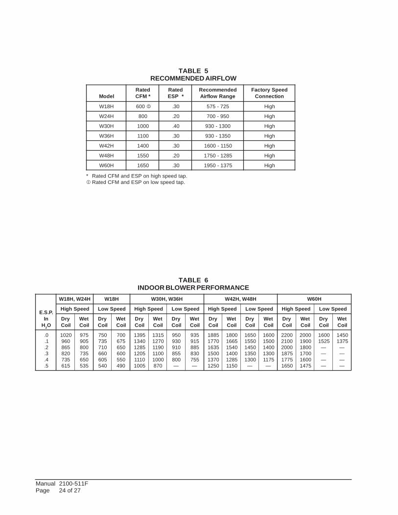
TABLE 5RECOMMENDED AIRFLOW
TABLE 6INDOOR BLOWER PERFORMANCE
ledoMdetaR*MFC
detaR*PSE
dednemmoceRegnaRwolfriA
deepSyrotcaFnoitcennoC
H81W 006 1 03. 527-575 hgiH
H42W 008 02. 059-007 hgiH
H03W 0001 04. 0031-039 hgiH
H63W 0011 03. 0531-039 hgiH
H24W 0041 03. 0511-0061 hgiH
H84W 0551 02. 5821-0571 hgiH
H06W 0561 03. 5731-0591 hgiH
.P.S.EnI
H2O
H42W,H81W H81W H63W,H03W H84W,H24W H06W
deepShgiH deepSwoL deepShgiH deepSwoL deepShgiH deepSwoL deepShgiH deepSwoL
yrDlioC
teWlioC
yrDlioC
teWlioC
yrDlioC
teWlioC
yrDlioC
teWlioC
yrDlioC
teWlioC
yrDlioC
teWlioC
yrDlioC
teWlioC
yrDlioC
teWlioC
0.1.2.3.4.5.
0201069568028537516
579509008537056535
057537017066506045
007576056006055094
593104315821502101115001
51310721091100110001
078
059039019558008
—
539519588038557
—
588107715361005107310521
008156610451004158210511
05610551054105310031
—
00610051004100315711
—
002200120002578157710561
000200910081007100615741
00615251
————
05415731
————
* Rated CFM and ESP on high speed tap.1 Rated CFM and ESP on low speed tap.

Manual 2100-511FPage 25 of 27
TABLES 7MAXIMUM ESP OF OPERATION
ELECTRIC HEAT ONLY
TABLE 8ELECTRIC HEAT
sledoM 1-V042 1-V802 3-V042 3-V802 3-V064
WK spmA HUTB spmA HUTB spmA HUTB spmA HUTB spmA HUTB
4 7.61 05631 4.41 04201
5 8.02 56071 1.81 00821
6 4.41 00502 5.21 06351 2.7 00502
8 3.33 00372 8.82 57402
9 7.12 00603 7.81 03032 8.01 00703
01 6.14 03143 2.63 00652
21 4.41 05904
51 5.26 05215 0.45 00483 2.63 00215 2.13 00483 0.81 00215
81 3.34 03416 5.73 00164
02 2.38 06286 1.27 00215
ledoMWKdeepS
1H24W 1H84W 1H06W
deepShgiH deepSwoL deepShgiH deepSwoL deepShgiH deepSwoL
00A-40A-50A-01A-51A-02A-
05.-----
05.05.05.-----
05.-----
05.54.54.-----
05.05.05.05.05.05.
05.05.05.54.54.54.
05.-----
05.05.05.05.
04.-----
52.52.52.52.
00B-90B-51B-81B-
05.05.05.-----
05.54.54.-----
05.05.05.05.
05.54.54.54.
05.05.05.05.
04.03.03.03.
00C-90C-51C-
05.05.05.
05.04.04.
05.05.05.
05.04.04.
05.05.05.
04.53.53.
ledoM PSE
1H81W1H42W
00A40A80A
05.05.04.
1H42W00B60B
05.05.
1H42W00C60C
05.05.
ledoM
teltuOtnorF teltuOpoT
woLdeepS
hgiHdeepS
woLdeepS
hgiHdeepS
1H03W1H63W
00A50A01A51A
05.04.53.53.
05.05.04.04.
05.04.52.AN
05.05.04.AN
1H03W1H63W
00B60B90B51B
05.04.53.53.
05.05.54.54.
05.AN03.AN
05.AN04.AN
1H03W1H63W
00C60C90C51C
05.05.03.03.
05.05.04.04.
05.AN53.AN
05.AN54.AN

Manual 2100-511FPage 26 of 27
W18
H1-
A
W24
H1-
A
W24
H1-
B
W24
H1-
C
W30
H1-
A
W30
H1-
B
W30
H1-
C
W36
H1-
A
W36
H1-
B
W36
H1-
C
W42
H1-
A
W42
H1-
B
W42
H1-
C
W48
H1-
A
W48
H1-
B
W48
H1-
C
W60
H1-
A
W60
H1-
B
W60
H1-
C
TABLE 9OPTIONAL ACCESSORIES
rebmuNtraP
40A-A20HWHE X
80A-A20HWHE X
40A-H42WHE X
80A-H42WHE X
60B-H42WHE X
50A-03HWHE X
01A-03HWHE X
50A-63HWHE X
01A-63HWHE X
51A-63HWHE X
60B-30HWHE X
60B-H63WHE X
90B-30HWHE X X
51B-H03WHE X
60C-A30CWHE X X
50A-24HWHE X X
01A-24HWHE X X
51A-24HWHE X X
02A-40-HWHE X X
60B-50HWHE X X
90B-50HWHE X X X
51B-50HWHE X X X
60C-24HWHE X
90C-A50HWHE X X X
51C-A50HWHE X X X
51A-40HWHE X
01A-40HWHE X
81B-H50WHE X X
A20-BCMW X
B20-BCMW X
A30-BCMW X
B30-BCMW X X
A60-BCMW X X
B50-BCMW X X
B70-BCMW X
A80-BCMW X X
A90-BCMW X
C10-DPMW X X X X X X
HE
ATE
R K
ITS
CIR
CU
IT B
REA
KER
(WM
CB
) &P
ULL
DIS
CO
NN
EC
T (W
MP
D)

Manual 2100-511FPage 27 of 27
TABLE 10VENT & CONTROL OPTIONS
W18
, W24
W30
, W36
W42
, W48
, W60
rebmuNtraP noitpircseD
41-CMC TDO X X X
51-CMC )ylnoesahP-1V032(tiKtratS 1 X X X
111KS )ylnoesahP-1V032(tiKtratS 2 X X X
82-CMC CAL X X X
2-DAFB dradnatS-repmaDriAhserFcirtemoraB X
2-POB etalPffOknalB X
2-DAFM repmaDriAhserFdezirotoM X
2-VRC nruteRgnirpS-rotalitneVlaicremmoC X
B2-MFIE rezimonocE X
2A-FVRE tloV032-rotalitneVyrevoceRygrenE X
3-DAFB dradnatS-repmaDriAhserFcirtemoraB X
3-POB etalPffOknalB X
3-DAFM repmaDriAhserFdezirotoM X
3-SVRC nruteRgnirpS-rotalitneVlaicremmoC X
3-PVRC nruteRrewoP-rotalitneVlaicremmoC X
C3-MFIE rezimonocE X
3A-FVRE tloV032-rotalitneVyrevoceRygrenE X
3C-FVRE tloV064-rotalitneVyrevoceRygrenE X
5-DAFB dradnatS-repmaDriAhserFcirtemoraB X
5-POB etalPffOknalB X
5-DAFM repmaDriAhserFdezirotoM X
5-SVRC nruteRgnirpS-rotalitneVlaicremmoC X
5-PVRC nruteRrewoP-rotalitneVlaicremmoC X
C5-MFIE rezimonocE X
5A-FVRE tloV032-rotalitneVyrevoceRygrenE X
5C-FVRE tloV064-rotalitneVyrevoceRygrenE X
1 PTCR Start Kit can be used with all -A single phase models. Increases starting torque 2-3x. Not used for -B or -C three phasemodels. Do not use if SK111 is used.
2 Start Capacitor and potential relay start kit can be used with all -A single phase models. Increases starting torque 9x. Not usedfor -B or -C three phase models. Do not use if CMC-15 is used.
Related Documents