INSTALLATION INSTRUCTIONS

Welcome message from author
This document is posted to help you gain knowledge. Please leave a comment to let me know what you think about it! Share it to your friends and learn new things together.
Transcript

INSTALLATION INSTRUCTIONS
INSTALLATION INSTRUCTIONS
• 3/4" and 1" DryFreight• TODCOLD™ Insulated• FleetStar• RouteMaster
FIG.1
TOOLS NEEDED:❏ Safety glasses❏ Stepladder❏ Tape measure❏ Six (6) C-clamps❏ Vice grips❏ Portable light❏ Welder❏ Cutting torch
❏ Hammer❏ Two (2) pieces of wood
(2" x 4")❏ Two (2) 1/2" dia. X 18"
winding bars❏ 7/16", 1/2" and 9/16"
wrenches
THESE INSTRUCTIONS COVER THE INSTALLATION OF THEFOLLOWING REAR DOORS WITH OUTSIDE CABLES ANDMAXIMUM SECURITY LOCK:
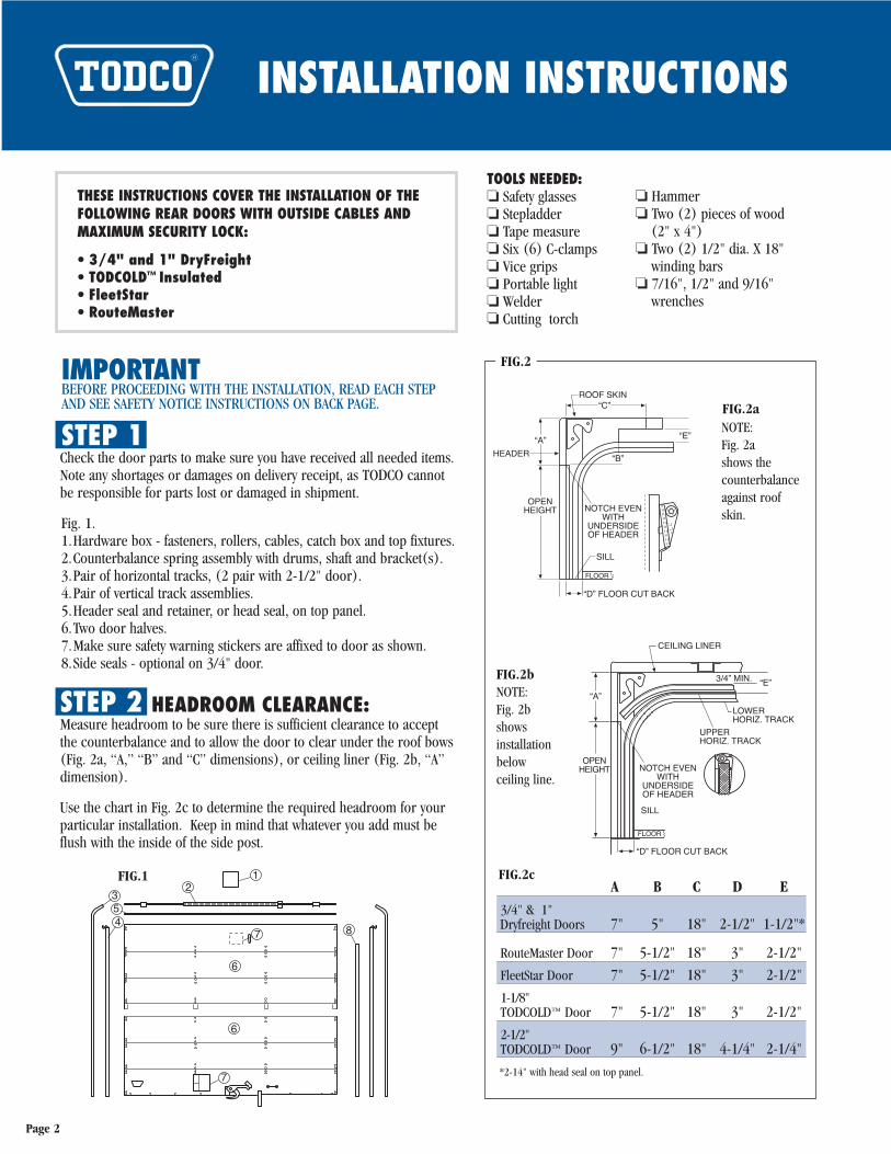
FIG.2a
FIG.2bNOTE:Fig. 2b shows installationbelow ceiling line.
NOTE: Fig. 2a shows thecounterbalanceagainst roofskin.
FIG.2IMPORTANTBEFORE PROCEEDING WITH THE INSTALLATION, READ EACH STEPAND SEE SAFETY NOTICE INSTRUCTIONS ON BACK PAGE.
STEP 1Check the door parts to make sure you have received all needed items.Note any shortages or damages on delivery receipt, as TODCO cannotbe responsible for parts lost or damaged in shipment.
Fig. 1.1.Hardware box - fasteners, rollers, cables, catch box and top fixtures.2.Counterbalance spring assembly with drums, shaft and bracket(s).3.Pair of horizontal tracks, (2 pair with 2-1/2" door).4.Pair of vertical track assemblies.5.Header seal and retainer, or head seal, on top panel.6.Two door halves.7.Make sure safety warning stickers are affixed to door as shown.8.Side seals - optional on 3/4" door.
STEP 2 HEADROOM CLEARANCE:Measure headroom to be sure there is sufficient clearance to accept the counterbalance and to allow the door to clear under the roof bows (Fig. 2a, “A,” “B” and “C” dimensions), or ceiling liner (Fig. 2b, “A”dimension).
Use the chart in Fig. 2c to determine the required headroom for yourparticular installation. Keep in mind that whatever you add must beflush with the inside of the side post.
A B C D E
3/4" & 1" Dryfreight Doors 7" 5" 18" 2-1/2" 1-1/2"*
RouteMaster Door 7" 5-1/2" 18" 3" 2-1/2"
FleetStar Door 7" 5-1/2" 18" 3" 2-1/2"
1-1/8"TODCOLD™ Door 7" 5-1/2" 18" 3" 2-1/2"
2-1/2"TODCOLD™ Door 9" 6-1/2" 18" 4-1/4" 2-1/4"
*2-14" with head seal on top panel.
FIG.2c
Page 2
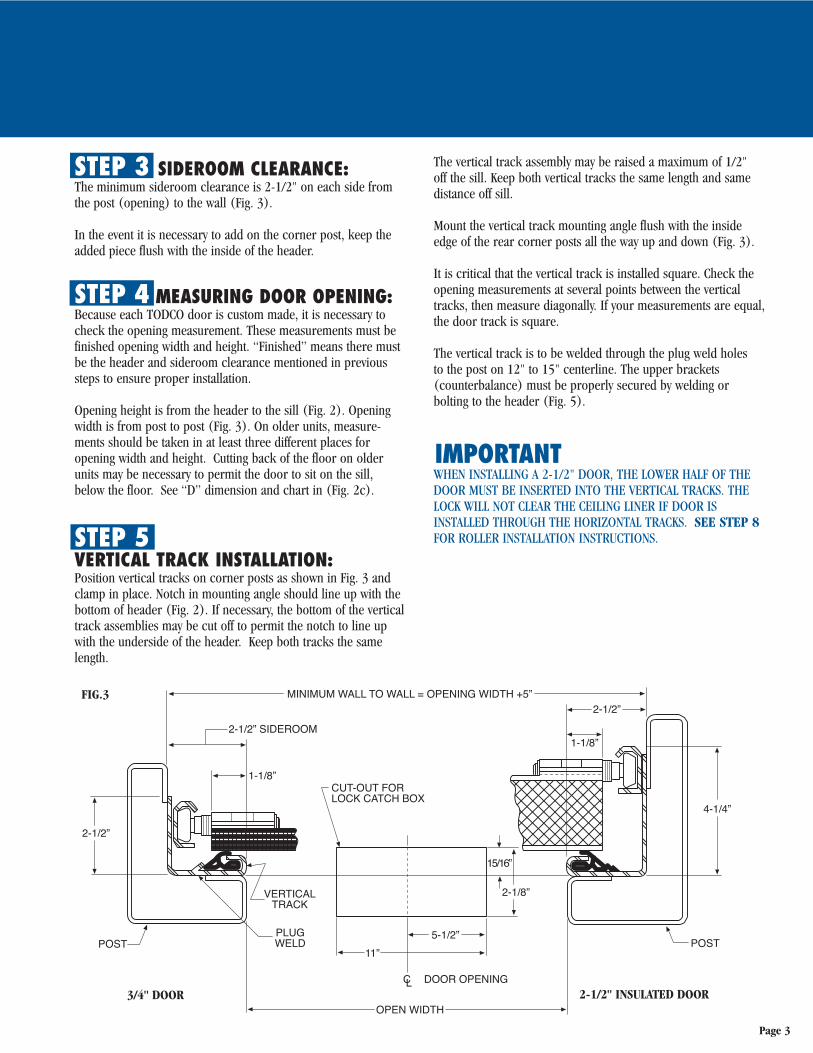
STEP 3 SIDEROOM CLEARANCE:The minimum sideroom clearance is 2-1/2" on each side fromthe post (opening) to the wall (Fig. 3).
In the event it is necessary to add on the corner post, keep theadded piece flush with the inside of the header.
STEP 4 MEASURING DOOR OPENING:Because each TODCO door is custom made, it is necessary tocheck the opening measurement. These measurements must befinished opening width and height. “Finished” means there mustbe the header and sideroom clearance mentioned in previoussteps to ensure proper installation.
Opening height is from the header to the sill (Fig. 2). Openingwidth is from post to post (Fig. 3). On older units, measure-ments should be taken in at least three different places for opening width and height. Cutting back of the floor on olderunits may be necessary to permit the door to sit on the sill,below the floor. See “D” dimension and chart in (Fig. 2c).
STEP 5VERTICAL TRACK INSTALLATION:Position vertical tracks on corner posts as shown in Fig. 3 andclamp in place. Notch in mounting angle should line up with thebottom of header (Fig. 2). If necessary, the bottom of the verticaltrack assemblies may be cut off to permit the notch to line upwith the underside of the header. Keep both tracks the samelength.
The vertical track assembly may be raised a maximum of 1/2" off the sill. Keep both vertical tracks the same length and samedistance off sill.
Mount the vertical track mounting angle flush with the insideedge of the rear corner posts all the way up and down (Fig. 3).
It is critical that the vertical track is installed square. Check theopening measurements at several points between the verticaltracks, then measure diagonally. If your measurements are equal,the door track is square.
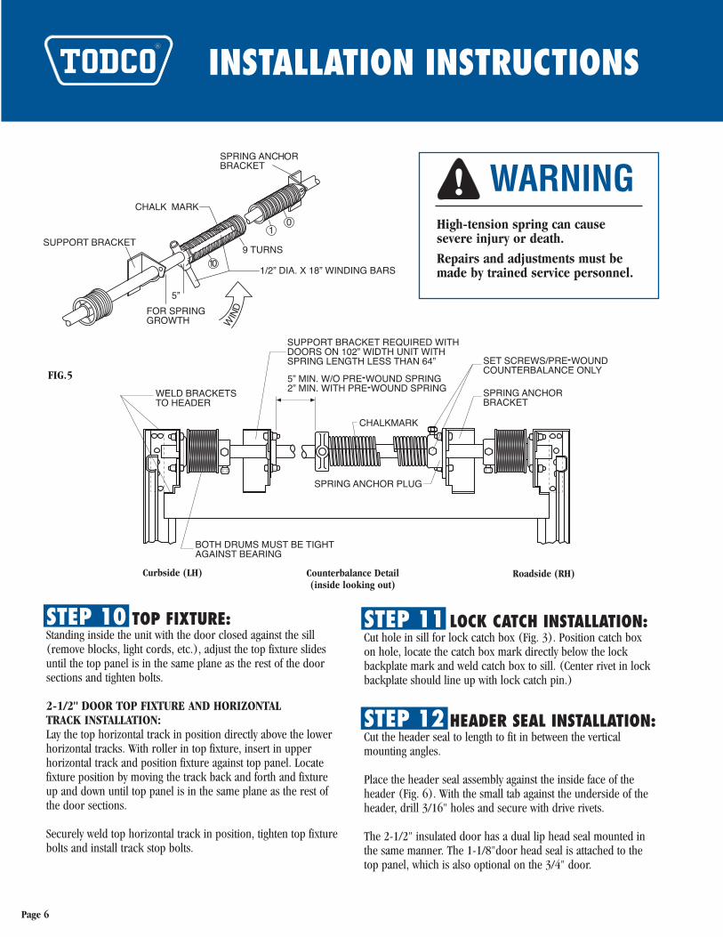
The vertical track is to be welded through the plug weld holes to the post on 12" to 15" centerline. The upper brackets (counterbalance) must be properly secured by welding or bolting to the header (Fig. 5).
IMPORTANTWHEN INSTALLING A 2-1/2" DOOR, THE LOWER HALF OF THEDOOR MUST BE INSERTED INTO THE VERTICAL TRACKS. THELOCK WILL NOT CLEAR THE CEILING LINER IF DOOR ISINSTALLED THROUGH THE HORIZONTAL TRACKS. SEE STEP 8FOR ROLLER INSTALLATION INSTRUCTIONS.
FIG.3
3/4" DOOR 2-1/2" INSULATED DOOR
Page 3
INSTALLATION INSTRUCTIONS
STEP 6HORIZONTAL TRACK INSTALLATION:The lower half of a 2-1/2" door is to be inserted before mountingthe horizontal tracks. The horizontal tracks must be installed 90 degrees with vertical tracks, within minimum clearancedimensions per chart (Fig. 2c).
The 2-1/2" door has dual horizontal tracks. Install the lower horizontal track (with mounting strip attached) 2-1/4"(minimum) below the liner.
It is important to maintain the same distance between the horizontal and vertical tracks. If wider than the vertical tracks,shim horizontal track accordingly.
Fasten horizontal tracks securely to provide adequate support for the door, and weld the full length of the couplers at the trackjoints.
Do not install the upper set of horizontal tracks on 2-1/2" doorat this time.
STEP 7COUNTERBALANCE INSTALLATION:If door is equipped with a pre-wound counterbalance, specialprecautions must be exercised when handling this assembly. Thespring on this type counterbalance is factory pre-wound and isunder tension.
DO NOT loosen any of the spring set screws until final installation of the pre-wound counterbalance detailed in Step 9.
Remove the bearing assembly from the roadside vertical track.Slide this bearing onto the right-hand cable drum end of thecounterbalance shaft. Insert the left end of the counterbalanceshaft into the bearing assembly of the curbside vertical track.Remount bearing to roadside vertical track assembly.
Position and align the spring anchor bracket on the inside of the header; be sure the shaft is not rubbing on the spring anchorcasting. Allow a minimum of 5" for spring growth (Fig. 5).FIRMLY SECURE SPRING ANCHOR BRACKET TO WITHSTAND THE STRONG TORQUE OF THE SPRING.
An additional counterbalance support bracket is required on102" wide units.
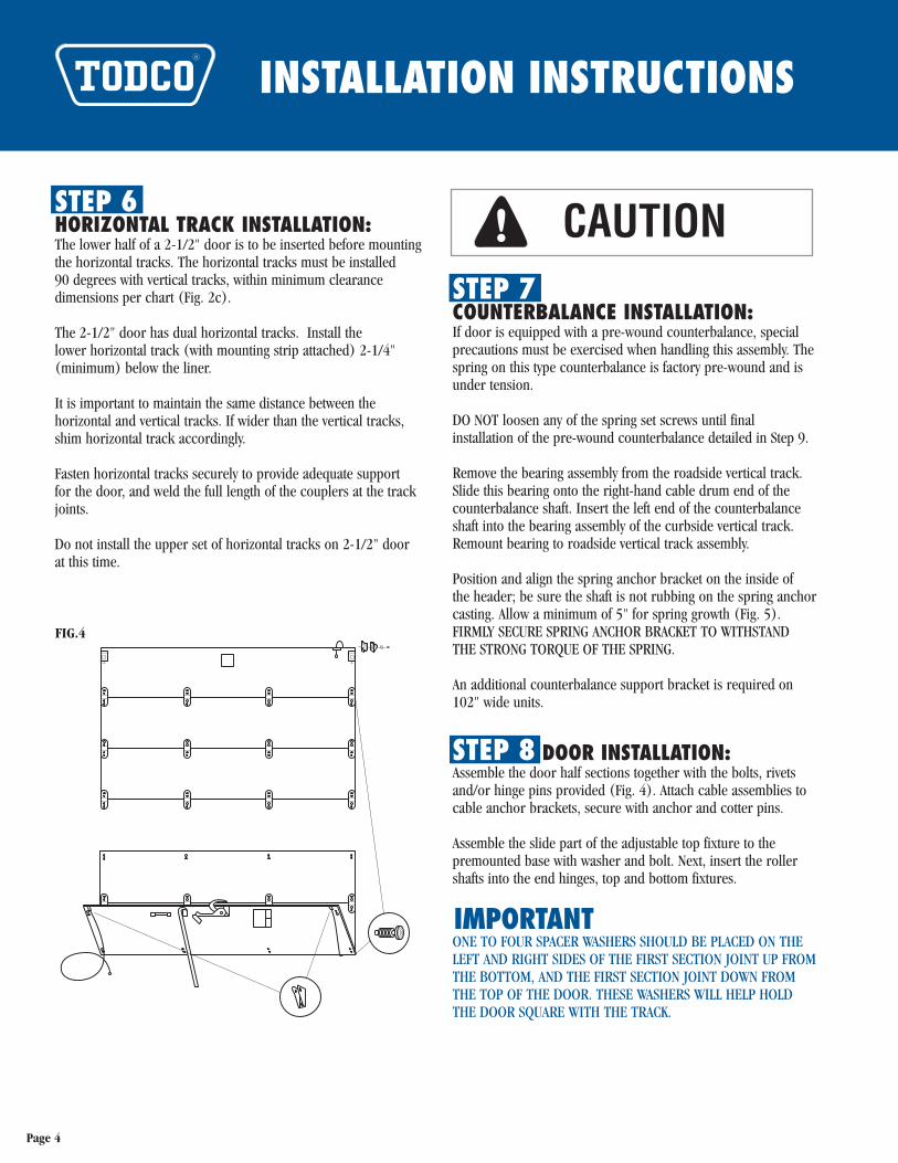
STEP 8 DOOR INSTALLATION:Assemble the door half sections together with the bolts, rivetsand/or hinge pins provided (Fig. 4). Attach cable assemblies tocable anchor brackets, secure with anchor and cotter pins.
Assemble the slide part of the adjustable top fixture to the premounted base with washer and bolt. Next, insert the rollershafts into the end hinges, top and bottom fixtures.
IMPORTANTONE TO FOUR SPACER WASHERS SHOULD BE PLACED ON THELEFT AND RIGHT SIDES OF THE FIRST SECTION JOINT UP FROMTHE BOTTOM, AND THE FIRST SECTION JOINT DOWN FROMTHE TOP OF THE DOOR. THESE WASHERS WILL HELP HOLDTHE DOOR SQUARE WITH THE TRACK.
FIG.4
CAUTION
Page 4
Do not install the top fixtures on the 2-1/2" door at this time.
On 2-1/2" door installation, insert the fasteners for the endhinges into the door bottom half. Drop in the top half of thedoor, bolt end hinges and drive pins in center hinges to connectdoor halves.
Before rolling the door into the tracks, bring the cable ends tothe top of the door and tape to the inside of top panel (Fig. 4).
If the unit has no other door, place two small blocks of the samesize under each corner of the door so a light may be placed inthe unit. The blocks will keep the door even while you wind thecables and counterbalance spring.
Insert door and carefully lower door, supporting door weightonto wood blocks on sill. Install track stop bolt in end of horizontal track.
With the door closed, bring the roadside cable up between thedrum and the header.
Hook the cable end in the slot in the outer groove of the rightcable drum. Starting in the first groove, wind the cable on thedrum, winding drum toward you. Make sure it properly tracksin each groove of the cable drum.
Take up the cable slack until snug; push the drum against thebearing and properly tighten both set screws. Now, clamp thecounterbalance shaft with vice grips, (handle of grips against theceiling) to hold the cable taut (Fig. 5).
Repeat the procedure with the curbside cable and drum.
IMPORTANT1. CABLE DRUMS MUST BE TIGHT AGAINST BEARINGS.2. CABLE IS PROPERLY TRACKING IN CABLE DRUM GROOVES.3. CABLES MUST HAVE EQUAL TENSION.4. SET SCREWS MUST BE TIGHT.
STEP 9 SPRING WINDING:To determine the amount of winds on the counterbalance spring,divide 10 into the door opening height in inches and add 3turns.
––––––––––Example: 75 divided by 10 = 7.5 turns + 3 turns = 10.5
or 10 and one-half turns.––––––––––
Run a chalk mark (Fig. 5) the full length of the counterbalancespring. Leave the vice grip clamped to the shaft to keep tensionon the cables.
Place a 1/2" diameter x 18" winding bar in the hole in the springwinding plug. Wind the spring by lifting up the bar. While hold-ing the first bar, place a second bar in the next hole and lift inthe same manner after removing the first bar. Repeat this untilthe correct number of complete turns are obtained by countingthe chalk marks which show up as stripes as the spring iswound.
Properly tighten both set screws on the spring winding plug andremove the vice grips from the counterbalance shaft.
IMPORTANTUSE 1/2" DIAMETER X 18" WINDING BARS ONLY. DO NOT USEBENT WINDING BARS, SCREWDRIVERS OR TAPERED PUNCHESFOR WINDING.
A properly counterbalanced door should, when stopped, remainat any given location. If the door leaves the floor by itself, thespring is wound too tight and a few quarter-turns should bereleased. If the door has any tendency to drop when stopped, afew more quarter-turns should be added.
SHALLOW HEADER COUNTERBALANCE: Call the Marion plant torequest a copy of drawing C-99725.
PRE-WOUND COUNTERBALANCE: If door is equipped with a pre-wound counterbalance, disregard above instructions andrelease spring tension as follows:
Make sure cables are attached to door and cable drums, thatcables are properly tensioned, and cable drums are properlysecured to shaft as noted in Step 8.
Clamp vice grips above roller to track, clamping door in downposition. Loosen and remove the two (2) set screws found inthe spring anchor plug (Fig. 5). This plug is found on the right-hand end (inside looking outside) of the spring. Spring tensionhas now been transferred to the cables. Remove vice grips andcheck door operation.
WARNING
CAUTION
High-tension spring can cause severe injury or death.
Page 5
INSTALLATION INSTRUCTIONS
STEP 10 TOP FIXTURE:Standing inside the unit with the door closed against the sill(remove blocks, light cords, etc.), adjust the top fixture slidesuntil the top panel is in the same plane as the rest of the doorsections and tighten bolts.
2-1/2" DOOR TOP FIXTURE AND HORIZONTAL TRACK INSTALLATION: Lay the top horizontal track in position directly above the lowerhorizontal tracks. With roller in top fixture, insert in upper horizontal track and position fixture against top panel. Locatefixture position by moving the track back and forth and fixtureup and down until top panel is in the same plane as the rest ofthe door sections.
Securely weld top horizontal track in position, tighten top fixturebolts and install track stop bolts.
FIG.5
WARNINGHigh-tension spring can causesevere injury or death.
Repairs and adjustments must bemade by trained service personnel.
STEP 11 LOCK CATCH INSTALLATION:Cut hole in sill for lock catch box (Fig. 3). Position catch box on hole, locate the catch box mark directly below the lock backplate mark and weld catch box to sill. (Center rivet in lockbackplate should line up with lock catch pin.)
STEP 12 HEADER SEAL INSTALLATION:Cut the header seal to length to fit in between the vertical mounting angles.
Place the header seal assembly against the inside face of theheader (Fig. 6). With the small tab against the underside of theheader, drill 3/16" holes and secure with drive rivets.
The 2-1/2" insulated door has a dual lip head seal mounted inthe same manner. The 1-1/8"door head seal is attached to thetop panel, which is also optional on the 3/4" door.
Page 6
Curbside (LH) Roadside (RH)Counterbalance Detail (inside looking out)
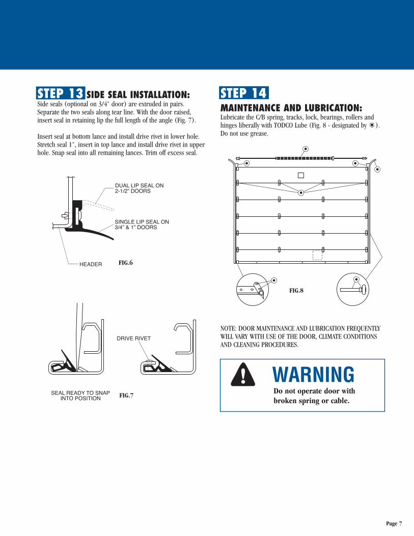
STEP 13 SIDE SEAL INSTALLATION:Side seals (optional on 3/4" door) are extruded in pairs.Separate the two seals along tear line. With the door raised,insert seal in retaining lip the full length of the angle (Fig. 7).
Insert seal at bottom lance and install drive rivet in lower hole.Stretch seal 1", insert in top lance and install drive rivet in upperhole. Snap seal into all remaining lances. Trim off excess seal.
WARNING
STEP 14MAINTENANCE AND LUBRICATION:Lubricate the C/B spring, tracks, lock, bearings, rollers andhinges liberally with TODCO Lube (Fig. 8 - designated by ).Do not use grease.
NOTE: DOOR MAINTENANCE AND LUBRICATION FREQUENTLYWILL VARY WITH USE OF THE DOOR, CLIMATE CONDITIONSAND CLEANING PROCEDURES.
Do not operate door withbroken spring or cable.
FIG.6
FIG.7
FIG.8
Page 7
For new orders and order Fornew orders and order inquiries:
call: (740) 383-6376
fax: 1-800-24-TODCO (800-248-6326)
A roll-up door is a large, heavy object that moves with the help of a spring that is under high tension. Since moving objects and springs under tension can cause injuries or death, your safety and the proper operation of the door depend on your doing the following:
BEFORE OPERATION1. Inspect all fasteners. Tighten or replace loose fasteners on lift handle, lock, pull
strap and hinges. 2. Inspect pull strap. Have frayed, worn or damaged strap replaced. Do not tie
anything to pull strap. Longer straps are available from TODCO.3. Do not operate door with a broken counterbalance spring. The door will not be
counterbalanced and will fall if opened. Have trained service person replacespring.
DURING OPERATION1. Check lock movement. Lubricate with light oil such as TODCO Lube (not grease)
if movement is stiff. Have worn or damaged lock replaced.2. Keep three limbs in contact with vehicle (2 hands and 1 foot, or 2 feet and 1
hand) when climbing in or out. Do not use the pull strap to help you get in or out.3. Check door movement. If door is hard to move, lubricate rollers, counterbalance
spring and bearings, and hinges with TODCO Lube. Have damaged or wornrollers and hinges replaced. If door is still hard to move, have a trained serviceperson check it. Do not try to adjust or repair the spring or counterbalanceassembly.
4. Check cable attachment. Have frayed, damaged or worn cables replaced. Cabledrums should be snug against bearing. Have trained service person replacecables and adjust cable drums.
5. Make sure tracks and door opening are not blocked. Do not stand in or walkthrough doorway when door is moving.
AFTER OPERATION1. Close and lock door before driving vehicle.
MAINTENANCE1. Do not attach anything to, or modify door. Use genuine TODCO parts for
replacements.2. High pressure wash or harsh cleaning solutions can damage paint.3. Have worn or faded warning stickers replaced. Do not paint over warning stickers.
SAFETY INSTRUCTIONS
Safety warning sticker not shown actual size.
WARNINGHigh-tension spring cancause severe injury or death.Repairs and adjustmentsmust be made by trainedservice personnel.
1. LOCATE STICKERS PROPERLY.A. Warning and safety instructions sticker on outside of
door bottom panel.B. Spring warning sticker on inside center of door panel.
2. REMOVE PREMASK.3. DO NOT PAINT OVER STICKERS.4. REPLACE WORN, FADED OR DAMAGED STICKERS.
1332 Fairground Rd. E.Marion, Ohio 43302Telephone (740) 383-6376
A Division of Overhead Door Corporation
Copyright 2015 ©TODCO, MARION, OHIO TODCO RESERVES THE RIGHT TO CHANGE PRODUCT SPECIFICATIONS AT ANY TIME WITHOUT NOTICE.
For assistance, contact your TODCOrepresentative or plant at (740) 383-6376.
NOT JUST TOUGH…TODCO-TOUGH
www.todco.com
1332 Fairground Road EastMarion, Ohio 43302
(740) 383-6376
Related Documents


![A numerical study of diagonally split Runge–Kutta methods ... · Diagonally split Runge–Kutta (DSRK) time discretization meth-ods [1] are a class of implicit time-stepping schemes](https://static.cupdf.com/doc/110x72/5f0d2ee57e708231d43914a5/a-numerical-study-of-diagonally-split-rungeakutta-methods-diagonally-split.jpg)
