Page 1 THIS MANUAL MUST BE LEFT FOR FUTURE REFERENCE INSTALLATION INSTRUCTIONS LRP14G(E/X) / LRP14AC / LRP14HP UNITS RESIDENTIAL PACKAGED UNITS Gas/Electric – Air Conditioner – Heat Pump 508201-01 6/2021 Table of Contents Unit Dimensions ..........................................................2 Roof Curb Dimensions ................................................4 Adjustable Roof Curb Dimensions...............................6 Installation ...................................................................7 Venting.........................................................................9 Duct System ..............................................................10 Filters .........................................................................10 Condensate Drain...................................................... 11 Gas Piping ................................................................. 11 Electrical Wiring ........................................................12 Heating Start-Up .......................................................13 Operation – Gas / Electric Units ................................15 Maintenance – Gas / Electric Units ...........................16 Wiring Diagram – LRP14GE......................................18 LRP14AC / LRP14HP................................................19 Condensate Drain......................................................19 Sequence of Operation..............................................19 Maintenance – LRP14AC/LRP14HP .........................22 Wiring Diagrams – LRP14AC / LRP14HP .................24 ©2021 Lennox Industries Inc. Dallas, Texas, USA WARNING Improper installation, adjustment, alteration, service or maintenance can cause property damage, personal injury or loss of life. Installation and service must be performed by a licensed professional HVAC installer or equivalent, or service agency. IMPORTANT The Clean Air Act of 1990 bans the intentional venting of refrigerant (CFCs, HCFCs and HFCs) as of July 1, 1992. Approved methods of recovery, recycling or reclaiming must be followed. Fines and/or incarceration may be levied for noncompliance. CAUTION As with any mechanical equipment, contact with sharp sheet metal edges can result in personal injury. Take care while handling this equipment and wear gloves and protective clothing.

Welcome message from author
This document is posted to help you gain knowledge. Please leave a comment to let me know what you think about it! Share it to your friends and learn new things together.
Transcript
Page 1
THIS MANUAL MUST BE LEFT FOR FUTURE REFERENCE
INSTALLATION INSTRUCTIONSLRP14G(E/X) / LRP14AC / LRP14HP UNITSRESIDENTIAL PACKAGED UNITSGas/Electric – Air Conditioner – Heat Pump508201-016/2021
Table of ContentsUnit Dimensions ..........................................................2Roof Curb Dimensions ................................................4Adjustable Roof Curb Dimensions...............................6Installation ...................................................................7Venting.........................................................................9Duct System ..............................................................10Filters .........................................................................10Condensate Drain......................................................11Gas Piping .................................................................11Electrical Wiring ........................................................12Heating Start-Up .......................................................13Operation – Gas / Electric Units ................................15Maintenance – Gas / Electric Units ...........................16Wiring Diagram – LRP14GE......................................18LRP14AC / LRP14HP ................................................19Condensate Drain......................................................19Sequence of Operation..............................................19Maintenance – LRP14AC/LRP14HP .........................22Wiring Diagrams – LRP14AC / LRP14HP .................24
©2021 Lennox Industries Inc. Dallas, Texas, USA
WARNINGImproper installation, adjustment, alteration, service or maintenance can cause property damage, personal injury or loss of life. Installation and service must be performed by a licensed professional HVAC installer or equivalent, or service agency.
IMPORTANTThe Clean Air Act of 1990 bans the intentional venting of refrigerant (CFCs, HCFCs and HFCs) as of July 1, 1992. Approved methods of recovery, recycling or reclaiming must be followed. Fines and/or incarceration may be levied for noncompliance.
CAUTIONAs with any mechanical equipment, contact with sharp sheet metal edges can result in personal injury. Take care while handling this equipment and wear gloves and protective clothing.
Page 2
12.12
3.87
3.62
4.06
26.19
32.20
POWER ENTRY1-1/8 DIA. KNOCKOUT
LOW VOLTAGE ENTRY7/8 KNOCKOUT
GAS ENTRY
5.863.07
6.20
17.07
13.4413.44
14.3216.06
6.20
40.8921.63
13.21
TYPICAL DRAINLOCATION
CONDENSATEDRAIN 3/4 NPT
5.753.55
4.12
TYPICALVENT HOOD
SIDE VIEWS
11.49
2.33
47.66
1.9816.77
2.48
14.02
47.66
POWER ENTRY
GAS ENTRY
6.94
2.33
11.4916.07
18.52
3.25
4.5620.3121.06
23.19
RETURNAIR
SUPPLYAIRTOP VIEW
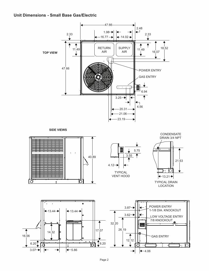
Unit Dimensions - Small Base Gas/Electric
Page 3
14.32
4.20
3.76
6.20
17.07
18.19 18.19
16.06
6.20
3.62
4.06
36.20
12.14
30.19
3.87 POWER ENTRY1-1/8 DIA. KNOCKOUT
LOW VOLTAGE ENTRY7/8 DIA. KNOCKOUT
GAS SUPPLY
44.8921.63
13.21
TYPICAL DRAINLOCATION
CONDENSATEDRAIN 3/4 NPT
5.753.55
4.12
TYPICALVENT HOOD
SIDE VIEWS
TOP VIEW
POWER ENTRY
GAS ENTRY
RETURNAIR
2.1119.49
2.39 2.33
11.4916.07
18.52
6.94
3.2510.06
19.49
SUPPLYAIR
25.8126.56
28.68
11.49
2.33
47.66
56.13
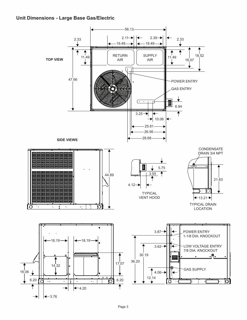
Unit Dimensions - Large Base Gas/Electric
Page 4
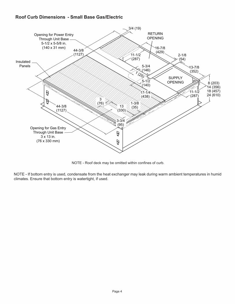
NOTE - Roof deck may be omitted within confines of curb.
InsulatedPanels
Opening for Power EntryThrough Unit Base
5-1/2 x 5-5/8 in.(140 x 31 mm)
Opening for Gas EntryThrough Unit Base
3 x 13 in.(76 x 330 mm)
44-3/8(1127)
44-3/8(1127)
16-7/8(429)
13-7/8(352)
2-1/8(54)
11-1/2(287)
SUPPLYOPENING
RETURNOPENING
8 (203)14 (356)18 (457)24 (610)
3/4 (19)
1 (25)5-1/2(140)
5-3/4(146)
11-1/2(287)
17-1/4(438)
1-3/8(35)
3-3/4(95)
13(330)
3(76)
NOTE - If bottom entry is used, condensate from the heat exchanger may leak during warm ambient temperatures in humid climates. Ensure that bottom entry is watertight, if used.
Roof Curb Dimensions - Small Base Gas/Electric
Page 5
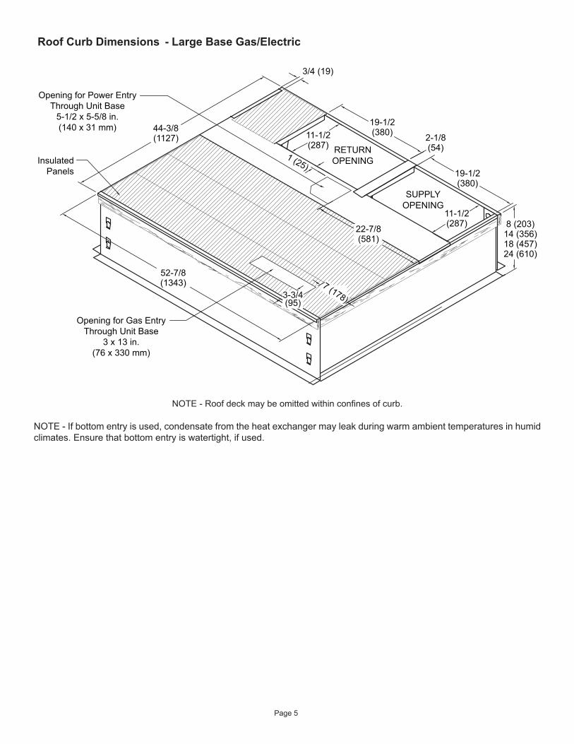
NOTE - Roof deck may be omitted within confines of curb.
InsulatedPanels
Opening for Power EntryThrough Unit Base
5-1/2 x 5-5/8 in.(140 x 31 mm)
Opening for Gas EntryThrough Unit Base
3 x 13 in.(76 x 330 mm)
52-7/8(1343)
44-3/8(1127)
19-1/2(380)
11-1/2(287)
19-1/2(380)
2-1/8(54)
11-1/2(287)
SUPPLYOPENING
RETURNOPENING
8 (203)14 (356)18 (457)24 (610)
3-3/4(95)
22-7/8(581)
7 (178)
3/4 (19)
1 (25)
NOTE - If bottom entry is used, condensate from the heat exchanger may leak during warm ambient temperatures in humid climates. Ensure that bottom entry is watertight, if used.
Roof Curb Dimensions - Large Base Gas/Electric
Page 6
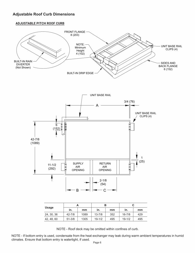
A
B C
3/4 (76)
6(152)
1(25)
11-1/2(292)
42-7/8(1089)
SUPPLYAIR
OPENING
RETURNAIR
OPENING
2-1/8(54)
UNIT BASE RAIL
BUILT-IN DRIP EDGE
BUILT-IN RAINDIVERTER(Not Shown)
FRONT FLANGE8 (203)
SIDES ANDBACK FLANGE
6 (152)
UNIT BASE RAILCLIPS (4)
NOTE:Minimum
Height4 (102)
UNIT BASE RAILCLIPS (4)
ADJUSTABLE PITCH ROOF CURB
UsageA B C
in. mm in. mm in. mm24, 30, 36 42-7/8 1089 13-7/8 352 16-7/8 42942, 48, 60 51-3/8 1305 19-1/2 495 19-1/2 495
NOTE - Roof deck may be omitted within confines of curb.
NOTE - If bottom entry is used, condensate from the heat exchanger may leak during warm ambient temperatures in humid climates. Ensure that bottom entry is watertight, if used.
Adjustable Roof Curb Dimensions
Page 7
InstallationThese instructions must be saved for future reference.
These units are single package air conditioners with gas heat designed for outdoor installation on a rooftop or a slab.
The units are completely assembled. All piping, refrigerant charge, and electrical wiring are factory installed and tested. The units require only electric power, gas piping, condensate drain, and duct connections, plus installation of the vent cover at the point of installation.
If components are to be added to a unit to meet local codes, they are to be installed at the dealer’s and/or customer’s expense.
The size of unit for the proposed installation should be based on heat loss/heat gain calculation made according to the methods of Air Conditioning Contractors of America (ACCA).
In the State of Massachusetts:This product must be installed by a licensed Plumber or Gas Fitter. When flexible connectors are used, the maximum length shall not exceed 36”. When lever-type gas shutoffs are used, they shall be T-handle type.
WARNING
These installation instructions are intended as a general guide only, for use by an experienced, qualified contractor.
These units are certified by E.T.L. Testing Laboratories, Inc.:
• For use as a forced air furnace with cooling unit.• For outdoor installation only.• For installation on combustible material.• For use with natural gas or propane gas. (Conversion
kit required for propane gas application.)
These units are not suitable for use with conventional venting systems.
InspectionAs soon as the unit is received, it should be inspected for possible damage during transit. If damage is evident, the extent of the damage should be noted on the carrier’s freight bill. A separate request for inspection by the carrier’s agent should be made in writing.
LocationUse the following guidelines to select a suitable location for these units.
1. Unit is designed for outdoor installation only. Unit must be installed so all electrical components are protected from water.
2. Condenser coils must have an unlimited supply of air.3. For ground level installation, use a level prefabricated
pad or use a level concrete slab. Do not tie the slab to the building foundation.
4. Maintain level within a tolerance of 1/4” maximum across the entire length or width of the unit.
Unit levelness is critical for proper float switch operation.
CAUTION
5. Do not locate the unit where the combustion air supply will be exposed to any of the following substances:
• Permanent wave solutions• Chlorinated waxes and cleaners• Chlorine-based swimming pool chemicals• Water softening chemicals• Deicing salts or chemicals• Carbon tetrachloride• Halogen-type refrigerants• Cleaning solvents (such as perchloroethylene)• Printing inks, paint removers, varnishes, etc.• Cements and glues• Antistatic fabric softeners for clothes dryers• Masonry acid washing materials• Chlorinated laundry products• Hydrochloric acid
Use of Unit During ConstructionUse of this unit as a construction heater or air conditioner is not recommended during any phase of construction. Very low return air temperatures, harmful vapors and operation of the unit with clogged or misplaced filters will damage the unit.
If this unit has been used for heating or cooling of buildings or structures under construction, the following conditions must be met or the warranty will be void:
• A room thermostat must control the unit. The use of fixed jumpers that will provide continuous heating or cooling is not allowed.
• A pre-filter must be installed at the entry to the return air duct.
• The return air duct must be provided and sealed to the unit.
Page 8
• Return air temperature range between 55°F (13°C) and 80°F (27°C) must be maintained.
• Air filters must be replaced and pre-filters must be removed upon construction completion.
• The input rate and temperature rise must be set per the unit rating plate.
• The heat exchanger, components, duct system, air filters and evaporator coil must be thoroughly cleaned following final construction clean-up.
• The unit operating conditions (including airflow, cooling operation, ignition, input rate, temperature rise and venting) must be verified according to these installation instructions.
ClearancesAll units require certain clearances for proper operation and service. Refer to Table 1 for the minimum clearances to combustibles, servicing, and proper unit operation. In the U.S., units may be installed on combustible floors made from wood or class A, B, or C roof covering material. In Canada, units may be installed on combustible floors. Units must be installed outdoors.
Clearance to combustibles below the unit flue is 10 inches since the flue points down.
Do not permit overhanging structures or shrubs to obstruct condenser air discharge outlet, combustion air inlet, or vent outlet.
Clearance to Combustibles
Clearance for Service Access
Front of unit 0 in. 24 in.Back of unit 0 in. 0 in.Left side 0 in. 24 in.
Right side (from vent hood) 12 in. 24 in.
Base of unit 0 in. 0 in.Top of unit 0 in. 48 in.
Minimum clearance to combustible material below the flue is 10 inches to allow proper dissipation of flue gasses and temperatures. For any future service, installer must provide access to screws of top and rear panels.
Table 1. Minimum Clearances
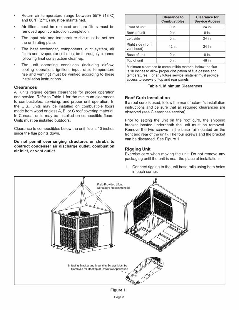
Roof Curb InstallationIf a roof curb is used, follow the manufacturer’s installation instructions and be sure that all required clearances are observed (see Clearances section).
Prior to setting the unit on the roof curb, the shipping bracket located underneath the unit must be removed. Remove the two screws in the base rail (located on the front and rear of the unit). The four screws and the bracket can be discarded. See Figure 1.
Rigging UnitExercise care when moving the unit. Do not remove any packaging until the unit is near the place of installation.
1. Connect rigging to the unit base rails using both holes in each corner.
Shipping Bracket and Mounting Screws Must be Removed for Rooftop or Downflow Application
Field-Provided LiftingSpreaders Recommended
Figure 1.
Page 9
VentingThe vent outlet must be installed in a location as to prevent building degradation and must be consistent with the National Fuel Gas Code, Z223.1 or CAN/CGA-B149.1 & .2.
The products of combustion are discharged through a screened opening on the gas heat side panel. The horizontal vent system shall terminate at least 4 feet below, 4 feet horizontally from, or 1 foot above any door, window, or gravity air inlet into the building. The vent system shall terminate at least 3 feet above any forced air inlet located within 10 feet.
The unit shall be installed in a manner such that snow accumulation will not restrict the flow of flue products.
Minimum horizontal clearance of 4 feet from electric meters, gas meters, regulator, and relief equipment is required.
In addition to the above requirements, consideration must be given to prevent unwanted ice buildup from the vent condensate. The vent should not be located on the side of a building where the prevailing winter winds could trap the moisture, causing it to freeze on the walls or on overhangs (under eaves). The vent should not be located over a sidewalk, patio, or other walkway where the condensate could cause the surface to become slippery.
The products of combustion must not be allowed to accumulate within a confined space where they may be recirculated.
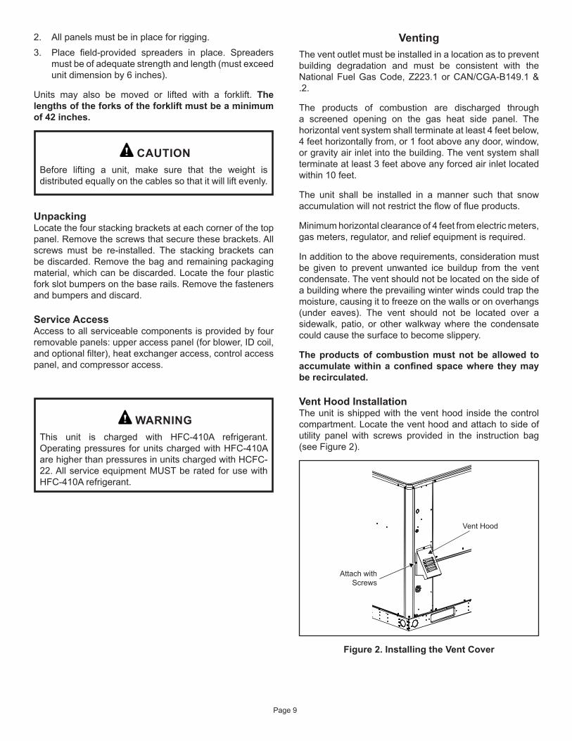
Vent Hood InstallationThe unit is shipped with the vent hood inside the control compartment. Locate the vent hood and attach to side of utility panel with screws provided in the instruction bag (see Figure 2).
Vent Hood
Attach withScrews
Figure 2. Installing the Vent Cover
2. All panels must be in place for rigging.3. Place field-provided spreaders in place. Spreaders
must be of adequate strength and length (must exceed unit dimension by 6 inches).
Units may also be moved or lifted with a forklift. The lengths of the forks of the forklift must be a minimum of 42 inches.
Before lifting a unit, make sure that the weight is distributed equally on the cables so that it will lift evenly.
CAUTION
UnpackingLocate the four stacking brackets at each corner of the top panel. Remove the screws that secure these brackets. All screws must be re-installed. The stacking brackets can be discarded. Remove the bag and remaining packaging material, which can be discarded. Locate the four plastic fork slot bumpers on the base rails. Remove the fasteners and bumpers and discard.
Service AccessAccess to all serviceable components is provided by four removable panels: upper access panel (for blower, ID coil, and optional filter), heat exchanger access, control access panel, and compressor access.
This unit is charged with HFC-410A refrigerant. Operating pressures for units charged with HFC-410A are higher than pressures in units charged with HCFC-22. All service equipment MUST be rated for use with HFC-410A refrigerant.
WARNING
Page 10
If an existing gas furnace is being removed from a common venting system when this packaged unit is installed, then read and follow the instructions in the “Removal of Unit from Common Venting System” section that follows. Otherwise, you may skip this section.
NOTE:
Removal of Unit from Common Venting SystemWhen an existing furnace is removed from a common venting system serving other appliances, the venting system is likely to be too large to properly vent the remaining attached appliances. The following test should be conducted with each appliance while the other appliances connected to the common venting system are not in operation.
1. Seal any unused openings in the common venting system.
2. Visually inspect the venting system for proper size and horizontal pitch and determine there is no blockage or restriction, leakage, corrosion, or other deficiencies which could cause an unsafe condition.
3. Insofar as is practical, close all building doors and windows between the space in which the appliances remaining connected to the common venting system are located and other spaces in the building. Turn on clothes dryers and any appliance not connected to the common venting system. Turn on exhaust fans, such as range hoods and bathroom exhausts, so they will operate at maximum speed. Do not operate a summer exhaust fan. Close fireplace dampers.
4. Following the lighting instructions, place the unit being inspected in operation. Adjust the thermostat so the appliance will operate continuously.
5. Test for spillage at the draft control relief opening after 5 minutes of main burner operation. Use the flame of a match or candle.
6. Follow the preceding steps for each appliance connected to the common venting system.
7. After it has been determined that each appliance remaining connected to the common venting system properly vents when tested as outlined above, return doors, windows, exhaust fans, fireplace dampers, and any other fuel burning appliance to their previous condition of use.
8. If improper venting is observed during any of the above tests, the common venting system must be corrected. See National Fuel Gas Code, ANSI Z223.1 (latest edition) or CAN/CGA B149.1 & .2 Canadian Installation Codes to correct improper operation of common venting system.
Duct SystemThe duct system should be designed and sized according to the methods in the Air Conditioning Contractors of America (ACCA) manual that is most appropriate to the installation application.
A closed return air duct system shall be used. This shall not preclude use of economizers or outdoor fresh air intake. It is recommended that supply and return air duct connections at the unit be made with flexible joints.
The supply and return air duct systems should be designed for the CFM and static requirements of the job. They should not be sized by matching the dimensions of the duct connections on the unit.
The unit is shipped ready for horizontal flow (side duct connections) or downflow (bottom duct connections). All units are equipped with a drain pan overflow switch that is installed and wired at the factory. Duct attachment screws are intended to go into the duct panel flanges. Duct to unit connections must be sealed and weather proofed.
For horizontal duct systems:1. Remove the duct covers on side of the unit. They can
be discarded.2. Install the duct system to the unit.
For downflow duct systems:1. Remove the duct covers on side of the unit. Keep the
screws and the covers as they will be re-installed later.2. Remove the downflow duct covers located inside unit.
Remove the four screws securing each cover. Remove the covers from the unit. They can be discarded.
3. Remove screws located between the supply and return air openings that attach the blower deck to the base pan. These screws can interfere with bottom duct connections or roof curb seals. Discard these screws.
4. Install the duct system to the unit.5. Re-install the duct covers removed in Step 1.
FiltersAir filters are not supplied with the unit. A field-provided air filter must always be installed ahead of the evaporator coil and must be cleaned or replaced if necessary. Dirty filters will reduce the airflow of the unit.
An optional filter rack kit may be purchased separately for installation inside the unit’s coil compartment. Air filter sizes are shown in Table 2 for use with filter rack kit.
The filter rack must be installed prior to installation of the unit in applications where access to the rear panel is limited.
NOTE:
Page 11
Gas PipingProper sizing of a gas piping depends on the cubic feet per hour of gas flow required, specific gravity of the gas, and length of run. National Fuel Gas Code Z223.1 latest edition should be followed in all cases unless superseded by local codes or gas company requirements. In Canada, refer to CAN/CGA B.149.1 & .2 (latest edition).
The heating value of the gas may differ with locality. The value should be checked with the local gas utility. For temperature rise of unit, see unit rating plate.
Gas Piping Recommendations• A drip leg and a ground joint union must be installed in
the gas piping. A ground joint union is recommended by the manifold/valve.
• When required by local codes, a manual shutoff valve may have to be installed outside of the unit.
• Use pipe thread sealing compound resistant to propane gas sparingly on male threads.
• The gas supply should be a separate line and installed in accordance with all safety codes listed on Page 1. After the gas connections have been completed, open the main shutoff valve admitting normal gas pressure to the mains. Check all joints for leaks with soapy solution or other material suitable for the purpose.
Never use a flame to check for gas leaks. Explosion causing injury or death may occur.
WARNING
• The furnace and its field supplied manual shutoff valve must be disconnected from the gas supply piping system during any pressure testing of that system at test pressures in excess of 1/2 PSIG (3.48kPa).
• A 1/8” N.P.T. plugged tapping, accessible for test gauge connections, must be installed immediately upstream of the gas supply connection to the furnace.
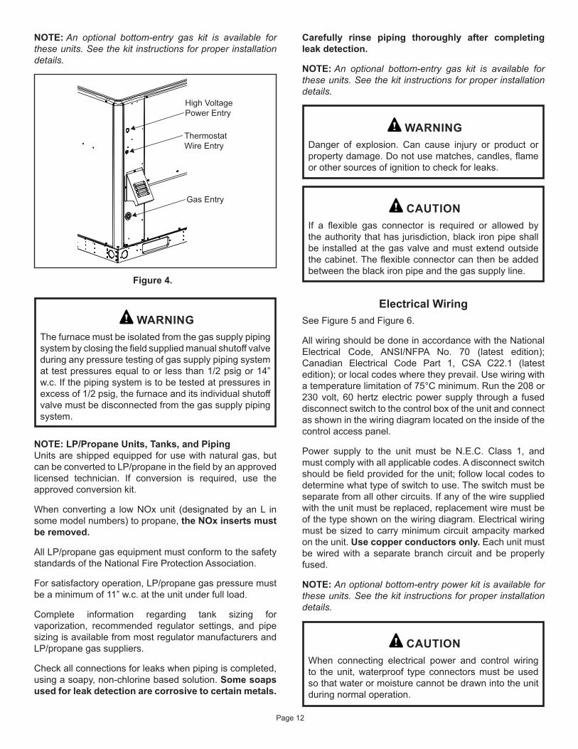
Gas ConnectionThe gas supply line is routed through the gas entry location on the side of the unit (see Figure 4). A grommet is provided in the instruction bag and should be used to seal gas supply line to gas entry of control compartment.
Table 2. Unit Air Filter Sizes - inches
Unit Model Filter 1 Filter 2
24, 30, 36 14 x 20 x 120 x 20 x 1
42, 48, 60 20 x 20 x 1
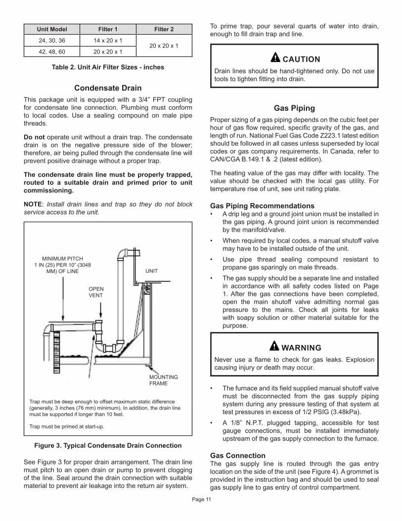
Condensate DrainThis package unit is equipped with a 3/4” FPT coupling for condensate line connection. Plumbing must conform to local codes. Use a sealing compound on male pipe threads.
Do not operate unit without a drain trap. The condensate drain is on the negative pressure side of the blower; therefore, air being pulled through the condensate line will prevent positive drainage without a proper trap.
The condensate drain line must be properly trapped, routed to a suitable drain and primed prior to unit commissioning.
NOTE: Install drain lines and trap so they do not block service access to the unit.
Figure 3. Typical Condensate Drain Connection
MINIMUM PITCH 1 IN (25) PER 10” (3048
MM) OF LINE
OPEN VENT
UNIT
MOUNTING FRAME
Trap must be deep enough to offset maximum static difference (generally, 3 inches (76 mm) minimum). In addition, the drain line must be supported if longer than 10 feet.
Trap must be primed at start-up.
See Figure 3 for proper drain arrangement. The drain line must pitch to an open drain or pump to prevent clogging of the line. Seal around the drain connection with suitable material to prevent air leakage into the return air system.
To prime trap, pour several quarts of water into drain, enough to fill drain trap and line.
Drain lines should be hand-tightened only. Do not use tools to tighten fitting into drain.
CAUTION
Page 12
NOTE: An optional bottom-entry gas kit is available for these units. See the kit instructions for proper installation details.
ThermostatWire Entry
High VoltagePower Entry
Gas Entry
Figure 4.
The furnace must be isolated from the gas supply piping system by closing the field supplied manual shutoff valve during any pressure testing of gas supply piping system at test pressures equal to or less than 1/2 psig or 14” w.c. If the piping system is to be tested at pressures in excess of 1/2 psig, the furnace and its individual shutoff valve must be disconnected from the gas supply piping system.
WARNING
NOTE: LP/Propane Units, Tanks, and Piping Units are shipped equipped for use with natural gas, but can be converted to LP/propane in the field by an approved licensed technician. If conversion is required, use the approved conversion kit.
When converting a low NOx unit (designated by an L in some model numbers) to propane, the NOx inserts must be removed.
All LP/propane gas equipment must conform to the safety standards of the National Fire Protection Association.
For satisfactory operation, LP/propane gas pressure must be a minimum of 11” w.c. at the unit under full load.
Complete information regarding tank sizing for vaporization, recommended regulator settings, and pipe sizing is available from most regulator manufacturers and LP/propane gas suppliers.
Check all connections for leaks when piping is completed, using a soapy, non-chlorine based solution. Some soaps used for leak detection are corrosive to certain metals.
Electrical Wiring See Figure 5 and Figure 6.
All wiring should be done in accordance with the National Electrical Code, ANSI/NFPA No. 70 (latest edition); Canadian Electrical Code Part 1, CSA C22.1 (latest edition); or local codes where they prevail. Use wiring with a temperature limitation of 75°C minimum. Run the 208 or 230 volt, 60 hertz electric power supply through a fused disconnect switch to the control box of the unit and connect as shown in the wiring diagram located on the inside of the control access panel.
Power supply to the unit must be N.E.C. Class 1, and must comply with all applicable codes. A disconnect switch should be field provided for the unit; follow local codes to determine what type of switch to use. The switch must be separate from all other circuits. If any of the wire supplied with the unit must be replaced, replacement wire must be of the type shown on the wiring diagram. Electrical wiring must be sized to carry minimum circuit ampacity marked on the unit. Use copper conductors only. Each unit must be wired with a separate branch circuit and be properly fused.
NOTE: An optional bottom-entry power kit is available for these units. See the kit instructions for proper installation details.
When connecting electrical power and control wiring to the unit, waterproof type connectors must be used so that water or moisture cannot be drawn into the unit during normal operation.
CAUTION
Carefully rinse piping thoroughly after completing leak detection.
NOTE: An optional bottom-entry gas kit is available for these units. See the kit instructions for proper installation details.
Danger of explosion. Can cause injury or product or property damage. Do not use matches, candles, flame or other sources of ignition to check for leaks.
WARNING
If a flexible gas connector is required or allowed by the authority that has jurisdiction, black iron pipe shall be installed at the gas valve and must extend outside the cabinet. The flexible connector can then be added between the black iron pipe and the gas supply line.
CAUTION

Page 13
Figure 5. 208/230 Line Voltage Wiring
SIN
GLE
PH
ASE
POW
ER S
UPP
LY
GROUND LUG
CONTACTORFIELD-SUPPLIED FUSED OR CIRCUIT BREAKER
DISCONNECT
If 208 Volt is supplied, transformer connection must be changed
Figure 6. Typical Wiring Connections
R
G
W
Y1
C
R
G
W
Y1
C
THERMOSTAT OUTDOOR UNIT
Red
Blue
Yellow
White
Green
!C
AUTI
ON
requ
ired
by th
e in
door
ther
mos
tat.
Ref
er to
the
ther
mos
tat i
nsta
llatio
n in
stru
ctio
ns.
Do
not c
onne
ctco
nnec
tions
exc
ept w
hen
C
SINGLE PHASE
L2 L1GROUNDSCREW
POWER WIRING208/230-1-60
(75° MIN. WIRE)POWER WIRING
24V CONTROL WIRING(NEC CLASS 2)
ThermostatThe room thermostat should be located on an inside wall where it will not be subject to drafts, sun exposure, or heat from electrical fixtures or appliances. Follow the manufacturer’s instructions enclosed with thermostat for general installation procedure. Color-coded insulated wires (#18 AWG) should be used to connect the thermostat to the unit.
Heating Start-Up For Your Safety, Read Before Lighting
Furnace is equipped with a direct ignition control. Do not attempt to manually light the burners.
CAUTION
Pre-Start ChecklistComplete the following checks before starting the unit:1. Check the type of gas being supplied. Be sure it is the
same as listed on the unit nameplate.2. Make sure that the vent cover has been properly
installed.
To Light Main Burners1. Turn off electrical power to unit.2. Turn the thermostat to lowest setting.3. Slide the gas valve switch to the “ON” position (see
Figure 7).4. Turn on electrical power to the unit.5. Set the room thermostat to the desired temperature.
(If the thermostat “set” temperature is above room temperature after the pre-purge time expires, main burners will light.)
Regulator Adjustment
Figure 7. Gas Valve
Four wires are required for cooling. The heat anticipator setting is 0.75 amp.
CompressorUnits are shipped with compressor mountings factory-adjusted and ready for operation.
Do not loosen compressor mounting bolts.
CAUTION
Page 14
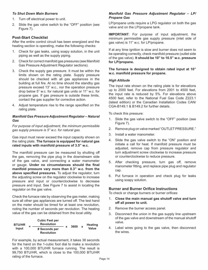
To Shut Down Main Burners1. Turn off electrical power to unit.2. Slide the gas valve switch to the “OFF” position (see
Figure 7).
Post-Start ChecklistAfter the entire control circuit has been energized and the heating section is operating, make the following checks:1. Check for gas leaks, using soapy solution, in the unit
piping as well as the supply piping.2. Check for correct manifold gas pressures (see Manifold
Gas Pressure Adjustment Regulator sections).3. Check the supply gas pressure. It must be within the
limits shown on the rating plate. Supply pressure should be checked with all gas appliances in the building at full fire. At no time should the standby gas pressure exceed 13” w.c., nor the operation pressure drop below 5” w.c. for natural gas units or 11” w.c. for propane gas. If gas pressure is outside these limits, contact the gas supplier for corrective action.
4. Adjust temperature rise to the range specified on the rating plate.
Manifold Gas Pressure Adjustment Regulator – Natural GasFor purpose of input adjustment, the minimum permissible gas supply pressure is 5” w.c. for natural gas.
Gas input must never exceed the input capacity shown on the rating plate. The furnace is equipped for natural gas rated inputs with manifold pressure of 3.5” w.c.
The manifold pressure can be measured by shutting off the gas, removing the pipe plug in the downstream side of the gas valve, and connecting a water manometer or gauge. Under no circumstances should the final manifold pressure vary more than 0.3” w.c. from the above specified pressures. To adjust the regulator, turn the adjusting screw on the regulator clockwise to increase pressure and input or counterclockwise to decrease pressure and input. See Figure 7 to assist in locating the regulator on the gas valve.
Check the furnace rate by observing the gas meter, making sure all other gas appliances are turned off. The test hand on the meter should be timed for at least one revolution, noting the number of seconds per revolution. The heating value of the gas can be obtained from the local utility.
BTU/HR Input =
Cubic Feet per Revolution
x 3600 x Heating Value# Seconds per
Revolution
For example, by actual measurement, it takes 38 seconds for the hand on the 1-cubic foot dial to make a revolution with a 100,000 BTU/HR furnace running. The result is 99,750 BTU/HR, which is close to the 100,000 BTU/HR rating of the furnace.
Manifold Gas Pressure Adjustment Regulator – LP/Propane GasLP/propane units require a LPG regulator on both the gas valve and on the LP/propane tank.
IMPORTANT: For purpose of input adjustment, the minimum permissible gas supply pressure (inlet side of gas valve) is 11” w.c. for LP/propane.
If at any time ignition is slow and burner does not seem to be operating correctly, check manifold pressure (outlet side of the gas valve). It should be 10” to 10.5” w.c. pressure for LP/propane.
The furnace is designed to obtain rated input at 10” w.c. manifold pressure for propane.
High AltitudeThe input rate shown on the rating plate is for elevations up to 2000 feet. For elevations from 2001 to 4500 feet, the input rate is reduced by 5%. For elevations above 4500 feet, refer to the National Fuel Gas Code Z223.1 (latest edition) or the Canadian Installation Codes CAN/CGA-B149.1 & B149.2 for further details.
To check this pressure:1. Slide the gas valve switch to the “OFF” position (see
Figure 7).2. Remove plug on valve marked “OUTLET PRESSURE.”3. Install a water manometer.4. Slide the gas valve switch to the “ON” position and
initiate a call for heat. If manifold pressure must be adjusted, remove cap from pressure regulator and turn adjustment screw clockwise to increase pressure or counterclockwise to reduce pressure.
5. After checking pressure, turn gas off, remove manometer fitting, and replace pipe plug and regulator cap.
6. Put furnace in operation and check plug for leaks using soapy solution.
Burner and Burner Orifice InstructionsTo check or change burners or burner orifices:1. Close the main manual gas shutoff valve and turn
off all power to unit.2. Remove the burner access panel. 3. Disconnect the union in the gas supply line upstream
of the gas valve and downstream of the manual shutoff valve.
4. Label wires going to the gas valve, then disconnect the wires.
Page 15
A combustion air inducer operates for the first 10 seconds of every cooling cycle to prevent insects from nesting in the flue outlet.
Blower Delay – CoolingThe circulating air blower is controlled by a timing circuit in the integrated blower/ignition control. Timings are not adjustable. Blower “ON” delay is 5 seconds after the compressor starts and blower “OFF” timing is 60 seconds after the compressor shuts down.
NOTE: There is no blower OFF delay when there is a call for G (fan only).
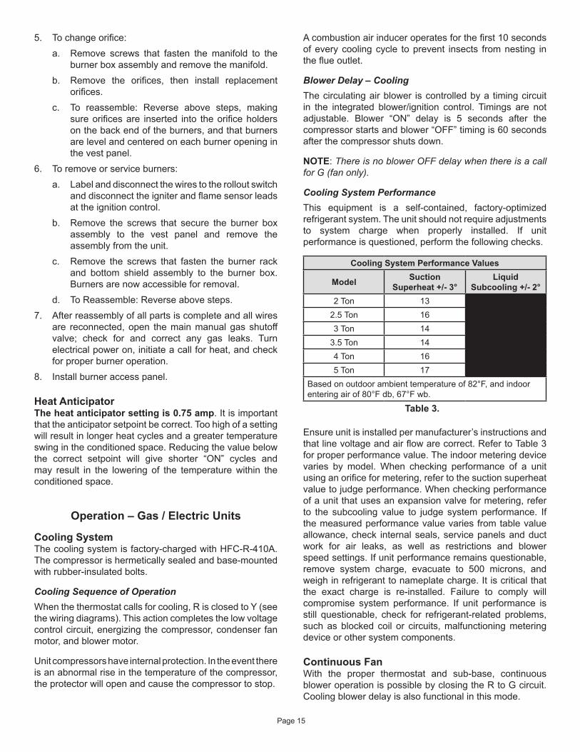
Cooling System PerformanceThis equipment is a self-contained, factory-optimized refrigerant system. The unit should not require adjustments to system charge when properly installed. If unit performance is questioned, perform the following checks.
Cooling System Performance Values
Model Suction Superheat +/- 3°
Liquid Subcooling +/- 2°
2 Ton 132.5 Ton 163 Ton 14
3.5 Ton 144 Ton 165 Ton 17
Based on outdoor ambient temperature of 82°F, and indoor entering air of 80°F db, 67°F wb.
Table 3.
Ensure unit is installed per manufacturer’s instructions and that line voltage and air flow are correct. Refer to Table 3 for proper performance value. The indoor metering device varies by model. When checking performance of a unit using an orifice for metering, refer to the suction superheat value to judge performance. When checking performance of a unit that uses an expansion valve for metering, refer to the subcooling value to judge system performance. If the measured performance value varies from table value allowance, check internal seals, service panels and duct work for air leaks, as well as restrictions and blower speed settings. If unit performance remains questionable, remove system charge, evacuate to 500 microns, and weigh in refrigerant to nameplate charge. It is critical that the exact charge is re-installed. Failure to comply will compromise system performance. If unit performance is still questionable, check for refrigerant-related problems, such as blocked coil or circuits, malfunctioning metering device or other system components.
Continuous FanWith the proper thermostat and sub-base, continuous blower operation is possible by closing the R to G circuit. Cooling blower delay is also functional in this mode.
5. To change orifice:a. Remove screws that fasten the manifold to the
burner box assembly and remove the manifold.b. Remove the orifices, then install replacement
orifices.c. To reassemble: Reverse above steps, making
sure orifices are inserted into the orifice holders on the back end of the burners, and that burners are level and centered on each burner opening in the vest panel.
6. To remove or service burners:a. Label and disconnect the wires to the rollout switch
and disconnect the igniter and flame sensor leads at the ignition control.
b. Remove the screws that secure the burner box assembly to the vest panel and remove the assembly from the unit.
c. Remove the screws that fasten the burner rack and bottom shield assembly to the burner box. Burners are now accessible for removal.
d. To Reassemble: Reverse above steps.7. After reassembly of all parts is complete and all wires
are reconnected, open the main manual gas shutoff valve; check for and correct any gas leaks. Turn electrical power on, initiate a call for heat, and check for proper burner operation.
8. Install burner access panel.
Heat Anticipator The heat anticipator setting is 0.75 amp. It is important that the anticipator setpoint be correct. Too high of a setting will result in longer heat cycles and a greater temperature swing in the conditioned space. Reducing the value below the correct setpoint will give shorter “ON” cycles and may result in the lowering of the temperature within the conditioned space.
Operation – Gas / Electric Units
Cooling SystemThe cooling system is factory-charged with HFC-R-410A. The compressor is hermetically sealed and base-mounted with rubber-insulated bolts.
Cooling Sequence of OperationWhen the thermostat calls for cooling, R is closed to Y (see the wiring diagrams). This action completes the low voltage control circuit, energizing the compressor, condenser fan motor, and blower motor.
Unit compressors have internal protection. In the event there is an abnormal rise in the temperature of the compressor, the protector will open and cause the compressor to stop.
Page 16
Heating Sequence of OperationWhen the thermostat calls for heating, R is closed to W. The following describes the gas heating sequence of operation.1. A call for heat from the room thermostat starts the
combustion air blower and the circulating air blower.2. When the speed of the combustion air blower reaches
proper RPM, the pressure switch closes, initiating a pre-purge period (30 seconds nominal).
3. When the pre-purge period has expired, the ignition control energizes the main gas valve and spark electrode for a period of 10 seconds.
4. If the flame sensor does not sense that a flame has been established in the 10-second interval, then the ignition control will de-energize the gas valve, and begins a 30 second inter-purge period, then initiates another trial for ignition.
5. The ignition control is designed to repeat this “trial for ignition” a total of three times. If, at the end of the third trial, flame still has not been established, then the ignition control will try to light again 1 hour later. The 1-hour retry is indefinite. The ignition control can be reset by interrupting the unit power or the thermostat circuit.
6. Once flame sense has been established, the circulating air blower is energized after a 30 second blower on delay.
7. When the thermostat is satisfied, the combustion air blower and gas valve are de-energized. The circulation air blower will continue to run for a short period after the furnace is shut down.
Blower Delay – Heating• The circulating air blower “OFF” delay is 120 seconds
after shutting down the burners. This delay is not adjustable.
• The circulating air blower “ON” delay is 120 seconds after “W” signal is received to allow the furnace to warm up.
Safety ControlsThe control circuit includes the following safety controls:
Limit ControlThis control is located behind the heat exchanger access panel and is designed to open at abnormally high circulating air temperatures. It resets automatically. The limit control operates when a high temperature condition, caused by inadequate airflow, occurs. This closes the main gas valve.
Pressure SwitchIf the combustion air blower should fail, the pressure switch prevents the spark electrode and gas valve from being energized.
Maintenance – Gas / Electric UnitsPeriodic inspection and maintenance normally consists of changing or cleaning the filters and cleaning the evaporator coil. On occasion, other components of the furnace may also require cleaning.
Shut off all electrical power to the unit before conducting any maintenance procedures. Failure to do so could cause personal injury.
WARNING
FiltersFilters are not supplied with the unit. Inspect once a month. Replace disposable or clean permanent type as necessary. Do not replace permanent type with disposable.
MotorsIndoor and outdoor fan and vent motors are permanently lubricated and require no maintenance.
Evaporator CoilDirt and debris should not be allowed to accumulate on the evaporator coil surface or other parts in the air circuit. Cleaning should be as often as necessary to keep coil clean. Use a brush, vacuum cleaner attachment, or other suitable means. If water is used to clean the coil, be sure the power to unit is shut off prior to cleaning. Care should be used when cleaning the coil so that the coil fins are not damaged.
Do not permit the hot condenser air discharge to be obstructed by overhanging structures or shrubs.
Condenser CoilClean condenser coil annually with water and inspect monthly during the cooling season.
Flame SensorIf the ignition control does not receive a signal from the flame sensor indicating that the burners have established flame, the gas valve closes after the 10-second trial for ignition period.
Rollout SwitchThe switch is located on the top of the burner box. In the event of a sustained main burner rollout, the rollout switch shuts off the ignition control and closes the main gas valve. To reset, push the button on top of the switch.
Secure Owner’s ApprovalWhen the system is functioning properly, secure the owner’s approval. Show the owner the location of all disconnect switches and the thermostat. Instruct the owner on how to start and stop the unit and how to adjust temperature settings within the limitations of the system.
Page 17
Condenser coil may need to be cleaned at startup in case oil from the manufacturing process is found on the condenser coil.
BurnersTo clean the burners, first remove them from the furnace as explained in the Burner and Burner Orifice Instructions section. Vacuum and/or brush as required.
Vent OutletVisually inspect vent outlet periodically to make sure that there is no buildup of soot or dirt. If necessary, clean to maintain adequate opening to discharge flue products.
Heat ExchangerWith proper combustion adjustment, the heat exchanger of a gas-fired furnace will seldom need cleaning. Sooting of a gas appliance is highly irregular and once cleaned, the cause of the sooting must be determined. If the heat exchanger should become sooted, it can be cleaned as follows:1. Remove the burner assembly as outlined in the Burner
and Burner Orifice Instructions section.2. Remove the combustion blower.3. At the bottom of the heating section, remove the screws
holding the flue collector box. Carefully remove the flue collector box without ripping the adjacent insulation.
4. Using a wire brush on a flexible wand, brush out the inside of each heat exchanger from the burner inlet and flue outlet ends.
5. Brush out the inside of the flue collector box.6. Run the wire brush down the heat exchanger tubes
from the flue collector end.7. If soot buildup is excessive, remove the vent motor and
clean the wheel and housing. Run the wire brush down the flue extension at the outlet of the vent housing.
8. After brushing is complete, blow all brushed areas with air. Vacuum as needed.
9. Replace parts in the reverse order they were removed in Steps 1 through 3.
10. When replacing the flue collector box, be careful so as not to tear the adjoining insulation.
11. Assure that all joints on the vent side of the combustion system are air tight. Apply a high temperature (+500°F) sealing compound where needed.
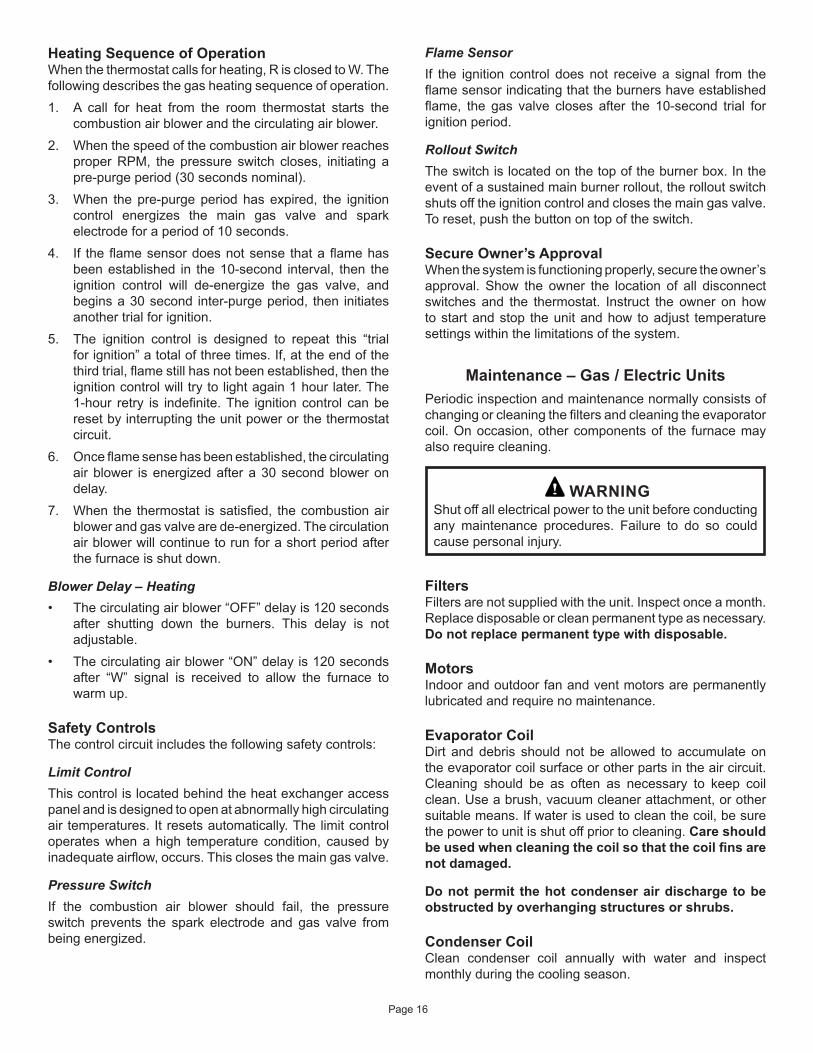
Control System Diagnostics
Table 4. Fault Codes
LED Status Flashing Rate Fault Description
Slow Flash One flash per second
Normal operation: No call for heat
Fast Flash Two flashes per second
Normal operation: Call for heat
2 FlashTwo flashes in second with
1-second pause
System lockout: Failed to detect or
sustain flame
3 FlashThree flashes in 1.5 seconds with 1-second pause
Pressure switch senses incorrect pressure or gas
valve coil is open.
4 FlashFour flashes in 2 seconds with 1-second pause
High limit or rollout switch open
5 FlashFive flashes in
2.5 seconds with 1-second pause
Flame sensed and gas valve not energized
Steady --Internal failure:
Micro-controller failure; self-check
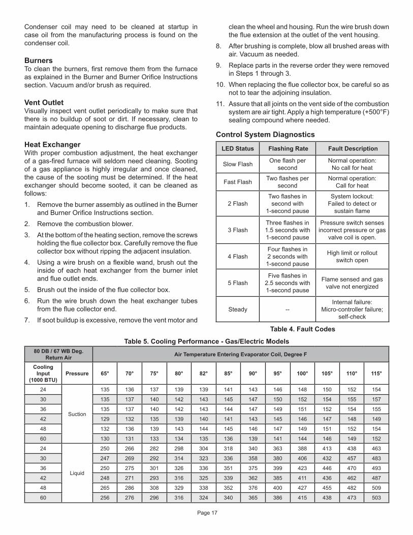
Table 5. Cooling Performance - Gas/Electric Models80 DB / 67 WB Deg.
Return Air Air Temperature Entering Evaporator Coil, Degree F
Cooling Input
(1000 BTU)Pressure 65° 70° 75° 80° 82° 85° 90° 95° 100° 105° 110° 115°
24
Suction
135 136 137 139 139 141 143 146 148 150 152 154
30 135 137 140 142 143 145 147 150 152 154 155 157
36 135 137 140 142 143 144 147 149 151 152 154 155
42 129 132 135 139 140 141 143 145 146 147 148 149
48 132 136 139 143 144 145 146 147 149 151 152 154
60 130 131 133 134 135 136 139 141 144 146 149 152
24
Liquid
250 266 282 298 304 318 340 363 388 413 438 463
30 247 269 292 314 323 336 358 380 406 432 457 483
36 250 275 301 326 336 351 375 399 423 446 470 493
42 248 271 293 316 325 339 362 385 411 436 462 487
48 265 286 308 329 338 352 376 400 427 455 482 509
60 256 276 296 316 324 340 365 386 415 438 473 503
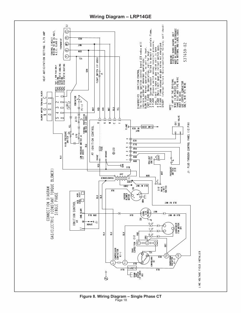
Page 18Figure 8. Wiring Diagram – Single Phase CT
Wiring Diagram – LRP14GE
Page 19
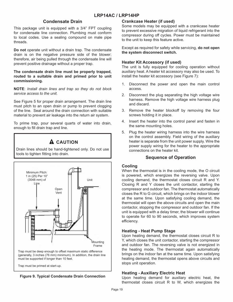
LRP14AC / LRP14HPCondensate Drain
This package unit is equipped with a 3/4” FPT coupling for condensate line connection. Plumbing must conform to local codes. Use a sealing compound on male pipe threads.
Do not operate unit without a drain trap. The condensate drain is on the negative pressure side of the blower; therefore, air being pulled through the condensate line will prevent positive drainage without a proper trap.
The condensate drain line must be properly trapped, routed to a suitable drain and primed prior to unit commissioning.
NOTE: Install drain lines and trap so they do not block service access to the unit.
See Figure 5 for proper drain arrangement. The drain line must pitch to an open drain or pump to prevent clogging of the line. Seal around the drain connection with suitable material to prevent air leakage into the return air system.
To prime trap, pour several quarts of water into drain, enough to fill drain trap and line.
Drain lines should be hand-tightened only. Do not use tools to tighten fitting into drain.
CAUTION
Minimum Pitch: 1 in (25) Per 10”
(3048 mm) of Line
Open Vent
Unit
Trap must be deep enough to offset maximum static difference (generally, 3 inches (76 mm) minimum). In addition, the drain line must be supported if longer than 10 feet.
Trap must be primed at start-up.
Mounting Frame
Figure 9. Typical Condensate Drain Connection
Crankcase Heater (if used)Some models may be equipped with a crankcase heater to prevent excessive migration of liquid refrigerant into the compressor during off cycles. Power must be maintained to the unit to keep this feature active.
Except as required for safety while servicing, do not open the system disconnect switch.
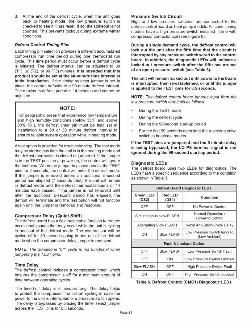
Heater Kit Accessory (if used)The unit is fully equipped for cooling operation without auxiliary heat. A heater kit accessory may also be used. To install the heater kit accessory (see Figure 7):
1. Disconnect the power and open the main control access.
2. Disconnect the plug separating the high voltage wire harness. Remove the high voltage wire harness plug and discard.
3. Remove the heater blockoff by removing the four screws holding it in place.
4. Insert the heater into the control panel and fasten in the same mounting holes.
5. Plug the heater wiring harness into the wire harness on the control assembly. Field wiring of the auxiliary heater is separate from the unit power supply. Wire the power supply wiring for the heater to the appropriate connections on the heater kit.
Sequence of Operation
CoolingWhen the thermostat is in the cooling mode, the O circuit is powered, which energizes the reversing valve. Upon cooling demand, the thermostat closes circuit R and Y. Closing R and Y closes the unit contactor, starting the compressor and outdoor fan. The thermostat automatically closes the R to G circuit, which brings on the indoor blower at the same time. Upon satisfying cooling demand, the thermostat will open the above circuits and open the main contactor, stopping the compressor and outdoor fan. If the unit is equipped with a delay timer, the blower will continue to operate for 60 to 90 seconds, which improves system efficiency.
Heating - Heat Pump StageUpon heating demand, the thermostat closes circuit R to Y, which closes the unit contactor, starting the compressor and outdoor fan. The reversing valve is not energized in the heating mode. The thermostat again automatically brings on the indoor fan at the same time. Upon satisfying heating demand, the thermostat opens above circuits and stops unit operation.
Heating - Auxiliary Electric HeatUpon heating demand for auxiliary electric heat, the thermostat closes circuit R to W, which energizes the
Page 20
heater sequencers as well as the indoor blower. Upon satisfying auxiliary heat demand, the thermostat opens above circuits and heating elements sequence off; blower continues to operate until all heating elements have turned off.
Defrost SystemThe defrost system includes two components: the defrost thermostat and the defrost control.
Defrost ThermostatThe defrost thermostat is located on the evaporator coil. When the defrost thermostat senses 35°F or cooler, the thermostat contacts close and send a signal to the defrost control board to start the defrost timing. It also terminates defrost when the liquid line warms up to 60°F.
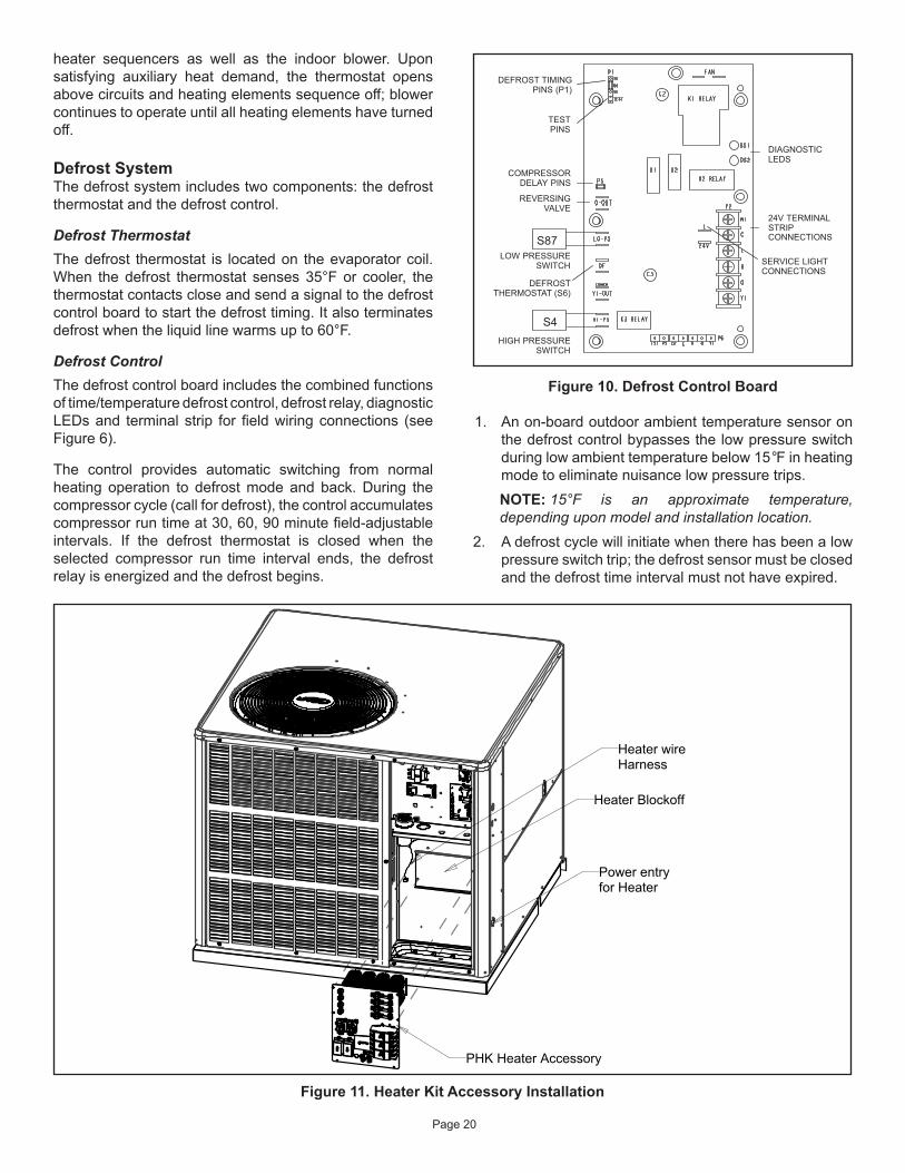
Defrost ControlThe defrost control board includes the combined functions of time/temperature defrost control, defrost relay, diagnostic LEDs and terminal strip for field wiring connections (see Figure 6).
The control provides automatic switching from normal heating operation to defrost mode and back. During the compressor cycle (call for defrost), the control accumulates compressor run time at 30, 60, 90 minute field-adjustable intervals. If the defrost thermostat is closed when the selected compressor run time interval ends, the defrost relay is energized and the defrost begins.
Figure 10. Defrost Control Board
24V TERMINALSTRIPCONNECTIONS
DIAGNOSTICLEDS
HIGH PRESSURESWITCH
TESTPINS
DEFROST TIMINGPINS (P1)
REVERSINGVALVE
DEFROSTTHERMOSTAT (S6)
LOW PRESSURESWITCH
COMPRESSORDELAY PINS
S4
S87
SERVICE LIGHTCONNECTIONS
1. An on-board outdoor ambient temperature sensor on the defrost control bypasses the low pressure switch during low ambient temperature below 15°F in heating mode to eliminate nuisance low pressure trips.NOTE: 15°F is an approximate temperature, depending upon model and installation location.
2. A defrost cycle will initiate when there has been a low pressure switch trip; the defrost sensor must be closed and the defrost time interval must not have expired.
Figure 11. Heater Kit Accessory Installation
Page 21
3. At the end of the defrost cycle, when the unit goes back to heating mode, the low pressure switch is checked to see if it has reset. If so, the strikeout is not counted. This prevents lockout during extreme winter conditions.
Defrost Control Timing PinsEach timing pin selection provides a different accumulated compressor run time period during one thermostat run cycle. This time period must occur before a defrost cycle is initiated. The defrost interval can be adjusted to 30 (T1), 60 (T2), or 90 (T3) minutes. It is intended that this product should be set at the 60-minute time interval at initial installation. If the timing selector jumper is not in place, the control defaults to a 90-minute defrost interval. The maximum defrost period is 14 minutes and cannot be adjusted.
For geographic areas that experience low temperature and high humidity conditions (below 35°F and above 80% RH), the defrost timer pin must be field set at installation to a 60 or 30 minute defrost interval to ensure reliable system operation while in heating mode.
NOTE:
A test option is provided for troubleshooting. The test mode may be started any time the unit is in the heating mode and the defrost thermostat is closed or jumpered. If the jumper is in the TEST position at power up, the control will ignore the test pins. When the jumper is placed across the TEST pins for 2 seconds, the control will enter the defrost mode. If the jumper is removed before an additional 5-second period has elapsed (7 seconds total), the unit will remain in defrost mode until the defrost thermostat opens or 14 minutes have passed. If the jumper is not removed until after the additional 5-second period has elapsed, the defrost will terminate and the test option will not function again until the jumper is removed and reapplied.
Compressor Delay (Quiet Shift)The defrost board has a field-selectable function to reduce occasional sounds that may occur while the unit is cycling in and out of the defrost mode. The compressor will be cycled off for 30 seconds going in and out of the defrost mode when the compressor delay jumper is removed.
NOTE: The 30-second “off” cycle is not functional when jumpering the TEST pins.
Time DelayThe defrost control includes a compressor timer, which ensures the compressor is off for a minimum amount of time between operating cycles.
The timed-off delay is 5 minutes long. The delay helps to protect the compressor from short cycling in case the power to the unit is interrupted or a pressure switch opens. The delay is bypassed by placing the timer select jumper across the TEST pins for 0.5 seconds.
Pressure Switch CircuitHigh and low pressure switches are connected to the defrost control board on heat pump models. Air conditioning models have a high pressure switch installed in line with compressor contactor coil (see Figure 6).
During a single demand cycle, the defrost control will lock out the unit after the fifth time that the circuit is interrupted by any pressure switch wired to the control board. In addition, the diagnostic LEDs will indicate a locked-out pressure switch after the fifth occurrence of an open pressure switch (see Table 3).
The unit will remain locked out until power to the board is interrupted, then re-established, or until the jumper is applied to the TEST pins for 0.5 seconds.
NOTE: The defrost control board ignores input from the low pressure switch terminals as follows:
• During the TEST mode• During the defrost cycle• During the 90-second start-up period• For the first 90 seconds each time the reversing valve
switches heat/cool modesIf the TEST pins are jumpered and the 5-minute delay is being bypassed, the LO PS terminal signal is not ignored during the 90-second start-up period.
Diagnostic LEDsThe defrost board uses two LEDs for diagnostics. The LEDs flash a specific sequence according to the condition as shown in Table 3.
Defrost Board Diagnostic LEDs
Green LED (DS2)
Red LED (DS1) Condition
OFF OFF No Power to Control
Simultaneous slow FLASH Normal Operation / Power to Control
Alternating Slow FLASH 5-min Anti-Short-Cycle Delay
ON Slow FLASH Low Pressure Switch Ignored (Low Ambient)
Fault & Lockout Codes
OFF Slow FLASH Low Pressure Switch Fault
OFF ON Low Pressure Switch Lockout
Slow FLASH OFF High Pressure Switch Fault
ON OFF High Pressure Switch Lockout
Table 6. Defrost Control (CMC1) Diagnostic LEDs
Page 22
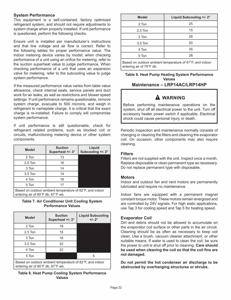
System PerformanceThis equipment is a self-contained, factory optimized refrigerant system, and should not require adjustments to system charge when properly installed. If unit performance is questioned, perform the following checks.
Ensure unit is installed per manufacturer’s instructions and that line voltage and air flow is correct. Refer to the following tables for proper performance value. The indoor metering device varies by model; when checking performance of a unit using an orifice for metering, refer to the suction superheat value to judge performance. When checking performance of a unit that uses an expansion valve for metering, refer to the subcooling value to judge system performance.
If the measured performance value varies from table value allowance, check internal seals, service panels and duct work for air leaks, as well as restrictions and blower speed settings. If unit performance remains questionable, remove system charge, evacuate to 500 microns, and weigh in refrigerant to nameplate charge. It is critical that the exact charge is re-installed. Failure to comply will compromise system performance.
If unit performance is still questionable, check for refrigerant related problems, such as blocked coil or circuits, malfunctioning metering device or other system components.
Model Suction Superheat +/- 3°
Liquid Subcooling +/- 2°
2 Ton 132.5 Ton 163 Ton 14
3.5 Ton 144 Ton 165 Ton 17
Based on outdoor ambient temperature of 82°F, and indoor entering air of 80°F db, 67°F wb.
Table 7. Air Conditioner Unit Cooling System Performance Values
Model Suction Superheat +/- 3°
Liquid Subcooling +/- 2°
2 Ton 18
2.5 Ton 16
3 Ton 16
3.5 Ton 22
4 Ton 22
5 Ton 5
Based on outdoor ambient temperature of 82°F, and indoor entering air of 80°F db, 67°F wb.
Table 8. Heat Pump Cooling System Performance Values
Model Liquid Subcooling +/- 2°
2 Ton 25
2.5 Ton 15
3 Ton 28
3.5 Ton 20
4 Ton 35
5 Ton 28
Based on outdoor ambient temperature of 47°F, and indoor entering air of 70°F db.
Table 9. Heat Pump Heating System Performance Values
Maintenance – LRP14AC/LRP14HP
Before performing maintenance operations on the system, shut off all electrical power to the unit. Turn off accessory heater power switch if applicable. Electrical shock could cause personal injury or death.
WARNING
Periodic inspection and maintenance normally consists of changing or cleaning the filters and cleaning the evaporator coil. On occasion, other components may also require cleaning.
FiltersFilters are not supplied with the unit. Inspect once a month. Replace disposable or clean permanent type as necessary. Do not replace permanent type with disposable.
MotorsIndoor and outdoor fan and vent motors are permanently lubricated and require no maintenance.
Indoor fans are equipped with a permanent magnet constant torque motor. These motors remain energized and are controlled by 24V signals. For high static applications, use Tap 3 for cooling speed and Tap 5 for heating speed.
Evaporator CoilDirt and debris should not be allowed to accumulate on the evaporator coil surface or other parts in the air circuit. Cleaning should be as often as necessary to keep coil clean. Use a brush, vacuum cleaner attachment, or other suitable means. If water is used to clean the coil, be sure the power to unit is shut off prior to cleaning. Care should be used when cleaning the coil so that the coil fins are not damaged.
Do not permit the hot condenser air discharge to be obstructed by overhanging structures or shrubs.
Page 23
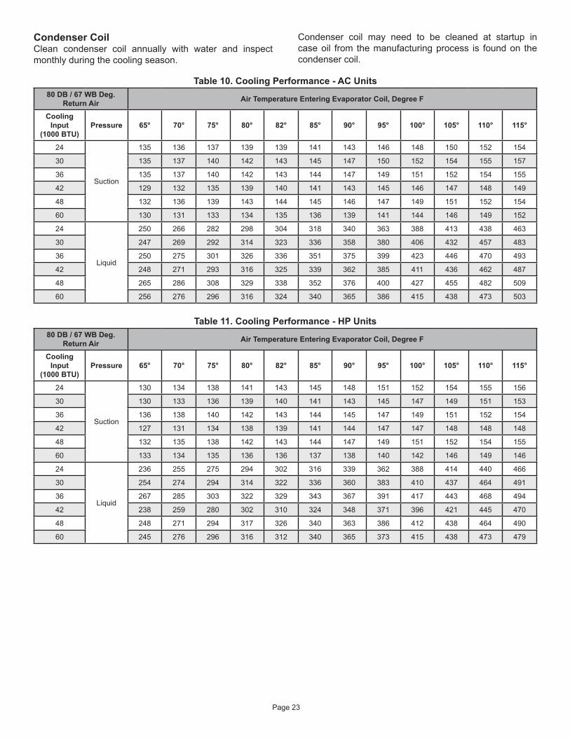
Condenser CoilClean condenser coil annually with water and inspect monthly during the cooling season.
Condenser coil may need to be cleaned at startup in case oil from the manufacturing process is found on the condenser coil.
Table 10. Cooling Performance - AC Units80 DB / 67 WB Deg.
Return Air Air Temperature Entering Evaporator Coil, Degree F
Cooling Input
(1000 BTU)Pressure 65° 70° 75° 80° 82° 85° 90° 95° 100° 105° 110° 115°
24
Suction
135 136 137 139 139 141 143 146 148 150 152 154
30 135 137 140 142 143 145 147 150 152 154 155 157
36 135 137 140 142 143 144 147 149 151 152 154 155
42 129 132 135 139 140 141 143 145 146 147 148 149
48 132 136 139 143 144 145 146 147 149 151 152 154
60 130 131 133 134 135 136 139 141 144 146 149 152
24
Liquid
250 266 282 298 304 318 340 363 388 413 438 463
30 247 269 292 314 323 336 358 380 406 432 457 483
36 250 275 301 326 336 351 375 399 423 446 470 493
42 248 271 293 316 325 339 362 385 411 436 462 487
48 265 286 308 329 338 352 376 400 427 455 482 509
60 256 276 296 316 324 340 365 386 415 438 473 503
Table 11. Cooling Performance - HP Units80 DB / 67 WB Deg.
Return Air Air Temperature Entering Evaporator Coil, Degree F
Cooling Input
(1000 BTU)Pressure 65° 70° 75° 80° 82° 85° 90° 95° 100° 105° 110° 115°
24
Suction
130 134 138 141 143 145 148 151 152 154 155 156
30 130 133 136 139 140 141 143 145 147 149 151 153
36 136 138 140 142 143 144 145 147 149 151 152 154
42 127 131 134 138 139 141 144 147 147 148 148 148
48 132 135 138 142 143 144 147 149 151 152 154 155
60 133 134 135 136 136 137 138 140 142 146 149 146
24
Liquid
236 255 275 294 302 316 339 362 388 414 440 466
30 254 274 294 314 322 336 360 383 410 437 464 491
36 267 285 303 322 329 343 367 391 417 443 468 494
42 238 259 280 302 310 324 348 371 396 421 445 470
48 248 271 294 317 326 340 363 386 412 438 464 490
60 245 276 296 316 312 340 365 373 415 438 473 479
Page 24
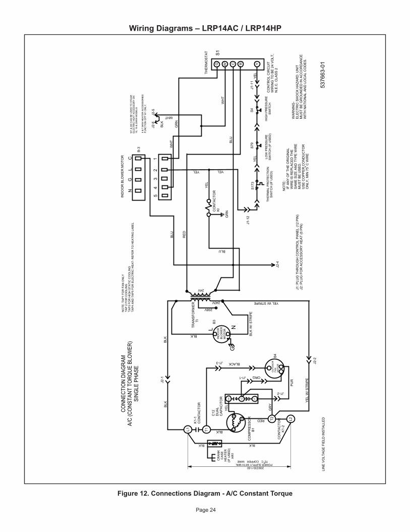
Wiring Diagrams – LRP14AC / LRP14HP
Figure 12. Connections Diagram - A/C Constant Torque
208/230-1-60POWER SUPPLY WITH MIN.
75CCOPPERWIRE
BLK
RE
D
YEL
RE
D
T2 L2
C HF
WHT
BLK
BR
N
PU
R
RE
D
RED
BLK
208V
240V
IND
OO
RB
LOW
ER
MO
TOR
RE
DU
CE
TO
6.0
0
RE
DU
CE
TO
10.0
0
RE
DU
CE
TO
BLU
YEL
CA
PA
CIT
OR
HM
LC
NO
NC
C
P-3
BLO
WE
RC
ON
TR
OL
NC
C
BLK
C
G
XFMR-R
R
XFMR-C
W1 C L R O Y1
FAN
O-O
UT
LO-P
S
DF
HI-P
S
CO
MM
ON
Y1
OU
T
22
24 V
YW
2
RE
D
YE
L
BLU
WH
T
GR
N
OR
N
RED BLU
BLU
YE
L
BLU
2
W1
& W
2 C
AN
BE
US
ED
TO
ST
AG
EE
LEC
TR
IC H
EA
T A
CC
ES
SO
RY
ON
15 &
20K
W M
OD
ELS
5, 7
.5 &
10K
W H
EA
TE
R A
CC
ES
SO
RIE
SF
UN
CT
ION
OF
F W
1 O
NLY
.
BLK
BLK
DE
FRO
ST
CO
NTR
OL
BLU
WHT
DE
FRO
ST
CO
NTR
OL
P-2
P-4
P-6
P-5
LOW
PR
ES
SU
RE
SW
ITC
H (I
F U
SE
D)
G W1
C R
YEL W/ STRIPE
CO
NTR
OL
CIR
CU
IT
WIR
ING
TO
BE
24
VO
LT,
N.E
.C. C
LAS
S 2
L1 T1
T2 L2
CH F
OU
TDO
OR
FAN
M
OTO
R
C12
DU
AL
CA
PA
CIT
OR
CO
MP
RE
SS
OR
CS
R
5376
63-0
1
GR
Y
RED
BLK
208V
240V
24V
IND
OO
RB
LOW
ER
MO
TOR
NO
TE:
IF
AN
Y O
F TH
E O
RIG
INA
L W
IRE
IS R
EP
LAC
ED
TH
E S
AM
E S
IZE
AN
D T
YP
E W
IRE
MU
ST
BE
US
ED
. U
SE
CO
PP
ER
CO
ND
UC
TOR
ON
LY, M
IN 7
5C
WIR
E
LIN
E V
OLT
AG
E F
IELD
INS
TALL
ED
WA
RN
ING
-E
LEC
TRIC
SH
OC
K H
AZA
RD
. UN
ITM
US
T B
E G
RO
UN
DE
D IN
AC
CO
RD
AN
CE
WIT
H N
ATI
ON
AL
AN
D L
OC
AL
CO
DE
S.
YE
L
Y
WH
T
GR
N
5 &
7.5
KW
HE
ATE
R A
CC
ES
SO
RIE
SFU
NC
TIO
N O
FF W
1 O
NLY
.
BLK
J2-1
J2-2
BLK
C 12
34
5J2
-6J2
-5
WHT
BLU
RE
D
YE
L
WH
T
B1
PU
R
B4
BLACK
ORG
L NG
B3
S1
TRA
NS
FOR
ME
R
TI
LG
N
BLK
K1-
1C
ON
TAC
TOR
YE
L W
/ STR
IPE
CO
NTA
CTO
RK
1-2
BLU
BLU
GR
NCO
NTA
CTO
RK
I
YE
L
BLK
J2-4
NO
TE: T
AP
1 FO
R F
AN
ON
LYTA
P 2
FO
R C
OO
LIN
GTA
P3
FOR
HIG
H S
TATI
C C
OO
LIN
GTA
P4
AN
D T
AP
5 FO
R E
LEC
TRIC
HE
AT-
RE
FER
TO
HE
ATI
NG
LA
BE
L
BLK
W/ S
TRIP
EY
EL
THE
RM
AL
PR
OTE
CTI
ON
SW
ITC
H (I
F U
SE
D)
208/
230V
-1-6
0
BLO
WE
R S
PE
ED
CH
AR
T
UN
ITFA
CTOR
Y SH
IPPE
D SE
TTIN
GS
CO
OLI
NG
INP
UT
(BLK
)
24
LOW
30
ME
D
36
HIG
H
42
LOW
48
ME
D
60
HIG
H
GW
1C
RO
CO
NTA
CTO
R
THE
RM
OS
TAT
HIG
H P
RE
SS
UR
ES
WIT
CH
(IF
US
ED
)
L1 T1
CO
ND
EN
SE
RFA
N M
OTO
R
CO
MP
RE
SS
OR
CO
NTA
CTO
R
CO
MP
RE
SS
OR
CO
NTA
CTO
R
DU
AL
CA
PA
CIT
OR
CO
MP
RE
SS
OR
TRANSFORMER
CS
R
L2
L1
5376
63-0
1
CONN
ECTI
ON
DIAG
RAM
, HEA
T PU
MP
- PAC
KAG
ED
24V
NO
TE:
IF
AN
Y O
F TH
E O
RIG
INA
L W
IRE
IS R
EP
LAC
ED
TH
E S
AM
E S
IZE
AN
D T
YP
E W
IRE
MU
ST
BE
US
ED
. U
SE
CO
PP
ER
CO
ND
UC
TOR
ON
LY, M
IN 7
5C
WIR
E C
ON
NE
CTI
ON
MU
ST
BE
JU
MP
ER
ED
WH
EN
PR
ES
SU
RE
SW
ITC
H IS
NO
T U
SE
D.LI
NE
VO
LTA
GE
FIE
LD IN
STA
LLE
D
WA
RN
ING
-E
LEC
TRIC
SH
OC
K H
AZA
RD
. UN
ITM
US
T B
E G
RO
UN
DE
D IN
AC
CO
RD
AN
CE
WIT
H N
ATI
ON
AL
AN
D L
OC
AL
CO
DE
S.
SE
E C
HA
RT
FOR
WIR
ING
L M
H C
MO
TOR
SP
EE
D T
AP
S
FUS
E
BLO
WE
R
CO
NTR
OL
DIA
GN
OST
IC C
OD
ES F
OR
DEF
RO
ST C
ON
TRO
L LE
DS
Note
: Bec
ause
the
Pres
sure
Swi
tche
s ar
e m
onito
red
only
when
"Y1"
(Inp
ut) i
s ac
tive,
the
code
for p
ress
ure
switc
h op
en w
ill no
t be
seen
whe
n "Y
1" is
off.
Inst
ead,
the
"Nor
mal
Ope
ratio
n" o
r"A
nti S
hort
Cycle
" cod
e wi
ll be
seen
. Al
so, w
hen
a pr
essu
re s
witc
h op
ens
and
caus
ed a
sho
rt cy
cle lo
ckou
t, th
e pr
essu
re s
witc
h-op
enco
de w
ill be
see
n un
til it
close
s, th
en th
e sh
ort c
ycle
lock
out c
ode
will f
lash
unl
ess
it ha
s al
read
yex
pire
d.
RE
V. V
ALV
E
DE
FRO
ST
T'S
TAT
P-1
(See
inst
ruct
ions
or m
arkin
gs o
n Sy
stem
Dia
gnos
ticM
odul
e fo
r cod
es o
f Sys
tem
Dia
gnos
tic M
odul
e)
YELYEL
HIG
H P
RE
SS
UR
ES
WIT
CH
LOW
PR
ES
SU
RE
SW
ITC
H (I
F U
SE
D)
J1: P
LUG
TH
RO
UG
H C
ON
TRO
L P
AN
EL
(12
PIN
)J2
: PLU
G F
OR
AC
CE
SS
OR
Y H
EA
T (6
PIN
)
IND
OO
R B
LOW
ER
MO
TOR
B-3
J1-3
J1-1
J1-2
J1-1
2S4
S79
S173
J1-1
1
CONN
ECTI
ON
DIAG
RAM
A/C
(CO
NSTA
NT T
ORQ
UE B
LOW
ER)
SING
LE P
HASE
THE
RM
OS
TAT
W1
& W
2 C
AN
BE
US
ED
TO
STA
GE
ELE
CTR
IC H
EA
T A
CC
ES
SO
RY
ON
10, 1
5 &
20K
W M
OD
ELS
CR
AN
KC
AS
EH
EA
TER
(IF U
SE
D)
BLK BLK
HR
1
Desc
riptio
nD
S2
(GR
EE
N)
DS
1 (R
ED
)
No P
ower
to C
ontro
lO
FFO
FF
Norm
al O
pera
tion
/ Pow
er to
Cont
rol
Sim
ulta
neou
s Sl
ow F
lash
Anti-
Shor
t Cyc
le L
ocko
utAl
tern
ate
Slow
Fla
sh
Low
Pres
sure
Swi
tch
Faul
tO
FFSl
ow F
lash
Low
Pres
sure
Swi
tch
Lock
out
OFF
ON
High
Pre
ssur
e Sw
itch
Faul
tSl
ow F
lash
OFF
High
Pre
ssur
e Sw
itch
Lock
out
ON
OFF
Page 25
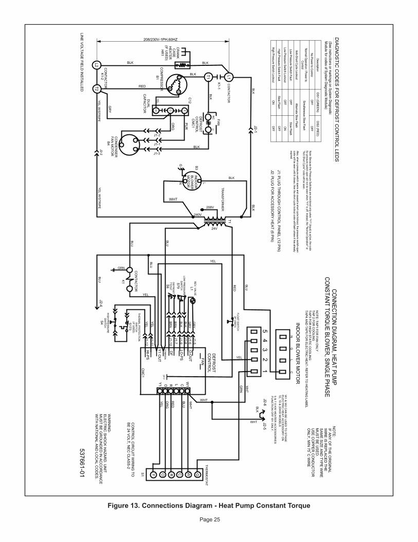
208/230V-1PH,60HZ
DescriptionD
S1 (G
RE
EN
)D
S2 (R
ED
)
No Power to ControlO
FFO
FF
Normal O
peration / Power toControl
Simultaneous Slow Flash
Anti-Short Cycle LockoutAlternate Slow Flash
Low Pressure Switch FaultO
FFSlow Flash
Low Pressure Switch LockoutO
FFO
N
High Pressure Switch FaultSlow Flash
OFF
High Pressure Switch LockoutO
NO
FF
GW1
CRO
THE
RM
OS
TAT
L1T1
T2L2
CH F
DU
AL
CA
PA
CITO
R
CO
MP
RE
SS
OR
CS
R
537661-01
CONNECTIO
N DIAGRAM
, HEAT PUMP
CONSTANT TO
RQUE BLO
WER, SING
LE PHASERED
BLK
208V
240V
24V
IND
OO
RB
LOW
ER
MO
TOR
NO
TE:
IF AN
Y O
F THE
OR
IGIN
AL
WIR
E IS
RE
PLA
CE
D TH
E S
AM
E S
IZE A
ND
TYP
E W
IRE
MU
ST B
E U
SE
D.
US
E C
OP
PE
R C
ON
DU
CTO
R O
NLY
, MIN
75C
WIR
E
LINE
VO
LTAG
E FIE
LD IN
STA
LLED
WA
RN
ING
-E
LEC
TRIC
SH
OC
K H
AZA
RD
. UN
ITM
US
T BE
GR
OU
ND
ED
IN A
CC
OR
DA
NC
EW
ITH N
ATIO
NA
L AN
D LO
CA
L CO
DE
S.
BLU
YE
L
NC
C
W1CLROY1
FAN
O-O
UT
LO-P
S
DF
HI-P
S
CO
MM
ON
Y1 O
UT
24 V
Y
RE
D
YE
L
BLU
WH
T
GR
N
OR
G
DIAG
NO
STIC C
OD
ES FOR
DEFR
OST C
ON
TRO
L LEDS
Note: Because the Pressure Switches are monitored only when "Y1" (Input) is active, the code
for pressure switch open will not be seen when "Y1" is off. Instead, the "Normal O
peration" or"Anti Short Cycle" code will be seen. Also, when a pressure switch opens and caused a short cycle lockout, the pressure switch-opencode will be seen until it closes, then the short cycle lockout code will flash unless it has alreadyexpired.
W1 &
W2 C
AN
BE
US
ED
TO
ST
AG
EE
LEC
TR
IC H
EA
T A
CC
ES
SO
RY
ON
10, 15 & 20K
W M
OD
ELS
5 & 7.5 K
W H
EA
TE
R A
CC
ES
SO
RIE
SF
UN
CT
ION
OF
F W
1 ON
LY.
BLK
DE
FRO
ST
CO
NTR
OL
WHT
DE
FRO
ST
CO
NTR
OL
J2-2J2-4
BLK
C12
34
5
WHT
BLU
RE
D
BLU
WH
T
LNG
NO
TE: TA
P1 FO
R FA
N O
NLY
TAP
2 FOR
CO
OLIN
GTA
P3 FO
R H
IGH
STA
TIC C
OO
LING
TAP
4 AN
D TA
P5 FO
R E
LEC
TRIC
HE
AT- R
EFE
R TO
HE
ATIN
G LA
BE
L
TRA
NS
FOR
ME
R
LG
N
BLK
CO
NTA
CTO
R
BLK
YE
L W/S
TRIP
E
CO
NTA
CTO
R
(See instructions or markings on System
DiagnosticM
odule for codes of System Diagnostic M
odule)
BLK
BLU
WHTFA
N
YEL
YE
L W/S
TRIP
EK
1-2
K1-1
J2-1
B1
CM
C1
C12
GR
Y
OR
G
BLK
CO
ND
EN
SE
RFA
N M
OTO
R
PU
R
J1-2
J1-1
J1-3
B4
B3
CO
NTA
CTO
R
K1
HIG
H P
RE
SS
UR
ES
WITC
H
THE
RM
AL P
RO
TEC
TION
SW
ITCH
(IF US
ED
)S
173
S4
J1-11
J1-12
RE
V. V
ALV
E
DE
FRO
ST
T'STA
T
LOW
PR
ES
SU
RE
SW
ITCH
GR
YG
RY
BLK
BLK
BR
NB
RN
L1
S79
S6
J1-5J1-6J1-8J1-9J1-7J1-10
YEL
T1
BLU
YEL
J2-6J2-5
S1
CO
NTR
OL C
IRC
UIT W
IRIN
G TO
BE
24 VO
LT, NE
C C
LAS
S-2
CM
C1
J1: PLU
G TH
RO
UG
H C
ON
TRO
L PA
NE
L (12 PIN
)
J2: PLU
G FO
R A
CC
ES
SO
RY
HE
AT (6 P
IN)
IND
OO
R B
LOW
ER
MO
TOR
GRN
FLOA
T SW
ITCH
(IF US
ED
)
YE
L
YE
L
CR
AN
KC
AS
EH
EA
TER
(IF US
ED
)
BLKBLK
HR
1
Figure 13. Connections Diagram - Heat Pump Constant Torque
Related Documents

![INSTALLATION INSTRUCTIONS - Lennox 240009135, Rev. C [06/2012] RETAIN THESE INSTRUCTIONS FOR FUTURE REFERENCE These instructions must be affi xed on or adjacent to the boiler. GAS](https://static.cupdf.com/doc/110x72/5ab1f3537f8b9ac3348d074a/installation-instructions-lennox-240009135-rev-c-062012-retain-these-instructions.jpg)


