ATTENTION INSTALLING PERSONNEL: Prior to installation, thoroughly familiarize yourself with this Installation Manual. Observe all safety warnings. Dur- ing installation or repair, caution is to be observed. It is your responsibility to install the product safely and to educate the customer on its safe use. RECOGNIZE THIS SYMBOL AS A SAFETY PRECAUTION. These installation instructions cover the outdoor installation of single package heating and cooling units. See the Specification Sheet applicable to your model for information regarding acces- sories. *NOTE: Please contact your distributor or our website for the applicable Specification Sheet referred to in this manual. This Forced Air Central Unit Design Complies With Requirements Embodied In The American National Standard / National Stan- dard of Canada Shown Below. ANSI Z21.47•CSA-2.3 Central Furnaces INSTALLATION INSTRUCTIONS DCG SERIES LIGHT COMMERCIAL PACKAGED GAS UNIT 3 to 6 TON © 2013 - 2015 5151 San Felipe St., Suite 500, Houston, TX 77056 w w w .dai kinc om f ort.c om Our continuing commitment to quality products may mean a change in specifications without notice. IOD-1004B 2/2015 Index Replacement Parts ................................................................ 2 Safety Instructions ................................................................ 2 General Information ............................................................. 3 Unit Location ........................................................................ 4 Clearances ............................................................................ 5 Roof Curb Post-Installation Checks ....................................... 6 Roof Top Duct Connections ................................................... 6 Rigging Details ...................................................................... 6 Electrical Wiring .................................................................... 7 Gas Supply Piping ................................................................. 9 Propane Gas Installations ................................................... 10 Circulating Air and Filters .................................................... 11 Venting ............................................................................... 12 Condensate Drain Connection ............................................ 12 Startup, Adjustments, and Checks ...................................... 12 Air flow Adjustments .......................................................... 13 Motor Sheave Adjustments ................................................ 14 Gas System Check ............................................................... 15 Normal Sequence Of Operation .......................................... 17 Maintenance ...................................................................... 20 Troubleshooting .................................................................. 21 Appendix A Blower Performance Tables ............................. 23 Direct Drive .................................................................... 23 DCG036 Down Shot and Horizontal ............................ 23 DCG048 Down Shot and Horizontal ............................ 24 DCG060 Down Shot .................................................... 25 DCG060 Horizontal ..................................................... 26 Belt Drive ....................................................................... 27 Standard Down Shot .................................................. 27 High Static Down Shot ................................................ 28 Standard Horizontal ................................................... 29 High Static Horizontal ................................................. 30 Appendix B Electrical Data .................................................. 31 Appendix C Unit Dimensions ............................................... 32 Appendix D Wiring Diagrams .............................................. 33 Start-Up Checklist ............................................................... 55

Welcome message from author
This document is posted to help you gain knowledge. Please leave a comment to let me know what you think about it! Share it to your friends and learn new things together.
Transcript
ATTENTION INSTALLING PERSONNEL:
Prior to installation, thoroughly familiarize yourself withthis Installation Manual. Observe all safety warnings. Dur-ing installation or repair, caution is to be observed.
It is your responsibility to install the product safely and toeducate the customer on its safe use.
RECOGNIZE THIS SYMBOL AS A SAFETY PRECAUTION.
These installation instructions cover the outdoor installation ofsingle package heating and cooling units. See the SpecificationSheet applicable to your model for information regarding acces-sories.
*NOTE: Please contact your distributor or our website for theapplicable Specification Sheet referred to in this manual.
This Forced Air Central Unit Design Complies With RequirementsEmbodied In The American National Standard / National Stan-dard of Canada Shown Below.
ANSI Z21.47•CSA-2.3 Central Furnaces
INSTALLATION INSTRUCTIONS
DCG SERIESLIGHT COMMERCIAL PACKAGED GAS UNIT3 to 6 TON
© 2013 - 20155151 San Felipe St., Suite 500, Houston, TX 77056
www.daikincomfort.com
Our continuing commitment to quality products may mean a change in specifications without notice.IOD-1004B2/2015
IndexReplacement Parts ................................................................ 2Safety Instructions ................................................................ 2General Information ............................................................. 3Unit Location ........................................................................ 4Clearances ............................................................................ 5Roof Curb Post-Installation Checks ....................................... 6Roof Top Duct Connections ................................................... 6Rigging Details ...................................................................... 6Electrical Wiring .................................................................... 7Gas Supply Piping ................................................................. 9Propane Gas Installations ................................................... 10Circulating Air and Filters .................................................... 11Venting ............................................................................... 12Condensate Drain Connection ............................................ 12Startup, Adjustments, and Checks ...................................... 12Air flow Adjustments .......................................................... 13Motor Sheave Adjustments ................................................ 14Gas System Check ............................................................... 15Normal Sequence Of Operation .......................................... 17Maintenance ...................................................................... 20Troubleshooting.................................................................. 21Appendix A Blower Performance Tables ............................. 23
Direct Drive .................................................................... 23DCG036 Down Shot and Horizontal ............................ 23DCG048 Down Shot and Horizontal ............................ 24DCG060 Down Shot .................................................... 25DCG060 Horizontal ..................................................... 26
Belt Drive ....................................................................... 27Standard Down Shot .................................................. 27High Static Down Shot ................................................ 28Standard Horizontal ................................................... 29High Static Horizontal ................................................. 30
Appendix B Electrical Data .................................................. 31Appendix C Unit Dimensions ............................................... 32Appendix D Wiring Diagrams .............................................. 33Start-Up Checklist ............................................................... 55

2
DO NOT CONNECT TO OR USE ANY DEVICE THAT IS NOT DESIGN CERTIFIED BY DAIKIN FOR USE WITH THIS UNIT. SERIOUS PROPERTY DAMAGE, PERSONAL INJURY, REDUCED UNIT PERFORMANCE AND/OR HAZARDOUS CONDITIONS MAY RESULT FROM THE USE OF SUCH NON-APPROVED DEVICES.
WARNING
WARNING
THIS PRODUCT CONTAINS OR PRODUCES A CHEMICAL OR CHEMICALS WHICHMAY CAUSE SERIOUS ILLNESS OR DEATH AND WHICH ARE KNOWN TO THESTATE OF CALIFORNIA TO CAUSE CANCER, BIRTH DEFECTS OR OTHERREPRODUCTIVE HARM.
WARNING
TO AVOID PROPERTY DAMAGE, PERSONAL INJURY OR DEATH, DO NOT USETHIS UNIT IF ANY PART HAS BEEN UNDER WATER. IMMEDIATELY CALL AQUALIFIED SERVICE TECHNICIAN TO INSPECT THE FURNACE AND TO REPLACEANY PART OF THE CONTROL SYSTEM AND ANY GAS CONTROL HAVING BEENUNDER WATER.
THIS UNIT MUST NOT BE USED AS A "CONSTRUCTION HEATER" DURING THE FINISHING PHASES OF CONSTRUCTION ON A NEW STRUCTURE. THIS TYPE OF USE MAY RESULT IN PREMATURE FAILURE OF THE UNIT DUE TO EXTREMELY LOW RETURN AIR TEMPERATURE AND EXPOSURE TO CORROSIVE OR VERYDIRTY ATMOSPHERES.
HIGH VOLTAGE! DISCONNECT ALL POWER BEFORE SERVICING OR INSTALLING THIS UNIT. MULTIPLE POWER SOURCES MAY BE PRESENT. FAILURE TO DO SO MAY CAUSE PROPERTY DAMAGE, PERSONAL INJURY OR DEATH.
WARNING
WARNINGTO PREVENT THE RISK OF PROPERTY DAMAGE, PERSONAL INJURY, OR DEATH,DO NOT STORE COMBUSTIBLE MATERIALS OR USE GASOLINE OR OTHERFLAMMABLE LIQUIDS OR VAPORS IN THE VICINITY OF THIS APPLIANCE.
WARNING
HIGH VOLTAGE! INSTALLATION AND REPAIR OF THIS UNIT SHOULD BE PERFORMED ONLY BY INDIVIDUALS MEETING(AT A MINIMUM) THE REQUIREMENTS OF AN “ENTRY LEVEL TECHNICIAN” AS SPECIFIED BY THE AIR CONDITIONING, HEATING AND REFRIGERATION INSTITUTE (AHRI). ATTEMPTING TO INSTALL OR REPAIR THIS UNIT WITHOUT SUCH BACKGROUND MAY RESULT IN PRODUCT DAMAGE, PERSONAL INJURY OR DEATH.
REPLACEMENT PARTS
ORDERING PARTS
When reporting shortages or damages, or ordering repairparts, give the complete unit model and serial numbers asstamped on the unit’s nameplate.
Replacement parts for this appliance are available throughyour contractor or local distributor. For the location of yournearest distributor, consult the white business pages, theyellow page section of the local telephone book or contact:
CONSUMER AFFAIRSDAIKIN NORTH AMERICA LLC
7401 SECURITY WAYHOUSTON, TEXAS 77040
855-770-5678
SAFETY INSTRUCTIONS
TO THE INSTALLER
Before installing this unit, please read this manual tofamiliarize yourself on the specific items which must beadhered to, including maximum external static pressure tounit, air temperature rise, minimum or maximum CFM andmotor speed connections.
Keep this literature in a safe place for future reference.
IF THE INFORMATION IN THESE INSTRUCTIONS IS NOT FOLLOWED EXACTLY, A FIRE OR EXPLOSION MAY RESULT CAUSING PROPERTY DAMAGE, PERSONAL INJURY OR LOSS OF LIFE.- DO NOT STORE OR USE GASOLINE OR OTHER FLAMMABLE VAPORS AND LIQUIDS IN THE VICINITY OF THIS OR ANY OTHER APPLIANCE.- WHAT TO DO IF YOU SMELL GAS:
* DO NOT TRY TO LIGHT ANY APPLIANCE.* DO NOT TOUCH ANY ELECTRICAL SWITCH; DO NOT USE
ANY PHONE IN YOUR BUILDING.* IMMEDIATELY CALL YOUR GAS SUPPLIER FROM A
NEIGHBORS PHONE. FOLLOW THE GAS SUPPLIERS INSTRUCTIONS.
* IF YOU CANNOT REACH YOUR GAS SUPPLIER, CALL THE FIRE DEPARTMENT.- INSTALLATION AND SERVICE MUST BE PERFORMED BY A QUALIFIED INSTALLER, SERVICE AGENCY OR THE GAS SUPPLIER
WARNING
WARNING
SHOULD OVERHEATING OCCUR OR THE GAS SUPPLY FAIL TO SHUT OFF, TURN
OFF THE MANUAL GAS SHUTOFF VALVE EXTERNAL TO THE FURNACE BEFORE
TURNING OFF THE ELECTRICAL SUPPLY.
SHEET METAL PARTS, SCREWS, CLIPS AND SIMILAR ITEMS INHERENTLY HAVE SHARP EDGES, AND IT IS NECESSARY THAT THE INSTALLER AND SERVICE PERSONNEL EXERCISE CAUTION.
CAUTION
3
GENERAL INFORMATION
WARNING
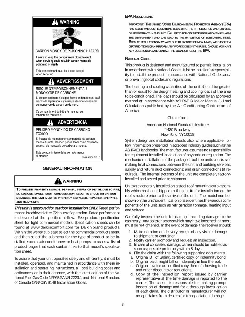
TO PREVENT PROPERTY DAMAGE, PERSONAL INJURY OR DEATH, DUE TO FIRE,EXPLOSIONS, SMOKE, SOOT, CONDENSATION, ELECTRIC SHOCK OR CARBONMONOXIDE, THIS UNIT MUST BE PROPERLY INSTALLED, REPAIRED, OPERATED,AND MAINTAINED.
This unit is approved for outdoor installation ONLY. Rated perfor-mance is achieved after 72 hours of operation. Rated performanceis delivered at the specified airflow. See product specificationsheet for light commercial models. Specification sheets can befound at www.daikincomfort.com for Daikin brand products.Within the website, please select the commercial products menuand then select the submenu for the type of product to be in-stalled, such as air conditioners or heat pumps, to access a list ofproduct pages that each contain links to that model’s specifica-tion sheet.
To assure that your unit operates safely and efficiently, it must beinstalled, operated, and maintained in accordance with these in-stallation and operating instructions, all local building codes andordinances, or in their absence, with the latest edition of the Na-tional Fuel Gas Code NFPA54/ANSI Z223.1 and National Standardof Canada CAN/CSA B149 Installation Codes.
EPA REGULATIONS
IMPORTANT: THE UNITED STATES ENVIRONMENTAL PROTECTION AGENCY (EPA)HAS ISSUED VARIOUS REGULATIONS REGARDING THE INTRODUCTION AND DISPOSALOF REFRIGERANTS IN THIS UNIT. FAILURE TO FOLLOW THESE REGULATIONS MAY HARMTHE ENVIRONMENT AND CAN LEAD TO THE IMPOSITION OF SUBSTANTIAL FINES.BECAUSE REGULATIONS MAY VARY DUE TO PASSAGE OF NEW LAWS, WE SUGGEST ACERTIFIED TECHNICIAN PERFORM ANY WORK DONE ON THIS UNIT. SHOULD YOU HAVEANY QUESTIONS PLEASE CONTACT THE LOCAL OFFICE OF THE EPA.
NATIONAL CODES
This product is designed and manufactured to permit installationin accordance with National Codes. It is the installer’s responsibil-ity to install the product in accordance with National Codes and/or prevailing local codes and regulations.
The heating and cooling capacities of the unit should be greaterthan or equal to the design heating and cooling loads of the areato be conditioned. The loads should be calculated by an approvedmethod or in accordance with ASHRAE Guide or Manual J - LoadCalculations published by the Air Conditioning Contractors ofAmerica.
Obtain from:
American National Standards Institute1430 Broadway
New York, NY 10018System design and installation should also, where applicable, fol-low information presented in accepted industry guides such as theASHRAE Handbooks. The manufacturer assumes no responsibilityfor equipment installed in violation of any code or regulation. Themechanical installation of the packaged roof top units consists ofmaking final connections between the unit and building services;supply and return duct connections; and drain connections (if re-quired). The internal systems of the unit are completely factory-installed and tested prior to shipment.
Units are generally installed on a steel roof mounting curb assem-bly which has been shipped to the job site for installation on theroof structure prior to the arrival of the unit. The model numbershown on the unit’s identification plate identifies the various com-ponents of the unit such as refrigeration tonnage, heating inputand voltage.
Carefully inspect the unit for damage including damage to thecabinetry. Any bolts or screws which may have loosened in transitmust be re-tightened. In the event of damage, the receiver should:
1. Make notation on delivery receipt of any visible damageto shipment or container.
2. Notify carrier promptly and request an inspection.3. In case of concealed damage, carrier should be notified as
soon as possible-preferably within 5 days.4. File the claim with the following supporting documents:a. Original Bill of Lading, certified copy, or indemnity bond.b. Original paid freight bill or indemnity in lieu thereof.c. Original invoice or certified copy thereof, showing trade
and other discounts or reductions.d. Copy of the inspection report issued by carrier
representative at the time damage is reported to thecarrier. The carrier is responsible for making promptinspection of damage and for a thorough investigationof each claim. The distributor or manufacturer will notaccept claims from dealers for transportation damage.

4
NOTE: When inspecting the unit for transportation damage, re-move all packaging materials. Recycle or dispose of the packagingmaterial according to local codes.
PRE-INSTALLATION CHECKS
Carefully read all instructions for the installation prior to installingunit. Ensure each step or procedure is understood and any specialconsiderations are taken into account before starting installation.Assemble all tools, hardware and supplies needed to complete theinstallation. Some items may need to be purchased locally.
UNIT LOCATION
WARNING
TO PREVENT POSSIBLE EQUIPMENT DAMAGE, PROPERTY DAMAGE, PERSONALINJURY OR DEATH, THE FOLLOWING BULLET POINTS MUST BE OBSERVEDWHEN INSTALLING THE UNIT.
IMPORTANT NOTE: Remove wood shipping rails prior to installa-tion of the unit.
ALL INSTALLATIONS:
IMPORTANT NOTE: Unit should be energized 24 hours prior tocompressor start up to ensure crankcase heater has suffi-ciently warmed the compressors. Compressor damage mayoccur if this step is not followed.
NOTE: Appliance is shipped from factory for vertical ductapplication.Proper installation of the unit ensures trouble-free operation. Im-proper installation can result in problems ranging from noisyoperation to property or equipment damages, dangerous condi-tions that could result in injury or personal property damage andthat are not covered by the warranty. Give this booklet to the userand explain it’s provisions. The user should retain these instruc-tions for future reference.
• For proper flame pattern within the heat exchanger andproper condensate drainage, the unit must be mountedlevel.
• The flue outlet must be at least 12 inches from any openingthrough which flue gases could enter a building, and atleast three feet above any forced air inlet located withinten feet. The economizer/manual fresh air intake/motorized fresh air intake and combustion air inletmounted on the unit are not affected by this restriction.
• To avoid possible corrosion of the heat exchanger, do notlocate the unit in an area where the outdoor air (i.e.combustion air for the unit) will be frequentlycontaminated by compounds containing chlorine orfluorine. Common sources of such compounds includeswimming pool chemicals and chlorine bleaches, paintstripper, adhesives, paints, varnishes, sealers, waxes (whichare not yet dried) and solvents used during constructionand remodeling. Various commercial and industrialprocesses may also be sources of chlorine/fluorinecompounds.
• To avoid possible illness or death of the building occupants,do NOT locate outside air intake device (economizer,manual fresh air intake, motorized fresh air intake) tooclose to an exhaust outlet, gas vent termination, orplumbing vent outlet. For specific distances required,consult local codes.
• Allow minimum clearances from the enclosure for fireprotection, proper operation, and service access (see unitclearances). These clearances must be permanentlymaintained.
• The combustion air inlet and flue outlet on the unit mustnever be obstructed. If used, do not allow the economizer/manual fresh air damper/ motorized fresh air damper tobecome blocked by snow or debris. In some climates orlocations, it may be necessary to elevate the unit to avoidthese problems.
• When the unit is heating, the temperature of the returnair entering the unit must be a minimum of 55° F.
GROUND LEVEL INSTALLATIONS ONLY:
• When the unit is installed on the ground adjacent to thebuilding, a level concrete (or equal) base is recommended.Prepare a base that is 3” larger than the package unitfootprint and a minimum of 3” thick.
• The base should also be located where no runoff of waterfrom higher ground can collect in the unit.
ROOF TOP INSTALLATIONS ONLY:
• To avoid possible property damage or personal injury, theroof must have sufficient structural strength to carry theweight of the unit(s) and snow or water loads as requiredby local codes. Consult a structural engineer to determinethe weight capabilities of the roof.
• The unit may be installed directly on wood floors or onClass A, Class B, or Class C roof covering material.
• To avoid possible personal injury, a safe, flat surface forservice personnel should be provided.
• As indicated on the unit data plate, a minimum clearanceof 36” to any combustible material is required on thefurnace access side of the unit. All combustible materialsmust be kept out of this area.
• This 36” clearance must also be maintained to insureproper combustion air and flue gas flow. The combustionair intake and furnace flue discharge must not be blockedfor any reason, including blockage by snow.
• Adequate clearances from the furnace flue discharge toany adjacent public walkways, adjacent buildings, buildingopenings or openable windows must be maintained inaccordance with the latest edition of the National Fuel GasCode (ANSI Z223.1)
• Minimum horizontal clearance of 48” from the furnaceflue discharge to any electric meters, gas meters, regulatorsand relief equipment is required.
5
UNIT PRECAUTIONS
• Do not stand or walk on the unit.• Do not drill holes anywhere in panels or in the base frame
of the unit except where indicated. Unit access panelsprovide structural support.
• Do not remove any access panels until unit has beeninstalled on roof curb or field supplied structure.
• Do not roll unit across finished roof without prior approvalof owner or architect.
• Do not skid or slide on any surface as this may damageunit base. The unit must be stored on a flat, level surface.Protect the condenser coil because it is easily damaged.
ROOF CURB INSTALLATIONS ONLY:Curb installations must comply with local codes and should be donein accordance with the established guidelines of the National Roof-ing Contractors Association.
Proper unit installation requires that the roof curb be firmly andpermanently attached to the roof structure. Check for adequatefastening method prior to setting the unit on the curb.
Full perimeter roof curbs are available from the factory and areshipped unassembled. Field assembly, squaring, leveling andmounting on the roof structure are the responsibility of the in-stalling contractor. All required hardware necessary for the as-sembly of the sheet metal curb is included in the curb accessory.
WARNING
TO PREVENT POSSIBLE EQUIPMENT DAMAGE, PROPERTY DAMAGE, PERSONALINJURY OR DEATH, THE FOLLOWING BULLET POINTS MUST BE OBSERVEDWHEN INSTALLING THE UNIT.
• Sufficient structural support must be determined prior tolocating and mounting the curb and package unit.
• Ductwork must be constructed using industry guidelines.The duct work must be placed into the roof curb beforemounting the package unit. Our full perimeter curbsinclude duct connection frames to be assembled with thecurb. Cantilevered type curbs are not available from thefactory.
• Curb insulation, cant strips, flashing and general roofingmaterial are furnished by the contractor.
The curbs must be supported on parallel sides by roof members.The roof members must not penetrate supply and return ductopening areas as damage to the unit might occur.
NOTE: The unit and curb accessories are designed to allow verticalduct installation before unit placement. Duct installation after unitplacement is not recommended.
ALL CURBS LOOK SIMILAR. TO AVOID INCORRECT CURB POSITIONING, CHECK JOB PLANS CAREFULLY AND VERIFY MARKINGS ON CURB ASSEMBLY. INSTRUCTIONS MAY VARY IN CURB STYLES AND SUPERSEDES INFORMATION SHOWN.
CAUTION
See the manual shipped with the roof curb for assembly and in-stallation instructions.
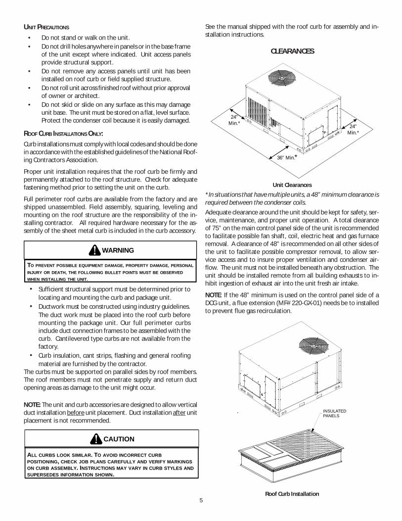
CLEARANCES
24”Min.* 24”
Min.*
36” Min.*
Unit Clearances
*In situations that have multiple units, a 48” minimum clearance isrequired between the condenser coils.Adequate clearance around the unit should be kept for safety, ser-vice, maintenance, and proper unit operation. A total clearanceof 75” on the main control panel side of the unit is recommendedto facilitate possible fan shaft, coil, electric heat and gas furnaceremoval. A clearance of 48” is recommended on all other sides ofthe unit to facilitate possible compressor removal, to allow ser-vice access and to insure proper ventilation and condenser air-flow. The unit must not be installed beneath any obstruction. Theunit should be installed remote from all building exhausts to in-hibit ingestion of exhaust air into the unit fresh air intake.
NOTE: If the 48” minimum is used on the control panel side of aDCG unit, a flue extension (MF# 220-GX-01) needs be to installedto prevent flue gas recirculation.
INSULATEDPANELS
Roof Curb Installation

6
ROOF CURB POST-INSTALLATION CHECKSAfter installation, check the top of the curb, duct connection frameand duct flanges to make sure gasket has been applied properly.Gasket should be firmly applied to the top of the curb perimeter,duct flanges and any exposed duct connection frame. If gasket isloose, re-apply using strong weather resistant adhesive.
PROTRUSION
Inspect curb to ensure that none of the utility services (electric)routed through the curb protrude above the curb.
IF PROTRUSIONS EXIST, DO NO ATTEMPT TO SET UNIT ON CURB.
CAUTION
ROOF TOP DUCT CONNECTIONS
Install all duct connections on the unit before placing the unit onrooftop.
HORIZONTAL DISCHARGE
Refer to IOD-7006 included in the literature pack for installing hori-zontal duct covers.
Flexible duct connectors between the unit and ducts are recom-mended. Insulate and weatherproof all external ductwork andjoints as required and in accordance with local codes.
SUPPLY12”
17” 7 3/8”
11” 4 7/8””
25”
6 3/16”
REMOVE COVERS
Horizontal Discharge Duct Connections
RIGGING DETAILS
WARNING
TO PREVENT PROPERTY DAMAGE, THE UNIT SHOULD REMAIN IN AN UPRIGHTPOSITION DURING ALL RIGGING AND MOVING OPERATIONS. TO FACILITATELIFTING AND MOVING WHEN A CRANE IS USED, PLACE THE UNIT IN ANADEQUATE CABLE SLING.
IF UNITS ARE LIFTED TWO AT A TIME, THE FORK HOLES ON THE CONDENSER END OF THE UNIT MUST NOT BE USED. MINIMUM FORK LENGTH IS 42” TO PREVENT DAMAGE TO THE UNIT; HOWEVER, 48” IS RECOMMENDED.
CAUTION
Provisions for forks have been included in the unit base frame. Noother fork locations are approved.
WARNING
TO PREVENT POSSIBLE EQUIPMENT DAMAGE, PROPERTY DAMAGE, PERSONALINJURY OR DEATH, THE FOLLOWING BULLET POINTS MUST BE OBSERVEDWHEN INSTALLING THE UNIT.
• Unit must be lifted by the four lifting holes located at thebase frame corners.
• Lifting cables should be attached to the unit with shackles.• The distance between the crane hook and the top of the
unit must not be less than 60”.• Two spreader bars must span over the unit to prevent
damage to the cabinet by the lift cables. Spreader barsmust be of sufficient length so that cables do not come incontact with the unit during transport. Remove woodstruts mounted beneath unit base frame before settingunit on roof curb. These struts are intended to protectunit base frame from fork lift damage. Removal isaccomplished by extracting the sheet metal retainers andpulling the struts through the base of the unit. Refer torigging label on the unit.
Important: If using bottom discharge with roof curb, ductworkshould be attached to the curb prior to installing the unit. Ductworkdimensions are shown in Roof Curb Installation Instructions.
Refer to the Roof Curb Installation Instructions for proper curbinstallation. Curbing must be installed in compliance with the Na-tional Roofing Contractors Association Manual.
Lower unit carefully onto roof mounting curb. While rigging unit,center of gravity will cause condenser end to be lower than supplyair end.
7
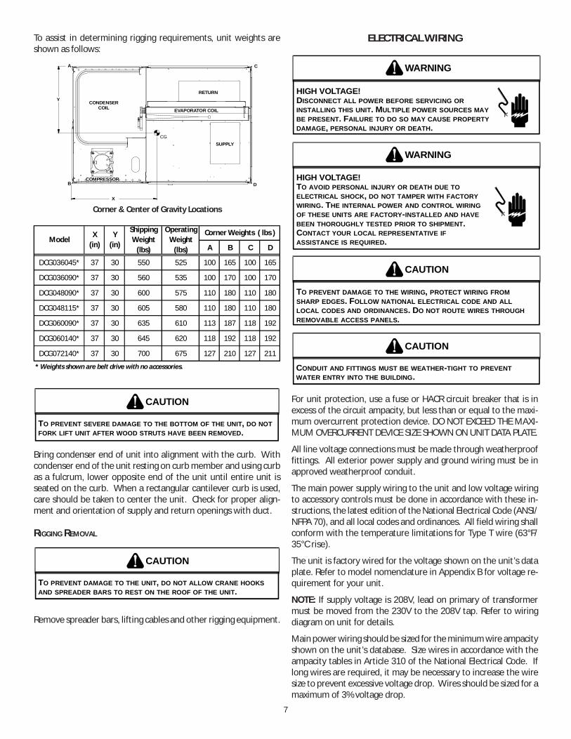
To assist in determining rigging requirements, unit weights areshown as follows:
A
B
C
D
CGSUPPLY
RETURN
EVAPORATOR COILCONDENSER
COIL
COMPRESSOR
Y
X
Corner & Center of Gravity Locations
A B C D
DCG036045* 37 30 550 525 100 165 100 165
DCG036090* 37 30 560 535 100 170 100 170
DCG048090* 37 30 600 575 110 180 110 180
DCG048115* 37 30 605 580 110 180 110 180
DCG060090* 37 30 635 610 113 187 118 192
DCG060140* 37 30 645 620 118 192 118 192
DCG072140* 37 30 700 675 127 210 127 211
Operating Weight
(lbs)
Corner Weights ( lbs )
* Weights shown are belt drive with no accessories.
ModelX
(in)Y
(in)
Shipping Weight
(lbs)
TO PREVENT SEVERE DAMAGE TO THE BOTTOM OF THE UNIT, DO NOT FORK LIFT UNIT AFTER WOOD STRUTS HAVE BEEN REMOVED.
CAUTION
Bring condenser end of unit into alignment with the curb. Withcondenser end of the unit resting on curb member and using curbas a fulcrum, lower opposite end of the unit until entire unit isseated on the curb. When a rectangular cantilever curb is used,care should be taken to center the unit. Check for proper align-ment and orientation of supply and return openings with duct.
RIGGING REMOVAL
TO PREVENT DAMAGE TO THE UNIT, DO NOT ALLOW CRANE HOOKS AND SPREADER BARS TO REST ON THE ROOF OF THE UNIT.
CAUTION
Remove spreader bars, lifting cables and other rigging equipment.
ELECTRICAL WIRING
HIGH VOLTAGE! DISCONNECT ALL POWER BEFORE SERVICING OR INSTALLING THIS UNIT. MULTIPLE POWER SOURCES MAY BE PRESENT. FAILURE TO DO SO MAY CAUSE PROPERTY DAMAGE, PERSONAL INJURY OR DEATH.
WARNING
HIGH VOLTAGE! TO AVOID PERSONAL INJURY OR DEATH DUE TO ELECTRICAL SHOCK, DO NOT TAMPER WITH FACTORY WIRING. THE INTERNAL POWER AND CONTROL WIRING OF THESE UNITS ARE FACTORY-INSTALLED AND HAVE BEEN THOROUGHLY TESTED PRIOR TO SHIPMENT. CONTACT YOUR LOCAL REPRESENTATIVE IF ASSISTANCE IS REQUIRED.
WARNING
TO PREVENT DAMAGE TO THE WIRING, PROTECT WIRING FROM SHARP EDGES. FOLLOW NATIONAL ELECTRICAL CODE AND ALL LOCAL CODES AND ORDINANCES. DO NOT ROUTE WIRES THROUGH REMOVABLE ACCESS PANELS.
CAUTION
CONDUIT AND FITTINGS MUST BE WEATHER-TIGHT TO PREVENT WATER ENTRY INTO THE BUILDING.
CAUTION
For unit protection, use a fuse or HACR circuit breaker that is inexcess of the circuit ampacity, but less than or equal to the maxi-mum overcurrent protection device. DO NOT EXCEED THE MAXI-MUM OVERCURRENT DEVICE SIZE SHOWN ON UNIT DATA PLATE.
All line voltage connections must be made through weatherprooffittings. All exterior power supply and ground wiring must be inapproved weatherproof conduit.
The main power supply wiring to the unit and low voltage wiringto accessory controls must be done in accordance with these in-structions, the latest edition of the National Electrical Code (ANSI/NFPA 70), and all local codes and ordinances. All field wiring shallconform with the temperature limitations for Type T wire (63°F/35°C rise).
The unit is factory wired for the voltage shown on the unit’s dataplate. Refer to model nomenclature in Appendix B for voltage re-quirement for your unit.
NOTE: If supply voltage is 208V, lead on primary of transformermust be moved from the 230V to the 208V tap. Refer to wiringdiagram on unit for details.
Main power wiring should be sized for the minimum wire ampacityshown on the unit’s database. Size wires in accordance with theampacity tables in Article 310 of the National Electrical Code. Iflong wires are required, it may be necessary to increase the wiresize to prevent excessive voltage drop. Wires should be sized for amaximum of 3% voltage drop.
8
CAUTION
TO AVOID PROPERTY DAMAGE OR PERSONAL INJURY DUE TO FIRE, USEONLY COPPER CONDUCTORS.
CAUTION
TO PREVENT IMPROPER AND DANGEROUS OPERATION DUE TO WIRING ERRORS,LABEL ALL WIRES PRIOR TO DISCONNECTION WHEN SERVICING CONTROLS.VERIFY PROPER OPERATION AFTER SERVICING.
NOTE: A weather-tight disconnect switch, properly sized for theunit total load, must be field or factory installed. An external fieldsupplied disconnect may be mounted on the exterior panel.
Ensure the data plate is not covered by the field-supplieddisconnect switch.
• Some disconnect switches are not fused. Protect thepower leads at the point of distribution in accordance withthe unit data plate.
• The unit must be electrically grounded in accordance withlocal codes or, in the absence of local codes, with the latestedition of the National Electrical Code (ANSI-NFPA 70). Aground lug is provided for this purpose. Size groundingconductor in accordance with Table 250-95 of the NationalElectrical Code. Do not use the ground lug for connectinga neutral conductor.
• Connect power wiring to the compressor contactor closestto the entrance located within the main control box or toelectrical power block, if equipped.
LOW VOLTAGEBLOCK
MAIN POWER
LOW VOLTAGEENTRANCE POWER THRU
THE CURB
Power and Low Voltage Block Connections
FAILURE OF UNIT DUE TO OPERATION ON IMPROPER LINE VOLTAGE OR WITH EXCESSIVE PHASE UNBALANCE CONSTITUTES PRODUCT ABUSE AND WILL VOID YOUR WARRANTY AND MAY CAUSE SEVERE DAMAGE TO THE UNIT ELECTRICAL COMPONENTS.
WARNING
Areas Without Convenience Outlet
It is recommended that an independent 115V power source bebrought to the vicinity of the roof top unit for portable lights andtools used by the service mechanic.
NOTE: Refer to local codes for requirements. These outlets canalso be factory installed.
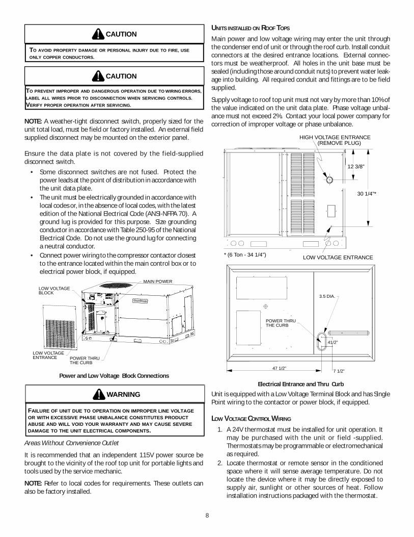
UNITS INSTALLED ON ROOF TOPS
Main power and low voltage wiring may enter the unit throughthe condenser end of unit or through the roof curb. Install conduitconnectors at the desired entrance locations. External connec-tors must be weatherproof. All holes in the unit base must besealed (including those around conduit nuts) to prevent water leak-age into building. All required conduit and fittings are to be fieldsupplied.
Supply voltage to roof top unit must not vary by more than 10% ofthe value indicated on the unit data plate. Phase voltage unbal-ance must not exceed 2%. Contact your local power company forcorrection of improper voltage or phase unbalance.
HIGH VOLTAGE ENTRANCE
LOW VOLTAGE ENTRANCE1:4
30 1/4”*
12 3/8”
(REMOVE PLUG)
* (6 Ton - 34 1/4”)
4 1/2”
47 1/2” 7 1/2”
POWER THRUTHE CURB
3.5 DIA.
Electrical Entrance and Thru Curb
Unit is equipped with a Low Voltage Terminal Block and has SinglePoint wiring to the contactor or power block, if equipped.
LOW VOLTAGE CONTROL WIRING
1. A 24V thermostat must be installed for unit operation. Itmay be purchased with the unit or field -supplied.Thermostats may be programmable or electromechanicalas required.
2. Locate thermostat or remote sensor in the conditionedspace where it will sense average temperature. Do notlocate the device where it may be directly exposed tosupply air, sunlight or other sources of heat. Followinstallation instructions packaged with the thermostat.

9
3. Use #18 AWG wire for 24V control wiring runs notexceeding 75 feet. Use #16 AWG wire for 24V control wiringruns not exceeding 125 feet. Use #14 AWG wire for 24Vcontrol wiring runs not exceeding 200 feet. Low voltagewiring may be National Electrical Code (NEC) Class 2 wherepermitted by local codes.
4. Route thermostat wires from sub-base terminals to theunit. Control wiring should enter through the condenserpanel opening or through curb indicated in “ElectricalEntrance” figure. Connect thermostat and any accessorywiring to low voltage terminal block TB1 in the main controlbox.
NOTE: Field-supplied conduit may need to be installed dependingon unit/curb configuration. Use #18 AWG solid conductor wirewhenever connecting thermostat wires to terminals on sub-base.DO NOT use larger than #18 AWG wire. A transition to #18 AWGwire may be required before entering thermostat sub-base.
NOTE: Refer to unit wiring diagrams for thermostat hookups.
GAS SUPPLY PIPING
TO PREVENT PERSONAL INJURY OR DEATH DUE TO IMPROPER INSTALLATION, ADJUSTMENT, ALTERATION, SERVICE OR MAINTENANCE, REFER TO THIS MANUAL. FOR ADDITIONAL ASSISTANCE OR INFORMATION, CONSULT A QUALIFIED INSTALLER, SERVICE AGENCY OR THE GAS SUPPLIER.
WARNING
IMPORTANT NOTE: This unit is factory set to operate on naturalgas at the altitudes shown on the rating plate.
TO AVOID PROPERTY DAMAGE, PERSONAL INJURY OR DEATH WHEN EITHER USING PROPANE GAS ALONE OR AT HIGHER ALTITUDES, OBTAIN AND INSTALL THE PROPER CONVERSION KIT(S). FAILURE TO DO SO CAN RESULT IN UNSATISFACTORY OPERATION AND/OR EQUIPMENT DAMAGE. HIGH ALTITUDE KITS ARE FOR U.S. INSTALLATIONS ONLY AND ARE NOT APPROVED FOR USE IN CANADA.
WARNING
The rating plate is stamped with the model number, type of gasand gas input rating. Make sure the unit is equipped to operate onthe type of gas available. Conversion to propane (LP) gas is permit-ted with the use of the factory authorized conversion kit (see theunit Technical Manual for the appropriate kit). For High Altitudederates, refer to the latest edition of the National Fuel Gas CodeNFPA 54/ANSI Z223.1.
NATURAL Min. 5.0" W.C., Max. 10.0" W.C.
PROPANE Min. 11.0" W.C., Max. 14.0" W.C.
INLET GAS PRESSURE
Inlet Gas Pressure Must Not Exceed the Maximum Value Shown in Table Above.
The minimum supply pressure should not vary from that shown inthe table above because this could prevent the unit from havingdependable ignition. In addition, gas input to the burners mustnot exceed the rated input shown on the rating plate. Overfiringof the unit could result in premature heat exchanger failure.
PIPING
IMPORTANT NOTE: To avoid possible unsatisfactory operation orequipment damage due to under firing of equipment, do not un-dersize the natural/propane gas piping from the meter/tank to theunit. When sizing a trunk line, include all appliances on that linethat could be operated simultaneously.
The rating plate is stamped with the model number, type of gasand gas input rating. Make sure the unit is equipped to operate onthe type of gas available. The gas line installation must complywith local codes, or in the absence of local codes, with the latestedition of the National Fuel Gas Code NFPA 54/ANSI Z223.1.
Natural Gas Connection
1/2 3/4 1 1 1/4 1 1 /210 132 278 520 1050 160020 92 190 350 730 110030 73 152 285 590 98040 63 130 245 500 76050 56 115 215 440 67060 50 105 195 400 61070 46 96 180 370 56080 43 90 170 350 53090 40 84 160 320 490
100 38 79 150 305 460Pressure= .50 PSIG or less and Pressure Drop of 0.3" W.C.(Based on 0.60 Specific Gravity Gas)
Natural Gas Capacity of Pipein Cubic Feet of Gas Per Hour (CFH)
Nominal Black Pipe Size (inches)Length ofPipe in Feet
Heating Value of Gas (BTU/Cubic FootCFH =
BTUH Furnace Input
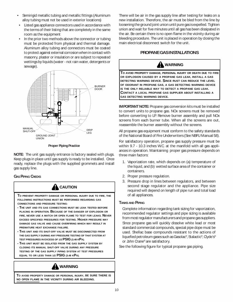
Refer to the Proper Piping Practice drawing for the general layoutat the unit. The following rules apply:
1. Use black iron pipe and fittings for the supply piping. Theuse of a flex connector and/or copper piping is permittedas long as it is in agreement with local codes.
2. Use pipe joint compound on male threads only. Pipe jointcompound must be resistant to the action of the fuel used.
3. Use ground joint unions.4. Install a drip leg to trap dirt and moisture before it can
enter the gas valve. The drip leg must be a minimum ofthree inches long.
5. Use two pipe wrenches when making connection to thegas valve to keep it from turning.
6. Install a manual shut-off valve in a convenient location(within six feet of unit) between the meter and the unit.
7. Tighten all joints securely.8. The unit must be connected to the building piping by one
of the following methods:• Rigid metallic pipe and fittings
10
• Semirigid metallic tubing and metallic fittings (Aluminumalloy tubing must not be used in exterior locations)
• Listed gas appliance connectors used in accordance withthe terms of their listing that are completely in the sameroom as the equipment
• In the prior two methods above the connector or tubingmust be protected from physical and thermal damage.Aluminum alloy tubing and connectors must be coatedto protect against external corrosion when in contact withmasonry, plaster or insulation or are subject to repeatedwettings by liquids (water - not rain water, detergents orsewage).
BURNERDOOR
DRIPLEG
MANUALSHUT-OFF
GROUND JOINTUNION
TBD
Proper Piping Practice
NOTE: The unit gas supply entrance is factory sealed with plugs.Keep plugs in place until gas supply is ready to be installed. Onceready, replace the plugs with the supplied grommets and installgas supply line.
GAS PIPING CHECKS
CAUTION
TO PREVENT PROPERTY DAMAGE OR PERSONAL INJURY DUE TO FIRE, THEFOLLOWING INSTRUCTIONS MUST BE PERFORMED REGARDING GASCONNECTIONS AND PRESSURE TESTING: • THE UNIT AND ITS GAS CONNECTIONS MUST BE LEAK TESTED BEFORE PLACING IN OPERATION. BECAUSE OF THE DANGER OF EXPLOSION OR FIRE, NEVER USE A MATCH OR OPEN FLAME TO TEST FOR LEAKS. NEVER EXCEED SPECIFIED PRESSURES FOR TESTING. HIGHER PRESSURE MAY DAMAGE GAS VALVE AND CAUSE OVERFIRING WHICH MAY RESULT IN PREMATURE HEAT EXCHANGE FAILURE.• THIS UNIT AND ITS SHUT-OFF VALVE MUST BE DISCONNECTED FROM THE GAS SUPPLY DURING ANY PRESSURE TESTING OF THAT SYSTEM AT TEST PRESSURES IN EXCESS OF 1/2 PSIG (3.48 KPA).• THIS UNIT MUST BE ISOLATED FROM THE GAS SUPPLY SYSTEM BY CLOSING ITS MANUAL SHUT-OFF VALVE DURING ANY PRESSURE TESTING OF THE GAS SUPPLY PIPING SYSTEM AT TEST PRESSURES EQUAL TO OR LESS THAN 1/2 PSIG (3.48 KPA).
WARNING
TO AVOID PROPERTY DAMAGE OR PERSONAL INJURY, BE SURE THERE ISNO OPEN FLAME IN THE VICINITY DURING AIR BLEEDING.
There will be air in the gas supply line after testing for leaks on anew installation. Therefore, the air must be bled from the line byloosening the ground joint union until pure gas is expelled. Tightenunion and wait for five minutes until all gas has been dissipated inthe air. Be certain there is no open flame in the vicinity during airbleeding procedure. The unit is placed in operation by closing themain electrical disconnect switch for the unit.
PROPANE GAS INSTALLATIONS
WARNING
TO AVOID PROPERTY DAMAGE, PERSONAL INJURY OR DEATH DUE TO FIREOR EXPLOSION CAUSED BY A PROPANE GAS LEAK, INSTALL A GASDETECTING WARNING DEVICE. SINCE RUST CAN REDUCE THE LEVELOF ODORANT IN PROPANE GAS, A GAS DETECTING WARNING DEVICEIS THE ONLY RELIABLE WAY TO DETECT A PROPANE GAS LEAK. CONTACT A LOCAL PROPANE GAS SUPPLIER ABOUT INSTALLING AGAS DETECTING WARNING DEVICE.
IMPORTANT NOTE: Propane gas conversion kits must be installedto convert units to propane gas. NOx screens must be removedbefore converting to LP. Remove burner assembly and pull NOxscreens from each burner tube. When all the screens are out,reassemble the burner assembly without the screens.
All propane gas equipment must conform to the safety standardsof the National Board of Fire Underwriters (See NBFU Manual 58).For satisfactory operation, propane gas supply pressure must bewithin 9.7 - 10.3 inches W.C. at the manifold with all gas appli-ances in operation. Maintaining proper gas pressure depends onthree main factors:
1. Vaporization rate, which depends on (a) temperature ofthe liquid, and (b) wetted surface area of the container orcontainers.
2. Proper pressure regulation.3. Pressure drop in lines between regulators, and between
second stage regulator and the appliance. Pipe sizerequired will depend on length of pipe run and total loadof all appliances.
TANKS AND PIPING
Complete information regarding tank sizing for vaporization,recommended regulator settings and pipe sizing is availablefrom most regulator manufacturers and propane gas suppliers.Since propane gas will quickly dissolve white lead or moststandard commercial compounds, special pipe dope must beused. Shellac base compounds resistant to the actions ofliquefied petroleum gases such as Gasolac®, Stalactic®, Clyde’s®
or John Crane® are satisfactory.See the following figure for typical propane gas piping.

11
200 PSIGMaximum
5 to 15 PSIG(20 PSIG Max.)
Continuous11" W.C.
Second StageRegulator
First StageRegulator
Typical Propane Gas Piping
ROOF TOP LOCATION AND INSTALLATION
The gas supply piping location and installation for roof top unitsmust be in accordance with local codes or, in the absence of localscodes, with ordinances of the latest edition of the National FuelGas Code (ANSI Z223.1).
A manual gas shut off valve must be field installed external to theroof top unit. In addition, a drip leg must be installed near theinlet connection. A ground joint union connection is required be-tween the external shut off valve and the unit connection to thegas valve to permit removal of the burner assembly for servicing.
1. Route gas piping to unit so that it does not interfere withthe removal of access panels. Support and align piping toprevent strains or misalignment of the manifold assembly.
2. All units are furnished with standard female NPT pipeconnections. Connection pipe sizes for DCG036 through072 units is 1/2" NPT on 045 to 140 mBH units. The size ofthe gas supply piping to the unit must be based on lengthof run, number of units on the system, gas characteristics,BTU requirement and available supply pressure. All pipingmust be done in accordance with local codes or, in theabsence of local codes, with the latest edition of theNational Fuel Gas Code (ANSI Z223.1).NOTE: The gas connection size at the unit does NOTestablish the size of the supply line.
3. These units are designed for either natural or propane(LP) gas and are specifically constructed at the factory foronly one of these fuels. The fuels are NOT interchangeable.However, the furnace can be converted in the field fromnatural gas to LP gas with the appropriate factory kit (seeunit Technical Manual for the appropriate kit). Only aqualified contractor, experienced with natural and propanegas systems, should attempt conversion. Kit instructionsmust be followed closely to assure safe and reliable unitoperation.
4. With all units on a common line operating under full fire,natural gas main supply pressure should be adjusted toapproximately 7.0" w.c., measured at the unit gas valve. Ifthe gas pressure at the unit is greater than 10.5" w.c., thecontractor must furnish and install an external typepositive shut off service pressure regulator. The unit willnot function satisfactorily if supply gas pressure is less than5.5" w.c. or greater than 10.5" w.c..NOTE: A minimum horizontal distance of 48" between
the regulator and the furnace flue discharge is required.5. With all units on a common line operating under full LP
gas main supply pressure should be at least 11.0" w.c. andmust be no greater than 13.0" w.c., measured at the unitgas valve. Unit will not function satisfactorily if supply gaspressure is less than 11.0" w.c. or greater than 13.0" w.c..
6. All pipe connections should be sealed with a pipe threadcompound, which is resistant to the fuel used with thefurnace. A soapy water solution should be used to checkall joints for leaks. A tap is located on the entering side ofthe gas valve for test gauge connection to measure supply(main) gas pressure. Another tap is provided on themanifold side of the gas valve for checking manifoldpressure.
THIS UNIT AND ITS INDIVIDUAL SHUTOFF VALVE MUST BE DISCONNECTED FROM THE GAS SUPPLY SYSTEM DURING ANY PRESSURE TESTING OF THAT SYSTEM AT TEST PRESSURES IN EXCESS OF 1/2 PSIG (13.8” W.C.).
WARNING
THIS UNIT MUST BE ISOLATED FROM THE GAS SUPPLY PIPING SYSTEM BY CLOSING ITS INDIVIDUAL MANUAL SHUTOFF VALVE DURING ANY PRESSURE TESTING EQUAL TO OR LESS THAN 1/2 PSIG.
CAUTION
7. There must be no obstruction to prevent the flow ofcombustion and ventilating air. A vent stack is not requiredand must never be used. The power venter will supply anadequate amount of combustion air as long as the airpassageways are kept free of any obstructions and therecommended external unit clearances are maintained.
CIRCULATING AIR AND FILTERS
DUCTWORK
The supply duct from the unit through a wall may be installed with-out clearance. However, minimum unit clearances must be main-tained (see “Clearances” section). The supply duct should be pro-vided with an access panel large enough to inspect the air cham-ber downstream of the heat exchanger. A cover should be tightlyattached to prevent air leaks.
Ductwork dimensions are shown in the roof curb installationmanual.
If desired, supply and return duct connections to the unit may bemade with flexible connections to reduce possible unit operatingsound transmission.

12
VENTING
NOTE: Venting is self-contained.
The indoor motor on DCG units are dual voltage motors. They arefactory wired for 230 volts. If field supply power is 208V, theinstaller must swap the connections to the black and red loads(located in the blower compartment) to ensure correct inductormotor operation.
CONDENSATE DRAIN CONNECTION
CONDENSATE DRAIN CONNECTION
A 3/4” female NPT drain connection is supplied on the end of theunit and bottom of the drain pan for condensate piping. An exter-nal trap must be installed for proper condensate drainage.
DRAINCONNECTION
UNIT 2" MINIMUM
FLEXIBLETUBING-HOSEOR PIPE
3" MINIMUM
A POSITIVE LIQUIDSEAL IS REQUIRED
Drain Connection
Install condensate drain trap as shown. Use 3/4" drain line andfittings or larger. Do not operate without trap.
HORIZONTAL DRAIN
Drainage of condensate directly onto the roof may be acceptable;refer to local code. It is recommended that a small drip pad ofeither stone, mortar, wood or metal be provided to prevent anypossible damage to the roof.
CLEANING
Due to the fact that drain pans in any air conditioning unitwill have some moisture in them, algae and fungus willgrow due to airborne bacteria and spores. Periodic clean-ing is necessary to prevent this build-up from plugging thedrain.
STARTUP, ADJUSTMENTS, AND CHECKS
HIGH VOLTAGE!
OND THE FRAME OF THIS UNIT TO THE BUILDING ELECTRICAL GROUND BY USE OF THE GROUNDING TERMINAL PROVIDED OR OTHER ACCEPTABLE MEANS. DISCONNECT ALL POWER BEFORE SERVICING OR INSTALLING THIS UNIT.
TO AVOID PERSONAL INJURY OR DEATH DUE TO ELECTRICAL SHOCK, B
WARNING
PRE-STARTUP INSTRUCTIONS - GENERAL
TO PREVENT PROPERTY DAMAGE OR PERSONAL INJURY, DO NOT START THE UNIT UNTIL ALL NECESSARY PRE-CHECKS AND TESTS HAVE BEEN PERFORMED.
CAUTION
Prior to the beginning of Startup, Adjustments, and Checks proce-dures, the following steps should be completed in the building.
MOVING MACHINERY HAZARD!TO PREVENT POSSIBLE PERSONAL INJURY OR DEATH, DISCONNECT POWER TO THE UNIT AND PADLOCK IN THE “OFF” POSITION BEFORE SERVICNG FANS.
WARNING
This unit is equipped with an electronic ignition device to auto-matically light the main burners. It also has a power vent blowerto exhaust combustion products.
On new installations, or if a major component has been replaced,the operation of the unit must be checked.
Check unit operation as outlined in the following instructions. Ifany sparking, odors, or unusual sounds are encountered, shut offelectrical power and recheck for wiring errors, or obstructions inor near the blower motors. Duct covers must be removed beforeoperating unit.
The Startup, Adjustments, and Checks procedure provides a step-by-step sequence which, if followed, will assure the proper startupof the equipment in the minimum amount of time. Air balancingof duct system is not considered part of this procedure. However,it is an important phase of any air conditioning system startup andshould be performed upon completion of the Startup, Adjustments,and Checks procedure. The Startup, Adjustments, and Checks pro-cedure at outside ambients below 55°F should be limited to a readi-ness check of the refrigeration system with the required final checkand calibration left to be completed when the outside ambientrises above 55°F.
TEMPORARY HEATING OR COOLING
If the unit is to be used for temporary heating or cooling, a “Startup,Adjustments, and Checks” must first be performed in accordancewith this manual. Failure to comply with this requirement will voidthe warranty. After the machines are used for temporary heatingor cooling, inspect the coils, fans, and motors for unacceptablelevels of construction dust and dirt and install new filters.
CONTRACTOR RESPONSIBILITY
The installing contractor must be certain that:
• All supply and return air ductwork is in place, properlysealed, and corresponds with installation instructions.
• All thermostats are mounted and wired in accordancewith installation instructions.
13
• All electric power, all gas, hot water or steam lineconnections, and the condensate drain installation havebeen made to each unit on the job. These main supplylines must be functional and capable of operating all unitssimultaneously.
• Requirements are met for venting and combution air.• Air filters are in place.• Input rate and temperature rise are adjusted per rating
plate.
ROOF CURB INSTALLATION CHECK
Inspect the roof curb for correct installation. The unit and curbassembly should be level. Inspect the flashing of the roof mount-ing curb to the roof, especially at the corners, for good workman-ship. Also check for leaks around gaskets. Note any deficiencies ina separate report and forward to the contractor.
OBSTRUCTIONS, FAN CLEARANCE AND WIRING
Remove any extraneous construction and shipping materials thatmay be found during this procedure. Rotate all fans manually tocheck for proper clearances and that they rotate freely. Check forbolts and screws that may have jarred loose during shipment tothe job site. Retighten if necessary. Re-tighten all electrical con-nections.
FIELD DUCT CONNECTIONS
Verify that all duct connections are tight and that there is no airbypass between supply and return.
FILTER SECTION CHECK
Remove filter section access panels and check that filters are prop-erly installed. Note airflow arrows on filter frames.
PRE-STARTUP PRECAUTIONS
It is important to your safety that the unit has been properlygrounded during installation. Check ground lug connection in maincontrol box for tightness prior to closing circuit breaker or discon-nect switch. Verify that supply voltage on line side of disconnectagrees with voltage on unit identification plate and is within theutilization voltage range as indicated in Appendix B Electrical Data.
System Voltage - That nominal voltage value assigned to a circuitor system for the purpose of designating its voltage class.
Nameplate Voltage - That voltage assigned to a piece of equip-ment for the purpose of designating its voltage class and for thepurpose of defining the minimum and maximum voltage at whichthe equipment will operate.
Utilization Voltage - The voltage of the line terminals of the equip-ment at which the equipment must give fully satisfactory perfor-mance. Once it is established that supply voltage will be main-tained within the utilization range under all system conditions,check and calculate if an unbalanced condition exists betweenphases. Calculate percent voltage unbalance as follows.
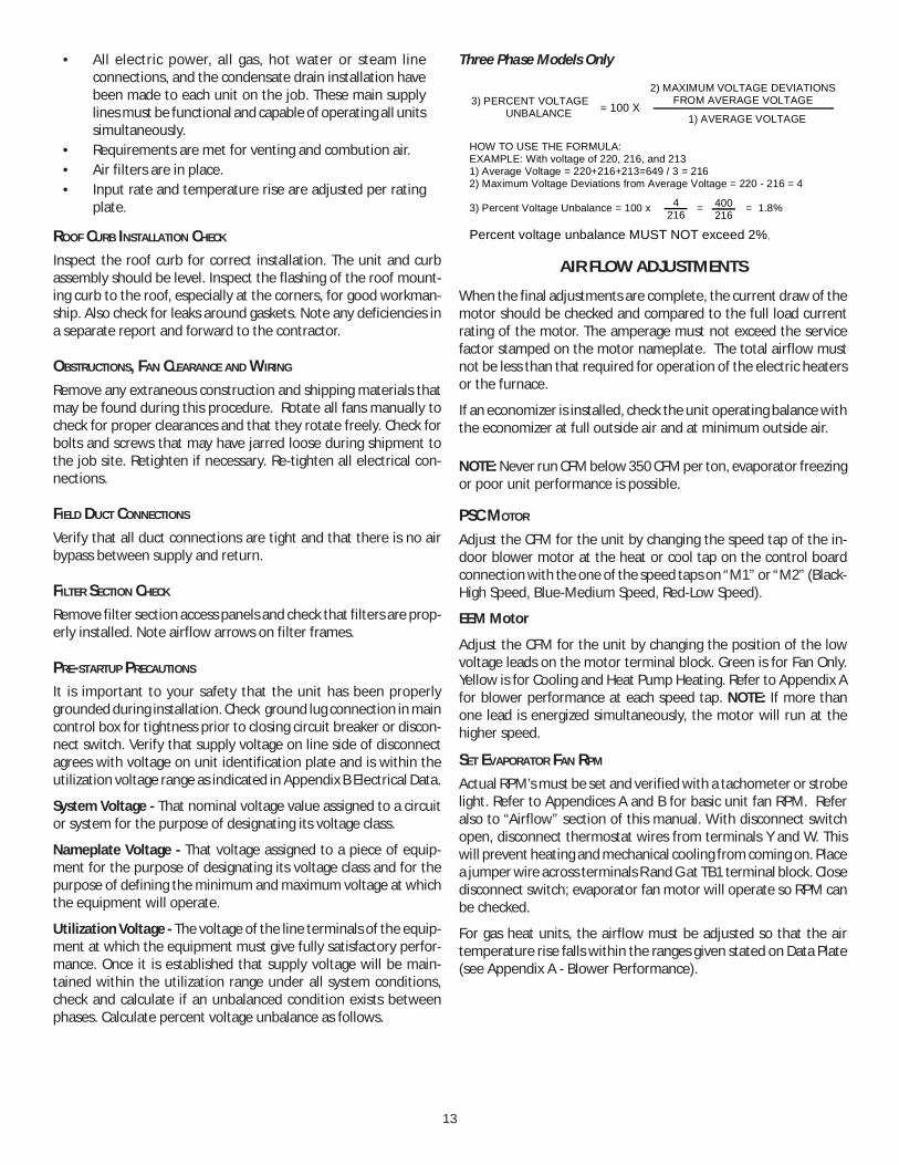
Three Phase Models Only
3) PERCENT VOLTAGE UNBALANCE
2) MAXIMUM VOLTAGE DEVIATIONSFROM AVERAGE VOLTAGE
1) AVERAGE VOLTAGE
HOW TO USE THE FORMULA:EXAMPLE: With voltage of 220, 216, and 2131) Average Voltage = 220+216+213=649 / 3 = 2162) Maximum Voltage Deviations from Average Voltage = 220 - 216 = 4
3) Percent Voltage Unbalance = 100 x = = 1.8%
Percent voltage unbalance MUST NOT exceed 2%.
4216
400216
= 100 X
AIR FLOW ADJUSTMENTS
When the final adjustments are complete, the current draw of themotor should be checked and compared to the full load currentrating of the motor. The amperage must not exceed the servicefactor stamped on the motor nameplate. The total airflow mustnot be less than that required for operation of the electric heatersor the furnace.
If an economizer is installed, check the unit operating balance withthe economizer at full outside air and at minimum outside air.
NOTE: Never run CFM below 350 CFM per ton, evaporator freezingor poor unit performance is possible.
PSC MOTOR
Adjust the CFM for the unit by changing the speed tap of the in-door blower motor at the heat or cool tap on the control boardconnection with the one of the speed taps on “M1” or “M2” (Black-High Speed, Blue-Medium Speed, Red-Low Speed).
EEM Motor
Adjust the CFM for the unit by changing the position of the lowvoltage leads on the motor terminal block. Green is for Fan Only.Yellow is for Cooling and Heat Pump Heating. Refer to Appendix Afor blower performance at each speed tap. NOTE: If more thanone lead is energized simultaneously, the motor will run at thehigher speed.
SET EVAPORATOR FAN RPM
Actual RPM’s must be set and verified with a tachometer or strobelight. Refer to Appendices A and B for basic unit fan RPM. Referalso to “Airflow” section of this manual. With disconnect switchopen, disconnect thermostat wires from terminals Y and W. Thiswill prevent heating and mechanical cooling from coming on. Placea jumper wire across terminals R and G at TB1 terminal block. Closedisconnect switch; evaporator fan motor will operate so RPM canbe checked.
For gas heat units, the airflow must be adjusted so that the airtemperature rise falls within the ranges given stated on Data Plate(see Appendix A - Blower Performance).
14
EVAPORATOR FAN ROTATION CHECK (THREE PHASE MODELS ONLY)Check that fan rotates clockwise when viewed from the drive sideof unit and in accordance with rotation arrow shown on blowerhousing. If it does not, reverse any two incoming power cables atSingle Point Power Block. In this case, repeat bearing check.
Do not attempt to change load side wiring. Internal wiring assuresall motors and compressors will rotate in correct direction onceevaporator fan motor rotation check has been made.
ELECTRICAL INPUT CHECK
Make preliminary check of evaporator fan ampere draw and verifythat motor nameplate amps are not exceeded. A final check ofamp draw should be made upon completion of air balancing ofthe duct system (see Appendix C).
BELT DRIVE MODELS ONLYThe drive on the supply fan is typically set in the middle of theRPM range. The drive motor sheave pitch diameter is field adjust-able for the required airflow. Refer to “Motor Sheave Adjustmens”section.
Upon completion of the air flow balancing, we recommend re-placing the variable pitched motor sheave with a properly-sizedfixed sheave. A matching fixed sheave will provide longer belt andbearing life and vibration free operation. Initially, it is best to havea variable pitched motor sheave for the purpose of airflow balanc-ing, but once the balance has been achieved, fixed sheaves main-tain alignment and minimize vibration more effectively. For directdrive units, move fan speed wire.
BEARING CHECK
Prior to energizing any fans, check and make sure that all setscrewsare tight so that bearings are properly secured to shafts.
TENSION AND ALIGNMENT ADJUSTMENT
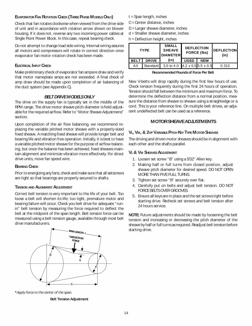
Correct belt tension is very important to the life of your belt. Tooloose a belt will shorten its life; too tight, premature motor andbearing failure will occur. Check you belt drive for adequate “run-in” belt tension by measuring the force required to deflect thebelt at the midpoint of the span length. Belt tension force can bemeasured using a belt tension gauge, available through most beltdrive manufacturers.
SPAN LENGTH t*DEFLECTION
FORCE
h
C
dH
D
*Apply force to the center of the span.
Belt Tension Adjustment
t = Span length, inchesC = Center distance, inchesD = Larger sheave diameter, inchesd = Smaller sheave diameter, inchesh = Deflection height, inches
BELT DRIVE USED NEWAX Standard 3.0 to 4.0 4.2 ± 0.5 5.5 ± 0.5 0.313
DEFLECTION FORCE (lbs)TYPE DEFLECTION
(in)
SMALLSHEAVE
DIAMETER(in)
Recommended Pounds of Force Per Belt
New V-belts will drop rapidly during the first few hours of use.Check tension frequently during the first 24 hours of operation.Tension should fall between the minimum and maximum force. Todetermine the deflection distance from a normal position, mea-sure the distance from sheave to sheave using a straightedge or acord. This is your reference line. On multiple belt drives, an adja-cent undeflected belt can be used as a reference.
MOTOR SHEAVE ADJUSTMENTS
VL, VM, & 2VP VARIABLE PITCH KEY TYPE MOTOR SHEAVES
The driving and driven motor sheaves should be in alignment witheach other and the shafts parallel.
VL & VM SHEAVES ADJUSTMENT
1. Loosen set screw “B” using a 5/32" Allen key.2. Making half or full turns from closed position, adjust
sheave pitch diameter for desired speed. DO NOT OPENMORE THAN FIVE FULL TURNS.
3. Tighten set screw “B” securely over flat.4. Carefully put on belts and adjust belt tension. DO NOT
FORCE BELTS OVER GROOVES.5. Ensure all keys are in place and the set screws tight before
starting drive. Recheck set screws and belt tension after24 hours service.
NOTE: Future adjustments should be made by loosening the belttension and increasing or decreasing the pitch diameter of thesheave by half or full turns as required. Readjust belt tension beforestarting drive.

15
C
B
VL & VM
NOTE: Do NOT operate sheave with flange projecting beyondthe hub end.
GAS SYSTEM CHECK
Pre-Operation Checks
1. Close the manual gas valve external to the unit.2. Turn off the electrical power supply to the unit.3. Set the room thermostat to its lowest possible setting.4. Remove the heat exchanger door on the side of the unit
by removing screws.5. This unit is equipped with an ignition device which
automatically lights the main burner. DO NOT try to lightburner by any other method.
6. Move the gas control valve switch to the OFF position. Donot force.
7. Wait five minutes to clear out any gas.8. Smell for gas, including near the ground. This is important
because some types of gas are heavier than air. If you havewaited five minutes and you do smell gas, immediatelyfollow the warnings on page 3 of this manual. If havingwaited for five minutes and no gas smell is noted, movethe gas control valve switch to the ON position.
9. Replace the heat exchanger door on the side of the unit.10. Open the manual gas valve external to the unit.11. Turn on the electrical power supply to the unit.12. Set the thermostat to desired setting.
GAS SUPPLY PRESSURES & REGULATOR ADJUSTMENTS
SHOULD OVERHEATING OCCUR OR THE GAS SUPPLY FAIL TO SHUT OFF, TURN OFF THE MANUAL GAS SHUTOFF VALVE EXTERNAL TO THE UNIT BEFORE TURNING OFF THE ELECTRICAL SUPPLY.
WARNING
TO AVOID PROPERTY DAMAGE, PERSONAL INJURY OR DEATH, DO NOT FIRE GAS UNIT WITH FLUE BOX COVER REMOVED.
WARNING
NOTE: Except during brief periods when gas pressures are beingmeasured by qualified service personnel, the furnace access panelmust always be secured in place when the furnace is in operation.An inspection port in the access panel is provided to monitor theflame.The first step in checking out the gas-fired furnace is to test thegas supply piping to the unit for tightness and purge the system ofair using methods outlined in the latest edition of the NationalFuel Gas Code ANSI Z223.1. Verify that the disconnect switch is inthe “OFF” position. A soapy water solution should be used to checkfor gas leaks. Since the unit is subject to considerable jarring dur-ing shipment, it is extremely important that all gas connectionsand joints be tested for tightness. Gas piping downstream fromthe unit inlet should be checked for leaks during the subsequentsequence check.
The supply gas pressure should be adjusted to 7.0" w.c. on naturalgas and 11.0" on LP gas with the gas burners operating. If there ismore than one unit on a common gas line, the pressures shouldbe checked with all units under full fire. A supply pressure tap isprovided on the upstream side of the gas valve. A manifold pres-sure tap is provided on the gas valve. The normal manifold pres-sure for full input is 3.5" w.c. on natural gas and 9.5" w.c. for pro-pane gas. Low fire natural gas 2.0” w.c., 6.0” low fire propane gas.Minimum gas supply pressure is 5.5" w.c. for natural gas and 11.0"for propane gas. In order to obtain rating, gas supply pressure mustbe 11.0" w.c. for propane gas.
The pressure regulator on LP gas models is adjusted for 9.5" w.c.manifold pressure and is intended to prevent over-firing only. Donot attempt adjustment of the built-in pressure regulator unlessthe supply pressure is at least 7.0" w.c. on natural gas or 13.0" w.c.on propane gas. Check the location of the ignition electrode andthe flame sensor for correct gap setting.
FLAMESENSOR
Flame Sensor and Ignition Electrode Location

16
NATURAL (Dia)
PROPANE (LP)(Dia)
45,000 2 23,000 #43 #55
115,000 5 23,000 #43 #55
140,000 6 23,000 #43 #55
90,000 4 23,000 #43 #55
GAS ORIFICESMAXIMUM INPUT (BTUH)
NUMBERof
BURNERS
MAXIMUMBTUH/BURNER
Heat Exchanger and Burner Orifice Specifications
NOTE: Gas appliances located more than 2000 feet above sea levelmust be derated 4% per 1000 feet of total elevation and thatvariance in gas heating value and specific gravity require changein manifold pressure to obtain rating, it is mandatory that the inputbe adjusted at the installation site. All installations should be madeas outlined in the latest edition of the National Fuel Gas Code ANSIZ223.1,section “Procedures To Be Followed To Place An Appliancein Operation”. Refer also to the “User’s Information Manual”supplied with the unit for additional information on the gas furnace.
Gas Supply And Manifold Check
Gas supply pressure and manifold pressure with the burners oper-ating must be as specified on the rating plate.
Gas Inlet Pressure Check
Gas inlet pressure must be checked and adjusted in accordance tothe type of fuel being consumed.
With Power And Gas Off:
1. Connect a water manometer or adequate gauge to theinlet pressure tap of the gas valve.Inlet gas pressure can also be measured by removing thecap from the dripleg and installing a predrilled cap with ahose fitting.
With Power And Gas On:
2. Put unit into heating cycle and turn on all other gasconsuming appliances.
NATURAL Min. 5.0" W.C., Max. 10.0" W.C.
PROPANE Min. 11.0" W.C., Max. 14.0" W.C.
INLET GAS PRESSURE
NOTE: Inlet Gas Pressure Must Not Exceed the Maximum ValueShown.If operating pressures differ from above, make necessary pressureregulator adjustments, check piping size, etc., and/or consult withlocal utility.
Manifold Pressure Check
The gas valve has a tapped opening to facilitate measurement ofthe manifold pressure. A “U” Tube manometer having a scale rangefrom 0 to 12 inches of water should be used for this measure-ment. The manifold pressure must be measured with the burnersoperating.
1. With disconnect switch open, remove field connectedthermostat wire from terminal R, W1 and W2 on TB1.Place jumper wire between R, W1 and W2 to engage highstage heat. (note on 045 kbtu/hr units W2 is not used,only jumper R to W1).
2. See Figure in input rating section for gas valve adjustment.To adjust the pressure regulator, remove the adjustment screw orcover on the gas valve. Turn out (counterclockwise) to decreasepressure, turn in (clockwise) to increase pressure. Only small varia-tions in gas flow should be made by means of the pressure regula-tor adjustment. In no case should the final manifold pressure varymore than plus or minus 0.3 inches water column from the speci-fied nominal pressure. Any major changes in flow should be madeby changing the size of the burner orifices. The measured inputrate to the furnace must not exceed the rating specified on theunit rating plate.
For natural gas, the high stage manifold pressure must be between3.2 and 3.8 inches water column (3.5 nominal). Low stage mani-fold pressure must be between 1.7 to 2.3 inches water column(2.0 nominal).
3. To set low fire rate on 090, 115 and 140 kbtu/hr: Opendisconnect switch, and remove jumper from R to W2. Toset low fire manifold pressure, repeat steps above. Referto Figure in input rating section for location of high andlow stage adjustment.
For propane gas, the manifold pressure must be between 9.7 and10.3 inches water column (10.0 nominal). Low stage manifold mustbe between 5.7 and 6.3 inches water column (6.0 nominal).
Gas Input (Natural Gas Only) Check
It is the responsibility of the contractor to adjust the gas input tothe unit.
To measure the gas input use a gas meter and proceed asfollows:1. Turn off gas supply to all other appliances except the unit.2. With the unit operating, time the smallest dial on the
meter for one complete revolution. If this is a 2 cubic footdial, divide the seconds by 2; if it is a 1 cubic foot dial, usethe seconds as is. This gives the seconds per cubic foot ofgas being delivered to the unit.
3. INPUT=GAS HTG VALUE x 3600 / SEC. PER CUBIC FOOTExample: Natural gas with a heating value of 1000 BTU per cubicfoot and 34 seconds per cubic foot as determined by Step 2, then:
Input = 1000 x 3600 / 34 = 106,000 BTU per Hour. NOTE:BTU content of the gas should be obtained from the gassupplier. This measured input must not be greater thanshown on the unit rating plate.
17
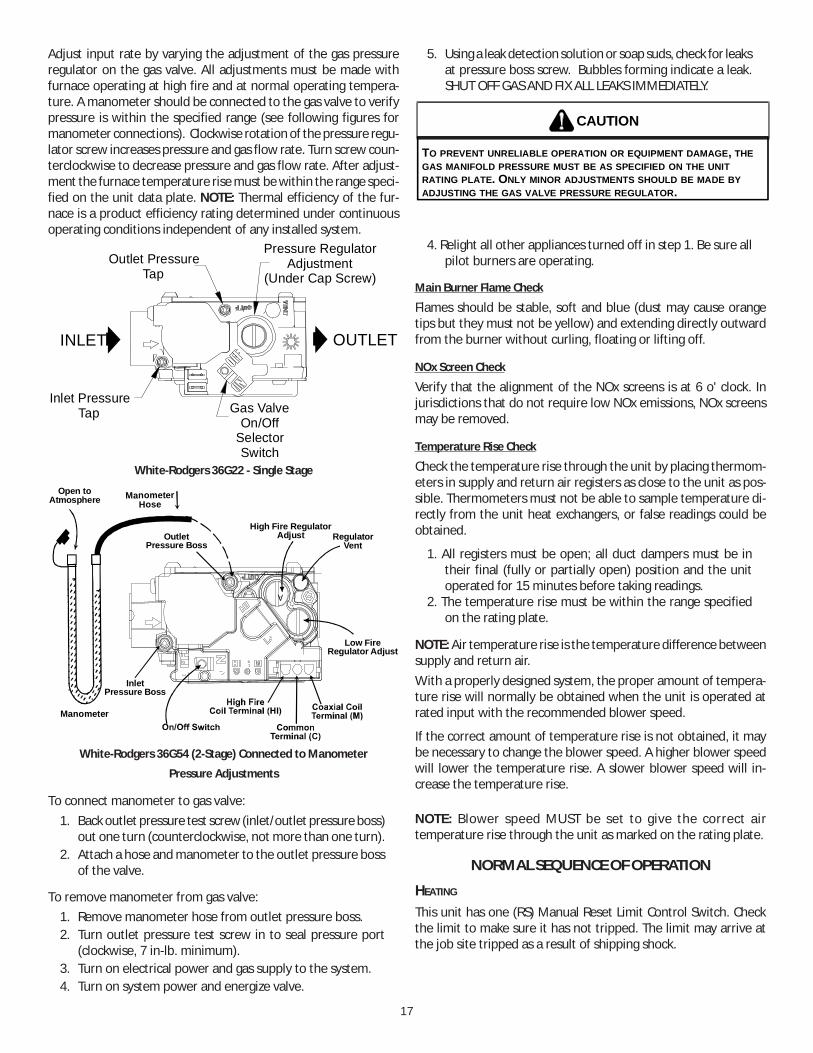
Adjust input rate by varying the adjustment of the gas pressureregulator on the gas valve. All adjustments must be made withfurnace operating at high fire and at normal operating tempera-ture. A manometer should be connected to the gas valve to verifypressure is within the specified range (see following figures formanometer connections). Clockwise rotation of the pressure regu-lator screw increases pressure and gas flow rate. Turn screw coun-terclockwise to decrease pressure and gas flow rate. After adjust-ment the furnace temperature rise must be within the range speci-fied on the unit data plate. NOTE: Thermal efficiency of the fur-nace is a product efficiency rating determined under continuousoperating conditions independent of any installed system.
Pressure RegulatorAdjustment
(Under Cap Screw)
Gas ValveOn/Off
SelectorSwitch
INLET OUTLET
Inlet PressureTap
Outlet PressureTap
White-Rodgers 36G22 - Single Stage
InletPressure Boss
Low FireRegulator Adjust
Manometer
ManometerHose
High Fire RegulatorAdjust Regulator
VentOutlet
Pressure Boss
Open toAtmosphere
White-Rodgers 36G54 (2-Stage) Connected to Manometer
Pressure Adjustments
To connect manometer to gas valve:1. Back outlet pressure test screw (inlet/outlet pressure boss)
out one turn (counterclockwise, not more than one turn).2. Attach a hose and manometer to the outlet pressure boss
of the valve.
To remove manometer from gas valve:1. Remove manometer hose from outlet pressure boss.2. Turn outlet pressure test screw in to seal pressure port
(clockwise, 7 in-lb. minimum).3. Turn on electrical power and gas supply to the system.4. Turn on system power and energize valve.
5. Using a leak detection solution or soap suds, check for leaksat pressure boss screw. Bubbles forming indicate a leak.SHUT OFF GAS AND FIX ALL LEAKS IMMEDIATELY.
TO PREVENT UNRELIABLE OPERATION OR EQUIPMENT DAMAGE, THE GAS MANIFOLD PRESSURE MUST BE AS SPECIFIED ON THE UNIT RATING PLATE. ONLY MINOR ADJUSTMENTS SHOULD BE MADE BY ADJUSTING THE GAS VALVE PRESSURE REGULATOR.
CAUTION
4. Relight all other appliances turned off in step 1. Be sure allpilot burners are operating.
Main Burner Flame Check
Flames should be stable, soft and blue (dust may cause orangetips but they must not be yellow) and extending directly outwardfrom the burner without curling, floating or lifting off.
NOx Screen Check
Verify that the alignment of the NOx screens is at 6 o' clock. Injurisdictions that do not require low NOx emissions, NOx screensmay be removed.
Temperature Rise Check
Check the temperature rise through the unit by placing thermom-eters in supply and return air registers as close to the unit as pos-sible. Thermometers must not be able to sample temperature di-rectly from the unit heat exchangers, or false readings could beobtained.
1. All registers must be open; all duct dampers must be intheir final (fully or partially open) position and the unitoperated for 15 minutes before taking readings.
2. The temperature rise must be within the range specifiedon the rating plate.
NOTE: Air temperature rise is the temperature difference betweensupply and return air.With a properly designed system, the proper amount of tempera-ture rise will normally be obtained when the unit is operated atrated input with the recommended blower speed.
If the correct amount of temperature rise is not obtained, it maybe necessary to change the blower speed. A higher blower speedwill lower the temperature rise. A slower blower speed will in-crease the temperature rise.
NOTE: Blower speed MUST be set to give the correct airtemperature rise through the unit as marked on the rating plate.
NORMAL SEQUENCE OF OPERATION
HEATING
This unit has one (RS) Manual Reset Limit Control Switch. Checkthe limit to make sure it has not tripped. The limit may arrive atthe job site tripped as a result of shipping shock.

18
If the ventermotor comes on, but the unit does not attempt igni-tion, check if the ALS (Auxiliary High Limit Control Switch) requiresresetting.
1. With electricity and gas turned on, the system switch inthe “HEAT” or “AUTO” position and the fan switch in the“AUTO” position, the thermostat will close the circuitbetween unit terminals R and W (R-W) when thetemperature falls below the thermostat setting.
2. D1 on IIC energizes relay IDMR.3. Relay IDMR energizes the ventermotor IDM.4. Operation of the ventermotor closes the pressure switch
PS located in the burner compartment. Unless excessivetemperatures or shipping shock have opened high limitcontrol ALS, power is fed to the integrated ignition control,which then initiates a 15-second pre-purge time delay.During this period, the ventermotor will clear thecombustion chamber of any residual gas.
5. After the pre-purge period, the ignition control energizesthe Wl-C gas valve and simultaneously initiates a “three(3)-try” spark ignition sequence.
6. When the burners are ignited, a minimum one (1) micro-amp DC current will flow through the flame between thesensor electrode and the grounded burner.
7. When the controller proves that the flame has beenestablished, it will keep the gas valve energized anddiscontinue the ignition spark. High stage manifoldpressure will be approximately 3.5" w.c. for natural gasand 10.0" w.c. for propane (LP). Low fire natural gas is 2.0”w.c.; low fire propane 6.0” w.c.
8. If the control is unable to ignite the burners after its initialattempt, it will initiate another purge and spark sequence.A third purge and spark sequence will be initiated if thesecond attempt is unsuccessful. If the third attempt isunsuccessful, the controller will close the gas valve andlock itself out. It may be reset by momentarily interruptingpower. This may be accomplished by briefly lowering theroom thermostat set-point below room temperature, orby shutting off the main power to the unit. (See TP-105for more details.)
9. Integrated ignition control will close its normally opencontacts after a delay of approximately 30 seconds. Thisaction energizes contactor BC and starts the supply fanmotor. Operation of the supply fan circulates air acrossthe heat exchanger and delivers heated air to theconditioned space.
10. When the space temperature rises, the thermostat willopen R-W. Opening R-W will cause the gas valve to close,and the furnace to shut down.
11. The furnace has three high temperature limit controls,which can shut down the burner. They do not shut downthe ventermotor.
Unit Shutdown
1. Set the thermostat to lowest setting.2. Turn off the electrical power supply to the unit.3. Remove the heat exchanger door on the side of the unit
by removing screws.
4. Move the gas control valve switch to the OFF position. Donot force.
5. Close manual gas shut off valve external to the unit.6. Replace the heat exchanger door on the unit.7. If cooling and/or air circulation will be desired, turn ON
the electrical power.
AUTOMATIC RESET HIGH LIMIT CONTROL (LS)Located in the burner compartment on the heat exchanger, its sens-ing element projects through the blower section bulkhead andsenses the temperature at the rear of the furnace. It will cycle thefurnace off if the temperature exceeds 100°F plus maximum rise.
AUXILIARY HIGH LIMIT CONTROL (ALS)Located in the blower compartment on the blower housing, itsenses air temperature within the blower compartment and pro-tects the filters from excessive temperature. It will shut down thefurnace if it senses excessive temperatures.
Elevated temperatures at the control are normally caused byblower failure. The reason for the opening should be determinedand repaired prior to resetting.
MANUAL RESET FLAME ROLLOUT CONTROL (RS)Located in the burner compartment at the top of the burner as-sembly, it senses high temperature that could occur if the heatexchanger tubes were plugged and the flame was rolling out in-stead of entering the tubes. It has a manual push-button reset thatcannot be actuated until the limit control has cooled.
The reason for elevated temperatures at the control should bedetermined and repaired prior to resetting this manual reset con-trol.
WARNING
TO AVOID PROPERTY DAMAGE, PERSONAL INJURY OR DEATH DUE TO FIREOR EXPLOSION, A QUALIFIED SERVICER MUST INVESTIGATE THE REASON FORTHE ROLLOUT PROTECTION DEVICE TO OPEN BEFORE MANUALLY RESETTINGTHE ROLLOUT PROTECTION DEVICE.
REFRIGERATION SYSTEM CHECKS
Ensure the hold-down bolts on the compressor are secure and havenot vibrated loose during shipment. Check that vibration grom-mets have been installed. Visually check all piping and clamps. Theentire refrigeration system has been factory charged and tested,making it unnecessary to field charge. Factory charges are shownon the unit nameplate.
START-UP PROCEDURE AND CHECKLIST
Begin with power turned off at all disconnects.
1. Turn thermostat system switch to “Cool,” and fan switchto “Auto” and turn temperature setting as high as it willgo.
2. Inspect all registers and set them to the normal openposition.
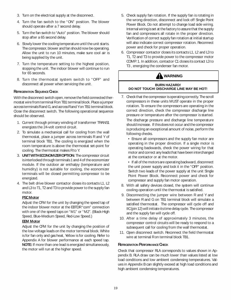
19
3. Turn on the electrical supply at the disconnect.
4. Turn the fan switch to the “ON” position. The blowershould operate after a 7 second delay.
5. Turn the fan switch to “Auto” position. The blower shouldstop after a 65 second delay.
6. Slowly lower the cooling temperature until the unit starts.The compressor, blower and fan should now be operating.Allow the unit to run 10 minutes, make sure cool air isbeing supplied by the unit.
7. Turn the temperature setting to the highest position,stopping the unit. The indoor blower will continue to runfor 65 seconds.
8. Turn the thermostat system switch to “OFF” anddisconnect all power when servicing the unit.
REFRIGERATION SEQUENCE CHECK
With the disconnect switch open, remove the field connected ther-mostat wire from terminal R on TB1 terminal block. Place a jumperacross terminals R and G, and across R and Y on TB1 terminal block.Close the disconnect switch. The following operational sequenceshould be observed.
1. Current through primary winding of transformer TRANS1energizes the 24-volt control circuit.
2. To simulate a mechanical call for cooling from the wallthermostat, place a jumper across terminals R and Y ofterminal block TB1. The cooling is energized when theroom temperature is above the thermostat set-point forcooling. The thermostat makes R to Y.
3. UNIT WITH ECONOMIZER OPTION: The compressor circuitis interlocked through terminals 1 and 4 of the economizermodule. If the outdoor air enthalpy (temperature andhumidity) is not suitable for cooling, the economizerterminals will be closed permitting compressor to beenergized.
4. The belt drive blower contactor closes its contacts L1, L2and L3 to T1, T2 and T3 to provide power to the supply fanmotor.PSC MotorAdjust the CFM for the unit by changing the speed tap ofthe indoor blower motor at the EBTDR “com” connectionwith one of the speed taps on “M1” or “M2”. (Black-HighSpeed, Blue-Medium Speed, Red-Low Speed.)EEM MotorAdjust the CFM for the unit by changing the position ofthe low voltage leads on the motor terminal block. Whiteis for fan only and gas heat, Yellow is for cooling. Refer toAppendix A for blower performance at each speed tap.NOTE: If more than one lead is energized simultaneously,the motor will run at the higher speed.
5. Check supply fan rotation. If the supply fan is rotating inthe wrong direction, disconnect and lock off Single PointPower Block. Do not attempt to change load side wiring.Internal wiring is set at the factory to assure that the supplyfan and compressors all rotate in the proper direction.Verification of correct supply fan rotation at initial startupwill also indicate correct compressor rotation. Reconnectpower and check for proper operation.
6. Compressor contactor closes its contacts L1, L2 and L3 toT1, T2 and T3 to provide power to the compressor motorCOMP. 1. In addition, contactor C1 closes its contact L3 toT3 , energizing the condenser fan motor.
BURN HAZARD!DO NOT TOUCH! DISCHARGE LINE MAY BE HOT!
WARNING
7. Check that the compressor is operating correctly. The scrollcompressors in these units MUST operate in the properrotation. To ensure the compressors are operating in thecorrect direction, check the compressor discharge linepressure or temperature after the compressor is started.The discharge pressure and discharge line temperatureshould increase. If this does not occur and the compressoris producing an exceptional amount of noise, perform thefollowing checks.
• Ensure all compressors and the supply fan motor areoperating in the proper direction. If a single motor isoperating backwards, check the power wiring for thatmotor and correct any leads that have been interchangedat the contactor or at the motor.• If all of the motors are operating backward, disconnectthe unit power supply and lock it in the “OFF” position.Switch two leads of the power supply at the unit SinglePoint Power Block. Reconnect power and check forcompressor and supply fan motor operation.
8. With all safety devices closed, the system will continuecooling operation until the thermostat is satisfied.
9. Disconnecting the jumper wire between R and Y andbetween R and G on TB1 terminal block will simulate asatisfied thermostat. The compressor will cycle off andIIC (pin 12) will initiate its time delay cycle. The compressorand the supply fan will cycle off.
10. After a time delay of approximately 3 minutes, thecompressor control circuits will be ready to respond to asubsequent call for cooling from the wall thermostat.
11. Open disconnect switch. Reconnect the field thermostatwire at terminal R on terminal block TB1.
REFRIGERATION PERFORMANCE CHECK
Check that compressor RLA corresponds to values shown in Ap-pendix B. RLA draw can be much lower than values listed at lowload conditions and low ambient condensing temperatures. Val-ues in Appendix B can slightly exceed at high load conditions andhigh ambient condensing temperatures.
20
FINAL SYSTEM CHECKS
1. Check to see if all supply and return air grilles are adjustedand the air distribution system is balanced for the bestcompromise between heating and cooling.
2. Check for air leaks in the ductwork. See Sections on AirFlow Adjustments.
3. Make sure the unit is free of “rattles”, and the tubing inthe unit is free from excessive vibration. Also make suretubes or lines are not rubbing against each other or sheetmetal surfaces or edges. If so, correct the trouble.
4. Set the thermostat at the appropriate setting for coolingand heating or automatic changeover for normal use.
5. Be sure the Owner is instructed on the unit operation, filter,servicing, correct thermostat operation, etc.
MAINTENANCE
HIGH VOLTAGE! DISCONNECT ALL POWER BEFORE SERVICING OR INSTALLING THIS UNIT. MULTIPLE POWER SOURCES MAY BE PRESENT. FAILURE TO DO SO MAY CAUSE PROPERTY DAMAGE, PERSONAL INJURY OR DEATH.
WARNING
TO PREVENT PERSONAL INJURY OR DEATH DUE TO IMPROPER INSTALLATION, ADJUSTMENT, ALTERATION, SERVICE OR MAINTENANCE, REFER TO THIS MANUAL. FOR ADDITIONAL ASSISTANCE OR INFORMATION, CONSULT A QUALIFIED INSTALLER, SERVICE AGENCY OR THE GAS SUPPLIER.
WARNING
SHEET METAL PARTS, SCREWS, CLIPS AND SIMILAR ITEMS INHERENTLY HAVE SHARP EDGES, AND IT IS NECESSARY THAT THE INSTALLER AND SERVICE PERSONNEL EXERCISE CAUTION.
CAUTION
Preventive maintenance is the best way to avoid unnecessary ex-pense and inconvenience. Have this system inspected at regularintervals by qualified service personnel, at least twice a year. Rou-tine maintenance should cover the following items:
1. Tighten all belts, set screws, and wire connections.2. Clean evaporator and condenser coils mechanically or with
cold water, if necessary. Usually any fouling is only mattedon the entering air face of the coil and can be removed bybrushing.
3. Lubricate motor bearings.4. Align or replace belts as needed.5. Replace filters as needed (see below).6. Check for blockage of condensate drain.7. Check power and control voltages.8. Check running amperage.9. Check operating temperatures and pressures.
10. Check and adjust temperature and pressure controls.11. Check and adjust damper linkages.12. Check operation of all safety controls.13. Examine gas furnaces (see below and the User’s
Information Manual).14. Check condenser fans and tighten set screws.
FILTERS
CAUTION
TO PREVENT PROPERTY DAMAGE DUE TO FIRE AND LOSS OFEQUIPMENT EFFICIENCY OR EQUIPMENT DAMAGE DUE TO DUST AND LINTBUILD UP ON INTERNAL PARTS, NEVER OPERATE UNIT WITHOUT AN AIRFILTER INSTALLED IN THE RETURN AIR SYSTEM.
Every application may require a different frequency of replace-ment of dirty filters. Filters must be replaced at least every three(3) months during operating seasons.
Dirty filters are the most common cause of inadequate heating orcooling performance. Filter inspection should be made at leastevery two months; more often if necessary because of local condi-tions and usage.
Dirty throwaway filters should be discarded and replaced with anew, clean filter.
Disposable return air filters are supplied with this unit. See theunit Specification Sheet or Technical Manual for the correct sizeand part number. To remove the filters, remove the filter accesspanel on return side of the unit.
CABINET FINISH MAINTENANCE
Use a fine grade automotive wax on the cabinet finish to maintainthe finish’s original high luster. This is especially important in in-stallations with extended periods of direct sunlight.
CLEAN OUTSIDE COIL (QUALIFIED SERVICER ONLY)The coil with the outside air flowing over it should be inspectedannually and cleaned as frequently as necessary to keep the finnedareas free of lint, hair and debris.
CONDENSER AND INDUCED DRAFT MOTORS
Bearings on the condenser fan motors and the combustion fanmotor are permanently lubricated. No additional oiling is required.
FLAME SENSOR (QUALIFIED SERVICER ONLY)A drop in the flame current can be caused by a nearly invisiblecoating on the flame sensor. This coating, created by the fuel orcombustion air supply, can be removed by carefully cleaning theflame sensor with steel wool.
NOTE: After cleaning, the microamp signal should be stable and inthe range of 4 - 6 microamps DC.
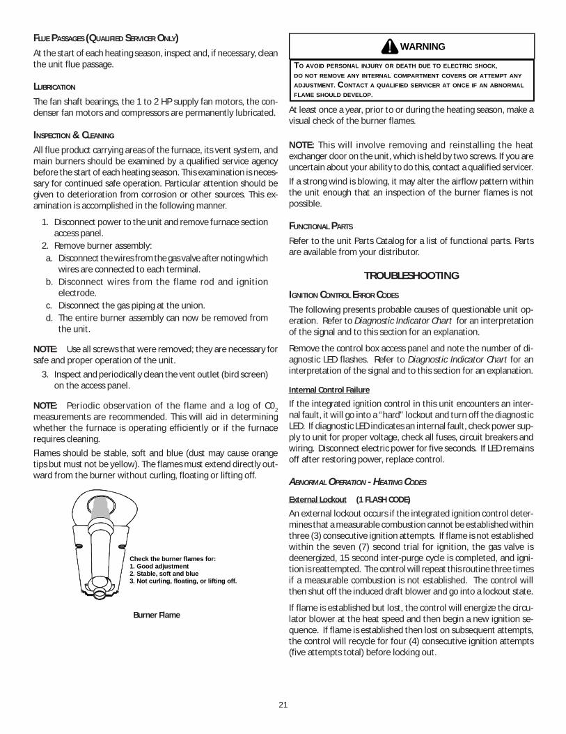
21
FLUE PASSAGES (QUALIFIED SERVICER ONLY)At the start of each heating season, inspect and, if necessary, cleanthe unit flue passage.
LUBRICATION
The fan shaft bearings, the 1 to 2 HP supply fan motors, the con-denser fan motors and compressors are permanently lubricated.
INSPECTION & CLEANING
All flue product carrying areas of the furnace, its vent system, andmain burners should be examined by a qualified service agencybefore the start of each heating season. This examination is neces-sary for continued safe operation. Particular attention should begiven to deterioration from corrosion or other sources. This ex-amination is accomplished in the following manner.
1. Disconnect power to the unit and remove furnace sectionaccess panel.
2. Remove burner assembly:a. Disconnect the wires from the gas valve after noting which
wires are connected to each terminal.b. Disconnect wires from the flame rod and ignition
electrode.c. Disconnect the gas piping at the union.d. The entire burner assembly can now be removed from
the unit.
NOTE: Use all screws that were removed; they are necessary forsafe and proper operation of the unit.
3. Inspect and periodically clean the vent outlet (bird screen)on the access panel.
NOTE: Periodic observation of the flame and a log of C02measurements are recommended. This will aid in determiningwhether the furnace is operating efficiently or if the furnacerequires cleaning.Flames should be stable, soft and blue (dust may cause orangetips but must not be yellow). The flames must extend directly out-ward from the burner without curling, floating or lifting off.
Check the burner flames for: 1. Good adjustment2. Stable, soft and blue 3. Not curling, floating, or lifting off.
Burner Flame
WARNING
TO AVOID PERSONAL INJURY OR DEATH DUE TO ELECTRIC SHOCK,DO NOT REMOVE ANY INTERNAL COMPARTMENT COVERS OR ATTEMPT ANYADJUSTMENT. CONTACT A QUALIFIED SERVICER AT ONCE IF AN ABNORMALFLAME SHOULD DEVELOP.
At least once a year, prior to or during the heating season, make avisual check of the burner flames.
NOTE: This will involve removing and reinstalling the heatexchanger door on the unit, which is held by two screws. If you areuncertain about your ability to do this, contact a qualified servicer.If a strong wind is blowing, it may alter the airflow pattern withinthe unit enough that an inspection of the burner flames is notpossible.
FUNCTIONAL PARTS
Refer to the unit Parts Catalog for a list of functional parts. Partsare available from your distributor.
TROUBLESHOOTING
IGNITION CONTROL ERROR CODES
The following presents probable causes of questionable unit op-eration. Refer to Diagnostic Indicator Chart for an interpretationof the signal and to this section for an explanation.
Remove the control box access panel and note the number of di-agnostic LED flashes. Refer to Diagnostic Indicator Chart for aninterpretation of the signal and to this section for an explanation.
Internal Control Failure
If the integrated ignition control in this unit encounters an inter-nal fault, it will go into a “hard” lockout and turn off the diagnosticLED. If diagnostic LED indicates an internal fault, check power sup-ply to unit for proper voltage, check all fuses, circuit breakers andwiring. Disconnect electric power for five seconds. If LED remainsoff after restoring power, replace control.
ABNORMAL OPERATION - HEATING CODES
External Lockout (1 FLASH CODE)
An external lockout occurs if the integrated ignition control deter-mines that a measurable combustion cannot be established withinthree (3) consecutive ignition attempts. If flame is not establishedwithin the seven (7) second trial for ignition, the gas valve isdeenergized, 15 second inter-purge cycle is completed, and igni-tion is reattempted. The control will repeat this routine three timesif a measurable combustion is not established. The control willthen shut off the induced draft blower and go into a lockout state.
If flame is established but lost, the control will energize the circu-lator blower at the heat speed and then begin a new ignition se-quence. If flame is established then lost on subsequent attempts,the control will recycle for four (4) consecutive ignition attempts(five attempts total) before locking out.
22
The diagnostic fault code is 1 flash for a lockout due to failed igni-tion attempts or flame dropouts. The integrated control will auto-matically reset after one hour, or it can be reset by removing thethermostat signal or disconnecting the electrical power supply forover five seconds. If the diagnostic LED indicates an external lock-out, perform the following checks:
• Check the supply and manifold pressures• Check the gas orifices for debris• Check gas valve for proper operation• Check secondary limit
A dirty filter, excessive duct static, insufficient air flow,a faulty limit, or a failed circulator blower can causethis limit to open. Check filters, total external ductstatic, circulator blower motor, blower motor speed tap(see wiring diagram), and limit. An interruption inelectrical power during a heating cycle may also causethe auxiliary limit to open. The automatic resetsecondary limit is located on top of the circulatorblower assembly.
• Check rollout limitIf the burner flames are not properly drawn into theheat exchanger, the flame rollout protection device willopen. Possible causes are restricted or blocked fluepassages, blocked or cracked heat exchanger, a failedinduced draft blower, or insufficient combustion air.The rollout protection device is a manual reset limitlocated on the burner bracket. The cause of the flamerollout must be determined and corrected beforeresetting the limit.
• Check flame sensorA drop in flame signal can be caused by nearly invisiblecoating on the sensor. Remove the sensor and carefullyclean with steel wool.
• Check wiringCheck wiring for opens/shorts and miswiring.
IMPORTANT: If you have to frequently reset your gas/electricpackage unit, it means that a problem exists that should becorrected. Contact a qualified servicer for further information.
Pressure Switch Stuck Open (2 FLASH CODE)
IA pressure switch stuck open can be caused by a faulty pressureswitch, faulty wiring, a disconnected or damaged hose, a blockedor restricted flue, or a faulty induced draft blower. If the controlsenses an open pressure switch during the pre-purge cycle, theinduced draft blower only will be energized.
If the pressure switch opens after ignition has begun the gas valveis deenergized, the circulator blower heat off cycle begins, and theinduced draft blower remains on. The diagnostic fault code is twoflashes.
Pressure Switch Stuck Closed (3 FLASH CODE)
A stuck closed pressure switch can be caused by a faulty pressureswitch or faulty wiring. If the control encounters a pressure switchstuck closed, the induced draft blower remains off. The diagnosticLED code for this fault is three (3) flashes.
Open Thermal Protection Device (4 FLASH CODE)
If the primary limit switch opens, the gas valve is immediatelydeenergized, the induced draft and air circulating blowers are en-ergized. The induced draft and air circulator blowers remain en-ergized until the limit switch recloses. The diagnostic fault codefor an open limit is four (4) flashes.
A primary limit will open due to excessive supply air temperatures.This can be caused by a dirty filter, excessive duct static, insuffi-cient air flow, or a faulty limit. Check filters, total external ductstatic, blower motor, blower motor speed tap (see wiring diagram),and limit. This limit will automatically reset once the temperaturefalls below a preset level.
Flame Detected with Gas Valve Closed (5 FLASH CODE)
If flame is detected with the gas valve deenergized, the combus-tion and air circulator blowers are energized. The diagnostic faultcode is five (5) flashes for this condition. The control can be resetby removing the power supply to the unit or it will automaticallyreset after one hour. Miswiring is the probable cause for this fault.
ABNORMAL OPERATION - COOLING CODES
Short Cycle Compressor Delay (6 FLASH CODE)
The automatic ignition control has a built-in feature that preventsdamage to the compressor in short cycling situations. In the eventof intermittent power losses or intermittent thermostat operation,the ignition control will delay output to the compressor contactorfor three minutes from the time power is restored. (Compressoris off a total of three minutes). The diagnostic LED will flash six (6)times to indicate the compressor contactor output is being de-layed.
NOTE: Some electronic thermostats also have a built-in compressorshort cycle timer that may be longer than the three minute delaygiven above. If you are using an electronic thermostat and thecompressor has not started after three minutes, wait an additionalfive minutes to allow the thermostat to complete its short cycledelay time.
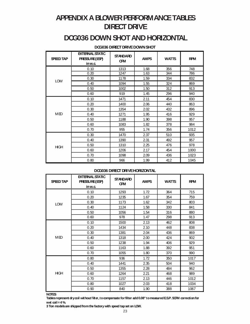
23
APPENDIX A BLOWER PERFORMANCE TABLESDIRECT DRIVE
DCG036 DOWN SHOT AND HORIZONTAL
SPEED TAP EXTERNAL STATIC PRESSURE (ESP)
in w.c.
STANDARDCFM AMPS WATTS RPM
0.10 1313 1.68 356 7480.20 1247 1.63 344 7860.30 1178 1.59 334 8320.40 1094 1.55 324 8690.50 1002 1.50 312 9130.60 919 1.45 296 9400.10 1471 2.11 454 8300.20 1400 2.06 440 8630.30 1354 2.02 432 8960.40 1271 1.95 416 9290.50 1188 1.90 398 9570.60 1083 1.82 378 9840.70 955 1.74 356 10120.30 1470 2.37 510 9350.40 1390 2.31 492 9570.50 1310 2.25 476 9780.60 1206 2.17 454 10000.70 1098 2.09 436 10230.80 966 1.99 412 1045
SPEED TAP EXTERNAL STATIC PRESSURE (ESP)
in w.c.
STANDARDCFM AMPS WATTS RPM
0.10 1293 1.72 364 7150.20 1235 1.67 354 7590.30 1173 1.62 342 8030.40 1124 1.58 330 8410.50 1056 1.54 316 8800.60 978 1.47 298 9130.10 1500 2.13 462 8080.20 1434 2.10 448 8380.30 1381 2.04 436 8690.40 1318 2.00 424 9020.50 1238 1.94 406 9290.60 1163 1.88 392 9510.70 1055 1.80 370 9900.80 936 1.72 350 10170.40 1441 2.35 504 9400.50 1355 2.28 484 9620.60 1264 2.21 468 9890.70 1157 2.13 446 10120.80 1027 2.03 418 10340.90 840 1.90 388 1067
NOTES:
3 Ton models are shipped from the factory with speed tap set on LOW.
Tables represent dry coil without f ilter, to compensate for filter add 0.08" to measured E.S.P. SCFM correction for wet coil = 4 %.
DCG036 DIRECT DRIVE HORIZONTAL
LOW
MED
HIGH
HIGH
DCG036 DIRECT DRIVE DOWN SHOT
LOW
MED

24
APPENDIX A BLOWER PERFORMANCE TABLESDIRECT DRIVE
DCG048 DOWN SHOT AND HORIZONTAL
SPEED TAP EXTERNAL STATIC
PRESSURE (ESP)in w.c.
STANDARDCFM
AMPS WATTS RPM
0.10 1592 2.54 543 8150.20 1528 2.43 521 8580.30 1464 2.32 499 9010.40 1380 2.21 475 9300.50 1296 2.10 451 9590.10 1828 3.08 665 8920.20 1700 2.75 601 9240.30 1606 2.61 563 9660.40 1531 2.48 537 9900.50 1401 2.32 503 10230.60 1287 2.22 477 10450.70 1123 2.05 441 10730.10 1926 3.34 740 9370.20 1825 3.18 700 9650.30 1712 3.03 660 9890.40 1598 2.87 626 10150.50 1482 2.76 596 10320.60 1357 2.62 564 1049
SPEED TAP EXTERNAL STATIC
PRESSURE (ESP)in w.c.
STANDARDCFM
AMPS WATTS RPM
0.10 1612 2.60 554 7890.20 1548 2.49 532 8320.30 1484 2.38 510 8750.40 1400 2.27 486 9040.50 1316 2.16 462 9330.10 1846 3.14 676 8660.20 1718 2.81 612 8980.30 1624 2.67 574 9400.40 1549 2.54 548 9640.50 1419 2.38 514 9970.60 1305 2.28 488 10190.70 1141 2.11 452 10470.10 1954 3.43 758 9240.20 1853 3.27 718 9520.30 1740 3.12 678 9760.40 1626 2.96 644 10020.50 1510 2.85 614 10190.60 1385 2.71 582 1036
NOTES:
4 Ton models are shipped from the factory with speed tap set on MED.
HIGH
DCG048 DIRECT DRIVE DOWN SHOT
LOW
MED
Tables represent dry coil without filter, to compensate for filter add 0.08" to measured E.S.P. SCFM correction for wet coil = 4 %.
DCG048 DIRECT DRIVE HORIZONTAL
LOW
MED
HIGH
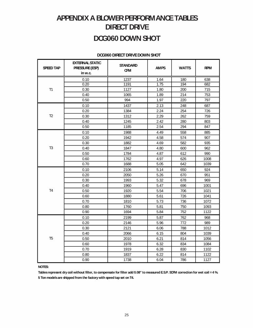
25
APPENDIX A BLOWER PERFORMANCE TABLESDIRECT DRIVE
DCG060 DOWN SHOT
SPEED TAP EXTERNAL STATIC
PRESSURE (ESP)in w.c.
STANDARDCFM
AMPS WATTS RPM
0.10 1237 1.64 180 6380.20 1191 1.75 194 6820.30 1127 1.80 200 7150.40 1065 1.89 214 7530.50 994 1.97 220 7970.10 1437 2.13 248 6870.20 1384 2.24 254 7260.30 1312 2.29 262 7590.40 1245 2.42 280 8030.50 1185 2.54 294 8470.10 1988 4.49 558 8850.20 1942 4.58 574 9070.30 1882 4.69 582 9350.40 1847 4.80 600 9620.50 1784 4.87 612 9900.60 1762 4.97 626 10080.70 1688 5.05 642 10390.10 2106 5.14 650 9240.20 2050 5.26 670 9510.30 1993 5.32 678 9690.40 1960 5.47 696 10010.50 1920 5.54 706 10210.60 1880 5.61 726 10410.70 1810 5.73 736 10720.80 1760 5.81 750 10930.90 1694 5.84 752 11220.10 2199 5.87 762 9680.20 2146 5.96 772 9890.30 2121 6.06 788 10120.40 2066 6.15 804 10390.50 2010 6.21 814 10560.60 1978 6.32 834 10840.70 1919 6.28 830 11020.80 1837 6.22 814 11220.90 1738 6.04 786 1127
NOTES:
5 Ton models are shipped from the factory with speed tap set on T4.
T5
DCG060 DIRECT DRIVE DOWN SHOT
Tables represent dry coil without filter, to compensate for filter add 0.08" to measured E.S.P. SCFM correction for wet coil = 4 %.
T1
T2
T3
T4

26
APPENDIX A BLOWER PERFORMANCE TABLESDIRECT DRIVE
DCG060 HORIZONTAL
SPEED TAP EXTERNAL STATIC
PRESSURE (ESP)in w.c.
STANDARDCFM
AMPS WATTS RPM
0.10 1416 1.63 176 5880.20 1295 1.61 174 6210.30 1200 1.68 186 6600.40 1133 1.79 196 7040.50 1045 1.90 208 7530.10 1543 2.00 220 6270.20 1485 2.12 236 6710.30 1425 2.20 250 6980.40 1352 2.26 258 7480.50 1304 2.39 274 7860.10 2107 4.02 502 7970.20 2031 4.13 518 8190.30 1980 4.27 536 8580.40 1954 4.37 554 8800.50 1887 4.48 572 9130.60 1839 4.58 582 9400.70 1782 4.72 602 9680.10 2224 4.73 592 8320.20 2165 4.79 612 8600.30 2123 4.91 630 8910.40 2079 5.01 642 9130.50 2029 5.14 666 9460.60 1978 5.26 676 9690.70 1926 5.38 698 10010.80 1872 5.48 712 10280.90 1817 5.58 722 10560.10 2318 5.42 700 8740.20 2296 5.55 720 9030.30 2228 5.66 734 9290.40 2193 5.76 748 9500.50 2145 5.90 766 9790.60 2097 5.99 784 10120.70 2054 6.10 798 10340.80 1991 6.15 810 10500.90 1952 6.26 826 1079
NOTES:
5 Ton models are shipped from the factory with speed tap set on T4.
T5
DCG060 DIRECT DRIVE HORIZONTAL
Tables represent dry coil without filter, to compensate for filter add 0.08" to measured E.S.P.SCFM correction for wet coil = 4 %.
T1
T2
T3
T4
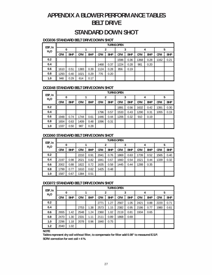
27
APPENDIX A BLOWER PERFORMANCE TABLESBELT DRIVE
STANDARD DOWN SHOTDCG036 STANDARD BELT DRIVE DOWN SHOT
CFM BHP CFM BHP CFM BHP CFM BHP CFM BHP CFM BHP
0.2 1596 0.36 1368 0.28 1162 0.210.4 1468 0.37 1224 0.28 981 0.200.6 1610 0.51 1383 0.39 1124 0.28 856 0.190.8 1293 0.40 1021 0.29 776 0.201.0 948 0.29 614 0.17
DCG048 STANDARD BELT DRIVE DOWN SHOT
CFM BHP CFM BHP CFM BHP CFM BHP CFM BHP CFM BHP
0.2 1891 0.56 1632 0.42 1391 0.300.4 1796 0.57 1533 0.43 1290 0.31 1055 0.190.6 1948 0.74 1744 0.61 1446 0.44 1206 0.32 910 0.190.8 1654 0.63 1409 0.48 1096 0.311.0 1337 0.50 987 0.28
DCG060 STANDARD BELT DRIVE DOWN SHOT
CFM BHP CFM BHP CFM BHP CFM BHP CFM BHP CFM BHP
0.2 2210 0.91 2041 0.76 1869 0.63 1739 0.52 1565 0.400.4 2197 0.98 2021 0.82 1841 0.67 1660 0.54 1521 0.44 1339 0.320.6 2002 0.88 1822 0.72 1635 0.58 1445 0.44 1288 0.350.8 1799 0.77 1610 0.62 1425 0.481.0 1587 0.67 1384 0.51
DCG072 STANDARD BELT DRIVE DOWN SHOT
CFM BHP CFM BHP CFM BHP CFM BHP CFM BHP CFM BHP
0.2 2771 1.27 2567 1.05 2421 0.88 2220 0.710.4 2753 1.38 2573 1.15 2382 0.95 2186 0.77 1980 0.610.6 2655 1.42 2548 1.24 2360 1.02 2119 0.81 1934 0.650.8 2470 1.30 2331 1.11 2111 0.89 1868 0.691.0 2296 1.18 2078 0.96 1840 0.751.2 2040 1.02
NOTE
TURNS OPENESP, In
H2O 4 50 1 2 3
ESP, In H2O
TURNS OPEN0 1 2 3 4 5
Tables represent dry coil without filter, to compensate for filter add 0.08" to measured E.S.P.SCFM correction for wet coil = 4 %.
ESP, In H2O
TURNS OPEN0 1 2 3 4 5
ESP, In H2O
TURNS OPEN0 1 2 3 4 5
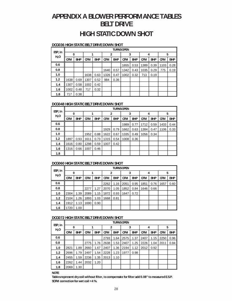
28
APPENDIX A BLOWER PERFORMANCE TABLESBELT DRIVE
HIGH STATIC DOWN SHOTDCG036 HIGH STATIC BELT DRIVE DOWN SHOT
CFM BHP CFM BHP CFM BHP CFM BHP CFM BHP CFM BHP
0.6 1655 0.53 1389 0.39 1103 0.280.8 1640 0.57 1342 0.43 1035 0.29 775 0.191.0 1638 0.63 1326 0.47 1002 0.32 713 0.191.2 1638 0.69 1307 0.52 984 0.361.4 1307 0.58 1002 0.421.6 1002 0.48 717 0.321.8 717 0.38
DCG048 HIGH STATIC BELT DRIVE DOWN SHOT
CFM BHP CFM BHP CFM BHP CFM BHP CFM BHP CFM BHP
0.6 1989 0.77 1712 0.59 1433 0.440.8 1929 0.79 1662 0.63 1384 0.47 1106 0.331.0 1952 0.88 1622 0.67 1335 0.49 1056 0.341.2 1897 0.93 1611 0.73 1315 0.54 1008 0.361.4 1616 0.80 1298 0.59 1007 0.421.6 1316 0.66 1007 0.461.8
DCG060 HIGH STATIC BELT DRIVE DOWN SHOT
CFM BHP CFM BHP CFM BHP CFM BHP CFM BHP CFM BHP
0.6 2262 1.16 2051 0.95 1851 0.76 1657 0.600.8 2277 1.27 2070 1.05 1852 0.84 1646 0.661.0 2304 1.39 2089 1.15 1872 0.93 1647 0.721.2 2104 1.26 1893 1.03 1668 0.811.4 1912 1.13 1690 0.901.6 1720 1.00
DCG072 HIGH STATIC BELT DRIVE DOWN SHOT
CFM BHP CFM BHP CFM BHP CFM BHP CFM BHP CFM BHP
0.6 2793 1.64 2575 1.37 2407 1.15 2250 0.960.8 2775 1.76 2638 1.53 2407 1.25 2226 1.04 2011 0.841.0 2821 1.89 2660 1.67 2407 1.36 2194 1.12 2012 0.921.2 2696 1.79 2497 1.54 2228 1.23 1977 0.981.4 2455 1.59 2236 1.35 2013 1.101.6 2262 1.44 2032 1.201.8 2069 1.30
NOTE
ESP, In H2O
TURNS OPEN0 1 2 3 4 5
ESP, In H2O
TURNS OPEN0 1 2 3 4 5
ESP, In H2O
TURNS OPEN0 1 2 3 4 5
ESP, In H2O
TURNS OPEN0 1 2 3 4 5
Tables represent dry coil without filter, to compensate for filter add 0.08" to measured E.S.P.SCFM correction for wet coil = 4 %.
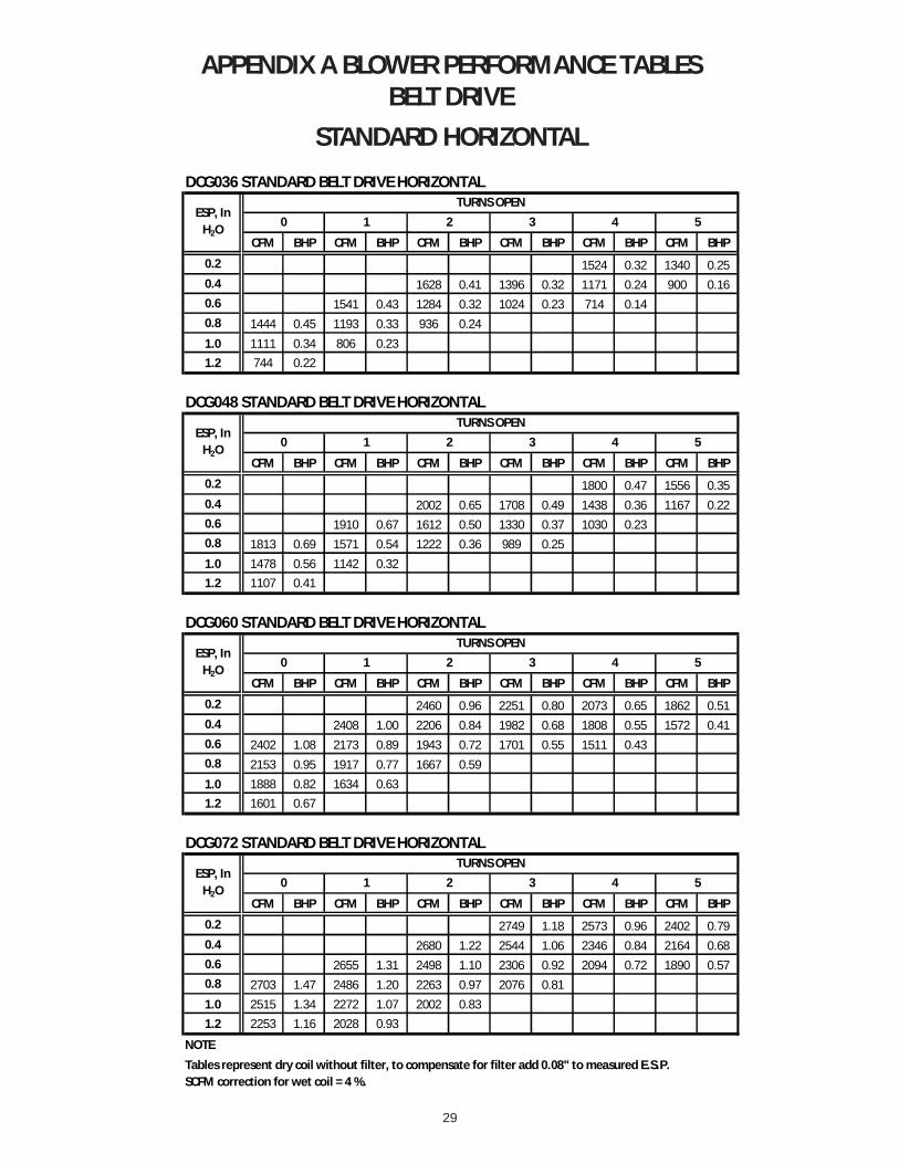
29
APPENDIX A BLOWER PERFORMANCE TABLESBELT DRIVE
STANDARD HORIZONTALDCG036 STANDARD BELT DRIVE HORIZONTAL
CFM BHP CFM BHP CFM BHP CFM BHP CFM BHP CFM BHP
0.2 1524 0.32 1340 0.250.4 1628 0.41 1396 0.32 1171 0.24 900 0.160.6 1541 0.43 1284 0.32 1024 0.23 714 0.140.8 1444 0.45 1193 0.33 936 0.241.0 1111 0.34 806 0.231.2 744 0.22
DCG048 STANDARD BELT DRIVE HORIZONTAL
CFM BHP CFM BHP CFM BHP CFM BHP CFM BHP CFM BHP
0.2 1800 0.47 1556 0.350.4 2002 0.65 1708 0.49 1438 0.36 1167 0.220.6 1910 0.67 1612 0.50 1330 0.37 1030 0.230.8 1813 0.69 1571 0.54 1222 0.36 989 0.251.0 1478 0.56 1142 0.321.2 1107 0.41
DCG060 STANDARD BELT DRIVE HORIZONTAL
CFM BHP CFM BHP CFM BHP CFM BHP CFM BHP CFM BHP
0.2 2460 0.96 2251 0.80 2073 0.65 1862 0.510.4 2408 1.00 2206 0.84 1982 0.68 1808 0.55 1572 0.410.6 2402 1.08 2173 0.89 1943 0.72 1701 0.55 1511 0.430.8 2153 0.95 1917 0.77 1667 0.591.0 1888 0.82 1634 0.631.2 1601 0.67
DCG072 STANDARD BELT DRIVE HORIZONTAL
CFM BHP CFM BHP CFM BHP CFM BHP CFM BHP CFM BHP
0.2 2749 1.18 2573 0.96 2402 0.790.4 2680 1.22 2544 1.06 2346 0.84 2164 0.680.6 2655 1.31 2498 1.10 2306 0.92 2094 0.72 1890 0.570.8 2703 1.47 2486 1.20 2263 0.97 2076 0.811.0 2515 1.34 2272 1.07 2002 0.831.2 2253 1.16 2028 0.93
NOTE
ESP, In H2O
TURNS OPEN0 1 2 3 4 5
ESP, In H2O
TURNS OPEN0 1 2 3 4 5
ESP, In H2O
TURNS OPEN0 1 2 3 4 5
Tables represent dry coil without filter, to compensate for filter add 0.08" to measured E.S.P.SCFM correction for wet coil = 4 %.
ESP, In H2O
TURNS OPEN0 1 2 3 4 5
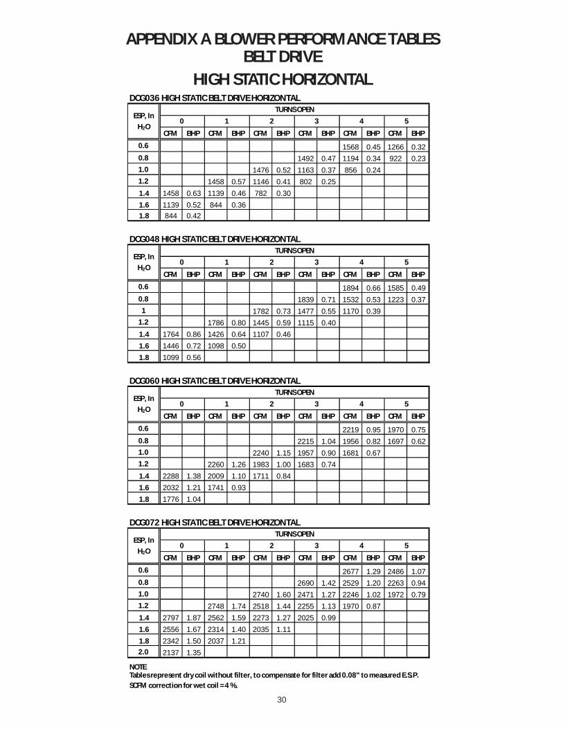
30
APPENDIX A BLOWER PERFORMANCE TABLESBELT DRIVE
HIGH STATIC HORIZONTALDCG036 HIGH STATIC BELT DRIVE HORIZONTAL
CFM BHP CFM BHP CFM BHP CFM BHP CFM BHP CFM BHP
0.6 1568 0.45 1266 0.320.8 1492 0.47 1194 0.34 922 0.231.0 1476 0.52 1163 0.37 856 0.241.2 1458 0.57 1146 0.41 802 0.251.4 1458 0.63 1139 0.46 782 0.301.6 1139 0.52 844 0.361.8 844 0.42
DCG048 HIGH STATIC BELT DRIVE HORIZONTAL
CFM BHP CFM BHP CFM BHP CFM BHP CFM BHP CFM BHP
0.6 1894 0.66 1585 0.490.8 1839 0.71 1532 0.53 1223 0.371 1782 0.73 1477 0.55 1170 0.39
1.2 1786 0.80 1445 0.59 1115 0.401.4 1764 0.86 1426 0.64 1107 0.461.6 1446 0.72 1098 0.501.8 1099 0.56
DCG060 HIGH STATIC BELT DRIVE HORIZONTAL
CFM BHP CFM BHP CFM BHP CFM BHP CFM BHP CFM BHP
0.6 2219 0.95 1970 0.750.8 2215 1.04 1956 0.82 1697 0.621.0 2240 1.15 1957 0.90 1681 0.671.2 2260 1.26 1983 1.00 1683 0.741.4 2288 1.38 2009 1.10 1711 0.841.6 2032 1.21 1741 0.931.8 1776 1.04
DCG072 HIGH STATIC BELT DRIVE HORIZONTAL
CFM BHP CFM BHP CFM BHP CFM BHP CFM BHP CFM BHP
0.6 2677 1.29 2486 1.070.8 2690 1.42 2529 1.20 2263 0.941.0 2740 1.60 2471 1.27 2246 1.02 1972 0.791.2 2748 1.74 2518 1.44 2255 1.13 1970 0.871.4 2797 1.87 2562 1.59 2273 1.27 2025 0.991.6 2556 1.67 2314 1.40 2035 1.111.8 2342 1.50 2037 1.212.0 2137 1.35
NOTE
ESP, In H2O
TURNS OPEN0 1 2 3 4 5
ESP, In H2O
TURNS OPEN0 1 2 3 4 5
ESP, In H2O
TURNS OPEN0 1 2 3 4 5
ESP, In H2O
TURNS OPEN0 1 2 3 4 5
Tables represent dry coil without filter, to compensate for filter add 0.08" to measured E.S.P.SCFM correction for wet coil = 4 %.
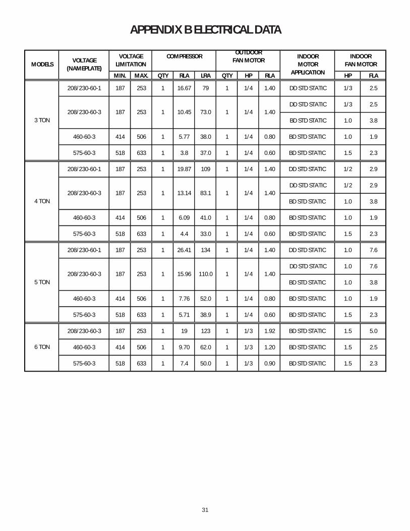
31
APPENDIX B ELECTRICAL DATA
MIN. MAX. QTY RLA LRA QTY HP RLA HP FLA
208/230-60-1 187 253 1 16.67 79 1 1/4 1.40 DD STD STATIC 1/3 2.5
DD STD STATIC 1/3 2.5
BD STD STATIC 1.0 3.8
460-60-3 414 506 1 5.77 38.0 1 1/4 0.80 BD STD STATIC 1.0 1.9
575-60-3 518 633 1 3.8 37.0 1 1/4 0.60 BD STD STATIC 1.5 2.3
208/230-60-1 187 253 1 19.87 109 1 1/4 1.40 DD STD STATIC 1/2 2.9
DD STD STATIC 1/2 2.9
BD STD STATIC 1.0 3.8
460-60-3 414 506 1 6.09 41.0 1 1/4 0.80 BD STD STATIC 1.0 1.9
575-60-3 518 633 1 4.4 33.0 1 1/4 0.60 BD STD STATIC 1.5 2.3
208/230-60-1 187 253 1 26.41 134 1 1/4 1.40 DD STD STATIC 1.0 7.6
DD STD STATIC 1.0 7.6
BD STD STATIC 1.0 3.8
460-60-3 414 506 1 7.76 52.0 1 1/4 0.80 BD STD STATIC 1.0 1.9
575-60-3 518 633 1 5.71 38.9 1 1/4 0.60 BD STD STATIC 1.5 2.3
208/230-60-3 187 253 1 19 123 1 1/3 1.92 BD STD STATIC 1.5 5.0
460-60-3 414 506 1 9.70 62.0 1 1/3 1.20 BD STD STATIC 1.5 2.5
575-60-3 518 633 1 7.4 50.0 1 1/3 0.90 BD STD STATIC 1.5 2.3
187 253 1/4 1.401 15.96 110.0 1
4 TON208/230-60-3 187 253 1 13.14 83.1
1/4 1.40
VOLTAGELIMITATION
COMPRESSOROUTDOOR
FAN MOTOR
1 10.45 73.0 1187 253
INDOORFAN MOTOR
1 1/4 1.40
INDOORMOTOR
APPLICATION
6 TON
MODELSVOLTAGE
(NAMEPLATE)
3 TON208/230-60-3
5 TON208/230-60-3
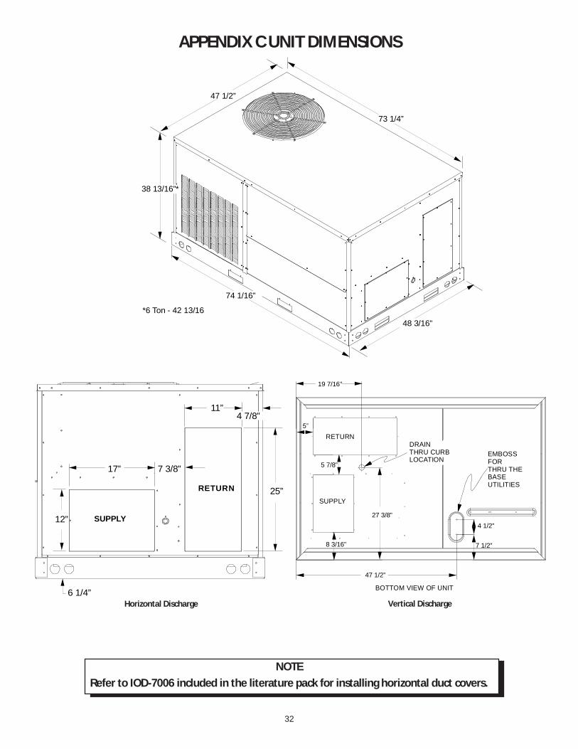
32
APPENDIX C UNIT DIMENSIONS
Horizontal Discharge Vertical Discharge
RETURN
SUPPLY12”
17” 7 3/8”
11”
25”
6 1/4”
4 7/8”
DRAINTHRU CURBLOCATION
EMBOSS FORTHRU THE BASE UTILITIES
BOTTOM VIEW OF UNIT
8 3/16”
5 7/8”
19 7/16”
27 3/8”
47 1/2”
4 1/2”
7 1/2”
SUPPLY
RETURN
73 1/4”
47 1/2”
74 1/16”
48 3/16”
38 13/16”*
*6 Ton - 42 13/16
NOTERefer to IOD-7006 included in the literature pack for installing horizontal duct covers.

33
APPENDIX D WIRING DIAGRAMSDCG0360901D/DCG048(090/115)1D* SINGLE PHASE 208/230V/60HZ DIRECT DRIVE
YLBR
GND
YL
208-240/1/60SEE NOTE 5
RD
YL RD
IIC
C RD
YL
L2C
T2
L1
T1
BK
BK
PU
RD
OR
YL
SEE NOTE 8GREEN JUMPER
ALS
PS
RSPLF
YL
YL
NOTE 4
GAS VALVE
MV
PU
W. R.GAS VALVE
PU
(ALT.) HONEYWELL
BL
BR
PU
PU
PU
BK
R GY1 W1
OR
RD
CMV
FS
IGN
VM
BL
RD
BL
BK
GVGV
TB1
YL
GR
Y2
321
RD
RDLS
208TR
BL
24V
C
PK
240
BL
RD
PU
BK
PK
TB1 S2
BL/PKHPS
LPS
BL
GR
BK
BR
RD
PU
EM
BL
3SPEED
PU
PU
BR
CM
BK
ALTERNATEMOTOR6-WIRESSEE NOTE 6 & 7
BC
BC3SPEED
BL
EM
RD
BK
BR
RD
PU
COMP
SEE NOTE 7
RD
BK
YL
SEENOTE 9
F H
W2
BL
WH
YL/PK
RCCF
BL
5 841
9
7
623
S2S1
FORSMOKE/FIREDETECTOR JUMPER
OR
RDFS
IGN
DETECTOR JUMPER
Wiring is subject to change. Always refer to the wiring diagram on the unit for the most up-to-date wiring.
HIGH VOLTAGE!DISCONNECT ALL POWER BEFORE SERVICING OR INSTALLING THISUNIT. MULTIPLE POWER SOURCES MAY BE PRESENT. FAILURE TODO SO MAY CAUSE PROPERTY DAMAGE, PERSONAL INJURY OR DEATH.
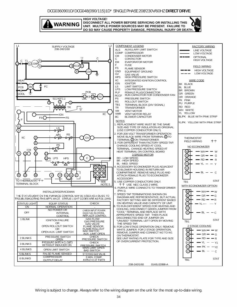
34
Wiring is subject to change. Always refer to the wiring diagram on the unit for the most up-to-date wiring.
HIGH VOLTAGE!DISCONNECT ALL POWER BEFORE SERVICING OR INSTALLING THISUNIT. MULTIPLE POWER SOURCES MAY BE PRESENT. FAILURE TODO SO MAY CAUSE PROPERTY DAMAGE, PERSONAL INJURY OR DEATH.
DCG0360901D/DCG048(090/115)1D* SINGLE PHASE 208/230V/60HZ DIRECT DRIVE
2. FOR 208 VOLT TRANSFORMER OPERATION MOVE BLACK WIRE FROM TERMINAL 3 TO TERMINAL 2 ON TRANSFORMER.
1. REPLACEMENT WIRE MUST BE THE SAME SIZE AND TYPE OF INSULATION AS ORIGINAL. (USE COPPER CONDUCTOR ONLY).
AUXILLARY LIMIT SWITCH
FEMALE PLUG/CONNECTOR
INTEGRATED IGNITION CONTROL
LS4
INSTALLER/SERVICEMAN
STATUS LIGHT
3 BLINKS
6 BLINKS
2 BLINKS
4 BLINKS
5 BLINKS
OFF
ON
1 BLINK
FALSE FLAME SENSED
OUTPUT DELAY
OPEN LIMIT SWITCH
COMPRESSOR
WITHOUT INDUCER ON
PRESSURE SWITCHOPEN
IGNITION FAILUREOR
OPEN ROLLOUT SWITCHOR
OPEN AUX. LIMIT SWITCH
NORMAL OPERATIONNO POWER OR
INTERNALCONTROL
EQUIP. STATUS
TO THERMOSTATTERMINAL BLOCK
GR
5
79
IIC
Y1W Y2
3
6
1210
8
11
RSALS
PS
BAD SWITCHAUX. LIMIT OPEN
MAIN LIMIT OPENBAD SWITCH
3 MIN. COMP.
PRESSURE SWITCH
PRESSURE SWITCHCHECK
CHECK
GAS PRESSURE
FLAME ROLLOUTFLAME SENSOR
GAS VALVE
GAS FLOW
CHECK-
C
GV
C
CM CONDENSER MOTOR
LS LIMIT SWITCH
VENT MOTOR RELAYVENT MOTOR
PRESSURE SWITCH
TERMINAL BLOCK (24V SIGNAL)ROLLOUT SWITCH
VMRVM
PS
PLF
TB1RS
NOTES
CONTACTOR
GAS VALVE
IGNITOR
EQUIPMENT GROUNDFLAME SENSOR
EVAPORATOR MOTORFUSEF
C
GV
FSGND
IGNIIC
EM
COMPRESSOR
COMPONENT LEGEND
COMPALS
TR TRANSFORMER
208-240/1/60 0140L02898-A
HPSLPS
HPS HIGH PRESSURE SWITCH
HIGH VOLTAGE
FACTORY WIRING
OPTIONAL HIGH VOLTAGE
LOW VOLTAGE
FIELD WIRING
LINE VOLTAGE
LOW VOLTAGE
BL
RDY1
YL
W
BL
GR
W
NO ECONOMIZER
G
YL
RDY1
PK
WH
W
R RD
WHGR
C
RYL
GR
Y1
GWH
WITH ECONOMIZER OPTION
C
GR
THERMOSTATFIELD WIRING
BL
C
2 STAGE COOLING
TB1
GR
W
Y
C
TB1
TB1
Y
W
RG
C
W
Y2
GR
C
Y1
STAT
STAT
STAT
BL/PK BLUE WITH PINK STRIP
YL/PK YELLOW WITH PINK STRIP
GR GREEN
WIRE CODE
BL BLUE
PU PURPLEPK PINK
WH WHITE
BK BLACK
RD RED
BR BROWN
OR ORANGE
YL YELLOWIICFS
TR
FSF
IGN
2 13
3. FOR DIFFERENT THAN FACTORY SPEED TAP. CHANGE COOLING SPEED AT COOL TERMINAL. CHANGE HEATING SPEED AT HEAT TERMINAL ON CONTROL BOARD
4. ACCESSORY ECONOMIZER PLUG ADJACENT TO BLOWER HOUSING IN RETURN AIR COMPARTMENT. REMOVE MALE PLUG AND ATTACH FEMALE PLUG TO ECONOMIZER ACCESSORY.
USE NEC CLASS 2 WIRE.5. USE COPPER CONDUCTORS ONLY.
7. SPEED TAP TERMINATIONS SHOWN ON DIAGRAM ARE REPRESENTATIVE, BUT ACTUAL FACTORY SETTING MAY BE DIFFERENT BASED ON HEATING VALUE AND CAPACITY OF UNIT.
6. PURPLE WIRE CONNECTS TO TRANSFORMER (PIN 1).
9. FOR LOW STAGE OPERATION ONLY, REMOVE WHITE JUMPER. FOR 2 STAGE OPERATION, REMOVE JUMPER AND CONNECT W2 TO W1 ON THERMOSTAT.
SEE UNIT RATING PLATE FOR TYPE AND SIZEOF OVERCURRENT PROTECTION.
BLOWER CAPACITORBC
L2
L2
SUPPLY VOLTAGE208-240/1/60
L1
C T1
EM
CR
S H C
CMF
C
VMLI
PCB
HEAT
COOL
FCPCB
DI
8. TO RUN DIFFERENT SPEED FOR HEATING AND COOLING, DISCONNECT GEEEN JUMPER FROM "COOL" TERMINAL AND REPLACE WITH APPROPRIATE SPEED TAP. THEN PLACE DISCONNECTED END OF JUMPER ON "UNUSED" TERMINAL LEFT OPEN BY MOVING THE SPEED TAP.
RUN CAPACITOR FOR CONDENSER FANRCCF
LPS LOW PRESSURE SWITCH
BK - HIGH SPEEDBL - MED. SPEED
RD - LOW SPEED3 SPEED MOTOR
32
6
7
9
1 485
S2S1
SEENOTE 5
Y2
Y2
Y2
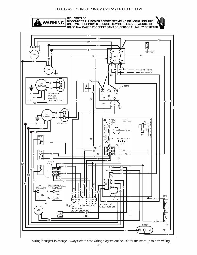
35
HIGH VOLTAGE!DISCONNECT ALL POWER BEFORE SERVICING OR INSTALLING THISUNIT. MULTIPLE POWER SOURCES MAY BE PRESENT. FAILURE TODO SO MAY CAUSE PROPERTY DAMAGE, PERSONAL INJURY OR DEATH.
Wiring is subject to change. Always refer to the wiring diagram on the unit for the most up-to-date wiring.
DCG0360451D* SINGLE PHASE 208/230V/60HZ DIRECT DRIVE
GND
YL
208-240/1/60SEE NOTE 5
RD
YL RD
IIC
C RD
YL
L2C
T2
L1
T1
BK
BK
PU
RD
OR
YL
SEE NOTE 8GREEN JUMPER
ALS
GR
PS
RSPLF
YL
YL
NOTE 4
GAS VALVE
MV
BL
W. R.GAS VALVE
PU
(ALT.) HONEYWELL
BR
PU
PU
PU
BK
BR
R GY1W1
ORRD
CMV
FS
IGN
VM
BL
RD
BL
BK
GVGV
TB1
YL
GR
S2
321
RD
RDLS
208TR
BL
24V
C
PK
240
BL
RD
PU
BK
BL/PK
YL/PK
HPS
LPS
BL
GR
BK
BR
RD
PU
EM
BL
3 SPEED
PU
PUBR
CM
BK
ALTERNATEMOTOR6-WIRESSEE NOTE 6 & 7
BC
BC3 SPEED
BL
EM
RD
BK
BR
RD
PU
COMP
SEE NOTE 7
RD
BK
YL
F H
YL
BL
RCCF
BL
5 841
9
7
623
R
PU
Y2S1
FOR SMOKE/FIREDETECTOR JUMPER
ORRDFS
IGN
DETECTOR JUMPER

36
Wiring is subject to change. Always refer to the wiring diagram on the unit for the most up-to-date wiring.
HIGH VOLTAGE!DISCONNECT ALL POWER BEFORE SERVICING OR INSTALLING THISUNIT. MULTIPLE POWER SOURCES MAY BE PRESENT. FAILURE TODO SO MAY CAUSE PROPERTY DAMAGE, PERSONAL INJURY OR DEATH.
DCG0360451D* SINGLE PHASE 208/230V/60HZ DIRECT DRIVE
2. FOR 208 VOLT TRANSFORMER OPERATION MOVE BLACK WIRE FROM TERMINAL 3 TO TERMINAL 2 ON TRANSFORMER.
1. REPLACEMENT WIRE MUST BE THE SAME SIZE AND TYPE OF INSULATION AS ORIGINAL. (USE COPPER CONDUCTOR ONLY).
AUXILLARY LIMIT SWITCH
FEMALE PLUG/CONNECTOR
INTEGRATED IGNITION CONTROL
LS4
INSTALLER/SERVICEMAN
STATUS LIGHT
3 BLINKS
6 BLINKS
2 BLINKS
4 BLINKS
5 BLINKS
OFFON
1 BLINK
OPEN AUX. LIMIT
FALSE FLAME SENSED
OUTPUT DELAY
OPEN LIMIT SWITCH
COMPRESSOR
WITHOUT INDUCER ON
PRESSURE SWITCHSWITCH
OPEN
OPEN ROLLOUTSWITCH
IGNITION FAILURE
NORMAL OPERATIONNO POWER OR
INTERNAL CONTROL
EQUIP. STATUS
OR
OR
FAULT
TO THERMOSTATTERMINAL BLOCK
GR
5
79
IIC
Y1W Y2
3
6
1210
8
11
RSALS
PS
BAD SWITCHAUX. LIMIT OPEN
MAIN LIMIT OPENBAD SWITCH
3 MIN. COMP.
PRESSURE SWITCH
PRESSURE SWITCHCHECK
CHECK
GAS PRESSURE
FLAME ROLLOUTFLAME SENSOR
GAS VALVE
GAS FLOW
CHECK-
C
GV
C
CM CONDENSER MOTOR
LS LIMIT SWITCH
VENT MOTORRELAYVENT MOTOR
PRESSURE SWITCH
TERMINAL BLOCK (24V SIGNAL)ROLLOUT SWITCH
VMRVM
PSPLF
TB1RS
NOTES
CONTACTOR
GAS VALVE
IGNITOR
EQUIPMENT GROUNDFLAME SENSOR
EVAPORATOR MOTORFUSEF
C
GV
FSGND
IGNIIC
EM
COMPRESSOR
COMPONENT LEGEND
COMPALS
TB1
TR TRANSFORMER
208-240/1/60 0140L02900-A
HPSLPS
HPS HIGH PRESSURE SWITCH
HIGH VOLTAGE
FACTORY WIRING
OPTIONAL HIGH VOLTAGE
LOW VOLTAGE
FIELD WIRING
LINE VOLTAGE
LOW VOLTAGE
BL
RDY1
YL
W
BL
GR
W
NO ECONOMIZER
G
YL
RD
Y2
Y1
PK
WH
W
R RD
WHGR
C
RYL
GR
Y1
GWH
WITH ECONOMIZER OPTION
C
GR
THERMOSTATFIELD WIRING
BL
C
2 STAGE COOLING
TB1
GR
W
Y
C
TB1
TB1
Y
W
RG
C
W
Y2
GR
C
Y1
STAT
STAT
STAT
BL/PK BLUE WITH PINK STRIP
YL/PK YELLOW WITH PINK STRIP
GR GREEN
WIRE CODE
BL BLUE
PU PURPLEPK PINK
WH WHITE
BK BLACK
RD RED
BR BROWN
OR ORANGE
YL YELLOWTB1
IICFS
TR
FSF
IGN
2 13
3. FOR DIFFERENT THAN FACTORY SPEED TAP. CHANGE COOLING SPEED AT COOL TERMINAL. CHANGE HEATING SPEED AT HEAT TERMINAL ON CONTROL BOARD
4. ACCESSORY ECONOMIZER PLUG ADJACENT TO BLOWER HOUSING IN RETURN AIR COMPARTMENT. REMOVE MALE PLUG AND ATTACH FEMALE PLUG TO ECONOMIZER ACCESSORY.
USE NEC CLASS 2 WIRE.5. USE COPPER CONDUCTORS ONLY.
7. SPEED TAP TERMINATIONS SHOWN ON DIAGRAM ARE REPRESENTATIVE, BUT ACTUAL FACTORY SETTING MAY BE DIFFERENT BASED ON HEATING VALUE AND CAPACITY OF UNIT.
6. PURPLE WIRE CONNECTS TO TRANSFORMER (PIN 1).
SEE UNIT RATING PLATE FOR TYPE AND SIZEOF OVERCURRENT PROTECTION.
BLOWER CAPACITORBC
L2
L2
SUPPLY VOLTAGE208-240/1/60
L1
C T1
EM
CR
S H C
CMF
C
VMLI
PCB
HEAT
COOL
FCPCB
DI
8. TO RUN DIFFERENT SPEED FOR HEATING AND COOLING, DISCONNECT GEEEN JUMPER FROM "COOL" TERMINAL AND REPLACE WITH APPROPRIATE SPEED TAP. THEN PLACE DISCONNECTED END OF JUMPER ON "UNUSED" TERMINAL LEFT OPEN BY MOVING THE SPEED TAP.
RUN CAPACITOR FOR CONDENSER FANRCCF
LPS LOW PRESSURE SWITCH
BK - HIGH SPEEDBL - MED. SPEEDRD - LOW SPEED3 SPEED MOTOR
5 841
9
7
623
S2S1
SEENOTE 4
PLF
Y2
Y2
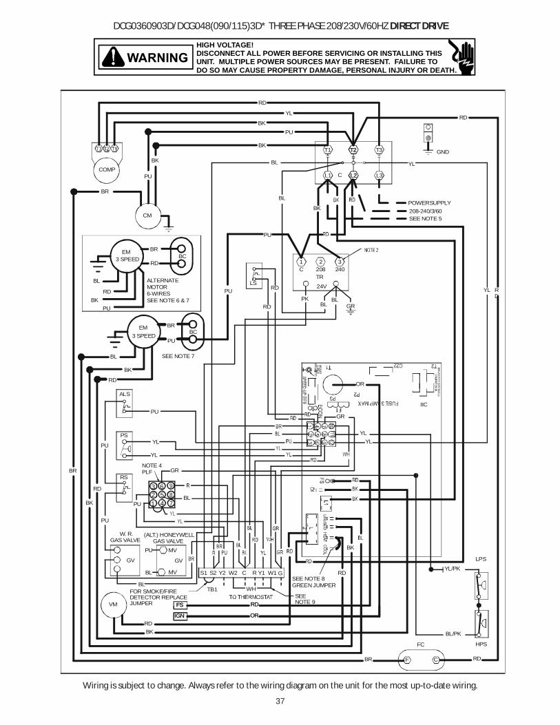
37
Wiring is subject to change. Always refer to the wiring diagram on the unit for the most up-to-date wiring.
HIGH VOLTAGE!DISCONNECT ALL POWER BEFORE SERVICING OR INSTALLING THISUNIT. MULTIPLE POWER SOURCES MAY BE PRESENT. FAILURE TODO SO MAY CAUSE PROPERTY DAMAGE, PERSONAL INJURY OR DEATH.
DCG0360903D/DCG048(090/115)3D* THREE PHASE 208/230V/60HZ DIRECT DRIVE
GND
YL
208-240/3/60SEE NOTE 5
RD
YL RD
IIC
C RD
RD
L2C
T2
L1
T1
BK
BK
PU
YL
OR
YL
SEE NOTE 8GREEN JUMPER
ALS
GR
PS
RSPLF
YL
YL
NOTE 4
GAS VALVEMV
BL
W. R.GAS VALVE
PU
(ALT.) HONEYWELL
BR
PU
PU
PU
BK
BR
R GY1 W1
OR
RD
CMV
FS
IGN
VM
BL
RD
BL
BK
GVGV
TB1
YL
GR
Y2
321
RD
RDLS
208TR
BL
24V
C
PK
240
BL
RD
PU
BK
BL/PK
YL/PK
HPS
LPS
BL
GR
BK
BR
RD
PU
EM
BL
3 SPEED
PU
PU
BR
CM
BK
ALTERNATEMOTOR6-WIRESSEE NOTE 6 & 7
BC
BC3 SPEED
BL
EM
RD
BK
BR
RD
PU
COMP
SEE NOTE 7
RD
BK
F
W2
L2
T2
L3
T3
POWERSUPPLY
FC
WH
BL
S2S1
32
6
7
9
1 485
PU
SEENOTE 9
FOR SMOKE/FIREDETECTOR REPLACEJUMPER
OR
RDFS
IGN

38
Wiring is subject to change. Always refer to the wiring diagram on the unit for the most up-to-date wiring.
HIGH VOLTAGE!DISCONNECT ALL POWER BEFORE SERVICING OR INSTALLING THISUNIT. MULTIPLE POWER SOURCES MAY BE PRESENT. FAILURE TODO SO MAY CAUSE PROPERTY DAMAGE, PERSONAL INJURY OR DEATH.
DCG0360903D/DCG048(090/115)3D* THREE PHASE 208/230V/60HZ DIRECT DRIVE
2. FOR 208 VOLT TRANSFORMER OPERATION MOVE BLACK WIRE FROM TERMINAL 3 TO TERMINAL 2 ON TRANSFORMER.
1. REPLACEMENT WIRE MUST BE THE SAME SIZE AND TYPE OF INSULATION AS ORIGINAL. (USE COPPER CONDUCTOR ONLY).
AUXILLARY LIMIT SWITCH
FEMALE PLUG/CONNECTOR
INTEGRATED IGNITION CONTROL
INSTALLER/SERVICEMAN
STATUS LIGHT
3 BLINKS
6 BLINKS
2 BLINKS
4 BLINKS
5 BLINKS
OFF
ON
1 BLINK
OPEN AUX. LIMIT
FALSE FLAME SENSED
OUTPUT DELAY
OPEN LIMIT SWITCH
COMPRESSOR
WITHOUT INDUCER ON
PRESSURE SWITCHSWITCH
OPEN
OPEN ROLLOUTSWITCH
IGNITION FAILURE
NORMAL OPERATIONNO POWER OR
INTERNAL CONTROL
EQUIP. STATUS
OR
OR
FAULT
BAD SWITCHAUX. LIMIT OPEN
MAIN LIMIT OPENBAD SWITCH
3 MIN. COMP.
PRESSURE SWITCH
PRESSURE SWITCHCHECK
CHECK
GAS PRESSURE
FLAME ROLLOUTFLAME SENSOR
GAS VALVE
GAS FLOW
CHECK-
PLF
GV
C
L1208-240/3/60
SUPPLY VOLTAGE
CM CONDENSER MOTOR
L3
LS LIMIT SWITCH
VENT MOTOR RELAYVENT MOTOR
PRESSURE SWITCH
TERMINAL BLOCK (24V SIGNAL)ROLLOUT SWITCH
VMRVM
PSPLF
TB1RS
NOTES
FAN CAPACITOR
CONTACTOR
GAS VALVE
IGNITOR
EQUIPMENT GROUNDFLAME SENSOR
EVAPORATOR MOTOR
FCFUSEF
C
GV
FSGND
IGNIIC
EM
L2 L3
COMPRESSOR
COMPONENT LEGEND
COMPALS
TB1
TR TRANSFORMER
C
CM
T3T3
T2
FC
C T1T1
CT2
208-240/3/60 0140L02899-A
HPS HIGH PRESSURE SWITCH
HIGH VOLTAGE
FACTORY WIRING
OPTIONAL HIGH VOLTAGE
LOW VOLTAGE
FIELD WIRING
LINE VOLTAGE
LOW VOLTAGE
BL
RDY1
YL
W
BL
GR
W
NO ECONOMIZER
G
RDY1
PK
WH
W
R RD
WHGR
C
RYL
GR
Y1
GWH
WITH ECONOMIZER OPTION
C
GR
THERMOSTATFIELD WIRING
BL
C
2 STAGE COOLING
TB1
GR
W
C
TB1
TB1
Y
W
RG
C
W
Y2
GR
C
Y1
STAT
STAT
STAT
BL/PK BLUE WITH PINK STRIPYL/PK YELLOW WITH PINK STRIP
GR GREEN
WIRE CODE
BL BLUE
PU PURPLEPK PINK
WH WHITE
BK BLACK
RD RED
BR BROWN
OR ORANGE
YL YELLOW
EM
DI
PCB
HEAT
COOL
FCPCB
LI
IIC
2 13
3. FOR DIFFERENT THAN FACTORY SPEED TAP. CHANGE COOLING SPEED AT COOL TERMINAL. CHANGE HEATING SPEED AT HEAT TERMINAL ON CONTROL BOARD
4. ACCESSORY ECONOMIZER PLUG ADJACENT TO BLOWER HOUSING IN RETURN AIR COMPARTMENT. REMOVE MALE PLUG AND ATTACH FEMALE PLUG TO ECONOMIZER ACCESSORY.
USE NEC CLASS 2 WIRE.5. USE COPPER CONDUCTORS ONLY.
7. SPEED TAP TERMINATIONS SHOWN ON DIAGRAM ARE REPRESENTATIVE, BUT ACTUAL FACTORY SETTING MAY BE DIFFERENT BASED ON HEATING VALUE AND CAPACITY OF UNIT.
6. PURPLE WIRE CONNECTS TO TRANSFORMER (PIN 1).
8. TO RUN DIFFERENT SPEED FOR HEATING AND COOLING, DISCONNECT GEEEN JUMPER FROM "COOL" TERMINAL AND REPLACE WITH APPROPRIATE SPEED TAP. THEN PLACE DISCONNECTED END OF JUMPER ON "UNUSED" TERMINAL LEFT OPEN BY MOVING THE SPEED TAP.
9. FOR LOW STAGE OPERATION ONLY, REMOVE WHITE JUMPER. FOR 2 STAGE OPERATION, REMOVE JUMPER AND CONNECT W2 TO W1 ON THERMOSTAT.
BLOWER CAPACITORBC
SEE UNIT RATING PLATE FOR TYPE AND SIZE OFOVERCURRENT PROTECTION.
VM
IGN
FFS
TR
FS
TB1
LPS HPS
C
PS
ALS RS
11
8
10 12
6
3
Y2W Y1
9 7
5
R G
TO THERMOSTATTERMINAL BLOCK
4LS
LPS LOW PRESSURE SWITCH
BK - HIGH SPEEDBL - MED. SPEEDRD - LOW SPEED3 SPEED MOTOR
32
6
7
9
1 485
S1 S2
IIC
SEENOTE 4
Y2
YL Y
Y2
Y2

39Wiring is subject to change. Always refer to the wiring diagram on the unit for the most up-to-date wiring.
HIGH VOLTAGE!DISCONNECT ALL POWER BEFORE SERVICING OR INSTALLING THISUNIT. MULTIPLE POWER SOURCES MAY BE PRESENT. FAILURE TODO SO MAY CAUSE PROPERTY DAMAGE, PERSONAL INJURY OR DEATH.
DCG0360453D* THREE PHASE 208/230V/60HZ DIRECT DRIVE
GND
YL
208-240/3/60SEE NOTE 5
RD
YL RD
IIC
C RD
RD
L2C
T2
L1
T1
BK
BK
PU
YL
OR
YL
RD
RD
RD
BK
SEE NOTE 8GREEN JUMPER
BL
BK
YLYL
PU
BRBL
RD
PUWH GR
BL
ALS
GR
PS
RSPLF
YL
YL
NOTE 4
GAS VALVE
MV
21 4
5
YL
BL
W. R.GAS VALVE
PU
(ALT.) HONEYWELL
3 6
YL
BR
PU
PU
PU
BK
BR
ORRD
MV
FSIGN
VM
BL
RD
BL
BK
GVGV
TB1
PU
BL
YL
GR
YL
321
RD
RDLS
208TR
BL
24V
C
PK
240
BL
RD
PU
BK
RDRD
BL
FOR SMOKE/FIREDETECTORREPLACE JUMPER
BL/PK
YL/PK
HPS
LPS
BL
GR
BK
BR
RD
PU
EM
BL
3 SPEED
PU
PU
BR
CM
BK
ALTERNATEMOTOR6-WIRESSEE NOTE 6 & 7
BC
BC3 SPEED
BL
EM
RD
BK
BR
RD
PU
COMP
SEE NOTE 7
RD
BK
F
L2
T2
L3
T3
POWERSUPPLY
FC
789
Y2 Y1S1S2 RC W1 GW2
RD
BL
BRPK
ORRDFS
IGNREPLACE JUMPER
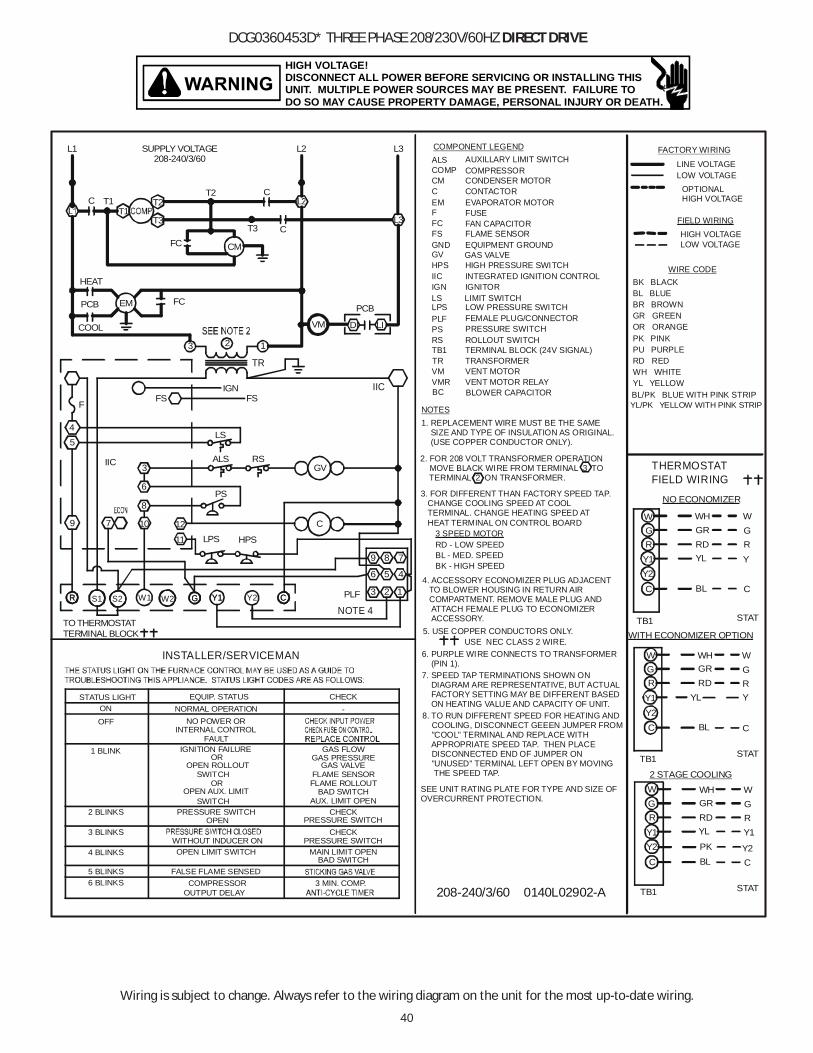
40
Wiring is subject to change. Always refer to the wiring diagram on the unit for the most up-to-date wiring.
HIGH VOLTAGE!DISCONNECT ALL POWER BEFORE SERVICING OR INSTALLING THISUNIT. MULTIPLE POWER SOURCES MAY BE PRESENT. FAILURE TODO SO MAY CAUSE PROPERTY DAMAGE, PERSONAL INJURY OR DEATH.
DCG0360453D* THREE PHASE 208/230V/60HZ DIRECT DRIVE
2. FOR 208 VOLT TRANSFORMER OPERATION MOVE BLACK WIRE FROM TERMINAL 3 TO TERMINAL 2 ON TRANSFORMER.
1. REPLACEMENT WIRE MUST BE THE SAME SIZE AND TYPE OF INSULATION AS ORIGINAL. (USE COPPER CONDUCTOR ONLY).
AUXILLARY LIMIT SWITCH
FEMALE PLUG/CONNECTOR
INTEGRATED IGNITION CONTROL
LS4
INSTALLER/SERVICEMAN
STATUS LIGHT
3 BLINKS
6 BLINKS
2 BLINKS
4 BLINKS
5 BLINKS
OFFON
1 BLINK
OPEN AUX. LIMIT
FALSE FLAME SENSED
OUTPUT DELAY
OPEN LIMIT SWITCH
COMPRESSOR
WITHOUT INDUCER ON
PRESSURE SWITCHSWITCH
OPEN
OPEN ROLLOUTSWITCH
IGNITION FAILURE
NORMAL OPERATIONNO POWER OR
INTERNAL CONTROL
EQUIP. STATUS
OR
OR
FAULT
5
79
IIC 3
6
1210
8
11
RSALS
PS
BAD SWITCHAUX. LIMIT OPEN
MAIN LIMIT OPENBAD SWITCH
3 MIN. COMP.
PRESSURE SWITCH
PRESSURE SWITCHCHECK
CHECK
GAS PRESSURE
FLAME ROLLOUTFLAME SENSOR
GAS VALVE
GAS FLOW
CHECK-
PLF
NOTE 4
4
3 2 1
56
GV
C
L1208-240/3/60
SUPPLY VOLTAGE
CM CONDENSER MOTOR
L3
LS LIMIT SWITCH
VENT MOTOR RELAYVENT MOTOR
PRESSURE SWITCH
TERMINAL BLOCK (24V SIGNAL)ROLLOUT SWITCH
VMRVM
PSPLF
TB1RS
NOTES
FAN CAPACITOR
CONTACTOR
GAS VALVE
IGNITOR
EQUIPMENT GROUNDFLAME SENSOR
EVAPORATOR MOTOR
FCFUSEF
C
GV
FSGND
IGNIIC
EM
L2 L3
COMPRESSOR
COMPONENT LEGEND
COMPALS
TR TRANSFORMER
C
CM
T3T3
T2
FC
C T1T1
CT2
208-240/3/60 0140L02902-A
HPSLPS
HPS HIGH PRESSURE SWITCH
HIGH VOLTAGE
FACTORY WIRING
OPTIONAL HIGH VOLTAGE
LOW VOLTAGE
FIELD WIRING
LINE VOLTAGE
LOW VOLTAGE
BL
RDY1
YL
W
BL
GR
W
NO ECONOMIZER
G
YL
RD
Y2
Y1
PK
WH
W
R RD
WHGR
C
RYL
GR
Y1
GWH
WITH ECONOMIZER OPTION
C
GR
THERMOSTATFIELD WIRING
BL
C
2 STAGE COOLING
TB1
GR
W
Y
C
TB1
TB1
Y
W
RG
C
W
Y2
GR
C
Y1
STAT
STAT
STAT
BL/PK BLUE WITH PINK STRIPYL/PK YELLOW WITH PINK STRIP
GR GREEN
WIRE CODE
BL BLUE
PU PURPLEPK PINK
WH WHITE
BK BLACK
RD RED
BR BROWN
OR ORANGE
YL YELLOW
EM
DI
PCB
HEAT
COOL
FCPCB
LI
IICFS
TR
FSF
IGN
2 13
VM
3. FOR DIFFERENT THAN FACTORY SPEED TAP. CHANGE COOLING SPEED AT COOL TERMINAL. CHANGE HEATING SPEED AT HEAT TERMINAL ON CONTROL BOARD
4. ACCESSORY ECONOMIZER PLUG ADJACENT TO BLOWER HOUSING IN RETURN AIR COMPARTMENT. REMOVE MALE PLUG AND ATTACH FEMALE PLUG TO ECONOMIZER ACCESSORY.
USE NEC CLASS 2 WIRE.5. USE COPPER CONDUCTORS ONLY.
7. SPEED TAP TERMINATIONS SHOWN ON DIAGRAM ARE REPRESENTATIVE, BUT ACTUAL FACTORY SETTING MAY BE DIFFERENT BASED ON HEATING VALUE AND CAPACITY OF UNIT.
6. PURPLE WIRE CONNECTS TO TRANSFORMER (PIN 1).
BLOWER CAPACITORBC
SEE UNIT RATING PLATE FOR TYPE AND SIZE OFOVERCURRENT PROTECTION.
8. TO RUN DIFFERENT SPEED FOR HEATING AND COOLING, DISCONNECT GEEEN JUMPER FROM "COOL" TERMINAL AND REPLACE WITH APPROPRIATE SPEED TAP. THEN PLACE DISCONNECTED END OF JUMPER ON "UNUSED" TERMINAL LEFT OPEN BY MOVING THE SPEED TAP.
LPS LOW PRESSURE SWITCH
BK - HIGH SPEEDBL - MED. SPEEDRD - LOW SPEED3 SPEED MOTOR
789
TO THERMOSTATTERMINAL BLOCK
GR Y1 CGR W1 Y2Y1 CW2S1 S2
Y2
Y2
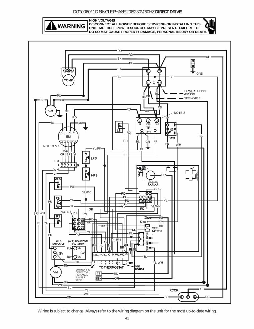
41
Wiring is subject to change. Always refer to the wiring diagram on the unit for the most up-to-date wiring.
HIGH VOLTAGE!DISCONNECT ALL POWER BEFORE SERVICING OR INSTALLING THISUNIT. MULTIPLE POWER SOURCES MAY BE PRESENT. FAILURE TODO SO MAY CAUSE PROPERTY DAMAGE, PERSONAL INJURY OR DEATH.
DCG0060*1D SINGLE PHASE 208/230V/60HZ DIRECT DRIVE
RCCF
FSIGN
VM
F H C
SEENOTE 8
RCCF
RDBR
ORRDFS
IGN
VM
BL
YLWH
BR
BL
SMOKE/FIREDETECTORREPLACESJUMPERWIRE
YL
F H C
BK
SEENOTE 8
WH
OROR
SEESEENOTE 8NOTE 8
POWER SUPPLY240/1/60
BL
L2C
T2
L1
T1
NOTE 2
COMP
CM
VMR
C
24VTR
LS
NOTE 6SEE
ALS
PS
RS
GAS VALVE
MV
21 4
5
W. R.GAS VALVE
(ALT.) HONEYWELL
3 6
1 2 3
MVGVGV
TB1
LPS
HPS
1 5
EM
Y2Y1
GNDYL
RD
YL
WH
RD
YL
RD
BK
BKRD
BL
BK
BK
PU
RD
COMP
BKPU
CM
BR
PK
240
PKVMR
BL
C
24VTR
BL
208
OR
LSRD
RD
WH
GR
YLRD
NOTE 6SEE
YLYL
PU
RDBL
BLBL
GR
ALS
GR
PS
RSPLF
YL
YL
NOTE 4
GAS VALVE
MV
21 4
5
YL
BL
W. R.GAS VALVE
PU
(ALT.) HONEYWELL
3 6
YLBR WH
BL YL
PU
PU
PU
1 2 3
MVBLGVGV
TB1
PU
WHYL
LPS
HPS
YL/PK
1 5
BL
NOTE 3 & 7
G
T4
EML
T3T2T1
C
RD
BK
N
T5
YLWH
TB1
YL/PK
GR
S1S2 RC W1 GW2
RD
BK
BK
YLPU
BRWH
OR
SEE NOTE 5
3
1
2
789 RD
RD
YLYL
PU
RDBL
BLBLBL
RD
TB1TB1
W1 GW2

42
Wiring is subject to change. Always refer to the wiring diagram on the unit for the most up-to-date wiring.
HIGH VOLTAGE!DISCONNECT ALL POWER BEFORE SERVICING OR INSTALLING THISUNIT. MULTIPLE POWER SOURCES MAY BE PRESENT. FAILURE TODO SO MAY CAUSE PROPERTY DAMAGE, PERSONAL INJURY OR DEATH.
DCG0060*1D SINGLE PHASE 208/230V/60HZ DIRECT DRIVE
AUXILIARY LIMIT SWITCH
FEMALE PLUG/CONNECTOR
INTEGRATED IGNITION CONTROL
VMRLS4
INSTALLER/SERVICEMAN
STATUS LIGHT
3 BLINKS
6 BLINKS
2 BLINKS
4 BLINKS
5 BLINKS
OFFON
1 BLINK
OPEN AUX. LIMIT
FALSE FLAME SENSED
OUTPUT DELAY
OPEN LIMIT SWITCH
COMPRESSOR
WITHOUT INDUCER ON
PRESSURE SWITCHSWITCH
OPEN
OPEN ROLLOUTSWITCH
IGNITION FAILURE
NORMAL OPERATIONNO POWER OR
INTERNAL CONTROL
EQUIP. STATUS
OR
OR
FAULT
GR
5
79
Y2Y1
3
6
1210
8
11
RSALS
PS
BAD SWITCHAUX. LIMIT OPEN
MAIN LIMIT OPENBAD SWITCH
3 MIN. COMP.
PRESSURE SWITCH
PRESSURE SWITCHCHECK
CHECK
GAS PRESSURE
FLAME ROLLOUTFLAME SENSOR
GAS VALVE
GAS FLOW
CHECK-
C
4
3 2 1
56
GV
IGN
NOTE 6L1
F
HC
D1
FS
TR
CM CONDENSER MOTOR
NOTE 6
CEM
FSIIC
L2
LS LIMIT SWITCH
VENT MOTOR RELAYVENT MOTOR
PRESSURE SWITCH
TERMINAL BLOCK (24V SIGNAL)ROLLOUT SWITCH
VMRVM
PSPLF
TB1RS
CONTACTOR
GAS VALVE
IGNITOR
EQUIPMENT GROUNDFLAME SENSOR
EVAPORATOR MOTOR
RCCF
FUSEF
C
GV
FSGND
IGNIIC
EM
COMPRESSORCOMPALS
TB1
TB1
TB1
TR TRANSFORMER
C
L2
L2
VMR
SUPPLY VOLTAGE240/1/60
L1
2 13
C T1
EML N
CR
S H C
CM
VM
C
LPS HPS
HIGH PRESSURE SWITCHHPS
LOW PRESSURE SWITCHLPS
COOLING SPEED (YELLOW WIRE)
3. FOR DIFFERENT THAN FACTORY SPEED TAP. CHANGE COOLING SPEED AT MOTOR T4 AND T5 TERMINALS. CHANGE HEATING SPEED AT MOTOR T1. T2, AND T3 TERMINALS
4. ACCESSORY ECONOMIZER PLUG ADJACENT TO BLOWER HOUSING IN RETURN AIR COMPARTMENT. REMOVE MALE PLUG AND ATTACH FEMALE PLUG TO ECONOMIZER ACCESSORY.
1. REPLACEMENT WIRE MUST BE THE SAME SIZE AND TYPE OF INSULATION AS ORIGINAL. (USE COPPER CONDUCTOR ONLY).
T3 - LOW SPEEDT4 - HIGH SPEED
NOTES
HEATING SPEED (WHITE WIRE)
T5 - HIGH SPEED (140)T2 - MED. SPEEDT1 - LOW SPEED (070)
HIGH VOLTAGE
FACTORY WIRING
LOW VOLTAGE
FIELD WIRING
LINE VOLTAGE
LOW VOLTAGE
BL
RD
YL
W
BL
GR
W
NO ECONOMIZER
G
RD
PK
WH
W
R RD
WHGR
C
RYL
GRGWH
WITH ECONOMIZER OPTION
C
GR
BL
C
2 STAGE COOLING
TB1
GR
W
C
TB1
TB1
Y
W
RG
C
W
Y2
GR
C
STAT
STAT
STAT
BL/PK BLUE WITH PINK STRIPYL/PK YELLOW WITH PINK STRIP
GR GREEN
WIRE CODE
BL BLUE
PU PURPLE
WH WHITE
BK BLACK
BR BROWN
OR ORANGE
YL YELLOW
6. L1 AND L2 ON ICC CONTROL IS 24V INPUT.7. SPEED TAP TERMINATIONS SHOWN ON DIAGRAM ARE REPRESENTATIVE, BUT ACTUAL FACTORY SETTINGS MAY BE DIFFERENT BASED ON THE HEATING VALUE OF THE UNIT.
8. FOR LOW STAGE OPERATION ONLY, REMOVE WHITE JUMPER. FOR 2 STAGE OPERATION, REMOVE JUMPER AND CONNECT W2 TO W2 ON THERMOSTAT.
3 1
AUXILIARY LIMIT SWITCH
FEMALE PLUG/CONNECTOR
INTEGRATED IGNITION CONTROL
VMRLS4
INSTALLER/SERVICEMAN
STATUS LIGHT
3 BLINKS
6 BLINKS
2 BLINKS
4 BLINKS
5 BLINKS
OFFON
1 BLINK
OPEN AUX. LIMIT
FALSE FLAME SENSED
OUTPUT DELAY
OPEN LIMIT SWITCH
COMPRESSOR
WITHOUT INDUCER ON
PRESSURE SWITCHSWITCH
OPEN
OPEN ROLLOUTSWITCH
IGNITION FAILURE
NORMAL OPERATIONNO POWER OR
INTERNAL CONTROL
EQUIP. STATUS
OR
OR
FAULT
TO THERMOSTATTERMINAL BLOCK
GR
5
79ECON
IIC
W1 Y1
3
6
1210
8
11
RSALS
PS
BAD SWITCHAUX. LIMIT OPEN
MAIN LIMIT OPENBAD SWITCH
3 MIN. COMP.
PRESSURE SWITCH
PRESSURE SWITCHCHECK
CHECK
GAS PRESSURE
FLAME ROLLOUTFLAME SENSOR
GAS VALVE
GAS FLOW
CHECK-
PLFCNOTE 4
4
3 2 1
56
GV
IGN
NOTE 6L1
F
HC
D1
FS
TR
CM CONDENSER MOTOR
NOTE 6
CEM
FSIIC
L2
LS LIMIT SWITCH
VENT MOTOR RELAYVENT MOTOR
PRESSURE SWITCH
TERMINAL BLOCK (24V SIGNAL)
VMRVM
PSPLF
TB1RS
RUN CAPACITOR FOR COMPRESSOR/FAN
CONTACTOR
GAS VALVE
IGNITOR
EQUIPMENT GROUNDFLAME SENSOR
EVAPORATOR MOTOR
RCCF
FUSEF
C
GV
FSGND
IGNIIC
EM
COMPRESSOR
COMPONENT LEGEND
COMPALS
TB1
TB1
TB1
TR TRANSFORMER
C
L2
L2
VMR
SUPPLY VOLTAGE240/1/60
L1
2 13
C T1
EML N
CR
S H C
CMF
VM
C
LPS HPS
HIGH PRESSURE SWITCHHPS
LOW PRESSURE SWITCHLPS
USE NEC CLASS 2 WIRE.5. USE COPPER CONDUCTORS ONLY.
T3 - LOW SPEEDT4 - HIGH SPEEDHEATING SPEED (WHITE WIRE)
T5 - HIGH SPEED (140)T2 - MED. SPEEDT1 - LOW SPEED (070)
240/1/60 0140L02912-A
HIGH VOLTAGE
FACTORY WIRING
LOW VOLTAGE
FIELD WIRING
LINE VOLTAGE
LOW VOLTAGE
BL
RDY1
YL
W
BL
GR
W
G
YL
RDY1
PK
WH
W
R RD
WHGR
C
RYL
GR
Y1
GWH
WITH ECONOMIZER OPTION
C
GR
THERMOSTATFIELD WIRING
BL
C
TB1
GR
W
Y
C
TB1
TB1
Y
W
RG
C
W
Y2
GR
C
Y1
STAT
STAT
STAT
WIRE CODE
PK PINK
RD RED
SEE UNIT RATING PLATE FOR TYPE AND SIZEOF OVER CURRENT PROTECTION .
W2
3 1
2. FOR 208 VOLT TRANSFORMER OPERATION MOVE BLACK WIRE FROM TERMINAL 3 TO TERMINAL 2 ON TRANSFORMER.
789
S1 S2
Y2
Y2
Y2
ROLLOUT SWITCH
COMPALS
3. FOR DIFFERENT THAN FACTORY SPEED TAP. CHANGE COOLING SPEED AT MOTOR T4 AND T5 TERMINALS. CHANGE HEATING SPEED AT
1. REPLACEMENT WIRE MUST BE THE SAME SIZE AND TYPE OF INSULATION AS ORIGINAL. (USE COPPER CONDUCTOR ONLY).
NOTES
AUXILIARY LIMIT SWITCHAUXILIARY LIMIT SWITCH
FEMALE PLUG/CONNECTORFEMALE PLUG/CONNECTOR
INTEGRATED IGNITION CONTROLINTEGRATED IGNITION CONTROL
CM CONDENSER MOTORCM CONDENSER MOTOR
IICIICL2L2L2
LS LIMIT SWITCHLS LIMIT SWITCH
VENT MOTOR RELAYVENT MOTOR RELAYVENT MOTORVENT MOTOR
PRESSURE SWITCHPRESSURE SWITCH
TERMINAL BLOCK (24V SIGNAL)TERMINAL BLOCK (24V SIGNAL)
VMRVMRVMVM
PSPSPLFPLF
TB1TB1RSRS
RUN CAPACITOR FOR COMPRESSOR/FAN
CONTACTORCONTACTOR
GAS VALVEGAS VALVE
IGNITORIGNITOR
EQUIPMENT GROUNDEQUIPMENT GROUNDFLAME SENSORFLAME SENSOR
EVAPORATOR MOTOREVAPORATOR MOTOR
RCCFRCCF
FUSEFUSEFF
CC
GVGV
FSFSGNDGND
IGNIGNIICIIC
EMEM
COMPRESSORCOMPRESSOR
COMPONENT L
COMPCOMPALSALSALS
TRTR TRANSFORMERTRANSFORMER
L2L2
L2L2L2L2L2
HIGH PRESSURE SWITCHHIGH PRESSURE SWITCHHPSHPS
LOW PRESSURE SWITCHLOW PRESSURE SWITCHLPSLPS
2. FOR 208 VOLT TRANSFORMER OPERATION MOVE BLACK WIRE FROM TERMINAL 3 TO TERMINAL 2 ON TRANSFORMER.
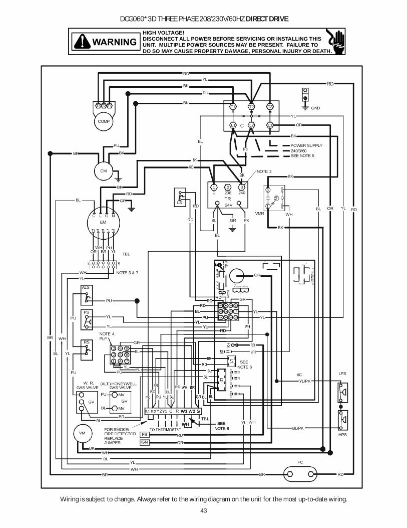
43
Wiring is subject to change. Always refer to the wiring diagram on the unit for the most up-to-date wiring.
HIGH VOLTAGE!DISCONNECT ALL POWER BEFORE SERVICING OR INSTALLING THISUNIT. MULTIPLE POWER SOURCES MAY BE PRESENT. FAILURE TODO SO MAY CAUSE PROPERTY DAMAGE, PERSONAL INJURY OR DEATH.
DCG060*3D THREE PHASE 208/230V/60HZ DIRECT DRIVE
GND
YL
BK
BK
POWER SUPPLY240/3/60
RD
WHBL
RD
L2C
T2 T3
L3L1
T1
BK
BK
PU
YL
COMP
BK
PU
CM
BR
VMR
OR
YL
RD
RD
YLYL
PU
RDBL
RD
ALS
GR
PS
RSPLF
YL
YL
NOTE 4BR WH
PU
PU
BK
YL
GR
TB1
WHYL
NOTE 3 & 7
1 5
321
RD
RDLS
208TR
BL
24V
C
BL PK
240
BL
NOTE 2
BL
GEMLC
GR
RDBK
NGR
WHYLBR
PUOR
3
1
2
OR
OR
SEE NOTE 5
YL RD
RD
YLYL
PU
RDBL
RD
RD
IIC
FC
RD
NOTE 6SEE
GAS VALVE
MV
21 4
5
YL
BL
W. R.GAS VALVE
PU
(ALT.) HONEYWELL
3 6
YL
BL YL
PU
WH
BR
OR
RD
MV
FS
IGN
VM
BL
BL
YL
WHBR
BL
BK
GVGV
FOR SMOKE/FIRE DETECTORREPLACEJUMPER
TB1
PU LPS
HPS
YL/PK
BL/PK
BR
NOTE 8SEE
WH
YL
789
Y2Y1S1 S2 RC W1 GW2
NOTE 8SEE
TB1
W1 GW1 GW2
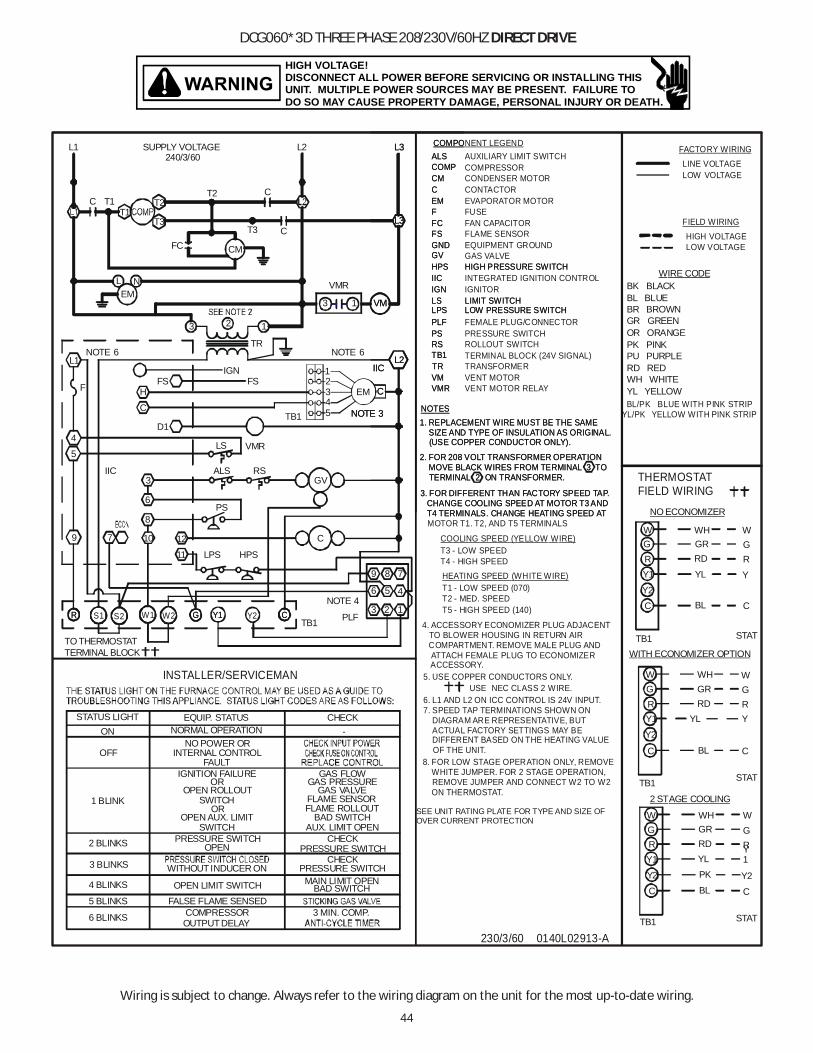
44
Wiring is subject to change. Always refer to the wiring diagram on the unit for the most up-to-date wiring.
HIGH VOLTAGE!DISCONNECT ALL POWER BEFORE SERVICING OR INSTALLING THISUNIT. MULTIPLE POWER SOURCES MAY BE PRESENT. FAILURE TODO SO MAY CAUSE PROPERTY DAMAGE, PERSONAL INJURY OR DEATH.
DCG060*3D THREE PHASE 208/230V/60HZ DIRECT DRIVE
COOLING SPEED (YELLOW WIRE)
USE NEC CLASS 2 WIRE.5. USE COPPER CONDUCTORS ONLY.
6. L1 AND L2 ON ICC CONTROL IS 24V INPUT.7. SPEED TAP TERMINATIONS SHOWN ON DIAGRAM ARE REPRESENTATIVE, BUT ACTUAL FACTORY SETTINGS MAY BE DIFFERENT BASED ON THE HEATING VALUE OF THE UNIT.
3. FOR DIFFERENT THAN FACTORY SPEED TAP. CHANGE COOLING SPEED AT MOTOR T3 AND T4 TERMINALS. CHANGE HEATING SPEED AT MOTOR T1. T2, AND T5 TERMINALS
4. ACCESSORY ECONOMIZER PLUG ADJACENT TO BLOWER HOUSING IN RETURN AIR COMPARTMENT. REMOVE MALE PLUG AND ATTACH FEMALE PLUG TO ECONOMIZER ACCESSORY.
1. REPLACEMENT WIRE MUST BE THE SAME SIZE AND TYPE OF INSULATION AS ORIGINAL. (USE COPPER CONDUCTOR ONLY).
AUXILIARY LIMIT SWITCH
FEMALE PLUG/CONNECTOR
INTEGRATED IGNITION CONTROL
LS4
INSTALLER/SERVICEMAN
STATUS LIGHT
3 BLINKS
6 BLINKS
2 BLINKS
4 BLINKS
5 BLINKS
OFF
ON
1 BLINK
OPEN AUX. LIMIT
FALSE FLAME SENSED
OUTPUT DELAY
OPEN LIMIT SWITCH
COMPRESSOR
WITHOUT INDUCER ON
PRESSURE SWITCHSWITCH
OPEN
OPEN ROLLOUTSWITCH
IGNITION FAILURE
NORMAL OPERATIONNO POWER OR
INTERNAL CONTROL
EQUIP. STATUS
OR
OR
FAULT
TO THERMOSTATTERMINAL BLOCK
5
79
IIC3
6
1210
8
11
RSALS
PS
BAD SWITCHAUX. LIMIT OPEN
BAD SWITCH
3 MIN. COMP.
PRESSURE SWITCH
PRESSURE SWITCHCHECK
CHECK
GAS PRESSURE
FLAME ROLLOUTFLAME SENSOR
GAS VALVE
GAS FLOW
CHECK-
PLF
NOTE 44
3 2 1
56
GV
CT3 - LOW SPEEDT4 - HIGH SPEED
IGN
NOTE 6L1
F
D1
FS
TR
L1240/3/60
SUPPLY VOLTAGE
CM CONDENSER MOTOR
NOTE 6
FSIIC
L2
VM1
VMR
L3
LS LIMIT SWITCH
VENT MOTOR RELAYVENT MOTOR
PRESSURE SWITCH
TERMINAL BLOCK (24V SIGNAL)ROLLOUT SWITCH
VMRVM
PSPLF
TB1RS
NOTES
FAN CAPACITOR
CONTACTOR
GAS VALVE
IGNITOR
EQUIPMENT GROUNDFLAME SENSOR
EVAPORATOR MOTOR
FCFUSEF
C
GV
FSGND
IGNIIC
EM
L2 L3
COMPRESSOR
COMPONENT LEGEND
COMPALS
HEATING SPEED (WHITE WIRE)
T5 - HIGH SPEED (140)T2 - MED. SPEEDT1 - LOW SPEED (070)
TB1
TR TRANSFORMER
EML
3 12
N
C
CM
T3T3
T2
FC
C T1T1
CT2
230/3/60 0140L02913-A
HPSLPS
HPS HIGH PRESSURE SWITCH
VMR
TB1 54
EM
1
32
CH
NOTE 3
HIGH VOLTAGE
FACTORY WIRING
LOW VOLTAGE
FIELD WIRING
LINE VOLTAGE
LOW VOLTAGE
BL
RD
Y1
YL
W
BL
GR
W
NO ECONOMIZER
G
YL
RD
Y2
Y1
PK
WH
W
R RD
WHGR
C
RYL
GR
Y1
GWH
WITH ECONOMIZER OPTION
C
GR
THERMOSTATFIELD WIRING
BL
C
2 STAGE COOLING
TB1
GR
W
Y
C
TB1
TB1
Y
W
RG
C
W
Y2
GR
C
Y1
STAT
STAT
STAT
BL/PK BLUE WITH PINK STRIPYL/PK YELLOW WITH PINK STRIP
GR GREEN
WIRE CODE
BL BLUE
PU PURPLEPK PINK
WH WHITE
BK BLACK
RD RED
BR BROWN
OR ORANGE
YL YELLOW
SEE UNIT RATING PLATE FOR TYPE AND SIZE OFOVER CURRENT PROTECTION
8. FOR LOW STAGE OPERATION ONLY, REMOVE WHITE JUMPER. FOR 2 STAGE OPERATION, REMOVE JUMPER AND CONNECT W2 TO W2 ON THERMOSTAT.
3
MAIN LIMIT OPEN
LPS LOW PRESSURE SWITCH
2. FOR 208 VOLT TRANSFORMER OPERATION MOVE BLACK WIRES FROM TERMINAL 3 TO TERMINAL 2 ON TRANSFORMER.
789
GR Y1 CGR W1 Y2Y1 CW2S1 S2
C
Y2
Y2
3. FOR DIFFERENT THAN FACTORY SPEED TAP. CHANGE COOLING SPEED AT MOTOR T3 AND T4 TERMINALS. CHANGE HEATING SPEED AT
1. REPLACEMENT WIRE MUST BE THE SAME SIZE AND TYPE OF INSULATION AS ORIGINAL. (USE COPPER CONDUCTOR ONLY).
CM
IICL2
VM
L3
LS LIMIT SWITCH
VMRVM
PSPLF
TB1RS
NOTES
FCF
C
GV
FSGND
IGNIIC
EM
L3 COMPO
COMPALS
TR
HPS HIGH PRESSURE SWITCH
C
NOTE 3
LPS LOW PRESSURE SWITCH
2. FOR 208 VOLT TRANSFORMER OPERATION MOVE BLACK WIRES FROM TERMINAL 3 TO TERMINAL 2 ON TRANSFORMER.
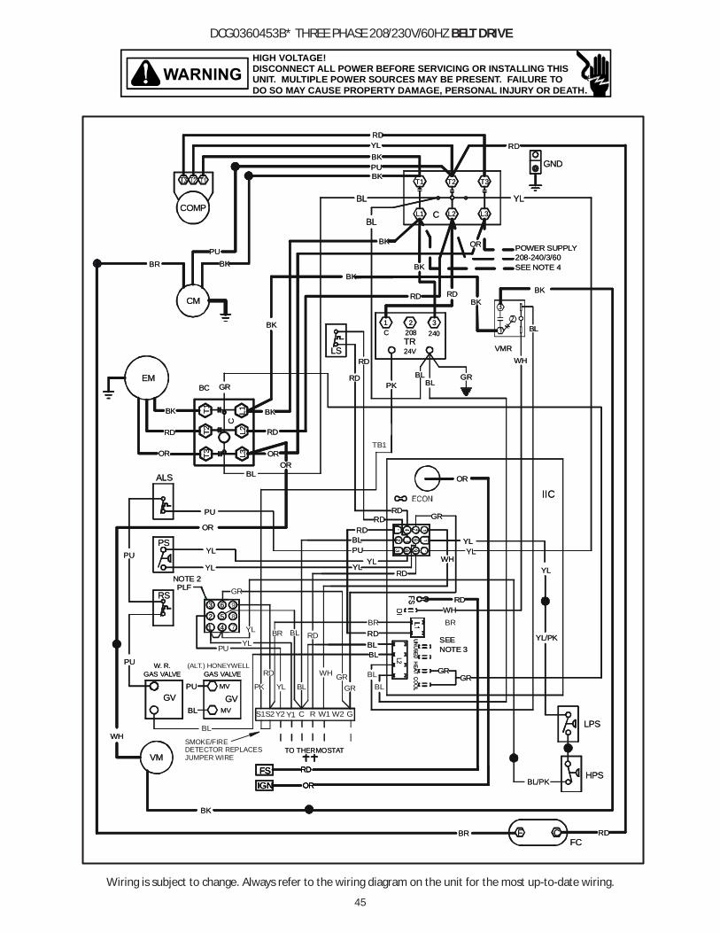
45
Wiring is subject to change. Always refer to the wiring diagram on the unit for the most up-to-date wiring.
HIGH VOLTAGE!DISCONNECT ALL POWER BEFORE SERVICING OR INSTALLING THISUNIT. MULTIPLE POWER SOURCES MAY BE PRESENT. FAILURE TODO SO MAY CAUSE PROPERTY DAMAGE, PERSONAL INJURY OR DEATH.
DCG0360453B* THREE PHASE 208/230V/60HZ BELT DRIVE
GND
T3
RD
L3
POWER SUPPLY
YL
BK
208-240/3/60
YL
IIC
T1 T2BKPU
YLBK
RD
CL1 L2BL
BL
RD RD
BK
PU
COMP
CM
BR BK
RD
RDLS
WH
GR
BLPU
RDRD
WHBR
YL
RD
BL
RDYL
YL
PU
YLPUPS
541
2
NOTE 2PLF
63
YL
RS
ALS
GR
BL
MV
MV
PU
PU W. R.GAS VALVE
GVBL
GAS VALVE
GV
GR
OR
RD
BK
OR
EM
WHVMR
BL
24VTR
BLBL
1240
2 3C
BK OR
RD
OR
BL
GR
SEENOTE 3
FSIGN
BK
VM
OR
RD
FCRDBR
RD
T2T3
T1
C
BC
BK
208
L3L2
L1
WH
YL
HPS
LPS
PK
TB1
YL/PK
BL/PK
GR
RD
TO THERMOSTAT
3
1
2
F C
OR
OR
SEE NOTE 4
BK
BK
BK
GND
T3
RD
L3
POWER SUPPLY
YL
BK
208-240/3/60
YL
IIC
T1 T2BKPU
YLBK
RD
CL1 L2BL
BL
RD RD
BK
PU
COMP
CM
BR BK
RD
RDLS
WH
GR
BLPU
RDRD
WHBR
YL
RD
BL
RDYL
YL
GR
YL
PU
YLPUPS
541
2
NOTE 2PLF
63
YL
RS
ALS
GR
BLYL
MV
MV
PU
PU W. R.GAS VALVE
GVBL
(ALT.) HONEYWELLGAS VALVE
GV
GR
OR
RD
BK
OR
EM
WHVMR
BL
24VTR
BLBL
1240
2 3C
BK OR
RD
OR
BL
GR
SEENOTE 3
FSIGN
BK
VM
OR
RD
FCRDBR
RD
T2T3
T1
C
BC
BK
208
L3L2
L1
WH
YL
HPS
LPS
PK
SMOKE/FIREDETECTOR REPLACESJUMPER WIRE
YL/PK
BL/PK
GR
BL
RD
YL BL
RD
TO THERMOSTAT
GR
BL
PU
WH
3
1
2
F C
OR
OR
SEE NOTE 4
BK
BK
BK
BLBL
87
9
Y2 Y1S1S2 RC W1 GW2
RD
PK
BR
GR
FSFSIGNIGN OROR
RDRD
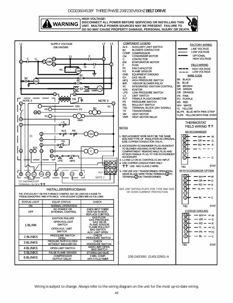
46
Wiring is subject to change. Always refer to the wiring diagram on the unit for the most up-to-date wiring.
HIGH VOLTAGE!DISCONNECT ALL POWER BEFORE SERVICING OR INSTALLING THISUNIT. MULTIPLE POWER SOURCES MAY BE PRESENT. FAILURE TODO SO MAY CAUSE PROPERTY DAMAGE, PERSONAL INJURY OR DEATH.
DCG0360453B* THREE PHASE 208/230V/60HZ BELT DRIVE
INSTALLER/SERVICEMAN
FALSE FLAME SENSED
OPEN LIMIT SWITCHWITHOUT INDUCER ON
PRESSURE SWITCH
NORMAL OPERATION
INTERNAL CONTROL
3 BLINKS
6 BLINKS
4 BLINKS5 BLINKS
OUTPUT DELAYCOMPRESSOR
OFF
ON
1 BLINK
2 BLINKS
STATUS LIGHT
OPEN AUX. LIMIT
IGNITION FAILUREOPEN ROLLOUT
SWITCH
OPEN
SWITCH
NO POWER OR
EQUIP. STATUS
CHECK
MAIN LIMIT OPENBAD SWITCH
3 MIN. COMP.
PRESSURE SWITCH
GAS PRESSURE
FLAME ROLLOUT
AUX. LIMIT OPEN
FLAME SENSOR
BAD SWITCH
GAS VALVE
GAS FLOW
PRESSURE SWITCHCHECK
-
CHECK
TRANSFORMERTR
ALS
COMP
COMPONENT LEGEND
COMPRESSOR
EM
IICIGN
GNDFS
GV
C
F FUSEFC
EVAPORATOR MOTOR
FLAME SENSOREQUIPMENT GROUND
IGNITOR
GAS VALVE
CONTACTOR
FAN CAPACITOR
RSTB1
PLFPS
VMVMR
ROLLOUT SWITCHTERMINAL BLOCK (24V SIGNAL)
PRESSURE SWITCH
VENT MOTORVENT MOTOR RELAY
LIMIT SWITCHLS
CONDENSER MOTORCM
INTEGRATED IGNITION CONTROL
FEMALE PLUG/CONNECTOR
AUXILIARY LIMIT SWITCH
IBR INDOOR BLOWER RELAY
BC BLOWER CONTACTOR
BC
L2 L3
CCM
T3
C
FC
208-240/3/60
T2
T3
T2T1
T1
L1
C
SUPPLY VOLTAGE
1
3VMR
BCIIC
VMR
FSIGN
NOTE 3
C
RSGV
3
6
2
5
1
EM
LS
H CD1
FS
5
4
NOTE 3
ALS
PS
10
3
6
8
12
11
9 7
TR
1
4
LPS HPS
LPS LOW PRESSURE SWITCH
HPS HIGH PRESSURE SWITCH
BC
BC
3. L1 AND L2 ON IIC CONTROL IS 24V INPUT.
USE NEC CLASS 2 WIRE.4. USE COPPER CONDUCTORS ONLY.
2. ACCESSORY ECONOMIZER PLUG ADJACENT TO BLOWER HOUSING IN RETURN AIR COMPARTMENT. REMOVE MALE PLUG AND ATTACH FEMALE PLUG TO THE ECONOMIZER ACCESSORY.
1. REPLACEMENT WIRE MUST BE THE SAME SIZE AND TYPE OF INSULATION AS ORIGINAL. (USE COPPER CONDUCTOR ONLY).
NOTES
LOW VOLTAGE
LINE VOLTAGE
FIELD WIRING
LOW VOLTAGE OPTIONAL HIGH VOLTAGE
FACTORY WIRING
HIGH VOLTAGE
BL
RDY1
YL
W
BL
GR
W
NO ECONOMIZER
G
RD
Y2
Y1
PK
WH
W
R RD
WHGR
C
RYL
GR
Y1
GWH
WITH ECONOMIZER OPTION
C
GR
THERMOSTATFIELD WIRING
BL
C
2 STAGE COOLING
TB1
GR
W
C
TB1
TB1
Y
W
RG
C
W
Y2
GR
C
Y1
STAT
STAT
STAT
BL/PK BLUE WITH PINK STRIPYL/PK YELLOW WITH PINK STRIP
GR GREEN
WIRE CODE
BL BLUE
PU PURPLEPK PINK
WH WHITE
BK BLACK
RD RED
BR BROWN
OR ORANGE
YL YELLOW
VM
5. FOR 208 VOLT TRANSFORMER OPERATION, MOVE BLACK WIRE FROM TERMINAL 3 TO TERMINAL 2 ON TRANSFORMER.
INSTALLER/SERVICEMAN
FALSE FLAME SENSED
OPEN LIMIT SWITCHWITHOUT INDUCER ON
PRESSURE SWITCH
NORMAL OPERATION
INTERNAL CONTROL
3 BLINKS
6 BLINKS
4 BLINKS5 BLINKS
OUTPUT DELAYCOMPRESSOR
OFF
ON
1 BLINK
2 BLINKS
STATUS LIGHT
OPEN AUX. LIMIT
IGNITION FAILUREOPEN ROLLOUT
SWITCH
OPEN
SWITCH
NO POWER OR
EQUIP. STATUS
CHECK
MAIN LIMIT OPENBAD SWITCH
3 MIN. COMP.
PRESSURE SWITCH
GAS PRESSURE
FLAME ROLLOUT
AUX. LIMIT OPEN
FLAME SENSOR
BAD SWITCH
GAS VALVE
GAS FLOW
PRESSURE SWITCHCHECK
-
CHECK
TRANSFORMERTR
ALS
COMP
COMPONENT LEGEND
COMPRESSOR
EM
IICIGN
GNDFS
GV
C
F FUSEFC
EVAPORATOR MOTOR
FLAME SENSOREQUIPMENT GROUND
IGNITOR
GAS VALVE
CONTACTOR
FAN CAPACITOR
RSTB1
PLFPS
VMVMR
ROLLOUT SWITCHTERMINAL BLOCK (24V SIGNAL)
PRESSURE SWITCH
VENT MOTORVENT MOTOR RELAY
LIMIT SWITCHLS
CONDENSER MOTORCM
INTEGRATED IGNITION CONTROL
FEMALE PLUG/CONNECTOR
AUXILIARY LIMIT SWITCH
IBR INDOOR BLOWER RELAY
BC BLOWER CONTACTOR
BC
L2 L3
CCM
T3
C
FC
208-240/3/60
T2
T3
T2T1
T1
L1
C
SUPPLY VOLTAGE
1
3VMR
BCIIC
VMR
FSIGN
NOTE 3
C
RSGV
3
6
PLF 2
5
NOTE 2
1
EM
LS
H CD1
FSF
5
4
NOTE 3
ALS
PS
10
3
6
8
12
11
9
IIC
7
TR
1
4
208-240/3/60 0140L02901-A
LPS HPS
LPS LOW PRESSURE SWITCH
HPS HIGH PRESSURE SWITCH
BC
BC
3. L1 AND L2 ON IIC CONTROL IS 24V INPUT.
USE NEC CLASS 2 WIRE.4. USE COPPER CONDUCTORS ONLY.
2. ACCESSORY ECONOMIZER PLUG ADJACENT TO BLOWER HOUSING IN RETURN AIR COMPARTMENT. REMOVE MALE PLUG AND ATTACH FEMALE PLUG TO THE ECONOMIZER ACCESSORY.
1. REPLACEMENT WIRE MUST BE THE SAME SIZE AND TYPE OF INSULATION AS ORIGINAL. (USE COPPER CONDUCTOR ONLY).
NOTES
LOW VOLTAGE
LINE VOLTAGE
FIELD WIRING
LOW VOLTAGE OPTIONAL HIGH VOLTAGE
FACTORY WIRING
HIGH VOLTAGE
BL
RDY1
YL
W
BL
GR
W
NO ECONOMIZER
G
YL
RDY1
PK
WH
W
R RD
WHGR
C
RYL
GR
Y1
GWH
WITH ECONOMIZER OPTION
C
GR
THERMOSTATFIELD WIRING
BL
C
2 STAGE COOLING
TB1
GR
W
Y
C
TB1
TB1
Y
W
RG
C
W
Y2
GR
C
Y1
STAT
STAT
STAT
BL/PK BLUE WITH PINK STRIPYL/PK YELLOW WITH PINK STRIP
GR GREEN
WIRE CODE
BL BLUE
PU PURPLEPK PINK
WH WHITE
BK BLACK
RD RED
BR BROWN
OR ORANGE
YL YELLOW
SEE UNIT RATING PLATE FOR TYPE AND SIZEOF OVER CURRENT PROTECTION
VM
5. FOR 208 VOLT TRANSFORMER OPERATION, MOVE BLACK WIRE FROM TERMINAL 3 TO TERMINAL 2 ON TRANSFORMER.
9 8 7
TO THERMOSTATTERMINAL BLOCK
GR Y2Y1 CGR W1 Y1 CW2S1 S2
Y2
Y2

47
Wiring is subject to change. Always refer to the wiring diagram on the unit for the most up-to-date wiring.
HIGH VOLTAGE!DISCONNECT ALL POWER BEFORE SERVICING OR INSTALLING THISUNIT. MULTIPLE POWER SOURCES MAY BE PRESENT. FAILURE TODO SO MAY CAUSE PROPERTY DAMAGE, PERSONAL INJURY OR DEATH.
DCG036(048)0903B/DCG060*3B/DCG072*3B THREE PHASE 208/230V/60HZ BELT DRIVE
FC
GND
T3
RD
L3
POWER SUPPLY
YL
BK
208-240/3/60
YL
IIC
T1 T2BKPU
YL
BK
RD
CL1 L2BL
BL
RD RD
BK
PU
COMP
CM
BR BK
RD
RDLS
WH
GR
BLPU
RDRD
YL
RDYL
GR
YL
PU
YLPU
PS
NOTE 2PLF
YL
ALSOR
RD
BK
OR
EM
WH
VMR
BL
24VTR
BLBL
1240
2 3C
BK
OR
RD
OR
BL
GR
T2
T3T1
C
BC
BK
208
L3L2
L1
YL
PKGR
RD
3
1
2
BLPU
RDRD
RDYL
YL
RD
WH
BR
RD
BL
YL5
41
263
RS
GRBL
BL
BL
YL
MV
MV
PU
PU W. R.GAS VALVE
GV
BR
BL
(ALT.) HONEYWELLGAS VALVE
GV
GR
SEENOTE 3
FS
IGN
BK
VM
OR
RD
RDBR
RD
HPS
LPS
SMOKE/FIREDETECTORREPLACESJUMPER WIRE
BR YL/PK
BL/PK
BL
YL
RD
8
7
9
Y2Y1S1 S2 RC W1 GW2
BR
BL
BL
BL
BL
RDRD
RC W1RC W1 GW2
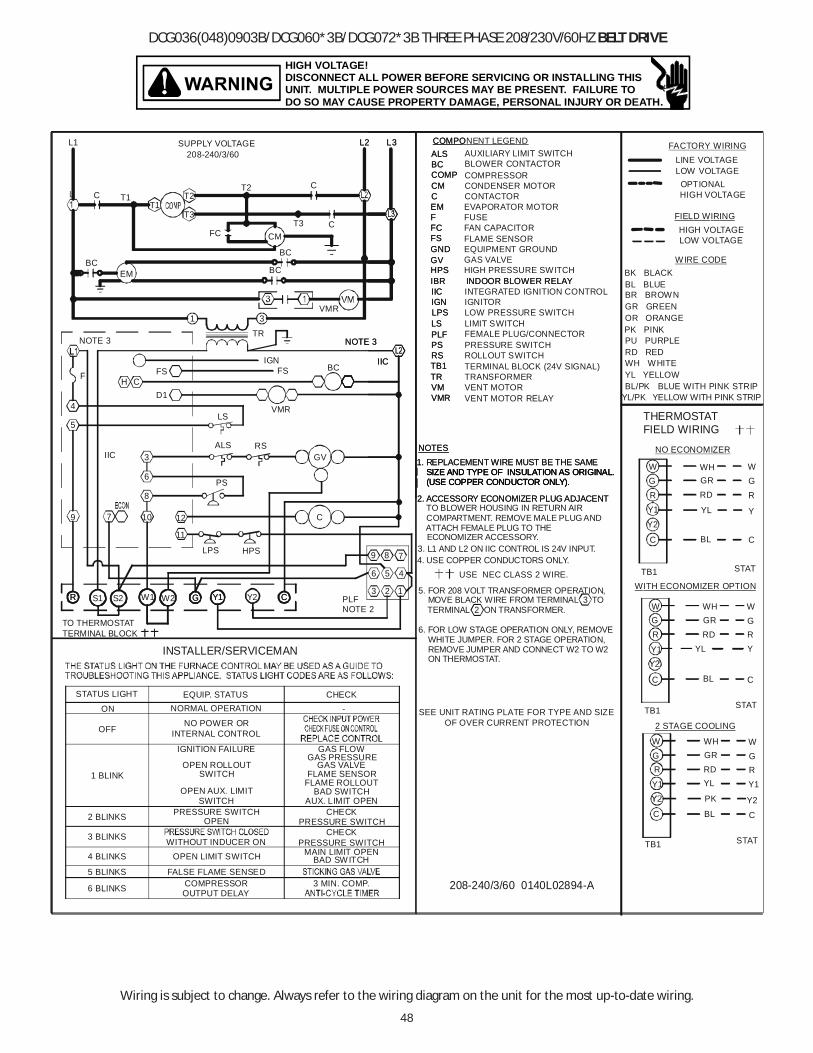
48
Wiring is subject to change. Always refer to the wiring diagram on the unit for the most up-to-date wiring.
HIGH VOLTAGE!DISCONNECT ALL POWER BEFORE SERVICING OR INSTALLING THISUNIT. MULTIPLE POWER SOURCES MAY BE PRESENT. FAILURE TODO SO MAY CAUSE PROPERTY DAMAGE, PERSONAL INJURY OR DEATH.
DCG036(048)0903B/DCG060*3B/DCG072*3B THREE PHASE 208/230V/60HZ BELT DRIVE
INSTALLER/SERVICEMAN
FALSE FLAME SENSED
OPEN LIMIT SWITCHWITHOUT INDUCER ON
PRESSURE SWITCH
NORMAL OPERATION
3 BLINKS
6 BLINKS
4 BLINKS
5 BLINKS
OUTPUT DELAYCOMPRESSOR
OFF
ON
1 BLINK
2 BLINKS
STATUS LIGHT
OPEN AUX. LIMIT
IGNITION FAILURE
OPEN ROLLOUT
SWITCH
OPEN
SWITCH
NO POWER ORINTERNAL CONTROL
EQUIP. STATUS
CHECK
MAIN LIMIT OPENBAD SW ITCH
3 MIN. COMP.
PRESSURE SWITCH
GAS PRESSURE
FLAME ROLLOUT
AUX. LIMIT OPEN
FLAME SENSOR
BAD SWITCH
GAS VALVE
GAS FLOW
PRESSURE SWITCHCHECK
-
CHECK
TRANSFORMERTR
ALS
COMP
COMPONENT LEGEND
COMPRESSOR
EM
IICIGN
GNDFS
GV
C
F FUSEFC
EVAPORATOR MOTOR
FLAME SENSOREQUIPMENT GROUND
IGNITOR
GAS VALVE
CONTACTOR
FAN CAPACITOR
RSTB1
PLFPS
VMVMR
ROLLOUT SWITCHTERMINAL BLOCK (24V SIGNAL)
PRESSURE SWITCH
VENT MOTORVENT MOTOR RELAY
LIMIT SWITCHLS
CONDENSER MOTORCM
INTEGRATED IGNITION CONTROL
FEMALE PLUG/CONNECTOR
AUXILIARY LIMIT SWITCH
IBR INDOOR BLOWER RELAY
BC BLOWER CONTACTOR
BC
L2 L3
CCM
T3
C
FC
208-240/3/60
T2
T3
T2T1
T1
L1
C
SUPPLY VOLTAGE
3VMR
BCIIC
VMR
FSIGN
NOTE 3
C
RSGV
3
6
PLF2
5
NOTE 2
1
EM
LS
H CD1
FSF
5
4
NOTE 3
ALS
PS
10
3
6
8
12
11
9
IIC
7
TR
1
4
208-240/3/60 0140L02894-A
LPS HPS
LPS LOW PRESSURE SWITCH
HPS HIGH PRESSURE SWITCH
BC
BC
3. L1 AND L2 ON IIC CONTROL IS 24V INPUT.
USE NEC CLASS 2 WIRE.
2. ACCESSORY ECONOMIZER PLUG ADJACENT TO BLOWER HOUSING IN RETURN AIR COMPARTMENT. REMOVE MALE PLUG AND ATTACH FEMALE PLUG TO THE ECONOMIZER ACCESSORY.
1. REPLACEMENT WIRE MUST BE THE SAME SIZE AND TYPE OF INSULATION AS ORIGINAL. (USE COPPER CONDUCTOR ONLY).
NOTES
LOW VOLTAGE
LINE VOLTAGE
FIELD WIRING
LOW VOLTAGE OPTIONAL HIGH VOLTAGE
FACTORY WIRING
HIGH VOLTAGE
BL
RD
Y1
YL
W
BL
GR
W
NO ECONOMIZER
G
YL
RD
Y2
Y1
PK
WH
W
R RD
WHGR
C
RYL
GR
Y1
GWH
WITH ECONOMIZER OPTION
C
GR
THERMOSTATFIELD WIRING
BL
C
2 STAGE COOLING
TB1
GR
W
Y
C
TB1
TB1
Y
W
RG
C
W
Y2
GR
C
Y1
STAT
STAT
STAT
BL/PK BLUE WITH PINK STRIPYL/PK YELLOW WITH PINK STRIP
GR GREEN
WIRE CODE
BL BLUE
PU PURPLEPK PINK
WH WHITE
BK BLACK
RD RED
BR BROWN
OR ORANGE
YL YELLOW
SEE UNIT RATING PLATE FOR TYPE AND SIZEOF OVER CURRENT PROTECTION
4. USE COPPER CONDUCTORS ONLY.
6. FOR LOW STAGE OPERATION ONLY, REMOVE WHITE JUMPER. FOR 2 STAGE OPERATION, REMOVE JUMPER AND CONNECT W2 TO W2 ON THERMOSTAT.
5. FOR 208 VOLT TRANSFORMER OPERATION, MOVE BLACK WIRE FROM TERMINAL 3 TO TERMINAL 2 ON TRANSFORMER.
9 8 7
GR Y2Y1 CGR W1 Y1 CW2S1 S2
TO THERMOSTATTERMINAL BLOCK
TR
ALS
COMP
COMPO
EM
IICIGN
GNDFS
GV
C
FFC
RSTB1
PLFPS
VMVMR
LS
CM
IBR INDOOR BLOWER RELAY
BC
L2 L3
IIC
NOTE 3
LPS
HPS
2. ACCESSORY ECONOMIZER PLUG ADJACENT
1. REPLACEMENT WIRE MUST BE THE SAME SIZE AND TYPE OF INSULATION AS ORIGINAL. SIZE AND TYPE OF INSULATION AS ORIGINAL. (USE COPPER CONDUCTOR ONLY). (USE COPPER CONDUCTOR ONLY).
NOTES

49
Wiring is subject to change. Always refer to the wiring diagram on the unit for the most up-to-date wiring.
HIGH VOLTAGE!DISCONNECT ALL POWER BEFORE SERVICING OR INSTALLING THISUNIT. MULTIPLE POWER SOURCES MAY BE PRESENT. FAILURE TODO SO MAY CAUSE PROPERTY DAMAGE, PERSONAL INJURY OR DEATH.
DCG0360454B* THREE PHASE 460V/60HZ BELT DRIVE
BK
OR
CF
BL
NOTE 3SEE
GR
WH
W1
RD
R
BL
C Y1S2 G
TO THERMOSTAT
575
575/3/60460/3/60
SEE NOTE 4
POWER SUPPLY
GR
YL/PK
BL/PK
OR
WH
BKOR
L3L2
L1
LPS
HPS
OR
RD
BK
BC
C
T3
T1T2
PK
RD
BR
BR RDFC
RD
OR
VM
BK
IGN
FS
NOTE 3SEE
YL
ORBK
460/575TR240
C460
BLBL
TR
24V
BL
VMR
3
1
2
WHRD
EM
OR
BK
RD
OR
GR
GV
GAS VALVE(ALT.) HONEYWELL
BL
BL
GV
GAS VALVEW. R.
PU
PU
MV
MV BL
BL
BL GR
ALS
RS
YL
PLFNOTE 2
PS
PU YL
PU
YLYL
BL
RD
YL
BRWH
RDRD
RD
PUBL
GR
WH
LSRD
RD
BKBR
CM
COMP
PU
BK
BK OR
RD
BL
BLL2L1 C
RD
BK
YL
PUBK
T2T1
IIC
YL
GR
BK
YL
L3
OR
RD
T3
GND
RD
5 841
9
7
623
GR
GR
YL
BL
BL BL
Y2
PU
S1
BR
BR
PK
PK
YL
BL
R
R
FOR SMOKE/FIREDETECTOR JUMPER
PU
RDFS
FOR SMOKE/FIREDETECTOR JUMPER
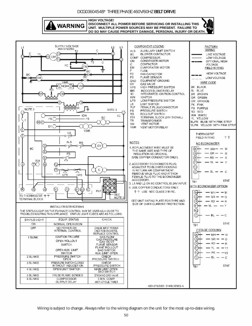
50
Wiring is subject to change. Always refer to the wiring diagram on the unit for the most up-to-date wiring.
HIGH VOLTAGE!DISCONNECT ALL POWER BEFORE SERVICING OR INSTALLING THISUNIT. MULTIPLE POWER SOURCES MAY BE PRESENT. FAILURE TODO SO MAY CAUSE PROPERTY DAMAGE, PERSONAL INJURY OR DEATH.
DCG0360454B* THREE PHASE 460V/60HZ BELT DRIVE
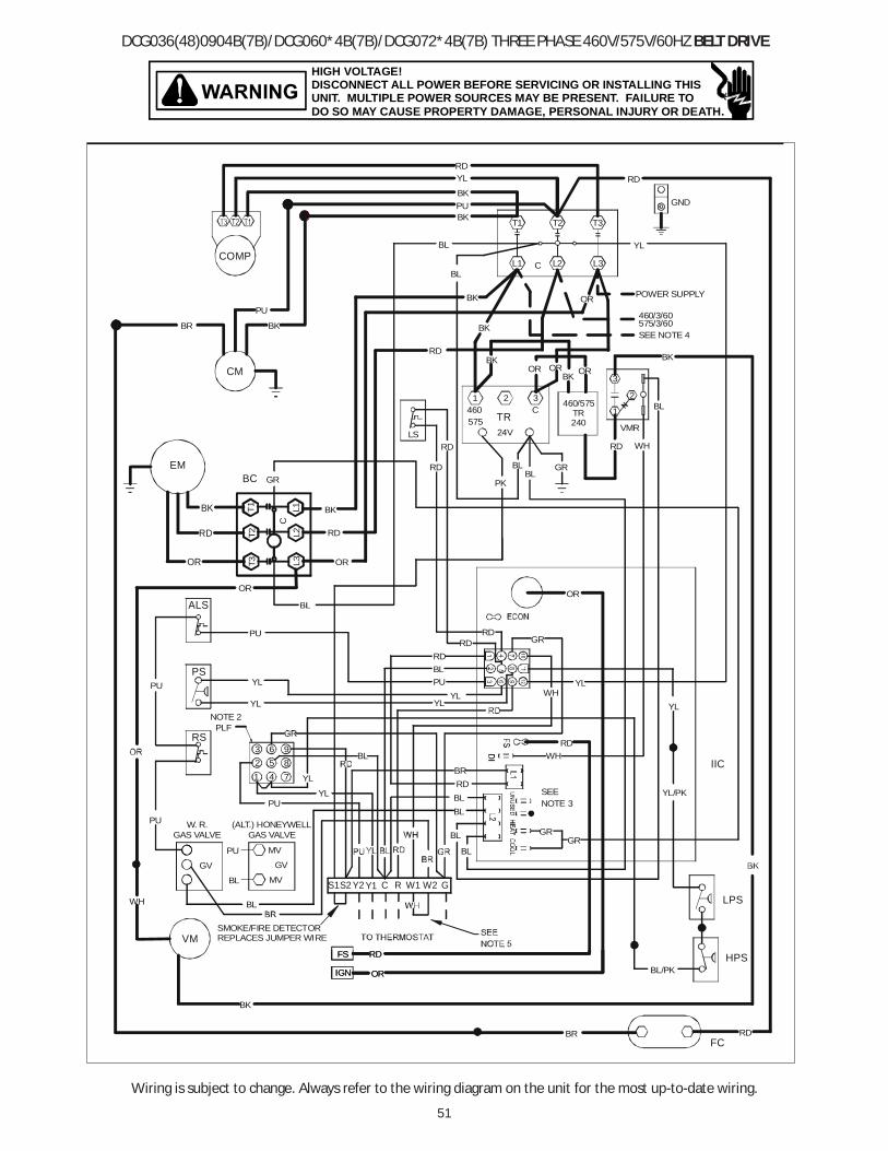
51
Wiring is subject to change. Always refer to the wiring diagram on the unit for the most up-to-date wiring.
HIGH VOLTAGE!DISCONNECT ALL POWER BEFORE SERVICING OR INSTALLING THISUNIT. MULTIPLE POWER SOURCES MAY BE PRESENT. FAILURE TODO SO MAY CAUSE PROPERTY DAMAGE, PERSONAL INJURY OR DEATH.
DCG036(48)0904B(7B)/DCG060*4B(7B)/DCG072*4B(7B) THREE PHASE 460V/575V/60HZ BELT DRIVE
FS
IGN
BK
VM
OR
RD
FCRDBR
SMOKE/FIRE DETECTORREPLACES JUMPER WIRE
HPSBL/PK
GND
T3
RD
OR
L3
YL
BK
GR
YL
IIC
T1 T2BKPU
YL
BK
RD
CL1 L2BL
BL
RD
ORBK
BK
PU
COMP
CM
BR BK
RD
RDLS
WH
GR
BLPU
RDRD
RD
WH
BR
YL
RD
BL
YL
YL
BL
YL
PU
YLPUPS
541
2
NOTE 2PLF
63
YL
RS
ALS
GRBL
BL
BL
YL
MV
MV
PU
PU W. R.GAS VALVE
GV
BL
BL
(ALT.) HONEYWELLGAS VALVE
GV
GR
OR
RD
BK
OR
EM
RD WH
2
1
3
VMR
BL
24V
TR
BLBL
1460
2 3C
460/575TR240
BK OR
PUSEENOTE 3
RD
PK
T2T1
T3
C
BC
BK
RD
OR
LPS
L1L2
L3
ORBK
WH
OR
YL/PK
GR
POWER SUPPLY
SEE NOTE 4
460/3/60575/3/60
575
87
9
Y2 Y1S1S2 RC W1 GW2
FS
IGN OR
RD

52
Wiring is subject to change. Always refer to the wiring diagram on the unit for the most up-to-date wiring.
HIGH VOLTAGE!DISCONNECT ALL POWER BEFORE SERVICING OR INSTALLING THISUNIT. MULTIPLE POWER SOURCES MAY BE PRESENT. FAILURE TODO SO MAY CAUSE PROPERTY DAMAGE, PERSONAL INJURY OR DEATH.
Wiring is subject to change. Always refer to the wiring diagram on the unit for the most up-to-date wiring.
3. L1 AND L2 ON IIC CONTROL IS 24V INPUT.
USE NEC CLASS 2 WIRE.4. USE COPPER CONDUCTORS ONLY.
2. ACCESSORY ECONOMIZER PLUG ADJACENT TO BLOWER HOUSING IN RETURN AIR COMPARTMENT. REMOVE MALE PLUG AND ATTACH FEMALE PLUG TO THE ECONOMIZER ACCESSORY.
1. REPLACEMENT WIRE MUST BE THE SAME SIZE AND TYPE OF INSULATION AS ORIGINAL. (USE COPPER CONDUCTOR ONLY).
INSTALLER/SERVICEMAN
FALSE FLAMESENSED
OPEN LIMIT SWITCHWITHOUT INDUCER ON
PRESSURE SWITCH
NORMAL OPERATION
INTERNAL CONTROL
3 BLINKS
6 BLINKS
4 BLINKS5 BLINKS
OUTPUT DELAYCOMPRESSOR
OFF
ON
1 BLINK
2 BLINKS
STATUS LIGHT
OPEN AUX. LIMIT
IGNITION FAILURE
OPEN ROLLOUT
SWITCH
OPEN
SWITCH
NO POWER OR
EQUIP. STATUS
CHECK
MAIN LIMIT OPENBAD SWITCH
3 MIN. COMP.
PRESSURE SWITCH
GAS PRESSURE
FLAME ROLLOUT
AUX. LIMIT OPEN
FLAME SENSOR
BAD SWITCH
GAS VALVE
GAS FLOW
PRESSURE SWITCHCHECK
-
CHECK
NOTES
TRANSFORMERTR
LOW VOLTAGE
FACTORY WIRING LINE VOLTAGE
LOW VOLTAGE
FIELD WIRING HIGH VOLTAGE
OPTIONAL HIGH VOLTAGE
ALS
COMP
COMPONENT LEGEND
COMPRESSOR
EM
IICIGN
GNDFS
GV
C
F FUSEFC
EVAPORATOR MOTOR
FLAME SENSOREQUIPMENT GROUND
IGNITOR
GAS VALVE
CONTACTOR
FAN CAPACITOR
RSTB1
PLFPS
VMVMR
ROLLOUT SWITCHTERMINAL BLOCK (24V SIGNAL)
PRESSURE SWITCH
VENT MOTORVENT MOTOR RELAY
LIMIT SWITCHLS
CONDENSER MOTORCM
INTEGRATED IGNITION CONTROL
FEMALE PLUG/CONNECTOR
AUXILLARY LIMIT SWITCH
IBR INDOOR BLOWER RELAY
BC BLOWER CONTACTOR
BC
L2 L3
CCM
T3
C
FC
T2
T3
T2T1
T1
L1
C
1
3
VMR
BC IIC
VMR
FSIGN
NOTE 3
C
RSGV
3
6
PLF 2
5
NOTE 2
1
EM
VM
LS
H CD1
FSF
5
4
NOTE 3
ALS
PS
10
3
6
8
12
11
9
IIC
7
TR
1
4
460-575/3/60 0140L02895-A
LPS HPS
LPS LOW PRESSURE SWITCH
HPS HIGH PRESSURE SWITCH
BC
BC
ORBKRD
BL
RDY1
YL
W
BL
GR
W
NO ECONOMIZER
G
YL
RD
Y2
Y1
PK
WH
W
R RD
WHGR
C
RYL
GR
Y1
GWH
WITH ECONOMIZER OPTION
C
GR
THERMOSTATFIELD WIRING
BL
C
2 STAGE COOLING
TB1
GR
W
Y
C
TB1
TB1
Y
W
RG
C
W
Y2
GR
C
Y1
STAT
STAT
STAT
BL/PK BLUE WITH PINK STRIPYL/PK YELLOW WITH PINK STRIP
GR GREEN
WIRE CODE
BL BLUE
PU PURPLEPK PINK
WH WHITE
BK BLACK
RD RED
BR BROWN
OR ORANGE
YL YELLOW
5. FOR LOW STAGE OPERATION ONLY, REMOVE WHITE JUMPER. FOR 2 STAGE OPERATION, REMOVE JUMPER AND CONNECT W2 TO W2 ON THERMOSTAT.TO THERMOSTAT
TERMINAL BLOCK
GR Y1 CGR W1 Y2Y1 CW2S1 S2

53
THIS PAGE LEFT INTENTIONALLY BLANK

54
THIS PAGE LEFT INTENTIONALLY BLANK

55
Start-up Checklist*Store in job file
Pre Start-Up(Check each item as completed)
Verify all packaging material has been removed.
Remove all shipping brackets per installation instructions.
Verify the job site voltage agrees with the unit serial plate.
Verify condensate connection is installed per installation instructions.
Verify proper clearance around the unit for safety, service, maintenance and proper unit operation.
Verify proper weatherproofing of all ductwork, roof curbs and electrical connections.
Check that the flue screen is in place.
Check gas piping for leaks.
Verify gas pressure to the unit is within the range specified on the serial plate.
Check to ensure that all fans, pulleys and wheels are secure.
Check for proper belt tension and alignment per installation instructions.
Check refrigerant piping for rubbing and leaks. Repair if necessary.
Check unit wiring to ensure it is not in contact with refrigerant piping or sharp metal edges.
Check all electrical connections and terminals. Tighten as needed.
Verify that the crankcase heaters have been energized for 24 hours.
Verify the scroll compressor(s) are rotating in the right direction.
Verify all accessories are installed and operating correctly.
Check filters and replace if necessary.
Verify the installation of the thermostat.
9/2014
Date: ___________________________________
Model Number: ___________________________________
Serial Number: ___________________________________
Technician: ___________________________________
Location: __________________________________________
__________________________________________
__________________________________________
Unit #: __________________________________________
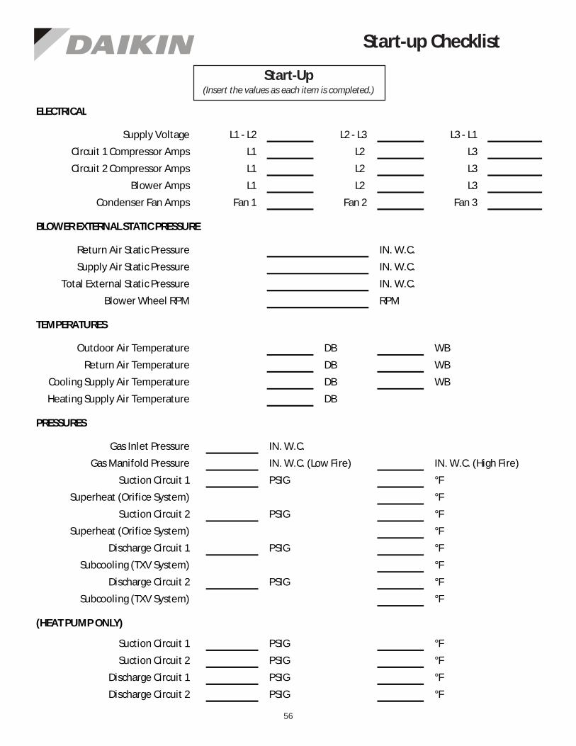
56
Start-up Checklist
L1 - L2 L2 - L3 L3 - L1
L1 L2 L3
L1 L2 L3
L1 L2 L3
Fan 1 Fan 2 Fan 3
IN. W.C.
IN. W.C.
IN. W.C.
RPM
DB WB
DB WB
DB WB
DB
IN. W.C.
IN. W.C. (Low Fire) IN. W.C. (High Fire)
PSIG °F
°F
PSIG °F
°F
PSIG °F
°F
PSIG °F
°F
PSIG °F
PSIG °F
PSIG °F
PSIG °F
BLOWER EXTERNAL STATIC PRESSURE
Return Air Static Pressure
Supply Air Static Pressure
Supply Voltage
Circuit 1 Compressor Amps
Circuit 2 Compressor Amps
Blower Amps
Condenser Fan Amps
ELECTRICAL
Total External Static Pressure
Blower Wheel RPM
TEMPERATURES
Outdoor Air Temperature
Return Air Temperature
Cooling Supply Air Temperature
Discharge Circuit 1
Heating Supply Air Temperature
PRESSURES
Gas Inlet Pressure
Gas Manifold Pressure
Suction Circuit 1
Suction Circuit 2
Discharge Circuit 2
Superheat (Orifice System)
Superheat (Orifice System)
Subcooling (TXV System)
Subcooling (TXV System)
Discharge Circuit 1
Discharge Circuit 2
(HEAT PUMP ONLY)
Suction Circuit 1
Suction Circuit 2
Start-Up(Insert the values as each item is completed.)
Related Documents