INSTALLATION INSTRUCTION PEM1188ENG 2013-05 ENGLISH HEAT SHRINK TRANSITION JOINTS HJT11.24 SBO CPEEL CPEEL CPEEL CPEEPL CPEEPL CPEEPL

Welcome message from author
This document is posted to help you gain knowledge. Please leave a comment to let me know what you think about it! Share it to your friends and learn new things together.
Transcript

INSTALLATION INSTRUCTION PEM1188ENG 2013-05
ENGLISH
HEAT SHRINK TRANSITION JOINTSHJT11.24
SB
O
CPEEL
CPEEL
CPEELCPEEPL
CPEEPL
CPEEPL

2/16 HJT11.24 PEM1188ENG 2013-05
GENERAL INFORMATION- Check that the kit is suitable for the cable type.
- Check the materials listed in the bill of materials for completeness.
- Read the installation instructions carefully before starting the installation.
- Install carefully and make sure the materials are clean during the installation.
- Clean the working place after the installation.
GENERAL INSTRUCTIONS FOR HEAT SHRINKING- Please note that in some working places a hot work permit is needed.
- Use a propane burner with a flame length of approx. 20-30 cm. Do not use too large or sharp flame.
- Move the flame all around the cable on the shrinking direction. Move the flame continuously to avoid overheat-
ing.
- Make sure that the ventilation is good and there are no flammable materials around.
- Clean the cable surfaces before shrinking.
- When shrinking, always follow the installation instructions and the relevant sequence to avoid trapped air.
- Check that the tube has shrunk evenly around the cable before you continue shrinking.
- If the tube turns around at the end of shrinking, straighten the tube by directing the flame inside the tube from
the opposite direction.
- After shrinking the tubes should be smooth and even following the shape inside.
LEGAL NOTICE- The product must be installed only by a competent person with sufficient training in installation practices and
with sufficient knowledge of good safety and installation practices in respect of electrical equipment. If local leg-
islation contains provisions in respect of such training or sufficient knowledge in respect of installation of electri-
cal equipment such provisions shall be fulfilled by the said person.
- Ensto accepts no liability concerning claims resulting from misuse, incorrect installation or ignored national safety
regulations or other national provisions.
- WARNING: Failure to follow the installation instructions may result in damage to the product and serious or fatal
injury.

PEM1188ENG 2013-05 HJT11.24 3/16
Reference line
Surplus part
Surplus part
400
1. Overlap the cables for approximately 1,5 m. Mark the cables in the middle of the overlap (reference line). Cut the paper insulated cable end from the marked reference line. To ensure the shield wires are long enough, cut the single core XLPE insulated cables 400 mm away from the reference line mark.
ARMOURED PAPER INSULATED CABLE
Outer covering
Armour
Cores
50
600
2. Cut and remove the outer covering up to 600 mm. Cut and remove the armour up to 50 mm from the outer covering or sheath. Cut and remove the possible inner covering or sheath.
Armour Roughen
Lead or aluminium sheath
250
3. Clean the outer covering up to at least 0,5 m distance. Spread the cores. Clean the armour and the lead or aluminium sheaths with a suitable solvent. Roughen the outer covering for 100 mm length and the armour for its length. Roughen the lead or aluminium sheaths for the distance of 250 mm with grinding paper.

4/16 HJT11.24 PEM1188ENG 2013-05
Outer covering
Tinned copper tape
50 20
4. Wrap two layers of tinned copper tape with 50 % overlap on the armour continuing 20 mm on the lead or aluminium sheaths.
Outer covering
Tinned copper tape
Copper wire
1060
5. Use tinned copper wire to fix the tinned copper tape on the armour at 10 mm and on the lead or alu-minium sheaths at 60 mm distance from the outer covering edge.
Sealing mastic PA22
Outer covering or sheath
50
6. Wrap sealing mastic PA22 on the armour and continue to cover 50 mm of the outer covering.
PEM1188ENG 2013-05 HJT11.24 5/16
SBO
Sealing breakout SBO
Shrinking sequence
7. Push the sealing breakout SBO into the crutch as far as possible. Shrink the breakout starting from the middle.
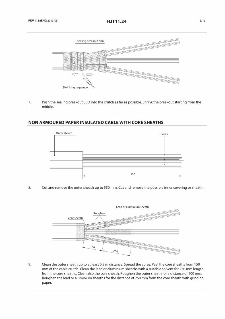
NON ARMOURED PAPER INSULATED CABLE WITH CORE SHEATHS
Outer sheath Cores
550
8. Cut and remove the outer sheath up to 550 mm. Cut and remove the possible inner covering or sheath.
Core sheathRoughen
Lead or aluminium sheath
150250
9. Clean the outer sheath up to at least 0.5 m distance. Spread the cores. Peel the core sheaths from 150 mm of the cable crutch. Clean the lead or aluminium sheaths with a suitable solvent for 250 mm length from the core sheaths. Clean also the core sheath. Roughen the outer sheath for a distance of 100 mm. Roughen the lead or aluminium sheaths for the distance of 250 mm from the core sheath with grinding paper.

6/16 HJT11.24 PEM1188ENG 2013-05
Outer sheath
Sealing mastic PA22
50
10. Wrap sealing mastic PA22 to cover 50 mm of the outer sheath.
SBO
Sealing breakout SBO
Shrinking sequence
11. Push the sealing breakout SBO into the crutch as far as possible. Shrink the breakout starting from the middle.
PAPER INSULATED CABLE (ALL TYPES)
CPEELSBO
CPEEL
CPEEL
Breakout �nger Sealing tube CPEEL
Shrinking sequence
12. Place the sealing tubes on the cores and push them on the breakout fingers up to about 20 mm from the crutch. Shrink the tubes one by one starting from the breakout end.

PEM1188ENG 2013-05 HJT11.24 7/16
CPEEL
Lead or aluminium sheath
Semiconductive paper
Paper insulation
10
A
13. Cut and remove the lead or aluminium sheath according to A measure in table 1. Remove the semicon-ductive paper leaving 10 mm at the lead or aluminium sheath edge. Remove the first layer of the paper insulation up to the semiconductive paper edge.
TABLE 1.
Kit Um kV Conductor size mm² Lead or aluminium sheath removal A mm
HJT11.2402 24 50-95 190
HJT11.2403 24 95-240 190
HJT11.2404 24 185-300 210
CPEEL
Stress control tape SSCTA85
15 15
14. Wrap one layer of stress control tape SSCTA85 on the edge of the lead or aluminium sheath. Cover 15 mm of the lead or aluminium sheath and continue 15 mm to the insulation side so that the semiconduc-tive paper remains under the taping. The tape must be applied with 50 % overlap and by stretching it to half of its original width.
CPEEL
STT
Shrinking sequenceTransparent tube
Lead or aluminium sheath5
15. Place the transparent tube on core so that it covers the stress control tape area and continues 5 mm on the lead or aluminium sheath. Shrink the tube starting from the lead or aluminium sheath end.

8/16 HJT11.24 PEM1188ENG 2013-05
PVC tape
Conductor
Half connector lenght +5
16. Cut the transparent tube and remove half of the bolt connector length + 5 mm from the insulation of the cable. If you use compression connectors, remove the insulation following the connector manufac-turer’s instructions. Be careful not to nick the conductor when removing the last paper layers. Clean the conductors and wrap some layers of PVC tape on them.
CPEEL STT
Semiconductive tape SSETA46
5
17. Wrap one layer of semiconductive tape SSE TA46 on the transparent tube. Cover the stress control taped area and continue 5 mm across the transparent tube edge on the lead or aluminium sheath. The tape must be applied with 50 % overlap and by stretching it to half of its original width
ONLY SINGLE CORE XLPE INSULATED CABLE WITH WIRE SHIELD
Wire shield Roughen Outer sheath
B+400 100
18. Cut and remove the outer sheath for B + 400 mm. Roughen around 100 mm length of the outer sheath. Clean the sheath up to at least 1.5 m distance to avoid tube inner surfaces to become dirty.

PEM1188ENG 2013-05 HJT11.24 9/16
Semiconductive layer Shield wires PVC tape
B
19. Cut the core to the B measure in table 2. Fold the shield wires on the outer sheath and fix them with some PVC tape.
TABLE 2.
Kit Um kV Conductor size mm² Core length B mm
HJT11.2402 24 50-95 250
HJT11.2403 24 95-240 250
HJT11.2404 24 185-300 270
80
Insulation Semiconductive layer
20. Remove the semiconductive layer leaving 80 mm measured from the outer sheath. Use a suitable tool. If necessary, remove any remaining of the semiconductive layer with a piece of glass. Use the grinding paper included in the kit to smooth the insulation.
Conductor Insulation
Half connector + 5 mm
21. Remove half of the bolt connector length + 5 mm from the insulation of the cable. If you use compres-sion connectors, remove the insulation following the connector manufacturer’s instructions. Be careful not to nick the conductor. Clean the conductor and wrap a couple layers of PVC tape on the end of the conductor.
10/16 HJT11.24 PEM1188ENG 2013-05
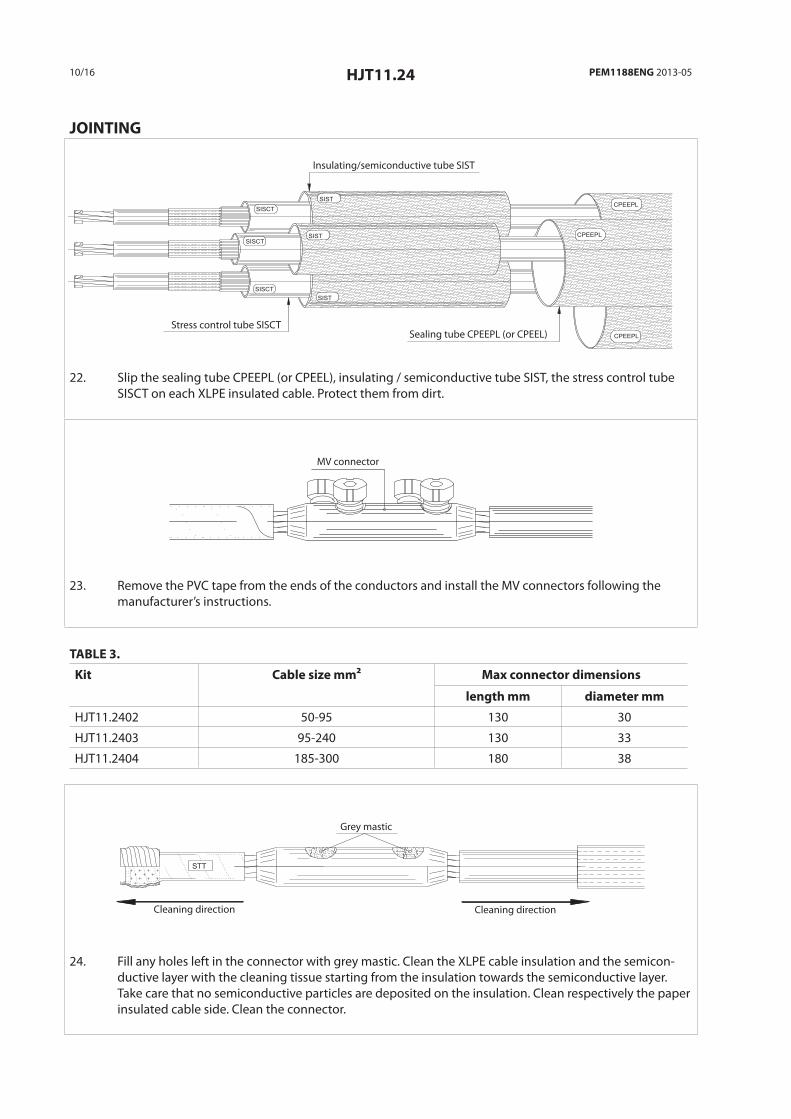
JOINTING
SISCT
SISCT
SIST
SIST
SISCTSIST
CPEEPL
CPEEPL
CPEEPL
Insulating/semiconductive tube SIST
Stress control tube SISCTSealing tube CPEEPL (or CPEEL)
22. Slip the sealing tube CPEEPL (or CPEEL), insulating / semiconductive tube SIST, the stress control tube SISCT on each XLPE insulated cable. Protect them from dirt.
MV connector
23. Remove the PVC tape from the ends of the conductors and install the MV connectors following the manufacturer’s instructions.
TABLE 3.
Kit Cable size mm² Max connector dimensions
length mm diameter mm
HJT11.2402 50-95 130 30
HJT11.2403 95-240 130 33
HJT11.2404 185-300 180 38
STT
Grey mastic
Cleaning directionCleaning direction
24. Fill any holes left in the connector with grey mastic. Clean the XLPE cable insulation and the semicon-ductive layer with the cleaning tissue starting from the insulation towards the semiconductive layer. Take care that no semiconductive particles are deposited on the insulation. Clean respectively the paper insulated cable side. Clean the connector.

PEM1188ENG 2013-05 HJT11.24 11/16
Stress control tape SSCTA85
15 15
25. Fill the gap between the end of the connector and the insulation with stress control tape SSCTA85. Then wrap two layers of SS CTA85 to cover the connector covering 15 mm of the transparent tube on the other side and the insulation on the other. SS CTA85 must be applied with a 50 % overlap and by stretching it to half of its original width.
Stress control tape SSCTA85
20 10
26. Wrap two layers of stress control tape SSCTA85 on the semiconductive layer edge on the XLPE cable side. Wrap SSCTA for 10 mm on the semiconductive layer and for 20 mm on the insulation. Start from the semiconductive layer side. SSCTA85 must be applied with a 50 % overlap and by stretching it to half of its original width.
SISCT
Stress control tube SISCT
Shrinking sequence
27. Centre the stress control tube SISCT on the connector. Start shrinking the tube from the middle and move towards the ends. Clean the surface of the stress control tube after shrinking.
SISCT
Sealing mastic SSM83 Sealing mastic SSM83Stress control tube SISCT Shield wires
Semiconductive layer30
28. Wrap two layers of sealing tape SSM83 starting from the end of the stress control tube and continu-ing for 30 mm on the paper insulated core side. Wrap two layers of sealing tape SSM83 to fill the gap between the stress control tube and the cable outer sheath on the XLPE insulated cable side.

12/16 HJT11.24 PEM1188ENG 2013-05
SIST
SISCT
Insulating and semiconductive tube SIST Sealing tape SSM83
Shrinking sequence
29. Centre the insulating and semiconductive tube SIST on top of the stress control tube. Start shrinking it from the middle and move towards the ends.
SIST
Tinned copper tape
40
30. Wrap tinned copper tape on the joint starting to cover 40 mm of the lead or aluminium sheath, continue to cover the joint up to wire shield. Tinned copper tape must be applied with a 20 % overlap. Fix the end of the tape by knotting it.
Constant force spring Tinned copper tape Shield wires
31. Fold the shield wires on the joint and fix them with two rounds of constant force spring on the tinned copper tape on the lead or aluminium sheath. Fold the wires back on the constant force spring and cut them along the spring edge at the joint side. Wrap the rest of the spring on the wires.
CPEEL
Self bonding insulating tape SSITA42Roughen Roughen
100 100
Outer sheath
32. Wrap sone layers of self-bonding insulating tape SSITA42 on the constant force spring and the shield wires to smooth the sharp edges. Self bonding insulating tape must be wrapped by stretching it a bit. Wrap the tape to the direction, which tightens up the constant force spring. Cover also the open lead or aluminium sheath.
Roughen 100 mm of the CPEEL tube on the paper insulated cable side, and 100 mm of the XLPE insu-lated cable outer sheath with grinding paper.

PEM1188ENG 2013-05 HJT11.24 13/16
CPEELCPEEPL
Sealing tube CPEEPL (or CPEEL)
Shrinking sequence
33. Centre the CPEEPL (or CPEEL) sealing tube on the joint. Start to shrink the tube from middle and move towards the ends. The tube is properly shrunk when the adhesive starts to come out from the ends.
SB
O
CPEEL
CPEEL
CPEELCPEEPL
CPEEPL
CPEEPL
34. The joint is finished and ready to use, but let it cool down before loading it mechanically.

14/16 NOTES PEM1188ENG 2013-05

PEM1188ENG 2013-05 NOTES 15/16

ENSTO FINLAND OYENSIO MIETTISEN KATU 2, P.O.BOX 7706101 PORVOO, FINLAND TEL. +358 204 76 21FAX +358 204 762 [email protected]
WWW.ENSTO.COM
PEM
1188
ENG
/ Is
sue
2013
-05-
27
Related Documents