OMI-2T optical machine interface Installation guide H-5439-8510-05-A

Welcome message from author
This document is posted to help you gain knowledge. Please leave a comment to let me know what you think about it! Share it to your friends and learn new things together.
Transcript

OMI-2T optical machine interface
Installation guideH-5439-8510-05-A

Renishaw part no:
First issued:
Revised
H-5439-8510-05-A
01.2010
06.2016
© 2010 – 2016 Renishaw plc. All rights reserved.
This document may not be copied or reproduced in whole or in part, or transferred to any other media or language, by any means, without the prior written permission of Renishaw plc.
The publication of material within this document does not imply freedom from the patent rights of Renishaw plc.
i
Contents
Before you begin . . . . . . . . . . . . . . . . . . . . . . . . . . . . . . . . . . . . . . . . . . . . . . . . . . . . . . . . . . . . . 1 .1
Before you begin . . . . . . . . . . . . . . . . . . . . . . . . . . . . . . . . . . . . . . . . . . . . . . . . . . . . . . . . . . . . 1 .1
Disclaimer . . . . . . . . . . . . . . . . . . . . . . . . . . . . . . . . . . . . . . . . . . . . . . . . . . . . . . . . . . . . . . 1 .1
Trade marks . . . . . . . . . . . . . . . . . . . . . . . . . . . . . . . . . . . . . . . . . . . . . . . . . . . . . . . . . . . . . 1 .1
Warranty . . . . . . . . . . . . . . . . . . . . . . . . . . . . . . . . . . . . . . . . . . . . . . . . . . . . . . . . . . . . . . . . 1 .1
Changes to equipment . . . . . . . . . . . . . . . . . . . . . . . . . . . . . . . . . . . . . . . . . . . . . . . . . . . . . 1 .1
CNC machines . . . . . . . . . . . . . . . . . . . . . . . . . . . . . . . . . . . . . . . . . . . . . . . . . . . . . . . . . . . 1 .1
Care of the interface . . . . . . . . . . . . . . . . . . . . . . . . . . . . . . . . . . . . . . . . . . . . . . . . . . . . . . . 1 .1
Patents . . . . . . . . . . . . . . . . . . . . . . . . . . . . . . . . . . . . . . . . . . . . . . . . . . . . . . . . . . . . . . . . . 1 .2
EC declaration of conformity . . . . . . . . . . . . . . . . . . . . . . . . . . . . . . . . . . . . . . . . . . . . . . . . . . . 1 .3
WEEE directive . . . . . . . . . . . . . . . . . . . . . . . . . . . . . . . . . . . . . . . . . . . . . . . . . . . . . . . . . . . . . 1 .3
FCC information to user (USA only) . . . . . . . . . . . . . . . . . . . . . . . . . . . . . . . . . . . . . . . . . . . . . 1 .3
Safety . . . . . . . . . . . . . . . . . . . . . . . . . . . . . . . . . . . . . . . . . . . . . . . . . . . . . . . . . . . . . . . . . . . . 1 .4
OMI-2T basics . . . . . . . . . . . . . . . . . . . . . . . . . . . . . . . . . . . . . . . . . . . . . . . . . . . . . . . . . . . . . . . . 2 .1
Introduction . . . . . . . . . . . . . . . . . . . . . . . . . . . . . . . . . . . . . . . . . . . . . . . . . . . . . . . . . . . . . . . . 2 .1
Power supply . . . . . . . . . . . . . . . . . . . . . . . . . . . . . . . . . . . . . . . . . . . . . . . . . . . . . . . . . . . . 2 .1
Input voltage ripple . . . . . . . . . . . . . . . . . . . . . . . . . . . . . . . . . . . . . . . . . . . . . . . . . . . . . . . . 2 .1
OMI-2T visual diagnostics . . . . . . . . . . . . . . . . . . . . . . . . . . . . . . . . . . . . . . . . . . . . . . . . . . . . . 2 .2
Magnetic label . . . . . . . . . . . . . . . . . . . . . . . . . . . . . . . . . . . . . . . . . . . . . . . . . . . . . . . . . . . 2 .2
START SIGNAL LED (yellow) . . . . . . . . . . . . . . . . . . . . . . . . . . . . . . . . . . . . . . . . . . . . . . . . 2 .3
LOW BATTERY LED (red) . . . . . . . . . . . . . . . . . . . . . . . . . . . . . . . . . . . . . . . . . . . . . . . . . . 2 .3
PROBE STATUS LED (green, red) . . . . . . . . . . . . . . . . . . . . . . . . . . . . . . . . . . . . . . . . . . . . 2 .3
ERROR LED (red, blue, yellow, violet) . . . . . . . . . . . . . . . . . . . . . . . . . . . . . . . . . . . . . . . . . 2 .3
SIGNAL CONDITION LED (red, yellow, green) . . . . . . . . . . . . . . . . . . . . . . . . . . . . . . . . . . 2 .3
ACTIVE SYSTEM LEDs (green) . . . . . . . . . . . . . . . . . . . . . . . . . . . . . . . . . . . . . . . . . . . . . 2 .3
OMI-2T inputs . . . . . . . . . . . . . . . . . . . . . . . . . . . . . . . . . . . . . . . . . . . . . . . . . . . . . . . . . . . . . . 2 .3
OMI-2T outputs . . . . . . . . . . . . . . . . . . . . . . . . . . . . . . . . . . . . . . . . . . . . . . . . . . . . . . . . . . . . . 2 .4
OMI-2T output waveforms . . . . . . . . . . . . . . . . . . . . . . . . . . . . . . . . . . . . . . . . . . . . . . . . . . . . . 2 .5
Switches SW1 and SW2 . . . . . . . . . . . . . . . . . . . . . . . . . . . . . . . . . . . . . . . . . . . . . . . . . . . . . . 2 .6
Switch on / switch off . . . . . . . . . . . . . . . . . . . . . . . . . . . . . . . . . . . . . . . . . . . . . . . . . . . . . . 2 .7

OMI-2T installation guide
ii
Co
nte
nts
OMI-2T dimensions . . . . . . . . . . . . . . . . . . . . . . . . . . . . . . . . . . . . . . . . . . . . . . . . . . . . . . . . . . 2 .8
OMI-2T specification . . . . . . . . . . . . . . . . . . . . . . . . . . . . . . . . . . . . . . . . . . . . . . . . . . . . . . . . . 2 .9
System installation . . . . . . . . . . . . . . . . . . . . . . . . . . . . . . . . . . . . . . . . . . . . . . . . . . . . . . . . . . . 3 .1
Mounting bracket (optional) . . . . . . . . . . . . . . . . . . . . . . . . . . . . . . . . . . . . . . . . . . . . . . . . . . . . 3 .1
Wiring diagram (with output groupings shown) . . . . . . . . . . . . . . . . . . . . . . . . . . . . . . . . . . . . . 3 .2
OMI-2T cable . . . . . . . . . . . . . . . . . . . . . . . . . . . . . . . . . . . . . . . . . . . . . . . . . . . . . . . . . . . . . . . 3 .3
Cable sealing . . . . . . . . . . . . . . . . . . . . . . . . . . . . . . . . . . . . . . . . . . . . . . . . . . . . . . . . . . . . 3 .3
Fitting flexible conduit . . . . . . . . . . . . . . . . . . . . . . . . . . . . . . . . . . . . . . . . . . . . . . . . . . . . . . 3 .3
Screw torque values . . . . . . . . . . . . . . . . . . . . . . . . . . . . . . . . . . . . . . . . . . . . . . . . . . . . . . . . . 3 .4
Maintenance . . . . . . . . . . . . . . . . . . . . . . . . . . . . . . . . . . . . . . . . . . . . . . . . . . . . . . . . . . . . . . . . . 4 .1
Maintenance . . . . . . . . . . . . . . . . . . . . . . . . . . . . . . . . . . . . . . . . . . . . . . . . . . . . . . . . . . . . . . . 4 .1
Cleaning the interface . . . . . . . . . . . . . . . . . . . . . . . . . . . . . . . . . . . . . . . . . . . . . . . . . . . . . 4 .1
Removing the OMI-2T window . . . . . . . . . . . . . . . . . . . . . . . . . . . . . . . . . . . . . . . . . . . . . . . . . 4 .2
Fitting the OMI-2T window . . . . . . . . . . . . . . . . . . . . . . . . . . . . . . . . . . . . . . . . . . . . . . . . . . . . 4 .2
Fault-finding . . . . . . . . . . . . . . . . . . . . . . . . . . . . . . . . . . . . . . . . . . . . . . . . . . . . . . . . . . . . . . . . . 5 .1
Parts list . . . . . . . . . . . . . . . . . . . . . . . . . . . . . . . . . . . . . . . . . . . . . . . . . . . . . . . . . . . . . . . . . . . . . 6 .1

1.1
Before you begin
Disclaimer
RENISHAW HAS MADE CONSIDERABLE EFFORTS TO ENSURE THE CONTENT OF THIS DOCUMENT IS CORRECT AT THE DATE OF PUBLICATION BUT MAKES NO WARRANTIES OR REPRESENTATIONS REGARDING THE CONTENT . RENISHAW EXCLUDES LIABILITY, HOWSOEVER ARISING, FOR ANY INACCURACIES IN THIS DOCUMENT .
Trade marks
RENISHAW and the probe symbol used in the RENISHAW logo are registered trade marks of Renishaw plc in the United Kingdom and other countries . apply innovation and names and designations of other Renishaw products and technologies are trade marks of Renishaw plc or its subsidiaries .
All other brand names and product names used in this document are trade names, trade marks, or registered trade marks of their respective owners .
Warranty
Equipment requiring attention under warranty must be returned to your equipment supplier .
Unless otherwise specifically agreed in writing between you and Renishaw, if you purchased the equipment from a Renishaw company, the warranty provisions contained in Renishaw’s CONDITIONS OF SALE apply . You should consult these conditions in order to find out the details of your warranty, but in summary the main exclusions from the warranty are if the equipment has been:
• neglected, mishandled or inappropriately used; or
• modified or altered in any way except with the prior written agreement of Renishaw .
If you purchased the equipment from any other supplier, you should contact them to find out what repairs are covered by their warranty .
Changes to equipment
Renishaw reserves the right to change equipment specifications without notice .
CNC machines
CNC machine tools must always be operated by fully trained personnel in accordance with the manufacturer's instructions .
Care of the interface
Keep system components clean .
Before you begin

OMI-2T installation guide
1.2
Bef
ore
yo
u b
egin
Patents
Features of OMI-2T (and features of similar products) are the subject of one or more of the following patents and/or patent applications:
EP 0974208
EP 1503524
JP 4294101
US 6,839,563

1.3
Bef
ore
yo
u b
egin
CFCC information to user (USA only)
47 CFR Section 15.19
This device complies with part 15 of the FCC Rules . Operation is subject to the following two conditions:
1 . This device may not cause harmful interference, and
2 . This device must accept any interference received, including interference that may cause undesired operation .
47 CFR Section 15.21
The user is cautioned that any changes or modifications not expressly approved by Renishaw plc or authorised representative could void the user’s authority to operate the equipment .
47 CFR Section 15.105
This equipment has been tested and found to comply with the limits for a Class A digital device, pursuant to part 15 of the FCC Rules . These limits are designed to provide reasonable protection against harmful interference when the equipment is operated in a commercial environment . This equipment generates, uses, and can radiate radio frequency energy and, if not installed and used in accordance with the instruction manual, may cause harmful interference to radio communications . Operation of this equipment in a residential area is likely to cause harmful interference in which case the user will be required to correct the interference at his own expense .
EC declaration of conformity
Renishaw plc declares that the OMI-2T complies with the applicable standards and regulations .
Contact Renishaw plc or visit www .renishaw .com/omi-2t for the full EC declaration of conformity .
WEEE directive
The use of this symbol on Renishaw products and/or accompanying documentation indicates that the product should not be mixed with general household waste upon disposal . It is the responsibility of the end user to dispose of this product at a designated collection point for waste electrical and electronic equipment (WEEE) to enable reuse or recycling . Correct disposal of this product will help to save valuable resources and prevent potential negative effects on the environment . For more information, please contact your local waste disposal service or Renishaw distributor .

OMI-2T installation guide
1.4
Bef
ore
yo
u b
egin
Safety
Information to the user
In all applications involving the use of machine tools or CMMs, eye protection is recommended .
The OMI-2T has a glass window . Handle with care if broken to avoid injury .
Information to the machine supplier/ installer
It is the machine supplier's responsibility to ensure that the user is made aware of any hazards involved during operation, including those mentioned in Renishaw product literature, and to ensure that adequate guards and safety interlocks are provided .
Under certain circumstances, the probe signal may falsely indicate a probe seated condition . Do not rely on probe signals to halt the movement of the machine .
Information to the equipment installer
All Renishaw equipment is designed to comply with the relevant EC and FCC regulatory requirements . It is the responsibility of the equipment installer to ensure that the following guidelines are adhered to, in order for the product to function in accordance with these regulations:
• any interface MUST be installed in a position away from any potential sources of electrical noise, i .e . power transformers, servo drives etc;
• all 0 V/ground connections should be connected to the machine “star point” (the “star point” is a single point return for all equipment ground and screen cables) . This is very important, and failure to adhere to this can cause a potential difference between grounds;
• all screens must be connected as outlined in the user instructions;
• cables must not be routed alongside high-current sources, i .e . motor power supply cables etc, or be near high-speed data lines;
• cable lengths should always be kept to a minimum .
• the dc supply to this equipment must be derived from a source which is approved to IEC/BS/EN 60950-1 .
Equipment operation
If this equipment is used in a manner not specified by the manufacturer, the protection provided by the equipment may be impaired .
Optical safety
This product contains LEDs that emit both visible and invisible light .
OMI-2T is ranked Risk Group: Exempt (safe by design) .
The product was evaluated and classified using the following standard:
BS EN 62471:2008 The photobiological safety of lamps and lamp systems .
Renishaw recommends that you do not stare at or look directly into any LED device, irrespective of its risk classification .

2.1
Introduction
The OMI-2T is a combined optical receiver and machine interface which is designed to be mounted within the machine’s working envelope .
The OMI-2T operates using a ‘Modulated’ optical transmission mode and is compatible with machine probes that also operate in ‘Modulated’ mode .
Power supply
The OMI-2T can draw its supply from the CNC machine’s nominal 12 Vdc to 30 Vdc supply .
The maximum peak supply current is 160 mA when the OMI-2T is transmitting . The average supply current is 40 mA when the OMI-2T is receiving . The values quoted are for a 24 Vdc supply and assume all outputs are open circuit .
CAUTION: This equipment will only perform to specification if the power supply 0 V is connected to the machine ground (“star point”) .
Input voltage ripple
The input voltage ripple must not cause the voltage to fall below 12 V or rise above 30 V .
OMI-2T basics
OMI-2T installation guide
2.2
OM
I-2T
bas
ics
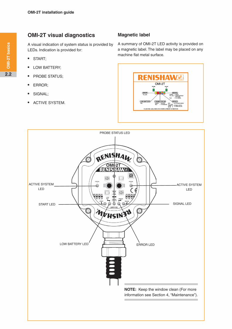
OMI-2T visual diagnostics
A visual indication of system status is provided by LEDs . Indication is provided for:
• START;
• LOW BATTERY;
• PROBE STATUS;
• ERROR;
• SIGNAL;
• ACTIVE SYSTEM .
Magnetic label
A summary of OMI-2T LED activity is provided on a magnetic label . The label may be placed on any machine flat metal surface .
ERROR LED
PROBE STATUS LED
LOW BATTERY LED
SIGNAL LEDSTART LED
NOTE: Keep the window clean (For more information see Section 4, “Maintenance”) .
ACTIVE SYSTEM
LED
ACTIVE SYSTEM
LED

2.3
OM
I-2T
bas
ics
START SIGNAL LED (yellow)
This LED will flash once when a machine control START signal is commanded .
LOW BATTERY LED (red)
The LED is lit when the activated probe battery voltage falls below a set level .
Replace the probe battery as soon as is practicable after this LED is lit .
PROBE STATUS LED (green, red)
This bicolour LED is lit when the OMI-2T is powered .
Green – Probe is seated .
Red – Probe is triggered or an error has occurred .
The change of colour of this LED will coincide with the probe status output devices changing state .
ERROR LED (red, blue, yellow, violet)
Indicates a transmission error condition, e .g . optical beam obstructed, probe out of optical range, probe switched off or battery dead .
Red – No transmission: The signal from the probe has either failed or has stopped .
Blue – Multiple probe detected: A second modulated signal is being received .
Yellow – Interference: Interference or a weak probe signal is being received .
Violet – Gauging: Interference or a weak probe signal has caused the trigger instant to be delayed .
NOTE: The indication of a blue, yellow or violet error condition resulting from the loss of a good probe signal will persist until the active system input (Probe 1 or Probe 2) is deactivated .
SIGNAL CONDITION LED (red, yellow, green)
This tricolour LED is lit when the OMI-2T is powered and indicates as follows:
Red – No communication: There is no signal from the probe .
Yellow – Interference: Either the signal received from the probe is too weak, or interference is present .
Green – Good communication: The condition of signal received from the probe is good .
ACTIVE SYSTEM LEDs (green)
The LEDs are lit green to show which system input (Probe 1 or Probe 2) is active . Providing the relevant probe is in range and operational, it will be active as long as the LED is lit .
Off when system input is inactive .

OMI-2T installation guide
2.4
OM
I-2T
bas
ics
OMI-2T inputs
There are two inputs:
• Probe 1 start
• Probe 2 start
Level 12 V to 30 V (10 mA @ 24 V) When the input is active, the probe is switched on .
The OMI-2T uses level machine inputs to define the active probe . When the respective input is active, the probe is switched on .
If both inputs are active the system will default to error .
OMI-2T outputs
There are four outputs:
• Probe status 1 (SSR)
• Probe status 2 (SSR)
• Error (SSR)
• Low battery (SSR)
All outputs can be inverted by using switches SW1 and SW2, (see “Switches SW1 and SW2” on page 2 .6) .
Probe status 1, Error, Low battery (SSR):
• ‘On’ resistance = 50 W max .
• Load voltage = 40 V max .
• Load current = 100 mA max .
Switching times (with 10 mA load)
• Open to closed = 100 µs max .
• Closed to open = 25 µs max .
Both of the probe status outputs indicate the status of the selected probe (only one probe can be selected at a time) . They are both individually configurable .
The Low Battery, Probe Status, and Error LEDs will start flashing red when an output overload has occurred . Probe status output will be triggered (SSR open) . If this occurs, turn off the power supply and remove the source of the problem . Turning on the power supply will reset the OMI-2T .
CAUTIONS:
Power supply voltageDo not exceed 30 V between: the black wire and the screen wire (green/yellow); the red wire and screen wire (green/yellow); or the red and black wires (power supply); as this could result in permanent damage to the OMI-2T and/or the customer power supply .
The use of in-line fuses at the machine cabinet end is recommended to provide protection for the OMI-2T and cable .
Screen connectionA good connection must be made to the machine ground (star point) .
Output
Ensure the output from the OMI-2T does not exceed the specified current ratings .
2.5
OM
I-2T
bas
ics
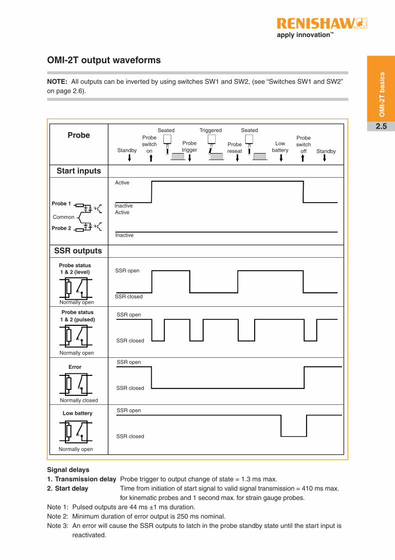
OMI-2T output waveforms
NOTE: All outputs can be inverted by using switches SW1 and SW2, (see “Switches SW1 and SW2” on page 2.6).
SSR outputs
Probe status 1 & 2 (level)
Probe status 1 & 2 (pulsed)
Normally open
Normally open
Probe switch
on
Seated
Probe trigger
Probe reseat
Triggered Seated
Low battery Standby
Probe switch
off
SSR open
SSR closed
Standby
Signal delays 1. Transmission delay Probe trigger to output change of state = 1.3 ms max. 2. Start delay Time from initiation of start signal to valid signal transmission = 410 ms max. for kinematic probes and 1 second max. for strain gauge probes. Note 1: Pulsed outputs are 44 ms ±1 ms duration.Note 2: Minimum duration of error output is 250 ms nominal.Note 3: An error will cause the SSR outputs to latch in the probe standby state until the start input is reactivated.
Error
Normally closed
Normally open
Low battery
Probe
Start inputs
Probe 1
Probe 2
Common
Active
Inactive
Inactive
Active
SSR open
SSR closed
SSR open
SSR closed
SSR open
SSR closed
OMI-2T installation guide
2.6
OM
I-2T
bas
ics
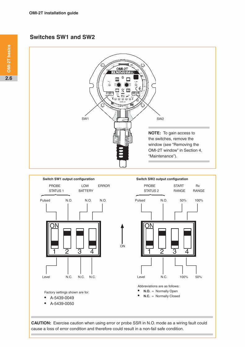
Switches SW1 and SW2
SW1 SW2
Factory settings shown are for:
• A-5439-0049• A-5439-0050
ON
CAUTION: Exercise caution when using error or probe SSR in N.O. mode as a wiring fault could cause a loss of error condition and therefore could result in a non-fail safe condition.
Switch SW1 output configuration Switch SW2 output configuration
Abbreviations are as follows:
• N.O. = Normally Open
• N.C. = Normally Closed
PROBE LOW ERROR
STATUS 1 BATTERY
Pulsed N.O. N.O. N.O.
Level N.C. N.C. N.C.
PROBE START Rx
STATUS 2 RANGE RANGE
Pulsed N.O. 50% 100%
Level N.C. 100% 50%
NOTE: To gain access to the switches, remove the window (see “Removing the OMI-2T window” in Section 4, “Maintenance”).

2.7
OM
I-2T
bas
ics
Switch on / switch off
Switch on / switch off method
The OMI-2T operates using only optical on / optical off as the switch on / switch off method.
Optical on / optical off is available with all Renishaw’s OMP range of spindle probes and the optical tool setter (OTS). Time out, spin on / spin off and shank on / shank off options are not compatible with the OMI-2T.
Start up times
In normal operation the start up time for modulated probes (as reported by the OMI-2T error signal) is 410 ms max. for kinematic probes. For strain gauge probes the start up time is 1 sec max.
The turn off time is 0 seconds.
Normal operation refers to when the on/off status of the probes is in synchronisation with the receiver on/off status. The active probe should correspond to the respective active system LED.
When changing from Probe 1 to Probe 2, or Probe 2 to Probe 1, allow 1 second between the cancelling of one machine start input and raising of the other start input, also allow 1 second when turning the probe off and back on again.
Synchronisation recovery
Under abnormal operating situations the system may lose synchronisation between the receiver and probes. An internal synchronisation recovery will be initiated when the next machine input is received.
The maximum time for system recovery from an abnormal operating situation is 3.5 seconds. Such a time delay could cause a machine alarm if controllers require ready signals within a time of less than 3.5 seconds.
NOTE: When used in conjunction with an OMP400 or OMP600, ensure the probe is set to the standard switch-on delay.
OMI-2T installation guide
2.8
OM
I-2T
bas
ics
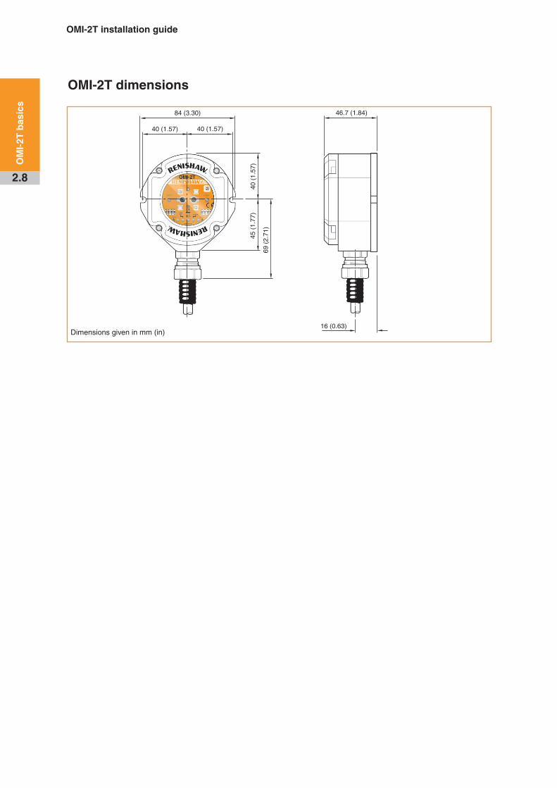
OMI-2T dimensions
Dimensions given in mm (in)
46 .7 (1 .84)
16 (0 .63)
84 (3 .30)
40 (1 .57) 40 (1 .57)
40 (
1 .57
)45
(1 .
77)
69 (
2 .71
)

2.9
OM
I-2T
bas
ics
OMI-2T specification
Principal application The OMI-2T processes signals from or standard probes, and converts them into machine outputs, which are then transmitted to the CNC control. The system allows two probes to be used with one interface.
Transmission type Infrared optical transmission (modulated)
Probes per system Two
Compatible probes OMP40-2, OMP40M, OLP40, OMP60, OMP60M, OMP400, OMP600 and OTS
Operating range Up to 6 m (19.7 ft)
Weight OMI-2T including 8 m (26.2 ft) of cable = 980 g (34.57 oz)OMI-2T including 15 m (49.2 ft) of cable = 1502 g (52.98 oz)
Supply voltage 12 Vdc to 30 Vdc (see “Wiring diagram” in Section 3, “System installation”)
Supply current Transmitting: 160 mA max. peak Receiving: 40 mA average Note: @24 Vdc, all outputs open circuit.
M-code inputs Level 10 V to 30 V (10 mA @ 24 V)
Output signals Probe Status 1, Probe Status 2, Low Battery, ErrorVoltage-free solid-state relay (SSR) outputs, configurable normally open or normally closed. Switching times (with 10 mA load), open to closed 100 µs max., closed to open 25 µs max.
Input / output protection Supply protected by resettable fuse. Outputs protected by over current protection circuit.
Cable (to machine control)
Specification Ø7.5 mm (0.29 in), 13-core screened cable, each core 18 × 0.1 mm
Length 8 m (26.2 ft), 15 m (49.2 ft)
Diagnostic LEDs Start, low battery, probe status, error, active system and signal condition.
Mounting Flush mounting or directional mounting with optional mounting bracket (available separately).
Environment IP rating IPX8 (EN/IEC 60529)
IK rating IK03 (EN/IEC 62262) [for glass window]
Storage temperature -25 °C to +70 °C (-13 °F to +158 °F)
Operating temperature +5 °C to +55 °C (+41 °F to +131 °F)

OMI-2T installation guide
2.10
OM
I-2T
bas
ics
This page is intentionally left blank .

3.1
System installation
Mounting bracket (optional)
Dimensions given in mm (in)
25
(0 .98)
25
(0 .98)
19 (
0 .75
)
38 (
1 .50
)
3 holes Ø6 .4 (0 .25) 3 grip protrusions
100 .5 (3 .95)
2 .0
(0 .0
8)
30
(1 .1
8)
25
(0 .9
8)
45
(1 .7
7)
45 (1 .77) 45°
90 (3 .54)
3 pairs of holes
Ø5 .3 (0 .20)
permit OMI-2T
mounting in
an alternative
orientation
2 .0
(0 .08)
NOTE: Install OMI-2T with cable exiting from lower side for good coolant run off .
OMI-2T installation guide
3.2
Sys
tem
in
stal
lati
on
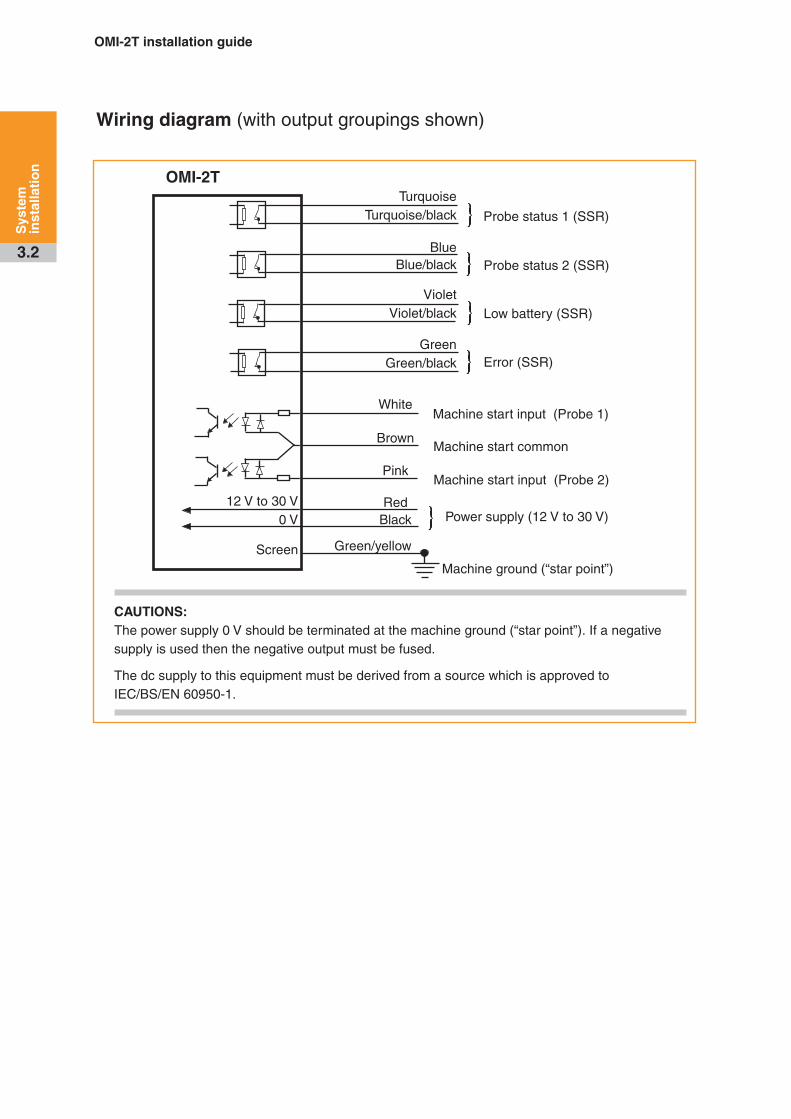
Wiring diagram (with output groupings shown)
OMI-2T
CAUTIONS: The power supply 0 V should be terminated at the machine ground (“star point”) . If a negative supply is used then the negative output must be fused .
The dc supply to this equipment must be derived from a source which is approved to IEC/BS/EN 60950-1 .
12 V to 30 V0 V
Screen
TurquoiseTurquoise/black
Blue Blue/black
Violet Violet/black
GreenGreen/black
White
Brown
Pink
RedBlack
Green/yellow
Machine ground (“star point”)
Power supply (12 V to 30 V)
Low battery (SSR)
Probe status 1 (SSR)
Probe status 2 (SSR)
Machine start input (Probe 1)
Error (SSR)
Machine start common
Machine start input (Probe 2)

3.3
Sys
tem
in
stal
lati
on
OMI-2T cable
Cable termination
A ferrule should be crimped onto each cable wire for a more positive connection at the terminal box .
Standard cable variants
The OMI-2T standard polyurethane cables are 8 m (26 ft) and 15 m (49 .2 ft) long .
Please contact Renishaw for other cable lengths .
Cable specification
Ø7 .5 mm (0 .29 in), 13-core screened cable, each core 18 x 0 .1 mm .
NOTE: Maximum length of the specified cable must not exceed 25 m (82 ft) .
Cable sealing
Coolant and dirt are prevented from entering the OMI-2T by the cable sealing gland . The OMI-2T cable can be protected against physical damage by fitting a flexible conduit if required .
A recommended flexible conduit is Anamet™ Sealtite HFX (5/16 in) polyurethane .
A conduit kit is available (see Section 6, “Parts list”) .
CAUTIONS: Failure to adequately protect the cable can result in system failure due to either cable damage or coolant ingress through cores into the OMI-2T . Failure due to inadequate cable protection will invalidate the warranty . When tightening or loosening nut B on the conduit, ensure that torque is only applied between A and B .
Fitting flexible conduit
Adaptor A
Conduit termination piece
Plastic olive
Nut B
Cable
Flexibleconduit
NOTE: Conduit bulkhead fittings require a clearance hole for an M16 thread .
1 . Slide nut B and the plastic olive onto the conduit .
2 . Screw the conduit termination piece into the end of the conduit .
3 . Fit the conduit to adaptor A and tighten nut B .
OMI-2T installation guide
3.4
Sys
tem
in
stal
lati
on
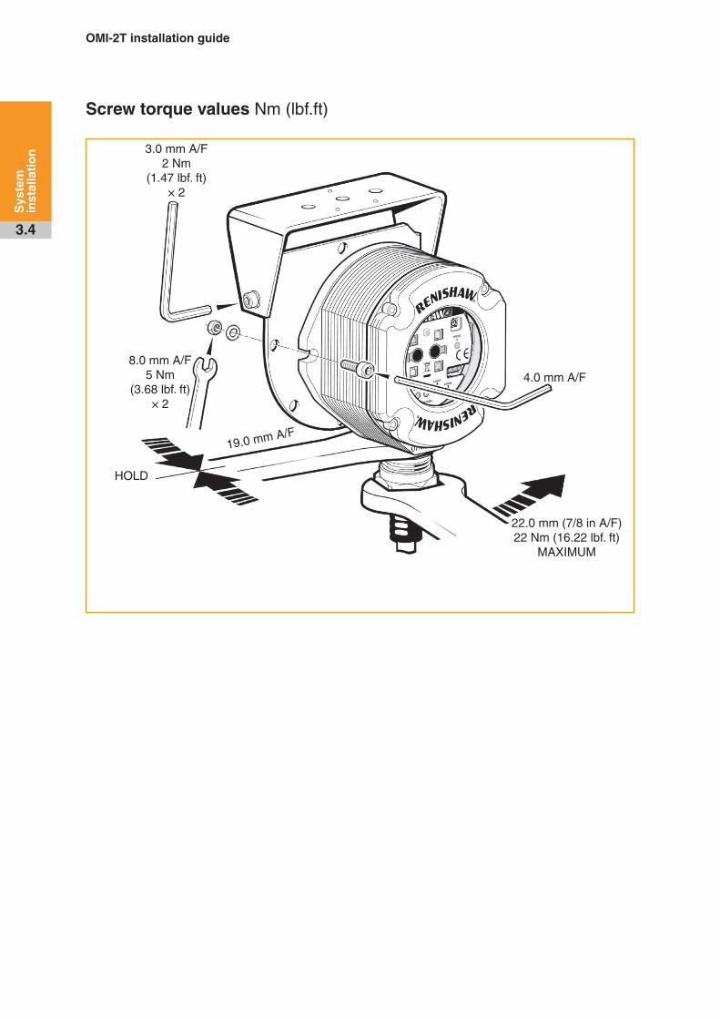
Screw torque values Nm (lbf .ft)
3 .0 mm A/F 2 Nm
(1 .47 lbf . ft) × 2
8 .0 mm A/F 5 Nm
(3 .68 lbf . ft) × 2
HOLD
19 .0 mm A/F
4 .0 mm A/F
22 .0 mm (7/8 in A/F) 22 Nm (16 .22 lbf . ft)
MAXIMUM

4.1
Maintenance
Maintenance
You may undertake the maintenance routines described in these instructions .
Further dismantling and repair of Renishaw equipment is a highly specialised operation, which must be carried out at authorised Renishaw Service Centres .
Equipment requiring repair, overhaul or attention under warranty should be returned to your supplier .
Cleaning the interface
Wipe the window of the interface with a clean cloth to remove machining residue . This should be done on a regular basis to maintain optimum transmission .
CAUTION: The OMI-2T has a glass window, handle with care if broken to avoid injury .

OMI-2T installation guide
4.2
Mai
nte
nan
ce
Removing the OMI-2T window
It is not necessary to remove the OMI-2T from the machine when adjusting the switch or installing replacement parts .
The window may be removed and replaced as described below to change the switch settings .
To remove the OMI-2T window
A
B
1 . Clean the OMI-2T to ensure no debris enters the unit .
2 . Remove the four cover screws, using a 2 .5 mm A/F hexagon key . Two screws are short and two are long . Two of the cover holes are threaded A, and two are plain B .
3 . The window fits tightly on the OMI-2T body, and is removed using the two long screws, which are inserted into the threaded holes A .
CAUTION: DO NOT remove the window by twisting or rotating .
A
A
Tighten each screw a few turns at a time to pull the window up evenly . When it is clear of the body, remove the window and screws completely .
Fitting the OMI-2T window
1 . Before fitting the window, check for any damage to screws or scratch marks which could prevent sealing .
2 . Ensure the O-ring seating C in the OMI-2T body is clean .
A
B
5 . Place the window complete with the O-ring onto the OMI-2T body .
NOTE: The O-ring should be lightly lubricated with grease .
6 . Insert the long screws into holes B and tighten each screw a few turns at a time to pull the window down evenly . There may be some resistance due to some compression of air trapped inside the body .
C
D
E
3 . Ensure that the O-ring D and window E are clean .
4 . Insert the two short screws into window holes A, and tighten .
M3 screws (A) 2 .5 mm A/F × 2 0 .3 to 0 .5 Nm (0 .22 to 0 .37 lbf .ft)
M3 screws (B) 2 .5 mm A/F × 2 0 .9 to 1 .1 Nm (0 .66 to 0 .81 lbf .ft)
A
B
A
B

5.1
Fault-finding
Symptom Cause Action
Probe fails to switch on or switch off.
Installation / CNC program fault . Correct the M-code wiring and/or the CNC program .
Both Probe 1 and Probe 2 LEDs are lit on interface due to both M-codes being active .
Correct M-codes in CNC program .
The probe is out of the start range .
Change the CNC program to bring the probe within the start range of the OMI-2T and ensure that the appropriate start range is selected .
The transmission beam is obstructed .
Clean the OMI-2T window and remove any obstructions .
Incompatible probe / probe transmission setting .
Ensure the probe switch on / switch off method is set to optical on / optical off .
Change the probe or probe setting to modulated and appropriate start code (Probe 1 and Probe 2, see the probe installation guide) .
Incorrect Machine Start setting . Reconfigure the Machine Start setting SW1 and SW2 .
Dead probe batteries . Replace the probe batteries .
Optical interference is blocking the start signal .
Check the OMI-2T visual diagnostics . For instructions describing how to check the visual diagnostics (see “OMI-2T visual diagnostics” on page 2 .2) .
Remove the source of interference or reposition the OMI-2T such that interfering light does not shine onto the OMI-2T window or probe window .

OMI-2T installation guide
5.2
Fau
lt-f
ind
ing
Symptom Cause Action
The probe stops in mid-cycle.
orAn unexpected error occurs during a probing cycle.
orAn unexpected trigger occurs during the probing cycle.
The transmission beam is obstructed .
Remove the obstruction .
Optical interference . Remove the source of interference or reposition the OMI-2T such that interfering light does not shine into the OMI-2T window .
Intermittent wiring fault . Correct wiring .
The probe has moved outside the reception range .
Change the CNC program to bring the probe within the reception range of the OMI-2T and ensure that the appropriate reception range is selected .
The probe has not been triggered for more than 90 minutes .
Restart the probe and ensure that the probe is not idle for 90 minutes .
The probe switches on, but the OMI-2T error LED remains lit.
Interfering light source is shining directly into the OMI-2T window .
Check the OMI-2T visual diagnostics . For instructions describing how to check the visual diagnostics (see “OMI-2T visual diagnostics” on page 2 .2) .
Remove the source of interference or reposition the OMI-2T such that the interfering light does not shine into the OMI-2T window .
The probe is out of the reception range .
Check the signal condition LED .
Change the CNC program to move the probe into the reception range of the OMI-2T and ensure the appropriate reception range is selected .
A signal is being received from a probe on an adjacent machine tool .
Change the adjacent probe to low power mode or change the OMI-2T reception range to 50%, if this range is acceptable .
Installation / CNC program fault . Check wiring and CNC program .
The probe indicates low battery condition, but the machine control does not.
Installation / CNC program fault . Correct low battery SSR wiring and/or CNC program .

5.3
Fau
lt-f
ind
ing
Symptom Cause Action
The machine control does not respond to the probe being triggered or seated.
Probe is not switched on . Attempt to switch it on .
Probe is out of range . Change the CNC program to bring the probe within the reception range .
Installation / CNC program fault . Correct the probe status output(s) wiring and CNC program .
A signal is being received from a probe on an adjacent machine tool .
Change the adjacent probe to low power mode or change the OMI-2T reception range to 50%, if this range is acceptable .
Probe triggers but the OMI-2T does not respond.
The OMP400 or OMP600 has the 3 second switch-on mode selected .
Reconfigure the OMP400 or OMP600 to the standard switch-on delay .
The probe is out of range . Review the performance envelopes .
The transmission beam obstructed .
Check that the probe and OMI-2T windows are clean, and remove any obstruction .
The probe is set to legacy transmission .
Reconfigure to modulated transmission .

OMI-2T installation guide
5.4
Fau
lt-f
ind
ing
This page is intentionally left blank .
6.1
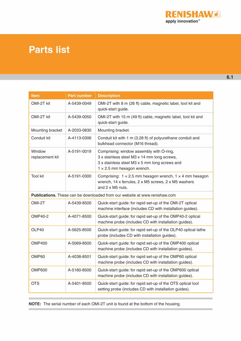
Parts list
Item Part number Description
OMI-2T kit A-5439-0049 OMI-2T with 8 m (26 ft) cable, magnetic label, tool kit and quick-start guide .
OMI-2T kit A-5439-0050 OMI-2T with 15 m (49 ft) cable, magnetic label, tool kit and quick-start guide .
Mounting bracket A-2033-0830 Mounting bracket .
Conduit kit A-4113-0306 Conduit kit with 1 m (3 .28 ft) of polyurethane conduit and bulkhead connector (M16 thread) .
Window replacement kit
A-5191-0019 Comprising: window assembly with O-ring, 3 x stainless steel M3 x 14 mm long screws, 3 x stainless steel M3 x 5 mm long screws and 1 × 2 .5 mm hexagon wrench .
Tool kit A-5191-0300 Comprising: 1 × 2 .5 mm hexagon wrench, 1 × 4 mm hexagon wrench, 14 x ferrules, 2 x M5 screws, 2 x M5 washers and 2 x M5 nuts .
Publications. These can be downloaded from our website at www .renishaw .com
OMI-2T A-5439-8500 Quick-start guide: for rapid set-up of the OMI-2T optical machine interface (includes CD with installation guides) .
OMP40-2 A-4071-8500 Quick-start guide: for rapid set-up of the OMP40-2 optical machine probe (includes CD with installation guides) .
OLP40 A-5625-8500 Quick-start guide: for rapid set-up of the OLP40 optical lathe probe (includes CD with installation guides) .
OMP400 A-5069-8500 Quick-start guide: for rapid set-up of the OMP400 optical machine probe (includes CD with installation guides) .
OMP60 A-4038-8501 Quick-start guide: for rapid set-up of the OMP60 optical machine probe (includes CD with installation guides) .
OMP600 A-5180-8500 Quick-start guide: for rapid set-up of the OMP600 optical machine probe (includes CD with installation guides) .
OTS A-5401-8500 Quick-start guide: for rapid set-up of the OTS optical tool setting probe (includes CD with installation guides) .
NOTE: The serial number of each OMI-2T unit is found at the bottom of the housing .

Renishaw plc
New Mills, Wotton-under-Edge, Gloucestershire, GL12 8JR United Kingdom
T +44 (0)1453 524524 F +44 (0)1453 524901 E [email protected]
www.renishaw.com
For worldwide contact details, visit www.renishaw.com/contact
*H-5439-8510-05*© 2010–2016 Renishaw plc Issued: 06: 2016 Part no. H-5439-8510-05-A
Related Documents