Installation Installation Guide Wireless HD Kit GWAV8141K

Welcome message from author
This document is posted to help you gain knowledge. Please leave a comment to let me know what you think about it! Share it to your friends and learn new things together.
Transcript
InstallationInstallation GuideWireless HD Kit
GWAV8141K


3
Table of Contents
Package Contents 4
Overview 5
Wall Mount 7
Installation 8
Remote Control 12
Selecting Specific Ports 14
LED Indication 14
IR Blast 15
IR Extender 15
Video Format Support 15
Audio Format Support 15
Connection Between the Transmitter Unit and Receiver Unit 16
Factory Reset 16
Firmware Upgrade / Configuration Update 17
Streaming Mode 17
FCC Statement 17
CE Compliance 17
Limited Warranty 18
Contact 18

4
Package Contents
1 x Wireless HD Transmitter1 x Wireless HD Receiver1 x Remote Control2 x Wireless HD Stand1 x Component to VGA Adapter1 x IR Blast2 x Power Adapter1 x Installation Guide1 x Warranty Card

5
Overview
Transmitter Unit
Front ViewPower/Link LED1. HDMI1 LED2. HDMI2 LED3. PC LED4. AV LED5. IR Receiver6. Front Panel Pushbutton 7.
*Note: For the audio part of a Component media source, please use the PC Audio Input Port with a 3.5mm to RCA Cable (Not included and sold separately – IOGEAR Part No: G2LMMRCA006).**Note: If you wish to use the PC Video Input Port for Component (YPbPr) media source, please use the included Component to VGA Adapter.
Rear ViewHDMI2 Input Port8. HDMI1 Input Port9. AV Input Port (Composite)10. IR Blast Output Port11. PC Audio Input Port 12. (3.5mm Mini Stereo Jack)*PC Video Input Port (VGA)**13. LAN Port14. DC Power Jack15.
1
2
4
6
3
5
7
8
9
10
11
12
13
14
15

6
Receiver Unit
Front ViewPower/Link LED1. HDMI LED2. Component LED3. AV LED4. IR Receiver5. Front Panel Pushbutton 6.
*Note: IR Extender not included.**Note: For the audio part of a Component media source, please use the PC Audio Input Port with a 3.5mm to RCA Cable (Not included and sold separately – IOGEAR Part No: G2LMMRCA006).
Rear ViewHDMI Output Port7. AV Output Port (Composite)8. IR Extender Input Port*9. PC Audio Output Port (3.5mm Mini 10. Stereo Jack)**Component Video Output Port (YPbPr)11. USB Firmware Upgrade Port12. LAN Port13. DC Power Jack14.
1
2
4
6
3
9
10
12
13
14
5
7
11
8

7
Wall Mount
Hang the unit on the wall by using the two screw holes on the unit.
2
1

8
Installation
Note: Please make sure your displays and media sources are turned off before you start.
1 HDMI Media SourceConnect a HDMI cable from the media source’s HDMI output to the transmitter unit’s HDMI input
2 VGA Media SourceVideo – Connect a VGA cable from the
media source’s VGA output to the transmitter unit’s VGA input
Audio – Connect a 3.5mm stereo audio cable (Not included and sold separately - IOGEAR Part No: G2LMM006) from the media source’s audio output to the transmitter unit’s PC Audio-In port
3 Composite Media SourceConnect a composite cable from the media source’s composite output to the transmitter unit’s composite input
Step 1Connect your media sources to the transmitter unit.
4 Component Media SourceVideo – Connect the included Component
to VGA Adapter to the VGA Input of the transmitter unit, then connect a Component video (YPbPr) cable from the media source’s Component output to Component connection of the Component to VGA Adapter
Audio – Connect a 3.5mm to RCA cable (Not included and sold separately – IOGEAR Part No: G2LMMRCA006) from the media source’s audio output to the transmitter unit’s PC Audio-In port
2
1 3
Blu-ray Player
VCR
PC
DVR
4
4

Note: If the location of the IR sensor for your media source is not found, you can point the media source’s remote directly in front of the media source, then search for the IR sensor’s location by controlling the media source in different area in the front panel until you find the spot that the media source can be able to received the signal from the remote control.
9
Step 2Connect the IR Blast to the IR-Out Port from the Transmitter unit. Then stick the IR blast directly in front of each of the IR sensor of your media source devices
10
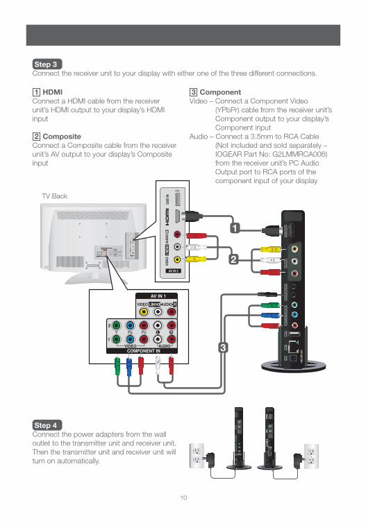
1 HDMIConnect a HDMI cable from the receiver unit’s HDMI output to your display’s HDMI input
2 CompositeConnect a Composite cable from the receiver unit’s AV output to your display’s Composite input
Step 3Connect the receiver unit to your display with either one of the three different connections.
Step 4Connect the power adapters from the wall outlet to the transmitter unit and receiver unit. Then the transmitter unit and receiver unit will turn on automatically.
3 ComponentVideo – Connect a Component Video
(YPbPr) cable from the receiver unit’s Component output to your display’s Component input
Audio – Connect a 3.5mm to RCA Cable (Not included and sold separately – IOGEAR Part No: G2LMMRCA006) from the receiver unit’s PC Audio Output port to RCA ports of the component input of your display
2
1
3
TV Back

11
Tips: If the transmitter unit and receiver unit are not establishing the wireless connection:1.
Please make sure they are both in the same WiFi Channel.a. If they are already in the same WiFi Channel, try to unplug the power on both transmitter b. unit and receiver unit and plug it back in to perform a power cycle to let them reset themselves.If none of the above works, please refer to the Factory Reset section to perform a c. factory reset on both transmitter unit and receiver unit.
If the connection has been established and you can see the IOGEAR screen; however, 2. when you play a media from a source and it’s not showing on your display:
Please make sure the cables are properly connected.a. Please make sure you set the receiver unit to the correct output port.b. Check to your transmitter unit is switched to the correct port for your specific media c. source.Please make sure the display supports the resolution that the media source is streaming d. at. For example, if you are using a 720p HD display to play a full 1080p content, you would need to downscale the source’s resolution to 720p to match the display.
Step 5Turn on your display
Step 6The Power/Link LEDs on the transmitter unit and receiver unit should be flashing, wait till the connection is established (this usually take about 1 to 2 minutes), then you will see the Power/Link LED will stop flashing which means the connection between the transmitter unit and receiver unit is successfully established. You should now see the IOGEAR startup screen on your display, if not, please refer to the Tips at the end of this section for troubleshooting.
Step 7Select the specific input from the transmitter unit and the specific output from the receiver unit by using the remote control or the front panel pushbutton from the units.
Final StepTurn on your media source

HDMI2
POWER
AUDIO INVIDEO IN
RECEIVER
TRANSMITTER
INFO
HDMI1
HDMI2
PC PC
AV AV
HDMI1
VIDEO OUT
AV
COMP
HDMI
WiFiCH 2
WiFiCH 1
LAN
12
Remote Control
POWER ON If the transmitter unit and receiver unit are powered off with the Power/Link LED • on, press the power button will turn on both transmitter unit and receiver unit simultaneouslyIf the transmitter unit and receiver unit are powered off with the Power/Link • LED off, you need to press the power button to turn on the transmitter unit and receiver unit individually
OFF If the transmitter unit and receiver unit are powered on with the Power/Link LED • on, press the power button will turn both transmitter unit and receiver unit off simultaneously with the Power/Link LED staying onIf the transmitter unit and receiver unit are powered on with the Power/Link LED • on, press and hold the power button for 6 seconds will turn both transmitter unit and receiver unit off simultaneously with the Power/Link LED offIf the transmitter unit and receiver unit are powered on with the Power/Link • LED flashing, you would need to power off the transmitter unit and receiver unit individually
4
52
1
3
1
2 Receiver unit
HDMI Press to select HDMI as the output
Component Press to select Component as the output
AV Press to select Composite as the output
LAN Press and hold the LAN button for 6 seconds to change the connection to Wired Mode3
6
13
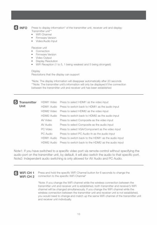
INFO Press to display information* of the transmitter unit, receiver unit and display:Transmitter unit**
WiFi Channel•Firmware Version•Video/Audio Input•
Receiver unitConnection•Firmware Version•Video Output •Display Resolution•WiFi Reception (1 to 5, 1 being weakest and 5 being strongest)•
DisplayResolutions that the display can support
*Note: The display information will disappear automatically after 20 seconds**Note: The transmitter unit’s information will only be displayed if the connection between the transmitter unit and receiver unit has been established
Transmitter Unit
HDMI1 Video Press to select HDMI1 as the video input
HDMI1 Audio Press to switch back to HDMI1 as the audio input
HDMI2 Video Press to select HDMI2 as the video input
HDMI2 Audio Press to switch back to HDMI2 as the audio input
AV Video Press to select Composite as the video input
AV Audio Press to select Composite as the audio input
PC Video Press to select VGA/Component as the video input
PC Audio Press to select PC Audio-In as the audio input
HDMI1 Audio Press to switch back to the HDMI1 as the audio input
HDMI2 Audio Press to switch back to the HDMI2 as the audio input
WiFi CH 1 WiFi CH 2
Press and hold the specific WiFi Channel button for 6 seconds to change the connection to the specific WiFi Channel*
*Note: If you change the WiFi channel while the wireless connection between the transmitter unit and receiver unit is established, both transmitter and receiver’s WiFi channel will be changed simultaneously. If you change the WiFi channel while the wireless connection between the transmitter unit and receiver unit is not established, you would need to change and match up the same WiFi channel of the transmitter unit and receiver unit individually.
4
5
6
Note1: If you have switched to a specific video port via remote control without specifying the audio port on the transmitter unit, by default, it will also switch the audio to that specific port.Note2: Independent audio switching is only allowed for AV Audio and PC Audio.
14
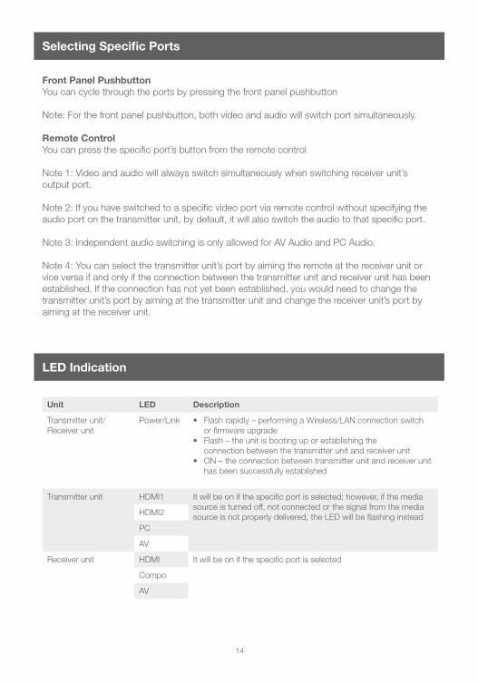
LED Indication
Unit LED Description
Transmitter unit/Receiver unit
Power/Link Flash rapidly – performing a Wireless/LAN connection switch • or firmware upgradeFlash – the unit is booting up or establishing the • connection between the transmitter unit and receiver unitON – the connection between transmitter unit and receiver unit • has been successfully established
Transmitter unit HDMI1 It will be on if the specific port is selected; however, if the media source is turned off, not connected or the signal from the media source is not properly delivered, the LED will be flashing insteadHDMI2
PC
AV
Receiver unit HDMI It will be on if the specific port is selected
Compo
AV
Selecting Specific Ports
Front Panel PushbuttonYou can cycle through the ports by pressing the front panel pushbutton
Note: For the front panel pushbutton, both video and audio will switch port simultaneously.
Remote ControlYou can press the specific port’s button from the remote control
Note 1: Video and audio will always switch simultaneously when switching receiver unit’s output port.
Note 2: If you have switched to a specific video port via remote control without specifying the audio port on the transmitter unit, by default, it will also switch the audio to that specific port.
Note 3: Independent audio switching is only allowed for AV Audio and PC Audio.
Note 4: You can select the transmitter unit’s port by aiming the remote at the receiver unit or vice versa if and only if the connection between the transmitter unit and receiver unit has been established. If the connection has not yet been established, you would need to change the transmitter unit’s port by aiming at the transmitter unit and change the receiver unit’s port by aiming at the receiver unit.

15
IR Blast
This allows you to control your media source by aiming your official remote that comes with your media source at the receiver unit. The signal will then send from the receiver unit back to the transmitter unit. Finally, it will send to your media source via the IR blast.
IR Extender
This is an optional feature that allows you to hide the receiver unit and still able to control your media sources
Video Format Support
This product supports both digital and analog video format:
Digital Video:HDMI – Up to 1080p60
Analog Video:Composite – Up to 480p Component – Up to 1080i60VGA – Up to 1920x1080@60Hz
Audio Format Support
This product supports both digital and analog audio:
Digital Audio – AC-3 Dolby Digital, DTS (Pass Through)Analog Audio – 16bit 2-Channel linear PCM (44.1kHz & 48kHz)

16
Connection Between the Transmitter Unit and Receiver Unit
There are two different kinds of connection between the transmitter unit and receiver unit
WiFi – Wireless Connection1. This is a wireless connection and there are 2 channels to choose from. The default channel is Channel 1; however if you are experiencing any interferences while using Channel 1, you can change it to Channel 2.
LAN - Wired Connection 2. This is a wired connection that requires a solid CAT5e/6 patch cable to be connected to the LAN ports between the transmitter unit and receiver unit
WiFi Channel Frequency Use
Channel 1 5.19GHz (WiFi Ch 38)
Channel 2 5.23GHz (WiFi Ch 46)
This will changes all the settings back to the original default settings.
Step 1Remove the DC power from the transmitter or receiver unit
Step 2Press and hold the Front Panel Pushbutton, then while holding the pushbutton, re-connect the DC power to the transmitter unit or receiver unit
Step 3Keep holding the pushbutton until you see all the LEDs on the unit are flashing rapidly
Final StepRelease the pushbutton then wait for the unit to be reset
Factory Reset
17
Please visit our website at http://avior.iogear.com/support/custom/wirelesshdkit and follow the instructions to upgrade the firmware or configure the units*.
Note: Please make sure all units are using the same firmware version in order to function correctly.
*Note: The transmitter unit and receiver unit set has been pre-configured to Peer-to-Peer Mode. There is no need to re-configure unless you need to change the set into Broadcasting Mode.
Firmware Upgrade / Configuration Update
This equipment has been tested and found to comply with the limits for a Class B digital device, pursuant to Part 15 of the FCC Rules. These limits are designed to provide reasonable protection against harmful interference in a residential setting. This product generates, uses, and can radiate radio frequency energy and, if not installed and used as directed, it may cause harmful interference to radio communications. Although this product complies with the limits for a Class B digital device, there is no guarantee that interference will not occur in a particular installation.
Peer-to-Peer ModeThis is a 1 to 1 streaming mode, which is the default setting of the set.
Broadcasting ModeThis is a 1 to multi streaming mode. It allows a single transmitter unit steaming the content to up to 4 receiver units* simultaneously. After additional receiver units have been purchased, you MUST visit our website at http://avior.iogear.com/support/custom/wirelesshdkit and follow the instructions to upgrade the firmware and configure the units into Broadcasting Mode.
Note: Please make sure all units are using the same firmware version in order to function correctly.
*Note: Additional Wireless HD Receivers sold separately – Part No: GWAV8101R
FCC Statement
Streaming Mode
This device has been tested and found to comply with the following European Union directives: Electromagnetic Capability (89/336/EMC), Low Voltage (73/23/EEC) and R&TTED (1999/5/EC).
CE Compliance

18
Contact
WE’RE HERE TO HELP YOU!NEED ASSISTANCE SETTING UP THIS PRODUCT?
Make sure you:1. Use the live chat at avior.iogear.com to try and solve any issues you may be having with the product2. Visit the Tech Info Library/FAQ on avior.iogear.com (under the Support tab)3. Call the tech support line at 1(866) 946-4327 (U.S. only) or (949) 453-8782
Warranty InformationThis product carries a 1 Year Limited Warranty. For the terms and conditions of this warranty, please go to http://avior.iogear.com/support/warranty or call 1-866-946-4327
Register online at http://avior.iogear.com/register
Important Product InformationProduct ModelSerial Number
Limited Warranty
IOGEAR19641 Da Vinci Foothill Ranch, CA 92610Toll Free: 866-9-IOGEARPhone: 949-453-8782Web site: avior.iogear.comE-mail: [email protected]
Contact


© 2010 IOGEAR®
FUNIOGEAR offers connectivity solutions that are innova-tive, fun, and stylish, helping people enjoy daily life using our high technology products.
GREENIOGEAR is an environmentally conscious company that emphasizes the importance of conserving natural resources. The use of our technology solutions helps reduce electronic waste.
About UsAbout Us
PART NO. M1128
Related Documents