INSTALLATION GUIDE GUARDIANWALL UB / UC POST TYPES

Welcome message from author
This document is posted to help you gain knowledge. Please leave a comment to let me know what you think about it! Share it to your friends and learn new things together.
Transcript

INSTALLATION GUIDE
GUARDIANWALLUB / UC POST TYPES
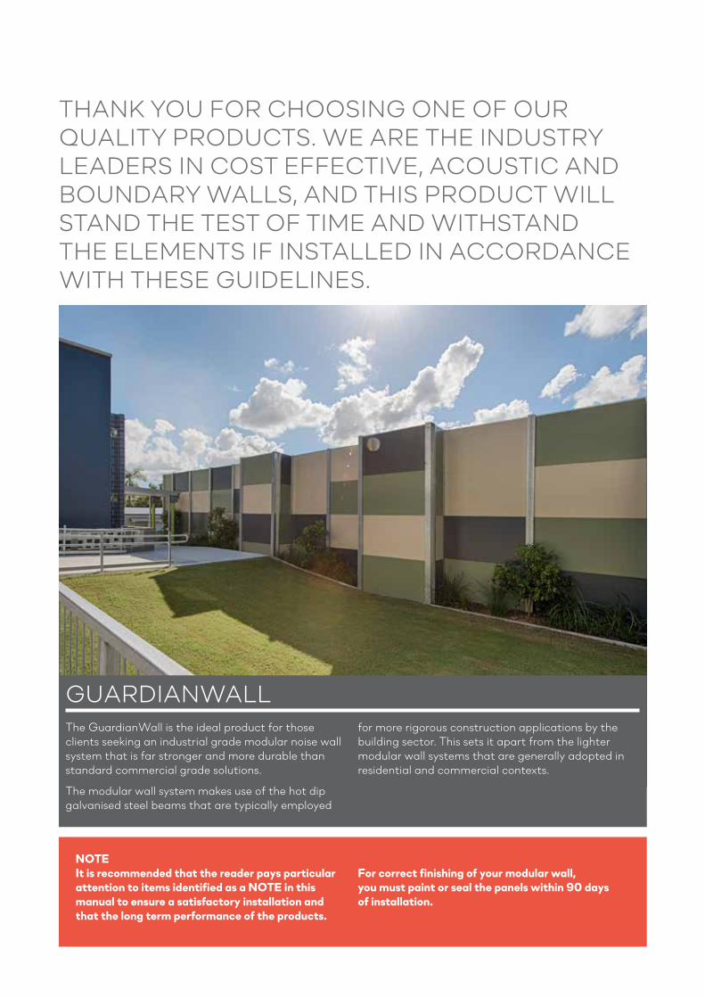
The GuardianWall is the ideal product for those clients seeking an industrial grade modular noise wall system that is far stronger and more durable than standard commercial grade solutions.
The modular wall system makes use of the hot dip galvanised steel beams that are typically employed
for more rigorous construction applications by the building sector. This sets it apart from the lighter modular wall systems that are generally adopted in residential and commercial contexts.
THANK YOU FOR CHOOSING ONE OF OUR QUALITY PRODUCTS. WE ARE THE INDUSTRY LEADERS IN COST EFFECTIVE, ACOUSTIC AND BOUNDARY WALLS, AND THIS PRODUCT WILL STAND THE TEST OF TIME AND WITHSTAND THE ELEMENTS IF INSTALLED IN ACCORDANCE WITH THESE GUIDELINES.
NOTEIt is recommended that the reader pays particular attention to items identified as a NOTE in this manual to ensure a satisfactory installation and that the long term performance of the products.
For correct finishing of your modular wall, you must paint or seal the panels within 90 days of installation.
GUARDIANWALL

CONTENTS
AN INTRODUCTION TO GUARDIANWALL 2
CONTENTS 3
BEFORE YOU START 4
PLANT & EQUIPMENT 5
STEP 1 - DETERMINE CONSTRUCTION LINE, POST HOLE CENTRES, & DEPTHS 6 -7
STEP 2 - POST FITMENT & ALIGNMENT 8 - 10
STEP 3 - CONCRETE THE POSTS 11
STEP 4 - INSTALLING UB INFILLS & SHS PANEL SUPPORTS 12 - 14
STEP 5 - FITTING THE CAPPING CHANNEL TO THE BASE CHANNEL 15
STEP 6 - INSERTING THE WALL PANELS 16 - 17
STEP 7 - INSERTING THE JOINING PROFILE 18
STEP 8 - INSERTING CONSECUTIVE PANELS 19
STEP 9 - FITTING THER CAPPING CHANNEL TO THE TOP PANEL 20
ADDITIONAL - CUTTING THE PANELS 21
NOTES 22 - 23
GUARDIAN WALL INSTALLATION GUIDE 3

7 DAY A WEEK TECHNICAL AND INSTALLATION ADVICE IS AVAILABLE
BY PHONING 1300 556 957 AND SELECTING THE AFTER HOURS OPTION
The recommendations detailed by ModularWalls in this guide are formulated along the lines of good building practice. They form a “common-sense” approach and are not intended to be an exhaustive statement of all the relevant data. Further, as the success of projects depend on factors outside the control of ModularWalls (e.g. quality of workmanship, particular design, detail requirements, etc.), we accept no responsibility for, or in connection with, the quality of the projects or their suitability when completed.
If you are in any doubt please seek independent advice or contact ModularWalls. We are always happy and available to answer questions regarding installation procedures, no matter how small or insignificant you think they may be. 7 day technical and installation advice is available on 1300 556 957.
BEFORE YOU START

PLANT & EQUIPMENT
NOTE: Guide only – Individual sites and installation requirements will vary.
• Excavator with auger bit and extensions. The size of the excavator required will be dependent on the geotechnical conditions present. A Ø450mm or Ø600mm auger are typical; the larger diameter will allow slightly more tolerance on adjusting post centres but also requires additional concrete.
• Telehandler (“Manitou”) or Franna crane. A jib or crane hook is also required for Post & Panel placement
• Hinged Eye Beam Clamp (if using a Telehandler) or Universal Plate Clamp (if using a Franna).
• Generator (single-phase output), for operating mechanical hand tools.
• “Rough-terrain” 4x4 scissor lift with a 3m+ platform length (or boom lift if access to the line of the wall is not possible). For higher walls (above 3m), this is a critical item for safe panel installation.
• Block and tackle (0.5T min.) – For lowering the posts, but again this is dependent on the individual methods employed
• Oxyacetylene bottles and cutting torch – In case you need to adjust the length of a UB/UC prior to placement into the footing. Remember to place cut end into the footing.
• Mechanical hand tools and construction aids – spirit level, tape measure, impact drill with 5/16” and 3/8” hex driver bits, angle grinder, circular saw, line marking paint, string line, shovel, caulking gun.
• Laser level and staff.
• Lengths of timber 70 x 45 (or similar) to clamp and brace posts in position.
• Threaded rod with nuts and washers required for clamping units.
GUARDIAN WALL INSTALLATION GUIDE 5
STEP 1: DETERMINE CONSTRUCTION LINE, POSTHOLE CENTRES & DEPTHS
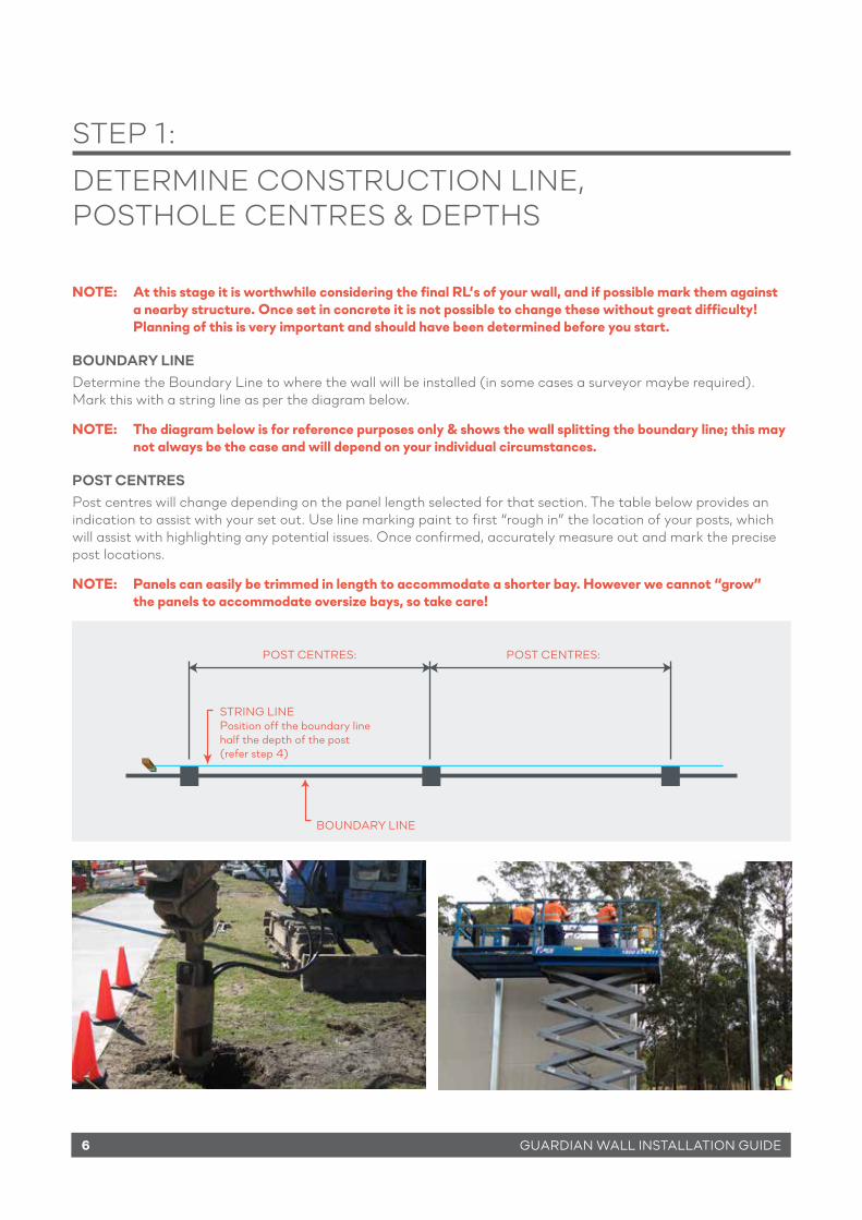
NOTE: At this stage it is worthwhile considering the final RL’s of your wall, and if possible mark them against a nearby structure. Once set in concrete it is not possible to change these without great difficulty! Planning of this is very important and should have been determined before you start.
BOUNDARY LINEDetermine the Boundary Line to where the wall will be installed (in some cases a surveyor maybe required). Mark this with a string line as per the diagram below.
NOTE: The diagram below is for reference purposes only & shows the wall splitting the boundary line; this may not always be the case and will depend on your individual circumstances.
POST CENTRESPost centres will change depending on the panel length selected for that section. The table below provides an indication to assist with your set out. Use line marking paint to first “rough in” the location of your posts, which will assist with highlighting any potential issues. Once confirmed, accurately measure out and mark the precise post locations.
NOTE: Panels can easily be trimmed in length to accommodate a shorter bay. However we cannot “grow” the panels to accommodate oversize bays, so take care!
POST CENTRES:
STRING LINEPosition off the boundary line half the depth of the post(refer step 4)
BOUNDARY LINE
POST CENTRES:
6 GUARDIAN WALL INSTALLATION GUIDE

GUARDIAN WALL INSTALLATION GUIDE 7
STEP 1: DETERMINE CONSTRUCTION LINE, POSTHOLE CENTRE & DEPTHS
Standard Panel Length Maximum Post Centres
2400mm 2440mm2700mm 2740mm3000mm 3040mm
POSTHOLE DEPTHS & DIAMETERAs GuardianWalls are engineered to suit the specific requirements of the site, there is no standard table for posthole depths or diameters. Refer to the engineering specification for your individual project.
As a general guide (not to be used for construction), for a soil bearing capacity of 100 kPa, the posthole depth should be a minimum 1/3 below ground in relation to the wall height out of ground. For example, a 6m high wall would require at least 2m of post embedment within the footing. Steel reinforcing cages are typically not necessary if you have a continuous post embedment, and a minimum concrete cover of 100mm is also recommended. This does not take into account specific site requirements, unstable/ aggressive soil types and wind region.
A post hole diameter of Ø450 mm or Ø600 mm is typical (standard auger sizes), but must again be selected for your individual site.

STEP 2: POST FITMENT & ALIGNMENT
There are a few typical methods that can be employed when positioning the support columns. Select the one that best suits the individual job requirements, plant available, and Civil Contractor competency. Ultimately it is up to the installer to make an assessment and decision on the best procedure to be used (and may not be detailed below).
NOTE: Maintaining the vertical alignment as well as X & Y alignment is critical and will be the foundation for a smooth installation. If the posts are installed correctly then the panelling will be easy!
Significant care should be taken when lifting and handling GuardianWall posts. A SWMS should be adopted for this process, also taking into account site-specific PPE requirements. A standard rigging arrangement involves using a jib (or crane hook), block and tackle, attachment and a hinged post clamp.
8 GUARDIAN WALL INSTALLATION GUIDE

STEP 2: POST FITMENT & ALIGNMENT
METHOD 1 – DRY FITMENT OF SUPPORT COLUMNS USING AN ABOVE-GROUND CRADLECradles can be custom-fabricated from RHS steel, with perpendicular outrigger arms and pinch bolts.Alternatively, lengths of timber utilising threaded rods, nuts & washers to create a clamp can be used. The number of frames available will limit the number of posts that can be concreted during the same pour.
These cradles are shimmed between the cradle and the ground to provide a level and correct height surface. The cradles are then staked / pinned into position to limit any movement when installing the post. Take care to keep the posts as vertical as possible during installation, to limit any force on the cradle itself.
The exact post height can be achieved by using a block and tackle in between the jib and the post to perform micro-adjustments. By attaching a laser level staff to the top of the post or having a premarked line on the post face (that is relative to the final height), the post heights can be consistently set against a datum level then locked off to the cradle to maintain the vertical adjustments. A range of photos outlining this process are below.
Diagonal bracing is also a very important consideration for safety and alignment purposes. These braces should be ready and on standby during post installation. A clamp can be used to hold the brace against the side of the post. Always work to a stringline set slightly off the face of the post (≈5-10mm). As pictured, a pre-cut length of wood can also be clamped to the post face to maintain the exact post centres during installation.
NOTE: This method allows for the posts to be set up dry then poured once aligned & secured into position. When pumping or pouring the concrete into the postholes it should be noted that there is a real possibility of the base of the post will move if the concrete is allowed to shoot directly onto the post with force; this should be avoided.
GUARDIAN WALL INSTALLATION GUIDE 9

STEP 2: POST FITMENT & ALIGNMENT
METHOD 2 – WET FITMENT OF SUPPORT COLUMNS USING A SUPPORT BAR THOUGH THE WEB
NOTE: This method is for experienced installers only as there are no second chances once the post is set. It is a difficult method to achieve acceptable post alignment; however, this difficulty is offset by speed of installation. If this method can be perfected and the site / job conditions are conducive, it can be a very quick method of installation. We have installed kilometres of walling using this method, and would recommend using this method only for large jobs where the time onsite is critical and the installation is carried out by experienced personnel.
1. Postholes should be dug and double checked for alignment and size.
2. A string line set up to the face of the post and then the postholes checked again to make sure there will be no clash between the post and the side of the hole.
3. Accurately mark the post centres. Use a stake if line marking paint cannot be relied upon.
4. The post that is to be used for the hole should be placed next to the hole so it is ready to be inserted. Make sure the post will not hamper passage of the concrete trucks or other trades.
5. The method used to set the height of the post should be pre-determined, and all necessary preparations already completed.
6. A retardant should be used in the concrete mix (to slow the drying time) as well as a wet slump confirm both with the certifying Engineer as to how wet is allowable.
7. Pour as many holes as you are comfortable with (10 – 15 is normal, depending on the job difficulty and concrete truck capacity)
8. You will need three teams of people. - 1 person guiding the concrete truck. - 2-3 people. Setting the support columns into the wet concrete - 1 person checking and adjusting the post alignment as they are curing
9. Insert the posts into the wet concrete and brace as required (see notes above regarding bracing).
10. Place two magnetic levels on each post to allow for on-the-spot alignment, as well as retrospective alignment for when the final team member follows behind checking and adjusting as required. (It is recommended to have a series of magnetic levels to ensure you have two levels per post being inserted).
10 GUARDIAN WALL INSTALLATION GUIDE

STEP 3: CONCRETING THE POSTS
A typical concrete grade used is N32, with 15-20mm aggregate size and 80mm slump. This should be confirmed by the certifying Engineer as it will be specific to your job, wind region & soil conditions etc.
NOTE: A “wetter” concrete mix will reduce the amount of force against the post as the concrete is being poured. This in turn will reduce the amount of adjustment needed (if any) to realign the post back to vertical.
MOST IMPORTANT...ASK THE DRIVER TO POUR THE CONCRETE SLOWLY! If you try to rush things by pouring it too fast you will only cause more work later by having ill aligned
posts. Be sure to hose off the excess concrete left behind on the support shoes etc after the pour and before it sets. Rod or vibrate the concrete as required.
After the posts have set and the support shoes have been removed you should mix up a mortar mix with a trowel. Slope the concrete away from the post for damage.
For long-life designs (≥25 years), a zinc-rich industrial preventative coating must be applied to the base of the footing and 100mm min. up the base of the post. ModularWalls recommends “Dulux Durebild STE”, applied thickly (100μm min.).
GUARDIAN WALL INSTALLATION GUIDE 11
Slope concrete awa from post to allow for drainage

STEP 4: INSTALLING UB INFILLS & SHS PANEL SUPPORTS
The diagram above indicates a typical infill arrangement for a visual barrier, where a section of 75x75x2.0mm SHS has been used to raise the height of the bottom panel. This is standard practice where there is a gap under the wall (such as a level visual-barrier installed over undulating ground). When cutting the SHS to length, it should be 5mm shorter than the gap between the footing and the bottom panel level; this is to allow for the thickness of the top/bottom panel capping and the plastic SHS cap.
NOTE: An alternate method is to use a clamping angle which is not detailed in this guide.
UB infill with continue for the full length
Sika Flex between UB infill and 7SHS + FULL LENGTH
Glue UB to back with liquid nails or similar
Panel to sit on top of 7SHS
Set infill and SHS onto a level footing
12 GUARDIAN WALL INSTALLATION GUIDE

STEP 4: INSTALLING UB INFILLS & SHS PANEL SUPPORTS
1. Apply Sikaflex Pro to the web of the UB.
2. Insert UB infill.
3. Insert panels and sika bewtween Panel and UB infill.
4. Apply bead of Sika between the edge of the UB flange and the UB infill
GUARDIAN WALL INSTALLATION GUIDE 13

STEP 4: INSTALLING UB INFILLS & SHS PANEL SUPPORTS
14 GUARDIAN WALL INSTALLATION GUIDE
UB infill (to accept the wall panel) can be seen installed here
75mm SHS can be seen here. It has been cut to the correct height ready to accept the base panel.
Seal between the SHS and the UB infill interface to prevent wandering of the 75mm SHS (full length beads on both sides).
the panels can be seen here resting on the
75mm SHS.

This should be performed before installation of any panels into the post/infill system. If any section of the long edge of the panel has been damaged (due to transport or mishandling), then fit the capping channel over this edge. Apply liquid nails or similar to the internal radius as pictured below (full length).
NOTE: That the capping channel will be slightly shorter than the panel. Start at one end of the panel, approx 5mm in and carefully ease the capping channel over the panel. Once fitted, tap the capping channel to make sure it is seated correctly.
STEP 5: FITTING THE CAPPING CHANNEL TO THE BASE PANEL
Capping Channel
GUARDIAN WALL INSTALLATION GUIDE 15

STEP 6: INSERTING THE WALL PANELS
METHOD 1 – USING AN ALL-TERRAIN SCISSOR LIFT
NOTE: The first step is to establish a safety area via bunting etc. in the area that the Scissor Lift will be operating, in case a panel should fall. The use of a spotter on the ground is also recommended that is outside the bunting.
NOTE: Site / job specific regulations regarding lifting and working at heights should be considered before undertaking this method.
1. Position the Scissor Lift side-on to the section of wall that you will be installing.
2. Carefully load the panels into the platform and raise the platform (with three men) to the required working height.
3. With one person at either end, lift the panel vertically and insert into the top recesses of the post. The panel must be guided down at an even rate or it will jam. This can be done by inserting the panel into the rebate by approx. 200 mm and have the third person lower the platform. If the panels are being installed all the way to ground level then there should be 2 people below that catch the first panel and guide it down. These two people should then fit the panel joining system (as outlined in Step 7).
16 GUARDIAN WALL INSTALLATION GUIDE

STEP 6: INSERTING THE WALL PANELS - Crane
METHOD 2 – USING AN ALL-TERRAIN SCISSOR / BOOM LIFT AND PANEL GRAB WITH CRANE
NOTE: Site / job specific regulations regarding lifting and working at heights should be considered beforeundertaking any works. A safe lifting procedure should also be considered before performing any lifts.
1. Position the Scissor or Boom lift in a position that allows you to guide the panel into the rebates of the post.
2. A panel grab (available from most hire outlets) that is generally acceptable for lifting 75 mm panels is suitable for this application.
3. A test lift should be performed on a spare or test piece of panel, and an installation method agreed upon before lifting any panels into the air. Check the ‘Grab’ is in working condition, and whether it will cause any surface damage to the panels.
GUARDIAN WALL INSTALLATION GUIDE 17

STEP 7: INSERTING THE JOINING PROFILE
Insert the joining profile into the bottom panel recesses, making sure it is seated all the way down.
18 GUARDIAN WALL INSTALLATION GUIDE

STEP 8: INSERTING CONSECUTIVE PANELS
Repeating Step 6, guide the second panel down on top of the bottom panel and press down to seat the panels. Care should be taken to make sure everything is in place before attempting to press the panels together. If they do not align correctly with light downward pressure remove the top panel and inspect the polystyrene joint. It may be necessary to ‘Tap’ the panel down using a heavy block of wood in a ‘pivoted slapping action’ to bring it together completely (see picture below).
GUARDIAN WALL INSTALLATION GUIDE 19

STEP 9: FITTING THE CAPPING CHANNEL TO THE TOP PANEL
Apply ‘liquid nails fast grab’ or similar along the 90 degree folds (as pictured below). Ease the wall capping over the panel starting at one end and press down. Once set, the liquid nails will stop any unwanted movement or possible ‘lifting’ via thermal expansion.
20 GUARDIAN WALL INSTALLATION GUIDE

ADDITIONAL: CUTTING THE PANELS
Wear the appropriate safety equipment for performing the task. Eye wear, hearing protection & a dust mask. The use of a dust extraction vacuum is recommended.
The panels can be cut using a circular saw with a timber blade. Remember to always support or catch the piece you’re cutting off as it may break towards the end of your cut if you don’t.
If your circular saw doesn’t have a deep enough blade to cut through the panel in one sweep then you must cut through one face and carefully turn the panel over and cut through the other.
NOTE: Panel embedment within the post web will vary depending on your individual wall height and allowable post deflection rates. Please consult ModularWalls™ for further advice if you’re embedment is less than 25 mm at either end or the panel has the ability to shift and allows less than 25mm embedment.
GUARDIAN WALL INSTALLATION GUIDE 21

NOTES:
22 GUARDIAN WALL INSTALLATION GUIDE

NOTES:
GUARDIAN WALL INSTALLATION GUIDE 23

7 DAY A WEEK TECHNICAL AND INSTALLATION ADVICE IS AVAILABLE BY
PHONING 1300 556 957 AND SELECT THE AFTER HOURS OPTION
www.modularwalls.com.au
WITH A REPUTATION FOR QUALITY AND INNOVATION, MODULARWALLS®PROVIDED REVOLUTIONARY WAYS TO
CREATE STYLISH AND COST-EFFECTIVEWALLS AND FENCING.
Related Documents