installation guide ICON classic benching

Welcome message from author
This document is posted to help you gain knowledge. Please leave a comment to let me know what you think about it! Share it to your friends and learn new things together.
Transcript
installation guideICON classic benching
....................................................................................................................................................................................................................................................P2Please contact [email protected] if you are missing any parts, have difficulty with assembly, or have any product related questions.
ICON Installation Guide
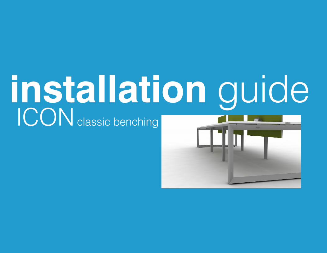
Single RunFrame Assembly ........................................................................4Worksurfaces and Electrical .......................................................5Attaching Worksurfaces to Frame ..............................................6Installing optional accessories ...................................................7Installing Screens .......................................................................8Jumpers .....................................................................................9Power Pole ...............................................................................10
Double RunFrame Assembly ......................................................................12Worksurfaces and Electrical .....................................................13Attaching Worksurfaces to Frame ............................................14Installing optional accessories .................................................15Installing Screens and Remaining Worksurfaces ....................16Jumpers ...................................................................................17Power Pole ...............................................................................18
Modesty Panel ..........................................................................19
Index

....................................................................................................................................................................................................................................................P3Please contact [email protected] if you are missing any parts, have difficulty with assembly, or have any product related questions.
ICON installation guide SINGLE RUN
Phase 1 Frame Assembly
....................................................................................................................................................................................................................................................P4Please contact [email protected] if you are missing any parts, have difficulty with assembly, or have any product related questions.
ICON Single Run Installation Guide
1
1
2
2
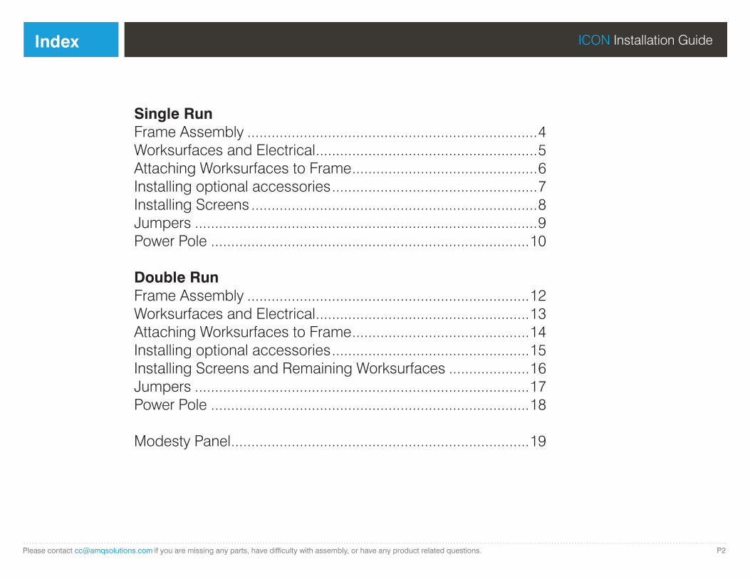
Screw the outer-to-inner horizontal beams (H-bar) to the top of each outside leg (O-Leg) using the M8*25 screws. Then screw the outer-to-inner H-bars to the bottom of each O-Leg using the M6*20 screws.
Rest the outer-to-inner H-bars on the top of the inner legs (U-Leg). Then rest the inner-to-inner H-bars on top the U-legs. Screw the horizontal beam connectors and H-bars to the frame using the M6*20 screws.
3
3
Adjust the glides to level the frame as needed. We suggest using a leveling glide for best accuracy.
Bottom screws should be installed first on all frame bars.
NOTE: For 60” or 72” ICON frame bars the bars should be aligned so that the large oval hole is located on the inside of the bench to accommodate future returns.
....................................................................................................................................................................................................................................................P5Please contact [email protected] if you are missing any parts, have difficulty with assembly, or have any product related questions.
ICON Single Run Installation Guide Assembling Worksurfaces and Electrical Phase 2
1
1
2
3
3
4
5
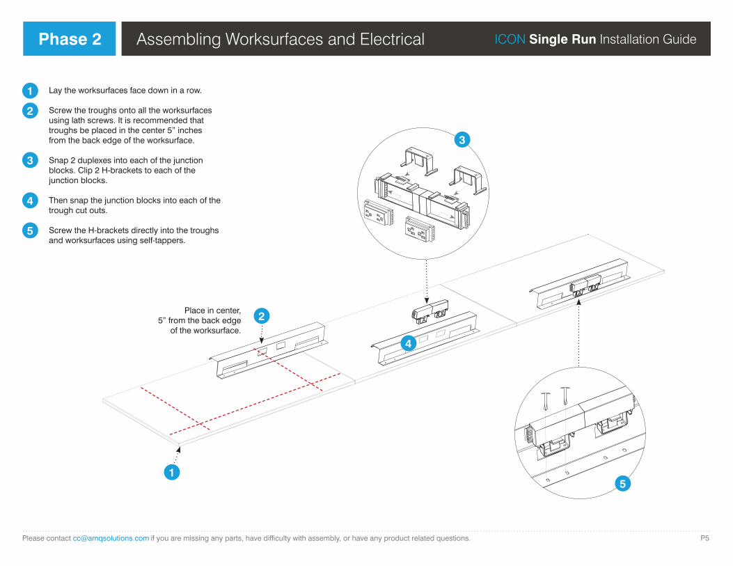
Lay the worksurfaces face down in a row.
Screw the troughs onto all the worksurfaces using lath screws. It is recommended that troughs be placed in the center 5” inches from the back edge of the worksurface.
Snap 2 duplexes into each of the junction blocks. Clip 2 H-brackets to each of the junction blocks.
Then snap the junction blocks into each of the trough cut outs.
Screw the H-brackets directly into the troughs and worksurfaces using self-tappers.
Place in center, 5” from the back edge
of the worksurface.
2
5
4
....................................................................................................................................................................................................................................................P6Please contact [email protected] if you are missing any parts, have difficulty with assembly, or have any product related questions.
ICON Single Run Installation Guide Attaching Worksurfaces to FramePhase 3
1 5
26
3
4
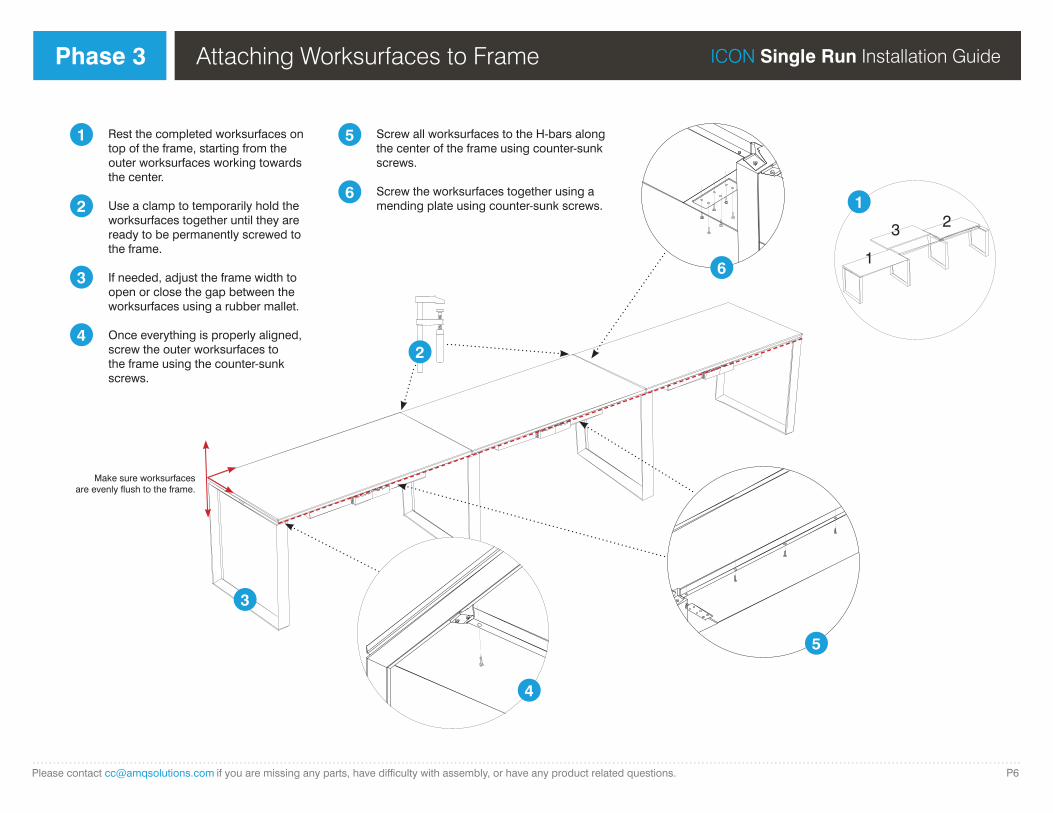
Rest the completed worksurfaces on top of the frame, starting from the outer worksurfaces working towards the center.
Use a clamp to temporarily hold the worksurfaces together until they are ready to be permanently screwed to the frame.
If needed, adjust the frame width to open or close the gap between the worksurfaces using a rubber mallet.
Once everything is properly aligned, screw the outer worksurfaces to the frame using the counter-sunk screws.
Screw all worksurfaces to the H-bars along the center of the frame using counter-sunk screws.
Screw the worksurfaces together using a mending plate using counter-sunk screws. 1
Make sure worksurfaces are evenly flush to the frame.
2
3
4
5
61
3 2
....................................................................................................................................................................................................................................................P7Please contact [email protected] if you are missing any parts, have difficulty with assembly, or have any product related questions.
ICON Single Run Installation Guide Installing Optional AccessoriesPhase 4
1
1
2
2
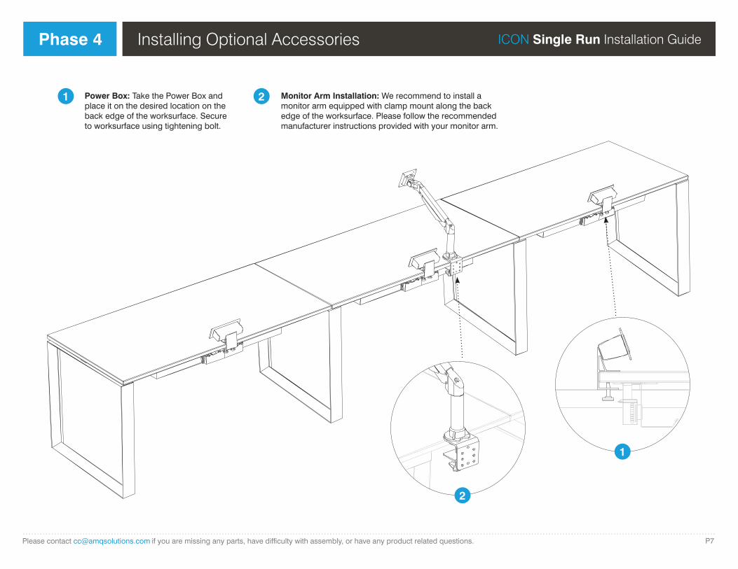
Power Box: Take the Power Box and place it on the desired location on the back edge of the worksurface. Secure to worksurface using tightening bolt.
Monitor Arm Installation: We recommend to install a monitor arm equipped with clamp mount along the back edge of the worksurface. Please follow the recommended manufacturer instructions provided with your monitor arm.
....................................................................................................................................................................................................................................................P8Please contact [email protected] if you are missing any parts, have difficulty with assembly, or have any product related questions.
ICON Single Run Installation Guide
1
Installing ScreensPhase 5
FabricScreen
GlassScreen
* Clip kit includes fit-sleeve for glass screen.
2 3
1
2
3
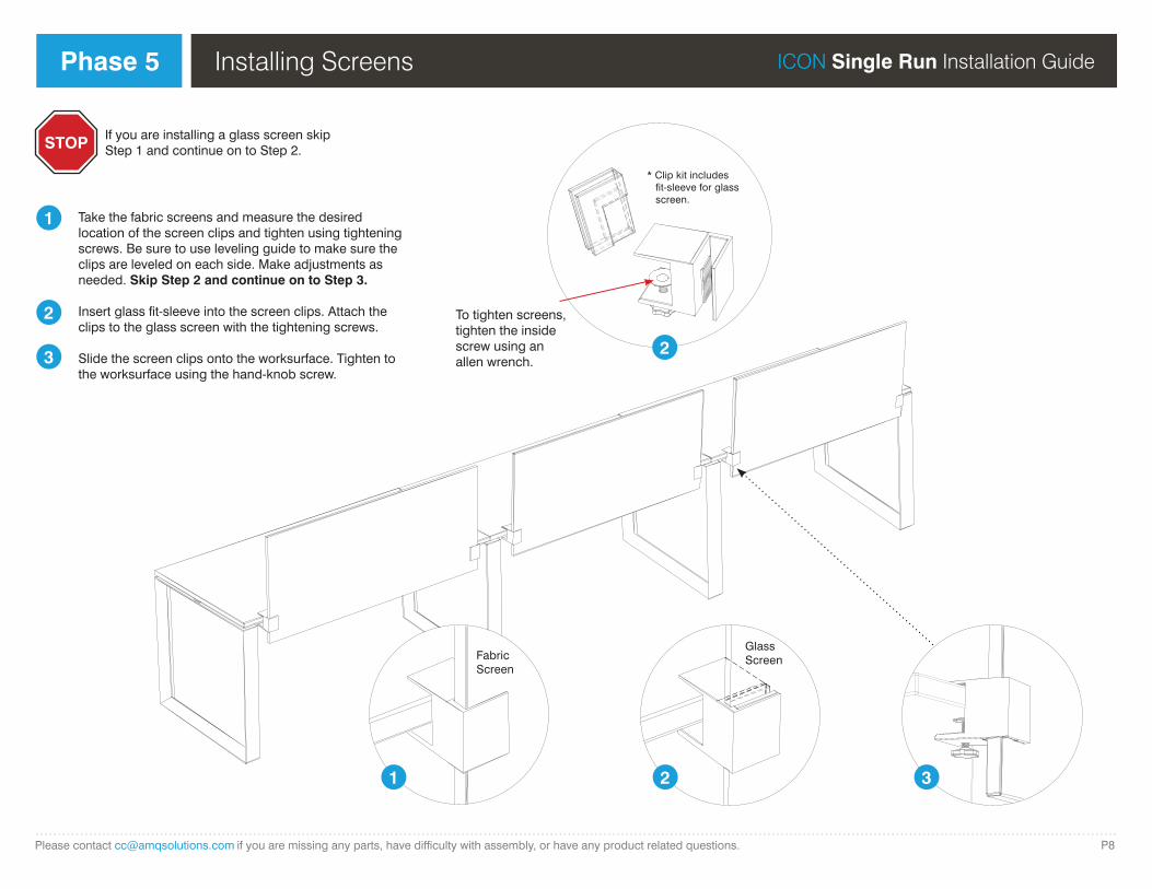
Take the fabric screens and measure the desired location of the screen clips and tighten using tightening screws. Be sure to use leveling guide to make sure the clips are leveled on each side. Make adjustments as needed. Skip Step 2 and continue on to Step 3.
Insert glass fit-sleeve into the screen clips. Attach the clips to the glass screen with the tightening screws.
Slide the screen clips onto the worksurface. Tighten to the worksurface using the hand-knob screw.
STOP If you are installing a glass screen skip Step 1 and continue on to Step 2.
2
To tighten screens, tighten the inside screw using an allen wrench.
....................................................................................................................................................................................................................................................P9Please contact [email protected] if you are missing any parts, have difficulty with assembly, or have any product related questions.
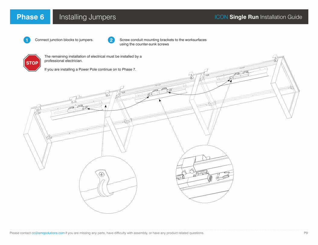
ICON Single Run Installation Guide Installing JumpersPhase 6
The remaining installation of electrical must be installed by a professional electrician.
If you are installing a Power Pole continue on to Phase 7.
STOP
1 2Connect junction blocks to jumpers. Screw conduit mounting brackets to the worksurfaces using the counter-sunk screws

....................................................................................................................................................................................................................................................P10Please contact [email protected] if you are missing any parts, have difficulty with assembly, or have any product related questions.
ICON Single Run Installation Guide Installing a Power PolePhase 7
* Use self-tapping screw for attaching pole to leg beams.
* Use ceiling cover to secure pole to the ceiling.
1
2
4
5
Screw the power pole (pp) brackets to the top and bottom of the O-leg using self-tappers.
Lay your pp on the floor and feed the ceiling feed through the bottom cutout of the pp. Loose wires should be at the top.
Place the ceiling cover on the top of the pp.
Lift the pp up and screw into pp brackets.
Connect jumper to ceiling feed.
Use the ceiling cover to secure pp to the ceiling.
STOP The remaining installation of electrical must be installed by a professional electrician.
Make sure ceiling is prepped for the power pole location. You can use the ceilng cover as a guide to determine how big a cut out you need.
35

Phase 1 Frame Assembly
....................................................................................................................................................................................................................................................P11Please contact [email protected] if you are missing any parts, have difficulty with assembly, or have any product related questions.
ICON Single Run Installation Guide
ICON installation guide DOUBLE RUN
Phase 1
....................................................................................................................................................................................................................................................P12Please contact [email protected] if you are missing any parts, have difficulty with assembly, or have any product related questions.
ICON Double Run Installation Guide
1
1
2
2
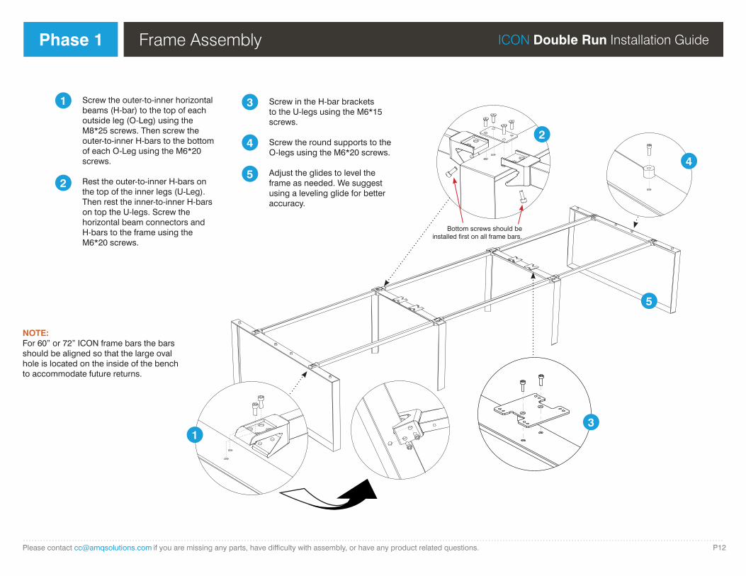
Screw the outer-to-inner horizontal beams (H-bar) to the top of each outside leg (O-Leg) using the M8*25 screws. Then screw the outer-to-inner H-bars to the bottom of each O-Leg using the M6*20 screws.
Rest the outer-to-inner H-bars on the top of the inner legs (U-Leg). Then rest the inner-to-inner H-bars on top the U-legs. Screw the horizontal beam connectors and H-bars to the frame using the M6*20 screws.
3
3
4
54
5
Screw in the H-bar brackets to the U-legs using the M6*15 screws.
Screw the round supports to the O-legs using the M6*20 screws.
Adjust the glides to level the frame as needed. We suggest using a leveling glide for better accuracy.
Frame Assembly
Bottom screws should be installed first on all frame bars.
NOTE: For 60” or 72” ICON frame bars the bars should be aligned so that the large oval hole is located on the inside of the bench to accommodate future returns.
....................................................................................................................................................................................................................................................P13Please contact [email protected] if you are missing any parts, have difficulty with assembly, or have any product related questions.
ICON Double Run Installation Guide Phase 2 Assembling Worksurfaces and Electrical
1
1
2
3
3
4
5
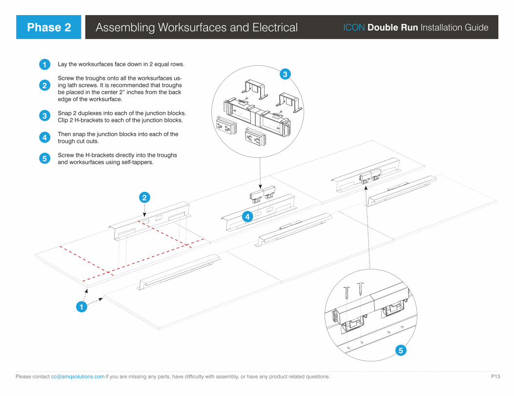
Lay the worksurfaces face down in 2 equal rows.
Screw the troughs onto all the worksurfaces us-ing lath screws. It is recommended that troughs be placed in the center 2” inches from the back edge of the worksurface.
Snap 2 duplexes into each of the junction blocks. Clip 2 H-brackets to each of the junction blocks.
Then snap the junction blocks into each of the trough cut outs.
Screw the H-brackets directly into the troughs and worksurfaces using self-tappers.
2
5
4
....................................................................................................................................................................................................................................................P14Please contact [email protected] if you are missing any parts, have difficulty with assembly, or have any product related questions.
ICON Double Run Installation Guide Phase 3 Attaching Worksurfaces to Frame
1 5
26
3
7
4
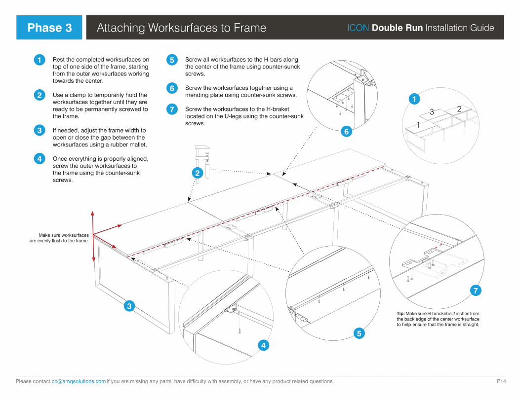
Rest the completed worksurfaces on top of one side of the frame, starting from the outer worksurfaces working towards the center.
Use a clamp to temporarily hold the worksurfaces together until they are ready to be permanently screwed to the frame.
If needed, adjust the frame width to open or close the gap between the worksurfaces using a rubber mallet.
Once everything is properly aligned, screw the outer worksurfaces to the frame using the counter-sunk screws.
Screw all worksurfaces to the H-bars along the center of the frame using counter-sunck screws.
Screw the worksurfaces together using a mending plate using counter-sunk screws.
Screw the worksurfaces to the H-braket located on the U-legs using the counter-sunk screws. 1
23
1
Make sure worksurfaces are evenly flush to the frame.
2
3
4
5
6
7
Tip: Make sure H-bracket is 2 inches from the back edge of the center worksurface to help ensure that the frame is straight.
....................................................................................................................................................................................................................................................P15Please contact [email protected] if you are missing any parts, have difficulty with assembly, or have any product related questions.
ICON Double Run Installation Guide Phase 4 Installing Optional Accessories
1
1
2
2
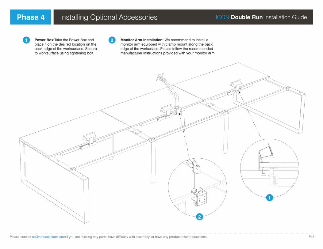
Power Box:Take the Power Box and place it on the desired location on the back edge of the worksurface. Secure to worksurface using tightening bolt.
Monitor Arm Installation: We recommend to install a monitor arm equipped with clamp mount along the back edge of the workurface. Please follow the recommended manufacturer instructions provided with your monitor arm.
....................................................................................................................................................................................................................................................P16Please contact [email protected] if you are missing any parts, have difficulty with assembly, or have any product related questions.
ICON Double Run Installation Guide Phase 5
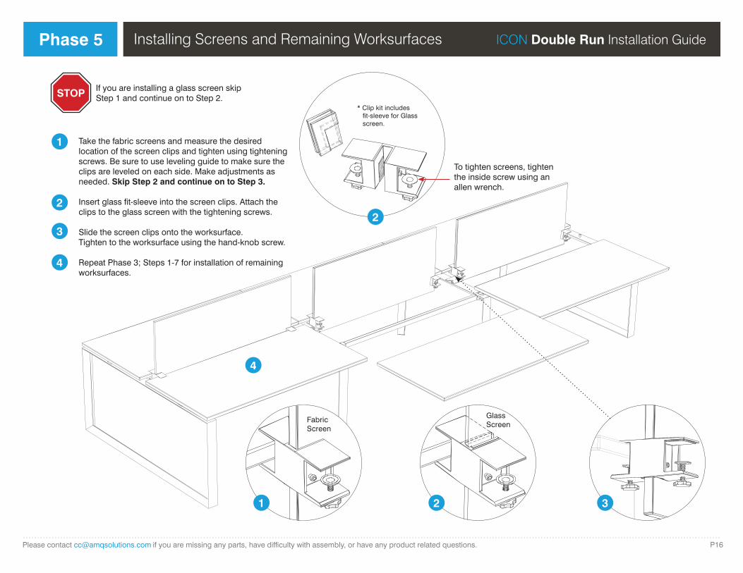
* Clip kit includes fit-sleeve for Glass screen.
FabricScreen
GlassScreen
1 2 3
4
1
2
3
4
Take the fabric screens and measure the desired location of the screen clips and tighten using tightening screws. Be sure to use leveling guide to make sure the clips are leveled on each side. Make adjustments as needed. Skip Step 2 and continue on to Step 3.
Insert glass fit-sleeve into the screen clips. Attach the clips to the glass screen with the tightening screws.
Slide the screen clips onto the worksurface.Tighten to the worksurface using the hand-knob screw.
Repeat Phase 3; Steps 1-7 for installation of remaining worksurfaces.
STOP If you are installing a glass screen skip Step 1 and continue on to Step 2.
2
Installing Screens and Remaining Worksurfaces
To tighten screens, tighten the inside screw using an allen wrench.
....................................................................................................................................................................................................................................................P17Please contact [email protected] if you are missing any parts, have difficulty with assembly, or have any product related questions.
ICON Double Run Installation Guide Phase 6 Installing Jumpers
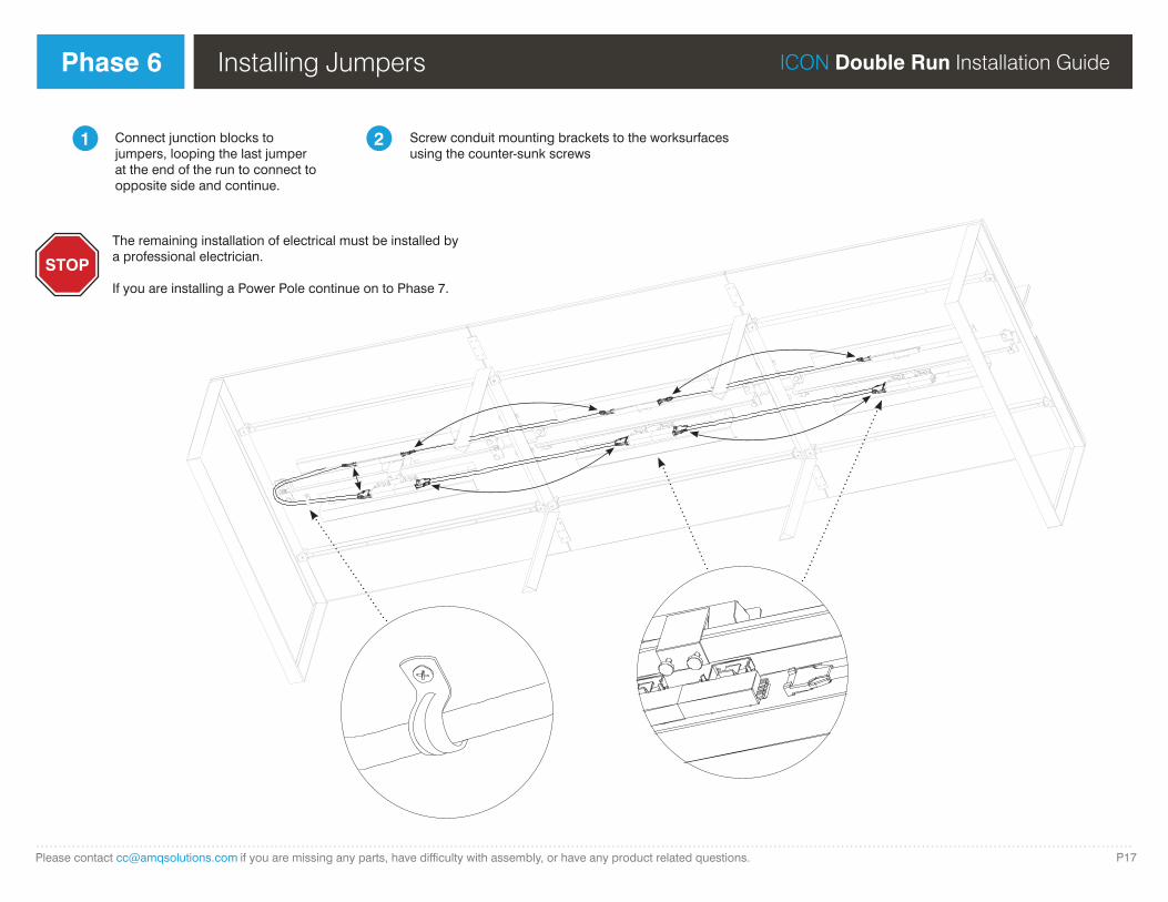
The remaining installation of electrical must be installed by a professional electrician.
If you are installing a Power Pole continue on to Phase 7.
STOP
1 2Connect junction blocks to jumpers, looping the last jumper at the end of the run to connect to opposite side and continue.
Screw conduit mounting brackets to the worksurfaces using the counter-sunk screws
....................................................................................................................................................................................................................................................P18Please contact [email protected] if you are missing any parts, have difficulty with assembly, or have any product related questions.
ICON Double Run Installation Guide Phase 7 Installing a Power Pole
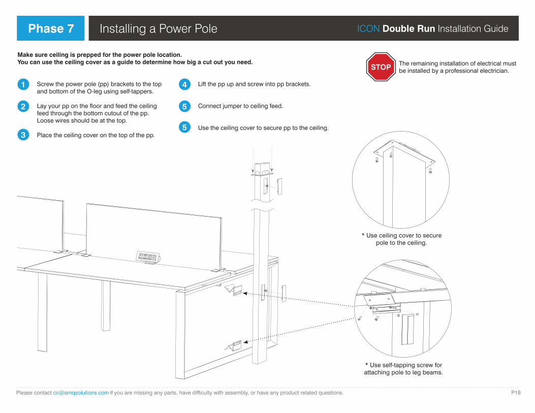
* Use self-tapping screw for attaching pole to leg beams.
* Use ceiling cover to secure pole to the ceiling.
1
2
4
5
Screw the power pole (pp) brackets to the top and bottom of the O-leg using self-tappers.
Lay your pp on the floor and feed the ceiling feed through the bottom cutout of the pp. Loose wires should be at the top.
Place the ceiling cover on the top of the pp.
Lift the pp up and screw into pp brackets.
Connect jumper to ceiling feed.
Use the ceiling cover to secure pp to the ceiling.
STOP The remaining installation of electrical must be installed by a professional electrician.
Make sure ceiling is prepped for the power pole location. You can use the ceiling cover as a guide to determine how big a cut out you need.
35

Phase 1
....................................................................................................................................................................................................................................................P19Please contact [email protected] if you are missing any parts, have difficulty with assembly, or have any product related questions.
ICON Modesty Panel Installation Guide
1
2
3
Locate the four pilot holes on the board and attach four brackets using M5 wood screws.
Place the assembly from previous step inside the leg’s opened profile.
Using M4 self-tapping screws, attach the assembly onto the leg frame.
1. Locate the four pilot holes on the board and attach four brackets using M5 wood screws.2. Place the assembly from previous step inside of the leg’s opened profile3. Using M4 self-tapping screws, attach the assembly onto the leg frame.
Connector x 4 pcs
M4x20 Self tapping screw x 4
M5x12 Wood screw x 4
Isle Side
Leg side

915 Walsh Avenue / Santa Clara, CA 95050 (877) 801-0370 amqsolutions.com
5 Day Open Plan we provide exceptional experiences with reliable, easy interactions and successfully fulfilled orders in only 5 days
Related Documents