Application and Installation Guide for Generator Sets from Cummins Power Generation Power Generation

Installation for Generator Set
Jan 19, 2016
Welcome message from author
This document is posted to help you gain knowledge. Please leave a comment to let me know what you think about it! Share it to your friends and learn new things together.
Transcript

Application and InstallationGuide for Generator Sets
from Cummins Power Generation
PowerGeneration


INDEX
Section AStandards
Regulations
World supplies
Formulae
Installation questionnaire
Section BFoundations and recommended room sizes and
layouts for one to four generators with or without
sound attenuation
Section CFuel systems
Exhaust systems
Cooling systems
Starting systems
Section DControl systems
Paralleling
Switchgear
Cabling
Earthing
Circuit breakers
Automatic transfer systems
Section EHealth & Safety
Motor starting
Section FSoundproofing
Silenced sets
Dimensions and weights
Section GTechnical data on gen sets
Air flows
Exhaust flows
Fuel consumption
Dimensions and weights
Conversion tables
Full load current tables


GENERAL Section A
A1
ScopeThis manual provides an Installation Guide for CumminsPower Generation generator sets. This includes thefollowing information:-
Room Sizes Mounting Recommendations Electrical Connections Mechanical Connections Health and Safety General Maintenance Silencing Technical Data
This manual details typical installations only as it is notpossible to give specific details to many variables in anapplication.
If you should require any further advice or information,please consult:
Cummins Power Generation Ltd
Manston Park
Columbus Avenue, Manston
Ramsgate
Kent CT12 5BF, UK
Tel : +44 (0) 1843 255000
Fax : +44 (0) 1843 255902
Regulations and BibliographyThe authorities listed below may provide informativesources when planning and implementing an installation.
Electrical Installation
Electrical Supply Regulations - 1937
“For securing the safety of the public and for ensuringa proper and sufficient supply of electrical energy”
Electricity (Supply) Acts 1882 1936
Her Majesty’s Stationary Office (H.M.S.O)
Distribution units for electricity supplies forconstruction and building sites.
British Standard (BS) 4363
Regulations for the Electrical Equipment of Buildings.
Institute of Electrical Engineers (1966)
Electrical Installations - General
British Standard Code of Practice CP321
Private Electric Generating Plant CP323
Quality Assessment Schedule QAS/3420.121 relating toBS5750 Part 1 will apply.
ABGSM Publication TM3 (Revised 1985)
“Code of Practice for Designers, Installers and Usersof Generating Sets.”
Asbestos (Licensing) Regulations 1983 (SI 1983 No1649) and Health and Safety at Work series Booklet H5(R) 19
A Guide to Asbestos (Licensing ) Regulations 1983.
Electricity Council Engineering Recommendations G5/3and G59.
Factories Act 1961
Health and Safety at Work Act 1974
ISO 4782 - Measurement of Airborne noise emitted byconstruction equipment for outdoor use - method ofchecking for compliance.
BS 4142 ISO 1996 - Method of rating industrial noiseaffecting mixed residential and industrial areas.
Electrical Equipment
The Electrical Performance of Rotating ElectricalMachinery BS2615
Electrical Protective Systems for A.C Plant BS3950
A useful glossary of British Standards applicable toelectrical components is given at the ‘ Sectional List ofBritish Standards Institution.’
IEC 479 Effects of Current Passing through the HumanBody
IEE Regulations (15th Edition)
BS 159 1957 - Busbars and Busbar Connections.
BS 162 1661 - Electrical Power Switchgear andAssociated Apparatus.
BS 2757 Insulation
BS 4999 - General requirements for Rotating ElectricalMachines.
BS 5000 Part 3 1980 - Generators to be driven byreciprocating Internal Combustion Engines.
BS 5424 Part 1 1977 - Contractors.
BS 5486 (IEC 439) - Factory Built assemblies of LowVoltage Switchgear and Control Gear.
Mechanical Equipment
BS 1649 - Guards for Shaft Couplings
BS529 - Steel Eye Bolts
EEC Directive 84/536/EEC - Noise from constructionequipment - power generators.
BS 476 Part 7 Class 1 - Surface spread of Flame Testsof Materials.
BS 799 Part 5 - Oil Storage Tanks
BS 2869 1970 - Fuel Oils for Oil Engines and Burners fornon- marine use.
BS 3926 - Recommendations for the use of maintenanceof Engine Coolant Solutions.
BS 4675 Part 1 (ISO 2372) - Mechanical vibration inreciprocating machinery.

GENERAL Section A
A2
BS 4959 - Recommendations for Corrosion and ScalePrevention in Engine Cooling Water Systems.
BS 5117 - Methods of Test for Corrosion InhibitionPerformance of Anti-Freeze Solutions.
BS 5514 (ISO 3046) - Specification for ReciprocatingInternal Combustion Engines, Part 1 to 6.
Manufacturing and Design Standards
The generator and its control system are manufacturedunder a registered quality control system approved to BSEN ISO 9001 (1994). The following regulations areobserved where applicable:
The Health & Safety at work Act 1974.
The Control of Substances Hazardous to Health Act1974, 1988 & 1989.
IEE Wiring Regulations for Electrical Installations(16th Edition).
The Electricity at Work Regulations 1989.
The Environmental Protection Act 1990.
The Health & Safety at work Regulations 1992.
The EMC Directive 89/336/EEC.
The LV Directive 73/23/EEC.
The Machinery Directive 89/392/EEC.
The generator and its control system has beendesigned, constructed and tested generally inaccordance with the following Standards whereapplicable: BS 4999 General requirements for rotating
(IEC 341) electrical machines. BS 5000 Rotating electrical machines of
(IEC 341) particular types or for particularapplications.
BS 5514 Reciprocating internal combustion (ISO 30462) engines: performance.
BS 7671 Requirements for electrical (IEC 3641) installations. IEE Wiring Regulations
(sixteenth edition). BS 7698 Reciprocating internal combustion
(ISO 85282) engine driven alternating currentgenerating sets.
BS EN 50081 Electromagnetic compatibility. Generic (EN 500812) emission standard.
BS EN 50082 Electromagnetic compatibility. Generic (EN 500822) immunity standard.
BS EN 60439 Specification for low-voltage (IEC 4391) switchgear and control gear(EN 604392) assemblies.
BS EN 60947 Specification for low voltage (IEC 9471) switchgear and control gear.(EN 609472)
KEY:1 A related, but not equivalent, standard: A BSI
publication, the content of which to any extent at all,short of complete identity or technical equivalence,covers subject matters similar to that covered by acorresponding international standard.
2 An identical standard: A BSI publication identical inevery detail with a corresponding internationalstandard.
Regulations Governing Installations
Before purchasing a generating set, the advice of thelocal authority should be obtained with regard to thefollowing requirements:-
Planning permission for the generator building.
Regulations governing the following:-
Storage of fuel
Noise levels
Air pollution levels
Electrical earthing requirements
Failure to comply with the local authorities regulations,may result in the generator not being used. This type ofpurchase should be installed correctly using the “best”materials and installation guides to ensure the generatorset lasts a lifetime.
Specialist advice should be sought concerning any partof the building requirements, installation, commissioningetc. or any references in this manual from CumminsPower Generation Applications Engineering Group.
Data compiled in this manual will be continuouslyimproved and therefore subject to change without notice,all rights are reserved.

GENERAL Section A
A3
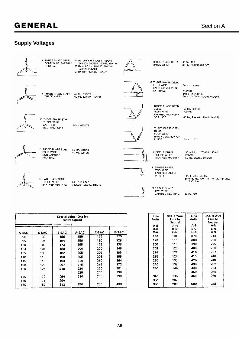
Country Frequency Supply Voltage(Hz) Levels in Common
Use (V)
Abu Dhabi (United Arab Emirates) 50 415/250
Afghanistan 50; 60 380/220; 220
Algeria 50 10 kV; 5.5 kV; 380/220; 220/127
Angola 50 380/220; 220
Antigua 60 400/230; 230
Argentina 50 13.2 kV; 6.88 kV; 390/225; 339/220: 220
Australia 50 22 kV; 11 kV; 6.6 kV; 440/250; 415/240; 240
Austria 50 20 kV; 10 kV; 5 kV; 380/220; 220
Bahamas 60 415/240; 240/120; 208/120; 120
Bahrain 50: 60 11 kV; 400/230: 380/220; 230; 220/110
Bangladesh 50 11 kV; 400/230; 230
Barbados 50 11 kV; 3.3 kV; 230/115; 200/115
Belgium 50 15 kV; 6 kV; 380/220; 2201127, 220
Belize 60 440/220; 220/110
Bermuda 60 4.16/2.4 kV; 240/120; 208/120
Bolivia 50; 60 230/115; 400/230/220/110
Botswana 50 380/220: 220
Brazil 50; 60 13.8 kV; 11.2 kV: 380/220,220/127
Brunei 50 415/230
Bulgaria 50 20 kV; 15 kV; 380/220; 220
Burma 50 11 kV; 6.6 kV; 400/230; 230
Burundi
Cambodia 50 380/220; 208/120; (Khmer Republic) 120
Cameroon 50 15 kV; 320/220; 220
Canada 60 12.5/7.2 kV; 600/347; 240/120; 208/120; 600; 480; 240
Canary Islands 50 380/220; 230
Cape Verde Islands 50 380/220; 127/220
Cayman Islands 60 480/240; 480/227; 240/120; 208/120
Central African Republic 50 380/220
Chad 50 380/220; 220
China 50 380/220 50Hz
Chile 50 380/220; 220
Colombia 60 13.2 kV; 240/120; 120
Costa Rica 60 240/120; 120
World Electricity Supplies
Country Frequency Supply Voltage(Hz) Levels in Common
Use (V)
Cuba 60 440/220; 220/110
Cyprus 50 11 kV; 415/240; 240
Czechoslovakia 50 22 kV; 15 kV; 6 kV; 3 kV; 380/220; 220
Dahomey 50 15 kV; 380/220; 220
Denmark 50 30 kV; 10 kV; 380/220; 220
Dominica (Windward Islands) 50 400/230
Dominican Republic 60 220/110; 110
Dubai (United Arab 50 6.6 kV; 330/220;Emirates) 220
Ecuador 60 240/120; 208/120; 220/127; 220/110
Egypt (United Arab 50 11 kV; 6.6 kV; Republic) 380/220; 220
Eire (Republic of Ireland) 50 10 kV; 380/220; 220
El Salvador 60 14.4 kV; 2.4 kV; 240/120
Ethiopia 50 380/220; 220
Faeroe Islands (Denmark) 50 380/220
Falkland Islands (UK) 50 415/230; 230
Fiji 50 11 kV; 415/240; 240
Finland 50 660/380; 500; 380/220; 220
France 50 20 kV; 15 kV; 380/220; 380; 220; 127
French Guiana 50 380/220
French Polynesia 60 220; 100
Gabon 50 380/220
Gambia 50 400/230; 230
Germany (BRD) 50 20 kV; 10 kV; 6 kV; 380/220; 220
Germany (DDR) 50 10 kV; 6 kV; 660/380; 380/220; 220/127; 220; 127
Ghana 50 440/250; 250
Gibraltar 50 415/240
Greece 50 22 kV; 20 kV; 15 kV; 6.6 kV; 380/220
Greenland 50 380/220
Grenada (Windward 50 400/230; 230Islands)
Guadeloupe 50; 60 20 kV; 380/220; 220
Guam (Mariana Islands) 60 13.8 kV; 4 kV; 480/277; 480: 240/120; 207/120
Guatemala 60 13.8 kV; 240/120
Guyana 50 220/110
Haiti 60 380/220; 230/115; 230; 220; 115
Country Frequency Supply Voltage(Hz) Levels in Common
Use (V)
Honduras 60 220/110; 110
Hong Kong (and Kowloon) 50 11 kV; 346/200; 200
Hungary 50 20 kV; 10 kV; 380/220; 220
Iceland 50 380/220; 220
India 50; 25 22 kV; 11 kV; 440/250; 400/230; 460/230; 230
Indonesia 50 380/220; 2201127
Iran 50 20 kV; 11 kV; 400/231; 380/220; 220
Iraq 50 11 kV; 380/220; 220
Israel 50 22 kV; 12.6 kV; 6.3 kV; 400/230; 230
Italy 50 20 kV; 15 kV; 10 kV; 380/220; 220/127; 220
Ivory Coast 50 380/220; 220
Jamaica 50 4/2.3 kV; 220/110
Japan 50; 60 6.6 kV; 200/100; 22 kV; 6.6 kV; 210/105; 200/100; 100
Jordan 50 380/220; 220
Kenya 50 415/240; 240
Korea Republic (South) 60 200/100; 100
Kuwait 50 415/240; 240
Laos 50 380/220
Lebanon 50 380/220; 190/110; 220;110
Lesotho 50 380/220; 220
Liberia 60 12.5/7.2 kV; 416/240; 240/120; 208/120
Libyan Arab Republic 50 400/230; 220/127; 230;127
Luxembourg 50 20 kV; 15 kV; 380/220; 220
Macao 50 380/220; 220/110
Malagassy Republic 50 5 kV; 380/220; (Madagascar) 220/127
Malawi 50 400/230; 230
Malaysia (West) 50 415/240; 240
Mali 50 380/220; 220/127; 220; 127
Malta 50 415/240
Manila 60 20 kV; 6.24 kV; 3.6 kV; 240/120
Martinique 50 220/127; 127
Mauritania 50 380/220
Mauritius 50 400/230; 230
Mexico 60 13.8 kV; 13.2 kV; 480/277; 220/127; 220/120
Monaco 50 380/220; 220/127; 220; 127

GENERAL Section A
A4
World Electricity Supplies
Country Frequency Supply Voltage(Hz) Levels in Common
Use (V)
Montserrat 60 400/230; 230
Morocco 50 380/220; 220/127
Mozambique 50 380/220
Muscat and Oman 50 415/240; 240
Naura 50 415/240
Nepal 50 11 kV; 400/220; 220
Netherlands 50 10 kV; 3 kV; 380/220; 220
Netherlands Antilles 50; 60 380/220; 230/115; 220/127; 208/120
New Caledonia 50 220
New Zealand 50 11 kV; 415/240; 400/230; 440; 240; 230
Nicaragua 60 13.2 kV; 7.6 kV; 240/120
Niger 50 380/220; 220
Nigeria 50 15 kV; 11 kV; 400/230; 380/220; 230; 220
Norway 50 20 kV; 10 kV; 5 kV; 380/220; 230
Pakistan 50 400/230; 230
Panama 60 12 kV; 480/227; 240/120; 208/120
Papua New Guinea 50 22 kV; 11 kV; 415/240; 240
Paraguay 50 440/220; 380/220; 220
Peru 60 10 kV; 6 kV; 225
Philippines 60 13.8 kV; 4.16 kV; 2.4 kV; 220/110
Poland 50 15 kV; 6 kV; 380/220; 220
Portugal 50 15 kV; 5 kV; 380/220; 220
Portuguese Guinea 50 380/220
Puerto Rico 60 8.32 kV; 4.16 kV; 480; 240/120
Qatar 50 415/240; 240
Reunion 50 110/220
Romania 50 20 kV; 10 kV; 6 kV; 380/220; 220
Rwanda 50 15 kV; 6.6 kV; 380/220; 220
Country Frequency Supply Voltage(Hz) Levels in Common
Use (V)
Sabah 50 415/240; 240
Sarawak (East Malaysia) 50 4151240; 240
Saudi Arabia 60 380/220; 220/127; 127
Senegal 50 220/127; 127
Seychelles 50 415/240
Sierra Leone 50 11 kV; 400/230; 230
Singapore 50 22 kV; 6.6 kV; 400/230; 230
Somali Republic 50 440/220; 220/110; 230: 220; 110
South Africa 50; 25 11 kV; 6.6 kV; 3.3 kV; 433/250; 400/230; 380/220; 500; 220
Southern Yemen (Aden) 50 400/230
Spain 50 15 kV; 11 kV; 380/220; 220/127; 220; 127
Spanish Sahara 50 380/220; 110; 127
Sri Lanka (Ceylon) 50 11 kV; 400/230; 230
St. Helena 50 11 kV; 415/240
St. Kitts Nevis Anguilla 50 400/230; 230
St. Lucia 50 11 kV; 415/240; 240
Saint Vincent 50 3.3 kV; 400/230; 230
Sudan 50 415/240; 240
Surinam 50; 60 230/115; 220/127; 220/110; 127; 115
Swaziland 50 11 kV; 400/230; 230
Sweden 50 20 kV; 10 kV; 6 kV; 380/220; 220
Switzerland 50 16 kV; 11 kV; 6 kV; 380/220; 220
Syrian Arab Republic 50 380/220; 200/115; 220; 115
Taiwan (Republic of China) 60 22.8 kV; 11.4 kV; 380/220; 220/110
Tanzania (Union 50 11 kV; 400/230Republic of)
Thailand 50 380/220; 220
Country Frequency Supply Voltage(Hz) Levels in Common
Use (V)
Togo 50 20 kV; 5.5 kV; 380/220; 220
Tonga 50 11 kV; 6.6 kV; 415/240; 240; 210
Trinidad and Tobago 60 12 kV; 400/230; 230/115
Tunisia 50 15 kV; 10 kV; 380/220; 220
Turkey 50 15 kV; 6.3 kV; 380/220; 220
Uganda 50 11 kV; 415/240; 240
United Kingdom 50 22 kV; 11 kV; 6.6 kV; 3.3 kV; 400/230; 380/220; 240; 230; 220
Upper-Yolta 50 380/220; 220
Uruguay 50 15 kV; 6 kV; 220
USA 60 480/277; 208/120; 240/120
USSR 50 380/230; 220/127 and higher voltages
Venezuela 60 13.8 kV; 12.47 kV; 4.8 kV; 4.16 kV; 2.4 kV; 240/120; 208/120
Vietnam (Republic of) 50 15 kV; 380/220; 208/120; 220; 120
Virgin Islands (UK) 60 208; 120
Virgin Islands (US) 60 110/220
Western Samoa 50 415/240
Yemen, Democratic (PDR) 50 440/250; 250
Yugoslavia 50 10 kV; 6.6 kV; 380/220; 220
Zaire (Republic of) 50 380/220; 220
Zambia 50 400/230; 230
Zimbabwe 50 11 kV; 390/225; 225
Table 1 World Electricity Supplies
GENERAL Section A
A5
Supply Voltages

GENERAL Section A
A6
Equivalents and FormulaeEquivalents1 horsepower = 746watts 1 kW = 1 000watts1 horsepower = 0.746kW 1 kW = 1.3415hp1 horsepower = 33,000ft lb/min 1 kW = 56.8ft lb/min
ft lb/min1 horsepower = 550ft lb/sec 1 kW = 738ft lb/sec1 horsepower = 2546Btu/hr 1 kW = 3412Btu/hr1 horsepower = 42.4Btu/min
1 Btu = 9340in lb1 Btu = 778.3ft lb 1ft lb = 0.001284Btu1 Btu =.0002930kWhr 1 kWhr = 3413Btu1 Btu = 1.05506kJ
1 Btu/min = 17.57watts1 Btu/min = 0.0176kW1 Btu/min = 0.0236hp1 Btu/hr = 0.293watts
1 ft lb = 1.35582Nm1 ft lb/sec = 0.001355kW1 ft lb/sec = 0.001818hp
1 therm = 100,000Btu 12,000Btu = 1 Ton (air conditioning)
Formulae
Brake Mean Effective Pressure (BMEP)
792,000 x BHPBMEP = ——————————————— (for 4-cycle)
rpm x cubic inch displacement
Brake Horsepower (BHP)
BMEP x cubic inch displacement x rpmBHP = ———————————————— (for 4-cycle)
792,000
Torque
5250 x BHPTorque (ft lb) = —————————
rpm
Temperature
(°F - 32)Temp. (°C) = ————————— °F = (°C x 1.8) + 32
1.8
Power Factor & kVA
kW kWPF = ———— KVA = ————
kVA PF
Formulae for Obtaining kW, kVA, Reactive kVA, BHPand Amperes
To Obtain:
Single Phase AC Three Phase AC Direct Current
V x A x PF kVA x PF V x AKW = ———— ———— ————
1000 1000 1000
V x A V x A x 1.732KVA = ———— ——————
1000 1000
Reactive kVA = kVA x 1 - PF2 kVA x 1 - PF2
BHP (Output) = V x A x Gen. Eff. X PF 1.73 x V x A x Eff. X PF V x A x Gen. Eff. ———————— ————————— ——————
746 x 1000 746 x 1000 746 x 1000
BHP (Input) = kW kW
—————— ——————746 x 1000 746 x 1000
A (when BHP is known) =BHP x 746 x 100 BHP x 746 x 100 BHP x 746 x 100——————— ————————— —————V x Gen. Eff. x PF 1.73 x V x Gen. Eff. x PF V x Gen. Eff.
A (when kW is known) =KW x 1000 kW x 1000 kW x 1000
——————— ——————— ———————V x PF V x PF x 1.732 V
A (when KVA is known) =KVA x 1000 KVA x 1000
——————— ———————V V x 1.732
Misc.
No. of poles x RPM No. of poles x RPMHZ = —————————— ——————————
120 120
KW KWHP = —————————— ——————————
0.746 x Gen Efficiency 0.746 x Gen Efficiency
Where;-kW = KilowattsV = Line to Line VoltageA = Line CurrentPF = Power FactorHZ = FrequencyHP = Horse Power

INSTALLATION QUESTIONNAIRE Section A
A7
Special Access Requirements:..........................................................
..........................................................................................................
Radiator 40°C 50°C
Is radiator to be Integral or REMOTE or OTHER
Position of Remote radiator relative to both plant and
control panel......................................................................................
..........................................................................................................
EXHAUST
Type of flue to be used: Steel Twin wall stainless steel
Overall length of exhaust Horiz ................Vert ..............metres/ft.
Number of Bends ..............................................................................
Type of Silencers: Residential Acoustic Other
Type of Brackets: Roller Fixed Spring
GLC type Mixed
Pipework to be: Flanged Butt welded
Residential Silencer to be:
floor mounted wall mounted ceiling mounted
Acoustic Silencer to be:
floor mounted wall mounted ceiling mounted
Exhaust weathering in: wall roof
Termination in: tailpipe cowl
Finish to pipework: red lead black epoxy paint
Access for erecting pipework:
good bad scaffold required
Welding supply available: YES NO
Type of lagging: rockwool other
Type of cladding:
22 swg aluminium stainless steel other
Length of pipe to be lagged and clad ................................metres/ft.
Type of silencer to be lagged and clad: Residential Acoustic
CABLE
Type of Load Cables:
PVCSWAPVC CSP/EPR Bus bar LSF
Route length of control cables between plant and panel:
..........................................................................................metres/ft.
Type of control cables:
PVCSWAPVC PVC LSF
Route length of control cables between plant and panel:
..........................................................................................metres/ft.
Load and control cable run in:
Trunking On tray Clipped
Load and control cables run overhead:
on wall on floor in trench
Cable entry to panel: top bottom side
Position of LTB: ................................................................................
Other control cables:
Service ............................................................................ metres/ft
Cable Type ...................................................................... metres/ft
Cable Route Length ........................................................ metres/ft
Installation Questionnairefor Generating SetsIn order to accurately estimate the materials, technicalities andcosting for any installation it is essential that all available datarelating to the generator, location and room be itemised anddocumented before contacting the supplier. This service canalternatively be provided by your local Cummins Distributor.
Project ........................................................................................................................................................................................................Customer (End User) ..................................................................................................................................................................................Address of Site ................................................................................................................................................................................................................................................................................................................................................................................................................Consultant ..................................................................................................................................................................................................Address ..........................................................................................................................................................................................................................................................................................................................................................................................................................Telephone No. ..................................................................................Site Drawing No. ..............................................................................Architect ......................................................................................................................................................................................................
GENERATING SETDETAILSModel .......................................... kVA ............................................p.f. ................................................ kW ..............................................Voltage ........................................ Phases........................................Frequency.................................... Engine ........................................Alternator .................................... Control System ..........................Number ........................................ Size of Room ..............................Position of Set(s) ..............................................................................indicate on site drawing if possibleAre Control Panels to be Integral or Free Standing Position of Free Standing Control Panel ....................................................................................................................................................Motor starting YES NO UPS Load YES NO Operate Lifts YES NO Base Fuel Tank YES NO
SITE CONDITIONSBrief description of site working conditions including timescale for installation: ................................................................................................................................................................................
Type of Crane ................................................................................Distance to position of set from roadway? ....................................Type of Transport ..........................................................................Police Involvement YES NO Road Closure YES NO
Access (obstructions, restrictions, etc.)......................................................................................................................................................Is set to be positioned
IN BASEMENT GROUND LEVELMID LEVEL ROOF TOP
Is set to be dismantled YES NOON PLINTHS R.S.J’s FLOOR

INSTALLATION QUESTIONNAIRE Section A
A8
Number of acoustic doors: ................................................................
Type: single double
Antivibration mounts required: YES NO
Acoustic louvres: YES NO
Noise survey required: YES NO
Sound proof enclosure: YES NO
Container Drop over Int fit out
Walk round Close fit EEC style
Paint finish ..........................RAL/BS4800 ........................................
DUCTINGLength of inlet duct: .......................................................... metres/ft.
No. of bends: ..........................................................................
Length of outlet duct: ........................................................ metres/ft.
No. of bends: ..........................................................................
Inlet duct: floor mounted wall mounted off ceiling
Outlet duct: floor mounted wall mounted off ceiling
Fire damper in inlet duct: YES NO
Fire damper in outlet duct: YES NO
LOUVRESInlet louvre Outlet louvre
Type: fixed blade gravity motorised
Position of louvre inlet: external internal
Position of louvre outlet: external internal
Colour finish to louvres: ....................................................................
COMMISSIONDistance from Genset/Conn.............................................. metres/ft.
Load Bank Resistive Reactive
Ground level Roof Other
Weekend working
Out of normal hours
During normal hours
First fill of lub. oil: YES NO ................................litres
First fill of fuel Quantity ................................litres
Anti freeze YES NO
Maintenance contract required:: YES NO
Are civil works required: YES NO
Set Length mm..................................................................................
Width mm..................................................................................
Height mm..................................................................................
Weight Kg ..................................................................................
DRAWINGSPlant Room Builders/Civils Other
COMPILED BY: ................................................................................
DATE: ................................................................................................
WATERPipe route length between remote radiator and engine:............................................................................................metres/ftPipe route length between break tank and radiator:.......................................................................................... metres/ft
Break Tank required: YES NO Pipework to be: screwed welded Pipework to be: galvanised steel
FUELType of bulk tank:
Cylindrical Rectangular Double skinned Bunded Capacity of bulk tank: ........................................................................Standard Bosses Extra Bosses Position of Bulk Tank in relation to set:..............................................(height above or below ground etc.)Access for offloading: ........................................................................Pipe route length between bulk tank and service tank:flow .......................................... return ................................metres/ftLocal Atmosphere Remote Vent Route ....................Pipework: below ground above ground Pipework to be jacketed: YES NO Pipe: Trace heated Denso Type of fillpoint required: Cabinet Valve, cap and chain Pipe route length between bulk tank and fill point: ..............metres/ftFill alarm unit and tank float switch required:
YES NO Pipework: Thickness ..................Single Skin Double Skin If double skin all pipe or specify ..................................................Pipework support/fixing ....................................................................Type of bulk tank contents gauge:Hydrostatic Electronic Mechanical Position of contents gauge: ........................if not in fill point cabinetDistance from bulk tank:.................................................... metres/ft.Service tank: free standing on set Overspill tank required: YES NOIf tank free standing, pipe route length to engine:.......................................................................................... metres/ft.Auto fuel transfer system: YES NO
Duplex YES NO Solenoid valve required: YES NO Position: ............................................................................................If pump positioned away from tank determine position: ..............................................................................................................................Fire valve required: YES NO
MERC: YES NO MKOB SQR BATT PACK
Other alarms required: ......................................................................Dump valve
ATTENUATIONLevel of noise to be obtained ..................................................dB(A) What distance.................................................................... metres/ft.Position of inlet splitter: low level high level Position of outlet splitter: low level high level

LAYOUT CONSIDERATIONS Section B
B1
General In order to start to consider the possible layouts for asite, the following criteria must first be determined:-
The total area available and any restrictions withinthat area (i.e. buried or overhead services).
Any noise constraints. (i.e. the location of offices orresidential property).
The access to the site, initially for delivery andinstallation purposes, but afterwards for the deliveriesof fuel and servicing vehicles, etc.
The ground condition, is it level or sloping?
When installing the equipment within a plant room,consideration must be given to each of the following:-
A forced ventilation system is required for theequipment, which draws sufficient cooling andaspiration air into the room at the back of thealternator and discharges the air from in front of theengine. Dependent upon the layout of the building, itmay be necessary to install additional ductwork toachieve the airflow required.
In order to reduce the heat gain within the plant room,all the elements of the exhaust system will need to befully lagged. Where practical, the silencer and asmuch of the pipework as possible should be outsidethe generator room.
The access into the building, initially for the deliveryand installation of the equipment, and, afterwards forservicing and maintenance of the equipment.
The plant room should be of sufficient size toaccommodate the following items of equipment:
The engine/alternator assembly.
The local fuel tank (if applicable).
The generator control panel including the PCC (iffree standing).
The exhaust system (if internally erected).
The air handling system including any soundattenuating equipment that may be required.
The relative height of the base for the bulk tanks shouldalso be taken into consideration to determine the type offuel transfer system that is to be utilised. The sizes forthe bulk fuel storage tank(s) are dependent on theduration of the storage that is required.
Where possible the equipment should be positioned in amanner such that "cross overs" of the ancillary services,(fuel, water and electrical power/controls) do not occur.
Due consideration should be given to the direction of thenoise sensitive areas so that elements generating noisecan be positioned to restrict any potential problem.(i.e.exhaust outlets).
Modular InstallationIn terms of the external appearance the "drop-over"enclosure system is virtually identical to a containerisedsystem. The principle difference between the twosystems is that in the containerised arrangement thegenerator is mounted on the floor of the module,whereas in the "dropover" arrangement, the generatorlocates directly on the concrete plinth and the enclosuredrops over onto the plinth.
To maintain the advantage of the reduction in site work, itis essential to give careful consideration to thepositioning of the set to optimise the space and tominimise the lengths of any inter-connections.
Off-loading and Positioning theEquipmentPrior to the commencement of the off-loading, using thespecific site and equipment drawings, the positions foreach of the principle items of equipment should becarefully marked out on the plinth/plant room floor.
The order in which various items of equipment are to bepositioned should be determined to ensure that doublelifting is avoided as far as possible.
The appropriate size and type of crane should beconsidered bearing in mind the site conditions and liftingradius. All the necessary lifting chains, spreader beams,strops etc., should be used to off-load and position theequipment.

BASE AND FOUNDATIONS Section B
B2
Note : Special foundations are unnecessary. A level andsufficiently strong concrete floor is adequate.
IntroductionThe responsibility for the design of the foundation(including seismic considerations) should be placed witha civil or structural engineer specialising in this type ofwork.
Major functions of a foundation are to:
Support the total weight of the generating set.
Isolate generator set vibration from surroundingstructures.
To support the structural design, the civil engineer willneed the following details:-
the plant’s operating temperatures (heat transfer frommachines to mass could lead to undesirable tensilestresses).
the overall dimensions of the proposed foundationmass.
the mounting and fixing arrangements of thegenerator bedframe.
Concrete FoundationsThe foundation will require at least seven days betweenpouring the concrete and mounting the generating set tocure. It is also essential that the foundation should belevel, preferably within ± 0.5° of any horizontal plane andshould rest on undisturbed soil.
The following formula may be used to calculate theminimum foundation depth :
kt = ————
d x w x l
t = thickness of foundation in m
k = net weight of set in kg
d = density of concrete (take 2403 kg/m2)
w = width of foundation in (m)
l = length of foundation in (m)
The foundation strength may still vary depending on thesafe bearing capacity of supporting materials and thesoil bearing load of the installation site, thereforereinforced gauge steel wire mesh or reinforcing bars orequivalent may be required to be used.
FoundationsMain Block Materials
1 Part Portland Cement
2 Parts clean sharp sand
4 Parts washed ballast (3/4")
Grouting Mixture
1 Part Portland Cement
2 Parts clean sharp sand
When the water is added, the consistency of the mixtureshould be such that it can be easily poured.
Should a suitable concrete base already exist or it is notconvenient to use rag-bolts, then rawl-bolts or similartype of fixing bolt may be used. This obviates thenecessity of preparing foundation bolt holes as alreadydescribed. However, care should be taken that thecorrect size of masonry drill is used.
Modularised System/Enclosed-SilencedGeneratorsIn the design of the layout for this type of system thesame constraints and guidance for the foundation shouldbe observed, however, as the generator set andenclosure will be located directly onto the plinth, morecare is required in its casting to ensure that it is flat andlevel with a "power float" type finish.
When the generator compartment is in the form of adropover enclosure, it will be necessary to provide aweatherproofing sealing system in the form of anglesection laid on an impervious strip seal. This will also actas a bund to retain fuel, water or oil spillage.
Vibration IsolationEach generator is built as a single module with theengine and alternator coupled together through acoupling chamber with resilient mountings to form oneunit of immense strength and rigidity. This provides bothaccuracy of alignment between the engine and alternatorand damping of engine vibration. Thus heavy concretefoundations normally used to absorb engine vibration arenot necessary and all the generator requires is a levelconcrete floor that will take the distributed weight of theunit.

BASE AND FOUNDATIONS Section B
B3
FoundationThe generator can be placed directly on a level, concretefloor, but where a permanent installation is intended, it isrecommended that the unit is placed on two raisedlongitudinal plinths. This allows for easy access formaintenance and also allows a drip tray to be placedunder the sump to meet fire regulation. Plinths shouldraise the plant 100 to 125mm above floor level, theactual height depending on the type of plant. The plinthsare normally cast in concrete but RSJ's or timber can beused. If either of these two materials are used thebearers should be bolted down with parobolts.
If in any doubt consult a Civil Engineer.
Bolting Down
Parobolts should also be used for anchoring theconcrete plinths when necessary.
Caution: Ensure that the concrete is completely setand hardened before positioning the plant andtightening holding down bolts.
Levelling
A poor foundation may result in unnecessary vibration ofthe plant.
ConnectionsAll piping and electrical connections should be flexible toprevent damage by movement of the plant. Fuel andwater lines, exhaust pipes and conduit can transmitvibrations at long distances.
300 kVA standard generator with base fuel tank in typical plant room.

ROOM DESIGN GUIDANCE NOTES Section B
B4
Generator installations with acoustictreatment to achieve 85dBA at 1 metreNote:- The layout drawings provided are intended as aguide and to form the basis of the installation design, butbefore the room design is finalised please ensure youhave a "project specific" generator general arrangementdrawing. Certain ambient temperatures or specific siterequirements can affect the finalised generator build,layout configuration and room dimensions.
Room size allowance
The dimensions as indicated A & B allow for goodmaintenance/escape access around the generator.Ideally you should allow a minimum distance of 1 metrefrom any wall, tank or panel within the room.
Machine access
It is important to remember that the generator has to bemoved into the constructed generator room, thereforethe personnel access door has to be of a sufficient sizeto allow access alternatively the inlet/outlet attenuatoraperture should be extended to the finished floor level,with the bottom uplift section built when the generator isin the room.
Inlet and outlet attenuators with weather louvres
The inlet and outlet attenuators should be installed withina wooden frame and are based on 100mm. airways with200mm. acoustic modules. The attenuators should befitted with weather louvres with a minimum 50% freearea, good airflow profile and afford low restrictionairflow access. The noise level of 85dB(A) at 1m willcomply with minimum EEC Regulations. To achievelower levels attenuator size can more than double inlength.
The weather louvres should have bird/vermin meshscreens fitted on the inside, but these screens must notimpede the free flow of cooling and aspiration air.
The outlet attenuator should be connected to the radiatorducting flange with a heat and oil resistant flexibleconnection.
Exhaust systems
The exhaust systems shown on the layout drawings aresupported from the ceiling. Should the buildingconstruction be such that the roof supports were unableto support the exhaust system, a floor standing steelexhaust stand will be needed. Exhaust pipes shouldterminate at least 2.3m above floor level to make itreasonably safe for anyone passing or accidentallytouching.
It is recommended that stainless steel bellows be fittedto the engine exhaust manifold followed by rigidpipework to the silencer.
The dimension "E" as indicated on the layout diagrams isbased upon using standard manufacturers silencers toachieve 85dBA at 1m, please ensure that the intendedsilencers to be used can be positioned as indicated asthis dimension affects the builders works such asapertures to the walls for the exhaust outlet.
The exhaust run as indicated exits via the side wallthrough a wall sleeve, packed with a heat resistantmedium and closed to the weather with wall plates.
Should the generator room, internally or externally, beconstructed with plastic coated profiled steel sheetcladding, it is important to ensure that the wall sectionsat the exhaust outlet are isolated from the high exhaustpipe temperature and sealed by a specialist cladder. Thesame applies for any exhaust going through or near anytimber or plastic guttering.
It is good installation practice for the exhaust systemwithin the generator room to be insulated with aminimum of 50mm. of high density, high temperaturemineral insulation covered by an aluminium overclad.
This reduces the possibility of operator burn injury andreduces the heat being radiated to the operatinggenerator room.
Cable systems
The layout drawings assumes that the change-overswitch-gear is external to the generator room andlocated in the power distribution room. Specific projectrequirements can affect this layout.
The power output cables from the generator outputbreaker to the distribution panel must be of a flexibleconstruction:-
EPR/CSP (6381TQ)
PCP (H07RNF)
Should the cable route length from the generator to thedistribution room be extensive the flexible cables can beterminated to a load terminal close box to the generatorand then extended to the distribution room witharmoured multi-core cables. (See typical load terminalbox layout).
The flexible power cables as installed should be laid upin trefoil, placed on support trays/ladder rack in thetrench with the recommended inter-spacing andsegregated from the system control cables.
The cables should be correctly supported and rated forthe installation/ambient conditions.
The flexible single core power cables when entering anypanel must pass through a non ferrous gland plate.

Doors.Doors should always open outwards. This not onlymakes for a better door seal when the set/s are runningbut allows for a quick exit/panic button or handle to getout. Make allowance for the generator to be moved intothe room by using double doors at the attenuator space.
Generator installations WITHOUTacoustic treatment.Note: Handy rule of thumb for INTAKE louvres. Use 1.5 xradiator area.All the previous notes regarding "generator installationswith acoustic treatment" equally apply to installationswithout acoustic attenuators with the exception ofparagraph 3 relating to the Inlet and Outlet louvres.
Inlet and outlet louvres.The inlet and outlet weather louvres should be installedwithin a wooden frame with a minimum 50% free area,good airflow profile and low restriction airflow access.The weather louvres should have bird/vermin meshscreens fitted on the inside, but must not impede the freeflow of cooling and aspiration air.The outlet weather louvre should be connected to theradiator ducting flange with a heat and oil resistantflexible connection.
ROOM DESIGN GUIDANCE NOTES Section B
B5
Change-over panels.Should the change-over panel be positioned within thegenerator room due note must be made of the floor/wallspace that must be made available.For change-over cubicles up to 1000Amp. rating the wallmounting panel of maximum depth 420mm. can bemounted directly above the cable trench in the sideaccess area without causing too many problems.For change-over cubicles from 1600Amp. and above, afloor standing panel is used which needs additionalspace to be allocated. Refer to Page D11 for dimensions.The room dimensions need to be increased in the areaof the cable duct/change-over panel to allow space andman access around cubicles with the followingdimensions. A minimum of 800mm. for rear accessshould be allowed.The cable trench in the area of the change-over cubicleneeds to be increased in size to allow for the mains, loadand generator cable access requirement.
Generator Sets.All generators shown include 8 hour base fuel tanks.Free standing tanks can be provided but additional roomspace will be required. Canvas ducting between the radiator and ductwork orattenuator should be a minimum of 300mm.Air inlet should be at the rear of the alternator to allowadequate circulation.
Fig. B1 Cable Connections
Control panel
Note:If flexible cable is usedbetween switchboard, remote panel and generator, a load terminal box is un-neccessary
Multicores run betweenset and DMC cubicle
Flexible cable should be used
Alternatorterminal box
Load terminal box must be usedif connecting cable is PVC/SWA/PVC
DMC
To changeoverswitchboard
When a radiator is mounted on the end of theplant main frame, position the set so that theradiator is as close to the outlet vent as possible,otherwise recirculation of hot air can take place.The recommended maximum distance away fromthe outlet vent is 150mm without air ducting.

RECOMMENDED ROOM SIZES Section B
B6
Prime Type Room dimensions Set Set C/L Exhaust Outlet Inlet
Rating of 2000 1999 Length width height back position Offset Height Louvre Uplift Louvre Cable trench position
KVA ENGINE Model Model A B C D P E X F G H J K L M N
32.5 B3.3G1 26 DGGC CP30-5 3100 3000 2600 400 1500 159 2300 650 700 650 750 800 420 400 1165
50 B3.3G2 40 DGHC CP50-5 3100 3000 2600 400 1500 275 2300 750 800 650 900 900 420 400 1165
38 4B3.9G 30 DGBC CP40-5 3100 3000 2600 400 1500 141 2300 650 750 600 750 850 520 400 1325
52 4BT3.9G1 42 DGCA CP50-5 3200 3000 2600 400 1500 194 2300 650 750 600 750 850 520 400 1325
64 4BT3.9G2 51 DGCB CP60-5 3200 3000 2600 400 1500 194 2300 650 750 600 750 850 520 400 1325
70 4BTA3.9G1 56 DGCC CP70-5 3250 3000 2600 400 1500 194 2300 650 750 600 750 850 520 400 1410
96 6BT5.9G2 77 DGDB CP90-5 3500 3000 2600 400 1500 168 2300 700 860 540 800 800 520 400 1630
106 6BT5.9G2 85 DGDF CP100-5 3500 3000 2600 400 1500 168 2300 700 860 540 800 800 520 400 1630
129 6CT8.3G2 103 DGEA CP125-5 3850 3000 2700 400 1500 255 2300 850 1025 600 1000 1150 520 400 1910
153 6CTA8.3G 122 DGFA CP150-5 3850 3000 2700 400 1500 255 2300 850 1025 600 1000 1150 520 400 1910
185 6CTA8.3G 148 DGFB CP180-5 3850 3000 2700 400 1500 255 2300 850 1025 600 1000 1150 520 400 2070
200 6CTAA8.3G 163 DGFC CP200-5 3950 3000 2700 400 1500 255 2300 850 1025 600 1000 1150 520 400 2070
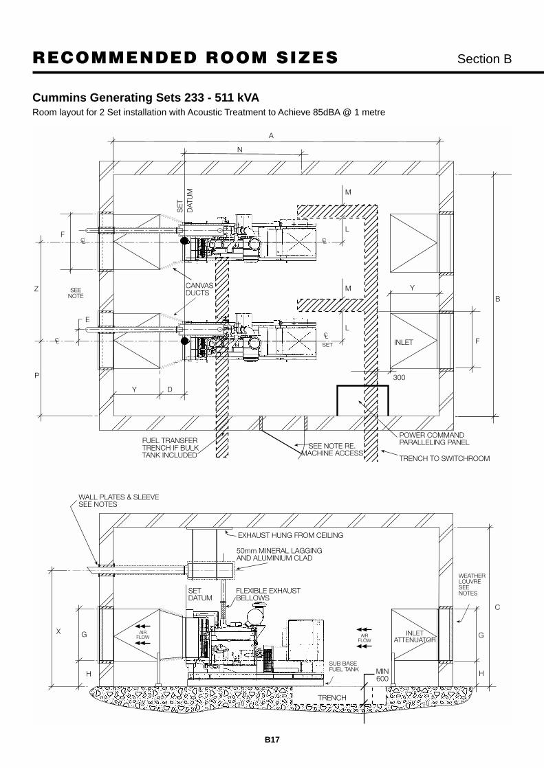
233 LTA10G2 186 DFAB CP200-5 4850 3250 2800 500 1625 361 2300 1000 1075 520 1150 1250 625 400 2285
252 LTA10G3 202 DFAC CP250-5 4850 3250 2800 500 1625 361 2300 1000 1075 520 1150 1250 625 400 2285
315 NT855G6 252 DFBH CP300-5 4850 3200 2700 500 1600 284 2300 1000 1300 700 1250 1400 625 400 2525
350 NTA855G4 280 DFCC CP350-5 4850 3200 2700 500 1600 284 2300 1000 1300 700 1250 1400 625 400 2525
431* NTA855G6 340 DFCE CS450-5 4850 3200 2700 500 1600 284 2300 1000 1300 700 1250 1400 625 400 2630
431 KTA19G3 345 DFEC CP400-5 5275 3400 3000 500 1700 320 2500 1400 1450 700 1600 1675 775 400 2815
450 KTA19G3 360 DFEL CP450-5 5275 3400 3000 500 1700 320 2500 1400 1450 700 1600 1675 775 400 2815
511 KTA19G4 409 DFED CP500-5 5275 3400 3000 500 1700 320 2500 1400 1450 700 1600 1675 775 400 2815
CUMMINS ENGINE POWERED 37 kVA - 511 kVA GENERATING SETS WITHOUT ACOUSTIC TREATMENT.
SINGLE SETS.
Before finalising the generator room layout please ensure you read the guidance notes.
*Standby rating only.

aaaaaaaaaaaaaaaaaaaaaaaaaaaaaaaaaaaaaaaaaaaaaaaaaaEXHAUST HUNG FROM CEILING
50mm MINERAL LAGGINGAND ALUMINIUM CLAD
FLEXIBLE EXHAUSTBELLOWS
WEATHER LOUVRESEE NOTES
WALL PLATES & SLEEVESEE NOTES
EXHAUST
GX
H
K
C
H
TRENCH TOSWITCHROOM
J B
M
N
E
L
FUEL TRANSFERTRENCH IF BULKTANK INCLUDED SEE NOTES
RE PLANT ACCESS
F
P
D
A
SET
SUB BASE FUEL TANK
AIRFLOW
AIRFLOW
TRENCH
SEE NOTES
CABLE TRENCH
PANEL PC005(IF SUPPLIED)
600
SETDATUM
SE
T
DA
TU
M
CANVASDUCTING
RECOMMENDED ROOM SIZES Section B
B7
Cummins Generating Sets 30 kVA - 511 kVAGenerator 100m layout without Acoustic Treatment

RECOMMENDED ROOM SIZES Section B
B8
Prime Type Set Set C/L Exhaust Exhaust Attenuator
Rating of 2000 1999 length width height back position offset height Dimensions uplift Cable trench position.
KVA ENGINE Model Model A B C D P E X F Y G H L M N
32.5 B3.3G1 26 DGGC CP30-5 4900 3000 2700 400 1500 159 2300 900 900 1000 400 420 400 1165
50 B3.3G2 40 DGHC CP50-5 4900 3000 2700 400 1500 275 2300 900 900 1000 400 420 400 1165
38 4B3.9G 30 DGBC CP40-5 4920 3000 2700 400 1500 168 2300 900 900 1000 400 520 400 1325
52 4BT3.9G1 42 DGCA CP50-5 5000 3000 2700 400 1500 221 2300 900 900 1000 400 520 400 1325
64 4BT3.9G2 51 DGCB CP60-5 5000 3000 2700 400 1500 221 2300 900 900 1000 400 520 400 1325
70 4BTA3.9G1 56 DGCC CP70-5 5000 3000 2700 400 1500 221 2300 900 900 1000 400 520 400 1410
96 6BT5.9G2 77 DGDB CP90-5 5600 3000 2700 400 1500 208 2300 900 1200 1000 400 520 400 1630
106 6BT5.9G2 85 DGDF CP100-5 5600 3000 2700 400 1500 208 2300 900 1200 1000 400 520 400 1630
129 6CT8.3G2 103 DGEA CP125-5 6300 3000 2800 400 1500 320 2300 900 1200 1200 400 520 400 1910
153 6CTA8.3G 122 DGFA CP150-5 6300 3000 2800 400 1500 320 2300 900 1200 1200 400 520 400 1910
185 6CTA8.3G 148 DGFB CP180-5 6300 3000 2800 400 1500 320 2300 900 1200 1200 400 520 400 2070
200 6CTAA8.3G 163 DGFC CP200-5 6450 3000 2800 400 1500 320 2300 1200 1200 1200 400 520 400 2070
233 LTA10G2 186 DFAB CP200-5 7100 3250 2900 500 1625 426 2400 1200 1200 1200 300 625 400 2285
252 LTA10G3 202 DFAC CP250-5 7100 3250 2900 500 1625 426 2400 1200 1200 1200 300 625 400 2285
315 NT855G6 252 DFBH CP300-5 7240 3200 3000 500 1600 362 2500 1200 1200 1600 400 625 400 2525
350 NTA855G4 280 DFCC CP350-5 7240 3200 3000 500 1600 362 2500 1200 1200 1600 400 625 400 2525
431* NTA855G6 340 DFCE CS450-5 7360 3200 3200 500 1600 362 2700 1500 1200 1800 400 625 400 2630
431 KTA19G3 345 DFEC CP400-5 7775 3400 3250 500 1700 420 2750 1500 1200 1850 400 775 400 2815
450 KTA19G3 360 DFEL CP450-5 7775 3400 3250 500 1700 420 2750 1500 1200 1850 400 775 400 2815
511 KTA19G4 409 DFED CP500-5 7775 3400 3250 500 1700 420 2750 1500 1200 1850 400 775 400 2815
CUMMINS ENGINE POWERED 37 kVA – 511 kVA GENERATING SETS WITH ACOUSTIC TREATMENT.SINGLE SETS.
Before finalising the generator room layout please ensure you read the guidance notes.
The attenuator dimensions indicated are based on 100mm. airways and 200mm acoustic modules.
In free field conditions we would expect this treatment to achieve 85dBA at 1 metre.
*Standby rating only.

aaaaaaaaaaaaaaaaaaaaaaaaaaaaaaaaaaaaaaaaaaaaaaaaaaa a BACOUSTIC DOORSEE NOTESRE PLANT ACCESS
EXHAUST HUNG FROM CEILING
50mm MINERAL LAGGINGAND ALUMINIUM CLAD
FLEXIBLE EXHAUSTBELLOWS
WEATHER LOUVRESEE NOTES
WALL PLATES & SLEEVESEE NOTES
EXHAUST
GX
H
G
C
H
TRENCH TOSWITCHROOM
F
M
N
EL
Y
FUEL TRANSFERTRENCH IF BULKTANK INCLUDED
F
Y
A
SET
D
INLET
AIRFLOW
AIRFLOW
SUB BASE FUEL TANK
SEE NOTES
CABLE TRENCH
TRENCH
600
INLETATTENUATOR
OUTLETATTENUATOR
SETDATUM
SE
T
DA
TU
M
P
RECOMMENDED ROOM SIZES Section B
B9
Cummins Generating Sets 30 kVA - 511 kVAGenerator room layout with Acoustic Treatment to achieve 85dB(A) @ 1 metre

RECOMMENDED ROOM SIZES Section B
B10
CUMMINS ENGINE POWERED 575 kVA – 2000 kVA GENERATING SETS WITHOUT ACOUSTIC TREATMENT.
SINGLE SETS.
Before finalising the generator room layout design please ensure you read the guidance notes.
*Note: Prime rating now extends up to 2000 kVA.
Model CP625-5 (640kVA) in a typical hot climate installation.
Prime Type Room dimensions Set Set C/L Exhaust Outlet Inlet
Rating of 2000 1999 Length width height back position Offset Height Louvre Uplift Louvre Cable trench position
KVA ENGINE Model Model A B C D P E X F G H J K L M N
575 VTA28G5 460 DFGA CP575-5 5300 3450 3200 400 1725 300 2700 1500 1800 600 1800 2000 775 500 3150
640 VTA28G5 512 DFGB CP625-5 5300 3450 3200 400 1725 300 2700 1500 1800 600 1800 2000 775 500 3150
725 QST30G1 580 DFHA CP700-5 5960 3640 3400 500 1820 300 2950 1500 1850 600 1850 2000 920 500 3575
800 QST30G2 640 DFHB CP800-5 5960 3640 3400 500 1820 300 2950 1500 1850 600 1850 2000 920 500 3575
939 QST30G3 751 DFHC CP900-5 5960 3640 3400 500 1820 300 2950 1500 1850 600 1850 2000 920 500 1665
1000 QST30G4 800 DFHD CP1000-5 6050 3640 3500 500 1820 350 3000 1800 2150 600 2200 2350 920 600 3825
936 KTA38G3 748 DFJC CP900 -5 6050 3800 3400 500 1900 350 3000 1800 2150 600 2200 2350 920 500 3655
1019 KTA38G5 815 DFJD CP100-5 6050 3800 3500 500 1900 350 3000 1800 2150 600 2200 2350 920 600 3655
1256 KTA50G3 1005 DFLC CP1250-5 6800 3800 3500 500 1900 350 3000 2100 2150 600 2200 2350 920 600 4375
1405 KTA50G8 1125 DFLE CP1400-5 7500 4000 3500 500 2000 350 3000 2100 2150 600 2300 2600 920 600 5000
1688 QSK60G3 1350 DQKB CP1700-5 7850 4500 4400 600 2250 693 3720 2750 3000 525 3300 3300 600
1875* QSK60G3 1500 DQKC CP1875-5 7850 4500 4400 600 2250 693 3720 2750 3000 525 3300 3300 600

aaaaaaaaaaaaaaaaaaaaaaaaaaaaaaaaaaaaaaaaaaH
G
EXHAUST
WALL PLATES & SLEEVESEE NOTES
EXHAUST HUNG FROM CEILING
50mm MINERAL LAGGINGAND ALUMINIUM CLAD
FLEXIBLE EXHAUSTBELLOWS
WEATHER LOUVRESEE NOTES
C
B
SEE NOTE RE.MACHINE ACCESS
FUEL TRANSFERTRENCH IF BULKTANK INCLUDED
E
SEENOTE
NM
L
D
TRENCH TOSWITCHROOM
A
K
SET
H
X
AP
PR
OX
AIRFLOW
SUB BASEFUEL TANK
CABLE TRENCH
FJ
TRENCH
AIRFLOW
PANEL PC005(IF SUPPLIED)
CANVASDUCTING
MIN 600 DEPTHTO SUIT CABLE SIZE
SETDATUM
P
SE
T
DAT
UM
RECOMMENDED ROOM SIZES Section B
B11
Cummins Generating Sets 575 - 2000 kVAGenerator room layout without Acoustic Treatment

RECOMMENDED ROOM SIZES Section B
B12
CUMMINS ENGINE POWERED 575 kVA – 2000 kVA GENERATING SETS WITH ACOUSTIC TREATMENT.SINGLE SETS.
Before finalising the generator room layout design please ensure you read the guidance notes.
The attenuator dimensions indicated are based on 100mm airways and 200mm acoustic modules.
In free field conditions we would expect this treatment to achieve 85dBA at 1 metre.
*Note: Prime rating now extends up to 2000 kVA.
Good example of purpose made building to house two 1000 kVA generators with sound attenuators extending to theoutside.
Prime Type Room dimensions Set Set C/L Exhaust Exhaust Attenuator
Rating of 2000 1999 length width height back position offset height Dimensions uplift Cable trench position.
KVA ENGINE Model Model A B C D P E X F Y G H L M N
575 VTA28G5 460 DFGA CP575-5 8400 3450 3450 400 1725 400 2950 1500 1500 2000 400 775 500 5150
640 VTA28G5 512 DFGB CP625-5 8400 3450 3450 400 1725 400 2950 1500 1500 2000 400 775 500 5150
725 QST30G1 580 DFHA CP700-5 8400 3640 3700 500 1820 400 3150 2400 1200 2400 400 920 500 5100
800 QST30G2 640 DFHB CP800-5 8400 3640 3700 500 1820 400 3150 2400 1200 2400 400 920 500 5100
939 QST30G3 751 DFHC CP900-5 8400 3640 3700 500 1820 400 3150 2400 1200 2400 400 920 500 5100
1000 QST30G4 800 DFHD CP1000-5 8450 3640 3800 500 1820 450 3150 2700 1200 2400 200 920 500 5100
936 KTA38G3 748 DFJC CP900-5 9500 3800 3800 500 1900 450 3100 1950 1800 2200 200 920 500 3655
1019 KTA38G5 815 DFJD CP1000-5 9500 3800 3800 500 1900 450 3100 1950 1800 2200 200 920 600 3655
1256 KTA50G3 1005 DFLC CP1250-5 10360 3800 3800 500 1900 450 3100 1950 1800 2200 200 920 600 4375
1405 KTA50G8 1125 DFLE CP1400-5 11700 4000 4500 500 2000 500 3500 2450 2100 2600 200 920 600 5000
1688 QSK60G3 1350 DQKB CP1700-5 12650 4500 4500 600 2250 693 3720 2800 2400 2600 525 600
1875* QSK60G3 1500 DQKC CP1875-5 12650 4500 4500 600 2250 693 3720 2800 2400 2600 525 600

aaaaaaaaaaaaaaaaaaaaaaaaaaaaaaaaaaaaaaaaaaaaaaaaaaPY
F
H
G
EXHAUST
WALL PLATES & SLEEVESEE NOTES
EXHAUST HUNG FROM CEILING
50mm MINERAL LAGGINGAND ALUMINIUM CLAD
SETDATUM
INLETATTENUATOR
OUTLETATTENUATOR
FLEXIBLE EXHAUSTBELLOWS
WEATHER LOUVRESEE NOTES
MIN 600 DEPTHTO SUIT CABLE SIZE
C
G
INLETATTENUATOR
B
ACOUSTIC DOORSEE NOTE RE.MACHINE ACCESS
FUEL TRANSFERTRENCH IF BULKTANK INCLUDED
NM
L
Y D
TRENCH TOSWITCHROOM
A
F
SEENOTE
SET
TRENCH
AIRFLOW
AIRFLOW
SUB BASEFUEL TANK
CABLE TRENCHE
E
X
AP
PR
OX
SE
TD
ATU
M
RECOMMENDED ROOM SIZES Section B
B13
Cummins Generator Sets 575 - 2000 kVAGenerator room layout with Acoustic Treatment to Achieve 85dBA @ 1 metre

RECOMMENDED ROOM SIZES Section B
B14
Prime Type Room dimensions Positions Exhaust OUTLET INLET
Rating of 2000 1999 length width height apart back set C/L Offset Height LOUVRE uplift LOUVRE Cable trench position.
KVA ENGINE Model Model A B C Z D P E X F G H J K L M N
233 LTA10G2 186 DFAB CP200-5 4850 6300 2800 2250 500 2425 361 2300 1000 1075 520 1150 1250 625 400 2285
252 LTA10G3 202 DFAC CP250-5 4850 6300 2800 2250 500 2425 361 2300 1000 1075 520 1150 1250 625 400 2285
315 NT855G6 252 DFBH CP300-5 4850 6200 2700 2200 500 2425 284 2300 1000 1300 700 1250 1400 625 400 2525
350 NTA855G4 280 DFCC CP350-5 4850 6200 2700 2200 500 2425 284 2300 1000 1300 700 1250 1400 625 400 2525
431* NTA855G6 340 DFCE CS450-5 4850 6200 2700 2200 500 2425 284 2300 1000 1300 700 1250 1400 625 400 2630
431 KTA19G3 345 DFEC CP400-5 5275 6600 3000 2400 400 2500 320 2500 1400 1450 700 1600 1675 775 400 2815
450 KTA19G3 360 DFEL CP450-5 5275 6600 3000 2400 400 2500 320 2500 1400 1450 700 1600 1675 775 400 2815
511 KTA19G4 409 DFED CP500-5 5275 6600 3000 2400 400 2500 320 2500 1400 1450 700 1600 1675 775 400 2815
ROOM WITH TWO GENERATORS INSTALLED.
CUMMINS ENGINE POWERED 233 kVA - 511 kVA GENERATING SETS WITHOUT ACOUSTIC TREATMENT.
Before finalising the generator room layout please ensure you read the guidance notes.
*Standby rating only.
Twin CP1000-5 sets (1000kVA) with QST30 G4 engines, PCC control and DMC autosync cubicle in a typicalinstallation.

aaaaaaaaaaaaaaaaaaaaaaaaaaaaaaaaaaaaaaaaaaH
G
WALL PLATES & SLEEVESEE NOTES
EXHAUST HUNG FROM CEILING
50mm MINERAL LAGGINGAND ALUMINIUM CLAD
FLEXIBLE EXHAUSTBELLOWSSET
DATUM
MIN600
C
B
SEE NOTE RE.MACHINE ACCESS
F
E
SEENOTE
A
P
D
TRENCH TOSWITCHROOM
K
L
M
SET
H
X
SET
FUEL TRANSFERTRENCH IF BULKTANK INCLUDED
POWER COMMANDPARALLELING PANEL
L
M
J
Z
N
WEATHERLOUVRESEENOTES
AIRFLOW
SUB BASEFUEL TANK
AIRFLOW
TRENCH
CANVASDUCTS
SE
T
DAT
UM
RECOMMENDED ROOM SIZES Section B
B15
Cummins Generating Sets 233 - 511 kVA2 Set installation without Acoustic Treatment

RECOMMENDED ROOM SIZES Section B
B16
ROOM WITH TWO GENERATORS INSTALLED.
CUMMINS ENGINE POWERED 233 kVA – 511 kVA GENERATING SETS WITH ACOUSTIC TREATMENT.
Before finalising the generator room layout please ensure you read the guidance notes.
The attenuator dimensions indicated are based on 100mm. airways and 200mm acoustic modules.
In free field conditions we would expect this treatment to achieve 85dBA at 1 metre.
*Standby rating only.
Prime Type Room dimensions Positions Exhaust Attenuator
Rating of 2000 1999 length width height Apart back Set C/L Offset Height Dimensions uplift Cable trench position.
KVA ENGINE Model Model A B C Z D P E X F Y G H L M N
233 LTA10G2 186 DFAB CP200-5 7700 6300 2900 2250 500 2425 426 2400 1200 1500 1200 300 625 400 2285
252 LTA10G3 202 DFAC CP250-5 7700 6300 2900 2250 500 2425 426 2400 1200 1500 1200 300 625 400 2285
315 NT855G6 252 DFBH CP300-5 7840 6200 3000 2200 500 2425 362 2500 1200 1500 1600 400 625 400 2525
350 NTA855G4 280 DFCC CP350-5 7840 6200 3000 2200 500 2425 362 2500 1200 1500 1600 400 625 400 2525
431* NTA855G6 340 DFCE CS450-5 7960 6200 3200 2200 500 2425 362 2700 1500 1500 1800 400 625 400 2630
431 KTA19G3 345 DFEC CP400-5 8375 6600 3250 2400 400 2500 420 2750 1500 1500 1850 400 775 400 2815
450 KTA19G3 360 DFEL CP450-5 8375 6600 3250 2400 400 2500 420 2750 1500 1500 1850 400 775 400 2815
511 KTA19G4 409 DFED CP500-5 8375 6600 3250 2400 400 2500 420 2750 1500 1500 1850 400 775 400 2815
aaaaaaaaaaaaaaaaaaaaaaaaaaaaaaaaaaaaaaaaaaaaaaaaaaa a aaH
G
WALL PLATES & SLEEVESEE NOTES
EXHAUST HUNG FROM CEILING
50mm MINERAL LAGGINGAND ALUMINIUM CLAD
FLEXIBLE EXHAUSTBELLOWS
SETDATUM
MIN600
C
G
H
SEE NOTE RE.MACHINE ACCESS
F
E
SEENOTE
A
P
D
TRENCH TO SWITCHROOM
SET
X
FUEL TRANSFERTRENCH IF BULKTANK INCLUDED
POWER COMMANDPARALLELING PANEL
F
Z
N
Y
300
INLET
WEATHERLOUVRESEENOTES
AIRFLOW
AIRFLOW
SUB BASEFUEL TANK
TRENCH
B
YCANVASDUCTS
SE
TD
ATU
M
L
M
L
M
RECOMMENDED ROOM SIZES Section B
B17
Cummins Generating Sets 233 - 511 kVARoom layout for 2 Set installation with Acoustic Treatment to Achieve 85dBA @ 1 metre

RECOMMENDED ROOM SIZES Section B
B18
ROOM WITH TWO GENERATORS INSTALLED.
CUMMINS ENGINE POWERED 575 kVA - 2000 kVA GENERATING SETS WITHOUT ACOUSTIC TREATMENT.
Before finalising the generator room layout design please ensure you read the guidance notes.
*Note: Prime rating now extends up to 2000 kVA.
Three 1250 kVA standby sets with Cummins KTA50G engines provide backup to 150computer centres in Norway.
Prime Type Room dimensions Positions Exhaust OUTLET INLET
Rating of 2000 1999 length width height apart back set C/L Offset Height LOUVRE uplift LOUVRE Cable trench position.
KVA ENGINE Model Model A B C Z D P E X F G H J K L M N
575 VTA28G5 460 DFGA CP575-5 5300 6700 3200 2450 400 2575 300 2700 1500 1800 600 1800 2000 775 500 3500
640 VTA28G5 512 DFGB CP625-5 5300 6700 3200 2450 400 2575 300 2700 1500 1800 600 1800 2000 775 500 3500
725 QST30G1 580 DFHA CP700-5 5960 7080 3400 2640 500 2620 300 2950 1500 1850 600 1850 2000 920 500 3900
800 QST30G2 640 DFHB CP800-5 5960 7080 3400 2640 500 2620 300 2950 1500 1850 600 1850 2000 920 500 3900
939 QST30G3 751 DFHC CP900-5 5960 7080 3400 2640 500 2620 300 2950 1500 1850 600 1850 2000 920 500 3900
1000 QST30G4 800 DFHD CP1000-5 6050 7080 3500 2640 500 2620 350 3000 1800 2150 600 2200 2350 920 600 4200
936 KTA38G3 748 DFJC CP900-5 6050 7400 3500 2800 500 2700 350 3000 1800 2150 600 2200 2350 920 500 3655
1019 KTA38G5 815 DFJD CP1000-5 6200 7400 3500 2800 500 2700 350 3000 1800 2150 600 2200 2350 920 600 3655
1256 KTA50G3 1005 DFLC CP1250-5 6800 7400 3500 2800 500 2700 350 3000 1800 2150 600 2200 2350 920 600 5000
1405 KTA50G8 1125 DFLE CP1400-5 7500 7800 3500 3000 600 2800 350 3000 2100 2150 600 2300 2600 920 600 5700
1688 QSK60G3 1350 DQKB CP1700-5 7850 8800 4400 3500 600 3050 693 3720 2750 3000 525 3300 3300 645 600 4805
1875* QSK60G3 1500 DQKC CP1875-5 7850 8800 4400 3500 600 3050 693 3720 2750 3000 525 3300 3300 645 600 4805

aaaaaaaaaaaaaaaaaaaaaaaaaaaaaaaaaaaaaaaaaaH
G
WALL PLATES & SLEEVESEE NOTES
EXHAUST HUNG FROM CEILING
50mm MINERAL LAGGINGAND ALUMINIUM CLAD
FLEXIBLE EXHAUSTBELLOWS
MIN600
C
B
SEE NOTE RE.MACHINE ACCESS
F
E
SEENOTE
A
D
TRENCH TOSWITCHROOM
K
SET
H
X
SET
FUEL TRANSFERTRENCH IF BULKTANK INCLUDED
POWER COMMANDPARALLELING PANEL
J
E
WEATHERLOUVRESEE NOTES
N
SUB BASEFUEL TANK
AIRFLOW
WEATHERLOUVRESEENOTES
AIRFLOW
TRENCH
M300
CANVASDUCTS
DEPTH TO SUITCABLE SIZE
SETDATUM
Z
P
SE
TD
ATU
M
M
L
M
L
RECOMMENDED ROOM SIZES Section B
B19
Cummins Generating Sets 575 - 2000 kVARoom layout for 2 Set installation without Acoustic Treatment

RECOMMENDED ROOM SIZES Section B
B20
ROOM WITH TWO GENERATORS INSTALLED.
CUMMINS ENGINE POWERED 575 kVA– 2000 kVAGENERATING SETSWITH ACOUSTIC TREATMENT.
Before finalising the generator room layout design please ensure you read the guidance notes.
The attenuator dimensions indicated are based on 100mm airways and 200mm acoustic modules.
In free field conditions we would expect this treatment to achieve 85dBA at 1 metre.
*Note: Prime rating now extends up to 2000 kVA.
Prime Type Room dimensions Positions Exhaust Attenuator
Rating of 2000 1999 Length width height apart back set C/L Offset height Dimensions uplift Cable trench position.
KVA ENGINE Model Model A B C Z D P E X F Y G H L M N
575 VTA28G5 460 DFGA CP575-5 9000 6700 3450 2450 400 2575 400 2950 1500 1800 2000 400 775 500 3500
640 VTA28G5 512 DFGB CP625-5 9000 6700 3450 2450 400 2575 400 2950 1500 1800 2000 400 775 500 3500
725 QST30G1 580 DFHA CP700-5 9000 7080 3700 2640 500 2620 400 3150 2400 1500 2400 400 920 500 3900
800 QST30G2 640 DFHB CP800-5 9000 7080 3700 2640 500 2620 400 3150 2400 1500 2400 400 920 500 3900
939 QST30G3 751 DFHC CP900-5 9000 7080 3700 2640 500 2620 400 3150 2400 1500 2400 400 920 500 3900
1000 QST30G4 800 DFHD CP1000-5 9050 7080 3800 2640 500 2620 450 3150 2700 1500 2400 200 920 500 4200
936 KTA38G3 748 DFJC CP900-5 10100 7400 3800 2800 500 2700 450 3100 1950 2100 2200 200 920 500 3655
1016 KTA38G5 815 DFJD CP1000-5 10100 7400 3800 2800 500 2700 500 3100 1950 2100 2200 200 920 600 3655
1256 KTA50G3 1005 DFLC CP1250-5 10960 7400 3800 2800 500 2700 450 3100 1950 2100 2200 200 920 600 5000
1405 KTA50G8 1125 DFLE CP1400-5 12300 7800 4500 3000 600 2800 500 3500 2450 2400 2600 200 920 600 5700
1688 QSK60G3 1350 DQKB CP1700-5 12650 8800 4500 3500 600 3050 693 3720 2800 2400 2600 525 645 600 4805
1875* QSK60G3 1500 DQKC CP1875-5 12650 8800 4500 3500 600 3050 693 3720 2800 2400 2600 525 645 600 4805

aaaaaaaaaaaaaaaaaaaaaaaaaaaaaaaaaaaaaaaaaaaaaaaaaaa a aaH
G
WALL PLATES & SLEEVESEE NOTES
EXHAUST HUNG FROM CEILING
50mm MINERAL LAGGINGAND ALUMINIUM CLAD
FLEXIBLE EXHAUSTBELLOWS
MIN600
C
SEE NOTE RE.MACHINE ACCESS
F
E
SEENOTE
A
PD
TRENCH TO SWITCHROOM
SET
X
SET
FUEL TRANSFERTRENCH IF BULKTANK INCLUDED
POWER COMMANDPARALLELING PANEL
F
Z
E
N
Y
M
300
INLET
AIRFLOW
SUB BASEFUEL TANK
AIRFLOW
WEATHERLOUVRESEENOTES
TRENCH
BCANVASDUCTS
DEPTH TO SUITCABLE SIZE
C
G
H
Y
SETDATUM
M
L
M
L
SE
TD
ATU
M
RECOMMENDED ROOM SIZES Section B
B21
Cummins Generating Sets 575 - 2000 kVARoom layout for 2 Set installation with Acoustic Treatment

RECOMMENDED ROOM SIZES Section B
B22
ROOM WITH THREE GENERATORS INSTALLED.
CUMMINS ENGINE POWERED 575 kVA – 2000 kVA GENERATING SETS WITH ACOUSTIC TREATMENT.
Before finalising the generator room layout design please ensure you read the guidance notes.
The attenuator dimensions indicated are based on 100mm airways and 200mm acoustic modules.
In free field conditions we would expect this treatment to achieve 85dBA at 1 metre.
*Note: Prime rating now extends up to 2000 kVA.
ROOM WITH FOUR GENERATORS INSTALLED.
CUMMINS ENGINE POWERED 575 kVA – 2000 kVA GENERATING SETS WITH ACOUSTIC TREATMENT.
Before finalising the generator room layout design please ensure you read the guidance notes.
The attenuator dimensions indicated are based on 100mm airways and 200mm acoustic modules.
In free field conditions we would expect this treatment to achieve 85dBA at 1 metre.
*Note: Prime rating now extends up to 2000 kVA.
Prime Type Room dimensions Positions Exhaust Attenuator
Rating of 2000 1999 length width height Apart back set C/L Offset Height Dimensions uplift Cable trench position.
KVA ENGINE Model Model A B C Z D P E X F Y G H L M N575 VTA28G5 460 DFGA CP575-5 9300 9150 3450 2450 400 2575 400 2950 1500 1950 2000 400 775 500 3500640 VTA28G5 512 DFGB CP625-5 9300 9150 3450 2450 400 2575 400 2950 1500 1950 2000 400 775 500 3500
725 QST30G1 580 DFHA CP700-5 9300 9720 3700 2640 400 2620 400 3150 2400 1650 2400 400 920 500 3900800 QST30G2 640 DFHB CP800-5 9300 9720 3700 2640 400 2620 400 3150 2400 1650 2400 400 920 500 3900939 QST30G3 751 DFHC CP900-5 9300 9720 3700 2640 400 2620 400 3150 2400 1650 2400 400 920 500 3900
1000 QST30G4 800 DFHD CP1000-5 9350 9720 3800 2640 450 2620 450 3150 2700 1650 2400 200 920 500 4200
936 KTA38G3 748 DFJC CP700-5 10400 10200 3800 2800 450 2700 450 3100 1950 2000 2200 200 920 500 36551016 KTA38G3 815 DFJD CP1000-5 10400 10200 3800 2800 500 2700 450 3100 1950 2000 2200 200 920 600 3655
1256 KTA50G3 1005 DFLC CP1250-5 11260 10200 3800 2800 450 2700 450 3100 1950 2250 2200 200 920 600 50001405 KTA50G8 1125 DFLE CP1400-5 12600 10800 4500 3000 500 2800 500 3500 2450 2550 2600 200 920 600 5700
1688 QSK60G3 1300 DQKB CP1700-5 12650 12300 4500 3500 600 3050 693 3720 2800 2400 2600 525 645 600 48051875* QSK60G3 1500 DQKC CP1875-5 12650 12300 4500 3500 600 3050 693 3720 2800 2400 2600 525 645 600 4805
Prime Type Room dimensions Positions Exhaust Attenuator
Rating of 2000 1999 length width height Apart back set C/L Offset Height Dimensions uplift Cable trench position.
KVA ENGINE Model Model A B C Z D P E X F Y G H L M N575 VTA28G5 460 DFGA CP575-5 9600 11600 3450 2450 400 2575 400 2950 1500 2100 2000 400 775 500 3500640 VTA28G5 512 DFGB CP625-5 9600 11600 3450 2450 400 2575 400 2950 1500 2100 2000 400 775 500 3500
725 QST30G1 580 DFHA CP700-5 9600 12360 3700 2640 500 2620 400 3150 2400 1800 2400 400 920 500 3900800 QST30G2 640 DFHB CP800-5 9600 12360 3700 2640 500 2620 400 3150 2400 1800 2400 400 920 500 3900939 QST30G3 751 DFHC CP900-5 9600 12360 3700 2640 500 2620 400 3150 2400 1800 2400 400 920 500 3900
1000 QST30G4 800 DFHD CP1000-5 9650 12360 3800 2640 500 2620 450 3150 2700 1800 2400 200 920 500 4200
936 KTA38G3 748 DFJC CP900-5 10400 13000 3800 2800 500 2700 450 3100 1950 2000 2200 200 920 500 36551016 KTA38G3 815 DFJD CP1000-5 10400 13000 3800 2800 500 2700 450 3100 1950 2000 2200 200 920 600 3655
1256 KTA50G3 1005 DFLC CP1250-5 11560 13000 3800 2800 500 2700 450 3100 1950 2400 2200 200 920 600 50001405 KTA50G8 1125 DFLE CP1400-5 12900 13800 4500 3000 600 2800 500 3500 2450 2700 2600 200 920 600 5700
1688 QSK60G3 1300 DQKB CP1700-5 12650 15800 4500 3500 600 3050 693 3720 2800 2400 2600 525 645 600 48051875* QSK60G3 1500 DQKC CP1875-5 12650 15800 4500 3500 600 3050 693 3720 2800 2400 2600 525 645 600 4805

aaaaaaaaaaaaaaaaaaaaaaaaaaaaaaaaaaaaaaaaaaaaG
WALL PLATES & SLEEVESEE NOTES
EXHAUST HUNG FROM CEILING
50mm MINERAL LAGGINGAND ALUMINIUM CLAD
FLEXIBLE EXHAUSTBELLOWS
MIN600
C
X
SEE NOTE RE.MACHINE ACCESS
F
E
SEENOTE
D
TRENCH TO SWITCHROOM
SET
FUEL TRANSFERTRENCH IF BULKTANK INCLUDED
POWER COMMANDPARALLELING PANEL
E
Y
F
M
300
INLETSET
SET
SET
INLET
INLET
INLET
TRENCH
A
AIRFLOW
AIRFLOW
SUB BASEFUEL TANK
H H
N
B
WEATHERLOUVRESEENOTES
L
M
L
M
L
M
P
Z
Z
Z
SETDATUM
G
RECOMMENDED ROOM SIZES Section B
B23
Cummins Generating Sets 575 - 2000 kVA (up to 4.5 MW installation)Room layout for Multiple Set installation with Acoustic Treatment to Achieve 85dBA @ 1 metre

RECOMMENDED ROOM SIZES Section B
B24
Multiple Gen Set Installations
Four 1500 kVA sets with KTA50 engines running on base load operation in Saudi Arabia.
4 x 800 kVA Gen Sets in a ground level room installation with simple but effective exhaust run.
ROOF TOP INSTALLATION Section B
B25
Unusual roof top (15 storeys high) installation for three1500 kVA sets demands re-assembly of sets using railsand specially built A frame for transport and lifting.
Enclosed and Roof Mounted Generating SetsWhere internal Ground Floor or Basement space isunavailable, either an adjacent outside location can beused or, providing the structure is sufficiently strongenough or can be strengthened, the flat roof area of abuilding can be used. Roof installations have becomewidely used in many towns and cities where space is ofa premium. Packaged and soundproofed individual unitsup to 2MW each have been successfully accommodatedin this manner over the last few years in many countries.
Recommendations for Roof Top and High LevelInstallations
Only consider when there is no ground or basementlevel room available or/and when the cost of high levelinstallation – including structural work – is cheaper thannormal installations.
Benefits Disadvantages
No air flow problems Roof structure may have to be strengthenedNo expensive ductworkLarge crane requiredNo lengthy exhaust runsPossible road closureNo problems withPlanning permission requiredexhaust
Longer cable runsfume emissions
Limited fuel storageNo noise problem
No space limitation problems

ROOF TOP INSTALLATION Section B
B26
Roof structure
The structure of the roof area must be suitable for aninstallation. The strength of the flooring structure is vital.Should the floor be found unsuitable the problem canoften be overcome by installing a floating floor ofstructural steel platforms across the building’s maincolumns.
Vibrations
Transmitted vibration through the building can bedrastically reduced by:
(a) Having built-in anti-vibration units within the designof the generating set. This eliminates up to 75-80%of transmitted engine vibrations.
(b) Installing additional vibration dampers between thegenerating set chassis and the roof. Thiscombination eliminates up to 98% of the vibration.
(c) With generators over 1MW it may also be desirableto include a concrete slab base which in turn isresiliently mounted to eliminate vibration through thebuilding.
While all these methods have been used on variousbuildings within the UK the majority have been foundquite satisfactorily with the normal built-in anti-vibrationsystem as described in item (a) and in other cases acombination of any two of the methods described hasproved more than adequate.
Where possible apackaged set, 300 kVA as shownin picture, on a baseframe provides afaster installation.Silenced enclosuredrops over unit.Note prepared steelstructure supportbase.

ROOF TOP INSTALLATION Section B
B27
Noise
It is recommended that all generating sets installed atroof level have soundproof enclosures fitted or areinstalled in rooms with full inlet and outlet soundattenuators and twin residential silencers. Heavy dutysoundproof enclosures can reduce noise levels by 15 to30dB(A) and limited only by budget or local noiseregulations. A sound level of 75dB(A) at 1 metre is asubstantial reduction and equal to a normal officeenvironment.
Accessibility
The final roof location for the generator must take intoaccount access and cranage requirements. For example,a 100 ton mobile crane with a 30m (100ft.) radius willonly lift approximately 5 tons. Lifting vertically is noproblem but positioning a large generator 30 or 40metres from the building’s edge will place a heavy stresson the crane’s jib. The lifting capacity is therefore limitedby the required reach or radius. To illustrate, in order tolift a 1.3MW set weighing 22 tons onto an eight storeyroof and place it 14 metres from the edge, it was foundnecessary to use a 250 ton crane.
In many cases because of the weight and radiusproblem coupled with ground and street accessibility, it isnecessary to dismantle the generating set – sometimesinto five or six loads – engine, alternator, chassis, controlcubicle, soundproof enclosure and radiator.
Although this procedure may take a little longer in termsof crane hire, dismantling and re-assembling, the smallercrane size will cost less and overall the total installationprice is unlikely to be greatly changed.
It is possible to use a Helicopter, although there will beweight and flying limitations, and this can be very costeffective if all the restrictions can be overcome. At least 2tons can be lifted and although this invariably meansdismantling the generator the cost of a helicopter willonly be a fifth of the cost of an equivalent sized crane.
In order to use a helicopter, it must have a ‘safe’dropping area to fly over if it has to carry the equipmentany distance. Alternatively, it has to be able to lift from a‘free and safe’ area in order to land equipment on a roof.The helicopter hire company will advise you and seekflying permission from the Aviation Authorities or thewhole job can be left to the generating set manufacturer.
Colour and Planning Permission
As you will almost certainly be changing the shape of theskyline, Planning Permission will have to be sought.Many area authorities stipulate that existing skylinescannot be altered, whilst others specify that soundproofenclosures must blend with the skyline.
For this reason, many enclosures are specified as ‘SkyBlue’. The interpretation for colour ranges from LightGrey to Dark Blue. It is wise, therefore, to seek guidancefrom the local planning authorities in this respect.
It is the Client’s or Agent’s responsibility to acquirePlanning Permission.
Fuel Supply
A very limited amount of fuel storage is permitted at rooflevel. Weight and Fire considerations are paramount. Ingeneral, a ‘day tank’ for each set is permitted but eventhis may be limited to 450 litres (100 gallons) by someLocal Planning and Fire Authorities. It is essential toobtain full approval from the Authorities for the fuelsystem.
Your bulk fuel storage will be at ground level and subjectto the Fire Regulations governing all safety aspects. Fuelwill be pumped up to the day service tank – which willnormally have a high and low float level regulator fitted tocontrol the pump motor. It is essential that the day tankhas adequately sized overflow pipework – certainly equalto the supply pipe size if not larger – which returns to thebulk fuel tank.
Roof mounted remote radiators for four 1000 kVA setsand extended exhaust tail pipes where space and airflow is restricted.

ROOF TOP INSTALLATION Section B
B28
Exhaust and Air Flows
Few problems are likely to be encountered with eitherexhaust or air flows at roof top levels and this is a majoradvantage with this type of location. If the roof level isbelow adjoining buildings, the direction of the exhaustsystem should be carefully sited – and prevailing windstaken into consideration. A vertical stack with aweathercap is occasionally recommended if offices withopen windows are in close proximity.
Air flow inlet areas should be kept clear of anyobstructions likely to restrict the air intake passage. Airoutlet is unlikely to cause any problems but againprevailing winds should be considered as gale forcewinds blowing straight into the air outlet may causerestriction. As a solution use angled outlet louvres toovercome this problem.
Cabling
Probably the most expensive item as a result of roof topinstallation. It is recommended that the control cubiclecontaining the changeover contractors be located asclose to the building’s incoming public power supply aspossible. This will limit one of your main power cableruns to the minimum.
Control cables will still have to be run up to the roof levelbut these are small core cables. It is recommended thatthe generator’s control system, sensing andinstrumentation, be retained in close proximity to theinstalled generator. Output cable from the generatorshould use existing service ducting where possible.
Police
Invariably, the use of heavy vehicles and large craneswill mean road closures, particularly in denselypopulated urban areas. Notifying the Police well inadvance is recommended and their co-operationencouraged. In busy city areas, traffic diversions areessential – it also means delivery and installation is onlypossible at weekends.
Two roof mounted super-silenced 1000 KVA sets with extended attenuators for a superstore provide a cleaninstallation.

POWER PLANT PROJECT GUIDE Section B
B29
Recommended room sizes for NaturalGas Generating Sets 1400 to 2000 kVAPower station with silencing treatment and designedfor tropical climates and prime/continuous operation.
Main features, with soundproofing
This power plant room is designed for temperate climatesor hot climate countries. Enhanced for sound attenuationthe residual noise level is 50 dBA @ 50 metres.
Maintenance areas are provided around the generatorsets, providing the ability to repair each generator setindividually without breakout noise.
The external structure of the building may be made ofsteel with insulating material or of concrete.
Sufficiently large maintenance doors should be providedto allow generator set removal from the building.
Combustion air is taken into the generator set room fromoutside by a fan through a sound trap. The air outlet issoundproofed and the exhaust line is equipped with twohigh efficiency residential silencers.
Power cables may be routed in trenches or on overheadcable trays.
Prime Rating Prime RatingkVA (kW) 50Hz Gen Set Room Set Room Height O/Length kVA (kW) 60Hz
Set Sizes (approx)
1500 rpm Set Engine A B C D 1200 rpm Length (m) Width Height Weight (tons)
1625 (1300) CQVF QSV81G 10.0m (33') 5.7m (18.7') 3.4m (11') 14.5m (47.6') 1375 (1100) 5.95 1.72 2.35 19.0Vee 16 cyl
1875 (1500) CQVG QSV91G 10.0m (33') 5.7m (18.7') 3.4m (11') 14.5m (47.6') 1500 (1200) 6.20 1.72 2.35 21.0Vee 18 cyl

POWER PLANT PROJECT GUIDE Section B
B30

POWER PLANT PROJECT GUIDE Section B
B31
Large Containerised Power PlantsGeneral
Containerised power plants are designed to be EASILYAND QUICKLY DELIVERED ALL OVER THE WORLD,AND INSTALLED IN A VERY SHORT TIME. THE LOWSOUND LEVEL of a soundproofed container is 85 dB(A)at one metre distance around the container or 75 dB(A)with the supersilenced version.
Modularity
These large power plants are enclosed in two kinds ofcontainers, one 40ft for the generating set, one 20ft or40ft, air conditioned, for electrical items. Radiators aredelivered separately and installed near the generatorcontainer.
Step-up power transformers are situated outdoors.Prepared cables are available for interconnectingmechanical and electrical containers. External coolingpiping material is delivered loose. All the externalequipment (silencers, radiators, ventilation) is deliveredin a separate container.
A workshop container, with air conditioning may beordered as an option.
Installation Requirements
Containerised plant is intended to permit quickinstallation on a paved area. Cables and pipe trenchescan be provided for multiple generator setsinterconnection. Slab concrete thickness should not varymore than 30 mm over the whole seating area of thegenerator set container. Horizontal tolerance is 10 mmper metre. Slab strength shall be sufficient to supportindicated weights only. There are no significant dynamicforces during operation.
Local scope of supply is mainly the electrical distributionsystem and/or switchboard.
Operating power supply needs (25 to 50kW pergenerator set) for preheating and starting, and freshwater delivery for cooling circuit top-up.
Black-start containerised power plant can be provided onrequest.
Installation of radiators
Radiators should be installed at ten metres distance fromthe generator containers, to prevent exhaust gasesrecirculating through the radiator. If multiple radiators areinstalled, it is recommended to group them, ensuring thatthe lateral air inlet section is equal or more than the topsurface. This arrangement ensures fresh air can reachthe central blowers. If these rules are followed,recirculating hot air from existing radiators will beminimised.
Exhaust stack
If exhaust lines are grouped into a common stack, eachsingle engine exhaust should be routed separately.
Civil works
Free areas to be provided between containers, withseparate trenches for pipes and for power cables.Control and instrumentation cables may be eventuallyinstalled over the pipes, but should never be routed withpower cables. Trenches shall be well drained by a largediameter free running pipe.
Concrete slab should be layed on a well drained area.Slab around containers must be able to support theweight of generator sets when removed from container,and the surround must provide a solid base for operatingthe loading cranes.
Paved or gravelled area should be layed under radiators,to prevent dust clogging.

POWER PLANT PROJECT GUIDE Section B
B32
Large Containerised Power Plants

POWER PLANT PROJECT GUIDE Section B
B33
Recommended buildings room sizes forNatural Gas generating sets 1400 to2000 kVABasic Power Station without sound attenuationtreatment
Main features
This power plant is designed for cost effectiveinstallation, providing fast commissioning and simplifiedservicing.
Prime Ratings Number Prime RatingskVA (kW) 50Hz Gen of kVA (kW) 60Hz
1500 rpm Set Engine W P E H gensets 1200 rpm
1625 (1300) CQVF QSV81G MV-HV 2 to 8 1375 (1100)V16 6.5 m
15.0 m 5.0 m 21 ft 7.0 m
1875 (1500) CQVG QSV91G 49 ft 16' 5" LV 23 ft 2 to 8 1500 (1200)V18 7.0 m
23 ft
The whole building is erected on an elevated slab toprevent flooding. The structure of the building is made ofsteel with a wall filling of corrugated steel or masonry.Fans are installed on the front of the building and pushair towards the engine, transformer and generator. Roomventilation may be by natural convection through largeinlet and outlet louvres, if ambient temperature is below35ºC. Air exits are normally on the roof but take care thatlouvres are not facing main winds.
Mechanical auxiliaries are positioned near the front endof the engine to reduce piping runs.
An oil bath air filter, placed outdoors takes in air at a highlevel to prevent dust and exhaust hot air recirculating.
The electrical room should be built in masonry to preventtemperature changes and condensation effects. Placedin the middle of the building it will shorten power andcontrol lines. Power cables may be routed in trenches oron overhead cable trays.
Radiators are grouped together to prevent hot airrecirculating. It is recommended to place them 10 metres(30 ft) from the power station.

POWER PLANT PROJECT GUIDE Section B
B34
Three containerised, 2.2 MW HV sets used for peaklopping duties with horizontal external cooling radiators.Whole installation silenced down to 75dB(A) at 1m andinaudible at around 50ft.
Three 2.2MW HV standby sets in specially prepared plant room. Note height required to accommodate large silencers.
6.6 MW installation.Fuel piping and auxiliarycabling runs.
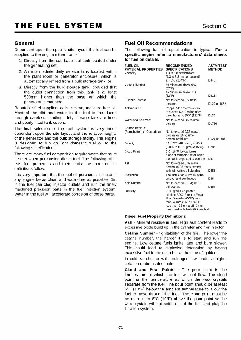
THE FUEL SYSTEM Section C
C1
GeneralDependent upon the specific site layout, the fuel can besupplied to the engine either from:-
1. Directly from the sub-base fuel tank located underthe generating set.
2. An intermediate daily service tank located withinthe plant room or generator enclosure, which isautomatically refilled from a bulk storage tank; or
3. Directly from the bulk storage tank, provided thatthe outlet connection from this tank is at least500mm higher than the base on which thegenerator is mounted.
Reputable fuel suppliers deliver clean, moisture free oil.Most of the dirt and water in the fuel is introducedthrough careless handling, dirty storage tanks or linesand poorly fitted tank covers.
The final selection of the fuel system is very muchdependent upon the site layout and the relative heightsof the generator and the bulk storage facility. The engineis designed to run on light domestic fuel oil to thefollowing specification:-
There are many fuel composition requirements that mustbe met when purchasing diesel fuel. The following tablelists fuel properties and their limits: the more criticaldefinitions follow.
It is very important that the fuel oil purchased for use inany engine be as clean and water-free as possible. Dirtin the fuel can clog injector outlets and ruin the finelymachined precision parts in the fuel injection system.Water in the fuel will accelerate corrosion of these parts.
Fuel Oil RecommendationsThe following fuel oil specification is typical. For aspecific engine refer to manufacturers’ data sheetsfor fuel oil details.
FUEL OIL RECOMMENDED ASTM TEST PHYSICAL PROPERTIES SPECIFICATIONS METHODViscosity 1.3 to 5.8 centistrokes
(1.3 to 5.8mm per second)at 40°C (104°F) D445
Cetane Number 40 Minimum above 0°C(32°F)45 Minimum below 0°C(32°F) D613
Sulphur Content Not to exceed 0.5 mass percent* D129 or 1552
Active Sulfur Copper Strip Corrosion not to exceed No. 2 rating after three hours at 50°C (122°F) D130
Water and Sediment Not to exceed .05 volume percent D1796
Carbon Residue (Ramsbottom or Conradson) Not to exceed 0.35 mass
percent on 10 volume percent residuum D524 or D189
Density 42 to 30° API gravity at 60°F (0.816 to 0.876 g/cc at 15°C). D287
Cloud Point 6°C (10°F) below lowest ambient temperature at which the fuel is expected to operate D97
Ash Not to exceed 0.02 mass percent (0.05 mass percent with lubricating oil blending) D482
Distillation The distillation curve must be smooth and continuous D86
Acid Number Not to exceed 0.1 Mg KOH per 100 ML D664
Lubricity 3100 grams or greaterscuffing BOCLE test or Wear Scar Diameter (WSD) less than .45mm at 60°C (WSD less than .38mm at 25°C) as measured with the HFRR method.
Diesel Fuel Property Definitions
Ash - Mineral residue in fuel. High ash content leads toexcessive oxide build up in the cylinder and / or injector.
Cetane Number - "lgnitability" of the fuel. The lower thecetane number, the harder it is to start and run theengine. Low cetane fuels ignite later and burn slower.This could lead to explosive detonation by havingexcessive fuel in the chamber at the time of ignition.
In cold weather or with prolonged low loads, a highercetane number is desirable.
Cloud and Pour Points - The pour point is thetemperature at which the fuel will not flow. The cloudpoint is the temperature at which the wax crystalsseparate from the fuel. The pour point should be at least6°C (10°F) below the ambient temperature to allow thefuel to move through the lines. The cloud point must beno more than 6°C (10°F) above the pour point so thewax crystals will not settle out of the fuel and plug thefiltration system.

THE FUEL SYSTEM Section C
C2
Distillation - Temperature at which certain portions ofthe fuel will evaporate. The distillation point will vary withthe grade of fuel used.
Sulphur - Amount of sulphur residue in the fuel. Thesulphur combines with the moisture formed duringcombustion to form sulphuric acid.
Viscosity - Influences the size of the atomised dropletsduring injection. Improper viscosity will lead todetonation, power loss and excessive smoke.
Fuels that meet the requirements of ASTM or 2.0 dieselfuels are satisfactory with Cummins fuel systems.
Use of Jet A Fuel in Diesel Engines
Jet A fuel can be used in diesel engines if it has a 40cetane minimum. However, due to the lower specificgravity of the fuel, there will be fewer BTU's available perunit injected, and engine output will be lowered.Specifically all Cummins engines using the PT fuelsystem are Jet A tolerant (most L10, NT, V28 and Krange) and the in-line Bosch pumps as used on the Cand B series engines are Jet A tolerant. However theStanadyne rotary pumps used on the B series are onlymarginally tolerant. Customers should expect to changefuel pumps approx one third the engine rebuild life butwill generally be quite suitable for standby or low hourgensets.
Sub-Base Fuel TankAll Cummins Power Generation sets can be suppliedwith or without base fuel tanks. Capacities vary but aredesigned to provide approximately 8 hours of operationat full load. In practice with a variable load this will beextended. Recommended room layout drawings (SectionB) incorporate base fuel tanks on the generators and theroom height allows for this feature.
This provides a self contained installation without theaddition of external fuel lines, trenches and fuel transferpumps. Generators with base tanks are delivered fullyconnected and ready to run.
All base tanks have provision to accept fuel lines fromexternally mounted bulk fuel tanks or auxiliary freestanding fuel tanks installed in the generator room.
Fuel transfer can be manually, electrically orautomatically transferred via hand operated pumps or
electric motor driven units.
Without Intermediate Fuel Tank (Fig. C1)The simplest arrangement would be to supply the enginedirectly from the bulk storage tank and return the injectorspill directly to this tank. A typical arrangement for this isshown in Fig. C1.
The principle limitations of this method are:
In order to gravity feed the engine, the outlet from thebulk storage tank must be a minimum of 600mmabove the generator plinth level;
The pressure drop of the spill return pipework mustnot exceed that detailed in the Engine Data sheet
The supply pipework from the bulk storage tank to theengine must be sized to allow the total volume of fuelrequired by the engine (consumed fuel plus spill returnfuel) to flow under gravity.
With Intermediate Fuel Tank (Fig. C2)Where, due to site constraints, it is not possible to supplythe engine direct from the bulk tank an intermediate tankcan be located within the plant room/generator enclosurewhich supplies fuel directly to the engine.
This type of system can be further enhanced by theaddition of the following optional items of equipment:
1. An automatic duplex fuel transfer pump andprimary filter system arranged to start the standbypump should the duty pump fail. The transferpump(s) must be sized to cater for the total fuelrequired by the engine, i.e. fuel consumed and thespill return volumes (Fig. C5);
2. A fusible link operated dead weight drop valvedesigned to cut off the supply of fuel to theintermediate tank and to transmit a signal in theevent of fire;
3. A fusible link operated dump valve, arranged todump the contents of the local tank back into thebulk tank in the event of a fire within the generatorenclosure.
The connection details for these additional items ofequipment are indicated. See Fig. C2.

THE FUEL SYSTEM Section C
C3
Fig. C1 Fuel System Without Intermediate Tank
Fig. C2 Fuel System With Intermediate Tank

THE FUEL SYSTEM Section C
C4
Example of a free standing 900 Litre fuel tank installed within a bund wall.
14000 Litre (3000 gallon) bulk fuel tank with a bund wall. Feeding a 500 kVA super silenced set withsufficient fuel for 6 days full load operation.

THE FUEL SYSTEM Section C
C5
Fig. C3 Fuel Tank and Stand Assembly
Daily Service Fuel Tank (Fig. C3)The capacity of a daily Service Tank can be 450 litres,900 or 1300 litres and a transfer system arranged toautomatically feed from the bulk storage tank electricmotor driven pump(s) operating from signals from a levelsensing float switch. Interconnecting pipework should becompatible with the duty of the transfer pump.
Fuel tanks should NOT be made from galvanised iron asdiesel fuel oil reacts against zinc.
The daily service tank should be positioned so that it iseasily accessible for filling. In addition to an automaticfilling system, provision should be made to fill frombarrels by means of a semi-rotary hand pump. The fillconnection should suit the method of filling.
A vent pipe should be extended to the highest pointof the fuel system installation. The diameter of thepipe should at least match that of the fill connection.Provision should be made to prevent the ingress ofdirt.
The overflow from the daily service intermediate tankcan either be:
1. Piped directly back to the bulk storage tank;
2. Piped into the bund of the intermediate tank with abund level alarm system arranged to cut off the fueltransfer pump system on detection of a spillage;
3. Piped to overflow into the bunded area.
The feed connection on the tank should not be lowerthan 600mm above the level on which the engine sits inorder to maintain a gravity feed to the engine. It shouldnot be so high as to exceed the maximum pressure headof the engine’s fuel lift pump. (See Engine Data Sheets).
The spill return connection should not be higher than thesuction lift capability of the engine’s fuel pump. (SeeEngine Data Sheets).
When the intermediate tank is located at a lower levelthan the bulk storage tank it is essential that a solenoidvalve be incorporated into the transfer line.
All final connections to the engine should be in flexiblehose to restrict vibration transmission through the pipe.
Bulk Storage TanksThe purpose of the fuel-supply system is to store anadequate quantity of fuel to suit the application for whichthe system is intended. The bulk storage tanks should besized accordingly.
The filling of the tanks will be by means of a fillconnection housed in a suitable lockable cabinet locatedso as to permit easy access by delivery tanker. Thiscabinet may also house a contents gauge and an overfillalarm connected to the float switch inserted into amanhole on the tank.

THE FUEL SYSTEM Section C
C6
Bulk Storage TanksWhen used with an intermediate tank an electricallydriven fuel transfer pump will be needed. Where possiblethis pump should be located close to the bulk tank on thegrounds that any given size of pump has a greater abilityto push fuel than to pull it. It is good practice to install arelief valve to return excess fuel from the discharge tothe suction side of the pump.
The storage tank should incorporate the followingfacilities:
provision for isolation during cleaning or repair (wheremultiple tanks are installed);
a fill connection;
a vent pipe/breather;
intermediate tank overflow connection;
inspection or manhole cover of approx. 18ins.diameter;
a sludge drain connection at the lowest point;
a level indicator (if contents are transmitted to the fillpoint cabinet); or dipstick
a feed connection at the opposite end to the sludgedrain connection;
strainer and (where necessary) a foot valve.
The tank piers or supports should be arranged so thatthe tank is tilted some 50 from the horizontal. Thesesupports should be constructed or protected so as tohave a standard fire protection of 4 hours and shouldpermit thermal movement. That end of the tank to whichthe principle pipelines are to be connected should besecured to its supports, the other end should be free tomove.
A purpose built bund should be provided for all aboveground tanks, constructed in consideration of thefollowing requirements:
It should be large enough and be structurally soundenough to hold at least 10% more than the contents ofthe tank;
The floor should be laid to fall to an impervious un-drained sump
Walls and floor should be lined with an imperviouslining;
All round access to tank’s sides and fittings should bepossible;
A hand or electric pumping system should facilitatethe draining of the bund.
Metalwork should be earthed in accordance with localregulations.
For underground tanks the size of the excavation shouldbe sufficient to allow for easy installation. The pit shouldbe large enough to permit a clear gap of at least 1mbetween the shell of the tank and the walls beforebackfilling. The tank’s protective coating should not bedamaged when the tank is being lowered onto itssupports and care should be taken that rocks or otherabrasive materials do not damage the tank whenbackfilling. Underground tanks should be fitted with anextended nozzle of sufficient length to bring the manholeclear of the backfill which should be some 0.6m abovethe top of the tank.
Determining Pipe SizesMinimum pipe sizes are determined by the size of theinlet to the fuel transfer pump. The pipe inner diametermust be a least as large as the transfer pump inlet. If thepiping must carry the fuel over long distances, the pipesize must be increased. An auxiliary transfer pump at thetank outlet may also be needed to avoid high suctionpressure within the piping. In all cases, excessive fuelline suction pressures must be avoided. At high suctionpressures the fuel will vaporise in the piping and the fuelsupply to the engine will be decreased.
When selecting pipe for fuel system installation, thecloud points and pour points of the diesel fuel must beconsidered. Over normal temperature ranges, this willnot be a factor. However, as the fuel cloud and pourpoint temperatures are approached, the oil will becomethicker and the pipe size will have to be increased.
When sizing piping, always remember to account forpressure drop across filters, fittings and restrictionvalves.
A flex connector must be added to isolate the enginevibration from the fuel piping. If this vibration is notisolated, the piping could rupture and leak. The flexibleconnector must be as close to the engine transfer pumpsas possible.
Any expanse of exposed piping must be properlysupported to prevent piping ruptures. Use pipe hangersto isolate vibration from the system.
Exposed fuel piping must never run near heating pipes,furnaces, electrical wiring or exhaust manifolds. It thearea around the piping is warm, the fuel lines should beinsulated to prevent the fuel and piping from picking upany excess heat.
All pipes should be inspected for leaks and generalcondition, including cleanliness before installation. Backflush all lines to the tank before start-up to avoid pullingexcess dirt into the engine and fuel piping system. Afterinstallation, the air should be bled from the fuel system.A petcock should included at some high point in thesystem to allow air removal.

THE FUEL SYSTEM Section C
C7
REMOTE FUEL TRANSFER SYSTEM
Bulk fuel tank
SludgeCock
Vent pipe
Fire valvesensing switchBulk
tankgauge
1mTo fuelfillpoint
Shut off
valve
Fire vaultStrainer
Electric pump
Supply & return fuel lines to engine
Bund tosuit bulktank
Bund alarm
Ventpipe
Fig. C4
Fig. C5
GRAVITY FEED FUEL TRANSFER SUPPLY SYSTEM

THE FUEL SYSTEM Section C
C8
Use plugged tees, not elbows, to make piping bends.This will allow for cleaning by removing the plugs andflushing out the lines. All threaded pipe fittings must besealed with a suitable paste.
Caution: Do not use tape to seal fuel line pipe fittings.Pieces of tape could shear off and jam in the pump orinjectors.
Fuel Return Lines
Fuel return lines take the hot excess fuel not used in theengine cycle away from the injectors and back to eitherthe fuel storage tank or the day tank. The heat from theexcess fuel is dissipated in the tank.
Caution: Never run a fuel return line directly back tothe engine fuel supply lines. The fuel will overheat andbreak down.
The fuel return lines should always enter the storageor day tank above the highest fuel level expected.This statement is true for all Cummins Gensets poweredby engines with the PT fuel system (L10, NT, V28 and Krange). However with sets using the B series, C series orthe QST30 series engines drain lines for fuel will causesiphoning back through the supply line and result in hardstarting if installed above the fuel level.
The fuel return line should never be less than one pipesize smaller than the fuel supply line.
Fuel Coolers
Fuel returned to the fuel tank normally collects heat fromthe engine. In some cases, specifically using QSK45 andQSK60 engined gensets, a fuel cooler will be necessaryto be installed within the fuel system.
TYPICAL DIMENSIONS OF BULK FUEL STORAGE TANKS (CYLINDRICAL TYPE)
DIA. LENGTH
500 GALLONS 1372mm 1753mm2273 LITRES 4ft 6ins 5ft 9ins
1000 GALLONS 1372mm 3353mm4546 LITRES 4ft 6ins 11ft 0ins
2000 GALLONS 1981mm 3277mm9092 LITRES 6ft 6ins 10ft 9ins
3000 GALLONS 2134mm 4115mm13638 LITRES 7ft 0ins 13ft 6ins
4000 GALLONS 2438mm 4267mm18184 LITRES 8ft 0ins 14ft 0ins
5000 GALLONS 2286mm 5944mm22730 LITRES 7ft 6ins 19ft 6ins
6000 GALLONS 2744mm 5029mm27276 LITRES 9ft 0ins 16ft 6ins
Fig. C6 Suggested Installation for Bulk and Set Tanks

EXHAUST SYSTEM Section C
C9
Exhaust SystemSizing
An exhaust system should be designed to dispel theexhaust gases to atmosphere at the nearest convenientpoint in an installation. The length of the run and thenumber of changes in direction should be kept to aminimum to avoid exceeding optimum.
The calculation of the effect on the back pressure isbased upon the restriction through the straight lengths ofpipe, the bends and the silencers. The smaller the boreof the pipe, the greater its length and the more times itchanges its direction, the greater is its resistance to flow.The resistance through the silencer varies according tothe level of attenuation it is to achieve.
The formula for this calculation is based upon thefollowing parameters:
F = Exhaust gas flow (Fig. C8)
P = Maximum allowable back pressure
A = Cross sectional area of the pipe
L = Length of straight pipe
B = Number of bends
R = Resistance through the silencer(s)
V = Linear velocity through the silencer
Listed below are pipe nominal bores and their crosssectional areas (A):
Cross Sectional Area of Exhaust Piping
Inches sq. ft2 mm sq. m2
3 0.049 76 0.00454 0.087 102 0.0086 0.196 152 0.0188 0.349 203 0.03210 0.545 254 0.05012 0.785 305 0.07314 1.070 356 0.09916 1.396 406 0.129
Engine Silencer Exhaust Boreinches mm
B3.3, 4B, 6B 3 766C 4 100
L, N, K19, V28 6 152K38, QSK30 6x2 152
K50 8 200QSK45/60 12 300
The back pressure limit for most Cummins engines is 3 ins Hg (76mm Hg) although gensets using the latestdesigns are down to 2 ins Hg (50mm Hg) based on themaximum exhaust flow stated. If in doubt refer to thetechnical data sheets, Section G.
The example given in Fig. C8, shows a typical exhaustrun complete with bends, straight lengths and silencerdetails. The pressure loss in each part of the system isdependent upon the average velocity (V) through it. Addtogether the pressure loss for each part of the system.Take an estimate of the size of the pipe by startingwith the bore of the exhaust flange off the manifoldand increasing the size by 1" for each 20ft length or3 x 90° bends.
Select the silencers required to achieve the noiseattenuation required and determine the linear velocitythrough each one by dividing the flow (F) in ft/sec by thecross sectional area (A) of the bore of the silencer.
eg: L range engines (250 kVA) silencer bore = 6" (152mm) equal to 0.196 sq.ft
Exhaust Gas Flow @ 1500 rpm prime = 1405 cubicft/min.
1405 CFM = 7168 ft/min ÷ 60 = 119 ft/second.0.196 ft2
Bore Velocity. Using 119 against the graph Fig. C10we read off 4 inches Wg (100mm Wg) for silencerresistance.

EXHAUST SYSTEM Section C
C10
Fig. C7 Exhaust pipeline recommendations
Pipe size recommendations*
Exhaust outlet size Up to 6m to 12m 12m to 18m 18m to 24mmm (inches) 6m (20ft) (20 to 40ft) (40 to 60ft) (60 to 80ft)
mm (ins) mm (ins) mm (ins) mm (ins) mm (ins)50 (2) 50 (2) 63 (21⁄2) 76 (3) 76 (3)76 (3) 76 (3) 89 (31⁄2) 100 (4) 100 (4)89 (31⁄2) 89 (31⁄2) 100 (4) 100 (4) 100 (4)
100 (4) 100 (4) 127 (5) 127 (5) 150 (6)127 (5) 127 (5) 150 (6) 150 (6) 200 (8)150 (6) 150 (6) 150 (6) 200 (8) 200 (8)200 (8) 200 (8) 200 (8) 254 (10) 254 (10)254 (10) 254 (10) 254 (10) 305 (12) 305 (12)
* Note. These sizes are for guidance only. Specification and special silencer applications may affect the actual line sizes.
The following formula can be used to calculate the actualback pressure to the exhaust system for a given lengthand diameter.
L x S x Q2
P = —————5184 x D5
L = Pipe length and elbows in feet/metresQ = Exhaust flow CFM/m3/secD = Inside diameter of pipe inches/metresS = Specific weight of exhaust gas lb./cu.ft./kg/m3
S will vary with the absolute temperature of exhaustgas as follows
41 365S = ——————————— S = ———————————
460 + exhaust temp. °F 273 + exhaust temp. °CP = Back pressure (p.s.i.). Must not exceed max.
allowable back pressure as shown in accompanyingtable.
Some useful conversionsMillimeters to inches – multiply by 0.03937Inches to centimetres – multiply by 2.54Metres to feet – multiply by 3.281Cubic metres to cubic feet – multiply by 35.31Centigrade to Fahrenheit – multiply by (C x 1.8) + 32p.s.i. to inches of water (H2O) – divide by 0.0361Inches of water to mm of water – multiply by 25.4Metric formula
L x S x Q2
P = —————77319 x D5
Fig. C8 Typical Exhaust Run
TYPICAL EXHAUST EXTENDED RUNFIRST 9 m (30 ft) of exhaust run – same diameter as engine exhaust outlet.NEXT 6 m of exhaust run – enlarge internal diameter of exhaust by 2.54 cm.THEREAFTER enlarge internal diameter of exhaust 2.54 cm for each 9 m of runup to maximum of 27 m.

EXHAUST SYSTEM Section C
C11
CFM = Cubic feet per minute
*Refer to page G3 for data on B3.3 engines
Bo
re v
elo
city
in m
/sec
Resistance in mm W.g.
150
100
75.0
50.0
40.0
30.0
25.0
20.0
15.0
10.0
500
400
300
200
100
50
40
302.0 3.0 4.0 5.0 10.0 20.0 30.0
7505002501501005025
TYPICAL VELOCITY/RESISTANCE CURVE AT 400°C
Resistance at temperature T°C: RT = R400 x 673
where R400 = resistance at 400°C from graph
T + 273
Bo
re v
elo
city
in f
t/se
c
Resistance in inches W.g.
Fig. C10
Fig. C9 Exhaust Gas Flows and Temperatures
1500 rpm 1800 rpm
Prime Standby Prime Standby
Engine CFM °F CFM °F CFM °F CFM °F4B3.9G* 260 1105 280 1215 325 1120 350 1270
4BT3.9G1 290 870 315 935 370 860 395 9154BT3.9G2 335 970 365 1030 420 950 460 1010
4BTA3.9G1 377 940 352 890 420 950 460 10106BT5.9G2 600 1070 650 1130 745 1010 800 10606CT8.3G2 895 970 980 1040 1100 951 1221 10656CTA8.3G 1090 1180 1205 1210 1380 1095 1515 1130
6CTAA8.3G 1080 1080 1272 1100 1436 925 1605 952LTA10G2 1405 955 1290 935 1655 905 1915 920NT855G6 2270 1065 2450 1125 2290 950 2400 975
NTA855G4 2390 975 2595 1005 1866 895 2030 925NTA855 G6 2270 1065 2450 1125 2290 950 2400 975KTA19G3 2850 975 3155 990 3345 880 3630 915KTA19G4 3039 1000 3398 1604 3673 898 3945 939VTA28G5 4210 920 4340 945 4635 885 5040 935QST30G1 1995 527 2170 538 2620 455 2908 480QST30G2 2216 538 2526 557 2794 467 3118 496QST30G3 2430 541 2720 563 3000 464 3290 481QST30G4 N/A N/A N/A N/A N/A N/A N/A N/AKTA50G3 7900 968 8500 977 8400 860 9100 887KTA50G8 8150 900 9210 950 – – – –KTA50G9 – – – – 9600 880 10650 960QSK60G3 9650 920 10700 940 – – – –QSK60G3 10700 940 11800 960 – – – –QSK60G6 – – – – 12400 760 13400 794QSK60G6 – – – – 13765 805 15150 850

EXHAUST SYSTEM Section C
C12
Pressure drop calculations
Section A - Straight length of pipe.
Section B - 90° bends
Section C - Straight length of pipe, one sixth that ofSection A.
Section D - The exhaust gas silencer, the manufacturersdata is required to calculate the pressuredrop.
Section E - Straight length of pipe, one third that ofSection A
Section F - Outlet, total pressure drop of the exhaustsystem
Fig. C11 Typical Exhaust Run Complete with Bends
Select the appropriate silencer(s) required to achieve thenoise attenuation required and determine the linearvelocity through each one by dividing the flow (F) inft/sec by the cross sectional area of the bore of thesilencer.(A)
e.g. F(8500cfm) = 64.98ft/sec 60 x A(2.180 Ft2)
The resistance through the silencer can be determinedby reference to the silencer manufacturer’s nomograph.(Nelson Burgess BSA range nomograph is shown as Fig.C12). In the event that a reactive and an absorptivesilencer is needed to achieve the noise attenuation level,the absorptive silencer would be placed after the reactiveone and its resistance should be considered the sameas an equivalent bore straight length of pipe.
When added to the resistance through the silencer(s) thetotal should not exceed the maximum allowable backpressure of the engine. If it does, the procedure shouldbe repeated using an increased bore pipe and/orsilencer(s).
11000
2.0
2.0
2.5
3
4
5
6
7
8
9
10
13
1.0
0.5
0.1
0.05
0.020.15
0.01
0.0050.0067 in.Hg
0.0020.00150.001
0.0005
0.00020.00015
0.0001
0.00005
0.00001
10000
9000
8000 Resistance of:
ELBOWS
Use 2X Equivalentof straight pipe
Straight pipe EquivalentLength
90° Elbow = 16 x Dia. in inch/1245° Elbow = 9 x Dia. in inch/12
(cfm
x .4
72 =
l/s)
(in. H
g x
25.
4 =
mm
Hg
)
(inch
es x
25.
4 =
mm
)
Example:2000 cfm = 16 x 6" dia.thru 6in. = 96 in. length equivalentdia elbow = 8ft of 6" pipe
=.0067 x 8 = .0536 in. Hg
FLEX PIPE7000
6000
5000
4500
4000
3500
3000
2500
2000
1500
1000
900
800
600
400
300
250
200
Exhaust Gas Flowcubic feet per minute
Silencer and Exhaust Pipediameter inches
Back Pressure
o cfm ∆P in Hg.per foot
BACK PRESSURE NOMOGRAPH
Fig. C12 Silencer and Straight Line Nomograph

EXHAUST SYSTEM Section C
C13
RoutingOnce the final size and route of the pipework and thesilencer have been established, the exhaust route canbe determined, taking into account the following factors:
A flexible bellows unit must be fitted on the engineconnection to allow the engine to move on itsmountings;
If the silencer is to be located within the plant room,due to its physical size and weight it may need to besupported from the floor;
It may be necessary to install expansion joints at eachchange of direction to compensate for the thermalgrowth in the pipe during operation;
The inner radius of a 90° bend should be 3 times thediameter of the pipe;
The primary silencer should be mounted as close aspossible to the engine;
When installing a long exhaust system, it may benecessary to install a terminal silencer to reduce anyregenerated noise that may occur in the pipework afterthe primary silencer.
The termination point should not be directed atcombustible materials/structures, into hazardousatmospheres containing flammable vapours, where thereis a danger that the gases will re-enter the plant roomthrough the inlet air vent, or into any opening to otherbuildings in the locality.
All rigid pipework should be installed in such a mannerthat the engine’s exhaust outlet is not stressed. Pipesshould be routed so that they are supported by fixturesto the building fabric or by existing structural steelworkwhere such methods are acceptable;
InstallationDue to its overall size and weight, if the silencer is to belocated within the plant room consideration should begiven during the initial planning stages of the installationas to the exact method of moving this item into the roomand then lifting it into final position as it may benecessary for it to be installed before the generator set ismoved into position.
To ensure that condensation does not run back into theexhaust manifold, horizontal pipes should slopedownwards away from the engine. Provision should bemade for extending the condensate drain on the silencerand any other drain points, such as those at the base ofvertical pipework, to a readily accessible position forregular draining to take place.
Where the pipe passes through combustible roofs, wallsor partitions it should be protected by the use of metalsleeves with closing plates infilled with mineral wool.(See Fig. C13).
Fig. C13 Protection by the Use of Metal Sleeves
Where possible, in order to reduce the heat gain into theplant room, as much of the exhaust system as possibleshould be located outside of the plant room, with theremaining pipework within the room being fully laggedand clad. However, if due to the specific site constraintsit is necessary to install the silencer and additionalpipework within the room it should be fully insulated with50mm of mineral wool and clad with aluminium foil. Itmay also be necessary to install the silencer inside theplant room to avoid noise break-out from the pipeconnecting to the engine side of the silencer.
Care should be taken when insulating at pipe support orguide points so that the thermal growth of the pipe cantake place. (See Fig. C14).
Fig. C14 Allowing for Thermal Growth
At the termination point the pipe should be protectedagainst the ingress of rain either by turning into thehorizontal plane with a mitred end or by being fitted witha rain cap.

EXHAUST SYSTEM Section C
C14
Exhaust System Design Considerationsand Requirements
Noise LevelThe exhaust noise created by the engine must beattenuated sufficiently to satisfy all local regulations andon-site requirements. This can be accomplished withproper silencer selection.
– Industrial (or Non-Critical) 12 to 18 dBA attenuation– Residential 18 to 25 dBA attenuation– Critical 25 to 35 dBA attenuation
System RestrictionIt is important to keep the exhaust back pressure as lowas possible. Excessive exhaust back pressure cancontribute to poor engine performance and poordurability by negatively affecting combustion efficiencyand increasing gas temperatures.
The back pressure limit on many Cumminsgenerator drive engines is normally 3 in Hg (76mmHg) but can be down to 2 in Hg (50mm Hg) on thelatest engines based on the maximum exhaust gasflow stated on the Engine Data Sheet. To satisfy thisrequirement, it is important to minimize piping length,elbow quantities, and silencer restriction, and tomaximize piping diameters.
Exhaust Outlet LocationLocation Planning
Normally, the discussion for the exhaust outlet locationwould be included within a discussion of piping design.However, the exhaust outlet location is worthy of adedicated discussion.
The most convenient exhaust outlet location is notalways the best location. The designer must recognizethat prevailing winds, building design, property layout,the distance to the property line, and the availableexhaust gas velocity are each critical ingredients inselecting the proper outlet location. The gases must nothave the opportunity to enter any vital air inlets(windows, doors, ventilation ducts, engine combustionair intakes, engine cooling/ventilation intakes, etc.), andmany items must be considered to prevent this.
Every precaution must be taken when selecting theproper exhaust outlet location to prevent exhaust gasesfrom contaminating the air entering vital air inlets. Suchvita air inlets include windows, building ventilationsystems, engine combustion air intakes, doors, andengine cooling/ventilation intakes.
Special consideration must be given to prevailingwinds, and potential stagnant air pockets near
buildings. These are as important as the mere distancebetween the exhaust outlet and the vital air inlets.
The exhaust outlet must be located so as tominimize the effects of stack noise on workers andneighbours and to minimize the potential of carbonparticle accumulation on nearby structures and tominimize the effects of noise.
Piping DesignAll exhaust piping must be well supported by the buildingor enclosure.
The silencer must never be mounted directly to theexhaust manifold or turbocharger outlet on any enginewithout supplementary support.
The exhaust outlet must be fitted with a rain cap, bonnet,or otherwise be designed to prevent rainwater and snowfrom entering the exhaust system.
A condensate trap and drain valve must be fitted asclose as practical to the engine to collect any watervapour that might condense from the exhaust gas.
System CostsExhaust systems certainly cost money, but shaving costson the front end of a project may well cost the end-user agreat deal over the life of the unit. A restrictive systemwill force the engine to run at an unacceptable air to fuelratio and could lead to temperature related durabilityproblems and smoke complaints.
System LengthThe designer must make every effort to find the shortestpractical exhaust piping route between the engine andthe properly selected exhaust outlet location. Thefollowing list summarises some of the reasons why thesystem should be as short as possible:
– Minimize system restriction (back pressure).
– Maintain reasonable exhaust gas exit velocities sothat gases are easily dispersed (largest possibleplume).
– Minimize exhaust gas condensing so that gasesare not excessively dense when they exit.
Dense gases exiting at a low velocity contribute tosmoke complaints and to poor dispersion.
Flexible Connections
The piping system will expand and contract as it heatsand cools. It will also be susceptible to the vibration andmotion of the engine. For these reasons, a flexible pipingconnection must be placed between the engine and thepiping system. The flexible pipe will minimize thestresses on the engine and the stresses in the piping

EXHAUST SYSTEM Section C
C15
Good example of clean and well lagged exhaust installation run from two 725 kVA twelve cylinder engined poweredstandby sets.
Dual exhaust run, lagged andaluminium foil clad from a CumminsVTA28 twelve cylinder twinturbocharged engine. Set output 640 kVA/50 Hz.
EXHAUST SYSTEM Section C
C16
system. The flexible pipe should be located at or nearthe engine exhaust outlet (turbo or exhaust manifold).
Mandatory Accessories
The exhaust outlet must be fitted with a rain cap, bonnetor otherwise be designed to prevent rainwater and snowfrom entering the exhaust system. Flapper-type raincaps are effective devices, but they are subject to theeffects of corrosion and carbon buildup which canprevent them from operating properly. It is wise to usethese only in applications where they can be easilyaccessed for maintenance.
A condensate trap and drain valve must also be fitted asclose as practical to the engine to collect any watervapour that might condense from the exhaust gas. Such
a device is recommended, but rarely practical for aportable unit.
Common Systems for Multiple Exhaust Sources
The practice of manifolding or plumbing engines into acommon exhaust system with furnaces, boilers, or otherengines is not recommended. Non-running engines areat great risk to suffer damage due to the buildup ofcarbon and condensation from a running engine or otherexhaust source. The turbocharger on a non-runningengine can be driven by the exhaust flow from othersources and result in turbocharger bearing damage dueto lack of lubrication.
There is no effective way to safely isolate engines from acommon piping system. Valves used in the piping toisolate specific branches tend to suffer from carbonbuildup and eventually leak or become stuck.
The exhaust gas velocities also tend to suffer in asystem like this especially when only a few exhaustsources are operating. The exhaust gases condense anddo not disperse well at the outlet. It may be possible todevelop a forced air system to push the gases throughthe common stack to achieve the desired velocity, butthis adds complication to the system. Cummins has noexperience with such a forced air/blower system.

EXHAUST SYSTEM Section C
C17
Standard Exhaust Bellows
Standard Exhaust Flex

EXHAUST SYSTEM Section C
C18
GA of Exhaust Silencers (Industrial)
GA of Exhaust Silencers (Residential)

EXHAUST SYSTEM Section C
C19
DC controlwiring
90° elbow/sweeping elbow
Condensationdrain trap
Silencer
Flexible section
Wall platesand sleeve
Air outlet duct
AC powerwiring
Concretebase
Air in
IMPORTANT!Cooling air inlet must be at least 1-1/2 times
larger than radiator duct outlet area on radiator cooled models
Flow or cooling air and heated air can be controlled by automatically
operated louvres
Typical Installation

THE COOLING SYSTEM Section C
C20
GeneralCooling and ventilation of an engine room is veryimportant. Provision must be made for an adequate airflow through the room, to replace the air consumed bythe engine, and air pushed out by the cooling radiatorfan.
There are various types of cooling systems that can beadopted, the main ones being as follows.
Set mounted radiator.
Remotely positioned radiator.
Heat exchanger cooling.
IMPORTANTRadiator Cooled Sets
When a radiator is mounted on the end of theplant main frame, position the set so that theradiator is as close to the outlet vent as possible,otherwise recirculation of hot air can take place.The recommended maximum distance away fromthe outlet vent is 150mm without air ducting.
If the plant cannot be positioned as above an air ductmust be incorporated in the system.
The minimum cross sectional area of the ducting mustbe the same as the cooling area of the radiator. A canvasduct with mating steel flanges to suit radiator and outputlouvres is normally adequate for this purpose.
Ducting bends must be well radiused and where longruns are required the ducting must be enlarged to reduceback pressure on the radiator. Sound attenuated ductsrequire long runs and have to be designed specificallyfor each building.
The air inlet and outlet apertures in a building arenormally louvred or screened with mesh. The free areataken up by the louvring slats or mesh must be takeninto consideration when calculating size of aperture.
The large volume of air required by a diesel engine forcooling and combustion is not always appreciated and itis recommended that the total area of incoming air ventsshould be at least double that of the engine radiatoroutlet. All vents should be protected against the ingressof rain. In cold climates where sets are employed onstandby duty and only run occasionally, the room shouldbe kept warm. Air inlets and radiator outlets should beprovided with adjustable louvres that can be closedwhen the set is not in use. Thermostatically controlledimmersion heaters are generally fitted in the enginecoolant system on automatic mains failure sets, asstandard.
DampersDampers or louvres protect the genset and equipmentroom from the outside environment. Their operation ofopening and closing should be controlled by operation ofthe genset.
In cooler climates movable or discharge dampers areused. These dampers allow the air to be recirculatedback to the equipment room. This enables the equipmentroom to be heated while the genset engine is still cold,increasing the engine efficiency.
Radiator Set RequirementsRadiator set cooling air is drawn past the rear of the setby a pusher fan that blows air through the radiator.Locate the air inlet to the rear of the set. Make the inletvent opening 1-1/2 to 2 times larger than the radiatorarea.
Locate the cooling air outlet directly in front of theradiator and as close as possible. The outlet openingmust be at least as large as the radiator area. Lengthand shape of the air outlet duct should offer minimumrestriction to airflow.
The radiator has an air discharge duct adapter flange.Attach a canvas or sheet metal duct to the flange andthe air outlet opening using screws and nuts so duct canbe removed for maintenance purposes. The ductprevents circulation of heated air. Before installing theduct, remove the radiator core guard.
Standard Radiator Cooling uses a set mountedradiator and engine pusher fan to cool engine waterjacket. Air travels from the generator end of the set,across the engine and out through the radiator. Anintegral discharge duct adapter flange surrounds theradiator grille.
Remote Radiator Cooling (Optional) substitutes aremote mounted radiator and an electrically driven fanfor the set mounted components. Removal of theradiator and the fan from the set reduces noise levelswithout forcing dependence on a continuous coolingwater supply. The remote radiator installation must becompletely protected against freezing.
Before filling cooling system, check all hardware forsecurity. This includes hose clamps, capscrews,fittings and connections. Use flexible coolant lineswith heat exchanger, standpipe or remote mountedradiator.

THE COOLING SYSTEM Section C
C21
VentilationVentilation of the generator room is necessary to removethe heat and fumes dissipated by the engine, generatorand its accessories and to provide combustion air.
Factory-mounted Radiator Ventilation
In this configuration the fan draws air over the set andpushes it through the radiator which has flanges forconnecting a duct to the out-of-doors. Consider thefollowing:
See the Generator Set Data Sheet for the designairflow through the radiator and allowable airflowrestriction. The allowable air flow restrictionmust not be exceeded. The static pressure (airflow restriction) should be measured to confirm,before the set is placed in service, that the systemis not too restrictive, especially when ventilating airis supplied and discharged through long ducts,restrictive grilles, screens and louvers.
Note that the inlet duct must handle combustion airflow (see the Set Data sheet) as well as ventilatingair flow and must be sized accordingly.
Louvres and screens over air inlet and outletopenings restrict air flow and vary widely inperformance. A louvre assembly with narrowvanes, for example, tends to be more restrictivethan one with wide vanes. The effective open areaspecified by the louvre or screen manufacturershould be used.
The airflow through the radiator is usually sufficientfor generator room ventilation. See the examplecalculation for a method of determining the air flowrequired to meet room air temperature risespecifications, if any.
Because the radiator fan will cause a slightnegative pressure in the generator room, it is highlyrecommended that combustion equipment such asthe building heating boilers not be located in thesame room as the generator set. If this isunavoidable, it will be necessary to determinewhether there will be detrimental effects, such asbackdraft, and to provide means (extra large roominlet openings and/or ducts, pressurising fans, etc.)to reduce the negative pressure to acceptablelevels.
Engine driven fan
Inlet airdamper
Coolair
Hotair
Measure static pressurewithin 6 inches (150mm)
of the radiator.
Flexible ductconnector
Outlet airdamper
Not less thanheight of radiator
Radiator
Prevailing winds
Wind/noisebarrier
Thermostatically controlled louvre (to order)
Fig. C15 Factory-Mounted Radiator Cooling

THE COOLING SYSTEM Section C
C22
In colder climates, automatic dampers should beused to close off the inlet and outlet air openings tokeep the generator room warm when the set is notrunning. And, a thermostatic damper should beused to recirculate a portion of the radiatordischarge air to reduce the volume of cold air thatis pulled through the room when the set is running.The inlet and outlet dampers must fully open whenthe set starts. The recirculating damper shouldclose fully at 16°C (60°F) .
Other than recirculating radiator discharge air intothe generator room in colder climates, allventilating air must be discharged directly to theout-of-doors. It must not be used to heat any spaceother than the generator room.
A flexible duct connector must be provided at theradiator to take up generator set movement andvibration and prevent transmission of noise.
Ventilating air inlet and discharge openings shouldbe located or shielded to minimize fan noise andthe effects of wind on airflow.
Example Ventilating Air Flow Calculation: Thegenerator set Specification Sheet indicates that the heatradiated to the room from the generator set (engine andgenerator) is 4,100 BTU/min (72 kW). The silencer and10 feet of 5-inch diameter exhaust pipe are also locatedinside the generator room. Determine the air flowrequired to limit the air temperature rise to 30°F.
1. Add the heat inputs to the room from all sources.Table 11 indicates that the heat loss from 5-inchexhaust pipe is 132 BTU per min per foot of pipe and2,500 BTU per min from the silencer. Add the heatinputs to the room as follows:
2. The required air flow is proportional to the total heatinput divided by the allowable room air temperaturerise:
58 x Total Heat 58 x 7,920Required Air Flow = —————————— = ————— = 15,312 cfm
Temp Rise (∆°F) 30
Engine room ventilation can be estimated by thefollowing formulas:
HV (cfm) = —————————— + Engine Combustion Air
0.070 x 0.24 x ∆ T
or
HV (m3/min) = —————————— + Engine Combustion Air
1.099 x 0.017 x ∆ T
V = Ventilating air (cfm) (m3/min).
H = Heat radiation (Btu/min) (kW).
∆T = Permissible temperature rise in engine room (°F) (°C).
Density of air at 100°F = 0.070 lb/cu ft (1.099 kg/m3).
Specific heat of air = 0.24 Btu/°F (0.017 kW/°C).
Assuming 38°C (100°F) ambient air temperature.
Heat from Generator Set ................................................4,100Heat from Exhaust Pipe 10 x 132...................................1,320Heat from Silencer ..........................................................2,500
———TOTAL HEAT TO GENERATOR ROOM (Btu/Min) .......7,920
(Btu)——Min
HEAT FROM PIPE HEAT FROM SILENCERSPIPE DIAMETER BTU/MIN-FOOT BTU/MIN
INCHES (mm) (kJ/Min-Metre) (kJ/Min)1.5 (38) 47 (162) 297 (313)2 (51) 57 (197) 490 (525)
2.5 (64) 70 (242) 785 (828)3 (76) 84 (291) 1,100 (1,160)
3.5 (98) 96 (332) 1,408 (1,485)4 (102) 108 (374) 1,767 (1,864)5 (127) 132 (457) 2,500 (2,638)6 (152) 156 (540) 3,550 (3,745)8 (203) 200 (692) 5,467 (5,768)10 (254) 249 (862) 8,500 (8,968)12 (305) 293 (1,014) 10,083 (10,638)
Fig. C16 Heat Losses from Uninsulated ExhaustPipes and Silencers
Guide to Heat radiated to room from Engine and Alternator
kW/minEngine @50Hz @60HzB3.3G1 15.4 13.1B3.3G2 15.4 21.14B3.9G 10.8 11.4
4BT3.9G1 13.1 154BT3.9G2 15 17
4BTA3.9G1 15.5 186BT5.9G2 22 256CT8.3G2 34 366CTA8.3G 35 40
6CTAA8.3G 36 N/ALTA10G2 41 50
LTA10G3/G1 46 55NT855G6 57 N/A
NTA855G4/G2 65 72NTA855G6/G3 81 76
KTA19G2 N/A 85KTA19G3 79 95KTA19G4 88 99VTA28G5 114 133QST30G1 126 153QST30G2 137 166QST30G3 137 152QST30G4 152 N/AKTA38G4 N/A 197KTA50G3 176 229KTA50G8 236 N/AKTA50G9 N/A 224
1 kW/min = 56.8 Btu/min Fig. C17QSK60 – Refer to Tech Data Sheets

THE COOLING SYSTEM Section C
C23
aaaaaaaaaaaaaaaaaaaaaaaaaaaaaaaaaaaaaaaaaaaaaaaaaaEXHAUST HUNG FROM CEILING
50mm MINERAL LAGGINGAND ALUMINIUM CLAD
FLEXIBLE EXHAUSTBELLOWS
WEATHER LOUVRESEE NOTES
WALL PLATES & SLEEVESEE NOTES
EXHAUST
GX
H
K
C
H
TRENCH TOSWITCHROOM
J B
M
N
E
L
FUEL TRANSFERTRENCH IF BULKTANK INCLUDED
SEE NOTESRE PLANT ACCESS
F
1000
D
A
SET
SUB BASE FUEL TANK
AIRFLOW
AIRFLOW
TRENCH
SEE NOTES
CABLE TRENCH
CANVASDUCTING
PANEL PC005(IF SUPPLIED)
600
Cummins Generating Sets 37 KVa - 511 KVa – exhaust run and radiator coolingGenerator room layout without Acoustic Treatment (see page B6 for table dimensions)

THE COOLING SYSTEM Section C
C24
Remote Radiator Cooled SystemsWhere space in a below ground level installationprecludes the use of ducting a number of alternativemethods of cooling are available.
Conventional small cooling tower which is reasonablycheap, simple to install and maintain, or a separateradiator system which can be constructed as shown infigure 18. The radiator in this system is separated fromthe engine and the fan driven by an electric motor.
The radiator with an electric driven fan can be suppliedas a totally enclosed unit for outside use, or an opentype for installation inside a building
When the radiator is mounted more than 3.0 metreshigher than the set, on most engines a break tank andan electric driven water pump is required. The size of thebreak tank depends on the capacity of the entire coolingsystem.
Water is circulated from the break tank through theradiator and engine by means of an electrically drivencirculating pump.
As the radiator electric fan motor and water circulatingpump are powered by the generator, this loadrequirement must be added to the total set power.
As the water from the radiator will drain into the breaktank when the set is at rest, the tank must have sufficientcapacity to f ill the entire cooling system when the set isrunning, and still retain enough coolant for it to circulateefficiently.
Precautions Required with this System
The following precautions are required:
1. Against contamination of coolant water by foreignmatter.
2. Water becoming oxygenated through turbulence inbreak tank.
3. Avoidance of air locks in system (pipes shouldhave vent points).
4. Suitable water treatment to engine manufacturers’recommendations.
5. Protect against freezing.
6. Engine runs virtually unpressurised.
If the radiator is mounted at the same level as the engineand no break tank is required, an expansion tank shouldbe fitted just above the radiator to allow for theexpansion of the coolant water.
Ventilating air inlet
Engine mountedheat exchnager
Flexiblewater connections
Raw waterdischarge
Raw watersupply
Ventilating fan
Hot air
Prevailing winds
FACTORY-MOUNTED HEAT EXCHANGER COOLING AND VENTILATION FLOW
Air in
Expansion/deaerationtank
Fig. C17
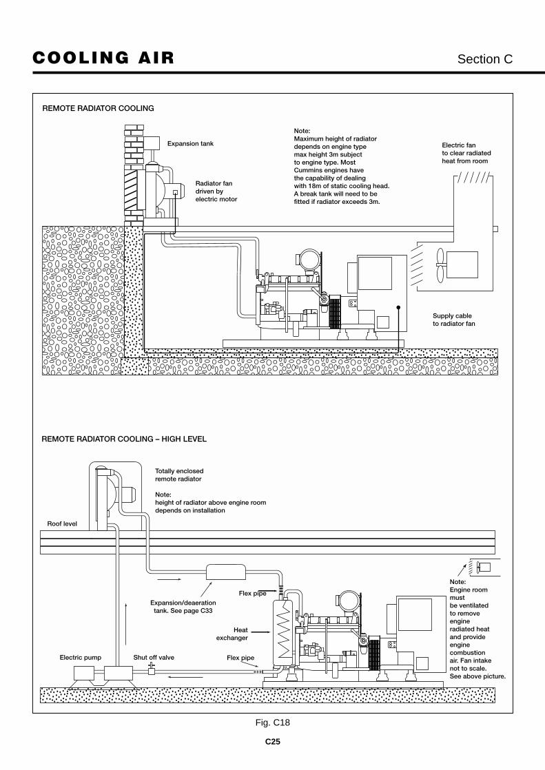
COOLING AIR Section C
C25
@@@@@@@@@@@@@@@@@@@@@@@@@@@@@@@@@@@@@@@@@@@@@@@@@@@@@@@@@@@@
ÀÀÀÀÀÀÀÀÀÀÀÀÀÀÀÀÀÀÀÀÀÀÀÀÀÀÀÀÀÀÀÀÀÀÀÀÀÀÀÀÀÀÀÀÀÀÀÀÀÀÀÀÀÀÀÀÀÀÀÀ
@@@@@@@@@@@@@@@@@@@@@@@@@@@@@@@@@@@@@@@@@@@@@@@@@@@@@@@@@@@@
ÀÀÀÀÀÀÀÀÀÀÀÀÀÀÀÀÀÀÀÀÀÀÀÀÀÀÀÀÀÀÀÀÀÀÀÀÀÀÀÀÀÀÀÀÀÀÀÀÀÀÀÀÀÀÀÀÀÀÀÀ
@@@@@@@@@@@@@@@@@@@@@@@@@@@@@@@@@@@@@@@@@@@@@@@@@@@@@@@@@@@@
ÀÀÀÀÀÀÀÀÀÀÀÀÀÀÀÀÀÀÀÀÀÀÀÀÀÀÀÀÀÀÀÀÀÀÀÀÀÀÀÀÀÀÀÀÀÀÀÀÀÀÀÀÀÀÀÀÀÀÀÀ
@@@@@@@@@@@@@@@@@@@@@@@@@@@@@@@@@@@@@@@@@@@@@@@@@@@@@@@@@@@@
ÀÀÀÀÀÀÀÀÀÀÀÀÀÀÀÀÀÀÀÀÀÀÀÀÀÀÀÀÀÀÀÀÀÀÀÀÀÀÀÀÀÀÀÀÀÀÀÀÀÀÀÀÀÀÀÀÀÀÀÀ
@@@@@@@@@@@@@@@@@@@@@@@@@@@@@@@@@@@@@@@@@@@@@@@@@@@@@@@@@@@@
ÀÀÀÀÀÀÀÀÀÀÀÀÀÀÀÀÀÀÀÀÀÀÀÀÀÀÀÀÀÀÀÀÀÀÀÀÀÀÀÀÀÀÀÀÀÀÀÀÀÀÀÀÀÀÀÀÀÀÀÀ
@@@@@@@@@@@@@@@@@@@@@@@@@@@@@@@@@@@@@@@@@@@@@@@@@@@@@@@@@@@@
ÀÀÀÀÀÀÀÀÀÀÀÀÀÀÀÀÀÀÀÀÀÀÀÀÀÀÀÀÀÀÀÀÀÀÀÀÀÀÀÀÀÀÀÀÀÀÀÀÀÀÀÀÀÀÀÀÀÀÀÀ
@@@@@@@@@@@@@@@@@@@@@@@@@@@@@@@@@@@@@@@@@@@@@@@@@@@@@@@@@@@@
ÀÀÀÀÀÀÀÀÀÀÀÀÀÀÀÀÀÀÀÀÀÀÀÀÀÀÀÀÀÀÀÀÀÀÀÀÀÀÀÀÀÀÀÀÀÀÀÀÀÀÀÀÀÀÀÀÀÀÀÀ
@@@@@@@@@@@@@@@@@@@@@@@@@@@@@@@@@@@@@@@@@@@@@@@@@@@@@@@@@@@@
ÀÀÀÀÀÀÀÀÀÀÀÀÀÀÀÀÀÀÀÀÀÀÀÀÀÀÀÀÀÀÀÀÀÀÀÀÀÀÀÀÀÀÀÀÀÀÀÀÀÀÀÀÀÀÀÀÀÀÀÀ
@@@@@@@@@@@@@@@@@@@@@@@@@@@@@@@@@@@@@@@@@@@@@@@@@@@@@@@@@@@@
ÀÀÀÀÀÀÀÀÀÀÀÀÀÀÀÀÀÀÀÀÀÀÀÀÀÀÀÀÀÀÀÀÀÀÀÀÀÀÀÀÀÀÀÀÀÀÀÀÀÀÀÀÀÀÀÀÀÀÀÀ
@@@@@@@@@@@@@@@@@@@@@@@@@@@@@@@@@@@@@@@@@@@@@@@@@@@@@@@@@@@@
ÀÀÀÀÀÀÀÀÀÀÀÀÀÀÀÀÀÀÀÀÀÀÀÀÀÀÀÀÀÀÀÀÀÀÀÀÀÀÀÀÀÀÀÀÀÀÀÀÀÀÀÀÀÀÀÀÀÀÀÀ
@@@@@@@@@@@@@@@@@@@@@@@@@@@@@@@@@@@@@@@@@@@@@@@@@@@@@@@@@@@@
ÀÀÀÀÀÀÀÀÀÀÀÀÀÀÀÀÀÀÀÀÀÀÀÀÀÀÀÀÀÀÀÀÀÀÀÀÀÀÀÀÀÀÀÀÀÀÀÀÀÀÀÀÀÀÀÀÀÀÀÀ
@@@@@@@@@@@@@@@@@@@@@@@@@@@@@@@@@@@@@@@@@@@@@@@@@@@@@@@@@@@@
ÀÀÀÀÀÀÀÀÀÀÀÀÀÀÀÀÀÀÀÀÀÀÀÀÀÀÀÀÀÀÀÀÀÀÀÀÀÀÀÀÀÀÀÀÀÀÀÀÀÀÀÀÀÀÀÀÀÀÀÀ
@@@@@@@@@@@@@@@@@@@@@@@@@@@@@@@@@@@@@@@@@@@@@@@@@@@@@@@@@@@@
ÀÀÀÀÀÀÀÀÀÀÀÀÀÀÀÀÀÀÀÀÀÀÀÀÀÀÀÀÀÀÀÀÀÀÀÀÀÀÀÀÀÀÀÀÀÀÀÀÀÀÀÀÀÀÀÀÀÀÀÀ
@@@@@@@@@@@@@@@@@@@@@@@@@@@@@@@@@@@@@@@@@@@@@@@@@@@@@@@@@@@@
ÀÀÀÀÀÀÀÀÀÀÀÀÀÀÀÀÀÀÀÀÀÀÀÀÀÀÀÀÀÀÀÀÀÀÀÀÀÀÀÀÀÀÀÀÀÀÀÀÀÀÀÀÀÀÀÀÀÀÀÀ
@@@@@@@@@@@@@@@@@@@@@@@@@@@@@@@@@@@@@@@@@@@@@@@@@@@@@@@@@@@@
ÀÀÀÀÀÀÀÀÀÀÀÀÀÀÀÀÀÀÀÀÀÀÀÀÀÀÀÀÀÀÀÀÀÀÀÀÀÀÀÀÀÀÀÀÀÀÀÀÀÀÀÀÀÀÀÀÀÀÀÀ
@@@@@@@@@@@@@@@@@@@@@@@@@@@@@@@@@@@@@@@@@@@@@@@@@@@@@@@@@@@@
ÀÀÀÀÀÀÀÀÀÀÀÀÀÀÀÀÀÀÀÀÀÀÀÀÀÀÀÀÀÀÀÀÀÀÀÀÀÀÀÀÀÀÀÀÀÀÀÀÀÀÀÀÀÀÀÀÀÀÀÀ
@@@@@@@@@@@@@@@@@@@@@@@@@@@@@@@@@@@@@@@@@@@@@@@@@@@@@@@@@@@@
ÀÀÀÀÀÀÀÀÀÀÀÀÀÀÀÀÀÀÀÀÀÀÀÀÀÀÀÀÀÀÀÀÀÀÀÀÀÀÀÀÀÀÀÀÀÀÀÀÀÀÀÀÀÀÀÀÀÀÀÀ
@@@@@@@@@@@@@@@@@@@@@@@@@@@@@@@@@@@@@@@@@@@@@@@@@@@@@@@@@@@@
ÀÀÀÀÀÀÀÀÀÀÀÀÀÀÀÀÀÀÀÀÀÀÀÀÀÀÀÀÀÀÀÀÀÀÀÀÀÀÀÀÀÀÀÀÀÀÀÀÀÀÀÀÀÀÀÀÀÀÀÀ
@@@@@@@@@@@@@@@@@@@@@@@@@@@@@@@@@@@@@@@@@@@@@@@@@@@@@@@@@@@@
ÀÀÀÀÀÀÀÀÀÀÀÀÀÀÀÀÀÀÀÀÀÀÀÀÀÀÀÀÀÀÀÀÀÀÀÀÀÀÀÀÀÀÀÀÀÀÀÀÀÀÀÀÀÀÀÀÀÀÀÀ
@@@@@@@@@@@@@@@@@@@@@@@@@@@@@@@@@@@@@@@@@@@@@@@@@@@@@@@@@@@@
ÀÀÀÀÀÀÀÀÀÀÀÀÀÀÀÀÀÀÀÀÀÀÀÀÀÀÀÀÀÀÀÀÀÀÀÀÀÀÀÀÀÀÀÀÀÀÀÀÀÀÀÀÀÀÀÀÀÀÀÀ
@@@@@@@@@@@@@@@@@@@@@@@@@@@@@@@@@@@@@@@@@@@@@@@@@@@@@@@@@@@@
ÀÀÀÀÀÀÀÀÀÀÀÀÀÀÀÀÀÀÀÀÀÀÀÀÀÀÀÀÀÀÀÀÀÀÀÀÀÀÀÀÀÀÀÀÀÀÀÀÀÀÀÀÀÀÀÀÀÀÀÀ
@@@@@@@@@@@@@@@@@@@@@@@@@@@@@@@@@@@@@@@@@@@@@@@@@@@@@@@@@@@@
ÀÀÀÀÀÀÀÀÀÀÀÀÀÀÀÀÀÀÀÀÀÀÀÀÀÀÀÀÀÀÀÀÀÀÀÀÀÀÀÀÀÀÀÀÀÀÀÀÀÀÀÀÀÀÀÀÀÀÀÀ
@@@@@@@@@@@@@@@@@@@@@@@@@@@@@@@@@@@@@@@@@@@@@@@@@@@@@@@@@@@@
ÀÀÀÀÀÀÀÀÀÀÀÀÀÀÀÀÀÀÀÀÀÀÀÀÀÀÀÀÀÀÀÀÀÀÀÀÀÀÀÀÀÀÀÀÀÀÀÀÀÀÀÀÀÀÀÀÀÀÀÀ
@@@@@@@@@@@@@@@@@@@@@@@@@@@@@@@@@@@@@@@@@@@@@@@@@@@@@@@@@@@@
ÀÀÀÀÀÀÀÀÀÀÀÀÀÀÀÀÀÀÀÀÀÀÀÀÀÀÀÀÀÀÀÀÀÀÀÀÀÀÀÀÀÀÀÀÀÀÀÀÀÀÀÀÀÀÀÀÀÀÀÀ
@@@@@@@@@@@@@@@@@@@@@@@@@@@@@@@@@@@@@@@@@@@@@@@@@@@@@@@@@@@@
ÀÀÀÀÀÀÀÀÀÀÀÀÀÀÀÀÀÀÀÀÀÀÀÀÀÀÀÀÀÀÀÀÀÀÀÀÀÀÀÀÀÀÀÀÀÀÀÀÀÀÀÀÀÀÀÀÀÀÀÀ
@@@@@@@@@@@@@@@@@@@@@@@@@@@@@@@@@@@@@@@@@@@@@@@@@@@@@@@@@@@@
ÀÀÀÀÀÀÀÀÀÀÀÀÀÀÀÀÀÀÀÀÀÀÀÀÀÀÀÀÀÀÀÀÀÀÀÀÀÀÀÀÀÀÀÀÀÀÀÀÀÀÀÀÀÀÀÀÀÀÀÀ
@@@@@@@@@@@@@@@@@@@@@@@@@@@@@@@@@@@@@@@@@@@@@@@@@@@@@@@@@@@@
ÀÀÀÀÀÀÀÀÀÀÀÀÀÀÀÀÀÀÀÀÀÀÀÀÀÀÀÀÀÀÀÀÀÀÀÀÀÀÀÀÀÀÀÀÀÀÀÀÀÀÀÀÀÀÀÀÀÀÀÀ
Expansion tank
Roof level
Electric pump Shut off valve Flex pipe
Flex pipe
Note:Engine room must be ventilatedto remove engine radiated heatand provide engine combustion air. Fan intake not to scale. See above picture.
Heatexchanger
Totally enclosedremote radiator
Note: height of radiator above engine roomdepends on installation
Radiator fandriven byelectric motor
Supply cableto radiator fan
Note:Maximum height of radiatordepends on engine typemax height 3m subject to engine type. Most Cummins engines have the capability of dealing with 18m of static cooling head. A break tank will need to be fitted if radiator exceeds 3m.
Electric fanto clear radiatedheat from room
REMOTE RADIATOR COOLING
REMOTE RADIATOR COOLING – HIGH LEVEL
@@ÀÀ@@ÀÀ@@ÀÀ@@ÀÀ@@ÀÀ@@ÀÀ@@ÀÀ@@ÀÀ@@ÀÀ@@ÀÀ@@ÀÀ@@ÀÀ@@ÀÀ@@ÀÀ@@ÀÀ@@ÀÀ@@ÀÀ@@ÀÀ@@ÀÀ@@ÀÀ@@ÀÀ@@ÀÀ@@ÀÀ@@ÀÀ@@ÀÀ@@ÀÀ@@ÀÀ
Expansion/deaerationtank. See page C33
Fig. C18

THE COOLING SYSTEM Section C
C26
Four heat exchange cooled KTA50 Powered 1256 kVA sets run continuously for a factory in Spain.
Where sets are in basement areas flexible trunking direct to the air intake cleaner ensures a cool supply.

THE COOLING SYSTEM Section C
C27
Heat Exchanger
In situations where a constant source of cold water isavailable, such as a reservoir or river, a heat exchangercan be fitted to cool the engine. However, where directwater cooling is used the quality of the water has animportant bearing on the life of the engine. Natural water,such as that from rivers, lakes, reservoirs and ponds cancarry scale forming impurities so the raw water should bepassed through the tubes of the heat exchanger. Theraw water is passed through the tubes rather than theengine coolant because the tubes can be cleaned moreeasily than the outside. It is necessary to establish thecomposition and quality of the water to ensure correctselection of materials for the tubes.
The heat exchanger should be located within the plantroom adjacent to the engine, with a header tank locatedlocally above the height of the engine or heat exchanger. The circulating pump should be located at alow point within the system, as generally the pumps havea greater pushing capacity compared with their liftingability).
Fig. C19 Heat Exchanger
The heat exchanger pipework recommended should besteel, cast iron or neoprene, or in some casesaluminium, copper or galvanised steel. All connections tothe engine should be by means of flexible pipes to avoidthe transmission of vibration.
When locating the heat exchanger within the plant roomarea an allowance should be made for the radiated heatfrom the units when selecting the ventilation fans.
Cooling Tower
Where, due to site limitations such as high ambient airtemperature, it is not practical to cool the engine bymeans of a standard package, a cooling tower is used inconjunction with a heat exchanger. Under thesecircumstances the cooling tower, heat exchanger andcirculating pump would need to be selected to form amatched system. The pump should provide the requiredflow rate whilst overcoming the resistance’s of the heatexchanger, the cooling tower and interconnectingpipework.
The raw water, after passing through the engine heatexchanger, is pumped to the cooling tower where theheated water is cooled by running over slats into areservoir. The cooled water is then returned to theengine heat exchanger. To aid the cooling, a motoroperated fan, may be required depending on the size ofthe tower and amount of water to be cooled. Foroptimum efficiency, the water circulating pump for thecooling tower, should also be mounted within the plantroom adjacent to the heat exchanger. The cooling towershould be located in a convenient position outside theplant room.
Fig. C20 Cooling Tower

THE COOLING SYSTEM Section C
C28
Example of 600 kW Heat Exchanger Cooling Standby Set.
Four set (1 MW) Heat Exchange Cooling Installation for Base Load Operation.

THE COOLING SYSTEM Section C
C29
Typical Friction Losses in Water Pipe (Old pipe)(Flow v Nominal Pipe Diameter)
Flow Nominal Pipe Diameterg/min L/sec 0.75" 1.0" 1.25" 1.5" 2.0" 2.5" 3.0"
(19.05mm) (25.4mm) (31.75mm) (38.1mm) (50.8mm) (63.5mm) (76.2mm)Head Loss in ft/100 ft
(m / 100 ft)5 .34 10.5 3.25 0.84 0.40 0.16 0.0510 .63 38.0 11.7 3.05 1.43 0.50 0.17 0.0715 .95 80.0 25.0 6.50 3.05 1.07 0.37 0.1520 1.26 136.0 42.0 11.1 5.20 1.82 0.61 0.2525 1.58 4.0" 64.0 16.6 7.85 2.73 0.92 0.38
(101.6mm)30 1.9 0.13 89.0 23.0 11.0 3.84 1.29 0.5435 2.21 0.17 119.0 31.2 14.7 5.10 1.72 0.7140 2.52 0.22 152.0 40.0 18.8 6.60 2.20 0.9145 2.84 0.28 5" 50.0 23.2 8.20 2.76 1.16
(127mm)50 3.15 0.34 0.11 60.0 28.4 9.90 3.32 1.3860 3.79 0.47 0.16 85.0 39.6 13.9 4.65 1.9270 4.42 0.63 0.21 113.0 53.0 18.4 6.20 2.5775 4.73 0.72 0.24 129.0 60.0 20.9 7.05 2.9380 5.05 0.81 0.27 145.0 68.0 23.7 7.90 3.2890 5.68 1.00 0.34 6.0" 84.0 29.4 9.80 4.08
(152.4mm)100 6.31 1.22 0.41 0.17 102.0 35.8 12.0 4.96125 7.89 1.85 0.63 0.26 7.0" 54.0 17.6 7.55
(177.8mm)150 9.46 2.60 0.87 0.36 0.17 76.0 25.7 10.5175 11.05 3.44 1.16 0.48 0.22 8.0" 34.0 14.1
(203.2mm)200 12.62 4.40 1.48 0.61 0.28 0.15 43.1 17.8225 14.20 5.45 1.85 0.77 0.35 0.19 54.3 22.3250 15.77 6.70 2.25 0.94 0.43 0.24 65.5 27.1275 17.35 7.95 2.70 1.10 0.51 0.27 9.0" 32.3
(228.6mm)300 18.93 9.30 3.14 1.30 0.60 0.32 0.18 38.0325 20.5 10.8 3.65 1.51 0.68 0.37 0.21 44.1350 22.08 12.4 4.19 1.70 0.77 0.43 0.24 50.5375 23.66 14.2 4.80 1.95 0.89 0.48 0.28 10.0"
(254.0mm)400 25.24 16.0 5.40 2.20 1.01 0.55 0.31 0.19425 26.81 17.9 6.10 2.47 1.14 0.61 0.35 0.21450 28.39 19.8 6.70 2.74 1.26 0.68 0.38 0.23475 29.97 - 7.40 2.82 1.46 0.75 0.42 0.26500 31.55 - 8.10 2.90 1.54 0.82 0.46 0.28750 47.32 - - 7.09 3.23 1.76 0.98 0.591000 63.09 - - 12.0 5.59 2.97 1.67 1.231250 78.86 - - - 8.39 4.48 2.55 1.511500 94.64 - - - 11.7 6.24 3.52 2.131750 110.41 - - - - 7.45 4.70 2.802000 126.18 - - - - 10.71 6.02 3.59
Fig. C21 Typical Friction Losses in Water Pipe

THE COOLING SYSTEM Section C
C30
Line VelocitiesWater velocity guidelines are as follows:
12
0
2
3.5
3
2.5
2
1.5
1
.5
4 6 8 10 12 14 16 18 20 22 24 26 28 l/s
50 100 150 200 250 300 350 400 450 GPM
FPSM/S
10
8
6
4
2
38.1 mm1.50
50.82.00
63.52.50
76.23.00
893.50
1024.00
1144.50
127 mm5.00
Flow
Velo
city
VELOCITY vs FLOWStd. pipe sizes 1 1/2in. to 5in. (38.1 to 127 mm)
1250 kVA base power generators with heat transfer system.
Fig. C23

WATER TREATMENT Section C
C31
GeneralThe engine cooling system is subject to rust andcavitation attacks. To minimise the severity of thiscondition an anti-corrosive agent can be added to totallyclean and limpid coolant water.
An antifreeze solution is also required to prevent freezingof the coolant in the cold weather.
Engine Coolant Water for coolant should be clean and free from anycorrosive chemicals such as chlorides, sulphates andacids. It should be kept slightly alkaline with a pH valuein the range 8.5 to 10.5.
Generally, any water which is suitable for drinking can beused, with treatment as described below.
Protection against corrosion
Supplemental Coolant Additive (Cummins DCA4 orequivalent) is required to protect the cooling system fromfouling, solder blooming and general corrosion.
The use of antifreeze is also recommended as DCA4concentrations are dependent upon the presence ofantifreeze. Antifreeze also interacts with DCA4 to providegreater corrosion and cavitation protection.
Procedure for Treating Coolant
1. Add the required amount of water to a mixingcontainer and dissolve in the required quantity ofDCA.
Caution: Allow the cooling system to cool down beforeremoving the radiator cap. Observe themanufacturer's instructions regarding pressurisedcooling systems and take great care when removingthe pressure cap.
2. Add the required amount of antifreeze, if used, tothe water solution and mix thoroughly.
3. Add the coolant to the cooling system and replacethe radiator cap securely.
Cold Weather Protection
Antifreeze must be added to the coolant where there isany possibility of freezing to protect the engine fromdamage due to coolant freezing I unfreezing.
A 50% antifreeze / 50% water mixture is recommendedbecause DCA4 concentrations are dependent upon thepresence of antifreeze. The dosage of DCA4 must beincreased to higher concentration if antifreeze is notadded to the coolant. A low-silicate antifreeze isrecommended.
Engine WarmingWhere thermostatically controlled immersion heatersoperating from the mains supply are fitted in the coolingsystem these maintain the temperature of the coolant incold weather.
A heater alone, fitted in the radiator will not be adequatefor starting or preventing freezing, so an antifreezemixture should be used.

COMBUSTION AIR Section C
C32
The engine charge combustion and aspirated air systemcomponents are as follows:
Air Intake filter (all engines)
Turbocharger (most engines)
Exhaust Gas Bellows (all engines)
Exhaust Gas Silencer(s) (all engines)
The main function of the charge air / exhaust gas systemis to provide the engine with fresh combustion air ofsufficient quality and quantity, and to provide the meansof silencing and venting the combustion gases. (See this Section for the Exhaust System). To prevent re-circulation, hot air must be ducted out of the plant roomor enclosure directly through a flexible duct and an airoutlet louvre. An insufficient air supply will cause carbondeposits on the engine components.
Air Intake FilterDry Type Air Intake Filter
A dry type air intake filter unit is normally fitted to theengine to prevent the ingress of dirt or dust into thecombustion systems.
The intake filter can be supplied loose for mounting onan outside wall of the enclosure or plant room, piped andvented to the air intake system on the engine.
Air Combustion Flows
Refer to Section G Technical Data for engine aircombustion flow figures.
Heavy Duty Air Intake Filters
In severe locations such as the desert, heavy duty airintake cleaners are required. They consist of one ormore pleated paper elements, which are fire resistantand waterproof. The dust and dirt particles in the air aredeposited on the paper fibres, gradually building up to arestrictive limit in which the element must be cleaned orreplaced.
In other installations with extreme conditions (cementfactories, etc.) the highest allowed particleconcentrations at turbocharger inlets are as follows:
Cement dust 10mg/m3
Calcium hydroxide 5mg/m3
Chlorine 1.5mg/m3
Oxides of sulphur 20mg/m3

COOLING AIR Section C
C33
Heat Rejection (Radiated Heat)Whilst the cooling water system detailed in Section 7serves to remove a substantial amount of the heatproduced by the engine, an additional amount is rejectedinto the room from the following sources:-
The alternator, in terms of direct radiation from themachine body and from its integral fan cooling system
Radiated heat from the engine assembly.
The sections of the exhaust system within the room,especially unlagged sections of pipework or thesilencer.
Details of the level of heat rejected to the ambient by theengine and alternator are given on the specification datasheets or in the project technical specification. Heatrejected from the exhaust pipework and manifolds istaken into consideration for the assessment of the totalamount of heat that will be dissipated into the plantroom. Typically, 10% of the value given in the enginedata sheets as "heat rejected to exhaust" will cover theexhaust system provided it is lagged.
The ventilation system should be designed to limit thetemperature rise within the plant room between 10to15°C (18 to 27°F) above the ambient when operatingat full load. If the resultant temperature within the plantroom exceeds 40°C the aspiration air should be ducteddirect from the atmosphere to the engine.
Cooling Air Flow CalculationUtilising the total heat rejection value, the cooling air flowrequired through the plant room can be calculated usingthe following formula:-
Rejected Heat (KW) X 58Air Flow (cfm) = —————————————————
Air Density (0.07) x Specific heat of air (0.238) x Temp Rise (F°)
Where:
The total kW of heat rejected is sourced from allequipment within the plant room: the engine; thealternator; the exhaust pipework and silencers etc.
The temperature rise is the maximum rise aboveambient permissible within the plant room (can varybetween 10 to 15°C (18 to 27°F).
Ventilation Fans and LouvresWhere cooling radiators are mounted externallyventilation fans are used to remove this volume of airfrom the plant room. The air inlet and discharge louvresmust be sized for this amount plus the aspiration airrequirement (if this is being drawn from within the plantroom).
Where the cooling radiator is mounted within the plantroom, an aperture should be positioned in an externalwall directly in line with the air flow through the radiator.The radiator has a discharge duct adapter in which acanvas flexible duct may be attached, this directsunwanted hot air out of the plant room and prevents re-circulation of the hot air. Re-circulation can also bepossible if the inlet and discharge air apertures are tooclose together.
In some applications it is required to remove the heatlosses from the plant room while the generator is atstandstill. Inlet and outlet louvres may be motorised toautomatically move into the open position when thegenerator is started, or where the air blast radiator is ofthe pressure type, the outlet louvres may be gravityoperated.
Expansion/Deaeration TanksFigs 17 and 18 illustrate provision for an expansion/deaeration tank above the heat exchanger. In generalthere are included with the heat exchanger, alternativelyyou may need to arrange the fabrication of this tank.
Components of Expansion/Deaeration Top Tanks
Cooling system must be designed so that when a coldsystem is completely filled there is at least a 6% (max8%) additional capacity to allow for coolant expansionwhen it is at operating temperature with the correctcoolant concentration. This extra volume is obtained byproper location of the FILL NECK. The distance betweenthe underside of the roof of the tank and the bottom ofthe fill neck is the area in the tank used for expansion ofthe fluid when it is heated, i.e. at least 6% of the totalsystem volume.
Radiator Cap
Fill Neck
Core Vent TubeTop Tank
Deaeration Area
Fill Line ConnectionBaffleCoolant Inlet
Connection
Engine VentLine Connection
Expansion Area
Vent Hole Located at theVery Top of Fill Neck
Core Vent Tube1/2" to 1/4" from Top of Tank
Tank Large Enough toProvide Minimum Drawdown
Radiator Cap
Neck Extension with VentHole (To Provide Expansion
Space)
Top of TubesSolid BaffleSealed All Around
Well
Connection forFill Line
Coolant Inlet(Below Baffle)
DeaerationArea
Connection for Vent Line(Above Coolant Level)

STARTING SYSTEMS Section C
C34
Electric Starting SystemsElectric starting systems are generally used on allgensets.
Electric starting systems employ a starter motor, flangemounted on the flywheel housing and driving theflywheel through a pinion and "Bendix" type geararrangement. For larger engines, a twin starterarrangement may be used.
The power source for electric starting systems is a 12 or24VDC battery system. The starting voltage isdetermined by engine size, 24VDC being used for largerengines to reduce starting current and hence cable size.Control of starting is via a start solenoid which iscontrolled by the genset control system.
Starter Arrangement
On start up, the "Bendix" gear maintains engagement ofthe starter motor pinion with the flywheel until the enginereaches self sustaining speed. At that stage a speedsensing device automatically de-energises the startsolenoid which removes the supply to the electric starterand starter motor pinion disengages from the flywheel.
Battery Systems
Types of Batteries Used
Batteries are of two types - lead acid and NiCad. Leadacid batteries are generally used, being the leastexpensive. NiCad batteries are used where longer life,etc., is required.
Installing a Battery System
Batteries are an essential part of any standby generatorsystem and some 90% of all generator failures are dueto batteries. It is therefore vital that batteries are stored,commissioned and maintained to the required standards.
On most Cummins Power Generation sets provisionsmade for lead acid batteries to be fitted on the generatorchassis. A battery rack is provided for this purpose. IfNiCad batteries are provided the following advice shouldbe followed.
When installing a battery system for an electric startersystem consideration should be given to the following:
Space requirement - for larger gensets the batterysystem may require a considerable floor area.
Install the battery system in a clean, well lit, andwell ventilated area. If installed in a cubicle,adequate ventilation must be provided. Easyaccess should be provided for maintenance - forchecking electrolyte level, topping up cells, etc.
If the battery must be placed on the floor it isnecessary to use battens, preferably on insulators.This will raise crates or cell bottoms clear of anydamp or dust which may accumulate.
Avoid installing batteries in a hot area. For optimumefficiency it is preferable to operate NiCad batterieswithin the range 15°C to 25°C. It is essential thatfiller openings of all cells are readily accessible.
Place crates or tapered blocks of cells in thecorrect position for connecting-up as a battery. Fitinter-crate, or inter-block connectors and then themain battery leads. Tighten all nuts firmly with abox spanner. Smear the battery terminals withpetroleum jelly to prevent corrosion.
Battery charging system - This may be a charge alternator which charges
the batteries only when the set is running, and /or
Mains powered battery charger which willmaintain the battery system in a chargedcondition when the set is not running and ispowered from a mains supply.
Note: a mains powered battery charger must befed with power from a "maintained supply", notfrom the set output.
During the charging of a battery, explosive gasesare given off.
Caution: Ensure that batteries are charged in a wellventilated area, away from naked flames and sparks.
Caution: When putting a battery into service on agenset, connect the earth lead LAST; when removingthe battery, disconnect the earth lead FIRST.
Caution: Ensure correct polarity when connecting thebattery to the genset. Even momentary incorrectconnection may cause damage to the electricalsystem. Connect the positive generator cable FIRST,followed by the negative ground.
Starting Aids
It is customary to maintain coolant temperatures above40°C min. to promote quick starting on an emergencygenerating plant. Thermostatically controlled immersionheaters, deriving their supply from the primary source ofpower, are fitted in the engine cooling system to providethis heating. For severe circumstances it is advisable toinclude a similar heater for lubricating oil temperatures.
Avoid installing lead acid batteries in the same room asNiCad batteries as these will deteriorate due to gaseousfumes from the lead acid batteries.

ELECTRICAL SYSTEM Section C
C35
Verify all electrical connections are secure andall wiring is complete and inspected. Replaceand secure any access panels that may havebeen removed during installation.
Battery Connections! WARNING Accidental starting of the generator
set can cause severe personal injury or death. Makesure that the Run/Off/Auto switch on the controlpanel is set to the Off position before connecting thebattery cables.
Sets with LTA10 engines and above require 24 voltbattery current, using two or four, 12 volt batteries (seeSpecification section). Connect the batteries in series(negative post of first battery to the positive post of thesecond battery) as shown below.
Necessary battery cables and rack are on the unit.Service batteries as necessary. Infrequent use (as inemergency standby service), may allow battery to self-discharge to the point where it cannot start the unit. Ifinstalling an automatic transfer switch that has no built-incharge circuit, connect a separate trickle charger.Cummins automatic transfer switches include such abattery charging circuit.
! WARNING Ignition of explosive battery gasescan cause severe personal injury. Always connectbattery negative last to prevent arcing.
! WARNING Be sure battery area has been wellventilated prior to servicing near it. Lead-acidbatteries emit a highly explosive hydrogen gas thatcan be ignited by arcing, sparking, smoking, etc.Ignition of these gases can cause severe personalinjury.
175 Through 1500 kW Genset Battery Connections

NOISE CONTROL Section C
C36
Legislation to control environmental noise pollution insensitive areas exists and must be complied with, butgenerally it will be the local authority who will determinethe requirements. Planning must be sought with the localauthority to determine the noise level of the equipment.The requirements for noise control will depend on theenvironmental conditions and operating time at theproposed location of the generating set and associatedequipment.
There are two types of noise to be considered:-
Structure borne noise - emanates from the vibrationscreated by the generating set and associatedconnected equipment. Minimise this type of noise byuse of anti vibration mounts and flexible connections.
Airborne Noise - emanated from the generating set inparticular at the high end of the frequency range.
Noise Reduction MethodsReduction of structure borne noise can be achieved byuse of anti vibration mountings and flexible hangers andconnections. Reductions of airborne noise can beachieved by the use of splitter attenuators, exhaust gasmufflers, acoustic wall and ceiling linings, acoustic inletand outlet louvres, enclosures and drop over canopies.
In addition the use of slow speed fans within a plantroom or an internally mounted heat exchanger with anexternally mounted, low noise cooling tower would beadvantageous whilst locating them outside the plantroom in acoustic housings.
Enclosures can be supplied for installing over agenerating set within a plant room to isolate the rest ofthe building from noise.
The noise level at a given location is a resultant from allsources, once the level is known and the site restrictionsare known, the sound attenuation louvre sizes andequipment can be considered and selected as required.
Each engine has a noise spectrum for both mechanicalnoise coming off the block and for the exhaust noiseemitting from the end of the pipe. This information,together with the combustion and cooling air flowrequirements and maximum pressure restrictionsallowable should be provided to the noise attenuationequipment suppliers to size the splitter attenuatorsrequired for the inlet and discharge air apertures andsilencers for the exhaust gas.
See Section F Silenced Generators.
Noise LegislationNoise Legislation relating to generators working onconstruction and building sites exists throughout allcountries in the EEC or are directives of the EEC.
Noise Legislation in other Countries France 85dB(A) at 1m for a generating set
on any construction site within 50metres of a residential area.
W. Germany 80dB(A) at 1m for a generating seton any construction site within 50metres of a residential area.
Sweden Swedish standard SEN590111 setsa limit of 85dB(A). This is applied forthe purpose of reducing theexposure of employed personswhere the level of sound iscontinuous for eight hours in anyone day. Hearing protection must beused when the level exceeds85dB(A). The equivalent is 90dB(A)in the UK at present.
U.S.A The OSHA Safety and Healthstandard sets the limit of 90dBA foran eight hour exposure, 95dB(A) forfour hours and 100dB(A) for twohours.

PLANT ROOM PROVISIONS Section C
C37
Auxiliary AC SuppliesAuxiliary AC supplies must be provided for all auxiliaryequipment (e.g., ventilation fans, heaters, pumps, etc.),together with the associated AC distribution panel. Amotor control unit (MCC) may be provided whereapplicable.
Fire ProtectionDiesel fuel can be stored safely above ground in suitablecontainers. Whilst the flash point is high, it isinflammable and suitable fire fighting equipment shouldbe provided.
Provision for fire fighting equipment should be made inthe initial design of the plant room. The storage areashould be adjacent to an access door, if possible.
Foam or CO2 should be used for oil fires, i.e. fuel oil, gas,lubricating oils etc.
CO2 or CTC should be used for electrical fires or nearbare conductors.
Sand can be used for minor and isolated fires.
Under NO circumstances should water be used tocontrol a fire in the plant room.
ToolsA standard kit of engine tools are supplied with the plant.They should be protected from corrosion and stored in asafe dry place.
SparesIf spares are supplied with the plant they should beprotected against corrosion and stored in a safe dryplace.
Plant Room Lighting & StagingThe plant room should be well illuminated to assistmanual operations and maintenance. Natural lightingfrom windows should give good illumination to criticalareas. Double glazing on windows will reduce heat lossand emitted noise.
To provide access to elevated items on larger plants itmay be necessary to erect suitable staging which mustprovide safe access.
Maintenance SpaceAll component parts of the installation should haveample space and access around them to assistmaintenance.
The control cubicle should have sufficient free space toenable all access doors and panels to be opened andremoved.
Space should be left around the plant to give safe andeasy access for personnel.
There should be a minimum distance of 1 metre fromany wall, tank or panel within the room.


CONTROL SYSTEM Section D
D1
Generator Control PanelThe generator set is controlled locally by a dedicatedGenerator Control Panel. This incorporates the controlsystems, metering and alarm indications and customerconnections.
Two forms of control system are currently available; PCLand PowerCommandTM control, described below.
PCL (Power Control)PCL is a low cost generator set monitoring, metering andcontrol system which provides local control of thegenerator set and forms part of the main control panel.This control system provides high reliability and optimumgenerator set performance.
Two versions of PCL are available:
PCL 001 which provides generator set control withmanual start.
PCL 002 which provides generator set control withremote start.
Both units provide generator start / stop and indicateoperational status. In the event of a fault, the units willindicate the fault condition(s) and in the case ofshutdown faults, e.g., low oil pressure, automatically shutdown the engine. Faults are indicated by means ofLED’s.
PCL 002 may be used with an Automatic Transfer Switch(ATS) Control Unit which senses mains failure, suppliesa remote start signal to the generator set control unit andprovides breaker control.
An alarm annunciator module, with 6 input channels and6 corresponding LED’s configurable to customerrequirements, may be used as a protection expansionunit, an annunciator or a combination of both. Each unitprovides two relay outputs. A maximum of two alarmannunciator units modules can be fitted to the generatorcontrol panel.
PowerCommandTM Control (PCC)PowerCommandTM Control (PCC) is a microprocessor-based generator set monitoring, metering and controlsystem which provides local control of the generator set.This system provides high reliability and optimumgenerator set performance.
PCC provides an extensive array of integrated standardcontrol and display features, eliminating the need fordiscrete component devices such as voltage regulator,governor and protective relays. It offers a wide range ofstandard control and digital features so that customcontrol configurations are not needed to meet applicationspecifications. Refer to the Cummins Technical Manual.
Two versions of PowerCommandTM are available:
PowerCommandTM Generator Set Control whichprovides generator set control for single sets.
PowerCommandTM Generator Set Control ParallelingVersion which provides generator set control withparalleling for multi set applications.
Major Control features include: Digital governing, voltage regulation, synchronising
and load sharing control. Electronic overcurrent alternator protection. Analogue and digital AC output metering. Digital alarm and status message display. Generator set monitoring status display of all
critical engine and alternator functions. Starting control including integrated fuel ramping to
limit black smoke and frequency overshoot withoptimised cold weather starting.
Easy servicing. Communications network capability.
The Power Command Control meets or exceeds therequirements of the following codes and standards:
UL508 - Category NIWT7 for US an Canadian Usage.
ISO 8528-4 - Control Systems for reciprocating engine- driven generator sets. Canadian Standards - 282-M1
14 CSAC22.2, No - M91 for industrial ControlEquipment.
NFPA 70 - US National Electrical Code
NFPA 110 - Emergency Power Systems. Meets allrequirements for Level 1 systems.
AS3000 SAA Wiring Rules
AS3009 Emergency Power Supplies
AS3010.1 Electrical Supply by Generator Sets.
Mil Std 461 Electromagnetic Emission andSusceptibility Requirements.
IEC801.2 Electrostatic Discharge Test
IEC801.3 Radiated Susceptibility
IEC801.4 Electrically Fast Transient
IEC801.5 / IEEE587 Surge Immunity

CONTROL SYSTEM Section D
D2
AC power toemergency loads
DC start signalfrom ATS,
change over contactorsor customer signal
DC signalsto remote
annunciator
Set runningsignals
Remoteemergency
stop
Normal AC powerto control box heater
Normal AC powerto generator
heater
Normal AC powerto coolant
heater
DC signalsto generator
control and remote annunciator
DC power to battery charger
Normal AC power tobattery charger
AC power today tank
fuel pump
DC signalsto remote
annunciator
AC power to remotevent or radiator fan
Day tankfuel pump
Battery charger1
TYPICAL GENERATOR SET CONTROL AND ACCESSORY WIRING
Notes:1. The items in italics are not always used
Fig. D1

Typical Automatic Mains Fail ApplicationPCL or PCC configuration
A single generating set with control system PCL002 or PCC, an automatic transfer switch and a transferswitch controller (the PCL005)
Wall mounting PCL005 mains failure controlsystem, providing two wire start output whenthe mains fails. This incorporates mains fail,mains return and run on timers.
PCL002 or PCC control system withtwo wire start input from the mainsfailure control unit PCL005
Automatic Transfer Switch (ATS)wall mounting up to 1250 A anda free standing from 1600 A to3200 A.
MAINS
LOAD ATS
BREAKERNon-automatic
PERCENT LOAD HERZ AC VOLTS PERCENT AMPERES
Warning
Upper scale
L1- L2 L1-L2 L1L2- L3 L1- L2 L2
L3- L1
Voltage
Phase selectSelf Test Panel Lamps
3ph 1ph
Amps
Shutdown
Paralleling Breaker
Closed
Open
OffRun Auto Push foremergency stop
L1
V Hz
L2 L3
WTGöV OPG
PCL005
PCC
PCL002
D3

CONTROL SYSTEM Section D
D4
Parallel OperationPowerCommandTM Digital Paralleling Systems areavailable for isolated prime power, emergency standbyor interruptible applications utility (mains) parallelingapplications. These systems are unique in that they usefully integrated, microprocessor-based control for allsystem control functions to eliminates the need forseparate paralleling control devices such assynchronisers and load sharing controls.
PowerCommandTM Control allows state of the artservicing of the entire paralleling control systemintegration, monitoring and adjustment of systemparameters with a laptop computer.
The PowerCommandTM Control incorporates AmpSentryProtection for paralleling operations. This is acomprehensive power monitoring and control systemintegral to the PowerCommandTM Control that guards theelectrical integrity of the alternator and power systemfrom the effects of overcurrent, short circuit, over/undervoltage, under frequency, overload, reverse power, lossof excitation, alternator phase rotation and parallelingcircuit breaker failure to close. Current is regulated to300% for both single phase and 3 phase faults when ashort circuit condition is sensed.
If the generating set is operating for an extended periodat a potentially damaging current level, an overcurrentalarm will sound to warn the operator of an impending
problem before it causes a system failure. If anovercurrent condition persists for the time pre-programmed in the time/current characteristic for thealternator, the PMG excitation system is de-energised,avoiding alternator damage. The overcurrent protectionis time delayed in accordance with the alternator thermalcapacity. This allows current to flow until secondaryfuses or circuit breakers operate, isolate the fault andthus achieve selective co-ordination.
Fixed over/under voltage and under frequency timedelayed set points also provide a degree of protection forload equipment. Over/under voltage conditions trigger ashutdown message on the digital display screen andunder frequency conditions prompt both warning andshutdown message, depending on the length of time andmagnitude of variance below rated frequency.
AmpSentry protection includes an overload signal thatcan be used in conjunction with transfer switches ormaster controls to automatically shed load, preventing apotential generating set shutdown. The overload signal isprogrammable for operation at a specific kW level, onthe basis of an under frequency condition, or both. It alsoincludes protection for generating set reverse power,loss of excitation, alternator phase rotation andcircuit breaker failure to close. It includes permissive(synchronising check functions for automatic and manualbreaker closure operations.
Seven 900 kVA sets working in parallel for a major soft drinks bottling factory in the Middle East.

CONTROL SYSTEM Section D
D5
Twelve 1250 kVA sets working together as construction camp base power using the PCL control system.
Thirty-nine 1125 kVA sets with KTA50 engines produce a combined 30MW of site power usingPowerCommand Control (PCC) and Digital Master Control Systems when all operating in parallel.

Typical Paralleling ApplicationPCC configuration
An unlimited number of sets can be paralleled together with PCC(P). Each set must have a PCCP and be nomore than 20 metres away from the next set. PCCP requires a motorised breaker. Motorised breakers mustbe mounted in a free standing cubicle.
PCCP on each set linked bymulticore cable
Motorised generator breakers(free standing)
LOAD
Non-automatic
PERCENT LOAD HERZ AC VOLTS PERCENT AMPERES
Warning
Upper scale
L1- L2 L1-L2 L1L2- L3 L1- L2 L2
L3- L1
Voltage
Phase selectSelf Test Panel Lamps
3ph 1ph
Amps
Shutdown
Paralleling Breaker
Closed
Open
OffRun Auto Push foremergency stop
Non-automatic
PERCENT LOAD HERZ AC VOLTS PERCENT AMPERES
Warning
Upper scale
L1- L2 L1-L2 L1L2- L3 L1- L2 L2
L3- L1
Voltage
Phase selectSelf Test Panel Lamps
3ph 1ph
Amps
Shutdown
Paralleling Breaker
Closed
Open
OffRun Auto Push foremergency stop
PCCP
PCCP
BREAKER 1SET 1
SET 2
BREAKER 2
D6

MC 150 Control Typical ApplicationTwo set standby application – automatic synchronising
Features: Master first startPriority load add & load shedLoad demandAMF
Once signalled to start (by manual input or remote start signal) the MC150will: start both sets, sense which reaches rated speed and volts first andswitch this set onto the load, the remaining sets are then synchronised tothis first set to start. Each set (maximum total of 4) is controlled to take itsproportional share of the load.
Motorised generator breakers(free standing)
LOAD
Non-automatic
PERCENT LOAD HERZ AC VOLTS PERCENT AMPERES
Warning
Upper scale
L1- L2 L1-L2 L1L2- L3 L1- L2 L2
L3- L1
Voltage
Phase selectSelf Test Panel Lamps
3ph 1ph
Amps
Shutdown
Paralleling Breaker
Closed
Open
OffRun Auto Push foremergency stop
PCCP
Non-automatic
PERCENT LOAD HERZ AC VOLTS PERCENT AMPERES
Warning
Upper scale
L1- L2 L1-L2 L1L2- L3 L1- L2 L2
L3- L1
Voltage
Phase selectSelf Test Panel Lamps
3ph 1ph
Amps
Shutdown
Paralleling Breaker
Closed
Open
OffRun Auto Push foremergency stop
PCCP
MAINS
MC150
PCL005
ATS
BREAKER 2
BREAKER 2
SET 1
SET 2
D7

MC 150 PLTE Control Typical ApplicationSingle set standby / peak lop application
Features: Mains monitoringEssential & non-essential loadcontrolPeak lop auto or manualG59 utility protectionMax time in parallel warningAMF (integral no PCL005)Load shareN-E contactor controlOn & off load testNo break returnVolt free signals
The MC150 PLTE is a configurable controller designed tooperate as an automatic mains failure system with theoption of full output or peak-lopping in three modes: –automatic, manual or share.
Motorised generatorbreakers (free standing)
NON-ESSENTIALLOAD
ESSENTIALLOAD
Non-automatic
PERCENT LOAD HERZ AC VOLTS PERCENT AMPERES
Warning
Upper scale
L1- L2 L1-L2 L1L2- L3 L1- L2 L2
L3- L1
Voltage
Phase selectSelf Test Panel Lamps
3ph 1ph
Amps
Shutdown
Paralleling Breaker
Closed
Open
OffRun Auto Push foremergency stop
PCCP
MAINS
MC150 PLTE & G59
BREAKER 1
ATS
D8

CONTROL SYSTEM Section D
D9
NetworkingThe PowerCommandTM Control includes a GeneratorControl Module (GCM) which allows for communicationsover the PowerCommandTM Network. The Network is suitable for local or remote control and monitoringusing PowerCommandTM Network hardware andPowerCommandTM software for Windows“. See Fig. 28.
The Network provides complete and consistent control,monitoring and information access, additionally, all alarmevents may be programmed to automatically dial out to auser specified telephone number upon alarmoccurrence. This provides all the required information,when needed, from unattended sites. All eventsincluding alarms, operator activities and system eventsare recorded and may be printed as reports or saved todisk for archiving purposes.
PowerCommandTM software for windows allows thefacility for remote monitoring of the generation sites. ARemote Access, Single Site version of Power Commandwill be provided for a host monitoring computer. PowerCommand will provide detailed information on the statusof the generating sets and their associated accessories.
The system communicates using an unshielded twistedwire pair which illuminates the need for expensivehardwired, point to point terminations.
AC Terminal BoxThe AC terminal box, which forms part of the GCP(Generator Control Panel), acts as marshalling boxbetween the engine / alternator and the AC auxiliarysupplies / control panel monitoring system.
Alternator Terminal BoxThe alternator output terminals are mounted on a flatthick steel saddle welded on the non-drive end of thealternator. The terminals are fully sealed from the airflowand are widely spaced to ensure adequate electricalclearances. A large steel terminal box is mounted on topof the saddle. It provides ample space for customerwiring and gland arrangements and has removablepanels for easy access. Contained within the Alternatorterminal box is the following instruments and controls:-
Current Transformers Alternator Voltage Regulator Electronic Governor Power factor controller Quadrature Droop kit
Fig. D2 PowerCommandTM Network

SWITCHGEAR AND BUSBARS Section D
D10
Circuit BreakersThe circuit breakers fitted in the switchgear control panel(if supplied) are manufactured by Merlin Gerin on the lowVoltage applications and Yorkshire Switchgear (ADivision of Merlin Gerin) on the high Voltageapplications. For specific details on the type andspecification of the breakers consult Cummins PowerGeneration.
Low Voltage System Breakers
The L.V air circuit breakers are compliant withInternational Standards, they are safe and reliable andhave a range of control units which offer multiplefunctions, accessories and auxiliaries to suit the siterequirements. Circuit breakers are operated via a storedenergy mechanism for instantaneous opening andclosing. The mechanism is charged either manually orelectrically as required.
All characteristics for the breaker operation should becollated, so that selection of the required breaker can bemade from the Merlin Gerin Manual. The points to beconsidered are:-
rated current and voltage number of poles required, either three or four
depending on the application of the system. breaking capacities and protection type
Auxiliaries and accessories
The manufacturer’s literature should be consulted for theshort circuit curves and technical data before selection ofthe breaker can take place.
Medium and High Voltage System Breakers (YSF6)
The YSF6 circuit breakers are compliant withinternational Standards and designed for a range ofvoltages up to 24kV and symmetrical breaking faultlevels up to 40kA. The insulation and arc control systemsare designed and certified for use on 3 phase 50/60Hzsystems with earthed neutral. The manufacturer must beconsulted if this type of breaker is required to be used onany other application.
Facilities fitted on the YSF6 Circuit Breaker include:- Tripping timer, from the application of tripping
voltage to final arc extinction in the order of 50msec.
SF6 is a gas, Sulphur Hexafluoride, it is colourless,odourless, non-toxic and non-flammable and isartificially synthesised. At high temperatures andwhen exposed to arcing, the gas transfers heataway from the arc, to cool the arc and lessen thepossibilities of re-strikes after current zero,therefore the gas is far more effective than air.
A spring closing mechanism is fitted that mayeither be charged by hand or by means of a springcharging motor and the breaker may be tripped bymeans of a mechanical trip lever or by the trip coil.
Interlocks are incorporated into the design toprevent potentially dangerous situations oroperations, also control levers can be supplied withpadlocking facilities.
A low pressure switch is fitted to detect if the gaspressure falls below a preset level, a relay willoperate to signal to alarms and indications and todisconnect the trip and close circuits, or to trip thecircuit breaker.
A cast resin insulation system enables a 125kVimpulse level to be incorporated into the unit forcurrent 12kV systems, complete with a monoblocmoulding which houses three contact systems andcarries the main isolating contacts with insulators,shrouds and busbar receptacles.
The manufacturer’s literature should be consulted for theshort circuit curves and technical data.
ContactorsContactors can be supplied if required, as a source ofautomatic changeover between the mains supply andthe generator output supply. The contactors are fitted ina separate switchgear panel, complete with electricaland mechanical interlocks. They can be supplied asthree or four pole depending on the application andneutral earthing of the system with instantaneousoverload protection.
The manufacturers’ literature should be consulted withregards to the short circuit curves and technical data.
Busbar ArrangementsWhere one or more single busbar system output breakerpanels are fitted together, the linking or commoning ofthe supplies or outputs is achieved by the use of a singlebusbar system.
Stationary breakers and buswork are housed within arigid, free standing panel, designed for indoorapplications, provided with bolt on covers, barriers andsupports. The framework is constructed with a minimumof 12 gauge steel metal. Control components are totallyisolated from power carrying components by metal orinsulating barriers. All components and surfacesoperating in excess of 50 volts are shielded to preventinadvertent contact.
The current carrying capacity of busbars is determinedby the materials conductivity and the operatingtemperature. In an air insulated system heat isdissipated from the busbars, however the bars aresupported on insulating materials and the heatconducted away is very small. This can be additionallyreduced by sleeving, painting and laminating.

SWITCHGEAR AND BUSBARS Section D
40A 3 pole 400 500 21040A 4 pole 400 500 21060A 3 pole 400 500 21060A 4 pole 400 500 210
80A 3 pole 400 500 21080A 4 pole 400 500 210125A 3 pole 400 500 210125A 4 pole 400 500 210
200A 3 pole 600 800 300200A 4 pole 600 800 300270A 3 pole 600 800 300270A 4 pole 600 800 300350A 3 pole 600 800 300350A 4 pole 600 800 300
500A 3 pole 800 1000 350500A 4 pole 800 1000 350700A 3 pole 800 1000 350700A 4 pole 800 1000 350
1000A 3 pole 800 1000 3501000A 4 pole 800 1000 350
Approx. weight 1000A 85kg.
Contactorrating
Dimensions (mm)
TABLE A
Width Height Depth
TABLE B
depth
height
width
Mains
Standby
Load
Neutral
Aux TMLS
Mains(utility)
Standby(generator)Contactor
4 Fixingholes
Cable entry
Gland plate
Do
or
fro
nt
268mm
depth
Up to 6300 Amperes
height
width
Mains alternator load
Gland plate forcable bottom entry
Hinge door780mm wide
Depth with air circuit breakers
For use where controls and instruments are mounted on set/panel
CHANGEOVER CONTACTOR CUBICLES
D11
1600A 3 or 4 pole 1000 1500 10502000A 3 or 4 pole 1000 1500 10502500A 3 or 4 pole 1000 1500 10503200A 3 or 4 pole 1000 1500 10504000A 3 or 4 pole 1344 2000 15205000A 3 or 4 pole 1344 2000 15206300A 3 or 4 pole 1500 2000 1520
Floor standing contactor changeover cubiclesup to 6300 amperes
Dimensions and weights are for guidance only.Specifications may change without notice.
Wall mounted cubicles up to 1000 amperes
Floor mounted cubicle for changeover contactors up to6300 Amperes

SWITCHGEAR AND BUSBARS Section D
D12
The busbar system when fitted, is constructed from silverplated copper bars with bolted joints for all three phases,a full neutral, and a 1/4 x 2 inch ground bus extendedthrough all sections. This system is a typical singlebusbar system as shown in Fig. 30.
Steady state bus ratings are based on a maximum of1000amps/square inch current density, sized particularlyfor the breaker or the combined output of the totalgenerators. In either case the busbars can be selectedusing the space requirements within the panel and thecurrent capacity required.
Bus bracing levels range from 50kA to 200kA. The faultratings on the busbars and all data can be found in themanufacturer’s literature manual.
Generator NeutralsThe electrical output of generators is normally in fourwire form, with the neutral point of the windings broughtout. An out of balance current results where there ispractical difficulty in balancing the single phase loadacross all three phases. This out of balance load flowsthrough the neutral conductor. Current will also flowthrough the neutral during an earth fault. In commonpractice, the star point of the machine is connected tothe neutral bar, which in turn is earthed. There is apossibility of large harmonic currents circulating in theinterconnected neutrals when machines are paralleled.Careful consideration should, therefore, be given to theparalleling of neutrals in any system.
The neutrals of generators of dissimilar construction anddiffering output and power factor ratings, shouldtherefore, never be interconnected. Switchgear such asneutral earthing contactors should be employed to caterfor this, ensuring that only one machine star point isconnected to the neutral bar at any one time. It is usualto connect the largest running machine in the system forthis duty.
NOTE: machines of similar types, operating loads andpower factors, the neutrals can be connected in parallel.
Auxiliary Supplies TransformerAn auxiliary supply transformer may be required for theinterconnection of high voltage equipment. This ismounted external from the complete package. This maybe provided by Cummins or others as per the contractrequirements.
Fig. D3 Typical Single Busbar System

ELECTRICAL DISTRIBUTION SYSTEM Section D
D13
Typical System One-Line DiagramFigure D4 is a one-line diagram of a typical electrical distribution system that incorporates an emergency generator set.
Generator set
Circuit breaker (if required)
Utilitytransformer
Serviceovercurrent device
Feederovercurrent devices
Normaldistribution panel
Emergencydistribution panel
Transfer switches
To emergency loads
To non-emergency loads
Figure D4 typical one-line diagram of an electrical distribution system

CABLE AND WIRING Section D
D14
GeneralThe cables in generator installations vary frommulticored light current control and communication typesto large single core. They are installed in a variety ofways:
In open runs directly attached to structuralsurfaces, such as walls beams and columns
In trenches, open, enclosed or back-filled On cable trays In underground ducts In metallic or plastic conduits and trunking
The cable runs between genset and associatedswitchgear and control gear require to be as short aspossible.
The factors that influences the selection of the conductorsize are:
Temperature Continuous, short-term, and cyclic loading
requirements.
The type of protection afforded against overloadcurrent.
The fault level of the system, i.e. the powersources fault capacity
Voltage drop considerations for the installation.
It is good practice to use a flexible cable to connect on tothe alternator terminals in order to take out vibration.EPR/CSP or BUTYL cable is recommended for thispurpose. If the switchgear panel is located at somedistance from the genset it may be more cost effective toinstall a cable link box adjacent to the set to minimise thelength of flexible cable needed. Main connectionsbetween the link box and switchgear panel and then tothe distribution panel can then be in less expensivearmoured cable.
All installations should have an isolator switch betweenthe mains incoming supply and the plant control cubicleincoming terminals to enable maintenance to be carriedout on the plant.
Flexible cable entry into control module and cable tray arrangement for side entry.

CABLE AND WIRING Section D
D15
Cable RatingsCables must be chosen so that their current carryingcapacity (related to the cross sectional area) is not lessthan the full load current they are required to carry. Thecontinuous current rating of a cable is dependent uponthe way heat is generated. Installation conditions have,therefore, to be taken into account when determining thesize of the cable to be used. More often than not, thelimiting factor in low voltage installations is the cablevoltage drop.
The current carrying capacity of a cable is influencedby:-
Conductor material - copper or aluminium. Insulation material. The nature of its protective finishes - bedding,
armouring or sheathing. The installation ambient temperature. The method of installation - be it, in open air, in
trenches, buried, grouped with cables of othercircuits.
Low voltage installations come within the scope of IEERegulations. They must comply with the requirements ofRegulation 522. This means using the methods fordetermining the cross sectional areas of cableconductors to comply with Regulation 522-1.
Digital connections - The type/gauge wire to use forthese connections are:
Less than 305m (1000ft), use 20 gauge strandedcopper wire.
to 305 to 610m (2000ft), use 18 gauge strandedcopper wire.
To obtain the on-site rating of the cable, the correctionfactors cover variations in ambient air and groundtemperatures, depth of laying, soil thermal resistivity, andcable grouping. It is then possible to determine theactual rating for the cables installed in free air, in ducts,in trunking and conduit, and in open, enclosed and back-filled trenches.
Appendix 9 of the IEE Regulations in particular willprovide valuable guidance on calculation methods.
Top cable entry and overhead cable tray run between sets (1000 kVA sets).

CABLE AND WIRING Section D
D16
Neat cable top entry into control module using perforated steel cable tray and ceiling supports.
Top cable entry. Control panels provide choice of top or bottom entry. LH or RH mounted.

CABLE AND WIRING Section D
D17
Methods of Installing CablesConduit
Screwed conduit of the welded type to BS 4568should be used.
Surface conduits should be supported and fixed bymeans of distance saddles spaced and locatedwithin 300mm of bends or fittings.
Runs must be earthed. The conduit system should be completely erected
before cables are drawn in. A space factor of at least 40% should be provided. The inner radii of bends should never be less than
2.5 times the outer diameter of the conduit.. Conduit systems should be designed so that they
can be sealed against the entry of dust and water.Nevertheless, ventilation outlets should beprovided at the highest and lowest points in eachsection of the system. These will permit the freecirculation of air and provide drainage outlets forany condensation that may have accumulated inthe runs.
To maintain the fire resistance of walls, ceilingsand floors, any opening made in them should bemade good with materials to restore the fireintegrity of the particular building element.
Trunking Steel trunking must comply with BS 4678 Fittings must be used to ensure that bend radii are
adequate. As with steel conduit, steel trunking may be used
as a protective conductor provided it satisfies theIEE Wiring Regulations, it may not be used as acombined protective and neutral (pen) conductor.
A space factor of at least 45% should be provided. Supports should be spaced at distances and ends
should not overhang a fixing by more than 300mm. Trunking should not be installed with covers on the
underside. Covers should be solidly fixed inpassage through walls, floors and ceilings.
On vertical runs internal heat barriers should beprovided to prevent air at the topmost part of therun attaining excessively high temperatures.
Cable installation into PCC module with Digital Master Control (DMC) cubicle and wall mounted changeover contactorbox adjacent to set.

CABLE AND WIRING Section D
D18
Segregation of Circuits
Segregation of cables of different circuits will preventelectrical and physical contact. Three circuits are definedin the Regulations. They are:
1 LV circuits (other than for fire alarm oremergency lightning circuits) fed from the mainsupply system.
2 Extra low voltage or telecommunication circuitsfed from a safety source (e.g. telephones,address and data transmissions systems).
3 Fire alarm or emergency lighting circuits.
Where it is intended to install type 1 cables in the sameenclosure as telecommunication system which may beconnected to lines provided by a publictelecommunications system authority, the approval ofthat authority is necessary. Cables used to connect thebattery chargers of self contained luminaries to mainssupply circuits are not deemed to be emergency lightingcircuits.
Cable Trays
The most common method for installing cables is byclipping them to perforated trays. The trays should begalvanised or protected with rust preventing finishesapplied before erection. Cleats or clips should be ofgalvanised steel or brass.
Cables should be laid in a flat formation. The maximumspacing for clips and cleats should be 450mm.
Tray supports should be spaced adequately, usuallyabout 1200mm.
Steel supports and trays should be of sufficient strengthand size to accommodate the future addition ofapproximately 25% more cables than those originallyplanned.
Digital Master Control Cubicle (DMC) installed with a water companies Switchboard Suite. Access to the DMC is allfront entry.

CABLE AND WIRING Section D
D19
Trenches
Trenches within plant rooms and generator halls shouldbe of the enclosed type with concrete slab or steelchequer plate covers. (See Fig. D5).
Fig. D5 Trench Construction
Trench bends should be contoured to accommodate theminimum bending radius for the largest cable installed.
Trenches should be kept as straight as possible. Thebottoms should be smoothly contoured and arranged tofall away from the engine plinths so that water and oilspillages do not accumulate within the trenches but aredrained away to a common catchment pit.
Trenches external to the building are often back-filledwhich should be consolidated before the cable isinstalled. This ensures that there is no further groundsettlement. Back filling should be made in even layers.
Laid Direct in Ground
Where armoured and sheathed cables are run externalto the buildings and laid direct in the ground, they shouldbe laid on a 75mm deep bedding medium.
Every cable in the layer should be protected byinterlocking cable tiles (to BS2484).
The separation distances between HV and LV cables intrenches or laid direct in the ground should be between160mm and 400mm, depending on the space available.
Cables passing under roads, pavements, or buildingstructures should be drawn through ducts and must beof a type incorporating a sheath and/or armour which isresistant to any mechanical damage likely to be causedduring drawing-in. The ducts should be laid on a firm,consolidated base. The ends of the ducts should alwaysbe sealed by plugs until the cables are installed.
No more than one cable should occupy a ductway,providing a number of spare ways for future cables (say25% more than those initially required).
Cable Termination
The termination of any power cable should be designedto meet the following requirements:-
Electrically connect the insulated cableconductor(s) to electrical equipment
Physically protect and support the end of cableconductor, insulation, shielding system, and thesheath or armour of the cable
Effectively control electrical stresses to give thedielectric strength required for the insulation levelof the cable system.
It is only necessary on LV systems to apply tape from thelower portion of the terminal lug down onto theconductors extruded insulation. The tape should becompatible with the cable insulation. An alternativemethod is to use heat shrinkable sleeves and lug boots.Where cables are connected direct to busbars which arelikely to be operating at higher temperatures than thecable conductors, high temperature insulation in sleeveor tape form is used.
Screened MV cables must be terminated at a sufficientdistance back from the conductor(s) to give the creepagedistance required between conductor and shield.
It is recommended that heat shrink termination kits isused on 11kV XLPE cables. These incorporate stresscontrol, non-tracking and weatherproof tubes, cablegloves and termination boots.
Glands
Polymeric cables should be terminated using mechanicaltype compression glands to BS6121. The material of thegland must be compatible with the cable armour. Wherethe glands terminate in non-metallic gland plates theymust be fitted with earth tags. Where glands are to bescrewed into aluminium or zinc base alloy plates, usecadmium plated glands.
The gland must be capable of withstanding the faultcurrent during the time required for the cable protectivedevice to operate. Where a circuit breaker is used thefault clearance time could be near one second.
It is good practice to fit PVC or neoprene shrouds overarmoured cable glands, particularly in outdoorapplications.
Connections to Terminals
Power cable conductors are usually terminated incompression type cable lugs using a hydraulic tool. Thehexagonal joint appears to be the most popular crimpshape for conductors over 25mm2. Insulated crimpedlugs are used on the stranded conductors of small powerand control cables. Soldered lugs and shell type washerterminations are now seldom specified.

CABLE AND WIRING Section D
Cable Tails
Cable tails from the gland to the terminals of theequipment should be sufficient length to prevent thedevelopment of tension within them. Allowance shouldbe made for the movement of cables connected to theterminal boxes of any plant mounted on vibrationisolators. In these circumstances, and whereconnections to the main switchboard are in single corearmoured cable, or in multicore, unarmoured cable, it isusual to terminate in a free standing terminal boxmounted as close as possible to the plant. Flexibleconnections, e.g. in single-core, PVC insulated orPVC/XLPE insulated and PVC sheathed cables, arethen used between this floor mounting box and the plantterminals. The connections should be generouslylooped.
Control panel
Note:If flexible cable is usedbetween control panel, remote panel and generator, a load terminal box is un-neccessary
Flexible cable should be used
Alternatorterminal box
Load terminal box must be usedif connecting cable is PVC/SWA/PVC
Multicores run between set and DMC cubicle.
DMCcontrolcubicle
DMC control cubicles do not require back accessibility. All access is from front of cubicle.
Output power to changeover/ATS cubicle.
D20
Fig. D6 Cable Connections – Cable Tails

EARTHING Section D
D21
The generating set and all associated equipment, controland switchgear panels must be earthed before the set isput into operation. Earthing provides a reference forsystem voltages to:
Avoiding floating voltages Prevents insulation stress Allows single earth faults to be detected Prevents touch voltages on adjacent components
Provision is made on the set and within the panels forconnection of an earth continuity conductor. It is theresponsibility of the installers to ensure that the systemis correctly earthed with references to IEE WiringRegulations in countries where these apply, or to thelocal wiring regulations where they do not.
There are a number of different earthing systems:-
Solid EarthingThe system is earthed with a direct connection via anearth electrode with no intentional impedance to earth.This method is used and required by the electrical codeon all low voltage systems, 600 volts and below with agrounded earth electrode. This earthing system is madeup of the following;-
Earth Electrode
The earth electrode is one or more copper clad steelrods driven into the ground. (neither water or gas mainsused separately or together are acceptable as an earthelectrode.) It must have a low resistance to earth toprevent a dangerous voltage appearing between anypoints which a person could reach simultaneously andbe capable of carrying a large current.
Earth Lead
The earth lead is a copper conductor of sufficient crosssectional area, connecting the earth terminal to the earthelectrode. The size of the conductor may be obtainedfrom the IEE Wiring Regulations. The point of connectionof the earthing lead to the earth rod(s) should beprotected from accidental damage, but also must beaccessible for inspection.
Earth Terminal
The earth terminal is situated adjacent to the generatorcircuit breaker to which all earth continuity conductorsare connected or terminated. The earth continuityconductor bonds all non current carrying metalwork,metallic conduit, enclosures and generator frame etc. inthe installation and customer premises, plant room to theearth terminal. The conductor shall be connected to thecustomers earth terminal, which will be effectivelyearthed to an earth electrode.
Earth Rods
The number of rods that are required to form asatisfactory earth electrode is dependent upon theground resistance. The earth loop resistance (of whichthe electrode is part) must be low enough that in theevent of an earth fault occurring, sufficient current willflow to operate the protection devices (fuses or circuitbreakers). The fault path value may be found by usingthe formula in the IEE Wiring Regulations.
Impedance (Resistance or Reactance)GroundingAn earthing fault limiting resistor is permanently installedin the path of the neutral point of the generator phases tothe earth electrode. Used on three phase three wiresystems where continuity of power with one ground faultis required. Systems 600 volts and below.
Unearthed
No internal connection is made between the ACgenerator system and earth. Used on three phase, threewire systems where continuity of power with one groundfault is required. Used on systems of 600 volts and below.
ProtectionsUnrestricted Earth Fault.
A single Current Transformer is fitted in the neutral earthlink, protection is by a simple current sensing relay,which will respond to any current flowing in the earthpath, it protects the whole system. The advantages ofunrestricted earth fault are:
It provides protection for all earth faults on thegenerator, switchgear and system.
It provides a good level of personnel protectionthroughout the system.
Restricted Earth Fault.
Current transformers are fitted in all phases and neutralof the system. Protection is by a simple current sensingrelay, which again, will respond to any current flowing inthe earth path, it operates only within a protection zone.The zone being limited to the generator and the positionof the neutral relative to the current transformers. It doesnot discriminate with downstream protection. Theadvantages of restricted earth fault protection are:
It is not affected by faults outside the protectionzone
It will provide protection discrimination. There is less risk of nuisance tripping. The protection relay can be set to low levels,
reducing damage to the alternator or cables in theevent of a fault.
The protection relay can be set for instantaneousoperation. reducing the possibility of touchvoltages.

EARTHING Section D
D22
Differential Protection.
Current transformers are fitted in all three phases of theequipment and the switchgear equipment. Under faultfree conditions, equal currents are induced in the line-end and the neutral-end current transformers. No currentflows in the sensing relay, however, under a faultcondition it will respond instantaneously to any currentflowing in the earth path. The location of the earth link isnot important as the whole system is protected. Theadvantages of differential protection are:
The relay is very sensitive. Both line-to-line and line-to-earth faults are sensed. The zone protection eliminates discriminative
problems. The ability to annunciate which phase(s) have
faulted.
EarthingEarthing or Grounding a conductor means theconnection of the conductor to the earth (the earth is aconductor of electricity). The purpose of this is:
TO DECREASE HAZARD TO HUMAN LIFE TO STABILIZE THE VOLTAGE OF THE SYSTEM
WITH RESPECT TO EARTH TO ENSURE THAT THE VOLTAGE BETWEEN
ANY PHASE AND EARTH DOES NOTNORMALLY EXCEED THE PHASE VOLTAGE OFTHE SYSTEM
TO REFERENCE THE NEUTRAL POINT SOTHAT ITS POTENTIAL DOES NOT FLUCTUATE
TO ALLOW A MEANS OF IMPLEMENTINGPROTECTION OF FAULT CURRENT BETWEENANY PHASE AND EARTH.
Earthing of Low Voltage SingleGenerating SetsIt is usual for Low Voltage systems (LV) (below 600V), tohave their neutral conductor connected directly to earth.This is done between the neutral point of the alternatorand the alternator frame (or sometimes in the controlpanel or switchboard), with a physical linking cable orcopper bar. The alternator frame should in turn beearthed into the soil through BONDING CONDUCTORSvia the main building earth, in accordance with locallegislation. In practice, the resistance of the pathbetween neutral and earth should be less than 1Ω ingood soil, and less than 5Ω in highly resistive soil.(Absolute maximum 20Ω.)
The neutral to earth connection can be monitored todetect current flowing between earth and neutral.Current will only flow between these two conductors inthe case of a short between one of the phases andearth. A direct sustained short via earth represents anear infinite load for the alternator and will result inburning out of the windings.
Earthing of Low Voltage MultipleGenerating SetsEarthing arrangements for multiple generating setsystems should always be in accordance with alternatormanufacturers recommendations and the locallegislation. Always refer to the system designer.
Earthing of High Voltage Generating SetsIn the case of high voltage systems, the fault currentwhich will flow as a result of one phase being shorted toearth would be many times higher than that of a lowvoltage system. In order to limit this current to a levelwhich is convenient for detection of CTs anddiscrimination, a resistance is often placed betweenneutral and earth in HV systems. Specification andinstallation of HV systems should always be referred tothe designer.

EARTHING Section D
D23
Typical Earthing ArrangementsStandby generating set earthing with 3 and 4 pole ATS. N denotes NEUTRAL, E denotes EARTH.
3 phase
3 wire
connection
3 phase
4 wire
connection
3 pole switched
(PME typical)
3 phase
4 wire
connection
4 pole switched

EARTHING Section D
D24
Earth Fault Protection SchemesEarth fault protection schemes for generator systems aredesigned to protect the alternator. Earth fault protectionis sometimes referred to in general terms whendiscussing operator safety and protection schemes.Unless otherwise stated EARTH FAULT PROTECTIONIS FOR MACHINE PROTECTION UNLESSOTHERWISE STATED. Always investigate whetherprotection for operators is required.
Earth fault protection schemes for generating sets fallinto the following two main categories.
Restricted
Restricted earth fault protection concerns only oneZONE OF PROTECTION. Restricted earth faultprotection should be used on generating set systems toconfine the trip in the event of an earth fault to thegenerating set system ZONE OF PROTECTION and notits load. In this way, it is possible to set up more systemswhich discriminate between the earth faults of the load.
Unrestricted
Unrestricted earth fault protection concerns allconnected load all the way down the supply line. TheZONE OF PROTECTION will in effect be all of the loadsconnected to the generating set and the set itself. Foroperator safety 30mA unrestricted protection is used.That is, when 30mA is detected in the earth path, theprotection operates.
Earthing Checklist LV SOLID EARTH. CONNECTION POINT FOR EARTH. EARTH LEAKAGE PROTECTION SCHEME
REQUIRED. HV OR MULTIPLE GENERATING SET
INSTALLATION – REFER TO DESIGNER.
Fig. D6

EARTHING Section D
D25
Earthing or GroundingAn effective earth system is one that ensures at all timesan immediate discharge of electrical energy withoutdanger to the lives or health of personnel operatingwithin the installation.
Good connections to earth should have: A LOW ELECTRICAL RESISTANCE TO THE
PATH OF LIGHTNING OR FAULT CURRENTSGOOD CORROSION RESISTANCE.
ABILITY TO CARRY HIGH CURRENTREPEATEDLY.
THE ABILITY TO PERFORM THE LISTEDFUNCTIONS FOR THE LIFE OF THEINSTALLATION WITHOUT DEGRADATION.
The earth conductor of a generating set system and allsubsidiary earth connections should be sized inaccordance with local safety legislation. The IEERegulations should be used in the absence of specificlocal legislation.
System EarthingThis term is used to describe the way in which thegenerator set system is connected to earth.
Installations either have their neutral connected to earth,or operate with an unearthed neutral in marine cases.
Diesel electric generators for use on land should beintentionally earthed via solid conductor link orresistance in the case of HV sets.
Equipment EarthingThis term is used to describe the connection of theenclosures of electrical equipment to earth for safetyreasons. In such context, the enclosure of a piece ofequipment acts as a PROTECTIVE CONDUCTOR.Protective conductors in an installation connect togetherany of the following:
exposed conductive parts which are not live, but couldbecome live in fault conditions,
conductors which do not form part of the electricalsystem, but which are liable to introduce a potentialthrough magnetic and capacitive coupling, the mainearth terminal,
earth electrodes,
earth point of the supply source.
BONDING CONDUCTORS act to ensure that adangerous potential difference cannot exist between theearthed metalwork of the installation and otherconductive parts of other services, such as water andgas pipes. Bonding in this way ensures that circuitprotection devices will operate in the instance of contactbetween live conductors and other metalwork. Thisminimizes the risk of electric shock.
Lightning ProtectionThe purpose of lightning protection is to reducedestructive effect of a lightning strike on the installationby conducting the lightning discharge directly to earth.Lightning protection is detailed in BS 6651.
Air Termination Networks
This is intended to intercept the lightning strike. Currentrecommendations call for horizontal conductors over theroof of an installation which is never more than 5M awayfrom the roof at any point.
Down Conductors
This conducts the lightning discharge from the airtermination network to the earth point. The conductorshould take the most direct route. The conductors shouldbe symmetrically spaced around a building. Loopsshould be avoided. Each down conductor should haveits own earth connection point.
Bonding to Prevent Side Flashing
Side flashing from a down conductor will occur when alightening discharge finds an alternative low impedancepath to earth via other metalwork near to a downconductor. Where isolation by distance is not possible,then a bond between the metalwork and the systemshould be fitted.
Earth Termination Networks
The effectiveness of the termination of the downconductor into the earth is largely dependent on theresistivity of the soil at that point. The resistivity of soil isaffected by:
Physical Composition
Ash coke and carbon content increase conductivity.
Moisture Content
Moisture between 5 and 40% is typically found,increased moisture increases conductivity. (Sandysoils have poor conductivity.)
Chemical Composition
There are additives which can be put into the soil toincrease its electrolytic properties and increaseconductivity.
Temperature and Depth
Warmer soil conducts better, and the deeper the soillevel, the lower its resistance. The traditional earth rodis about 2.4M. At this depth, the resistivity decreases.

CIRCUIT BREAKERS Section D
D26
A circuit breaker is an electro-mechanical switch whichcan be connected in series with the alternator output.The breaker is a type of automatic switching mechanism.Under normal circumstances, it passes current and issaid to be closed. It automatically “opens” or “trips” andbreaks the circuit when excess current over a presetlevel flows. The RATING of a breaker is the thermal fullload capacity of the breaker which it can passcontinuously. The essential purpose of a generatorcircuit breaker is to:
PROTECT THE ALTERNATOR AGAINST EXCESSIVECURRENT BEING DRAWN WHICH WOULDEVENTUALLY OVERHEAT THE INSULATION ANDSHORTEN THE LIFE OF THE MACHINE.
Excessive current would flow as a result of either:
PHASE TO NEUTRAL SHORT CIRCUIT
or
PHASE TO PHASE SHORT CIRCUIT
A circuit breaker should ensure that current levelsdetailed in the damage curves for the alternator do notflow for longer than the times specified in the damagecurves.
Circuit breakers are classified by their trip rating andnumber of poles.
Breakers provide one trip system per phase and anoption for a neutral conductor trip, all are mechanicallyinterlocked, i.e.
3 POLE – all three phases 4 POLE – all three phases and neutral.
In addition, a main line breaker serves the followingpurposes:
DIFFERENTIATE BETWEEN SUSTAINED ANDTEMPORARY SHORT CIRCUIT CONDITIONS,TRIP IN THE PRESENCE OF A SUSTAINEDFAULT AND NOT TRIP IN THE PRESENCE OF ATEMPORARY FAULT, WHICH CAN BECLEARED BY THE DOWNSTREAM DEVICES.
PROTECT THE ALTERNATOR FEEDERCABLES IN THE EVENT OF EXCESSIVECURRENT FLOW.
PROVIDE A MEANS OF ISOLATING THEALTERNATOR FROM EXTERNAL EQUIPMENT(BY AUTOMATIC AND MANUAL MEANS).
When generators are connected in parallel, breakers areessential for isolating one running generating set fromanother which may not be running. Without the ability toisolate the set which is not running, the running setwould motor the non-running set. This would result indamage to the engine, and/or alternator on that set.
CIRCUIT BREAKER SYMBOLS
Fig. D7 In practice, many different symbols are used torepresent a circuit breaker by different manufacturers.

CIRCUIT BREAKERS Section D
D27
Fault Clearance TimeThis is the time taken for the protective device, thebreaker, to disconnect the generator set from the load inthe presence of a fault. Different levels of fault currentrequire different disconnection times. For example, analternator can sustain an overload current of 120% forfar longer than it can sustain 300%, without degradationto its insulation.
Local legislation dictates the required maximumclearance time of protective devices under short circuitor earth fault conditions. In practice this is dependent on:
THE EARTH LOOP IMPEDANCE OF THEINSTALLATIONThis is determined by calculation of the resistanceof all conductors in the system, or bymeasurement.
THE SENSITIVITY OF THE PROTECTIONDEVICEMagnetic trips found in MCCBs can be adjusted towithin a tolerance of 20%, while solid statebreakers can be adjusted to within 1%.
Circuit Breaker ActionThe action of breaking a current flow between twocontacts of a circuit breaker causes the air between thecontacts to ionize and conduct, the result being an arcacross the contacts.
Contact arcing is undesirable, several methods ofincreasing the resistance, and therefore dissipating arcs,are employed in circuit breakers. Increasing theresistance of the medium between the contacts is theprime method of arc reduction used. This breakermedium is also used loosely by breaker manufacturersto classify breaker types.
The term FRAME used in relation to breakers is used todescribe the physical size of the mechanical housingused to contain the circuit breaking mechanism.
ACB – Air Circuit BreakerAir is used as the arc interrupt medium, ACBs areloosely divided into:
MCCB – Moulded Case Circuit BreakersThese are light duty, sealed, and relativelyinexpensive breakers. Current technology providesMCCBs for operation up to 600V and between 100to 2500A. Note Miniature Circuit Breakers MCBsare available from 2-100A as single phase units.These are for use in distribution systems, MCBsare very light duty units for down-line loadprotection, where fuses might also be used.
Metal Frame Air Circuit BreakersThese are a heavy duty open frame and heavierduty type of ACB, being used up to 15kV and over800 to 3200A. Often, these breakers incorporate aSOLID STATE overload trip in place of thermal andmagnetic trips. SOLID STATE trips have thefollowing features: IMPROVED AND REPEATABLE ACCURACY ADJUSTABLE, NARROW BAND PREDICTABLE
ACCURACY WIDE CURRENT ADJUSTMENT
Oil Circuit BreakersOil filled breakers have now largely beensuperseded by advances in VCBs. Oil is used asthe interrupt medium. The oil has to be changed atperiodic intervals and presents a danger in certaininstallations.
VCB – Vacuum Circuit BreakersThe insulation properties of a vacuum make it anexcellent arc quencher for HV applications.
SF6 – Sulphur Hexafluoride BreakersWhen pressurized, SF6 is an excellent insulatorand braking medium for HV applications.
NB: SF6 has toxin by-products.
Moulded Case Circuit Breaker (MCCB)MCCBs are in common use for protecting generatingsets, they are available is sizes of 100A to 2500A. Themoulded case of the circuit breaker is sealed andmaintenance free. The MCCB is designed to be aninexpensive protection device and as such is notintended for repeatedly interrupting fault current (20000to 50000 changeover cycles). As fault current only flowsas the exception and not the normal in a generating setapplication, MCCBs are acceptable for use on the mostcommon generating set applications up to approximately1000A, above which ACBs are more often used.
MCCB ActionMCCBs detect and clear faults by thermal and magnetictrip action.
Magnetic Action
PurposeThe magnetic tripping element’s characteristic is togive an instantaneous trip in the case of anextreme short circuit, which would damage thealternator.
ConstructionThe magnetic tripping element is a type ofelectromagnetic solenoid operating from thebreaker current.

CIRCUIT BREAKERS Section D
D28
Trip TimeThere is NO INTENDED time delay in this trip,though the physical breaking action takes about16ms.
AdjustmentAdjustment is provided on the instantaneous triplevel, the range of adjustment varies according tothe manufacturer, but 2-5 times trip rating ispossible for a ‘G’ trip, 4-10 times for a ‘D’ trip.
Thermal Action
PurposeThe thermal tripping element’s characteristic is togive inverse time delayed tripping action in thecase of long-term over current which, if allowed tocontinue, would damage the alternator.
ConstructionThe thermal trip is a bi-metallic strip, arranged todeform with the heating effects of long-term overcurrent.
Trip TimeThe trip time is not instantaneous, it is proportionalto the time and level of current flowing over thebreaker rating.
AdjustmentThermal trips are calibrated by the manufacturersof the breaker, a 40%-100% adjustment range istypically provided. Thermal trips are often providedas interchangeable modules which will fit a rangeof physically different frame sizes.
In addition, MCCBs are designed to incorporate thefollowing features:
Manual Trip Action
PurposeTo provide a means of manually isolating thealternator supply. Used in testing the generator setand as a crude switch in some basic applications.
ConstructionA toggle is provided which is normally arranged toprotrude from the breaker housing. This can beoperated like a switch to open the breaker.However, should the toggle be physically heldclosed in the presence of over current, the breakerwill still trip.
Trip TimeRegardless of the speed of manual operation, thetrip is arranged to always switch in a fixed timeperiod, i.e. that of the instantaneous magnetic trip.
Fig. D8 MCCB THERMAL AND MAGNETIC TRIPPROFILE
Fig. D9 MCCB TRIP PROFILE AND THE ALTERNATORDAMAGE CURVE

CIRCUIT BREAKERS Section D
D29
Motor Operated Breaker For Paralleling
PurposeA motor assembly (typically DC) is provided by thebreaker manufacturer. This motor assembly fitsneatly onto the breaker assembly. It provides ameans of opening and closing the breaker from aswitched motor breaker supply under controlledconditions (unlike the shunt trip, which is providedto open the breaker in the case of a fault). Themotor breaker supply may be switched throughparalleling equipment, the motor breaker is anessential feature of any automatic parallelingsystem.
ConstructionMotors for MCCBs fit either to the front or side ofthe breaker. The complete unit is larger than asingle MCCB and housings designed for manualMCCBs often require modification or alternativehood arrangement to house a motor MCCB.
Breaker CapacityMost standard specification generating sets are suppliedwith a breaker as part of the package. In thesecircumstances, the breaker will suit the majority ofgenerator set applications and will usually be sizedaround the standby rating.
When selecting a breaker, the following should beconsidered:
Steady Current Carrying Capacity
This is the continuous current which the breaker willcarry during steady state conditions. For example, whilethe generator is running at full load.
Breaking Capacity
This is the maximum current rating which the breaker isable to operate. For example, this would be in the orderof 40 times the rated carrying capacity (the level at whichthe magnetic trip will operate). The breaking capacityrequired should be calculated from the worst case threephase fault current of the load circuit.
Ambient Temperature
Breakers are usually rated for 400C before derate. As thetripping action relies on thermal action it is extremelyimportant to consider the ambient environment and the effect of the enclosure on breaker operatingtemperature.
Continuous Operation
The breaker should carry its full load rating indefinitely.
Full Load Current
Full load current or FLC can be calculated for a givensystem from:
1000(POWER in kW)FLC = —————————————————————
1.73 x PHASE VOLTAGE x POWER FACTOR
or
1000(POWER in kVA)FLC = ————————————————
1.73 x PHASE VOLTAGE
MCCB Physical Size, Mounting andConnectionCircuit breakers increase in physical size with theincreased current carrying and tripping capacity. Withcurrent technology, MCCBs are available up to 1000Aand can be mounted onto the alternator conduit box.This is done for reasons of economy. Vibration rarelycauses a problem, however towards 630A, it is commonto find the breaker separately mounted from thealternator for added vibration isolation.
Above 1000A the breaker would be of the traditionalACB type, larger and heavier than an MCCB. This typeof breaker would be mounted in a free-standing cubicle.
As the current carrying capacity of the breakerincreases, so does the load cable diameter. It is commonpractice to double up on load cables, that is use two perphase, instead of using one large, and often veryexpensive area on the breaker terminal required for theload cable lugs to be fitted. In addition, the glanding andchanneling arrangement for the load cable will increaseas the number of load cables are increased.
It is useful to obtain some idea of customer load cablearrangements, as this will figure in deciding upon themost appropriate position for the set breaker.
The use of steel wire armoured cables will necessitatethe use of an interposing link box between a setmounted breaker and the armoured load cable.Armoured load cable is rigid and should be installed intoa trench or into fixed channeling. This type of cableshould be terminated close to the generator set andflexible cables used to connect to a breaker which isvibration isolated from the bed of the set. Failure to usethis arrangement for steel wire armoured cable willalmost certainly result in the disturbance of the cablemountings on the generating set with eventual damageto the load cable and possible fire.

CIRCUIT BREAKERS Section D
D30
Switchgear Certification in Accordancewith the LVDThe European (EEC) Low Voltage Directive (LVD) hasbeen in force since 1973. In the UK, this is implementedby BS 5486, which calls for switch gear to be tested to itsdeclared rating. The Association of Short Circuit TestingAuthorities (ASTA), is one of the four bodies in the UKauthorized to assess compliance with the LVD. Itsobjectives are:
The coordination of the type testing of electricalpower transmission and distribution equipment.
Power Switching Standards
Standards Content
The issuing of certificates based on the satisfactoryperformance of type tests under the direction ofindependent ASTA observers.
Other bodies with this authorization in Europe include:
N.V. tot Keuring Van Electrotechnische Materialen(KEMA) in Holland.
Gesellschaft fur Elektrische Hochleistungsprufungen(PHELA) in Germany.
Centro Elletrotechnico Sperimentale Italiano (CESI) inItaly.
Ensemble des Stations Dessais a Grand PuissanseFrancaises (ESEF) in France.
BSEN 60947 Part 1 – general rulesPart 2 – circuit breakersPart 3 – switches, disconnectorsPart 4 – contractors and motor startersPart 5 – control devices and switching elements;automatic control components
IEC 158-1 2nd edn. 1970 Low voltage control equipment, including contactorsPart 158-1A (1975)
UTE.NFC 63-110 (April 1970) Low voltage industrial equipment, including contactors
VDE-0100 (May 1973) Specification for the construction of high current installations where the nominalvoltage <1000V
VDE-0105 (August 1964) Specification for high current installations
VDE-0110 (November 1972) Specification for leakage paths and distances in air
VDE-0113 (December 1973) Din 57113. Specification of electrical equipment for machine tools where thenominal voltage <1000V
VDE-0660/1 (August 1969) Specification for switches where the nominal voltage <1000V for AC and<3000V for DC
BS 5425 1977 Contactors for voltages <1000V AC and <1200V DC
CEI Publ. 252 Contactors for voltages <1000V AC and <1200V DC
NEN 10-158-1 Low voltage control equipment
SEN 280/600 (1974) Low voltage control equipment
IEC 408 (or BS 5419) Defines duty categories for power switching devices AC22 switching of mixedresistive and inductive loads including moderate overloadsAC22 switching of motor or other high inductive loads
IEC 947 Defines electrical characteristics of power breakers and is adhered to bybreaker manufacturers
BS 5486 part 1 Low voltage switchgear and control gear assemblies

CIRCUIT BREAKERS Section D
D31
Breaker EnclosuresBreaker enclosures are provided to protect live terminalsfrom the touch of operators, to contain electrical arcs andin some outdoor applications, to protect from the effect ofthe environment.
The housing of a breaker for generating set protection isnormally either set-mounted, wall-mounted or free-standing. The wall-mounted and free-standing typesrequire interconnection cable between alternator andbreaker, which will be physically further away than theset-mounted devices. This physical distance should bekept as short as possible (less than 3m) and theinterconnecting cables should be rated with the breakercapacity in mind.
The affect of the enclosed on the breaker rating shouldbe carefully considered. The thermal tripping capacity ofa breaker must be derated with increase in ambienttemperature. It therefore follows that the better thesealing of a breaker enclosure, and hence the worse theventilation, then the more the breaker will requirederating.
This derate should be incorporated into the generator setdesign. However when operating at full load capacity inhigh ambient temperatures (above 400C), it is importantto consider the effect of the increased ambient to avoidnuisance tripping of the breaker.
The degree of protection provided by a breakerenclosure is classified by the Index of Protection (IP) asoutlined by BS 5420 (IEC144).
As a general guide, IP33 is a standard specification forindoor breaker enclosures, this offers protection:
against the ingress of foreign bodies up to 2.5mmdiameter
against contact by the fingers with internal parts against vertically falling water droplets.
As a general guide, IP55 is an enhanced specificationfor indoor breaker enclosures, this offers increasedprotection:
against deposits of dust which would preventnormal operation
against contact by the fingers with internal parts against jets of water from any direction.
Discrimination and CoordinationIn electrical distribution systems with one large feeder (agenerator set) feeding multiply branches, it is importantto insure that a single fault on one small load of a fewamps on one branch, does not cause the whole systemto shut down. Particularly in stand-by generating setsystems, where critical loads must be maintained, thebreakers and fuse systems must be arranged to isolate afaulty load and allow the rest of the circuit to operateundisturbed.
The term DISCRIMINATION (or selective tripping)applied to electrical systems is used to describe asystem with graded protective devices which operate toisolate only the faulted load from the rest of the circuit.
The term CO-ORDINATION applied to electrical systemsis used to describe the arrangement of discriminativetripping devices.
Fig. D10
Fig. D11
Breaker Checklist LOAD FAULT CURRENT VERSUS BREAKER
CONTINUOUS LOAD CURRENT RATING FAULT CLEARANCE TIME DERATE FOR TEMPERATURE SPECIFY NUMBER OF POLES SET-MOUNTED OR FREE-STANDING
ENCLOSURE IP RATING OF ENCLOSURE
NUMBER OF CUSTOMER LOAD CABLES PERPHASE AND CABLE LUG SIZE
STEEL WIRE ARMOUR CABLE TERMINATIONARRANGEMENTS
GLANDING AREA REQUIRED FOR CUSTOMERLOAD CABLES
BENDING RADIUS OF CUSTOMER LOADCABLES ONTO BREAKER

AUTOMATIC TRANSFER SWITCHES Section D
D32
Automatic Transfer Switch (ATS)The term ATS or AUTOMATIC MAINS FAILURE PANELis usually associated with the switching arrangements formains fail emergency standby generating set systems.The purpose of an automatic transfer switch is to:
MONITOR THE UTILITY SUPPLY FOR FAILURE TRANSFER THE LOAD TO AND FROM THE
UTILITY SUPPLY TO THE STAND-BY SYSTEMIN A CONTROLLED MANNER
The ATS contains a power switch element and a controlelement. The control element is sometimes part of thegenerator set control or some centralized control systemin larger installations.
The ATS is usually housed in a separate cubicle wall-mounted or free-standing. The ATS may be located inthe main switching facility of a large installation, whereasthe generator may have its own dedicated building. It ismost desirable to site the ATS near to the load, therebyminimising the length of cable run from each powersource to the load.
Automatic Transfer Switch ControlSystemIn some European specifications, the transfer switchcontrols can be located on the generating set, othersand in particular those influenced by the US, will have adegree of intelligence (timers) built into the transferswitch. The transfer switch control system is responsiblefor the following three control sequences.
Mains FailIn order to detect the failure of the utility supply thecontrol system must compare the utility supply voltagewith a preset minimum level, then a timer is started. Thetimer introduces a delay of about 5 seconds before thetransfer switch will start the generating set. The purposeof this MAINS FAIL TIMER is to ensure that shortduration dips in the utility supply voltage will not causethe generator to start unnecessarily. As a result of themains fail timer expiring, the controller signals thegenerator to start. The generator starter motor is oftencontrolled from the ATS. This will engage and rest thestarter motor for regular periods until the engine turningconditions are detected. (Alternator voltage, speedsensed at the flywheel.) If the engine does not start aftera pre-determined number of attempts, then a fail to startalarm is indicated.
Once the engine is up to rated speed and volts the loadbreaker is closed.
Mains ReturnOnce the generator is running and supplying the loadacting as emergency standby, the utility supply may bereinstated. There may, though, be several cases of theutility supply being established momentarily and thenfailing again. The MAINS RETURN TIMER takes care ofthis effect by starting every time the mains is established
and resetting should the mains drop off again. The mainsreturn timer is usually around 3 to 5 minutes, the mainsmust therefore be healthy for this period before thetransfer switch opens.
Run OnAfter the transfer switch has re-connected the load ontothe mains, the generator set is RUN ON for a coolingdown period before it is signalled to stop by the transferswitch. Should the mains fail again during this RUN ONperiod, then the transfer switch will immediately switch inthe generator set output.
In addition, it is common to site the engine exercisingtimer in with the ATS control system in automatic mainsfailure stand-by systems.
Exercise TimerThis will automatically start the generator set at regularperiodic intervals, the transfer switch is not operatedover from the utility supply position.
It is important to be clear on the most suitable positionfor the transfer switch controls in any application. Thismay be dictated to a large extent by the features of theparticular genset/ATS controls used.
However, always be sure where controls are required inthe ATS, that there is a suitable local supply for thesecontrols. In cases where the generating set is locatednear to the ATS and the generating set batteries areavailable, then supply voltage is not an issue.
In cases where the ATS is to be located remotely, somedistance (more than 20 metres) from a generating set,then it is not recommended to run long lengths of supplycable to the ATS, as the volt drop in these cables canlead to non-start problems. A relay scheme will assist inthese cases.
In particular, for remote ATS type systems, it may betempting to position battery charges inside the transferswitch panel, or next to it. This is not recommended, asthe battery charging current in this situation will be facedwith the resistance of the cable between the charger andthe batteries and will consequently not see true batteryterminal voltage.
In summary, the approach of controlling the transferswitch from the generator set is a more flexible andhence favourable scheme for general ATS/generatorcontrol.
ATS StandardsATS for use in Europe should meet any local legislationand the international standards IEC-947-4 AC1, IEC-158-1, VDE0106, BS 4794. As standard products, theyare usually available in approved ratings from 30A to4000A below 600V.
For use in North America, ATS should be UL approved.ATS are listed in Underwriters Laboratory StandardUL1008. UlL approval adds to the cost of the ATS and isnot necessary for the sale of an ATS in Europe.

AUTOMATIC TRANSFER SWITCHES Section D
D33
ATS Power Switch ElementTransfer switches are available as three or four polesswitching mechanisms (linear switches) and changeovercontactor pairs. They employ similar techniques tocurrent breaking as circuit breakers. Many ATS systemsunder 1250A are comprised of two contactorsmechanically and electrically interlocked. Above 1250A,it becomes economic to incorporate the circuit breakerelement into the generator contractor and these are nowwidely available as a package at 1250 Amps plus.
Sizing an ATSTo correctly detail the transfer switch requirement for aparticular application, it is necessary to consider each ofthe following features of an ATS.
VoltageThe operating voltage of the circuit must be greater thanthe circuit voltage.
FrequencyThe operating frequency of the ATS must be equal to theoperating frequency of the circuit.
Number of PhasesIn general, transfer switches are available as threephase units.
Number of Cables Per PhaseEach phase may comprise of more than one cable tocarry total load. It is important to ensure that there isadequate termination on the transfer switch for thenumber of cables used to carry the load. For example,there may be two cables per phase onto the switchingmechanism. The width of the termination lug and thediameter of terminating bolt need to be known in order todetermine the cable termination arrangements. Mostmanufacturers offer a range of termination kits which canbe retro fitted onto a standard terminal arrangement.Always follow manufacturer’s and legalrecommendations for cable termination. There areminimum safe distances between exposed conductors.
Type of LoadSpecial consideration must be given to switching motorloads. For example:
MOTORS HIGH INERTIA LOADS CENTRIFUGAL PUMPS CHILLERS
Due to the voltage decay characteristics of inductorswhen experiencing a sudden change to the current flow,the voltage across motor terminals will take time to fall.For this reason, it is necessary to incorporate a delayinto the transfer action of the ATS when live switchingmotors. This is usually provided as a timer in the ATScontrol, which is normally set to instantaneous transferwith no motor loads.
Available Fault CurrentThe worst case three phase fault current for the givenload must not destroy the transfer switch before the overcurrent or ground fault protection systems have operated.
Number of Switched PolesGround fault protection of electrical systems that havemore than one power source, i.e. a load is fed by either autility or engine generator set, requires specialconsideration. A problem may occur in that the neutralconductor of the engine generator set is generallyrequired to be grounded at its location, thus creatingmultiple neutral-to-ground connections. Unless thesystem is properly designed, multiple neutral-to-groundconnections may cause improper sensing of the groundfault currents and nuisance tripping of the circuit breaker.One approach is to use a four pole ATS in which theneutral conductor is switched to provide isolation in theevent of a ground fault.
Cable EntryAs the rating increases, the routing of cable becomesincreasingly more awkward. It is important to specify thecorrect cable entry point into the ATS enclosure for thetype of cable, its angle of entry to, and connection pointwithin, the enclosure.
TemperatureThe continuous rating of an ATS will be quoted up to400C approximately, above this a derate must be appliedto the maximum current carrying capacity.
ATS Checklist VOLTAGE FREQUENCY NUMBER OF PHASES NUMBER OF CUSTOMER LOAD CABLES PER
PHASE LOCATION OF ATS MAINS FAIL DETECTION
AND CONTROL TIMERS SUPPLY VOLTAGE FOR ATS CONTROL INDUCTIVE LOAD SWITCHING – TRANSITION
TIMERS LOAD FAULT CURRENT VERSUS CONTINUOUS
ATS/CONTACTOR PAIR CURRENT RATING NUMBER OF SWITCHED POLES DERATE FOR TEMPERATURE IP RATING OF ENCLOSURE NUMBER OF CUSTOMER LOAD CABLES PER
PHASE AND CABLE LUG SIZE STEEL WIRE ARMOUR CABLE TERMINATION
ARRANGEMENTS GLANDING AREA REQUIRED FOR CUSTOMER
LOAD CABLES BENDING RADIUS OF CUSTOMER LOAD
CABLES ONTO BREAKER


HEALTH AND SAFETY Section E
E1
Safety should be the primary concern of the facilitydesign engineer and all personnel engaged oninstallation and commissioning. Safety involves twoaspects:
1) Safe operation of the generator itself (and itsaccessories).
2) Reliable operation of the system.
Reliable operation of the system is related to safetybecause equipment affecting life and health, such as lifesupport equipment in hospitals, emergency egresslighting, building ventilators, elevators and fire pumps,may depend on the generator set.
Fire ProtectionThe design, selection and installation of fire protectionsystems require the following considerations:
The fire protection system must comply with therequirements of National Standards and of theauthority having jurisdiction; who may be thebuilding inspector, fire marshal or insurance carrier.
Typically, the generator room will be required tohave a one hour fire resistance rating if thegenerator set will be in at level 1 application.Generator room construction will have to have atwo hour fire resistance rating.
The generator room shall NOT be used for storagepurposes.
Generator rooms shall not be classified ashazardous locations (as defined by the NEC)solely by reason of the engine fuel.
The authority will usually classify the engine as aheat appliance when use is for only brief,infrequent periods, even though the flue gastemperature may exceed 1000°F (538°C).
The authority may specify the quantity, type andsizes of approved portable fire extinguishersrequired for the generator room.
A manual emergency stop station outside thegenerator room or enclosure or remote from thegenerator set in an outside enclosure wouldfacilitate shutting down the generator set in theevent of a fire or another type of emergency.
The authority may have more stringent restrictionson the amount of fuel that can be stored inside thebuilding than published in national standard.
Fuel tank construction, location, installation,venting, piping, and inspection inside buildings andabove the lowest storey or basement shouldcomply in accordance with National Standards.
The generator set shall be exercised periodically asrecommended under at least 30% load until itreaches stable operating temperatures and rununder nearly full load at least once a year to preventfuel from accumulating in the exhaust system.
Many national, state and local codes incorporatestandards which are periodically updated, requiringcontinual review. Compliance with the applicable codesis the responsibility of the facility design engineer.
General Do NOT fill fuel tanks when the engine is running,
unless tanks are located outside the generatorroom.
Do NOT permit any flame, cigarette, pilot light,spark, arcing equipment, or other ignition sourcenear the generating set or fuel tank.
Fuel lines must be adequately secured and free ofleaks. Fuel connection at the engine should bemade with an approved flexible line. Do NOT usecopper piping on flexible lines as copper willbecome brittle if continuously vibrated orrepeatedly bent.
Be sure all fuel supplies have a positive shut-offvalve.
Exhaust Gases Be sure the exhaust system will properly dispel
discharged gases away from enclosed or shelteredareas and areas where individuals are likely tocongregate. Visually and audibly inspect theexhaust for leaks as per the maintenanceschedule. Ensure that exhaust manifolds aresecured and not warped.
NEVER connect the exhaust systems of two ormore engines.
NEVER discharge engine exhaust into a brick, tileor cement block chimney, or a similar structure.Exhaust pulsations could cause severe structuraldamage.
Do NOT use exhaust gases to heat acompartment.
Be sure that the unit is well ventilated. Shield or insulate exhaust pipes if there is a danger
of personal contact or when routed through wallsor near other combustible materials.
ENSURE that there is independent support for theexhaust system. No strain should be imposed onthe engine exhaust manifolds. Which is especiallyimportant on a turbocharged engine. Stress on aturbocharger could distort the housing, leading tofailure.

HEALTH AND SAFETY Section E
E2
AnnunciationCodes may require different levels of annunciation forcritical life safety and all other emergency standbyapplications.
Moving Parts Tighten supports and clamps and keep guards in
position over fans drive belts etc. Make sure thatfasteners on the set are secure.
Keep hands, clothing and jewellery away frommoving parts.
If adjustment must be made while the unit isrunning, use extreme caution around hotmanifolds, moving parts, etc.
Hazardous VoltagesElectrical power generating, transmission anddistribution systems will be required to comply with theapplicable statutory regulations and approved codes ofpractice of the particular country of installation.
Statutory Regulations (UK)
These include: Electricity Supply Regulations 1988; security of the
safety of the public and ensuring a proper andsufficient supply of electrical energy.
Electricity at Work Regulations 1989, StatutoryInstrument 1989 No 635; these came into force onthe 1st April 1990 and apply to all work places - notonly factories and sub-stations.
Health and Safety at Work, etc. Act 1974; imposingrequirements for safety (including electrical) in allemployment situations; and the control of certainemissions to the atmosphere.
The Highly Flammable Liquids and LiquefiedPetroleum Gases Regulations 1972; this and thefollowing regulation cover premises where fire riskis of an unusual character and requires specialconsideration.
The Petroleum Consolidation Act 1928. The Construction (General provisions) Regulations
1961; apply to the construction sites and containregulations relating to precautions to be taken with contact with overhead lines and undergroundcables; may also apply to temporary installationsunder particular local authority and insurancecompany requirements.
The administrative or legislative authority for ElectricitySupply Regulations is the secretary of State for Energy;in every other case stated above it is the Health andSafety Commission.
Some regulations are sufficiently detailed as to set downjust what has to be done for compliance. They may ormay not include direct reference to Codes of Practice.Where they do, such codes have the same legal force asthe Regulations themselves. Other generally acceptedcodes of good practice, which are not directlyreferenced, are not legally enforceable.
With any legislation there is always a need for guidanceon the application of regulations. The followingpublications are recommended reading. They areobtainable from HMSO (Her Majesty’s StationeryOffice).
Explanatory notes on the Electricity SupplyRegulations 1988.
Memorandum of Guidance on the Electricity atWork Regulations 1989, HSE booklet HS(R)25.
In the context of the Petroleum Consolidation Act1928, the Home Office Model Code of Principles ofConstruction and Licensing Conditions Part 1.
Note: Local authorities are empowered to grantlicences for the storage of petroleum spirit onpremises with their jurisdiction. The conditions forLicence may vary from one authority to another.
Where it is proposed to install a protective multipleearthing system it is mandatory, in the UK, that approvalis obtained from the Secretary of State for Energy.Government authorisation is now largely delegated toarea electricity boards.
Before a generating station or transmission line iserected, prior approval of the local planning authoritymust be obtained. This is a requirement of the Town andCountry Planning Acts in the UK.
Codes of Practice
Approved Codes of Practice are usually generated bythe Health and Safety Commissions, possibly inconjunction with industrial committees or with the BritishStandards Institution. Codes of Practice otherwisepublished by BSI or professional or trade bodies areclassified as non approved codes. The BSI codes ofPractice are supplemented by detailed specificationscovering application and design of equipment, materialand manufacturing standards.
Of the Codes and Standards prepared by professionalinstitutions and trade associations perhaps the mostimportant in our context, are the IEE Regulations forElectrical Installations. Whilst they may not be legallyenforceable they represent the best practice in electricalsafety. Indeed, failure to the fundamental requirementscontained in Part 1 of the Regulations could not lead to aan Electricity Supply Authority withholding a supply ofenergy to the installation.

HEALTH AND SAFETY Section E
E3
Overseas Regulations
It is necessary to ascertain what regulations apply whendesigning an overseas installation. For example, in thoselocations where American practice is observed, safetycodes are inevitably those prepared by the National FireProtection Association. (NFPA). The BSI’s TechnicalHelp to Exporters (THE) service should be consulted forguidance on other territories.
Control wire installation must be carried out with care toavoid touching un-insulated live parts, especially insidethe control panel box which can result in severe personalinjury or death.
Improper wiring can cause fire or electrocution, resultingin severe personal injury or death and property orequipment damage.
For personal protection, stand on a dry wooden platformor rubber insulating mat, make sure clothing and shoesare dry, remove jewellery from hands and use tools withinsulated handles.
Do NOT leave cables trailing on the engine roomfloor.
Do NOT use the same trunking for electric cablesand fuel or water lines
Do NOT run AC and DC cables in the same loomsor trunking
ALWAYS ensure that bonding and equipmentearthing are correctly done. All metallic parts thatcould become energised under abnormalconditions must be properly earthed.
ALWAYS disconnect the batteries and batterycharger when servicing or carrying outmaintenance, particularly on equipment arrangedfor automatic mains failure operation. ALWAYSdisconnect a battery charger from its AC sourcebefore disconnecting the battery cables.Otherwise, disconnecting the cables can result involtage spikes high enough to damage the DCcontrol circuit of the set. Accidental starting of thegenerator set while working on it can cause severepersonal injury or death.
Do NOT tamper with interlocks. ALWAYS follow all applicable state and local
electrical codes. Have all electrical installationsperformed by a qualified licensed electrician.
Do NOT connect the generator set directly to anybuilding electrical system.
Hazardous voltages can flow from the generatorset utility line. This creates a potential forelectrocution or property damage. Connect onlythrough an approved isolation switch or anapproved paralleling device.
High voltage sets work differently to low voltage ones.Special equipment and training is required to workaround high voltage equipment. Operation andmaintenance must be done only by persons trained andqualified to work on such devices. Improper use orprocedures may well result in personal injury or death.
Do NOT work on energised equipment.Unauthorised personnel must not be permittednear energised equipment. Due to the nature ofhigh voltage electrical equipment induced voltageremains after the equipment is disconnected fromthe power source. Equipment should be de-energised and safely earthed.
Water
Water or moisture inside a generator increases thepossibility of "flashing" and electrical shock, which cancause equipment damage and severe personal injury ordeath. Do not use a generator which is not dry insideand out.
Coolants and FuelThe coolant heater must not be operated while thecooling system is empty or when the engine is running ordamage to the heater will occur.
Coolant under pressure have a higher boiling point thanwater.
Do NOT open a radiator, heat exchanger or headertank pressure cap while the engine is running.Allow the generator set to cool and bleed thesystem pressure first.
Never use galvanised or copper fuel lines, fittings or fueltanks. Condensation in the tanks and lines combineswith the sulphur in the fuel to produce sulphuric acid.The molecular structure of the copper or galvanised linesor tanks reacts with the acid and contaminates the fuel.

LOAD CHARACTERISTICS AND APPLICATIONS Section E
E4
Generating plants are used in three main duties:
1) Primary or Base Load Duty
2) Peak Lopping Operation
3) Standby to Utility mode
Load CharacteristicsAn overall assessment of load characteristics isnecessary therefore the nature and characteristics ofloads must be established, supported by analysed data.Installed equipment should be listed and duty cyclesknown.
The proposed method of plant operation should beknown so that the load factor can be assessed and thedemand deduced.
Where loads of different power factor are beingconsidered, the active and reactive powers should besegregated, and then added separately. More accuratepredictions can be made by applying diversity factors onboth the reactive and active power.
The mode of operation of any motors requires to beestablished.
Generating capacity must be sufficient to meet peakpower demand, even if the peak only occurs for a fewhours once a year. Future load expansion should not beignored, as there may well be a rise in energyrequirements.
The timing of power plant additions must be carefullyplanned and expedited and extra capacity should bedeferred until the need arises. Designs must be flexibleenough to allow for planned expansion with the minimumof disruption to existing plant. It is usual to provide, at theoutset, 10 to 20% margin of capacity over and abovethat required by the annual peak demand.
‘Safe Generating Capacity’ (SGC)
The SGC (safe generating capacity) = (installed capacityof station) - (capacity of largest machine) - (a furthermargin of 15% of the remaining installed generatingplant). The SGC caters for system demand.
The latter margin allows for the site derating due to highambient temperatures and low atmosphericpressures.
A typical 5MW station with 5 x 1MW sets would have anSGC of:
(5) - (1) - (4 x 0.15) = 3.4MW
Definitions
Peak load is the maximum load or maximumdemand during the period specified.
Utilisation factor the ratio of peak load to the plantcapacity.
Average load is the average height of the loadcurve, given by;
the total energy over a period—————————————the total hours in the period.
Capacity factor is the ratio of the average load tothe plants total capacity. It is themeasure of the actual energysupplied.
Load factor the measure of the plants utilisation,or the ratio of the energy unitsactually supplied in a given period.
The more usual way of expressing the load factor is touse the consumer’s maximum demand (in kW or kVA)multiplied by the length of period in hours. The annualload factor (ALF) would then be given by:
units* used in the period x 100ALF(%) = ——————————————
Maximum Demand (MD) x 8760
(*the units would be in kWh, if the MD is in kW)
It is very unusual that individual consumers’ MD’s willcoincide at any one time. The maximum demand on theplant will always be less than the sum of the MD’s of theindividual consumers.
The type and rating of generating plant must bedependent on the nature and size of the load it isrequired to serve.
The element which require close toleranceparameters (computers and telecommunications)
The element likely to change the load demand ofthe set or affecting transient performance, such as;
step change loads or motor starting. non-linear loads. cyclically varying loads. regenerative loads.

LOAD CHARACTERISTICS AND APPLICATIONS Section E
E5
Motor StartingTo accurately calculate the size of your generatingset when the load consists of a number of electricmotors, varying in size, possibly with different formsof starting methods plus a variety of resistive loadsit is necessary to be very accurate to avoidundersizing your machine. For this reason CumminsPower Generation have developed a softwareprogramme called GENSIZE III to assist andconsiderably speed up the calculations necessary. Ifthis programme does not accompany this manual,please apply to your local distributor or direct to thefactory in Manston, Ramsgate, Kent, U.K.
The effect of motors starting and start sequence shouldbe determined in conjunction with the running loads sothat the least size of genset can be selected to matchthe load profile. In certain circumstances, it may be moreprudent to consider the miss-matching of engine andalternator to find the optimum solution.
Sizing
It should be noted that the largest motor may notnecessarily have the largest impact on load, the impactbeing determined by the starting method.
The various normal starting methods, with their generalstarting characteristics, are as follows:-
a) Direct on line 7 x flc, 0.35 pf
b) Star Delta 2.5 flc, 0.4 pf
c) Auto transformer 4 x flc (75% tap), 0.4 pf
d) Electronic Soft start 3 x flc, 0.35 pf
e) Inverter Drive 1.25 flc, 0.8 pf
(flc = full load current)
Particular care must be taken to ensure that:
1. engines can develop sufficient kilowatts.
2. alternators can develop sufficient kVA.
3. frequency and voltage drops can be maintainedwithin acceptable limits when the various loadsare introduced.
It is recommended that the client, or his consultant, becontacted to discuss the load profile, particularly in caseswhere worst case loading (i.e. the most onerous impactload starting with all other loads connected) provides aless economical solution in terms of capital cost ofequipment. A better solution may be achievable by re-arranging the profile.
To size the generating sets once the optimumsequence of operation has been determined, referto the GenSize 3.0 programme (available free onrequest).
Voltage Dip
Voltage dip is largely independent of the load alreadycarried by the generator, particularly if this is a mixedpassive load, but any motors running on the system atthe time will experience a speed change, which willcause them to draw more current. This increased loadcurrent, when added to the starting current of the startingmotors causes the voltage dip to exceed its expectedvalue.
The magnitude of the voltage dip at the generatorsterminals, following load switching, is a direct function ofthe subtransient and transient reactances of themachine.
Dip, V = X’du (X’du + C)
Where X’du is the per unit unsaturated transientreactance and C is the ratio:
generator rating (kVA or current)——————————————impact load (kVA or current)
Limiting Voltage Dip
The voltage dip on a machine can be limited in a numberof ways:
1. Where a number of motors constitute a major partof the load, it may be feasible to limit the startingsequences of the motors minimising the impactload.
2. The motors with the largest load should be run upfirst.
3. A generator of low transient reactance may beused, this can be achieved by using a larger framesize machine.
Power Factor CorrectionWhen the load current and voltages are out of phasedue to the load not being purely resistive, defined aslagging and leading loads, no single angle can be usedto derive the power factor.
The methods used for power factor correction are:
1) Synchronous motors (driving pumps, fans,compressors, etc. with their working power factoradjusted, through excitation control, to giveoperation at unity or leading power factor. Themotors will only contribute to power factorcorrection whilst they are running.
2) Synchronous condensers, which are effectivelysynchronous motors used solely for power factorcorrection and voltage regulation.

LOAD CHARACTERISTICS AND APPLICATIONS Section E
E6
Capacitors
By individual correction using capacitors directlyconnected to the supply terminals of individual, lowpower factor items of plant.
By using manually controlled capacitors, located at keypoints within the plant, and switched in when theappropriate sections of plant are in operation.
Automatically controlled capacitors switched in and outof circuit by contactors as the load varies.
Power factor correction capacitors operate at almostzero power factor leading and are used to correct theoverall lagging power factor of a complete installation toa value near to unity power factor but still lagging.
Unusual LoadsNon-linear Loads
The use of solid state power devices such as thyristersand triacs are major sources of harmonic distortion insupply networks. The non linear load currents thatcharacterise such equipment may well be withinacceptable limits, where the power source is a lowimpedance public utility supply, but if a converter is used in the installation the non linear loads will be moresignificant and less predictable. The harmonic currentsgenerated will depend upon the type of converter used,whereas the resulting voltage harmonics will relate to theproperty supply network.
To suppress harmonic distortion the following methodscan be used;
Filter banks: their design requires considerations of theload duty cycle and knowledge of the impedances, toavoid them acting as sinks for harmonics generatedelsewhere.
Grouping the converters to form a single unit. Phase shifting; with the use of special rectifier
transformers which alter the phasing of thesecondary winding or the angle at which theharmonics are produced.
Reduction of the supply system impedance: byincreasing the frame size of the alternator orusing a specially designed low-reactance machine.
Fluorescent Lights
At ‘switch on’, fluorescent lights produce high transientterminal voltages, as a purely capacitive load is presentwithout any appreciable level of active load. The powerfactor correction capacitors of fluorescent lampinstallations can have the effect of imposing hightransient stresses on the rotating diodes of the brushlessalternator. A non inductive and matched resistance inparallel with the main field offers a solution to theproblem.
Lifts and Cranes
Mechanical energy may be fed back to the power sourcein the form of electrical energy when braking lifts andcranes. This energy may be absorbed by the otherequipment operating, but the surplus power will causethe generator to act as a motor, tending to drive its primemover. The generator speed will increase and thegovernor will reduce its fuel supply. The reverse powermust be totally absorbed by the mechanical losses andthe generators electrical losses. However the generatoris capable of absorbing limited regenerative power so ifregenerated load is connected to the generator, the totalof the other load elements should be equal to theregenerated power. It may also be necessary to connecta continuously rated resistive load to absorb theregenerated power, such as load banks.
Capacitive Loads
As the capacitive load increases, there is a tendency toover excite the generator, unless the main field currentcan be reversed by the action of the machines excitationcontrol system. This is not possible with an ordinarybrushless alternator. The effect of capacitive loads,produces a high terminal voltage, limited by the magneticsaturation of the machine. The terminal voltage isdetermined by the intersection of an impedance line withthe open-circuit magnetisation characteristic of thegenerator. There must be a limit to the amount ofcapacitance that can be switched onto the generator ifvoltage stability is to be maintained. A non inductive andmatched resistance in parallel with the main fieldresolves this problem as such loads will tend to increasethe main and excitor field currents and oppose the selfexciting effects of the capacitive load element.
The limitation on capacitive load level or the lowestparticle working level should be 0.75 p.u.
Unbalanced LoadsUnbalanced currents are caused by faults other thanthose involving all three phases. Faults are usuallycleared by circuit protection, any failure of the remoteprotection to operate or related circuit breakers to tripwould result in the fault circuit remaining connected tothe generator. Action should be taken to trip thegenerator breaker if the unbalanced condition persists orif the level of the negative phase sequence current rises.The alternator manufacturer’s literature should beconsulted for the level settings of the fault circuits.

SERVICE AND INSTALLATION Section E
E7
Suggested Maintenance ScheduleCheck Sheet – Emergency standby generators
1 Engine 1.1 Check lubricating oil level x1.2 Change lubricating oil x1.3 Check fuel tank level x1.4 Check water coolant level x1.5 Check anti-freeze content in cooling system and change DCA filter 6 monthly x1.6 Check vee belt tension x1.7 Clean air filter or if oil bath type check level x1.8 Check all fuel, exhaust, air piping for leaks x1.9 Drain sediment from fuel tank x1.10 Check fuel tank breather x
Engine2 Electrics 2.1 Check electrolyte level in battery x
2.2 Check state of charge with hydrometer x2.3 Clean cable terminations on battery and regrease x2.4 Check fuel solenoid is operating correctly x2.5 Check auxiliary terminal box connections x
3 Generator 3.1 Clean apertures and internally with a dry air supply x3.2 Grease bearings (if required) x3.3 Check ventilation areas for obstructions x
4 Switchgear 4.1 Check functioning of all relays x4.2 Check functioning of all switches (including engine) x4.3 Check that contacts of circuit breakers and contactors are clean x4.4 Check condition and rating of fuses and tripping devices x
5 General 5.1 Check and tighten all nuts and bolts (as required) x5.2 Check condition of anti-vibration mountings (if fitted) x
6 Complete Set 6.1 Run set for one hour minimum preferably on 50 per cent load xCheck and Note:1 Approximate starting time2 That all engine instruments are functioning3 That all switchgear meters are functioning4 All lamps are operating correctly5 All switches are functioning
6.2 Clean complete set and exterior of panel and remove dust x
7 7.1 Have generating set inspected by manufacturer x
10 hrs/Weekly
100 hrs/Monthly
200 hrs/Yearly

GENERAL MAINTENANCE PROCEDURES Section E
E8
Regular MaintenanceMost owners of standby sets ensure that they arecompletely and regularly maintained. There are,however, other operators who ignore maintenance andwhen there is a power shutdown, the set does notalways start. In most of these instances, faulty startingand control systems are blamed, but over the years, thereal villain is neglect of regular preventive maintenance.This neglect can be expensive and can endanger life.
Preventive maintenance is the easiest and mostinexpensive form of maintenance since it permits staff tocarry out the work at convenient times. It starts with awell prepared schedule. This should be establishedaccording to the duties expected of the generating set,since while most sets are only used for short periods, “inanger”, there are others used for load shedding, whichhave higher working periods.
Regular checking
Generally, a standby set should be checked weekly andrun for a short period, preferably on load, to exerciseboth the engine/alternator and its control panel. Allinformation and readings should be logged. Thesuggested schedule check sheet may be used as aguide to establish a maintenance programme to fit anyspecific operation. It is assumed that the set has beencommissioned and that the initial running in instructionshave been carried out by a properly trained maintenanceDept, who should supplement these with any otherparticular operation that may be listed in the generatingsets engine manual. The time between checks couldvary depending upon site conditions, e.g. high dustladen atmosphere, which the maintenance scheduleshould take into account.
At some installations, there may be no properly trainedmaintenance staff to carry out this work in which case itis advisable to enter into a regular maintenance contractwith the supplier.
A maintenance contract can take the form of a simplesigned agreement between the owners of the generatingset and the set manufacturer or its representative. Theowner being referred to as the “user”, the manufactureras “The contractor”. It would be expected that themaintenance contract would include clauses covering:
1. That the user only utilises experienced and trainedoperators.
2. An agreed time between visits.
3. Exact details of work to be carried out.
4. The contractor to replace any parts recommendedby the user not covered by the guarantee ormaintenance schedule within a reasonable periodof time.
5. The contractor to undertake arrangements formajor engine overhauls that may be needed fromtime to time.
6. An agreed period for work laid down in themaintenance schedule (it is usual to add the costof parts used during the execution of theschedule).
7. The user to provide all necessary facilities toenable the contractor to carry out the execution ofthe schedule during normal workday hours.
8. Indemnification of the contractor against loss ordamage to property or injury to personnel arisingdirectly or indirectly in the performance of theservice.
9. Notice of termination of the contract by eitherparty. To avoid any contention that may arise as aresult of any misunderstanding or obligation it isadvisable to have a formal, legalised agreementdrawn up.
The basic maintenance schedule normally covers thefollowing services:
(a) Check condition of air cleaners, fuel oil filterelements and lubricating oil filter elements,change if necessary.
(b) Check coolant level, leaks, anti-freeze strengthand DCA content where applicable.
(c) Check lubricating oil level and leaks and top up orchange if necessary.
(d) Check fuel oil levels and leaks.
(e) Check fuel injectors (visual only).
(f) Check fan belt condition and tension correct ifnecessary.
(g) Check starter battery condition, voltage andspecific gravity of electrolyte and level.
(h) Check alternator brushes if applicable, replace asnecessary.
(i) Check condition of switchboard lamps, fuses,meter, contactors and other switches.
(j) Check output of battery charger if applicable.
(k) Check for loose electrical and mechanicalconnections, tighten as necessary.
(l) Check regulation of alternator voltage andfrequency.
(m) Simulate “mains failure” operation if applicable.
(n) Submit report to customer on condition and stateof plant. the most common cause of an engine failing tostart is badly charged batteries. Since most installationsincorporate lead-acid batteries, care has to be taken asto their method of charging.

GENERAL MAINTENANCE PROCEDURES Section E
E9
BatteriesInvariably batteries are either under-charged or over-charged, the latter being more common and causing adeterioration in the battery’s life.
It is essential that special attention is given to batteries toensure that they are always in a near fully chargedcondition at possible and regular readings are taken oftheir specific gravity. The misuse of battery chargers isnormally found to be the cause of over-charging.
Nickel-cadmium batteries do not suffer with thisproblem and therefore require less maintenance, but ofcourse they do cost considerably more than anequivalent lead-acid battery.
Nicads must have a condition discharge-recharge,recommend this twice per year.
It is not generally appreciated by the user of a dieselgenerating set that during the starting cycle of an enginethe voltage of the battery drops to its lowest value andthe current drawn is at its highest level directly thestarting switch is operated.
Immediately the motor turns or “breaks away” the currentfalls off with the voltage rising. It is at the initial criticalmoment of operating the starting switch that essentialcomponents such as fuel cut off solenoids and relays arerequired to operate. Although some manufacturersarrange their circuits to avoid this situation, by slightlydelaying the operation of the starter motor, there aremany sets where these two operations are carried outsimultaneously. It is therefore absolutely vital that thebattery is in peak condition.
Light Loads
A fault that occurs quite frequently even whenmaintenance is carried out regularly, is the engineinjectors fouling due to excessive light load running. Aswill be seen from the typical maintenance schedule, afigure of 50 per cent loading is mentioned. The loadfactor should be considered as a minimum and a fullload factor would be more desirable, followed by 110 percent load for a short period.
With this load factor it does ensure that the engine doesnot suffer from injectors being “clogged with carbondeposits due to unburnt fuel. Also, running on a light loadcould in time dilute the engine lubricating oil. Obviouslythere are many causes of a set failing to start or failing toprovide volts when started, preventive or plannedmaintenance is not a panacea for malfunctioning, but itwill go a long way to avoid the non-starting of the setwhen it is most needed.


SILENCED GENERATING SETS Section F
F1
Enclosed Soundproof Generating SetsThe choice of reducing sound levels on generating setsfalls into a number of categories.
Standard Sheet Metal Weather Protection – For useoutdoors, small reduction on mechanical noise, butradiator noise is unaffected. Exhaust noise can beconsiderably reduced.
Enclosing the Generator in a Specially DesignedSound Proof Canopy with air inlet and outlet soundattenuators – for use outdoors.
Standard soundproof enclosures will give a reductionbetween 15 and 30 dBA. A further reduction can beachieved by increasing the density of the barrier andincreasing the length of air inlet and outlet attenuatoron specially designed enclosures for specific duties.
Installing the Generating Set in a Normal BrickRoom with air inlet and outlet sound attenuators andacoustic doors. High reverberant noise level within theplant room but effective reduction of the noise levelsto outside.
Installing the Generating Set in a Room Lined withSound Absorbing Material and with air inlet andoutlet sound attenuators.
Noise inside plant room reduced and considerablereduction on noise level to outside.
Installing an Enclosed Generating Set in a Room.
The set is enclosed in a specially designed soundproof canopy with integral air inlet and outlet soundattenuators.
Low noise levels inside and outside of room.
Other Means of Reducing Noise.
The use of remote radiators (to spread the noise overselected areas) and the use of cooling towers,although in both cases the generating set noise, evenwithout the radiator will be relatively high.
Definitions:Weatherprotected
Sheetmetal enclosure with side doors for accessibilityand silencers mounted on roof. Small amount ofsoundproofing but lowest cost weather protection.
Silenced
Noise level 85dba @ 1 metre distance from enclosurex 1 metre high. This is the average noise levelrecorded at 8 points around the enclosure with thegenset operating at 75% prime rating. Meets EECRegulations.
Super Silenced
Noise level 75dba @ 1 metre distance from enclosurex 1 metre high. This is the average noise levelrecorded at 8 points around the enclosure with thegenset operating at 75% prime rating.
Self Contained and Close Fit
Standard Genset housed within a soundproofenclosure with an under-frame incorporating a liftingfacility enabling a single unit lift. A daily service fueltank is also housed within the enclose.
The enclosure sizes are kept to a minimum. Serviceand maintenance is carried out through a number ofaccess doors. The genset controls are accessed fromoutside the unit.
ISO Container
In 6m (20 ft), 9m (30 ft) and 12m (40 ft) sizes.Silenced, supersilenced or unsilenced. Self containedwith walkround facilities.
Drop Over
This arrangement requires the genset to be placed ona prepared concrete slab first. The soundproofenclosure is then placed over the genset. Theenclosure is provided with a suitable lifting facility.Finally, the radiator duct and exhaust system must beconnected.
Walk Round
The enclosure sizes increase to provide space aroundthe genset within the enclosure to carry out service/maintenance and operate the set.
DescriptionSilencing and weather protection of generating sets isaccomplished in a wide variety of applications with arange of enclosures.
WeatherprotectedWhere sound levels are not critical, the “totallyenclosed” style, weatherprotected enclosure, suitablefor site operation, mobile work and emergency duties,can be provided. Designed for generating Sets from35kVA to 500kVA, these enclosures fit on to a skidstyle bedframe to form a compact unit providingaccessibility to fuel, oil and water servicing points formaintenance and operation.
Each enclosure has wide hinged side doors providing70% service accessibility to the engine, alternator andcontrol system. Each door is lockable. Theseenclosures allow generating Sets to be run with alldoors closed. Silencers are mounted internally.
A base fuel tank is normally incorporated in thechassis of the generating Set, complete with a lowlevel fuel filter, splash-guard, twist release cap,retaining chain and internal filter.

SILENCED GENERATING SETS Section F
F2
Fig. F1 A typical drop over Acoustic Enclosure for a 1000 kVA generator.

SILENCED GENERATING SETS Section F
F3
Silenced and Supersilenced (Fig. F2)Acoustic enclosures are designed to reduce noiseemitted from a generating Set. A range of typesprovide noise reductions from 15dB(A) to 30dB(A) andabove.
Air inlet and outlet air flow is through attenuatorsplitters positioned at the front and rear end of theenclosure.
Each enclosure has wide, hinged and lockable doorseach side providing excellent accessibility to allservicing points.
Residential silencers are installed internally. Internalpipework is lagged with a heat and sound resistantmaterial.
All enclosures have four lifting points to allow theinstallation and removal of the acoustic body. Wherespecified, additional lifting lugs are welded to the basefor lifting of both the enclosure and generating Set. Allunits are totally self contained with base fuel tanks,batteries, exhaust system and control panel.
Containerised Style (Fig. F3)For packaged and portable style generating Sets,“container” style, acoustic sound-proofed enclosurescan be provided. These are available for all sizes ofgenerating Sets from 35kVA to 2000kVA. GeneratingSets up to 1200kVA can be accommodated withinstandard ISO 6m (20 ft) containers.
Air inlet and discharge flows are through externalsound attenuators positioned at each end of thecontainer and constructed in splitter or baffle form toachieve effective noise absorption with minimum airresistance. Each sound attenuator incorporates fixedblade weather louvres and bird guards.
The exhaust system employs residential silencersmounted on the roof with pipework lagged inside thecontainer.
All containers incorporate personnel access doors,generally with one single door on each side. Thesehave a peripheral compression seal and are fitted witheither a heavy-duty single-point handle and fasteneror an espagnolette fastener. An internal panic releasemechanism is fitted and all doors are lockable.
Four-point lifting is provided.
A cable gland plate is fitted on the output side.
Containerised power plant complying to EEC andother noise directives are produced for generatingSets up to 2000kVA.
Drop Over and Walk-around StyleEnclosures
Walk-around style enclosures are designed forinstallations where a silenced generating Set andacoustic enclosure will take the place of a brick-builtplant room (see Fig. F1).
Full-height doors are provided at each side of theenclosure to permit personnel to enter and walk insidethe facility for maintenance and operating purposes.Chromium plated slam locks are provided on eachlockable door, with panic buttons on the inside torelease the door-locking mechanism.
The generating Set is silenced by an acousticenclosure built to the customers specificationgenerally meeting 75dB(1) @ 1 m or better. Aprepared concrete platform with a smooth surface isnecessary to accommodate the generating Setinitially, normally a ‘packaged’ unit with its own basefuel tank, prior to the acoustic enclosure being‘dropped over’. Allowance for cable runs and, ifnecessary, fuel pipes from a bulk tank must be madeinto the concrete slab. The underside of theenclosures bodywork should be provided with asuitable sealant before installation to ensure a totallyairtight bonding. Check which side of the set fuel linesand cables originate from.

SILENCED GENERATING SETS Section F
F4
Installation of Enclosed / Silenced SetsPositioning
Select a position for the enclosured generator which isas close as possible to the load to be supplied,ensuring that the following conditions are met:
The ground must be dry, level and firm enough tosupport the weight of the enclosure without anysinking with time.
The positioning of the enclosured generator should besuch that generator exhaust and cooling air flows donot create a nuisance, or potential source of danger topersonnel, or buildings etc.
There must be adequate access for installation andcommissioning of the generator. Also allowance mustbe made for maintenance including: Inspection of door seals and door hinges, door
handles, locks, and internal panic-releasemechanisms for correct operation.
Inspection of air inlet and outlet ventilation grillesfor clogging by debris, and obstruction by objects.
Inspection of exhaust system for leaks anddamage, and that no materials or debris can comeinto contact with the hot exhaust system.
Inspection of exhaust pipe exit for obstruction.
Inspection of external surfaces for damageperiodically, with periodic cleaning where required.
Preparing for Installation
Prepare for installation as follows: Position the enclosure in the required place. Open the canopy doors and carry out the full
installation procedure as described in theGenerator manual.
Carry out generator commissioning as described inthe Control System manual.
Caution:Plugs / wiring of adequate current, voltage andinsulation rating must be used.
Caution:All non-current carrying metalwork associated with theequipment must be bonded to a suitable earthconnection.
Fig. F2 Packaged Super silenced 100kVA Generator

SILENCED GENERATING SETS Section F
F5
Fig. F3 Super silenced 1000kVA ISO style containerised unit
Example of containerised style silenced enclosure for generators up to 2000 kVA

Emergency stop
Gland plate
Lifting lug
Exhaust andairflow
Exhaust andairflow
Airflow
direction
A Wp & SilA SSil
B
C
Emergency stop
Gland plate
Lifting lug
Airflow
direction
A Wp & SilA SSil
B
C
A Sil & SSil B
C
Airflow
direction
Exhaust out
Air out
No.06
Note: All dimensions and weights are intended as an approximate guide only. Always ask for certified drawings once a project proceeds.
Wp = weather protectedSil = silenced 85dBC(A) @ 1mSSil = supersilenced 75dB (A) @ 1m
For Sets38 kVA to 120 kVAwith 4B, 6B engines.
For Sets 230 kVA to 511 kVAwith LTA10, NT855and K19 engines.
For Sets575 kVA to 1406 kVA
ENCLOSED AND SILENCED GENERATING SETS Section F
F6
Fig. F4

ENCLOSED AND SILENCED GENERATING SETS Section F
F7
Rating Length width heightPrime 2000 1999 A B C WeightKVA Engine Model Model mm mm mm (Dry)38 4B3.9G 30 DGBC CP40-5 2850 1050 1725 120052 4BT3.9G1 42 DGCA CP50-5 2850 1050 1725 150064 4BT3.9G2 51 DGCB CP60-5 2850 1050 1725 155070 4BTA3.9G1 56 DGCC CP70-5 2850 1050 1725 158096 6BT5.9G2 77 DGDB CP90-5 2850 1050 1725 2000106 6BT5.9G2 85 DGDF CP100-5 2850 1050 1725 2000129 6CT8.3G2 103 DGEA CP125-5 3423 1050 1825 2685153 6CTA8.3G 122 DGFA CP150-5 3423 1050 1825 2785185 6CTA8.3G 148 DGFB CP180-5 3423 1050 1825 2865233 LTA10G2 186 DFAB CP200-5 4350 1400 2200 3960252 LTA10G3 202 DFAC CP250-5 4350 1400 2200 3970313 NT855G6 250 DFBF CS300-5 4350 1400 2200 5010315 NT855G6 252 DFBH CP300-5 4350 1400 2200 5140
Rating Length width heightPrime 2000 1999 A B C WeightKVA Engine Model Model mm mm mm (Dry)350 NTA855G4 280 DFCC CP350-5 4350 1400 2200 5185425 NTA855G6 340 DFCE CS400-5 4350 1400 2200 5318431 KTA19G3 345 DFEC CP400-5 5126 2451 3020 8016450 KTA19G3 360 DFEL CP450-5 5126 2451 3020 8120511 KTA19G4 409 DFED CP500-5 5126 2451 3020 8156575 VTA28G5 460 DFGA CP575-5 6072 2451 3020 9635640 VTA28G5 512 DFGB CP625-5 6072 2451 3020 10010725 QST30G1 580 DFHA CP700-5 6072 2451 3020 11102800 QST30G2 640 DFHB CP800-5 6072 2451 3020 11252939 QST30G3 751 DFHC CP900-5 6072 2451 3020 117721000 QST30G4 800 DFHD CP1000-5 6072 2451 3020 120471256 KTA50G3 1005 DFLC CP1250-5 7062 2451 3020 167981406 KTA50G8 1125 DFLE CP1400-5 7062 2451 3020 18195
Rating Length width heightPrime 2000 1999 A B C Weight KVA Engine Model Model mm mm mm (Dry) Style350 NTA855G4 280 DFCC CP350-5 4350 1400 2200 5205 CF425 NTA855G6 340 DFCE CS400-5 4350 1400 2200 5338 CF431 KTA19G3 345 DFEC CP400-5 7062 2451 3020 9716 WR450 KTA19G3 360 DFEL CP450-5 7062 2451 3020 9820 WR511 KTA19G4 409 DFED CP500-5 7062 2451 3020 9856 WR575 VTA28G5 460 DFGA CP575-5 8052 2451 3020 11635 WR640 VTA28G5 512 DFGB CP625-5 8052 2451 3020 12010 WR725 QST30G1 580 DFHA CP700-5 9137 2451 3020 15602 WR800 QST30G2 640 DFHB CP800-5 9137 2451 3020 15752 WR939 QST30G3 751 DFHC CP900-5 9137 2451 3020 16202 WR1000 QST30G4 800 DFHD CP1000-5 9137 2451 3020 16547 WR1256 KTA50G3 1005 DFLC CP1250-5 10127 2451 3020 21198 WR1406 KTA50G8 1125 DFLE CP1400-5 10127 2451 3020 22595 WR
Weather protected Generating Sets Type WP
Silenced Generating Sets 85dB(A) @ 1 m Type Sil
Rating Length width heightPrime 2000 1999 A B C Weight KVA Engine Model Model mm mm mm (Dry) Style
38 4B3.9G 30 DGBC CP40-5 2850 1050 1725 1210 CF52 4BT3.9G1 42 DGCA CP50-5 2850 1050 1725 1510 CF64 4BT3.9G2 51 DGCB CP60-5 2850 1050 1725 1560 CF70 4BTA3.9G1 56 DGCC CP70-5 2850 1050 1725 1590 CF96 6BT5.9G2 77 DGDB CP90-5 2850 1050 1725 2010 CF106 6BT5.9G2 85 DGDF CP100-5 2850 1050 1725 2010 CF129 6CT8.3G2 103 DGEA CP125-5 3523 1050 1825 2700 CF153 6CTA8.3G 122 DGFA CP150-5 3523 1050 1825 2800 CF185 6CTA8.3G 148 DGFB CP180-5 3523 1050 1825 2880 CF233 LTA10G2 186 DFAB CP200-5 4350 1400 2200 3980 CF252 LTA10G3 202 DFAC CP250-5 4350 1400 2200 3990 CF313 NT855G6 250 DFBF CS300-5 4350 1400 2200 5030 CF315 NT855G6 252 DFBH CP300-5 4350 1400 2200 5160 CF
Rating Length width heightPrime 2000 1999 A B C Weight KVA Engine Model Model mm mm mm (Dry) Style350 NTA855G4 280 DFCC CP350-5 4900 1400 2200 5725 CF425 NTA855G6 340 DFCE CS400-5 4900 1400 2200 5872 CF431 KTA19G3 345 DFEC CP400-5 8052 2451 3020 104716 WR450 KTA19G3 360 DFEL CP450-5 8052 2451 3020 10820 WR511 KTA19G4 409 DFED CP500-5 8052 2451 3020 10856 WR575 VTA28G5 460 DFGA CP575-5 9137 2451 3020 14235 WR640 VTA28G5 512 DFGB CP625-5 9137 2451 3020 14610 WR725 QST30G1 580 DFHA CP700-5 11120 2451 3020 16302 WR800 QST30G2 640 DFHB CP800-5 11120 2451 3020 16452 WR939 QST30G3 751 DFHC CP900-5 11120 2451 3020 16902 WR1000 QST30G4 800 DFHD CP1000-5 11120 2451 3020 17247 WR1256 KTA50G3 1005 DFLC CP1250-5 12200 2451 3020 22298 WR1406 KTA50G8 1125 DFLE CP1400-5 12200 2451 3020 23695 WR
Supersilenced Generating Sets 75dB(A) @ 1 m Type SSil
Rating Length width heightPrime 2000 1999 A B C Weight KVA Engine Model Model mm mm mm (Dry) Style
38 4B3.9G 30 DGBC CP40-5 2850 1050 1725 1330 CF52 4BT3.9G1 42 DGCA CP50-5 2850 1050 1725 1661 CF64 4BT3.9G2 51 DGCB CP60-5 2850 1050 1725 1710 CF70 4BTA3.9G1 56 DGCC CP70-5 2850 1050 1725 1740 CF96 6BT5.9G2 77 DGDB CP90-5 3400 1050 1725 2201 CF106 6BT5.9G2 85 DGDF CP100-5 3400 1050 1725 2201 CF129 6CT8.3G2 103 DGEA CCP125-5 3923 1050 1825 2970 CF153 6CTA8.3G 122 DGFA CP150-5 3923 1050 1825 3080 CF185 6CTA8.3G 148 DGFB CP180-5 3923 1050 1825 3168 CF233 LTA10G2 186 DFAB CP200-5 4900 1400 2200 4378 CF252 LTA10G3 202 DFAC CP250-5 4900 1400 2200 4389 CF313 NT855G6 250 DFBF CS300-5 4900 1400 2200 5533 CF315 NT855G6 252 DFBH CP300-5 4900 1400 2200 5670 CF
Note 1. Weight: For complete set and enclosure (dry).2. Styles: CF – self contained close fit. WR – self contained ISO style walk round.3. All dimensions and weights are for guidance only. Ask for certified drawings on specific projects.

SILENCED GENERATING SETS Section F
F8
2000 1999 2000 1999 Cummins Enclosure Dimensions (mm)Attenuator Length (mm) EnclosurePrime Standby Model Model Model Model Engine Length Width Height Discharge Inlet WeightkVA kVA Pime Prime Standby Standby Model A B C D E (Kg)
106 119 85 DGDF CP100-5 95 DGDF CS125-5 6BT5.9G2 4400 2200 3000 1200 900 1300
129 145 103 DGEA CP125-5T 116 DGEA CS150-5 6CT8.3G2 4400 2200 3000 1200 900 1300
153 170 122 DGFA CP150-5 136 DGFA CS170-5 6CTA8.3G 4400 2200 3000 1200 900 1300
185 204 148 DGFB CP180-5 163 DGFB CS200-5 6CTA8.3G 4400 2200 3000 1200 900 1300
233 259 186 DFAB CP200-5 207 DFAB CS250-5 LTA10G2 5200 2200 3000 1200 900 1600
204 – 163 DGFC CP200-5T – – 6CTAA8.3G 5200 2200 3000 1200 900 1600
252 279 202 DFAC CP250-5 223 DFAC CS280-5 LTA10G3 5200 2200 3000 1200 900 1600
– 313 – – 250 DFBF CS300-5 NT855G6 5200 2200 3400 1200 900 1900
315 350 252 DFBH CP300-5 280 DFBH S350-5 NT855G6 5200 2200 3400 1200 900 1900
350 390 280 DFCC CP350-5 312 DFCC CS400-5 NTA855G4 5200 2200 3400 1200 900 1900
– 425 – – 340 DFCE CS450-5 NTA855G6 5200 2200 3400 1200 900 1900
431 – 345 DFEC CP400-5 – – KTA19G3 5700 2400 3400 1500 1200 3200
450 500 360 DFEL CP450-5 400 DFEL CS500-5 KTA19G3 5700 2400 3400 1500 1200 3200
511 576 409 DFED CP500-5 461 DFED CS575-5 KTA19G4 5700 2400 3400 1500 1200 3200
575 636 460 DFGA CP575-5 509 DFGA CS625-5 VTA28G5 5700 2400 3500 1500 1200 3200
640 706 512 DFGB CP625-5 565 DFGB CS700-5 VTA28G5 5700 2400 3500 1500 1200 3200
725 800 580 DFHA CP700-5 640 DFHA CS800-5 QST30G1 6400 2800 4100 1500 1200 4100
800 891 640 DFHB CP800-5 713 DFHB CS900-5 QST30G2 6400 2800 4100 1500 1200 4100
939 1041 751 DFHC CP900-5 833 DFHC CS1000-5 QST30G3 6400 2800 4100 1500 1200 4100
1000 1110 800 DFHD CP1000-5 888 DFHD CS1100-5 QST30G4 6400 2800 4100 1500 1200 5300
1256 1400 1005 DFLC CP1250-5 1120 DFLC CS1400-5 KTA50G3 7700 3000 4600 1500 1200 5300
1406 1675 1125 DFLE CP1400-5 1340 DFLE CS1675-5 KTA50G8 7700 3000 4600 1800 1500 5900
Approximate acoustic enclosure dimensions for 85 dBA at 1 metre, drop-over, walk-round design
Note: Height includes for generator sets fitted with base mounted fuel tanks and enclosures with roof mounted exhaustsilencer systems. Attenuator lengths to be added to enclosure for total overall length
Silenced Generating sets with DROP OVER ENCLOSURES. 85 dB(A) @ 1m

SILENCED GENERATING SETS Section F
F9
2000 1999 2000 1999 Cummins Enclosure Dimensions (mm) Attenuator Length (mm) EnclosurePrime Standby Model Model Model Model Engine Length Width Height Discharge Inlet WeightkVA kVA Prime Prime Standby Standby Model A B C D E (Kg)
106 119 85 DGDF CP100-5 95 DGDF CS125-5 6BT5.9G2 4400 2200 3000 1800 1500 1500
129 145 103 DGEA CP125-5T 116 DGEA CS150-5 6CT8.3G2 4400 2200 3000 1800 1500 1500
153 170 122 DGFA CP150-5 136 DGFA CS170-5 6CTA8.3G 4400 2200 3000 1800 1500 1500
185 204 148 DGFB CP180-5 163 DGFB CS200-5 6CTA8.3G 4400 2200 3000 1800 1500 1500
233 259 186 DFAB CP200-5 207 DFAB CS250-5 LTA10G2 5200 2200 3000 1800 1500 1800
204 – 163 DGFC CP200-5T – – 6CTAA8.3G 5200 2200 3000 1800 1500 1800
252 279 202 DFAC CP250-5 223 DFAC CS280-5 LTA10G3 5200 2200 3000 1800 1500 1800
– 313 – – 250 DFBF CS300-5 NT855G6 5200 2200 3400 1800 1500 2400
315 350 252 DFBH CP300-5 280 DFBH CS350-5 NT855G6 5200 2200 3400 1800 1500 2400
350 390 280 DFCC CP350-5 312 DFCC CS400-5 NTA855G4 5200 2200 3400 1800 1500 2400
– 425 – – 340 DFCE CS450-5 NTA855G6 5200 2200 3400 1800 1500 2400
431 – 345 DFEC CP400-5 – – KTA19G3 5700 2400 3400 2100 1800 4000
450 500 360 DFEL CP450-5 400 DFEL CS500-5 KTA19G3 5700 2400 3400 2100 1800 4000
511 576 409 DFED CP500-5 461 DFED CS575-5 KTA19G4 5700 2400 3400 2100 1800 4000
575 636 460 DFGA CP575-5 509 DFGA CS625-5 VTA28G5 5700 2400 3500 2100 1800 4000
640 706 512 DFGB CP625-5 565 DFGB CS700-5 VTA28G5 5700 2400 3500 2100 1800 4000
725 800 580 DFHA CP700-5 640 DFHA CS800-5 QST30G1 6400 2800 4100 2100 1800 5200
800 891 640 DFHB CP800-5 713 DFHB CS900-5 QST30G2 6400 2800 4100 2100 1800 5200
939 1041 751 DFHC CP900-5 833 DFHC CS1000-5 QST30G3 6400 2800 4100 2100 1800 5200
1000 1110 800 DFHD CP1000-5 888 DFHD CS1100-5 QST30G4 6400 2800 4100 2100 1800 5200
1256 1400 1005 DFLC CP1250-5 1120 DFLC CS1400-5 KTA50G3 7700 3000 4600 2100 1800 6700
1406 1675 1125 DFLE CP1400-5 1340 DFLE CS1675-5 KTA50G8 7700 3000 4600 2400 2100 7200
Approximate acoustic enclosure dimensions for 75 dBA at 1 metre, drop-over, walk-round design
Note: Height includes for generator sets fitted with base mounted fuel tanks and enclosures with roof mounted exhaustsilencer systems. Attenuator lengths to be added to enclosure for total overall length
Silenced Generating sets with DROP OVER ENCLOSURES. 75dB(A) @ 1m
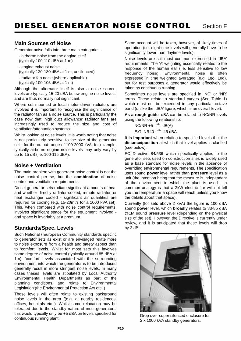
DIESEL GENERATOR NOISE CONTROL Section F
F10
Main Sources of NoiseGenerator noise falls into three main categories -
- airborne noise from the engine itself(typically 100-110 dBA at 1 m)
- engine exhaust noise(typically 120-130 dBA at 1 m, unsilenced)
- radiator fan noise (where applicable)(typically 100-105 dBA at 1 m)
Although the alternator itself is also a noise source,levels are typically 15-20 dBA below engine noise levels,and are thus normally not significant.
Where set mounted or local motor driven radiators areinvolved it is important to recognise the significance ofthe radiator fan as a noise source. This is particularly thecase now that ‘high duct allowance’ radiator fans areincreasingly used to reduce the size and cost ofventilation/attenuation systems.
Whilst looking at noise levels, it is worth noting that noiseis not particularly sensitive to the size of the generatorset - for the output range of 100-2000 kVA, for example,typically airborne engine noise levels may only vary byup to 15 dB (i.e. 100-115 dBA).
Noise + VentilationThe main problem with generator noise control is not thenoise control per se, but the combination of noisecontrol and ventilation requirements.
Diesel generator sets radiate significant amounts of heatand whether directly radiator cooled, remote radiator, orheat exchanger cooled - significant air quantities arerequired for cooling (e.g. 15-20m3/s for a 1000 kVA set).This, when compared with noise control requirements,involves significant space for the equipment involved -and space is invariably at a premium.
Standards/Spec. LevelsSuch National / European Community standards specificto generator sets as exist or are envisaged relate moreto noise exposure from a health and safety aspect thanto ‘comfort’ levels. Whilst for most sets this involvessome degree of noise control (typically around 85 dBA at1m), ‘comfort’ levels associated with the surroundingenvironment into which the generator is to be introducedgenerally result in more stringent noise levels. In manycases theses levels are stipulated by Local AuthorityEnvironmental Health Departments as part of theplanning conditions, and relate to EnvironmentalLegislation (the Environmental Protection Act etc..)
These levels will often relate to existing backgroundnoise levels in the area /(e.g. at nearby residences,offices, hospitals etc..). Whilst some relaxation may betolerated due to the standby nature of most generators,this would typically only be +5 dBA on levels specified forcontinuous running plant.
Some account will be taken, however, of likely times ofoperation (i.e. night-time levels will generally have to besignificantly lower than daytime levels).
Noise levels are still most common expressed in ‘dBA’requirements. The ‘A’ weighting essentially relates to theresponse of the human ear (i.e. less sensitive to lowfrequency noise). Environmental noise is oftenexpressed in time weighted averaged (e.g. Lgo, Leq),but for test purposes a generator would effectively betaken as continuous running.
Sometimes noise levels are specified in ‘NC’ or ‘NR’terms. These relate to standard curves (See Table 1)which must not be exceeded in any particular octaveband (unlike the ‘dBA’ figure, which is an overall level).
As a rough guide, dBA can be related to NC/NR levelsusing the following relationship:
NC/NR +5 –– dB(A)
E.G. NR40 –– 45 dBA
It is important when relating to specified levels that thedistance/position at which that level applies is clarified(see below).
EC Directive 84/536 which specifically applies to thegenerator sets used on construction sites is widely usedas a base standard for noise levels in the absence ofoverriding environmental requirements. The specificationuses sound power level rather than pressure level as aunit (the intention being that the measure is independentof the environment in which the plant is used - acommon analogy is that a 2kW electric fire will not tellyou the temperature a space will reach unless you knowthe details about that space).
Currently (for sets above 2 kVA) the figure is 100 dBAsound power level, which broadly relates to 83-85 dBA@1M sound pressure level (depending on the physicalsize of the set). However, the Directive is currently underreview, and it is anticipated that these levels will drop by 3 dB.
-Ω-
-Ω-
Drop over super silenced enclosure for2 x 1000 kVA standby generators.

DIESEL GENERATOR NOISE CONTROL Section F
F11
NR LEVELSOCTAVE BAND CENTRE FREQUENCY (Hz)
63 125 250 500 1K 2K 4K 8KNR100 125 119 105 102 100 98 96 95NR 95 111 105 100 97 95 93 91 90NR 90 107 100 96 92 90 88 86 85NR 85 103 96 91 87 85 83 81 80NR 80 99 91 86 82 80 78 76 74NR 75 95 87 82 78 75 73 71 69NR 70 91 83 77 73 70 68 66 64NR 65 87 78 72 68 65 62 61 59NR 60 83 74 68 63 60 57 55 54NR 55 79 70 63 58 55 52 50 49NR 50 75 65 59 53 50 47 45 43NR 45 71 61 54 48 45 42 40 38NR 40 67 57 49 44 40 37 35 33NR 35 63 52 45 39 35 32 30 28NR 30 59 48 40 34 30 27 25 23NR 25 55 44 35 29 25 22 20 18NR 20 51 39 31 24 20 17 14 13NR 15 47 35 26 19 15 12 9 7NR 10 43 31 21 15 10 7 4 2
NR LEVELSOCTAVE BAND CENTRE FREQUENCY (Hz)
63 125 250 500 1K 2K 4K 8KNC 70 83 79 75 72 71 70 69 68NC 65 80 75 71 68 66 64 63 62NC 60 77 71 67 63 61 59 58 57NC 55 74 67 62 58 56 54 53 52NC 50 71 64 58 54 51 49 48 47NC 45 67 60 54 49 46 44 43 42NC 40 64 57 50 45 41 39 38 37NC 35 60 52 45 40 36 34 33 32NC 30 57 48 41 35 31 29 28 27NC 25 54 44 37 31 27 24 22 21NC 20 51 40 33 26 22 19 17 16NC 15 47 38 29 22 17 14 12 11
Table 1

DIESEL GENERATOR NOISE CONTROL Section F
F12
Table 2 shows the typical ambient levels for both daytime and night time in central London, suburban andcountry conditions.
Noise Climate Noise ClimatedB(A) dB(A)
Group Location 08.00-18.00h 01.00-06.00h
A Arterial roads with many heavy 80-68 68-50vehicles and buses (kerbside).
B i) Major roads with heavy traffic and buses. 75-63 61-48ii) Side roads within 15-20m of a road in
group A or B(I)
C i) Main residential roads 70-60 54-44ii) Side roads within 20-50m of heavy
traffic routesiii) Courtyards of blocks of flats screened
from direct view of heavy traffic.
D Residential roads with local traffic only. 65-57 52-44
E i) Minor roads 60-52 48-43ii) Gardens of houses with traffic routes
more than 100m distant
F Parks courtyards and gardens in 55-50 46-41residential areas well away from traffic routes
G Places of few local noises and only very 50-47 43-40distant traffic noise
Point
Line
Plane
Distance
So
und
leve
l dB
3dB
0dB3dB
6dB
c a b
Attenuation with distance from various sourcesThe slope represents 0.3 and 6dB per doubling of distance

DIESEL GENERATOR NOISE CONTROL Section F
F13
Noise Legislation in Other CountriesFrance - 85 dBA at 1 metre for any construction site
within 50 metres of a residential area.
Germany - 80 dBA at 1 metre for a generating set onany construction site within 50 meters of aresidential area.
Sweden - Swedish standard SEN 590111 sets a limit of85 dBA. This is applied for the purpose ofreducing the exposure of employed personswhere the level of sound is continuous foreight hours in any one day. Hearingprotection must be used when the levelexceeds 85 dBA.
USA - The OSHA Safety and Health standards sets a limit of 90 dBA for an eight hourexposure, 95 dBA for four hours and 100dBA for two hours.
Typical Noise ‘Climates’Where a noise level is not specified, but it is felt thatsome attenuation may be required, an assessment of adesirable level can be made by relating to the prevailingbackground noise (this is broadly what current UKenvironmental legislation does). It is important torecognise that background noise would not generallyinclude noise ‘peaks’ from (e.g.) passing traffic, trains orplanes. More distant (e.g. motorway) traffic noise may berelevant if it effectively represents a more continuoustype of noise. Table 2 indicates some typical ambientnoise levels, and also shows the variation betweendaytime and night-time.
As a rough guide (in the absence of other specifiedlevels) standby generator noise should equal or be up to5 dBA less than the background noise at the most likelynoise sensitive points. Note that peak lopping, CHP,landfill gas and other ‘non-standby’ sets will generallyneed designing to a lower level dependant on times ofoperation.
Relating the Specification Level toGenerator NoiseHaving been given or estimated a spec. level it isimportant - as stated earlier - to establish where theselevel(s) apply - at what distance(s) and position(s) inrelation to the generator set. If there is a choice in thesiting of the set this can have a significant effect on theattenuation required. If, for example, the level applies ata particular boundary then siting the generator remotelyfrom that boundary will allow distance attenuation toassist in establishing a more realistically achievablenoise level at the set position.
Similarly, the effect on any building(s)/topography on sitebetween the generator position and spec. point should beconsidered. The resultant ‘screening’ attenuation can bevaluable in assisting to achieve the spec. level required.
It is important that such factors are taken into accountwhen specifying generator noise levels - often the latterare presented in terms of a level at 1 m from theset/package/plant-room without allowing for ‘natural’attenuation. The resultant spec. level - apart from beingunrealistic - can often be very costly (if it is notimpossible) to achieve.
In most situations the main ‘natural’ attenuation availableis that due to distance (as the sound waves radiatefurther from the source the radiating area increases andso sound pressure level reduces). Whilst the commonlyused formula for distance attenuation is “6 dB drop withdoubling of distance” this must be used with caution.This is because the formula relates to radiation from apoint source. At closer distances a generator set(whether enclosed or via plant room louvres) effectivelyrepresents a plane source. Nearer a plane source thereduction from attenuation due to distance isconsiderably less than for a point source. (See figure 3)
The following corrections should be used as anapproximate guide for attenuation due to distance.
Up to 10m 1 dB per meter(i.e. 5m = -5 dB, 10m = -10 dB etc.)
Above 10m, apply 6 dB per doubling of distance,i.e. 20m = -16 dB, 40m = -22 dB etc..
The following table summarises the attenuation due todistance:
Distance (m) Attenuation (dB)
1 -1
3 -3
5 -5
7 -7
10 -10
15 -13
20 -16
30 -19
40 -22
50 -23
100 -29
Also see Page F12.

DIESEL GENERATOR NOISE CONTROL Section F
F14
Application Notes
Outdoor locations, acousticallyenclosedIn this situation the acoustic enclosure performs twomain functions - providing a secure weatherproofhousing for the generator, and the required level ofattenuation.
The enclosure and its ancillaries can take various forms,but all contain a number of key features:
- The enclosure itself. Typically a one piece ‘drop over’style unit with access doors as appropriate or a selfcontained package unit.
- The attenuated ventilation system, comprising inletand outlet louvres/attenuators, with dampers/gravityflap units as required.
- The exhaust silencing system.
It is important that the generator set itself is isolated fromthe enclosure components, to minimise vibrationtransmission. This is achieved using anti-vibrationmounts under the set itself, a flexible connector betweenthe radiator and discharge attenuator, and a flexiblebellow in the exhaust system (plus flexible links in fuellines etc.).
Fig. F5 shows a fairly typical layout. Although this showsthe enclosure/set sitting on a concrete plinth, in manysituations ‘packaged’ units are supplied - for examplewhen the unit sits on I section steel joists or on raisedconcrete piers. For these applications the enclosure hasa separate steel base, or the set is supplied in a‘containerised’ unit.
Noise Levels
For arrangements such as this noise levels of 70-85 dBAat 1m are readily achievable for most sets. Lower levelsdown to 60/65 dBA at 1m can be achieved but requirespecial attention to the ventilation attenuation andexhaust systems. With regard to the latter, noiseradiating from the casings of external silencers can beproblematical for lower noise levels, requiring them to belocated inside the enclosure, and thermally lagged tocontrol radiated heat.
It should also be noted that - at lower noise levels -regenerated noise at weather louvres can cause highfrequency problems.
Very Low Noise
Fig. F6 shows one arrangement for an enclosure to meetlower noise specs. This arrangement can also be usedwhere ‘cleaner lines’ are required for aesthetic reasons -the conventional ‘3 box’ arrangement of an enclosurewith external attenuators and roof mounted exhausts isnot always acceptable to architects and planners.
This particular example also shows an acousticallytreated steel base - the ‘package’ approach previouslyreferred to.
60 dBA at 1 m generally represents the lowest practicallyachievable level for the ‘single enclosure’ approach. If alower level is required (and they are often asked for !)and it is required at 1 m, then the ‘extreme’ treatment ofa ‘double’ (inner and outer) enclosure - with two stageattenuation and elaborate exhaust systems - is required.It is important to recognise that not only is the cost ofsuch treatment very significant, but that the increasedspace (and weight) involved can make it impractical.
Indoor plant-room locationsAlthough the main principles of acoustic enclosuredesign and layout broadly apply to plant-room situations,the latter often have particular design difficulties broughtabout by building layout and space constraints.
A fairly typical situation is that of the generator(s) locatedbelow ground level in an urban office complex (Fig. F7).
If we consider ventilation aspects first, as these are oftenproblematical in their own right (without the complicationof noise control), particularly on multiple set installations.
Ventilation
Ventilation paths can be somewhat restricted (due tolimited shaft areas available to/from ground level), andan added complication is that frequently only one outsidewall/well is available. This can cause problems in termsof getting an acceptable airflow pattern across the set(i.e. avoiding ‘dead’ spots at the alternator end) and -more particularly - in terms of possible recirculation ofhot air between the air discharge and air inlet. This leadsto overheating (and eventual shutdown) of the generatorset, and needs controlling using barriers in/aroundventilation spaces.
These problems are exacerbated with the introduction ofnoise control. Such ventilation paths invariably terminateat street level, where relatively severe noise constraintswill apply (55-60 dBA at pavement level is a typicalrequirement).
Attenuators
To achieve the high degree of attenuation required alongwhat is unlikely to be a ‘straight through’ type ventilationpath often means that conventional ‘cased’ attenuatorunits cannot be used. One proven approach is toconstruct acoustic plenum chambers from acousticpanels, creating the attenuators therein using acousticsplitter elements (Fig. F8).
Noise via the ventilation system is often the most difficultproblem to solve, but it is by no means the onlyconsideration. Noise breakout to adjacent areas via theplant-room walls/ceiling slab can also be a problem.Whilst the attenuation achieved through standardwall/slab constructions is normally appreciable, it mustbe remembered that internal noise levels for (say) officeareas are considerably lower than might be required atthe external louvres.
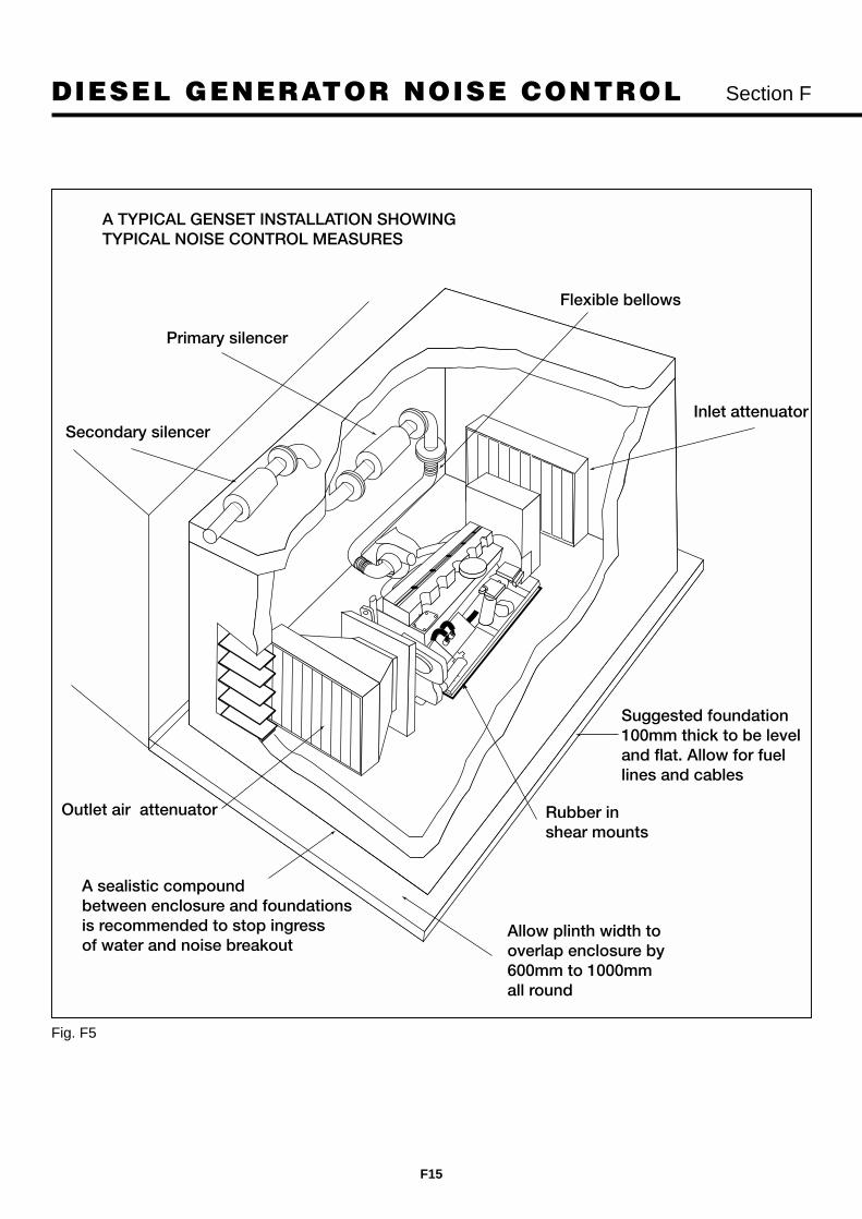
DIESEL GENERATOR NOISE CONTROL Section F
F15
A TYPICAL GENSET INSTALLATION SHOWINGTYPICAL NOISE CONTROL MEASURES
Primary silencer
Flexible bellows
Inlet attenuator
Rubber in shear mounts
Allow plinth width to overlap enclosure by600mm to 1000mm all round
Suggested foundation 100mm thick to be level and flat. Allow for fuel lines and cables
Outlet air attenuator
A sealistic compoundbetween enclosure and foundations is recommended to stop ingress of water and noise breakout
Secondary silencer
Fig. F5

DIESEL GENERATOR NOISE CONTROL Section F
F16
GENERATING SETS – NOISE REDUCTION RECOMMENDATIONS
With acoustic enclosure 60-75 DBAInternal attenuators (typical)Internal exhaust silencing @1M
Lagging
Sound attenuator
Air inAir out
Additional extract motor fan recommended for use in high ambient temperaturesexceeding 30°C
Fig. F6 Arrangement to meet low noise specifications.

DIESEL GENERATOR NOISE CONTROL Section F
F17
Exhaust flue
Offices
OfficesGround level
Basementplant room
Exhaust run to roof shouldbe through sound attenuated flue ducting
GENERATION SETS – NOISE REDUCTION RECOMMENDATIONS
Fig. F7 Generator located below ground level.

DIESEL GENERATOR NOISE CONTROL Section F
F18
Sound attenuators inside a plant room for two 1256kVA CP1250-5 sets
1000kVA Super Silenced (75dBA@1m) automatic standby set for major hypermarket chain warehouse

DIESEL GENERATOR NOISE CONTROL Section F
F19
Ground floor
Basement
Sound attenuator
GENERATING SETS – NOISE REDUCTION RECOMMENDATIONS
Additional extract motor fan recommended for use in high ambient temperaturesexceeding 30°C
Plant-room locations (cont.)Thus with a plant-room noise level of (say) 105 dBA, andtypical reductions through walls of 25-35 dBA, andthrough a ceiling slab of 30-40 dBA, resultant levels inadjacent areas would be 70-80 dBA (the other side ofthe walls) and 65-75 dBA (above the slab). Whilst areasto either side of the generator room may well be non-critical (e.g. if they are other plant-rooms), areas aboveare usually office/reception areas, where maximumtolerable levels are likely to be 45-55 dBA.
Room Treatment
To significantly improve noise breakout levels - eitherinvolves fitting an indoor style acoustic enclosure aroundthe set (space/access problems often preclude this) oradding acoustic panel wall/ceilings to the room. It isimportant to recognise that such treatments are differentto simple absorptive lining treatments. These latter,which are applied direct onto the surfaces involved,simply introduce areas of adsorption into the area ,reducing the reverberant noise level in the plant-room.
Whilst this reduction (typically about 5 dBA) in internalplant-room noise level will also manifest itself as areduction in noise breaking through to adjacent areas,such treatments do not significantly improve the soundinsulation of the wall/slab treated.
By using secondary acoustic panel treatments spacedoff the wall/slab concerned the noise breakout levelcan be reduced by 10-15 dBA. On acoustic ceilings it is
important to minimise rigid fixings to the slab, usingspring hangers where possible.
Plant-Room Doors
One final (but critical) point concerning noise breakoutfrom the generator plant-room is that any access doorsshould generally be of the acoustic type (of appropriateperformance), and consideration must be given to noisebreakout via pipe/cable penetrations - particularlytrenches which often pass under dividing wall lines.
Exhaust system
Turning now to the exhaust system - this is oftenoverlooked somewhat on the basis this is frequentlypiped via a flue to roof level, and so assumed that‘residential’ grade silencing is adequate. Whilst this maybe acceptable in many cases, consideration should begiven to noise from the flue itself (Fig. F7). Even withprimary silencing carried out in the generator room,residual noise levels inside the exhaust riser are stillrelatively high (possibly 90-100 dBA), and if the risershaft is constructed from lighter weight materials, or hasaccess doors/panels then noise breakout to low noiselevel offices can be a problem. In terms of noise at theexhaust termination, this should obviously relate to spec.levels at (say) surrounding buildings - or noise breakingback into the building served. For particularly low levelsregenerated noise caused by the relatively high pipevelocities can be a problem.
Fig. F8 Acoustic plenum chamber silencing.

DIESEL GENERATOR NOISE CONTROL Section F
F20
Two 1000kVA silenced standby sets with ‘drop over’ enclosures at roof top level eliminate many problems but create others
Four 1250kVA automatic starting, auto sync sets in specially adapted containers reduce noise levels down to75dB(A)@1m Photo: Courtesy of EuroTunnel - Transmanche link

DIESEL GENERATOR NOISE CONTROL Section F
F21
6m (20ft) silenced module forms part of an 18m (60ft) installation containing a 2000kVA standby generator
Modular construction cuts time factor down significantly on site.

DIESEL GENERATOR NOISE CONTROL Section F
F22
Completed installation with roof mounted radiators and exhaust system.
Large containerised generators for isolated locations provide a convenient package for transportation and fastinstallation.

DIESEL GENERATOR NOISE CONTROL Section F
F23
Roof top locationsNot all generators are located in basements, however,and mention should be made of units in higher level - orrooftop - plant-rooms . The main additional problem hereis noise breakout through the floor slab to areas below(which are generally noise sensitive). This can becontrolled by full floating floors, although these are often problematical with large heavy items such asgenerator sets.
A more practical approach is to have the generator seton plinths (using suitable high performance anti-vibrationmountings) with an ‘infill’ acoustic floor for theintermediate spaces.
Table 8 summarises plant-room treatments for a range ofexternal noise levels.
DIESEL GENERATOR INSTALLATIONS - PLANT ROOM. ELEMENTS RELATIVE TO NOISE LEVELS (GUIDANCE ONLY)
Noise Level Louvres/Attenuators Doors Walls Exhaust Comments
85-90 Acoustic Louvres Solid Core Timber Blockwork Single Residential
75-80 Attenuators Acoustic Cavity Blockwork Residential + (Standard) (plastered/sealed) Secondary or
high performance
65-70 Attenuators Acoustic Cavity Blockwork 2 residential + (Heavy Duty) (plastered/sealed) secondary or
high performance+ secondary
55-60 Attenuators, Acoustic inner Cavity Blockwork 4 Silencer System Internal Enclosurepossibly with acoustic + outer + acoustic lining - possible option.louvres or lined bend(s). Air generated Attenuators may need noise atpanelwork casings. louvres needs
consideration
55 or less Untypical and often impractical. Requires special consideration.
Table 8

DIESEL GENERATOR NOISE CONTROL Section F
F24
Units of Sound MeasurementSound power level (environmental noise) = dB(A) / 1pw
Sound pressure level (at operators ear) = dB(A)
The ‘regulated’ levels of sound are unlikely to beadequate for standby generators located near tosensitive environments such as hospitals, offices, publicplaces and residential districts.
Measurement of Sound - DecibelsPressure Measurement
Each crest of a sound wave arriving at the ear causesthe eardrum to flex inward. A powerful wave with highcrests will cause more eardrum flexure than a weakerwave and so the brain perceives one sound as beingmore loud than another.
The diaphragm of a microphone behaves exactly thesame way as the eardrum when struck by a sound wave.A microphone, augmented by amplifiers, rectifiers and ameasuring instrument can thus measure the soundpressures of different sound waves and thereforedetermine the intensity of the sound.
Measurements have shown that a barely audible soundhas an intensity of one picowatt (one million-millionth ofa watt) per square meter, whereas a jet engine at arange of 25 meters delivers 100 w/m2. The roar of the jetengine is thus 1014 times more intense!
Logarithmic Decibel ScaleAbsolute values of sound pressure and sound intensitycan only be expressed in long and cumbersomenumbers. The use of a logarithmic scale makes it mucheasier to express the levels in convenient terms. The unitof measurement on this scale is called the ‘bel’ afterAlexander Graham Bell. In practice, for the sake of beingable to work with whole numbers, it is customary tomultiply values in bels by 10 and to express the values indecibels (dB).
Fig. F10 Attenuation in dB with ‘A’ Filter
Fig. F9 Frequency Octave Band Noise Ambients
Frequency Octave Band Noise Ambients
dB
A
80
70
60
50
40
30
20
10
0
63 125 250 500 1000 2000 4000 6000
Frequency - Hz
Country Night
Country Day
Suburb Day
London Night
London Day

DIESEL GENERATOR NOISE CONTROL Section F
F25
Logarithmic Decibel Scale (cont.)The decibel rating of a given sound indicates the level ofsound pressure or intensity at which it lies. The thresholdof hearing (Fig. F10) at a frequency of 1000 Hz gives thestarting point of 0 dB, and the threshold of pain isreached somewhere between 120 and 130 dB.
But we have to be careful with decibels, logarithmicnumbers cannot be added together in the same way asordinary numbers. Thus a rise of 3 dB corresponds to adoubling of sound intensity, while a rise of 10 dB from agiven level means that the sound intensity becomes 10times higher than before.
Frequency FilterAlthough two sound waves with different frequenciesmay have the same sound pressure, we do notnecessarily hear them as loud. This is because the ear ismost sensitive in the 2000 to 4000 (2 - 4 kHz) range,while lower frequencies in particular are not picked up aswell. Allowances are made for this non-uniformsensitivity when noise levels are measured. Most soundlevel meters therefore have built in filters. They imitatethe ear by attenuating the lower frequencies therebyobtaining physiologically realistic noise level readings.
There are several different types of frequency filter, butthe most widely used one is the ‘A’ filter. This is standard equipment when measuring traffic noise, forexample. Readings obtained with such meters areexpressed in dB(A), the letter in brackets indicating thefilter type used.
Octave Band AnalysisA measurement of true loudness requires, not only singlereading of a noise-level meter, but at least eight singlereadings of the sound level, each reading being anindication of the noise power in part of the frequencyrange encompassed by the noise. Some simplearithmetical manipulation of the eight values obtainedthen gives the true loudness, a figure that would agreewith the subjective reactions of a panel of listeners.
Most common noises consist of a mixture of separatefrequencies and are not just a single frequency. Ameasurement of the distribution of the sound energy canbe given by a sound level meter, preceded by suitableelectronic circuits that separate the total frequency bandinto eight separate sections and allows the noise energyin each section to be separately determined. These arethe eight readings known as octave band analysis. SeeFigs. F9 and F11.
Fig. F11
How loud is ‘too loud’It is accepted that the ‘upper threshold’ of sensitivity tonoises varies from person to person: variations of ±20dB have been noted. The composition of noises in termsof frequency is another variable factor, and the effects ofdifferent parts of the noise spectrum on humanphysiology are well documented. The predominantfrequencies in a noise are of fundamental importancewhen selecting the means of controlling noise.
Normal industrial acoustic-measurements systemsincorporate a weighting which balances out sound interms of human response at different frequencies. Of thethree principal weighting networks (A,B and C), Aequates so well with the subjective response of averagepeople that many noise problems are assessed in termsof the A-weighted decibel, denoted dB(A).
Specifying sound - Decibels and noiseratingsDecibels
Sound levels in decibels should be defined by one of thethree principal frequency filters, namely A, B or C. Forexample, most sound levels, if intended to relate directlyto human hearing should be defined in dB(A) terms.
But dB(A) figures by themselves are valueless untilapplied to a distance, for example 83 dB(A) at 1 metre.
This is essentially the ‘average’ value of decibel readings at specific frequencies taken across an octaveof eight frequency bands, say from 63 to 8000 Hz (seeFigs. F11 and F12).
20 75 150 300 800 1200 2400 480075 150 300 600 1200 2400 4800 9600
63 125 250 500 1K 2K 4K 8K
Hz Frequency bands (full width) Octave
Typical Octave on Centre Frequency

DIESEL GENERATOR NOISE CONTROL Section F
F26
Noise Rating (NR terms)A further and lesser used system to define the noiselevel for a generating set is the NR (Noise Rating)method as illustrated in Figure F13.
In this case the specification could call for an NR40rating at 30 metres for example. The NR ratings are anarbitrary scale and are used as a guide to the‘annoyance’ factor that a certain level of noise will createin the minds of those exposed to the irritation.
Scales for dB(A) levels and the eight frequency levels(as in Fig. F11) are the accepted international standardsfor noise measurement. The NR ratings on the RH sideof the diagram, however, are ‘values of annoyance’. Theaccompanying table gives an indication of possibleresults using this method.
Sound of equal loudness but of different frequency donot produce equal degrees of irritation, high frequencynoises being much more ‘annoying per decibel’ than anequal lower frequency noise. Instruments do not takethis into account but as Figure 13 shows, graphicalillustration does.
Each curve is a contour of ‘equal annoyance’, indicatingthe sound intensity required at each frequency toproduce the value of annoyance mark at the right handside of the curve.
To test, readings of sound intensity, in each of the eightoctave bands, can be taken by a sound level meterpreceded by an octave filter and plotted on the curvesheet. The points should then be joined together bystraight lines. The resultant plot gives this noise a ‘NoiseRating’, the rating being taken at that point of the curveimmediately above the highest plotted rating.
Frequency Hz 63 125 250 500 1K 2K 4K 8K dBA@ 1m from radiator & exhaust 88 89 98 94 91 90 98 105@ 1m from side 78 92 92 93 96 89 92 105
Frequency Hz 63 125 250 500 1K 2K 4K 8K dBA@ 1m from radiator & exhaust 83 87 71 65 61 58 60 84@ 1m from side 72 75 67 63 61 55 55 76@ 7m from radiator & exhaust 77 73 66 62 56 52 57 76@ 7m from side 68 67 66 59 56 52 49 72
200 kW generating set in Silencing Enclosure
Examples of noise levels of generating sets on full load
Unsilenced 200 kW generating set
Fig. F13
Fig. F12

DIESEL GENERATOR NOISE CONTROL Section F
F27
For anyone to specify noise levels below - say NR40 - itis necessary for them to specify the distance away fromthe generating set that the readings are taken. Forinstance, a generator 30 m away will probably comply,but not 15m away. As an approximate guide to “noiseannoyance” levels, the following NR ratings are indicatedand apply to Figure F13.
NR40 and below - No observed reaction
NR40 to NR50 - Few complaints
NR45 to NR55 - Main sector for complaints
NR50 to NR60 - Legal action possibly threatened
NR65 and above - Action taken
By comparison with actual environments (Figure F15)illustrates NR ratings against specific locations.
Fig. F15 NR - Noise Rating Table
Table. F16 Decibel Rating - (dB) - Environments
Noise Rating Type of Room
Number15 Broadcasting Studio20 Concert Hall or Theatre25 Bedroom, large conference room,
classroom, TV studio30 Living room, small conference room,
hospital, church library40-50 Private office, gymnasium, restaurants50-55 General office65-75 Workshops
Decibels dB
Threshold of hearing at 1kHz 0Studio for sound pictures 20Residence - no children 40Conversation 60Heavy Traffic 80Underground train 100Close to pneumatic drill 120Gas turbine engine at 30m (damage to ears) 140Rocket engine at 30m (panting of stomach) 160
110dB in vicinity of airportsLogarithmic scale of measurementSound of 1 watt at 0.3m distance = Intensity of 104 (painful to ears)Each step of 10 decibels = Increase of intensity of 10 timesTherefore 20 dB = 100 times the minimumTherefore 30 dB = 1000 times the minimum
Fig. F14

DIESEL GENERATOR NOISE CONTROL Section F
F28
Sound Reduction - The choiceThe choice of reducing sound levels on generating setsfalls into a number of categories. Standard sheet metal weather protection - for use
outdoors, small reduction on mechanical noise, butradiator noise is unaffected. Exhaust noise can beconsiderably reduced.
Enclosing the generator in a specially designedsound proof canopy with air inlet and outlet soundattenuators - for use outdoors.
Standard soundproof enclosures will give a reductionbetween 12 and 30 dBA. A further reduction can beachieved by increasing the density of the barrier andincreasing the length of air inlet and outlet attenuatoron specially designed enclosures for specific duties.
Installing the generating set in a normal brick roomwith air inlet and outlet sound attenuators andacoustic doors. High reverberant noise level withinthe plant room but effective reduction of the noiselevels to outside.
Installing the generating set in a room lined withsound absorbing material and with air inlet and outletsound attenuators.
Noise inside plant room reduced and considerablereduction on noise level to outside. Installing an enclosed generating set in a room. The
set is enclosed in a specially designed sound proofcanopy with integral air inlet and outlet soundattenuators.
Low noise levels inside and outside of room. Other means of reducing noise. These remote
radiators (to spread the noise over selected areas)and the use of cooling towers, although in both casesthe generating set noise, even without the radiatorwill be relatively high.
The noise level of an unsilenced or silenced generatingset as heard by the listener depends on the followingfactors
i) The level of the noise at its source
ii) The level of ambient background noise
iii) The hearing ability of the listener
iv) The distance of the listener from the source of thenoise
Fig. F17 Sound Intensity Examples
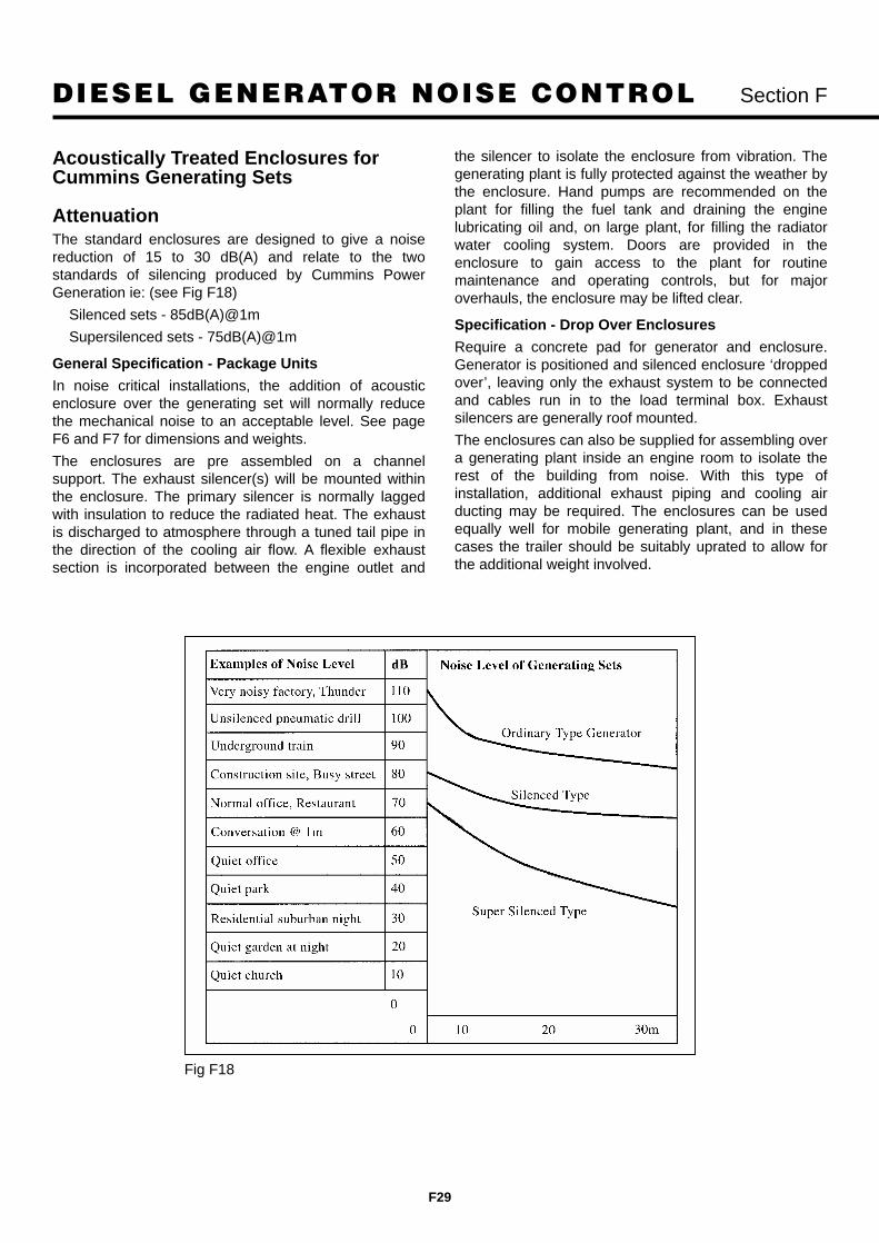
DIESEL GENERATOR NOISE CONTROL Section F
F29
Acoustically Treated Enclosures forCummins Generating Sets
AttenuationThe standard enclosures are designed to give a noisereduction of 15 to 30 dB(A) and relate to the twostandards of silencing produced by Cummins PowerGeneration ie: (see Fig F18)
Silenced sets - 85dB(A)@1m
Supersilenced sets - 75dB(A)@1m
General Specification - Package Units
In noise critical installations, the addition of acousticenclosure over the generating set will normally reducethe mechanical noise to an acceptable level. See pageF6 and F7 for dimensions and weights.
The enclosures are pre assembled on a channelsupport. The exhaust silencer(s) will be mounted withinthe enclosure. The primary silencer is normally laggedwith insulation to reduce the radiated heat. The exhaustis discharged to atmosphere through a tuned tail pipe inthe direction of the cooling air flow. A flexible exhaustsection is incorporated between the engine outlet and
the silencer to isolate the enclosure from vibration. Thegenerating plant is fully protected against the weather bythe enclosure. Hand pumps are recommended on theplant for filling the fuel tank and draining the enginelubricating oil and, on large plant, for filling the radiatorwater cooling system. Doors are provided in theenclosure to gain access to the plant for routinemaintenance and operating controls, but for majoroverhauls, the enclosure may be lifted clear.
Specification - Drop Over Enclosures
Require a concrete pad for generator and enclosure.Generator is positioned and silenced enclosure ‘droppedover’, leaving only the exhaust system to be connectedand cables run in to the load terminal box. Exhaustsilencers are generally roof mounted.
The enclosures can also be supplied for assembling overa generating plant inside an engine room to isolate therest of the building from noise. With this type ofinstallation, additional exhaust piping and cooling airducting may be required. The enclosures can be usedequally well for mobile generating plant, and in thesecases the trailer should be suitably uprated to allow forthe additional weight involved.
Fig F18

DIESEL GENERATOR NOISE CONTROL Section F
F30
Sound Reduction - Site ConditionsAs noise is highly modified by its surroundings, it isessential to know the ultimate location of the generatingplant. This usually falls into separate categories:Installed in a plant room or external to a building in theopen. The following questions need to be answered:
1) What is the existing noise and vibration climate ofthe site?
2) What is the maximum noise level allowable in thesurrounding area?
3) Is the predetermined noise level realistic?
4) If an existing plant room, what is the insulating andisolating performance of the building?
5) Is there sufficient ventilation for the plant?
6) What is the permissible floor loading of the site?
Existing Noise on Site (See Table 2 pageF12 and Fig. F17 page F28)It is always advisable to measure the existingbackground noise level before installation of theequipment, as it is pointless to attempt to attempt toreduce the noise levels below those already existing.There are, however, exceptions to this in certain parts ofthe country, where there is an obvious attempt by localauthorities to reduce the overall noise pollution. Althoughmany existing sites are extremely noisy during workinghours, they may be extremely quite at night-time and thisshould be borne in mind, particularly if the standby plantmay be required to run outside normal hours.
Maximum Noise LevelCorrection for the type of district in the neighbourhood ofthe measuring position.
1) Rural residential. -5dBA
2) Suburban, little road traffic. 0
3) Urban residential. +5bBA
4) Predominantly residential urban but some light industry or main roads +10dBA
5) General industrial (between 4 and 6) +15dBA
6) Predominantly industrial area with few dwellings +20dBA
Correction of time of day
Weekdays only
08.00 - 18.00 +5dBA
22.0 - 17.00 -5dBA
Other times 0
If it is known that the noise will occur only during thewinter months, +5dBA is added to the base criterion.
Realistic pre-determined Noise LevelsAs previously pointed out, there is little point inattenuating noise to ridiculously low levels. In certaincases (TV and radio studios, hospitals etc.), very lownoise levels are required but these are generally wellspecified.
In the main, noise levels of 60 dBA are usuallyacceptable for residential areas and to attempt to reducethe noise levels below this figure is costly and can addconsiderably to the size of an installation (a 40 dBAoutlet attenuator can exceed 2m in length)
Insulating and Isolating Properties ofPlant room materials.We should first consider the terms used:
Sound Insulation
This is the reduction in sound energy achieved by astructure separating a noise source from a quiet area.Sound insulation term is only used when a reduction ofairborne sound is involved and implies a net reduction in sound when it is transmitted by walls etc. connectingtwo rooms.
Sound Isolation
A term used for the transmission originating at impactingor vibrating sources, i.e. water hammer in pipework,slammed doors, vibrational excitation originating atmachinery. The ability of a partition to resist impact noiseis dependant on the character of the surface receivingthe energy. The effectiveness of a partition to act as aninsulator is determined by the following parameters:
1) Weight
2) Stiffness
3) Homogeneity and uniformity
4) Discontinuity and isolation
The following list gives some idea of the average SoundReduction index for typical building materials (see alsoFigures 19,20,22,23 and 24)
Doors
Hollow door with 3mm wood panels 15dB42mm solid wood, normally hung 20dB
Glass
3mm 26dB6mm 30dB12mm 33dBDouble glazed units with two6mm panels and 12mm gap 40dB
Plaster
50mm 35dBPlastered breeze block 40dB

DIESEL GENERATOR NOISE CONTROL Section F
F31
Brickwork
100mm unfinished breeze block 20dB110mm brick 45dB220mm brick 45dB350mm brick 50dB450mm brick 55dB
The Sound Reduction Index can be arrived at by thefollowing formula:
Rmean = 20 + 14.5 log10W dB
Where W is the superficial weight in lb/ft2
Plant VentilationAn important factor in specifying noise control equipmentfor diesel generating plant is the need for adequateprovision of air into and out of the plant room orenclosure. As the larger plant (800kW) require acombustion air volume of around 3200 c.f.m. and aradiator throughput of 40 000 c.f.m., this can entail usingquite large attenuators if the pressure drop is to be keptto reasonable figures.
Certain locations may require the air to be ducted in fromthe outside and allow for this in the site survey.
Fig F19
Fig F20

DIESEL GENERATOR NOISE CONTROL Section F
F32
6. Floor LoadingThe acoustic mass law relates the superficial weight of apartition to its transmission loss. In general, for everydoubling of the weight , there is an increase in insulationof about 5dB.
As most acoustic partitions have a weight ofapproximately 41kg/sq.m.(10 lb/ft2,) it can be seen thatthe overall weight of an enclosure can be quite large, i.e.an 2.4m (8 ft) wide by 4.6m (15 ft) long enclosure for a300 kW generator can weigh 4 tons. If you add to thisthe weight of the plant it is easy to see that there will bea considerable floor loading at the site.
There are many factors which can modify the soundlevel on site - either increasing or decreasing the soundpressure level. Amongst these factors are :
Absorption of sound energy in the atmosphere (SeeFig. F21)
Diffraction due to atmospheric gradients oftemperature and wind speed.
Reflections from buildings.
The directivity of the noise.
The addition of one or more sets in a generator room.
Fig F21

DIESEL GENERATOR NOISE CONTROL Section F
F33
Installation of a Closed SetFor the most effective reduction in noise levels, it isrecommended that the installation be isolated and as faraway from working, office and residential quarters aspossible. This may prove impractical on occasions anddoes mean increased costs for cable and fuel pipe runs.
Control cubicles can be located inside the enclosuremounted on the set and for manual electric startversions, this is recommended. For automatic mainsfailure system, the changeover contactors or ATS unitsshould be located as near to the incoming mains aspossible to avoid unnecessary cable runs. Protectedgullies in the plinth are necessary for the output cables.
Sets can be provided with integral fuel tanks or from anexternally mounted day tank with an automatic fueltransfer system from the bulk tank, which isrecommended for the permanent installation. Allowancemust be made for fuel lines to run to and from the enginethrough the concrete plinth. Also check which side of theengine these emerge from.
Ensure that the air inlet and outlet flows are notobstructed, as any restrictions of air flows may lead tooverheating, loss of output and even shutdown.
dB dB10 10
_____1mm Plywood______20 SWG Plain Aluminium_
_____6mm Plywood_____20 _____9mm Plywood_____ 20
____22mm Whitewood________19mm Chipboard____ ___22 SWG Sheet Steel____ ___3mm Glass___________
30 ____50mm Mahogany____ ___16 SWG Sheet Steel____ ___6mm Glass___________ 30____Gypsum Wallboard____ ___9mm Asbestos faced___ ___12mm Glass__________
18 SWG Sheet Steel__19mm Plasterboard____ __Corrugated Aluminium__
Plaster Both Sides40 ___4 x 12mm Gypsum___ __50mm Reinforced concrete 40
Wallboard___125mm Plain Brick______100mm Reinforced concrete
50 ___300mm Plain Brick_____ 50
___50mm x 200mm____blockwork with 100mm gap in between
60 60
Average Sound Reduction Indices For Typical Partitions
Figure F22
Figure F23

DIESEL GENERATOR NOISE CONTROL Section F
F34
Figure F24
ISO container (9m) 30ft unit contains 600kVA emergency generator. Silenced to 75dB(A) at 1m

DIESEL GENERATOR NOISE CONTROL Section F
F35
Drop over supersilenced enclosure for a 3700kVA Prime Power set sits on specially prepared concrete base
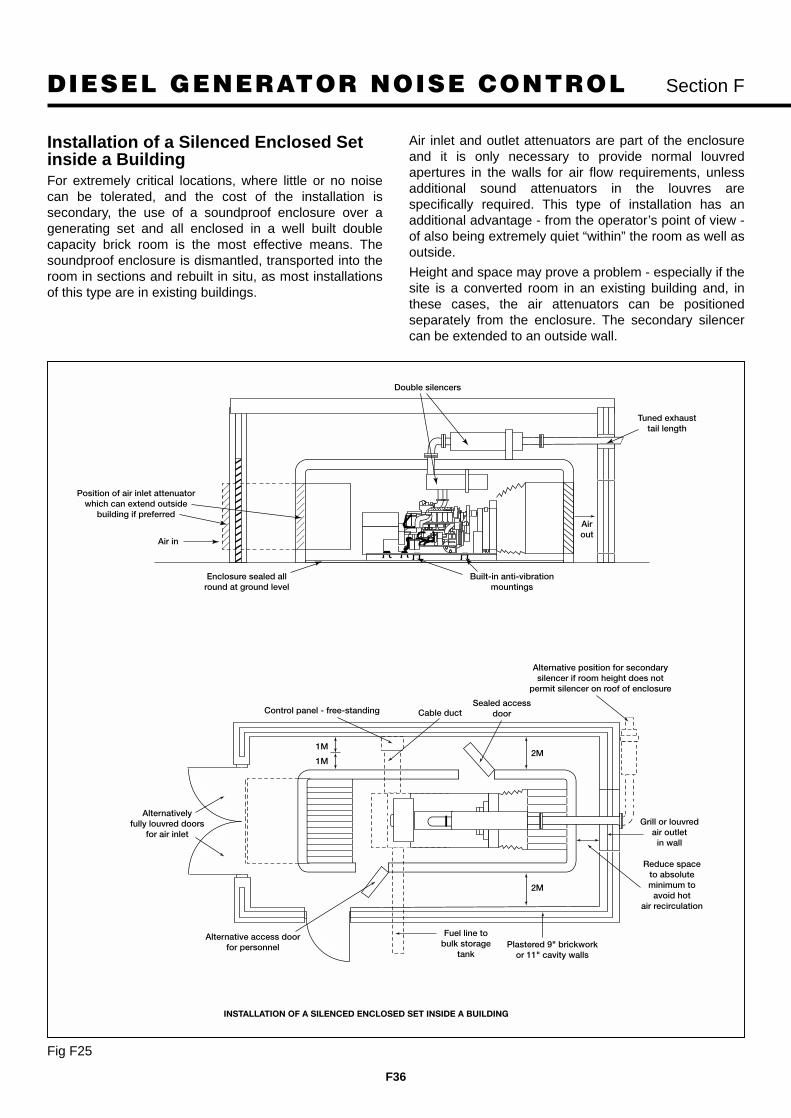
DIESEL GENERATOR NOISE CONTROL Section F
F36
Double silencers
Built-in anti-vibrationmountings
Tuned exhausttail length
Air out
Air in
Enclosure sealed allround at ground level
Alternative position for secondary silencer if room height does not
permit silencer on roof of enclosure
Control panel - free-standing
Alternative access doorfor personnel
Fuel line tobulk storage
tankPlastered 9" brickwork
or 11" cavity walls
Grill or louvredair outlet
in wall
Reduce spaceto absoluteminimum to
avoid hotair recirculation
Sealed access door
Alternativelyfully louvred doors
for air inlet
Cable duct
Position of air inlet attenuator which can extend outside
building if preferred
2M
2M
1M
1M
INSTALLATION OF A SILENCED ENCLOSED SET INSIDE A BUILDING
Installation of a Silenced Enclosed Setinside a BuildingFor extremely critical locations, where little or no noisecan be tolerated, and the cost of the installation issecondary, the use of a soundproof enclosure over agenerating set and all enclosed in a well built doublecapacity brick room is the most effective means. Thesoundproof enclosure is dismantled, transported into theroom in sections and rebuilt in situ, as most installationsof this type are in existing buildings.
Air inlet and outlet attenuators are part of the enclosureand it is only necessary to provide normal louvredapertures in the walls for air flow requirements, unlessadditional sound attenuators in the louvres arespecifically required. This type of installation has anadditional advantage - from the operator’s point of view -of also being extremely quiet “within” the room as well asoutside.
Height and space may prove a problem - especially if thesite is a converted room in an existing building and, inthese cases, the air attenuators can be positionedseparately from the enclosure. The secondary silencercan be extended to an outside wall.
Fig F25

SELECTION CHART Section G
G1
50 Hz RatingsDiesel PoweredGenerating Sets26 kW - 1760 kW
Rating Conditions:
All ratings at 40°C (104°F) ambient temperature.
Ratings: Prime (Unlimited Running Time), applicable for supplying power in lieu of commercially-purchased power.
Prime power is available at a variable load for an unlimited number of hours. A 10% overload capacity is available. Nominallyrated. All in accordance with ISO 8528, ISO 3046, AS 2789, DIN 6271 and BS 5514.
Standby: Applicable for supplying emergency power for the duration of normal power interruption. No sustained overloadcapability is available for this rating. Nominally rated. In accordance with ISO 3046, AS 2789, DIN 6271 and BS 5514.
Prime Rating Standby Model Cummins*2000 Model 1999 Model 2000 Model 1999 Model Engine
kVA kW Prime Prime kVA kW Standby Standby Model32 26 26 DGGC CP30-5T 37 30 30 DGGC CS40-5T B3.3G150 40 40 DGHC CP50-5T 55 44 44 DGHC CS60-5T B3.3G238 30 30 DGBC CP40-5 41 33 33 DGBC CS40-5 4B3.9G52 42 42 DGCA CP50-5 59 47 47 DGCA CS60-5 4BT3.9G164 51 51 DGCB CP60-5 70 56 56 DGCB CS70-5 4BT3.9G270 56 56 DGCC CP70-5 78 62 62 DGCC CS80-5 4BTA3.9G196 77 77 DGDB CP90-5 106 85 85 DGDB CS100-5 6BT5.9G2
106 85 85 DGDB CP100-5 119 95 95 DGDB CS125-5 6BT5.9G2129 103 103 DGEA CP125-5T 145 116 116 DGEA CS150-5 6CT8.3G2153 122 122 DGFA CP150-5T 170 136 136 DGFA CS170-5 6CTA8.3G2185 148 148 DGFB CP180-5T 204 163 163 DGFB CS200-5 6CTA8.3G2204 163 163 DGFC CP200-5T NA NA NA NA 6CTAA8.3G1233 186 186 DFAB CP200-5 259 207 207 DFAB CS250-5 LTA10G2252 202 202 DFAC CP250-5 279 223 223 DFAC CS280-5 LTA10G3NA NA NA NA 313 250 250 DFBF CS300-5 NT855G6315 252 252 DFBF CP300-5 350 280 280 DFBF CS350-5 NT855G6350 280 280 DFCC CP350-5 390 312 312 DFCC CS400-5 NTA855G4NA NA NA NA 425 340 340 DFCE CS450-5 NTA855G6431 345 345 DFEC CP400-5 NA NA NA NA KTA19G3450 360 360 DFEC CP450-5 500 400 400 DFEC CS500-5 KTA19G3511 409 409 DFED CP500-5 576 461 461 DFED CS575-5 KTA19G4575 460 460 DFGA CP575-5 636 509 509 DFGA CS625-5 VTA28G5640 512 512 DFGB CP625-5 706 565 565 DFGB CS700-5 VTA28G5725 580 580 DFHA CP700-5(T) 800 640 640 DFHA CS800-5 QST30G1(6)800 640 640 DFHB CP800-5(T) 891 713 713 DFHB CS900-5 QST30G2(7)939 751 751 DFHC CP900-5(T) 1041 833 833 DFHC CS1000-5 QST30G3(8)
1000 800 800 DFHD CP1000-5 1110 888 888 DFHD CS1100-5 QST30G4936 748 748 DFJC CP900-5 1040 832 832 DFJC CS1000-5 KTA38G3
1019 815 815 DFJD CP1000-5 1132 906 906 DFJD CS1100-5 KTA38G51256 1005 1005 DFLC CP1250-5(T1/2) 1400 1120 1120 DFLC CS1400-5 KTA50G3(6/7)1406 1125 1125 DFLE CP1400-5 1675 1340 1340 DFLE CS1675-5 KTA50G81688 1350 1350 DQKB CP1700-5 1875 1500 1500 DQKB CS1900-5 QSK60G31875 1500 1500 DQKC CP1875-5 2063 1650 1650 DQKC CS2000-5 QSK60G32000 1600 1600 DQKD CP2000-5 2200 1760 1760 DQKD CS2200-5 QSK60G4
*New nomenclature for Year 2000 superceeds 1999 models

TECHNICAL DATA Dimensions & Weights 50 Hz Section G
G2
D
150 Litres sub-base fuel tank (optional)
A 1B O/A
Optionalbatteryremoveforshipment
Optionalcircuitbreakerlocation
A O/A
C O
/A
B1
B3 Series Engines
NOTE 1: Dry and Wet weights of sets do NOT include fuel tank or contents.
Set weights are without sub-base tank. Dimensions and weights are for guidance only.Sub-base tank weights are for single skin tanks.
Do not use for installation design. Ask for certified drawings on your specific application.Specifications may change without notice.
Sub base Sub baseNew Old Length Width Height Set weight Set weight Tank. Dry Tank. Wet
Model Model Engine A mm A1 mm B mm B1 mm C mm D mm kg wet kg dry Weight kg Weight kg26 DGGC CP30 B3.3G1 1667 1600 645 635 1183 300 835 819 150 29940 DGHC CP50 B3.3G2 1760 1600 645 635 1183 300 890 871 150 299

TECHNICAL DATA
G3
26 kW - 45 kW 50 HzB3 Series Engines
Section G
Set output 380-440 V 50 Hz 380-440 V 50 Hz
Prime at 40°C ambient 26 kWe 32.5 kVA 40 kWe 50 kVA
1999 Set Model (Prime) CP30-5T CP50-5T
New Model (Prime) 26 DGGC 49 DGHC
Standby at 40°C ambient 30 kWe 37.5 kVA 44 kWe 55 kVA
1999 Set Model (Standby) CS40-5T CS60-5T
New Model (Standby) 30 DGGC 44 DGHC
Engine Make Cummins Cummins
Model B3.3G1 B3.3G2
Cylinders Four Four
Engine build In-line In-line
Governor/Class Mechanical Mechanical
Aspiration and cooling Natural aspiration Turbocharged
Bore and stroke 95 mm x 115 mm 95 mm x 115 mm
Compression ratio 18.2:1 17.0:1
Cubic capacity 3.26 Litres 3.26 Litres
Starting/Min °C Unaided/4°C Unaided/4°C
Battery capacity 126 A/hr 126 A/hr
Nett Engine output Prime 31 kWm 45 kWm
Nett at flywheel Standby 34 kWm 49 kWm
Maximum load acceptance single step 100% 100%
Speed 1500 rpm 1500 rpm
Alternator voltage regulation ±1.5% ±1.5%
Alternator insulation class H H
Single load step to NFPA110 100% 100%
Fuel consumption (Prime) 100% load 7.8 l/hr 11.86 l/hr
Fuel consumption (Standby) 100% load 9 l/hr 13.6 l/hr
Lubrication oil capacity 8 Litres 8 Litres
Base fuel tank capacity open set 150 Litres 150 Litres
Coolant capacity radiator and engine 11.5 Litres 14 Litres
Exhaust temp full load prime 450°C 475°C
Exhaust gas flow full load prime 445 m3/hr 445 m3/hr
Exhaust gas back pressure max 76 mm Hg 76 mm Hg
Air flow radiator @ 12mm restriction* 6582 m3/hr 4872 m3/hr
Air intake engine 125.7 m3/hr 176.7 m3/hr
Minimum air opening to room 0.63 sq m 0.63 sq m
Minimum discharge opening 0.47 sq m 0.47 sq m
Pusher fan head (duct allowance) 12 mm Wg 12 mm Wg
Total heat radiated to ambient 15.4 kW 15.4 kW
Engine derating altitude 0.7% per 100 m 0.9% per 100 mabove 1000 m above 1000 m
Engine derating temperature 1% per 10°C 4.5% per 10°Cabove 40°C above 40°C
Generating Sets – 50 Hz
In accordance with ISO 8528, ISO 3046.Prime: Continuous running at variable load for unlimited periods with 10% overload available for 1 hour in any 12 hour period.Standby: Continuous running at variable load for duration of an emergency.Prime and standby ratings are outputs at 40°C (104°F) ambient temperature reference.*Subject to factory verification.

TECHNICAL DATA Dimensions & Weights 50 Hz Section G
G4
B1
B O/A
A O/A
D
C O
/A
Optionalcircuitbreaker orcableentrancebox can befitted eitherside orboth
Optional sub-base fuel tank Battery removable
for shipment A 1
B1
A O/A
C O
/A
Optionalcircuitbreaker orcableentrancebox can befitted eitherside
Optional sub-base fuel tank Battery removable
for shipment
D
A 1
B O/A
4B Series Engines
6B Series Engines
NOTE 1: Battery/tray extends out 260 mm from side when fitted. Dry and Wet weights of sets do NOT include fuel tank or contents.
NOTE 1: Battery tray extends out 260 mm from side – when fitted. Dry and Wet weights of sets do NOT include fuel tank or contents.
Set weights are without sub-base tank. Dimensions and weights are for guidance only. Do not use for installation design. Ask for certified drawings on your specific application. Specifications may change without notice.
Sub base Sub baseNew Old Length Width Height Set weight Set weight Tank. Dry Tank. Wet
Model Model Engine A mm A1 mm B1 mm B mm C mm D mm kg wet kg dry Weight kg Weight kg30 DGBC CP40-5 4B3.9G 1720 1675 840 675 1345 200 800 772 150 31042 DGCA CP50-5 4BT3.9G1 1810 1675 840 675 1245 200 850 822 150 31051 DGCB CP60-5 4BT3.9G2 1810 1675 840 675 1245 200 920 892 150 31056 DGCC CP70-5 4BTA3.9G1 1846 1675 840 675 1245 200 975 932 150 310
Sub base Sub baseNew Old Length Width Height Set weight Set weight Tank. Dry Tank. Wet
Model Model Engine A mm A1 mm B1 mm B mm C mm D mm kg wet kg dry Weight kg Weight kg77 DGDB CP90-5 6BT5.9G2 2087 1675 840 675 1337 200 1175 1138 150 31085 DGDB CP100-5 6BT5.9G2 2162 1675 840 675 1337 200 1175 1138 150 310

TECHNICAL DATA
G5
30 kW - 62 kW 50 Hz4B Series Engines
Section G
Set output 380-440 V 50 Hz 380-440 V 50 Hz 380-440 V 50 Hz 380-440 V 50 Hz
Prime at 40°C ambient 30 kWe 38 kVA 42 kWe 52 kVA 51 kWe 64 kVA 56 kWe 70 kVA
1999 Set Model (Prime) CP40-5 CP50-5 CP60-5 CP70-5
New Model (Prime) 30 DGBC 42 DGCA 51 DGCB 56 DGCC
Standby at 40°C ambient 33 kWe 41 kVA 47 kWe 59 kVA 56 kWe 70 kVA 62 kWe 78 kVA
1999 Set Model (Standby) CS40-5 CS60-5 CS70-5 CS80-5
New Model (Standby) 33 DGBC 47 DGCA 56 DGCB 62 DGCC
Engine Make Cummins Cummins Cummins Cummins
Model 4B3.9G 4BT3.9G1 4BT3.9G2 4BTA3.9G1
Cylinders Four Four Four Four
Engine build In-line In-line In-line In-line
Governor/Class Mechanical Mechanical Mechanical Mechanical
Aspiration and cooling Natural aspiration Turbocharged Turbocharged Turbocharged
Bore and stroke 102 mm x 120 mm 102 mm x 120 mm 102 mm x 120 mm 102 mm x 120 mm
Compression ratio 17.3:1 16.5:1 16.5:1 16.5:1
Cubic capacity 3.92 Litres 3.92 Litres 3.92 Litres 3.92 Litres
Starting/Min °C Unaided/12°C Unaided/12°C Unaided/12°C Unaided/12°C
Battery capacity 165 A/hr 165 A/hr 165 A/hr 165 A/hr
Nett Engine output Prime 34 kWm 48 kWm 57 kWm 64 kWm
Nett at flywheel Standby 38 kWm 53 kWm 63 kWm 71 kWm
Maximum load acceptance single step 33 kWe 36 kWe 40 kWe 40 kWe
Speed 1500 rpm 1500 rpm 1500 rpm 1500 rpm
Alternator voltage regulation ±1.0% ±1.0% ±1.0% ±1.0%
Alternator insulation class H H H H
Single load step to NFPA110 100% 100% 100% 100%
Fuel consumption (Prime) 100% load 9.7 l/hr 12.76 l/hr 15.37 l/hr 15.0 l/hr
Fuel consumption (Standby) 100% load 10.6 l/hr 13.89 l/hr 16.88 l/hr 17.0 l/hr
Lubrication oil capacity 9.5 Litres 9.5 Litres 9.5 Litres 9.5 Litres
Base fuel tank capacity open set 195 Litres 195 Litres 195 Litres 195 Litres
Coolant capacity radiator and engine 19 Litres 19 Litres 19 Litres 20 Litres
Exhaust temp full load prime 596°C 466°C 521°C 475°C
Exhaust gas flow full load prime 432 m3/hr 493 m3/hr 569 m3/hr 598 m3/hr
Exhaust gas back pressure max 76 mm Hg 76 mm Hg 76 mm Hg 76 mm Hg
Air flow radiator* 2.26 m3/s 2.26 m3/s 2.26 m3/s 2.27 m3/s
Air intake engine 144 m3/hr 187 m3/hr 205 m3/hr 248 m3/hr
Minimum air opening to room 0.7 sq m 0.7 sq m 0.7 sq m 0.7 sq m
Minimum discharge opening 0.5 sq m 0.5 sq m 0.5 sq m 0.5 sq m
Pusher fan head (duct allowance)* 10 mm Wg* 10 mm Wg* 10 mm Wg* 10 mm Wg*
Total heat radiated to ambient 10.8 kW 13.1 kW 15 kW 15.5 kW
Engine derating altitude 3% per 300 m 4% per 300 m 4% per 300 m 4% per 300 mabove 150 m above 610 m above 150 m above 1525 m
Engine derating temperature 2% per 11°C 2% per 11°C 2% per 11°C 2% per 11°Cabove 40°C above 40°C above 40°C above 40°C
Generating Sets – 50 Hz
In accordance with ISO 8528, ISO 3046.Prime: Continuous running at variable load for unlimited periods with 10% overload available for 1 hour in any 12 hour period.Standby: Continuous running at variable load for duration of an emergency.Prime and standby ratings are outputs at 40°C (104°F) ambient temperature reference.*Subject to factory verification.

TECHNICAL DATA
G6
77 kW - 95 kW 50 Hz6B Series Engines
Section G
Set output 380-415 V 50 Hz 380-415 V 50 HzPrime at 40°C ambient 77 kWe 96 kVA 85 kWe 106 kVA1999 Set Model (Prime) CP90-5 CP100-5New Model (Prime) 77 DGDB 85 DGDBStandby at 40°C ambient 85 kWe 106 kVA 95 kWe 119 kVA1999 Set Model (Standby) CS100-5 CS125-5New Model (Standby) 85 DGDB 95 DGDBEngine Make Cummins CumminsModel 6BT5.9G2 6BT5.9G2Cylinders Six SixEngine build In-line In-lineGovernor/Class Mechanical MechanicalAspiration and cooling Turbocharged TurbochargedBore and stroke 102 mm x 120 mm 102 mm x 120 mmCompression ratio 17.5:1 17.5:1Cubic capacity 5.88 Litres 5.88 LitresStarting/Min °C Unaided/12°C Unaided/12°CBattery capacity 165 A/hr 165 A/hrNett Engine output Prime 93 kWm 93 kWmNett at flywheel Standby 103 kWm 103 kWmMaximum load acceptance single step 65 kWe 65 kWeSpeed 1500 rpm 1500 rpmAlternator voltage regulation ±1.0% ±1.0%Alternator insulation class H HSingle load step to NFPAII0 para 5.13.2.6 100% 100%Fuel consumption (Prime) 100% load 22.0 l/hr 24.07 l/hrFuel consumption (Standby) 100% load 24.3 l/hr 26.87 l/hrLubrication oil capacity 14.3 Litres 14.3 LitresBase fuel tank capacity open set 200 Litres 200 LitresCoolant capacity radiator and engine 25.1 Litres 25.1 LitresExhaust temp full load prime 577°C 577°CExhaust gas flow full load prime 1020 m3/hr 1020 m3/hrExhaust gas back pressure max 76 mm Hg 76 mm HgAir flow radiator* 1.5 m3/s 1.5 m3/sAir intake engine 338 m3/hr 338 m3/hrMinimum air opening to room 0.7 sq m 0.7 sq mMinimum discharge opening 0.5 sq m 0.5 sq mPusher fan head (duct allowance) 10 mm Wg* 10 mm Wg*Total heat radiated to ambient (Engine) 22 kW 22 kWEngine derating altitude 4% per 300 m 4% per 300 m
above 150 m above 150 mEngine derating temperature 2% per 11°C 2% per 11°C
above 40°C above 40°C
Generating Sets – 50 Hz
In accordance with ISO 8528, BS5514.Prime: Continuous running at variable load for unlimited periods with 10% overload available for 1 hour in any 12 hour period.Standby: Continuous running at variable load for duration of an emergency.Prime and standby ratings are outputs at 40°C (104°F) ambient temperature reference.*Subject to factory verification.

TECHNICAL DATA Dimensions & Weights 50 Hz Section G
G7
NOTE 1: Battery tray extends out 260 mm from side – when fitted. Dry and Wet weights of sets do NOT include fuel tank or contents.
B1
B O/A A O/AC
O/A
Optionalcircuitbreaker orcableentrancebox can befitted eitherside
Batteryremovableforshipment
Optional sub-base fuel tank
D
A 1
6C Series Engines
LTA10 Series Engines
Set weights are without sub-base tank.Dimensions and weights are for guidance only. Do not use for installation design. Ask for certified drawings on your specific application.
Specifications may change without notice.
B
B1A1
A O/A
C O
/A
D
Load terminalsand optionalcircuit breakereither side.
Optional sub-base fuel tank.
Batteryremoved forshipping.Extends 20cm
Sub base Sub baseNew Old Length Width Height Set weight Set weight Tank. Dry Tank. Wet
Model Model Engine A mm A1 mm B1 mm B mm C mm D mm kg wet kg dry Weight kg Weight kg103 DGEA CP125-5 6CT8.3G2 2332 2200 840 831 1412 250 1500 1448 210 490122 DGFA CP150-5 6CTA8.3G 2339 2200 840 831 1412 250 1650 1594 210 490148 DGFB CP180-5 6CTA8.3G 2429 2200 840 831 1412 250 1760 1704 210 490163 DGFC CP200-5 6CTAA8.3G 2555 2200 840 1070 1426 250 1800 1744 210 490
New Old Dimensions and Weights (mm/kg) Set Weight Set Weight Tank (dry) Tank (wet)Model Engine Model A A1 B B1 C D kg Dry kg Wet Weight kg Weight kg
186 DFAB LTA10G2 CP200-5 2980 3338 1048 1050 1644 300 2230 2300 445 1085202 DFAC LTA10G3 CP250-5 2980 3338 1048 1050 1644 300 2230 2300 445 1085

TECHNICAL DATASection G
G8
103 kW - 163 kW 50 Hz6C Series Engines
In accordance with ISO 8528, BS5514.Prime: Continuous running at variable load for unlimited periods with 10% overload available for 1 hour in any 12 hour period.Standby: Continuous running at variable load for duration of an emergency.Prime and standby ratings are outputs at 40°C (104°F) ambient temperature reference (with exception of Model CP200-5 which is 30°C).*Subject to factory verification.
Set output 380-440 V 50 Hz 380-440 V 50 Hz 380-440 V 50 Hz 380-440 V 50 Hz
Prime at 40°C ambient 103 kWe 129 kVA 122 kWe 153 kVA 148 kWe 185 kVA 163 kWe 204 kVA
1999 Set Model (Prime) CP125-5 CP150-5 CP180-5 CP200-5
New Model (Prime) 103 DGEA 122 DGFA 148 DGFB 163 DGFC
Standby at 40°C ambient 116 kWe 145 kVA 136 kWe 170 kVA 163 kWe 204 kVA N/A
1999 Set Model (Standby) CS150-5 CS170.5 CS200-5 N/A
New Model (Standby) 116 DGEA 136 DGFA 163 DGFB N/A
Engine Make Cummins Cummins Cummins Cummins
Model 6CT8.3G2 6CTA8.3G 6CTA8.3G 6CTAA8.3G
Cylinders Six Six Six Six
Engine build In-line In-line In-line In-line
Governor/Class Mechanical Mechanical Mechanical Mechanical
Aspiration and cooling Turbocharged Turbo Aftercharged Turbo Aftercharged Turbo Aftercharged/Charge Air Cooled
Bore and stroke 114 mm x 135 mm 114 mm x 135 mm 114 mm x 135 mm 114 mm x 135 mm
Compression ratio 16.8 16.5:1 16.5:1 16.8:1
Cubic capacity 8.3 Litres 8.3 Litres 8.3 Litres 8.3 Litres
Starting/Min °C Unaided/12°C Unaided/12°C Unaided/12°C Unaided/12°C
Battery capacity 165 A/hr 165 A/hr 165 A/hr 165 A/hr
Nett Engine output Prime 122 kWm 159 kWm 159 kWm 183 kWm
Nett at flywheel Standby 135 kWm 176 kWm 176 kWm 203 kWm
Maximum load acceptance single step 87 kWe 100 kWe 100 kWe 131 kWe
Speed 1500 rpm 1500 rpm 1500 rpm 1500 rpm
Alternator voltage regulation ±1.0% ±1.0% ±1.0% ±1.0%
Alternator insulation class H H H H
Single load step to NFPAII0 100% 100% 100% 100%
Fuel consumption (Prime) 100% load 30 l/hr 33 l/hr 40 l/hr 44.5 l/hr
Fuel consumption (Standby) 100% load 34 l/hr 36.6 l/hr 44 l/hr 49.9 l/hr
Lubrication oil capacity 23.8 Litres 23.8 Litres 23.8 Litres 23.8 Litres
Base fuel tank capacity open set 330 Litres 330 Litres 330 Litres 330 Litres
Coolant capacity radiator and engine 26 Litres 28 Litres 28 Litres 26 Litres
Exhaust temp full load prime 521°C 627°C 638°C 583°C
Exhaust gas flow full load prime 1522 m3/hr 1716 m3/hr 1850.4 m3/hr 1955 m3/hr
Exhaust gas back pressure max 76 mm Hg 76 mm Hg 76 mm Hg 75mm Hg
Air flow radiator* 3.5 m3/s 3.1 m3/s 3.1 m3/s 3.6 m3/s
Air intake engine 568 m3/hr 546 m3/hr 586.8 m3/hr 676 m3/hr
Minimum air opening to room 0.9 sq m 0.9 sq m 0.9 sq m 0.9 sq m
Minimum discharge opening 0.6 sq m 0.6 sq m 0.6 sq m 0.6 sq m
Pusher fan head (duct allowance)* 10 mm Wg* 10 mm Wg* 10 mm Wg* 13 mm Wg*
Total heat radiated to ambient (Engine) 27 kW 34 kW 35 kW 36 kW
Engine derating altitude 4% per 300 m 4% per 300 m 4% per 300 m 4% per 300 mabove 1525 m above 1525 m above 1525 m above 1000 m
Engine derating temperature 1% per 5°C 2% per 11°C 2% per 11°C 1.5% per 1°Cabove 40°C above 40°C above 40°C above 30°C
Generating Sets – 50 Hz

TECHNICAL DATASection G
G9
In accordance with ISO 8528, BS5514.Prime: Continuous running at variable load for unlimited periods with 10% overload available for 1 hour in any 12 hour period.Standby: Continuous running at variable load for duration of an emergency.Prime and standby ratings are outputs at 40°C (104°F) reference.
186 kW - 223 kW 50 HzLTA10 Series Engines
Set output 380-415 V 50 Hz 380-415 V 50 HzPrime at 40°C ambient 186 kWe 233 kVA 202 kWe 253 kVA1999 Set Model (Prime) CP200-5 CP250-5New Model (Prime) 186 DFAB 202 DFACStandby at 40°C ambient 207 kWe 259 kVA 223 kWe 279 kVA1999 Set Model (Standby) CS250-5 CS280-5New Model (Standby) 207 DFAB 223 DFACEngine Make Cummins CumminsModel LTA10G2 LTA10G3Cylinders Six SixEngine build In-line In-lineGovernor/Class Electronic/A1 Electronic/A1Aspiration and cooling Turbo Aftercooled Turbo AftercooledBore and stroke 125 mm x 136 mm 125 mm x 136 mmCompression ratio 16.0:1 16.0:1Cubic capacity 10 Litres 10 LitresStarting/Min °C Unaided/1°C Unaided/1°CBattery capacity 127 A/hr 127 A/hrEngine output Prime 203 kWm 218 kWmNett at flywheel Standby 225 kWm 240 kWmMaximum load acceptance single step 120 kWe 120 kWeSpeed 1500 rpm 1500 rpmAlternator voltage regulation ±1.0% ±1.0%Alternator insulation class H HSingle load step to NFPAII0 100% 100%Fuel consumption (Prime) 100% load 48.4 l/hr 51.1 l/hrFuel consumption (Standby) 100% load 53.4 l/hr 55.6 l/hrLubrication oil capacity 36 Litres 36 LitresBase fuel tank capacity open set 675 Litres 675 LitresCoolant capacity radiator and engine 53 Litres 53 LitresExhaust temp full load prime 502°C 510°CExhaust gas flow full load prime 2192 m3/hr 2329.2 m3/hrExhaust gas back pressure max 76 mm Hg 76 mm HgAir flow radiator (40°C) ambient* 5.6 m3/s 4.5 m3/sPusher fan head (duct allowance) 40°C* 13 mm Wg 13 mm WgAir intake engine 817 m3/hr 848 m3/hrAir flow radiator (50°C)* 5.0 m3/s 3.8 m3/sPusher fan head (duct allowance) 40°C and 50°C* 13 mm Wg 13 mm WgTotal heat radiated to ambient 41 kW 46 kWEngine derating altitude 4% per 300 m 4% per 300 m
above 1525 m above 1525 mEngine derating temperature 2% per 11°C 2% per 11°C
above 40°C above 40°C
Generating Sets – 50 Hz

TECHNICAL DATA Dimensions & Weights 50 Hz Section G
G10
B O/A B1A1
A O/A
D
SUB-BASE FUEL TANK OPTION
C O
/A
Optionalentrance boxor circuitbreaker eitherside.
Battery protrudes190mm
NT855 Series Engines
K19 Series Engines
Set weights are without sub-base tank.Dimensions and weights are for guidance only. Do not use for installation design. Ask for certified drawings on your specific application.
Specifications may change without notice.
SUB-BASE FUEL TANK OPTION
A O/A
C O
/A
B
Battery protrudes 100mmB1A1
D
Optionalentrance boxor circuitbreaker eitherside.
New Old Dimensions and Weights (mm/kg) Set Weight Set Weight Tank Weight Tank WeightModel Engine Model A A1 B B1 C D kg Dry kg Wet kg (dry) kg (wet)
250 DFBF NT855G6 CS300-5 3196 3338 990 1048 1777 300 2983 3100 445 1085252 DFBF NT855G6 CP300-5 3286 3338 990 1048 1777 300 3133 3230 445 1085280 DFCC NTA855G4 CP350-5 3286 3338 990 1048 1777 300 3178 3275 445 1085340 DFCE NTA855G6 CS450-5 3304 3338 990 1048 1777 300 3291 3388 445 1085
New Old Dimensions and Weights (mm/kg) Set Weight Set Weight Tank Weight Tank WeightModel Engine Model A A1 B B1 C D kg Dry kg Wet kg (dry) kg (wet)
345 DFEC KTA19G3 CP400-5 3490 3875 1266 1350 1830 300 4136 4270 580 1580360 DFEC KTA19G3 CP450-5 3490 3875 1266 1350 1830 300 4136 4270 580 1580409 DFED KTA19G4 CP450-5 3490 3875 1266 1350 1830 300 4276 4410 580 1580

TECHNICAL DATASection G
G11
In accordance with ISO 8528, BS5514.Prime: Continuous running at variable load for unlimited periods with 10% overload available for 1 hour in any 12 hour period.Standby: Continuous running at variable load for duration of an emergency.
250 kW - 340 kW 50 HzNT855 Series Engines
Set output 380-440 V 50 Hz 380-440 V 50 Hz 380-440 V 50 Hz 380-440 V 50 Hz
Prime at 40°C ambient 252 kWe 315 kVA 280 kWe 350 kVA
1999 Set Model (Prime) CP300-5 CP350-5
New Model (Prime) 252 DFBF 280 DFCC
Standby at 40°C ambient 250 kWe 313 kVA 280 kWe 350 kVA 312 kWe 390 kVA 340 kWe 425 kVA
1999 Set Model (Standby) CS300-5 CS350-5 CS400-5 CS450-5
New Model (Standby) 250 DFBF 280 DFBF 312 DFCC 340 DFCE
Engine Make Cummins Cummins Cummins Cummins
Model NT855G6 NT855G6 NTA855G4 NTA855G6
Cylinders Six Six Six Six
Engine build In-line In-line In-line In-line
Governor/Class Electronic/A1 Electronic/A1 Electronic/A1 Electronic/A1
Aspiration and cooling Turbocharged Turbocharged Turbo Aftercooled Turbo Aftercooled
Bore and stroke 140 mm x 152 mm 140 mm x 152 mm 140 mm x 152 mm 140 mm x 152 mm
Compression ratio 14.0:1 14.0:1 14.0:1 14.0:1
Cubic capacity 14 Litres 14 Litres 14 Litres 14 Litres
Starting/Min °C Unaided/4°C Unaided/4°C Unaided/7°C Unaided/7°C
Battery capacity 127 A/hr 127 A/hr 127 A/hr 127 A/hr
Nett Engine output Prime 272 kWm 272 kWm 309 kWm
Nett at flywheel Standby 302 kWm 302 kWm 342 kWm 361 kWm
Maximum load acceptance single step 172 kWe 172 kWe 175 kWe 175 kWe
Speed 1500 rpm 1500 rpm 1500 rpm 1500 rpm
Alternator voltage regulation ±1.0% ±1.0% ±1.0% ±1.0%
Alternator insulation class H H H H
Single load step to NFPAII0 100% 100% 100% 100%
Fuel consumption (Prime) 100% load 60 l/hr 69 l/hr 76 l/hr
Fuel consumption (Standby) 100% load 67 l/hr 76 l/hr 84 l/hr 91 l/hr
Lubrication oil capacity 38.6 Litres 38.6 Litres 38.6 Litres 38.6 Litres
Base fuel tank capacity open set 800 Litres 800 Litres 800 Litres 800 Litres
Coolant capacity radiator and engine 63.9 Litres 63.9 Litres 69.8 Litres 69.8 Litres
Exhaust temp full load prime 574°C 574°C 524°C 487°C
Exhaust gas flow full load prime 3855.6 m3/hr 3855.6 m3/hr 4060.8 m3/hr 4723 m3/hr
Exhaust gas back pressure max 76 mm Hg 76 mm Hg 76 mm Hg 76 mm Hg
Air flow radiator (40°C) 7.6 m3/s 7.6 m3/s 6.4 m3/s 7.6 m3/s
Pusher fan head (duct allowance) 40°C 13 mm Wg 13 mm Wg 13 mm Wg 13 mm Wg
Air intake engine 1299.6 m3/hr 1299 m3/hr 1468.8 m3/hr 1854 m3/hr
Air flow radiator (50°C) 7.6 m3/s 7.6 m3/s 8.3 m3/s 8.3 m3/s
Pusher fan head (duct allowance) 50°C 13 mm Wg 13 mm Wg 13 mm Wg 13 mm Wg
Total heat radiated to ambient 57 kW 57 kW 65 kW 81 kW
Engine derating altitude 4% per 300 m 4% per 300 m 4% per 300 m 4% per 300 mabove 1525 m above 1525 m above 1525 m above 1525 m
Engine derating temperature 2% per 11°C 2% per 11°C 2% per 11°C 2% per 11°Cabove 40°C above 40°C above 40°C above 40°C
Generating Sets – 50 Hz

TECHNICAL DATA
G12
In accordance with ISO 8528, BS5514.Prime: Continuous running at variable load for unlimited periods with 10% overload available for 1 hour in any 12 hour period.Standby: Continuous running at variable load for duration of an emergency.
345 kW - 461 kW 50 HzK19 Series Engines
Section G
Generating Sets – 50 Hz
Set output 380-440 V 50 Hz 380-440 V 50 Hz 380-440 V 50 HzPrime at 40°C ambient 345 kWe 431 kVA 360 kWe 450 kVA 409 kWe 511 kVA1999 Set Model (Prime) CP400-5 CP450-5 CP500-5New Model (Prime) 345 DFEC 360 DFEC 409 DFEDStandby at 40°C ambient 400 kWe 500 kVA 461 kWe 576 kVA1999 Set Model (Standby) CS500-5 CS575-5New Model (Standby) 400 DFEC 461 DFEDEngine Make Cummins Cummins CumminsModel KTA19G3 KTA19G3 KTA19G4Cylinders Six Six SixEngine build In-line In-line In-lineGovernor/Class Electronic/A1 Electronic/A1 Electronic/A1Aspiration and cooling Turbo Aftercooled Turbo Aftercooled Turbo AftercooledBore and stroke 159 mm x 159 mm 159 mm x 159 mm 159 mm x 159 mmCompression ratio 13.9:1 13.9:1 13.9:1Cubic capacity 18.9 Litres 18.9 Litres 18.9 LitresStarting/Min °C Unaided/7°C Unaided/7°C Unaided/0°CBattery capacity 190 A/hr 190 A/hr 190 A/hrNett Engine output Prime 384 kWm 384 kWm 429 kWmNett at flywheel Standby NA 429 kWm 485 kWmMaximum load acceptance single step 250 kWe 250 kWe 250 kWeSpeed 1500 rpm 1500 rpm 1500 rpmAlternator voltage regulation ±1.0% ±1.0% ±1.0%Alternator insulation class H H HSingle load step to NFPAII0 100% 100% 100%Fuel consumption (Prime) 100% load 91 l/hr 97 l/hr 107 l/hrFuel consumption (Standby) 100% load 100 l/hr 107 l/hr 121 l/hrLubrication oil capacity 50 Litres 50 Litres 50 LitresBase fuel tank capacity open set 1200 Litres 1200 Litres 1200 LitresCoolant capacity radiator and engine 91 Litres 91 Litres 91 LitresExhaust temp full load prime 524°C 524°C 538°CExhaust gas flow full load prime 4842 m3/hr 4842 m3/hr 5162 m3/hrExhaust gas back pressure max 76 mm Hg 76 mm Hg 76 mm HgAir flow radiator (40°C ambient) 13.7 m3/s 13.7 m3/s 13.7 m3/sPusher fan head (duct allowance) 40°C 13 mm Wg 13 mm Wg 13 mm WgAir intake engine 1749 m3/hr 1749.6 m3/hr 1912 m3/hrAir flow radiator (50°C) 11.5 m3/s 11.5 m3/s 11.5 m3/sPusher fan head (duct allownace) 50°C 13 mm Wg 13 mm Wg 13 mm WgTotal heat radiated to ambient 78 kW 79 kW 88 kWEngine derating altitude 4% per 300 m 4% per 300 m 4% per 300 m
above 1525 m above 1525 m above 2280 mEngine derating temperature 2% per 11°C 2% per 11°C 2% per 11°C
above 40°C above 40°C above 40°C

TECHNICAL DATA Dimensions & Weights 50 Hz Section G
G13
A
A1
D
B1
B
C
Optional base tank.
Optional circuitbreaker or cableentrance box canbe fitted eitherside.
Battery protrudesapprox 120mmRemovable for
shipment
VTA28 Series Engines
QST30 Series Engines
Set weights are without sub-base tank.Dimensions and weights are for guidance only. Do not use for installation design. Ask for certified drawings on your specific application.
Specifications may change without notice.
B
A1 B1
A
C
D
Optionalcableentrance boxand optionalcircuitbreaker can bepositionedeither side.
Optional sub-basefuel tank.
Battery extends 120mm.(Removed for shipment)
804
New Old Dimensions and Weights (mm/kg) Set Weight Set Weight Tank Weight Tank WeightModel Engine Model A A1 B1 B C D kg Dry kg Wet kg (dry) kg (wet)
460 DFGA VTA28G5 CP575-5 3825 3875 1350 1423 1942 300 5355 5665 580 1580512 DFGB VTA28G5 CP625-5 3900 3875 1350 1423 1942 300 5730 6040 580 1580
New Old Dimensions and Weights (mm/kg) Set Weight Set Weight Tank Weight Tank WeightModel Engine Model A A1 B B1 C D kg Dry kg Wet kg (dry) kg (wet)
580 DFHA QST30G1 CP700-5 4297 4460 1442 1640 2092 300 6552 6850 850 2210640 DFHB QST30G2 CP800-5 4297 4460 1442 1640 2092 300 6702 7000 850 2210751 DFHC QST30G3 CP900-5 4297 4460 1442 1640 2092 300 7152 7450 850 2210800 DFHD QST30G4 CP1000-5 4547 4460 1722 1640 2332 300 7712 8000 850 2210

TECHNICAL DATASection G
G14
In accordance with ISO 8528, BS5514.Prime: Continuous running at variable load for unlimited periods with 10% overload available for 1 hour in any 12 hour period.Standby: Continuous running at variable load for duration of an emergency.*Subject to factory verification.
458 kW - 565 kW 50 HzVTA28 Series Engines
Generating Sets – 50 Hz
Set output 380-440 V 50 Hz 380-440 V 50 HzPrime at 40°C ambient 460 kWe 575 kVA 512 kWe 640 kVA1999 Set Model (Prime) CP575-5 CP625-5New Model (Prime) 460 DFGA 512 DFGBStandby at 40°C ambient 509 kWe 636 kVA 565 kWe 706 kVA1999 Set Model (Standby) CS625-5 CS700-5New Model (Standby) 509 DFGA 565 DFGBEngine Make Cummins CumminsModel VTA28G5 VTA28G5Cylinders Twelve TwelveEngine build Vee VeeGovernor / Class Electronic / A1 Electronic / A1Aspiration and cooling Turbo Aftercooled Turbo AftercooledBore and stroke 140 mm x 152 mm 140 mm x 152 mmCompression ratio 13.0:1 13.0:1Cubic capacity 28 Litres 28 LitresStarting / Min °C Unaided / 4°C Unaided / 4°CBattery capacity 254 A/hr 254 A/hrNett Engine output Prime 548 kWm 548 kWmNett at flywheel Standby 604 kWm 604 kWmMaximum load acceptance single step 340 kWe 340 kWeSpeed 1500 rpm 1500 rpmAlternator voltage regulation ±1.0% ±1.0%Alternator insulation class H HSingle load step to NFPAIIO 100% 100%Fuel consumption (Prime) 100% load 124 l/hr 140 l/hrFuel consumption (Standby) 100% load 137 l/hr 154 l/hrLubrication oil capacity 83 Litres 83 Litres Base fuel tank capacity open set 1200 Litres 1200 LitresCoolant capacity radiator and engine 166 Litres 166 LitresExhaust temp full load prime 493°C 493°CExhaust gas flow full load prime 7153 m3/hr 7153.2 m3/hrExhaust gas back pressure max 76 mm Hg 76 mm HgAir flow radiator (40°C ambient) *13.7 m3/s *13.7 m3/sPusher fan head (duct allowance) 40°C *19 mm Wg *19 mm WgAir intake engine 2976.6 m3/hr 2976.6 m3/hrAir flow radiator (50°C) *13.1 m3/s *13.1 m3/sPusher fan head (duct allowance) 50°C *19 mm Wg *19 mm WgTotal heat radiated to ambient 112 kW 114 kWEngine derating altitude 4% per 300 m 4% per 300 m
above 1220 m above 1220 mEngine derating temperature 2% per 11°C 2% per 11°C
above 40°C above 40°C

TECHNICAL DATA
G15
In accordance with ISO 8528, BS5514.Prime: Continuous running at variable load for unlimited periods with 10% overload available for 1 hour in any 12 hour period.Standby: Continuous running at variable load for duration of an emergency.Prime and standby ratings are outputs at 40°C (104°F) ambient temperature.*Subject to factory verification.No temperature derating is applicable to any of these generator sets with a Class H alternator up to 50°C. For Class F alternators refer to factory.
580 kW - 888 kW 50 HzQST30 Series Engines
Section G
Set output 380-440 V 50 Hz 380-440 V 50 Hz 380-440 V 50 Hz 380-440 V 50 HzPrime at 40°C ambient 580 kWe 725 kVA 640 kWe 800 kVA 751 kWe 939 kVA 800 kWe 1000 kVA1999 Set Model (Prime) CP700-5 CP800-5 CP900-5 CP1000-5New Model (Prime) 580 DFHA 640 DFHB 751 DFHC 800 DFHDStandby at 40°C ambient 640 kWe 800 kVA 713 kWe 891 kVA 833 kWe 1041 kVA 888 kWe 1110 kVA1999 Set Model (Standby) CS800-5 CS900-5 CS1000-5 CS1100-5New Model (Standby) 640 DFHA 713 DFHB 833 DFHC 888 DFHDEngine Make Cummins Cummins Cummins CumminsModel QST30G1 QST30G2 QST30G3 QST30G4Cylinders Twelve Twelve Twelve TwelveEngine build Vee Vee Vee VeeGovernor/Class Electronic/A1 Electronic/A1 Electronic/A1 Electronic/A1Aspiration and cooling Turbo Aftercooled Turbo Aftercooled Turbo Aftercooled Turbo AftercooledBore and stroke 140 mm x 165 mm 140 mm x 165 mm 140 mm x 165 mm 140 mm x 165 mmCompression ratio 14:1 14:1 14:1 14:1Cubic capacity 30.48 Litres 30.48 Litres 30.48 Litres 30.48 LitresStarting/Min °C Unaided/1°C Unaided/1°C Unaided/7°C Unaided/7°CBattery capacity 254 A/hr 254 A/hr 254 A/hr 254 A/hrEngine output Prime 634 kWm 697 kWm 806 kWm 880 kWmEngine output Standby 701 kWm 768 kWm 895 kWm 970 kWmMaximum load acceptance single step 570 kWe 570 kWe 583 kWe 622 kWeSpeed 1500 rpm 1500 rpm 1500 rpm 1500 rpmAlternator voltage regulation ±0.5% ±0.5% ±0.5% ±0.5%Alternator insulation class H H H HSingle load step to NFPAII0 100% 100% 100% 100%Fuel consumption (Prime) 100% load 153 l/hr 168 l/hr 184 l/hr 202 l/hrFuel consumption (Standby) 100% load 169 l/hr 187 l/hr 204 l/hr 224 l/hrLubrication oil capacity 154 Litres 154 Litres 154 Litres 154 LitresBase fuel tank capacity open set 1700 Litres 1700 Litres 1700 Litres 1700 LitresCoolant capacity radiator and engine (40°C) 169 Litres 169 Litres 169 Litres 302 LitresCoolant capacity radiator and engine (50°C) 175 Litres 175 Litres 175 Litres 342 LitresExhaust temp full load prime 527°C 538°C 541°C 565°CExhaust gas flow full load prime 7182 m3/hr 7977 m3/hr 8748 m3/hr 10728 m3/hrExhaust gas back pressure max 76 mm Hg 76 mm Hg 76 mm Hg 51 mm HgAir flow radiator (40°C ambient)* 15.5 m3/s 15.5 m3/s 15.5 m3/s 18 m3/sPusher fan head (duct allowance) 40°C* 13 mm Wg 13 mm Wg *13 mm Wg *13 mm WgAir intake engine 2544 m3/hr 2794 m3/hr 3114 m3/hr 3402 m3/hrAir flow radiator (50°C ambient)* 17.6 m3/s 17.6 m3/s 18.1 m3/s 24.8 m3/sPusher fan head (duct allowance) 50°C* 13 mm Wg 13 mm Wg 13 mm Wg 13 mm WgTotal heat radiated to ambient 126 kW 137 kW 137 kW 152 kWEngine derating altitude 4% per 300 m 4% per 300 m 4% per 300 m 5% per 300 m
above 1524 m above 1524 m above 1000 m above 1000 mEngine derating temperature 2% per 11°C above 40°C 2% per 11°C above 40°C 2% per 11°C above 40°C 4% per 5°C above 50°C
(52°C below 305 m) (52°C below 305 m)
Generating Sets – 50 Hz

TECHNICAL DATA Dimensions & Weights 50 Hz Section G
G16
KTA38 Series Engines
Weights are dry without sub-base tank. Add 250 kg when PowerCommand panel is fitted.Dimensions and weights are for guidance only. Do not use for installation design. Ask for certified drawings on your specific application.
Specifications may change without notice.
Floor mounted circuit breaker and load terminal cubicle (for use above 1250 amps)
Capacity Width Depth Heightamps mm mm mm1600 1000 1050 15002000 1000 1050 15002500 1000 1050 15003200 1000 1050 1500
New Old Dimensions and Weights (cm/kg) 50 Hz Tank capacity Tank Weight Model Engine Model A B C D Weight kg Litres kg (dry)
748 DFJC KTA38G3 CP900-5 457 179 254 30 7640 1700 800815 DFJD KTA38G5 CP1000-5 457 179 254 30 7640 1700 800
B O/ASUB-BASE FUEL TANK OPTION
A O/A
D
21.8
C O
/A

TECHNICAL DATA
G17
In accordance with ISO 8528, BS5514.Prime: Continuous running at variable load for unlimited periods with 10% overload available for 1 hour in any 12 hour period.Standby: Continuous running at variable load for duration of an emergency.Note: Sets with PowerCommand control system fitted add 250 kg to weight.
748 kW - 906 kW 50 HzKTA38 Series Engines
Set output 380-415 V 50 Hz 380-415 V 50 HzPrime at 40°C ambient 748 kWe 936 kVA 815 kWe 1019 kVA1999 Set Model (Prime) CP900-5 CP1000-5New Model (Prime) 748 DFJC 815 DFJDStandby at 40°C ambient 832 kWe 1040 kVA 906 kWe 1132 kVA1999 Set Model (Standby) CS1000-5 CS1100-5New Model (Standby) 832 DFJC 906 DFJDEngine Make Cummins CumminsModel KTA38G3 KTA38G5Cylinders Twelve TwelveEngine build Vee VeeGovernor / Class Electronic / A1 Electronic / A1Aspiration and cooling Turbo Aftercooled Turbo AftercooledBore and stroke 159 mm x 159 mm 159 mm x 159 mmCompression ratio 13.9:1 13.9:1Cubic capacity 37.8 Litres 37.8 LitresStarting / Min °C Unaided Unaided / 7°CBattery capacity 254 A/hr 254 A/hrNett Engine output Prime 786 kWm 860 kWmNett at flywheel Standby 875 kWm 950 kWmMaximum load acceptance single step (cold) 500 kWe 451 kWeSpeed 1500 rpm 1500 rpmAlternator voltage regulation ±0.5% ±0.5%Alternator insulation class H HSingle load step to NFPAII0 para 5.13.2.6 100% 100%Fuel consumption (Prime) 100% load 194 l/hr 209 l/hrFuel consumption (Standby) 100% load 215 l/hr 228 l/hrLubrication oil capacity 135 Litres 135 LitresBase fuel tank capacity open set 1700 Litres 1700 LitresCoolant capacity radiator and engine 290 Litres 290 LitresExhaust temp full load prime 507°C 499°CExhaust gas flow full load prime 9932 m3/hr 10983 m3/hrExhaust gas back pressure max 76 mm Hg 76 mm HgAir flow radiator (40°C ambient) 13.8 m3/s 15 m3/sPusher fan head (duct allowance) 40°C 13 mm Wg 13 mm WgAir intake engine 3603 m3/hr 4104 m3/hrAir flow radiator (50°C ambient) 13.8 m3/s 22.3 m3/sPusher fan head (duct allowance) 50°C 13 mm Wg 13 mm WgTotal heat radiated to ambient 164 kW 163 kWEngine derating altitude 4% per 300 m 4% per 300 m
above 1525 m above 1525 mEngine derating temperature 2% per 11°C 2% per 11°C
above 40°C above 40°CWeight wet with tank 9740 kg 10130 kg
Generating Sets – 50 Hz
Section G

TECHNICAL DATA Dimensions & Weights 50 Hz Section G
G18
Set weights are without sub-base tank.Dimensions and weights are for guidance only. Do not use for installation design. Ask for certified drawings on your specific application.
Specifications may change without notice.
AB
B1
C
D
SUB-BASE FUEL TANK OPTION
Optionalentrance boxor circuitbreaker eitherside.
A 1
KTA50 Series Engines
Floor mounted circuit breaker and load terminal cubicle (for use above 2000 amps)
Capacity Width Depth Heightamps mm mm mm1600 1000 1050 15002000 1000 1050 15002500 1000 1050 1500
*With 50°C ambient radiator
New Old Dimensions and Weights (mm/kg) Set Weight Set Weight Tank Weight Tank WeightModel Engine Model A A1 B1 B C D kg Dry kg Wet kg (wet) kg (dry)
1005 DFLC KTA50G3 CP1250-5 5290 5690 1640 1785 2241 300 9743 10300 2755 10751125 DFLE KTA50G8 CP1400-5 5866 5690 1640 2033 2333 300 11140 11700 2755 10751125 DFLE *KTA50G8 CP1400-5 5880 5690 1640 2033 2771 300 11540 12100 2755 1075
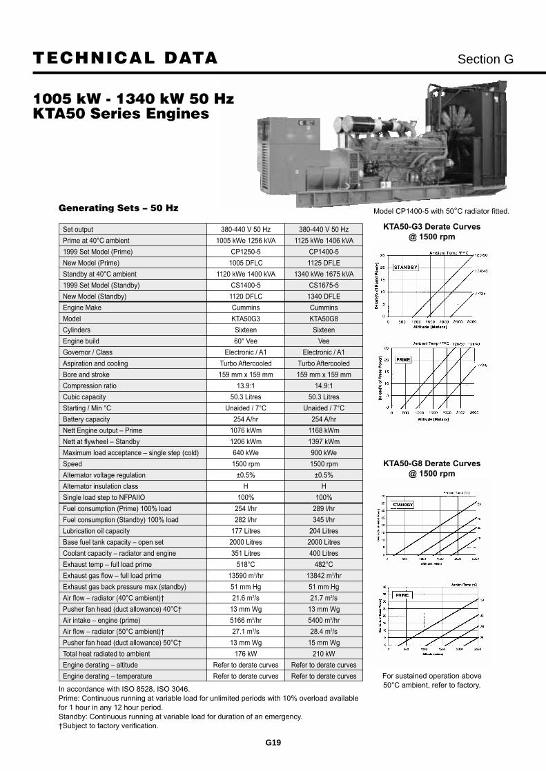
Section G
G19
Model CP1400-5 with 50°C radiator fitted.
1005 kW - 1340 kW 50 HzKTA50 Series Engines
TECHNICAL DATA
Generating Sets – 50 Hz
In accordance with ISO 8528, ISO 3046.Prime: Continuous running at variable load for unlimited periods with 10% overload availablefor 1 hour in any 12 hour period.Standby: Continuous running at variable load for duration of an emergency.Subject to factory verification.
Set output 380-440 V 50 Hz 380-440 V 50 Hz
Prime at 40°C ambient 1005 kWe 1256 kVA 1125 kWe 1406 kVA
1999 Set Model (Prime) CP1250-5 CP1400-5
New Model (Prime) 1005 DFLC 1125 DFLE
Standby at 40°C ambient 1120 kWe 1400 kVA 1340 kWe 1675 kVA
1999 Set Model (Standby) CS1400-5 CS1675-5
New Model (Standby) 1120 DFLC 1340 DFLE
Engine Make Cummins Cummins
Model KTA50G3 KTA50G8
Cylinders Sixteen Sixteen
Engine build 60° Vee Vee
Governor / Class Electronic / A1 Electronic / A1
Aspiration and cooling Turbo Aftercooled Turbo Aftercooled
Bore and stroke 159 mm x 159 mm 159 mm x 159 mm
Compression ratio 13.9:1 14.9:1
Cubic capacity 50.3 Litres 50.3 Litres
Starting / Min °C Unaided / 7°C Unaided / 7°C
Battery capacity 254 A/hr 254 A/hr
Nett Engine output Prime 1076 kWm 1168 kWm
Nett at flywheel Standby 1206 kWm 1397 kWm
Maximum load acceptance single step (cold) 640 kWe 900 kWe
Speed 1500 rpm 1500 rpm
Alternator voltage regulation ±0.5% ±0.5%
Alternator insulation class H H
Single load step to NFPAIIO 100% 100%
Fuel consumption (Prime) 100% load 254 l/hr 289 l/hr
Fuel consumption (Standby) 100% load 282 l/hr 345 l/hr
Lubrication oil capacity 177 Litres 204 Litres
Base fuel tank capacity open set 2000 Litres 2000 Litres
Coolant capacity radiator and engine 351 Litres 400 Litres
Exhaust temp full load prime 518°C 482°C
Exhaust gas flow full load prime 13590 m3/hr 13842 m3/hr
Exhaust gas back pressure max (standby) 51 mm Hg 51 mm Hg
Air flow radiator (40°C ambient) 21.6 m3/s 21.7 m3/s
Pusher fan head (duct allowance) 40°C 13 mm Wg 13 mm Wg
Air intake engine (prime) 5166 m3/hr 5400 m3/hr
Air flow radiator (50°C ambient) 27.1 m3/s 28.4 m3/s
Pusher fan head (duct allowance) 50°C 13 mm Wg 15 mm Wg
Total heat radiated to ambient 176 kW 210 kW
Engine derating altitude Refer to derate curves Refer to derate curves
Engine derating temperature Refer to derate curves Refer to derate curves
KTA50-G3 Derate Curves @ 1500 rpm
KTA50-G8 Derate Curves @ 1500 rpm
For sustained operation above50°C ambient, refer to factory.

Section G
G20
TECHNICAL DATA Dimensions & Weights 50 Hz
QSK60 Series
Floor mounted circuit breaker and load terminal cubicle (for use above 2000 amps)
Capacity Width Depth Heightamps mm mm mm1600 1000 1050 15002000 1000 1050 15002500 1000 1050 1500
*Weight given is with standard low voltage alternator.
Model Dim A Dim B Dim C Dry Weight*1350 DQKB 98.2 in 2494 mm 119.8 in 3043 mm 239.7 in 6090 mm 34260 lb 15540 kg1500 DQKC 98.2 in 2494 mm 119.8 in 3043 mm 239.7 in 6090 mm 34701 lb 15740 kg
Set weights are without sub-base tank.Dimensions and weights are for guidance only. Do not use for installation design. Ask for certified drawings on your specific application.
Specifications may change without notice.
A B
C

Section G
G21
TECHNICAL DATA
1350 kW - 1650 kW 50 HzQSK60 Series Engines
Standby Prime Standby Prime
Ratings kW (kVA) 1500 (1875) 1350 (1688) 1650 (2063) 1500 (1875)
Model 1500 DQKB 1350 DQKB 1650 DQKC 1500 DQKC
Engine Model QSK60-G3 QSK60-G3 QSK60-G3 QSK60-G3
Aspiration Turbocharged and Turbocharged and Turbocharged and Turbocharged andAftercooled Aftercooled Aftercooled Aftercooled
Gross Engine Power Output 1,615 kWm 1,453 kWm 1,790 kWm 1,615 kWm
BMEP 2,158 kPa 1,944 kPa 2,386 kPa 2,159 kPa
Bore 159 mm 159 mm 159 mm 159 mm
Stroke 190 mm 190 mm 190 mm 190 mm
Piston Speed 9.5 m/s 9.5 m/s 9.5 m/s 9.5 m/s
Compression Ratio 14.5:1 14.5:1 14.5:1 14.5:1
Lube Oil Capacity 280 Litres 280 Litres 280 Litres 280 Litres
Overspeed Limit 1,850 ± 50 rpm 1,850 ± 50 rpm 1,850 ± 50 rpm 1,850 ± 50 rpm
Regenerative Power 146 kW 146 kW 146 kW 146 kW
Fuel Consumption Load 1/4 1/2 3/4 Full 1/4 1/2 3/4 Full 1/4 1/2 3/4 Full 1/4 1/2 3/4 Full
Fuel Consumption L/hr 111 187 266 356 102.9 171 243 320 115 203 298 402 106 185 268 360
Maximum Fuel Flow 1,893 L/hr 1,893 L/hr 1,893 L/hr 1,893 L/hr
Maximum Inlet Restriction 120 mm Hg 120 mm Hg 120 mm Hg 120 mm Hg
Maximum Return Restriction 229 mm Hg 229 mm Hg 229 mm Hg 229 mm Hg
Maximum Fuel Inlet Temperature 70°C 70°C 70°C 70°C
Maximum Fuel Return Temperature 113°C 113°C 113°C 113°C
Fan Load 32 kW 32 kW 32 kW 32 kW
Coolant Capacity (with radiator) 492 Litres 492 Litres 492 Litres 492 Litres
Coolant Flow Rate (engine jacket) 1,438 L/Min 1,438 L/Min 1,438 L/Min 1,438 L/Min
Coolant Flow Rate (aftercooler) 426 L/Min 426 L/Min 426 L/Min 426 L/Min
Heat Rejection to Eng Jacket Coolant 27.3 MJ/Min 23.4 MJ/Min 33.0 MJ/Min 27.3 MJ/Min
Heat Rejection to Aftercooler Coolant 21.9 MJ/Min 19.0 MJ/Min 25.3 MJ/Min 21.9 MJ/Min
Heat Rejection to Fuel 2.1 MJ/Min 2.1 MJ/Min 2.1 MJ/Min 2.1 MJ/Min
Heat Radiated to Room 15.6 MJ/Min 13.9 MJ/Min 17.2 MJ/Min 15.6 MJ/Min
Max Coolant Friction Head (JW) 69 kPa 69 kPa 69 kPa 69 kPa
Max Coolant Friction Head (aftercooler) 35 kPa 35 kPa 35 kPa 35 kPa
Maximum Coolant Static Head 18.3 m 18.3 m 18.3 m 18.3 m
Heat Ex. Max Raw Water Flow (JW/AC) 1,363 L/Min 1,363 L/Min 1,363 L/Min 1,363 L/Min
Heat Ex. Max Raw Water Press (JW/AC/Fuel) 1,034 kPa 1,034 kPa 1,034 kPa 1,034 kPa
Heat Ex. Max Raw Water Flow (Fuel) 144 L/Min 144 L/Min 144 L/Min 144 L/Min
Max Top Tank Temp (engine jacket) 104°C 100°C 104°C 100°C
Max Inlet Temp (aftercooler) 61°C 61°C 66°C 66°C
Combustion Air 125 m3/min 113 m3/min 139 m3/min 125 m3/min
Maximum Air Cleaner Restriction 6.2 kPa 6.2 kPa 6.2 kPa 6.2 kPa
Alternator Cooling Air 246 m3/min 246 m3/min 246 m3/min 246 m3/min
Radiator Cooling Air 1,752 m3/min 1,752 m3/min 1,439 m3/min 1,439 m3/min
Minimum Air Opening to Room 8.4 m2 8.4 m2 8.4 m2 8.4 m2
Minimum Discharge Opening 5.7 m2 5.7 m2 5.7 m2 5.7 m2
Max Static Restriction 125 Pa 125 Pa 125 Pa 125 Pa
Gas Flow (Full Load) 303 m3/min 273 m3/min 334 m3/min 303 m3/min
Gas Temperature 505°C 493°C 515°C 505°C
Maximum Back Pressure** 6.8 kPa 6.8 kPa 6.8 kPa 6.8 kPa
Unit Dry Weight (with oil)** 15,875 kgs 15,875 kgs 15,875 kgs 15,875 kgs
Derating Factors Engine power available up to 6070 ft (1850 m) Engine power available up to 3280 ft (1000 m) at ambient temperatures up to 40°C (104°F). at ambient temperatures up to 40°C (104°F). Above 6070 ft (1850 m) derate at 3.5% per Above 3280 ft (1000 m) derate at 3.5% per 1000 ft (305 m), and 8% per 11°C (4% per 10°F) 1000 ft (305 m), and 8% per 11°C (4% per 10°F) above 40°C (104°F). above 40°C (104°F).
Generating Sets – 50 Hz
** Approximate only. Actual weight dependent upon options slected.


SELECTION CHART Section G
G23
60 Hz RatingsDiesel PoweredGenerating Sets32 kW - 2000 kW
Prime Rating Standby Model Cummins2000 Model 1999 Model 2000 Model 1999 Model Engine
kVA kW Prime Prime kVA kW Standby Standby Model40 32 32 DGGC CP40-6 43 35 35 DGGC CS40-6 B3.3G157 46 46 DGHC CP60-6 63 52 52 DGHC CS60-6 B3.3G244 36 36 DGBC CP40-6 50 40 40 DGBC CS50-6 4B3.9G60 48 48 DGCA CP60-6 64 51 51 DGCA CS60-6 4BT3.9G173 59 59 DGCB CP70-6 81 65 65 DGCB CS80-6 4BT3.9G283 66 66 DGCC CP80-6 89 72 72 DGCC CS90-6 4BTA3.9G295 76 76 DGDA CP100-6 106 85 85 DGDA CS100-6 6BT5.9G1119 95 95 DGDB CP125-6 131 105 105 DGDB CS125-6 6BT5.9G2153 122 122 DGEA CP160-6 167 133 133 DGEA CS170-6 6CT8.3G2210 168 168 DGFB CP200-6 228 182 182 DGFB CS200-6 6CTA8.3G2254 203 203 DFAB CP250-6 250 200 200 DFAB CS250-6 LTA10G2286 229 229 DFAC CP300-6 315 252 252 DFAC CS300-6 LTA10G1351 281 281 DFCB CP350-6 390 312 312 DFCB CS400-6 NTA855G2402 322 322 DFCC CP400-6 437 350 350 DFCC CS450-6 NTA855G3439 351 351 DFEB CP450-6 500 400 400 DFEB CS500-6 KTA19G2504 403 403 DFEC CP500-6 562 450 450 DFEC CS550-6 KTA19G3561 449 449 DFED CP550-6 626 501 501 DFED CS625-6 KTA19G4681 545 545 DFGB CP700-6 754 603 603 DFGB CS750-6 VTA28G5862 690 690 DFHA CP850-6 950 760 760 DFHA CS950-6 QST30G1920 736 736 DFHB CP900-6 1012 810 810 DFHB CS1000-6 QST30G2
1044 835 835 DFHC CP1000-6 1156 925 925 DFHC CS1100-6 QST30G31160 928 928 DFJD CP1100-6 1276 1020 1020 DFJD CS1250-6 KTA38G41400 1120 1120 DFLC CP1400-6 1587 1270 1270 DFLC CS1600-6 KTA50G31608 1286 1286 DFLE CP1600-6 1931 1545 1545 DFLE CS1900-6 KTA50G92000 1600 1600 DQKB CP2000-6 2188 1750 1750 DQKB CS2200-6 QSK60G62250 1800 1800 DQKC CP2250-6 2500 2000 2000 DQKC CS2500-6 QSK60G6
Rating Conditions:
All ratings at 40°C (104°F) ambient temperature with a 50°C (122°F) radiator.
Ratings: Prime (Unlimited Running Time), applicable for supplying power in lieu of commercially-purchased power.
Prime power is available at a variable load for an unlimited number of hours. A 10% overload capacity is available. Nominallyrated. All in accordance with ISO 8528, ISO 3046, AS 2789, DIN 6271 and BS 5514.
Standby: Applicable for supplying emergency power for the duration of normal power interruption. No sustained overloadcapability is available for this rating. Nominally rated. In accordance with ISO 3046, AS 2789, DIN 6271 and BS 5514.
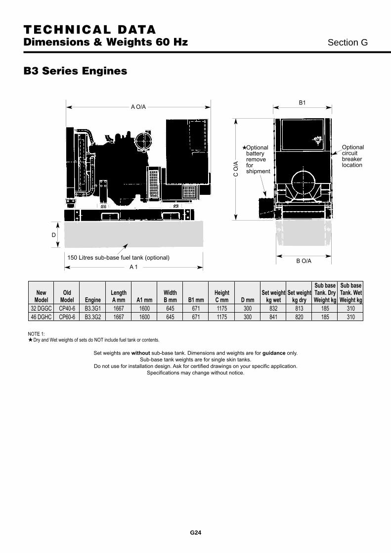
TECHNICAL DATA Dimensions & Weights 60 Hz Section G
G24
NOTE 1: Dry and Wet weights of sets do NOT include fuel tank or contents.
Set weights are without sub-base tank. Dimensions and weights are for guidance only.Sub-base tank weights are for single skin tanks.
Do not use for installation design. Ask for certified drawings on your specific application.Specifications may change without notice.
B3 Series Engines
D
150 Litres sub-base fuel tank (optional)
A 1B O/A
Optionalbatteryremoveforshipment
Optionalcircuitbreakerlocation
A O/A
C O
/A
B1
Sub base Sub baseNew Old Length Width Height Set weight Set weight Tank. Dry Tank. Wet
Model Model Engine A mm A1 mm B mm B1 mm C mm D mm kg wet kg dry Weight kg Weight kg32 DGGC CP40-6 B3.3G1 1667 1600 645 671 1175 300 832 813 185 31046 DGHC CP60-6 B3.3G2 1667 1600 645 671 1175 300 841 820 185 310

TECHNICAL DATA
G25
32 kW - 52 kW 60 HzB3 Series Engines
Section G
Set output 220-480 V 60 Hz 220-480 V 60 Hz
Prime at 40°C ambient 32 kWe 40 kVA 46 kWe 57 kVA
1999 Set Model (Prime) CP40-6 CP60-6
New Model (Prime) 32 DGGC 46 DGHC
Standby at 40°C ambient 35 kWe 43 kVA 52 kWe 63 kVA
1999 Set Model (Standby) CS40-6 CS60-6
New Model (Standby) 35 DGGC 52 DGHC
Engine Make Cummins Cummins
Model B3.3G1 B3.3G2
Cylinders Four Four
Engine build In-line In-line
Governor/Class Mechanical/G2 Mechanical/G2
Aspiration Natural aspiration Turbocharged
Bore and stroke 95 mm x 115 mm 95 mm x 115 mm
Compression ratio 8.2 17
Cubic capacity 3.26 Litres 3.26 Litres
Starting/Min °C Unaided/4°C Unaided/4°C
Battery capacity 126 A/hr 126 A/hr
Nett Engine output @ flywheel @ Prime 36.6 kWm 52.7 kWm
Nett at Engine output @ flywheel @ Standby 40.3 kWm 59.3 kWm
Maximum load acceptance @ single step 100% 100%
Speed 1800 rpm 1800 rpm
Alternator voltage regulation ±1.5% ±1.5%
Alternator insulation class H H
Single load step to NFPA110 100% 100%
Fuel consumption (Prime) 100% load 8.7 l/hr 13.3 l/hr
Fuel consumption (Standby) 100% load 9.8 l/hr 14.8 l/hr
Lubrication oil capacity 8 Litres 8 Litres
Base fuel tank capacity open set 150 Litres 150 Litres
Coolant capacity radiator and engine 11.5 Litres 14 Litres
Exhaust temp @ full load standby 460°C 510°C
Exhaust gas flow @ full load standby 424 m3/hr 608 m3/hr
Exhaust gas back pressure max 76 mm Hg 76 mm Hg
Air flow radiator @ 0mm back pressure 8430 m3/hr 5866 m3/hr
Air intake engine 144 m3/hr 231 m3/hr
Minimum air opening to room* 0.48 sq m 0.63 sq m
Minimum discharge opening* 0.36 sq m 0.47 sq m
Pusher fan head (duct allowance) 12 mm Wg 12 mm Wg
Total heat radiated to ambient 13.1 kW 21.1 kW
Engine derating for altitude 0.7% per 100 m 0.9% per 100 mabove 1000 m above 1000 m
Engine derating for temperature 1% per 10°C 4.5% per 10°Cabove 40°C above 40°C
Generating Sets – 60 Hz
In accordance with ISO 8528, ISO 3046.Prime: Continuous running at variable load for unlimited periods with 10% overload available for 1 hour in any 12 hour period.Standby: Continuous running at variable load for duration of an emergency.Prime and standby ratings are outputs at 40°C (104°F) ambient temperature and 1000m altitude reference.*Subject to 6mm Wg each, inlet and outlet restriction.

TECHNICAL DATA Dimensions & Weights 60 Hz Section G
G26
NOTE 1: Battery/tray extends out 260 mm from side when fitted. Dry and Wet weights of sets do NOT include fuel tank or contents.
B1
B O/A
A O/A
D
C O
/A
Optionalcircuitbreaker orcableentrancebox can befitted eitherside orboth
Optional sub-base fuel tank Battery removable
for shipment A 1
4B Series Engines
Weights are without sub-base tank. Dimensions and weights are for guidance only. Do not use for installation design. Ask for certified drawings on your specific application. Specifications may change without notice.
NOTE 1: Battery tray extends out 260 mm from side – when fitted. Dry and Wet weights of sets do NOT include fuel tank or contents.
B1
A O/A
C O
/A
Optionalcircuitbreaker orcableentrancebox can befitted eitherside
Optional sub-base fuel tankBattery removablefor shipment
D
A 1
B O/A
Sub base Sub baseNew Old Length Width Height Set weight Set weight Tank. Dry Tank. Wet
Model Model Engine A mm A1 mm B1 mm B mm C mm D mm kg wet kg dry Weight kg Weight kg36 DGBC CP40-6 4B3.9G 1720 1675 840 675 1345 200 800 772 150 31048 DGCA CP60-6 4BT3.9G1 1810 1675 840 675 1245 200 870 842 150 31059 DGCB CP70-6 4BT3.9G2 1810 1675 840 675 1245 200 920 892 150 31066 DGCC CP80-6 4BTA3.9G2 1847 1675 840 675 1377 200 975 938 150 310
6B Series Engines
Sub base Sub baseNew Old Length Width Height Set weight Set weight Tank. Dry Tank. Wet
Model Model Engine A mm A1 mm B1 mm B mm C mm D mm kg wet kg dry Weight kg Weight kg76 DGDA CP100-6 6BT5.9G1 2087 1675 840 675 1337 200 1100 1060 150 31095 DGDB CP125-6 6BT5.9G2 2162 1675 840 675 1337 200 1175 1131 150 310

TECHNICAL DATA
G27
36 kW - 72 kW 60 Hz4B Series Engines
Section G
Set output 220-480 V 60 Hz 220-480 V 60 Hz 220-480 V 60 Hz 220-480 V 60 Hz
Prime at 40°C ambient 36 kWe 44 kVA 48 kWe 60 kVA 59 kWe 73 kVA 66 kWe 83 kVA
1999 Set Model (Prime) CP40-6 CP60-6 CP70-6 CP80-6
New Model (Prime) 36 DGBC 48 DGCA 59 DGCB 66 DGCC
Standby at 40°C ambient 40 kWe 50 kVA 51 kWe 64 kVA 65 kWe 81 kVA 72 kWe 89 kVA
1999 Set Model (Standby) CS50-6 CS60-6 CS80-6 CS90-6
New Model (Standby) 40 DGBC 51 DGCA 65 DGCB 72 DGCC
Engine Make Cummins Cummins Cummins Cummins
Model 4B3.9G 4BT3.9G1 4BT3.9G2 4BTA3.9G2
Cylinders Four Four Four Four
Engine build In-line In-line In-line In-line
Governor/Class Mechanical Mechanical Mechanical Mechanical
Aspiration and cooling Natural aspiration Turbocharged Turbocharged Turbocharged
Bore and stroke 102 mm x 120 mm 102 mm x 120 mm 102 mm x 120 mm 102 mm x 120 mm
Compression ratio 17.3:1 16.5:1 16.5:1 16.5:1
Cubic capacity 3.92 Litres 3.92 Litres 3.92 Litres 3.92 Litres
Starting/Min °C Unaided/12°C Unaided/12°C Unaided/12°C Unaided/12°C
Battery capacity 165 A/hr 165 A/hr 165 A/hr 165 A/hr
Nett Engine output Prime 40 kWm 54 kWm 65 kWm 73 kWm
Nett at flywheel Standby 46 kWm 60 kWm 72 kWm 80 kWm
Speed 1800 rpm 1800 rpm 1800 rpm 1800 rpm
Alternator voltage regulation ±1.0% ±1.0% ±1.0% ±1.0%
Alternator insulation class H H H H
Single load step to NFPAII0 para 5.13.2.6 100% 100% 100% 100%
Fuel consumption (Prime) 100% load 12.8 l/hr 14.99 l/hr 17.6 l/hr 18.0 l/hr
Fuel consumption (Standby) 100% load 14.5 l/hr 16.43 l/hr 19.5 l/hr 20.0 l/hr
Lubrication oil capacity 9.5 Litres 9.5 Litres 9.5 Litres 9.5 Litres
Base fuel tank capacity open set 197 Litres 197 Litres 197 Litres 197 Litres
Coolant capacity radiator and engine 21 Litres* 21 Litres* 21 Litres* 21 Litres*
Exhaust temp full load prime 604°C 463°C 510°C 461°C
Exhaust gas flow full load prime 550 m3/hr 630 m3/hr 713 m3/hr 810 m3/hr
Exhaust gas back pressure max 76 mm Hg 76 mm Hg 76 mm Hg 76 mm Hg
Air flow radiator 2.9 m3/s 2.9 m3/s 2.9 m3/s 2.27 m3/s
Air intake engine 180 m3/hr 237 m3/hr 252 m3/hr 349 m3/hr
Minimum air opening to room 0.7 sq m 0.7 sq m 0.7 sq m 0.7 sq m
Minimum discharge opening 0.5 sq m 0.5 sq m 0.5 sq m 0.5 sq m
Pusher fan head (duct allowance) 10 mm Wg* 10 mm Wg* 10 mm Wg* 10 mm Wg*
Total heat radiated to ambient 11.4 kW 15 kW 17 kW 18 kW
Engine derating altitude 3% per 300 m 4% per 300 m 4% per 300 m 4% per 300 mabove 150 m above 1525 m above 1220 m above 1220 m
Engine derating temperature 2% per 11°C 2% per 11°C 2% per 11°C 2% per 11°Cabove 40°C above 40°C above 40°C above 40°C
Generating Sets – 60 Hz
In accordance with ISO 8528, BS5514.Prime: Continuous running at variable load for unlimited periods with 10% overload available for 1 hour in any 12 hour period.Standby: Continuous running at variable load for duration of an emergency.Prime and standby ratings are outputs at 40°C (104°F) ambient temperature reference.*Subject to factory verification.
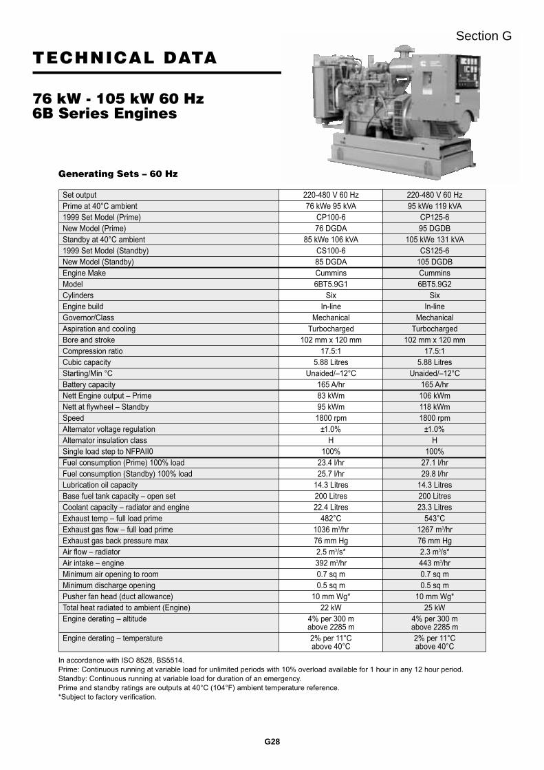
TECHNICAL DATA
G28
76 kW - 105 kW 60 Hz6B Series Engines
Section G
Set output 220-480 V 60 Hz 220-480 V 60 HzPrime at 40°C ambient 76 kWe 95 kVA 95 kWe 119 kVA1999 Set Model (Prime) CP100-6 CP125-6New Model (Prime) 76 DGDA 95 DGDBStandby at 40°C ambient 85 kWe 106 kVA 105 kWe 131 kVA1999 Set Model (Standby) CS100-6 CS125-6New Model (Standby) 85 DGDA 105 DGDBEngine Make Cummins CumminsModel 6BT5.9G1 6BT5.9G2Cylinders Six SixEngine build In-line In-lineGovernor/Class Mechanical MechanicalAspiration and cooling Turbocharged TurbochargedBore and stroke 102 mm x 120 mm 102 mm x 120 mmCompression ratio 17.5:1 17.5:1Cubic capacity 5.88 Litres 5.88 LitresStarting/Min °C Unaided/12°C Unaided/12°CBattery capacity 165 A/hr 165 A/hrNett Engine output Prime 83 kWm 106 kWmNett at flywheel Standby 95 kWm 118 kWmSpeed 1800 rpm 1800 rpmAlternator voltage regulation ±1.0% ±1.0%Alternator insulation class H HSingle load step to NFPAII0 100% 100%Fuel consumption (Prime) 100% load 23.4 l/hr 27.1 l/hrFuel consumption (Standby) 100% load 25.7 l/hr 29.8 l/hrLubrication oil capacity 14.3 Litres 14.3 LitresBase fuel tank capacity open set 200 Litres 200 LitresCoolant capacity radiator and engine 22.4 Litres 23.3 LitresExhaust temp full load prime 482°C 543°CExhaust gas flow full load prime 1036 m3/hr 1267 m3/hrExhaust gas back pressure max 76 mm Hg 76 mm HgAir flow radiator 2.5 m3/s* 2.3 m3/s*Air intake engine 392 m3/hr 443 m3/hrMinimum air opening to room 0.7 sq m 0.7 sq mMinimum discharge opening 0.5 sq m 0.5 sq mPusher fan head (duct allowance) 10 mm Wg* 10 mm Wg*Total heat radiated to ambient (Engine) 22 kW 25 kWEngine derating altitude 4% per 300 m 4% per 300 m
above 2285 m above 2285 mEngine derating temperature 2% per 11°C 2% per 11°C
above 40°C above 40°C
Generating Sets – 60 Hz
In accordance with ISO 8528, BS5514.Prime: Continuous running at variable load for unlimited periods with 10% overload available for 1 hour in any 12 hour period.Standby: Continuous running at variable load for duration of an emergency.Prime and standby ratings are outputs at 40°C (104°F) ambient temperature reference.*Subject to factory verification.

TECHNICAL DATA Dimensions & Weights 60 Hz Section G
G29
NOTE 1: Battery tray extends out 260 mm from side – when fitted. Dry and Wet weights of sets do NOT include fuel tank or contents.
B1
B O/A A O/AC
O/A
Optionalcircuitbreaker orcableentrancebox can befitted eitherside
Batteryremovableforshipment
Optional sub-base fuel tank
D
A 1
6C Series Engines
LTA10 Series Engines
Set weights are without sub-base tank.Dimensions and weights are for guidance only. Do not use for installation design. Ask for certified drawings on your specific application.
Specifications may change without notice.
B
B1A1
A O/A
C O
/A
D
Load terminalsand optionalcircuit breakereither side.
Optional sub-base fuel tank.
Batteryremoved forshipping.Extends 20cm
Sub base Sub baseNew Old Length Width Height Set weight Set weight Tank. Dry Tank. Wet
Model Model Engine A mm A1 mm B1 mm B mm C mm D mm kg wet kg dry Weight kg Weight kg122 DGEA CP150-6 6CT8.3G2 2332 2200 840 831 1412 250 1550 1498 210 490168 DGFB CP200-6 6CTA8.3G2 2389 2200 840 831 1412 250 1760 1704 210 490
New Old Dimensions and Weights (mm/kg) Set Weight Set Weight Tank (dry) Tank (wet)Model Engine Model A A1 B B1 C D kg Dry kg Wet Weight kg Weight kg
203 DFAB LTA10G2 CP250-6 2980 3338 1048 1050 1644 300 2230 2300 445 1085229 DFAC LTA10G1 CP300-6 2980 3338 1048 1050 1644 300 2332 2380 445 1085

TECHNICAL DATA
G30
122 kW - 182 kW 60 Hz6C Series Engines
Section G
Set output 220-480 V 60 Hz 220-480 V 60 HzPrime at 40°C ambient 122 kWe 153 kVA 168 kWe 210 kVA1999 Set Model (Prime) CP150-6 CP200-6New Model (Prime) 122 DGEA 168 DGFBStandby at 40°C ambient 133 kWe 167 kVA 182 kWe 228 kVA1999 Set Model (Standby) CS170-6 CS200-6New Model (Standby) 133 DGEA 182 DGFBEngine Make Cummins CumminsModel 6CT8.3G2 6CTA8.3G2Cylinders Six SixEngine build In-line In-lineGovernor/Class Mechanical MechanicalAspiration and cooling Turbocharged Turbo AfterchargedBore and stroke 114 mm x 135 mm 114 mm x 135 mmCompression ratio 16.8:1 16.5:1Cubic capacity 8.3 Litres 8.3 LitresStarting/Min °C Unaided/12°C Unaided/12°CBattery capacity 165 A/hr 165 A/hrNett Engine output Prime 132 kWm 180 kWmNett at flywheel Standby 146 kWm 199 kWmSpeed 1800 rpm 1800 rpmAlternator voltage regulation ±1.0% ±1.0%Alternator insulation class H HSingle load step to NFPAII0 100% 100%Fuel consumption (Prime) 100% load 37 l/hr 46 l/hrFuel consumption (Standby) 100% load 41 l/hr 51 l/hrLubrication oil capacity 23.8 Litres 23.8 LitresBase fuel tank capacity open set 330 Litres 330 LitresCoolant capacity radiator and engine 26 Litres 28 LitresExhaust temp full load prime 511°C 591°CExhaust gas flow full load prime 1872 m3/hr 2343 m3/hrExhaust gas back pressure max 76 mm Hg 76 mm HgAir flow radiator* 4.4 m3/s 3.9 m3/sAir intake engine 752 m3/hr 781 m3/hrMinimum air opening to room 0.9 sq m 0.9 sq mMinimum discharge opening 0.6 sq m 0.6 sq mPusher fan head (duct allowance)* 13 mm Wg* 13 mm Wg*Total heat radiated to ambient (Engine) 36 kW 40 kWEngine derating altitude 4% per 300 m 4% per 300 m
above 1525 m above 1525 mEngine derating temperature 2% per 11°C 2% per 5°C
above 40°C above 40°C
Generating Sets – 60 Hz
In accordance with ISO 8528, BS5514.Prime: Continuous running at variable load for unlimited periods with 10% overload available for 1 hour in any 12 hour period.Standby: Continuous running at variable load for duration of an emergency.Prime and standby ratings are outputs at 40°C (104°F) ambient temperature reference.*Subject to factory verification.

TECHNICAL DATASection G
G31
203 kW - 252 kW 60 HzLTA10 Series Engines
Set output 220-480 V 60 Hz 220-480 V 60 HzPrime at 40°C ambient 203 kWe 254 kVA 229 kWe 286 kVA1999 Set Model (Prime) CP250-6 CP300-6New Model (Prime) 203 DFAB 229 DFACStandby at 40°C ambient 200 kWe 250 kVA 252 kWe 315 kVA1999 Set Model (Standby) CS250-6 CS300-6New Model (Standby) 200 DFAB 252 DFACEngine Make Cummins CumminsModel LTA10G2 LTA10G1Cylinders Six SixEngine build In-line In-lineGovernor/Class Electronic/A1 Electronic/A1Aspiration and cooling Turbo Aftercooled Turbo AftercooledBore and stroke 125 mm x 136 mm 125 mm x 136 mmCompression ratio 16.0:1 16.0:1Cubic capacity 10 Litres 10 LitresStarting/Min °C Unaided/1°C Unaided/1°CBattery capacity 2 x 127 A/hr 2 x 127 A/hrNett Engine output Prime 220 kWm 246 kWmNett at flywheel Standby 246 kWm 272 kWmSpeed 1800 rpm 1800 rpmAlternator voltage regulation ±1.0% ±1.0%Alternator insulation class H HSingle load step to NFPAII0 100% 100%Fuel consumption (Prime) 100% load 56.4 l/hr 59 l/hrFuel consumption (Standby) 100% load 63.2 l/hr 64.7 l/hrLubrication oil capacity 36 Litres 36 LitresBase fuel tank capacity open set 675 Litres 675 LitresCoolant capacity radiator and engine 61.8 Litres 61.8 LitresExhaust temp full load prime 485°C 504°CExhaust gas flow full load prime 2812 m3/hr 2794 m3/hrExhaust gas back pressure max 76 mm Hg 76 mm HgAir intake engine 1069 m3/hr 1037 m3/hrAir flow radiator (50°C) 6.5 m3/s 6.5 m3/sPusher fan head (duct allowance) 50°C 13 mm Wg 13 mm WgTotal heat radiated to ambient 50 kW 55 kWEngine derating altitude 4% per 300 m 4% per 300 m
above 1220 m above 1525 mEngine derating temperature 2% per 11°C 2% per 11°C
above 40°C above 40°C
Generating Sets – 60 Hz
In accordance with ISO 8528, BS5514.Prime: Continuous running at variable load for unlimited periods with 10% overload available for 1 hour in any 12 hour period.Standby: Continuous running at variable load for duration of an emergency.

TECHNICAL DATA Dimensions & Weights 60 Hz Section G
G32
B O/A B1A1
A O/A
D
SUB-BASE FUEL TANK OPTION
C O
/A
Optionalentrance boxor circuitbreaker eitherside.
Battery protrudes190mm
NT855 Series Engines
K19 Series Engines
Set weights are without sub-base tank.Dimensions and weights are for guidance only. Do not use for installation design. Ask for certified drawings on your specific application.
Specifications may change without notice.
SUB-BASE FUEL TANK OPTION
A O/A
C O
/A
B
Battery protrudes 100mmRemoved for shipping
B1A1
D
Optionalentrance boxor circuitbreaker eitherside.
New Old Dimensions and Weights (mm/kg) Set Weight Set Weight Tank Weight Tank WeightModel Engine Model A A1 B B1 C D kg Dry kg Wet kg (dry) kg (wet)
281 DFCB NTA855G2 CP350-6 3286 3338 990 1048 1117 300 3178 3275 445 1085322 DFCC NTA855G3 CP400-6 3304 3338 990 1048 1117 300 3293 3390 445 1085
New Old Dimensions and Weights (mm/kg) Set Weight Set Weight Tank Weight Tank WeightModel Engine Model A A1 B B1 C D kg Dry kg Wet kg (dry) kg (wet)
351 DFEB KTA19G2 CP450-6 3490 3875 1266 1350 1830 300 4136 4270 580 1580403 DFEC KTA19G3 CP500-6 3490 3875 1266 1350 1830 300 4276 4410 580 1580449 DFED KTA19G4 CP550-6 3490 3875 1266 1350 1830 300 4276 4410 580 1580

TECHNICAL DATA
G33
281 kW - 350 kW 60 HzNT855 Series Engines
Section G
Set output 220-480 V 60 Hz 220-480 V 60 HzPrime at 40°C ambient 281 kWe 351 kVA 322 kWe 402 kVA1999 Set Model (Prime) CP350-6 CP400-6New Model (Prime) 281 DFCB 322 DFCCStandby at 40°C ambient 312 kWe 390 kVA 350 kWe 437 kVA1999 Set Model (Standby) CS400-6 CS450-6New Model (Standby) 312 DFCB 350 DFCCEngine Make Cummins CumminsModel NTA855G2 NTA855G3Cylinders Six SixEngine build In-line In-lineGovernor/Class Electronic/A1 Electronic/A1Aspiration and cooling Turbo Aftercooled Turbo AftercooledBore and stroke 140 mm x 152 mm 140 mm x 152 mmCompression ratio 14.0:1 14.0:1Cubic capacity 14 Litres 14 LitresStarting/Min °C Unaided/7°C Unaided/7°CBattery capacity 127 A/hr 127 A/hrNett Engine output Prime 299 kWm 344 kWmNett at flywheel Standby 333 kWm 385 kWmSpeed 1800 rpm 1800 rpmAlternator voltage regulation ±1.0% ±1.0%Alternator insulation class H HSingle load step to NFPAII0 100% 100%Fuel consumption (Prime) 100% load 79 l/hr 87 l/hrFuel consumption (Standby) 100% load 89 l/hr 96 l/hrLubrication oil capacity 38.6 Litres 38.6 LitresBase fuel tank capacity open set 800 Litres 800 LitresCoolant capacity radiator and engine 79.8 Litres 84.8 LitresExhaust temp full load prime 466°C 521°CExhaust gas flow full load prime 4136 m3/hr 4734 m3/hrExhaust gas back pressure max 76 mm Hg 76 mm HgAir intake engine 1613 m3/hr 1717 m3/hrAir flow radiator (50°C) 9.7 m3/s 9.2 m3/sPusher fan head (duct allowance) 50°C 13 mm Wg 13 mm WgTotal heat radiated to ambient 72 kW 76 kWEngine derating altitude 4% per 300 m 4% per 300 m
above 1525 m above 1525 mEngine derating temperature 2% per 11°C 2% per 11°C
above 40°C above 40°C
Generating Sets – 60 Hz
In accordance with ISO 8528, BS5514.Prime: Continuous running at variable load for unlimited periods with 10% overload available for 1 hour in any 12 hour period.Standby: Continuous running at variable load for duration of an emergency.

TECHNICAL DATA
G34
351 kW - 453 kW 60 HzK19 Series Engines
Section G
Generating Sets – 60 Hz
In accordance with ISO 8528, BS5514.Prime: Continuous running at variable load for unlimited periods with 10% overload available for 1 hour in any 12 hour period.Standby: Continuous running at variable load for duration of an emergency.*Subject to factory verification.
Set output 220-480 V 60 Hz 220-480 V 60 Hz 220-480 V 60 HzPrime at 40°C ambient 351 kWe 439 kVA 403 kWe 504 kVA 449 kWe 561 kVA1999 Set Model (Prime) CP450-6 CP500-6 CP550-6New Model (Prime) 351 DFEB 403 DFEC 449 DFEDStandby at 40°C ambient 400 kWe 500 kVA 450 kWe 562 kVA 501 kWe 626 kVA1999 Set Model (Standby) CS500-6 CS550-6 CS625-6New Model (Standby) 400 DFEB 450 DFEC 501 DFEDEngine Make Cummins Cummins CumminsModel KTA19G2 KTA19G3 KTA19G4Cylinders Six Six SixEngine build In-line In-line In-lineGovernor/Class Electronic/A1 Electronic/A1 Electronic/A1Aspiration and cooling Turbo Aftercooled Turbo Aftercooled Turbo AftercooledBore and stroke 159 mm x 159 mm 159 mm x 159 mm 159 mm x 159 mmCompression ratio 13.9:1 13.9:1 13.9:1Cubic capacity 18.9 Litres 18.9 Litres 18.9 LitresStarting/Min °C Unaided/7°C Unaided/7°C Unaided/0°CBattery capacity 190 A/hr 190 A/hr 190 A/hrNett Engine output Prime 373 kWm 429 kWm 473 kWmNett at flywheel Standby 429 kWm 477 kWm 529 kWmSpeed 1800 rpm 1800 rpm 1800 rpmAlternator voltage regulation ±1.0% ±1.0% ±1.0%Alternator insulation class H H HSingle load step to NFPAII0 100% 100% 100%Fuel consumption (Prime) 100% load 98 l/hr 111 l/hr 120 l/hrFuel consumption (Standby) 100% load 113 l/hr 122 l/hr 133 l/hrLubrication oil capacity 50 Litres 50 Litres 50 LitresBase fuel tank capacity open set 1200 Litres 1200 Litres 1200 LitresCoolant capacity radiator and engine 105 Litres 105 Litres 105 LitresExhaust temp full load prime 493°C 471°C 481°CExhaust gas flow full load prime 5554 m3/hr 5684 m3/hr 6242 m3/hrExhaust gas back pressure max 76 mm Hg 76 mm Hg 76 mm HgAir intake engine 2092 m3/hr 2199 m3/hr 2473 m3/hrAir flow radiator (50°C)* 11.3 m3/s 14.8 m3/s 14.8 m3/sPusher fan head (duct allowance) 50°C* 13 mm Wg 13 mm Wg 13 mm WgTotal heat radiated to ambient 85 kW 95 kW 99 kWEngine derating altitude 4% per 300 m 4% per 300 m 4% per 300 m
above 1525 m above 1525 m above 1525 mEngine derating temperature 2% per 11°C 2% per 11°C 2% per 11°C
above 40°C above 40°C above 40°C

TECHNICAL DATA Dimensions & Weights 60 Hz Section G
G35
A
A1
D
B1
B
C
Optional base tank.
Optional circuitbreaker or cableentrance box canbe fitted eitherside.
Battery protrudesapprox 120mmRemovable for
shipment
VTA28 Series Engines
Set weights are without sub-base tank.Dimensions and weights are for guidance only. Do not use for installation design. Ask for certified drawings on your specific application. Specifications may change without notice.
New Old Dimensions and Weights (mm/kg) Set Weight Set Weight Tank Weight Tank WeightModel Engine Model A A1 B1 B C D kg Dry kg Wet kg (dry) kg (wet)
545 DFGB VTA28G5 CP700-6 4047 4092 1350 1423 1987 300 5730 6040 610 1670
B
A1 B1
A
C
D
Optionalcableentrance boxand optionalcircuitbreaker can bepositionedeither side.
Optional sub-basefuel tank.
Battery extends 120mm.(Removed for shipment)
804
QST30 Series Engines
New Old Dimensions and Weights (mm/kg) Set Weight Set Weight Tank Weight Tank WeightModel Engine Model A A1 B B1 C D kg Dry kg Wet kg (dry) kg (wet)
690 DFHA QST30G1 CP850-6 4297 4460 1442 1640 2092 300 6702 7000 850 2210736 DFHB QST30G2 CP900-6 4297 4460 1442 1640 2092 300 6852 7150 850 2210835 DFHC QST30G3 CP1000-6 4391 4460 1442 1640 2092 300 7152 7450 850 2210

TECHNICAL DATA
G36
545 kW - 603 kW 60 HzVTA28 Series Engines
Section G
Generating Sets – 60 Hz
In accordance with ISO 8528, BS5514.Prime: Continuous running at variable load for unlimited periods with 10% overload available for 1 hour in any 12 hour period.Standby: Continuous running at variable load for duration of an emergency.*Subject to factory verification.
Set output 220-480 V 60 HzPrime at 40°C ambient 545 kWe 681 kVA1999 Set Model (Prime) CP700-6New Model (Prime) 545 DFGBStandby at 40°C ambient 603 kWe 754 kVA1999 Set Model (Standby) CS750-6New Model (Standby) 603 DFGBEngine Make CumminsModel VTA28G5Cylinders TwelveEngine build VeeGovernor / Class Electronic / A1Aspiration and cooling Turbo AftercooledBore and stroke 140 mm x 152 mmCompression ratio 13.0:1Cubic capacity 28 LitresStarting / Min °C Unaided / 4°CBattery capacity 254 A/hrNett Engine output Prime 576 kWmNett at flywheel Standby 639 kWmSpeed 1800 rpmAlternator voltage regulation ±1.0%Alternator insulation class HSingle load step to NFPAIIO para.5.13.2.6 100%Fuel consumption (Prime) 100% load 154 l/hrFuel consumption (Standby) 100% load 173 l/hrLubrication oil capacity 83 Litres Base fuel tank capacity open set 1325 LitresCoolant capacity radiator and engine 207 LitresExhaust temp full load prime 474°CExhaust gas flow full load prime 7877 m3/hrExhaust gas back pressure max 76 mm HgAir intake engine 3510 m3/hrAir flow radiator (50°C)* 19.4 m3/sPusher fan head (duct allowance) 50°C* 13 mm WgTotal heat radiated to ambient 133 kWEngine derating altitude 4% per 300 m
above 1220 mEngine derating temperature 2% per 11°C
above 40°C

G37
TECHNICAL DATA
690 kW - 925 kW 60 HzQST30 Series Engines
Section G
Set output 220-480 V 60 Hz 220-480 V 60 Hz 220-480 V 60 HzPrime at 40°C ambient 690 kWe 862 kVA 736 kWe 920 kVA 835 kWe 1044 kVA1999 Set Model (Prime) CP850-6 CP900-6 CP1000-6New Model (Prime) 690 DFHA 736 DFHB 835 DFHCStandby at 40°C ambient 760 kWe 950 kVA 810 kWe 1012 kVA 925 kWe 1156 kVA1999 Set Model (Standby) CS950-6 CS1000-6 CS1100-6New Model (Standby) 760 DFHA 810 DFHB 925 DFHCEngine Make Cummins Cummins CumminsModel QST30G1 QST30G2 QST30G3Cylinders Twelve Twelve TwelveEngine build Vee Vee VeeGovernor/Class Electronic/A1 Electronic/A1 Electronic/A1Aspiration and cooling Turbo Aftercooled Turbo Aftercooled Turbo AftercooledBore and stroke 140 mm x 165 mm 140 mm x 165 mm 140 mm x 165 mmCompression ratio 14:1 14:1 14:1Cubic capacity 30.48 Litres 30.48 Litres 30.48 LitresStarting/Min °C Unaided/1°C Unaided/1°C Unaided/7°CBattery capacity 254 A/hr 254 A/hr 254 A/hrNett Engine output Prime 718 kWm 759 kWm 910 kWmNett Engine output Standby 796 kWm 844 kWm 1007 kWmSpeed 1800 rpm 1800 rpm 1800 rpmAlternator voltage regulation ±0.5% ±0.5% ±0.5%Alternator insulation class H H HSingle load step to NFPAII0 100% 100% 100%Fuel consumption (Prime) 100% load 186 l/hr 197 l/hr 207 l/hrFuel consumption (Standby) 100% load 207 l/hr 219 l/hr 228 l/hrLubrication oil capacity 154 Litres 154 Litres 154 LitresBase fuel tank capacity open set 1700 Litres 1700 Litres 1700 LitresCoolant capacity radiator and engine 168 Litres 168 Litres 168 LitresExhaust temp full load prime 455°C 467°C 464°CExhaust gas flow full load prime 9432 m3/hr 10058 m3/hr 10800 m3/hrExhaust gas back pressure max 76 mm Hg 76 mm Hg 76 mm HgAir intake engine 3679 m3/hr 3859 m3/hr 4284 m3/hrAir flow 40°C ambient* 19.1 m3/s 19.1 m3/s TBAAir flow radiator (50°C ambient)* 21.9 m3/s 21.9 m3/s 21.9 m3/sPusher fan head (duct allowance) 50°C* 13 mm Wg 13 mm Wg 13 mm WgTotal heat radiated to ambient (prime) 153 kW 166 kW 152 kWEngine derating altitude 4% per 300 m 4% per 300 m 4% per 300 m
above 1524 m above 1524 m above 1000 mEngine derating temperature 2% per 11°C above 40°C 2% per 11°C above 40°C 2% per 11°C above 40°C
(52°C below 305 m) (52°C below 305 m)
Generating Sets – 60 Hz
In accordance with ISO 8528, BS5514.Prime: Continuous running at variable load for unlimited periods with 10% overload available for 1 hour in any 12 hour period.Standby: Continuous running at variable load for duration of an emergency.Prime and standby ratings are outputs at 40°C (104°F) ambient temperature.*Subject to factory verification.

G38
KTA38 Series Engines
Set weights are without sub-base tank.Dimensions and weights are for guidance only. Do not use for installation design. Ask for certified drawings on your specific application. Specifications may change without notice.
B A O/A
A1 B1
SUB-BASE FUEL TANK OPTION
D
C O
/A
Floor mounted circuit breaker and load terminal cubicle (for use above 1250 amps)
Capacity Width Depth Heightamps mm mm mm1600 1000 1050 15002000 1000 1050 15002500 1000 1050 15003200 1000 1050 1500
New Old Dimensions and Weights (mm/kg) Set Weight Set Weight Tank Weight Tank WeightModel Engine Model A A1 B B1 C D kg Dry kg Wet kg (dry) kg (wet)
928 DFJD KTA38G4 CP1100-6 4470 4600 1785 1640 2229 300 8527 8600 850 2210
TECHNICAL DATA Dimensions & Weights 60 Hz Section G

G39
TECHNICAL DATA
928 kW - 1020 kW 60 HzKTA38 Series Engines
Section G
In accordance with ISO 8528, BS5514.Prime: Continuous running at variable load for unlimited periods with 10% overload available for 1 hour in any 12 hour period.Standby: Continuous running at variable load for duration of an emergency.*Subject to factory verification.
Set output 220-480 V 60 HzPrime at 40°C ambient 928 kWe 1160 kVA1999 Set Model (Prime) CP1100-6New Model (Prime) 928 DFJDStandby at 40°C ambient 1020 kWe 1276 kVA1999 Set Model (Standby) CS1250-6New Model (Standby) 1020 DFJDEngine Make CumminsModel KTA38G4Cylinders TwelveEngine build VeeGovernor / Class Electronic / A1Aspiration and cooling Turbo AftercooledBore and stroke 159 mm x 159 mmCompression ratio 13.9:1Cubic capacity 37.8 LitresStarting / Min °C Unaided / 7°CBattery capacity 254 A/hrNett Engine output Prime 973 kWmNett at flywheel Standby 1078 kWmSpeed 1800 rpmAlternator voltage regulation ±0.5%Alternator insulation class HSingle load step to NFPAII0 para 5.13.2.6 100%Fuel consumption (Prime) 100% load 245 l/hrFuel consumption (Standby) 100% load 271 l/hrLubrication oil capacity 135 LitresBase fuel tank capacity open set 1700 LitresCoolant capacity radiator and engine 307 LitresExhaust temp full load prime 499°CExhaust gas flow full load prime 13107 m3/hrExhaust gas back pressure max 76 mm HgAir intake engine (Prime) 4892 m3/hrAir flow radiator (50°C ambient)* 28.5 m3/sPusher fan head (duct allowance) 50°C* 13 mm WgTotal heat radiated to ambient 197 kWEngine derating altitude 4% per 300 m
above 1525 mEngine derating temperature 2% per 11°C
above 40°C
Generating Sets – 60 Hz

G40
KTA50 Series Engines
Set weights are without sub-base tank. Dimensions and weights are for guidance only. Do not use for installation design. Ask for certified drawings on your specific application. Specifications may change without notice.
AB
B1
C
D
SUB-BASE FUEL TANK OPTION
Optionalentrance boxor circuitbreaker eitherside.
A 1
Floor mounted circuit breaker and load terminal cubicle (for use above 2000 amps)
Capacity Width Depth Heightamps mm mm mm1600 1000 1050 15002000 1000 1050 15002500 1000 1050 1500
New Old Dimensions and Weights (mm/kg) Set Weight Set Weight Tank Weight Tank WeightModel Engine Model A A1 B B1 C D kg Dry kg Wet kg (dry) kg (wet)
1120 DFLC KTA50G3 CP1400-6 5290 5690 1785 1640 2244 300 9743 10300 2755 10751286 DFLE KTA50G9 CP1600-6 5866 5690 2033 1640 2333 300 11540 12100 2755 1075
TECHNICAL DATA Dimensions & Weights 60 Hz Section G

TECHNICAL DATA
G41
1120 kW - 1545 kW 60 HzKTA50 Series Engines
Model CP1600 with KTA50G9 EngineGenerating Sets – 60 Hz
In accordance with ISO 8528, BS5514.Prime: Continuous running at variable load for unlimited periods with 10% overload availablefor 1 hour in any 12 hour period.Standby: Continuous running at variable load for duration of an emergency.*Subject to factory verification.
Set output 220-480 V 60 Hz 220-480 V 60 HzPrime at 40°C ambient 1120 kWe 1400 kVA 1286 kWe 1608 kVA1999 Set Model (Prime) CP1400-6 CP1600-6New Model (Prime) 1120 DFLC 1286 DFLEStandby at 40°C ambient 1270 kWe 1587 kVA 1545 kWe 1931 kVA1999 Set Model (Standby) CS1600-6 CS1900-6New Model (Standby) 1270 DFLC 1545 DFLEEngine Make Cummins CumminsModel KTA50G3 KTA50G9Cylinders Sixteen SixteenEngine build 60° Vee 60° VeeGovernor / Class Electronic / A1 Electronic / A1Aspiration and cooling Turbo Aftercooled Turbo AftercooledBore and stroke 159 mm x 159 mm 159 mm x 159 mmCompression ratio 13.9:1 13.9:1Cubic capacity 50.3 Litres 50.3 LitresStarting / Min °C Unaided / 7°C Unaided / 7°CBattery capacity 254 A/hr 254 A/hrNett Engine output Prime 1172 kWm 1370 kWmNett at flywheel Standby 1332 kWm 1609 kWmSpeed 1800 rpm 1800 rpmAlternator voltage regulation ±0.5% ±0.5%Alternator insulation class H HSingle load step to NFPAIIO para.5.13.2.6 100% 100%Fuel consumption (Prime) 100% load 291 l/hr 330 l/hrFuel consumption (Standby) 100% load 330 l/hr 392 l/hrLubrication oil capacity 177 Litres 204 LitresBase fuel tank capacity open set 2000 Litres 2000 LitresCoolant capacity radiator and engine 351 Litres 521 Litres*Exhaust temp full load prime 460°C 471°CExhaust gas flow full load prime 14270 m3/hr 16308 m3/hrExhaust gas back pressure max 51 mm Hg 51 mm HgAir flow radiator (50°C ambient)* 33.7 m3/s 28.2 m3/sPusher fan head (duct allowance) 50°C* 13 mm Wg 13 mm Wg*Air intake engine 6285 m3/hr 6948 m3/hrTotal heat radiated to ambient 229 kW 186 kWEngine derating altitude
up to 1550 m (5500 ft) up to 1000 m (3300 ft)prime and 1760 m prime or standby
(5800 ft) standby @ @ 40°C withoutEngine derating temperature 40°C without derating. derating. Above these
Above these limits limits refer to graphsrefer to graphs
KTA50G3
KTA50G9
Section G

Section G
G42
TECHNICAL DATA Dimensions & Weights 60 Hz
QSK60 Series
Floor mounted circuit breaker and load terminal cubicle (for use above 2000 amps)
Capacity Width Depth Heightamps mm mm mm1600 1000 1050 15002000 1000 1050 15002500 1000 1050 1500
*Weight given is with standard low voltage alternator.
Model Dim A Dim B Dim C Dry Weight*1600 DQKB 98.2 in 2494 mm 119.8 in 3043 mm 239.7 in 6090 mm 34260 lb 15540 kg1800 DQKC 98.2 in 2494 mm 119.8 in 3043 mm 239.7 in 6090 mm 34701 lb 15740 kg
Set weights are without sub-base tank.Dimensions and weights are for guidance only. Do not use for installation design. Ask for certified drawings on your specific application.
Specifications may change without notice.
A B
C

Section G
G43
TECHNICAL DATA
1600 kW - 2000 kW 60 HzQSK60 Series Engines
Standby Prime Standby Prime
Ratings kW (kVA) 1750 (2188) 1600 (2000) 2000 (2500) 1800 (2250)
Model 1750 DQKB 1600 DQKB 2000 DQKC 1800 DQKC
Engine Model QSK60G6 QSK60G6 QSK60G6 QSK60G6
Aspiration Turbocharged and Turbocharged and Turbocharged and Turbocharged andAftercooled Aftercooled Aftercooled Aftercooled
Gross Engine Power Output 1,907 kWm 1,733 kWm 2,180 kWm 1,950 kWm
BMEP 2,117 kPa 1,917 kPa 2,420 kPa 2,159 kPa
Bore 159 mm 159 mm 159 mm 159 mm
Stroke 190 mm 190 mm 190 mm 190 mm
Piston Speed 11.4 m/s 11.4 m/s 11.4 m/s 11.4 m/s
Compression Ratio 14.5:1 14.5:1 14.5:1 14.5:1
Lube Oil Capacity 280 Litres 280 Litres 280 Litres 280 Litres
Overspeed Limit 2,100 ± 50 rpm 2,100 ± 50 rpm 2,100 ± 50 rpm 2,100 ± 50 rpm
Regenerative Power 207 kW 207 kW 207 kW 207 kW
Fuel Consumption Load 1/4 1/2 3/4 Full 1/4 1/2 3/4 Full 1/4 1/2 3/4 Full 1/4 1/2 3/4 Full
Fuel Consumption L/hr 146 243 339 436 144 228 314 403 161 269 389 517 148 247 350 460
Maximum Fuel Flow 2,309 L/hr 2,309 L/hr 2,309 L/hr 2,309 L/hr
Maximum Inlet Restriction 120 mm Hg 120 mm Hg 102 mm Hg 102 mm Hg
Maximum Return Restriction 229 mm Hg 229 mm Hg 229 mm Hg 229 mm Hg
Maximum Fuel Inlet Temperature 70°C 70°C 71°C 71°C
Maximum Fuel Return Temperature 113°C 113°C 113°C 113°C
Fan Load 50 kW 50 kW 50 kW 50 kW
Coolant Capacity (with radiator) 378.5 Litres 378.5 Litres 454 Litres 454 Litres
Coolant Flow Rate (engine jacket) 1,932 L/Min 1,932 L/Min 1,817 L/Min 1,817 L/Min
Coolant Flow Rate (aftercooler) 510 L/Min 510 L/Min 502 L/Min 502 L/Min
Heat Rejection to Eng Jacket Coolant 36.4 MJ/Min 34.0 MJ/Min 40.6 MJ/Min 37.4 MJ/Min
Heat Rejection to Aftercooler Coolant 28.8 MJ/Min 26.2 MJ/Min 37.6 MJ/Min 31.0 MJ/Min
Heat Rejection to Fuel 3.2 MJ/Min 3.2 MJ/Min 3.2 MJ/Min 3.2 MJ/Min
Heat Radiated to Room 19.0 MJ/Min 15.9 MJ/Min 23.3 MJ/Min 19.5 MJ/Min
Max Coolant Friction Head (JW) 69 kPa 69 kPa 69 kPa 69 kPa
Max Coolant Friction Head (aftercooler) 35 kPa 35 kPa 48.3 kPa 48.3 kPa
Maximum Coolant Static Head 18.3 m 18.3 m 18.3 m 18.3 m
Heat Ex. Max Raw Water Flow (JW/AC) 1,363 L/Min 1,363 L/Min 1,363 L/Min 1,363 L/Min
Heat Ex. Max Raw Water Press (JW/AC/Fuel) 1,034 kPa 1,034 kPa 1,034 kPa 1,034 kPa
Heat Ex. Max Raw Water Flow (Fuel) 144 L/Min 144 L/Min 144 L/Min 144 L/Min
Max Top Tank Temp (engine jacket) 104°C 100°C 104°C 100°C
Max Inlet Temp (aftercooler) 65°C 65°C 65°C 65°C
Combustion Air 151 m3/min 144 m3/min 172 m3/min 161 m3/min
Maximum Air Cleaner Restriction 6.2 kPa 6.2 kPa 6.2 kPa 6.2 kPa
Alternator Cooling Air 290 m3/min 290 m3/min 290 m3/min 290 m3/min
Radiator Cooling Air 1,869 m3/min 1,869 m3/min 1,726 m3/min 1,726 m3/min
Minimum Air Opening to Room 8.4 m2 8.4 m2 8.4 m2 8.4 m2
Minimum Discharge Opening 5.7 m2 5.7 m2 5.7 m2 5.7 m2
Max Static Restriction 125 Pa 125 Pa 125 Pa 125 Pa
Gas Flow (Full Load) 380 m3/min 352 m3/min 429 m3/min 390 m3/min
Gas Temperature 423°C 404°C 455°C 430°C
Maximum Back Pressure** 6.8 kPa 6.8 kPa 6.8 kPa 6.8 kPa
Unit Dry Weight (with oil)** 15,875 kgs 15,875 kgs 15,875 kgs 15,875 kgs
Derating Factors Engine power available up to 6300 ft (1920 m) Engine power available up to 2300 ft (700 m) at ambient temperatures up to 40°C (104°F). at ambient temperatures up to 104°F (40°C). Above 6300 ft (1920 m) derate at 4.6% per Above 2300 ft (700 m) derate at 3.5% per 1000 ft (305 m), and 4% per 11°C (2% per 10°F) 1000 ft (305 m), and 4% per 11°C (2% per 10°F)above 40°C (104°F). above 40°C (104°F) up to 5000 ft.
Generating Sets – 60 Hz
** Approximate only. Actual weight dependent upon options slected.

TABLES Section G
G44

TABLES – CONVERSIONS Section G
G45

TABLES Section G
G46

TABLES Section G
G47

DIMENSIONS & WEIGHTS Section G
G48

ELECTRICAL SYMBOLS Section G
G49
VOLTMETERA- AMMETERHZ - FREQUENCY METERSYN - SYNCHROSCOPEKW - KILOWATT METERPF - POWER FACTOR METER
LAMP
LED
CAPACITOR
BATTERY
EARTH
DIODE
OPEN CONTACTS
CLOSED CONTACTS
REISTER
TERMINAL
LINK OR FUSE
MOTOR
ISOLATOR


PowerGeneration
Cummins Power Generation LimitedManston Park, Columbus AvenueManston, RamsgateKent CT12 5BF, UKTel: +44 (0)1843 255000Fax: +44 (0)1843 255902Email: [email protected]/00 Ref. No. 3-666-700-01
YOUR LOCAL DISTRIBUTOR
Related Documents