Water Heater Installation documentation Ident. No.: 1312754E_EN Fee Euro 10.00 © Webasto AG Nissan X-Trail Diesel from Model Year 2008 Left-hand drive vehicle Automatic air-conditioning Feel the drive WARNING! Hazard warning: Incorrect installation or repair of Webasto heating systems may cause a fire or result in the emission of carbon monoxide, which can be fatal. Serious or fatal injuries can be caused as a result. Specialist company training, technical documentation, specialised tools and equipment are required to install and repair Webasto heating and cooling systems. Only original Webasto parts must be used. For this, also see the catalog of air and water heat- er accessories from Webasto. NEVER attempt to install or repair Webasto heating or cooling systems if you have not successfully completed the company training and thereby acquired the required tech- nical skills, or if you do not have access to the required technical documentation, tools and equipment needed to carry out correct installation and repairs. ALWAYS follow all Webasto installation and repair instructions and observe all warnings. The initial startup is to be executed with the Webasto Thermo Test Diagnosis. Webasto does not accept any liability for defects and damage that are attributable to installa- tion by untrained staff. Thermo Top E Parking Heater e1 00 0003 Thermo Top C Parking Heater e1 00 0002 Thermo Top P Parking Heater e1 00 0104

Welcome message from author
This document is posted to help you gain knowledge. Please leave a comment to let me know what you think about it! Share it to your friends and learn new things together.
Transcript
Water Heater
Installation documentation
Ident. No.: 1312754E_EN Fee Euro 10.00 © Webasto AG
Nissan X-Trail
Diesel
from Model Year 2008
Left-hand drive vehicle
Automatic air-conditioning
Feel the drive
WARNING!
Hazard warning:
Incorrect installation or repair of Webasto heating systems may cause a fire or result in the emission of carbon monoxide, which can be fatal. Serious or fatal injuries can be caused as a result.
Specialist company training, technical documentation, specialised tools and equipment are required to install and repair Webasto heating and cooling systems.Only original Webasto parts must be used. For this, also see the catalog of air and water heat-er accessories from Webasto.
NEVER attempt to install or repair Webasto heating or cooling systems if you have not successfully completed the company training and thereby acquired the required tech-nical skills, or if you do not have access to the required technical documentation, tools and equipment needed to carry out correct installation and repairs.
ALWAYS follow all Webasto installation and repair instructions and observe all warnings.
The initial startup is to be executed with the Webasto Thermo Test Diagnosis.
Webasto does not accept any liability for defects and damage that are attributable to installa-tion by untrained staff.
Thermo Top E Parking Heatere1
00 0003
Thermo Top C Parking Heatere1
00 0002
Thermo Top P Parking Heatere1
00 0104
Nissan X-Trail
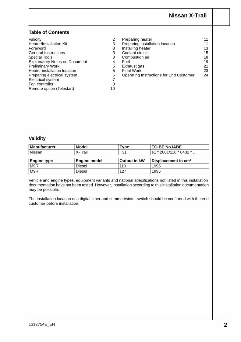
Table of Contents
Validity
Vehicle and engine types, equipment variants and national specifications not listed in this installation documentation have not been tested. However, installation according to this installation documentation may be possible.
The installation location of a digital timer and summer/winter switch should be confirmed with the end customer before installation.
Manufacturer Model Type EG-BE No./ABENissan X-Trail T31 e1 * 2001/116 * 0432 * ...
Engine type Engine model Output in kW Displacement in cm³M9R Diesel 110 1995M9R Diesel 127 1995
Validity 2Heater/Installation Kit 3Foreword 3General Instructions 3Special Tools 3Explanatory Notes on Document 4Preliminary Work 5Heater installation location 5Preparing electrical system 6Electrical system 7Fan controller 8Remote option (Telestart) 10
Preparing heater 11Preparing installation location 11Installing heater 13Coolant circuit 15Combustion air 18Fuel 19Exhaust gas 21Final Work 23Operating Instructions for End Customer 24
1312754E_EN 2
Nissan X-Trail
Heater/Installation Kit
Heater recommended for the respective vehicle class:
The selection of the heater is based on the passenger compartment size of the vehicle and the level of comfort required by the customer!
ForewordThis installation documentation applies to Nissan X-Trail Diesel vehicles - for validity, see page 2 - from model year 2008 and later, assuming technical modifications to the vehicle do not affect installation, any liability claims excluded. Depending on the vehicle version and equipment, modifications may be necessary during installation with respect to this installation documentation.
However, the stipulations in this "installation documentation", the "operating instructions" and "Installa-tion instructions" for the Thermo Top E / C / P should be observed under all circumstances.The corresponding rules of technology and any information from the vehicle manufacturer should be observed during the installation work.
General InstructionsInstallation should be carried out according to the general, standard rules of technology. Unless spec-ified otherwise, fasten hoses, lines and wiring harnesses to original vehicle lines and wiring harnesses using cable ties.Sharp edges must be provided with rub protection (cut-open fuel hose)!Spray unfinished body areas, e.g. drilled holes, with anti-corrosion wax (Tectyl 100K, Order No. 111329).When installing an IPCU, check or adjust the corresponding settings before installation!
Special Tools- Torque wrench for 2.0 - 10 Nm- Hose clamping pliers- Metric thread-setter kit
Quantity Description Order No.:1 Retail accessories Thermo Top E / C / P See Nissan price list1 Installation kit for Nissan X-Trail Diesel 1312668A1 Heater control See Nissan price list
Vehicle HeaterCompact car Thermo Top EMid-size car, station wagon Thermo Top CFull-size car, van, Offroader Thermo Top P
1312754E_EN 3

Nissan X-Trail
Explanatory Notes on Document
To provide you with a quick overview of the individual working steps, you will find an identification mark on the outside top right corner of the page in question.
1312754E_EN 4
Special features are highlighted using the following symbols:
The arrow in the vehicle icon indicates the position on the vehicle and the viewing angle.
Specific risk of injury or fatal accidents.
Specific risk of damage to components.
Specific risk of fire or explosion.
Reference to general installation instructions of Webas-to components or to the manufacturer's vehicle-specific documents.
Reference to a special technical feature.
All dimensions are in mm!Tightening torque of hose clamps = 2.0 + 0.5 Nm!Tightening torque of Ejot screws, Ejot studs = 10 Nm!
Mechanical system
Electrical system
Coolant circuit
Fuel
Exhaust gas
Combustion air

Nissan X-Trail
Preliminary Work
WARNING!
- Open fuel tank cap, ventilate tank.- Close the tank cap again.- Disconnect the battery "earth" or "ground" connection.- Depressurize the cooling system!- Copy the factory number from the original type label to the duplicate type label.- Remove years that do not apply from the duplicate label.- Attach the duplicate label (type label) in the appropriate place.- Remove the battery completely.- Remove the air filter together with the intake hose- Remove the trim in the right footwell- Remove the fuse and relay box.- Remove the A/C control panel.- Remove bumper.- Remove the underride protection.- Remove right underbody trim- Open the right-hand fuel sender service lid.
Remove page 24 "Operating Instructions for End Customer" and add to the vehicle operating instruc-tions.
Installa-tion loca-tion
Heater installation location
1 Heater
1
1
1312754E_EN 5

Nissan X-Trail
Cutting wires to length
Preparing fuse F4
Preparing electrical system
Only with automatic air-conditioning
Wire section 1 and 2 will be required later for connecting fuse F4.
Produce connections as shown in wiring dia-gram. Install wire section 2 in the protective sleeving provided.
1
100
2sw
0,75²
F4
86
85 30
87a87
K3
1 2
1312754E_EN 6
Nissan X-Trail
Wiring har-ness in-stallation diagram
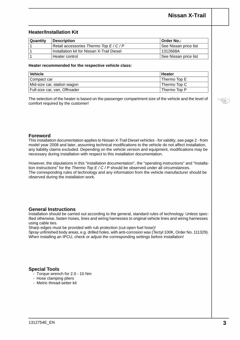
Electrical system
Digital timer
1 Digital timer
Summer/winter switch option
1 Summer/winter switch, drilled hole 12 mm dia.
Fuse holder, K3 relay
1 Fuse holder2 M5x12 bolt, washer [2x], retaining plate of
fuse holder, nut3 Angle bracket4 M6x20 bolt, large diameter washer, existing
hole, flanged nut5 K3 relay
Wiring harness pass through
1 Protective rubber plug
2
1
31
Do not install the metering pump cable harness until later together with fuel pipe along the original vehicle fuel lines on the under-body
4
32
5
1 4
5
1
1312754E_EN 7
Nissan X-Trail
Wiring dia-gram
Legend
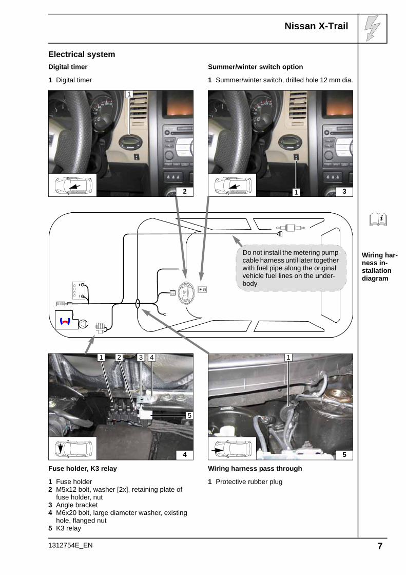
Fan controller
Webasto components Vehicle components Colours and symbolsHG Heater TT-C/E/P GM Fan motor rt redX1 6-pin heater connector KB A/C control panel ws whiteF3 25 A fuse M53 40-pin connector KB sw blackK3 Fan relay GRr Fan controller br brownF4 10A fuse M311 4-pin connector, GRr gn green
F1 10A fuse bl blueF8 10A fuse ge yellowF15 15A fuse Insulate wire ends and
tie backF16 15A fuseX Cutting pointWiring colours may vary.
Webasto
31
30
15
Nissan
HG
X1 4
F3
86
85 30
87a87
K3
rt/wsgn/ws
br
F4
sw
F15 F16
+
-
GMMsw
rtbl
F8 F1
KB
M53 22 21
8 7
GRr
M311 1
3 2
ge
sw
!
ws/gr
0,75²
0,75²
2²4²
bl2²
ge2²
ge2²
4²
ws/gr0,75²
1312754E_EN 8

Nissan X-Trail
Connect-ing fan-mo-tor
Connect-ing A/C control panel
View of connector M53
Connection to fuse box 6 behind fuses F15 and F16. Produce connections as shown in wiring diagram.
1 Yellow and blue (ge/bl) wire of fan motor2 Black (sw) wire from K3/303 Red (rt) wire from K3/87a4 Yellow (ge) wire from fuse 165 Blue (bl) wire of fuse 15
Connection to 40-pin connector 3 from A/C control element.Produce connections as shown in wiring dia-gram.
1 Black (sw) wire from F42 Insulate and tie back white/gray (ws/gr)
wire4 White/gray (ws/gr) wire, Pin 21
Connector imprint may differ from wiring diagram!
1 Connector M53 on line side
6
1
3
6
2
5 4
7
1
4
3
2
21
1
40
20
1
1312754E_EN 9
Nissan X-Trail
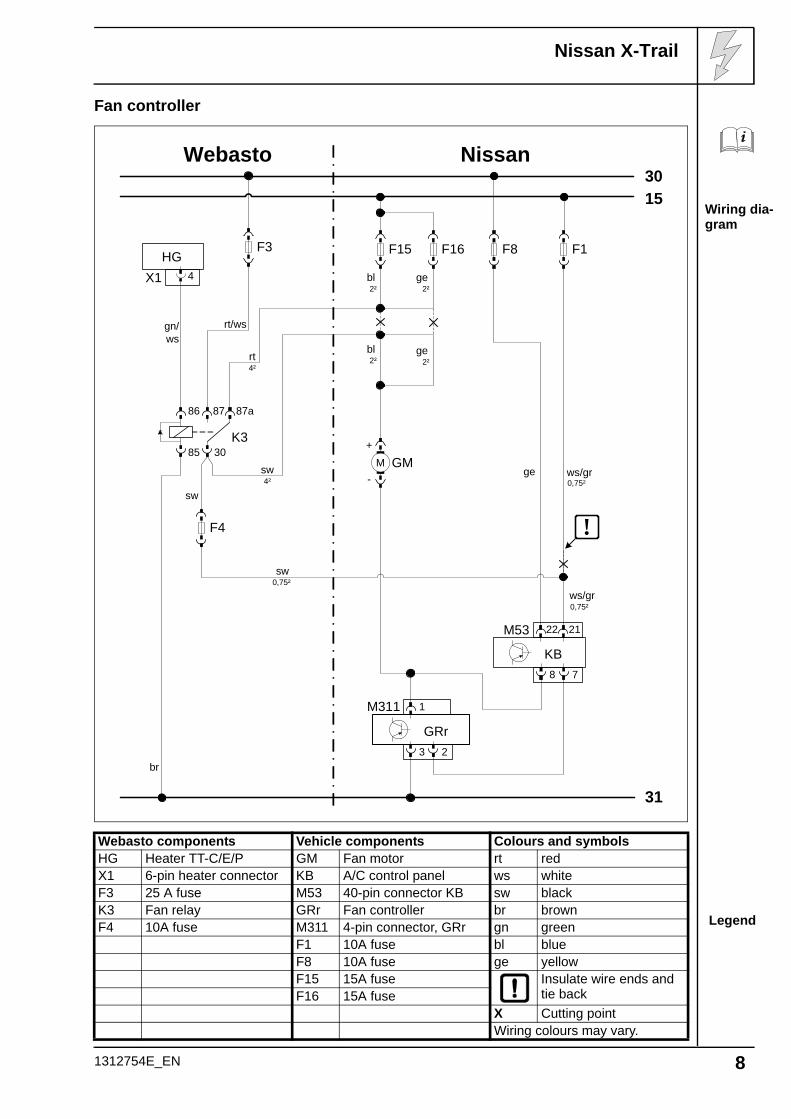
Installing receiver
Installing antenna
Installing tempera-ture sensor
Remote option (Telestart)
1 Fasten receiver with double-sided adhe-sive tape
1 Antenna
Temperature sensor only for T100 HTM
1 Fasten temperature sensor with double-sided adhesive tape
1 8
1
9
1
10
1312754E_EN 10
Nissan X-Trail
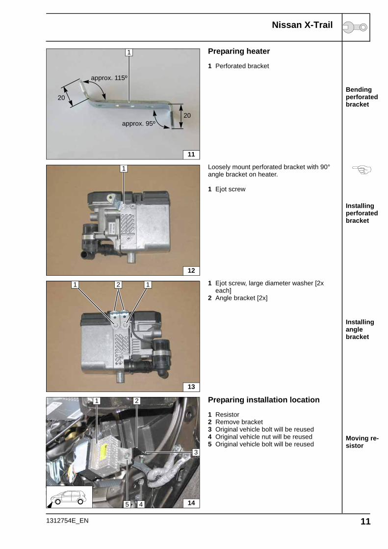
Bending perforated bracket
Installing perforated bracket
Installing angle bracket
Moving re-sistor
Preparing heater
1 Perforated bracket
Loosely mount perforated bracket with 90° angle bracket on heater.
1 Ejot screw
1 Ejot screw, large diameter washer [2x each]
2 Angle bracket [2x]
Preparing installation location
1 Resistor2 Remove bracket3 Original vehicle bolt will be reused4 Original vehicle nut will be reused5 Original vehicle bolt will be reused
1
approx. 115º
approx. 95º20
20
11
1
12
13
21 1
14
3
1 2
5 4
1312754E_EN 11
Nissan X-Trail
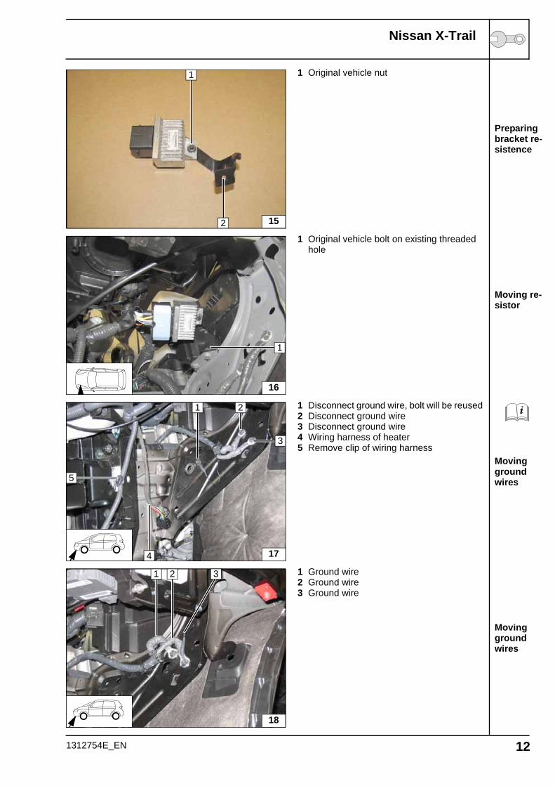
Preparing bracket re-sistence
Moving re-sistor
Moving ground wires
Moving ground wires
1 Original vehicle nut
1 Original vehicle bolt on existing threaded hole
1 Disconnect ground wire, bolt will be reused2 Disconnect ground wire3 Disconnect ground wire4 Wiring harness of heater5 Remove clip of wiring harness
1 Ground wire2 Ground wire3 Ground wire
15
1
2
16
1
17
3
1
4
2
5
18
1 2 3
1312754E_EN 12

Nissan X-Trail
Removing relay box
Fastening wiring har-ness
Offsetting relay box
Installing heater
If available, remove relay box 1. Discard ori-ginal vehicle bolt.
2 Detach clip of wiring harness
Route wiring harness and install clip 1 in the existing hole.
1 Original vehicle bolt in existing hole, large diameter washer, M6 flanged nut
Installing heater
1 Original vehicle bolt on existing threaded hole
2 Tighten Ejot screw
19
1
4
20
1
21
1
22
1
2
1312754E_EN 13

Nissan X-Trail
Installing heater
Installing heater
1 M6x20 bolt, M6 flanged nut2 Copy hole pattern, drill 6.5 mm dia. hole in
cross member
1 M6x20 bolt, M6 flanged nut
23
1
2
241
1312754E_EN 14

Nissan X-Trail
Hose rout-ing dia-gram
Coolant circuit
WARNING!Any coolant running off should be collected using an appropriate container! Install hoses so that they are kink-free. Unless specified otherwise, always fasten using cable ties. Position clamps so that no other hose can be damaged! When installing the coolant hose, the heater must be filled with coolant.The connection should be "inline" based on the following diagram:
All connecting pipes = dia. 20x20. All hose clamps = 20-27 mm dia.!1 = Original vehicle spring clip [2x]!
AB
C
1
1
D
1312754E_EN 15

Nissan X-Trail
Cutting hoses to length
Preparing hoses
Premount-ing hoses
Cutting point
Discard section X
A = 680C = 110D = 520
Push braided protection hoses onto hose A and D and cut to length.Cut heat shrink plastic tubing to size and shrink.
1 25 mm long heat shrink plastic tubing [4x]
Remove original vehicle hose on heat ex-changer outlet/engine inlet 1 and discard. Spring clip will be reused!
X
D
B
X A C
D
A
1
1 1
1
25
A B
D
C
26
1
1312754E_EN 16
Nissan X-Trail
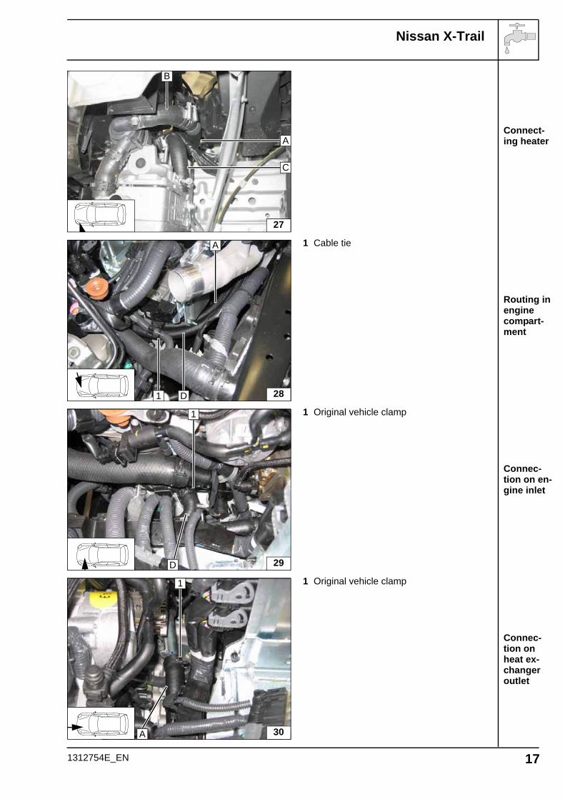
Connect-ing heater
Routing in engine compart-ment
Connec-tion on en-gine inlet
Connec-tion on heat ex-changer outlet
1 Cable tie
1 Original vehicle clamp
1 Original vehicle clamp
27
B
C
A
28
A
D1
29
1
D
30
1
A
1312754E_EN 17

Nissan X-Trail
Cutting combus-tion air pipe to length
Installing intake pipe
Installing muffler
Combustion air
1 Combustion air pipea = 280
Discard section X
1 27 mm dia. clamp2 Combustion-air intake pipe
1 Intake muffler2 Cable ties [2x] through guide slit
a
1
X
31
1 2
32
1
2
1312754E_EN 18

Nissan X-Trail
Connec-tion to heater
Installing lines
Installa-tion loca-tion of metering pump
Fuel
CAUTION!Open the vehicle's fuel tank cap, ventilate the tank and then re-close the tank lock.
Catch any fuel running off with an appropriate container.
Install fuel line and metering-pump wiring harness so that they are protected against stone impact. Un-less specified otherwise, always fasten using cable ties.Mount the fuel line and wiring harness with rub protection on sharp edges.
WARNING!The fuel line and wiring harness are routed to the metering pump in as shown in the wiring harness routing diagram.
1 Fuel line2 Hose bracket between fuel line and hose D3 Hose section, 10 mm dia. clamp [2x]
Route fuel line to right-hand side of vehicle, slide into 2x corrugated tube together with wi-ring harness of metering pump and route along original vehicle fuel line to installation location of metering pump.
1 Corrugated tube with fuel line and wiring harness for metering pump
1 Angle bracket, hole drilled out to 10.5 mm dia.
2 Original vehicle bolt
333
1
2
34
1
35
1 2
1312754E_EN 19

Nissan X-Trail
Installing metering pump
Removing fuel
Connect-ing to me-tering pump
1 Metering pump2 Rubber-coated p-clamp, silent block,
flanged nut [2x]3 Hose section, 10 mm dia. clamp [2x]4 Fuel line5 Wiring harness of metering pump, connec-
tor mounted
Separate fuel return line 4 approx. 50 mm be-fore coupling.
1 Fuel line2 Hose section, 10 mm dia. clamp [2x]3 6x5x6 fuel standpipe, 8 mm dia. clamp [2x]
Check the position of the components; adjust if necessary. Check that they have free clear-ance.
1 Fuel line2 Hose section, 10 mm dia. clamp [2x]
362
1
5
3
4
37
1
2
34
38
1
2
1312754E_EN 20

Nissan X-Trail
Preparing exhaust pipe
Installing muffler
Installing muffler
Installing exhaust pipe
Exhaust gas
1 Exhaust pipea = 260
2 Exhaust end sectionb = 250
Discard section X
1 Ejot stud
1 Exhaust muffler2 M6x30 spacer nut3 M6x12 bolt, spring lockwasher
1 Exhaust pipe2 Hose clamp [2x]
a b
1 2
X
391
1
2
3
40
1
2
2
41
1312754E_EN 21

Nissan X-Trail
Installing exhaust end sec-tion
Mounting rubber iso-lator
1 Hose clamp2 Exhaust end section
Drill out existing hole in wheel-well inner panel 1 to 42 mm dia.Insert exhaust end section 3 and red rubber isolator 2 in hole. Align exhaust end section 3 flush on red rubber isolator 2.
1 2
42
2
43
1
3
1312754E_EN 22

Nissan X-Trail
Final Work
WARNING!Mount removed parts in reverse order. Check all hoses, clamps and all electrical connections for firm seating. Insulate all loose wires and tie back.Only use manufacturer-approved coolant. Spray the heater components with anti-corrosion wax (Tectyl 100K, Order No. 111329).
- Connect the battery.- Fill and bleed the coolant circuit according to the vehicle manufacturer’s specifications.- Adjust digital timer, try out Telestart transmitter- Make settings on A/C control panel according to the "Operating Instructions for End Custo-
mer".- Apply the label "Switch off parking heater before refilling" in the area of the filling neck- For initial start-up and function check, see installation instructions
1312754E_EN Printed in Germany 02/2011 Printing: Steffen 23
Feel the driveWebasto AGPostfach 80D-82132 Stockdorf / GermanyNational Hotline: 01805 93 22 78(14 Cent aus dem deutschen Festnetz)Hotfax: 0395 5592 353Hotmail: [email protected]://www.webasto.de

Nissan X-Trail
Automatic air-condi-tioning
Automatic air-condi-tioning
Operating Instructions for End Customer
Please remove page and add to the vehicle operating instructions.
Note:We recommend matching the heating time to the driving time.Heating time = driving timeExample:For a driving time of approx. 20 min. (in one direction), we recommend not exceeding a switch-on time of 20 min.
If the summer/winter switch option has been installed, this must be switched in accordance with the time of year. The heater will then only switch on the vehicle fan to ventilate the vehicle interior in the position Winter heat and in the position Summer .
Before parking the vehicle, make the following settings:
Version 1
1 Air outlet to windshield2 Adjust fan as shown3 Set temperature to "max."
Version 2
2 Air outlet to windshield1 Adjust fan as shown3 Set temperature to "max."
44
1 2
3
45
1 2
3
1312754E_EN 24
Related Documents