Feel the drive WARNING! Hazard warning: Incorrect installation or repair of Webasto heating systems may cause a fire or result in the emission of carbon monoxide, which can be fatal. Serious or fatal injuries can be caused as a result. Specialist company training, technical documentation, specialised tools and equipment are required to install and repair Webasto heating and cooling systems. Only original Webasto parts must be used. For this, also see the catalog of air and water heat- er accessories from Webasto. NEVER attempt to install or repair Webasto heating or cooling systems if you have not successfully completed the company training and thereby acquired the required tech- nical skills, or if you do not have access to the required technical documentation, tools and equipment needed to carry out correct installation and repairs. ALWAYS follow all Webasto installation and repair instructions and observe all warnings. The initial startup is to be executed with the Webasto Thermo Test Diagnosis. Webasto does not accept any liability for defects and damage that are attributable to installa- tion by untrained staff. Water Heater Installation documentation Ident. No.: 1317500C_EN Fee Euro 10.00 © Webasto AG Audi A6 / A6- Avant / Audi A7 Sportback 2.0 and 3.0 TDI quattro from model year 2011 Left-hand drive vehicle Automatic transmission Climatronic Thermo Top Evo Parking Heater e1 00 0258

Welcome message from author
This document is posted to help you gain knowledge. Please leave a comment to let me know what you think about it! Share it to your friends and learn new things together.
Transcript
Feel the drive
WARNING!
Hazard warning:
Incorrect installation or repair of Webasto heating systems may cause a fire or result in the emission of carbon monoxide, which can be fatal. Serious or fatal injuries can be caused as a result.
Specialist company training, technical documentation, specialised tools and equipment are required to install and repair Webasto heating and cooling systems.Only original Webasto parts must be used. For this, also see the catalog of air and water heat-er accessories from Webasto.
NEVER attempt to install or repair Webasto heating or cooling systems if you have not successfully completed the company training and thereby acquired the required tech-nical skills, or if you do not have access to the required technical documentation, tools and equipment needed to carry out correct installation and repairs.
ALWAYS follow all Webasto installation and repair instructions and observe all warnings.
The initial startup is to be executed with the Webasto Thermo Test Diagnosis.
Webasto does not accept any liability for defects and damage that are attributable to installa-tion by untrained staff.
Water Heater
Installation documentation
Ident. No.: 1317500C_EN Fee Euro 10.00 © Webasto AG
Audi A6 / A6- Avant /Audi A7 Sportback
2.0 and 3.0 TDI quattro
from model year 2011
Left-hand drive vehicle
Automatic transmission
Climatronic
Thermo Top Evo Parking Heatere1
00 0258
Audi A6 / A6- Avant / Audi A7 Sportback
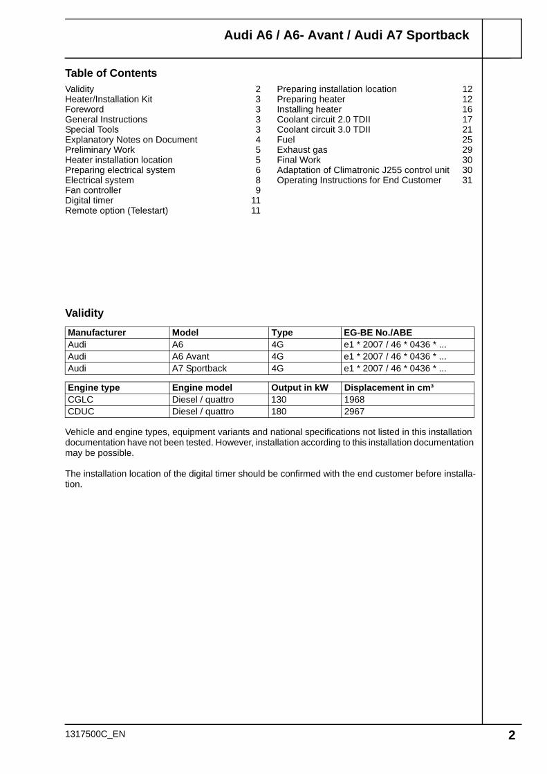
Table of Contents
Validity
Vehicle and engine types, equipment variants and national specifications not listed in this installation documentation have not been tested. However, installation according to this installation documentation may be possible.
The installation location of the digital timer should be confirmed with the end customer before installa-tion.
Manufacturer Model Type EG-BE No./ABEAudi A6 4G e1 * 2007 / 46 * 0436 * ...Audi A6 Avant 4G e1 * 2007 / 46 * 0436 * ...Audi A7 Sportback 4G e1 * 2007 / 46 * 0436 * ...
Engine type Engine model Output in kW Displacement in cm³CGLC Diesel / quattro 130 1968CDUC Diesel / quattro 180 2967
Validity 2Heater/Installation Kit 3Foreword 3General Instructions 3Special Tools 3Explanatory Notes on Document 4Preliminary Work 5Heater installation location 5Preparing electrical system 6Electrical system 8Fan controller 9Digital timer 11Remote option (Telestart) 11
Preparing installation location 12Preparing heater 12Installing heater 16Coolant circuit 2.0 TDII 17Coolant circuit 3.0 TDII 21Fuel 25Exhaust gas 29Final Work 30Adaptation of Climatronic J255 control unit 30Operating Instructions for End Customer 31
1317500C_EN 2
Audi A6 / A6- Avant / Audi A7 Sportback
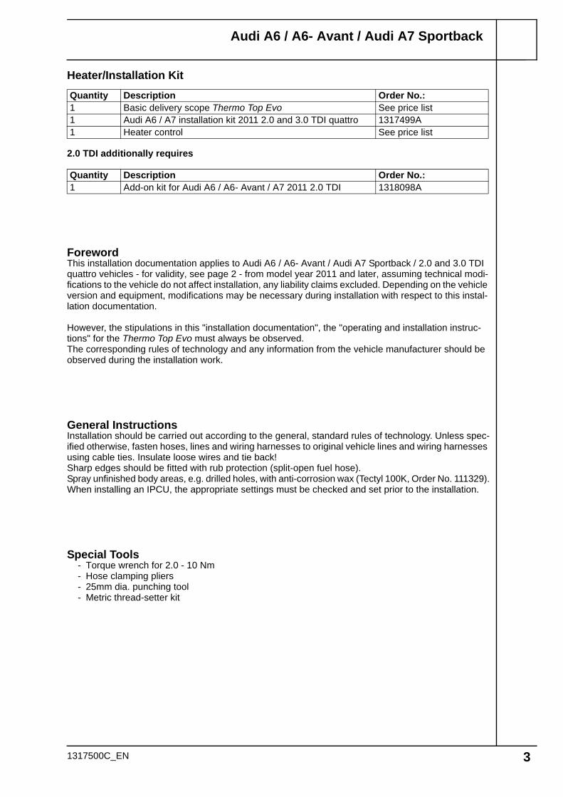
Heater/Installation Kit
2.0 TDI additionally requires
ForewordThis installation documentation applies to Audi A6 / A6- Avant / Audi A7 Sportback / 2.0 and 3.0 TDI quattro vehicles - for validity, see page 2 - from model year 2011 and later, assuming technical modi-fications to the vehicle do not affect installation, any liability claims excluded. Depending on the vehicle version and equipment, modifications may be necessary during installation with respect to this instal-lation documentation.
However, the stipulations in this "installation documentation", the "operating and installation instruc-tions" for the Thermo Top Evo must always be observed.The corresponding rules of technology and any information from the vehicle manufacturer should be observed during the installation work.
General InstructionsInstallation should be carried out according to the general, standard rules of technology. Unless spec-ified otherwise, fasten hoses, lines and wiring harnesses to original vehicle lines and wiring harnesses using cable ties. Insulate loose wires and tie back!Sharp edges should be fitted with rub protection (split-open fuel hose).Spray unfinished body areas, e.g. drilled holes, with anti-corrosion wax (Tectyl 100K, Order No. 111329).When installing an IPCU, the appropriate settings must be checked and set prior to the installation.
Special Tools- Torque wrench for 2.0 - 10 Nm- Hose clamping pliers- 25mm dia. punching tool- Metric thread-setter kit
Quantity Description Order No.:1 Basic delivery scope Thermo Top Evo See price list1 Audi A6 / A7 installation kit 2011 2.0 and 3.0 TDI quattro 1317499A1 Heater control See price list
Quantity Description Order No.:1 Add-on kit for Audi A6 / A6- Avant / A7 2011 2.0 TDI 1318098A
1317500C_EN 3
Audi A6 / A6- Avant / Audi A7 Sportback
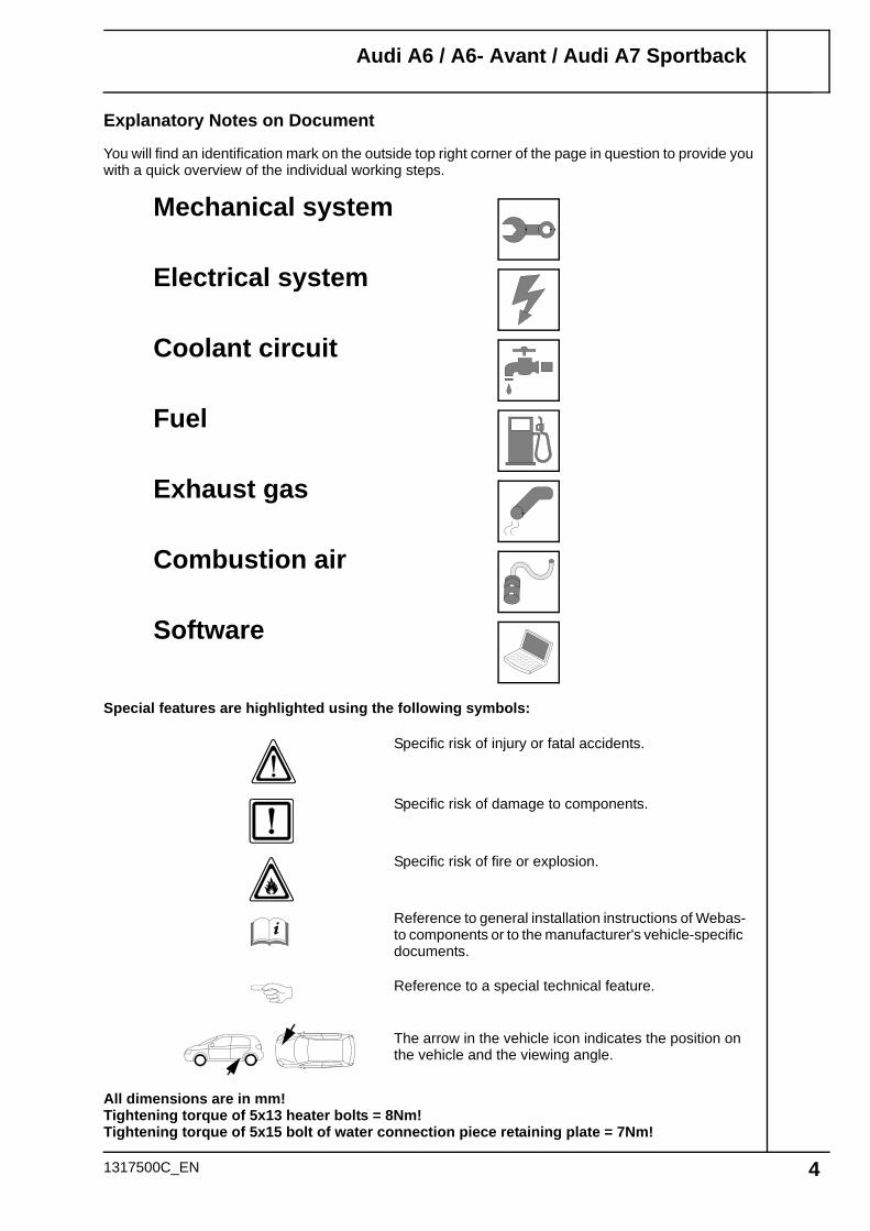
Explanatory Notes on Document
You will find an identification mark on the outside top right corner of the page in question to provide you with a quick overview of the individual working steps.
1317500C_EN 4
Special features are highlighted using the following symbols:
The arrow in the vehicle icon indicates the position on the vehicle and the viewing angle.
Specific risk of injury or fatal accidents.
Specific risk of damage to components.
Specific risk of fire or explosion.
Reference to general installation instructions of Webas-to components or to the manufacturer's vehicle-specific documents.
Reference to a special technical feature.
Mechanical system
Electrical system
Coolant circuit
Fuel
Exhaust gas
Combustion air
Software
All dimensions are in mm!Tightening torque of 5x13 heater bolts = 8Nm!Tightening torque of 5x15 bolt of water connection piece retaining plate = 7Nm!
Audi A6 / A6- Avant / Audi A7 Sportback
Preliminary Work
WARNING!
- Open the fuel tank cap, ventilate the tank.- Close the fuel tank cap again.- Depressurise the cooling system.- Copy the factory number from the original type label to the duplicate type label.- Remove years that do not apply from the duplicate label.- Attach the duplicate label (type label) in the appropriate place.- Disconnect the battery (luggage compartment).- Remove the engine design cover.- Remove the air filter together with the intake hose.- Remove the right-hand front wheel.- Remove the right-hand front wheel well trim.- Remove the right-hand underride protection.- Remove the front underride protection, located in the centre.- Remove the rear bench seat.- Remove the fuel-tank sending unit in accordance with the manufacturer's instructions.- Remove the lower instrument panel trim on the front passenger's side.- Remove the glove compartment.- Remove the A-pillar trim on the front passenger's side.- Remove the A/C control panel in accordance with the manufacturer's instructions.
Remove page 31 "Operating Instructions for End Customer" and add to the vehicle operating instruc-tions.
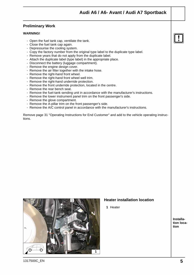
Installa-tion loca-tion
Heater installation location
1 Heater
1
1
1317500C_EN 5
Audi A6 / A6- Avant / Audi A7 Sportback
Cutting wiring har-ness of metering pump to length
Preparing additional lines
Preparing time-delay relay
Preparing perforated bracket
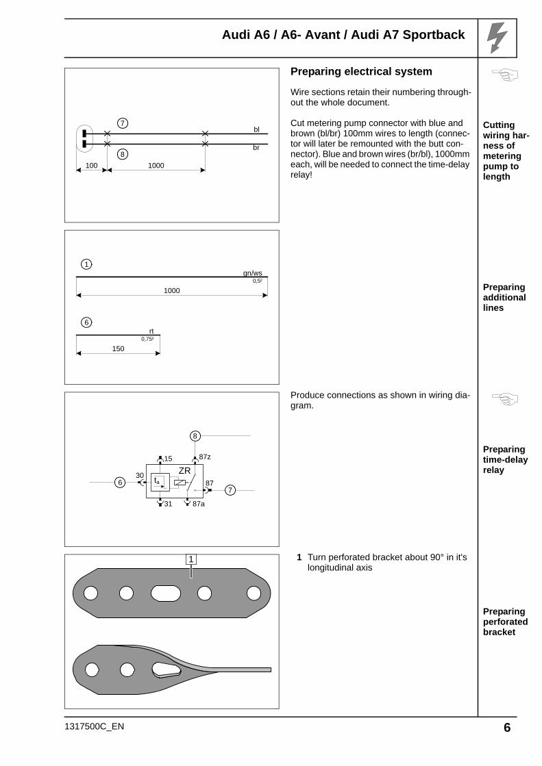
Preparing electrical system
Wire sections retain their numbering through-out the whole document.
Cut metering pump connector with blue and brown (bl/br) 100mm wires to length (connec-tor will later be remounted with the butt con-nector). Blue and brown wires (br/bl), 1000mm each, will be needed to connect the time-delay relay!
Produce connections as shown in wiring dia-gram.
1 Turn perforated bracket about 90° in it's longitudinal axis
7
1000
bl
100
br8
1
1000
gn/ws0,5²
6
150
rt0,75²
15
31
87
ZR30
ta
87z
87a
8
76
1
1317500C_EN 6
Audi A6 / A6- Avant / Audi A7 Sportback
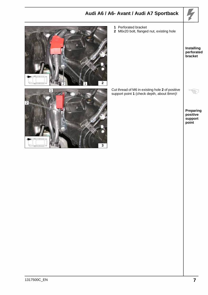
Installing perforated bracket
Preparing positive support point
1 Perforated bracket2 M6x20 bolt, flanged nut, existing hole
Cut thread of M6 in existing hole 2 of positive support point 1 (check depth, about 8mm)!
22 1
3
1
2
1317500C_EN 7
Audi A6 / A6- Avant / Audi A7 Sportback
Wiring har-ness rout-ing diagram
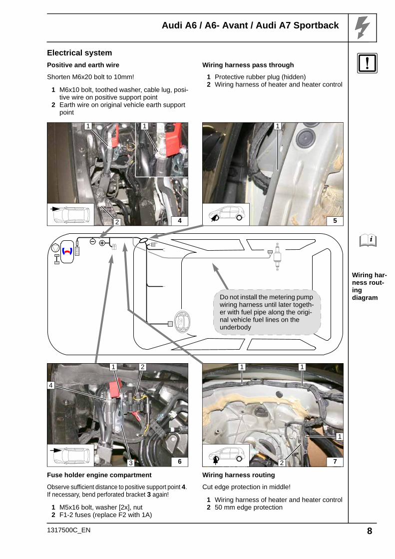
Electrical system
Positive and earth wire
Shorten M6x20 bolt to 10mm!
1 M6x10 bolt, toothed washer, cable lug, posi-tive wire on positive support point
2 Earth wire on original vehicle earth support point
Wiring harness pass through
1 Protective rubber plug (hidden)2 Wiring harness of heater and heater control
Fuse holder engine compartment
Observe sufficient distance to positive support point 4. If necessary, bend perforated bracket 3 again!
1 M5x16 bolt, washer [2x], nut2 F1-2 fuses (replace F2 with 1A)
Wiring harness routing
Cut edge protection in middle!
1 Wiring harness of heater and heater control2 50 mm edge protection
4
1
2
1
5
1
Do not install the metering pump wiring harness until later togeth-er with fuel pipe along the origi-nal vehicle fuel lines on the underbody
6
1 2
3
4
7
1
2
1
1
1317500C_EN 8
Audi A6 / A6- Avant / Audi A7 Sportback
Wiring dia-gram
Legend
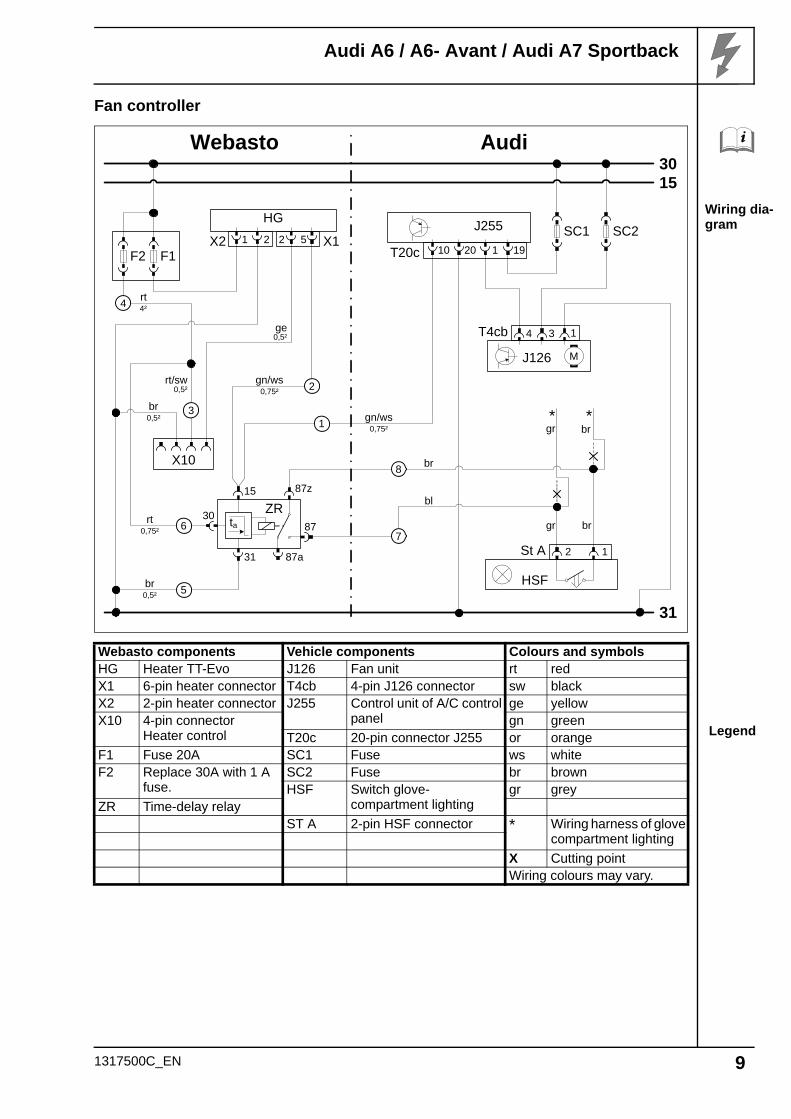
Fan controller
Webasto components Vehicle components Colours and symbolsHG Heater TT-Evo J126 Fan unit rt redX1 6-pin heater connector T4cb 4-pin J126 connector sw blackX2 2-pin heater connector J255 Control unit of A/C control
panelge yellow
X10 4-pin connectorHeater control
gn greenT20c 20-pin connector J255 or orange
F1 Fuse 20A SC1 Fuse ws whiteF2 Replace 30A with 1 A
fuse.SC2 Fuse br brownHSF Switch glove-
compartment lightinggr grey
ZR Time-delay relayST A 2-pin HSF connector * Wiring harness of glove
compartment lighting
X Cutting pointWiring colours may vary.
Webasto
31
3015
Audi
HG
X2 1 2 X152
F2 F1
ge0,5²
rt/sw0,5²
rt4²
X10
br0,5²
br0,5² gn/ws
0,75²1
5
4
3
2
SC1 SC2
HSF
St A 2 1
J255
T20c 10 20 191
6
15
31
87
ZR30
ta
87z
87a
rt0,75²
gn/ws0,75²
bl
br
gr
J126 M
T4cb 4 3 1
* *gr
br
br
7
8
1317500C_EN 9
Audi A6 / A6- Avant / Audi A7 Sportback
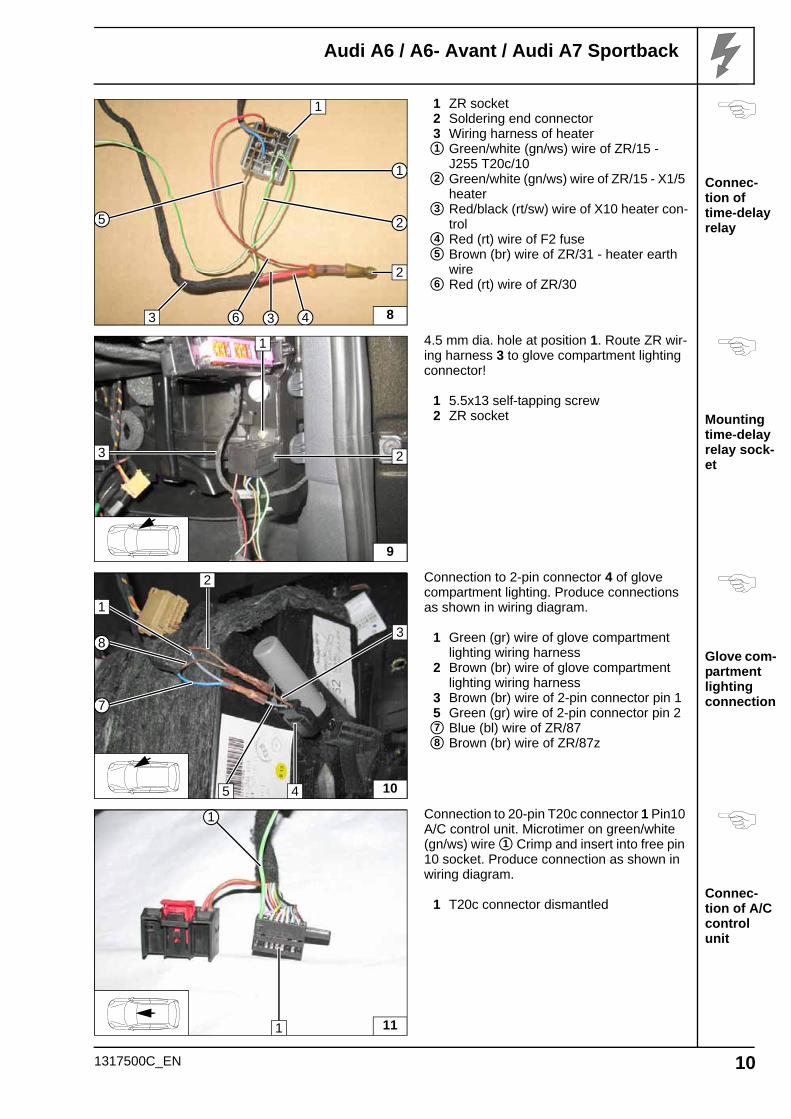
Connec-tion of time-delay relay
Mounting time-delay relay sock-et
Glove com-partment lighting connection
Connec-tion of A/C control unit
1 ZR socket2 Soldering end connector3 Wiring harness of heater
Green/white (gn/ws) wire of ZR/15 - J255 T20c/10Green/white (gn/ws) wire of ZR/15 - X1/5 heaterRed/black (rt/sw) wire of X10 heater con-trolRed (rt) wire of F2 fuseBrown (br) wire of ZR/31 - heater earth wireRed (rt) wire of ZR/30
4.5 mm dia. hole at position 1. Route ZR wir-ing harness 3 to glove compartment lighting connector!
1 5.5x13 self-tapping screw2 ZR socket
Connection to 2-pin connector 4 of glove compartment lighting. Produce connections as shown in wiring diagram.
1 Green (gr) wire of glove compartment lighting wiring harness
2 Brown (br) wire of glove compartment lighting wiring harness
3 Brown (br) wire of 2-pin connector pin 1 5 Green (gr) wire of 2-pin connector pin 2
Blue (bl) wire of ZR/87Brown (br) wire of ZR/87z
Connection to 20-pin T20c connector 1 Pin10 A/C control unit. Microtimer on green/white (gn/ws) wire Crimp and insert into free pin 10 socket. Produce connection as shown in wiring diagram.
1 T20c connector dismantled
8
1
46 3
2
1
5
2
3
1
2
3
4
5
6
9
1
23
104
7
3
5
8
1
2
7
8
111
1
1
1317500C_EN 10
Audi A6 / A6- Avant / Audi A7 Sportback
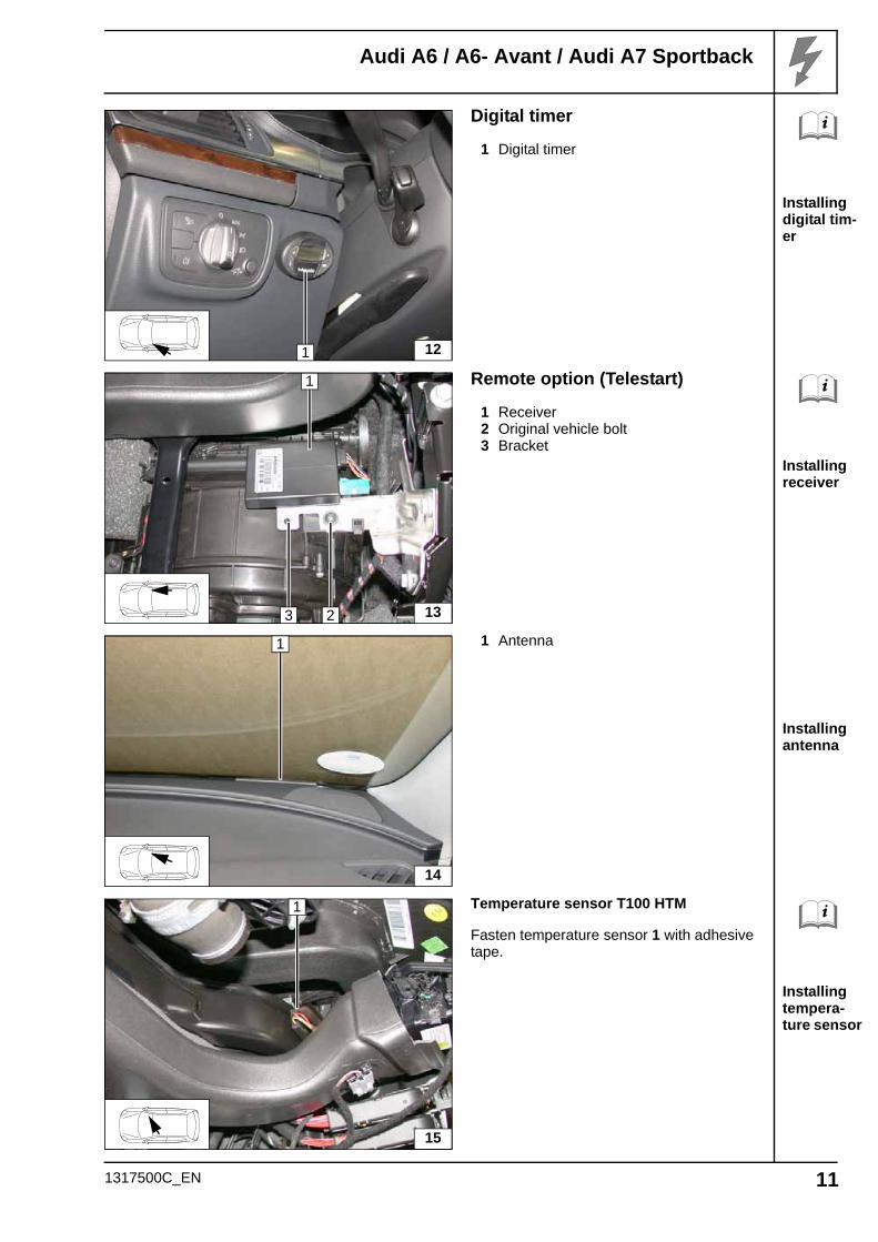
Installing digital tim-er
Installing receiver
Installing antenna
Installing tempera-ture sensor
Digital timer
1 Digital timer
Remote option (Telestart)
1 Receiver2 Original vehicle bolt3 Bracket
1 Antenna
Temperature sensor T100 HTM
Fasten temperature sensor 1 with adhesive tape.
1 12
1
2 133
1
14
1
15
1317500C_EN 11
Audi A6 / A6- Avant / Audi A7 Sportback
Installing rivet nut
Installing edge pro-tection
Routing wiring har-ness of heater
Assem-bling wa-ter connec-tion piece
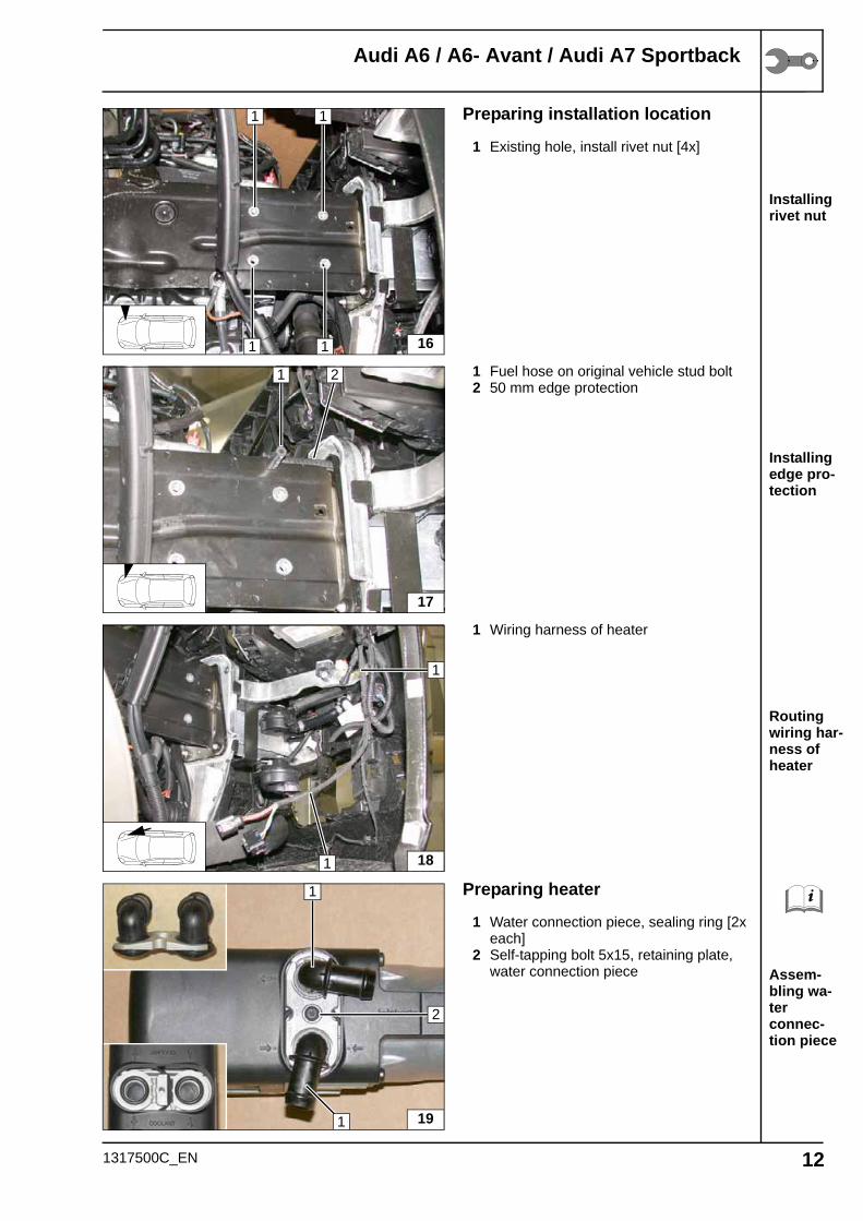
Preparing installation location
1 Existing hole, install rivet nut [4x]
1 Fuel hose on original vehicle stud bolt2 50 mm edge protection
1 Wiring harness of heater
Preparing heater
1 Water connection piece, sealing ring [2x each]
2 Self-tapping bolt 5x15, retaining plate, water connection piece
16
1 1
1 1
17
1 2
181
1
191
1
2
1317500C_EN 12
Audi A6 / A6- Avant / Audi A7 Sportback
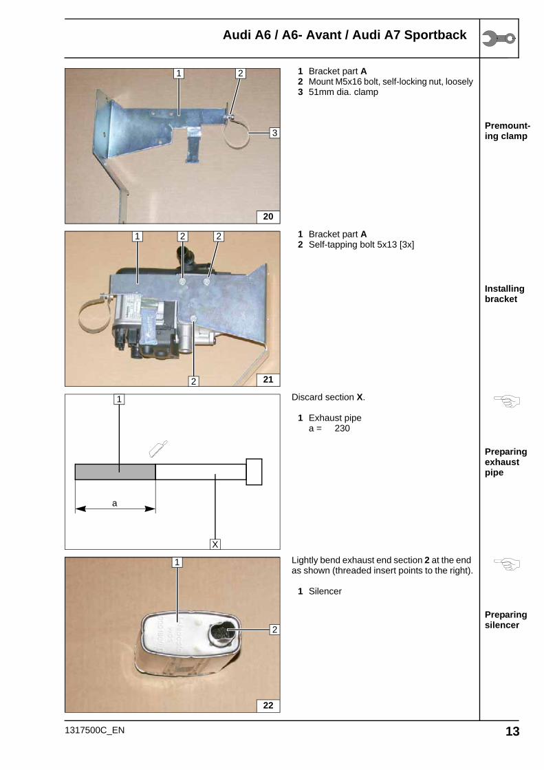
Premount-ing clamp
Installing bracket
Preparing exhaust pipe
Preparing silencer
1 Bracket part A2 Mount M5x16 bolt, self-locking nut, loosely3 51mm dia. clamp
1 Bracket part A2 Self-tapping bolt 5x13 [3x]
Discard section X.
1 Exhaust pipea = 230
Lightly bend exhaust end section 2 at the end as shown (threaded insert points to the right).
1 Silencer
20
3
1 2
21
2 2
2
1
a
1
X
22
2
1
1317500C_EN 13
Audi A6 / A6- Avant / Audi A7 Sportback
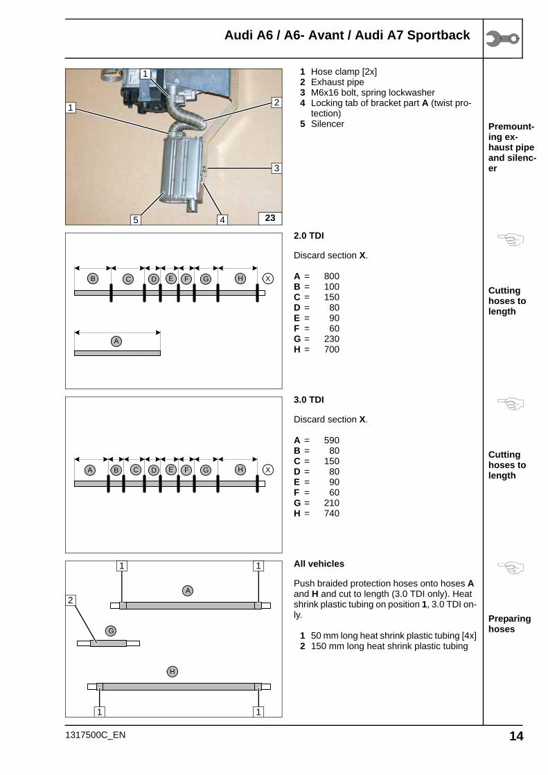
Premount-ing ex-haust pipe and silenc-er
Cutting hoses to length
Cutting hoses to length
Preparing hoses
1 Hose clamp [2x]2 Exhaust pipe3 M6x16 bolt, spring lockwasher4 Locking tab of bracket part A (twist pro-
tection)5 Silencer
2.0 TDI
Discard section X.
A = 800B = 100C = 150D = 80E = 90F = 60G = 230H = 700
3.0 TDI
Discard section X.
A = 590B = 80C = 150D = 80E = 90F = 60G = 210H = 740
All vehicles
Push braided protection hoses onto hoses A and H and cut to length (3.0 TDI only). Heat shrink plastic tubing on position 1, 3.0 TDI on-ly.
1 50 mm long heat shrink plastic tubing [4x]2 150 mm long heat shrink plastic tubing
23
2
1
4
3
1
5
A
B XC D E F G H
A B XC D E F G H
H
A
G
1 1
1 1
2
1317500C_EN 14
Audi A6 / A6- Avant / Audi A7 Sportback
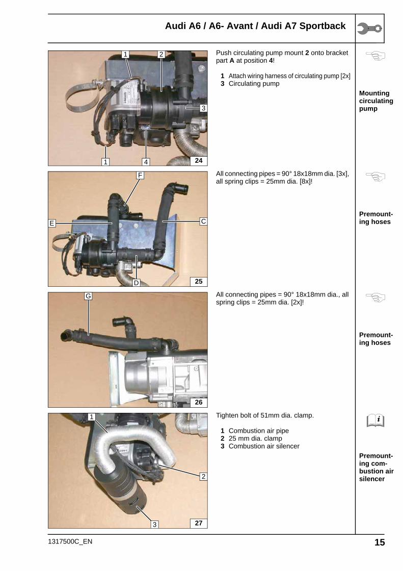
Mounting circulating pump
Premount-ing hoses
Premount-ing hoses
Premount-ing com-bustion air silencer
Push circulating pump mount 2 onto bracket part A at position 4!
1 Attach wiring harness of circulating pump [2x]3 Circulating pump
All connecting pipes = 90° 18x18mm dia. [3x], all spring clips = 25mm dia. [8x]!
All connecting pipes = 90° 18x18mm dia., all spring clips = 25mm dia. [2x]!
Tighten bolt of 51mm dia. clamp.
1 Combustion air pipe2 25 mm dia. clamp3 Combustion air silencer
2
1
3
24
1
4
CE
25
F
D
26
G
27
2
1
3
1317500C_EN 15
Audi A6 / A6- Avant / Audi A7 Sportback
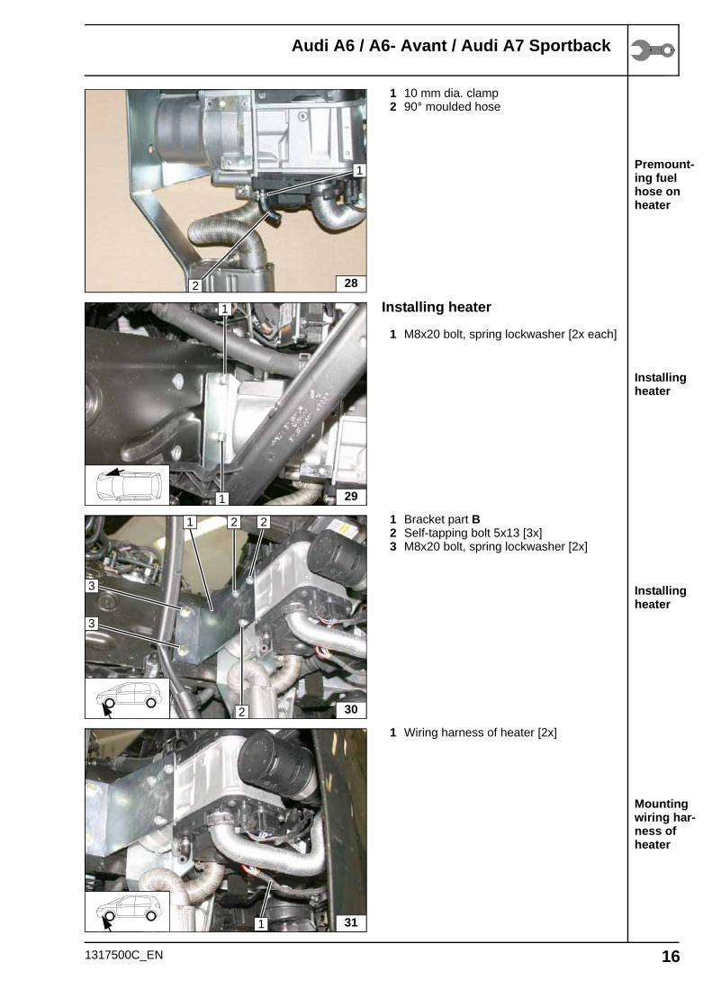
Premount-ing fuel hose on heater
Installing heater
Installing heater
Mounting wiring har-ness of heater
1 10 mm dia. clamp2 90° moulded hose
Installing heater
1 M8x20 bolt, spring lockwasher [2x each]
1 Bracket part B2 Self-tapping bolt 5x13 [3x]3 M8x20 bolt, spring lockwasher [2x]
1 Wiring harness of heater [2x]
28
1
2
29
1
1
30
1 2
2
3
3
2
311
1317500C_EN 16
Audi A6 / A6- Avant / Audi A7 Sportback
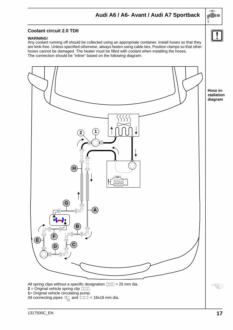
Hose in-stallation diagram
Coolant circuit 2.0 TDII
WARNING!Any coolant running off should be collected using an appropriate container. Install hoses so that they are kink-free. Unless specified otherwise, always fasten using cable ties. Position clamps so that other hoses cannot be damaged. The heater must be filled with coolant when installing the hoses.The connection should be "inline" based on the following diagram:
All spring clips without a specific designation = 25 mm dia.2 = Original vehicle spring clip .1= Original vehicle circulating pump.All connecting pipes and = 18x18 mm dia.
G
B
DE
F
C
A
12
H
1317500C_EN 17
Audi A6 / A6- Avant / Audi A7 Sportback
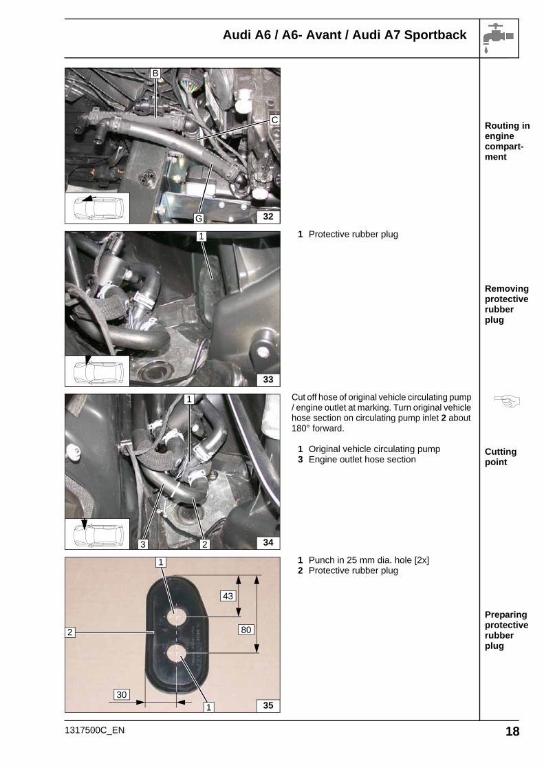
Routing in engine compart-ment
Removing protective rubber plug
Cutting point
Preparing protective rubber plug
1 Protective rubber plug
Cut off hose of original vehicle circulating pump / engine outlet at marking. Turn original vehicle hose section on circulating pump inlet 2 about 180° forward.
1 Original vehicle circulating pump3 Engine outlet hose section
1 Punch in 25 mm dia. hole [2x]2 Protective rubber plug
32
B
G
C
33
1
3423
1
35
1
43
80
301
2
1317500C_EN 18
Audi A6 / A6- Avant / Audi A7 Sportback
Installing p-clamps
Premount-ing hose A and H
Routing in engine compart-ment
Connect-ing hoses
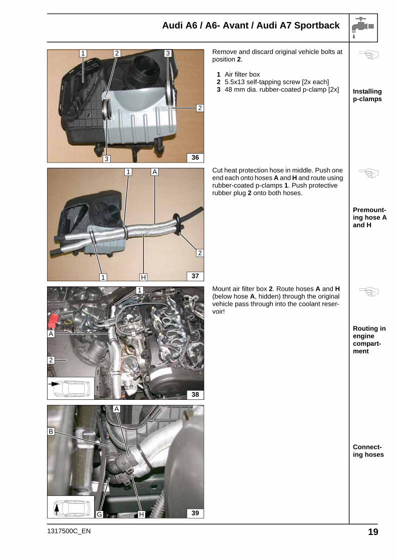
Remove and discard original vehicle bolts at position 2.
1 Air filter box2 5.5x13 self-tapping screw [2x each]3 48 mm dia. rubber-coated p-clamp [2x]
Cut heat protection hose in middle. Push one end each onto hoses A and H and route using rubber-coated p-clamps 1. Push protective rubber plug 2 onto both hoses.
Mount air filter box 2. Route hoses A and H (below hose A, hidden) through the original vehicle pass through into the coolant reser-voir!
36
3
2
3
1 2
37
A
2
1
1
H
38
2
1
A
39
A
G
B
H
1317500C_EN 19
Audi A6 / A6- Avant / Audi A7 Sportback
Connec-tion of heat exchanger inlet
Connect-ing engine outlet
Aligning hoses
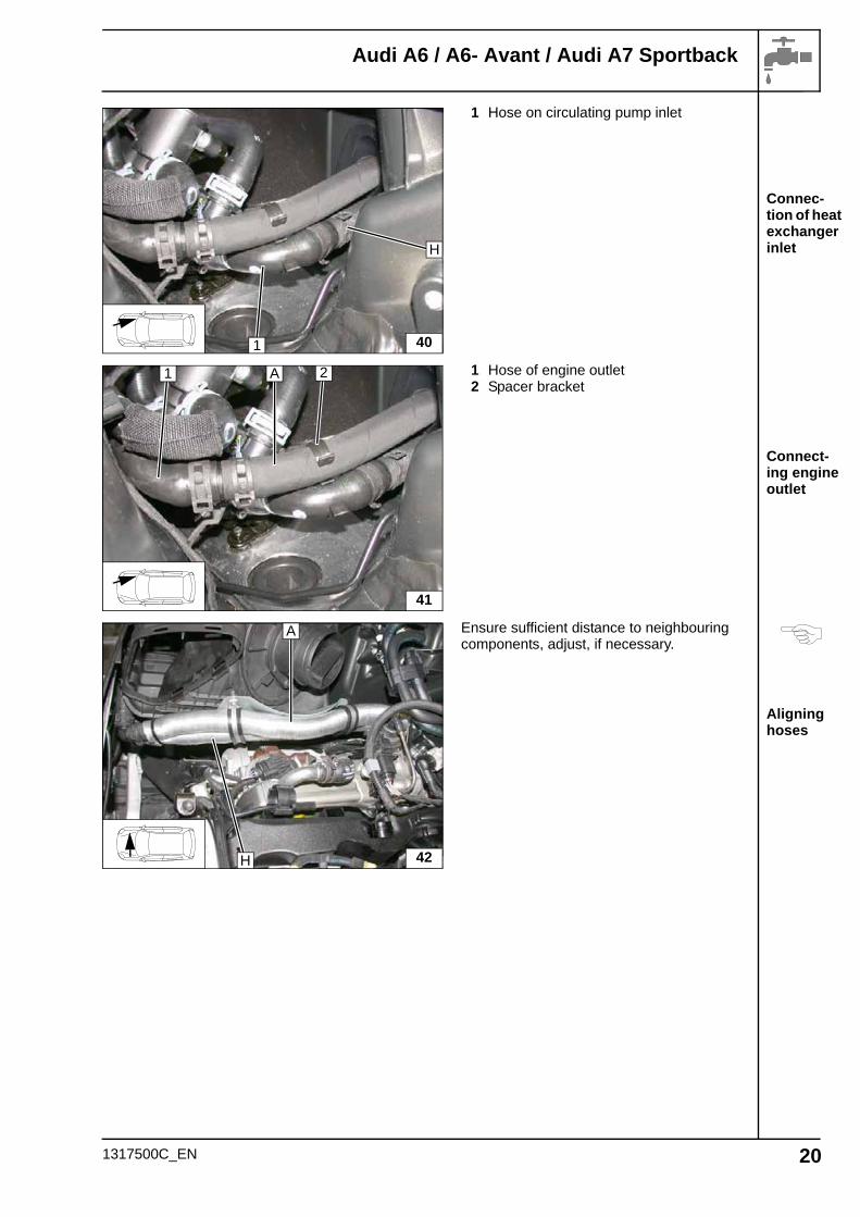
1 Hose on circulating pump inlet
1 Hose of engine outlet2 Spacer bracket
Ensure sufficient distance to neighbouring components, adjust, if necessary.
401
H
41
1 A 2
42H
A
1317500C_EN 20
Audi A6 / A6- Avant / Audi A7 Sportback
Hose in-stallation diagram
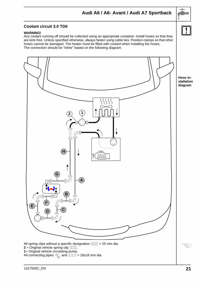
Coolant circuit 3.0 TDII
WARNING!Any coolant running off should be collected using an appropriate container. Install hoses so that they are kink-free. Unless specified otherwise, always fasten using cable ties. Position clamps so that other hoses cannot be damaged. The heater must be filled with coolant when installing the hoses.The connection should be "inline" based on the following diagram:
All spring clips without a specific designation = 25 mm dia.2 = Original vehicle spring clip .1= Original vehicle circulating pump.All connecting pipes and = 18x18 mm dia.
G
H
B
DE
F
C
A
12
1317500C_EN 21
Audi A6 / A6- Avant / Audi A7 Sportback
Installing p-clamp
Connect-ing heater outlet
Routing in engine compart-ment
Cutting point
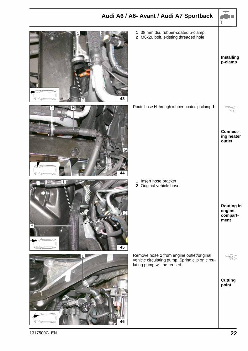
1 38 mm dia. rubber-coated p-clamp2 M6x20 bolt, existing threaded hole
Route hose H through rubber-coated p-clamp 1.
1 Insert hose bracket2 Original vehicle hose
Remove hose 1 from engine outlet/original vehicle circulating pump. Spring clip on circu-lating pump will be reused.
43
1
2
44
H
G
1
45
2
H
1
46
1
1317500C_EN 22
Audi A6 / A6- Avant / Audi A7 Sportback
Cutting point
Connec-tion of heat exchanger inlet
Connect-ing heater inlet
Routing in engine compart-ment
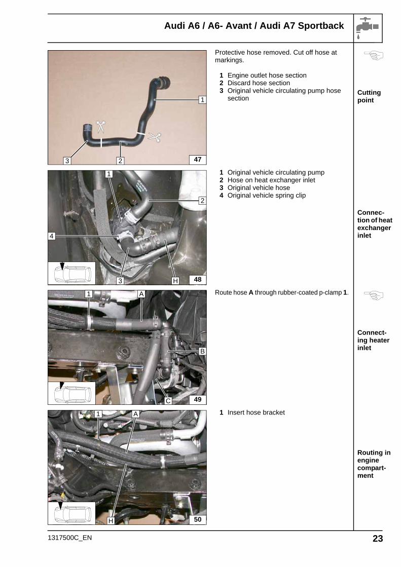
Protective hose removed. Cut off hose at markings.
1 Engine outlet hose section2 Discard hose section3 Original vehicle circulating pump hose
section
1 Original vehicle circulating pump2 Hose on heat exchanger inlet3 Original vehicle hose4 Original vehicle spring clip
Route hose A through rubber-coated p-clamp 1.
1 Insert hose bracket
47
1
23
48H
2
4
1
3
49
A
B
1
C
50
1 A
H
1317500C_EN 23
Audi A6 / A6- Avant / Audi A7 Sportback
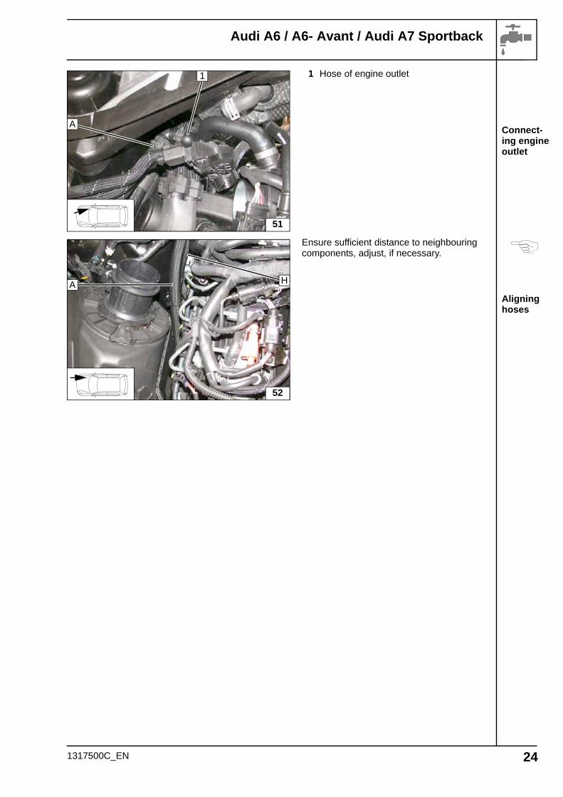
Connect-ing engine outlet
Aligning hoses
1 Hose of engine outlet
Ensure sufficient distance to neighbouring components, adjust, if necessary.
51
1
A
52
HA
1317500C_EN 24
Audi A6 / A6- Avant / Audi A7 Sportback
Connect-ing heater
Installing lines
Installing lines
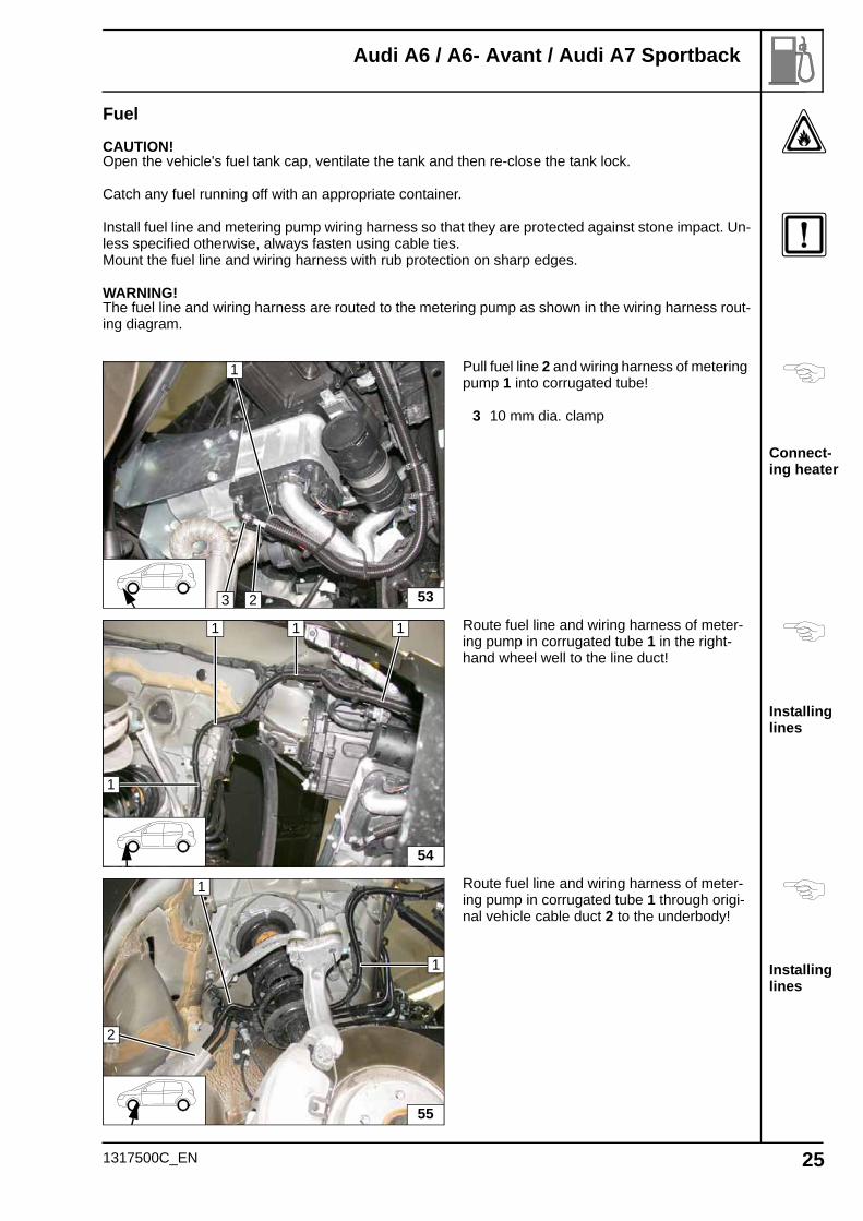
Fuel
CAUTION!Open the vehicle's fuel tank cap, ventilate the tank and then re-close the tank lock.
Catch any fuel running off with an appropriate container.
Install fuel line and metering pump wiring harness so that they are protected against stone impact. Un-less specified otherwise, always fasten using cable ties.Mount the fuel line and wiring harness with rub protection on sharp edges.
WARNING!The fuel line and wiring harness are routed to the metering pump as shown in the wiring harness rout-ing diagram.
Pull fuel line 2 and wiring harness of metering pump 1 into corrugated tube!
3 10 mm dia. clamp
Route fuel line and wiring harness of meter-ing pump in corrugated tube 1 in the right-hand wheel well to the line duct!
Route fuel line and wiring harness of meter-ing pump in corrugated tube 1 through origi-nal vehicle cable duct 2 to the underbody!
532
1
3
54
1 1 1
1
55
1
2
1
1317500C_EN 25
Audi A6 / A6- Avant / Audi A7 Sportback
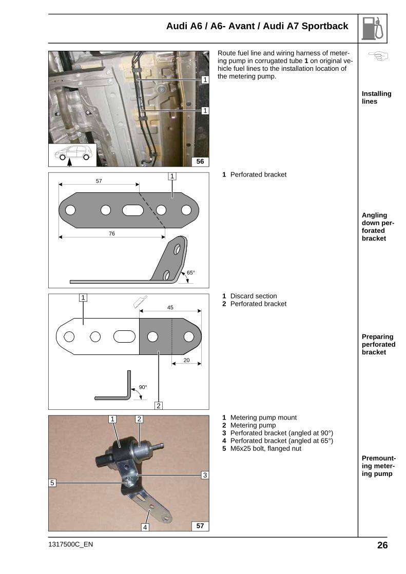
Installing lines
Angling down per-forated bracket
Preparing perforated bracket
Premount-ing meter-ing pump
Route fuel line and wiring harness of meter-ing pump in corrugated tube 1 on original ve-hicle fuel lines to the installation location of the metering pump.
1 Perforated bracket
1 Discard section2 Perforated bracket
1 Metering pump mount2 Metering pump3 Perforated bracket (angled at 90°)4 Perforated bracket (angled at 65°)5 M6x25 bolt, flanged nut
56
1
1
57
76
65°
1
45
90°
20
1
2
57
1 2
35
4
1317500C_EN 26
Audi A6 / A6- Avant / Audi A7 Sportback
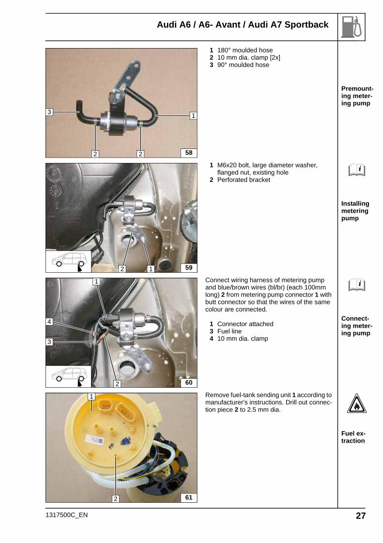
Premount-ing meter-ing pump
Installing metering pump
Connect-ing meter-ing pump
Fuel ex-traction
1 180° moulded hose2 10 mm dia. clamp [2x]3 90° moulded hose
1 M6x20 bolt, large diameter washer, flanged nut, existing hole
2 Perforated bracket
Connect wiring harness of metering pump and blue/brown wires (bl/br) (each 100mm long) 2 from metering pump connector 1 with butt connector so that the wires of the same colour are connected.
1 Connector attached3 Fuel line4 10 mm dia. clamp
Remove fuel-tank sending unit 1 according to manufacturer's instructions. Drill out connec-tion piece 2 to 2.5 mm dia.
58
13
22
592 1
60
1
3
4
2
61
1
2
1317500C_EN 27
Audi A6 / A6- Avant / Audi A7 Sportback
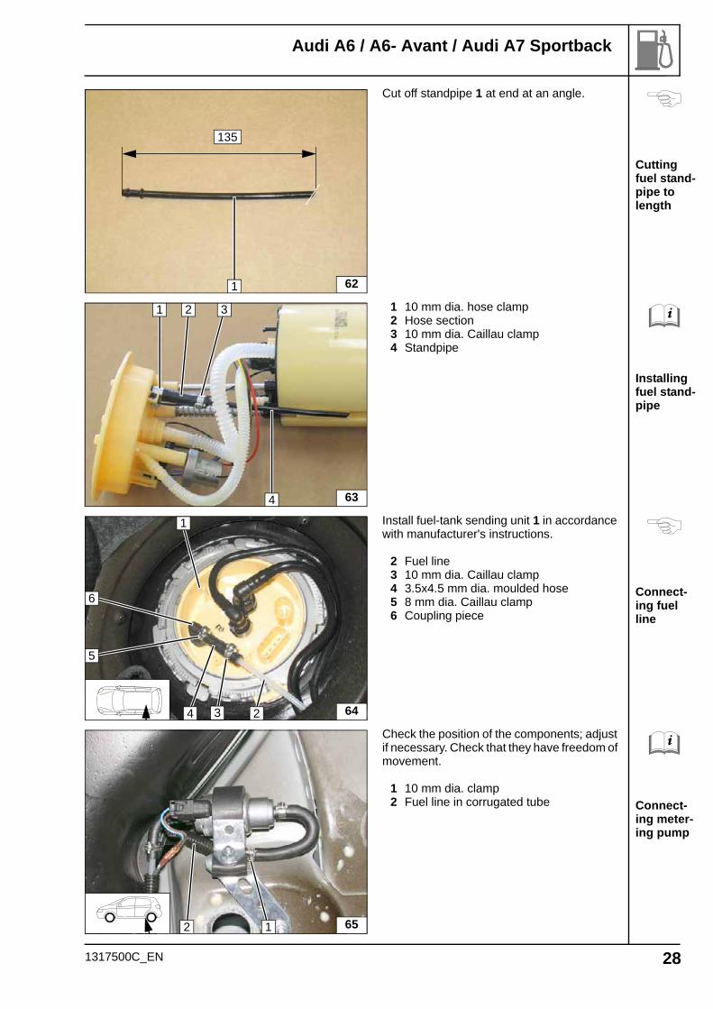
Cutting fuel stand-pipe to length
Installing fuel stand-pipe
Connect-ing fuel line
Connect-ing meter-ing pump
Cut off standpipe 1 at end at an angle.
1 10 mm dia. hose clamp2 Hose section3 10 mm dia. Caillau clamp4 Standpipe
Install fuel-tank sending unit 1 in accordance with manufacturer's instructions.
2 Fuel line3 10 mm dia. Caillau clamp4 3.5x4.5 mm dia. moulded hose5 8 mm dia. Caillau clamp6 Coupling piece
Check the position of the components; adjust if necessary. Check that they have freedom of movement.
1 10 mm dia. clamp2 Fuel line in corrugated tube
621
135
63
2
4
31
64
1
24
6
3
5
652 1
1317500C_EN 28
Audi A6 / A6- Avant / Audi A7 Sportback
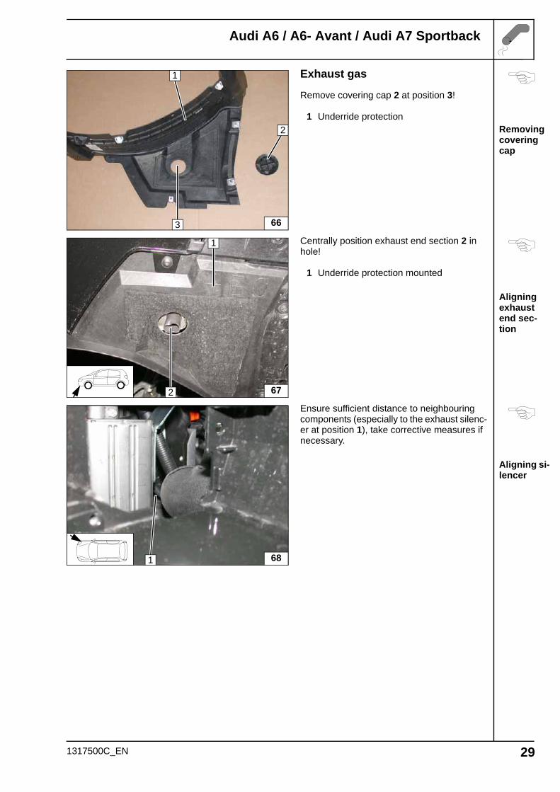
Removing covering cap
Aligning exhaust end sec-tion
Aligning si-lencer
Exhaust gas
Remove covering cap 2 at position 3!
1 Underride protection
Centrally position exhaust end section 2 in hole!
1 Underride protection mounted
Ensure sufficient distance to neighbouring components (especially to the exhaust silenc-er at position 1), take corrective measures if necessary.
66
2
1
3
2
1
67
1 68
1317500C_EN 29
Audi A6 / A6- Avant / Audi A7 Sportback
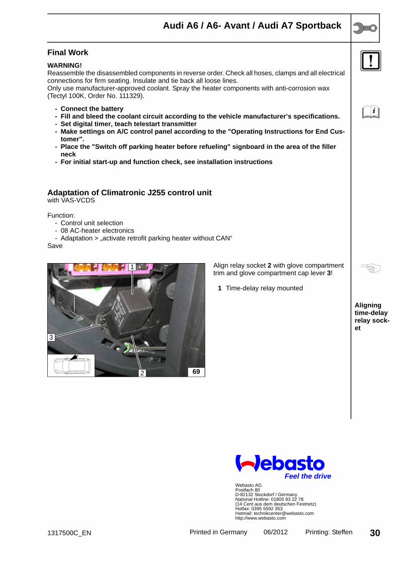
Aligning time-delay relay sock-et
Final Work
WARNING!Reassemble the disassembled components in reverse order. Check all hoses, clamps and all electrical connections for firm seating. Insulate and tie back all loose lines.Only use manufacturer-approved coolant. Spray the heater components with anti-corrosion wax (Tectyl 100K, Order No. 111329).
- Connect the battery- Fill and bleed the coolant circuit according to the vehicle manufacturer’s specifications.- Set digital timer, teach telestart transmitter- Make settings on A/C control panel according to the "Operating Instructions for End Cus-
tomer".- Place the "Switch off parking heater before refueling" signboard in the area of the filler
neck- For initial start-up and function check, see installation instructions
Adaptation of Climatronic J255 control unitwith VAS-VCDS
Function:- Control unit selection- 08 AC-heater electronics- Adaptation > „activate retrofit parking heater without CAN“
Save
Align relay socket 2 with glove compartment trim and glove compartment cap lever 3!
1 Time-delay relay mounted
69
1
2
3
Printed in Germany 06/2012 Printing: Steffen 301317500C_EN
Feel the driveWebasto AGPostfach 80D-82132 Stockdorf / GermanyNational Hotline: 01805 93 22 78(14 Cent aus dem deutschen Festnetz)Hotfax: 0395 5592 353Hotmail: [email protected]://www.webasto.com
Audi A6 / A6- Avant / Audi A7 Sportback
Climatron-ic
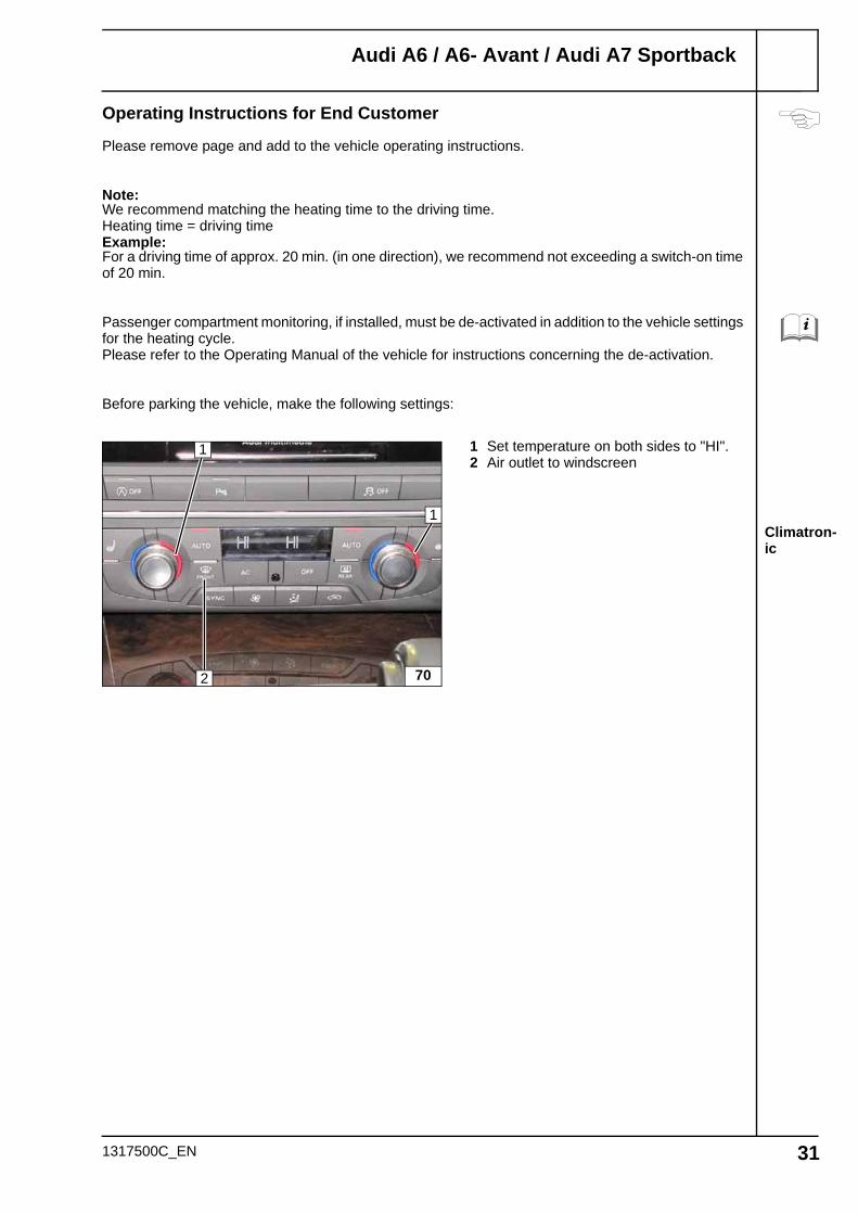
Operating Instructions for End Customer
Please remove page and add to the vehicle operating instructions.
Note:We recommend matching the heating time to the driving time.Heating time = driving timeExample:For a driving time of approx. 20 min. (in one direction), we recommend not exceeding a switch-on time of 20 min.
Passenger compartment monitoring, if installed, must be de-activated in addition to the vehicle settings for the heating cycle.Please refer to the Operating Manual of the vehicle for instructions concerning the de-activation.
Before parking the vehicle, make the following settings:
1 Set temperature on both sides to "HI".2 Air outlet to windscreen
70
1
2
1
1317500C_EN 31
Related Documents