Installation Devices Protective Solutions www.eaton.com Product Catalog 2019

Welcome message from author
This document is posted to help you gain knowledge. Please leave a comment to let me know what you think about it! Share it to your friends and learn new things together.
Transcript

Installation DevicesProtective Solutions
www.eaton.com
Product Catalog 2019

EATON CORPORATION xxxxx+xxxx-xxxxEN
1.1
1 EATON CORPORATION CA019011EN
Protective DevicesTable of Contents Protective Devices / Components
1. Protective Devices• Residual Current Devices PF7 . . . . . . . . . . . . . . . . . . . . . . . . . . . . . . . . . . . . . . . . . . . . . . . . . . . . . . . . . . . . . . . . . . . . . . . . . . . . . . Page 1.10• Residual Current Devices PF7-U . . . . . . . . . . . . . . . . . . . . . . . . . . . . . . . . . . . . . . . . . . . . . . . . . . . . . . . . . . . . . . . . . . . . . . . . . . . . Page 1.15• Residual Current Devices PFIM-F . . . . . . . . . . . . . . . . . . . . . . . . . . . . . . . . . . . . . . . . . . . . . . . . . . . . . . . . . . . . . . . . . . . . . . . . . . . Page 1.20• Residual Current Devices PF6 . . . . . . . . . . . . . . . . . . . . . . . . . . . . . . . . . . . . . . . . . . . . . . . . . . . . . . . . . . . . . . . . . . . . . . . . . . . . . . Page 1.25• Residual Current Devices HNC xPole Home . . . . . . . . . . . . . . . . . . . . . . . . . . . . . . . . . . . . . . . . . . . . . . . . . . . . . . . . . . . . . . . . . . Page 1.34• Residual Current Relays PFR, Core Balance Transformers Z-WFR. . . . . . . . . . . . . . . . . . . . . . . . . . . . . . . . . . . . . . . . . . . . . . . Page 1.39• Residual Current Devices PFDM . . . . . . . . . . . . . . . . . . . . . . . . . . . . . . . . . . . . . . . . . . . . . . . . . . . . . . . . . . . . . . . . . . . . . . . . . . . . Page 1.44• Residual Current Devices dRCM Digital. . . . . . . . . . . . . . . . . . . . . . . . . . . . . . . . . . . . . . . . . . . . . . . . . . . . . . . . . . . . . . . . . . . . . . Page 1.49• Add-on Residual Current Protection Unit PBHT. . . . . . . . . . . . . . . . . . . . . . . . . . . . . . . . . . . . . . . . . . . . . . . . . . . . . . . . . . . . . . . Page 1.54• Leakage Current Monitor PDIM . . . . . . . . . . . . . . . . . . . . . . . . . . . . . . . . . . . . . . . . . . . . . . . . . . . . . . . . . . . . . . . . . . . . . . . . . . . . Page 1.60• Arc Fault Detection Device AFDD+, 2-pole . . . . . . . . . . . . . . . . . . . . . . . . . . . . . . . . . . . . . . . . . . . . . . . . . . . . . . . . . . . . . . . . . . . Page 1.63• Combined RCD/MCB Devices PFL7, 1+N-pole . . . . . . . . . . . . . . . . . . . . . . . . . . . . . . . . . . . . . . . . . . . . . . . . . . . . . . . . . . . . . . . . Page 1.74• Combined RCD/MCB Devices PFL6, 1+N-pole . . . . . . . . . . . . . . . . . . . . . . . . . . . . . . . . . . . . . . . . . . . . . . . . . . . . . . . . . . . . . . . . Page 1.85• RCBO Devices HNB xPole Home. . . . . . . . . . . . . . . . . . . . . . . . . . . . . . . . . . . . . . . . . . . . . . . . . . . . . . . . . . . . . . . . . . . . . . . . . . . . Page 1.92• Combined RCD/MCB Devices mRB6, mRB4, 3+N-pole . . . . . . . . . . . . . . . . . . . . . . . . . . . . . . . . . . . . . . . . . . . . . . . . . . . . . . . . . Page 1.99• Miniature Circuit Breakers PL7 . . . . . . . . . . . . . . . . . . . . . . . . . . . . . . . . . . . . . . . . . . . . . . . . . . . . . . . . . . . . . . . . . . . . . . . . . . . . Page 1.105• Miniature Circuit Breakers PL6 . . . . . . . . . . . . . . . . . . . . . . . . . . . . . . . . . . . . . . . . . . . . . . . . . . . . . . . . . . . . . . . . . . . . . . . . . . . . Page 1.123• Miniature Circuit Breakers HL xPole Home . . . . . . . . . . . . . . . . . . . . . . . . . . . . . . . . . . . . . . . . . . . . . . . . . . . . . . . . . . . . . . . . . Page 1.140• Miniature Circuit Breakers PL7-DC for AC/DC . . . . . . . . . . . . . . . . . . . . . . . . . . . . . . . . . . . . . . . . . . . . . . . . . . . . . . . . . . . . . . . Page 1.148• Miniature Circuit Breakers with Plug-in Terminals at the output side PLI . . . . . . . . . . . . . . . . . . . . . . . . . . . . . . . . . . . . . . . Page 1.152• Miniature Circuit Breakers PLHT . . . . . . . . . . . . . . . . . . . . . . . . . . . . . . . . . . . . . . . . . . . . . . . . . . . . . . . . . . . . . . . . . . . . . . . . . . Page 1.158• Adjustable MCB Z-MS, Power Limiter Z-TS, Motor-protective Circuit-breaker. . . . . . . . . . . . . . . . . . . . . . . . . . . . . . . . . . . Page 1.171
SG17011
2. Accessories for Protective Devices• Auxiliary Switch Z-HK, Z-AHK, Z-HD; Tripping Signal Switch Z-NHK. . . . . . . . . . . . . . . . . . . . . . . . . . . . . . . . . . . . . . . . . . . . Page 2.180• Auxiliary Switch ZP-IHK, ZP-WHK; Tripping Signal Switch ZP-NHK . . . . . . . . . . . . . . . . . . . . . . . . . . . . . . . . . . . . . . . . . . . . Page 2.183• RCCB Tripping Module Z-.AM . . . . . . . . . . . . . . . . . . . . . . . . . . . . . . . . . . . . . . . . . . . . . . . . . . . . . . . . . . . . . . . . . . . . . . . . . . . . . Page 2.185• Shunt Trip Release Z-ASA, ZP-ASA . . . . . . . . . . . . . . . . . . . . . . . . . . . . . . . . . . . . . . . . . . . . . . . . . . . . . . . . . . . . . . . . . . . . . . . . Page 2.187• Undervoltage Release Z-USA, Z-USD . . . . . . . . . . . . . . . . . . . . . . . . . . . . . . . . . . . . . . . . . . . . . . . . . . . . . . . . . . . . . . . . . . . . . . Page 2.189• Switching Interlock IS/SPE-1TE, Z-IS/SPE-1TE . . . . . . . . . . . . . . . . . . . . . . . . . . . . . . . . . . . . . . . . . . . . . . . . . . . . . . . . . . . . . . Page 2.191• Terminal Covers Z-RC, Z-TC . . . . . . . . . . . . . . . . . . . . . . . . . . . . . . . . . . . . . . . . . . . . . . . . . . . . . . . . . . . . . . . . . . . . . . . . . . . . . . . Page 2.192• Remote Control and Automatic Switching Device Z-FW . . . . . . . . . . . . . . . . . . . . . . . . . . . . . . . . . . . . . . . . . . . . . . . . . . . . . . Page 2.193
SG30811
3. Surge Protection• Surge Protective Class T1/T2, SPRT12-350 . . . . . . . . . . . . . . . . . . . . . . . . . . . . . . . . . . . . . . . . . . . . . . . . . . . . . . . . . . . . . . . . . . Page 3.197• Surge Protective Class T1/T2 (formerly B+C), SPBT12 . . . . . . . . . . . . . . . . . . . . . . . . . . . . . . . . . . . . . . . . . . . . . . . . . . . . . . . . Page 3.201• Surge Protective Class T2 (formerly C), SPCT2 . . . . . . . . . . . . . . . . . . . . . . . . . . . . . . . . . . . . . . . . . . . . . . . . . . . . . . . . . . . . . . Page 3.205• Surge Protective Class T3 (formerly D), SPDT3 . . . . . . . . . . . . . . . . . . . . . . . . . . . . . . . . . . . . . . . . . . . . . . . . . . . . . . . . . . . . . . Page 3.212• Surge Protective Class T3 (formerly D), SPD-STL Multiple Outlet Strips . . . . . . . . . . . . . . . . . . . . . . . . . . . . . . . . . . . . . . . . Page 3.214• Surge Protective Class T3 (formerly D), Protection Strip Multiple Outlet Strips . . . . . . . . . . . . . . . . . . . . . . . . . . . . . . . . . . Page 3.214• Photovoltaic SPD Class T2, SPPVT2. . . . . . . . . . . . . . . . . . . . . . . . . . . . . . . . . . . . . . . . . . . . . . . . . . . . . . . . . . . . . . . . . . . . . . . . Page 3.215• Photovoltaic SPD Class T1/T2, SPPVT12 . . . . . . . . . . . . . . . . . . . . . . . . . . . . . . . . . . . . . . . . . . . . . . . . . . . . . . . . . . . . . . . . . . . . Page 3.218• Busbars for Surge Protection . . . . . . . . . . . . . . . . . . . . . . . . . . . . . . . . . . . . . . . . . . . . . . . . . . . . . . . . . . . . . . . . . . . . . . . . . . . . . Page 3.221
SG05013
1.2
2 EATON CORPORATION CA019011EN
Protective Devices
Table of Contents Protective Devices / Components
4. Controlling & Switching• Main Load Disconnector Switch (Isolator) IS. . . . . . . . . . . . . . . . . . . . . . . . . . . . . . . . . . . . . . . . . . . . . . . . . . . . . . . . . . . . . . . . Page 4.225• Circuit Breaker ZP-A . . . . . . . . . . . . . . . . . . . . . . . . . . . . . . . . . . . . . . . . . . . . . . . . . . . . . . . . . . . . . . . . . . . . . . . . . . . . . . . . . . . . . Page 4.227• MCB for Auxiliary Switch Circuits PL7-B4/.-HS . . . . . . . . . . . . . . . . . . . . . . . . . . . . . . . . . . . . . . . . . . . . . . . . . . . . . . . . . . . . . . Page 4.229• Pushbutton Z-T/; Control Switch Z-S../; Changeover Switch Z-S/.W . . . . . . . . . . . . . . . . . . . . . . . . . . . . . . . . . . . . . . . . . . . . Page 4.231• Switch Z-SW.; Signal Lamps Z-.EL, Z-.DL., Z-BEL; Pushbutton Z-PU.. . . . . . . . . . . . . . . . . . . . . . . . . . . . . . . . . . . . . . . . . . . . Page 4.233• Rotary Switch Z-DS . . . . . . . . . . . . . . . . . . . . . . . . . . . . . . . . . . . . . . . . . . . . . . . . . . . . . . . . . . . . . . . . . . . . . . . . . . . . . . . . . . . . . . Page 4.236• Installation Relays Z-R. . . . . . . . . . . . . . . . . . . . . . . . . . . . . . . . . . . . . . . . . . . . . . . . . . . . . . . . . . . . . . . . . . . . . . . . . . . . . . . . . . . . Page 4.242• Installation Relays Z-TN . . . . . . . . . . . . . . . . . . . . . . . . . . . . . . . . . . . . . . . . . . . . . . . . . . . . . . . . . . . . . . . . . . . . . . . . . . . . . . . . . . Page 4.247• Installation Contactors CR . . . . . . . . . . . . . . . . . . . . . . . . . . . . . . . . . . . . . . . . . . . . . . . . . . . . . . . . . . . . . . . . . . . . . . . . . . . . . . . . Page 4.252• Installation Contactors Z-SCH, CMUC . . . . . . . . . . . . . . . . . . . . . . . . . . . . . . . . . . . . . . . . . . . . . . . . . . . . . . . . . . . . . . . . . . . . . . Page 4.258• Impulse Relays Z-S, Z-SC, Z-SB . . . . . . . . . . . . . . . . . . . . . . . . . . . . . . . . . . . . . . . . . . . . . . . . . . . . . . . . . . . . . . . . . . . . . . . . . . . Page 4.268• Staircase Switch with switch-off warning and stop function TL . . . . . . . . . . . . . . . . . . . . . . . . . . . . . . . . . . . . . . . . . . . . . . . Page 4.278• Time-Lag Relay ZR . . . . . . . . . . . . . . . . . . . . . . . . . . . . . . . . . . . . . . . . . . . . . . . . . . . . . . . . . . . . . . . . . . . . . . . . . . . . . . . . . . . . . . . Page 4.280• Undervoltage Relay REUVM. . . . . . . . . . . . . . . . . . . . . . . . . . . . . . . . . . . . . . . . . . . . . . . . . . . . . . . . . . . . . . . . . . . . . . . . . . . . . . . Page 4.283• Voltage Indication UVA . . . . . . . . . . . . . . . . . . . . . . . . . . . . . . . . . . . . . . . . . . . . . . . . . . . . . . . . . . . . . . . . . . . . . . . . . . . . . . . . . . . Page 4.285• Load Shedding (Current) Relay Z-LAR . . . . . . . . . . . . . . . . . . . . . . . . . . . . . . . . . . . . . . . . . . . . . . . . . . . . . . . . . . . . . . . . . . . . . . Page 4.287• Digital Timers with a Weekly Program TSDW . . . . . . . . . . . . . . . . . . . . . . . . . . . . . . . . . . . . . . . . . . . . . . . . . . . . . . . . . . . . . . . Page 4.289• Astronomical Timer with a Weekly Program TSDW1COA . . . . . . . . . . . . . . . . . . . . . . . . . . . . . . . . . . . . . . . . . . . . . . . . . . . . . Page 4.293• Analogue Timers TS. . . . . . . . . . . . . . . . . . . . . . . . . . . . . . . . . . . . . . . . . . . . . . . . . . . . . . . . . . . . . . . . . . . . . . . . . . . . . . . . . . . . . . Page 4.294• Light Intensity Switch SR . . . . . . . . . . . . . . . . . . . . . . . . . . . . . . . . . . . . . . . . . . . . . . . . . . . . . . . . . . . . . . . . . . . . . . . . . . . . . . . . . Page 4.297• Signalling Devices AS . . . . . . . . . . . . . . . . . . . . . . . . . . . . . . . . . . . . . . . . . . . . . . . . . . . . . . . . . . . . . . . . . . . . . . . . . . . . . . . . . . . . Page 4.301• Bell-Transformers 230 V, TR-G . . . . . . . . . . . . . . . . . . . . . . . . . . . . . . . . . . . . . . . . . . . . . . . . . . . . . . . . . . . . . . . . . . . . . . . . . . . . . Page 4.303• Safety-Transformer 230 V, TR-G2/63-SF . . . . . . . . . . . . . . . . . . . . . . . . . . . . . . . . . . . . . . . . . . . . . . . . . . . . . . . . . . . . . . . . . . . . . Page 4.305
SG84011
5. Busbar Systems• Plug-in busbar System 50 A, 80 A ZV . . . . . . . . . . . . . . . . . . . . . . . . . . . . . . . . . . . . . . . . . . . . . . . . . . . . . . . . . . . . . . . . . . . . . . . Page 5.308• Busbar Block (Fork) Z-GV . . . . . . . . . . . . . . . . . . . . . . . . . . . . . . . . . . . . . . . . . . . . . . . . . . . . . . . . . . . . . . . . . . . . . . . . . . . . . . . . . Page 5.311• Busbar Block (Fork and Pin) Z-GSV . . . . . . . . . . . . . . . . . . . . . . . . . . . . . . . . . . . . . . . . . . . . . . . . . . . . . . . . . . . . . . . . . . . . . . . . Page 5.314• Busbar Block (Pin) Z-SV...-SD, 1 Meter . . . . . . . . . . . . . . . . . . . . . . . . . . . . . . . . . . . . . . . . . . . . . . . . . . . . . . . . . . . . . . . . . . . . . Page 5.316• Busbar Block (Pin) Z-SV . . . . . . . . . . . . . . . . . . . . . . . . . . . . . . . . . . . . . . . . . . . . . . . . . . . . . . . . . . . . . . . . . . . . . . . . . . . . . . . . . . Page 5.317• Busbar Block 12MU (Fork and Pin) Z-GSV-10. . . . . . . . . . . . . . . . . . . . . . . . . . . . . . . . . . . . . . . . . . . . . . . . . . . . . . . . . . . . . . . . Page 5.320• Busbar Block 13MU (Fork and Pin) Z-GSV-10. . . . . . . . . . . . . . . . . . . . . . . . . . . . . . . . . . . . . . . . . . . . . . . . . . . . . . . . . . . . . . . . Page 5.322• Busbar Block (Pin) Z-SV-../1P+N-F . . . . . . . . . . . . . . . . . . . . . . . . . . . . . . . . . . . . . . . . . . . . . . . . . . . . . . . . . . . . . . . . . . . . . . . . . Page 5.323• Busbar Block (Pin) Z-SV . . . . . . . . . . . . . . . . . . . . . . . . . . . . . . . . . . . . . . . . . . . . . . . . . . . . . . . . . . . . . . . . . . . . . . . . . . . . . . . . . . Page 5.325• Euro-Vario-Busbar (Fork) EVG . . . . . . . . . . . . . . . . . . . . . . . . . . . . . . . . . . . . . . . . . . . . . . . . . . . . . . . . . . . . . . . . . . . . . . . . . . . . . Page 5.328• Vertical Busbar BB-V-16/1P+N . . . . . . . . . . . . . . . . . . . . . . . . . . . . . . . . . . . . . . . . . . . . . . . . . . . . . . . . . . . . . . . . . . . . . . . . . . . . Page 5.331• AFDD-Busbar EVG-2PHAS/4AFDD . . . . . . . . . . . . . . . . . . . . . . . . . . . . . . . . . . . . . . . . . . . . . . . . . . . . . . . . . . . . . . . . . . . . . . . . . Page 5.332
SG50112
1.3
3 EATON CORPORATION CA019011EN
Protective DevicesTable of Contents Protective Devices / Components
7. Measuring Instruments• Power Meter EME . . . . . . . . . . . . . . . . . . . . . . . . . . . . . . . . . . . . . . . . . . . . . . . . . . . . . . . . . . . . . . . . . . . . . . . . . . . . . . . . . . . . . . . Page 7.449• Multimeter EME3PMMCT5 . . . . . . . . . . . . . . . . . . . . . . . . . . . . . . . . . . . . . . . . . . . . . . . . . . . . . . . . . . . . . . . . . . . . . . . . . . . . . . . . Page 7.463• LAN Server Modbus/TCP EMELSMODBUS. . . . . . . . . . . . . . . . . . . . . . . . . . . . . . . . . . . . . . . . . . . . . . . . . . . . . . . . . . . . . . . . . . Page 7.465• Ammeter and Voltmeter Digital EM, Current Transformer Z-MG . . . . . . . . . . . . . . . . . . . . . . . . . . . . . . . . . . . . . . . . . . . . . . . Page 7.467• Operating Hours Counter ASOHC230 . . . . . . . . . . . . . . . . . . . . . . . . . . . . . . . . . . . . . . . . . . . . . . . . . . . . . . . . . . . . . . . . . . . . . . . Page 7.472• Pulse Counter ASPC230 . . . . . . . . . . . . . . . . . . . . . . . . . . . . . . . . . . . . . . . . . . . . . . . . . . . . . . . . . . . . . . . . . . . . . . . . . . . . . . . . . . Page 7.472
wa_sg05811
8. Other Accessories• Protective Earth Socket Z-SD230 . . . . . . . . . . . . . . . . . . . . . . . . . . . . . . . . . . . . . . . . . . . . . . . . . . . . . . . . . . . . . . . . . . . . . . . . . . Page 8.474• Neutral Conductor Lead-Through Terminal, Feed Terminal Z-D . . . . . . . . . . . . . . . . . . . . . . . . . . . . . . . . . . . . . . . . . . . . . . . . Page 8.475• Front Plate Tripping Device Z-MFPA. . . . . . . . . . . . . . . . . . . . . . . . . . . . . . . . . . . . . . . . . . . . . . . . . . . . . . . . . . . . . . . . . . . . . . . . Page 8.476• Circuit Description GR, Plastic Box Z-BOX . . . . . . . . . . . . . . . . . . . . . . . . . . . . . . . . . . . . . . . . . . . . . . . . . . . . . . . . . . . . . . . . . . Page 8.477
sg68912
6. Fuse Devices (Protective Devices)• Fuse-Base D01+D02 FCFBD02DI . . . . . . . . . . . . . . . . . . . . . . . . . . . . . . . . . . . . . . . . . . . . . . . . . . . . . . . . . . . . . . . . . . . . . . . . . . . . . . . . 6.334• Switch-Disconnector-Fuse D01 Z-SLS/D01 . . . . . . . . . . . . . . . . . . . . . . . . . . . . . . . . . . . . . . . . . . . . . . . . . . . . . . . . . . . . . . . . . . . . . . . 6.336• Fuse-Switch-Disconnector D02+D01 Z-SLS/NEOZ . . . . . . . . . . . . . . . . . . . . . . . . . . . . . . . . . . . . . . . . . . . . . . . . . . . . . . . . . . . . . . . . 6.338• Fuse-Switch-Disconnector D02+D01 Z-SLS/CEK . . . . . . . . . . . . . . . . . . . . . . . . . . . . . . . . . . . . . . . . . . . . . . . . . . . . . . . . . . . . . . . . . . 6.341• Fuse-Switch-Disconnector D02+D01 Z-SLK/NEOZ . . . . . . . . . . . . . . . . . . . . . . . . . . . . . . . . . . . . . . . . . . . . . . . . . . . . . . . . . . . . . . . . 6.343• Fuse-Switch-Disconnector D02+D01 Z-SLS/B, Z-SLS/E . . . . . . . . . . . . . . . . . . . . . . . . . . . . . . . . . . . . . . . . . . . . . . . . . . . . . . . . . . . . 6.346• Fuse-Switch-Disconnector D02+D01 Z-SLS/CB . . . . . . . . . . . . . . . . . . . . . . . . . . . . . . . . . . . . . . . . . . . . . . . . . . . . . . . . . . . . . . . . . . . 6.350• Switch-Disconnector-Fuse D02+D01 D02-LTS . . . . . . . . . . . . . . . . . . . . . . . . . . . . . . . . . . . . . . . . . . . . . . . . . . . . . . . . . . . . . . . . . . . . 6.353• Fuse-Disconnector (empty) Z-SH, Z-SI . . . . . . . . . . . . . . . . . . . . . . . . . . . . . . . . . . . . . . . . . . . . . . . . . . . . . . . . . . . . . . . . . . . . . . . . . . 6.355• Fuse-Switch-Disconnector (empty) C10-SLS, VLCE. . . . . . . . . . . . . . . . . . . . . . . . . . . . . . . . . . . . . . . . . . . . . . . . . . . . . . . . . . . . . . . . 6.360• Fuse-Disconnector (empty) CHPV… (old FCFDC10DI-..-SOL) . . . . . . . . . . . . . . . . . . . . . . . . . . . . . . . . . . . . . . . . . . . . . . . . . . . . . . . 6.363• Slide Fuse Equipment, 3-pole D02-SO/63/3-R-27, Z-D02/R/3… . . . . . . . . . . . . . . . . . . . . . . . . . . . . . . . . . . . . . . . . . . . . . . . . . . . . . . 6.366• Slide Fuse Equipment, 3-pole DII-SO/25/3-R(-PS), DIII-SO/63/3-R(-PS) . . . . . . . . . . . . . . . . . . . . . . . . . . . . . . . . . . . . . . . . . . . . . . 6.366• Slide Fuse Equipment, 3-pole FCFBD02BBC60 . . . . . . . . . . . . . . . . . . . . . . . . . . . . . . . . . . . . . . . . . . . . . . . . . . . . . . . . . . . . . . . . . . . . 6.366• Slide Fuse Equipment, 3-pole D02-S/63/3-RS . . . . . . . . . . . . . . . . . . . . . . . . . . . . . . . . . . . . . . . . . . . . . . . . . . . . . . . . . . . . . . . . . . . . . 6.367• Slide Fuse Equipment, 3-pole D02-LTS/63/3-R(-HK) . . . . . . . . . . . . . . . . . . . . . . . . . . . . . . . . . . . . . . . . . . . . . . . . . . . . . . . . . . . . . . . . 6.368• Fuse-Links Z-D0./SE, Operating class gG (gL) Z-D0./SE . . . . . . . . . . . . . . . . . . . . . . . . . . . . . . . . . . . . . . . . . . . . . . . . . . . . . . . . . . . . 6.373• Cartridge-Ring Adapter Insert Z-D0./PE, Z-D02-D01/PE . . . . . . . . . . . . . . . . . . . . . . . . . . . . . . . . . . . . . . . . . . . . . . . . . . . . . . . . . . . . 6.374• Screw Caps, Adapter Spring, Cartridge-Ring Adapter Insert Plier Z-D0./SK . . . . . . . . . . . . . . . . . . . . . . . . . . . . . . . . . . . . . . . . . . 6.375• Fuse-Links Z-DII./SE. . . . . . . . . . . . . . . . . . . . . . . . . . . . . . . . . . . . . . . . . . . . . . . . . . . . . . . . . . . . . . . . . . . . . . . . . . . . . . . . . . . . . . . . . . . 6.376• Gauge Ring Z-DII./PE, Screw-in Gauge Ring Z-DII./PS. . . . . . . . . . . . . . . . . . . . . . . . . . . . . . . . . . . . . . . . . . . . . . . . . . . . . . . . . . . . . 6.378• Screw Caps CD, Z-DII./SK . . . . . . . . . . . . . . . . . . . . . . . . . . . . . . . . . . . . . . . . . . . . . . . . . . . . . . . . . . . . . . . . . . . . . . . . . . . . . . . . . . . . . 6.379• Fuse-Links C..G.., (old Z-C../SE) Operating class gG (gL). . . . . . . . . . . . . . . . . . . . . . . . . . . . . . . . . . . . . . . . . . . . . . . . . . . . . . . . . . . . 6.380• Fuse-Links PV-..A10F (old ASFLC10-..A-gPV-SOL) Photovoltaic Application. . . . . . . . . . . . . . . . . . . . . . . . . . . . . . . . . . . . . . . . . . . 6.384• Solid-Links Z-NH-../TR . . . . . . . . . . . . . . . . . . . . . . . . . . . . . . . . . . . . . . . . . . . . . . . . . . . . . . . . . . . . . . . . . . . . . . . . . . . . . . . . . . . . . . . . . 6.386• NH-Fuse-Links, 500 V AC, …NHG…B (old Z-NH) . . . . . . . . . . . . . . . . . . . . . . . . . . . . . . . . . . . . . . . . . . . . . . . . . . . . . . . . . . . . . . . . . 6.387• Fuse Switch Disconnectors XNH . . . . . . . . . . . . . . . . . . . . . . . . . . . . . . . . . . . . . . . . . . . . . . . . . . . . . . . . . . . . . . . . . . . . . . . . . . . . . . . 6.390• NH In-line Fuse Switch Disconnectors, series FCFSDNH . . . . . . . . . . . . . . . . . . . . . . . . . . . . . . . . . . . . . . . . . . . . . . . . . . . . . . . . . . 6.421• NH In-line Fuse Switch Disconnectors, series NH-SLS and NHW-SLS . . . . . . . . . . . . . . . . . . . . . . . . . . . . . . . . . . . . . . . . . . . . . . 6.432• NH-Vertical Fuse-Switch-Disconnector, 3-pole LTS-L . . . . . . . . . . . . . . . . . . . . . . . . . . . . . . . . . . . . . . . . . . . . . . . . . . . . . . . . . . . . . 6.446
SG80911
1.4
4 EATON CORPORATION CA019011EN
Protective Devices
General
Residual Current Devices - General Data
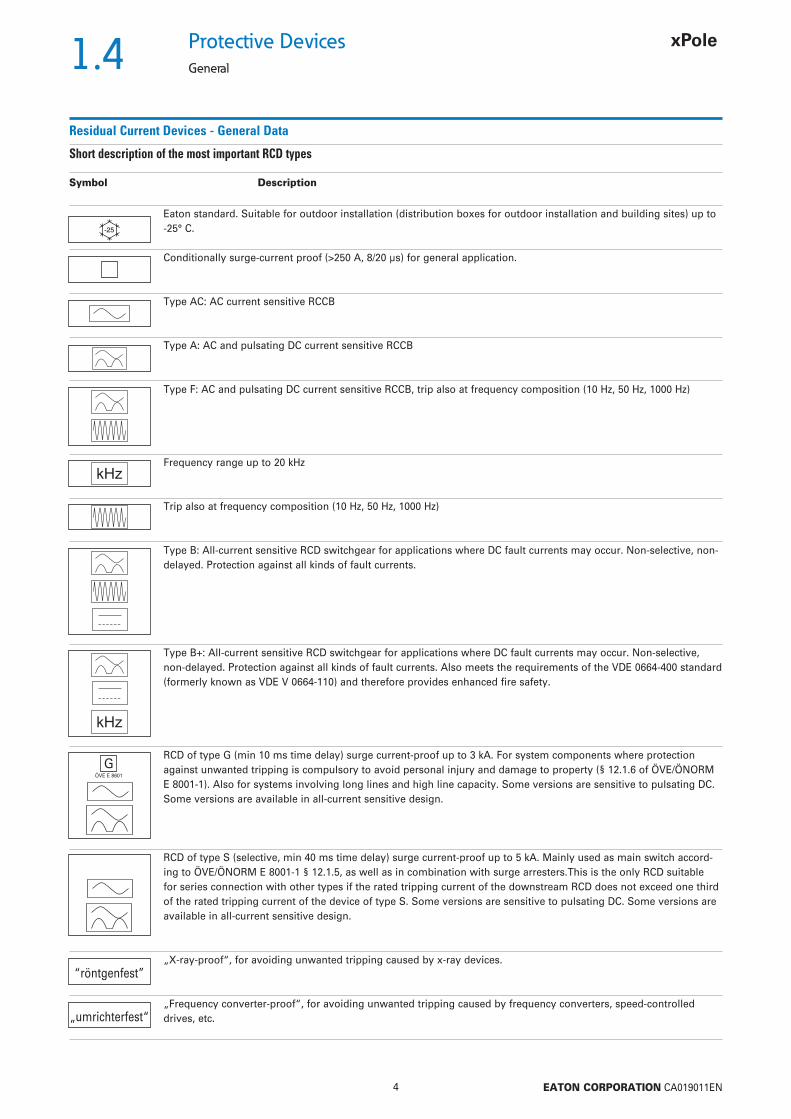
Short description of the most important RCD types
Symbol Description
Eaton standard. Suitable for outdoor installation (distribution boxes for outdoor installation and building sites) up to
-25° C.
Conditionally surge-current proof (>250 A, 8/20 µs) for general application.
Type AC: AC current sensitive RCCB
Type A: AC and pulsating DC current sensitive RCCB
Type F: AC and pulsating DC current sensitive RCCB, trip also at frequency composition (10 Hz, 50 Hz, 1000 Hz)
Frequency range up to 20 kHz
Trip also at frequency composition (10 Hz, 50 Hz, 1000 Hz)
Type B: All-current sensitive RCD switchgear for applications where DC fault currents may occur. Non-selective, non-delayed. Protection against all kinds of fault currents.
Type B+: All-current sensitive RCD switchgear for applications where DC fault currents may occur. Non-selective, non-delayed. Protection against all kinds of fault currents. Also meets the requirements of the VDE 0664-400 standard (formerly known as VDE V 0664-110) and therefore provides enhanced fi re safety.
RCD of type G (min 10 ms time delay) surge current-proof up to 3 kA. For system components where protection against unwanted tripping is compulsory to avoid personal injury and damage to property (§ 12.1.6 of ÖVE/ÖNORM E 8001-1). Also for systems involving long lines and high line capacity. Some versions are sensitive to pulsating DC. Some versions are available in all-current sensitive design.
RCD of type S (selective, min 40 ms time delay) surge current-proof up to 5 kA. Mainly used as main switch accord-ing to ÖVE/ÖNORM E 8001-1 § 12.1.5, as well as in combination with surge arresters.This is the only RCD suitable for series connection with other types if the rated tripping current of the downstream RCD does not exceed one third of the rated tripping current of the device of type S. Some versions are sensitive to pulsating DC. Some versions are available in all-current sensitive design.
„X-ray-proof“, for avoiding unwanted tripping caused by x-ray devices.
„Frequency converter-proof“, for avoiding unwanted tripping caused by frequency converters, speed-controlled drives, etc.
„umrichterfest“
S
GÖVE E 8601
“röntgenfest”
1.5
5 EATON CORPORATION CA019011EN
Protective DevicesGeneral
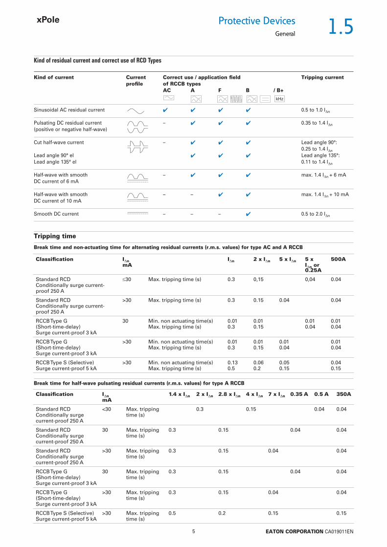
Kind of residual current and correct use of RCD Types
Kind of current Current Correct use / application fi eld Tripping current profi le of RCCB types AC A F B / B+
Sinusoidal AC residual current 0.5 to 1.0 In
Pulsating DC residual current – 0.35 to 1.4 In (positive or negative half-wave)
Cut half-wave current – Lead angle 90°: 0.25 to 1.4 In Lead angle 90° el Lead angle 135°:Lead angle 135° el 0.11 to 1.4 In
Half-wave with smooth – max. 1.4 In + 6 mADC current of 6 mA
Half-wave with smooth – – max. 1.4 In + 10 mADC current of 10 mA
Smooth DC current – – – 0.5 to 2.0 In
Tripping time
Break time and non-actuating time for alternating residual currents (r.m.s. values) for type AC and A RCCB
Classifi cation InmA
In 2 x In 5 x In 5 x In or 0.25A
500A
Standard RCD Conditionally surge current-proof 250 A
30 Max. tripping time (s) 0.3 0,15 0,04 0.04
Standard RCDConditionally surge current-proof 250 A
>30 Max. tripping time (s) 0.3 0.15 0.04 0.04
RCCB Type G(Short-time-delay)Surge current-proof 3 kA
30 Min. non actuating time(s)Max. tripping time (s)
0.010.3
0.010.15
0.010.04
0.010.04
RCCB Type G (Short-time-delay)Surge current-proof 3 kA
>30 Min. non actuating time(s)Max. tripping time (s)
0.010.3
0.010.15
0.010.04
0.010.04
RCCB Type S (Selective)Surge current-proof 5 kA
>30 Min. non actuating time(s)Max. tripping time (s)
0.130.5
0.060.2
0.050.15
0.040.15
Break time for half-wave pulsating residual currents (r.m.s. values) for type A RCCB
Classifi cation InmA
1.4 x In 2 x In 2.8 x In 4 x In 7 x In 0.35 A 0.5 A 350A
Standard RCD Conditionally surge current-proof 250 A
<30 Max. tripping time (s)
0.3 0.15 0.04 0.04
Standard RCD Conditionally surge current-proof 250 A
30 Max. tripping time (s)
0.3 0.15 0.04 0.04
Standard RCDConditionally surge current-proof 250 A
>30 Max. tripping time (s)
0.3 0.15 0.04 0.04
RCCB Type G(Short-time-delay)Surge current-proof 3 kA
30 Max. tripping time (s)
0.3 0.15 0.04 0.04
RCCB Type G (Short-time-delay)Surge current-proof 3 kA
>30 Max. tripping time (s)
0.3 0.15 0.04 0.04
RCCB Type S (Selective)Surge current-proof 5 kA
>30 Max. tripping time (s)
0.5 0.2 0.15 0.15

1.6
6 EATON CORPORATION CA019011EN
Protective Devices
General
Tripping Characteristics (IEC/EN 61008)
§ 6.1.1 of ÖVE/ÖNORM E 8001-1/A1 deals with additional protection and provides essentially the following: In circuits with sockets up to 16 A with fault current/residual current protection by protective earthing, protective multiple earth-ing or residual current devices (RCDs), additional residual current protection devices with a rated tripping current of 0.03 A must be installed.This means when using RCDs for fault current/residual cur-rent protection two RCDs must be connected in series.
Testing:RCDs with tripping time delay (Types -G and -S) may be function tested with conventional testing equipment which must be set according to the instructions for operation of the testing device. Due to reasons inherent in the measuring process, the tripping time determined in this way may be longer than expected in accord-ance with the specifi cations of the manufacturer of the measuring instrument. However, the device is ok if the result of measurement is within the time range specifi ed by the manufacturer of the measuring instrument.
Tripping characteristics, tripping time range and selectivity of instan-taneous, surge current-proof „G“ and surge current-proof - selective „S“ residual current devices.
Trip
ping
tim
e t
Tripping time range type S
Residual tripping current
surge current.-proof - selective
surge current-proof
conditionally surge current-proof
Tripping time range type G
Tripping time range limit values
Tripping time range non-delayed
Area of unwanted tripping

1.7
7 EATON CORPORATION CA019011EN
Protective DevicesGeneral
Hints for the application of our frequency converter-proof RCDs:
Frequency converters are used in a wide variety of systems and equipment requiring variable speed, such as lifts, escalators, con-veyor belts, and large washing machines. Using them for such pur-poses in circuits with conventional residual current devices causes frequent problems with unwanted tripping.
The technical root cause of this phenomenon is the following: Fast switching operations involving high voltages cause high interfer-ence levels which propagate through the lines on the one hand, and in the form of interfering radiation on the other. In order to eliminate this problem, a mains-side fi lter (also referred to as input fi lter or EMC-fi lter) is connected between the RCD and frequency converter. The anti-interference capacitors in the fi lters produce discharge currents against earth which may cause unwanted trip-ping of the RCD due to the apparent residual currents. Connecting a fi lter on the output side between frequency converter and 3-phase AC motor results in the same behaviour.
Due to the currents fl owing off through the fi lters (designated IF), the sum of currents through the RCD is not exactly zero, which causes unwanted tripping.
This sample tripping characteristic of a 100 mA RCD and a 300 mA RCD shows the following: In the frequency range around 50 Hz, the RCDs trip as required (50 - 100 % of the indicated In).In the range shown hatched in the diagram, i. e. from approx. 100 to 300 Hz, unwanted tripping occurs frequently due to the use of frequency converters. Frequency converter-proof residual current devices are much less sensitive in this frequency range than in the 50 - 60 Hz range, which leads to an enormous increase in the reli-ability of systems.
Therefore, we recommend to use frequency converter-proof RCDs!These special residual current devices can be recognised by an exten-sion of the type designation („-U“). They meet the requirements of compatibility between RCDs and frequency converters with respect to unwanted tripping.
These are NOT AC/DC-sensitive RCDs of type B !!!
Our RCDs of type „-U“ are characterised by SENSITIVITY TO RESIDUAL PULSATING DC and SELECTIVITY or SHORT-TIME DELAY GS
Tripping characteristic
Protective Measures
In Austria, the ÖVE Decision EN 219 is applicable.
Under this standard
• frequency converters must be equipped with current limiting devices in order to ensure disconnection in cause of faults or overload, and
• the installer of a system is obliged to make sure that additional equipotential bonding is provided (additional inclusion of all metal components, such as frequency converters, mains fi lters, motor fi lters, etc. into the existing equipotential bonding), in order to ensure that the permissible touch voltage of 50 V AC or 120 V DC is
not exceeded. (In ÖVE/ÖNORM E 8001-1 the term „touch voltage“ has been omitted. There is only a fault voltage limit of 65 V AC or 120 V DC which must not be exceeded).
In Germany, VDE 0100 is applicable, in Switzerland SEV 1000.
In case of application in any other country than those mentioned take into account national rules and recommendations.
The following rules for the application of RCDs of type“ -U“ are only applicable in those cases where an RCD of type „-B“ is not explicitly demanded in the instructions of the manufacturer of the frequency converter.
How can you make sure that the required protective measures are in place when using RCDs type “-U” and frequency converters in one system?
Mains
RC
DR
CD
Mai
ns-s
ide
fi lte
rM
ains
-sid
e fi l
ter
Freq
uenc
y co
nver
ter
Freq
uenc
y co
nver
ter
Scr
eene
d m
otor
line
Mai
ns s
ide
fi lte
r
Mot
orM
otor
Frequency converter interference range (approx. 100 - 300 Hz)

1.8
8 EATON CORPORATION CA019011EN
Protective Devices
General
Numerous advantages at a glance
• The difference between harmless and critical fault currents is detected
• Precise switching and reduction of nuisance tripping
• Continuous monitoring of plant/factory status – prompt warning of a change in status quo
• Convenient troubleshooting by precise location of the malfunction
• As easy to install as a conventional RCCB
• Longer intervals between servicing
• Ideal for system monitoring thanks to preventive information
• Warning of tripping at leakage current
• Clear status display of the fault cur- rent problem with tri-colored LEDs
• Real contact position indicator
• Indicator for fault current tripping
• Comprehensive range of accessories available
• Can be integrated in several bus systems
Digital protection switches –
the new era has begun.
Better security with proactive communication!The digital RCCB from Eaton’s xEffect series are capable to do more than just switch off: They monitor electrical instal-lations and issue advance warnings of critical current fl ows. Thanks to short time delay and optimized tripping thresh-old, briefl y occurring malfunctions do not induce the digital protection switch to shut down.
When a fault current crops up, the information is reported to the security center of the industrial plant right away and troubleshooting can start before a plant failure occurs. Thus the cause of the fault current can be determined precisely and the system can be serviced easily.
That way, system availability increases and service is crucially improved by the convenient remote control.
1.9
9 EATON CORPORATION CA019011EN
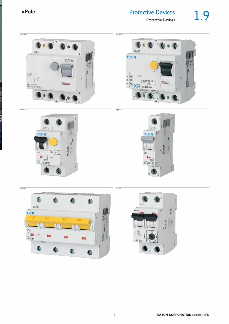
Protective DevicesProtective Devices
sg01018_r SG08310
SG04414 Sg04312
sg44811 SG09911
1.10
10 EATON CORPORATION CA019011EN
Protective Devices
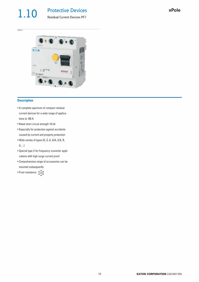
Residual Current Devices PF7
• A complete spectrum of compact residual
current devices for a wide range of applica-
tions to 100 A
• Rated short circuit strength 10 kA
• Especially for protection against accidents
caused by current and property protection
• Wide variety of types (G, S, A, G/A, S/A, R,
U, ...)
• Special type U for frequency converter appli-
cations with high surge current proof
• Comprehensive range of accessories can be
mounted subsequently
• Frost resistance
Description
SG08211

1.11
11 EATON CORPORATION CA019011EN
Protective DevicesResidual Current Devices PF7
Type AC
Conditionally surge current-proof 250 A, type ACSG07411
25/0.03 PF7-25/2/003 263577 1/6025/0.10 PF7-25/2/01 263578 1/6040/0.03 PF7-40/2/003 263579 1/6040/0.10 PF7-40/2/01 263580 1/6063/0.03 PF7-63/2/003 263581 1/6063/0.10 PF7-63/2/01 263582 1/6063/0.30 PF7-63/2/03 263583 1/60100/0.03 PF7-100/2/003 166797 1/60100/0.10 PF7-100/2/01 166799 1/60100/0.30 PF7-100/2/03 166822 1/60
In/In
(A)TypeDesignation
Article No. Units perpackage
2-pole
SG08211
25/0.03 PF7-25/4/003 263584 1/3025/0.10 PF7-25/4/01 263585 1/3040/0.03 PF7-40/4/003 263586 1/3040/0.10 PF7-40/4/01 263587 1/3040/0.30 PF7-40/4/03 263588 1/3040/0.50 PF7-40/4/05 263589 1/3063/0.03 PF7-63/4/003 263590 1/3063/0.10 PF7-63/4/01 263591 1/3063/0.30 PF7-63/4/03 263592 1/3063/0.50 PF7-63/4/05 263593 1/3080/0.03 PF7-80/4/003 263594 1/3080/0.10 PF7-80/4/01 263595 1/3080/0.30 PF7-80/4/03 263596 1/3080/0.50 PF7-80/4/05 263597 1/30100/0.03 PF7-100/4/003 102925 1/30100/0.10 PF7-100/4/01 102926 1/30100/0.30 PF7-100/4/03 102927 1/30100/0.50 PF7-100/4/05 102928 1/30
4-pole
1.12
12 EATON CORPORATION CA019011EN
Protective Devices
Residual Current Devices PF7
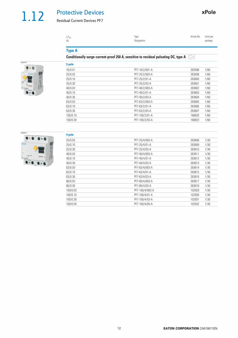
Type A
Conditionally surge current-proof 250 A, sensitive to residual pulsating DC, type ASG07411
16/0.01 PF7-16/2/001-A 263598 1/6025/0.03 PF7-25/2/003-A 263599 1/6025/0.10 PF7-25/2/01-A 263600 1/6025/0.30 PF7-25/2/03-A 263601 1/6040/0.03 PF7-40/2/003-A 263602 1/6040/0.10 PF7-40/2/01-A 263603 1/6040/0.30 PF7-40/2/03-A 263604 1/6063/0.03 PF7-63/2/003-A 263605 1/6063/0.10 PF7-63/2/01-A 263606 1/6063/0.30 PF7-63/2/03-A 263607 1/60100/0.10 PF7-100/2/01-A 166820 1/60100/0.30 PF7-100/2/03-A 166823 1/60
In/In
(A)TypeDesignation
Article No. Units perpackage
2-pole
SG08211
25/0.03 PF7-25/4/003-A 263608 1/3025/0.10 PF7-25/4/01-A 263609 1/3025/0.30 PF7-25/4/03-A 263610 1/3040/0.03 PF7-40/4/003-A 263611 1/3040/0.10 PF7-40/4/01-A 263612 1/3040/0.30 PF7-40/4/03-A 263613 1/3063/0.03 PF7-63/4/003-A 263614 1/3063/0.10 PF7-63/4/01-A 263615 1/3063/0.30 PF7-63/4/03-A 263616 1/3080/0.03 PF7-80/4/003-A 263617 1/3080/0.30 PF7-80/4/03-A 263618 1/30100/0.03 PF7-100/4/003-A 102929 1/30100/0.10 PF7-100/4/01-A 102930 1/30100/0.30 PF7-100/4/03-A 102931 1/30100/0.50 PF7-100/4/05-A 102932 1/30
4-pole

1.13
13 EATON CORPORATION CA019011EN
Protective DevicesResidual Current Devices PF7
Type G, type G/A
Surge current-proof 3 kA, type G (ÖVE E 8601), type G , type G/ASG07411
25/0.03 PF7-25/2/003-G 263619 1/6025/0.10 PF7-25/2/01-G 263620 1/6040/0.03 PF7-40/2/003-G 263621 1/6040/0.10 PF7-40/2/01-G 263622 1/6040/0.03 PF7-40/2/003-G/A 166826 1/6063/0.03 PF7-63/2/003-G/A 166827 1/6080/0.03 PF7-80/2/003-G/A 166828 1/60100/0.03 PF7-100/2/003-G/A 166798 1/60
In/In
(A)TypeDesignation
Article No. Units perpackage
2-pole
SG08211
40/0.03 PF7-40/4/003-G 263623 1/3040/0.10 PF7-40/4/01-G 263624 1/3063/0.03 PF7-63/4/003-G 263625 1/3063/0.10 PF7-63/4/01-G 263627 1/3080/0.03 PF7-80/4/003-G/A 166824 1/30100/0.03 PF7-100/4/003-G/A 166829 1/30100/0.3 PF7-100/4/03-G/A 166825 1/30
4-pole
Type R
Surge current-proof 3 kA, X-ray application, type RSG08211
63/0.03 PF7-63/4/003-R 263628 1/30100/0.03 PF7-100/4/003-R 102935 1/30
4-pole
Type S
Selective + surge current-proof 5 kA, type SSG07411
40/0.10 PF7-40/2/01-S 263629 1/6040/0.30 PF7-40/2/03-S 263630 1/60
2-pole
SG08211
80/0.10 PF7-80/4/01-S 263636 1/30
4-pole
1.14
14 EATON CORPORATION CA019011EN
Protective Devices
Residual Current Devices PF7
Type S/A
Selective + surge current-proof 5 kA, sensitive to residual pulsating DC, type S/A
In/In
(A)TypeDesignation
Article No. Units perpackage
SG08211
25/0.10 PF7-25/4/01-S/A 263631 1/3040/0.10 PF7-40/4/01-S/A 263632 1/3040/0.30 PF7-40/4/03-S/A 263633 1/3063/0.10 PF7-63/4/01-S/A 263634 1/3063/0.30 PF7-63/4/03-S/A 263635 1/3080/0.30 PF7-80/4/03-S/A 263637 1/30100/0.30 PF7-100/4/03-S/A 292494 1/30
4-pole

1.15
15 EATON CORPORATION CA019011EN
Protective DevicesResidual Current Devices PF7-U
• Special residual current devices
– for frequency converter applications
• For fault current/residual current protection
and additional protection
• Comprehensive range of accessories can be
mounted subsequently
• Real contact position indicator
• Selective
• Frost resistance
Description
SG08211

1.16
16 EATON CORPORATION CA019011EN
Protective Devices
Residual Current Devices PF7-U
Type U
Selective + surge current-proof 5 kA, frequency converter-proof, type U
In/In
(A)TypeDesignation
Article No. Units perpackage
SG08211
40/0.10 PF7-40/4/01-U 263638 1/3040/0.30 PF7-40/4/03-U 263639 1/3063/0.10 PF7-63/4/01-U 263640 1/3063/0.30 PF7-63/4/03-U 263641 1/3080/0.30 PF7-80/4/03-U 292495 1/30100/0.30 PF7-100/4/03-U 292496 1/30
4-pole
Sealing Cover Set Z-RC/AK
Type TypeDesignation
Article No. Units perpackage
SG82011 2-pole Z-RC/AK-2TE 285385 10/304-pole Z-RC/AK-4MU 101062 10/600
• for PFIM, PFR, PF6, PF7, CFI6, dRCM (not to use for PFDM)

1.17
17 EATON CORPORATION CA019011EN
Protective DevicesResidual Current Devices PF7-U - Technical Data
Specifi cations | Residual Current Devices PF7
Description
• Residual Current Devices• Shape compatible with and suitable for standard busbar connection to other
devices of the P-series• Twin-purpose terminal (lift/open-mouthed) above and below• Busbar positioning optionally above or below• Free terminal space despite installed busbar• Universal tripping signal switch, also suitable for PL., PFL., Z-A. can be
mounted subsequently• Auxiliary switch Z-HK can be mounted subsequently• Contact position indicator red - green• Delayed types suitable for being used with standard fl uorescent tubes with
or without electronical ballast (30mA-RCD: 30 units per phase conductor, 100mA-RCD: 90 units per phase conductor).Notes: Depending of the fl uorescent lamp ballast manufacturer partly more possible. Symmetrical allocation of the fl uorescent lamp ballasts on all phases favourably. Shifting references of the fl uorescent lamp ballast manu-facturer consider.
• The device functions irrespective of the position of installation• Tripping is line voltage-independent. Consequently, the RCD is suitable for
“fault current/residual current protection” and “additional protection” within the the meaning of the applicable installation rules
• Mains connection at either side• Types with 80 and 100 A permissible short-circuit back-up fuse (PF7-80, PF7-
100): Take into account overload protection• The 4-pole device can also be used for 2- or 3-pole connection. See connec-
tion possibilities.• The test key “T” must be pressed every 6 month. The system operator must
be informed of this obligation and his responsibility in a way that can be proven (self-adhesive RCD-label enclosed). The test intervall of 6 month is valid for residential and similar applications. Under all other conditions (e.g. damply or dusty environments), it’s recommended to test in shorter intervalls (e.g. monthly).
• Pressing the test key “T” serves the only purpose of function testing the residual current device (RCD). This test does not make earthing resistance measurement (RE), or proper checking of the earth conductor condition redundant, which must be performed separately.
• Type -A: Protects against special forms of residual pulsating DC which have have not been smoothed
• Type -G: High reliability against unwanted tripping. Compulsory for any circuit where personal injury or damage to property may occur in case of unwanted tripping (ÖVE/ÖNORM E 8001-1 § 12.1.6)
• Type -G/A: Additionally protects against special forms of residual pulsating DC which have not been smoothed Special types for X-ray application PF7-...-R
• Type -S: Selective residual current device sensitive to AC, type -S.Compulsory for systems with surge arresters downstream of the RCD (ÖVE/ÖNORM E 8001-1 § 12.1.5).
• Type -S/A: Additionally protects against special forms of residual pulsating DC which have not been smoothed
Accessories:Auxiliary switch for subsequent installation to the left Z-HK 248432Tripping signal contact for subsequent installation to the right Z-NHK 248434Remote control and automatic switching device Z-FW/LP 248296Compact enclosure KLV-TC-2 276240
KLV-TC-4 276241Sealing cover set Z-RC/AK-2TE 285385
Z-RC/AK-4MU 101062

1.18
18 EATON CORPORATION CA019011EN
Protective Devices
Residual Current Devices PF7-U - Technical Data
Technical DataPF7
ElectricalDesign according to
Current test marks as printed onto the device
IEC/EN 61008Type G according to ÖVE E 8601
Tripping instantaneousType G 10 ms delayType S 40 ms delay - selective disconnecting function
Rated voltage Un 230/400 V AC, 50 HzRated tripping current In 10, 30, 100, 300, 500 mASensitivity AC and pulsating DCRated insulation voltage Ui 440 VRated impulse withstand voltage Uimp 4 kV (1.2/50 μs)Rated short circuit strength Icn 10 kAMaximum back-up fuse Short circuit Overload
In = 16 A 63 A gG/gL 10 A gG/gLIn = 25 A 63 A gG/gL 16 A gG/gLIn = 40 A 63 A gG/gL 25 A gG/gLIn = 63 A 63 A gG/gL 40 A gG/gLIn = 80 A 80 A gG/gL 50 A gG/gLIn = 100 A 100 A gG/gL 63 A gG/g
In the case that the maximal possible operating current of the electrical installation don´t exceed the rated current of the RCD only short circuit protection must be implemented. Overload protection must be implemented in the case if the maximal possible operating current of the electrical installation can exceed the rated current of the RCD.
Rated breaking capacity ImRated fault breaking capacity Im
In = 16-40 A 500 AIn = 63 A 630 AIn = 80 A 800 AIn = 100 A 1000 A
Voltage range of test button2-pole 196 - 264 V~4-pole 30 mA 196 - 264 V~4-pole 10, 100, 300, 500 mA 196 - 456 V~
Enduranceelectrical components 4,000 switching operationsmechanical components 20,000 switching operations
MechanicalFrame size 45 mmDevice height 80 mmDevice width 35 mm (2MU), 70 mm (4MU)Mounting quick fastening with 2 lock-in positions on DIN rail IEC/EN 60715Degree of protection, built-in IP40Degree of protection in moisture-proof enclosure IP54Upper and lower terminals open mouthed/lift terminalsTerminal protection fi nger and hand touch safe, DGUV VS3, EN 50274Terminal capacity 1x (1.5 - 35) mm2 single wire
2x (1.5 - 16) mm2 multi wireBusbar thickness 0.8 - 2 mmTripping temperature -25°C to +40°CStorage- and transport temperature -35°C to +60°CResistance to climatic conditions 25-55°C/90-95% relative humidity according to IEC 60068-2
Connection diagrams2-pole 4-pole

1.19
19 EATON CORPORATION CA019011EN
Protective DevicesResidual Current Devices PF7-U - Technical Data
Dimensions (mm)
35
4580
10,5
4,530,5
44
60
5,52P
70
80
4P
Correct connection
30mA types:
10, 100, 300, 500mA types:
4-pole
30, 100, 300, 500mA types:
2-pole(230V AC)
2-pole
2-pole(230V AC)
3+N(230/400V AC)
3-phase application without N(230V AC phase-phase)
3-phase load without N(400V AC phase-phase)
3-phase application without N(400V AC phase-phase)
load
mains
2-pole(230V AC)
3+N(230/400V AC)
3-phase application without N(230/400V AC phase-phase)
3-phase load without N(400V AC phase-phase)
load
mains
Not allowed
Infl uence of the ambient temperature to the maximum continuous current (A)
16A 25A 40A 63A 80A 100AAmbient temperature 2p 2p 4p 2p 4p 2p 4p 4p 4p40° 16 25 25 40 40 63 63 80 10045° 14 21 22 37 37 59 59 76 9550° 11 18 19 33 34 55 55 72 9055° 9 14 16 30 31 50 50 68 8560° – *) –*) –*) 26 27 45 45 64 80
Annotation: It has to be ensured that the values in the table are not exceeded and the back-up fuse/thermal protection works properly.
*) not applicable

1.20
20 EATON CORPORATION CA019011EN
Protective Devices
Residual Current Devices PFIM-F
wa_sg02716
• Increased protection in applications with
1phase frequency converter due to the detec-
tion of mixed frequencies
• Reduction of nuisance tripping thanks to
- time delayed tripping
- increased current withstand capability > 3 kA
• Higher load rating with DC residual currents
up to 10 mA
• For fault current/residual current protection
and additional protection
• Comprehensive range of accessories
• Real contact position indicator
• Automatic re-setting possible
Description
1.21
21 EATON CORPORATION CA019011EN
Protective DevicesResidual Current Devices PFIM-F
Type G/F
Surge current-proof 3 kA, sensitive to residual pulsating DC, type G/F (ÖVE E 8601)wa_sg02816
25/0.03 PFIM-25/2/003-G/F 187449 1/6025/0.30 PFIM-25/2/03-G/F 187452 1/6040/0.03 PFIM-40/2/003-G/F 187450 1/6040/0.30 PFIM-40/2/03-G/F 187453 1/6063/0.03 PFIM-63/2/003-G/F 187451 1/6063/0.30 PFIM-63/2/03-G/F 187454 1/60
In/In
(A)TypeDesignation
Article No. Units perpackage
2-pole
wa_sg02716
25/0.03 PFIM-25/4/003-G/F 187455 1/3025/0.30 PFIM-25/4/03-G/F 187359 1/3040/0.03 PFIM-40/4/003-G/F 187456 1/3040/0.30 PFIM-40/4/03-G/F 187360 1/3063/0.03 PFIM-63/4/003-G/F 187358 1/3063/0.30 PFIM-63/4/03-G/F 187361 1/30
4-pole
Type S/F
Selective + surge current-proof 5 kA, sensitive to residual pulsating DC, type S/Fwa_sg02716
25/0.30 PFIM-25/4/03-S/F 187362 1/3040/0.30 PFIM-40/4/03-S/F 187363 1/3063/0.30 PFIM-63/4/03-S/F 187364 1/30
4-pole
Explanation PFIM: P = xPole, FI = Residual Current Devices, M = 10 kA
1.22
22 EATON CORPORATION CA019011EN
Protective Devices
Residual Current Devices PFIM-F - Technical Data
Specifi cations | Residual Current Devices PFIM-F
Description
• Residual Current Devices• Shape compatible with and suitable for standard busbar connection to other
devices of the P-series• Twin-purpose terminal (lift/open-mouthed) above and below• Busbar positioning optionally above or below• Free terminal space despite installed busbar• Universal tripping signal switch, also suitable for PLS., PKN., Z-A. can be
mounted subsequently• Auxiliary switch Z-HK can be mounted subsequently• Contact position indicator red - green• Delayed types suitable for being used with standard fl uorescent tubes with
or without electronical ballast (30mA-RCD: 30 units per phase conductor).Notes: Depending of the fl uorescent lamp ballast manufacturer partly more possible. Symmetrical allocation of the fl uorescent lamp ballasts on all phases favourably. Shifting references of the fl uorescent lamp ballast manu-facturer consider.
• The device functions irrespective of the position of installation• Tripping is line voltage-independent. Consequently, the RCD is suitable for
“fault current/residual current protection” and “additional protection” within the the meaning of the applicable installation rules
• Mains connection at either side• The 4-pole device can also be used for 2- or 3-pole connection. See connec-
tion possibilities.• The test key “T” must be pressed every 6 month. The system operator must
be informed of this obligation and his responsibility in a way that can be proven (self-adhesive RCD-label enclosed). The test intervall of 6 month is valid for residential and similar applications. Under all other conditions (e.g. damply or dusty environments), it’s recommended to test in shorter intervalls (e.g. monthly).
• Pressing the test key “T” serves the only purpose of function testing the residual current device (RCD). This test does not make earthing resistance measurement (RE), or proper checking of the earth conductor condition redundant, which must be performed separately.
• Type -F: Increased protection in applications with 1phase frequency con-verter due to the detection of mixed frequencies, higher load capacity with smooth DC fault currents up to 10 mA.
Accessories:Auxiliary switch for subsequent installation to the left Z-HK 248432Tripping signal contact for subsequent installation to the right Z-NHK 248434Remote control and automatic switching device Z-FW/LP 248296Compact enclosure KLV-TC-2 276240
KLV-TC-4 276241Sealing cover set Z-RC/AK-2TE 285385
Z-RC/AK-4MU 101062
1.23
23 EATON CORPORATION CA019011EN
Protective DevicesResidual Current Devices PFIM-F - Technical Data
Technical DataPFIM-F
ElectricalDesign according to
Current test marks as printed onto the device
IEC/EN 62423Type G according to ÖVE E 8601
Tripping instantaneousType G 10 ms delayType S 40 ms delay - selective disconnecting function
Rated voltage Un 230/400 V AC, 50 HzRated tripping current In 30, 300 mASensitivity AC and pulsating DCRated insulation voltage Ui 440 VRated impulse withstand voltage Uimp 4 kV (1.2/50 μs)Rated short circuit strength Icn 10 kAMaximum back-up fuse Short circuit Overload
In = 25 A 63 A gG/gL 16 A gG/gLIn = 40 A 63 A gG/gL 25 A gG/gLIn = 63 A 63 A gG/gL 40 A gG/gL
In the case that the maximal possible operating current of the electrical installation don´t exceed the rated current of the RCD only short circuit protection must be implemented. Overload protection must be implemented in the case if the maximal possible operating current of the electrical installation can exceed the rated current of the RCD.
Rated breaking capacity ImRated fault breaking capacity Im
In = 16-40 A 500 AIn = 63 A 630 A
Voltage range of test button2-pole 196 - 264 V~4-pole 30 mA 196 - 264 V~4-pole 300 mA 196 - 456 V~
Enduranceelectrical components 4,000 switching operationsmechanical components 20,000 switching operations
MechanicalFrame size 45 mmDevice height 80 mmDevice width 35 mm (2MU), 70 mm (4MU)Mounting quick fastening with 2 lock-in positions on DIN rail IEC/EN 60715Degree of protection, built-in IP40Degree of protection in moisture-proof enclosure IP54Upper and lower terminals open mouthed/lift terminalsTerminal protection fi nger and hand touch safe, DGUV VS3, EN 50274Terminal capacity 1.5 - 35 mm2 single wire
2 x 16 mm2 multi wireTerminal screw M5 (mit geschlitzter Schraube according to EN ISO 4757-Z2, Pozidriv PZ2)Terminal torque 2 - 2.4 NmBusbar thickness 0.8 - 2 mmTripping temperature -25°C to +40°CStorage- and transport temperature -35°C to +60°CResistance to climatic conditions 25-55°C/90-95% relative humidity according to IEC 60068-2
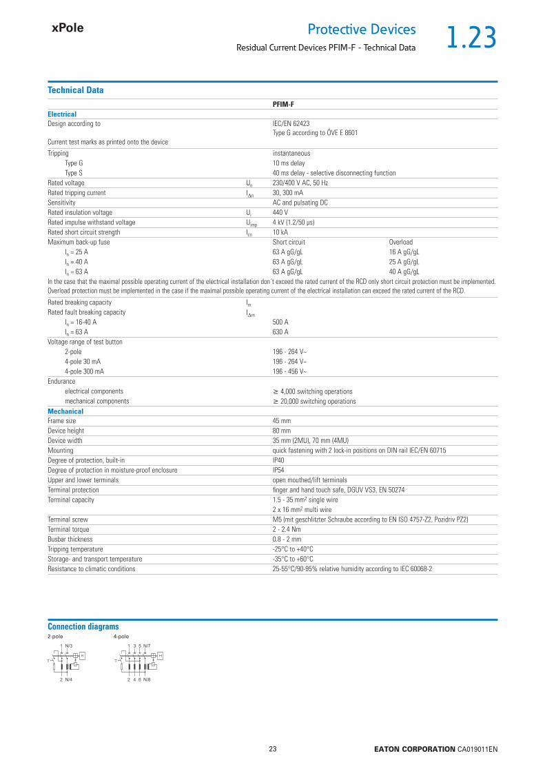
Connection diagrams2-pole 4-pole
1.24
24 EATON CORPORATION CA019011EN
Protective Devices
Residual Current Devices PFIM-F - Technical Data
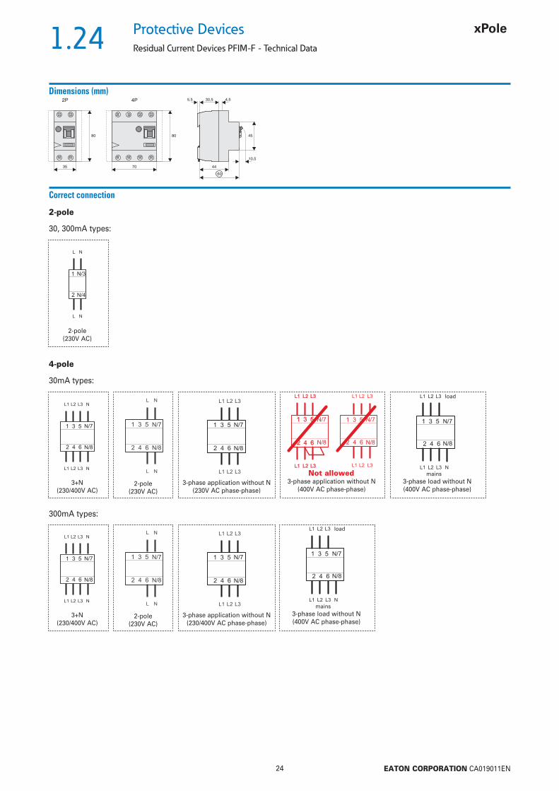
Dimensions (mm)
35
4580
10,5
4,530,5
44
60
5,52P
70
80
4P
Correct connection
30mA types:
300mA types:
4-pole
30, 300mA types:
2-pole(230V AC)
2-pole
2-pole(230V AC)
3+N(230/400V AC)
3-phase application without N(230V AC phase-phase)
3-phase load without N(400V AC phase-phase)
3-phase application without N(400V AC phase-phase)
load
mains
2-pole(230V AC)
3+N(230/400V AC)
3-phase application without N(230/400V AC phase-phase)
3-phase load without N(400V AC phase-phase)
load
mains
Not allowed
1.25
25 EATON CORPORATION CA019011EN
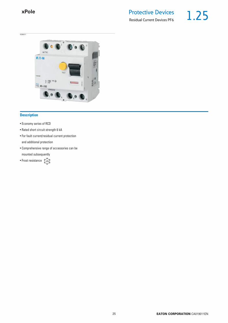
Protective DevicesResidual Current Devices PF6
• Economy series of RCD
• Rated short circuit strength 6 kA
• For fault current/residual current protection
and additional protection
• Comprehensive range of accessories can be
mounted subsequently
• Frost resistance
Description
SG80011

1.26
26 EATON CORPORATION CA019011EN
Protective Devices
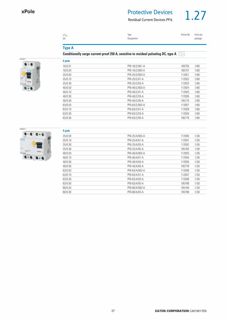
Residual Current Devices PF6
Type AC
Conditionally surge current-proof 250 A, type ACSG79411
16/0.01 PF6-16/2/001 165756 1/6016/0.03 PF6-16/2/003 119429 1/6025/0.03 PF6-25/2/003 286492 1/6025/0.10 PF6-25/2/01 286493 1/6025/0.30 PF6-25/2/03 286494 1/6025/0.50 PF6-25/2/05 286495 1/6040/0.03 PF6-40/2/003 286496 1/6040/0.10 PF6-40/2/01 286497 1/6040/0.30 PF6-40/2/03 286498 1/6040/0.50 PF6-40/2/05 286499 1/6063/0.03 PF6-63/2/003 286500 1/6063/0.10 PF6-63/2/01 286501 1/6063/0.30 PF6-63/2/03 286502 1/6063/0.50 PF6-63/2/05 286503 1/6080/0.03 PF6-80/2/003 165790 1/6080/0.10 PF6-80/2/01 165791 1/6080/0.30 PF6-80/2/03 165792 1/6080/0.50 PF6-80/2/05 165793 1/60
In/In
(A)TypeDesignation
Article No. Units perpackage
2-pole
SG80011
25/0.03 PF6-25/4/003 286504 1/3025/0.10 PF6-25/4/01 286505 1/3025/0.30 PF6-25/4/03 286506 1/3025/0.50 PF6-25/4/05 286507 1/3040/0.03 PF6-40/4/003 286508 1/3040/0.10 PF6-40/4/01 286509 1/3040/0.30 PF6-40/4/03 286510 1/3040/0.50 PF6-40/4/05 286511 1/3063/0.03 PF6-63/4/003 286512 1/3063/0.10 PF6-63/4/01 286513 1/3063/0.30 PF6-63/4/03 286514 1/3063/0.50 PF6-63/4/05 286515 1/3080/0.03 PF6-80/4/003 165795 1/3080/0.10 PF6-80/4/01 165796 1/3080/0.30 PF6-80/4/03 165799 1/3080/0.50 PF6-80/4/05 165802 1/30
4-pole
1.27
27 EATON CORPORATION CA019011EN
Protective DevicesResidual Current Devices PF6
Type A
Conditionally surge current-proof 250 A, sensitive to residual pulsating DC, type ASG79411
16/0.01 PF6-16/2/001-A 165755 1/6016/0.03 PF6-16/2/003-A 165757 1/6025/0.03 PF6-25/2/003-A 112921 1/6025/0.10 PF6-25/2/01-A 112922 1/6025/0.30 PF6-25/2/03-A 112923 1/6040/0.03 PF6-40/2/003-A 112924 1/6040/0.10 PF6-40/2/01-A 112925 1/6040/0.30 PF6-40/2/03-A 112926 1/6040/0.50 PF6-40/2/05-A 165770 1/6063/0.03 PF6-63/2/003-A 112927 1/6063/0.10 PF6-63/2/01-A 112928 1/6063/0.30 PF6-63/2/03-A 112929 1/6063/0.50 PF6-63/2/05-A 165779 1/60
In/In
(A)TypeDesignation
Article No. Units perpackage
2-pole
SG80011
25/0.03 PF6-25/4/003-A 112930 1/3025/0.10 PF6-25/4/01-A 112931 1/3025/0.30 PF6-25/4/03-A 112932 1/3025/0.50 PF6-25/4/05-A 165763 1/3040/0.03 PF6-40/4/003-A 112933 1/3040/0.10 PF6-40/4/01-A 112934 1/3040/0.30 PF6-40/4/03-A 112935 1/3040/0.50 PF6-40/4/05-A 165778 1/3063/0.03 PF6-63/4/003-A 112936 1/3063/0.10 PF6-63/4/01-A 112937 1/3063/0.30 PF6-63/4/03-A 112938 1/3063/0.50 PF6-63/4/05-A 165789 1/3080/0.03 PF6-80/4/003-A 165794 1/3080/0.30 PF6-80/4/03-A 165798 1/30
4-pole
1.28
28 EATON CORPORATION CA019011EN
Protective Devices
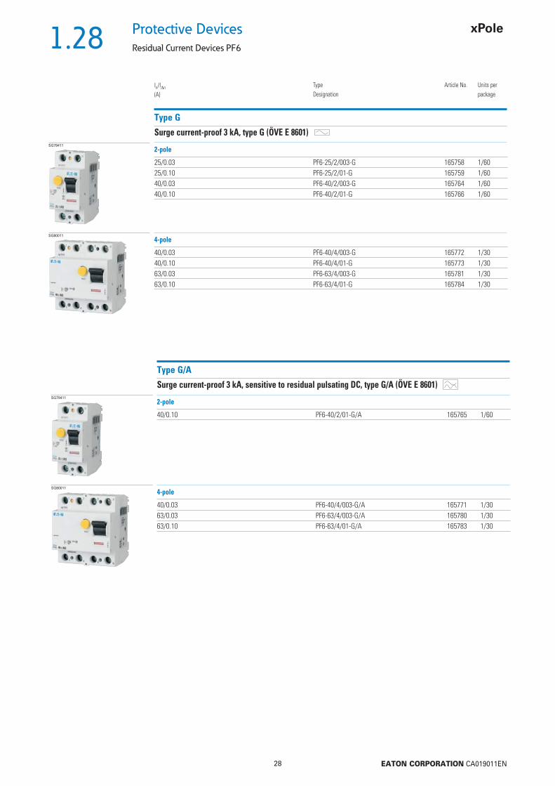
Residual Current Devices PF6
Type G
Surge current-proof 3 kA, type G (ÖVE E 8601)SG79411
25/0.03 PF6-25/2/003-G 165758 1/6025/0.10 PF6-25/2/01-G 165759 1/6040/0.03 PF6-40/2/003-G 165764 1/6040/0.10 PF6-40/2/01-G 165766 1/60
In/In
(A)TypeDesignation
Article No. Units perpackage
2-pole
SG80011
40/0.03 PF6-40/4/003-G 165772 1/3040/0.10 PF6-40/4/01-G 165773 1/3063/0.03 PF6-63/4/003-G 165781 1/3063/0.10 PF6-63/4/01-G 165784 1/30
4-pole
Type G/A
Surge current-proof 3 kA, sensitive to residual pulsating DC, type G/A (ÖVE E 8601)SG79411
40/0.10 PF6-40/2/01-G/A 165765 1/60
2-pole
SG80011
40/0.03 PF6-40/4/003-G/A 165771 1/3063/0.03 PF6-63/4/003-G/A 165780 1/3063/0.10 PF6-63/4/01-G/A 165783 1/30
4-pole
1.29
29 EATON CORPORATION CA019011EN
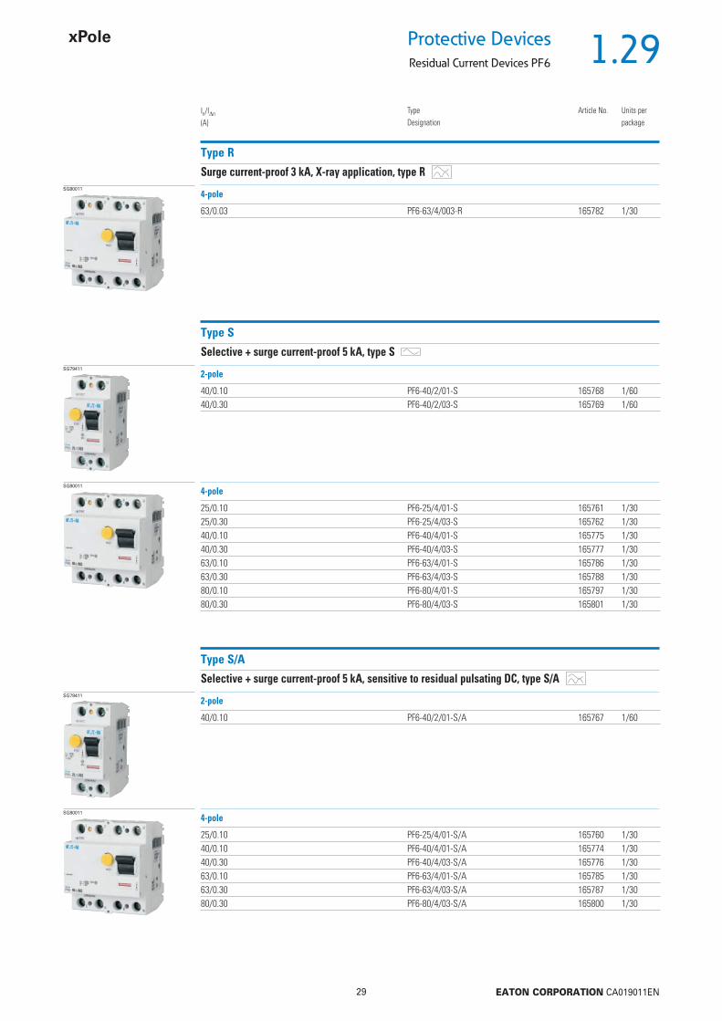
Protective DevicesResidual Current Devices PF6
Type R
Surge current-proof 3 kA, X-ray application, type R
In/In
(A)TypeDesignation
Article No. Units perpackage
SG80011
63/0.03 PF6-63/4/003-R 165782 1/30
4-pole
Type S
Selective + surge current-proof 5 kA, type SSG79411
40/0.10 PF6-40/2/01-S 165768 1/6040/0.30 PF6-40/2/03-S 165769 1/60
2-pole
SG80011
25/0.10 PF6-25/4/01-S 165761 1/3025/0.30 PF6-25/4/03-S 165762 1/3040/0.10 PF6-40/4/01-S 165775 1/3040/0.30 PF6-40/4/03-S 165777 1/3063/0.10 PF6-63/4/01-S 165786 1/3063/0.30 PF6-63/4/03-S 165788 1/3080/0.10 PF6-80/4/01-S 165797 1/3080/0.30 PF6-80/4/03-S 165801 1/30
4-pole
Type S/A
Selective + surge current-proof 5 kA, sensitive to residual pulsating DC, type S/ASG79411
40/0.10 PF6-40/2/01-S/A 165767 1/60
2-pole
SG80011
25/0.10 PF6-25/4/01-S/A 165760 1/3040/0.10 PF6-40/4/01-S/A 165774 1/3040/0.30 PF6-40/4/03-S/A 165776 1/3063/0.10 PF6-63/4/01-S/A 165785 1/3063/0.30 PF6-63/4/03-S/A 165787 1/3080/0.30 PF6-80/4/03-S/A 165800 1/30
4-pole

1.30
30 EATON CORPORATION CA019011EN
Protective Devices
Residual Current Devices PF6
Sealing Cover Set Z-RC/AK
Type TypeDesignation
Article No. Units perpackage
SG82011 2-pole Z-RC/AK-2TE 285385 10/304-pole Z-RC/AK-4MU 101062 10/600
• for PFIM, PFR, PF6, PF7, CFI6, dRCM (not to use for PFDM)

1.31
31 EATON CORPORATION CA019011EN
Protective DevicesResidual Current Devices PF6 - Technical Data
Specifi cations | Residual Current Devices PF6
Description
• Twin-purpose terminal (lift/open-mouthed) above and below• Busbar positioning optionally above or below• Free terminal space despite installed busbar• Universal tripping signal switch, also suitable for PLS., PKN., Z-A. can be
mounted subsequently• Auxiliary switch Z-HK can be mounted subsequently• Contact position indicator red - green• Delayed types suitable for being used with standard fl uorescent tubes with
or without electronical ballast (30mA-RCD: 30 units per phase conductor, 100mA-RCD: 90 units per phase conductor).Notes: Depending of the fl uorescent lamp ballast manufacturer partly more possible. Symmetrical allocation of the fl uorescent lamp ballasts on all phases favourably. Shifting references of the fl uorescent lamp ballast manu-facturer consider.
• The device functions irrespective of the position of installation• Tripping is line voltage-independent. Consequently, the RCD is suitable for
“fault current/residual current protection” and “additional protection” within the the meaning of the applicable installation rules
• Mains connection at either side• The 4-pole device can also be used for 2- or 3-pole connection. See connec-
tion possibilities.• The test key “T” must be pressed every 6 month. The system operator must
be informed of this obligation and his responsibility in a way that can be proven (self-adhesive RCD-label enclosed). The test intervall of 6 month is valid for residential and similar applications. Under all other conditions (e.g. damply or dusty environments), it’s recommended to test in shorter intervalls (e.g. monthly).
• Pressing the test key “T” serves the only purpose of function testing the residual current device (RCD). This test does not make earthing resistance measurement (RE), or proper checking of the earth conductor condition redundant, which must be performed separately.
• Type -A: Protects against special forms of residual pulsating DC which have have not been smoothed
• Type -G: High reliability against unwanted tripping. Compulsory for any circuit where personal injury or damage to property may occur in case of unwanted tripping (ÖVE/ÖNORM E 8001-1 § 12.1.6)
• Type -G/A: Additionally protects against special forms of residual pulsating DC which have not been smoothed. Special types for X-ray application PFIM-...-R
• Type -R: To aviod unwanted tripping due to X-ray devices• Type -S: Selective residual current device sensitive to AC, type -S.
Compulsory for systems with surge arresters downstream of the RCD (ÖVE/ÖNORM E 8001-1 § 12.1.5).
• Type -S/A: Additionally protects against special forms of residual pulsating DC which have not been smoothed.
Accessories:Auxiliary switch for subsequent installation to the left Z-HK 248432Tripping signal contact for subsequent installation to the right Z-NHK 248434Remote control and automatic switching device Z-FW/LP 248296Compact enclosure KLV-TC-2 276240
KLV-TC-4 276241Sealing cover set Z-RC/AK-2TE 285385
Z-RC/AK-4MU 101062
1.32
32 EATON CORPORATION CA019011EN
Protective Devices
Residual Current Devices PF6 - Technical Data
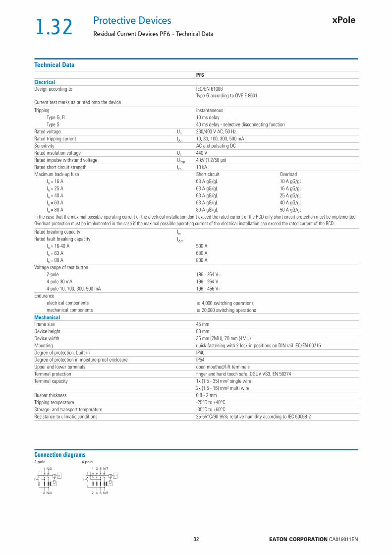
Technical DataPF6
ElectricalDesign according to
Current test marks as printed onto the device
IEC/EN 61008Type G according to ÖVE E 8601
Tripping instantaneousType G, R 10 ms delayType S 40 ms delay - selective disconnecting function
Rated voltage Un 230/400 V AC, 50 HzRated tripping current In 10, 30, 100, 300, 500 mASensitivity AC and pulsating DCRated insulation voltage Ui 440 VRated impulse withstand voltage Uimp 4 kV (1.2/50 μs)Rated short circuit strength Icn 10 kAMaximum back-up fuse Short circuit Overload
In = 16 A 63 A gG/gL 10 A gG/gLIn = 25 A 63 A gG/gL 16 A gG/gLIn = 40 A 63 A gG/gL 25 A gG/gLIn = 63 A 63 A gG/gL 40 A gG/gLIn = 80 A 80 A gG/gL 50 A gG/gL
In the case that the maximal possible operating current of the electrical installation don´t exceed the rated current of the RCD only short circuit protection must be implemented. Overload protection must be implemented in the case if the maximal possible operating current of the electrical installation can exceed the rated current of the RCD.
Rated breaking capacity ImRated fault breaking capacity Im
In = 16-40 A 500 AIn = 63 A 630 AIn = 80 A 800 A
Voltage range of test button2-pole 196 - 264 V~4-pole 30 mA 196 - 264 V~4-pole 10, 100, 300, 500 mA 196 - 456 V~
Enduranceelectrical components 4,000 switching operationsmechanical components 20,000 switching operations
MechanicalFrame size 45 mmDevice height 80 mmDevice width 35 mm (2MU), 70 mm (4MU)Mounting quick fastening with 2 lock-in positions on DIN rail IEC/EN 60715Degree of protection, built-in IP40Degree of protection in moisture-proof enclosure IP54Upper and lower terminals open mouthed/lift terminalsTerminal protection fi nger and hand touch safe, DGUV VS3, EN 50274Terminal capacity 1x (1.5 - 35) mm2 single wire
2x (1.5 - 16) mm2 multi wireBusbar thickness 0.8 - 2 mmTripping temperature -25°C to +40°CStorage- and transport temperature -35°C to +60°CResistance to climatic conditions 25-55°C/90-95% relative humidity according to IEC 60068-2
Connection diagrams2-pole 4-pole
1.33
33 EATON CORPORATION CA019011EN
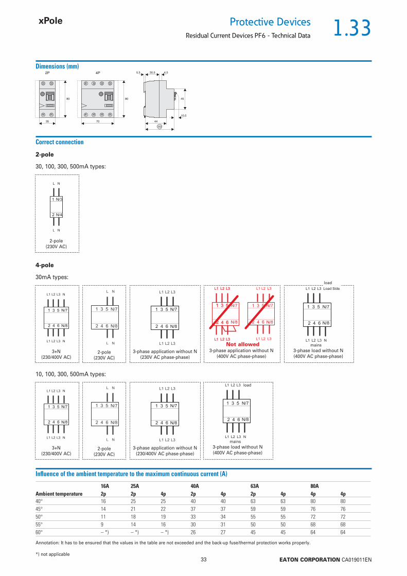
Protective DevicesResidual Current Devices PF6 - Technical Data
Dimensions (mm)
35
4580
10,5
4,530,5
44
60
5,52P
70
80
4P
Correct connection
30mA types:
10, 100, 300, 500mA types:
4-pole
30, 100, 300, 500mA types:
2-pole(230V AC)
2-pole
2-pole(230V AC)
3+N(230/400V AC)
3-phase application without N(230V AC phase-phase)
3-phase load without N(400V AC phase-phase)
3-phase application without N(400V AC phase-phase)
load
mains
2-pole(230V AC)
3+N(230/400V AC)
3-phase application without N(230/400V AC phase-phase)
3-phase load without N(400V AC phase-phase)
load
mains
Not allowed
Infl uence of the ambient temperature to the maximum continuous current (A)
16A 25A 40A 63A 80AAmbient temperature 2p 2p 4p 2p 4p 2p 4p 4p 4p40° 16 25 25 40 40 63 63 80 8045° 14 21 22 37 37 59 59 76 7650° 11 18 19 33 34 55 55 72 7255° 9 14 16 30 31 50 50 68 6860° – *) – *) – *) 26 27 45 45 64 64
Annotation: It has to be ensured that the values in the table are not exceeded and the back-up fuse/thermal protection works properly.
*) not applicable

1.34
34 EATON CORPORATION CA019011EN
Protective Devices
Residual Current Devices HNC xPole Home
• A compact range of residual current devices
for a wide range of applications
• For fault current/residual current protection
and additional protection
• Selection of nominal currents
• Comprehensive range of accessories
• Real contact position indicator
Description
sg01018_r

1.35
35 EATON CORPORATION CA019011EN
Protective DevicesResidual Current Devices HNC xPole Home
Type AC
Conditionally surge current-proof 250 A, type AC
25/0.03 HNC-25/2/003 194690 1/6040/0.03 HNC-40/2/003 194691 1/6063/0.03 HNC-63/2/003 194692 1/60
In/In
(A)TypeDesignation
Article No. Units perpackage
2-pole
25/0.03 HNC-25/4/003 194693 1/3040/0.03 HNC-40/4/003 194694 1/3063/0.03 HNC-63/4/003 194695 1/30
4-pole
Type A
Conditionally surge current-proof 250 A, sensitive to residual pulsating DC, type A
25/0.03 HNC-25/2/003-A 194684 1/6040/0.03 HNC-40/2/003-A 194685 1/6063/0.03 HNC-63/2/003-A 194686 1/60
2-pole
25/0.03 HNC-25/4/003-A 194687 1/3040/0.03 HNC-40/4/003-A 194688 1/3063/0.03 HNC-63/4/003-A 194689 1/30
4-pole
sg02118_r
sg01018_r
sg02118_r
sg01018_r
1.36
36 EATON CORPORATION CA019011EN
Protective Devices
Residual Current Devices HNC xPole Home - Technical Data
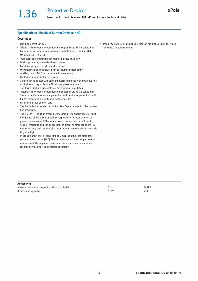
Specifi cations | Residual Current Devices HNC
Description
• Residual Current Devices• Tripping is line voltage-independent. Consequently, the RCD is suitable for
fault current/residual current protection and additional protection (ÖVE/ÖNORM E 8001-1 § 6.1.2)
• Twin-purpose terminal (lift/open-mouthed) above and below• Busbar positioning optionally above or below• Free terminal space despite installed busbar• Universal tripping signal switch can be mounted subsequently• Auxiliary switch Z-HK can be mounted subsequently• Contact position indicator red - green• Suitable for being used with standard fl uorescent tubes with or without elec-
tronical ballast (typically up to 20 units per phase conductor)• The device functions irrespective of the position of installation• Tripping is line voltage-independent. Consequently, the RCD is suitable for
“fault current/residual current protection” and “additional protection” within the the meaning of the applicable installation rules
• Mains connection at either side• The 4-pole device can also be used for 2- or 3-pole connection. See connec-
tion possibilities.• The test key “T” must be pressed every 6 month. The system operator must
be informed of this obligation and his responsibility in a way that can be proven (self-adhesive RCD-label enclosed). The test intervall of 6 month is valid for residential and similar applications. Under all other conditions (e.g. damply or dusty environments), it’s recommended to test in shorter intervalls (e.g. monthly).
• Pressing the test key “T” serves the only purpose of function testing the residual current device (RCD). This test does not make earthing resistance measurement (RE), or proper checking of the earth conductor condition redundant, which must be performed separately.
• Type -A: Protects against special forms of residual pulsating DC which have have not been smoothed
Accessories:Auxiliary switch for subsequent installation to the left Z-HK 248432Remote tripping module Z-FAM 248293

1.37
37 EATON CORPORATION CA019011EN
Protective DevicesResidual Current Devices HNC xPole Home - Technical Data
Technical DataHNC
ElectricalDesign according toCurrent test marks as printed onto the device
IEC/EN 61008
Tripping instantaneousRated voltage Un 230/400 V AC, 50 HzRated tripping current In 30 mASensitivity AC and pulsating DCRated insulation voltage Ui 440 VRated impulse withstand voltage Uimp 4 kV (1.2/50 μs)Rated short circuit strength Icn 6 kAMaximum back-up fuse Short circuit Overload
In = 25 A 63 A gG/gL 16 A gG/gLIn = 40 A 63 A gG/gL 25 A gG/gLIn = 63 A 63 A gG/gL 40 A gG/gL
In the case that the maximal possible operating current of the electrical installation don´t exceed the rated current of the RCD only short circuit protection must be implemented. Overload protection must be implemented in the case if the maximal possible operating current of the electrical installation can exceed the rated current of the RCD.
Rated breaking capacity ImRated fault breaking capacity Im
In = 25-40 A 500 AIn = 63 A 630 A
Voltage range of test button2-pole 196 - 264 V~4-pole 196 - 264 V~
Enduranceelectrical components 4,000 switching operationsmechanical components 20,000 switching operations
MechanicalFrame size 45 mmDevice height 80 mmDevice width 35 mm (2MU), 70 mm (4MU)Mounting quick fastening with 2 lock-in positions on DIN rail IEC/EN 60715Degree of protection, built-in IP40Upper and lower terminals open mouthed/lift terminalsTerminal protection fi nger and hand touch safe, DGUV VS3, EN 50274Terminal capacity 1.5 - 35 mm2 single wire
2 x 16 mm2 multi wireBusbar thickness 0.8 - 2 mmTripping temperature -25°C to +40°CStorage- and transport temperature -35°C to +60°CResistance to climatic conditions 25-55°C/90-95% relative humidity according to IEC 60068-2
Connection diagrams2-pole 4-pole
Dimensions (mm)
1.38
38 EATON CORPORATION CA019011EN
Protective Devices
Residual Current Devices HNC xPole Home - Technical Data
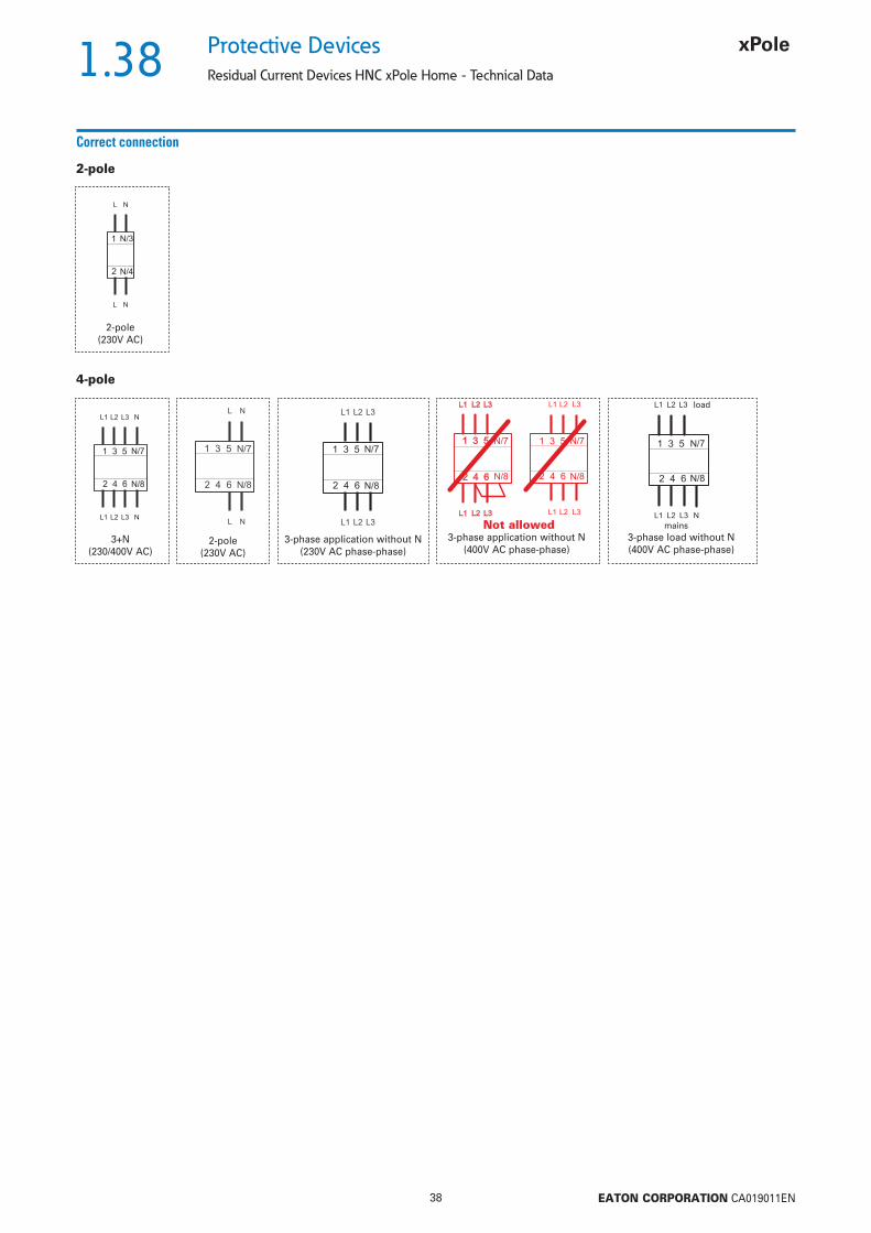
Correct connection
4-pole
2-pole(230V AC)
2-pole
2-pole(230V AC)
3+N(230/400V AC)
3-phase application without N(230V AC phase-phase)
3-phase load without N(400V AC phase-phase)
3-phase application without N(400V AC phase-phase)
load
mainsNot allowed

1.39
39 EATON CORPORATION CA019011EN
Protective DevicesResidual Current Relays PFR, Core Balance Transformers Z-WFR
• Especially matched residual current relays
and core balance transformers
• Nominal fault currents 0.3 A and 1 A
• Standard (-S/A) and frequency converter-
proof (-U) models
• Auxiliary switch can be mounted subse-
quently
Description
SG17311 SG47212
1.40
40 EATON CORPORATION CA019011EN
Protective Devices
Residual Current Relays PFR, Core Balance Transformers Z-WFR
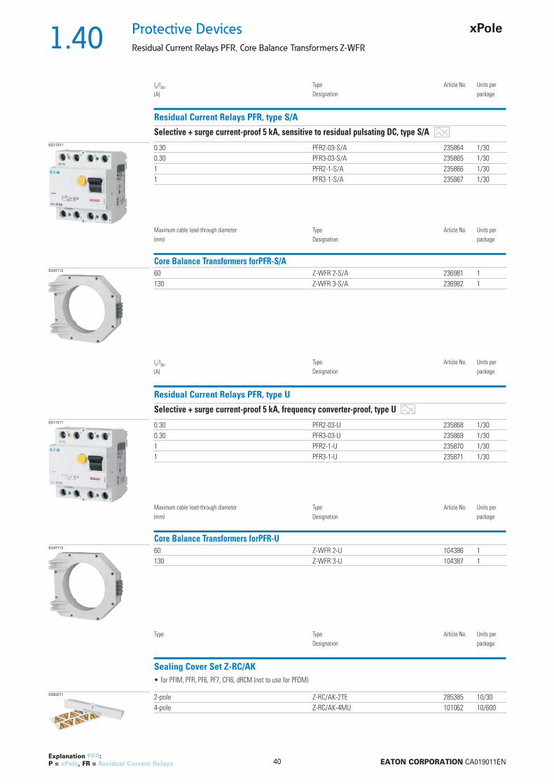
Residual Current Relays PFR, type S/A
Selective + surge current-proof 5 kA, sensitive to residual pulsating DC, type S/A
In/In
(A)TypeDesignation
Article No. Units perpackage
SG17311 0.30 PFR2-03-S/A 235864 1/300.30 PFR3-03-S/A 235865 1/301 PFR2-1-S/A 235866 1/301 PFR3-1-S/A 235867 1/30
Explanation PFR: P = xPole, FR = Residual Current Relays
Core Balance Transformers forPFR-S/A
Maximum cable lead-through diameter(mm)
TypeDesignation
Article No. Units perpackage
SG47112 60 Z-WFR 2-S/A 236981 1130 Z-WFR 3-S/A 236982 1
Residual Current Relays PFR, type U
Selective + surge current-proof 5 kA, frequency converter-proof, type U
In/In
(A)TypeDesignation
Article No. Units perpackage
SG17211 0.30 PFR2-03-U 235868 1/300.30 PFR3-03-U 235869 1/301 PFR2-1-U 235870 1/301 PFR3-1-U 235871 1/30
Core Balance Transformers forPFR-U
Maximum cable lead-through diameter(mm)
TypeDesignation
Article No. Units perpackage
SG47112 60 Z-WFR 2-U 104386 1130 Z-WFR 3-U 104387 1
Sealing Cover Set Z-RC/AK
Type TypeDesignation
Article No. Units perpackage
SG82011 2-pole Z-RC/AK-2TE 285385 10/304-pole Z-RC/AK-4MU 101062 10/600
• for PFIM, PFR, PF6, PF7, CFI6, dRCM (not to use for PFDM)

1.41
41 EATON CORPORATION CA019011EN
Protective DevicesResidual Current Relays PFR, Core Balance Transformers Z-WFR - Technical Data
Specifi cations | Residual Current Relays PFR, Core Balance Transformers Z-WFR
Description
• Residual Current Relays• Shape compatible with and suitable for standard busbar connection to other
devices of the P-series• Universal tripping signal switch, also suitable for PLS., PKN., Z-A. can be
mounted subsequently• Auxiliary switch Z-HK can be mounted subsequently• Contact position indicator red - green• Delayed types suitable for being used with standard fl uorescent tubes with
or without electronical ballast (30mA-RCD: 30 units per phase conductor, 100mA-RCD: 90 units per phase conductor).Notes: Depending of the fl uorescent lamp ballast manufacturer partly more possible. Symmetrical allocation of the fl uorescent lamp ballasts on all phases favourably. Shifting references of the fl uorescent lamp ballast manu-facturer consider.
• The test key “T” must be pressed every 6 month. The system operator must be informed of this obligation and his responsibility in a way that can be proven (self-adhesive RCD-label enclosed). The test intervall of 6 month is valid for residential and similar applications. Under all other conditions (e.g. damply or dusty environments), it’s recommended to test in shorter intervalls (e.g. monthly).
• Type -U: Suitable for speed-controlled drives with frequency converters in household, trade, and industry. Unwanted tripping is avoided thanks to a trip-ping characteristic designed particularly for frequency converters.See also explanation “Frequency Converter-Proof RCDs - What for?”Application according to ÖVE/ÖNORM E 8001 and Decision EN 219 (1989), VDE 0100, SEV 1000.
Accessories:Auxiliary switch for subsequent installation to the left Z-HK 248432Tripping signal contact for subsequent installation to the right Z-NHK 248434Compact enclosure KLV-TC-4 276241Sealing cover set Z-RC/AK-4MU 101062
Technical DataPFR
ElectricalDesign according toCurrent test marks as printed onto the device
IEC/EN 61008
Tripping 40 ms delay - selective disconnecting functionRated voltage Un 230/400 V AC, 50 HzRated tripping current In (0.1)*), 0.3 and 1 ARated current of relay contacts 25 A / 400 V~, 16 A / 230 V AC 15Max. Nennstrom 400 ASensitivity pulsating DCRated impulse withstand voltage Uimp 4 kV (1.2/50 μs)Voltage range of test button 184 - 440 V~Endurance
electrical components 4,000 switching operationsmechanical components 20,000 switching operations
MechanicalFrame size 45 mmDevice height 80 mmDevice width 70 mm (4MU)Mounting quick fastening with 2 lock-in positions on DIN rail IEC/EN 60715Degree of protection, built-in IP40Upper and lower terminals open mouthed/lift terminalsTerminal protection fi nger and hand touch safe, DGUV VS3, EN 50274Terminal capacity 1.5 - 35 mm2 single wire
2 x 16 mm2 multi wireBusbar thickness 0.8 - 2 mmControl line 1.5 - 2.5 mm2
Tripping temperature -25°C to +40°CStorage- and transport temperature -35°C to +60°CResistance to climatic conditions 25-55°C/90-95% relative humidity according to IEC 60068-2
*) see Important Information for Installation

1.42
42 EATON CORPORATION CA019011EN
Protective Devices
Residual Current Relays PFR, Core Balance Transformers Z-WFR - Technical Data
Connection diagramsRelais Core Balance Transformers
Dimensions (mm)
45
10,5
4,530,5
44
60
5,5
70
80
4PPFR Z-WFR 2-S/A / Z-WFR 2-U Z-WFR 3-S/A / Z-WFR 3-U
Impulse Contact Control Continuous Contact Control
Important Information for InstallationAll lines required for operation, L1, L2, and L3 including neutral N, must be routed through the transformer as follows:
Insulated lines must be laid bunched Copper railsMaximum distance d between copper rails 10 mm
Line voltage
Core balance transformer
Z-WFR
Contactor
Pushbutton control
Consumer
Earth
Line voltage
Core balance transformer
Z-WFR
Contactor
Timer, thermostat, etc.
Consumer
Earth
Two possible switching examples.Attention: • Connect terminals 1-4 of the relay to the terminals 1-4 of the transformer (see switching examples)!
1+2: secondary winding; 3+4: test winding• Supply terminals 13 and 15 as shown, so that the test circuit can work correkt!
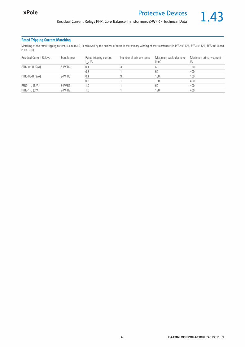
1.43
43 EATON CORPORATION CA019011EN
Protective DevicesResidual Current Relays PFR, Core Balance Transformers Z-WFR - Technical Data
Rated Tripping Current MatchingMatching of the rated tripping current, 0.1 or 0.3 A, is achieved by the number of turns in the primary winding of the transformer (in PFR2-03-S/A, PFR3-03-S/A, PFR2-03-U and PFR3-03-U).
Residual Current Relays Transformer Rated tripping current IN (A)
Number of primary turns Maximum cable diameter (mm)
Maximum primary current (A)
PFR2-03-U (S/A) Z-WFR2 0.1 3 60 1500.3 1 60 400
PFR3-03-U (S/A) Z-WFR3 0.1 3 130 1000.3 1 130 400
PFR2-1-U (S/A) Z-WFR2 1.0 1 60 400PFR3-1-U (S/A) Z-WFR3 1.0 1 130 400

1.44
44 EATON CORPORATION CA019011EN
Protective Devices
Residual Current Devices PFDM
• Advanced residual current devices for the 125
A nominal current range
• For fault current/residual current protection
and additional protection
• Auxiliary switch
• Selective types
Description
SG31011
PHASE OUT
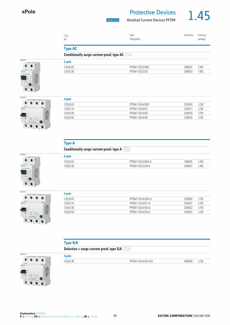
1.45
45 EATON CORPORATION CA019011EN
Protective DevicesResidual Current Devices PFDM
Explanation PFDM: P = xPole, FD = Residual Current Devices 125 A, M = 10 kA
Type AC
Conditionally surge current-proof, type ACSG30611
125/0.03 PFDM-125/2/003 249031 1/60125/0.30 PFDM-125/2/03 249033 1/60
In/In
(A)TypeDesignation
Article No. Units perpackage
2-pole
SG31011
125/0.03 PFDM-125/4/003 235916 1/30125/0.10 PFDM-125/4/01 235917 1/30125/0.30 PFDM-125/4/03 235918 1/30125/0.50 PFDM-125/4/05 235919 1/30
4-pole
Type A
Conditionally surge current-proof, type ASG30611
125/0.03 PFDM-125/2/003-A 249035 1/60125/0.30 PFDM-125/2/03-A 249037 1/60
2-pole
SG31011
125/0.03 PFDM-125/4/003-A 235920 1/30125/0.10 PFDM-125/4/01-A 235921 1/30125/0.30 PFDM-125/4/03-A 235922 1/30125/0.50 PFDM-125/4/05-A 235923 1/30
4-pole
Type S/A
Selective + surge current-proof, type S/ASG31011
125/0.30 PFDM-125/4/03-S/A 285639 1/30
4-pole
PHASE OUT
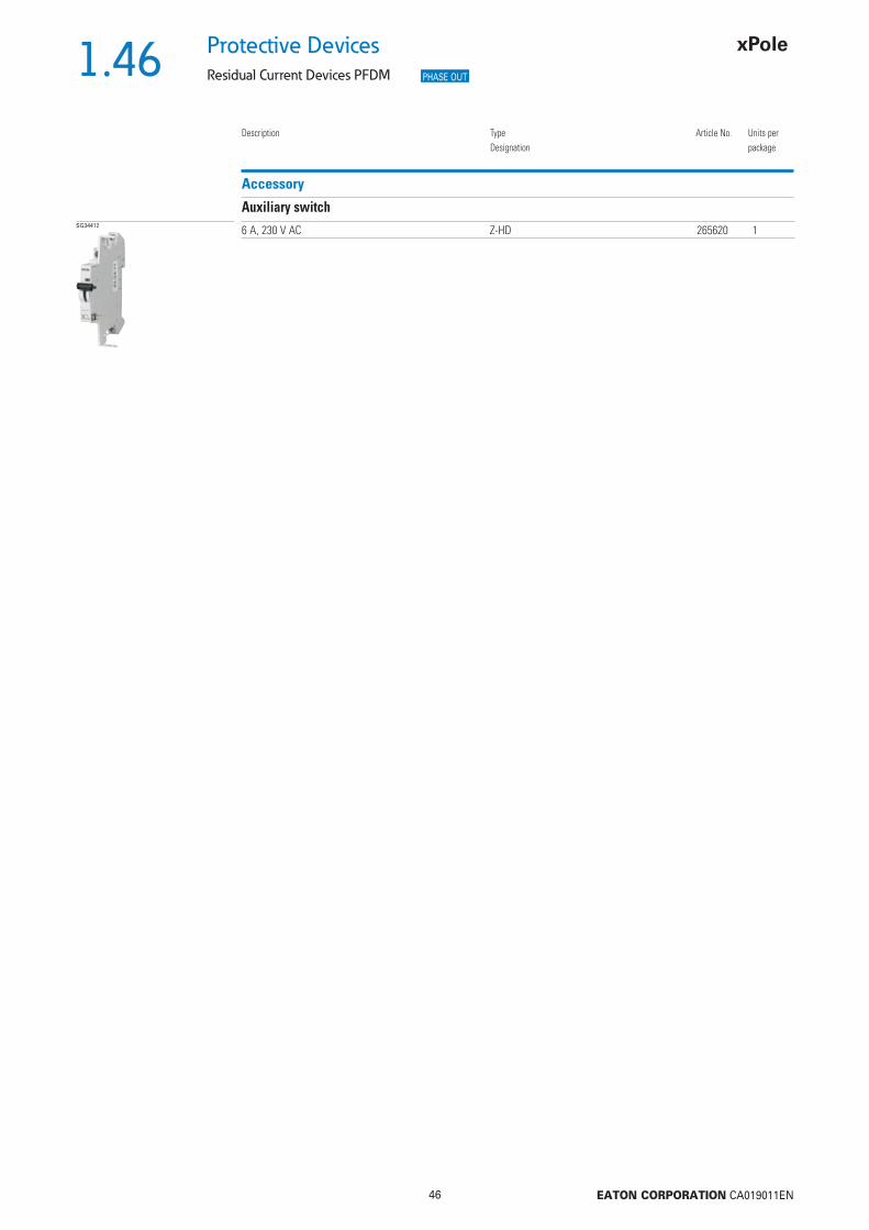
1.46
46 EATON CORPORATION CA019011EN
Protective Devices
Residual Current Devices PFDM
Description TypeDesignation
Article No. Units perpackage
Accessory
Auxiliary switchSG34412 6 A, 230 V AC Z-HD 265620 1
PHASE OUT

1.47
47 EATON CORPORATION CA019011EN
Protective DevicesResidual Current Devices PFDM - Technical Data
Technical DataPFDM
ElectricalDesign according toCurrent test marks as printed onto the device
IEC/EN 61008
Tripping instantaneousType S/A 50 ms delay - selective disconnecting function
Rated voltage Un 230/400 V AC, 50 HzRated tripping current In 30, 100, 300, 500 mASensitivity AC and pulsating DCRated short circuit strength Icn 10 kA with back-up fuseMaximum back-up fuse short circuit 125 A gG/gLRated breaking capacity Im 1250 ARated fault breaking capacity Im
Voltage range of test button2-pole 100 - 250 V~4-pole 185 - 440 V~
Enduranceelectrical components 4,000 switching operationsmechanical components 20,000 switching operations
MechanicalFrame size 45 mmDevice height 80 mmDevice width 36 mm (2P), 72 mm (4P)Mounting quick fastening on DIN rail IEC/EN 60715Degree of protection, built-in IP40Upper and lower terminals open mouthed/lift terminalsTerminal protection fi nger and hand touch safe, DGUV VS3, EN 50274Terminal capacity 1,5 - 50 mm2
Busbar thickness 0.8 - 2 mmTripping temperature -25°C to +40°CStorage- and transport temperature -35°C to +75°CResistance to climatic conditions 25-55°C/90-95% relative humidity according to IEC 60068-2
Specifi cations | Residual Current Devices PFDM
Description
• Residual Current Devices• Tripping is line voltage-independent. Consequently, the RCD is suitable for the
protection of humans and additional protection (ÖVE/ÖNORM E 8001-1§ 6.1.2)• Twin-purpose terminal (lift/open-mouthed) above and below• Not busbar-compatible with other devices of the P-series• Auxiliary switch Z-HD can be mounted subsequently• Contact position indicator red - green• The device functions irrespective of the position of installation• Tripping is line voltage-independent. Consequently, the RCD is suitable for
“fault current/residual current protection” and “additional protection” within the the meaning of the applicable installation rules
• Mains connection at either side• The test key “T” must be pressed every 6 month. The system operator must
be informed of this obligation and his responsibility in a way that can be proven (self-adhesive RCD-label enclosed). The test intervall of 6 month is valid for residential and similar applications. Under all other conditions (e.g. damply or dusty environments), it’s recommended to test in shorter intervalls (e.g. monthly).
• Pressing the test key “T” serves the only purpose of function testing the residual current device (RCD). This test does not make earthing resistance measurement (RE), or proper checking of the earth conductor condition redundant, which must be performed separately.
• Type -A: Additionally protects against special forms of residual pulsating DC which have not been smoothed
• Type -S/A: Compulsory for systems with surge arresters downstream of the RCD (ÖVE/ÖNORM E 8001-1 § 12.1.5)
Accessories:Auxiliary switch for subsequent installation to the left Z-HD 265620
PHASE OUT
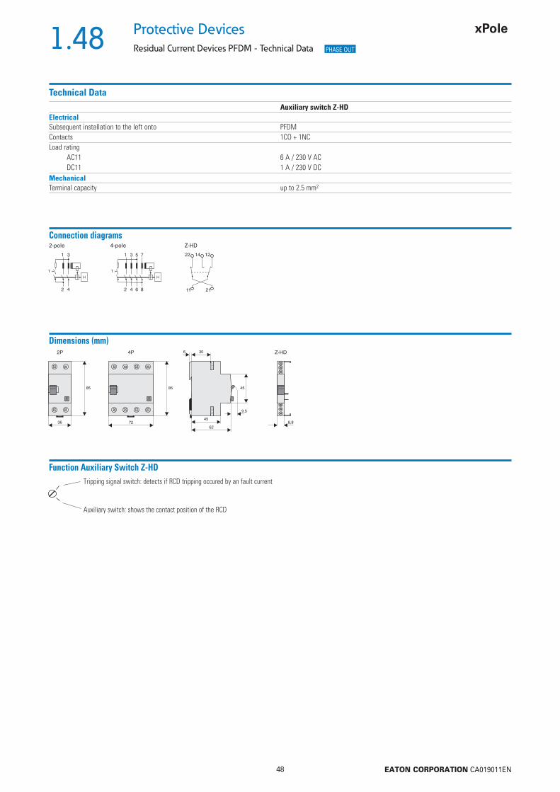
1.48
48 EATON CORPORATION CA019011EN
Protective Devices
Residual Current Devices PFDM - Technical Data
Auxiliary switch Z-HDElectricalSubsequent installation to the left onto PFDMContacts 1CO + 1NCLoad rating
AC11 6 A / 230 V ACDC11 1 A / 230 V DC
MechanicalTerminal capacity up to 2.5 mm2
Connection diagrams2-pole 4-pole Z-HD
Technical Data
Dimensions (mm)
Function Auxiliary Switch Z-HDTripping signal switch: detects if RCD tripping occured by an fault current
Auxiliary switch: shows the contact position of the RCD
PHASE OUT

1.49
49 EATON CORPORATION CA019011EN
Protective DevicesResidual Current Devices dRCM Digital
• Line voltage independent RCCB for fault or
additional protection with additional digital
features
• System Monitoring: Preventive information /
warning before the RCD trips in case of leak-
age currents
– Integrated auxiliary contact(s)
– Local Indication
• New level of accuracy -> Reduced unwanted
tripping
• Local status indication of residual current
through 3 LEDs
• No monthly test required
• Comprehensive range of accessories
• Real contact position indicator
• Fault current tripping indicator
• Automatic re-setting possible
• Transparent designation plate
Description
SG08310
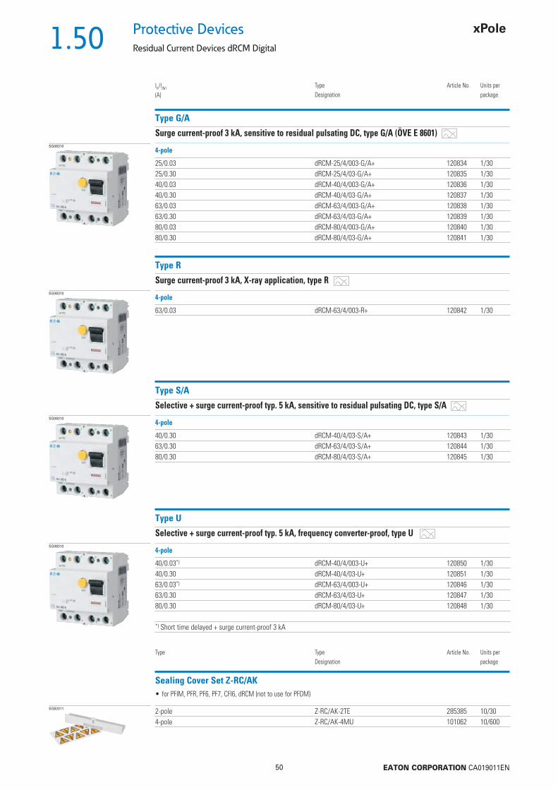
1.50
50 EATON CORPORATION CA019011EN
Protective Devices
Residual Current Devices dRCM Digital
Type G/A
Surge current-proof 3 kA, sensitive to residual pulsating DC, type G/A (ÖVE E 8601)
In/In
(A)TypeDesignation
Article No. Units perpackage
SG08310
25/0.03 dRCM-25/4/003-G/A+ 120834 1/3025/0.30 dRCM-25/4/03-G/A+ 120835 1/3040/0.03 dRCM-40/4/003-G/A+ 120836 1/3040/0.30 dRCM-40/4/03-G/A+ 120837 1/3063/0.03 dRCM-63/4/003-G/A+ 120838 1/3063/0.30 dRCM-63/4/03-G/A+ 120839 1/3080/0.03 dRCM-80/4/003-G/A+ 120840 1/3080/0.30 dRCM-80/4/03-G/A+ 120841 1/30
4-pole
Type R
Surge current-proof 3 kA, X-ray application, type RSG08310
63/0.03 dRCM-63/4/003-R+ 120842 1/30
4-pole
Type S/A
Selective + surge current-proof typ. 5 kA, sensitive to residual pulsating DC, type S/ASG08310
40/0.30 dRCM-40/4/03-S/A+ 120843 1/3063/0.30 dRCM-63/4/03-S/A+ 120844 1/3080/0.30 dRCM-80/4/03-S/A+ 120845 1/30
4-pole
Type U
Selective + surge current-proof typ. 5 kA, frequency converter-proof, type USG08310
40/0.03*) dRCM-40/4/003-U+ 120850 1/3040/0.30 dRCM-40/4/03-U+ 120851 1/3063/0.03*) dRCM-63/4/003-U+ 120846 1/3063/0.30 dRCM-63/4/03-U+ 120847 1/3080/0.30 dRCM-80/4/03-U+ 120848 1/30
*) Short time delayed + surge current-proof 3 kA
4-pole
Sealing Cover Set Z-RC/AK
Type TypeDesignation
Article No. Units perpackage
SG82011 2-pole Z-RC/AK-2TE 285385 10/304-pole Z-RC/AK-4MU 101062 10/600
• for PFIM, PFR, PF6, PF7, CFI6, dRCM (not to use for PFDM)

1.51
51 EATON CORPORATION CA019011EN
Protective DevicesResidual Current Devices dRCM Digital - Technical Data
Specifi cations | Residual Current Devices dRCM Digital
Description
• Residual Current Devices• Shape compatible with and suitable for standard busbar connection to other
devices of the P-series• Twin-purpose terminal (lift/open-mouthed) above and below• Busbar positioning optionally above or below• Free terminal space despite installed busbar• Universal tripping signal switch, also suitable for PLS., PKN., ZP-A. can be
mounted subsequently• Auxiliary switch Z-HK can be mounted subsequently• Contact position indicator red - green• Tripping indicator white - blue• Additional safety - possibility to seal - possibility to lock in ON and OFF position• Delayed types suitable for being used with standard fl uorescent tubes with
or without electronical ballast (30mA-RCD: 30 units per phase conductor).Notes: Depending of the fl uorescent lamp ballast manufacturer partly more possible. Symmetrical allocation of the fl uorescent lamp ballasts on all phases favourably. Shifting references of the fl uorescent lamp ballast manu-facturer consider.
• The device functions irrespective of the position of installation• Tripping is line voltage-independent. Consequently, the RCD is suitable for
“fault current/residual current protection” and “additional protection” within the meaning of the applicable installation rules
• Mains connection at either side• The 4-pole device can also be used for 3- and 2-pole connection.
See connection possibilities.• The test key “T” must be pressed every year. The system operator must be
informed of this obligation and his responsibility in a way that can be proven. The yearly test interval is only valid for residential and similar applications. Under all other conditions (e.g. damply or dusty environment), it‘s precom-mended to test in shorter intervals (e.g. monthly).A test is further needed if red and yellow LED are on together.
• Pressing the test key “T” serves the only purpose of function testing the residual current device (RCD). This test does not make earthing resistance measurement (RE), or proper checking of the earth conductor condition redundant, which must be performed separately.
• Functioning- The green LED becomes active at 0-30% In
- The yellow LED becomes active at 30-50% In
- The red LED becomes active at >50% In
• Potential-free relay (NO contact, in parallel with the yellow LED, up to 1 A ohmic load / 230 V~) for external prewarning function. Bistabile, means the warning stays on also when the breaker trips, until reset.
• Type -A: Protects against special forms of residual pulsating DC which have have not been smoothed
• Type -G: High reliability against unwanted tripping. Compulsory for any circuit where personal injury or damage to property may occur in case of unwanted tripping (ÖVE/ÖNORM E 8001-1 § 12.1.6)
• Type -G/A: Additionally protects against special forms of residual pulsating DC which have not been smoothed
• Type -R: To aviod unwanted tripping due to X-ray devices• Type -S: Selective residual current device sensitive to AC, type -S.
Compulsory for systems with surge arresters downstream of the RCD (ÖVE/ÖNORM E 8001-1 § 12.1.5).
• Type -S/A: Additionally protects against special forms of residual pulsating DC which have not been smoothed
• Type -U: Suitable for speed-controlled drives with frequency converters in household, trade, and industry.Unwanted tripping is avoided thanks to a tripping characteristic designed particularly for frequency converters.See also explanation “Frequency Converter-Proof RCDs - What for?”Application according to ÖVE/ÖNORM E 8001-1 and Decision EN 219 (1989), VDE 0100, SEV 1000.
Accessories:Auxiliary switch for subsequent installation to the left Z-HK 248432Tripping signal contact for subsequent installation to the right Z-NHK 248434Remote control and automatic switching device Z-FW/LP 248296Compact enclosure KLV-TC-4 276241Sealing cover set Z-RC/AK-4MU 101062
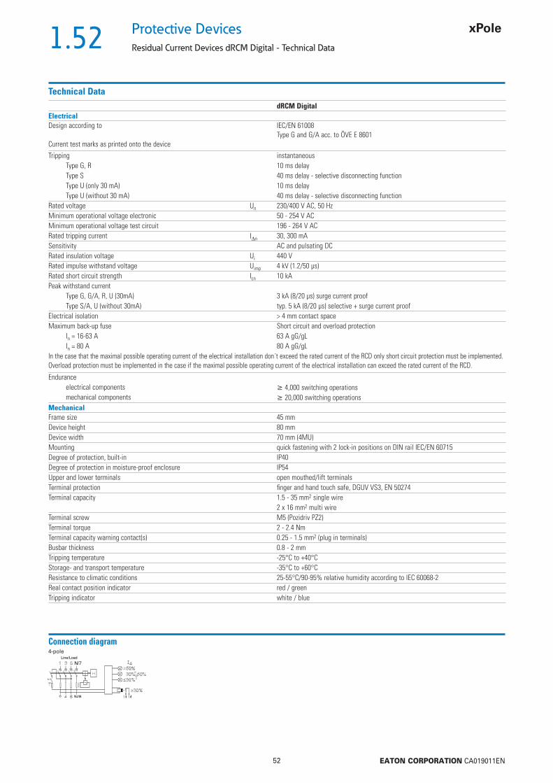
1.52
52 EATON CORPORATION CA019011EN
Protective Devices
Residual Current Devices dRCM Digital - Technical Data
Technical DatadRCM Digital
ElectricalDesign according to
Current test marks as printed onto the device
IEC/EN 61008Type G and G/A acc. to ÖVE E 8601
Tripping instantaneousType G, R 10 ms delayType S 40 ms delay - selective disconnecting functionType U (only 30 mA) 10 ms delayType U (without 30 mA) 40 ms delay - selective disconnecting function
Rated voltage Un 230/400 V AC, 50 HzMinimum operational voltage electronic 50 - 254 V ACMinimum operational voltage test circuit 196 - 264 V ACRated tripping current In 30, 300 mASensitivity AC and pulsating DCRated insulation voltage Ui 440 VRated impulse withstand voltage Uimp 4 kV (1.2/50 μs)Rated short circuit strength Icn 10 kAPeak withstand current
Type G, G/A, R, U (30mA) 3 kA (8/20 μs) surge current proofType S/A, U (without 30mA) typ. 5 kA (8/20 μs) selective + surge current proof
Electrical isolation > 4 mm contact spaceMaximum back-up fuse Short circuit and overload protection
In = 16-63 A 63 A gG/gLIn = 80 A 80 A gG/gL
In the case that the maximal possible operating current of the electrical installation don´t exceed the rated current of the RCD only short circuit protection must be implemented. Overload protection must be implemented in the case if the maximal possible operating current of the electrical installation can exceed the rated current of the RCD.
Enduranceelectrical components 4,000 switching operationsmechanical components 20,000 switching operations
MechanicalFrame size 45 mmDevice height 80 mmDevice width 70 mm (4MU)Mounting quick fastening with 2 lock-in positions on DIN rail IEC/EN 60715Degree of protection, built-in IP40Degree of protection in moisture-proof enclosure IP54Upper and lower terminals open mouthed/lift terminalsTerminal protection fi nger and hand touch safe, DGUV VS3, EN 50274Terminal capacity 1.5 - 35 mm2 single wire
2 x 16 mm2 multi wireTerminal screw M5 (Pozidriv PZ2)Terminal torque 2 - 2.4 NmTerminal capacity warning contact(s) 0.25 - 1.5 mm2 (plug in terminals)Busbar thickness 0.8 - 2 mmTripping temperature -25°C to +40°CStorage- and transport temperature -35°C to +60°CResistance to climatic conditions 25-55°C/90-95% relative humidity according to IEC 60068-2Real contact position indicator red / greenTripping indicator white / blue
Connection diagram4-pole
Line/Load
N/7
N/8

1.53
53 EATON CORPORATION CA019011EN
Protective DevicesResidual Current Devices dRCM Digital - Technical Data
Local Indication RCCB
Remote Indication
Status indication LED red / yellow / greenPermanent light green Normal operation
Permanent light yellow The measured residual current is bigger than 30% of the nominal tripping value.
Permanent light red The measured residual current is bigger than 50% of the nominal tripping value.
Standard Version 1 contact NO up to 230V AC, 2 terminals, 1 A ohmic loadOptional Version (available upon request) 1 NO + 1 NC up to 110V AC/contact, 2x2 terminals, 1 A ohmic loadTerminal capacity of contacts 0.25 - 1.5 mm2
Dimensions (mm)
Electronic works within 50-254 V AC !
Correct connection30, 300mA types:
3+N(230/400V AC)
3-phase application without N(230V AC phase-phase)
1+N(230V AC)
3-phase load without N(400V AC phase-phase)
load
mains3-phase application without N
(400V AC phase-phase)
Not allowed
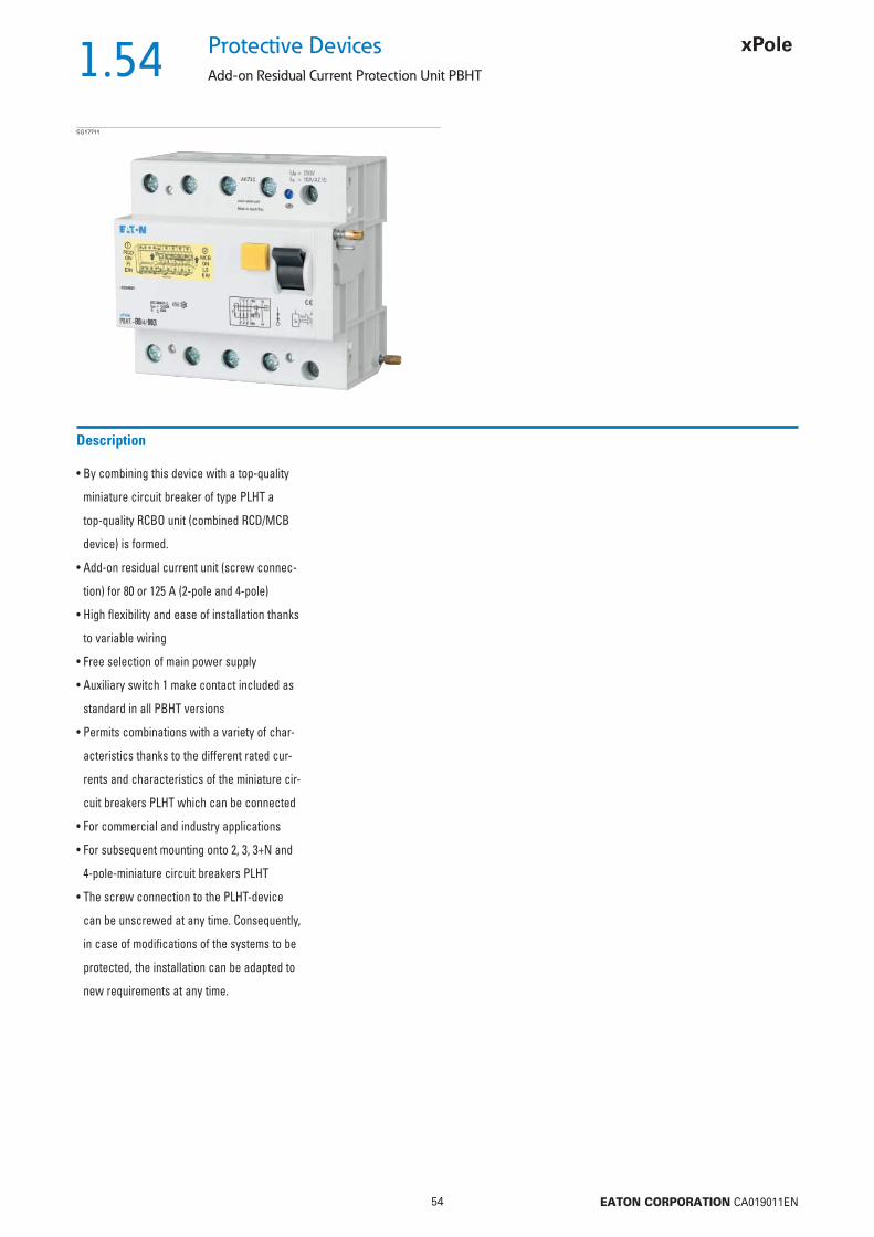
1.54
54 EATON CORPORATION CA019011EN
Protective Devices
Add-on Residual Current Protection Unit PBHT
• By combining this device with a top-quality
miniature circuit breaker of type PLHT a
top-quality RCBO unit (combined RCD/MCB
device) is formed.
• Add-on residual current unit (screw connec-
tion) for 80 or 125 A (2-pole and 4-pole)
• High fl exibility and ease of installation thanks
to variable wiring
• Free selection of main power supply
• Auxiliary switch 1 make contact included as
standard in all PBHT versions
• Permits combinations with a variety of char-
acteristics thanks to the different rated cur-
rents and characteristics of the miniature cir-
cuit breakers PLHT which can be connected
• For commercial and industry applications
• For subsequent mounting onto 2, 3, 3+N and
4-pole-miniature circuit breakers PLHT
• The screw connection to the PLHT-device
can be unscrewed at any time. Consequently,
in case of modifi cations of the systems to be
protected, the installation can be adapted to
new requirements at any time.
Description
SG17711
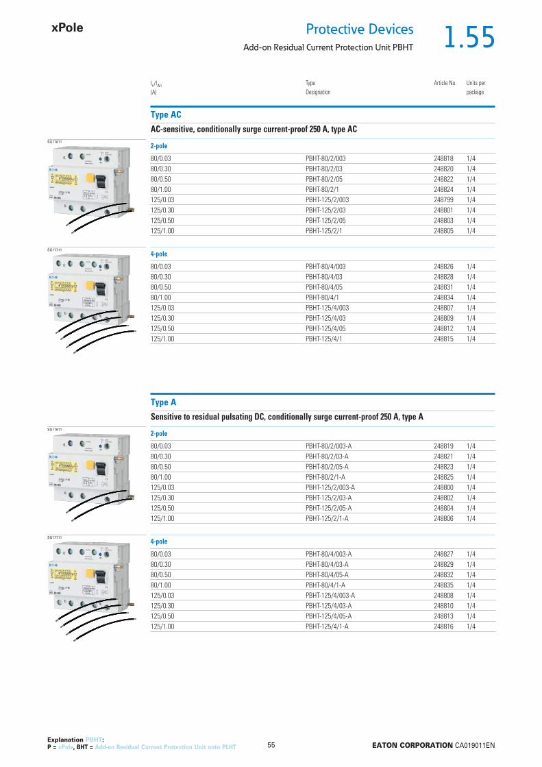
1.55
55 EATON CORPORATION CA019011EN
Protective DevicesAdd-on Residual Current Protection Unit PBHT
Type AC
AC-sensitive, conditionally surge current-proof 250 A, type ACSG17611
80/0.03 PBHT-80/2/003 248818 1/480/0.30 PBHT-80/2/03 248820 1/480/0.50 PBHT-80/2/05 248822 1/480/1.00 PBHT-80/2/1 248824 1/4125/0.03 PBHT-125/2/003 248799 1/4125/0.30 PBHT-125/2/03 248801 1/4125/0.50 PBHT-125/2/05 248803 1/4125/1.00 PBHT-125/2/1 248805 1/4
In/In
(A)TypeDesignation
Article No. Units perpackage
2-pole
SG17711
80/0.03 PBHT-80/4/003 248826 1/480/0.30 PBHT-80/4/03 248828 1/480/0.50 PBHT-80/4/05 248831 1/480/1.00 PBHT-80/4/1 248834 1/4125/0.03 PBHT-125/4/003 248807 1/4125/0.30 PBHT-125/4/03 248809 1/4125/0.50 PBHT-125/4/05 248812 1/4125/1.00 PBHT-125/4/1 248815 1/4
4-pole
Type A
Sensitive to residual pulsating DC, conditionally surge current-proof 250 A, type ASG17611
80/0.03 PBHT-80/2/003-A 248819 1/480/0.30 PBHT-80/2/03-A 248821 1/480/0.50 PBHT-80/2/05-A 248823 1/480/1.00 PBHT-80/2/1-A 248825 1/4125/0.03 PBHT-125/2/003-A 248800 1/4125/0.30 PBHT-125/2/03-A 248802 1/4125/0.50 PBHT-125/2/05-A 248804 1/4125/1.00 PBHT-125/2/1-A 248806 1/4
2-pole
SG17711
80/0.03 PBHT-80/4/003-A 248827 1/480/0.30 PBHT-80/4/03-A 248829 1/480/0.50 PBHT-80/4/05-A 248832 1/480/1.00 PBHT-80/4/1-A 248835 1/4125/0.03 PBHT-125/4/003-A 248808 1/4125/0.30 PBHT-125/4/03-A 248810 1/4125/0.50 PBHT-125/4/05-A 248813 1/4125/1.00 PBHT-125/4/1-A 248816 1/4
4-pole
Explanation PBHT: P = xPole, BHT = Add-on Residual Current Protection Unit onto PLHT

1.56
56 EATON CORPORATION CA019011EN
Protective Devices
Add-on Residual Current Protection Unit PBHT
Explanation PBHT: P = xPole, BHT = Add-on Residual Current Protection Unit onto PLHT
Type S/A
Selective + surge current-proof 5 kA, type S/A
In/In
(A)TypeDesignation
Article No. Units perpackage
SG17711
80/0.30 PBHT-80/4/03-S/A 248830 1/480/0.50 PBHT-80/4/05-S/A 248833 1/480/1.00 PBHT-80/4/1-S/A 248836 1/4125/0.30 PBHT-125/4/03-S/A 248811 1/4125/0.50 PBHT-125/4/05-S/A 248814 1/4125/1.00 PBHT-125/4/1-S/A 248817 1/4
4-pole
Operational voltage range V~
TypeDesignation
Article No. Units perpackage
Accessory
Shunt trip releaseSG09411 110-415 Z-BHASA/230 248445 8
12-60 Z-BHASA/24 248444 8
Specifi cations | Add-on Residual Current Protection Unit PBHT
Description
• By combination with miniature circuit breaker PLHT => RCBO-Unit (MCCB)• Add-on residual current unit (screw connection) for 80 or 125 A (2-pole and
4-pole)• High fl exibility and ease of installation thanks to variable wiring (400 mm fl ex-
ible connection wires 2p = 2 units, 4p = 4 units included in the set)• Free selection of main power supply • Auxiliary switch 1 make contact included as standard in all PBHT versions• Permits combinations with a variety of characteristics thanks to the different
rated currents and characteristics of the miniature circuit breakers PLHT which can be connected
• For commercial and industry applications• For subsequent mounting onto 2, 3, 3+N and 4-pole-miniature circuit breakers
PLHT• Toggle (serves as switch position- and tripping indicator)
• The screw connection to the PLHT-device can be unscrewed at any time. Consequently, in case of modifi cations of the systems to be protected, the installation can be adapted to new requirements at any time.
• The test key “T” must be pressed every 6 month. The system operator must be informed of this obligation and his responsibility in a way that can be proven (self-adhesive RCD-label enclosed). The test intervall of 6 month is valid for residential and similar applications. Under all other conditions (e.g. damply or dusty environments), it’s recommended to test in shorter intervalls (e.g. monthly).
• Pressing the test key “T” serves the only purpose of function testing the residual current device (RCD). This test does not make earthing resistance measurement (RE), or proper checking of the earth conductor condition redundant, which must be performed separately.
Accessories:Flexible connection wires (connection to PLHT) are included in the standard set:
2-pole 80 A 2 x 16 mm2 (á 400 mm)4-pole 80 A 4 x 16 mm2 (á 400 mm)2-pole 125 A 2 x 35 mm2 (á 400 mm)4-pole 125 A 4 x 35 mm2 (á 400 mm)
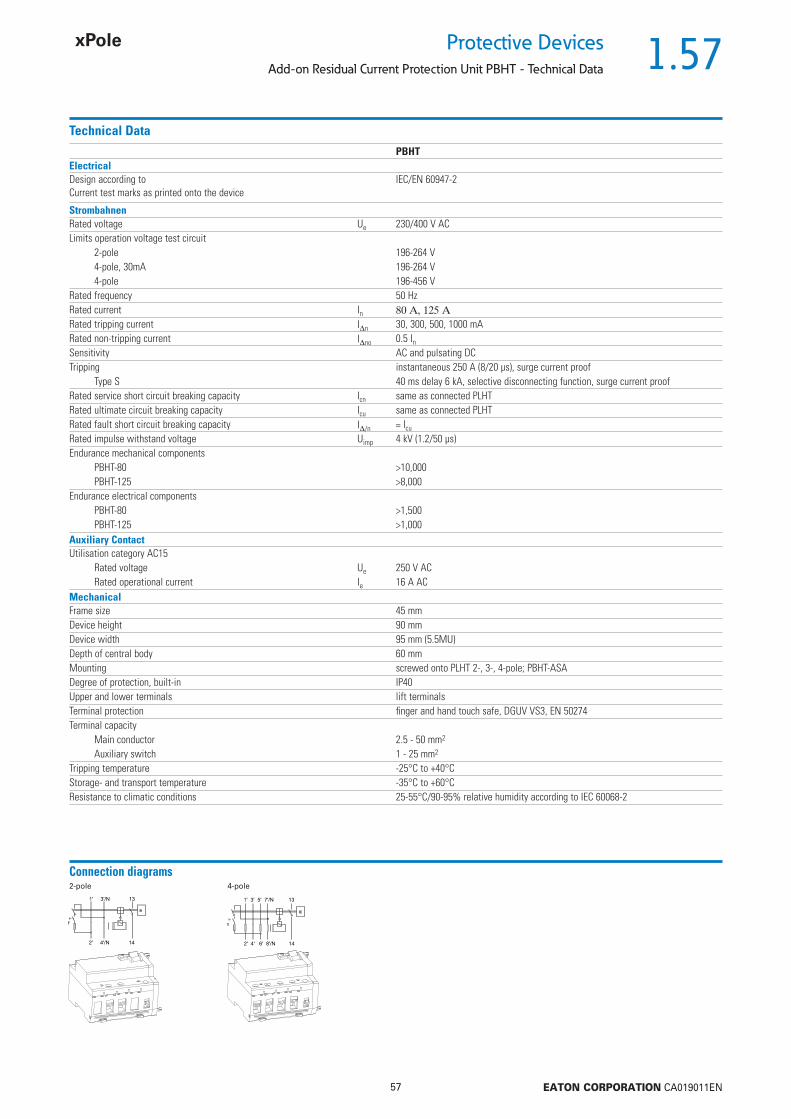
1.57
57 EATON CORPORATION CA019011EN
Protective DevicesAdd-on Residual Current Protection Unit PBHT - Technical Data
Technical DataPBHT
ElectricalDesign according toCurrent test marks as printed onto the device
IEC/EN 60947-2
StrombahnenRated voltage Ue 230/400 V ACLimits operation voltage test circuit
2-pole 196-264 V4-pole, 30mA 196-264 V4-pole 196-456 V
Rated frequency 50 HzRated current In Rated tripping current In 30, 300, 500, 1000 mARated non-tripping current Ino 0.5 InSensitivity AC and pulsating DCTripping instantaneous 250 A (8/20 μs), surge current proof
Type S 40 ms delay 6 kA, selective disconnecting function, surge current proofRated service short circuit breaking capacity Icn same as connected PLHTRated ultimate circuit breaking capacity Icu same as connected PLHTRated fault short circuit breaking capacity I/n = Icu
Rated impulse withstand voltage Uimp 4 kV (1.2/50 μs)Endurance mechanical components
PBHT-80 >10,000PBHT-125 >8,000
Endurance electrical componentsPBHT-80 >1,500PBHT-125 >1,000
Auxiliary ContactUtilisation category AC15
Rated voltage Ue 250 V ACRated operational current Ie 16 A AC
MechanicalFrame size 45 mmDevice height 90 mmDevice width 95 mm (5.5MU)Depth of central body 60 mmMounting screwed onto PLHT 2-, 3-, 4-pole; PBHT-ASADegree of protection, built-in IP40Upper and lower terminals lift terminalsTerminal protection fi nger and hand touch safe, DGUV VS3, EN 50274Terminal capacity
Main conductor 2.5 - 50 mm2
Auxiliary switch 1 - 25 mm2
Tripping temperature -25°C to +40°CStorage- and transport temperature -35°C to +60°CResistance to climatic conditions 25-55°C/90-95% relative humidity according to IEC 60068-2
Connection diagrams2-pole 4-pole
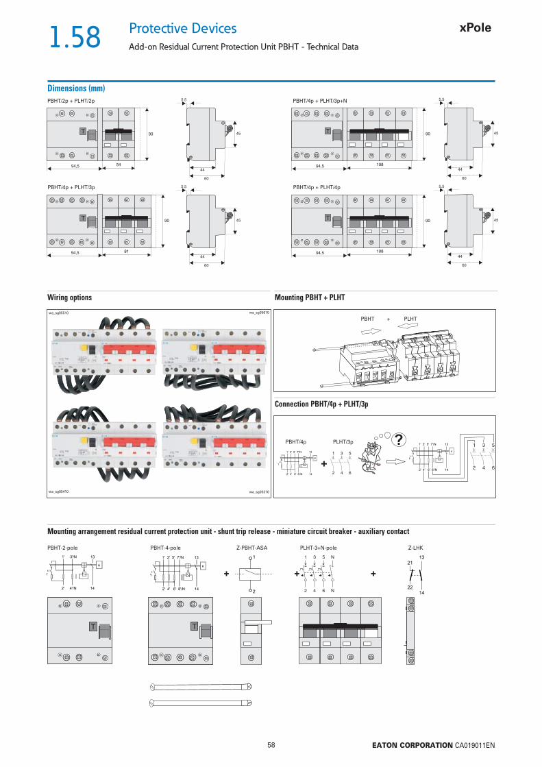
1.58
58 EATON CORPORATION CA019011EN
Protective Devices
Add-on Residual Current Protection Unit PBHT - Technical Data
Dimensions (mm)PBHT/2p + PLHT/2p PBHT/4p + PLHT/3p+N
PBHT/4p + PLHT/3p PBHT/4p + PLHT/4p
Mounting PBHT + PLHTWiring options
PBHT + PLHTwa_sg05510
wa_sg05410
wa_sg05610
wa_sg05310
Connection PBHT/4p + PLHT/3p
PBHT/4p PLHT/3p
Mounting arrangement residual current protection unit - shunt trip release - miniature circuit breaker - auxiliary contact
PBHT-2-pole PBHT-4-pole Z-PBHT-ASA PLHT-3+N-pole Z-LHK
+ + +

1.59
59 EATON CORPORATION CA019011EN
Protective DevicesAdd-on Residual Current Protection Unit PBHT - Technical Data
Accessories for PBHT
Shunt trip release Z-BHASA
• Can be mounted subsequently• Contact position indicator red/green• Marking labels can be fi tted• Wide operational voltage range• Suffi cient power of extra low voltage source must be ensured
PBHT-ASA/24: min. 90 VA• Screws for mounting included PBHT => BHASA => PLHT
Technical DataZ-BHASA/24 Z-BHASA/230
ElectricalMinimum pulse duration 15 ms 10 msInternal resistance 2 W 130 W Duty 100% 100%Tripping time < 20 ms < 20 msPeak withstand voltage (1.2/50 μs) 2 kV 2 kVEndurance >4,000 switching operations >4,000 switching operationsAC voltage rangeResponding limit 8 V 70 VOperational voltage range 12-60 V 110-415 VMaximum current consumption during switch-on 1.4-7 A 3.4 A (at 230 V)Current fl ow time at max. current consumption 4.0 ms 4.5 msDC voltage rangeResponding limit 11 V 90 VOperational voltage range 12-60 V 110-230 VMaximum current consumption during switch-on 1.7 A typ. 1.7 A typ.Current fl ow time at max. current consumption 2 ms 4 msMechanicalFrame size 45 mm 45 mmDevice height 90 mm 90 mmDevice width 27 mm 27 mmMounting quick fastening on DIN rail IEC/EN 60715Degree of protection, built-in IP40 IP40Upper and lower terminals lift terminals lift terminalsTerminal capacity 2.5-30 mm2 2.5-30 mm2
Terminal torque 4 Nm 4 Nm
Connection diagram
Dimensions (mm)

1.60
60 EATON CORPORATION CA019011EN
Protective Devices
Leakage Current Monitor PDIM
• Reliable, universal monitoring of residual cur-
rent
• RCD characteristic and sensitivity are freely
selectable
• Compact design, with integrated transformer
• DIN mounting, compatible with shapes and
standard busbar connections of other Xpole
devices
• Local status indication of residual current
through 3 LEDs
• 2 potential-free signalling contacts
Description
SG31211

1.61
61 EATON CORPORATION CA019011EN
Protective DevicesLeakage Current Monitor PDIM
Leakage Current Monitor PDIM
+ , instantaneous, G , S => adjustableSG31211
40/0.03; 0.1; 0.3; 0.5; 1 PDIM-40/4 111760 1/30100/0.03; 0.1; 0.3; 0.5; 1 PDIM-100/4 111761 1/30
In/In
(A)TypeDesignation
Article No. Units perpackage
4-pole
Specifi cations | Leakage Current Monitor PDIM
Description
• Shape compatible with and suitable for standard busbar connection to other devices of the P-series
• Twin-purpose terminal (lift/open-mouthed) above and below• Busbar positioning optionally above or below• Free terminal space despite installed busbar• Power supply via ‘OR’ disjunction of the 4 conductors• Electronic functioning (line-voltage dependent)• The device functions irrespective of the position of installation• Mains connection at either side• The 4-pole device can also be used for 3-pole connection.
For this purpose use terminals 1-2, 3-4, and 5-6.• The 4-pole switch can also be used as a 2-pole switch
For this purpose use terminals 5-6 and N-N.• 2 potential-free relays (make contact, in parallel with the yellow and red LED)
(up to 10 A / 230 V~)Functioning• The green LED becomes active at 0-30% of the preset In.
The yellow LED becomes active at 30-50% of the preset In. The red LED becomes active at >50% of the preset In.
• The yellow LED turns off again when the identifi ed residual current is <30% of the preset In.
• The red LED turns off again when the identifi ed residual current is <50% of the preset In.
• Only one LED will be active at a time.• An output relay will always be switched simultaneously with the yellow or
red LED• Depending on the setting of the type of RCD (instantaneous, G, S), the residu-
al current needs to fl ow a suffi ciently long time before an action is triggered.Test function• The rotary coding switch for the RCD switch function is to be set to “TEST”.
The device then alternately simulates residual currents of 30% and 50% of the In. In this process, the yellow and red LED fl ash alternately (1 Hz), both output relays remain permanently energised.
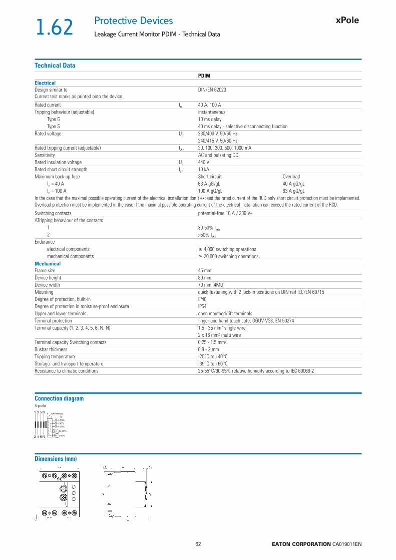
1.62
62 EATON CORPORATION CA019011EN
Protective Devices
Leakage Current Monitor PDIM - Technical Data
Technical DataPDIM
ElectricalDesign similar toCurrent test marks as printed onto the device
DIN/EN 62020
Rated current In 40 A, 100 ATripping behaviour (adjustable) instantaneous
Type G 10 ms delayType S 40 ms delay - selective disconnecting function
Rated voltage Un 230/400 V, 50/60 Hz240/415 V, 50/60 Hz
Rated tripping current (adjustable) In 30, 100, 300, 500, 1000 mASensitivity AC and pulsating DCRated insulation voltage Ui 440 VRated short circuit strength Icn 10 kAMaximum back-up fuse Short circuit Overload
In = 40 A 63 A gG/gL 40 A gG/gLIn = 100 A 100 A gG/gL 63 A gG/gL
In the case that the maximal possible operating current of the electrical installation don´t exceed the rated current of the RCD only short circuit protection must be implemented. Overload protection must be implemented in the case if the maximal possible operating current of the electrical installation can exceed the rated current of the RCD.
Switching contacts potential-free 10 A / 230 V~ATripping behaviour of the contacts
1 30-50% In
2 >50% In
Enduranceelectrical components 4,000 switching operationsmechanical components 20,000 switching operations
MechanicalFrame size 45 mmDevice height 80 mmDevice width 70 mm (4MU)Mounting quick fastening with 2 lock-in positions on DIN rail IEC/EN 60715Degree of protection, built-in IP40Degree of protection in moisture-proof enclosure IP54Upper and lower terminals open mouthed/lift terminalsTerminal protection fi nger and hand touch safe, DGUV VS3, EN 50274Terminal capacity (1, 2, 3, 4, 5, 6, N, N) 1.5 - 35 mm2 single wire
2 x 16 mm2 multi wireTerminal capacity Switching contacts 0.25 - 1.5 mm2
Busbar thickness 0.8 - 2 mmTripping temperature -25°C to +40°CStorage- and transport temperature -35°C to +60°CResistance to climatic conditions 25-55°C/90-95% relative humidity according to IEC 60068-2
Connection diagram4-pole
Dimensions (mm)
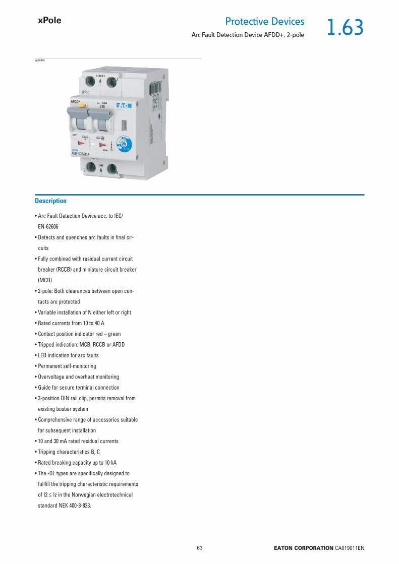
1.63
63 EATON CORPORATION CA019011EN
Protective DevicesArc Fault Detection Device AFDD+, 2-pole
• Arc Fault Detection Device acc. to IEC/
EN-62606
• Detects and quenches arc faults in fi nal cir-
cuits
• Fully combined with residual current circuit
breaker (RCCB) and miniature circuit breaker
(MCB)
• 2-pole: Both clearances between open con-
tacts are protected
• Variable installation of N either left or right
• Rated currents from 10 to 40 A
• Contact position indicator red – green
• Tripped indication: MCB, RCCB or AFDD
• LED indication for arc faults
• Permanent self-monitoring
• Overvoltage and overheat monitoring
• Guide for secure terminal connection
• 3-position DIN rail clip, permits removal from
existing busbar system
• Comprehensive range of accessories suitable
for subsequent installation
• 10 and 30 mA rated residual currents
• Tripping characteristics B, C
• Rated breaking capacity up to 10 kA
• The -OL types are specifi cally designed to
fullfi ll the tripping characteristic requirements
of I2 Iz in the Norwegian electrotechnical
standard NEK 400-8-823.
Description
sg06416
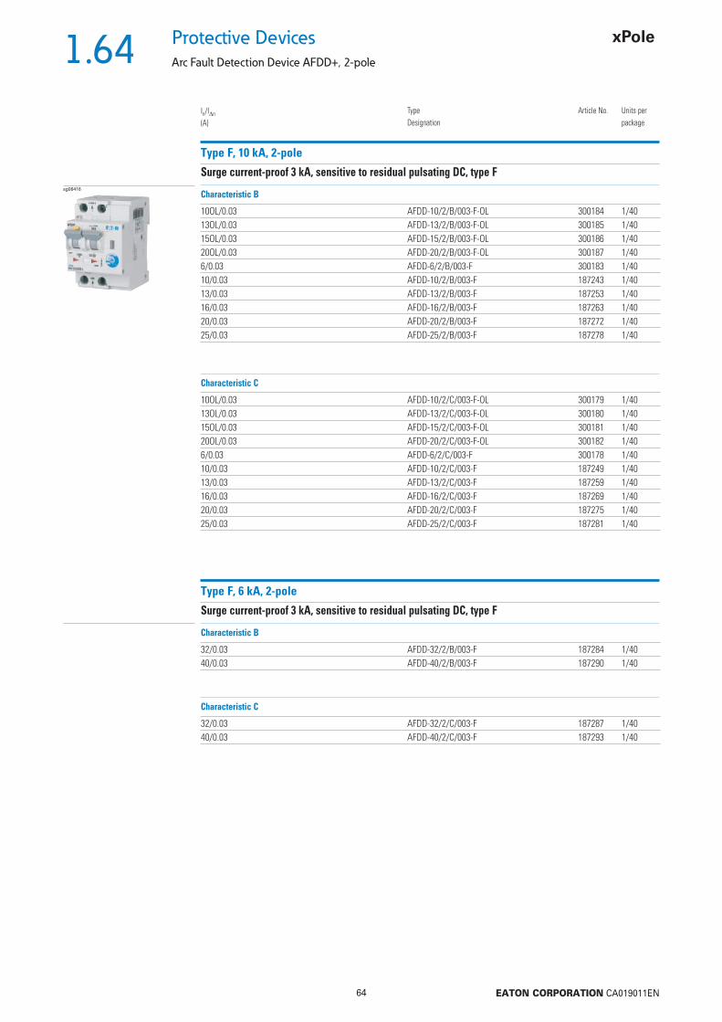
1.64
64 EATON CORPORATION CA019011EN
Protective Devices
Arc Fault Detection Device AFDD+, 2-pole
Type F, 10 kA, 2-pole
Surge current-proof 3 kA, sensitive to residual pulsating DC, type Fsg06416
10OL/0.03 AFDD-10/2/B/003-F-OL 300184 1/4013OL/0.03 AFDD-13/2/B/003-F-OL 300185 1/4015OL/0.03 AFDD-15/2/B/003-F-OL 300186 1/4020OL/0.03 AFDD-20/2/B/003-F-OL 300187 1/406/0.03 AFDD-6/2/B/003-F 300183 1/4010/0.03 AFDD-10/2/B/003-F 187243 1/4013/0.03 AFDD-13/2/B/003-F 187253 1/4016/0.03 AFDD-16/2/B/003-F 187263 1/4020/0.03 AFDD-20/2/B/003-F 187272 1/4025/0.03 AFDD-25/2/B/003-F 187278 1/40
In/In
(A)TypeDesignation
Article No. Units perpackage
Characteristic B
10OL/0.03 AFDD-10/2/C/003-F-OL 300179 1/4013OL/0.03 AFDD-13/2/C/003-F-OL 300180 1/4015OL/0.03 AFDD-15/2/C/003-F-OL 300181 1/4020OL/0.03 AFDD-20/2/C/003-F-OL 300182 1/406/0.03 AFDD-6/2/C/003-F 300178 1/4010/0.03 AFDD-10/2/C/003-F 187249 1/4013/0.03 AFDD-13/2/C/003-F 187259 1/4016/0.03 AFDD-16/2/C/003-F 187269 1/4020/0.03 AFDD-20/2/C/003-F 187275 1/4025/0.03 AFDD-25/2/C/003-F 187281 1/40
Characteristic C
Type F, 6 kA, 2-pole
Surge current-proof 3 kA, sensitive to residual pulsating DC, type F
32/0.03 AFDD-32/2/B/003-F 187284 1/4040/0.03 AFDD-40/2/B/003-F 187290 1/40
Characteristic B
32/0.03 AFDD-32/2/C/003-F 187287 1/4040/0.03 AFDD-40/2/C/003-F 187293 1/40
Characteristic C

1.65
65 EATON CORPORATION CA019011EN
Protective DevicesArc Fault Detection Device AFDD+, 2-pole
Type G/A, 10 kA, 2-pole
Surge current-proof 3 kA, sensitive to residual pulsating DC, type G/Asg06416
In/In
(A)TypeDesignation
Article No. Units perpackage
Characteristic B
Characteristic C
Type G/A, 6 kA, 2-pole
Surge current-proof 3 kA, sensitive to residual pulsating DC, type G/A
Characteristic B
Characteristic C
10OL/0.03 AFDD-10/2/B/003-G/A-OL 300163 1/4013OL/0.03 AFDD-13/2/B/003-G/A-OL 300166 1/4015OL/0.03 AFDD-15/2/B/003-G/A-OL 300167 1/4020OL/0.03 AFDD-20/2/B/003-G/A-OL 300172 1/406/0.01 AFDD-6/2/B/001-G/A 300193 1/4010/0.01 AFDD-10/2/B/001-G/A 300194 1/4013/0.01 AFDD-13/2/B/001-G/A 300195 1/4016/0.01 AFDD-16/2/B/001-G/A 300196 1/406/0.03 AFDD-6/2/B/003-G/A 300161 1/4010/0.03 AFDD-10/2/B/003-G/A 300162 1/4013/0.03 AFDD-13/2/B/003-G/A 300165 1/4016/0.03 AFDD-16/2/B/003-G/A 300168 1/4020/0.03 AFDD-20/2/B/003-G/A 300170 1/4025/0.03 AFDD-25/2/B/003-G/A 300173 1/40
32/0.03 AFDD-32/2/B/003-G/A 300174 1/4040/0.03 AFDD-40/2/B/003-G/A 300222 1/40
32/0.03 AFDD-32/2/C/003-G/A 300158 1/4040/0.03 AFDD-40/2/C/003-G/A 300159 1/40
10OL/0.03 AFDD-10/2/C/003-G/A-OL 300148 1/4013OL/0.03 AFDD-13/2/C/003-G/A-OL 300150 1/4015OL/0.03 AFDD-15/2/C/003-G/A-OL 300151 1/4020OL/0.03 AFDD-20/2/C/003-G/A-OL 300154 1/406/0.01 AFDD-6/2/C/001-G/A 300188 1/4010/0.01 AFDD-10/2/C/001-G/A 300189 1/4013/0.01 AFDD-13/2/C/001-G/A 300191 1/4016/0.01 AFDD-16/2/C/001-G/A 300192 1/406/0.03 AFDD-6/2/C/003-G/A 300138 1/4010/0.03 AFDD-10/2/C/003-G/A 300147 1/4013/0.03 AFDD-13/2/C/003-G/A 300149 1/4016/0.03 AFDD-16/2/C/003-G/A 300152 1/4020/0.03 AFDD-20/2/C/003-G/A 300153 1/4025/0.03 AFDD-25/2/C/003-G/A 300155 1/40
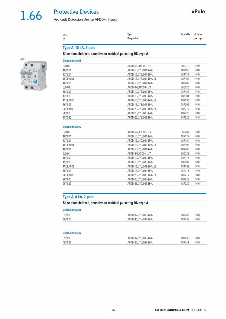
1.66
66 EATON CORPORATION CA019011EN
Protective Devices
Arc Fault Detection Device AFDD+, 2-pole
In/In
(A)TypeDesignation
Article No. Units perpackage
Type A, 10 kA, 2-pole
Short-time delayed, sensitive to residual pulsating DC, type Asg06416
6/0.01 AFDD-6/2/B/001-Li/A 300210 1/4010/0.01 AFDD-10/2/B/001-Li/A 187166 1/4013/0.01 AFDD-13/2/B/001-Li/A 187178 1/4015OL/0.01 AFDD-15/2/B/001-Li/A-OL 187190 1/4016/0.01 AFDD-16/2/B/001-Li/A 187202 1/406/0.03 AFDD-6/2/B/003-Li/A 300226 1/4010/0.03 AFDD-10/2/B/003-Li/A 187169 1/4013/0.03 AFDD-13/2/B/003-Li/A 187181 1/4015OL/0.03 AFDD-15/2/B/003-Li/A-OL 187193 1/4016/0.03 AFDD-16/2/B/003-Li/A 187205 1/4020OL/0.03 AFDD-20/2/B/003-Li/A-OL 187214 1/4020/0.03 AFDD-20/2/B/003-Li/A 187220 1/4025/0.03 AFDD-25/2/B/003-Li/A 187226 1/40
In/In
(A)TypeDesignation
Article No. Units perpackage
Characteristic B
6/0.01 AFDD-6/2/C/001-Li/A 300207 1/4010/0.01 AFDD-10/2/C/001-Li/A 187172 1/4013/0.01 AFDD-13/2/C/001-Li/A 187184 1/4015OL/0.01 AFDD-15/2/C/001-Li/A-OL 187196 1/4016/0.01 AFDD-16/2/C/001-Li/A 187208 1/406/0.01 AFDD-6/2/C/001-Li/A 300223 1/4010/0.03 AFDD-10/2/C/003-Li/A 187175 1/4013/0.03 AFDD-13/2/C/003-Li/A 187187 1/4015OL/0.03 AFDD-15/2/C/003-Li/A-OL 187199 1/4016/0.03 AFDD-16/2/C/003-Li/A 187211 1/4020OL/0.03 AFDD-20/2/C/003-Li/A-OL 187217 1/4020/0.03 AFDD-20/2/C/003-Li/A 187223 1/4025/0.03 AFDD-25/2/C/003-Li/A 187229 1/40
Characteristic C
Type A, 6 kA, 2-pole
Short-time delayed, sensitive to residual pulsating DC, type A
32/0.03 AFDD-32/2/B/003-Li/A 187232 1/4040/0.03 AFDD-40/2/B/003-Li/A 187238 1/40
Characteristic B
32/0.03 AFDD-32/2/C/003-Li/A 187235 1/4040/0.03 AFDD-40/2/C/003-Li/A 187241 1/40
Characteristic C
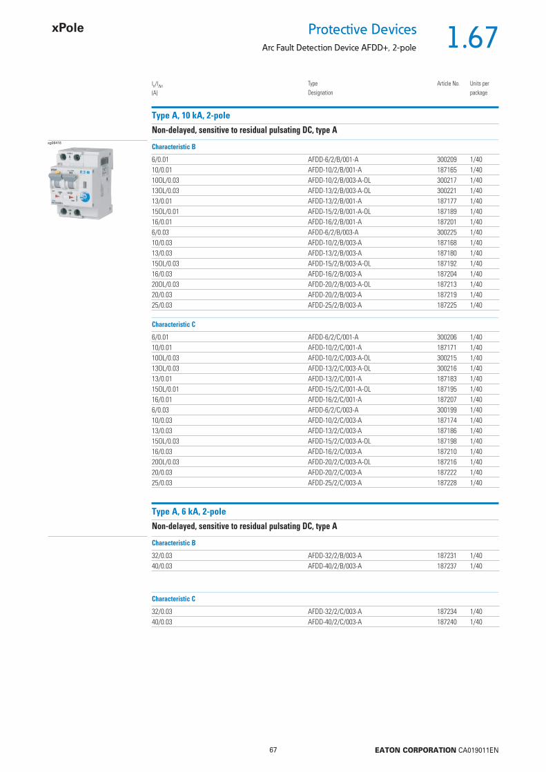
1.67
67 EATON CORPORATION CA019011EN
Protective DevicesArc Fault Detection Device AFDD+, 2-pole
Type A, 10 kA, 2-pole
Non-delayed, sensitive to residual pulsating DC, type Asg06416
6/0.01 AFDD-6/2/B/001-A 300209 1/4010/0.01 AFDD-10/2/B/001-A 187165 1/4010OL/0.03 AFDD-10/2/B/003-A-OL 300217 1/4013OL/0.03 AFDD-13/2/B/003-A-OL 300221 1/4013/0.01 AFDD-13/2/B/001-A 187177 1/4015OL/0.01 AFDD-15/2/B/001-A-OL 187189 1/4016/0.01 AFDD-16/2/B/001-A 187201 1/406/0.03 AFDD-6/2/B/003-A 300225 1/4010/0.03 AFDD-10/2/B/003-A 187168 1/4013/0.03 AFDD-13/2/B/003-A 187180 1/4015OL/0.03 AFDD-15/2/B/003-A-OL 187192 1/4016/0.03 AFDD-16/2/B/003-A 187204 1/4020OL/0.03 AFDD-20/2/B/003-A-OL 187213 1/4020/0.03 AFDD-20/2/B/003-A 187219 1/4025/0.03 AFDD-25/2/B/003-A 187225 1/40
In/In
(A)TypeDesignation
Article No. Units perpackage
Characteristic B
6/0.01 AFDD-6/2/C/001-A 300206 1/4010/0.01 AFDD-10/2/C/001-A 187171 1/4010OL/0.03 AFDD-10/2/C/003-A-OL 300215 1/4013OL/0.03 AFDD-13/2/C/003-A-OL 300216 1/4013/0.01 AFDD-13/2/C/001-A 187183 1/4015OL/0.01 AFDD-15/2/C/001-A-OL 187195 1/4016/0.01 AFDD-16/2/C/001-A 187207 1/406/0.03 AFDD-6/2/C/003-A 300199 1/4010/0.03 AFDD-10/2/C/003-A 187174 1/4013/0.03 AFDD-13/2/C/003-A 187186 1/4015OL/0.03 AFDD-15/2/C/003-A-OL 187198 1/4016/0.03 AFDD-16/2/C/003-A 187210 1/4020OL/0.03 AFDD-20/2/C/003-A-OL 187216 1/4020/0.03 AFDD-20/2/C/003-A 187222 1/4025/0.03 AFDD-25/2/C/003-A 187228 1/40
Characteristic C
Type A, 6 kA, 2-pole
Non-delayed, sensitive to residual pulsating DC, type A
32/0.03 AFDD-32/2/B/003-A 187231 1/4040/0.03 AFDD-40/2/B/003-A 187237 1/40
Characteristic B
32/0.03 AFDD-32/2/C/003-A 187234 1/4040/0.03 AFDD-40/2/C/003-A 187240 1/40
Characteristic C

1.68
68 EATON CORPORATION CA019011EN
Protective Devices
Arc Fault Detection Device AFDD+, 2-pole
Type AC, 10 kA, 2-pole
Non-delayed, alternating-current-sensitive, type ACsg06416
6/0.01 AFDD-6/2/B/001 300208 1/4010/0.01 AFDD-10/2/B/001 187164 1/4013/0.01 AFDD-13/2/B/001 187176 1/4015OL/0.01 AFDD-15/2/B/001-OL 187188 1/4016/0.01 AFDD-16/2/B/001 187200 1/406/0.03 AFDD-6/2/C/003 300224 1/4010/0.03 AFDD-10/2/B/003 187167 1/4013/0.03 AFDD-13/2/B/003 187179 1/4015OL/0.03 AFDD-15/2/B/003-OL 187191 1/4016/0.03 AFDD-16/2/B/003 187203 1/4020OL/0.03 AFDD-20/2/B/003-OL 187212 1/4020/0.03 AFDD-20/2/B/003 187218 1/4025/0.03 AFDD-25/2/B/003 187224 1/40
In/In
(A)TypeDesignation
Article No. Units perpackage
Characteristic B
6/0.01 AFDD-6/2/C/001 300205 1/4010/0.01 AFDD-10/2/C/001 187170 1/4013/0.01 AFDD-13/2/C/001 187182 1/4015OL/0.01 AFDD-15/2/C/001-OL 187194 1/4016/0.01 AFDD-16/2/C/001 187206 1/406/0.03 AFDD-6/2/C/003 300197 1/4010/0.03 AFDD-10/2/C/003 187173 1/4013/0.03 AFDD-13/2/C/003 187185 1/4015OL/0.03 AFDD-15/2/C/003-OL 187197 1/4016/0.03 AFDD-16/2/C/003 187209 1/4020OL/0.03 AFDD-20/2/C/003-OL 187215 1/4020/0.03 AFDD-20/2/C/003 187221 1/4025/0.03 AFDD-25/2/C/003 187227 1/40
Characteristic C
Type AC, 6 kA, 2-pole
Non-delayed, alternating-current-sensitive, type AC
32/0.03 AFDD-32/2/B/003 187230 1/4040/0.03 AFDD-40/2/B/003 187236 1/40
Characteristic B
32/0.03 AFDD-32/2/C/003 187233 1/4040/0.03 AFDD-40/2/C/003 187239 1/40
Characteristic C

1.69
69 EATON CORPORATION CA019011EN
Protective DevicesArc Fault Detection Device AFDD+, 2-pole, Technical Data
Specifi cations | Arc Fault Detection Device AFDD+, 2-pole
Description
• Arc Fault Detection Device acc. to IEC/EN-62606• Line-voltage-independent RCBO (combined switch) acc. to IEC/EN 61009• 2-pole: Both clearances between open contacts are protected• Variable installation of N either left or right• Tripped indication: CB, RCD or AFDD• LED indication for arc faults• Compatible with standard busbar• Twin-purpose terminal (lift/open-mouthed) above and below• Busbar positioning optionally above or below• Free terminal space despite installed busbar• Guide for secure terminal connection• Switching toggle (MCB component) in colour designating the rated current• Contact position indicator red - green• Comprehensive range of accessories can be mounted subsequently• The test key “T” must be pressed every 6 month. The system operator must
be informed of this obligation and his responsibility in a way that can be proven (self-adhesive RCD-label enclosed). The test intervall of 6 month is valid for residential and similar applications. Under all other conditions (e.g. damply or dusty environments), it’s recommended to test in shorter intervalls (e.g. monthly).
• Pressing the test key “T” serves the only purpose of function testing the residual current device (RCD). This test does not make earthing resistance measurement (RE), or proper checking of the earth conductor condition redundant, which must be performed separately.
• The line length (one-way) from the AFDD+ to the socket outlet should not exceed 70 m. This guarantees that arc faults can be detected reliably.
• Type -A: Protects against special forms of residual pulsating DC which have have not been smoothed
• Type -Li/A: As Type –A, but in addition it is short-time delayed. Highly reliable against unwanted tripping.
• Type -G: 10 ms time delay in order to avoid unwanted tripping (e.g. during thunderstorms). -> acc. to ÖVE E 8601.
• Type -F: Sensitive to pulsating DC residual current and detection of multi-frequency residual currents up to 1 kHz • Increased protection due to the detection of mixed frequencies • Higher load rating with DC residual currents up to 10mA • Reduction of nuisance tripping thanks to time delayed tripping and increased current withstand capability > 3kA • Recommended for washing machines, dish washers, or motor applications with single-phase drives• Acc. to IEC/EN 62423.
• OL tpyes: Specifi cally designed to fullfi ll the tripping characteristic requirements of I2 Iz in the Norwegian electrotechnical standard NEK 400-8-823.
Error memory:The AFDD+ saves the last reason for tripping at an arc fault. By turning off thedevice, press and hold the test key “T” and simultaneously turn on the lasterror can be queried again.
Accessories:Auxiliary switch for subsequent installation ZP-IHK 286052Auxiliary switch ZP-NHK 248437
ZP-WHK 286053Shunt trip release ZP-ASA/.. 248438, 248439Busbars EVG-2PHAS/4AFDD; ZV-SS; ZV-L1/N; ZV-L2/L3; ZV-ADP; ZV-AEK
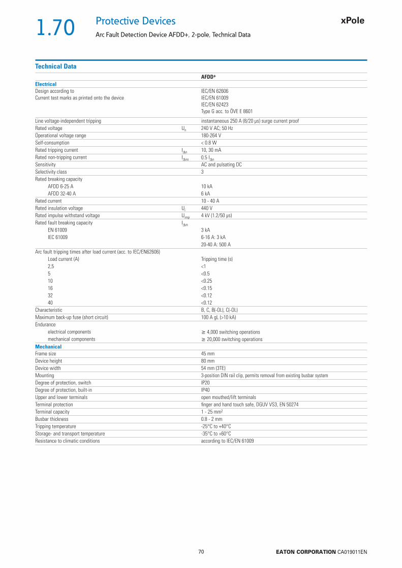
1.70
70 EATON CORPORATION CA019011EN
Protective Devices
Arc Fault Detection Device AFDD+, 2-pole, Technical Data
Technical DataAFDD+
ElectricalDesign according toCurrent test marks as printed onto the device
IEC/EN 62606IEC/EN 61009IEC/EN 62423Type G acc. to ÖVE E 8601
Line voltage-independent tripping instantaneous 250 A (8/20 μs) surge current proofRated voltage Un 240 V AC; 50 HzOperational voltage range 180-264 VSelf-consumption < 0.8 WRated tripping current In 10, 30 mARated non-tripping current Ino 0.5 In
Sensitivity AC and pulsating DCSelectivity class 3Rated breaking capacity
AFDD 6-25 A 10 kAAFDD 32-40 A 6 kA
Rated current 10 - 40 ARated insulation voltage Ui 440 VRated impulse withstand voltage Uimp 4 kV (1.2/50 μs)Rated fault breaking capacity Im
EN 61009 3 kAIEC 61009 6-16 A: 3 kA
20-40 A: 500 AArc fault tripping times after load current (acc. to IEC/EN62606)
Load current (A) Tripping time (s)2,5 <15 <0.510 <0.2516 <0.1532 <0.1240 <0.12
Characteristic B, C, B(-OL), C(-OL)Maximum back-up fuse (short circuit) 100 A gL (>10 kA)Endurance
electrical components 4,000 switching operationsmechanical components 20,000 switching operations
MechanicalFrame size 45 mmDevice height 80 mmDevice width 54 mm (3TE)Mounting 3-position DIN rail clip, permits removal from existing busbar systemDegree of protection, switch IP20Degree of protection, built-in IP40Upper and lower terminals open mouthed/lift terminalsTerminal protection fi nger and hand touch safe, DGUV VS3, EN 50274Terminal capacity 1 - 25 mm2
Busbar thickness 0.8 - 2 mmTripping temperature -25°C to +40°CStorage- and transport temperature -35°C to +60°CResistance to climatic conditions according to IEC/EN 61009
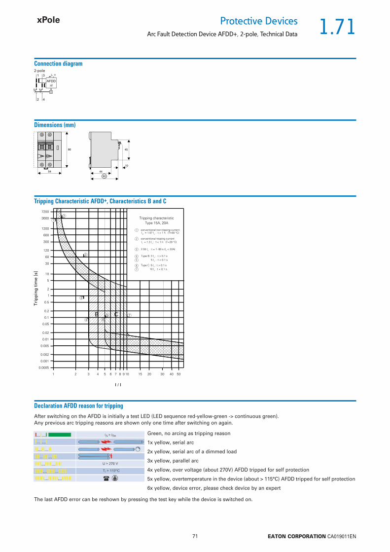
1.71
71 EATON CORPORATION CA019011EN
Protective DevicesArc Fault Detection Device AFDD+, 2-pole, Technical Data
Connection diagram2-pole
1
2
3
4
T
�I
AFDD
Dimensions (mm)
54
80 45
10
44
60
Tripping Characteristic AFDD+, Characteristics B and C
Declaration AFDD reason for tripping
After switching on the AFDD is initially a test LED (LED sequence red-yellow-green -> continuous green).Any previous arc tripping reasons are shown only one time after switching on again.
Green, no arcing as tripping reason
1x yellow, serial arc
2x yellow, serial arc of a dimmed load
3x yellow, parallel arc
4x yellow, over voltage (about 270V) AFDD tripped for self protection
5x yellow, overtemperature in the device (about > 115°C) AFDD tripped for self protection
6x yellow, device error, please check device by an expert
The last AFDD error can be reshown by pressing the test key while the device is switched on.
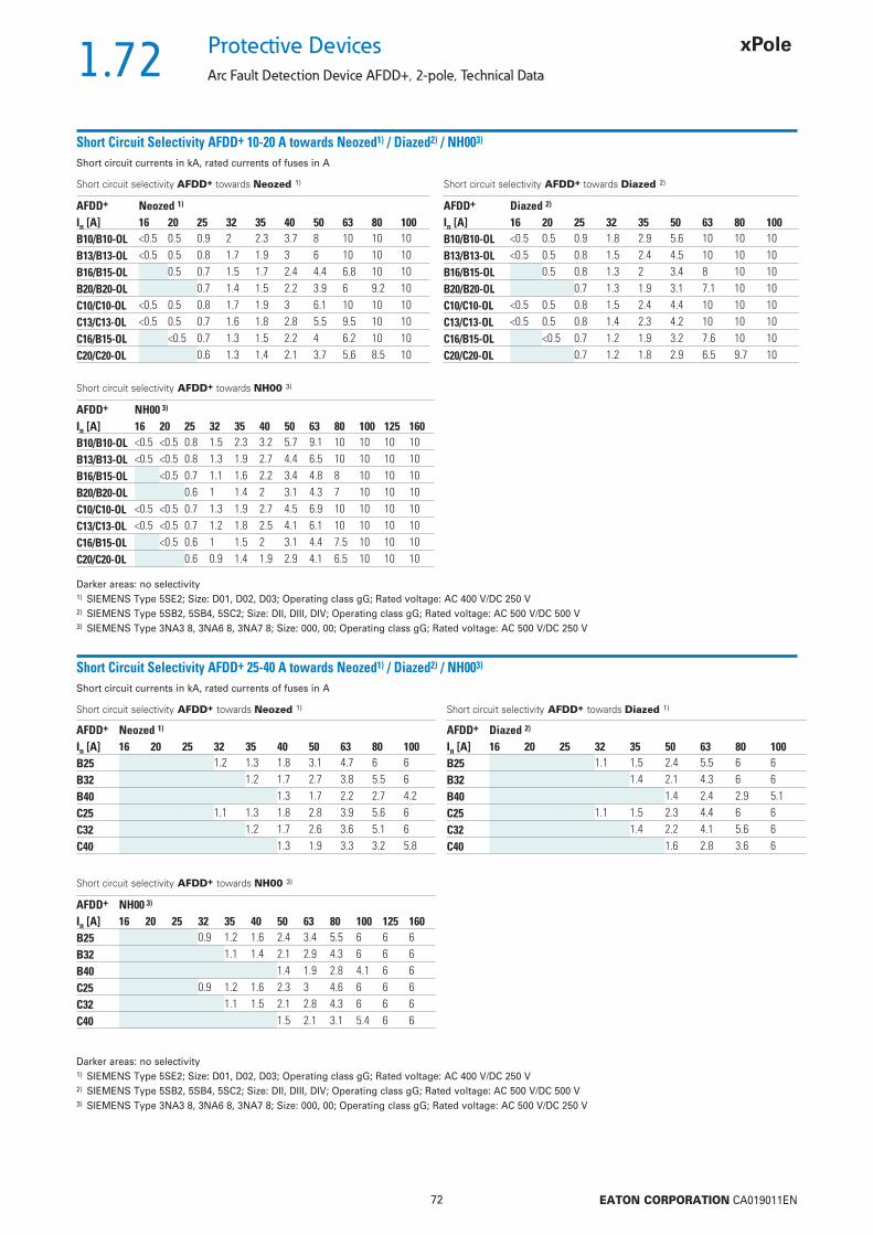
1.72
72 EATON CORPORATION CA019011EN
Protective Devices
Arc Fault Detection Device AFDD+, 2-pole, Technical Data
Short Circuit Selectivity AFDD+ 10-20 A towards Neozed1) / Diazed2) / NH003)
Short circuit currents in kA, rated currents of fuses in A
Short circuit selectivity AFDD+ towards Neozed 1)
Darker areas: no selectivity1) SIEMENS Type 5SE2; Size: D01, D02, D03; Operating class gG; Rated voltage: AC 400 V/DC 250 V2) SIEMENS Type 5SB2, 5SB4, 5SC2; Size: DII, DIII, DIV; Operating class gG; Rated voltage: AC 500 V/DC 500 V3) SIEMENS Type 3NA3 8, 3NA6 8, 3NA7 8; Size: 000, 00; Operating class gG; Rated voltage: AC 500 V/DC 250 V
Short circuit selectivity AFDD+ towards Diazed 2)
Short circuit selectivity AFDD+ towards NH00 3)
Short Circuit Selectivity AFDD+ 25-40 A towards Neozed1) / Diazed2) / NH003)
Short circuit currents in kA, rated currents of fuses in A
Short circuit selectivity AFDD+ towards Neozed 1) Short circuit selectivity AFDD+ towards Diazed 1)
Darker areas: no selectivity1) SIEMENS Type 5SE2; Size: D01, D02, D03; Operating class gG; Rated voltage: AC 400 V/DC 250 V2) SIEMENS Type 5SB2, 5SB4, 5SC2; Size: DII, DIII, DIV; Operating class gG; Rated voltage: AC 500 V/DC 500 V3) SIEMENS Type 3NA3 8, 3NA6 8, 3NA7 8; Size: 000, 00; Operating class gG; Rated voltage: AC 500 V/DC 250 V
Short circuit selectivity AFDD+ towards NH00 3)
AFDD+ Neozed 1)
In [A] 16 20 25 32 35 40 50 63 80 100B10/B10-OL <0.5 0.5 0.9 2 2.3 3.7 8 10 10 10B13/B13-OL <0.5 0.5 0.8 1.7 1.9 3 6 10 10 10B16/B15-OL 0.5 0.7 1.5 1.7 2.4 4.4 6.8 10 10B20/B20-OL 0.7 1.4 1.5 2.2 3.9 6 9.2 10C10/C10-OL <0.5 0.5 0.8 1.7 1.9 3 6.1 10 10 10C13/C13-OL <0.5 0.5 0.7 1.6 1.8 2.8 5.5 9.5 10 10C16/B15-OL <0.5 0.7 1.3 1.5 2.2 4 6.2 10 10C20/C20-OL 0.6 1.3 1.4 2.1 3.7 5.6 8.5 10
AFDD+ Diazed 2)
In [A] 16 20 25 32 35 50 63 80 100B10/B10-OL <0.5 0.5 0.9 1.8 2.9 5.6 10 10 10B13/B13-OL <0.5 0.5 0.8 1.5 2.4 4.5 10 10 10B16/B15-OL 0.5 0.8 1.3 2 3.4 8 10 10B20/B20-OL 0.7 1.3 1.9 3.1 7.1 10 10C10/C10-OL <0.5 0.5 0.8 1.5 2.4 4.4 10 10 10C13/C13-OL <0.5 0.5 0.8 1.4 2.3 4.2 10 10 10C16/B15-OL <0.5 0.7 1.2 1.9 3.2 7.6 10 10C20/C20-OL 0.7 1.2 1.8 2.9 6.5 9.7 10
AFDD+ NH00 3)
In [A] 16 20 25 32 35 40 50 63 80 100 125 160B10/B10-OL <0.5 <0.5 0.8 1.5 2.3 3.2 5.7 9.1 10 10 10 10B13/B13-OL <0.5 <0.5 0.8 1.3 1.9 2.7 4.4 6.5 10 10 10 10B16/B15-OL <0.5 0.7 1.1 1.6 2.2 3.4 4.8 8 10 10 10B20/B20-OL 0.6 1 1.4 2 3.1 4.3 7 10 10 10C10/C10-OL <0.5 <0.5 0.7 1.3 1.9 2.7 4.5 6.9 10 10 10 10C13/C13-OL <0.5 <0.5 0.7 1.2 1.8 2.5 4.1 6.1 10 10 10 10C16/B15-OL <0.5 0.6 1 1.5 2 3.1 4.4 7.5 10 10 10C20/C20-OL 0.6 0.9 1.4 1.9 2.9 4.1 6.5 10 10 10
AFDD+ Neozed 1)
In [A] 16 20 25 32 35 40 50 63 80 100B25 1.2 1.3 1.8 3.1 4.7 6 6B32 1.2 1.7 2.7 3.8 5.5 6B40 1.3 1.7 2.2 2.7 4.2C25 1.1 1.3 1.8 2.8 3.9 5.6 6C32 1.2 1.7 2.6 3.6 5.1 6C40 1.3 1.9 3.3 3.2 5.8
AFDD+ Diazed 2)
In [A] 16 20 25 32 35 50 63 80 100B25 1.1 1.5 2.4 5.5 6 6B32 1.4 2.1 4.3 6 6B40 1.4 2.4 2.9 5.1C25 1.1 1.5 2.3 4.4 6 6C32 1.4 2.2 4.1 5.6 6C40 1.6 2.8 3.6 6
AFDD+ NH00 3)
In [A] 16 20 25 32 35 40 50 63 80 100 125 160B25 0.9 1.2 1.6 2.4 3.4 5.5 6 6 6B32 1.1 1.4 2.1 2.9 4.3 6 6 6B40 1.4 1.9 2.8 4.1 6 6C25 0.9 1.2 1.6 2.3 3 4.6 6 6 6C32 1.1 1.5 2.1 2.8 4.3 6 6 6C40 1.5 2.1 3.1 5.4 6 6
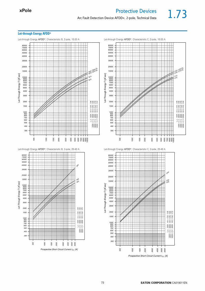
1.73
73 EATON CORPORATION CA019011EN
Protective DevicesArc Fault Detection Device AFDD+, 2-pole, Technical Data
Let-through Energy AFDD+
Let-through Energy AFDD+, Characteristic B, 2-pole, 10-20 A Let-through Energy AFDD+, Characteristic C, 2-pole, 10-20 A
Let-through Energy AFDD+, Characteristic B, 2-pole, 25-40 A Let-through Energy AFDD+, Characteristic C, 2-pole, 25-40 A
B20 / B20-OL
B10
B13
B16 / B15-OL
C20 / C20-OL
C10C13
C16 / C15-OL

1.74
74 EATON CORPORATION CA019011EN
Protective Devices
Combined RCD/MCB Devices PFL7, 1+N-pole
• Residual current device / miniature circuit
breaker combination, line voltage-independ-
ent
• Contact position indicator red - green
• Guide for secure terminal connection
• 3-position DIN rail clip, permits removal from
existing busbar system
• Comprehensive range of accessories can be
mounted subsequently
• Rated currents up to 40 A
• Tripping characteristics B, C
• Rated breaking capacity 10 kA
• Frost resistance
Description
SG61711

1.75
75 EATON CORPORATION CA019011EN
Protective DevicesCombined RCD/MCB Devices PFL7, 1+N-pole
Type G
10 kA, 1+N-poleSurge current-proof 3 kA, type G (ÖVE E 8601)
SG61711
13/0.03 PFL7-13/1N/B/003-G 263530 1/6016/0.03 PFL7-16/1N/B/003-G 263536 1/6020/0.03 PFL7-20/1N/B/003-G 263542 1/6025/0.03 PFL7-25/1N/B/003-G 263548 1/6032/0.03 PFL7-32/1N/B/003-G 263554 1/6040/0.03 PFL7-40/1N/B/003-G 263560 1/6013/0.3 PFL7-13/1N/B/03-G 165604 1/6016/0.3 PFL7-16/1N/B/03-G 165618 1/6020/0.3 PFL7-20/1N/B/03-G 165646 1/6025/0.3 PFL7-25/1N/B/03-G 165656 1/6032/0.3 PFL7-32/1N/B/03-G 165667 1/6040/0.3 PFL7-40/1N/B/03-G 165692 1/60
Characteristic B
In/In
(A)TypeDesignation
Article No. Units perpackage
SG61711
13/0.03 PFL7-13/1N/C/003-G 263533 1/6016/0.03 PFL7-16/1N/C/003-G 263539 1/6020/0.03 PFL7-20/1N/C/003-G 263545 1/6025/0.03 PFL7-25/1N/C/003-G 263551 1/6032/0.03 PFL7-32/1N/C/003-G 263557 1/6040/0.03 PFL7-40/1N/C/003-G 263563 1/6013/0.3 PFL7-13/1N/C/03-G 165611 1/6016/0.3 PFL7-16/1N/C/03-G 165625 1/6020/0.3 PFL7-20/1N/C/03-G 165651 1/6025/0.3 PFL7-25/1N/C/03-G 165661 1/6032/0.3 PFL7-32/1N/C/03-G 165672 1/6040/0.3 PFL7-40/1N/C/03-G 165697 1/60
Characteristic C

1.76
76 EATON CORPORATION CA019011EN
Protective Devices
Combined RCD/MCB Devices PFL7, 1+N-pole
Type A
10 kA, 1+N-poleConditionally surge current-proof 250 A, sensitive to residual pulsating DC, type A
SG61711
2/0.01 PFL7-2/1N/B/001-A 165633 1/604/0.01 PFL7-4/1N/B/001-A 165674 1/606/0.01 PFL7-6/1N/B/001-A 165700 1/6010/0.01 PFL7-10/1N/B/001-A 165587 1/6013/0.01 PFL7-13/1N/B/001-A 165599 1/6016/0.01 PFL7-16/1N/B/001-A 165613 1/602/0.03 PFL7-2/1N/B/003-A 165635 1/604/0.03 PFL7-4/1N/B/003-A 165676 1/606/0.03 PFL7-6/1N/B/003-A 263431 1/6010/0.03 PFL7-10/1N/B/003-A 263435 1/6013/0.03 PFL7-13/1N/B/003-A 263519 1/6016/0.03 PFL7-16/1N/B/003-A 263535 1/6020/0.03 PFL7-20/1N/B/003-A 263541 1/6025/0.03 PFL7-25/1N/B/003-A 263547 1/6032/0.03 PFL7-32/1N/B/003-A 263553 1/6040/0.03 PFL7-40/1N/B/003-A 263559 1/602/0.1 PFL7-2/1N/B/01-A 165637 1/604/0.1 PFL7-4/1N/B/01-A 165678 1/606/0.1 PFL7-6/1N/B/01-A 165702 1/6010/0.1 PFL7-10/1N/B/01-A 165589 1/6013/0.1 PFL7-13/1N/B/01-A 165601 1/6016/0.1 PFL7-16/1N/B/01-A 165615 1/6020/0.1 PFL7-20/1N/B/01-A 165643 1/6025/0.1 PFL7-25/1N/B/01-A 165653 1/6032/0.1 PFL7-32/1N/B/01-A 165664 1/6040/0.1 PFL7-40/1N/B/01-A 165689 1/602/0.3 PFL7-2/1N/B/03-A 165639 1/604/0.3 PFL7-4/1N/B/03-A 165680 1/606/0.3 PFL7-6/1N/B/03-A 165704 1/6010/0.3 PFL7-10/1N/B/03-A 165591 1/6013/0.3 PFL7-13/1N/B/03-A 165603 1/6016/0.3 PFL7-16/1N/B/03-A 165617 1/6020/0.3 PFL7-20/1N/B/03-A 165645 1/6025/0.3 PFL7-25/1N/B/03-A 165655 1/6032/0.3 PFL7-32/1N/B/03-A 165666 1/6040/0.3 PFL7-40/1N/B/03-A 165691 1/60
Characteristic B
In/In
(A)TypeDesignation
Article No. Units perpackage

1.77
77 EATON CORPORATION CA019011EN
Protective DevicesCombined RCD/MCB Devices PFL7, 1+N-pole
SG61711
2/0.01 PFL7-2/1N/C/001-A 165627 1/604/0.01 PFL7-4/1N/C/001-A 165682 1/606/0.01 PFL7-6/1N/C/001-A 165706 1/6010/0.01 PFL7-10/1N/C/001-A 165593 1/6013/0.01 PFL7-13/1N/C/001-A 165606 1/6016/0.01 PFL7-16/1N/C/001-A 165620 1/602/0.03 PFL7-2/1N/C/003-A 165628 1/604/0.03 PFL7-4/1N/C/003-A 165684 1/606/0.03 PFL7-6/1N/C/003-A 263515 1/6010/0.03 PFL7-10/1N/C/003-A 263517 1/6013/0.03 PFL7-13/1N/C/003-A 263532 1/6016/0.03 PFL7-16/1N/C/003-A 263538 1/6020/0.03 PFL7-20/1N/C/003-A 263544 1/6025/0.03 PFL7-25/1N/C/003-A 263550 1/6032/0.03 PFL7-32/1N/C/003-A 263556 1/6040/0.03 PFL7-40/1N/C/003-A 263562 1/602/0.1 PFL7-2/1N/C/01-A 165629 1/604/0.1 PFL7-4/1N/C/01-A 165685 1/606/0.1 PFL7-6/1N/C/01-A 165708 1/6010/0.1 PFL7-10/1N/C/01-A 165595 1/6013/0.1 PFL7-13/1N/C/01-A 165608 1/6016/0.1 PFL7-16/1N/C/01-A 165622 1/6020/0.1 PFL7-20/1N/C/01-A 165648 1/6025/0.1 PFL7-25/1N/C/01-A 165658 1/6032/0.1 PFL7-32/1N/C/01-A 165669 1/6040/0.1 PFL7-40/1N/C/01-A 165694 1/602/0.3 PFL7-2/1N/C/03-A 165631 1/604/0.3 PFL7-4/1N/C/03-A 165687 1/606/0.3 PFL7-6/1N/C/03-A 165710 1/6010/0.3 PFL7-10/1N/C/03-A 165597 1/6013/0.3 PFL7-13/1N/C/03-A 165610 1/6016/0.3 PFL7-16/1N/C/03-A 165624 1/6020/0.3 PFL7-20/1N/C/03-A 165650 1/6025/0.3 PFL7-25/1N/C/03-A 165660 1/6032/0.3 PFL7-32/1N/C/03-A 165671 1/6040/0.3 PFL7-40/1N/C/03-A 165696 1/60
Characteristic C
In/In
(A)TypeDesignation
Article No. Units perpackage

1.78
78 EATON CORPORATION CA019011EN
Protective Devices
Combined RCD/MCB Devices PFL7, 1+N-pole
Type AC
10 kA, 1+N-poleConditionally surge current-proof 250 A, type AC
SG61711
2/0.01 PFL7-2/1N/B/001 165634 1/604/0.01 PFL7-4/1N/B/001 165675 1/606/0.01 PFL7-6/1N/B/001 165701 1/6010/0.01 PFL7-10/1N/B/001 165588 1/6013/0.01 PFL7-13/1N/B/001 165600 1/6016/0.01 PFL7-16/1N/B/001 165614 1/602/0.03 PFL7-2/1N/B/003 165636 1/604/0.03 PFL7-4/1N/B/003 165677 1/606/0.03 PFL7-6/1N/B/003 263430 1/6010/0.03 PFL7-10/1N/B/003 263434 1/6013/0.03 PFL7-13/1N/B/003 263518 1/6016/0.03 PFL7-16/1N/B/003 263534 1/6020/0.03 PFL7-20/1N/B/003 263540 1/6025/0.03 PFL7-25/1N/B/003 263546 1/6032/0.03 PFL7-32/1N/B/003 263552 1/6040/0.03 PFL7-40/1N/B/003 263558 1/602/0.1 PFL7-2/1N/B/01 165638 1/604/0.1 PFL7-4/1N/B/01 165679 1/606/0.1 PFL7-6/1N/B/01 165703 1/6010/0.1 PFL7-10/1N/B/01 165590 1/6013/0.1 PFL7-13/1N/B/01 165602 1/6016/0.1 PFL7-16/1N/B/01 165616 1/6020/0.1 PFL7-20/1N/B/01 165644 1/6025/0.1 PFL7-25/1N/B/01 165654 1/6032/0.1 PFL7-32/1N/B/01 165665 1/6040/0.1 PFL7-40/1N/B/01 165690 1/602/0.3 PFL7-2/1N/B/03 165640 1/604/0.3 PFL7-4/1N/B/03 165681 1/606/0.3 PFL7-6/1N/B/03 165705 1/6010/0.3 PFL7-10/1N/B/03 165592 1/6013/0.3 PFL7-13/1N/B/03 165605 1/6016/0.3 PFL7-16/1N/B/03 165619 1/6020/0.3 PFL7-20/1N/B/03 165647 1/6025/0.3 PFL7-25/1N/B/03 165657 1/6032/0.3 PFL7-32/1N/B/03 165668 1/6040/0.3 PFL7-40/1N/B/03 165693 1/602/0.5 PFL7-2/1N/B/05 165641 1/60
Characteristic B
In/In
(A)TypeDesignation
Article No. Units perpackage
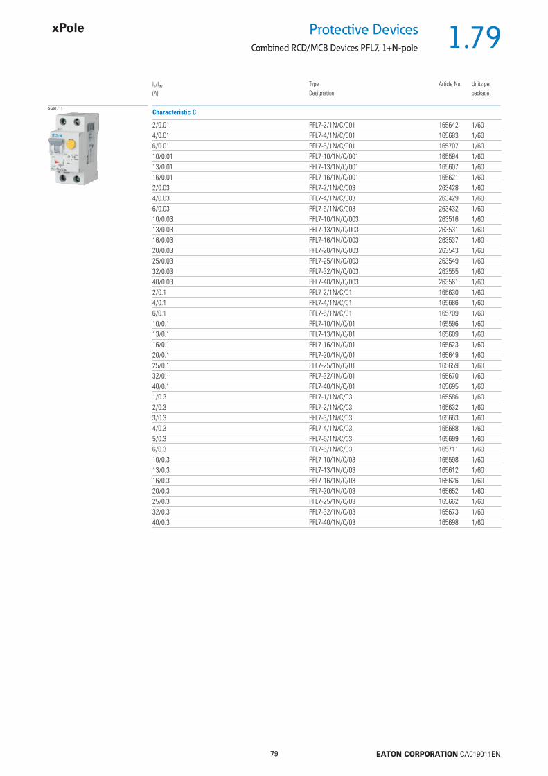
1.79
79 EATON CORPORATION CA019011EN
Protective DevicesCombined RCD/MCB Devices PFL7, 1+N-pole
SG61711
2/0.01 PFL7-2/1N/C/001 165642 1/604/0.01 PFL7-4/1N/C/001 165683 1/606/0.01 PFL7-6/1N/C/001 165707 1/6010/0.01 PFL7-10/1N/C/001 165594 1/6013/0.01 PFL7-13/1N/C/001 165607 1/6016/0.01 PFL7-16/1N/C/001 165621 1/602/0.03 PFL7-2/1N/C/003 263428 1/604/0.03 PFL7-4/1N/C/003 263429 1/606/0.03 PFL7-6/1N/C/003 263432 1/6010/0.03 PFL7-10/1N/C/003 263516 1/6013/0.03 PFL7-13/1N/C/003 263531 1/6016/0.03 PFL7-16/1N/C/003 263537 1/6020/0.03 PFL7-20/1N/C/003 263543 1/6025/0.03 PFL7-25/1N/C/003 263549 1/6032/0.03 PFL7-32/1N/C/003 263555 1/6040/0.03 PFL7-40/1N/C/003 263561 1/602/0.1 PFL7-2/1N/C/01 165630 1/604/0.1 PFL7-4/1N/C/01 165686 1/606/0.1 PFL7-6/1N/C/01 165709 1/6010/0.1 PFL7-10/1N/C/01 165596 1/6013/0.1 PFL7-13/1N/C/01 165609 1/6016/0.1 PFL7-16/1N/C/01 165623 1/6020/0.1 PFL7-20/1N/C/01 165649 1/6025/0.1 PFL7-25/1N/C/01 165659 1/6032/0.1 PFL7-32/1N/C/01 165670 1/6040/0.1 PFL7-40/1N/C/01 165695 1/601/0.3 PFL7-1/1N/C/03 165586 1/602/0.3 PFL7-2/1N/C/03 165632 1/603/0.3 PFL7-3/1N/C/03 165663 1/604/0.3 PFL7-4/1N/C/03 165688 1/605/0.3 PFL7-5/1N/C/03 165699 1/606/0.3 PFL7-6/1N/C/03 165711 1/6010/0.3 PFL7-10/1N/C/03 165598 1/6013/0.3 PFL7-13/1N/C/03 165612 1/6016/0.3 PFL7-16/1N/C/03 165626 1/6020/0.3 PFL7-20/1N/C/03 165652 1/6025/0.3 PFL7-25/1N/C/03 165662 1/6032/0.3 PFL7-32/1N/C/03 165673 1/6040/0.3 PFL7-40/1N/C/03 165698 1/60
Characteristic C
In/In
(A)TypeDesignation
Article No. Units perpackage

1.80
80 EATON CORPORATION CA019011EN
Protective Devices
Combined RCD/MCB Devices PFL7, 1+N-pole - Technical Data
Specifi cations | Combined RCD/MCB Devices PFL7, 1+N-pole
Description
• Combined RCD/MCB Devices• Line voltage-independent tripping• Twin-purpose terminal (lift/open-mouthed) above and below• Busbar positioning optionally above or below• Free terminal space despite installed busbar• Guide for secure terminal connection• Switching toggle (MCB component) in colour designating the rated current• Contact position indicator red - green• Comprehensive range of accessories can be mounted subsequently• The test key “T” must be pressed every 6 month. The system operator must
be informed of this obligation and his responsibility in a way that can be proven (self-adhesive RCD-label enclosed). The test intervall of 6 month is valid for residential and similar applications. Under all other conditions (e.g. damply or dusty environments), it’s recommended to test in shorter intervalls (e.g. monthly).
• Pressing the test key “T” serves the only purpose of function testing the residual current device (RCD). This test does not make earthing resistance measurement (RE), or proper checking of the earth conductor condition redundant, which must be performed separately.
• Type -A: Protects against special forms of residual pulsating DC which have have not been smoothed
• Type -G: 10 ms time delay in order to avoid unwanted tripping (e.g. duringthunderstorms).Compulsory in Austria for any circuit where personal injury or damage to prop-erty may occur in case of unwanted tripping (§12.1.6 ÖVE/ÖNORM E 8001-1).
Accessories:Auxiliary switch for subsequent installation ZP-IHK 286052
ZP-WHK 286053Tripping signal switch for subsequent installation ZP-NHK 248437Shunt trip release ZP-ASA/.. 248438, 248439Terminal cover cap KLV-TC-2 276240Additional terminal 35 mm2 Z-HA-EK/35 263960
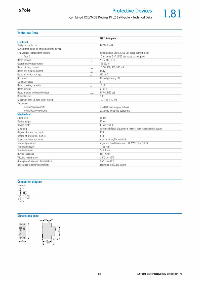
1.81
81 EATON CORPORATION CA019011EN
Protective DevicesCombined RCD/MCB Devices PFL7, 1+N-pole - Technical Data
Technical Data
PFL7, 1+N-poleElectricalDesign according toCurrent test marks as printed onto the device
IEC/EN 61009
Line voltage-independent tripping instantaneous 250 A (8/20 μs), surge current proofType G 10 ms delay 3 kA (8/20 μs), surge current proof
Rated voltage Ue 230 V AC; 50 HzOperational voltage range 196-253 VRated tripping current In 10, 30, 100, 300, 500 mARated non-tripping current Ino 0.5 In
Rated insulation voltage Ui 440 VACSensitivity AC and pulsating DCSelectivity class 3Rated breaking capacity Icn 10 kARated current 6 - 40 ARated impulse withstand voltage Uimp 6 kV (1.2/50 μs)Characteristic B, CMaximum back-up fuse (short circuit) 100 A gL (>10 kA)Endurance
electrical components 4,000 switching operationsmechanical components 20,000 switching operations
MechanicalFrame size 45 mmDevice height 80 mmDevice width 35 mm (2MU)Mounting 3-position DIN rail clip, permits removal from existing busbar systemDegree of protection, switch IP20Degree of protection, built-in IP40Upper and lower terminals open mouthed/lift terminalsTerminal protection fi nger and hand touch safe, DGUV VS3, EN 50274Terminal capacity 1 - 25 mm2
Terminal torque 2 - 2.4 NmBusbar thickness 0.8 - 2 mmTripping temperature -25°C to +40°CStorage- and transport temperature -35°C to +60°CResistance to climatic conditions according to IEC/EN 61009
Connection diagram1+N-pole
Dimensions (mm)
35
80 45
10
30,5
44
60
5,5 4,5
T
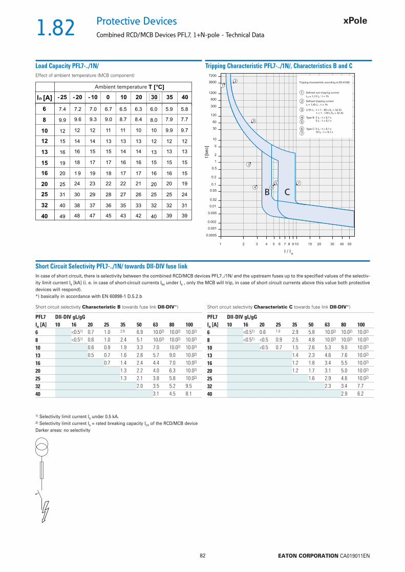
1.82
82 EATON CORPORATION CA019011EN
Protective Devices
Combined RCD/MCB Devices PFL7, 1+N-pole - Technical Data
Load Capacity PFL7-../1N/
Short Circuit Selectivity PFL7-../1N/ towards DII-DIV fuse linkIn case of short circuit, there is selectivity between the combined RCD/MCB devices PFL7../1N/ and the upstream fuses up to the specifi ed values of the selectiv-ity limit current Is [kA] (i. e. in case of short-circuit currents Iks under Is , only the MCB will trip, in case of short circuit currents above this value both protective devices will respond).*) basically in accordance with EN 60898-1 D.5.2.b
Short circuit selectivity Characteristic B towards fuse link DII-DIV*)
1) Selectivity limit current Is under 0.5 kA.2) Selectivity limit current Is = rated breaking capacity Icn of the RCD/MCB deviceDarker areas: no selectivity
Short circuit selectivity Characteristic C towards fuse link DII-DIV*)
Tripping Characteristic PFL7-../1N/, Characteristics B and C
PFL7 DII-DIV gL/gGIn [A] 10 16 20 25 35 50 63 80 1006 <0.51) 0.7 1.0 2.9 6.9 10.02) 10.02) 10.02)
8 <0.51) 0.6 1.0 2.4 5.1 10.02) 10.02) 10.02)
10 0.6 0.9 1.9 3.3 7.0 10.02) 10.02)
13 0.5 0.7 1.6 2.8 5.7 9.0 10.02)
16 0.7 1.4 2.4 4.4 7.0 10.02)
20 1.3 2.2 4.0 6.3 10.02)
25 1.3 2.1 3.8 5.8 10.02)
32 2.0 3.5 5.2 9.540 3.1 4.5 8.1
PFL7 DII-DIV gL/gGIn [A] 10 16 20 25 35 50 63 80 1006 <0.51) 0.6 1.0 2.9 5.8 10.02) 10.02) 10.02)
8 <0.51) <0.5 0.9 2.5 4.8 10.02) 10.02) 10.02)
10 <0.5 0.7 1.5 2.6 5.3 9.0 10.02)
13 1.4 2.3 4.6 7.6 10.02)
16 1.2 1.8 3.4 5.5 10.02)
20 1.2 1.7 3.1 5.0 10.02)
25 1.6 2.9 4.6 10.02)
32 2.3 3.4 7.740 2.9 6.2
Effect of ambient temperature (MCB component)Tripping characteristic according to EN 61009
Defi ned non-tripping current
Defi ned tripping current
Ambient temperature

1.83
83 EATON CORPORATION CA019011EN
Protective DevicesCombined RCD/MCB Devices PFL7, 1+N-pole - Technical Data
Short Circuit Selectivity PFL7-../1N/ towards D01-D03 fuse linkIn case of short circuit, there is selectivity between the combined RCD/MCB devices PFL7../1N/ and the upstream fuses up to the specifi ed values of the selectiv-ity limit current Is [kA] (i. e. in case of short-circuit currents Iks under Is , only the MCB will trip, in case of short circuit currents above this value both protective devices will respond).*) basically in accordance with EN 60898-1 D.5.2.b
Short circuit selectivity Characteristic B towards fuse link D01-D03*)
1) Selectivity limit current Is under 0.5 kA.2) Selectivity limit current Is = rated breaking capacity Icn of the RCD/MCB deviceDarker areas: no selectivity
Short circuit selectivity Characteristic C towards fuse link D01-D03*)
Short Circuit Selectivity PFL7-../1N/ towards NH-00 fuse linkIn case of short circuit, there is selectivity between the combined RCD/MCB devices PFL7../1N/ and the upstream fuses up to the specifi ed values of the selectiv-ity limit current Is [kA] (i. e. in case of short-circuit currents Iks under Is , only the MCB will trip, in case of short circuit currents above this value both protective devices will respond).*) basically in accordance with EN 60898-1 D.5.2.b
Short circuit selectivity Characteristic B towards fuse link NH-00*) Short circuit selectivity Characteristic C towards fuse link NH-00*)
PFL7 D01-D03 gL/gGIn [A] 10 16 20 25 35 50 63 80 1006 <0.51) 0.5 0.8 2.4 8.2 10.02) 10.02) 10.02)
8 0.6 0.8 2.0 6.0 10.02) 10.02) 10.02)
10 0.5 0.8 1.6 3.7 6.0 10.02) 10.02)
13 0.6 0.7 1.4 3.0 4.7 9.0 10.02)
16 0.6 1.2 2.6 3.9 7.0 10.02)
20 1.2 2.5 3.6 6.2 10.02)
25 1.2 2.3 3.3 5.7 10.02)
32 2.3 3.1 5.1 10.02)
40 2.8 4.5 9.5
PFL7 D01-D03 gL/gGIn [A] 10 16 20 25 35 50 63 80 1006 <0.51) <0.51) 0.8 2.3 6.5 10.02) 10.02) 10.02)
8 <0.5 0.7 2.1 5.5 9.5 10.02) 10.02)
10 <0.5 0.6 1.3 2.9 4.5 8.9 10.02)
13 1.2 2.5 3.9 7.6 10.02)
16 1.0 2.1 3.0 5.5 10.02)
20 1.0 2.0 2.7 5.0 10.02)
25 1.9 2.6 4.5 10.02)
32 2.1 3.4 10.02)
40 3.0 8.7
PFL7 NH-00 gL/gGIn [A] 16 20 25 32 35 40 50 63 80 100 125 1606 <0.51) 0.5 0.8 1.4 2.2 3.3 7.0 10.02) 10.02) 10.02) 10.02) 10.02)
10 <0.51) 0.7 0.9 1.5 2.1 3.4 4.3 7.3 10.02) 10.02) 10.02)
13 <0.51) 0.6 0.8 1.4 1.8 2.8 3.6 5.7 10.02) 10.02) 10.02)
16 0.6 0.7 1.2 1.5 2.4 3.0 4.5 10.02) 10.02) 10.02)
20 0.7 1.1 1.5 2.2 2.8 4.2 9.2 10.02) 10.02)
25 0.7 1.1 1.4 2.1 2.6 4.0 8.2 10.02) 10.02)
32 1.0 1.4 2.0 2.5 3.7 7.1 10.02) 10.02)
40 2.3 3.4 6.2 8.8 10.02)
PFL7 NH-00 gL/gGIn [A] 16 20 25 32 35 40 50 63 80 100 125 1606 <0.51) <0.51) 0.7 1.3 2.2 3.3 5.9 8.0 10.02) 10.02) 10.02) 10.02)
10 0.5 0.8 1.2 1.7 2.7 3.4 5.5 10.02) 10.02) 10.02)
13 1.1 1.5 2.3 2.9 4.7 10.02) 10.02) 10.02)
16 1.0 1.3 1.8 2.3 3.7 8.7 10.02) 10.02)
20 0.9 1.1 1.7 2.2 3.4 8.0 10.02) 10.02)
25 1.6 2.1 3.2 7.2 10.02) 10.02)
32 1.7 2.6 5.3 9.0 10.02)
40 2.4 4.5 7.5 10.0

1.84
84 EATON CORPORATION CA019011EN
Protective Devices
Combined RCD/MCB Devices PFL7, 1+N-pole - Technical Data
Let-through Energy PFL7-../1N/
Let-through Energy PFL7, Characteristic B, 1+N-pole Let-through Energy PFL7, Characteristic C, 1+N-pole
Prospective short-circuit current [A]
Let
thro
ugh
ener
gy I2
t [A
2 se
c]
Prospective short-circuit current [A]
Let
thro
ugh
ener
gy I2
t [A
2 se
c]

1.85
85 EATON CORPORATION CA019011EN
Protective DevicesCombined RCD/MCB Devices PFL6, 1+N-pole
• Economy series mainly for house installations
• Residual current device / miniature circuit
breaker combination, line voltage-independ-
ent
• Contact position indicator red - green
• Comprehensive range of accessories can be
mounted subsequently
• Rated currents up to 25 A
• Tripping characteristics B, C
• Rated breaking capacity 6 kA
• Frost resistance
Description
SG04414
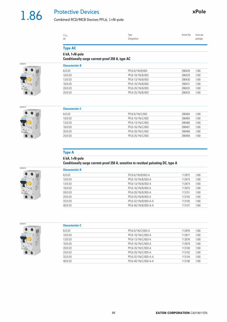
1.86
86 EATON CORPORATION CA019011EN
Protective Devices
Combined RCD/MCB Devices PFL6, 1+N-pole
Type AC
6 kA, 1+N-poleConditionally surge current-proof 250 A, type AC
SG04414
6/0.03 PFL6-6/1N/B/003 286428 1/6010/0.03 PFL6-10/1N/B/003 286429 1/6013/0.03 PFL6-13/1N/B/003 286430 1/6016/0.03 PFL6-16/1N/B/003 286431 1/6020/0.03 PFL6-20/1N/B/003 286432 1/6025/0.03 PFL6-25/1N/B/003 286433 1/60
Characteristic B
In/In
(A)TypeDesignation
Article No. Units perpackage
SG04414
6/0.03 PFL6-6/1N/C/003 286464 1/6010/0.03 PFL6-10/1N/C/003 286465 1/6013/0.03 PFL6-13/1N/C/003 286466 1/6016/0.03 PFL6-16/1N/C/003 286467 1/6020/0.03 PFL6-20/1N/C/003 286468 1/6025/0.03 PFL6-25/1N/C/003 286469 1/60
Characteristic C
Type A
6 kA, 1+N-poleConditionally surge current-proof 250 A, sensitive to residual pulsating DC, type A
SG04414
6/0.03 PFL6-6/1N/B/003-A 112872 1/6010/0.03 PFL6-10/1N/B/003-A 112873 1/6013/0.03 PFL6-13/1N/B/003-A 112874 1/6016/0.03 PFL6-16/1N/B/003-A 112875 1/6020/0.03 PFL6-20/1N/B/003-A 113101 1/6025/0.03 PFL6-25/1N/B/003-A 113103 1/6032/0.03 PFL6-32/1N/B/003-A-A 113105 1/6040/0.03 PFL6-40/1N/B/003-A-A 113107 1/60
Characteristic B
SG04414
6/0.03 PFL6-6/1N/C/003-A 112876 1/6010/0.03 PFL6-10/1N/C/003-A 112877 1/6013/0.03 PFL6-13/1N/C/003-A 112878 1/6016/0.03 PFL6-16/1N/C/003-A 112879 1/6020/0.03 PFL6-20/1N/C/003-A 113100 1/6025/0.03 PFL6-25/1N/C/003-A 113102 1/6032/0.03 PFL6-32/1N/C/003-A-A 113104 1/6040/0.03 PFL6-40/1N/C/003-A-A 113106 1/60
Characteristic C

1.87
87 EATON CORPORATION CA019011EN
Protective DevicesCombined RCD/MCB Devices PFL6, 1+N-pole - Technical Data
Specifi cations | Combined RCD/MCB Devices PFL6, 1+N-pole
Description
• Combined RCD/MCB Devices• Line voltage-independent tripping• Twin-purpose terminal (lift/open-mouthed) above and below• Busbar positioning optionally above or below• Free terminal space despite installed busbar• Guide for secure terminal connection• Contact position indicator red - green• Comprehensive range of accessories can be mounted subsequently• The test key “T” must be pressed every 6 month. The system operator must
be informed of this obligation and his responsibility in a way that can be proven (self-adhesive RCD-label enclosed). The test intervall of 6 month is valid for residential and similar applications. Under all other conditions (e.g. damply or dusty environments), it’s recommended to test in shorter intervalls (e.g. monthly).
• Pressing the test key “T” serves the only purpose of function testing the residual current device (RCD). This test does not make earthing resistance measurement (RE), or proper checking of the earth conductor condition redundant, which must be performed separately.
Accessories:Auxiliary switch for subsequent installation ZP-IHK 286052
ZP-WHK 286053Tripping signal switch for subsequent installation ZP-NHK 248437Shunt trip release ZP-ASA/.. 248438, 248439Terminal cover cap KLV-TC-2 276240Additional terminal 35 mm2 Z-HA-EK/35 263960
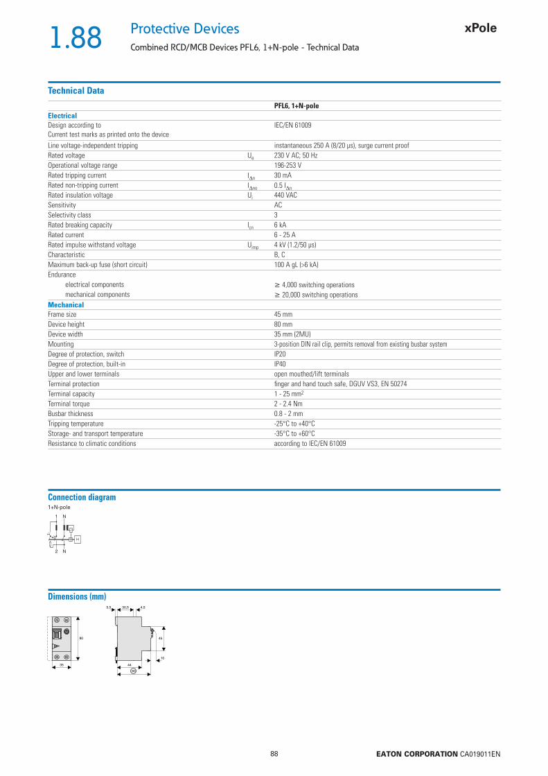
1.88
88 EATON CORPORATION CA019011EN
Protective Devices
Combined RCD/MCB Devices PFL6, 1+N-pole - Technical Data
Technical Data
PFL6, 1+N-poleElectricalDesign according toCurrent test marks as printed onto the device
IEC/EN 61009
Line voltage-independent tripping instantaneous 250 A (8/20 μs), surge current proofRated voltage Ue 230 V AC; 50 HzOperational voltage range 196-253 VRated tripping current In 30 mARated non-tripping current Ino 0.5 In
Rated insulation voltage Ui 440 VACSensitivity ACSelectivity class 3Rated breaking capacity Icn 6 kARated current 6 - 25 ARated impulse withstand voltage Uimp 4 kV (1.2/50 μs)Characteristic B, CMaximum back-up fuse (short circuit) 100 A gL (>6 kA)Endurance
electrical components 4,000 switching operationsmechanical components 20,000 switching operations
MechanicalFrame size 45 mmDevice height 80 mmDevice width 35 mm (2MU)Mounting 3-position DIN rail clip, permits removal from existing busbar systemDegree of protection, switch IP20Degree of protection, built-in IP40Upper and lower terminals open mouthed/lift terminalsTerminal protection fi nger and hand touch safe, DGUV VS3, EN 50274Terminal capacity 1 - 25 mm2
Terminal torque 2 - 2.4 NmBusbar thickness 0.8 - 2 mmTripping temperature -25°C to +40°CStorage- and transport temperature -35°C to +60°CResistance to climatic conditions according to IEC/EN 61009
Connection diagram1+N-pole
Dimensions (mm)
35
80 45
10
30,5
44
60
5,5 4,5
T
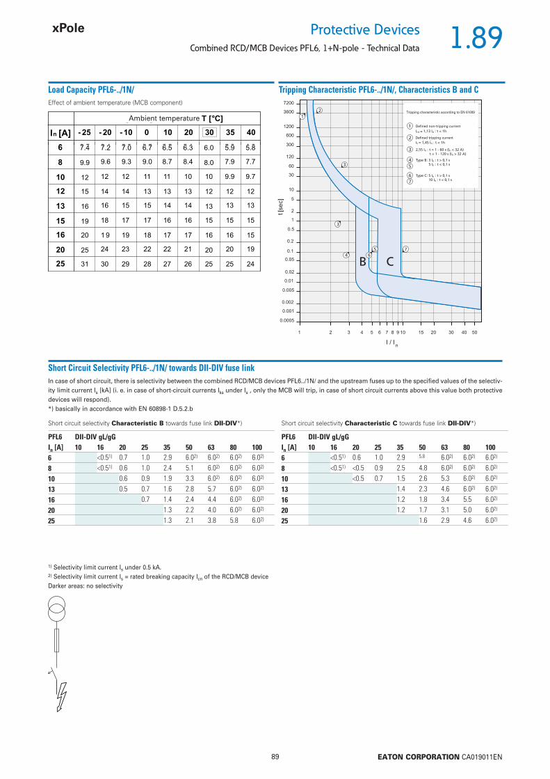
1.89
89 EATON CORPORATION CA019011EN
Protective DevicesCombined RCD/MCB Devices PFL6, 1+N-pole - Technical Data
Load Capacity PFL6-../1N/
Short Circuit Selectivity PFL6-../1N/ towards DII-DIV fuse linkIn case of short circuit, there is selectivity between the combined RCD/MCB devices PFL6../1N/ and the upstream fuses up to the specifi ed values of the selectiv-ity limit current Is [kA] (i. e. in case of short-circuit currents Iks under Is , only the MCB will trip, in case of short circuit currents above this value both protective devices will respond).*) basically in accordance with EN 60898-1 D.5.2.b
1) Selectivity limit current Is under 0.5 kA.2) Selectivity limit current Is = rated breaking capacity Icn of the RCD/MCB deviceDarker areas: no selectivity
Tripping Characteristic PFL6-../1N/, Characteristics B and C
Short circuit selectivity Characteristic B towards fuse link DII-DIV*) Short circuit selectivity Characteristic C towards fuse link DII-DIV*)
PFL6 DII-DIV gL/gGIn [A] 10 16 20 25 35 50 63 80 1006 <0.51) 0.7 1.0 2.9 6.02) 6.02) 6.02) 6.02)
8 <0.51) 0.6 1.0 2.4 5.1 6.02) 6.02) 6.02)
10 0.6 0.9 1.9 3.3 6.02) 6.02) 6.02)
13 0.5 0.7 1.6 2.8 5.7 6.02) 6.02)
16 0.7 1.4 2.4 4.4 6.02) 6.02)
20 1.3 2.2 4.0 6.02) 6.02)
25 1.3 2.1 3.8 5.8 6.02)
PFL6 DII-DIV gL/gGIn [A] 10 16 20 25 35 50 63 80 1006 <0.51) 0.6 1.0 2.9 5.8 6.02) 6.02) 6.02)
8 <0.51) <0.5 0.9 2.5 4.8 6.02) 6.02) 6.02)
10 <0.5 0.7 1.5 2.6 5.3 6.02) 6.02)
13 1.4 2.3 4.6 6.02) 6.02)
16 1.2 1.8 3.4 5.5 6.02)
20 1.2 1.7 3.1 5.0 6.02)
25 1.6 2.9 4.6 6.02)
Effect of ambient temperature (MCB component)
Ambient temperature Tripping characteristic according to EN 61009
Defi ned non-tripping current
Defi ned tripping current
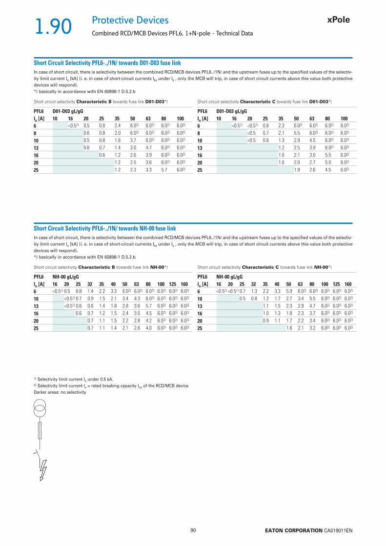
1.90
90 EATON CORPORATION CA019011EN
Protective Devices
Combined RCD/MCB Devices PFL6, 1+N-pole - Technical Data
Short Circuit Selectivity PFL6-../1N/ towards D01-D03 fuse linkIn case of short circuit, there is selectivity between the combined RCD/MCB devices PFL6../1N/ and the upstream fuses up to the specifi ed values of the selectiv-ity limit current Is [kA] (i. e. in case of short-circuit currents Iks under Is , only the MCB will trip, in case of short circuit currents above this value both protective devices will respond).*) basically in accordance with EN 60898-1 D.5.2.b
1) Selectivity limit current Is under 0.5 kA.2) Selectivity limit current Is = rated breaking capacity Icn of the RCD/MCB deviceDarker areas: no selectivity
Short Circuit Selectivity PFL6-../1N/ towards NH-00 fuse linkIn case of short circuit, there is selectivity between the combined RCD/MCB devices PFL6../1N/ and the upstream fuses up to the specifi ed values of the selectiv-ity limit current Is [kA] (i. e. in case of short-circuit currents Iks under Is , only the MCB will trip, in case of short circuit currents above this value both protective devices will respond).*) basically in accordance with EN 60898-1 D.5.2.b
Short circuit selectivity Characteristic B towards fuse link D01-D03*) Short circuit selectivity Characteristic C towards fuse link D01-D03*)
Short circuit selectivity Characteristic B towards fuse link NH-00*) Short circuit selectivity Characteristic C towards fuse link NH-00*)
PFL6 D01-D03 gL/gGIn [A] 10 16 20 25 35 50 63 80 1006 <0.51) 0.5 0.8 2.4 6.02) 6.02) 6.02) 6.02)
8 0.6 0.8 2.0 6.02) 6.02) 6.02) 6.02)
10 0.5 0.8 1.6 3.7 6.02) 6.02) 6.02)
13 0.6 0.7 1.4 3.0 4.7 6.02) 6.02)
16 0.6 1.2 2.6 3.9 6.02) 6.02)
20 1.2 2.5 3.6 6.02) 6.02)
25 1.2 2.3 3.3 5.7 6.02)
PFL6 D01-D03 gL/gGIn [A] 10 16 20 25 35 50 63 80 1006 <0.51) <0.51) 0.8 2.3 6.02) 6.02) 6.02) 6.02)
8 <0.5 0.7 2.1 5.5 6.02) 6.02) 6.02)
10 <0.5 0.6 1.3 2.9 4.5 6.02) 6.02)
13 1.2 2.5 3.9 6.02) 6.02)
16 1.0 2.1 3.0 5.5 6.02)
20 1.0 2.0 2.7 5.0 6.02)
25 1.9 2.6 4.5 6.02)
PFL6 NH-00 gL/gGIn [A] 16 20 25 32 35 40 50 63 80 100 125 1606 <0.51) 0.5 0.8 1.4 2.2 3.3 6.02) 6.02) 6.02) 6.02) 6.02) 6.02)
10 <0.51) 0.7 0.9 1.5 2.1 3.4 4.3 6.02) 6.02) 6.02) 6.02)
13 <0.51) 0.6 0.8 1.4 1.8 2.8 3.6 5.7 6.02) 6.02) 6.02)
16 0.6 0.7 1.2 1.5 2.4 3.0 4.5 6.02) 6.02) 6.02)
20 0.7 1.1 1.5 2.2 2.8 4.2 6.02) 6.02) 6.02)
25 0.7 1.1 1.4 2.1 2.6 4.0 6.02) 6.02) 6.02)
PFL6 NH-00 gL/gGIn [A] 16 20 25 32 35 40 50 63 80 100 125 1606 <0.51) <0.51) 0.7 1.3 2.2 3.3 5.9 6.02) 6.02) 6.02) 6.02) 6.02)
10 0.5 0.8 1.2 1.7 2.7 3.4 5.5 6.02) 6.02) 6.02)
13 1.1 1.5 2.3 2.9 4.7 6.02) 6.02) 6.02)
16 1.0 1.3 1.8 2.3 3.7 6.02) 6.02) 6.02)
20 0.9 1.1 1.7 2.2 3.4 6.02) 6.02) 6.02)
25 1.6 2.1 3.2 6.02) 6.02) 6.02)

1.91
91 EATON CORPORATION CA019011EN
Protective DevicesCombined RCD/MCB Devices PFL6, 1+N-pole - Technical Data
Let-through Energy PFL6-../1N/
Let-through Energy PFL6, Characteristic B, 1+N-pole Let-through Energy PFL6, Characteristic C, 1+N-pole
Prospective short-circuit current [A]
Let
thro
ugh
ener
gy I2
t [A
2 se
c]
Prospective short-circuit current [A]
Let
thro
ugh
ener
gy I2
t [A
2 se
c]

1.92
92 EATON CORPORATION CA019011EN
Protective Devices
RCBO Devices HNB xPole Home
• High-quality residual current device / minia-
ture circuit breaker combination, line voltage-
independent
• Contact position indicator red - green
• Comprehensive range of accessories can be
mounted subsequently
• 3-position DIN rail clip, permits removal from
existing busbar system
• Rated currents up to 25 A
• Tripping characteristics B, C
• Rated breaking capacity 6 kA
Description
sg00818_r
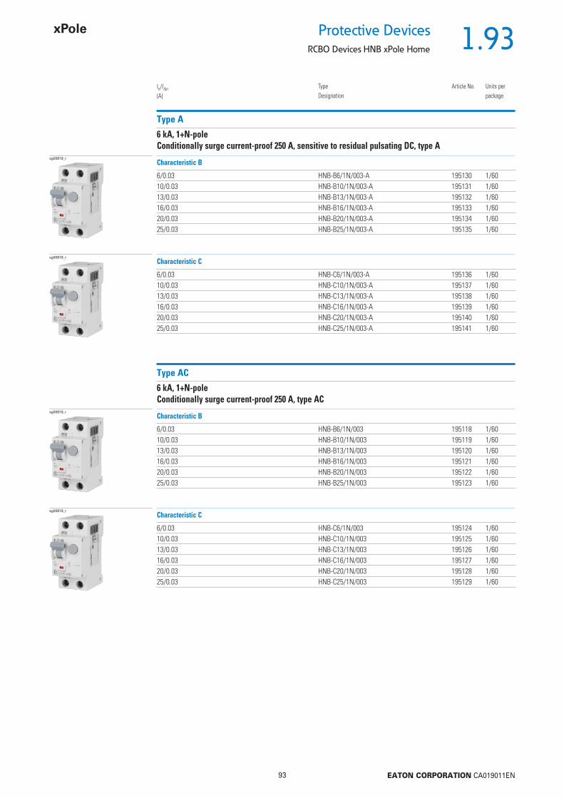
1.93
93 EATON CORPORATION CA019011EN
Protective DevicesRCBO Devices HNB xPole Home
Type A
6 kA, 1+N-poleConditionally surge current-proof 250 A, sensitive to residual pulsating DC, type A
In/In
(A)TypeDesignation
Article No. Units perpackage
6/0.03 HNB-B6/1N/003-A 195130 1/6010/0.03 HNB-B10/1N/003-A 195131 1/6013/0.03 HNB-B13/1N/003-A 195132 1/6016/0.03 HNB-B16/1N/003-A 195133 1/6020/0.03 HNB-B20/1N/003-A 195134 1/6025/0.03 HNB-B25/1N/003-A 195135 1/60
Characteristic B
6/0.03 HNB-C6/1N/003-A 195136 1/6010/0.03 HNB-C10/1N/003-A 195137 1/6013/0.03 HNB-C13/1N/003-A 195138 1/6016/0.03 HNB-C16/1N/003-A 195139 1/6020/0.03 HNB-C20/1N/003-A 195140 1/6025/0.03 HNB-C25/1N/003-A 195141 1/60
Characteristic C
Type AC
6 kA, 1+N-poleConditionally surge current-proof 250 A, type AC
6/0.03 HNB-B6/1N/003 195118 1/6010/0.03 HNB-B10/1N/003 195119 1/6013/0.03 HNB-B13/1N/003 195120 1/6016/0.03 HNB-B16/1N/003 195121 1/6020/0.03 HNB-B20/1N/003 195122 1/6025/0.03 HNB-B25/1N/003 195123 1/60
Characteristic B
6/0.03 HNB-C6/1N/003 195124 1/6010/0.03 HNB-C10/1N/003 195125 1/6013/0.03 HNB-C13/1N/003 195126 1/6016/0.03 HNB-C16/1N/003 195127 1/6020/0.03 HNB-C20/1N/003 195128 1/6025/0.03 HNB-C25/1N/003 195129 1/60
Characteristic C
sg00818_r
sg00818_r
sg00818_r
sg00818_r
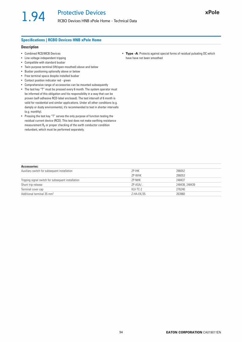
1.94
94 EATON CORPORATION CA019011EN
Protective Devices
RCBO Devices HNB xPole Home - Technical Data
Specifi cations | RCBO Devices HNB xPole Home
Description
• Combined RCD/MCB Devices• Line voltage-independent tripping• Compatible with standard busbar• Twin-purpose terminal (lift/open-mouthed) above and below• Busbar positioning optionally above or below• Free terminal space despite installed busbar• Contact position indicator red - green• Comprehensive range of accessories can be mounted subsequently• The test key “T” must be pressed every 6 month. The system operator must
be informed of this obligation and his responsibility in a way that can be proven (self-adhesive RCD-label enclosed). The test intervall of 6 month is valid for residential and similar applications. Under all other conditions (e.g. damply or dusty environments), it’s recommended to test in shorter intervalls (e.g. monthly).
• Pressing the test key “T” serves the only purpose of function testing the residual current device (RCD). This test does not make earthing resistance measurement RE or proper checking of the earth conductor condition redundant, which must be performed separately.
• Type -A: Protects against special forms of residual pulsating DC which have have not been smoothed
Accessories:Auxiliary switch for subsequent installation ZP-IHK 286052
ZP-WHK 286053Tripping signal switch for subsequent installation ZP-NHK 248437Shunt trip release ZP-ASA/.. 248438, 248439Terminal cover cap KLV-TC-2 276240Additional terminal 35 mm2 Z-HA-EK/35 263960
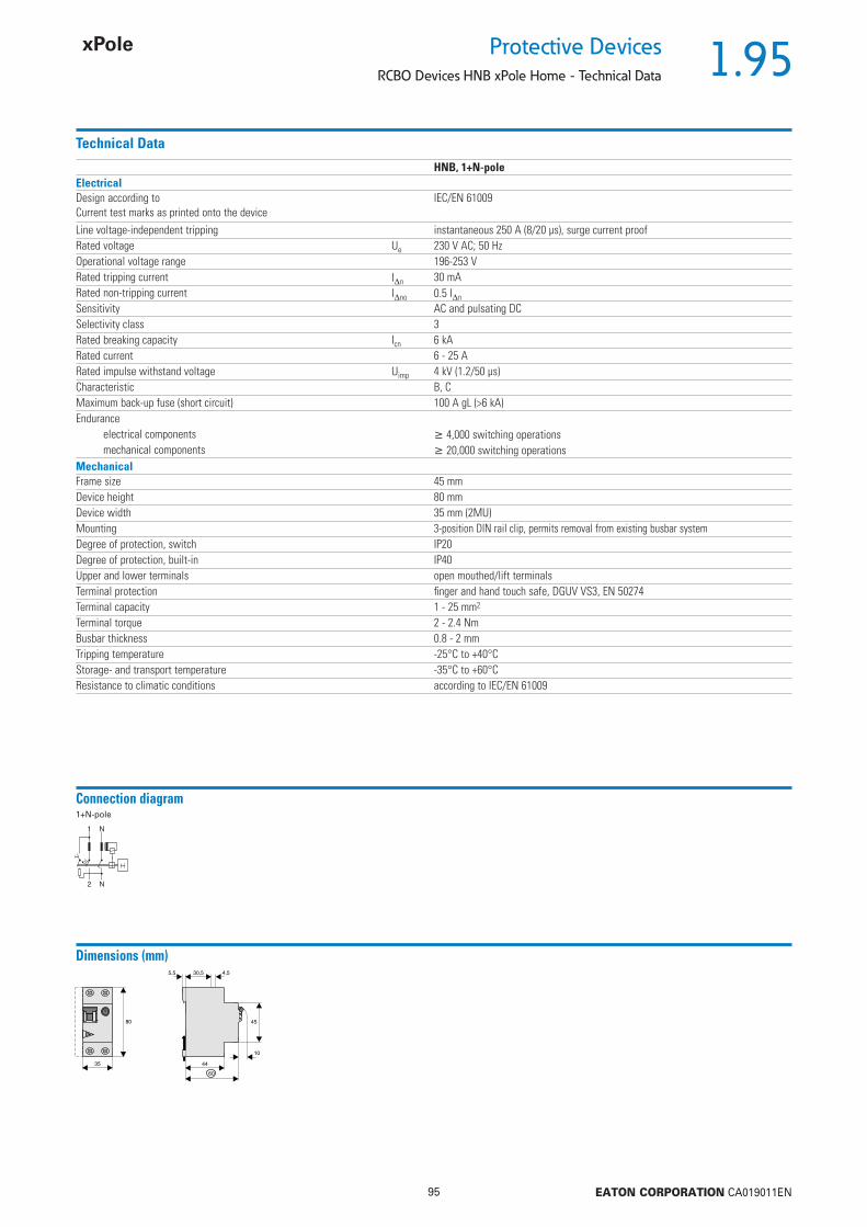
1.95
95 EATON CORPORATION CA019011EN
Protective DevicesRCBO Devices HNB xPole Home - Technical Data
Technical Data
HNB, 1+N-poleElectricalDesign according toCurrent test marks as printed onto the device
IEC/EN 61009
Line voltage-independent tripping instantaneous 250 A (8/20 μs), surge current proofRated voltage Ue 230 V AC; 50 HzOperational voltage range 196-253 VRated tripping current In 30 mARated non-tripping current Ino 0.5 In
Sensitivity AC and pulsating DCSelectivity class 3Rated breaking capacity Icn 6 kARated current 6 - 25 ARated impulse withstand voltage Uimp 4 kV (1.2/50 μs)Characteristic B, CMaximum back-up fuse (short circuit) 100 A gL (>6 kA)Endurance
electrical components 4,000 switching operationsmechanical components 20,000 switching operations
MechanicalFrame size 45 mmDevice height 80 mmDevice width 35 mm (2MU)Mounting 3-position DIN rail clip, permits removal from existing busbar systemDegree of protection, switch IP20Degree of protection, built-in IP40Upper and lower terminals open mouthed/lift terminalsTerminal protection fi nger and hand touch safe, DGUV VS3, EN 50274Terminal capacity 1 - 25 mm2
Terminal torque 2 - 2.4 NmBusbar thickness 0.8 - 2 mmTripping temperature -25°C to +40°CStorage- and transport temperature -35°C to +60°CResistance to climatic conditions according to IEC/EN 61009
Connection diagram1+N-pole
Dimensions (mm)
35
80 45
10
30,5
44
60
5,5 4,5
T

1.96
96 EATON CORPORATION CA019011EN
Protective Devices
RCBO Devices HNB xPole Home - Technical Data
Load Capacity HNB
Short Circuit Selectivity HNB towards DII-DIV fuse linkIn case of short circuit, there is selectivity between the combined RCD/MCB devices HNB and the upstream fuses up to the specifi ed values of the selectivity limit current Is [kA] (i. e. in case of short-circuit currents Iks under Is , only the MCB will trip, in case of short circuit currents above this value both protective devices will respond).*) basically in accordance with EN 60898-1 D.5.2.b
Short circuit selectivity Characteristic B towards fuse link DII-DIV*)
1) Selectivity limit current Is under 0.5 kA.2) Selectivity limit current Is = rated breaking capacity Icn of the RCD/MCB deviceDarker areas: no selectivity
Short circuit selectivity Characteristic C towards fuse link DII-DIV*)
Tripping Characteristic HNB, Characteristics B and C
HNB DII-DIV gL/gGIn [A] 10 16 20 25 35 50 63 80 1006 <0.51) 0.7 1.0 2.9 6.02) 6.02) 6.02) 6.02)
10 0.6 0.9 1.9 3.3 6.02) 6.02) 6.02)
13 0.5 0.7 1.6 2.8 5.7 6.02) 6.02)
16 0.7 1.4 2.4 4.4 6.02) 6.02)
20 1.3 2.2 4.0 6.02) 6.02)
25 1.3 2.1 3.8 5.8 6.02)
HNB DII-DIV gL/gGIn [A] 10 16 20 25 35 50 63 80 1006 <0.51) 0.6 1.0 2.9 5.8 6.02) 6.02) 6.02)
10 <0.5 0.7 1.5 2.6 5.3 6.02) 6.02)
13 1.4 2.3 4.6 6.02) 6.02)
16 1.2 1.8 3.4 5.5 6.02)
20 1.2 1.7 3.1 5.0 6.02)
25 1.6 2.9 4.6 6.02)
Effect of ambient temperature (MCB component)Tripping characteristic according to EN 61009
Defi ned non-tripping current
Defi ned tripping current
Ambient temperature T [˚C]
In [A] -25 -20 -10 0 10 20 30 35 40
6 7.4 7.2 7.0 6.7 6.5 6.3 6.0 5.9 5.8
10 12 12 12 11 11 10 10 9.9 9.7
13 16 16 15 15 14 14 13 13 13
16 20 19 19 18 17 17 16 16 15
20 25 24 23 22 22 21 20 20 19
25 31 30 29 28 27 26 25 25 24
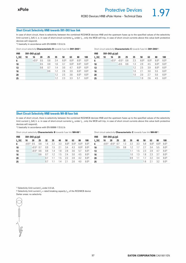
1.97
97 EATON CORPORATION CA019011EN
Protective DevicesRCBO Devices HNB xPole Home - Technical Data
Short Circuit Selectivity HNB towards D01-D03 fuse linkIn case of short circuit, there is selectivity between the combined RCD/MCB devices HNB and the upstream fuses up to the specifi ed values of the selectivity limit current Is [kA] (i. e. in case of short-circuit currents Iks under Is , only the MCB will trip, in case of short circuit currents above this value both protective devices will respond).*) basically in accordance with EN 60898-1 D.5.2.b
Short circuit selectivity Characteristic B towards fuse link D01-D03*)
1) Selectivity limit current Is under 0.5 kA.2) Selectivity limit current Is = rated breaking capacity Icn of the RCD/MCB deviceDarker areas: no selectivity
Short circuit selectivity Characteristic C towards fuse link D01-D03*)
Short Circuit Selectivity HNB towards NH-00 fuse linkIn case of short circuit, there is selectivity between the combined RCD/MCB devices HNB and the upstream fuses up to the specifi ed values of the selectivity limit current Is [kA] (i. e. in case of short-circuit currents Iks under Is , only the MCB will trip, in case of short circuit currents above this value both protective devices will respond).*) basically in accordance with EN 60898-1 D.5.2.b
Short circuit selectivity Characteristic B towards fuse link NH-00*) Short circuit selectivity Characteristic C towards fuse link NH-00*)
HNB D01-D03 gL/gGIn [A] 10 16 20 25 35 50 63 80 1006 <0.51) 0.5 0.8 2.4 6.02) 6.02) 6.02) 6.02)
10 0.5 0.8 1.6 3.7 6.02) 6.02) 6.02)
13 0.6 0.7 1.4 3.0 4.7 6.02) 6.02)
16 0.6 1.2 2.6 3.9 6.02) 6.02)
20 1.2 2.5 3.6 6.02) 6.02)
25 1.2 2.3 3.3 5.7 6.02)
HNB D01-D03 gL/gGIn [A] 10 16 20 25 35 50 63 80 1006 <0.51) <0.51) 0.8 2.3 6.02) 6.02) 6.02) 6.02)
10 <0.5 0.6 1.3 2.9 4.5 6.02) 6.02)
13 1.2 2.5 3.9 6.02) 6.02)
16 1.0 2.1 3.0 5.5 6.02)
20 1.0 2.0 2.7 5.0 6.02)
25 1.9 2.6 4.5 6.02)
HNB D01-D03 gL/gGIn [A] 16 20 25 32 35 40 50 63 80 1006 <0.51) 0.5 0.8 1.4 2.2 3.3 6.02) 6.02) 6.02) 6.02)
10 <0.51) 0.7 0.9 1.5 2.1 3.4 4.3 6.02) 6.02)
13 <0.51) 0.6 0.8 1.4 1.8 2.8 3.6 5.7 6.02)
16 0.6 0.7 1.2 1.5 2.4 3.0 4.5 6.02)
20 0.7 1.1 1.5 2.2 2.8 4.2 6.02)
25 0.7 1.1 1.4 2.1 2.6 4.0 6.02)
HNB D01-D03 gL/gGIn [A] 16 20 25 32 35 40 50 63 80 1006 <0.51) <0.51) 0.7 1.3 2.2 3.3 5.9 6.02) 6.02) 6.02)
10 0.5 0.8 1.2 1.7 2.7 3.4 5.5 6.02)
13 1.1 1.5 2.3 2.9 4.7 6.02)
16 1.0 1.3 1.8 2.3 3.7 6.02)
20 0.9 1.1 1.7 2.2 3.4 6.02)
25 1.6 2.1 3.2 6.02)
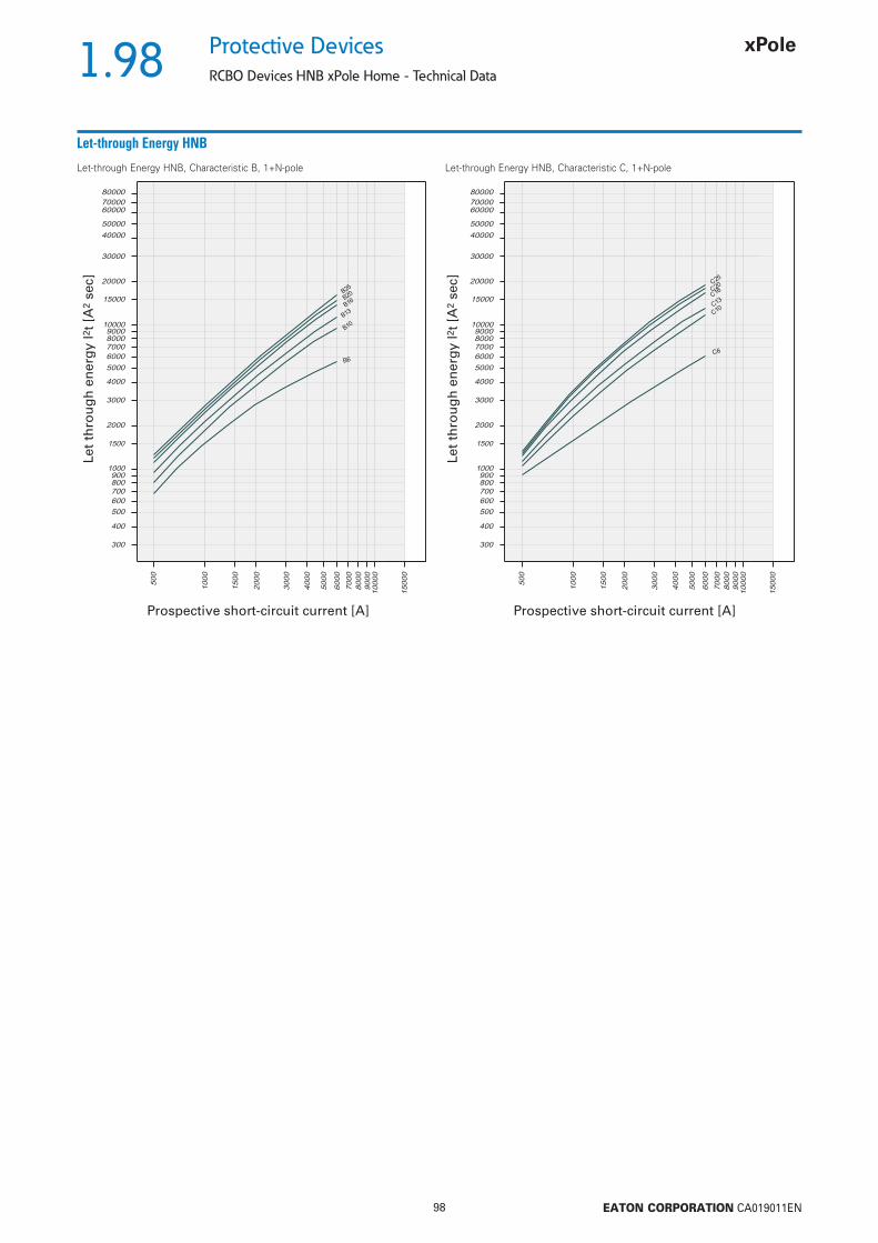
1.98
98 EATON CORPORATION CA019011EN
Protective Devices
RCBO Devices HNB xPole Home - Technical Data
Let-through Energy HNB
Let-through Energy HNB, Characteristic B, 1+N-pole Let-through Energy HNB, Characteristic C, 1+N-pole
Let
thro
ug
h e
ner
gy
I2t
[A2
sec]
Prospective short-circuit current [A] Prospective short-circuit current [A]
Let
thro
ug
h e
ner
gy
I2t
[A2
sec]

1.99
99 EATON CORPORATION CA019011EN
Protective DevicesCombined RCD/MCB Devices mRB6, mRB4, 3+N-pole
• High-quality residual current device / minia-
ture circuit breaker combination, line voltage-
independent
• Contact position indicator red - green
• Fault current tripping indicator white - blue
• Guide for secure terminal connection
• 3-position DIN rail clip, permits removal from
existing busbar system
• Comprehensive range of accessories can be
mounted subsequently
• Wide variety of rated tripping currents
• Rated currents up to 25 A
• Tripping characteristics B, C, D
• Rated breaking capacity 6 kA or 4.5 kA
Description
SG14211
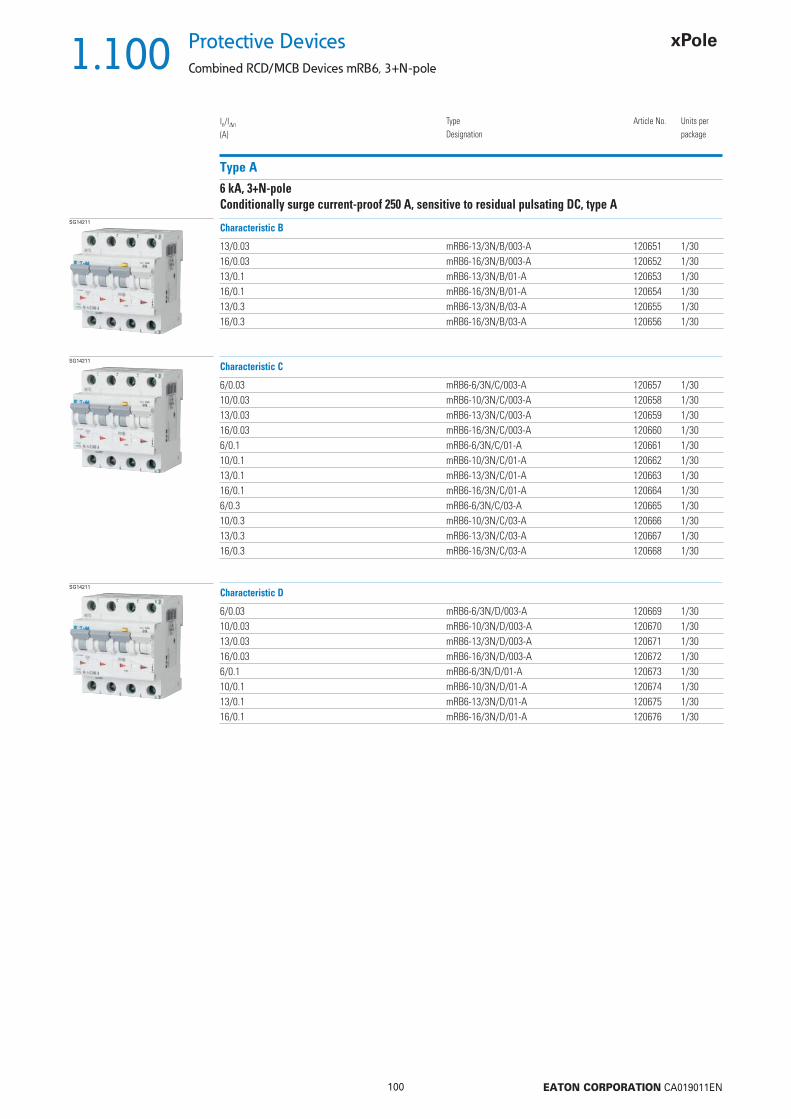
1.100
100 EATON CORPORATION CA019011EN
Protective Devices
Combined RCD/MCB Devices mRB6, 3+N-pole
In/In
(A)TypeDesignation
Article No. Units perpackage
Type A
6 kA, 3+N-poleConditionally surge current-proof 250 A, sensitive to residual pulsating DC, type A
SG14211
13/0.03 mRB6-13/3N/B/003-A 120651 1/3016/0.03 mRB6-16/3N/B/003-A 120652 1/3013/0.1 mRB6-13/3N/B/01-A 120653 1/3016/0.1 mRB6-16/3N/B/01-A 120654 1/3013/0.3 mRB6-13/3N/B/03-A 120655 1/3016/0.3 mRB6-16/3N/B/03-A 120656 1/30
Characteristic B
SG14211
6/0.03 mRB6-6/3N/C/003-A 120657 1/3010/0.03 mRB6-10/3N/C/003-A 120658 1/3013/0.03 mRB6-13/3N/C/003-A 120659 1/3016/0.03 mRB6-16/3N/C/003-A 120660 1/306/0.1 mRB6-6/3N/C/01-A 120661 1/3010/0.1 mRB6-10/3N/C/01-A 120662 1/3013/0.1 mRB6-13/3N/C/01-A 120663 1/3016/0.1 mRB6-16/3N/C/01-A 120664 1/306/0.3 mRB6-6/3N/C/03-A 120665 1/3010/0.3 mRB6-10/3N/C/03-A 120666 1/3013/0.3 mRB6-13/3N/C/03-A 120667 1/3016/0.3 mRB6-16/3N/C/03-A 120668 1/30
Characteristic C
SG14211
6/0.03 mRB6-6/3N/D/003-A 120669 1/3010/0.03 mRB6-10/3N/D/003-A 120670 1/3013/0.03 mRB6-13/3N/D/003-A 120671 1/3016/0.03 mRB6-16/3N/D/003-A 120672 1/306/0.1 mRB6-6/3N/D/01-A 120673 1/3010/0.1 mRB6-10/3N/D/01-A 120674 1/3013/0.1 mRB6-13/3N/D/01-A 120675 1/3016/0.1 mRB6-16/3N/D/01-A 120676 1/30
Characteristic D

1.101
101 EATON CORPORATION CA019011EN
Protective DevicesCombined RCD/MCB Devices mRB4, 3+N-pole
In/In
(A)TypeDesignation
Article No. Units perpackage
Type A
4.5 kA, 3+N-poleConditionally surge current-proof 250 A, sensitive to residual pulsating DC, type A
SG14211
20/0.03 mRB4-20/3N/C/003-A 120677 1/3025/0.03 mRB4-25/3N/C/003-A 120678 1/3032/0.03 mRB4-32/3N/C/003-A 167508 1/3020/0.1 mRB4-20/3N/C/01-A 120679 1/3025/0.1 mRB4-25/3N/C/01-A 120680 1/3032/0.1 mRB4-32/3N/C/01-A 167509 1/3020/0.3 mRB4-20/3N/C/03-A 120681 1/3025/0.3 mRB4-25/3N/C/03-A 120682 1/3032/0.3 mRB4-32/3N/C/03-A 167510 1/30
Characteristic C
SG14211
20/0.03 mRB4-20/3N/D/003-A 120683 1/3020/0.1 mRB4-20/3N/D/01-A 120684 1/30
Characteristic D

1.102
102 EATON CORPORATION CA019011EN
Protective Devices
Combined RCD/MCB Devices mRB., 3+N-pole - Technical Data
Specifi cations | Combined RCD/MCB Devices mRB., 3+N-pole
Description
• Combined RCD/MCB Devices• Line voltage-independent tripping• Compatible with standard busbar• Twin-purpose terminal (lift/open-mouthed) above and below• Busbar positioning optionally above or below• Free terminal space despite installed busbar• Guide for secure terminal connection• Switching toggle (MCB component) in colour designating the rated current• Contact position indicator red - green• Fault current tripping indicator white - blue• Comprehensive range of accessories can be mounted subsequently• The test key “T” must be pressed every 6 month. The system operator must
be informed of this obligation and his responsibility in a way that can be proven (self-adhesive RCD-label enclosed). The test intervall of 6 month is valid for residential and similar applications. Under all other conditions (e.g. damply or dusty environments), it’s recommended to test in shorter intervalls (e.g. monthly).
• Pressing the test key “T” serves the only purpose of function testing the residual current device (RCD). This test does not make earthing resistance measurement (RE), or proper checking of the earth conductor condition redundant, which must be performed separately.
• Type -A: Protects against special forms of residual pulsating DC which have have not been smoothed
Accessories:Tripping signal switch for subsequent installation ZP-IHK 286052
ZP-NHK 248437ZP-WHK 286053
Shunt trip release ZP-ASA/.. 248438, 248439
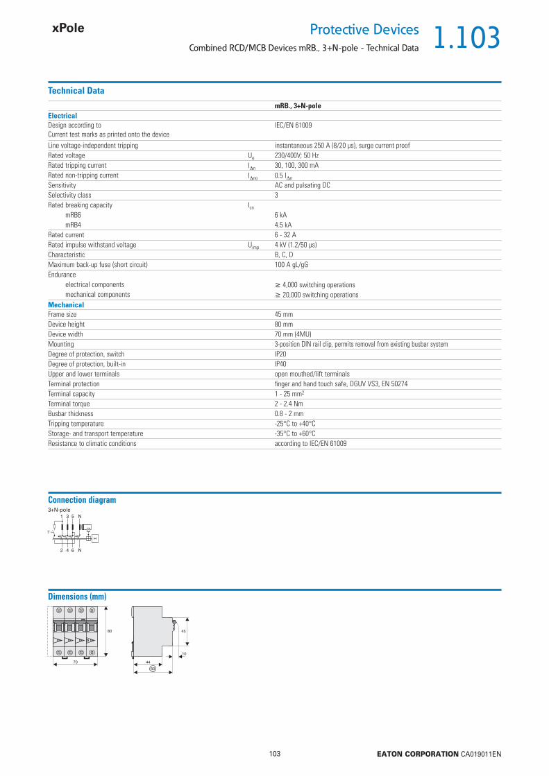
1.103
103 EATON CORPORATION CA019011EN
Protective DevicesCombined RCD/MCB Devices mRB., 3+N-pole - Technical Data
Technical Data
mRB., 3+N-poleElectricalDesign according toCurrent test marks as printed onto the device
IEC/EN 61009
Line voltage-independent tripping instantaneous 250 A (8/20 μs), surge current proofRated voltage Ue 230/400V; 50 HzRated tripping current In 30, 100, 300 mARated non-tripping current Ino 0.5 In
Sensitivity AC and pulsating DCSelectivity class 3Rated breaking capacity Icn
mRB6 6 kAmRB4 4.5 kA
Rated current 6 - 32 ARated impulse withstand voltage Uimp 4 kV (1.2/50 μs)Characteristic B, C, DMaximum back-up fuse (short circuit) 100 A gL/gGEndurance
electrical components 4,000 switching operationsmechanical components 20,000 switching operations
MechanicalFrame size 45 mmDevice height 80 mmDevice width 70 mm (4MU)Mounting 3-position DIN rail clip, permits removal from existing busbar systemDegree of protection, switch IP20Degree of protection, built-in IP40Upper and lower terminals open mouthed/lift terminalsTerminal protection fi nger and hand touch safe, DGUV VS3, EN 50274Terminal capacity 1 - 25 mm2
Terminal torque 2 - 2.4 NmBusbar thickness 0.8 - 2 mmTripping temperature -25°C to +40°CStorage- and transport temperature -35°C to +60°CResistance to climatic conditions according to IEC/EN 61009
Connection diagram3+N-pole
Dimensions (mm)

1.104
104 EATON CORPORATION CA019011EN
Protective Devices
Combined RCD/MCB Devices mRB., 3+N-pole - Technical Data
Tripping Characteristic mRB., Characteristics B, C and D
Tripping Characteristic acc. to EN 61009
conventional non-tripping current
conventional tripping current
Back-up Protection between mRB. and NZM1Short circuit currents in kA.
Ue = 415V: Icn (mRB4) = 4.5 kA (acc. to IEC/EN 61009)Ue = 415V: Icn (mRB6) = 6 kA (acc. to IEC/EN 61009)Ue = 400/415V: Icu (NZMB1) = 25 kA (acc. to IEC/EN 60947-2)Ue = 400/415V: Icu (NZMC1) = 36 kA (acc. to IEC/EN 60947-2)Ue = 400/415V: Icu (NZMN1) = 50 kA (acc. to IEC/EN 60947-2)Ue = 400/415V: Icu (NZMH1) = 100 kA (acc. to IEC/EN 60947-2)
Back-up Protection between mRB. and NZM2Short circuit currents in kA.
Ue = 415V: Icn (mRB4) = 4.5 kA (acc. to IEC/EN 61009)Ue = 415V: Icn (mRB6) = 6 kA (acc. to IEC/EN 61009)Ue = 400/415V: Icu (NZMB2) = 25 kA (acc. to IEC/EN 60947-2)Ue = 400/415V: Icu (NZMC2) = 36 kA (acc. to IEC/EN 60947-2)Ue = 400/415V: Icu (NZMN2) = 50 kA (acc. to IEC/EN 60947-2)Ue = 400/415V: Icu (NZMH2) = 150 kA (acc. to IEC/EN 60947-2)
Back-up Protection between mRB. and PLSM-OV63Short circuit currents in kA.
Ue = 415V: Icn (mRB4) = 4.5 kA (acc. to IEC/EN 61009)Ue = 415V: Icn (mRB6) = 6 kA (acc. to IEC/EN 61009)Ue = 400V: Icu (PLSM-OV) = 10 kA (acc. to IEC/EN 60947-2)
Back-up Protection between mRB. and PLHT-OV80Short circuit currents in kA.
Ue = 415V: Icn (mRB4) = 4.5 kA (acc. to IEC/EN 61009)Ue = 415V: Icn (mRB6) = 6 kA (acc. to IEC/EN 61009)Ue = 400V: Icu (PLHT-80) = 20 kA (acc. to IEC/EN 60947-2)
mRB4/mRB6 NZMB1(C1)(N1)(H1)-A…Ue = 415 VB C D
6 - 20 2010 - 20 2013 20 20 2016 20 20 2020 - 20 2025 - 20 -
mRB4/mRB6 NZMB2(C2)(N2)(H2)-A…Ue = 415 VB C D
6 - 20 2010 - 20 2013 20 20 2016 20 20 2020 - 20 2025 - 20 -
mRB4/mRB6 PLSM-OV63Ue = 400 VB C D
6 - 10 1010 - 10 1013 10 10 1016 10 10 1020 - 10 1025 - 10 -
mRB4/mRB6 PLHT-OV80Ue = 400 VB C D
6 - 20 2010 - 20 2013 20 20 2016 20 20 2020 - 20 2025 - 20 -

1.105
105 EATON CORPORATION CA019011EN
Protective DevicesMiniature Circuit Breakers PL7
• High-quality miniature circuit breakers for
commercial and residential applications
• Contact position indicator red - green
• Guide for secure terminal connection
• 3-position DIN rail clip, permits removal from
existing busbar system
• Comprehensive range of accessories can be
mounted subsequently
• Rated currents up to 63 A
• Tripping characteristics B, C, D
• Rated breaking capacity 10 kA according to
IEC/EN 60898-1
Description
SG06511
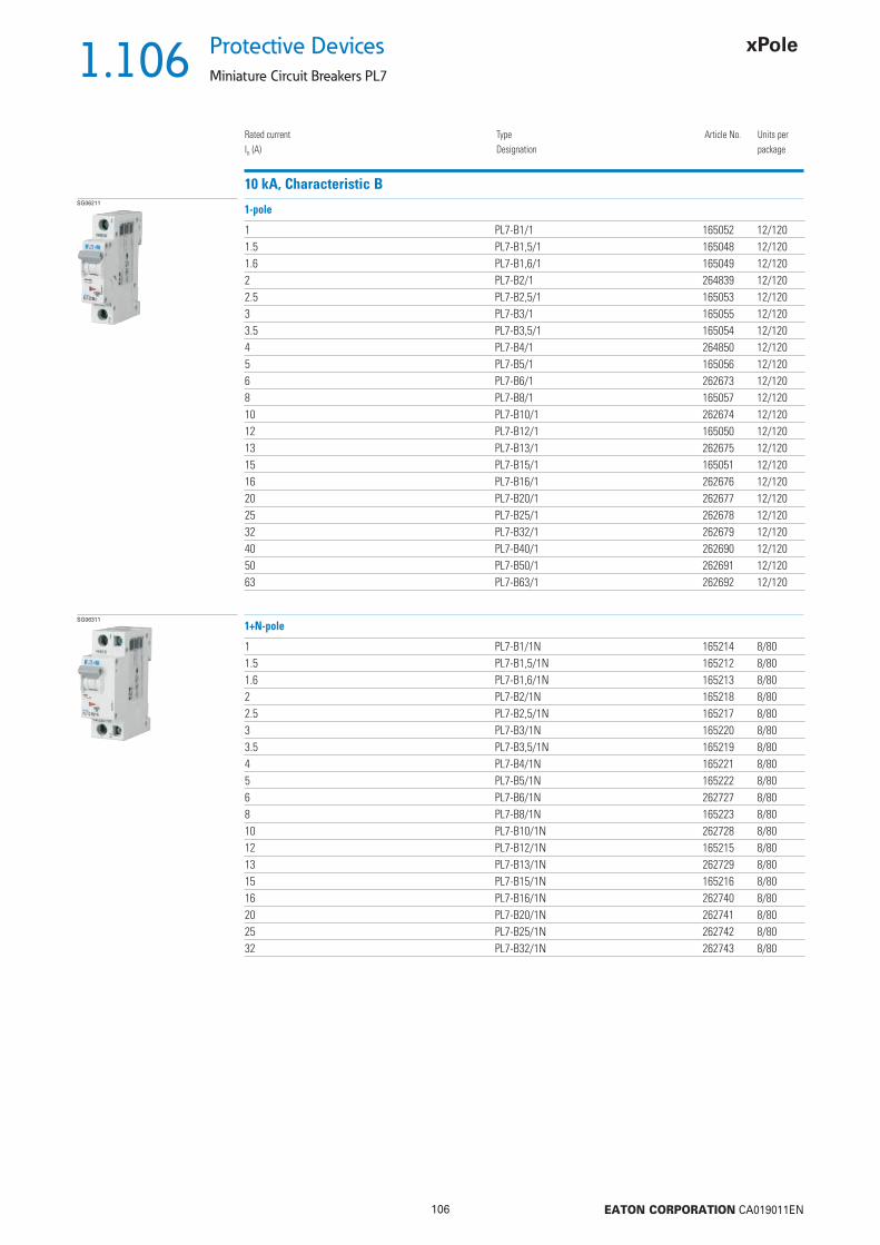
1.106
106 EATON CORPORATION CA019011EN
Protective Devices
Miniature Circuit Breakers PL7
Rated currentIn (A)
TypeDesignation
Article No. Units perpackage
10 kA, Characteristic BSG06211
1 PL7-B1/1 165052 12/1201.5 PL7-B1,5/1 165048 12/1201.6 PL7-B1,6/1 165049 12/1202 PL7-B2/1 264839 12/1202.5 PL7-B2,5/1 165053 12/1203 PL7-B3/1 165055 12/1203.5 PL7-B3,5/1 165054 12/1204 PL7-B4/1 264850 12/1205 PL7-B5/1 165056 12/1206 PL7-B6/1 262673 12/1208 PL7-B8/1 165057 12/12010 PL7-B10/1 262674 12/12012 PL7-B12/1 165050 12/12013 PL7-B13/1 262675 12/12015 PL7-B15/1 165051 12/12016 PL7-B16/1 262676 12/12020 PL7-B20/1 262677 12/12025 PL7-B25/1 262678 12/12032 PL7-B32/1 262679 12/12040 PL7-B40/1 262690 12/12050 PL7-B50/1 262691 12/12063 PL7-B63/1 262692 12/120
1-pole
SG06311
1 PL7-B1/1N 165214 8/801.5 PL7-B1,5/1N 165212 8/801.6 PL7-B1,6/1N 165213 8/802 PL7-B2/1N 165218 8/802.5 PL7-B2,5/1N 165217 8/803 PL7-B3/1N 165220 8/803.5 PL7-B3,5/1N 165219 8/804 PL7-B4/1N 165221 8/805 PL7-B5/1N 165222 8/806 PL7-B6/1N 262727 8/808 PL7-B8/1N 165223 8/8010 PL7-B10/1N 262728 8/8012 PL7-B12/1N 165215 8/8013 PL7-B13/1N 262729 8/8015 PL7-B15/1N 165216 8/8016 PL7-B16/1N 262740 8/8020 PL7-B20/1N 262741 8/8025 PL7-B25/1N 262742 8/8032 PL7-B32/1N 262743 8/80
1+N-pole

1.107
107 EATON CORPORATION CA019011EN
Protective DevicesMiniature Circuit Breakers PL7
Rated currentIn (A)
TypeDesignation
Article No. Units perpackage
SG06411
1 PL7-B1/2 165079 6/601.5 PL7-B1,5/2 165077 6/601.6 PL7-B1,6/2 165078 6/602 PL7-B2/2 165083 6/602.5 PL7-B2,5/2 165082 6/603 PL7-B3/2 165085 6/603.5 PL7-B3,5/2 165084 6/604 PL7-B4/2 165086 6/605 PL7-B5/2 165087 6/606 PL7-B6/2 262761 6/608 PL7-B8/2 165088 6/6010 PL7-B10/2 262762 6/6012 PL7-B12/2 165080 6/6013 PL7-B13/2 262764 6/6015 PL7-B15/2 165081 6/6016 PL7-B16/2 262765 6/6020 PL7-B20/2 262766 6/6025 PL7-B25/2 262767 6/6032 PL7-B32/2 262768 6/6040 PL7-B40/2 262769 6/6050 PL7-B50/2 263350 6/6063 PL7-B63/2 263351 6/60
2-pole
SG06511
1 PL7-B1/3 165112 4/401.5 PL7-B1,5/3 165110 4/401.6 PL7-B1,6/3 165111 4/402 PL7-B2/3 165116 4/402.5 PL7-B2,5/3 165115 4/403 PL7-B3/3 165118 4/403.5 PL7-B3,5/3 165117 4/404 PL7-B4/3 116709 4/405 PL7-B5/3 165119 4/406 PL7-B6/3 263386 4/408 PL7-B8/3 165120 4/4010 PL7-B10/3 263387 4/4012 PL7-B12/3 165113 4/4013 PL7-B13/3 263388 4/4015 PL7-B15/3 165114 4/4016 PL7-B16/3 263389 4/4020 PL7-B20/3 263390 4/4025 PL7-B25/3 263391 4/4032 PL7-B32/3 263392 4/4040 PL7-B40/3 263393 4/4050 PL7-B50/3 263400 4/4063 PL7-B63/3 263401 4/40
3-pole

1.108
108 EATON CORPORATION CA019011EN
Protective Devices
Miniature Circuit Breakers PL7
Rated currentIn (A)
TypeDesignation
Article No. Units perpackage
SG06711
1 PL7-B1/3N 165251 3/301.5 PL7-B1,5/3N 165249 3/301.6 PL7-B1,6/3N 165250 3/302 PL7-B2/3N 165255 3/302.5 PL7-B2,5/3N 165254 3/303 PL7-B3/3N 165257 3/303.5 PL7-B3,5/3N 165256 3/304 PL7-B4/3N 165258 3/305 PL7-B5/3N 165259 3/306 PL7-B6/3N 263982 3/308 PL7-B8/3N 165260 3/3010 PL7-B10/3N 263983 3/3012 PL7-B12/3N 165252 3/3013 PL7-B13/3N 263984 3/3015 PL7-B15/3N 165253 3/3016 PL7-B16/3N 263985 3/3020 PL7-B20/3N 263986 3/3025 PL7-B25/3N 263987 3/3032 PL7-B32/3N 263988 3/3040 PL7-B40/3N 263989 3/3050 PL7-B50/3N 263990 3/3063 PL7-B63/3N 263991 3/30
3+N-pole
SG06611
1 PL7-B1/4 165146 3/301.5 PL7-B1,5/4 165144 3/301.6 PL7-B1,6/4 165145 3/302 PL7-B2/4 165153 3/302.5 PL7-B2,5/4 165152 3/303 PL7-B3/4 165157 3/303.5 PL7-B3,5/4 165156 3/304 PL7-B4/4 165159 3/305 PL7-B5/4 165161 3/306 PL7-B6/4 165163 3/308 PL7-B8/4 165165 3/3010 PL7-B10/4 165147 3/3012 PL7-B12/4 165148 3/3013 PL7-B13/4 165149 3/3015 PL7-B15/4 165150 3/3016 PL7-B16/4 165151 3/3020 PL7-B20/4 165154 3/3025 PL7-B25/4 165155 3/3032 PL7-B32/4 165158 3/3040 PL7-B40/4 165160 3/3050 PL7-B50/4 165162 3/3063 PL7-B63/4 165164 3/30
4-pole

1.109
109 EATON CORPORATION CA019011EN
Protective DevicesMiniature Circuit Breakers PL7
Rated currentIn (A)
TypeDesignation
Article No. Units perpackage
10 kA, Characteristic CSG06211
0.16 PL7-C0.16/1 262693 12/1200.25 PL7-C0,25/1 262694 12/1200.5 PL7-C0,5/1 262695 12/1200.75 PL7-C0,75/1 262696 12/1201 PL7-C1/1 262697 12/1201.5 PL7-C1,5/1 165058 12/1201.6 PL7-C1,6/1 262698 12/1202 PL7-C2/1 262699 12/1202.5 PL7-C2,5/1 165061 12/1203 PL7-C3/1 165063 12/1203.5 PL7-C3,5/1 165062 12/1204 PL7-C4/1 262700 12/1205 PL7-C5/1 165064 12/1206 PL7-C6/1 262701 12/1208 PL7-C8/1 165065 12/12010 PL7-C10/1 262702 12/12012 PL7-C12/1 165059 12/12013 PL7-C13/1 262703 12/12015 PL7-C15/1 165060 12/12016 PL7-C16/1 262704 12/12020 PL7-C20/1 262705 12/12025 PL7-C25/1 262706 12/12032 PL7-C32/1 262707 12/12040 PL7-C40/1 262708 12/12050 PL7-C50/1 262709 12/12063 PL7-C63/1 262710 12/120
1-pole
SG06311
0.16 PL7-C0.16/1N 165224 8/800.25 PL7-C0,25/1N 165225 8/800.5 PL7-C0,5/1N 165226 8/800.75 PL7-C0,75/1N 165227 8/801 PL7-C1/1N 165230 8/801.5 PL7-C1,5/1N 165228 8/801.6 PL7-C1,6/1N 165229 8/802 PL7-C2/1N 262744 8/802.5 PL7-C2,5/1N 165233 8/803 PL7-C3/1N 165235 8/803.5 PL7-C3,5/1N 165234 8/804 PL7-C4/1N 262745 8/805 PL7-C5/1N 165236 8/806 PL7-C6/1N 262746 8/808 PL7-C8/1N 165237 8/8010 PL7-C10/1N 262747 8/8012 PL7-C12/1N 165231 8/8013 PL7-C13/1N 262748 8/8015 PL7-C15/1N 165232 8/8016 PL7-C16/1N 262749 8/8020 PL7-C20/1N 262750 8/8025 PL7-C25/1N 262751 8/8032 PL7-C32/1N 262752 8/80
1+N-pole

1.110
110 EATON CORPORATION CA019011EN
Protective Devices
Miniature Circuit Breakers PL7
Rated currentIn (A)
TypeDesignation
Article No. Units perpackage
SG06411
0.16 PL7-C0.16/2 165089 6/600.25 PL7-C0,25/2 165090 6/600.5 PL7-C0,5/2 263352 6/600.75 PL7-C0,75/2 165091 6/601 PL7-C1/2 263353 6/601.5 PL7-C1,5/2 165092 6/601.6 PL7-C1,6/2 165093 6/602 PL7-C2/2 263354 6/602.5 PL7-C2,5/2 165096 6/603 PL7-C3/2 165098 6/603.5 PL7-C3,5/2 165097 6/604 PL7-C4/2 263355 6/605 PL7-C5/2 165099 6/606 PL7-C6/2 263356 6/608 PL7-C8/2 165100 6/6010 PL7-C10/2 263357 6/6012 PL7-C12/2 165094 6/6013 PL7-C13/2 263358 6/6015 PL7-C15/2 165095 6/6016 PL7-C16/2 263359 6/6020 PL7-C20/2 263360 6/6025 PL7-C25/2 263361 6/6032 PL7-C32/2 263362 6/6040 PL7-C40/2 263363 6/6050 PL7-C50/2 263364 6/6063 PL7-C63/2 263365 6/60
2-pole
SG06511
0.16 PL7-C0.16/3 165121 4/400.25 PL7-C0,25/3 165122 4/400.5 PL7-C0,5/3 263402 4/400.75 PL7-C0,75/3 165123 4/401 PL7-C1/3 263403 4/401.5 PL7-C1,5/3 165124 4/401.6 PL7-C1,6/3 165125 4/402 PL7-C2/3 263404 4/402.5 PL7-C2,5/3 165128 4/403 PL7-C3/3 165130 4/403.5 PL7-C3,5/3 165129 4/404 PL7-C4/3 263405 4/405 PL7-C5/3 165131 4/406 PL7-C6/3 263406 4/408 PL7-C8/3 165132 4/4010 PL7-C10/3 263407 4/4012 PL7-C12/3 165126 4/4013 PL7-C13/3 263408 4/4015 PL7-C15/3 165127 4/4016 PL7-C16/3 263409 4/4020 PL7-C20/3 263410 4/4025 PL7-C25/3 263411 4/4032 PL7-C32/3 263412 4/4040 PL7-C40/3 263413 4/4050 PL7-C50/3 263414 4/4063 PL7-C63/3 263415 4/40
3-pole

1.111
111 EATON CORPORATION CA019011EN
Protective DevicesMiniature Circuit Breakers PL7
Rated currentIn (A)
TypeDesignation
Article No. Units perpackage
SG06711
0.16 PL7-C0.16/3N 165261 3/300.25 PL7-C0,25/3N 165262 3/300.5 PL7-C0,5/3N 165263 3/300.75 PL7-C0,75/3N 165264 3/301 PL7-C1/3N 165267 3/301.5 PL7-C1,5/3N 165265 3/301.6 PL7-C1,6/3N 165266 3/302 PL7-C2/3N 165271 3/302.5 PL7-C2,5/3N 165270 3/303 PL7-C3/3N 165273 3/303.5 PL7-C3,5/3N 165272 3/304 PL7-C4/3N 165274 3/305 PL7-C5/3N 165275 3/306 PL7-C6/3N 263992 3/308 PL7-C8/3N 165276 3/3010 PL7-C10/3N 263993 3/3012 PL7-C12/3N 165268 3/3013 PL7-C13/3N 263994 3/3015 PL7-C15/3N 165269 3/3016 PL7-C16/3N 263995 3/3020 PL7-C20/3N 263996 3/3025 PL7-C25/3N 263997 3/3032 PL7-C32/3N 263998 3/3040 PL7-C40/3N 263999 3/3050 PL7-C50/3N 264000 3/3063 PL7-C63/3N 264001 3/30
3+N-pole
SG06611
0.16 PL7-C0.16/4 165166 3/300.25 PL7-C0,25/4 165167 3/300.5 PL7-C0,5/4 165168 3/300.75 PL7-C0,75/4 165169 3/301 PL7-C1/4 165172 3/301.5 PL7-C1,5/4 165170 3/301.6 PL7-C1,6/4 165171 3/302 PL7-C2/4 165178 3/302.5 PL7-C2,5/4 165177 3/303 PL7-C3/4 165182 3/303.5 PL7-C3,5/4 165181 3/304 PL7-C4/4 165184 3/305 PL7-C5/4 165186 3/306 PL7-C6/4 165188 3/308 PL7-C8/4 165190 3/3010 PL7-C10/4 165173 3/3012 PL7-C12/4 165174 3/3013 PL7-C13/4 165175 3/3015 PL7-C15/4 165176 3/3016 PL7-C16/4 107329 3/3020 PL7-C20/4 165179 3/3025 PL7-C25/4 165180 3/3032 PL7-C32/4 165183 3/3040 PL7-C40/4 165185 3/3050 PL7-C50/4 165187 3/3063 PL7-C63/4 165189 3/30
4-pole

1.112
112 EATON CORPORATION CA019011EN
Protective Devices
Miniature Circuit Breakers PL7
Rated currentIn (A)
TypeDesignation
Article No. Units perpackage
10 kA, Characteristic DSG06211
0.5 PL7-D0,5/1 165066 12/1201 PL7-D1/1 165071 12/1201.5 PL7-D1,5/1 165067 12/1201.6 PL7-D1,6/1 165068 12/1202 PL7-D2/1 262711 12/1202.5 PL7-D2,5/1 165072 12/1203 PL7-D3/1 165074 12/1203.5 PL7-D3,5/1 165073 12/1204 PL7-D4/1 262712 12/1205 PL7-D5/1 165075 12/1206 PL7-D6/1 262713 12/1208 PL7-D8/1 165076 12/12010 PL7-D10/1 262714 12/12012 PL7-D12/1 165069 12/12013 PL7-D13/1 262715 12/12015 PL7-D15/1 165070 12/12016 PL7-D16/1 262716 12/12020 PL7-D20/1 262717 12/12025 PL7-D25/1 262718 12/12032 PL7-D32/1 262719 12/12040 PL7-D40/1 262720 12/120
1-pole
SG06311
0.5 PL7-D0,5/1N 165238 8/801 PL7-D1/1N 165241 8/801.5 PL7-D1,5/1N 165239 8/801.6 PL7-D1,6/1N 165240 8/802 PL7-D2/1N 262753 8/802.5 PL7-D2,5/1N 165244 8/803 PL7-D3/1N 165246 8/803.5 PL7-D3,5/1N 165245 8/804 PL7-D4/1N 262754 8/805 PL7-D5/1N 165247 8/806 PL7-D6/1N 262755 8/808 PL7-D8/1N 165248 8/8010 PL7-D10/1N 262756 8/8012 PL7-D12/1N 165242 8/8013 PL7-D13/1N 262757 8/8015 PL7-D15/1N 165243 8/8016 PL7-D16/1N 262758 8/8020 PL7-D20/1N 262759 8/8025 PL7-D25/1N 262760 8/80
1+N-pole

1.113
113 EATON CORPORATION CA019011EN
Protective DevicesMiniature Circuit Breakers PL7
Rated currentIn (A)
TypeDesignation
Article No. Units perpackage
SG06411
0.5 PL7-D0,5/2 165101 6/601 PL7-D1/2 108184 6/601.5 PL7-D1,5/2 165102 6/601.6 PL7-D1,6/2 165103 6/602 PL7-D2/2 263366 6/602.5 PL7-D2,5/2 165106 6/603 PL7-D3/2 108185 6/603.5 PL7-D3,5/2 165107 6/604 PL7-D4/2 263367 6/605 PL7-D5/2 165108 6/606 PL7-D6/2 263368 6/608 PL7-D8/2 165109 6/6010 PL7-D10/2 263369 6/6012 PL7-D12/2 165104 6/6013 PL7-D13/2 263380 6/6015 PL7-D15/2 165105 6/6016 PL7-D16/2 263381 6/6020 PL7-D20/2 263382 6/6025 PL7-D25/2 263383 6/6032 PL7-D32/2 263384 6/6040 PL7-D40/2 263385 6/60
2-pole

1.114
114 EATON CORPORATION CA019011EN
Protective Devices
Miniature Circuit Breakers PL7
Rated currentIn (A)
TypeDesignation
Article No. Units perpackage
SG06511
0.5 PL7-D0,5/3 165133 4/401 PL7-D1/3 165136 4/401.5 PL7-D1,5/3 165134 4/401.6 PL7-D1,6/3 165135 4/402 PL7-D2/3 263416 4/402.5 PL7-D2,5/3 165139 4/403 PL7-D3/3 165141 4/403.5 PL7-D3,5/3 165140 4/404 PL7-D4/3 263417 4/405 PL7-D5/3 165142 4/406 PL7-D6/3 263418 4/408 PL7-D8/3 165143 4/4010 PL7-D10/3 263419 4/4012 PL7-D12/3 165137 4/4013 PL7-D13/3 263420 4/4015 PL7-D15/3 165138 4/4016 PL7-D16/3 263421 4/4020 PL7-D20/3 263422 4/4025 PL7-D25/3 263423 4/4032 PL7-D32/3 263424 4/4040 PL7-D40/3 263425 4/40
3-pole
SG06711
0.5 PL7-D0,5/3N 165277 3/301 PL7-D1/3N 165280 3/301.5 PL7-D1,5/3N 165278 3/301.6 PL7-D1,6/3N 165279 3/302 PL7-D2/3N 165284 3/3025 PL7-D2,5/3N 165283 3/303 PL7-D3/3N 165286 3/303.5 PL7-D3,5/3N 165285 3/304 PL7-D4/3N 165287 3/305 PL7-D5/3N 165288 3/306 PL7-D6/3N 264002 3/308 PL7-D8/3N 165289 3/3010 PL7-D10/3N 264003 3/3012 PL7-D12/3N 165281 3/3013 PL7-D13/3N 264004 3/3015 PL7-D15/3N 165282 3/3016 PL7-D16/3N 264005 3/3020 PL7-D20/3N 264006 3/3025 PL7-D25/3N 264007 3/3032 PL7-D32/3N 264008 3/3040 PL7-D40/3N 264009 3/30
3+N-pole

1.115
115 EATON CORPORATION CA019011EN
Protective DevicesMiniature Circuit Breakers PL7
Rated currentIn (A)
TypeDesignation
Article No. Units perpackage
SG06611
0.5 PL7-D0,5/4 165191 3/301 PL7-D1/4 165194 3/301.5 PL7-D1,5/4 165192 3/301.6 PL7-D1,6/4 165193 3/302 PL7-D2/4 165201 3/302.5 PL7-D2,5/4 165200 3/303 PL7-D3/4 165205 3/303.5 PL7-D3,5/4 165204 3/304 PL7-D4/4 165207 3/305 PL7-D5/4 165209 3/306 PL7-D6/4 165210 3/308 PL7-D8/4 165211 3/3010 PL7-D10/4 165195 3/3012 PL7-D12/4 165196 3/3013 PL7-D13/4 165197 3/3015 PL7-D15/4 165198 3/3016 PL7-D16/4 165199 3/3020 PL7-D20/4 165202 3/3025 PL7-D25/4 165203 3/3032 PL7-D32/4 165206 3/3040 PL7-D40/4 165208 3/30
4-pole
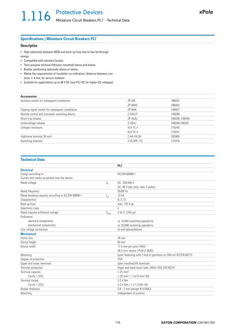
1.116
116 EATON CORPORATION CA019011EN
Protective Devices
Miniature Circuit Breakers PL7 - Technical Data
Specifi cations | Miniature Circuit Breakers PL7
Description
• High selectivity between MCB and back-up fuse due to low let-through energy• Compatible with standard busbar• Twin-purpose terminal (lift/open-mouthed) above and below• Busbar positioning optionally above or below• Meets the requirements of insulation co-ordination, distance between con-
tacts 4 mm, for secure isolation• Suitable for applications up to 48 V DC (use PL7-DC for higher DC voltages)
Accessories:Auxiliary switch for subsequent installation ZP-IHK 286052
ZP-WHK 286053Tripping signal switch for subsequent installation ZP-NHK 248437Remote control and automatic switching device Z-FW/LP 248296Shunt trip release ZP-ASA/.. 248438, 248439Undervoltage release Z-USA/.. 248288-248291Compact enclosure KLV-TC-2 276240
KLV-TC-4 276241Additional terminal 35 mm2 Z-HA-EK/35 263960Switching interlock Z-IS/SPE-1TE 274418
Technical DataPL7
ElectricalDesign according toCurrent test marks as printed onto the device
IEC/EN 60898-1
Rated voltage Un AC: 230/400 VDC: 48 V (per pole, max. 2 poles)
Rated frequency 50/60 HzRated breaking capacity according to IEC/EN 60898-1 Icn 10 kACharacteristic B, C, DBack-up fuse max. 125 A gLSelectivity class 3Rated impulse withstand voltage Uimp 4 kV (1.2/50 μs)Endurance
electrical components 10,000 switching operationsmechanical components 20,000 switching operations
Line voltage connection at will (above/below)MechanicalFrame size 45 mmDevice height 80 mmDevice width 17.5 mm per pole (1MU)
26.3 mm: device 1P+N (1.5MU)Mounting quick fastening with 3 lock-in positions on DIN rail IEC/EN 60715Degree of protection IP20Upper and lower terminals open mouthed/lift terminalsTerminal protection fi nger and hand touch safe, DGUV VS3, EN 50274Terminal capacity 1-25 mm2
(1p+N, 1,5TE) 1-25 mm2 / 1-2x10 mm2 (N)Terminal torque 2-2.4 Nm
(1p+N, 1,5TE) 2-2.4 Nm / 1.2-1.5 Nm (N)Busbar thickness 0.8 - 2 mm (except N 0.5MU)Mounting independent of position

1.117
117 EATON CORPORATION CA019011EN
Protective DevicesMiniature Circuit Breakers PL7 - Technical Data
Connection diagrams1-pole 1+N-pole (1.5MU) 2-pole 3-pole 3+N-pole
Dimensions (mm)2P
Tripping Characteristics (IEC/EN 60898-1)
1+N-pole (1.5MU)
Quick-acting (B), slow (C), very slow (D)
Tripping characteristic B Tripping characteristic C Tripping characteristic D
TRIPPING CURRENT
TRIP
PIN
G T
IME
Sec
onds
Min
utes
TRIPPING CURRENT
TRIP
PIN
G T
IME
Sec
onds
Min
utes
TRIPPING CURRENT
TRIP
PIN
G T
IME
Sec
onds
Min
utes
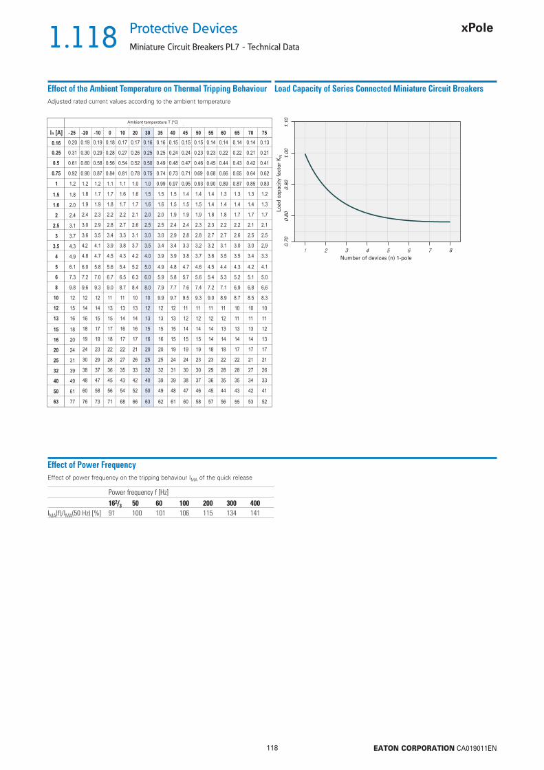
1.118
118 EATON CORPORATION CA019011EN
Protective Devices
Miniature Circuit Breakers PL7 - Technical Data
Effect of the Ambient Temperature on Thermal Tripping Behaviour
Effect of Power FrequencyEffect of power frequency on the tripping behaviour IMA of the quick release
Load Capacity of Series Connected Miniature Circuit Breakers
Power frequency f [Hz]162/3 50 60 100 200 300 400
IMA(f)/IMA(50 Hz) [%] 91 100 101 106 115 134 141
Adjusted rated current values according to the ambient temperature
Ambient temperature T [°C]
Number of devices (n) 1-pole
Load
cap
acity
fac
tor
KN

1.119
119 EATON CORPORATION CA019011EN
Protective DevicesMiniature Circuit Breakers PL7 - Technical Data
Let-through Energy PL7
Let-through Energy PL7, Characteristic B, 1-pole Let-through Energy PL7, Characteristic C, 1-pole
Let-through Energy PL7, Characteristic D, 1-pole
Prospective short-circuit current [A]
Let
thro
ugh
ener
gy I2
t [A
2 se
c]
Prospective short-circuit current [A]
Let
thro
ugh
ener
gy I2
t [A
2 se
c]
Prospective short-circuit current [A]
Let
thro
ugh
ener
gy I2
t [A
2 se
c]

1.120
120 EATON CORPORATION CA019011EN
Protective Devices
Miniature Circuit Breakers PL7 - Technical Data
Short Circuit Selectivity PL7 towards DII-DIV fuse linkIn case of short circuit, there is selectivity between the miniature circuit breakers PL7 and the upstream fuses up to the specifi ed values of the selectivity limit current Is [kA] (i. e. in case of short-circuit currents Iks under Is only the MCB will trip, in case of short circuit currents above this value both protective devices will respond).*) basically in accordance with EN 60898-1 D.5.2.b
Short circuit selectivity Characteristic B towards fuse link DII-DIV*) Short circuit selectivity Characteristic C towards fuse link DII-DIV*)
Short circuit selectivity Characteristic D towards fuse link DII-DIV*)
1) Selectivity limit current Is under 0.5 kA2) Selectivity limit current Is = rated breaking capacity Icn of the MCBDarker areas: no selectivity
PL7 DII-DIV gL/gGIn [A] 10 16 20 25 35 50 63 80 1002 <0.51) <0.51) 0.8 1.6 10.02) 10.02) 10.02) 10.02) 10.02)
4 <0.51) <0.51) 0.6 1.0 3.6 10.02) 10.02) 10.02) 10.02)
5 <0.51) <0.51) 0.6 0.9 2.0 3.5 8.5 10.02) 10.02)
6 <0.51) 0.6 0.9 1.8 3.2 7.4 10.02) 10.02)
8 <0.51) 0.5 0.8 1.6 2.6 5.2 8.3 10.02)
10 0.5 0.8 1.4 2.2 3.9 6.0 10.02)
13 0.5 0.7 1.3 2.0 3.6 5.4 10.02)
16 0.6 1.2 1.9 3.2 4.6 8.420 1.2 1.8 3.1 4.4 7.825 1.2 1.8 3.0 4.2 7.332 1.7 2.8 3.9 6.840 2.7 3.8 6.550 2.5 3.5 5.763 5.3
PL7 DII-DIV gL/gGIn [A] 10 16 20 25 35 50 63 80 1000.75 1.0 10.02) 10.02) 10.02) 10.02) 10.02) 10.02) 10.02) 10.02)
1.0 <0.51) 1.2 10.02) 10.02) 10.02) 10.02) 10.02) 10.02) 10.02)
1.6 <0.51) <0.51) 1.0 2.2 10.02) 10.02) 10.02) 10.02) 10.02)
2 <0.51) <0.51) 0.8 1.6 10.02) 10.02) 10.02) 10.02) 10.02)
4 <0.51) <0.51) 0.6 0.8 1.8 3.6 9.7 10.02) 10.02)
5 <0.51) <0.51) 0.6 0.7 1.5 2.7 7.3 10.02) 10.02)
6 <0.51) 0.5 0.6 1.4 2.4 5.5 10.02) 10.02)
8 <0.51) <0.51) 0.6 1.3 2.2 4.7 8.7 10.02)
10 <0.51) 0.6 1.3 2.0 3.6 5.4 10.02)
13 1.3 1.9 3.3 5.0 9.416 1.2 1.8 3.2 4.4 8.020 1.2 1.8 3.1 4.1 7.025 1.7 2.8 3.8 6.532 2.7 3.7 6.240 3.5 5.950 5.563
PL7 DII-DIV gL/gGIn [A] 10 16 20 25 35 50 63 80 1002 <0.51) <0.51) 0.6 1.0 2.8 5.8 10.02) 10.02) 10.02)
4 <0.51) 0.6 0.9 2.0 3.8 9.5 10.02) 10.02)
5 <0.51) 0.5 0.7 1.7 3.1 7.0 10.02) 10.02)
6 0.5 0.7 1.5 2.6 5.3 9.1 10.02)
8 <0.51) 0.7 1.4 2.2 3.9 6.0 10.02)
10 0.7 1.2 1.9 3.4 5.0 9.513 1.2 1.8 3.2 4.6 8.616 1.6 2.7 4.0 7.420 1.5 2.5 3.5 6.725 2.4 3.4 6.232 2.8 5.040 4.8
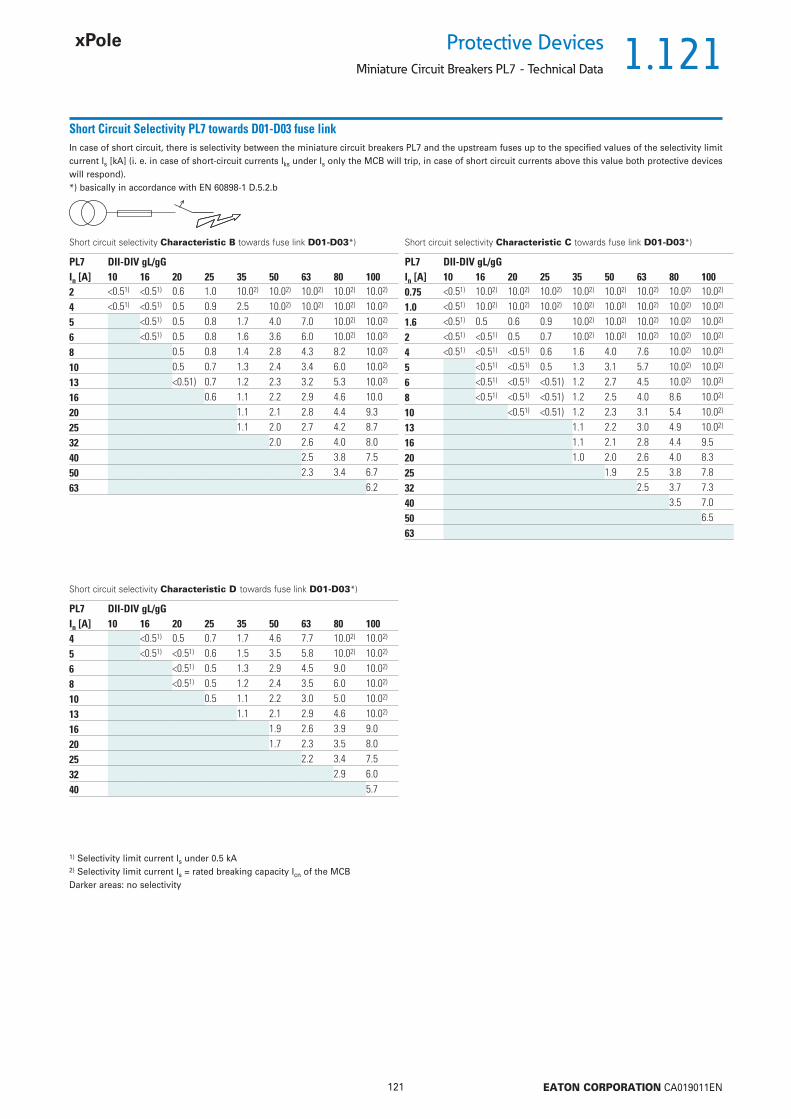
1.121
121 EATON CORPORATION CA019011EN
Protective DevicesMiniature Circuit Breakers PL7 - Technical Data
Short Circuit Selectivity PL7 towards D01-D03 fuse linkIn case of short circuit, there is selectivity between the miniature circuit breakers PL7 and the upstream fuses up to the specifi ed values of the selectivity limit current Is [kA] (i. e. in case of short-circuit currents Iks under Is only the MCB will trip, in case of short circuit currents above this value both protective devices will respond).*) basically in accordance with EN 60898-1 D.5.2.b
Short circuit selectivity Characteristic B towards fuse link D01-D03*) Short circuit selectivity Characteristic C towards fuse link D01-D03*)
Short circuit selectivity Characteristic D towards fuse link D01-D03*)
1) Selectivity limit current Is under 0.5 kA2) Selectivity limit current Is = rated breaking capacity Icn of the MCBDarker areas: no selectivity
PL7 DII-DIV gL/gGIn [A] 10 16 20 25 35 50 63 80 1002 <0.51) <0.51) 0.6 1.0 10.02) 10.02) 10.02) 10.02) 10.02)
4 <0.51) <0.51) 0.5 0.9 2.5 10.02) 10.02) 10.02) 10.02)
5 <0.51) 0.5 0.8 1.7 4.0 7.0 10.02) 10.02)
6 <0.51) 0.5 0.8 1.6 3.6 6.0 10.02) 10.02)
8 0.5 0.8 1.4 2.8 4.3 8.2 10.02)
10 0.5 0.7 1.3 2.4 3.4 6.0 10.02)
13 <0.51) 0.7 1.2 2.3 3.2 5.3 10.02)
16 0.6 1.1 2.2 2.9 4.6 10.020 1.1 2.1 2.8 4.4 9.325 1.1 2.0 2.7 4.2 8.732 2.0 2.6 4.0 8.040 2.5 3.8 7.550 2.3 3.4 6.763 6.2
PL7 DII-DIV gL/gGIn [A] 10 16 20 25 35 50 63 80 1000.75 <0.51) 10.02) 10.02) 10.02) 10.02) 10.02) 10.02) 10.02) 10.02)
1.0 <0.51) 10.02) 10.02) 10.02) 10.02) 10.02) 10.02) 10.02) 10.02)
1.6 <0.51) 0.5 0.6 0.9 10.02) 10.02) 10.02) 10.02) 10.02)
2 <0.51) <0.51) 0.5 0.7 10.02) 10.02) 10.02) 10.02) 10.02)
4 <0.51) <0.51) <0.51) 0.6 1.6 4.0 7.6 10.02) 10.02)
5 <0.51) <0.51) 0.5 1.3 3.1 5.7 10.02) 10.02)
6 <0.51) <0.51) <0.51) 1.2 2.7 4.5 10.02) 10.02)
8 <0.51) <0.51) <0.51) 1.2 2.5 4.0 8.6 10.02)
10 <0.51) <0.51) 1.2 2.3 3.1 5.4 10.02)
13 1.1 2.2 3.0 4.9 10.02)
16 1.1 2.1 2.8 4.4 9.520 1.0 2.0 2.6 4.0 8.325 1.9 2.5 3.8 7.832 2.5 3.7 7.340 3.5 7.050 6.563
PL7 DII-DIV gL/gGIn [A] 10 16 20 25 35 50 63 80 1004 <0.51) 0.5 0.7 1.7 4.6 7.7 10.02) 10.02)
5 <0.51) <0.51) 0.6 1.5 3.5 5.8 10.02) 10.02)
6 <0.51) 0.5 1.3 2.9 4.5 9.0 10.02)
8 <0.51) 0.5 1.2 2.4 3.5 6.0 10.02)
10 0.5 1.1 2.2 3.0 5.0 10.02)
13 1.1 2.1 2.9 4.6 10.02)
16 1.9 2.6 3.9 9.020 1.7 2.3 3.5 8.025 2.2 3.4 7.532 2.9 6.040 5.7

1.122
122 EATON CORPORATION CA019011EN
Protective Devices
Miniature Circuit Breakers PL7 - Technical Data
Short Circuit Selectivity PL7 towards NH-00 fuse linkIn case of short circuit, there is selectivity between the miniature circuit breakers PL7 and the upstream fuses up to the specifi ed values of the selectivity limit current Is [kA] (i. e. in case of short-circuit currents Iks under Is only the MCB will trip, in case of short circuit currents above this value both protective devices will respond).*) basically in accordance with EN 60898-1 D.5.2.b
Short circuit selectivity Characteristic B towards fuse link NH-00*) Short circuit selectivity Characteristic C towards fuse link NH-00*)
Short circuit selectivity Characteristic D towards fuse link NH-00*)
1) Selectivity limit current Is under 0.5 kA2) Selectivity limit current Is = rated breaking capacity Icn of the MCBDarker areas: no selectivity
PL7 NH-00 gL/gGIn [A] 16 20 25 32 35 40 50 63 80 100 125 1602 <0.51) 0.5 1.0 2.5 10.02) 10.02) 10.02) 10.02) 10.02) 10.02) 10.02) 10.02)
4 <0.51) <0.51) 0.8 1.3 2.3 4.3 10.02) 10.02) 10.02) 10.02) 10.02) 10.02)
5 <0.51) <0.51) 0.7 1.1 1.6 2.2 3.6 4.8 8.9 10.02) 10.02) 10.02)
6 <0.51) <0.51) 0.7 1.1 1.5 2.0 3.3 4.3 7.6 10.02) 10.02) 10.02)
8 <0.51) <0.51) 0.6 1.0 1.3 1.7 2.6 3.3 5.2 10.02) 10.02) 10.02)
10 <0.51) 0.6 0.9 1.2 1.5 2.2 2.7 4.0 9.0 10.02) 10.02)
13 <0.51) 0.6 0.8 1.1 1.4 2.1 2.6 3.8 7.9 10.02) 10.02)
16 0.5 0.7 1.0 1.3 1.9 2.4 3.4 6.4 9.3 10.02)
20 0.7 1.0 1.3 1.9 2.4 3.3 6.0 8.7 10.02)
25 0.7 1.0 1.3 1.8 2.3 3.2 5.7 8.0 10.02)
32 0.9 1.2 1.7 2.2 3.1 5.4 7.6 10.02)
40 2.1 3.0 5.1 7.2 10.02)
50 1.9 2.8 4.7 6.6 9.563 4.4 6.3 8.6
PL7 NH-00 gL/gGIn [A] 16 20 25 32 35 40 50 63 80 100 125 1600.75 10.02) 10.02) 10.02) 10.02) 10.02) 10.02) 10.02) 10.02) 10.02) 10.02) 10.02) 10.02)
1.0 0.9 10.02) 10.02) 10.02) 10.02) 10.02) 10.02) 10.02) 10.02) 10.02) 10.02) 10.02)
1.6 <0.51) 0.6 1.3 4.2 10.02) 10.02) 10.02) 10.02) 10.02) 10.02) 10.02) 10.02)
2 <0.51) 0.6 1.0 2.5 10.02) 10.02) 10.02) 10.02) 10.02) 10.02) 10.02) 10.02)
4 <0.51) <0.51) 0.7 1.0 1.5 2.1 3.6 5.0 10.0 10.02) 10.02) 10.02)
5 <0.51) <0.51) 0.6 0.8 1.2 1.7 2.8 3.8 8.7 10.02) 10.02) 10.02)
6 <0.51) <0.51) 0.5 0.8 1.2 1.5 2.5 3.3 5.7 10.02) 10.02) 10.02)
8 <0.51) <0.51) 0.5 0.8 1.1 1.5 2.3 2.9 4.9 10.02) 10.02) 10.02)
10 0.5 0.7 1.0 1.4 2.0 2.5 3.8 8.0 10.02) 10.02)
13 1.0 1.3 1.9 2.4 3.6 7.0 10.02) 10.02)
16 1.0 1.3 1.8 2.3 3.3 6.0 8.8 10.02)
20 1.0 1.2 1.7 2.2 3.2 5.5 7.7 10.02)
25 1.6 2.1 3.0 5.2 7.3 10.02)
32 2.1 2.9 5.0 7.0 10.02)
40 2.8 4.8 6.7 10.050 4.5 6.3 9.563 5.9 8.4
PL7 NH-00 gL/gGIn [A] 16 20 25 32 35 40 50 63 80 100 125 1604 <0.51) <0.51) 0.7 1.0 1.6 2.2 3.8 5.2 10.0 10.02) 10.02) 10.02)
5 <0.51) 0.6 0.9 1.4 1.9 3.2 4.1 7.1 10.02) 10.02) 10.02)
6 <0.51) 0.5 0.8 1.2 1.6 2.6 3.3 5.5 10.02) 10.02) 10.02)
8 0.5 0.8 1.1 1.5 2.2 2.7 4.1 8.7 10.02) 10.02)
10 0.5 0.7 1.0 1.3 1.9 2.5 3.6 7.2 10.02) 10.02)
13 1.0 1.3 1.9 2.3 3.4 6.5 9.5 10.02)
16 1.1 1.6 2.0 3.0 5.5 8.0 10.02)
20 1.4 1.8 2.8 5.0 7.5 10.02)
25 1.8 2.7 4.8 7.0 10.02)
32 2.4 4.1 6.2 9.340 4.0 6.0 9.0
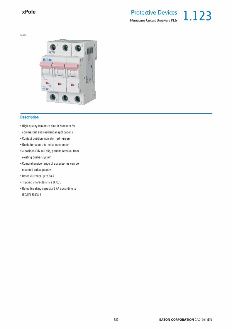
1.123
123 EATON CORPORATION CA019011EN
Protective DevicesMiniature Circuit Breakers PL6
• High-quality miniature circuit breakers for
commercial and residential applications
• Contact position indicator red - green
• Guide for secure terminal connection
• 3-position DIN rail clip, permits removal from
existing busbar system
• Comprehensive range of accessories can be
mounted subsequently
• Rated currents up to 63 A
• Tripping characteristics B, C, D
• Rated breaking capacity 6 kA according to
IEC/EN 60898-1
Description
SG62211

1.124
124 EATON CORPORATION CA019011EN
Protective Devices
Miniature Circuit Breakers PL6
Rated currentIn (A)
TypeDesignation
Article No. Units perpackage
6 kA, Characteristic BSG45411
1 PL6-B1/1 164740 12/1201.5 PL6-B1,5/1 164736 12/1201.6 PL6-B1,6/1 164737 12/1202 PL6-B2/1 286516 12/1202.5 PL6-B2,5/1 164741 12/1203 PL6-B3/1 164743 12/1203.5 PL6-B3,5/1 164742 12/1204 PL6-B4/1 286517 12/1205 PL6-B5/1 164744 12/1206 PL6-B6/1 286518 12/1208 PL6-B8/1 164745 12/12010 PL6-B10/1 286519 12/12012 PL6-B12/1 164738 12/12013 PL6-B13/1 286520 12/12015 PL6-B15/1 164739 12/12016 PL6-B16/1 286521 12/12020 PL6-B20/1 286522 12/12025 PL6-B25/1 286523 12/12032 PL6-B32/1 286524 12/12040 PL6-B40/1 286525 12/12050 PL6-B50/1 286526 12/12063 PL6-B63/1 286527 12/120
1-pole
SG51411
1 PL6-B1/1N 164903 8/801.5 PL6-B1,5/1N 164901 8/801.6 PL6-B1,6/1N 164902 8/802 PL6-B2/1N 164907 8/802.5 PL6-B2,5/1N 164906 8/803 PL6-B3/1N 164911 8/803.5 PL6-B3,5/1N 164910 8/804 PL6-B4/1N 164913 8/805 PL6-B5/1N 164914 8/806 PL6-B6/1N 106025 8/808 PL6-B8/1N 164915 8/8010 PL6-B10/1N 106026 8/8012 PL6-B12/1N 164904 8/8013 PL6-B13/1N 106027 8/8015 PL6-B15/1N 164905 8/8016 PL6-B16/1N 106028 8/8020 PL6-B20/1N 164908 8/8025 PL6-B25/1N 164909 8/8032 PL6-B32/1N 164912 8/80
1+N-pole

1.125
125 EATON CORPORATION CA019011EN
Protective DevicesMiniature Circuit Breakers PL6
Rated currentIn (A)
TypeDesignation
Article No. Units perpackage
SG51511
1 PL6-B1/2 164803 6/601.5 PL6-B1,5/2 164801 6/601.6 PL6-B1,6/2 164802 6/602 PL6-B2/2 286550 6/602.5 PL6-B2,5/2 164806 6/603 PL6-B3/2 164808 6/603.5 PL6-B3,5/2 164807 6/604 PL6-B4/2 286551 6/605 PL6-B5/2 164809 6/606 PL6-B6/2 286552 6/608 PL6-B8/2 164810 6/6010 PL6-B10/2 286553 6/6012 PL6-B12/2 164804 6/6013 PL6-B13/2 286554 6/6015 PL6-B15/2 164805 6/6016 PL6-B16/2 286555 6/6020 PL6-B20/2 286556 6/6025 PL6-B25/2 286557 6/6032 PL6-B32/2 286558 6/6040 PL6-B40/2 286559 6/6050 PL6-B50/2 286560 6/6063 PL6-B63/2 286561 6/60
2-pole
SG62211
1 PL6-B1/3 164868 4/401.5 PL6-B1,5/3 164866 4/401.6 PL6-B1,6/3 164867 4/402 PL6-B2/3 286584 4/402.5 PL6-B2,5/3 164871 4/403 PL6-B3/3 164873 4/403.5 PL6-B3,5/3 164872 4/404 PL6-B4/3 286585 4/405 PL6-B5/3 164874 4/406 PL6-B6/3 286586 4/408 PL6-B8/3 164875 4/4010 PL6-B10/3 286587 4/4012 PL6-B12/3 164869 4/4013 PL6-B13/3 286588 4/4015 PL6-B15/3 164870 4/4016 PL6-B16/3 286589 4/4020 PL6-B20/3 286590 4/4025 PL6-B25/3 286591 4/4032 PL6-B32/3 286592 4/4040 PL6-B40/3 286593 4/4050 PL6-B50/3 286594 4/4063 PL6-B63/3 286595 4/40
3-pole

1.126
126 EATON CORPORATION CA019011EN
Protective Devices
Miniature Circuit Breakers PL6
Rated currentIn (A)
TypeDesignation
Article No. Units perpackage
SG64711
1 PL6-B1/3N 165002 3/301.5 PL6-B1,5/3N 165000 3/301.6 PL6-B1,6/3N 165001 3/302 PL6-B2/3N 165007 3/302.5 PL6-B2,5/3N 165006 3/303 PL6-B3/3N 165009 3/303.5 PL6-B3,5/3N 165008 3/304 PL6-B4/3N 165010 3/305 PL6-B5/3N 165011 3/306 PL6-B6/3N 106035 3/308 PL6-B8/3N 165012 3/3010 PL6-B10/3N 106036 3/3012 PL6-B12/3N 165003 3/3013 PL6-B13/3N 165004 3/3015 PL6-B15/3N 165005 3/3016 PL6-B16/3N 106037 3/3020 PL6-B20/3N 106038 3/3025 PL6-B25/3N 106039 3/3032 PL6-B32/3N 106040 3/3040 PL6-B40/3N 106041 3/3050 PL6-B50/3N 106903 3/3063 PL6-B63/3N 106904 3/30
3+N-pole
SG26612
1 PL6-B1/4 166489 3/301.5 PL6-B1,5/4 166487 3/301.6 PL6-B1,6/4 166488 3/302 PL6-B2/4 166496 3/302.5 PL6-B2,5/4 166495 3/303 PL6-B3/4 166499 3/304 PL6-B4/4 166501 3/305 PL6-B5/4 166503 3/306 PL6-B6/4 166505 3/308 PL6-B8/4 166507 3/3010 PL6-B10/4 166490 3/3012 PL6-B12/4 166491 3/3013 PL6-B13/4 166492 3/3015 PL6-B15/4 166493 3/3016 PL6-B16/4 166494 3/3020 PL6-B20/4 166497 3/3025 PL6-B25/4 166498 3/3032 PL6-B32/4 166500 3/3040 PL6-B40/4 166502 3/3050 PL6-B50/4 166504 3/3063 PL6-B63/4 166506 3/30
4-pole

1.127
127 EATON CORPORATION CA019011EN
Protective DevicesMiniature Circuit Breakers PL6
Rated currentIn (A)
TypeDesignation
Article No. Units perpackage
6 kA, Characteristic CSG45411
0.16 PL6-C0.16/1 164746 12/1200.25 PL6-C0,25/1 164747 12/1200.5 PL6-C0,5/1 164748 12/1200.75 PL6-C0,75/1 164749 12/1201 PL6-C1/1 164754 12/1201.5 PL6-C1,5/1 164750 12/1201.6 PL6-C1,6/1 164751 12/1202 PL6-C2/1 286528 12/1202.5 PL6-C2,5/1 164755 12/1203 PL6-C3/1 164757 12/1203.5 PL6-C3,5/1 164756 12/1204 PL6-C4/1 286529 12/1205 PL6-C5/1 164758 12/1206 PL6-C6/1 286530 12/1208 PL6-C8/1 164759 12/12010 PL6-C10/1 286531 12/12012 PL6-C12/1 164752 12/12013 PL6-C13/1 286532 12/12015 PL6-C15/1 164753 12/12016 PL6-C16/1 286533 12/12020 PL6-C20/1 286534 12/12025 PL6-C25/1 286535 12/12032 PL6-C32/1 286536 12/12040 PL6-C40/1 286537 12/12050 PL6-C50/1 286538 12/12063 PL6-C63/1 286539 12/120
1-pole
SG51411
0.16 PL6-C0.16/1N 164916 8/800.25 PL6-C0,25/1N 164917 8/800.5 PL6-C0,5/1N 164918 8/800.75 PL6-C0,75/1N 164919 8/801 PL6-C1/1N 164922 8/801.5 PL6-C1,5/1N 164920 8/801.6 PL6-C1,6/1N 164921 8/802 PL6-C2/1N 106029 8/802.5 PL6-C2,5/1N 164925 8/803 PL6-C3/1N 164929 8/803.5 PL6-C3,5/1N 164928 8/804 PL6-C4/1N 106030 8/805 PL6-C5/1N 164931 8/806 PL6-C6/1N 106031 8/808 PL6-C8/1N 164932 8/8010 PL6-C10/1N 106032 8/8012 PL6-C12/1N 164923 8/8013 PL6-C13/1N 106033 8/8015 PL6-C15/1N 164924 8/8016 PL6-C16/1N 106034 8/8020 PL6-C20/1N 164926 8/8025 PL6-C25/1N 164927 8/8032 PL6-C32/1N 164930 8/80
1+N-pole
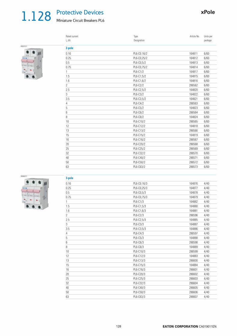
1.128
128 EATON CORPORATION CA019011EN
Protective Devices
Miniature Circuit Breakers PL6
Rated currentIn (A)
TypeDesignation
Article No. Units perpackage
SG51511
0.16 PL6-C0.16/2 164811 6/600.25 PL6-C0,25/2 164812 6/600.5 PL6-C0,5/2 164813 6/600.75 PL6-C0,75/2 164814 6/601 PL6-C1/2 164817 6/601.5 PL6-C1,5/2 164815 6/601.6 PL6-C1,6/2 164816 6/602 PL6-C2/2 286562 6/602.5 PL6-C2,5/2 164820 6/603 PL6-C3/2 164822 6/603.5 PL6-C3,5/2 164821 6/604 PL6-C4/2 286563 6/605 PL6-C5/2 164823 6/606 PL6-C6/2 286564 6/608 PL6-C8/2 164824 6/6010 PL6-C10/2 286565 6/6012 PL6-C12/2 164818 6/6013 PL6-C13/2 286566 6/6015 PL6-C15/2 164819 6/6016 PL6-C16/2 286567 6/6020 PL6-C20/2 286568 6/6025 PL6-C25/2 286569 6/6032 PL6-C32/2 286570 6/6040 PL6-C40/2 286571 6/6050 PL6-C50/2 286572 6/6063 PL6-C63/2 286573 6/60
2-pole
SG62211
0.16 PL6-C0.16/3 164876 4/400.25 PL6-C0,25/3 164877 4/400.5 PL6-C0,5/3 164878 4/400.75 PL6-C0,75/3 164879 4/401 PL6-C1/3 164882 4/401.5 PL6-C1,5/3 164880 4/401.6 PL6-C1,6/3 164881 4/402 PL6-C2/3 286596 4/402.5 PL6-C2,5/3 164885 4/403 PL6-C3/3 164887 4/403.5 PL6-C3,5/3 164886 4/404 PL6-C4/3 286597 4/405 PL6-C5/3 164888 4/406 PL6-C6/3 286598 4/408 PL6-C8/3 164889 4/4010 PL6-C10/3 286599 4/4012 PL6-C12/3 164883 4/4013 PL6-C13/3 286600 4/4015 PL6-C15/3 164884 4/4016 PL6-C16/3 286601 4/4020 PL6-C20/3 286602 4/4025 PL6-C25/3 286603 4/4032 PL6-C32/3 286604 4/4040 PL6-C40/3 286605 4/4050 PL6-C50/3 286606 4/4063 PL6-C63/3 286607 4/40
3-pole
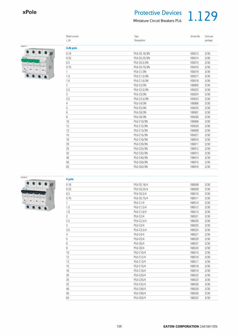
1.129
129 EATON CORPORATION CA019011EN
Protective DevicesMiniature Circuit Breakers PL6
Rated currentIn (A)
TypeDesignation
Article No. Units perpackage
SG64711
0.16 PL6-C0.16/3N 165013 3/300.25 PL6-C0,25/3N 165014 3/300.5 PL6-C0,5/3N 165015 3/300.75 PL6-C0,75/3N 165016 3/301 PL6-C1/3N 165019 3/301.5 PL6-C1,5/3N 165017 3/301.6 PL6-C1,6/3N 165018 3/302 PL6-C2/3N 106905 3/302.5 PL6-C2,5/3N 165022 3/303 PL6-C3/3N 165024 3/303.5 PL6-C3,5/3N 165023 3/304 PL6-C4/3N 106906 3/305 PL6-C5/3N 165025 3/306 PL6-C6/3N 106907 3/308 PL6-C8/3N 165026 3/3010 PL6-C10/3N 106908 3/3012 PL6-C12/3N 165020 3/3013 PL6-C13/3N 106909 3/3015 PL6-C15/3N 165021 3/3016 PL6-C16/3N 106910 3/3020 PL6-C20/3N 106911 3/3025 PL6-C25/3N 106912 3/3032 PL6-C32/3N 106913 3/3040 PL6-C40/3N 106914 3/3050 PL6-C50/3N 106915 3/3063 PL6-C63/3N 106916 3/30
3+N-pole
SG26612
0.16 PL6-C0.16/4 166508 3/300.25 PL6-C0,25/4 166509 3/300.5 PL6-C0,5/4 166510 3/300.75 PL6-C0,75/4 166511 3/301 PL6-C1/4 166514 3/301.5 PL6-C1,5/4 166512 3/301.6 PL6-C1,6/4 166513 3/302 PL6-C2/4 166521 3/302.5 PL6-C2,5/4 166520 3/303 PL6-C3/4 166525 3/303.5 PL6-C3,5/4 166524 3/304 PL6-C4/4 166527 3/305 PL6-C5/4 166529 3/306 PL6-C6/4 166531 3/308 PL6-C8/4 166533 3/3010 PL6-C10/4 166515 3/3012 PL6-C12/4 166516 3/3013 PL6-C13/4 166517 3/3015 PL6-C15/4 166518 3/3016 PL6-C16/4 166519 3/3020 PL6-C20/4 166522 3/3025 PL6-C25/4 166523 3/3032 PL6-C32/4 166526 3/3040 PL6-C40/4 166528 3/3050 PL6-C50/4 166530 3/3063 PL6-C63/4 166532 3/30
4-pole

1.130
130 EATON CORPORATION CA019011EN
Protective Devices
Miniature Circuit Breakers PL6
Rated currentIn (A)
TypeDesignation
Article No. Units perpackage
6 kA, Characteristic DSG45411
0.5 PL6-D0,5/1 164760 12/1201 PL6-D1/1 164765 12/1201.5 PL6-D1,5/1 164761 12/1201.6 PL6-D1,6/1 164762 12/1202 PL6-D2/1 286540 12/1202.5 PL6-D2,5/1 164766 12/1203 PL6-D3/1 164768 12/1203.5 PL6-D3,5/1 164767 12/1204 PL6-D4/1 286541 12/1205 PL6-D5/1 164769 12/1206 PL6-D6/1 286542 12/1208 PL6-D8/1 164770 12/12010 PL6-D10/1 286543 12/12012 PL6-D12/1 164763 12/12013 PL6-D13/1 286544 12/12015 PL6-D15/1 164764 12/12016 PL6-D16/1 286545 12/12020 PL6-D20/1 286546 12/12025 PL6-D25/1 286547 12/12032 PL6-D32/1 286548 12/12040 PL6-D40/1 286549 12/120
1-pole
SG51411
0.5 PL6-D0,5/1N 164933 8/801 PL6-D1/1N 164936 8/801.5 PL6-D1,5/1N 164934 8/801.6 PL6-D1,6/1N 164935 8/802 PL6-D2/1N 164943 8/802.5 PL6-D2,5/1N 164942 8/803 PL6-D3/1N 164947 8/803.5 PL6-D3,5/1N 164946 8/804 PL6-D4/1N 164948 8/805 PL6-D5/1N 164949 8/806 PL6-D6/1N 164950 8/808 PL6-D8/1N 164951 8/8010 PL6-D10/1N 164937 8/8012 PL6-D12/1N 164938 8/8013 PL6-D13/1N 164939 8/8015 PL6-D15/1N 164940 8/8016 PL6-D16/1N 164941 8/8020 PL6-D20/1N 164944 8/8025 PL6-D25/1N 164945 8/80
1+N-pole

1.131
131 EATON CORPORATION CA019011EN
Protective DevicesMiniature Circuit Breakers PL6
Rated currentIn (A)
TypeDesignation
Article No. Units perpackage
SG51511
0.5 PL6-D0,5/2 164825 6/601 PL6-D1/2 164828 6/601.5 PL6-D1,5/2 164826 6/601.6 PL6-D1,6/2 164827 6/602 PL6-D2/2 286574 6/602.5 PL6-D2,5/2 164831 6/603 PL6-D3/2 164833 6/603.5 PL6-D3,5/2 164832 6/604 PL6-D4/2 286575 6/605 PL6-D5/2 164834 6/606 PL6-D6/2 286576 6/608 PL6-D8/2 164835 6/6010 PL6-D10/2 286577 6/6012 PL6-D12/2 164829 6/6013 PL6-D13/2 286578 6/6015 PL6-D15/2 164830 6/6016 PL6-D16/2 286579 6/6020 PL6-D20/2 286580 6/6025 PL6-D25/2 286581 6/6032 PL6-D32/2 286582 6/6040 PL6-D40/2 286583 6/60
2-pole
SG62211
0.5 PL6-D0,5/3 164890 4/401 PL6-D1/3 164893 4/401.5 PL6-D1,5/3 164891 4/401.6 PL6-D1,6/3 164892 4/402 PL6-D2/3 286608 4/402.5 PL6-D2,5/3 164896 4/403 PL6-D3/3 164898 4/403.5 PL6-D3,5/3 164897 4/404 PL6-D4/3 286609 4/405 PL6-D5/3 164899 4/406 PL6-D6/3 286610 4/408 PL6-D8/3 164900 4/4010 PL6-D10/3 286611 4/4012 PL6-D12/3 164894 4/4013 PL6-D13/3 286612 4/4015 PL6-D15/3 164895 4/4016 PL6-D16/3 286613 4/4020 PL6-D20/3 286614 4/4025 PL6-D25/3 286615 4/4032 PL6-D32/3 286616 4/4040 PL6-D40/3 286617 4/40
3-pole
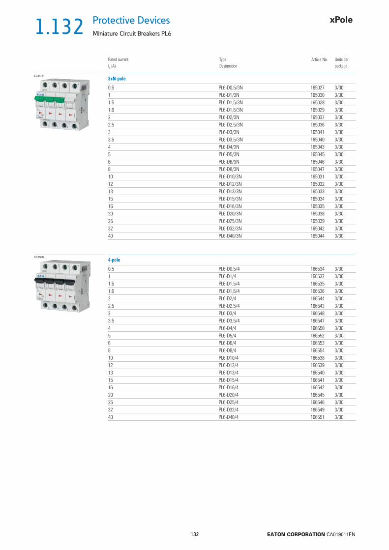
1.132
132 EATON CORPORATION CA019011EN
Protective Devices
Miniature Circuit Breakers PL6
Rated currentIn (A)
TypeDesignation
Article No. Units perpackage
SG64711
0.5 PL6-D0,5/3N 165027 3/301 PL6-D1/3N 165030 3/301.5 PL6-D1,5/3N 165028 3/301.6 PL6-D1,6/3N 165029 3/302 PL6-D2/3N 165037 3/302.5 PL6-D2,5/3N 165036 3/303 PL6-D3/3N 165041 3/303.5 PL6-D3,5/3N 165040 3/304 PL6-D4/3N 165043 3/305 PL6-D5/3N 165045 3/306 PL6-D6/3N 165046 3/308 PL6-D8/3N 165047 3/3010 PL6-D10/3N 165031 3/3012 PL6-D12/3N 165032 3/3013 PL6-D13/3N 165033 3/3015 PL6-D15/3N 165034 3/3016 PL6-D16/3N 165035 3/3020 PL6-D20/3N 165038 3/3025 PL6-D25/3N 165039 3/3032 PL6-D32/3N 165042 3/3040 PL6-D40/3N 165044 3/30
3+N-pole
SG26612
0.5 PL6-D0,5/4 166534 3/301 PL6-D1/4 166537 3/301.5 PL6-D1,5/4 166535 3/301.6 PL6-D1,6/4 166536 3/302 PL6-D2/4 166544 3/302.5 PL6-D2,5/4 166543 3/303 PL6-D3/4 166548 3/303.5 PL6-D3,5/4 166547 3/304 PL6-D4/4 166550 3/305 PL6-D5/4 166552 3/306 PL6-D6/4 166553 3/308 PL6-D8/4 166554 3/3010 PL6-D10/4 166538 3/3012 PL6-D12/4 166539 3/3013 PL6-D13/4 166540 3/3015 PL6-D15/4 166541 3/3016 PL6-D16/4 166542 3/3020 PL6-D20/4 166545 3/3025 PL6-D25/4 166546 3/3032 PL6-D32/4 166549 3/3040 PL6-D40/4 166551 3/30
4-pole

1.133
133 EATON CORPORATION CA019011EN
Protective DevicesMiniature Circuit Breakers PL6 - Technical Data
Specifi cations | Miniature Circuit Breakers PL6
Description
• High selectivity between MCB and back-up fuse due to low let-through energy• Compatible with standard busbar• Twin-purpose terminal (lift/open-mouthed) above and below• Busbar positioning optionally above or below• Meets the requirements of insulation co-ordination, distance between con-
tacts 4 mm, for secure isolation• Suitable for applications up to 48 V DC
Accessories:Auxiliary switch for subsequent installation ZP-IHK 286052
ZP-WHK 286053Tripping signal switch for subsequent installation ZP-NHK 248437Remote control and automatic switching device Z-FW/LP 248296Shunt trip release ZP-ASA/.. 248438, 248439Undervoltage release Z-USA/.. 248288-248291Compact enclosure KLV-TC-2 276240
KLV-TC-4 276241Additional terminal 35 mm2 Z-HA-EK/35 263960Switching interlock Z-IS/SPE-1TE 274418
Technical DataPL6
ElectricalDesign according toCurrent test marks as printed onto the device
IEC/EN 60898-1
Rated voltage Un AC: 230/400 VDC: 48 V (per pole, max. 2 poles)
Rated frequency 50/60 HzRated breaking capacity according to IEC/EN 60898-1 Icn 6 kACharacteristic B, C, DBack-up fuse max. 100 A gLSelectivity class 3Rated impulse withstand voltage Uimp 4 kV (1.2/50 μs)Endurance
electrical components 10,000 switching operationsmechanical components 20,000 switching operations
Line voltage connection at will (above/below)Minimal voltage 12 V AC/DCMechanicalFrame size 45 mmDevice height 80 mmDevice width 17.5 mm per pole (1MU)Mounting quick fastening with 3 lock-in positions on DIN rail IEC/EN 60715Degree of protection IP20Upper and lower terminals open mouthed/lift terminalsTerminal protection fi nger and hand touch safe, DGUV VS3, EN 50274Terminal capacity 1-25 mm2
Terminal torque 2-2.4 NmBusbar thickness 0.8 - 2 mmMounting independent of position

1.134
134 EATON CORPORATION CA019011EN
Protective Devices
Miniature Circuit Breakers PL6 - Technical Data
Connection diagrams
Dimensions (mm)
Tripping Characteristics (IEC/EN 60898-1)
Quick-acting (B), slow (C), very slow (D)
Tripping characteristic B Tripping characteristic C Tripping characteristic D
TRIPPING CURRENT
TRIP
PIN
G T
IME
Sec
onds
Min
utes
TRIPPING CURRENT
TRIP
PIN
G T
IME
Sec
onds
Min
utes
TRIPPING CURRENT
TRIP
PIN
G T
IME
Sec
onds
Min
utes
1-pole 1+N-pole 2-pole 3-pole 3+N-pole 4-pole
17,5 3535 70 70
1P 2P 3P+N 4P1P+N
45808080 80 80
10
30,5
44
60
5,5 4,5
52,5
3P
80

1.135
135 EATON CORPORATION CA019011EN
Protective DevicesMiniature Circuit Breakers PL6 - Technical Data
Effect of the Ambient Temperature on Thermal Tripping Behaviour
Effect of Power FrequencyEffect of power frequency on the tripping behaviour IMA of the quick release
Load Capacity of Series Connected Miniature Circuit Breakers
Power frequency f [Hz]162/3 50 60 100 200 300 400
IMA(f)/IMA(50 Hz) [%] 91 100 101 106 115 134 141
Adjusted rated current values according to the ambient temperature
Ambient temperature T [°C]
Number of devices (n) 1-pole
Load
cap
acity
fac
tor
KN

1.136
136 EATON CORPORATION CA019011EN
Protective Devices
Miniature Circuit Breakers PL6 - Technical Data
Let-through Energy PL6
Let-through Energy PL6, Characteristic B, 1-pole Let-through Energy PL6, Characteristic C, 1-pole
Let-through Energy PL6, Characteristic D, 1-pole
Prospective short-circuit current [A]
Let
thro
ugh
ener
gy I2
t [A
2 se
c]
Prospective short-circuit current [A]
Let
thro
ugh
ener
gy I2
t [A
2 se
c]
Prospective short-circuit current [A]
Let
thro
ugh
ener
gy I2
t [A
2 se
c]

1.137
137 EATON CORPORATION CA019011EN
Protective DevicesMiniature Circuit Breakers PL6 - Technical Data
Short Circuit Selectivity PL6 towards DII-DIV fuse linkIn case of short circuit, there is selectivity between the miniature circuit breakers PL6 and the upstream fuses up to the specifi ed values of the selectivity limit current Is [kA] (i. e. in case of short-circuit currents Iks under Is only the MCB will trip, in case of short circuit currents above this value both protective devices will respond).*) basically in accordance with EN 60898-1 D.5.2.b
Short circuit selectivity Characteristic B towards fuse link DII-DIV*) Short circuit selectivity Characteristic C towards fuse link DII-DIV*)
Short circuit selectivity Characteristic D towards fuse link DII-DIV*)
1) Selectivity limit current Is under 0.5 kA2) Selectivity limit current Is = rated breaking capacity Icn of the MCBDarker areas: no selectivity
PL6 DII-DIV gL/gGIn [A] 10 16 20 25 35 50 63 80 1002 <0.51) <0.51) 0.8 1.6 6.02) 6.02) 6.02) 6.02) 6.02)
4 <0.51) <0.51) 0.6 1.0 3.6 6.02) 6.02) 6.02) 6.02)
5 <0.51) <0.51) 0.6 0.9 2.0 3.5 6.02) 6.02) 6.02)
6 <0.51) 0.6 0.9 1.8 3.2 6.02) 6.02) 6.02)8 <0.51) 0.5 0.8 1.6 2.6 5.2 6.02) 6.02)
10 0.5 0.8 1.4 2.2 3.9 6.02) 6.02)
13 0.5 0.7 1.3 2.0 3.6 5.4 6.02)
16 0.6 1.2 1.9 3.2 4.6 6.02)
20 1.2 1.8 3.1 4.4 6.02)
25 1.2 1.8 3.0 4.2 6.02)
32 1.7 2.8 3.9 6.02)
40 2.7 3.8 6.02)
50 2.5 3.5 5.763 5.3
PL6 DII-DIV gL/gGIn [A] 10 16 20 25 35 50 63 80 1002 <0.51) <0.51) 0.8 1.6 6.02) 6.02) 6.02) 6.02) 6.02)
4 <0.51) <0.51) 0.6 0.8 1.8 3.6 6.02) 6.02) 6.02)
5 <0.51) <0.51) 0.6 0.7 1.5 2.7 6.02) 6.02) 6.02)
6 <0.51) 0.5 0.6 1.4 2.4 5.5 6.02) 6.02)
8 <0.51) <0.51) 0.6 1.3 2.2 4.7 6.02) 6.02)
10 <0.51) 0.6 1.3 2.0 3.6 6.02) 6.02)
13 1.3 1.9 3.3 5.0 6.02)
16 1.2 1.8 3.2 4.4 6.02)
20 1.2 1.8 3.1 4.1 6.02)
25 1.7 2.8 3.8 6.02)
32 2.7 3.7 6.02)
40 3.5 5.950 5.5
PL6 DII-DIV gL/gGIn [A] 10 16 20 25 35 50 63 80 1002 <0.51) <0.51) 0.6 1.0 2.8 5.8 6.02) 6.02) 6.02)
4 <0.51) 0.6 0.9 2.0 3.8 6.02) 6.02) 6.02)
5 <0.51) 0.5 0.7 1.7 3.1 6.02) 6.02) 6.02)
6 0.5 0.7 1.5 2.6 5.3 6.02) 6.02)
8 <0.51) 0.7 1.4 2.2 3.9 6.02) 6.02)
10 0.7 1.2 1.9 3.4 5.0 6.02)
13 1.2 1.8 3.2 4.6 6.02)
16 1.6 2.7 4.0 6.02)
20 1.5 2.5 3.5 6.02)
25 2.4 3.4 6.02)
32 2.8 5.040 4.8
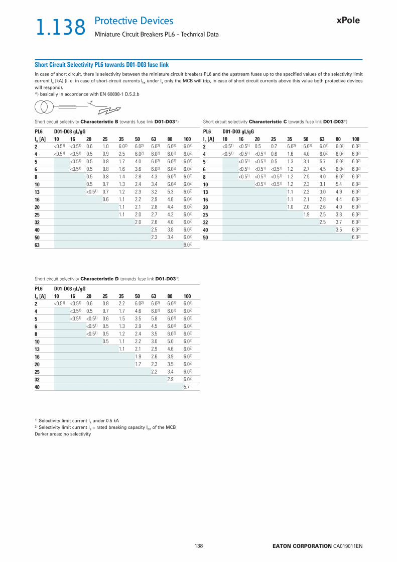
1.138
138 EATON CORPORATION CA019011EN
Protective Devices
Miniature Circuit Breakers PL6 - Technical Data
Short Circuit Selectivity PL6 towards D01-D03 fuse linkIn case of short circuit, there is selectivity between the miniature circuit breakers PL6 and the upstream fuses up to the specifi ed values of the selectivity limit current Is [kA] (i. e. in case of short-circuit currents Iks under Is only the MCB will trip, in case of short circuit currents above this value both protective devices will respond).*) basically in accordance with EN 60898-1 D.5.2.b
Short circuit selectivity Characteristic B towards fuse link D01-D03*) Short circuit selectivity Characteristic C towards fuse link D01-D03*)
Short circuit selectivity Characteristic D towards fuse link D01-D03*)
1) Selectivity limit current Is under 0.5 kA2) Selectivity limit current Is = rated breaking capacity Icn of the MCBDarker areas: no selectivity
PL6 D01-D03 gL/gGIn [A] 10 16 20 25 35 50 63 80 1002 <0.51) <0.51) 0.6 1.0 6.02) 6.02) 6.02) 6.02) 6.02)
4 <0.51) <0.51) 0.5 0.9 2.5 6.02) 6.02) 6.02) 6.02)
5 <0.51) 0.5 0.8 1.7 4.0 6.02) 6.02) 6.02)
6 <0.51) 0.5 0.8 1.6 3.6 6.02) 6.02) 6.02)
8 0.5 0.8 1.4 2.8 4.3 6.02) 6.02)
10 0.5 0.7 1.3 2.4 3.4 6.02) 6.02)
13 <0.51) 0.7 1.2 2.3 3.2 5.3 6.02)
16 0.6 1.1 2.2 2.9 4.6 6.02)
20 1.1 2.1 2.8 4.4 6.02)
25 1.1 2.0 2.7 4.2 6.02)
32 2.0 2.6 4.0 6.02)
40 2.5 3.8 6.02)
50 2.3 3.4 6.02)
63 6.02)
PL6 D01-D03 gL/gGIn [A] 10 16 20 25 35 50 63 80 1002 <0.51) <0.51) 0.5 0.7 6.02) 6.02) 6.02) 6.02) 6.02)
4 <0.51) <0.51) <0.51) 0.6 1.6 4.0 6.02) 6.02) 6.02)
5 <0.51) <0.51) 0.5 1.3 3.1 5.7 6.02) 6.02)
6 <0.51) <0.51) <0.51) 1.2 2.7 4.5 6.02) 6.02)
8 <0.51) <0.51) <0.51) 1.2 2.5 4.0 6.02) 6.02)
10 <0.51) <0.51) 1.2 2.3 3.1 5.4 6.02)
13 1.1 2.2 3.0 4.9 6.02)
16 1.1 2.1 2.8 4.4 6.02)
20 1.0 2.0 2.6 4.0 6.02)
25 1.9 2.5 3.8 6.02)
32 2.5 3.7 6.02)
40 3.5 6.02)
50 6.02)
PL6 D01-D03 gL/gGIn [A] 10 16 20 25 35 50 63 80 1002 <0.51) <0.51) 0.6 0.8 2.2 6.02) 6.02) 6.02) 6.02)
4 <0.51) 0.5 0.7 1.7 4.6 6.02) 6.02) 6.02)
5 <0.51) <0.51) 0.6 1.5 3.5 5.8 6.02) 6.02)
6 <0.51) 0.5 1.3 2.9 4.5 6.02) 6.02)
8 <0.51) 0.5 1.2 2.4 3.5 6.02) 6.02)
10 0.5 1.1 2.2 3.0 5.0 6.02)
13 1.1 2.1 2.9 4.6 6.02)
16 1.9 2.6 3.9 6.02)
20 1.7 2.3 3.5 6.02)
25 2.2 3.4 6.02)
32 2.9 6.02)
40 5.7

1.139
139 EATON CORPORATION CA019011EN
Protective DevicesMiniature Circuit Breakers PL6 - Technical Data
Short Circuit Selectivity PL6 towards NH-00 fuse linkIn case of short circuit, there is selectivity between the miniature circuit breakers PL6 and the upstream fuses up to the specifi ed values of the selectivity limit current Is [kA] (i. e. in case of short-circuit currents Iks under Is only the MCB will trip, in case of short circuit currents above this value both protective devices will respond).*) basically in accordance with EN 60898-1 D.5.2.b
Short circuit selectivity Characteristic B towards fuse link NH-00*) Short circuit selectivity Characteristic C towards fuse link NH-00*)
Short circuit selectivity Characteristic D towards fuse link NH-00*)
1) Selectivity limit current Is under 0.5 kA2) Selectivity limit current Is = rated breaking capacity Icn of the MCBDarker areas: no selectivity
PL6 NH-00 gL/gGIn [A] 16 20 25 32 35 40 50 63 80 100 125 1602 <0.51) 0.5 1.0 2.5 6.02) 6.02) 6.02) 6.02) 6.02) 6.02) 6.02) 6.02)
4 <0.51) <0.51) 0.8 1.3 2.3 4.3 6.02) 6.02) 6.02) 6.02) 6.02) 6.02)
5 <0.51) <0.51) 0.7 1.1 1.6 2.2 3.6 4.8 6.02) 6.02) 6.02) 6.02)
6 <0.51) <0.51) 0.7 1.1 1.5 2.0 3.3 4.3 6.02) 6.02) 6.02) 6.02)
8 <0.51) <0.51) 0.6 1.0 1.3 1.7 2.6 3.3 5.2 6.02) 6.02) 6.02)
10 <0.51) 0.6 0.9 1.2 1.5 2.2 2.7 4.0 6.02) 6.02) 6.02)
13 <0.51) 0.6 0.8 1.1 1.4 2.1 2.6 3.8 6.02) 6.02) 6.02)
16 0.5 0.7 1.0 1.3 1.9 2.4 3.4 6.02) 6.02) 6.02)
20 0.7 1.0 1.3 1.9 2.4 3.3 6.02) 6.02) 6.02)
25 0.7 1.0 1.3 1.8 2.3 3.2 5.7 6.02) 6.02)
32 0.9 1.2 1.7 2.2 3.1 5.4 6.02) 6.02)
40 2.1 3.0 5.1 6.02) 6.02)
50 1.9 2.8 4.7 6.02) 6.02)
63 4.4 6.02) 6.02)
PL6 NH-00 gL/gGIn [A] 16 20 25 32 35 40 50 63 80 100 125 1602 <0.51) 0.6 1.0 2.5 6.02) 6.02) 6.02) 6.02) 6.02) 6.02) 6.02) 6.02)
4 <0.51) <0.51) 0.7 1.0 1.5 2.1 3.6 5.0 6.02) 6.02) 6.02) 6.02)
5 <0.51) <0.51) 0.6 0.8 1.2 1.7 2.8 3.8 6.02) 6.02) 6.02) 6.02)
6 <0.51) <0.51) 0.5 0.8 1.2 1.5 2.5 3.3 5.7 6.02) 6.02) 6.02)
8 <0.51) <0.51) 0.5 0.8 1.1 1.5 2.3 2.9 4.9 6.02) 6.02) 6.02)
10 0.5 0.7 1.0 1.4 2.0 2.5 3.8 6.02) 6.02) 6.02)
13 1.0 1.3 1.9 2.4 3.6 6.02) 6.02) 6.02)
16 1.0 1.3 1.8 2.3 3.3 6.02) 6.02) 6.02)
20 1.0 1.2 1.7 2.2 3.2 5.5 6.02) 6.02)
25 1.6 2.1 3.0 5.2 6.02) 6.02)
32 2.1 2.9 5.0 6.02) 6.02)
40 2.8 4.8 6.02) 6.02)
50 4.5 6.02) 6.02)
63 5.9 6.02)
PL6 NH-00 gL/gGIn [A] 16 20 25 32 35 40 50 63 80 100 125 1602 <0.51) <0.51) 0.8 1.3 2.1 3.1 6.02) 6.02) 6.02) 6.02) 6.02) 6.02)
4 <0.51) <0.51) 0.7 1.0 1.6 2.2 3.8 5.2 6.02) 6.02) 6.02) 6.02)
5 <0.51) 0.6 0.9 1.4 1.9 3.2 4.1 6.02) 6.02) 6.02) 6.02)
6 <0.51) 0.5 0.8 1.2 1.6 2.6 3.3 5.5 6.02) 6.02) 6.02)
8 0.5 0.8 1.1 1.5 2.2 2.7 4.1 6.02) 6.02) 6.02)
10 0.5 0.7 1.0 1.3 1.9 2.5 3.6 6.02) 6.02) 6.02)
13 1.0 1.3 1.9 2.3 3.4 6.02) 6.02) 6.02)
16 1.1 1.6 2.0 3.0 5.5 6.02) 6.02)
20 1.4 1.8 2.8 5.0 6.02) 6.02)
25 1.8 2.7 4.8 6.02) 6.02)
32 2.4 4.1 6.02) 6.02)
40 4.0 6.02) 6.02)

1.140
140 EATON CORPORATION CA019011EN
Protective Devices
Miniature Circuit Breakers HL xPole Home
• High-quality miniature circuit breakers for
commercial and residential applications
• Guide for secure terminal connection
• 3-position DIN rail clip, permits removal from
existing busbar system
• Comprehensive range of accessories suitable
for subsequent installation
• Rated currents up to 63 A
• Tripping characteristics B, C
• Rated breaking capacity 4.5 kA according to
IEC/EN 60898-1
Description
sg03518_r

1.141
141 EATON CORPORATION CA019011EN
Protective DevicesMiniature Circuit Breakers HL xPole Home
Rated currentIn (A)
TypeDesignation
Article No. Units perpackage
4.5 kA, Characteristic Bsg02818_r
6 HL-B6/1 194718 12/12010 HL-B10/1 194719 12/12013 HL-B13/1 194720 12/12016 HL-B16/1 194721 12/12020 HL-B20/1 194722 12/12025 HL-B25/1 194723 12/12032 HL-B32/1 194724 12/12040 HL-B40/1 194725 12/12050 HL-B50/1 194726 12/12063 HL-B63/1 194727 12/120
1-pole
sg03218_r
6 HL-B6/1N 194738 6/6010 HL-B10/1N 194739 6/6013 HL-B13/1N 194740 6/6016 HL-B16/1N 194741 6/6020 HL-B20/1N 194742 6/6025 HL-B25/1N 194743 6/6032 HL-B32/1N 194744 6/6040 HL-B40/1N 194745 6/6050 HL-B50/1N 194746 6/6063 HL-B63/1N 194747 6/60
1+N-pole
sg03018_r
6 HL-B6/2 194758 6/6010 HL-B10/2 194759 6/6013 HL-B13/2 194760 6/6016 HL-B16/2 194761 6/6020 HL-B20/2 194762 6/6025 HL-B25/2 194763 6/6032 HL-B32/2 194764 6/6040 HL-B40/2 194765 6/6050 HL-B50/2 194766 6/6063 HL-B63/2 194767 6/60
2-pole
sg03318_r
6 HL-B6/3 194778 4/4010 HL-B10/3 194779 4/4013 HL-B13/3 194780 4/4016 HL-B16/3 194781 4/4020 HL-B20/3 194782 4/4025 HL-B25/3 194783 4/4032 HL-B32/3 194784 4/4040 HL-B40/3 194785 4/4050 HL-B50/3 194786 4/4063 HL-B63/3 194787 4/40
3-pole

1.142
142 EATON CORPORATION CA019011EN
Protective Devices
Miniature Circuit Breakers HL xPole Home
Rated currentIn (A)
TypeDesignation
Article No. Units perpackage
sg03518_r
6 HL-B6/3N 194798 3/3010 HL-B10/3N 194799 3/3013 HL-B13/3N 194800 3/3016 HL-B16/3N 194801 3/3020 HL-B20/3N 194802 3/3025 HL-B25/3N 194803 3/3032 HL-B32/3N 194804 3/3040 HL-B40/3N 194805 3/3050 HL-B50/3N 194806 3/3063 HL-B63/3N 194807 3/30
3+N-pole
4.5 kA, Characteristic Csg02818_r
6 HL-C6/1 194728 12/12010 HL-C10/1 194729 12/12013 HL-C13/1 194730 12/12016 HL-C16/1 194731 12/12020 HL-C20/1 194732 12/12025 HL-C25/1 194733 12/12032 HL-C32/1 194734 12/12040 HL-C40/1 194735 12/12050 HL-C50/1 194736 12/12063 HL-C63/1 194737 12/120
1-pole
sg03218_r
6 HL-C6/1N 194748 6/6010 HL-C10/1N 194749 6/6013 HL-C13/1N 194750 6/6016 HL-C16/1N 194751 6/6020 HL-C20/1N 194752 6/6025 HL-C25/1N 194753 6/6032 HL-C32/1N 194754 6/6040 HL-C40/1N 194755 6/6050 HL-C50/1N 194756 6/6063 HL-C63/1N 194757 6/60
1+N-pole
sg03018_r
6 HL-C6/2 194768 6/6010 HL-C10/2 194769 6/6013 HL-C13/2 194770 6/6016 HL-C16/2 194771 6/6020 HL-C20/2 194772 6/6025 HL-C25/2 194773 6/6032 HL-C32/2 194774 6/6040 HL-C40/2 194775 6/6050 HL-C50/2 194776 6/6063 HL-C63/2 194777 6/60
2-pole
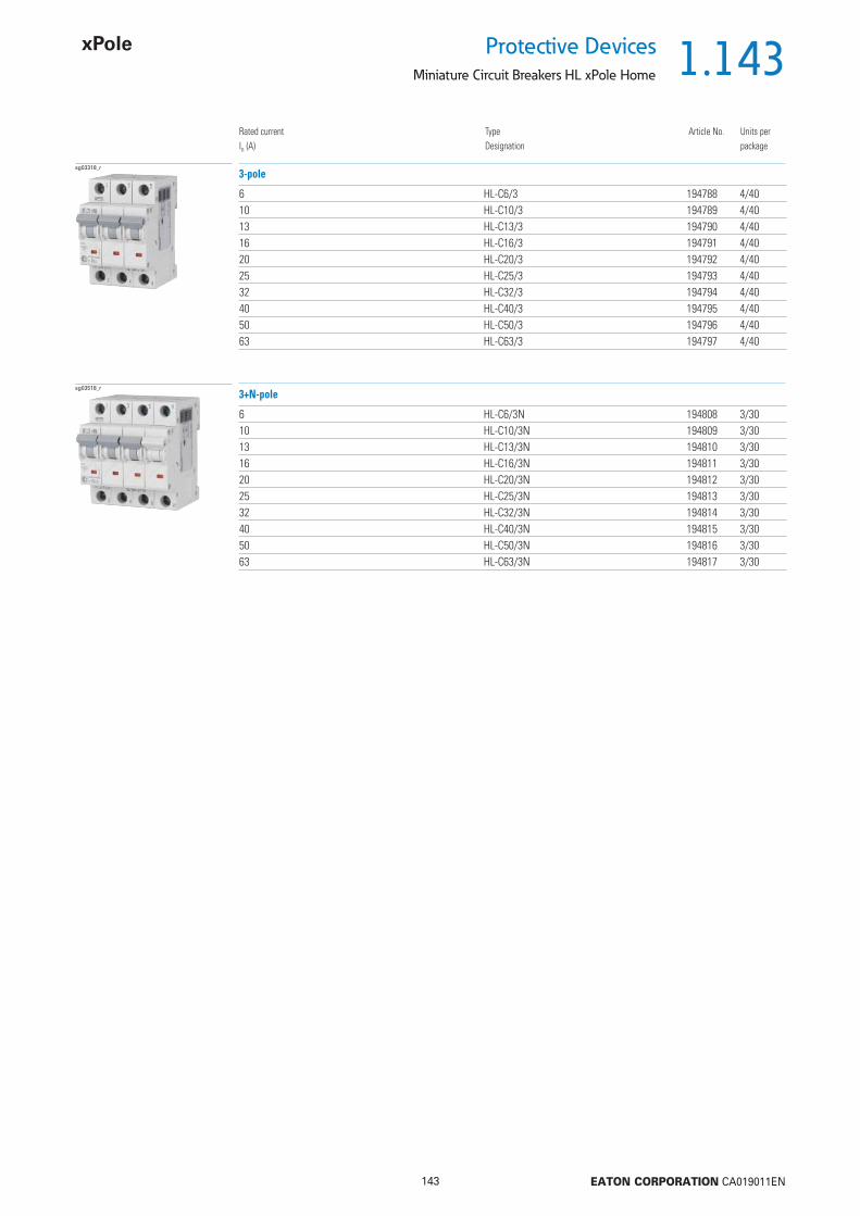
1.143
143 EATON CORPORATION CA019011EN
Protective DevicesMiniature Circuit Breakers HL xPole Home
Rated currentIn (A)
TypeDesignation
Article No. Units perpackage
sg03318_r
6 HL-C6/3 194788 4/4010 HL-C10/3 194789 4/4013 HL-C13/3 194790 4/4016 HL-C16/3 194791 4/4020 HL-C20/3 194792 4/4025 HL-C25/3 194793 4/4032 HL-C32/3 194794 4/4040 HL-C40/3 194795 4/4050 HL-C50/3 194796 4/4063 HL-C63/3 194797 4/40
3-pole
sg03518_r
6 HL-C6/3N 194808 3/3010 HL-C10/3N 194809 3/3013 HL-C13/3N 194810 3/3016 HL-C16/3N 194811 3/3020 HL-C20/3N 194812 3/3025 HL-C25/3N 194813 3/3032 HL-C32/3N 194814 3/3040 HL-C40/3N 194815 3/3050 HL-C50/3N 194816 3/3063 HL-C63/3N 194817 3/30
3+N-pole
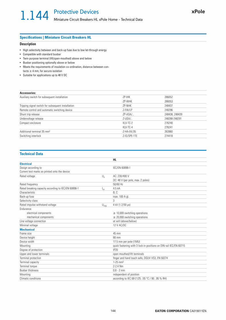
1.144
144 EATON CORPORATION CA019011EN
Protective Devices
Miniature Circuit Breakers HL xPole Home - Technical Data
Specifi cations | Miniature Circuit Breakers HL
Description
• High selectivity between and back-up fuse due to low let-through energy• Compatible with standard busbar• Twin-purpose terminal (lift/open-mouthed) above and below• Busbar positioning optionally above or below• Meets the requirements of insulation co-ordination, distance between con-
tacts 4 mm, for secure isolation• Suitable for applications up to 48 V DC
Accessories:Auxiliary switch for subsequent installation ZP-IHK 286052
ZP-WHK 286053Tripping signal switch for subsequent installation ZP-NHK 248437Remote control and automatic switching device Z-FW/LP 248296Shunt trip release ZP-ASA/.. 248438, 248439Undervoltage release Z-USA/.. 248288-248291Compact enclosure KLV-TC-2 276240
KLV-TC-4 276241Additional terminal 35 mm2 Z-HA-EK/35 263960Switching interlock Z-IS/SPE-1TE 274418
Technical DataHL
ElectricalDesign according toCurrent test marks as printed onto the device
IEC/EN 60898-1
Rated voltage Un AC: 230/400 VDC: 48 V (per pole, max. 2 poles)
Rated frequency 50/60 HzRated breaking capacity according to IEC/EN 60898-1 Icn 4.5 kACharacteristic B, CBack-up fuse max. 100 A gLSelectivity class 3Rated impulse withstand voltage Uimp 4 kV (1.2/50 μs)Endurance
electrical components 10,000 switching operationsmechanical components 20,000 switching operations
Line voltage connection at will (above/below)Minimal voltage 12 V AC/DCMechanicalFrame size 45 mmDevice height 80 mmDevice width 17.5 mm per pole (1MU)Mounting quick fastening with 3 lock-in positions on DIN rail IEC/EN 60715Degree of protection IP20Upper and lower terminals open mouthed/lift terminalsTerminal protection fi nger and hand touch safe, DGUV VS3, EN 50274Terminal capacity 1-25 mm2
Terminal torque 2-2.4 NmBusbar thickness 0.8 - 2 mmMounting independent of positionClimatic conditions according to IEC 68-2 (25...55 °C / 90...95 % RH)
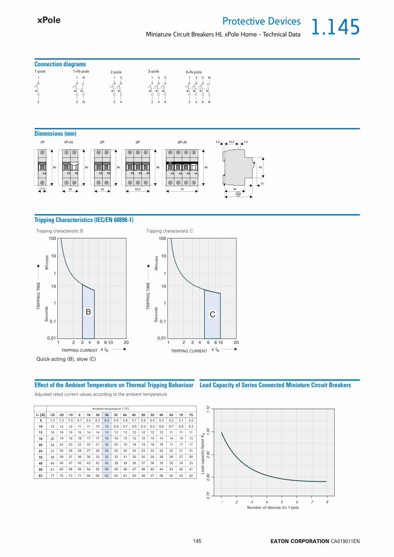
1.145
145 EATON CORPORATION CA019011EN
Protective DevicesMiniature Circuit Breakers HL xPole Home - Technical Data
Connection diagrams1-pole
Dimensions (mm)
17,5 3535 70
1P 2P 3P+N1P+N
808080 80
52,5
3P
80
1+N-pole 2-pole
45
10
30,5
44
60
5,5 4,5
3-pole 3+N-pole
Tripping Characteristics (IEC/EN 60898-1)
Quick-acting (B), slow (C)
Tripping characteristic B Tripping characteristic C
TRIPPING CURRENT
TRIP
PIN
G T
IME
Sec
onds
Min
utes
TRIPPING CURRENT
TRIP
PIN
G T
IME
Sec
onds
Min
utes
Effect of the Ambient Temperature on Thermal Tripping Behaviour Load Capacity of Series Connected Miniature Circuit BreakersAdjusted rated current values according to the ambient temperature
Number of devices (n) 1-pole
Load
cap
acity
fac
tor
KN
Umgebungstemperatur T [°C]
In [A] - 25 -20 -10 0 10 20 30 35 40 45 50 55 60
6 7.3 7.2 7.0 6.7 6.5 6.3 6.0 5.9 5.8 5.7 5.6 5.4 5.3
10 12 12 12 11 11 10 10 9.9 9.7 9.5 9.3 9.0 8.9
13 16 16 15 15 14 14 13 13 13 12 12 12 12
16 20 19 19 18 17 17 16 16 15 15 15 14 14
20 24 24 23 22 22 21 20 20 19 19 19 18 18
25 31 30 29 28 27 26 25 25 24 24 23 23 22
32 39 38 37 36 35 33 32 32 31 30 30 29 28
40 49 48 47 45 43 42 40 39 39 38 37 36 35
50 61 60 58 56 54 52 50 49 48 47 46 45 44
63 77 76 73 71 68 66 63 62 61 60 58 57 56
65
5.2
8.7
11
14
17
22
28
35
43
55
70
5.1
8.5
11
14
17
21
27
34
42
53
75
5.0
8.3
11
13
17
21
26
33
41
52
Ambient temperature T [°C]

1.146
146 EATON CORPORATION CA019011EN
Protective Devices
Miniature Circuit Breakers HL xPole Home - Technical Data
Let-through Energy HL
Let-through Energy HL, Characteristic B, 1-pole Let-through Energy HL, Characteristic C, 1-pole
500
300
50
0
10
00
15
00
20
00
30
00
40
00
50
00
60
00
70
00
10
00
0
15
00
0
80
00
90
00
400
900
700800
600
1500
1000
3000
2000
5000
4000
20000
9000
7000
10000
8000
6000
15000
30000
50000
60000
40000
70000
80000
prospektiver Kurzschlussstrom [A]
Durc
hla
ssenerg
ie I
t [A
sec]
22
B6
B10B13B16B20B25B32B40B50B63
500
300
50
0
10
00
15
00
20
00
30
00
40
00
50
00
60
00
70
00
10
00
0
15
00
0
80
00
90
00
400
900
700800
600
1500
1000
3000
2000
5000
4000
20000
9000
7000
10000
8000
6000
15000
30000
50000
60000
40000
70000
80000
prospektiver Kurzschlussstrom [A]
Durc
hla
ssenerg
ie I
t [A
sec]
22
C6
C10C13C16C20C25C32C40C50C
63
Prospective short-circuit current [A]
Let
thro
ugh
ener
gy I2
t [A
2 se
c]
Prospective short-circuit current [A]
Let
thro
ugh
ener
gy I2
t [A
2 se
c]
Effect of Power FrequencyEffect of power frequency on the tripping behaviour IMA of the quick release
Power frequency f [Hz]162/3 50 60 100 200 300 400
IMA(f)/IMA(50 Hz) [%] 91 100 101 106 115 134 141

1.147
147 EATON CORPORATION CA019011EN
Protective DevicesMiniature Circuit Breakers HL xPole Home - Technical Data
Short Circuit Selectivity HL towards DII-DIV fuse linkIn case of short circuit, there is selectivity between the miniature circuit breakers HL and the upstream fuses up to the specifi ed values of the selectivity limit current Is [kA] (i. e. in case of short-circuit currents Iks under Is only the MCB will trip, in case of short circuit currents above this value both protective devices will respond).*) basically in accordance with EN 60898-1 D.5.2.b
Short circuit selectivity Characteristic B towards fuse link DII-DIV*) Short circuit selectivity Characteristic C towards fuse link DII-DIV*)
HL DII-DIV gL/gGIn [A] 10 16 20 25 35 50 63 80 1006 <0.51) 0.6 0.9 1.8 3.2 4.52) 4.52) 4.52)
10 0.5 0.8 1.4 2.2 3.9 4.52) 4.52)
13 0.5 0.7 1.3 2.0 3.6 4.52) 4.52)
16 0.6 1.2 1.9 3.2 4.52) 4.52)
20 1.2 1.8 3.1 4.4 4.52)
25 1.2 1.8 3.0 4.2 4.52)
32 1.7 2.8 3.9 4.52)
40 2.7 3.8 4.52)
50 2.5 3.5 4.52)
63 4.52)
HL DII-DIV gL/gGIn [A] 10 16 20 25 35 50 63 80 1006 <0.51) 0.5 0.6 1.4 2.4 4.52) 4.52) 4.52)
10 <0.51) 0.6 1.3 2.0 3.6 4.52) 4.52)
13 1.3 1.9 3.3 4.52) 4.52)
16 1.2 1.8 3.2 4.4 4.52)
20 1.2 1.8 3.1 4.1 4.52)
25 1.7 2.8 3.8 4.52)
32 2.7 3.7 4.52)
40 3.5 4.52)
50 4.52)
63
Towards D01-D03 fuse linkShort circuit selectivity Characteristic B towards fuse link D01-D03*) Short circuit selectivity Characteristic C towards fuse link D01-D03*)
HL D01-D03 gL/gGIn [A] 10 16 20 25 35 50 63 80 1006 <0.51) 0.5 0.8 1.6 3.6 4.52) 4.52) 4.52)
10 0.5 0.7 1.3 2.4 3.4 4.52) 4.52)
13 <0.51) 0.7 1.2 2.3 3.2 4.52) 4.52)
16 0.6 1.1 2.2 2.9 4.52) 4.52)
20 1.1 2.1 2.8 4.4 4.52)
25 1.1 2.0 2.7 4.2 4.52)
32 2.0 2.6 4.0 4.52)
40 2.5 3.8 4.52)
50 2.3 3.4 4.52)
63 4.52)
HL D01-D03 gL/gGIn [A] 10 16 20 25 35 50 63 80 1006 <0.51) <0.51) <0.51) 1.2 2.7 4.52) 4.52) 4.52)
10 <0.51) <0.51) 1.2 2.3 3.1 4.52) 4.52)
13 1.1 2.2 3.0 4.52) 4.52)
16 1.1 2.1 2.8 4.4 4.52)
20 1.0 2.0 2.6 4.0 4.52)
25 1.9 2.5 3.8 4.52)
32 2.5 3.7 4.52)
40 3.5 4.52)
50 4.52)
63
Short circuit selectivity Characteristic B towards fuse link NH-00*) Short circuit selectivity Characteristic C towards fuse link NH-00*)
HL NH-00 gL/gGIn [A] 16 20 25 32 35 40 50 63 80 100 125 1606 <0.51) <0.51) 0.7 1.1 1.5 2.0 3.3 4.3 4.52) 4.52) 4.52) 4.52)
10 <0.51) 0.6 0.9 1.2 1.5 2.2 2.7 4.0 4.52) 4.52) 4.52)
13 <0.51) 0.6 0.8 1.1 1.4 2.1 2.6 3.8 4.52) 4.52) 4.52)
16 0.5 0.7 1.0 1.3 1.9 2.4 3.4 4.52) 4.52) 4.52)
20 0.7 1.0 1.3 1.9 2.4 3.3 4.52) 4.52) 4.52)
25 0.7 1.0 1.3 1.8 2.3 3.2 4.52) 4.52) 4.52)
32 0.9 1.2 1.7 2.2 3.1 4.52) 4.52) 4.52)
40 2.1 3.0 4.52) 4.52) 4.52)
50 1.9 2.8 4.52) 4.52) 4.52)
63 4.4 4.52) 4.52)
HL NH-00 gL/gGIn [A] 16 20 25 32 35 40 50 63 80 100 125 1606 <0.51) <0.51) 0.5 0.8 1.2 1.5 2.5 3.3 4.52) 4.52) 4.52) 4.52)
10 0.5 0.7 1.0 1.4 2.0 2.5 3.8 4.52) 4.52) 4.52)
13 1.0 1.3 1.9 2.4 3.6 4.52) 4.52) 4.52)
16 1.0 1.3 1.8 2.3 3.3 4.52) 4.52) 4.52)
20 1.0 1.2 1.7 2.2 3.2 4.52) 4.52) 4.52)
25 1.6 2.1 3.0 4.52) 4.52) 4.52)
32 2.1 2.9 4.52) 4.52) 4.52)
40 2.8 4.52) 4.52) 4.52)
50 4.52) 4.52) 4.52)
63 4.52) 4.52)
1) Selectivity limit current Is under 0.5 kA2) Selectivity limit current Is = rated breaking capacity Icn of the MCBDarker areas: no selectivity
Towards DII-DIV fuse link
Towards NH-00 fuse link
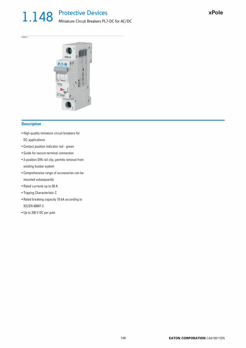
1.148
148 EATON CORPORATION CA019011EN
Protective Devices
Miniature Circuit Breakers PL7-DC for AC/DC
• High-quality miniature circuit breakers for
DC-applications
• Contact position indicator red - green
• Guide for secure terminal connection
• 3-position DIN rail clip, permits removal from
existing busbar system
• Comprehensive range of accessories can be
mounted subsequently
• Rated currents up to 50 A
• Tripping Characteristic C
• Rated breaking capacity 10 kA according to
IEC/EN 60947-2
• Up to 250 V DC per pole
Description
SG06211

1.149
149 EATON CORPORATION CA019011EN
Protective DevicesMiniature Circuit Breakers PL7-DC for AC/DC
Rated currentIn (A)
TypeDesignation
Article No. Units perpackage
10 kA, Characteristic CSG06211
1 PL7-C1/1-DC 264851 12/1202 PL7-C2/1-DC 264883 12/1203 PL7-C3/1-DC 264884 12/1204 PL7-C4/1-DC 264885 12/1206 PL7-C6/1-DC 264886 12/12010 PL7-C10/1-DC 264887 12/12013 PL7-C13/1-DC 264888 12/12016 PL7-C16/1-DC 264889 12/12020 PL7-C20/1-DC 264890 12/12025 PL7-C25/1-DC 264891 12/12032 PL7-C32/1-DC 264892 12/12040 PL7-C40/1-DC 264893 12/12050 PL7-C50/1-DC 264894 12/120
1-pole
SG06411
1 PL7-C1/2-DC 264895 6/602 PL7-C2/2-DC 264896 6/603 PL7-C3/2-DC 264897 6/604 PL7-C4/2-DC 264898 6/606 PL7-C6/2-DC 264899 6/6010 PL7-C10/2-DC 264900 6/6013 PL7-C13/2-DC 264901 6/6016 PL7-C16/2-DC 264902 6/6020 PL7-C20/2-DC 264903 6/6025 PL7-C25/2-DC 264904 6/6032 PL7-C32/2-DC 264905 6/6040 PL7-C40/2-DC 264906 6/6050 PL7-C50/2-DC 264907 6/60
2-pole

1.150
150 EATON CORPORATION CA019011EN
Protective Devices
Miniature Circuit Breakers PL7-DC for AC/DC - Technical Data
Specifi cations | Miniature Circuit Breakers PL7-DC
Description
• High selectivity between MCB and back-up fuse due to low let-through energy• Compatible with standard busbar• Twin-purpose terminal (lift/open-mouthed) above and below• Busbar positioning optionally above or below• Meets the requirements of insulation co-ordination, distance between con-
tacts 4 mm, for secure isolation• Rated breaking capacity 10 kA according to IEC/EN 60947• Rated voltage to 250 V (per pole), = 4 ms• Take into account polarity!
Accessories:Auxiliary switch for subsequent installation ZP-IHK 286052
ZP-WHK 286053Tripping signal switch for subsequent installation ZP-NHK 248437Remote control and automatic switching device Z-FW/LP 248296Shunt trip release ZP-ASA/.. 248438, 248439Undervoltage release Z-USA/.. 248288-248291Compact enclosure KLV-TC-2 276240
KLV-TC-4 276241Additional terminal 35 mm2 Z-HA-EK/35 263960Switching interlock Z-IS/SPE-1TE 274418
Technical DataPL7-DC
ElectricalDesign according toCurrent test marks as printed onto the device
IEC/EN 60947-2
Rated voltage DC 1-2 A types: 220 V (per pole)3-50 A types: 250 V (per pole)
Rated frequency 50/60 HzRated breaking capacity according to IEC/EN 60947-2 10 kACharacteristic CBack-up fuse max. 100 A gLSelectivity class 3Rated impulse withstand voltage Uimp 4 kV (1.2/50 μs)Endurance
electrical components 4,000 switching operationsmechanical components 20,000 switching operations
Line voltage connection at will (above/below)MechanicalFrame size 45 mmDevice height 80 mmDevice width 17.5 mm per pole (1MU)Mounting quick fastening with 3 lock-in positions on DIN rail IEC/EN 60715Degree of protection IP20Upper and lower terminals open mouthed/lift terminalsTerminal protection fi nger and hand touch safe, DGUV VS3, EN 50274Terminal capacity 1-25 mm2
Terminal torque 2-2.4 NmBusbar thickness 0.8 - 2 mmMounting independent of position
Note: not for PV string protection!

1.151
151 EATON CORPORATION CA019011EN
Protective DevicesMiniature Circuit Breakers PL7-DC for AC/DC
Connection diagrams1-pole 2-pole
Dimensions (mm)1P 2P
Connection examples
Connection example at 250 V=, 1-pole Connection example at 500 V=, 2-pole
Tripping characteristic PL7-DC
Type C
Tripping characteristic according to IEC/EN 60898-1
Konventioneller Nicht-Auslösestrom
Conventional tripping current
Let-through Energy PL7-DC
Type C, 250 V d.c., = 5 ms (according to IEC/EN 60947-2)

1.152
152 EATON CORPORATION CA019011EN
Protective Devices
Miniature Circuit Breakers with Plug-in Terminals at the output side PLI
• Contact position indicator red - green
• Two plug-in terminals at the output side
• Single-wire lines can be connected without
tools
• Plug-in terminals can be opened conveniently
by means of a screwdriver
• Guide for secure terminal connection below
• 3-position DIN rail clip, permits removal from
existing busbar system
• Comprehensive range of accessories can be
mounted subsequently
• Rated currents up to 16 A
• Tripping characteristics B, C, D
• Rated breaking capacity 10 kA according to
IEC/EN 60898-1
Description
SG33911

1.153
153 EATON CORPORATION CA019011EN
Protective DevicesMiniature Circuit Breakers with Plug-in Terminals at the output side PLI
Rated currentIn (A)
TypeDesignation
Article No. Units perpackage
10 kA, Characteristic BSG11511
2 PLI-B2/1 101245 12/1204 PLI-B4/1 101246 12/1206 PLI-B6/1 101247 12/1208 PLI-B8/1 101248 12/12010 PLI-B10/1 101249 12/12013 PLI-B13/1 101250 12/12016 PLI-B16/1 101251 12/120
1-pole
Explanation PLI: P = xPole, L = Miniature Circuit Breaker, I = 10 kA, Plug-in Terminals
SG20011
2 PLI-B2/1N 101266 1/604 PLI-B4/1N 101267 1/606 PLI-B6/1N 101268 1/608 PLI-B8/1N 101269 1/6010 PLI-B10/1N 101270 1/6013 PLI-B13/1N 101271 1/6016 PLI-B16/1N 101272 1/60
1+N-pole 2MU
SG19511
2 PLI-B2/2 101287 1/604 PLI-B4/2 101288 1/606 PLI-B6/2 101289 1/608 PLI-B8/2 101290 1/6010 PLI-B10/2 101291 1/6013 PLI-B13/2 101292 1/6016 PLI-B16/2 101293 1/60
2-pole
SG33911
2 PLI-B2/3 101308 1/404 PLI-B4/3 101309 1/406 PLI-B6/3 101310 1/408 PLI-B8/3 101311 1/4010 PLI-B10/3 101312 1/4013 PLI-B13/3 101313 1/4016 PLI-B16/3 101314 1/40
3-pole
SG19211
2 PLI-B2/3N 101329 1/304 PLI-B4/3N 101330 1/306 PLI-B6/3N 101331 1/308 PLI-B8/3N 101332 1/3010 PLI-B10/3N 101333 1/3013 PLI-B13/3N 101334 1/3016 PLI-B16/3N 101335 1/30
3+N-pole
SG39011
2 PLI-B2/4 101350 1/304 PLI-B4/4 101351 1/306 PLI-B6/4 101352 1/308 PLI-B8/4 101353 1/3010 PLI-B10/4 101354 1/3013 PLI-B13/4 101355 1/3016 PLI-B16/4 101356 1/30
4-pole
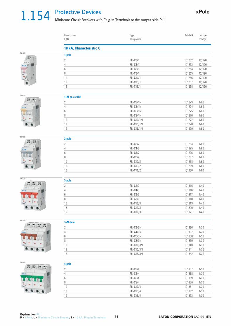
1.154
154 EATON CORPORATION CA019011EN
Protective Devices
Miniature Circuit Breakers with Plug-in Terminals at the output side PLI
Explanation PLI: P = xPole, L = Miniature Circuit Breaker, I = 10 kA, Plug-in Terminals
Rated currentIn (A)
TypeDesignation
Article No. Units perpackage
10 kA, Characteristic CSG11511
2 PLI-C2/1 101252 12/1204 PLI-C4/1 101253 12/1206 PLI-C6/1 101254 12/1208 PLI-C8/1 101255 12/12010 PLI-C10/1 101256 12/12013 PLI-C13/1 101257 12/12016 PLI-C16/1 101258 12/120
1-pole
SG20011
2 PLI-C2/1N 101273 1/604 PLI-C4/1N 101274 1/606 PLI-C6/1N 101275 1/608 PLI-C8/1N 101276 1/6010 PLI-C10/1N 101277 1/6013 PLI-C13/1N 101278 1/6016 PLI-C16/1N 101279 1/60
1+N-pole 2MU
SG19511
2 PLI-C2/2 101294 1/604 PLI-C4/2 101295 1/606 PLI-C6/2 101296 1/608 PLI-C8/2 101297 1/6010 PLI-C10/2 101298 1/6013 PLI-C13/2 101299 1/6016 PLI-C16/2 101300 1/60
2-pole
SG33911
2 PLI-C2/3 101315 1/404 PLI-C4/3 101316 1/406 PLI-C6/3 101317 1/408 PLI-C8/3 101318 1/4010 PLI-C10/3 101319 1/4013 PLI-C13/3 101320 1/4016 PLI-C16/3 101321 1/40
3-pole
SG19211
2 PLI-C2/3N 101336 1/304 PLI-C4/3N 101337 1/306 PLI-C6/3N 101338 1/308 PLI-C8/3N 101339 1/3010 PLI-C10/3N 101340 1/3013 PLI-C13/3N 101341 1/3016 PLI-C16/3N 101342 1/30
3+N-pole
SG39011
2 PLI-C2/4 101357 1/304 PLI-C4/4 101358 1/306 PLI-C6/4 101359 1/308 PLI-C8/4 101360 1/3010 PLI-C10/4 101361 1/3013 PLI-C13/4 101362 1/3016 PLI-C16/4 101363 1/30
4-pole
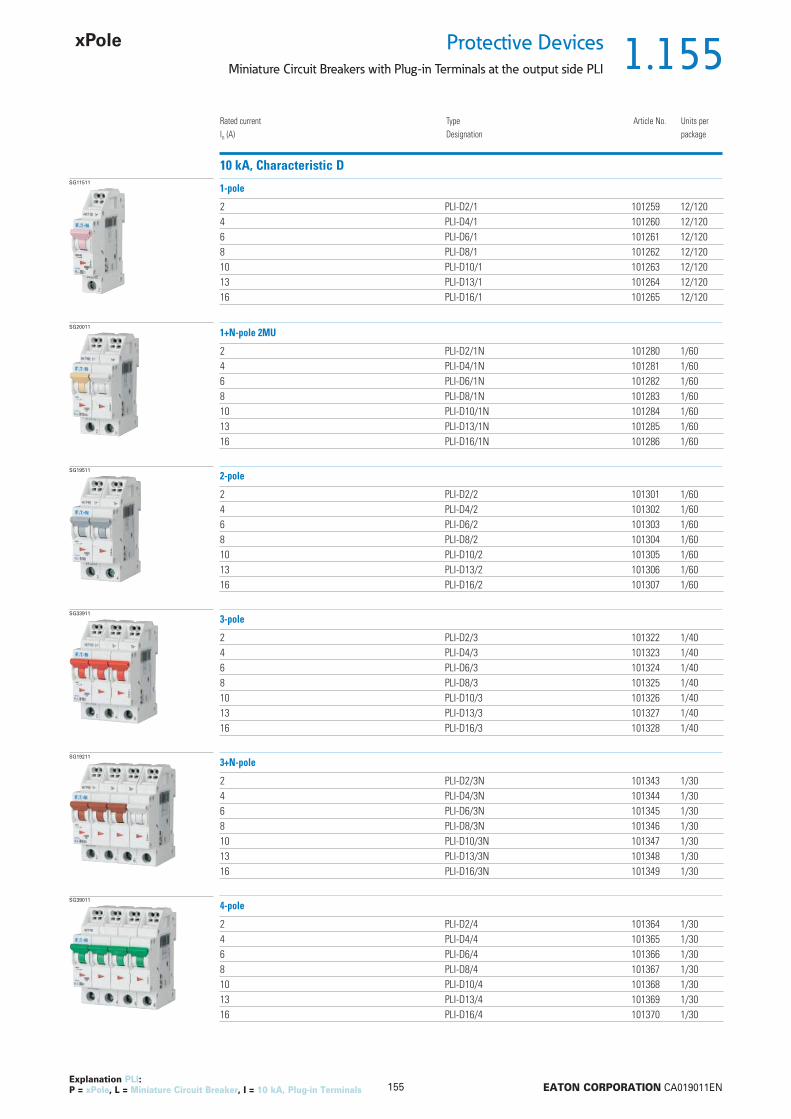
1.155
155 EATON CORPORATION CA019011EN
Protective DevicesMiniature Circuit Breakers with Plug-in Terminals at the output side PLI
Explanation PLI: P = xPole, L = Miniature Circuit Breaker, I = 10 kA, Plug-in Terminals
Rated currentIn (A)
TypeDesignation
Article No. Units perpackage
10 kA, Characteristic DSG11511
2 PLI-D2/1 101259 12/1204 PLI-D4/1 101260 12/1206 PLI-D6/1 101261 12/1208 PLI-D8/1 101262 12/12010 PLI-D10/1 101263 12/12013 PLI-D13/1 101264 12/12016 PLI-D16/1 101265 12/120
1-pole
SG20011
2 PLI-D2/1N 101280 1/604 PLI-D4/1N 101281 1/606 PLI-D6/1N 101282 1/608 PLI-D8/1N 101283 1/6010 PLI-D10/1N 101284 1/6013 PLI-D13/1N 101285 1/6016 PLI-D16/1N 101286 1/60
1+N-pole 2MU
SG19511
2 PLI-D2/2 101301 1/604 PLI-D4/2 101302 1/606 PLI-D6/2 101303 1/608 PLI-D8/2 101304 1/6010 PLI-D10/2 101305 1/6013 PLI-D13/2 101306 1/6016 PLI-D16/2 101307 1/60
2-pole
SG33911
2 PLI-D2/3 101322 1/404 PLI-D4/3 101323 1/406 PLI-D6/3 101324 1/408 PLI-D8/3 101325 1/4010 PLI-D10/3 101326 1/4013 PLI-D13/3 101327 1/4016 PLI-D16/3 101328 1/40
3-pole
SG19211
2 PLI-D2/3N 101343 1/304 PLI-D4/3N 101344 1/306 PLI-D6/3N 101345 1/308 PLI-D8/3N 101346 1/3010 PLI-D10/3N 101347 1/3013 PLI-D13/3N 101348 1/3016 PLI-D16/3N 101349 1/30
3+N-pole
SG39011
2 PLI-D2/4 101364 1/304 PLI-D4/4 101365 1/306 PLI-D6/4 101366 1/308 PLI-D8/4 101367 1/3010 PLI-D10/4 101368 1/3013 PLI-D13/4 101369 1/3016 PLI-D16/4 101370 1/30
4-pole

1.156
156 EATON CORPORATION CA019011EN
Protective Devices
Miniature Circuit Breakers with Plug-in Terminals at the output side PLI - Technical Data
Specifi cations | Miniature Circuit Breakers with Plug-in Terminals at the output side PLI
Description
• High selectivity between MCB and back-up fuse due to low let-through energy• Plug-in terminals above (at the output side)• Two terminal points per pole• Single-wire lines can be connected without tools• The conductor can be removed from the plug-in terminal and single- or fi ne-
wire lines can be connected by means of a screwdriver DIN 5264 Type A and Type B (maximum blade width 3 mm)
• Twin-purpose terminal (lift/open-mouthed) below• Compatible with standard busbar below• Meets the requirements of insulation co-ordination, distance between con-
tacts 4 mm, for secure isolation• Suitable for applications up to 48 V DC
Accessories:Auxiliary switch for subsequent installation ZP-IHK 286052
ZP-WHK 286053Tripping signal switch for subsequent installation ZP-NHK 248437Remote control and automatic switching device Z-FW/LP 248296Shunt trip release ZP-ASA/.. 248438, 248439Undervoltage release Z-USA/.. 248288-248291Compact enclosure KLV-TC-2 276240
KLV-TC-4 276241Additional terminal 35 mm2 Z-HA-EK/35 263960Switching interlock Z-IS/SPE-1TE 274418
Technical DataPLI
ElectricalDesign according toCurrent test marks as printed onto the device
IEC/EN 60898-1
Rated voltage Un AC: 230/400 VDC: 48 V (per pole)
Rated frequency 50/60 HzRated breaking capacity according to IEC/EN 60898-1 Icn 10 kACharacteristic B, C, DBack-up fuse max. 125 A gLSelectivity class 3Rated impulse withstand voltage Uimp 4 kV (1.2/50 μs)Endurance electrical components 8,000 switching operationsLine voltage connection belowMechanicalFrame size 45 mmDevice height 80 mmDevice width 17.5 mm per pole (1MU)Mounting quick fastening with 3 lock-in positions on DIN rail IEC/EN 60715Degree of protection IP20Upper terminals twin plug-in terminalsLower terminals open mouthed/lift terminalsTerminal protection fi nger and hand touch safe, DGUV VS3, EN 50274Upper terminal capacity 1-4 mm2, with wire end sleeve 1-2.5 mm2
Lower terminal capacity 1-25 mm2
Terminal torque 2-2.4 NmBusbar thickness 0.8 - 2 mmMounting independent of position

1.157
157 EATON CORPORATION CA019011EN
Protective DevicesMiniature Circuit Breakers with Plug-in Terminals at the output side PLI - Technical Data
Connection diagrams1-pole 1+N-pole (2MU) 2-pole 3-pole 3+N-pole 4-pole
Dimensions (mm)
17,5 35 70 70
1P 1P+N
2P
3P+N 4P
458484 84 84
10
44
60
52,5
3P
84

1.158
158 EATON CORPORATION CA019011EN
Protective Devices
Miniature Circuit Breakers PLHT
• High-quality miniature circuit breakers for
commercial and industrial applications
• Contact position indicator red - green
• Accessories suitable for subsequent instal-
lation
• Rated currents up to 125 A
• Tripping characteristics B, C, D
• Rated breaking capacity up to 25 kA accord-
ing to EN 60947-2
Description
SG43611

1.159
159 EATON CORPORATION CA019011EN
Protective DevicesMiniature Circuit Breakers PLHT
Rated currentIn (A)
TypeDesignation
Article No. Units perpackage
25 kA, Characteristic BSG41311
20 PLHT-B20 247972 1225 PLHT-B25 247973 1232 PLHT-B32 247974 1240 PLHT-B40 247975 1250 PLHT-B50 247976 1263 PLHT-B63 247977 1280 PLHT-B80 247978 12100 PLHT-B100 247979 12125 PLHT-B125 247980 12
1-pole
SG42111
20 PLHT-B20/2 247998 625 PLHT-B25/2 247999 632 PLHT-B32/2 248000 640 PLHT-B40/2 248001 650 PLHT-B50/2 248002 663 PLHT-B63/2 248003 680 PLHT-B80/2 248004 6100 PLHT-B100/2 248005 6125 PLHT-B125/2 248006 6
2-pole
SG42911
20 PLHT-B20/3 248024 425 PLHT-B25/3 248025 432 PLHT-B32/3 248026 440 PLHT-B40/3 248027 450 PLHT-B50/3 248028 463 PLHT-B63/3 248029 480 PLHT-B80/3 248030 4100 PLHT-B100/3 248031 4125 PLHT-B125/3 248032 4
3-pole
SG45111
20 PLHT-B20/3N 248050 325 PLHT-B25/3N 248051 332 PLHT-B32/3N 248052 340 PLHT-B40/3N 248053 350 PLHT-B50/3N 248054 363 PLHT-B63/3N 248055 380 PLHT-B80/3N 248056 3100 PLHT-B100/3N 248057 3125 PLHT-B125/3N 248058 3
3+N-pole
SG44811
20 PLHT-B20/4 248076 325 PLHT-B25/4 248077 332 PLHT-B32/4 248078 340 PLHT-B40/4 248079 350 PLHT-B50/4 248080 363 PLHT-B63/4 248081 380 PLHT-B80/4 248082 3100 PLHT-B100/4 248083 3125 PLHT-B125/4 248084 3
4-pole
Explanation PLHT: P = xPole, LH = Miniature Circuit Breakers hochwertig, T = Rated breaking capacity 15, 20, 25 kA

1.160
160 EATON CORPORATION CA019011EN
Protective Devices
Miniature Circuit Breakers PLHT
Rated currentIn (A)
TypeDesignation
Article No. Units perpackage
25 kA, Characteristic CSG41311
20 PLHT-C20 247981 1225 PLHT-C25 247982 1232 PLHT-C32 247983 1240 PLHT-C40 247984 1250 PLHT-C50 247985 1263 PLHT-C63 247986 1280 PLHT-C80 247987 12100 PLHT-C100 247988 12125 PLHT-C125 247989 12
1-pole
SG42111
20 PLHT-C20/2 248007 625 PLHT-C25/2 248008 632 PLHT-C32/2 248009 640 PLHT-C40/2 248010 650 PLHT-C50/2 248011 663 PLHT-C63/2 248012 680 PLHT-C80/2 248013 6100 PLHT-C100/2 248014 6125 PLHT-C125/2 248015 6
2-pole
SG42911
20 PLHT-C20/3 248033 425 PLHT-C25/3 248034 432 PLHT-C32/3 248035 440 PLHT-C40/3 248036 450 PLHT-C50/3 248037 463 PLHT-C63/3 248038 480 PLHT-C80/3 248039 4100 PLHT-C100/3 248040 4125 PLHT-C125/3 248041 4
3-pole
SG45111
20 PLHT-C20/3N 248059 325 PLHT-C25/3N 248060 332 PLHT-C32/3N 248061 340 PLHT-C40/3N 248062 350 PLHT-C50/3N 248063 363 PLHT-C63/3N 248064 380 PLHT-C80/3N 248065 3100 PLHT-C100/3N 248066 3125 PLHT-C125/3N 248067 3
3+N-pole
SG44811
20 PLHT-C20/4 248085 325 PLHT-C25/4 248086 332 PLHT-C32/4 248087 340 PLHT-C40/4 248088 350 PLHT-C50/4 248089 363 PLHT-C63/4 248090 380 PLHT-C80/4 248091 3100 PLHT-C100/4 248092 3125 PLHT-C125/4 248093 3
4-pole
Explanation PLHT: P = xPole, LH = Miniature Circuit Breakers hochwertig, T = Rated breaking capacity 15, 20, 25 kA
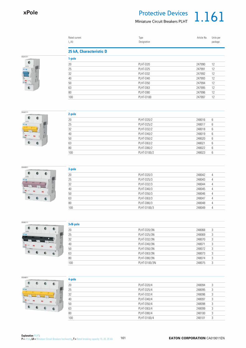
1.161
161 EATON CORPORATION CA019011EN
Protective DevicesMiniature Circuit Breakers PLHT
Rated currentIn (A)
TypeDesignation
Article No. Units perpackage
25 kA, Characteristic DSG41311
20 PLHT-D20 247990 1225 PLHT-D25 247991 1232 PLHT-D32 247992 1240 PLHT-D40 247993 1250 PLHT-D50 247994 1263 PLHT-D63 247995 1280 PLHT-D80 247996 12100 PLHT-D100 247997 12
1-pole
SG42111
20 PLHT-D20/2 248016 625 PLHT-D25/2 248017 632 PLHT-D32/2 248018 640 PLHT-D40/2 248019 650 PLHT-D50/2 248020 663 PLHT-D63/2 248021 680 PLHT-D80/2 248022 6100 PLHT-D100/2 248023 6
2-pole
SG42911
20 PLHT-D20/3 248042 425 PLHT-D25/3 248043 432 PLHT-D32/3 248044 440 PLHT-D40/3 248045 450 PLHT-D50/3 248046 463 PLHT-D63/3 248047 480 PLHT-D80/3 248048 4100 PLHT-D100/3 248049 4
3-pole
SG45111
20 PLHT-D20/3N 248068 325 PLHT-D25/3N 248069 332 PLHT-D32/3N 248070 340 PLHT-D40/3N 248071 350 PLHT-D50/3N 248072 363 PLHT-D63/3N 248073 380 PLHT-D80/3N 248074 3100 PLHT-D100/3N 248075 3
3+N-pole
SG44811
20 PLHT-D20/4 248094 325 PLHT-D25/4 248095 332 PLHT-D32/4 248096 340 PLHT-D40/4 248097 350 PLHT-D50/4 248098 363 PLHT-D63/4 248099 380 PLHT-D80/4 248100 3100 PLHT-D100/4 248101 3
4-pole
Explanation PLHT: P = xPole, LH = Miniature Circuit Breakers hochwertig, T = Rated breaking capacity 15, 20, 25 kA
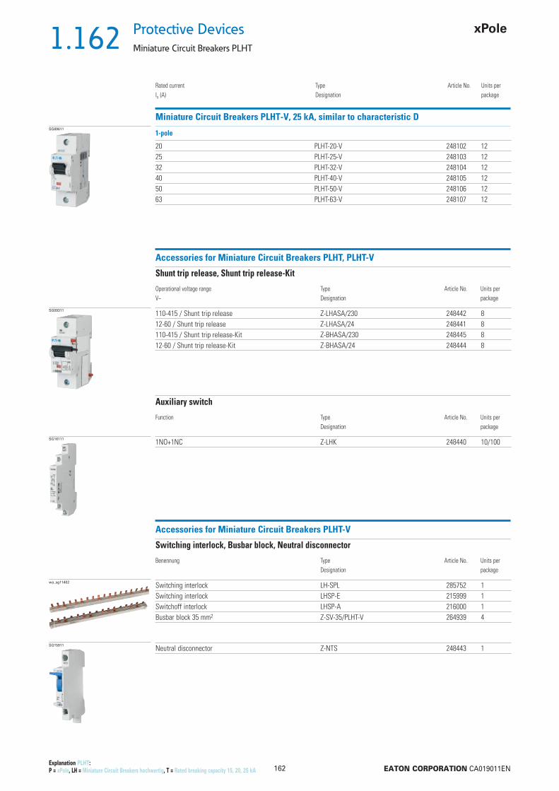
1.162
162 EATON CORPORATION CA019011EN
Protective Devices
Miniature Circuit Breakers PLHT
Rated currentIn (A)
TypeDesignation
Article No. Units perpackage
Miniature Circuit Breakers PLHT-V, 25 kA, similar to characteristic DSG69611
20 PLHT-20-V 248102 1225 PLHT-25-V 248103 1232 PLHT-32-V 248104 1240 PLHT-40-V 248105 1250 PLHT-50-V 248106 1263 PLHT-63-V 248107 12
1-pole
Explanation PLHT: P = xPole, LH = Miniature Circuit Breakers hochwertig, T = Rated breaking capacity 15, 20, 25 kA
Accessories for Miniature Circuit Breakers PLHT, PLHT-V
SG09311 110-415 / Shunt trip release Z-LHASA/230 248442 812-60 / Shunt trip release Z-LHASA/24 248441 8110-415 / Shunt trip release-Kit Z-BHASA/230 248445 812-60 / Shunt trip release-Kit Z-BHASA/24 248444 8
Operational voltage rangeV~
TypeDesignation
Article No. Units perpackage
Shunt trip release, Shunt trip release-Kit
SG16111 1NO+1NC Z-LHK 248440 10/100
Function TypeDesignation
Article No. Units perpackage
Auxiliary switch
Accessories for Miniature Circuit Breakers PLHT-V
wa_sg11402 Switching interlock LH-SPL 285752 1Switching interlock LHSP-E 215999 1Switchoff interlock LHSP-A 216000 1Busbar block 35 mm2 Z-SV-35/PLHT-V 264939 4
Benennung TypeDesignation
Article No. Units perpackage
Switching interlock, Busbar block, Neutral disconnector
SG15911 Neutral disconnector Z-NTS 248443 1

1.163
163 EATON CORPORATION CA019011EN
Protective DevicesMiniature Circuit Breakers PLHT - Technical Data
Specifi cations | Miniature Circuit Breakers PLHT
Description
• Independent switching contacts• With isolator function, meets the requirements of insulation co-ordination,
distance between contacts 4 mm, for secure isolation
Accessories:Auxiliary switch for subsequent installation (0.5 MU) Z-LHK 248440Shunt trip release subsequent installation (1.5 MU) Z-LHASA/230 248442
Z-LHASA/24 248441Switching interlock LH-SPL 285752
Busbars: see capter busbar systems
Technical DataPLHT
ElectricalDesign according toCurrent test marks as printed onto the device
EN 60947-2
Rated voltage Un AC: 230/400 VDC: 60 V (per pole, max. 2 poles)
Ultimate short circuit breaking capacity according to IEC/EN 60947-2Characteristic B, C In = 20-63 A: 25 kA
In = 80-100 A: 20 kAIn = 125 A: 15 kA
Characteristic D In = 20-63 A: 25 kAIn = 80 A: 20 kAIn = 100 A: 15 kA
Characteristic in accordance with B, C, DBack-up fuse max. 200 A gLRated insulation voltage 440 VPeak withstand voltage Uimp 4 kVSelectivity class in accordance with class 3Endurance 20,000 switching operationsMechanicalFrame size 45 mmDevice height 90 mmDevice width 27 mm (1.5MU) per poleMounting quick fastening with 2 lock-in positions on DIN rail IEC/EN 60715Degree of protection IP20Degree of protection, built-in IP40Upper and lower terminals lift terminalsTerminal protection fi nger and hand touch safe, DGUV VS3, EN 50274Terminal capacity 2.5-50 mm2
Connection diagrams1-pole 2-pole 3-pole 3+N-pole 4-pole

1.164
164 EATON CORPORATION CA019011EN
Protective Devices
Miniature Circuit Breakers PLHT - Technical Data
Dimensions (mm)
Load Capacity
Durchlassenergie
Determined according to 60898-1.
Maximum let-through energy PLHT, Characteristic C, 1-pole Maximum let-through energy PLHT, Characteristic D, 1-pole
Load capacity in case of block installation Effect of ambient temperature
Permitted permanent load at ambient temperature T [°C] with n devices: IDL = InKT(T)KN(N).
Ambient temperature T [°C]
Load
cap
acity
KT
[I/In
]
Number of devices (n) 1-pole
Load
cap
acity
fac
tor
KN
Prospective short-circuit current [A]
Let
thro
ugh
ener
gy I2
t [A
2 se
c]
Prospective short-circuit current [A]
Let
thro
ugh
ener
gy I2
t [A
2 se
c]

1.165
165 EATON CORPORATION CA019011EN
Protective DevicesMiniature Circuit Breakers PLHT - Technical Data
Short Circuit Selectivity PLHT towards D01, D02, D03 and NH size 00
Selectivity towards back-up fuses D01, D02, D03
• Short circuit selectivity (in kA) PLHT and upstream fuse D0 or NH, operating class gL/gG• . . . selectivity up to 1.4 kA; Darker areas: no selectivity1.4
Selectivity towards back-up fuses NH size 00
PLHT Rated current of the back-up fuse in A gL/gGIn [A] 25 35 50 63 80 10020 0.5 1.0 2.0 2.9 3.9 7.625 1.0 1.9 2.8 3.8 7.332 1.0 1.8 2.7 3.6 7.040 1.6 2.2 3.0 5.650 2.1 2.8 5.263 2.7 4.880 4.3100125
Characteristic C Characteristic D
PLHT Rated current of the back-up fuse in A gL/gGIn [A] 25 35 40 50 63 80 100 125 160 20020 0.5 1.0 1.3 1.9 2.7 3.7 6.7 17.0 25.0 25.025 0.9 1.3 1.8 2.6 3.5 6.5 17.0 25.0 25.032 0.9 1.2 1.7 2.4 3.3 6.0 15.0 23.0 25.040 1.4 2.1 2.9 4.8 12.0 18.0 25.050 1.9 2.7 4.5 11.0 17.0 25.063 4.2 10.0 15.0 25.080 3.8 8.5 12.0 25.0100 7.0 10.0 25.0125 7.5 25.0
Characteristic C Characteristic D
PLHT Rated current of the back-up fuse in A gL/gGIn [A] 25 35 50 63 80 10020 0.5 0.9 1.7 2.5 3.4 6.725 0.9 1.6 2.3 3.2 6.232 0.9 1.5 2.3 3.0 6.040 1.4 2.0 2.6 4.750 1.8 2.3 4.363 2.1 3.780 3.1100
PLHT Rated current of the back-up fuse in A gL/gGIn [A] 25 35 40 50 63 80 100 125 160 20020 <0.5 0.8 1.1 1.5 2.3 3.1 5.6 16.0 25.0 25.025 0.7 1.0 1.4 2.1 3.0 5.3 14.0 23.0 25.032 0.7 1.0 1.3 2.1 2.9 5.0 13.0 22.0 25.040 1.1 1.8 2.5 4.2 10.0 15.0 25.050 1.6 2.3 3.8 8.5 13.0 22.063 2.1 3.2 7.0 10.5 18.080 2.8 5.5 8.4 15.0100 4.8 7.5 12.5

1.166
166 EATON CORPORATION CA019011EN
Protective Devices
Miniature Circuit Breakers PLHT - Technical Data
Short Circuit Selectivity PLHT towards NZMIn case of short circuit, there is selectivity between the miniature circuit breakers PLHT and the upstream NZM up to the specifi ed values of the selectivity limit current Is [kA] (i. e. in case of short-circuit currents Iks under Is only the MCB will trip, in case of short circuit currents above this value both protective devices will respond). Overload and short-circuit release unit NZM at max. value.*) basically in accordance with EN 60898-1 D.5.2.b
Short circuit selectivity Characteristic C towards NZM1*) Short circuit selectivity Characteristic D towards NZM1*)
PLHT NZM...1-A gL/gGIn [A] 40 50 63 80 100 12520 0.3 0.4 0.5 0.75 0.9 1.2525 0.3 0.4 0.5 0.7 0.9 1.232 0.4 0.5 0.7 0.85 1.240 0.5 0.6 0.85 1.150 0.6 0.85 1.163 0.8 180 1100125
1) Selectivity limit current Is under 0.5 kA2) Selectivity limit current Is = rated breaking capacity Icn of the MCBDarker areas: no selectivity
PLHT NZM...1-A gL/gGIn [A] 40 50 63 80 100 125506380100
Short circuit selectivity Characteristic C towards NZM2*) Short circuit selectivity Characteristic D towards NZM2*)
PLHT NZM...2-A gL/gGIn [A] 40 50 63 80 100 125 160 200 25020 0.3 0.4 0.5 0.75 0.9 1.25 1.8 2.5 3.525 0.3 0.4 0.5 0.7 0.9 1.2 1.7 2.4 3.332 0.4 0.5 0.7 0.85 1.2 1.65 2.3 3.240 0.5 0.6 0.85 1.1 1.5 2.1 2.950 0.6 0.85 1.1 1.5 2 2.863 0.8 1 1.4 1.8 2.580 1 1.4 1.8 2.4100 1.3 1.7 2.3125 1.6 2.1
PLHT NZM...2-A gL/gGIn [A] 40 50 63 80 100 125 160 200 25050 1 1.4 2.663 1 1.3 2.380 2.1100

1.167
167 EATON CORPORATION CA019011EN
Protective DevicesMiniature Circuit Breakers PLHT-V - Technical Data
Specifi cations | Miniature Circuit Breakers PLHT-V
Description
• Special type of miniature circuit breaker PLHT for trade and industry applica-tions upstream of the meter
• Independent switching contacts• High current limit• With isolator function, meets the requirements of insulation co-ordination,
distance between contacts 4 mm, for secure isolation• Anti-Tamper device and Switchoff interlock available
Accessories:Auxiliary switch for subsequent installation (0.5 MU) Z-LHK 248440Shunt trip release subsequent installation (1.5 MU) Z-LHASA/230 248442
Z-LHASA/24 248441Neutral disconnector Z-NTS 248443
Busbars: see capter busbar systems
Technical DataPLHT-V
ElectricalDesign according toCurrent test marks as printed onto the device
EN 60947-2
Rated voltage Un AC: 230/400 VDC: 60 V (per pole, max. 2 poles)
Ultimate short circuit breaking capacity according to IEC/EN 60947-2 25 kAService short circuit breaking capacity 20 kARated breaking capacity DC: max. 60 V, 1-poleCharacteristic similar to DBack-up fuse max. 200 A gL (>20 kA)Rated insulation voltage 440 VPeak withstand voltage Uimp 4 kVSelectivity class in accordance with class 3Endurance 20,000 switching operationsMechanicalFrame size 45 mmDevice height 90 mmDevice width 27 mm (1.5MU) per pole, 30 mm per pole PLHT-V with interlockMounting quick fastening with 2 lock-in positions on DIN rail IEC/EN 60715Degree of protection IP20Degree of protection, built-in IP40Upper and lower terminals lift terminalsTerminal protection fi nger and hand touch safe, DGUV VS3, EN 50274Terminal capacity 2.5-50 mm2
Connection diagram1-pole
Dimensions (mm)

1.168
168 EATON CORPORATION CA019011EN
Protective Devices
Miniature Circuit Breakers PLHT - Technical Data
Specifi cations | Accessories for PLHT, PLHT-V
Shunt trip release Z-LHASA
• Can be mounted subsequently• Contact position indicator red/green• Marking labels can be fi tted• Wide operational voltage range• Suffi cient power of extra low voltage source must be ensured
Z-LHASA/24: min. 90 VA
Technical Data
Z-LHASAElectricalOperational voltage range
Z-LHASA/230 110-415 V~Z-LHASA/24 12-60 V~
Operational frequency 50-60 HzMaximum current consumption during switch-on at Un
Z-LHASA/230 2 AZ-LHASA/24 18 A
MechanicalFrame size 45 mmDevice height 90 mmDevice width 27 mmMounting quick fastening with 2 lock-in positions on DIN rail IEC/EN 60715Degree of protection IP20Degree of protection, built-in IP40Upper and lower terminals lift terminals
Dimensions (mm)

1.169
169 EATON CORPORATION CA019011EN
Protective DevicesMiniature Circuit Breakers PLHT - Technical Data
Auxiliary switch Z-LHK
• Auxiliary switch according to IEC 947-5-1• Can be mounted subsequently
Technical Data
Z-LHKElectricalRated operational current (250 V~) 6 A / AC13Minimum operational voltage 24 V each lineRated thermal current 8 ARated insulation voltage 440 V~Maximum back-up fuse 6 A gL or CLS6-4/./B-HSContacts 1NO+1NCUtilisation category AC13 6 A / 250 VAC
2 A / 440 VACUtilisation category DC13 4 A / 60 VDC
2 A / 110 VDC0,5 A / 230 VDC
MechanicalFrame size 45 mmDevice height 90 mmDevice width 9 mmMounting mounted onto protective devicesDegree of protection, built-in IP40Upper and lower terminals lift terminalsTerminal capacity 1 x 1 mm2 to 2 x 2.5 mm2
Connection diagram
Dimensions (mm)
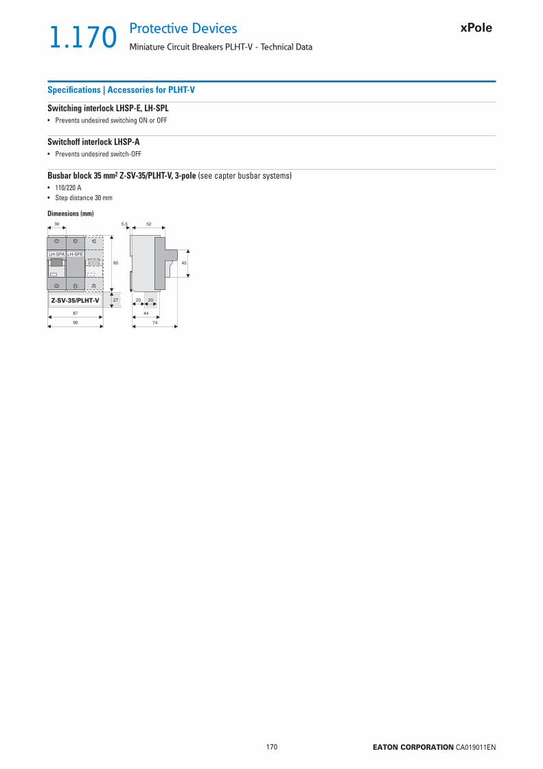
1.170
170 EATON CORPORATION CA019011EN
Protective Devices
Miniature Circuit Breakers PLHT-V - Technical Data
Specifi cations | Accessories for PLHT-V
Switching interlock LHSP-E, LH-SPL• Prevents undesired switching ON or OFF
Switchoff interlock LHSP-A• Prevents undesired switch-OFF
Busbar block 35 mm2 Z-SV-35/PLHT-V, 3-pole (see capter busbar systems)• 110/220 A• Step distance 30 mm
Dimensions (mm)
Z-SV-35/PLHT-V
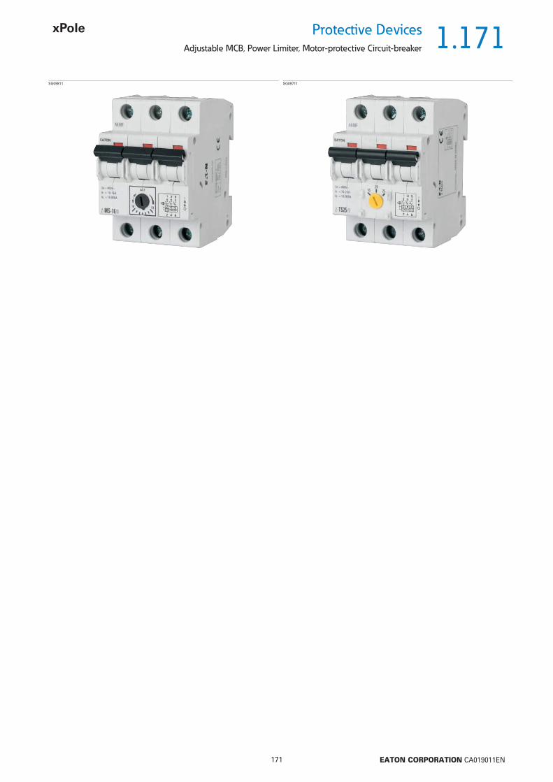
1.171
171 EATON CORPORATION CA019011EN
Protective DevicesAdjustable MCB, Power Limiter, Motor-protective Circuit-breaker
SG09811 SG09711

1.172
172 EATON CORPORATION CA019011EN
Protective Devices
Adjustable MCB, Power Limiter, Motor-protective Circuit-breaker
Setting Range(A)
TypeDesignation
Article No. Units perpackage
Adjustable MCB Z-MSSG09911
0.10 - 0.16 Z-MS-0.16/2 248389 1/600.16 - 0.25 Z-MS-0,25/2 248390 1/600.25 - 0.40 Z-MS-0,4/2 248391 1/600.40 - 0.63 Z-MS-0,63/2 248392 1/600.63 - 1.00 Z-MS-1/2 248393 1/601.00 - 1.60 Z-MS-1,6/2 248394 1/601.60 - 2.50 Z-MS-2,5/2 248395 1/602.50 - 4.00 Z-MS-4/2 248396 1/604.00 - 6.30 Z-MS-6,3/2 248397 1/606.30 - 10.0 Z-MS-10/2 248398 1/6010.0 - 16.0 Z-MS-16/2 248399 1/6016.0 - 25.0 Z-MS-25/2 248400 1/6025.0 - 40.0 Z-MS-40/2 248401 1/60
2-pole
SG09811
0.10 - 0.16 Z-MS-0.16/3 248402 1/400.16 - 0.25 Z-MS-0,25/3 248403 1/400.25 - 0.40 Z-MS-0,4/3 248404 1/400.40 - 0.63 Z-MS-0,63/3 248405 1/400.63 - 1.00 Z-MS-1/3 248406 1/401.00 - 1.60 Z-MS-1,6/3 248407 1/401.60 - 2.50 Z-MS-2,5/3 248408 1/402.50 - 4.00 Z-MS-4/3 248409 1/404.00 - 6.30 Z-MS-6,3/3 248410 1/406.30 - 10.0 Z-MS-10/3 248411 1/4010.0 - 16.0 Z-MS-16/3 248412 1/4016.0 - 25.0 Z-MS-25/3 248413 1/4025.0 - 40.0 Z-MS-40/3 248414 1/40
3-pole
Rated CurrentIn (A)
Setting Range(A)
TypeDesignation
Article No. Units perpackage
Power Limiter Z-TSSG09611
20 13-20 Z-TS20/1 266850 225 16-25 Z-TS25/1 266852 232 20-32 Z-TS32/1 266853 240 25-40 Z-TS40/1 266854 250 40-50 Z-TS50/1 266855 263 50-63 Z-TS63/1 266856 2
1-pole, 230 V~
SG09711
20 13-20 Z-TS20/3 266857 125 16-25 Z-TS25/3 266858 132 20-32 Z-TS32/3 266859 140 25-40 Z-TS40/3 266860 150 40-50 Z-TS50/3 266861 163 50-63 Z-TS63/3 266862 1
3-pole, 400 V~
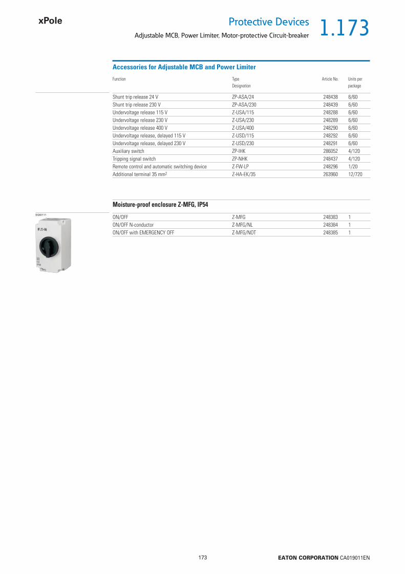
1.173
173 EATON CORPORATION CA019011EN
Protective DevicesAdjustable MCB, Power Limiter, Motor-protective Circuit-breaker
Accessories for Adjustable MCB and Power Limiter
Shunt trip release 24 V ZP-ASA/24 248438 6/60Shunt trip release 230 V ZP-ASA/230 248439 6/60Undervoltage release 115 V Z-USA/115 248288 6/60Undervoltage release 230 V Z-USA/230 248289 6/60Undervoltage release 400 V Z-USA/400 248290 6/60Undervoltage release, delayed 115 V Z-USD/115 248292 6/60Undervoltage release, delayed 230 V Z-USD/230 248291 6/60Auxiliary switch ZP-IHK 286052 4/120Tripping signal switch ZP-NHK 248437 4/120Remote control and automatic switching device Z-FW-LP 248296 1/20Additional terminal 35 mm2 Z-HA-EK/35 263960 12/720
Function TypeDesignation
Article No. Units perpackage
Moisture-proof enclosure Z-MFG, IP54SG82111 ON/OFF Z-MFG 248383 1
ON/OFF N-conductor Z-MFG/NL 248384 1ON/OFF with EMERGENCY OFF Z-MFG/NOT 248385 1

1.174
174 EATON CORPORATION CA019011EN
Protective Devices
Adjustable MCB Z-MS - Technical Data
Specifi cations | Adjustable MCB Z-MS
Description
• Reliable protection in case of thermal overload and short circuit• Suitable for installation in compact distribution boxes• Contact position indicator red - green• Main fi eld of application: switching and protection of three-phase AC motors
with power ratings up to 15 kW (380/400 V) and other consumers up to 40 A• Also suitable as main switch, isolating characteristics according to
IEC/EN 60947• All manual motor starters with thermal overload tripping and magnetic short-
circuit tripping• Terminals and accessories compatible with CLS6, Z-A40, PFIM etc.
Technical DataZ-MS
GeneralTerminal capacity 1 - 25 mm2
Busbar thickness 0.8-2 mmEndurance mechanical components 20,000 switching operationsShock resistance (shock duration 20 ms) 20 gAmbient temperature
open -25 ... + 50 °Chermetically enclosed -25 ... + 40 °C
Resistance to climatic conditionshumidity and heat, constant, according to IEC 68-2-3humidity and heat, periodical, according to IEC 68-2-30
Weight approx.2-pole 244 g3-pole 366 g
Degree of protection IP20Main Current PathsRated insulation voltage Ui 440 VRated impulse withstand voltage Uimp 4 kVRated short circuit breaking capacity Iq 10 kAThermal current Ith max = Ie max 40 AElectrical endurance AC3 and Ie 6,000 switching operationsMotor switching capacity AC3 400 (415) VPower loss per contact
1.6-10 A 2.3 W16 A 3.3 W25-40 A 4.5 W
Operating frequency 50/60 HzAuxiliary switch Z-AHK/Z-NHKRated insulation voltage Ui 440 VThermal current Ith 8 ARated operational current Ie
250 V 6 Awith AC 13, 440 V 2 A
Max. back-up fuse for short-circuit protection 4 A (gL, gG) CLS6-4/B-HSTerminal capacity (1 or 2 conductors) 0.75 ... 2.5 mm2
Moisture-Proof Enclosure 4 MU IP54, Z-MFGReliable power loss of incorporated devices 17W (e.g. Z-MS-40/3+Z-USA/230)
Connection diagram2-pole 3-pole
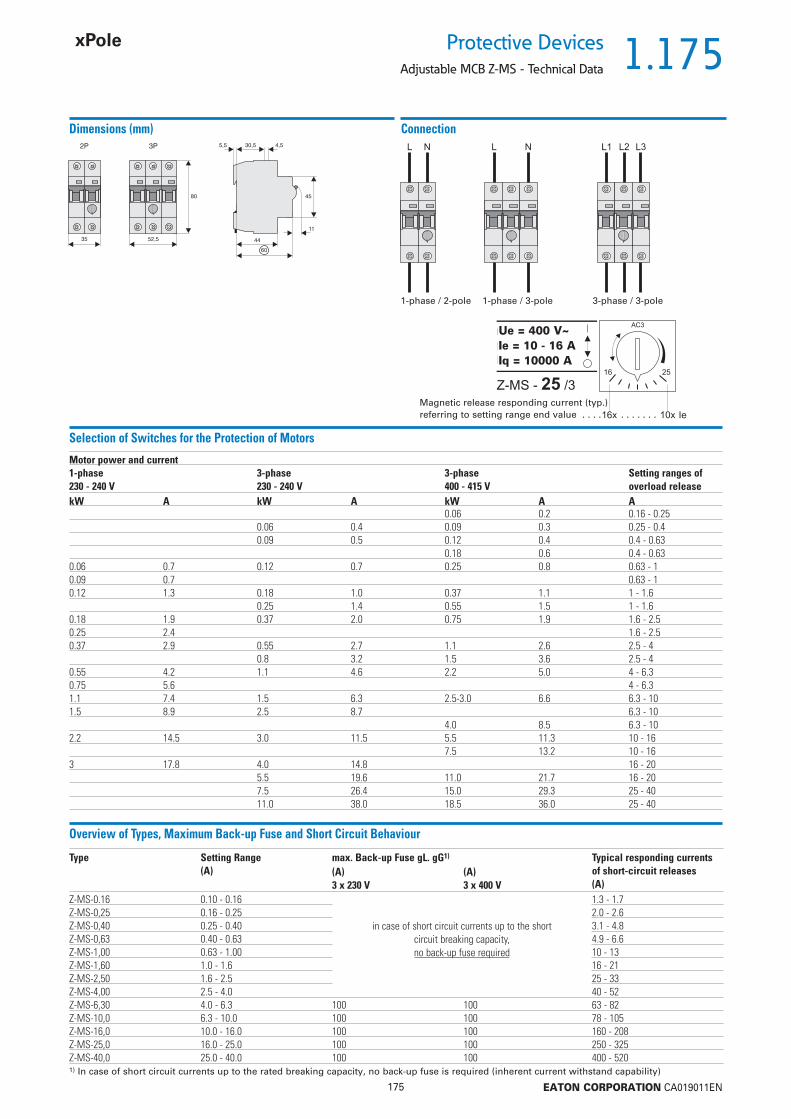
1.175
175 EATON CORPORATION CA019011EN
Protective DevicesAdjustable MCB Z-MS - Technical Data
Dimensions (mm) Connection
Selection of Switches for the Protection of Motors
Overview of Types, Maximum Back-up Fuse and Short Circuit Behaviour
Motor power and current1-phase230 - 240 V
3-phase230 - 240 V
3-phase400 - 415 V
Setting ranges of overload release
kW A kW A kW A A0.06 0.2 0.16 - 0.25
0.06 0.4 0.09 0.3 0.25 - 0.40.09 0.5 0.12 0.4 0.4 - 0.63
0.18 0.6 0.4 - 0.630.06 0.7 0.12 0.7 0.25 0.8 0.63 - 10.09 0.7 0.63 - 10.12 1.3 0.18 1.0 0.37 1.1 1 - 1.6
0.25 1.4 0.55 1.5 1 - 1.60.18 1.9 0.37 2.0 0.75 1.9 1.6 - 2.50.25 2.4 1.6 - 2.50.37 2.9 0.55 2.7 1.1 2.6 2.5 - 4
0.8 3.2 1.5 3.6 2.5 - 40.55 4.2 1.1 4.6 2.2 5.0 4 - 6.30.75 5.6 4 - 6.31.1 7.4 1.5 6.3 2.5-3.0 6.6 6.3 - 101.5 8.9 2.5 8.7 6.3 - 10
4.0 8.5 6.3 - 102.2 14.5 3.0 11.5 5.5 11.3 10 - 16
7.5 13.2 10 - 163 17.8 4.0 14.8 16 - 20
5.5 19.6 11.0 21.7 16 - 207.5 26.4 15.0 29.3 25 - 4011.0 38.0 18.5 36.0 25 - 40
Type Setting Range (A)
max. Back-up Fuse gL. gG1) Typical responding currents of short-circuit releases (A)
(A)3 x 230 V
(A)3 x 400 V
Z-MS-0.16 0.10 - 0.16
in case of short circuit currents up to the short circuit breaking capacity,no back-up fuse required
1.3 - 1.7Z-MS-0,25 0.16 - 0.25 2.0 - 2.6Z-MS-0,40 0.25 - 0.40 3.1 - 4.8Z-MS-0,63 0.40 - 0.63 4.9 - 6.6Z-MS-1,00 0.63 - 1.00 10 - 13Z-MS-1,60 1.0 - 1.6 16 - 21Z-MS-2,50 1.6 - 2.5 25 - 33Z-MS-4,00 2.5 - 4.0 40 - 52Z-MS-6,30 4.0 - 6.3 100 100 63 - 82Z-MS-10,0 6.3 - 10.0 100 100 78 - 105Z-MS-16,0 10.0 - 16.0 100 100 160 - 208Z-MS-25,0 16.0 - 25.0 100 100 250 - 325Z-MS-40,0 25.0 - 40.0 100 100 400 - 5201) In case of short circuit currents up to the rated breaking capacity, no back-up fuse is required (inherent current withstand capability)
1-phase / 2-pole 1-phase / 3-pole 3-phase / 3-pole
Magnetic release responding current (typ.) referring to setting range end value . . . . . . . . . . .
Ue = 400 V~Ie = 10 - 16 AIq = 10000 A
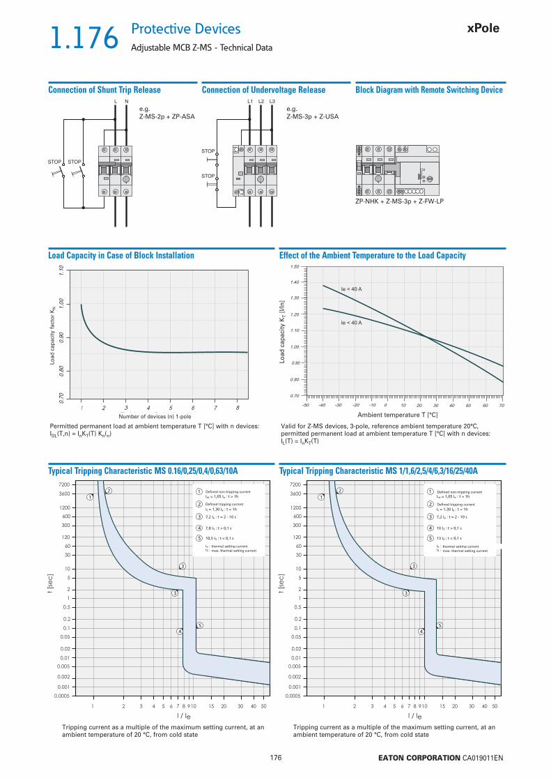
1.176
176 EATON CORPORATION CA019011EN
Protective Devices
Adjustable MCB Z-MS - Technical Data
Connection of Shunt Trip Release
e.g. Z-MS-2p + ZP-ASA
Connection of Undervoltage Release
e.g. Z-MS-3p + Z-USA
Block Diagram with Remote Switching Device
ZP-NHK + Z-MS-3p + Z-FW-LP
Typical Tripping Characteristic MS 0.16/0,25/0,4/0,63/10A
Tripping current as a multiple of the maximum setting current, at an ambient temperature of 20 °C, from cold state
Effect of the Ambient Temperature to the Load CapacityLoad Capacity in Case of Block Installation
Typical Tripping Characteristic MS 1/1,6/2,5/4/6,3/16/25/40A
Tripping current as a multiple of the maximum setting current, at an ambient temperature of 20 °C, from cold state
Valid for Z-MS devices, 3-pole, reference ambient temperature 20°C,permitted permanent load at ambient temperature T [°C] with n devices: IL(T) = InKT(T)
Permitted permanent load at ambient temperature T [°C] with n devices: IDL(T,n) = InKT(T) Kn(n)
Ambient temperature T [°C]
Load
cap
acity
KT
[I/In
]
Number of devices (n) 1-pole
Load
cap
acity
fac
tor
KN
Defi ned non-tripping current
Defi ned tripping current
Defi ned non-tripping current
Defi ned tripping current
thermal setting currentmax. thermal setting current
thermal setting currentmax. thermal setting current
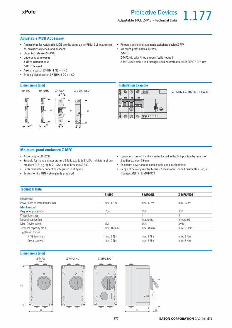
1.177
177 EATON CORPORATION CA019011EN
Protective DevicesAdjustable MCB Z-MS - Technical Data
Adjustable MCB Accessory
• Accessories for Adjustable MCB are the same as for PFIM, CLS etc. (releas-es, auxiliary switches, and busbars
• Shunt trip release ZP-ASA• Undervoltage releases
Z-USA: instantaneousZ-USD: delayed
• Auxiliary switch ZP-IHK: 1 NO + 1 NC• Tripping signal switch ZP-NHK: 1 CO + 1 CO
• Remote control and automatic switching device Z-FW• Moisture-proof enclosure IP54
Z-MFGZ-MFG/NL: with N-led through (solid neutral)Z-MFG/NOT: with N-led through (solid neutral) and EMERGENCY OFF key
Dimensions (mm)ZP-IHK ZP-ASA Z-USA, -USDZP-NHK
Installation Example
ZP-NHK + Z-MS-2p + Z-FW-LP
Moisture-proof enclosure Z-MFG
• According to EN 50298• Suitable for manual motor starters Z-MS, e.g. 3p (+ Z-USA); miniature circuit
breakers CLS, e.g. 3p (+ Z-USA); circuit breakers Z-A40• Earth conductor connection integrated in all types• Entries for 4 x PG16 cable glands prepared
• Operation: Turning handle, can be locked in the OFF-position by means of 3 padlocks, max. Ø 6 mm
• Enclosure cover can be sealed with leads in 2 locations• Scope of delivery: 4 entry bushes, 1 mushroom-shaped pushbutton (red) +
1 contact (NC) in Z-MFG/NOT
Technical DataZ-MFG Z-MFG/NL Z-MFG/NOT
ElectricalPower Loss of installed devices max. 17 W max. 17 W max. 17 WMechanicalDegree of protection IP54 IP54 IP54Protection class II II IINeutral connection - integrated integratedMax. Device width 4MU 4MU 4MUTerminal capacity N/PE max. 16 mm2 max. 16 mm2 max. 16 mm2
Tightening torqueN/PE terminals max. 2 Nm max. 2 Nm max. 2 NmCover screws max. 2 Nm max. 2 Nm max. 2 Nm
Dimensions (mm)Z-MFG Z-MFG/NL Z-MFG/NOT
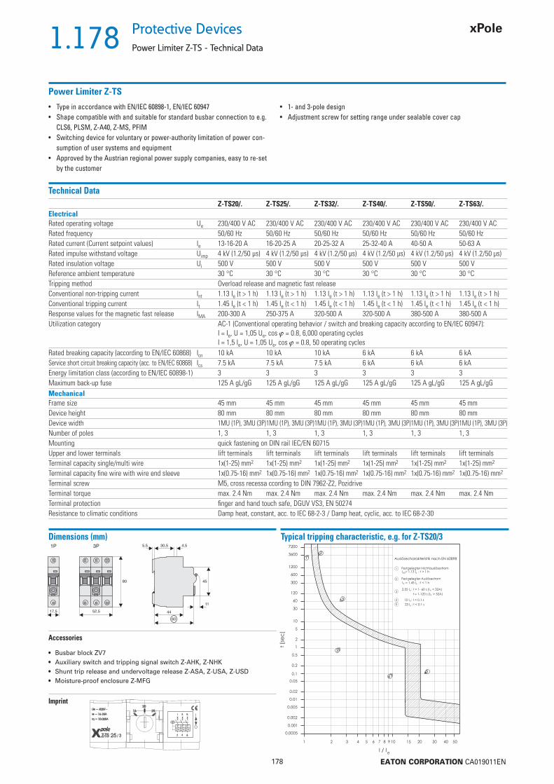
1.178
178 EATON CORPORATION CA019011EN
Protective Devices
Power Limiter Z-TS - Technical Data
Power Limiter Z-TS
• Type in accordance with EN/IEC 60898-1, EN/IEC 60947• Shape compatible with and suitable for standard busbar connection to e.g.
CLS6, PLSM, Z-A40, Z-MS, PFIM• Switching device for voluntary or power-authority limitation of power con-
sumption of user systems and equipment• Approved by the Austrian regional power supply companies, easy to re-set
by the customer
• 1- and 3-pole design• Adjustment screw for setting range under sealable cover cap
Technical DataZ-TS20/. Z-TS25/. Z-TS32/. Z-TS40/. Z-TS50/. Z-TS63/.
ElectricalRated operating voltage Ue 230/400 V AC 230/400 V AC 230/400 V AC 230/400 V AC 230/400 V AC 230/400 V ACRated frequency 50/60 Hz 50/60 Hz 50/60 Hz 50/60 Hz 50/60 Hz 50/60 HzRated current (Current setpoint values) Ie 13-16-20 A 16-20-25 A 20-25-32 A 25-32-40 A 40-50 A 50-63 ARated impulse withstand voltage Uimp 4 kV (1.2/50 μs) 4 kV (1.2/50 μs) 4 kV (1.2/50 μs) 4 kV (1.2/50 μs) 4 kV (1.2/50 μs) 4 kV (1.2/50 μs)Rated insulation voltage Ui 500 V 500 V 500 V 500 V 500 V 500 VReference ambient temperature 30 °C 30 °C 30 °C 30 °C 30 °C 30 °CTripping method Overload release and magnetic fast releaseConventional non-tripping current Int 1.13 Ie (t > 1 h) 1.13 Ie (t > 1 h) 1.13 Ie (t > 1 h) 1.13 Ie (t > 1 h) 1.13 Ie (t > 1 h) 1.13 Ie (t > 1 h)Conventional tripping current It 1.45 Ie (t < 1 h) 1.45 Ie (t < 1 h) 1.45 Ie (t < 1 h) 1.45 Ie (t < 1 h) 1.45 Ie (t < 1 h) 1.45 Ie (t < 1 h)Response values for the magnetic fast release IMA 200-300 A 250-375 A 320-500 A 320-500 A 380-500 A 380-500 AUtilization category AC-1 (Conventional operating behavior / switch and breaking capacity according to EN/IEC 60947):
I = Ie, U = 1,05 Ue, cos = 0.8, 6,000 operating cyclesI = 1,5 Ie, U = 1,05 Ue, cos = 0.8, 50 operating cycles
Rated breaking capacity (according to EN/IEC 60868) Icn 10 kA 10 kA 10 kA 6 kA 6 kA 6 kAService short circuit breaking capacity (acc. to EN/IEC 60868) Ics 7.5 kA 7.5 kA 7.5 kA 6 kA 6 kA 6 kAEnergy limitation class (according to EN/IEC 60898-1) 3 3 3 3 3 3Maximum back-up fuse 125 A gL/gG 125 A gL/gG 125 A gL/gG 125 A gL/gG 125 A gL/gG 125 A gL/gGMechanicalFrame size 45 mm 45 mm 45 mm 45 mm 45 mm 45 mmDevice height 80 mm 80 mm 80 mm 80 mm 80 mm 80 mmDevice width 1MU (1P), 3MU (3P)1MU (1P), 3MU (3P)1MU (1P), 3MU (3P)1MU (1P), 3MU (3P)1MU (1P), 3MU (3P)1MU (1P), 3MU (3P)Number of poles 1, 3 1, 3 1, 3 1, 3 1, 3 1, 3Mounting quick fastening on DIN rail IEC/EN 60715Upper and lower terminals lift terminals lift terminals lift terminals lift terminals lift terminals lift terminalsTerminal capacity single/multi wire 1x(1-25) mm2 1x(1-25) mm2 1x(1-25) mm2 1x(1-25) mm2 1x(1-25) mm2 1x(1-25) mm2
Terminal capacity fi ne wire with wire end sleeve 1x(0.75-16) mm2 1x(0.75-16) mm2 1x(0.75-16) mm2 1x(0.75-16) mm2 1x(0.75-16) mm2 1x(0.75-16) mm2
Terminal screw M5, cross recessa ccording to DIN 7962-Z2, PozidriveTerminal torque max. 2.4 Nm max. 2.4 Nm max. 2.4 Nm max. 2.4 Nm max. 2.4 Nm max. 2.4 NmTerminal protection fi nger and hand touch safe, DGUV VS3, EN 50274Resistance to climatic conditions Damp heat, constant, acc. to IEC 68-2-3 / Damp heat, cyclic, acc. to IEC 68-2-30
Dimensions (mm)
Accessories
• Busbar block ZV7• Auxiliary switch and tripping signal switch Z-AHK, Z-NHK• Shunt trip release and undervoltage release Z-ASA, Z-USA, Z-USD• Moisture-proof enclosure Z-MFG
Typical tripping characteristic, e.g. for Z-TS20/3
Imprint

2.179
179 EATON CORPORATION CA019011EN
Accessories for Protective DevicesAccessories for RCDs, MCBs, Combined RCD/MCB Devices
• SWD Auxiliary Module
• Auxiliary Switch
• RCD-Tripping Module
• Shunt Trip Release
• Undervoltage Release
• Remote Control and Automatic Switching
Device
• Switching Interlocks
• Terminal Covers
Description
SG30811 SG60811

2.180
180 EATON CORPORATION CA019011EN
Accessories for Protective Devices
Auxiliary Switch Z-HK, Z-AHK, Z-HD; Tripping Signal Switch Z-NHK
Design: for screwingSG34812 RCCB / 1NO+1NC Z-HK 248432 4/120
For Protective Device / Function Type Article No. Units perDesignation package
SG60911 MCB, RCBO (1+N, 3P, 3+N) / 1NO+1NC Z-AHK 248433 4/120
SG61011 MCB, RCBO, RCCB / 2CO Z-NHK 248434 4/120
SG34412 RCCB / 1CO+1NC Z-HD 265620 1
Description Auxiliary Switch Z-HK, Z-AHK; Tripping Signal Switch Z-NHK
• Design according to IEC/EN 60947-5-1, IEC/EN 62019• Can be mounted subsequently (screws) onto FRCmM, FRCdM• The specifi ed minimum voltages are per contact.
Take into account particularly in case of series connection!
• Z-AHK, Z-NHK: Contact function with relative movement (selfcleaning contacts)• Contact material and design particularly suitable for extra low voltage
• Z-NHK: The function of one of the two change-over contacts can be switched from “auxiliary switch” to “tripping signal switch”• Tripping signal contact transmits message of electric tripping, not mechanical switch-off• Test key for contact function “electrical tripping”

2.181
181 EATON CORPORATION CA019011EN
Accessories for Protective DevicesAuxiliary Switch Z-HK, Z-AHK, Z-HD; Tripping Signal Switch Z-NHK
Technical DataZ-HK Z-AHK Z-NHK
ElectricalContact function 1NO + 1NC 1NO + 1NC 2CORated voltage 250 V 250 V 250 VFrequency 50/60 Hz 50/60 Hz 50/60 HzRated current 8 A 4 A 4 ARated thermal current Ith 8 A 4 A 4 AUtilisation category AC13
Rated operational current Ie 6 A / 250 V AC 3 A / 250 V AC 3 A / 250 V AC2 A / 440 V AC – –
Utilisation category AC15Rated operational current Ie – 2 A / 250 V AC 2 A / 250 V AC
Utilisation category DC12Rated operational current Ie – 0.5 A / 110 V DC 0.5 A / 110 V DC
Utilisation category DC13Rated operational current Ie 0.5 A / 230 V DC – –
2 A / 110 V DC – –4 A / 60 V DC – –
Rated insulation voltage UI 250 V AC 250 V AC 250 V ACMinimum operational voltage per contact Umin 24 V AC/DC 5 V DC 5 V DCMinimum operational current Imin 50 mA AC/DC 10 mA DC 10 mA DCRated impulse withstand voltage (1,2/50μ) Uimp 2.5 kV 2.5 kV 2.5 kVConditional short circuit current with back-up fuse 6 A or FAZ-B4-HS 1 kA 1 kA 1 kAMax. back-up fuse, overload and short circuit 6 A gL / FAZ-4/../B-HS 4 A gL / FAZ-4/../B-HS 4 A gL / FAZ-4/../B-HSMechanicalCan be mounted from the left onto RCCB MCB, RCBO (1+N, 3P, 3+N)MCB, RCBOCan be mounted from the right onto – – –Tripping indicator “electrical tripping” – – blue/whiteFrame size 45 mm 45 mm 45 mmDevice height 80 mm 80 mm 80 mmDevice width 8.8 mm (0.5MU) 8.8 mm (0.5MU) 8.8 mm (0.5MU)Mounting onto switching device onto switching device onto switching deviceDegree of protection, built-in IP40 IP40 IP40Terminal protection fi nger and hand touch safe according to DGUV VS3, EN 50274Terminals Lift terminals Lift terminals Lift terminalsTerminal capacity 0.5-2.5 mm2 0.5-2.5 mm2 0.5-2.5 mm2
Terminal screws M3.5 (Pozidrive Z2) M3 (Pozidrive Z1) M3 (Pozidrive Z1)Fastening torque of terminal screws max. 0.8-1.0 Nm max. 0.8-1.0 Nm max. 0.8-1.0 Nm
Connection diagramZ-HK Z-AHK Z-NHK
4142/44
44/42
1114
12
Dimensions (mm)Z-HK Z-AHK Z-NHK
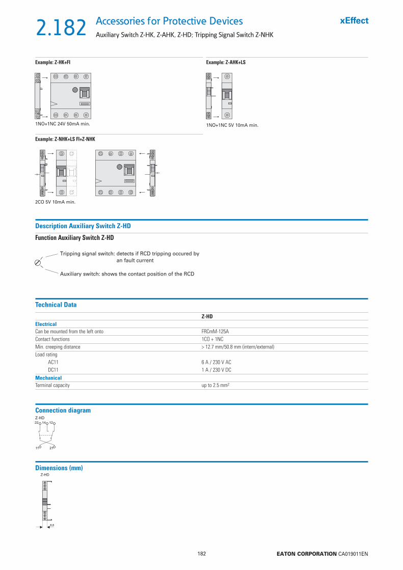
2.182
182 EATON CORPORATION CA019011EN
Accessories for Protective Devices
Auxiliary Switch Z-HK, Z-AHK, Z-HD; Tripping Signal Switch Z-NHK
Description Auxiliary Switch Z-HD
Function Auxiliary Switch Z-HD
Connection diagramZ-HD
Dimensions (mm)
Tripping signal switch: detects if RCD tripping occured by an fault current
Auxiliary switch: shows the contact position of the RCD
Technical Data
Example: Z-HK+FI
1NO+1NC 24V 50mA min.
Example: Z-AHK+LS
1NO+1NC 5V 10mA min.
Example: Z-NHK+LS FI+Z-NHK
2CO 5V 10mA min.
Z-HDElectricalCan be mounted from the left onto FRCmM-125AContact functions 1CO + 1NCMin. creeping distance > 12.7 mm/50.8 mm (intern/external)Load rating
AC11 6 A / 230 V ACDC11 1 A / 230 V DC
MechanicalTerminal capacity up to 2.5 mm2

2.183
183 EATON CORPORATION CA019011EN
Accessories for Protective DevicesAuxiliary Switch ZP-IHK, ZP-WHK; Tripping Signal Switch ZP-NHK
Design: for snappingSG60811 MCB, RCBO / 1NO+1NC ZP-IHK 286052 4/120
For Protective Device / Function Type Article No. Units perDesignation package
SG34612 MCB, RCBO / 1CO ZP-WHK 286053 4/120
SG34512 MCB, RCBO / 2CO ZP-NHK 248437 4/120
Description Auxiliary Switch ZP-IHK, ZP-WHK; Tripping Signal Switch ZP-NHK
• Design according to IEC/EN 62019• No screws required. Can be snapped onto FAZ and FRBmM-1N subsequently
• ZP-IHK, ZP-WHK: Can be snapped on additionally 1 time onto itself• The specifi ed minimum voltages are per contact. Take into account particularly in case of series connection!• Contact material and design particularly suitable for extra low voltage.• Contact function with relative movement (self-cleaning contacts)e)
• ZP-NHK: The function of one of the two change-over contacts can be switched from “auxiliary switch” to „tripping signal switch“• Tripping signal contact transmits message of electric tripping, not mechanical switch-off
• ZP-NHK: The “Service button” is used to check whether or not the auxiliary switch is correctly wired in the tripping-signal-switch position. Activating the “service button” will mechanically simulate an electrical switch-off, so the mechanism for the electrical switchoff will disengage and can be checked. The main switchgear (MCB or combined MCB/RCD) connected to the ZP-NHK auxiliary switch does not need to trip as well during an inspection through the service button.

2.184
184 EATON CORPORATION CA019011EN
Accessories for Protective Devices
Auxiliary Switch ZP-IHK, ZP-WHK; Tripping Signal Switch ZP-NHK
Technical DataZP-IHK ZP-WHK ZP-NHK
ElectricalContact function 1NO + 1NC 1CO 2CORated voltage 250 V 250 V 250 VFrequency 50/60 Hz 50/60 Hz 50/60 HzRated current 6 A 6 A 4 ARated thermal current Ith 6 A 6 A 4 AUtilisation category AC13
Rated operational current Ie 3 A / 250 V AC 3 A / 250 V AC 3 A / 250 V ACUtilisation category AC15
Rated operational current Ie 2 A / 250 V AC 2 A / 250 V AC 2 A / 250 V ACUtilisation category DC12
Rated operational current Ie 0.5 A / 110 V DC 0.5 A / 110 V DC 0.5 A / 110 V DCRated insulation voltage UI 250 V AC 250 V AC 250 V ACMinimum operational voltage per contact Umin 5 V DC 5 V DC 5 V DCMinimum operational current Imin 10 mA DC 10 mA DC 10 mA DCRated impulse withstand voltage (1,2/50μ) Uimp 2.5 kV 2.5 kV 2.5 kVConditional short circuit current with back-up fuse 6 A or FAZ-B4-HS 1 kA 1 kA 1 kAMax. back-up fuse, overload and short circuit 6 A gL / FAZ-4/../B-HS 6 A gL / FAZ-4/../B-HS 6 A gL / FAZ-4/../B-HSMechanicalCan be mounted from the left onto MCB, RCBO MCB, RCBO MCB, RCBOAccessories ZP-ASA ZP-ASA ZP-ASATripping indicator “electrical tripping” – – blue/whiteFrame size 45 mm 45 mm 45 mmDevice height 80 mm 80 mm 80 mmDevice width 8.8 mm (0.5MU) 8.8 mm (0.5MU) 8.8 mm (0.5MU)Mounting onto switching device onto switching device onto switching deviceDegree of protection, built-in IP40 IP40 IP40Terminal protection fi nger and hand touch safe according to DGUV VS3, EN 50274Terminals Lift terminals Lift terminals Lift terminalsTerminal capacity 0.5-2.5 mm2 0.5-2.5 mm2 0.5-2.5 mm2
Terminal screws M4 (Pozidrive Z2) M4 (Pozidrive Z2) M3 (Pozidrive Z1)Fastening torque of terminal screws max. 1.2 Nm max. 1.2 Nm max. 0.8-1.0 Nm
Dimensions (mm)ZP-NHKZP-IHK, ZP-WHK
Connection diagramZP-IHK ZP-WHK ZP-NHK
Example: ZP-IHK/(ZP-WHK)+LS Example: ZP-NHK+LS

2.185
185 EATON CORPORATION CA019011EN
Accessories for Protective DevicesRCCB Tripping Module Z-.AM
SG16011 RCCB Z-FAM 248293 1/60
For Protective Device Type Article No. Units perDesignation package
Description RCCB Tripping Module Z-FAM, Z-KAM
• For remote switch-off of RCCBs, standard and electronic combined RCD/MCB devices• Remote switch-off by one or several parallel potential-free contacts, e.g. pushbutton max. rated current 3 A at 250 V, take into account maximum pushbutton voltage• Remote tripping test by means of remote testing module Z-FW• Can be mounted subsequently, to be wired according to connection diagram with the respective terminals of the RCCB• No undesired voltage rise in the consumer system during remote switch-off thanks to integrated breaker contact K1-K2
SG16211 RCBO Z-KAM 248294 1/60
Technical DataZ-FAM Z-KAM
ElectricalRated voltage 230(400) V AC 230(400) V ACFrequency 50/60 Hz 50/60 HzRated tripping current In 0.01 - 0.3 A 0.01 - 0.3 AFunction 1NO 1NOMechanicalTripping module for RCCB RCBOFrame size 45 mm 45 mmDevice height 80 mm 80 mmDevice width 8.8 mm (0.5MU) 8.8 mm (0.5MU)Degree of protection, built-in IP40 IP40Terminal protection fi nger and hand touch safe according to DGUV VS3, EN 50274Terminal capacity 1 - 2x2.5 mm2 1 - 2x2.5 mm2
Connection diagram
W1 K1
W2 K2
Z-FAM Z-KAMW1
�
W2

2.186
186 EATON CORPORATION CA019011EN
Accessories for Protective Devices
RCCB Tripping Module Z-.AM
Dimensions (mm)
8,8 8,8
Z7-FAM
8,8
4580
23Z7-KAM
44
60
5,5Z-FAM Z-KAM
Connection examples: Lay lines to the switching devices with double insulation and overload protection, e.g. 4A gL or CLS6-4..-HS
Connection diagram: RCCB-2p, RCCB feed above
Connection diagram: RCCB-4p, RCCB feed above
Connection diagram: RCBO-2p, RCBO feed below
Connection diagram: RCCB-4p, RCCB feed below
Z-FAM
Z-FAM
Z-FAM
Z-KAM

2.187
187 EATON CORPORATION CA019011EN
Accessories for Protective DevicesShunt Trip Release Z-ASA, ZP-ASA
To be glued onSG00712 12-110 Z-ASA/24 248286 1/60
110-415 Z-ASA/230 248287 1/60
Operational voltage range (V~) Type Article No. Units perDesignation package
To be snapped onSG00212 12-110 ZP-ASA/24 248438 1/60
110-415 ZP-ASA/230 248439 1/60
Description Shunt Trip Release Z-ASA, ZP-ASA
• Remote release for subsequent mounting onto PXL, PLI, PXK, FAZ, FRBmM-1N, Z-MS• Module width 1MU• Additional installation of standard auxiliary switch is possible• Position indicator red - green• Type ZP-ASA for snap-on mounting
Technical DataZ-ASA24 Z-ASA230 ZP-ASA24 ZP-ASA230
ElectricalMinimum pulse duration 15 ms 10 ms 15 ms 10 msInternal resistance 2,2 215 2,2 215 Duty cycle 100% 100% 100% 100%Tripping time < 20 ms < 20 ms < 20 ms < 20 msRated peak withstand voltage (1.2/50μs) 2.5 kV 2.5 kV 2.5 kV 2.5 kVEndurance >4000 operating cycles >4000 operating cycles >4000 operating cycles >4000 operating cyclesAC voltage rangeOperating limit 10 V 60 V 10 V 60 VOperational voltage range 12-110 V 110-415 V 12-110 V 110-415 VMaximum current consumption during switch-on 15 A 2.1 A 15 A 2.1 ACurrent fl ow time at max. current consumption 10 ms 10 ms 10 ms 10 msDC voltage rangeOperating limit 9 V 72 V 9 V 72 VOperational voltage range 10-60 V 110-220 V 10-60 V 110-220 VMaximum current consumption during switch-on 21 A 1 A 21 A 1 ACurrent fl ow time at max. current consumption 2 ms 2 ms 2 ms 2 msMechanicalFrame size 45 mm 45 mm 45 mm 45 mmDevice height 80 mm 80 mm 80 mm 80 mmDevice width 17.5 mm (1MU) 17.5 mm (1MU) 17.5 mm (1MU) 17.5 mm (1MU)Mounting bonding bonding aufschnappen aufschnappenDegree of protection, built-in IP40 IP40 IP40 IP40Terminals above/below open mouthed/lift open mouthed/lift open mouthed/lift
with guideopen mouthed/lift with guide
Terminal capacity 1-25 mm2 1-25 mm2 1-25 mm2 1-25 mm2
Fastening torque of terminal screws max. 2.4 Nm max. 2.4 Nm max. 2.4 Nm max. 2.4 Nm

2.188
188 EATON CORPORATION CA019011EN
Accessories for Protective Devices
Shunt Trip Release Z-ASA, ZP-ASA
Connection diagram
Dimensions (mm)Z-ASA ZP-ASA
Example: Z-ASA + LS
Connection Example 230 V
Example: ZP-ASA + LS
Connection Example 24 V
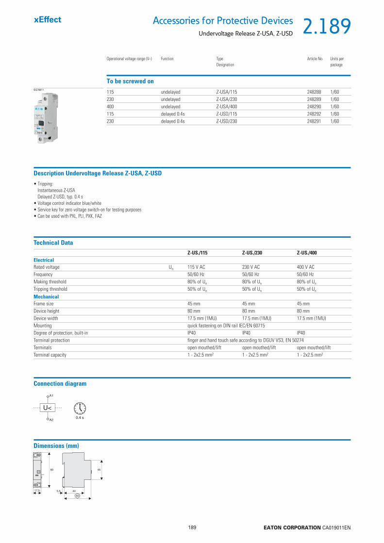
2.189
189 EATON CORPORATION CA019011EN
Accessories for Protective DevicesUndervoltage Release Z-USA, Z-USD
To be screwed onSG78811 115 undelayed Z-USA/115 248288 1/60
230 undelayed Z-USA/230 248289 1/60400 undelayed Z-USA/400 248290 1/60115 delayed 0.4s Z-USD/115 248292 1/60230 delayed 0.4s Z-USD/230 248291 1/60
Operational voltage range (V~) Function Type Article No. Units perDesignation package
Description Undervoltage Release Z-USA, Z-USD
• Tripping:Instantaneous Z-USADelayed Z-USD, typ. 0.4 s
• Voltage control indicator blue/white• Service key for zero voltage switch-on for testing purposes• Can be used with PXL, PLI, PXK, FAZ
Technical DataZ-US./115 Z-US./230 Z-US./400
ElectricalRated voltage Un 115 V AC 230 V AC 400 V ACFrequency 50/60 Hz 50/60 Hz 50/60 HzMaking threshold 80% of Un 80% of Un 80% of Un
Tripping threshold 50% of Un 50% of Un 50% of Un
MechanicalFrame size 45 mm 45 mm 45 mmDevice height 80 mm 80 mm 80 mmDevice width 17.5 mm (1MU) 17.5 mm (1MU) 17.5 mm (1MU)Mounting quick fastening on DIN rail IEC/EN 60715Degree of protection, built-in IP40 IP40 IP40Terminal protection fi nger and hand touch safe according to DGUV VS3, EN 50274Terminals open mouthed/lift open mouthed/lift open mouthed/liftTerminal capacity 1 - 2x2.5 mm2 1 - 2x2.5 mm2 1 - 2x2.5 mm2
Dimensions (mm)
Connection diagram
0.4 s
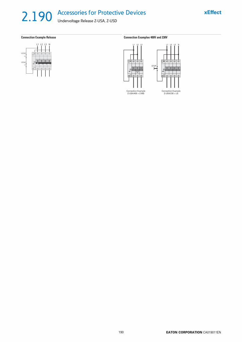
2.190
190 EATON CORPORATION CA019011EN
Accessories for Protective Devices
Undervoltage Release Z-USA, Z-USD
Connection Examplee 400V and 230VConnection Example Release
Connection ExampleZ-USA/400 + Z-MS
Connection ExampleZ-USA/230 + LS
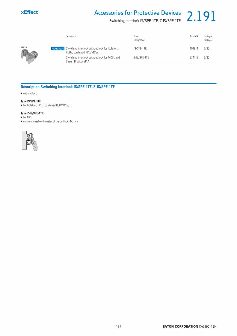
2.191
191 EATON CORPORATION CA019011EN
Accessories for Protective DevicesSwitching Interlock IS/SPE-1TE, Z-IS/SPE-1TE
SG47812 Switching interlock without lock for Isolators, RCDs, combined RCD/MCBs, ...
IS/SPE-1TE 101911 5/30
Switching interlock without lock for MCBs and Circuit Breaker ZP-A
Z-IS/SPE-1TE 274418 5/30
Description Type Article No. Units perDesignation package
PHASE OUT
Description Switching Interlock IS/SPE-1TE, Z-IS/SPE-1TE
• without lock
Type IS/SPE-1TE:• for Isolators, RCDs, combined RCD/MCBs, ...
Type Z-IS/SPE-1TE:• for MCBs• maximum usable diameter of the padlock: 4-5 mm

2.192
192 EATON CORPORATION CA019011EN
Accessories for Protective Devices
Terminal Covers
Terminal Covers for RCDsSG82011 2-poles Z-RC/AK-2TE 285385 10
4-poles Z-RC/AK-4TE 101062 10
Description Type Article No. Units perDesignation package
Terminal Covers for Add-on DeviceSG02614 2-poles Z-TC/AO-2P 178097 10
3+4-poles Z-TC/AO-3-4P 178098 10
Terminal Covers for MCB, RCBOSG02314 2-poles Z-TC/SD-2P 178099 10
3-poles Z-TC/SD-3P 178100 104-poles Z-TC/SD-4P 178101 10
Terminal Cover for MCBs 1-pole Z-TC/MCB-1P 178102 10
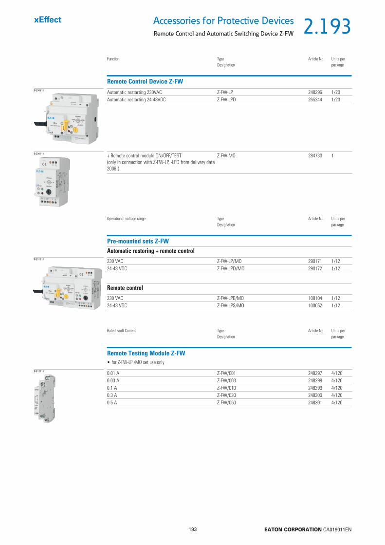
2.193
193 EATON CORPORATION CA019011EN
Accessories for Protective DevicesRemote Control and Automatic Switching Device Z-FW
SG30811 Automatic restarting 230VAC Z-FW-LP 248296 1/20Automatic restarting 24-48VDC Z-FW-LPD 265244 1/20
Function Type Article No. Units perDesignation package
SG30711 + Remote control module ON/OFF/TEST(only in connection with Z-FW-LP, -LPD from delivery date 2006!)
Z-FW-MO 284730 1
Remote Control Device Z-FW
SG31311 230 VAC Z-FW-LP/MO 290171 1/1224-48 VDC Z-FW-LPD/MO 290172 1/12
Operational voltage range Type Article No. Units perDesignation package
Pre-mounted sets Z-FWAutomatic restoring + remote control
230 VAC Z-FW-LPE/MO 108104 1/1224-48 VDC Z-FW-LPS/MO 100052 1/12
Remote control
SG12111 0.01 A Z-FW/001 248297 4/1200.03 A Z-FW/003 248298 4/1200.1 A Z-FW/010 248299 4/1200.3 A Z-FW/030 248300 4/1200.5 A Z-FW/050 248301 4/120
Rated Fault Current Type Article No. Units perDesignation package
Remote Testing Module Z-FW• for Z-FW-LP./MO set use only

2.194
194 EATON CORPORATION CA019011EN
Accessories for Protective Devices
Remote Control and Automatic Switching Device Z-FW
Description Remote Testing Module and Remote Control Device Z-FW• Shape compatible switching device suitable for subsequent installation for automatic re-setting and remote control of MCBs, RCCBs and Z-MS• Mechanical interlock, can be sealed with leads• Mechanical switching capability up to max. RCCB-100/4p, MCB-100/4p• Operating and alarm display by green and red LED• Function extension with Switching Modul Z-FW-MO
Operating and trouble display by LED pre-assembled only with Z-FW...
Technical DataZ-FW-LP Z-FW-LPD Z-FW-MO
ElectricalPossible operating voltages 220-240 V AC 24-48 V DC –Frequency 50/60 Hz – –Testing module (0.5MU) for remote testing of RCDs Z-FW... Z-FW... –Control voltage for remote control – – 24-230 V AC/DCRelay output for tripping test with Z-FW – – 400 V AC max.Relay output for alarm, potential-free 5 A / 250 V AC 5 A / 250 V AC –Functions Automatic restarting Automatic restarting +ON/OFF/TESTFunction selector Automatic 5x, OFF/RESET Automatic 5x, OFF/RESET ON, OFF/RESETRemote control function via telephone with Telecommander – – –MechanicalFrame size 45 mm 45 mm 45 mmDevice height 80 mm 80 mm 80 mmDevice width 70 mm 70 mm 35 mmMounting quick fastening with 2 lock-in positions on DIN rail IEC/EN 60715 –Degree of protection, built-in IP40 IP40 IP40Terminal protection fi nger and hand touch safe according to DGUV VS3, EN 50274Terminals Lift terminals Lift terminals Lift terminalsTerminal capacity 2 x 1.5 mm2
or 1 x 2.5 mm22 x 1.5 mm2 or 1 x 2.5 mm2
4 x 1,5 mm2 or 2 x 2.5 mm2
Scope of delivery – – Coupling plug
Dimensions (mm)Z-FW-LP, -LPD, -LPE, -LPS Z-FW-MO
Connection diagramZ-FW-LP Z-FW-LPD Z-FW-MO
Connection Example
FI Z-FW-LP
Z-FW-MO
Power supplyAC/DC 24-230 VElectrical system
LS-HS
FI
Z-FW-LPD
LS-HS
24-48 V DC

2.195
195 EATON CORPORATION CA019011EN
Accessories for Protective DevicesRemote Control and Automatic Switching Device Z-FW
Description Remote Testing Module Z-FW (for Z-FW-LP)
• External testing module with testing resistor for RCDs• Proper „external“ test key function according to the applicable rules thanks to design adapted to the rated tripping current• For remote testing with remote control and automatic switching device Z-FW-LP• No undesired voltage rise in the consumer system during remote switch-off thanks to integrated breaker contact K1-K2• Can also be used as a remote tripping module for RCDs
Technical DataZ-FW-LP/MO Z-FW-LPD/MO Z-FW-LPE/MO Z-FW-LPS/MO
ElectricalPossible operating voltages 220-240 V AC 24-48 V DC 220-240 V AC 24-48 V DCFrequency 50/60 Hz – 50/60 Hz –Testing module (0.5MU) for remote testing of RCDs Z-FW... Z-FW... Z-FW... Z-FW...Control voltage for remote control 24-230 V AC/DC 24-230 V AC/DC 24-230 V AC/DC 24-230 V AC/DCRelay output for tripping test with Z-FW 400 V AC max. 400 V AC max. 400 V AC max. 400 V AC max.Relay output for alarm, potential-free 5 A / 250 V AC 5 A / 250 V AC 5 A / 250 V AC 5 A / 250 V ACFunctions Automatic restoring
+ remote controlAutomatic restoring + remote control
Remote control Remote control
MechanicalFrame size 45 mm 45 mm 45 mm 45 mmDevice height 80 mm 80 mm 80 mm 80 mmDevice width 105 mm 105 mm 105 mm 105 mmMounting quick fastening with 2 lock-in positions on DIN rail IEC/EN 60715Degree of protection, built-in IP40 IP40 IP40 IP40Terminal protection fi nger and hand touch safe according to DGUV VS3, EN 50274Terminals Lift terminals Lift terminals Lift terminals Lift terminals
Dimensions (mm)
Connection Examplee
Connection diagram: RCCB-4p, RCD feed above
Z-FW
RCCB-4p Z-FW-LP
Connection diagram: RCCB-2p, RCD feed above
Z-FW RCCB-2p
Z-FW-LP
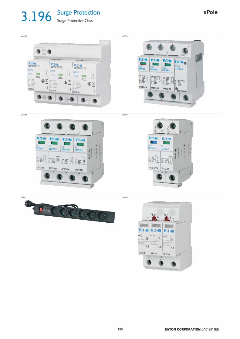
3.196
196 EATON CORPORATION CA019011EN
Surge Protection
Surge Protective Class
sg04518_r sg03316
sg04813 sg03316
N04011 sg04914

3.197
197 EATON CORPORATION CA019011EN
Surge ProtectionSurge Protective Class T1/T2, SPRT12-350
Poles Max. Continous Operating VoltageUC
TypeDesignation
Article No. Units perpackage
Combined Surge Protective Device SPRT12-350
3pole 350 VAC SPRT12-350/3-AX 195235 1
• incl. FM contact (change-over contact)• for TN-C
3pole+NPE 350 VAC SPRT12-350/3+NPE-AX 195236 1
Range of protection Max. Continous Operating VoltageUC
TypeDesignation
Article No. Units perpackage
Insert for SPRT12-350
L-N / L-PEN 350 VAC SPRT12-350 195237 1N-PE 350 VAC SPRT12-350/NPE 195238 1
sg04518_r
sg04418_r
sg04318_r
• incl. FM contact (change-over contact)• for TN-S/TT

3.198
198 EATON CORPORATION CA019011EN
Surge Protection
Surge Protective Class T1/T2, SPRT12-350
Description Surge Protective Class T1/T2
• Ready-to-connect Combined Surge Protection Device Type 1/2 on the basis of spark gaps• Consisting of the base unit and plug-type modules
Technical DataSPRT12-350/3-AX SPRT12-350/3+NPE-AX
General dataStandards/regulations IEC 61643-11, EN 61643-11 IEC 61643-11, EN 61643-11IEC test classifi cation T1 / T2 T1 / T2
EN type T1 / T2 T1 / T2Number of ports One OneSPD design Voltage-switching type Voltage-switching typeMode of protection L-PEN L-N, L-PE, N-PEMounting type DIN rail 35 mm DIN rail 35 mmSurge protection fault message Optical, remote indicator contact Optical, remote indicator contactColor Light grey RAL 7035 Light grey RAL 7035Insulating material PBT-FR PBT-FRHousing material PBT-FR PBT-FRAir clearances and creepage distances (according to EN 60664-1 and EN 61643-11)
Degree of pollution 2 2Overvoltage category III IIIMaterial group I ICTI value of material 600 600Umax < 2 kV < 2 kV
Flammability rating according to UL 94 V-0 V-0Degree of protection IP20 (only when all terminal points are used) IP20 (only when all terminal points are used)Shock (operation) 30 g (Half-sine / 11 ms / 3x ±X, ±Y, ±Z) 30 g (Half-sine / 11 ms / 3x ±X, ±Y, ±Z)Vibration (operation) 5 g (5 - 500 Hz/2.5 h/X, Y, Z) 5 g (5 - 500 Hz/2.5 h/X, Y, Z)Ambient temperature (operation) -40 °C ... 80 °C -40 °C ... 80 °CAmbient temperature (storage/transport) -40 °C ... 80 °C -40 °C ... 80 °CPermissible humidity (operation) 5 % ... 95 % 5 % ... 95 %Altitude 2000 m (amsl (above mean sea level)) 2000 m (amsl (above mean sea level))Width 106.8 mm 142.4 mmHeight 97 mm 95 mmDepth 71.2 mm (incl. DIN rail 7.5 mm) 71.2 mm (incl. DIN rail 7.5 mm)Horizontal pitch 6 Module units 8 Module unitsElectrical dataNominal voltage UN
240/415 V AC (TN-C) 240/415 V AC (TN-S)240/415 V AC (TT)
Nominal frequency fN 50 Hz (60 Hz) 50 Hz (60 Hz)Maximum continuous operating voltage UC 350 V AC 350 V ACReference test voltage UREF 264 V AC 264 V ACRated load current IL 125 A (< 55 °C) 125 A (< 55 °C)Nominal discharge current (8/20) μs In
(L-PEN) 25 kA -(L-N) - 25 kA(L-PE) - 25 kA(N-PE) - 100 kA
Maximum discharge current (8/20) μs Imax
(L-PEN) 50 kA -(L-N) - 50 kA(L-PE) - 50 kA
Impulse discharge current (10/350) μsPeak value Iimp 25 kA (L-PEN) 25 kA (L-N)Charge 12.5 As (L-PEN) 12.5 As (L-N)Specifi c energy 160 kJ/ (L-PEN) 160 kJ/ (L-N)
Impulse discharge current (10/350) μs (L-PE)Peak value Iimp - 25 kACharge - 12.5 AsSpecifi c energy - 160 kJ/

3.199
199 EATON CORPORATION CA019011EN
Surge ProtectionSurge Protective Class T1/T2, SPRT12-350
SPRT12-350/3-AX SPRT12-350/3+NPE-AXImpulse discharge current (10/350) μs (N-PE)
Peak value Iimp - 100 kACharge - 50 AsSpecifi c energy - 2500 kJ/
Total discharge current (10/350) μs Itotal 75 kA 100 kAFollow current interrupt rating Ifi
(L-PEN) 50 kA -(L-N) - 50 kA(N-PE) - 100 A
Short-circuit current rating ISCCR 50 kA 50 kAVoltage protection level Up
(L-PEN) 1.5 kV -(L-N) - 1.5 kV(L-PE) - 2.5 kV(N-PE) - 1.5 kV
Residual voltage Ures
(L-PEN) 1.5 kV (at In) -(L-N) - 1.5 kV (at In)(L-PE) - 2.5 kV (at In)(N-PE) - 1.5 kV (at In)
Front of wave sparkover voltage at 6 kV (1.2/50) μs(L-PEN) 1.5 kV -(L-N) - 1.5 kV(L-PE) - 2.5 kV(N-PE) - 1.5 kV
TOV behavior at UT
(L-PEN) 415 V AC (5 s / withstand mode) -457 V AC (120 min / withstand mode) -
(L-N) - 415 V AC (5 s / withstand mode)457 V AC (120 min / withstand mode)
(N-PE) - 1200 V AC (200 ms / withstand mode)Response time tA 100 ns 100 nsCurrent tripping factor k 1.6 1.6Max. backup fuse with branch wiring 315 A (gG) 315 A (gG)Max. backup fuse with V-type through wiring (at 35 mm2) 125 A (gG) 125 A (gG)Additional technical dataFollow current interrupt rating Ifi 100 kA (264 V AC) 100 kA (264 V AC) (L-N)Short-circuit current rating ISCCR 100 kA (264 V AC) 100 kA (264 V AC)Remote signalingConnection name Remote fault indicator contact Remote fault indicator contactSwitching function PDT contact PDT contactConnection method Plug-in/screw connection via COMBICON Plug-in/screw connection via COMBICONOperating voltage 12 V AC ... 250 V AC 12 V AC ... 250 V AC
125 V DC (200 mA DC) 125 V DC (200 mA DC)Operating current 10 mA AC ... 1 A AC 10 mA AC ... 1 A AC
1 A DC (30 V DC) 1 A DC (30 V DC)Screw thread M2 M2Conductor cross section
fl exible 0.14 mm2 ... 1.5 mm2 0.14 mm2 ... 1.5 mm2
solid 0.14 mm2 ... 1.5 mm2 0.14 mm2 ... 1.5 mm2
AWG 28 ... 16 28 ... 16Stripping length 7 mm 7 mmTightening torque 0.25 Nm 0.25 NmConnection dataConnection method Screw terminal blocks Screw terminal blocksScrew thread M5 M5Connection technology Biconnect terminal block Biconnect terminal blockConductor cross section
fl exible, solid 2.5 mm2 ... 35 mm2 2.5 mm2 ... 35 mm2
AWG 13 ... 2 13 ... 2Stripping length 18 mm 18 mmConnection method Fork-type cable lug Fork-type cable lugDiameter 5 mm 5 mmConductor cross section fl exible 1.5 mm2 ... 16 mm2 1.5 mm2 ... 16 mm2
Tightening torque 4.5 Nm 4.5 Nm

3.200
200 EATON CORPORATION CA019011EN
Surge Protection
Surge Protective Class T1/T2, SPRT12-350
Circuit diagrams
PEN
L1 L3L2
12 14
11 FM
Dimensions (mm)
106,8
71,2
51,5
63,7
97
90
45
22,5
SPRT12-350/3-AX
SPRT12-350/3-AX
12 14
11 FM
N
PE L2L1 L3
SPRT12-350/3+NPE-AX
71,2
51,5
95
90
45
22,5
63,7
142,4
SPRT12-350/3+NPE-AX
SPRT12-350, SPRT12-350/NPE
56,1
4935,5
44,8
SPRT12-350, SPRT12-350/NPE
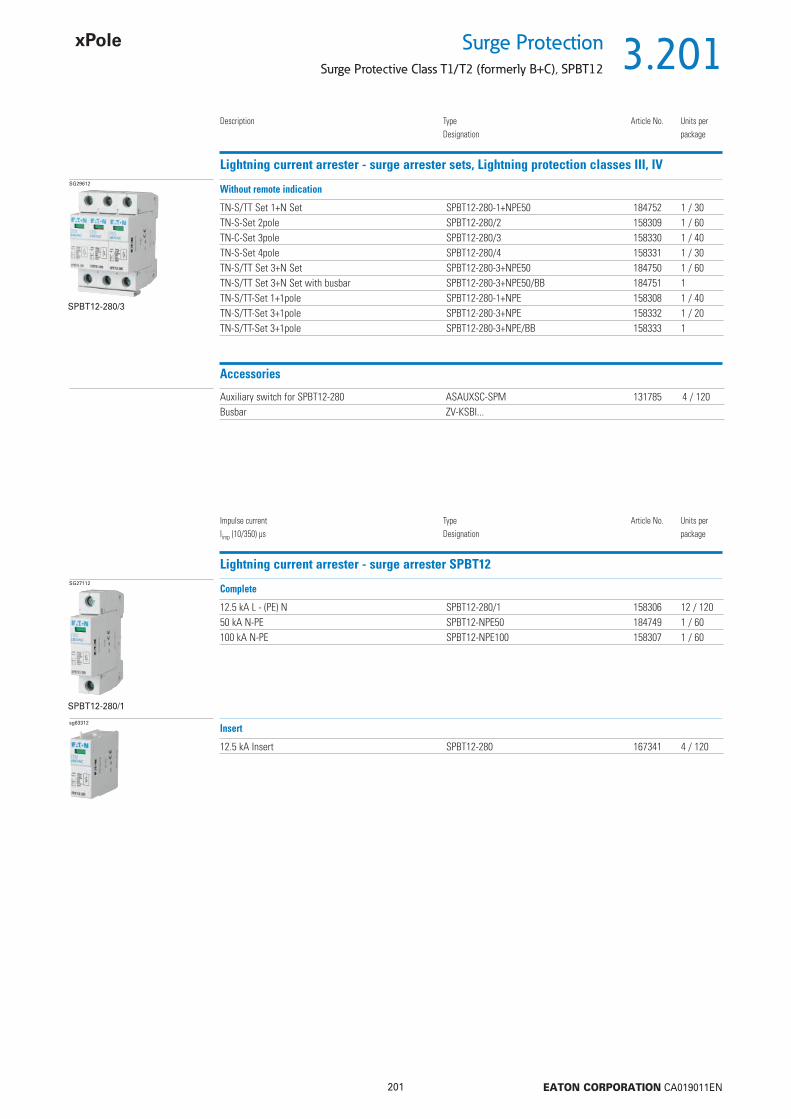
3.201
201 EATON CORPORATION CA019011EN
Surge ProtectionSurge Protective Class T1/T2 (formerly B+C), SPBT12
Description TypeDesignation
Article No. Units perpackage
Lightning current arrester - surge arrester sets, Lightning protection classes III, IVSG29612
SPBT12-280/3
TN-S/TT Set 1+N Set SPBT12-280-1+NPE50 184752 1 / 30TN-S-Set 2pole SPBT12-280/2 158309 1 / 60TN-C-Set 3pole SPBT12-280/3 158330 1 / 40TN-S-Set 4pole SPBT12-280/4 158331 1 / 30TN-S/TT Set 3+N Set SPBT12-280-3+NPE50 184750 1 / 60TN-S/TT Set 3+N Set with busbar SPBT12-280-3+NPE50/BB 184751 1TN-S/TT-Set 1+1pole SPBT12-280-1+NPE 158308 1 / 40TN-S/TT-Set 3+1pole SPBT12-280-3+NPE 158332 1 / 20TN-S/TT-Set 3+1pole SPBT12-280-3+NPE/BB 158333 1
Without remote indication
Accessories Auxiliary switch for SPBT12-280 ASAUXSC-SPM 131785 4 / 120
Busbar ZV-KSBI...
Impulse current Iimp (10/350) μs
TypeDesignation
Article No. Units perpackage
Lightning current arrester - surge arrester SPBT12SG27112
SPBT12-280/1
12.5 kA L - (PE) N SPBT12-280/1 158306 12 / 12050 kA N-PE SPBT12-NPE50 184749 1 / 60100 kA N-PE SPBT12-NPE100 158307 1 / 60
Complete
sg63312
12.5 kA Insert SPBT12-280 167341 4 / 120
Insert

3.202
202 EATON CORPORATION CA019011EN
Surge Protection
Surge Protective Class T1/T2 (formerly B+C), SPBT12
Description Surge Protective Class T1&T2
• Field of application: For the protection of low voltage distribution systems against transient overvoltage caused by direct and indirect lightning stroke and switching operations• Application according to IEC 60364-5-53 Clause 534• Test class I , II according to IEC 61643-1• SPD-type T1 , T2 according to EN 61643-11• Lightning protection classes III and IV according to IEC 62305• Busbars ZV-KSBI are available for all customary applications
Technical DataSPBT12-280... SPBT12-NPE50 SPBT12-NPE100
Electrical per poleResponding time (rate of voltage rise 5 kV/μs) < 25 ns < 100 ns < 100 nsVoltage protection level Up < 1.5 kV < 1.4 kV < 1.5 kVVoltage protection level at 5 kA (8/20) μs Up 950 V – –Max. continuous operating voltage UC 280 VAC 260 VAC 255 VACTOV test value UT 370 VAC (5 s) 1200 VAC (200 ms) 1200 VAC (200 ms)Rated frequency 50/60 Hz 50/60 Hz 50/60 HzOpen circuit voltage Uoc 10 kV – 20 kVNominal discharge current (8/20) μs In 25 kA 50 kA 100 kAMax. discharge current Imax 50 kA 100 kA 100 kAImpulse current (10/350) μs Iimp
Peak current 12.5 kA 50 kA 100 kACharge Q 6.25 As 25 As 50 AsSpecifi c energy 39,1 kJ/ 625 kJ/ 2500 kJ/
Follow current interrupt rating Ifi – 100 Ar.m.s. 100 Ar.m.s.
Maximum back-up fuse 160 AgL/gG – –Maximum short-circuit current 50 Ar.m.s. – –Connection diagram
MechanicalFrame size 45 mm 45 mm 45 mmDevice height 80 mm 80 mm 80 mmDevice width 17.5 mm 17.5 mm 35 mmWeight 121 g 93 g 250 gPermitted ambient temperature -40°C to +70°C -40°C to +70°C -40°C to +70°CDegree of protection (built-in) IP40 IP40 IP40Upper and lower lift terminal capacity 4 - 25 mm2 top 4 - 50 mm2. bottom 4 - 35 mm2 4 - 35 mm2
Upper and lower open mouthed terminals for busbar thickness up to 1.5 mm top - / bottom 1.5 mm 1.5 mmTightening torque of terminal screws 2.4 - 3 Nm 2.4 - 3 Nm 2.4 - 3 NmQuick fastening on DIN rail according to IEC/EN 60715 IEC/EN 60715 IEC/EN 60715Accessories: busbars 16 mm2 Type ZV-KSBI ... Type ZV-KSBI ... Type ZV-KSBI ...
Dimensions (mm) Lightning current arrester - surge arrester sets, Lightning protection classes III, IV
. . . SPBT12-280
SPBT12-280 SPBT12-NPE100SPBT12-NPE50
SPBT12-280/2 SPBT12-280/3

3.203
203 EATON CORPORATION CA019011EN
Surge ProtectionSurge Protective Class T1/T2 (formerly B+C), SPBT12
Technical DataSPBT12-280-1+NPE50 SPBT12-280-3+NPE50
Electrical per poleResponding time (rate of voltage rise 5 kV/μs) L-N / N-PE < 25 ns / < 100 ns < 25 ns / < 100 nsVoltage protection level L-N / L-PE / N-PE Up < 1.5 kV < 1.5 kVMax. continuous operating voltage L-N / N-PE UC 280 VAC / 260 VAC 280 VAC / 260 VACTOV test value UT
5 s L-N / L-PE 348 VAC / 370 VAC 348 VAC / 370 VAC200 ms N-PE 1200 VAC 1200 VAC
Rated frequency 50/60 Hz 50/60 HzOpen circuit voltage Uoc 10 kV 20 kVNominal discharge current (8/20) μs L-N / N-PE In 25 kA / 50 kA 3x25 kA / 50 kAMax. discharge current L-N / N-PE Imax 50 kA / 100 kA 3x50 kA / 100 kAImpulse current (10/350) μs Iimp
Peak current L-N / N-PE 12.5 kA / 50 kA 3x12.5 kA / 50 kACharge Q 25 As 25 AsSpecifi c energy 625 kJ/ 625 kJ/
Follow current interrupt rating N-PE Ifi 100 Ar.m.s. 100 Ar.m.s.
Maximum back-up fuse – –Maximum short-circuit current – –Connection diagram L
N
PE L1
N
PE L2 L3
MechanicalFrame size 45 mm 45 mmDevice height 80 mm 80 mmDevice width 35 mm 70 mmWeight 218 g 470 gPermitted ambient temperature -40°C to +70°C -40°C to +70°CDegree of protection (built-in) IP40 IP40Upper and lower lift terminal capacity
L, N 4 - 25 mm2 4 - 25 mm2
N, PE 4 - 50 mm2 4 - 50 mm2
Upper and lower open mouthed terminals for busbar thickness up to 1.5 mm 1.5 mmTightening torque of terminal screws 2.4 - 3 Nm 2.4 - 3 NmQuick fastening on DIN rail according to IEC/EN 60715 IEC/EN 60715Accessories: busbars 16 mm2 Type ZV-KSBI ... Type ZV-KSBI ...
Lightning current arrester - surge arrester sets, Lightning protection classes III, IV
. . . SPBT12-280
. . . SPBT12-NPE50
. . . ASLTT-63
TN-S-System
3 x 230/400 VAC
(3 x 220/380 VAC)
(3 x 240/415 VAC)
N
PEL
L1, L2, L3, N, PEL, N, PE
TN-S/TT-System3 x 230/400 VAC
(3 x 220/380 VAC)
(3 x 240/415 VAC)
TN-S/TT-System3 x 230/400 VAC
(3 x 220/380 VAC)
(3 x 240/415 VAC)
L1 L2 L3L1 L2 L3 N
2 1 1 1 1 31 1 1
N
PE
2
N
PE
2
SPBT12-280-1+NPE50 SPBT12-280-3+NPE50 SPBT12-280-3+NPE50/BB
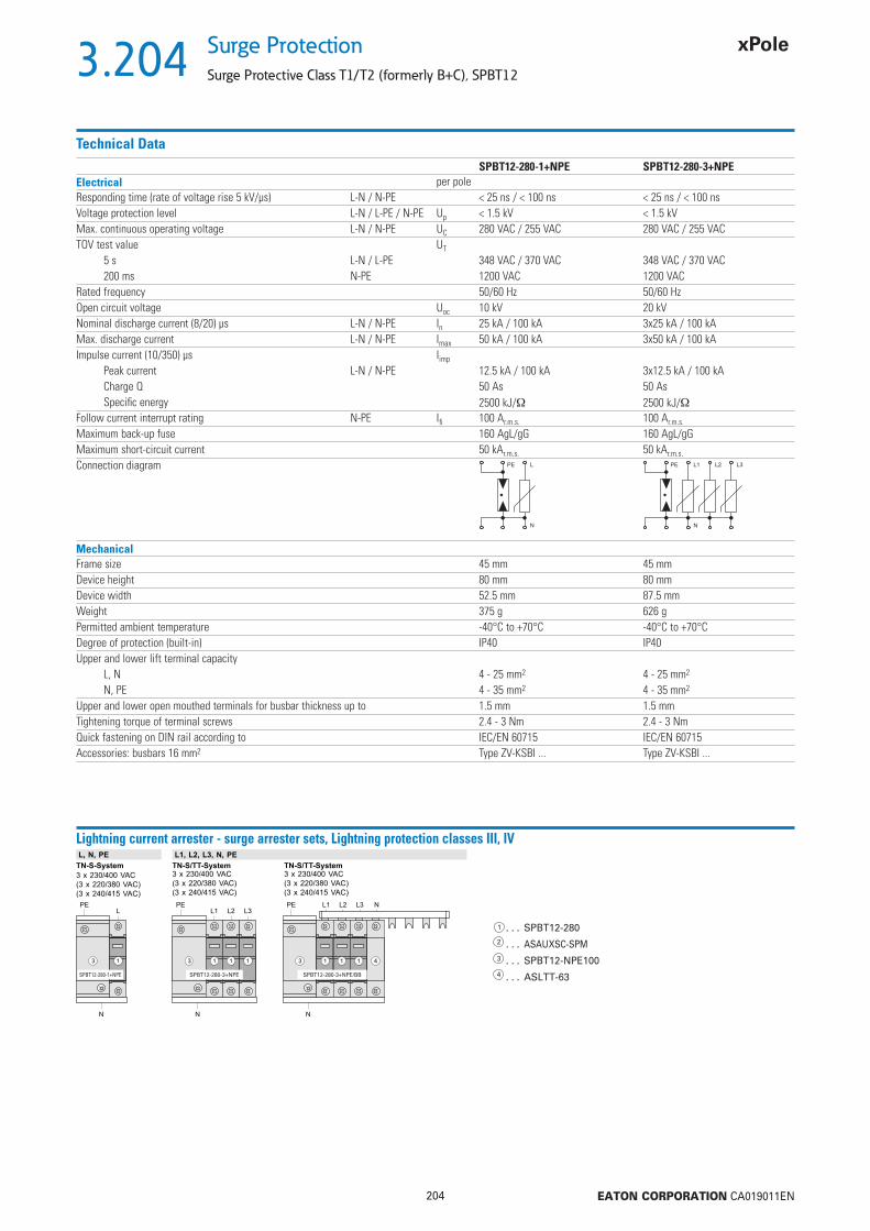
3.204
204 EATON CORPORATION CA019011EN
Surge Protection
Surge Protective Class T1/T2 (formerly B+C), SPBT12
Technical DataSPBT12-280-1+NPE SPBT12-280-3+NPE
Electrical per poleResponding time (rate of voltage rise 5 kV/μs) L-N / N-PE < 25 ns / < 100 ns < 25 ns / < 100 nsVoltage protection level L-N / L-PE / N-PE Up < 1.5 kV < 1.5 kVMax. continuous operating voltage L-N / N-PE UC 280 VAC / 255 VAC 280 VAC / 255 VACTOV test value UT
5 s L-N / L-PE 348 VAC / 370 VAC 348 VAC / 370 VAC200 ms N-PE 1200 VAC 1200 VAC
Rated frequency 50/60 Hz 50/60 HzOpen circuit voltage Uoc 10 kV 20 kVNominal discharge current (8/20) μs L-N / N-PE In 25 kA / 100 kA 3x25 kA / 100 kAMax. discharge current L-N / N-PE Imax 50 kA / 100 kA 3x50 kA / 100 kAImpulse current (10/350) μs Iimp
Peak current L-N / N-PE 12.5 kA / 100 kA 3x12.5 kA / 100 kACharge Q 50 As 50 AsSpecifi c energy 2500 kJ/ 2500 kJ/
Follow current interrupt rating N-PE Ifi 100 Ar.m.s. 100 Ar.m.s.
Maximum back-up fuse 160 AgL/gG 160 AgL/gG Maximum short-circuit current 50 kAr.m.s. 50 kAr.m.s.
Connection diagram L
N
PE L1
N
PE L2 L3
MechanicalFrame size 45 mm 45 mmDevice height 80 mm 80 mmDevice width 52.5 mm 87.5 mmWeight 375 g 626 gPermitted ambient temperature -40°C to +70°C -40°C to +70°CDegree of protection (built-in) IP40 IP40Upper and lower lift terminal capacity
L, N 4 - 25 mm2 4 - 25 mm2
N, PE 4 - 35 mm2 4 - 35 mm2
Upper and lower open mouthed terminals for busbar thickness up to 1.5 mm 1.5 mmTightening torque of terminal screws 2.4 - 3 Nm 2.4 - 3 NmQuick fastening on DIN rail according to IEC/EN 60715 IEC/EN 60715Accessories: busbars 16 mm2 Type ZV-KSBI ... Type ZV-KSBI ...
Lightning current arrester - surge arrester sets, Lightning protection classes III, IV
. . . SPBT12-280
. . . ASAUXSC-SPM
. . . SPBT12-NPE100
. . . ASLTT-63
TN-S-System
3 x 230/400 VAC
(3 x 220/380 VAC)
(3 x 240/415 VAC)
N
PEL
L1, L2, L3, N, PEL, N, PE
TN-S/TT-System3 x 230/400 VAC
(3 x 220/380 VAC)
(3 x 240/415 VAC)
TN-S/TT-System3 x 230/400 VAC
(3 x 220/380 VAC)
(3 x 240/415 VAC)
L1 L2 L3
N
PE L1 L2 L3
N
PE N
3 3 31 1 1 1 41 1 1
SPBT12-280-1+NPE SPBT12-280-3+NPE SPBT12-280-3+NPE/BB

3.205
205 EATON CORPORATION CA019011EN
Surge ProtectionSurge Protective Class T2 (formerly C), SPCT2
Poles Max. Continous Operating Voltage UC
In (8/20) μs TypeDesignation
Article No. Units perpackage
1pole 75 VAC 20 kA SPCT2-075/1 167578 12/1201pole 135 VAC 20 kA SPCT2-135/1 167583 12/1201pole 175 VAC 20 kA SPCT2-175/1 167588 12/1201pole 280 VAC 20 kA SPCT2-280/1 167593 12/1201pole 335 VAC 20 kA SPCT2-335/1 167598 12/1201pole 385 VAC 20 kA SPCT2-385/1 167603 12/1201pole 460 VAC 20 kA SPCT2-460/1 167608 12/1201pole 580 VAC 20 kA SPCT2-580/1 167613 12/1201pole 260 VAC 30 kA SPCT2-NPE60/1 167618 12/1202pole 75 VAC 2x20 kA SPCT2-075/2 167579 1/602pole 135 VAC 2x20 kA SPCT2-135/2 167584 1/602pole 175 VAC 2x20 kA SPCT2-175/2 167589 1/602pole 280 VAC 2x20 kA SPCT2-280/2 167594 1/602pole 335 VAC 2x20 kA SPCT2-335/2 167599 1/602pole 385 VAC 2x20 kA SPCT2-385/2 167604 1/602pole 460 VAC 2x20 kA SPCT2-460/2 167609 1/602pole 580 VAC 2x20 kA SPCT2-580/2 167614 1/603pole 75 VAC 3x20 kA SPCT2-075/3 167580 1/403pole 135 VAC 3x20 kA SPCT2-135/3 167585 1/403pole 175 VAC 3x20 kA SPCT2-175/3 167590 1/403pole 280 VAC 3x20 kA SPCT2-280/3 167595 1/403pole 335 VAC 3x20 kA SPCT2-335/3 167600 1/403pole 385 VAC 3x20 kA SPCT2-385/3 167605 1/403pole 460 VAC 3x20 kA SPCT2-460/3 167610 1/403pole 580 VAC 3x20 kA SPCT2-580/3 167615 1/404pole 75 VAC 4x20 kA SPCT2-075/4 167581 1/304pole 135 VAC 4x20 kA SPCT2-135/4 167586 1/304pole 175 VAC 4x20 kA SPCT2-175/4 167591 1/304pole 280 VAC 4x20 kA SPCT2-280/4 167596 1/304pole 335 VAC 4x20 kA SPCT2-335/4 167601 1/304pole 385 VAC 4x20 kA SPCT2-385/4 167606 1/304pole 460 VAC 4x20 kA SPCT2-460/4 167611 1/304pole 580 VAC 4x20 kA SPCT2-580/4 167616 1/301+N 280 VAC 20 kA SPCT2-280-1+NPE 167619 1/601+N 335 VAC 20 kA SPCT2-335-1+NPE 167621 1/601+N 385 VAC 20 kA SPCT2-385-1+NPE 167623 1/601+N 460 VAC 20 kA SPCT2-460-1+NPE 167625 1/601+N 580 VAC 20 kA SPCT2-580-1+NPE 167627 1/603+N 280 VAC 20 kA SPCT2-280-3+NPE 167620 1/303+N 335 VAC 20 kA SPCT2-335-3+NPE 167622 1/303+N 385 VAC 20 kA SPCT2-385-3+NPE 167624 1/303+N 460 VAC 20 kA SPCT2-460-3+NPE 167626 1/303+N 580 VAC 20 kA SPCT2-580-3+NPE 167628 1/303+N/BB 280 VAC 3x20 kA SPCT2-280-3+NPE/BB 167629 13+N/BB 335 VAC 3x20 kA SPCT2-335-3+NPE/BB 167630 13+N/BB 385 VAC 3x20 kA SPCT2-385-3+NPE/BB 167631 13+N/BB 460 VAC 3x20 kA SPCT2-460-3+NPE/BB 167632 1
Plug-in surge arrester SPCT2. 1- to 4poleSG04713
SPCT2-280/3
Complete (2- and multi-pole surge arresters are supplied with busbar)
Insert 75 VAC 20 kA SPCT2-075 167577 4/120Insert 135 VAC 20 kA SPCT2-135 167582 4/120Insert 175 VAC 20 kA SPCT2-175 167587 4/120Insert 280 VAC 20 kA SPCT2-280 167592 4/120Insert 335 VAC 20 kA SPCT2-335 167597 4/120Insert 385 VAC 20 kA SPCT2-385 167602 4/120Insert 460 VAC 20 kA SPCT2-460 167607 4/120Insert 580 VAC 20 kA SPCT2-580 167612 4/120Insert 260 VAC 30 kA SPCT2-NPE60 167617 4/120
Plug-in surge arrester SPCT2. Insertsg08213
Insert 1pole

3.206
206 EATON CORPORATION CA019011EN
Surge Protection
Surge Protective Class T2 (formerly C), SPCT2
Description Surge Protective Class T2
• Field of application: For the protection of low voltage distribution systems against transient overvoltage caused by direct and indirect lightning stroke and switching operations• Test class II according to IEC 61643-1+A1• SPD-type T2 , according to EN 61643-11• Auxiliary switch ASAUXSC-SPM for remote message transmission can be mounted onto the device
Technical DataInserts SPCT2-075 SPCT2-135 SPCT2-175 SPCT2-280 SPCT2-335 SPCT2-385 SPCT2-460ElectricalMechanical coding x x x x x x xResponding time (rate of voltage rise 5 kV/μs) < 25 ns < 25 ns < 25 ns < 25 ns < 25 ns < 25 ns < 25 nsVoltage protection level at nominal discharge current / Uoc Up < 550 V < 800 V < 1.0 kV < 1.4 kV < 1.6 kV < 1.8 kV < 2.2 kVVoltage protection level at 5 kA (8/20) μs Up 400 V 550 V 700 V 1000 V 1200 V 1350 V 1700 VMax. continuous operating voltage UC 75 VAC 135 VAC 175 VAC 280 VAC 335 VAC 385 VAC 460 VACTOV test value (5 s) UT = UC = UC = UC 350 VAC 415 VAC 415 VAC 580 VACRated frequency 50/60 Hz 50/60 Hz 50/60 Hz 50/60 Hz 50/60 Hz 50/60 Hz 50/60 HzOpen circuit voltage Uoc – – – 10 kV 5 kV – –Nominal discharge current (8/20) μs In 15 kA 20 kA 20 kA 20 kA 20 kA 20 kA 20 kACharge Q at In 0.43 As 0.57 As 0.57 As 0.57 As 0.57 As 0.57 As 0.57 AsSpecifi c energy at In 3.2 kJ/ 5.7 kJ/ 5.7 kJ/ 5.7 kJ/ 5.7 kJ/ 5.7 kJ/ 5.7 kJ/Max. discharge current Imax 30 kA 40 kA 40 kA 40 kA 40 kA 40 kA 40 kAFollow current interrupt rating Ifi – – – – – – –Maximum back-up fuseMaximum short-circuit current 125 AgL
50 kAr.m.s.
PLHT-C100 20 kAr.m.s.
Connection diagram
MechanicalFrame size 45 mmDevice height 80 mmDevice width
1pole 17.5 mm (1MU)1+1pole, 2pole 35 mm (2MU)3pole 52.5 mm (3TE)3+1pole, 4pole 70 mm (4TE)
Mechanical coding1pole x1+1pole yx2pole xx3pole xxx3+1pole yxxx4pole xxxx
Weight base 1P, 1+1P, 2P, 3P, 3+1P, 4P 53/120/120/180/240/240 gWeight complete devices 1P, 1+1P, 2P, 3P, 3+1P, 4P 110/201/220/330/412/440 gPermitted ambient temperature -40°C to +70°CDegree of protection (built-in) IP40Upper and lower lift terminal capacity 4 - 25 mm2
Upper and lower open mouthed terminals for busbar thickness up to 1.5 mmTightening torque of terminal screws 2.4 - 3 NmQuick fastening on DIN rail according to IEC/EN 60715Accessories: busbars 16 mm2 Type ZV-KSBI ...
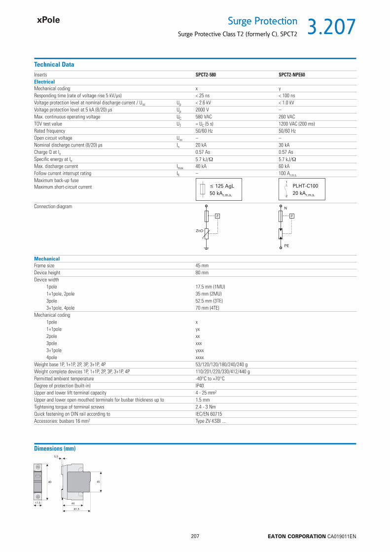
3.207
207 EATON CORPORATION CA019011EN
Surge ProtectionSurge Protective Class T2 (formerly C), SPCT2
Technical DataInserts SPCT2-580 SPCT2-NPE60ElectricalMechanical coding x yResponding time (rate of voltage rise 5 kV/μs) < 25 ns < 100 nsVoltage protection level at nominal discharge current / Uoc Up < 2.6 kV < 1.0 kVVoltage protection level at 5 kA (8/20) μs Up 2000 V –Max. continuous operating voltage UC 580 VAC 260 VACTOV test value UT = UC (5 s) 1200 VAC (200 ms)Rated frequency 50/60 Hz 50/60 HzOpen circuit voltage Uoc – –Nominal discharge current (8/20) μs In 20 kA 30 kACharge Q at In 0.57 As 0.57 AsSpecifi c energy at In 5.7 kJ/ 5.7 kJ/Max. discharge current Imax 40 kA 60 kAFollow current interrupt rating Ifi – 100 Ar.m.s.
Maximum back-up fuseMaximum short-circuit current 125 AgL
50 kAr.m.s.
PLHT-C100 20 kAr.m.s.
Connection diagram
MechanicalFrame size 45 mmDevice height 80 mmDevice width
1pole 17.5 mm (1MU)1+1pole, 2pole 35 mm (2MU)3pole 52.5 mm (3TE)3+1pole, 4pole 70 mm (4TE)
Mechanical coding1pole x1+1pole yx2pole xx3pole xxx3+1pole yxxx4pole xxxx
Weight base 1P, 1+1P, 2P, 3P, 3+1P, 4P 53/120/120/180/240/240 gWeight complete devices 1P, 1+1P, 2P, 3P, 3+1P, 4P 110/201/220/330/412/440 gPermitted ambient temperature -40°C to +70°CDegree of protection (built-in) IP40Upper and lower lift terminal capacity 4 - 25 mm2
Upper and lower open mouthed terminals for busbar thickness up to 1.5 mmTightening torque of terminal screws 2.4 - 3 NmQuick fastening on DIN rail according to IEC/EN 60715Accessories: busbars 16 mm2 Type ZV-KSBI ...
Dimensions (mm)

3.208
208 EATON CORPORATION CA019011EN
Surge Protection
Surge Protective Class T2 (formerly C), SPCT2
Technical DataSPCT2-1+NPE SPCT2-3+NPE
ElectricalMechanical coding yx yxxxResponding time (rate of voltage rise 5 kV/μs) L-N/N-PE/L-PE < 25ns/< 100ns/< 100ns < 25ns/< 100ns/< 100nsMax. continuous operating voltage L-N/N-PE UC 335VAC/260VAC 280VAC/260VACTOV test value UT
5 s L-N 415 VAC 350 VAC200 ms N-PE 1200 VAC 1200 VAC
Rated frequency 50/60 Hz 50/60 HzNominal discharge current (8/20) μs L-N/N-PE/L-PE In 20 kA 20 kAVoltage protection level at In L-N/N-PE/L-PE Up 1600V/1000V/1650V 1000V/1000V/1300VMax. discharge current (8/20) μs L-N/N-PE/L-PE Imax 40 kA 40 kAFollow current interrupt rating N-PE Ifi 100 Ar.m.s. 100 Ar.m.s.
Maximum back-up fuseMaximum short-circuit current 125 AgL
50 kAr.m.s.
PLHT-C100 20 kAr.m.s.
Connection diagram
L3
N N
L2L1
MechanicalMechanical coding of base yx yxxxFrame size 45 mm 45 mmDevice height 80 mm 80 mmDevice width 35 mm 70 mmWeight 201 g 412 gPermitted ambient temperature -40°C to +70°C -40°C to +70°CDegree of protection (built-in) IP40 IP40Upper and lower lift terminal capacity 1 - 25 mm2 1 - 25 mm2
Upper and lower open mouthed terminals for busbar thickness up to 1.5 mm 1.5 mmTightening torque of terminal screws 2.4 - 3 Nm 2.4 - 3 NmQuick fastening on DIN rail according to IEC/EN 60715 IEC/EN 60715Accessories: busbars 16 mm2 Type ZV-KSBI ... Type ZV-KSBI ...
x x
y y
Dimensions (mm) Application ExamplesSPCT2-1+NPE SPCT2-3+NPE
3.209
209 EATON CORPORATION CA019011EN
Surge ProtectionSurge Protective Class T2 (formerly C), SPCT2
Surge arrester Sets
• The 3+1 circuit offers a universal solution for surge protection in low voltage distribution systems• Suitable for TT- and TN-S-systems according to IEC 60364-5-53 Clause 534• Remote message transmission is possibly by mounting auxiliary switch ASAUXSC-SPM• Busbar connected, minimum installation work required
Surge Protective Class C, SPCT2
Surge Arrester Set SPCT2-335-3+NPE/BB
Content
SPCT2-335-3+NPE/BB- 1 unit SPCT2-335-3+NPE Surge arrester- 1 unit ASLTT-63 Lead-through terminal- busbar included

3.210
210 EATON CORPORATION CA019011EN
Surge Protection
Surge Protective Class T2 (formerly C), SPCT2
Description Auxiliary switch for Surge arrester ASAUXSC-SPM
• Field of application: For mounting onto surge predective devices for external defect message transmission• Design basically in accordance with IEC 60947-5-1• Can be mounted subsequentlyr• Suitable withSPBT12. SPCT2. SPET2. SPDT3. SP-B+C
Technical DataASAUXSC-SPM
ElectricalRated insulation voltage 250 VRated frequency 50/60 HzSwitching contact 1 COMinimum voltage per contact 24 VACRated operational current AC12 2 A / 250 VACMaximum back-up fuse 2 A gLOvervoltage category IVPollution degree 2MechanicalFrame size 45 mmDevice height 80 mmDevice width 8.8 mmMounting Screw-mountingDegree of protection, built-in IP40Terminal protection fi nger and hand touch safe according to DGUV VS3, EN 50274Upper and lower terminals lift terminalsTerminal capacity 2 x 2.5 mm2
Tightening torque of terminal screws 0.8 - 1 Nm
Dimensions (mm)
Application Examples
SPCT2-280/2 SPBT12-280/3 SPCT2-460/4
Connection diagram
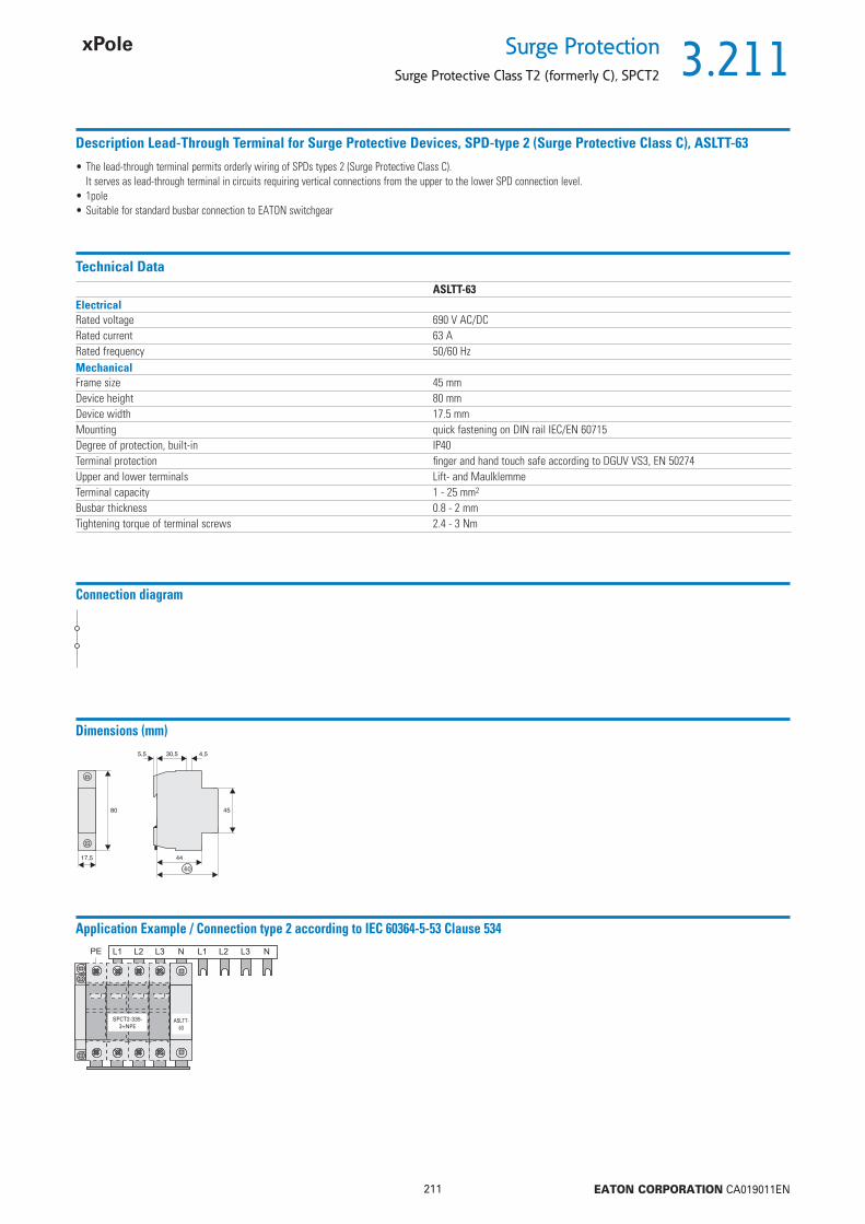
3.211
211 EATON CORPORATION CA019011EN
Surge ProtectionSurge Protective Class T2 (formerly C), SPCT2
Description Lead-Through Terminal for Surge Protective Devices, SPD-type 2 (Surge Protective Class C), ASLTT-63
• The lead-through terminal permits orderly wiring of SPDs types 2 (Surge Protective Class C). It serves as lead-through terminal in circuits requiring vertical connections from the upper to the lower SPD connection level.• 1pole• Suitable for standard busbar connection to EATON switchgear
Technical DataASLTT-63
ElectricalRated voltage 690 V AC/DCRated current 63 ARated frequency 50/60 HzMechanicalFrame size 45 mmDevice height 80 mmDevice width 17.5 mmMounting quick fastening on DIN rail IEC/EN 60715Degree of protection, built-in IP40Terminal protection fi nger and hand touch safe according to DGUV VS3, EN 50274Upper and lower terminals Lift- and MaulklemmeTerminal capacity 1 - 25 mm2
Busbar thickness 0.8 - 2 mmTightening torque of terminal screws 2.4 - 3 Nm
Dimensions (mm)
Connection diagram
Application Example / Connection type 2 according to IEC 60364-5-53 Clause 534
SPCT2-335-3+NPE
ASLTT-63

3.212
212 EATON CORPORATION CA019011EN
Surge Protection
Surge Protective Class T3 (formerly D), SPDT3
Poles Max. Continous Operating VoltageUC
TypeDesignation
Article No. Units perpackage
1pole+N 335 VAC SPDT3-335-1+NPE 170487 1/602pole 280 VAC SPDT3-280/2 170485 1/60
Surge arrester SPDT3SG03213
SPDT3-335-1+NPE
Complete (2-pole surge arresters are supplied with busbar)
280 VAC SPDT3-280 170484 2/120335 VAC SPDT3-335 170486 2/120
Surge arrester SPDT3, Insertsg03413
Insert 1pole
Max. Continous Operating VoltageUC
TypeDesignation
Article No. Units perpackage

3.213
213 EATON CORPORATION CA019011EN
Surge ProtectionSurge Protective Class T3 (formerly D), SPDT3
Description Surge Protective Class T3
• Field of application: For fi ne protection of user equipment against transient overvoltage• For mounting on DIN rails in distribution boxes for electrical installation• No decoupling from upstream surge protection in the low voltage distribution system required• Test class III according to IEC 61643-1+A1• SPD-type T3 according to EN 61643-11• Suitable for high back-up fuse 63 A gL / C 63• Auxiliary switch ASAUXSC-SPM for remote message transmission can be mounted onto the device
Technical DataSPDT3-335-1+NPE SPDT3-280/2
ElectricalMechanical coding yx xxResponding time (rate of voltage rise 5 kV/μs) L-N/N-PE/L-PE < 25ns/< 100ns/< 100ns L1-L2(N)/L2(N)-PE/L1-PE < 25nsMax. continuous operating voltage UC L-N/N-PE 335VAC/260VAC L1-L2(N)/L2(N)-PE 280VACTOV test value UT
5 s L-N/L-PE 350VAC/416VAC L-N/L-PE 350VAC/416VAC200 ms N-PE 1200VAC N-PE 1200VAC
Rated frequency 50/60 Hz 50/60 HzOpen circuit voltage UOC L-N/N-PE/L-PE 6kV L1-L2(N)/L2(N)-PE/L1-PE 6kVVoltage protection level at UOC Up L-N/N-PE/L-PE 900V/1500V/900V L1-L2(N)/L2(N)-PE 900VNominal discharge current (8/20) μs In L-N/N-PE/L-PE 2.5kA L1-L2(N)/L2(N)-PE 5kAVoltage protection level at In Up L-N/N-PE/L-PE 1000V/1500V/1000V L1-L2(N)/L2(N)-PE 950VMax. discharge current (8/20) μs Imax L-N/N-PE/L-PE 10kA L1-L2(N)/L2(N)-PE/L1-PE 10kAFollow current interrupt rating Ifi N-PE 100 Ar.m.s. –Maximum back-up fuseMaximum short-circuit current 125 AgL
50 kAr.m.s.
C63 10 kAr.m.s.
Connection diagram
MechanicalMechanical coding of base yx xxFrame size 45 mm 45 mmDevice height 80 mm 80 mmDevice width 35 mm 35 mmWeight 220 g 220 gPermitted ambient temperature -40°C to +70°C -40°C to +70°CDegree of protection (built-in) IP40 IP40Upper and lower lift terminal capacity 1 - 25 mm2 1 - 25 mm2
Upper and lower open mouthed terminals for busbar thickness up to 1.5 mm 1.5 mmTightening torque of terminal screws 2.4 - 3 Nm 2.4 - 3 NmQuick fastening on DIN rail according to IEC/EN 60715 IEC/EN 60715
x x
y y
Dimensions (mm) Application Examples

3.214
214 EATON CORPORATION CA019011EN
Surge Protection
Surge Protective Class T3 (formerly D)
Description TypeDesignation
Article No. Units perpackage
19“ Multiple Outlet Strips with Surge Protection SPD-STL/19/7F-S/BLwa_nt06613 7outlets plus switch,, DIN SPD-STL/19/7F-S/BL 283449 1
7outlets, UTE SPD-STL/19/7F-S/BL/UTE 290032 1
Description 19“ Multiple Outlet Strips with Surge Protection SPD-STL/19/7F-S/BL
• Can be mounted on 19“ rails• Installation height: 1U• Diagonally arranged socket outlets with earthing contact according to DIN 49440 or NF-C61314 (UTE), 16 A / 250 V AC• Connection cable of 2.5 m H05VV-F 3G 1.5 mm2 with an angled connector • On/Off switch, 2-pole, lit• Max. power consumption: 3680 W• Degree of protection: IP20• Temperature range: -5 up to +40 °C• Surge protection tested according to IEC 61643-1 (Class: SPD Type 3)• Response time: < 25 ns• Dimensions: 482.6x44x44.45 mm (WxDxH)• Material: Enclosure made of aluminium, front cover made of plastic similar to RAL 7035• Weight: approx. 0.9 kg• Scope of delivery: 1 Outlet strip incl. 19“ fi xing bracket, different fi xing material
Description TypeDesignation
Article No. Units perpackage
Surge Protection Multiple Outlet Strips with High-Range Filter and Energy Absorption for full Equipment Protection SPD-STL/6F-S
N04011 4 outlets plus switch, DIN Eaton Protection Strip 4 DIN PS4D 16 outlets plus switch, DIN Eaton Protection Strip 6 DIN PS6D 16 outlets plus switch, DIN+ISDN Eaton Protection Strip 6 Tel@ DIN PS6T 119“ fi xing bracket for SPD-STL/6F-S (1U) NWS-HW/19/SPD-STL/6F-S 166364 1
Description Surge Protection Multiple Outlet Strips with High-Range Filter and Energy Absorption for full Equipment Protection SPD-STL/6F-S• Suitable for wall-mounting in indoor areas• A 19“ fi xing bracket is available as an option for mounting the strip in a cabinet • Diagonally arranged socket outlets with earthing contact according to DIN 49440, 10 A / 250 V AC • Connection cable of 1.0 m H05VV-F 3G 1.0 mm2 with an angled connector• On/Off switch with MCB that can be reset • Max. power consumption: 2500 W• Degree of protection: IP20• Temperature range: -15 to +70 °C• Surge protection tested according to IEC 61643-1 (Class: SPD Type 3)• Response time: < 1 ns• Dimensions: 390x42x52 mm (WxDxH)• Material: Enclosure made of plastic similar to RAL 7021 • Weight: approx. 0.4 kg• Scope of delivery: 1 Multiple outlet strip

3.215
215 EATON CORPORATION CA019011EN
Surge ProtectionPhotovoltaic SPD Class T2
ACDC
Max. continuous operating voltage UC
TypeDesignation
Article No. Units perpackage
Plug-in Surge Arrester SPPVT2 for Photovoltaic application
sg04914
600 V DC SPPVT2-06-2+PE 176088 1 / 401000 V DC SPPVT2-10-2+PE 176090 1 / 40
• For insulationed and earthed systems
600 V DC SPPVT2-06-2+PE-AX 176087 1 / 401000 V DC SPPVT2-10-2+PE-AX 176089 1 / 40
With auxiliary switch
sg04714
600 V DC SPPVT2-06 176091 1 / 501000 V DC SPPVT2-10 176092 1 / 50
Inserts for replacement
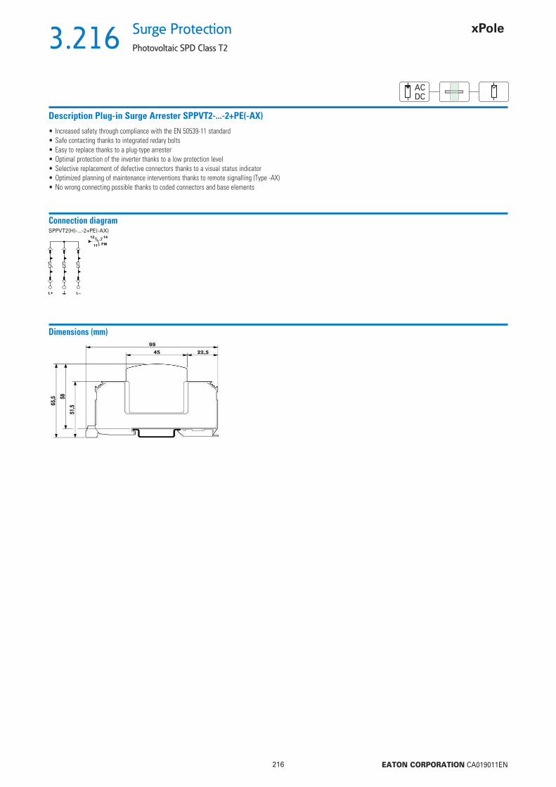
3.216
216 EATON CORPORATION CA019011EN
Surge Protection
Photovoltaic SPD Class T2
ACDC
Description Plug-in Surge Arrester SPPVT2-...-2+PE(-AX)
• Increased safety through compliance with the EN 50539-11 standard• Safe contacting thanks to integrated redary bolts• Easy to replace thanks to a plug-type arrester• Optimal protection of the inverter thanks to a low protection level• Selective replacement of defective connectors thanks to a visual status indicator• Optimized planning of maintenance interventions thanks to remote signalling (Type -AX)• No wrong connecting possible thanks to coded connectors and base elements
Connection diagram
12 14
11 FM
L–L+
SPPVT2(H)-...-2+PE(-AX)
Dimensions (mm)

3.217
217 EATON CORPORATION CA019011EN
Surge ProtectionPhotovoltaic SPD Class T2
ACDC
Technical DataSPPVT2-06-2+PE(-AX) SPPVT2-10-2+PE(-AX)
Environmental conditionDegree of protection IP20 IP20Ambient temperature of operation -40 ... +80°C -40 ... +80°CAltitude 2000 m 2000 mAllowed range of air humidity of operation 5 ... 95 % 5 ... 95 %GeneralStandards/regulations EN 50539-11 EN 50539-11EN Test class PV T2 PV T2SPD failure performance OCM OCMMounting DIN rail 35 mm DIN rail 35 mmMaterial of the enclosure PBT/PA PBT/PAPollution degree II IIFlammabilty class according to UL 94 V0 V0Signal for surge protection defective visual, with remote signalling contact visual, with remote signalling contactPredective circuit on the direct current side (DC)Max. continuous operating voltage UCPV 800 V DC 1170 V DCNo-load output voltage UOCSTC 670 V DC 970 V DCShort-circuit current strength ISCPV 2000 A 2000 ANominal load current IL 80 A DC 80 A DCPredective conductor current IPE
DC 20 μA 20 μAAC 300 μA 250 μA
Standby power consumption PC 20 mVA 25 mVANominal discharge current (8/20) μs 15 kA 15 kAMaximum discharge current (8/20) μs Imax 40 kA 40 kATotal lightning discharge current (8/20) μs ITotal 40 kA 40 kAVoltage protection level (L+) - (L-) Up 2.7 kV 3.7 kVVoltage protection level (L+/L-) - PE Up 2.7 kV 3.7 kVResponding time tA 25 ns 25 nsSizeHight 99 mm 99 mmWidth 53.4 mm 53.4 mmDepth 65.5 mm 65.5 mmModule units (MU) 3 MU 3 MUWeight...+PE gross 313 g / net 288 g gross 337 g / net 311 g...+PE-AX gross 320 g / net 294 g gross 343 g / net 317 gConnection dataType of connection Screw connection Screw connectionLift terminal capacity
fl exible 1.5-25 mm2 1.5-25 mm2
solid 1.5-35 mm2 1.5-35 mm2
Bolt thread M5 M5Tightening torque 4.5 Nm 4.5 NmStripping length 16 mm 16 mmType of connection Biconnect-terminals Biconnect-terminalsLift terminal capacity
solid 1.5-16 mm2 1.5-16 mm2
Bolt thread M6 M6Tightening torque 30 lb in 30 lb inAuxiliary SwitchSwitching function CO, 1-pole CO, 1-poleRated operational voltage 5 ... 250 V AC, 30 V DC 5 ... 250 V AC, 30 V DCRated operational current 5 mA ... 1.5 A AC, 1.5 A DC 5 mA ... 1.5 A AC, 1.5 A DCType of connection MC 1.5/3 MC 1.5/3Lift terminal capacity
fl exible 0.14-1.5 mm2 0.14-1.5 mm2
solid 0.14-1.5 mm2 0.14-1.5 mm2
Lift terminal capacity AWG/kcmil 30 ... 14 30 ... 14Bolt thread M2 M2Tightening torque 0.25 Nm, 2 ... 4 lb in 0.25 Nm, 2 ... 4 lb inStripping length 7 mm 7 mm

3.218
218 EATON CORPORATION CA019011EN
Surge Protection
Photovoltaic SPD Class T1/T2
ACDCACDC
Max. continuous operating voltage UC
TypeDesignation
Article No. Units perpackage
Plug-in Surge Arrester SPPVT12 for Photovoltaic application
sg04914
600 V DC SPPVT12-06-2+PE 177258 1 / 401000 V DC SPPVT12-10-2+PE 177256 1 / 40
• For insulationed and earthed systems
600 V DC SPPVT12-06-2+PE-AX 177257 1 / 401000 V DC SPPVT12-10-2+PE-AX 177255 1 / 40
With auxiliary switch
sg04714
600 V DC SPPVT12-06 177259 1 / 501000 V DC SPPVT12-10 177260 1 / 50
Inserts for replacement
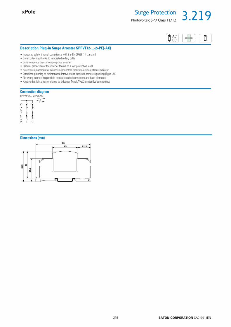
3.219
219 EATON CORPORATION CA019011EN
Surge ProtectionPhotovoltaic SPD Class T1/T2
ACDC
Description Plug-in Surge Arrester SPPVT12-...-2+PE(-AX)
• Increased safety through compliance with the EN 50539-11 standard• Safe contacting thanks to integrated redary bolts• Easy to replace thanks to a plug-type arrester• Optimal protection of the inverter thanks to a low protection level• Selective replacement of defective connectors thanks to a visual status indicator• Optimized planning of maintenance interventions thanks to remote signalling (Type -AX)• No wrong connecting possible thanks to coded connectors and base elements• Always the right arrester thanks to universal Type1/Type2 predective components
Connection diagram
Dimensions (mm)
12 14
11 FM
L–L+
SPPVT12-...-2+PE(-AX)

3.220
220 EATON CORPORATION CA019011EN
Surge Protection
Photovoltaic SPD Class T1/T2
ACDCACDC
Technical DataSPPVT12-06-2+PE(-AX) SPPVT12-10-2+PE(-AX)
Environmental conditionDegree of protection IP20 IP20Ambient temperature of operation -40 ... +80°C -40 ... +80°CAltitude 2000 m 2000 mAllowed range of air humidity of operation 5 ... 95 % 5 ... 95 %GeneralStandards/regulations EN 50539-11 EN 50539-11EN Test class PV T1/PV T2 PV T1/PV T2SPD failure performance OCM OCMMounting DIN rail 35 mm DIN rail 35 mmMaterial of the enclosure PBT/PA PBT/PAPollution degree II IIFlammabilty class according to UL 94 V0 V0Signal for surge protection defective visual, with remote signalling contact visual, with remote signalling contactPredective circuit on the direct current side (DC)Max. continuous operating voltage UCPV 720 V DC 1050 V DCNo-load output voltage UOCSTC 600 V DC 875 V DCShort-circuit current strength ISCPV 2000 A 2000 ANominal load current IL 80 A DC 80 A DCPredective conductor current IPE
DC 20 μA 20 μAAC 350 μA 350 μA
Standby power consumption PC 20 mVA 25 mVANominal discharge current (8/20) μs 15 kA 15 kAMaximum discharge current (8/20) μs Imax 40 kA 40 kALightning test current (10/350) μs, Peak current Iimp 5 kA 5 kATotal lightning discharge current (8/20) μs ITotal 7 kA 5 kAVoltage protection level (L+) - (L-) Up 2.6 kV 357 kVVoltage protection level (L+/L-) - PE Up 2.6 kV 3.5 kVResponding time tA 25 ns 25 nsRequired max. back-up fuse with stub-line wiring not neccessary not neccessarySizeHight 99 mm 99 mmWidth 53.4 mm 53.4 mmDepth 65.5 mm 65.5 mmModule units (MU) 3 MU 3 MUWeight...+PE gross 407 g / net 379 g gross 407 g / net 379 g...+PE-AX gross 414 g / net 386 g gross 414 g / net 386 gConnection dataType of connection Screw connection Screw connectionLift terminal capacity
fl exible 1.5-25 mm2 1.5-25 mm2
solid 1.5-35 mm2 1.5-35 mm2
Bolt thread M5 M5Tightening torque 4.5 Nm 4.5 NmStripping length 16 mm 16 mmType of connection Biconnect-terminals Biconnect-terminalsLift terminal capacity
solid 1.5-16 mm2 1.5-16 mm2
Bolt thread M6 M6Tightening torque 30 lb in 30 lb inAuxiliary SwitchSwitching function CO, 1-pole CO, 1-poleRated operational voltage 5 ... 250 V AC, 30 V DC 5 ... 250 V AC, 30 V DCRated operational current 5 mA ... 1.5 A AC, 1.5 A DC 5 mA ... 1.5 A AC, 1.5 A DCType of connection MC 1.5/3 MC 1.5/3Lift terminal capacity
fl exible 0.14-1.5 mm2 0.14-1.5 mm2
solid 0.14-1.5 mm2 0.14-1.5 mm2
Lift terminal capacity AWG/kcmil 30 ... 14 30 ... 14Bolt thread M2 M2Tightening torque 0.25 Nm, 2 ... 4 lb in 0.25 Nm, 2 ... 4 lb inStripping length 7 mm 7 mm

3.221
221 EATON CORPORATION CA019011EN
Surge ProtectionBusbar
Poles TypeDesignation
Article No. Units perpackage
Busbar Z-GV-U/ for SPI, SP-B+C
Z-GV-U/9
2 Z-GV-U/2 272588 20 / 12003 Z-GV-U/3 272589 20 / 12004 Z-GV-U/4 274080 20 / 12005 Z-GV-U/5 274081 20 / 12006 Z-GV-U/6 274082 20 / 4008 Z-GV-U/8 274083 20 / 2009 Z-GV-U/9 274084 20 / 200
Description busbar Z-GV-U/
• Busbars Z-GV-U/ permit to implement customary SPD combinations• Suitable for SPI-..., SPB-D-125• The rated cross-section of Z-GV-U/ is 16 mm2
• The busbars must be cut to length in some cases
Technical DataZ-GV-U/
ElectricalRated voltage 230/400 V, 50/60 HzRated current 63 AMechanicalBusbar cross section 16 mm2 Cu
Design

3.222
222 EATON CORPORATION CA019011EN
Surge Protection
Busbar
Used for TypeDesignation
Article No. Units perpackage
Busbar Z-GV-16/3P-3TE/6WA_SG11202 for SPI and SPC Z-GV-16/3P-3TE/6 267511 12 / 240
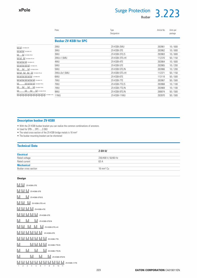
3.223
223 EATON CORPORATION CA019011EN
Surge ProtectionBusbar
Poles TypeDesignation
Article No. Units perpackage
Busbar ZV-KSBI for SPC 2MU ZV-KSBI-2MU 263961 10 / 600
3MU ZV-KSBI-3TE 263962 10 / 6003MU ZV-KSBI-3TE/S 263963 10 / 6002MU+1.5MU ZV-KSBI-3TE+HI 112370 50 / 1504MU ZV-KSBI-4TE 263964 10 / 6005MU ZV-KSBI-5TE 263965 10 / 2005MU ZV-KSBI-5TE/N 263966 10 / 2002MU+3x1.5MU ZV-KSBI-5TE+HI 112371 50 / 1506MU ZV-KSBI-6TE 113118 50 / 5007MU ZV-KSBI-7TE 263967 50 / 5007MU ZV-KSBI-7TE/S 263968 10 / 1007MU ZV-KSBI-7TE/N 263969 10 / 1009MU ZV-KSBI-9TE/N 266874 50 / 50011MU ZV-KSBI-11MU 263970 50 / 500
Description busbar ZV-KSBI
• With the ZV KSBI busbar bracket you can realize the common combinations of arrestors.• Used for SPB-..., SPC-..., Z-D63• The rated cross-section of the ZV-KSBI bridge metals is 16 mm2
• The busbar mounting bracket can be shortened
Technical DataZ-GV-U/
ElectricalRated voltage 230/400 V, 50/60 HzRated current 63 AMechanicalBusbar cross section 16 mm2 Cu
Design
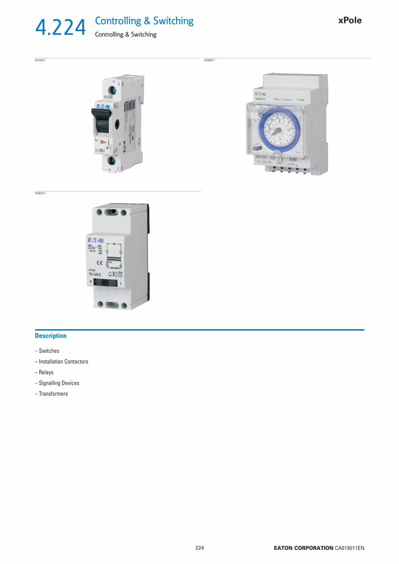
4.224
224 EATON CORPORATION CA019011EN
Controlling & Switching
Controlling & Switching
SG10611
– Switches
– Installation Contactors
– Relays
– Signalling Devices
– Transformers
Description
SG83911
SG82911

4.225
225 EATON CORPORATION CA019011EN
Controlling & SwitchingMain Load Disconnector Switch (Isolator) IS
Main Load Disconnector Switch (Isolator) IS
Rated current (A)
Poles TypeDesignation
Article No. Units perpackage
SG10611 16 1 IS-16/1 276254 12/12016 2 IS-16/2 276255 1/6016 3 IS-16/3 276256 1/4016 4 IS-16/4 276257 1/3020 1 IS-20/1 276258 12/12020 2 IS-20/2 276259 1/6020 3 IS-20/3 276260 1/4020 4 IS-20/4 276261 1/3025 1 IS-25/1 276262 12/12025 2 IS-25/2 276263 1/6025 3 IS-25/3 276264 1/4025 4 IS-25/4 276265 1/3032 1 IS-32/1 276266 12/12032 2 IS-32/2 276267 1/6032 3 IS-32/3 276268 1/4032 4 IS-32/4 276269 1/3040 1 IS-40/1 276270 12/12040 2 IS-40/2 276271 1/6040 3 IS-40/3 276272 1/4040 4 IS-40/4 276273 1/3063 1 IS-63/1 276274 12/12063 2 IS-63/2 276275 1/6063 3 IS-63/3 276276 1/4063 4 IS-63/4 276277 1/3080 1 IS-80/1 276278 12/12080 2 IS-80/2 276279 1/6080 3 IS-80/3 276280 1/4080 4 IS-80/4 276281 1/30100 1 IS-100/1 276282 12/120100 2 IS-100/2 276283 1/60100 3 IS-100/3 276284 1/40100 4 IS-100/4 276285 1/30125 1 IS-125/1 276286 12/120125 2 IS-125/2 276287 1/60125 3 IS-125/3 276288 1/40125 4 IS-125/4 276289 1/30
SG10711
SG10811
SG10911
Accessories
Switching interlock IS/SPE-1MU• Without lock• Also suitable for PFIM, CFI6, PKNM, CKN6
SG47812 Switching interlock without lock for Isolators, RCDs, combined RCD/MCBs, ...
IS/SPE-1MU 101911 5/30
Description TypeDesignation
Article No. Units perpackage
sg01215 Terminal cover Z-IS/AK-1MU 276290 10/600
Terminal cover Z-IS/AK-1MU• Can be sealed with leads• Modular design, width 1 MU
PHASE OUT

4.226
226 EATON CORPORATION CA019011EN
Controlling & Switching
Main Load Disconnector Switch (Isolator) IS
Description Main Load Disconnector Switch (Isolator) IS
• Load circuit breaker with isolating function• Design according to IEC/EN 60947-3• Highly wear resistant contacts• Quick make, black toggle• Terminal capacity 50 mm2
• Compatible busbars with switchgear series Xpole by use of the mouth terminal in combination with standard fork busbar
Technical DataIS-16 IS-20 IS-25 IS-32 IS-40 IS-63 IS-80 IS-100 IS-125
ElectricalDesign according to IEC/EN 60947-3Rated voltage 240/415 VFrequency 50/60 HzRated insulation voltage Ui 690 V~Rated peak withstand voltage Uimp 6 kVPollution degree 3Rated short-time withstand current Icw 2 kARated short-circuit making capacity Icm 2.8 kARated current 240/415 V, AC23A 16 A 20 A 25 A 32 A 40 A 63 A 80 A 100 A 125 ANumber of poles 1-, 2-, 3-, 4-poleMaximum back-up fuse 125 A gGShort-circuit current strength - with back-up fuse according to IEC/EN 60947-3 12.5 kA 12.5 kA 12.5 kA 12.5 kA 12.5 kA 12.5 kA 12.5 kA 10 kA 10 kAEndurance
operating cycles electrical components 3,000 3,000 3,000 3,000 3,000 3,000 3,000 3,000 2,000operating cycles mechanical components 16,000 16,000 16,000 16,000 16,000 16,000 16,000 16,000 14.000
MechanicalFrame size 45 mmDevice height 80 mmDevice width 17.5mm/poleMounting quick fastening with 2 lock-in positions on DIN rail IEC/EN 60715Degree of protection, built-in IP40Terminal protection fi nger and hand touch safe according to DGUV VS3, EN 50274Upper and lower terminals Twin-purpose terminalsTerminal capacity 2.5 - 50 mm2
Busbar thickness 0.8 - 2 mmTightening torque of terminal screws 2.5 - 5 NmFunction irrespective of the position of installation
Connection diagram1-pole 2-pole 3-pole 4-pole
Dimensions (mm)
Anti-tamper deviceIS/SPE1MU
Terminal coverZ-IS/AK-1MU

4.227
227 EATON CORPORATION CA019011EN
Controlling & SwitchingCircuit Breaker ZP-A
Circuit Breaker ZP-A
Poles Rated current (A)
TypeDesignation
Article No. Units perpackage
SG00912 1 40 ZP-A40/1 248263 12 / 1202 40 ZP-A40/2 248264 1 / 603 40 ZP-A40/3 248265 1 / 403+N 40 ZP-A40/3N 248266 1 / 301 63 ZP-A63/1 284906 12 / 1202 63 ZP-A63/2 284907 1 / 603 63 ZP-A63/3 284908 1 / 403+N 63 ZP-A63/3N 284909 1 / 30
Accessories:Auxiliary switch for subsequent installation ZP-IHK 286052
ZP-WHK 286053Tripping signal contact for subsequent installation ZP-NHK 248437Shunt trip release ZP-ASA/.. 248438, 248439Undervoltage release Z-USA/.. 248288-248291Additional terminal 35 mm2 Z-HA-EK/35 263960Anti-tamper device Z-IS/SPE-1MU 274418
Description Circuit Breaker ZP-A
• Design according to IEC/EN 60947-1, -3• Poles: 1, 2, 3, 3N• Rated current: 40 A, 63 A• Accessories for switchgear also for ZP-A usable!
Technical DataZP-A
ElectricalRated operational voltage Ue 230/400 V ACRated frequency 50 HzRated insulation voltage UI 440 V ACRated peak withstand voltage (1.2/50 μS) Uimp 4 kVConventional thermal current Ith
ZP-A40 40 AZP-A63 63 A
Utilisation category AC22AMinimum voltage per contact IeZP-A40 40 A ACZP-A63 63 A AC
Utilisation category AC23AMinimum voltage per contact Ie 16 A AC
Short-circuit current strength with back-up fuse 40 A gG 3 kA (U = 240 V, cos = 0.87)Endurance
electrical components 8,000 switching operationsmechanical components 20,000 switching operations
MechanicalFrame size 45 mmDevice height 80 mmDevice width 17.5mm/poleMounting quick fastening on DIN rail IEC/EN 60715Degree of protection, built-in IP40Terminal protection fi nger and hand touch safe according to DGUV VS3, EN 50274Upper and lower terminals lift terminals + guide for secure terminalTerminal capacity 1.5-25 mm2
Terminal screws M5 (Pozidrive) Z2Tightening torque of terminal screws max. 2.4 Nm

4.228
228 EATON CORPORATION CA019011EN
Controlling & Switching
Circuit Breaker ZP-A
Connection diagram1pole 2pole 3pole 3+Npole
Dimensions (mm)
Practical Hint Practical Hint
e.g. 16(2)A .... Ratings for resistive/inductive consumers
ÖVE-SN45, § 305
....... Ratings for incandescent lamp load (AC 5b IEC 60947-4)
ÖVE-SN45, § 207, IEC 60947-3
Switching contactin general
Switch with reduced air gap
Power circuit breaker
Disconnector
Load disconnector switch
Fuse power circuit breaker
Fuse disconnector
Fuse switch disconnector

4.229
229 EATON CORPORATION CA019011EN
Controlling & SwitchingMCB for Auxiliary Switch Circuits PL7-B4/.-HS
MCB for Auxiliary Switch Circuits PL7-B4/.-HS
Poles Rated Breaking Capacity(kA)
TypeDesignation
Article No. Units perpackage
wa_sg06113 1 10 PL7-B4-HS 264908 2 / 1201+N 10 PL7-B4/1N-HS 264909 2 / 802 10 PL7-B4/2-HS 264910 1 / 60
Description MCB for Auxiliary Switch Circuits PL7-B4/.-HS
• Compliant with EN 60898, 4 A, Characteristic B • A very low I2t short-circuit value limits contact wear in auxiliary contacts • Fully compatible with PL7, PF7, ...
Technical DataPL7-B4/.-HS
ElectricalNumber of poles 1-, 1+N-, 2poleRated voltage 230/400 VFrequency 50/60 HzRated current 4 ARated breaking capacity 10 kAMechanicalFrame size 45 mmDevice height 80 mmDevice width 17.5 mm (1MU) / 26.3 mm / 35 mm (2MU)Mounting quick fastening with 2 lock-in positions on DIN rail IEC/EN 60715Degree of protection, built-in IP40Terminal protection fi nger and hand touch safe according to DGUV VS3, EN 50274Terminals Twin-purpose terminalsTerminal capacity 1-25 mm2
Terminal screws M3 (Pozidrive)Tightening torque of terminal screws 0.8-1.0 NmBusbar thickness 0.8 - 2 mm
Connection diagrame.g. 1pole
Dimensions (mm)PL7-B4/.-HS

4.230
230 EATON CORPORATION CA019011EN
Controlling & Switching
MCB for Auxiliary Switch Circuits PL7-B4/.-HS
Even auxiliary switches must be predected against overload and short circuit by means of suitable back-up fuses according to manufacturer specifi cation. According to IEC 60947-5 a maximum back-up fuse is specifi ed for conditional short circuit prevention up to 1,000 A. Therefore, connection of the auxiliary switch to the nearest MCB is not permitted. Danger of contact welding! The MCB for auxiliary switch circuits ...-HS offers a simple solution.
Practical HintLet-through Energy PL7-B4-HS
Let-through Energy PL7-B4-HS, Characteristic B, 1pole
Prospective short-circuit current [A]
Let
thro
ugh
ener
gy I2
t [A
2 se
c]

4.231
231 EATON CORPORATION CA019011EN
Controlling & SwitchingPushbutton Z-T/; Control Switch Z-S../; Changeover Switch Z-S/.W
Pushbutton Z-T/
Colour Pushbutton/Function TypeDesignation
Article No. Units perpackage
SG37112 green 4NO Z-T/4S-G 248328 12 / 120black 3NO+1NC Z-T/3S1O 248330 12 / 120
Control Switch Z-S../
Rated current(A)
Function TypeDesignation
Article No. Units perpackage
SG38912 16 3NO Z-S/3S 248334 12 / 12016 4NO Z-S/4S 248335 12 / 12016 2NO+2NC Z-S/SSOO 248337 12 / 12016 3NO+1NC Z-S/3S1O 248338 12 / 120
Changeover Switch Z-S/.W
Function TypeDesignation
Article No. Units perpackage
SG39012 1CO I-0-II Z-S/WM 248345 12 / 1202CO I-0-II Z-S/2WM 248346 12 / 1201CO DAY-0-NIGHT Z-S/WTN 248347 12 / 1202CO DAY-0-NIGHT Z-S/2WTN 248348 12 / 120
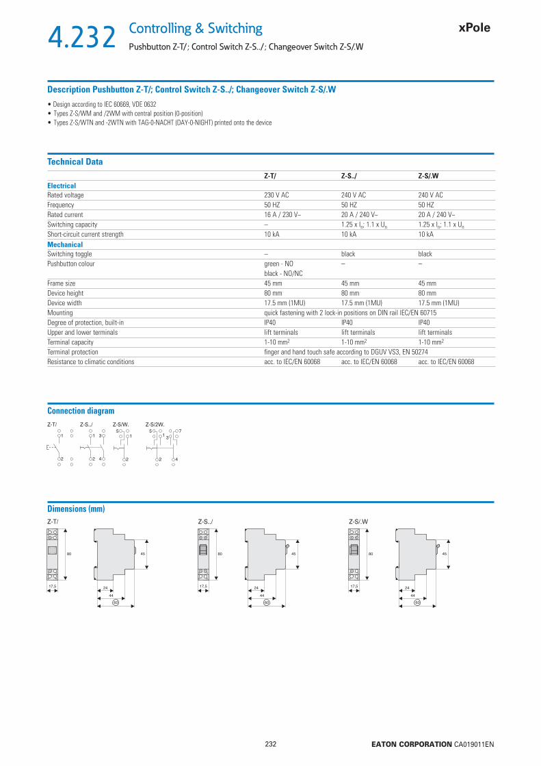
4.232
232 EATON CORPORATION CA019011EN
Controlling & Switching
Pushbutton Z-T/; Control Switch Z-S../; Changeover Switch Z-S/.W
Description Pushbutton Z-T/; Control Switch Z-S../; Changeover Switch Z-S/.W
• Design according to IEC 60669, VDE 0632• Types Z-S/WM and /2WM with central position (0-position)• Types Z-S/WTN and -2WTN with TAG-0-NACHT (DAY-0-NIGHT) printed onto the device
Technical DataZ-T/ Z-S../ Z-S/.W
ElectricalRated voltage 230 V AC 240 V AC 240 V ACFrequency 50 HZ 50 HZ 50 HZRated current 16 A / 230 V~ 20 A / 240 V~ 20 A / 240 V~Switching capacity – 1.25 x In; 1.1 x Un 1.25 x In; 1.1 x Un
Short-circuit current strength 10 kA 10 kA 10 kAMechanicalSwitching toggle – black blackPushbutton colour green - NO – –
black - NO/NCFrame size 45 mm 45 mm 45 mmDevice height 80 mm 80 mm 80 mmDevice width 17.5 mm (1MU) 17.5 mm (1MU) 17.5 mm (1MU)Mounting quick fastening with 2 lock-in positions on DIN rail IEC/EN 60715Degree of protection, built-in IP40 IP40 IP40Upper and lower terminals lift terminals lift terminals lift terminalsTerminal capacity 1-10 mm2 1-10 mm2 1-10 mm2
Terminal protection fi nger and hand touch safe according to DGUV VS3, EN 50274Resistance to climatic conditions acc. to IEC/EN 60068 acc. to IEC/EN 60068 acc. to IEC/EN 60068
Connection diagramZ-T/ Z-S../ Z-S/W. Z-S/2W.
Dimensions (mm)Z-T/ Z-S/.WZ-S../
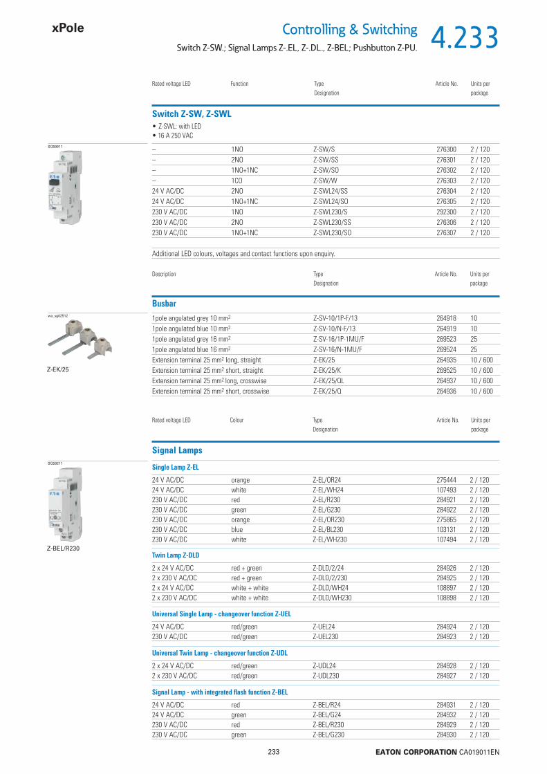
4.233
233 EATON CORPORATION CA019011EN
Controlling & SwitchingSwitch Z-SW.; Signal Lamps Z-.EL, Z-.DL., Z-BEL; Pushbutton Z-PU.
Switch Z-SW, Z-SWL
Rated voltage LED Function TypeDesignation
Article No. Units perpackage
SG59911 – 1NO Z-SW/S 276300 2 / 120– 2NO Z-SW/SS 276301 2 / 120– 1NO+1NC Z-SW/SO 276302 2 / 120– 1CO Z-SW/W 276303 2 / 12024 V AC/DC 2NO Z-SWL24/SS 276304 2 / 12024 V AC/DC 1NO+1NC Z-SWL24/SO 276305 2 / 120230 V AC/DC 1NO Z-SWL230/S 292300 2 / 120230 V AC/DC 2NO Z-SWL230/SS 276306 2 / 120230 V AC/DC 1NO+1NC Z-SWL230/SO 276307 2 / 120
Additional LED colours, voltages and contact functions upon enquiry.
• Z-SWL: with LED• 16 A 250 VAC
Busbarwa_sg02512 1pole angulated grey 10 mm2 Z-SV-10/1P-F/13 264918 10
1pole angulated blue 10 mm2 Z-SV-10/N-F/13 264919 101pole angulated grey 16 mm2 Z-SV-16/1P-1MU/F 269523 251pole angulated blue 16 mm2 Z-SV-16/N-1MU/F 269524 25Extension terminal 25 mm2 long, straight Z-EK/25 264935 10 / 600Extension terminal 25 mm2 short, straight Z-EK/25/K 269525 10 / 600Extension terminal 25 mm2 long, crosswise Z-EK/25/QL 264937 10 / 600Extension terminal 25 mm2 short, crosswise Z-EK/25/Q 264936 10 / 600
Description TypeDesignation
Article No. Units perpackage
Z-EK/25
Rated voltage LED Colour TypeDesignation
Article No. Units perpackage
24 V AC/DC orange Z-EL/OR24 275444 2 / 12024 V AC/DC white Z-EL/WH24 107493 2 / 120230 V AC/DC red Z-EL/R230 284921 2 / 120230 V AC/DC green Z-EL/G230 284922 2 / 120230 V AC/DC orange Z-EL/OR230 275865 2 / 120230 V AC/DC blue Z-EL/BL230 103131 2 / 120230 V AC/DC white Z-EL/WH230 107494 2 / 120
Signal LampsSG59211
Z-BEL/R230
Single Lamp Z-EL
2 x 24 V AC/DC red + green Z-DLD/2/24 284926 2 / 1202 x 230 V AC/DC red + green Z-DLD/2/230 284925 2 / 1202 x 24 V AC/DC white + white Z-DLD/WH24 108897 2 / 1202 x 230 V AC/DC white + white Z-DLD/WH230 108898 2 / 120
Twin Lamp Z-DLD
24 V AC/DC red/green Z-UEL24 284924 2 / 120230 V AC/DC red/green Z-UEL230 284923 2 / 120
Universal Single Lamp - changeover function Z-UEL
2 x 24 V AC/DC red/green Z-UDL24 284928 2 / 1202 x 230 V AC/DC red/green Z-UDL230 284927 2 / 120
Universal Twin Lamp - changeover function Z-UDL
24 V AC/DC red Z-BEL/R24 284931 2 / 12024 V AC/DC green Z-BEL/G24 284932 2 / 120230 V AC/DC red Z-BEL/R230 284929 2 / 120230 V AC/DC green Z-BEL/G230 284930 2 / 120
Signal Lamp - with integrated fl ash function Z-BEL
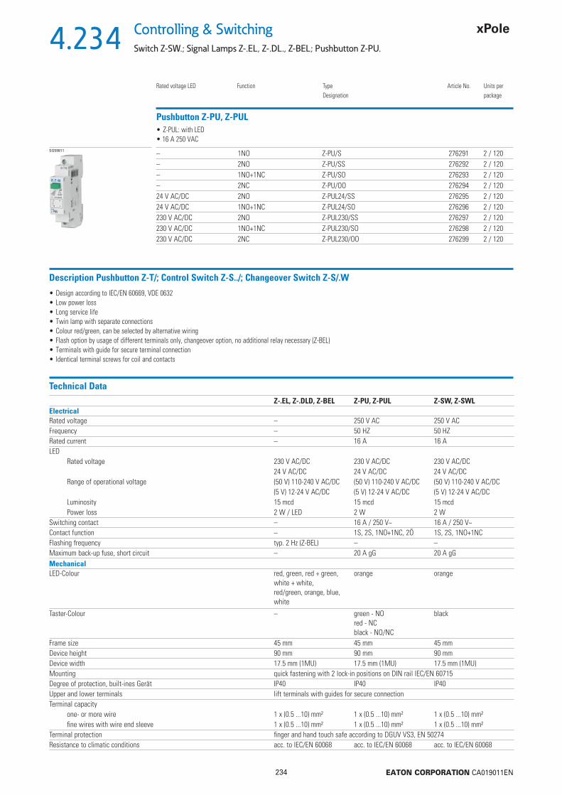
4.234
234 EATON CORPORATION CA019011EN
Controlling & Switching
Switch Z-SW.; Signal Lamps Z-.EL, Z-.DL., Z-BEL; Pushbutton Z-PU.
Pushbutton Z-PU, Z-PUL
Rated voltage LED Function TypeDesignation
Article No. Units perpackage
SG59811 – 1NO Z-PU/S 276291 2 / 120– 2NO Z-PU/SS 276292 2 / 120– 1NO+1NC Z-PU/SO 276293 2 / 120– 2NC Z-PU/OO 276294 2 / 12024 V AC/DC 2NO Z-PUL24/SS 276295 2 / 12024 V AC/DC 1NO+1NC Z-PUL24/SO 276296 2 / 120230 V AC/DC 2NO Z-PUL230/SS 276297 2 / 120230 V AC/DC 1NO+1NC Z-PUL230/SO 276298 2 / 120230 V AC/DC 2NC Z-PUL230/OO 276299 2 / 120
• Z-PUL: with LED• 16 A 250 VAC
Description Pushbutton Z-T/; Control Switch Z-S../; Changeover Switch Z-S/.W
• Design according to IEC/EN 60669, VDE 0632• Low power loss• Long service life• Twin lamp with separate connections• Colour red/green, can be selected by alternative wiring• Flash option by usage of different terminals only, changeover option, no additional relay necessary (Z-BEL)• Terminals with guide for secure terminal connection • Identical terminal screws for coil and contacts
Technical DataZ-.EL, Z-.DLD, Z-BEL Z-PU, Z-PUL Z-SW, Z-SWL
ElectricalRated voltage – 250 V AC 250 V ACFrequency – 50 HZ 50 HZRated current – 16 A 16 ALED
Rated voltage 230 V AC/DC 230 V AC/DC 230 V AC/DC24 V AC/DC 24 V AC/DC 24 V AC/DC
Range of operational voltage (50 V) 110-240 V AC/DC (50 V) 110-240 V AC/DC (50 V) 110-240 V AC/DC(5 V) 12-24 V AC/DC (5 V) 12-24 V AC/DC (5 V) 12-24 V AC/DC
Luminosity 15 mcd 15 mcd 15 mcdPower loss 2 W / LED 2 W 2 W
Switching contact – 16 A / 250 V~ 16 A / 250 V~Contact function – 1S, 2S, 1NO+1NC, 2Ö 1S, 2S, 1NO+1NCFlashing frequency typ. 2 Hz (Z-BEL) – –Maximum back-up fuse, short circuit – 20 A gG 20 A gGMechanicalLED-Colour red, green, red + green,
white + white,red/green, orange, blue,white
orange orange
Taster-Colour – green - NOred - NCblack - NO/NC
black
Frame size 45 mm 45 mm 45 mmDevice height 90 mm 90 mm 90 mmDevice width 17.5 mm (1MU) 17.5 mm (1MU) 17.5 mm (1MU)Mounting quick fastening with 2 lock-in positions on DIN rail IEC/EN 60715Degree of protection, built-ines Gerät IP40 IP40 IP40Upper and lower terminals lift terminals with guides for secure connectionTerminal capacity
one- or more wire 1 x (0.5 ...10) mm² 1 x (0.5 ...10) mm² 1 x (0.5 ...10) mm²fi ne wires with wire end sleeve 1 x (0.5 ...10) mm² 1 x (0.5 ...10) mm² 1 x (0.5 ...10) mm²
Terminal protection fi nger and hand touch safe according to DGUV VS3, EN 50274Resistance to climatic conditions acc. to IEC/EN 60068 acc. to IEC/EN 60068 acc. to IEC/EN 60068

4.235
235 EATON CORPORATION CA019011EN
Controlling & SwitchingSwitch Z-SW.; Signal Lamps Z-.EL, Z-.DL., Z-BEL; Pushbutton Z-PU.
Connection diagramZ-EL/OR Z-UEL (red/green) Z-UDL Z-PU Z-PUL Z-SW Z-SWL
Dimensions (mm)
Connection example for LED red/greenL(+) L(+) –> same potentialN(–) = neutral conductor
Changing of colour by connecting eitherR- or G-connector terminal.
or
red green
Connection example for BlinkfunktionL(+) L(+) –> same potentialN(–) = neutral conductor
Changing of function by connecting either X2- or X3-connector terminal.
or
red

4.236
236 EATON CORPORATION CA019011EN
Controlling & Switching
Rotary Switch Z-DS
Rotary Switch Z-DS
Function Position TypeDesignation
Article No. Units perpackage
SG85211 1pole OFF 0 - 1 Z-DSA1-01 248868 1 / 401pole CO 1 - 0 - 2 Z-DSU1-102 248869 1 / 401pole CO HA - 0 - AU Z-DSU1-H0A 248870 1 / 401pole CO TA - 0 - NA Z-DSU1-T0N 248871 1 / 402pole OFF 0 - 1 Z-DSA2-01 248872 1 / 402pole OFF 0 - 1 Z-DSA2-01-SL 248873 1 / 402pole CO 1 - 2 Z-DSU2-12 248874 1 / 402pole CO 1 - 0 - 2 Z-DSU2-102 248875 1 / 402pole CO HA - 0 - AU Z-DSU2-H0A 248876 1 / 403pole CO 1 - 0 - 2 Z-DSU3-102 248877 1 / 40Voltmeter L-N L1 - N... Z-DSV-LN 248878 1 / 40Voltmeter L-L L1 - L2... Z-DSV-LL 248879 1 / 40Voltmeter L+N L1 - N3... Z-DSV-LLLN 248880 1 / 40Ammeter 0-1-2-3 Z-DSAM-0123 129712 1 / 40
Z-DSU1-102
SG85311
Z-DSA2-01-SL
Description Rotary Switch Z-DS
• Rotary switches of series Z-DS are of a modular design:The switch proper consists of the engaging work and the switching package. The switching cams (for which it is also called cam switch) are driven by a stable, torsion-proof aluminium shaft. The switching package consists of one or several switching cells with one or two independent contacts. Connections of adjoining switch terminals (necessary in case of voltmeter changeover switch Z-DSV) are contained in the pressed switch component. Consequently, there is no obstacle when connecting the connection lines.
• Application:Suitable for virtually any application, e.g. motor switch, garage doors, fans, shutters, heating system control, lighting fi xtures, instrument switches, different control purposes, etc.

4.237
237 EATON CORPORATION CA019011EN
Controlling & SwitchingRotary Switch Z-DS
Technical DataZ-DS
Data according to IEC 60947-3, IEC 60947-5-1, VDE 0660, EN 60947-3, SEVNominal thermal current
open Ith 20 Ahermetically enclosed Ithg 20 A
Nominal operational voltage Ue 690 VRated peak withstand voltage Uimp 6 kVDisconnector conditions according toÖVE, IEC met up to 440 V
Circuit breaking capacity Iv3 x 220-440V 160 A3 x 500 V 100 A3 x 660-690V 80 A
Utilisation category AC21A, AC21BSwitching resistive loads including low overloadsNominal operational current In 20 A
Utilisation category AC23A, AC23BSwitching motors and other highly inductive loadsNominal operational current 400 V In 16 ANominal power 220-240 V 4 kW3phase 3pole 380-440 V 7.5 kW3phase 3pole 500 V 7.5 kW3phase 3pole 660-690 V 7.5 kW
Star-delta starting switchfor squirrel cage motorsNominal power3phase 3pole 220-240 V 3.7 kW3phase 3pole 380-415 V 7.5 kW
Utilisation category AC3Switching of 3phase AC motorsNominal operational current 400 V In 12 ANominal power 220-240 V 3 kW3phase 3pole 380-440 V 5.5 kW3phase 3pole 500 V 5.5 kW3phase 3pole 660-690 V 5.5 kW
Utilisation category AC15Switching of electromagnetic drives, contactors, valves, pull-type electromagnetsNominal operational current to 240 V In 6 ANominal operational current 380-440 V In 4 A2pole disconnection 500 V 5 A
Utilisation category DC21A, DC21BSwitching of resistive loads, time constant L/R 1 msNominal operational current In1pole 30 V 20 A1pole 60 V 4 A1pole 110 V 0.6 A1pole 220 V 0.3 A1pole 440 V –
Utilisation category DC3 - DC5Switching of shunt motors and series motors, time constant L/R 15 msNominal operational current In1pole 30 V 8 A1pole 60 V 1 A1pole 110 V 0.3 A
Terminal capacityone or several wires 1 - 2.5 mm2
fi ne-wire 0.75 - 2.5 mm2
fi ne wires with wire end sleeve 0.75 - 1.5 mm2
terminal screw M3.5number of conductors per terminal 2
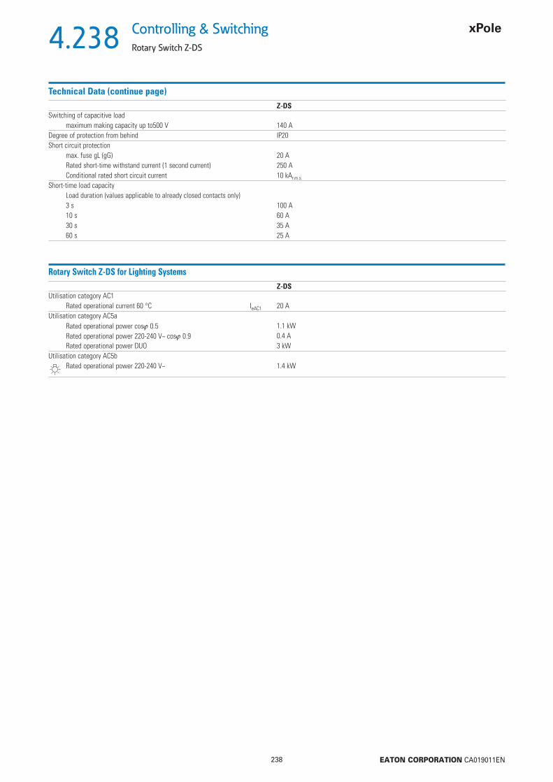
4.238
238 EATON CORPORATION CA019011EN
Controlling & Switching
Rotary Switch Z-DS
Technical Data (continue page)Z-DS
Switching of capacitive loadmaximum making capacity up to500 V 140 A
Degree of protection from behind IP20Short circuit protection
max. fuse gL (gG) 20 ARated short-time withstand current (1 second current) 250 AConditional rated short circuit current 10 kAr.m.s.
Short-time load capacityLoad duration (values applicable to already closed contacts only)3 s 100 A10 s 60 A30 s 35 A60 s 25 A
Rotary Switch Z-DS for Lighting SystemsZ-DS
Utilisation category AC1Rated operational current 60 °C IeAC1 20 A
Utilisation category AC5aRated operational power cos 0.5 1.1 kWRated operational power 220-240 V~ cos 0.9 0.4 ARated operational power DUO 3 kW
Utilisation category AC5bRated operational power 220-240 V~ 1.4 kW
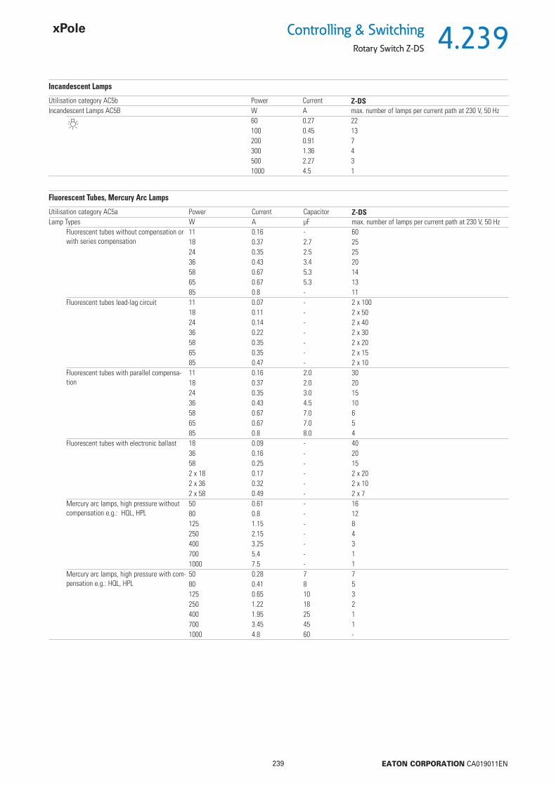
4.239
239 EATON CORPORATION CA019011EN
Controlling & SwitchingRotary Switch Z-DS
Incandescent Lamps
Utilisation category AC5b Power Current Z-DSIncandescent Lamps AC5B W A max. number of lamps per current path at 230 V, 50 Hz
60 0.27 22100 0.45 13200 0.91 7300 1.36 4500 2.27 31000 4.5 1
Fluorescent Tubes, Mercury Arc Lamps
Utilisation category AC5a Power Current Capacitor Z-DSLamp Types W A μF max. number of lamps per current path at 230 V, 50 Hz
Fluorescent tubes without compensation or with series compensation
11 0.16 - 6018 0.37 2.7 2524 0.35 2.5 2536 0.43 3.4 2058 0.67 5.3 1465 0.67 5.3 1385 0.8 - 11
Fluorescent tubes lead-lag circuit 11 0.07 - 2 x 10018 0.11 - 2 x 5024 0.14 - 2 x 4036 0.22 - 2 x 3058 0.35 - 2 x 2065 0.35 - 2 x 1585 0.47 - 2 x 10
Fluorescent tubes with parallel compensa-tion
11 0.16 2.0 3018 0.37 2.0 2024 0.35 3.0 1536 0.43 4.5 1058 0.67 7.0 665 0.67 7.0 585 0.8 8.0 4
Fluorescent tubes with electronic ballast 18 0.09 - 4036 0.16 - 2058 0.25 - 152 x 18 0.17 - 2 x 202 x 36 0.32 - 2 x 102 x 58 0.49 - 2 x 7
Mercury arc lamps, high pressure without compensation e.g.: HQL, HPL
50 0.61 - 1680 0.8 - 12125 1.15 - 8250 2.15 - 4400 3.25 - 3700 5.4 - 11000 7.5 - 1
Mercury arc lamps, high pressure with com-pensation e.g.: HQL, HPL
50 0.28 7 780 0.41 8 5125 0.65 10 3250 1.22 18 2400 1.95 25 1700 3.45 45 11000 4.8 60 -

4.240
240 EATON CORPORATION CA019011EN
Controlling & Switching
Rotary Switch Z-DS
Metal Halide Lamps
Power Current Capacitor Z-DSLamp Types W A μF max. number of lamps per current path at 230 V, 50 Hz
Metal halide lamps without compensation e.g. HQI, HPI
35 0.53 - 2270 1 - 12150 1.8 - 6250 3 - 4400 3.5 - 31000 9.5 - 12000 16.5 - -
Metal halide lamps with compensation e.g. HQI, HPI
35 0.25 6 870 0.45 12 4150 0.75 20 2250 1.5 33 1400 2.1 35 11000 5.8 95 -2000 11.5 148 -
Transformers for low-voltage halogen lamps 20 - - 4050 - - 2075 - - 13100 - - 10150 - - 7200 - - 5300 - - 3
Sodium Vapour Lamps
Power Current Capacitor Z-DSLamp Types W A μF max. number of lamps per current path at 230 V, 50 Hz
Sodium vapour lamps low-pressure without compensation
35 1.5 - 755 1.5 - 790 2.4 - 4135 3.5 - 3150 3.3 - 3180 3.3 - 3200 3.3 - 3
Sodium vapour lamps low-pressure with compensation
35 0.31 20 355 0.42 20 290 0.63 30 1135 0.94 45 1150 1 40 1180 1.16 40 1200 1.32 25 1
Sodium vapour lamps high-pressure without compensation
150 1.8 - 5250 3 - 4330 3.7 - 3400 4.7 - 21000 10.3 - 1
Sodium vapour lamps high pressure with compensation
150 0.83 20 2250 1.5 33 2330 2 40 1400 2.4 48 11000 6.3 106 -

4.241
241 EATON CORPORATION CA019011EN
Controlling & SwitchingRotary Switch Z-DS
Connection diagram
Z-DSA1-01 Z-DSA2-01 Z-DSA2-01-SL Z-DSU1-102 Z-DSU1-H0A
Z-DSU1-T0N Z-DSU2-102 Z-DSU2-H0A Z-DSU3-102 Z-DSU2-12
Z-DSV-LL Z-DSV-LLLN Z-DSV-LN Z-DSAM1-0123
Dimensions (mm)

4.242
242 EATON CORPORATION CA019011EN
Controlling & Switching
Installation Relays Z-R.
Z-R30/16-10
Installation Relays Type Z-R
Control Voltage Function TypeDesignation
Article No. Units perpackage
sg01418_r
• with manual operation and LED• 16 A 240 V AC AC1
230-240 V, 50/60 Hz 1NO Z-R230/16-10 ICS-R16A230B100 2 / 120230-240 V, 50/60 Hz 2NO Z-R230/16-20 ICS-R16A230B200 2 / 120230-240 V, 50/60 Hz 1NC Z-R230/16-01 ICS-R16A230B010 2 / 120230-240 V, 50/60 Hz 1NO + 1NC Z-R230/16-11 ICS-R16A230B110 2 / 12024 V, 50/60 Hz 1NO Z-R24/16-10 ICS-R16A024B100 2 / 12024 V, 50/60 Hz 2NO Z-R24/16-20 ICS-R16A024B200 2 / 12024 V, 50/60 Hz 1NC Z-R24/16-01 ICS-R16A024B010 2 / 12024 V, 50/60 Hz 1NO + 1NC Z-R24/16-11 ICS-R16A024B110 2 / 12024 V DC 1NO Z-R23/16-10 ICS-R16D024B100 2 / 12024 V DC 2NO Z-R23/16-20 ICS-R16D024B200 2 / 12024 V DC 1NC Z-R23/16-01 ICS-R16D024B010 2 / 12024 V DC 1NO + 1NC Z-R23/16-11 ICS-R16D024B110 2 / 120
Accessories Spacer 0.5MU Z-DST 248949 10
Description TypeDesignation
Article No. Units perpackage

4.243
243 EATON CORPORATION CA019011EN
Controlling & SwitchingInstallation Relays Z-R.
Description Installation Relays Z-R
Installation relays Z-R are suitable for switching 1-phase consumers up to 16 A. These devices for universal use in building installations and systems permit implementation of the following applications and control functions:• Switching lighting systems and electrical heating systems• Switching ventilation and air conditioning systems, fans• Switching heat pumps• Switching electrically controlled roller doors/gates, and blinds • Switching incandescent lamps and gas discharge lampsThe installation relays of series Z-R meet the requirements of standards EN/IEC 60947.
EN/IEC 60947 deals with „Electromagnetic contactors in electrical system manufacturing“.
Security:• Manual operation for testing purposes • All terminals - coil and contacts - equipped with guide for secure terminal connection. Misplacement of wires impossible.• Main contacts can be connected to standard pin busbar• Made of hardly fl ammable materials and plastics free from chlorine and halogens• Finger and hand touch safe according to VBG4
Advantages:• Low power loss• No humming• Optical operating status display by means of LED• Low switching noise• Easy to connect thanks to large terminals supplied open• Simple snap-on fastening on 35 mm DIN rail• High degree of fl exibility thanks to a variety of contact confi gurations• Easy access for coil feed connection
Connection diagrams1MU1 NO 2 NO 1 NO / 1 NC 1 NC
Versionwith manualoperation and LED
Dimensions (mm)
Permitted installation positionsmax 30°
Packing densitySpacers recommended! (Z-DST)
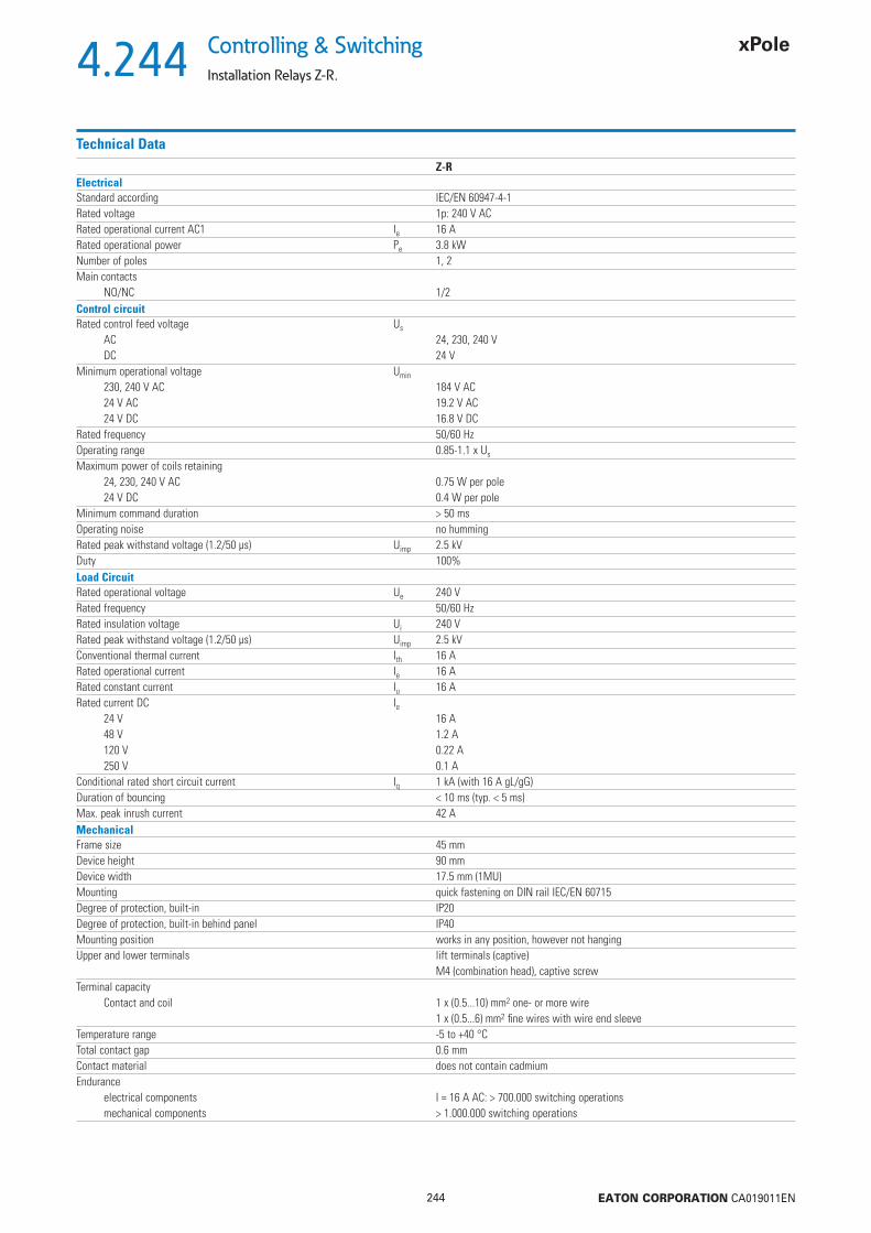
4.244
244 EATON CORPORATION CA019011EN
Controlling & Switching
Installation Relays Z-R.
Technical DataZ-R
ElectricalStandard according IEC/EN 60947-4-1Rated voltage 1p: 240 V ACRated operational current AC1 Ie 16 ARated operational power Pe 3.8 kWNumber of poles 1, 2Main contacts
NO/NC 1/2Control circuitRated control feed voltage Us
AC 24, 230, 240 VDC 24 V
Minimum operational voltage Umin
230, 240 V AC 184 V AC24 V AC 19.2 V AC24 V DC 16.8 V DC
Rated frequency 50/60 HzOperating range 0.85-1.1 x Us
Maximum power of coils retaining24, 230, 240 V AC 0.75 W per pole24 V DC 0.4 W per pole
Minimum command duration > 50 msOperating noise no hummingRated peak withstand voltage (1.2/50 μs) Uimp 2.5 kVDuty 100%Load CircuitRated operational voltage Ue 240 VRated frequency 50/60 HzRated insulation voltage Ui 240 VRated peak withstand voltage (1.2/50 μs) Uimp 2.5 kVConventional thermal current Ith 16 ARated operational current Ie 16 ARated constant current Iu 16 ARated current DC Ie
24 V 16 A48 V 1.2 A120 V 0.22 A250 V 0.1 A
Conditional rated short circuit current Iq 1 kA (with 16 A gL/gG)Duration of bouncing < 10 ms (typ. < 5 ms)Max. peak inrush current 42 AMechanicalFrame size 45 mmDevice height 90 mmDevice width 17.5 mm (1MU)Mounting quick fastening on DIN rail IEC/EN 60715Degree of protection, built-in IP20Degree of protection, built-in behind panel IP40Mounting position works in any position, however not hangingUpper and lower terminals lift terminals (captive)
M4 (combination head), captive screwTerminal capacity
Contact and coil 1 x (0.5...10) mm2 one- or more wire1 x (0.5...6) mm2 fi ne wires with wire end sleeve
Temperature range -5 to +40 °CTotal contact gap 0.6 mmContact material does not contain cadmiumEndurance
electrical components I = 16 A AC: > 700.000 switching operationsmechanical components > 1.000.000 switching operations
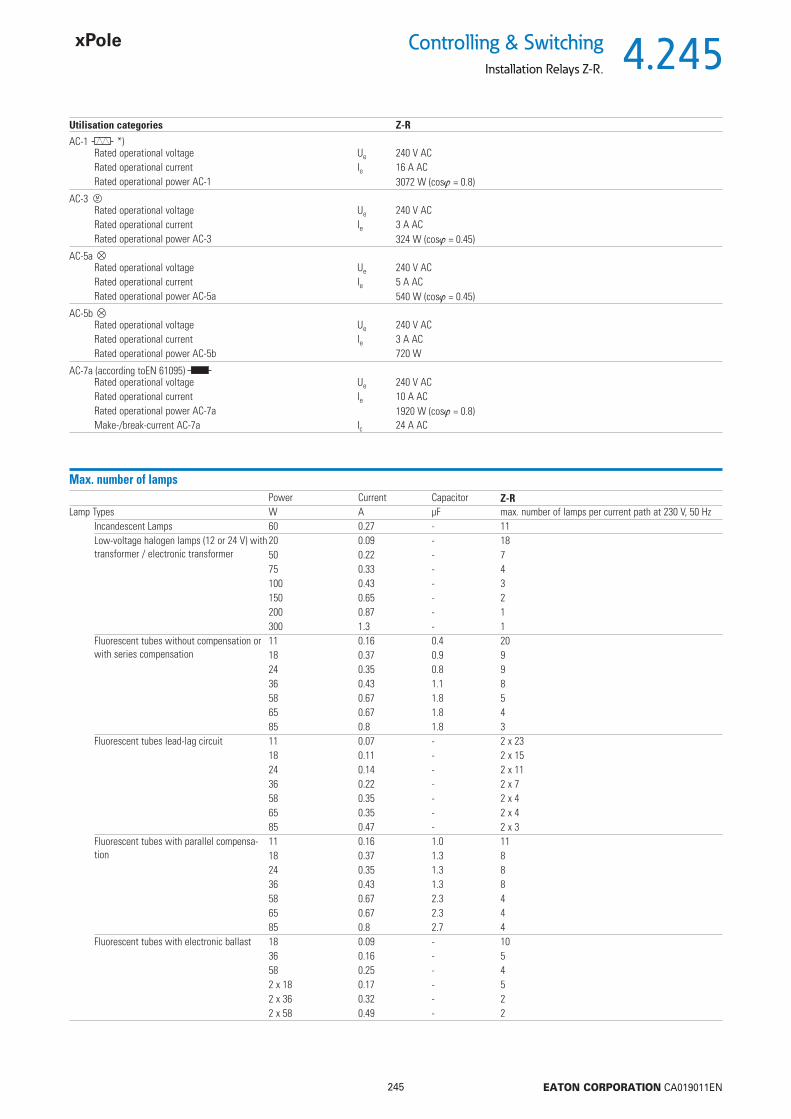
4.245
245 EATON CORPORATION CA019011EN
Controlling & SwitchingInstallation Relays Z-R.
Utilisation categories Z-R
AC-1 *)Rated operational voltage Ue 240 V ACRated operational current Ie 16 A ACRated operational power AC-1 3072 W (cos = 0.8)
AC-3 Rated operational voltage Ue 240 V ACRated operational current Ie 3 A ACRated operational power AC-3 324 W (cos = 0.45)
AC-5a Rated operational voltage Ue 240 V ACRated operational current Ie 5 A ACRated operational power AC-5a 540 W (cos = 0.45)
AC-5b Rated operational voltage Ue 240 V ACRated operational current Ie 3 A ACRated operational power AC-5b 720 W
AC-7a (according toEN 61095) Rated operational voltage Ue 240 V ACRated operational current Ie 10 A ACRated operational power AC-7a 1920 W (cos = 0.8)Make-/break-current AC-7a Ic 24 A AC
Max. number of lampsPower Current Capacitor Z-R
Lamp Types W A μF max. number of lamps per current path at 230 V, 50 HzIncandescent Lamps 60 0.27 - 11Low-voltage halogen lamps (12 or 24 V) with transformer / electronic transformer
20 0.09 - 1850 0.22 - 775 0.33 - 4100 0.43 - 3150 0.65 - 2200 0.87 - 1300 1.3 - 1
Fluorescent tubes without compensation or with series compensation
11 0.16 0.4 2018 0.37 0.9 924 0.35 0.8 936 0.43 1.1 858 0.67 1.8 565 0.67 1.8 485 0.8 1.8 3
Fluorescent tubes lead-lag circuit 11 0.07 - 2 x 2318 0.11 - 2 x 1524 0.14 - 2 x 1136 0.22 - 2 x 758 0.35 - 2 x 465 0.35 - 2 x 485 0.47 - 2 x 3
Fluorescent tubes with parallel compensa-tion
11 0.16 1.0 1118 0.37 1.3 824 0.35 1.3 836 0.43 1.3 858 0.67 2.3 465 0.67 2.3 485 0.8 2.7 4
Fluorescent tubes with electronic ballast 18 0.09 - 1036 0.16 - 558 0.25 - 42 x 18 0.17 - 52 x 36 0.32 - 22 x 58 0.49 - 2

4.246
246 EATON CORPORATION CA019011EN
Controlling & Switching
Installation Relays Z-R.
LED Lamps
Type of lamps Z-RLED Lamps.Pay attention on the inrush current of the ballast and cos of the lamp
max. permissible inrush current of installation relay [A]
42 A
Max. Inrush current installation relay [A]= max. number of lamps per pole
Inrush current lamp [A]

4.247
247 EATON CORPORATION CA019011EN
Controlling & SwitchingInstallation Relays Z-TN
Z-TN230/SO
Installation Relays Type Z-TN
Control Voltage Function MU TypeDesignation
Article No. Units perpackage
SG59711 230 V, 50 Hz 2NO 1 Z-TN230/SS 265574 2 / 120230 V, 50 Hz 3NO 2 Z-TN230/3S 265576 1 / 60230 V, 50 Hz 4NO 2 Z-TN230/4S 265579 1 / 60230 V, 50 Hz 1NO+1NC 1 Z-TN230/1S1O 267975 2 / 120230 V, 50 Hz 2NO+2NC 2 Z-TN230/2S2O 103168 1 / 6024 V, 50 Hz 2NO 1 Z-TN24/SS 267976 2 / 12024 V, 50 Hz 3NO 2 Z-TN24/3S 267977 1 / 6024 V, 50 Hz 4NO 2 Z-TN24/4S 267978 1 / 6024 V, 50 Hz 1NO+1NC 1 Z-TN24/1S1O 267979 2 / 120
• with manual pre-selection of functions - permanently ON / AUTOM / OFF• 20 A 250 V AC
Z-TN230/3S
SG60111
Accessories Spacer 0.5MU Z-DST 248949 10
Description TypeDesignation
Article No. Units perpackage

4.248
248 EATON CORPORATION CA019011EN
Controlling & Switching
Installation Relays Z-TN
Description Installation Relays Z-TN
Installation relays Z-TN are suitable for switching 1-phase or 3-phases consumers up to 20 A. These devices for universal use in building installations and systems permit imple-mentation of the following applications and control functions: • Switching lighting systems and electrical heating systems• Switching ventilation and air conditioning systems, fans• Switching heat pumps• Switching electrically controlled roller doors/gates, and blinds • Switching incandescent lamps and gas discharge lampsThe installation relays of series Z-TN meet the requirements of standards EN/IEC 60947 and EN/IEC 1095.
EN/IEC 1095 deals with „Electromechanical contactors for household and similar purposes.“ Compliance with this standard means meeting very high demands in terms of safety for humans and property.
EN/IEC 60947 deals with „Electromagnetic contactors in electrical system manufacturing“.
Security:• Manual operation • All terminals - coil and contacts - equipped with guide for secure terminal connection. Misplacement of wires impossible.• Main contacts can be connected to standard pin busbar• Made of hardly fl ammable materials and plastics free from chlorine and halogens• Finger and hand touch safe according to VBG4
Advantages:• Low switching noise• Easy to connect thanks to large terminals supplied open• Simple snap-on fastening on 35 mm DIN rail• High degree of fl exibility thanks to a variety of contact confi gurations• Easy access for coil feed connection• Version with mechanical pre-selection of functions ON/AUTO/OFF
ON/permanently ON: Contact permanently ON until a control pulse is switched on and OFF again. Then, the relay reverts to the AUT position.AUT/AUTOMATIC: Standard relay function by control voltage at the coil.OFF/permanently OFF: Contacts permanently OFF, independently of the control voltage at the coil.
• Only in AC
Connection diagrams1MU 2MU“SS” “SO” “2S2O”2 NO 1 NO / 1 NC 2 NO / 2 NC
2MU
Versionswith mech.pre-selection
“3S” “4S”3 NO 4 NO
Dimensions (mm)1MU 2MU
Permitted installation positionsmax 30°
Packing densitySpacers recommended! (Z-DST)

4.249
249 EATON CORPORATION CA019011EN
Controlling & SwitchingInstallation Relays Z-TN
Technical DataZ-TN
ElectricalStandard according IEC/EN 60947Rated voltage 250 V, 240/415 V ACRated current 250 V AC 20 ARated current AC1 Ie 20 A Rated operational power Pe 4.6 kW 415 VNumber of poles 1 to 4Main contacts
NO/NC 1/2 (1MU), 3/4 (2MU)EMC-Environment BControl circuitRated control feed voltage Us
AC 8, 12, 24, 48, 110, 230, 240 VDC 8, 12, 24, 110 V
Rated frequency 50 HzOperating range 0.85-1.1 x Us
Maximum power of coilspick-up 10-13 VA, 6-8 Wretaining 3.4-4.0 VA, 2.0-2.4 W
Minimum command duration > 50 msOperating noise low noiseRated peak withstand voltage (1.2/50 μs) Uimp 2 kVDuty 100%Load CircuitRated operational voltage Ue
1p, 2p 250 VAC3p, 4p 240/415 VAC
Minimum operational voltage Umin 24 V AC/DC (Us 8-110 V)Rated insulation voltage Ui 500 VRated peak withstand voltage (1.2/50 μs) Uimp 4 kVConventional thermal current Ith 20 A ACRated operational current Ie 20 A ACRated constant current Iu 20 A ACRated current DC Ie
24 V 16 A48 V 12.5 A230 V 1 A
Conditional rated short circuit current Iq 10 kA (with 20 A gL/gG)Duration of bouncing < 10 ms (typ. < 5 ms)MechanicalFrame size 45 mmDevice height 90 mmDevice width 17.5 mm (1MU)Mounting quick fastening on DIN rail IEC/EN 60715Degree of protection, built-in IP20Mounting position works in any position, however not hangingUpper and lower terminals lift terminals (captive)Terminal capacity
Contact and coil 0.5 - 10 mm2 one- or more wire0.5 - 6 mm2 fi ne wires with wire end sleeve
Temperature range -20 to +45 °CTotal contact gap > 5 mm / independent contactsContact material does not contain cadmiumEndurance
electrical components 40x103 switching operationsmechanical components 1x10⁶ switching operations
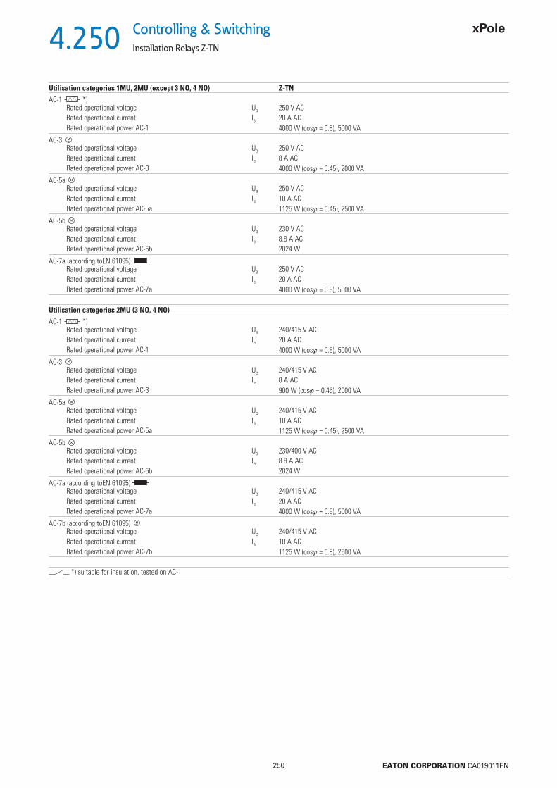
4.250
250 EATON CORPORATION CA019011EN
Controlling & Switching
Installation Relays Z-TN
Utilisation categories 1MU, 2MU (except 3 NO, 4 NO) Z-TN
AC-1 *)Rated operational voltage Ue 250 V ACRated operational current Ie 20 A ACRated operational power AC-1 4000 W (cos = 0.8), 5000 VA
AC-3 Rated operational voltage Ue 250 V ACRated operational current Ie 8 A ACRated operational power AC-3 4000 W (cos = 0.45), 2000 VA
AC-5a Rated operational voltage Ue 250 V ACRated operational current Ie 10 A ACRated operational power AC-5a 1125 W (cos = 0.45), 2500 VA
AC-5b Rated operational voltage Ue 230 V ACRated operational current Ie 8.8 A ACRated operational power AC-5b 2024 W
AC-7a (according toEN 61095) Rated operational voltage Ue 250 V ACRated operational current Ie 20 A ACRated operational power AC-7a 4000 W (cos = 0.8), 5000 VA
Utilisation categories 2MU (3 NO, 4 NO)
AC-1 *)Rated operational voltage Ue 240/415 V ACRated operational current Ie 20 A ACRated operational power AC-1 4000 W (cos = 0.8), 5000 VA
AC-3 Rated operational voltage Ue 240/415 V ACRated operational current Ie 8 A ACRated operational power AC-3 900 W (cos = 0.45), 2000 VA
AC-5a Rated operational voltage Ue 240/415 V ACRated operational current Ie 10 A ACRated operational power AC-5a 1125 W (cos = 0.45), 2500 VA
AC-5b Rated operational voltage Ue 230/400 V ACRated operational current Ie 8.8 A ACRated operational power AC-5b 2024 W
AC-7a (according toEN 61095) Rated operational voltage Ue 240/415 V ACRated operational current Ie 20 A ACRated operational power AC-7a 4000 W (cos = 0.8), 5000 VA
AC-7b (according toEN 61095) Rated operational voltage Ue 240/415 V ACRated operational current Ie 10 A ACRated operational power AC-7b 1125 W (cos = 0.8), 2500 VA
*) suitable for insulation, tested on AC-1

4.251
251 EATON CORPORATION CA019011EN
Controlling & SwitchingInstallation Relays Z-TN
Max. number of lampsPower Current Capacitor Z-TN
Lamp Types W A μF max. number of lamps per current path at 230 V, 50 HzIncandescent Lamps 60 0.27 - 33Low-voltage halogen lamps (12 or 24 V) with transformer / electronic transformer
20 0.09 - 5550 0.22 - 2275 0.33 - 14100 0.43 - 11150 0.65 - 7200 0.87 - 5300 1.3 - 3
Fluorescent tubes without compensation or with series compensation
11 0.16 1.3 6218 0.37 2.7 2724 0.35 2.5 2736 0.43 3.4 2458 0.67 5.3 1565 0.67 5.3 1485 0.8 5.3 12
Fluorescent tubes lead-lag circuit 11 0.07 - 2 x 7118 0.11 - 2 x 4524 0.14 - 2 x 3536 0.22 - 2 x 2258 0.35 - 2 x 1465 0.35 - 2 x 1485 0.47 - 2 x 10
Fluorescent tubes with parallel compensa-tion
11 0.16 3.0 3418 0.37 4.0 2624 0.35 4.0 2636 0.43 4.0 2658 0.67 7.0 1465 0.67 7.0 1485 0.8 8.0 13
Fluorescent tubes with electronic ballast 18 0.09 - 3236 0.16 - 1658 0.25 - 122 x 18 0.17 - 162 x 36 0.32 - 82 x 58 0.49 - 6

4.252
252 EATON CORPORATION CA019011EN
Controlling & Switching
Installation Contactors CR
Installation Contactors, 20A
Uc Rating Function TypeDesignation
Article No. Units perpackage
sg05617_r 24 V AC/DC 20 A 1NO + 1NC CR2011024 135171 124 V AC/DC 20 A 2NO CR2020024 135177 124 V AC/DC 20 A 2NC CR2002024 176469 112 V AC/DC 20 A 1NO + 1NC CR2011012 193906 112 V AC/DC 20 A 2NO CR2020012 135175 112 V AC/DC 20 A 2NC CR2002012 193907 18 V AC/DC 20 A 1NO + 1NC CR2011008 193909 18 V AC/DC 20 A 2NO CR2020008 193908 1
Accessories Spacer 0.5MU Z-DST 248949 10
Description TypeDesignation
Article No. Units perpackage

4.253
253 EATON CORPORATION CA019011EN
Controlling & SwitchingInstallation Contactors CR
Description Installation Contactors CR
Contactors are frequently applied for switching of lamp loads, fans or pumps in both utility as well as industrial areas. All contactors with AC/DC coils ensure silent operation which is further enhanced by a low power consumption. Optimal contacts and low heat dissipation guarantee a long lifetime of the contactor.
Technical characteristics:• Designed according to IEC 60947-4-1 and IEC 61095 standards• Suitable for applications in general control, heating & lighting applications• Available in 20 A rating with 2-pole contacts• Coil voltages: 8 V AC/DC, 12 V AC/DC, 24 V AC/DC• DIN modular profi le• Spacers available to extend lifetime (it is recommended to use 1 spacer between every 2 contactors installed)
Advantages:• Low inrush power for all AC/DC types• Availability of combined AC/DC type contactors ensure silent operation• Contactors of AC/DC coil type are operable on both AC and DC voltage• All combined AC/DC type versions are equipped with surge protection on the operating coil• Equipped with contact indication• Optimal quality of contacts and low heat dissipation ensure a long life time
Connection diagrams2NO 1NO + 1NC 2NC
Dimensions (mm)CR
Permitted installation positions Packing densitySpacers recommended! (Z-DST)

4.254
254 EATON CORPORATION CA019011EN
Controlling & Switching
Installation Contactors CR
Technical DataCR
GeneralStandards IEC 60947-4-1, IEC 61095Nominal operating voltage Ue 230 VMechanical endurance 3,000,000 switching cyclesProtection class (according to DIN 40 050, IEC 529) IP20Permissible ambient temperature -5 °C up to 55 °CStorage temperature -30 °C up to +80 °CContact ratingRated insulation voltage Ui 230 VFrequency 50 - 60 HzRated impulse withstand voltage Uimp 4 kVRated thermal current Ith 20 AAC1 / AC7a Rated operational current Ie 20 AAC1 / AC7a Operational power rating at Ue = 230 VAC Pmax 4 kWAC3 / AC7b Operational power rating at Ue = 230 VAC Pmax NO: 1.3 kW; NC: 0.75 kWDC1 (L/R 1 ms) Rated thermal current
1-pole:at Ue = 24 V DC 20 Aat Ue = 110 V DC 6 Aat Ue = 220 V DC 0,6 A2-poles in series:at Ue = 24 V DC 20 Aat Ue = 110 V DC 10 Aat Ue = 220 V DC 6 A
Electrical enduranceAC1 / AC7a Application 200,000 maximum operating cyclesAC3 / AC7b Application 300,000 maximum operating cyclesAC-1/AC-3/AC-5b/AC-6b/AC-15 600 maximum operating cycles per hourPower dissipation per contact at In 1.7 WOperating coilCoil inrush power (for all voltage ratings) 2.5 WCoil consumption (for all voltage ratings) 2.5 WClosing delay 15 – 45 msOpening delay 20 − 50 msRange of control voltage Uc 85 up to 110%Kind of voltage AC / DCFrequency (AC) 50/60 HzDimensionsWidth 17.5 mmHeight 85 mmDepth 65 mmTerminals for mainTerminal capacity - fi ne stranded wire 1 to 6 mm2
Terminal capacity - solid wire 1 to 10 mm2
Terminal screw size M3,5Terminal screw head type (Pozidrive) PZ Size 1Maximum torque 1.2 NmTerminals for operating coilsTerminal capacity - fi ne stranded wire 1 to 2.5 mm2
Terminal capacity - solid wire 1 to 2.5 mm2
Terminal screw size M3,5Terminal screw head type (Pozidrive) PZ Size 1Maximum torque 0.6 Nm

4.255
255 EATON CORPORATION CA019011EN
Controlling & SwitchingInstallation Contactors CR
Fluorescent Tubes, Mercury Arc Lamps
Power Current Capacitor CRLamp Types W A μF max. number of lamps per current path at 230 V, 50 Hz
Incandescent lamps and halogen lamps 15 0.07 − 13025 0.11 − 8040 0.18 − 5060 0.26 − 3375 0.33 − 26100 0.44 − 20150 0.65 − 13200 0.87 − 10300 1.30 − 6500 2.17 − 31000 4.35 – 1
Energy saving lamps 3 0.03 − 505 0.04 − 457 0.055 − 408 0.065 − 359 0.075 − 3010 0.08 − 3011 0.09 − 3012 0.1 − 2514 0.11 − 2515 0.12 − 2016 0.13 − 2018 0.145 − 1820 0.16 − 1721 0.17 − 1523 0.185 − 1524 0.195 − 1530 0.16 − 15
Compact fl uorescent lamps - series correction
10 0.19 1.4 5013 0.18 1.4 5018 0.23 1.7 4026 0.33 2.5 3018 0.38 2.7 2524 0.35 2.7 2536 0.44 3.4 20
Compact fl uorescent lamps - parallel correction
5 0.18 2.2 137 0.18 2.1 149 0.17 2.0 1510 0.19 2.2 1311 0.16 1.7 1713 0.18 1.8 1618 0.23 2.3 1326 0.33 3.3 918 0.38 4.2 724 0.35 3.6 836 0.44 4.4 6
Compact fl uorescent lamps with electronic control gear (ECG)
5 0.05 − 457 0.05 − 459 0.07 − 3210 0.07 − 3211 0.07 − 3213 0.07 − 3218 0.22 − 1024 0.22 − 1026 0.22 − 1032 0.22 − 1036 0.22 − 1040 0.22 − 1042 0.22 − 1055 0.28 − 857 0.28 − 870 0.35 − 680 0.41 − 5120 0.58 − 4
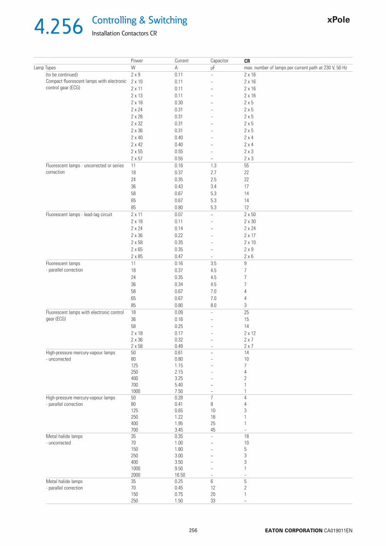
4.256
256 EATON CORPORATION CA019011EN
Controlling & Switching
Installation Contactors CR
Power Current Capacitor CRLamp Types W A μF max. number of lamps per current path at 230 V, 50 Hz
(to be continued)Compact fl uorescent lamps with electronic control gear (ECG)
2 x 9 0.11 − 2 x 162 x 10 0.11 − 2 x 162 x 11 0.11 − 2 x 162 x 13 0.11 − 2 x 162 x 18 0.30 − 2 x 52 x 24 0.31 − 2 x 52 x 26 0.31 − 2 x 52 x 32 0.31 − 2 x 52 x 36 0.31 − 2 x 52 x 40 0.40 − 2 x 42 x 42 0.40 − 2 x 42 x 55 0.55 − 2 x 32 x 57 0.55 − 2 x 3
Fluorescent lamps - uncorrected or seriescorrection
11 0.16 1.3 5518 0.37 2.7 2224 0.35 2.5 2236 0.43 3.4 1758 0.67 5.3 1465 0.67 5.3 1485 0.80 5.3 12
Fluorescent lamps - lead-lag circuit 2 x 11 0.07 − 2 x 502 x 18 0.11 − 2 x 302 x 24 0.14 − 2 x 242 x 36 0.22 − 2 x 172 x 58 0.35 − 2 x 102 x 65 0.35 − 2 x 92 x 85 0.47 − 2 x 6
Fluorescent lamps - parallel correction
11 0.16 3.5 918 0.37 4.5 724 0.35 4.5 736 0.34 4.5 758 0.67 7.0 465 0.67 7.0 485 0.80 8.0 3
Fluorescent lamps with electronic control gear (ECG)
18 0.09 − 2536 0.16 − 1558 0.25 − 142 x 18 0.17 − 2 x 122 x 36 0.32 − 2 x 72 x 58 0.49 − 2 x 7
High-pressure mercury-vapour lamps- uncorrected
50 0.61 − 1480 0.80 − 10125 1.15 − 7250 2.15 − 4400 3.25 − 2700 5.40 − 11000 7.50 − 1
High-pressure mercury-vapour lamps- parallel correction
50 0.28 7 480 0.41 8 4125 0.65 10 3250 1.22 18 1400 1.95 25 1700 3.45 45 −
Metal halide lamps - uncorrected
35 0.35 − 1870 1.00 − 10150 1.80 − 5250 3.00 − 3400 3.50 − 31000 9.50 − 12000 16.50 − −
Metal halide lamps - parallel correction
35 0.25 6 570 0.45 12 2150 0.75 20 1250 1.50 33 −
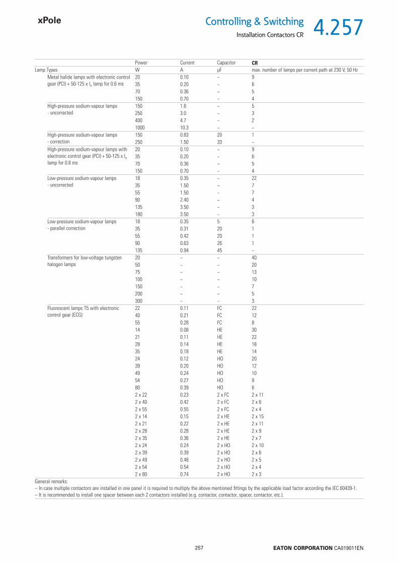
4.257
257 EATON CORPORATION CA019011EN
Controlling & SwitchingInstallation Contactors CR
Power Current Capacitor CRLamp Types W A μF max. number of lamps per current path at 230 V, 50 Hz
Metal halide lamps with electronic control gear (PCI) + 50-125 x In lamp for 0.6 ms
20 0.10 − 935 0.20 − 670 0.36 − 5150 0.70 − 4
High-pressure sodium-vapour lamps - uncorrected
150 1.8 − 5250 3.0 − 3400 4.7 − 21000 10.3 − −
High-pressure sodium-vapour lamps - correction
150 0.83 20 1250 1.50 33 −
High-pressure sodium-vapour lamps with electronic control gear (PCI) + 50-125 x In lamp for 0.6 ms
20 0.10 − 935 0.20 − 670 0.36 − 5150 0.70 − 4
Low-pressure sodium-vapour lamps - uncorrected
18 0.35 − 2235 1.50 − 755 1.50 − 790 2.40 − 4135 3.50 − 3180 3.50 − 3
Low-pressure sodium-vapour lamps- parallel correction
18 0.35 5 635 0.31 20 155 0.42 20 190 0.63 26 1135 0.94 45 −
Transformers for low-voltage tungsten halogen lamps
20 − − 4050 − − 2075 − − 13100 − − 10150 − − 7200 − − 5300 − − 3
Fluorescent lamps T5 with electronic control gear (ECG)
22 0.11 FC 2240 0.21 FC 1255 0.28 FC 814 0.08 HE 3021 0.11 HE 2228 0.14 HE 1835 0.18 HE 1424 0.12 HO 2039 0.20 HO 1249 0.24 HO 1054 0.27 HO 980 0.39 HO 62 x 22 0.23 2 x FC 2 x 112 x 40 0.42 2 x FC 2 x 62 x 55 0.55 2 x FC 2 x 42 x 14 0.15 2 x HE 2 x 152 x 21 0.22 2 x HE 2 x 112 x 28 0.28 2 x HE 2 x 92 x 35 0.36 2 x HE 2 x 72 x 24 0.24 2 x HO 2 x 102 x 39 0.39 2 x HO 2 x 62 x 49 0.48 2 x HO 2 x 52 x 54 0.54 2 x HO 2 x 42 x 80 0.74 2 x HO 2 x 3
General remarks:– In case multiple contactors are installed in one panel it is required to multiply the above mentioned fi ttings by the applicable load factor according the IEC 60439-1.– It is recommended to install one spacer between each 2 contactors installed (e.g. contactor, contactor, spacer, contactor, etc.).

4.258
258 EATON CORPORATION CA019011EN
Controlling & Switching
Installation Contactors Z-SCH, CMUC
CMUC230/25-40
Installation Contactors CMUC
SG28812 230 V AC/DC 25 A 4NO CMUC230/25-40 137309 1 / 60230 V AC/DC 25 A 4NC CMUC230/25-04 137405 1 / 60230 V AC/DC 25 A 3NO+1NC CMUC230/25-31 137401 1 / 60230 V AC/DC 25 A 2NO+2NC CMUC230/25-22 137403 1 / 6024 V AC/DC 25 A 4NO CMUC24/25-40 137308 1 / 6024 V AC/DC 25 A 4NC CMUC24/25-04 137404 1 / 6024 V AC/DC 25 A 3NO+1NC CMUC24/25-31 137400 1 / 6024 V AC/DC 25 A 2NO+2NC CMUC24/25-22 137402 1 / 60
• Universal Control Voltage Us AC/DC
Installation Contactors Z-SCH
Us In AC1 Function TypeDesignation
Article No. Units perpackage
230 V AC 25 A 2NO Z-SCH230/1/25-20 120853 2 / 120230 V AC 25 A 1NO+1NC Z-SCH230/1/25-11 193886 2 / 120230 V AC 25 A 2NC Z-SCH230/1/25-02 193887 2 / 12024 V AC 25 A 2NO Z-SCH24/1/25-20 193885 2 / 12024 V AC 25 A 1NO+1NC Z-SCH24/1/25-11 193888 2 / 12024 V AC 25 A 2NC Z-SCH24/1/25-02 193984 2 / 120230 V AC 25 A 4NO Z-SCH230/25-40 248847 1 / 60230 V AC 25 A 4NC Z-SCH230/25-04 248848 1 / 60230 V AC 25 A 3NO+1NC Z-SCH230/25-31 248846 1 / 60230 V AC 25 A 2NO+2NC Z-SCH230/25-22 248849 1 / 6024 V AC 25 A 4NO Z-SCH24/25-40 248851 1 / 6024 V AC 25 A 2NO+2NC Z-SCH24/25-22 248850 1 / 60230 V AC 40 A 4NO Z-SCH230/40-40 248852 1 / 40230 V AC 40 A 3NO+1NC Z-SCH230/40-31 248854 1 / 40230 V AC 40 A 2NO+2NC Z-SCH230/40-22 248853 1 / 40230 V AC 40 A 2NO Z-SCH230/40-20 248855 1 / 40230 V AC 63 A 4NO Z-SCH230/63-40 248856 1 / 40230 V AC 63 A 4NC Z-SCH230/63-04 285735 1 / 40230 V AC 63 A 3NO+1NC Z-SCH230/63-31 248858 1 / 40230 V AC 63 A 2NO+2NC Z-SCH230/63-22 248857 1 / 40230 V AC 63 A 2NO Z-SCH230/63-20 248859 1 / 40
Z-SC
Accessories suitable for Z-SCH / CMUCSG84311 Sealing cover Z-SCHAK-2TE 248860 10
Sealing cover Z-SCHAK-3TE 248861 10Auxiliary Switch 1NO+1NC *) Z-SC 248862 3Spacer 0.5MU Z-DST 248949 10Suppressor RC-Combination 12-250 VAC Z-RC/230 101428 2 / 120
*) NOT suitable for Z-SCH.../1/...- and CMUC types
Description TypeDesignation
Article No. Units perpackage
Z-SCH230/25-40
SG84611
Z-SCH230/63-40
SG84711
Z-SCH230/1/25-20
SG84511
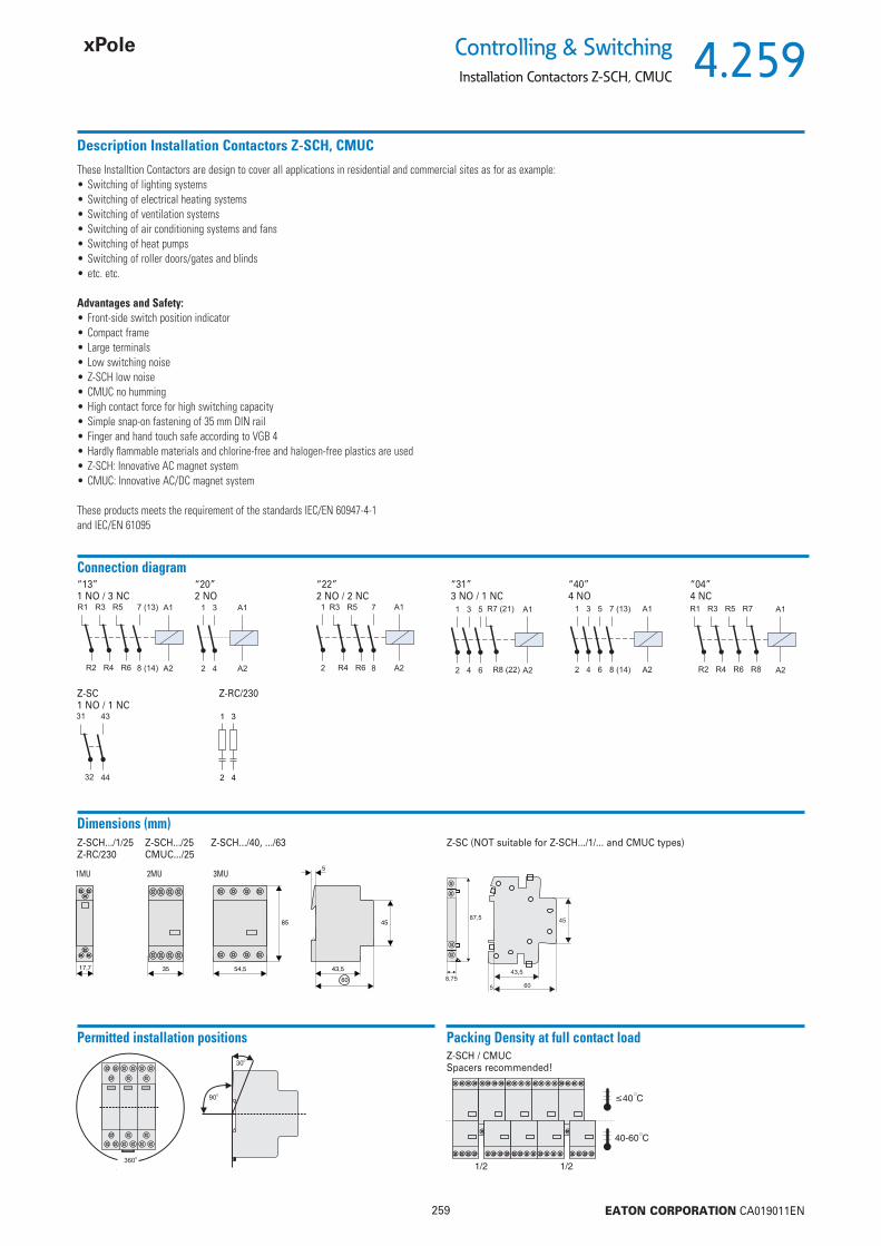
4.259
259 EATON CORPORATION CA019011EN
Controlling & SwitchingInstallation Contactors Z-SCH, CMUC
Description Installation Contactors Z-SCH, CMUC
These Installtion Contactors are design to cover all applications in residential and commercial sites as for as example:• Switching of lighting systems• Switching of electrical heating systems• Switching of ventilation systems• Switching of air conditioning systems and fans• Switching of heat pumps• Switching of roller doors/gates and blinds • etc. etc.
Advantages and Safety:• Front-side switch position indicator• Compact frame• Large terminals• Low switching noise• Z-SCH low noise• CMUC no humming• High contact force for high switching capacity• Simple snap-on fastening of 35 mm DIN rail• Finger and hand touch safe according to VGB 4• Hardly fl ammable materials and chlorine-free and halogen-free plastics are used• Z-SCH: Innovative AC magnet system• CMUC: Innovative AC/DC magnet system
These products meets the requirement of the standards IEC/EN 60947-4-1 and IEC/EN 61095
Connection diagram“13” “20” “22”1 NO / 3 NC 2 NO 2 NO / 2 NC
Z-SC1 NO / 1 NC
“31” “40” “04”3 NO / 1 NC 4 NO 4 NC
Permitted installation positions Packing Density at full contact loadZ-SCH / CMUCSpacers recommended!
Dimensions (mm)Z-SCH.../1/25 Z-SCH.../25 Z-SCH.../40, .../63Z-RC/230 CMUC.../25
Z-SC (NOT suitable for Z-SCH.../1/... and CMUC types)
1MU 2MU 3MU
Z-RC/230
1
2
3
4

4.260
260 EATON CORPORATION CA019011EN
Controlling & Switching
Installation Contactors Z-SCH, CMUC
Technical DataZ-SCH/25/.., CMUC.../25/ Z-SCH/40/.. Z-SCH/63/.. Z-SC
Data according to IEC 61095, EN 61095, VDE 0660, IEC 60947-4-1, EN 60947-4-1, VDEUtilisation category AC1 (e.g. heating system)
Rated operational current (= Ith) Inopen at 60 °C 25 A 40 A 63 A -Service life of switching element 0.1 S x 106 0.1 S x 106 0.1 S x 106 -Rated operational power AC1 220 - 240 V 9.5 kW 16 kW 25 kW -Rated operational power AC1 380 - 415 V 17 kW 27.5 kW 43 kW -Lowest switching power 24 V / 100 mA 24 V / 100 mA 24 V / 100 mA 17 V / 5 mA
Utilisation category AC3 (Switching of 3phase AC motors)Rated operational current In 9 A 27 A 30 A -Service life of switching element 0.15 S x 106 0.15 S x 106 0.15 S x 106 -Rated power of 3phase AC motors 50-60 Hz, 220 V 2.2 kW 7.5 kW 8 kW -Rated power of 3phase AC motors 50-60 Hz, 230-240 V 2.5 kW 8 kW 8.5 kW -Rated power of 3phase AC motors 50-60 Hz, 380-415 V 4 kW 12.5 kW 15 kW -
Utilisation category DC1 (Switching of resistive loads, L/R 15 ms), values for NO contacts1pole 24 V DC 25 A 40 A 63 A -1pole 48 V DC 22 A 25 A 26 A -1pole 60 V DC 18 A 19 A 21 A -1pole 110 V DC 5 A 7 A 8 A -1pole 220 V DC 0.5 A 0.7 A 0.7 A -2pole in series 24 V DC 25 A 40 A 63 A -2pole in series 48 V DC 25 A 40 A 44 A -2pole in series 60 V DC 25 A 33 A 36 A -2pole in series 110 V DC 16 A 17 A 18 A -2pole in series 220 V DC 4 A 5 A 6 A -3pole in series 24 V DC 25 A 40 A 63 A -3pole in series 48 V DC 25 A 40 A 63 A -3pole in series 60 V DC 25 A 40 A 61 A -3pole in series 110 V DC 25 A 31 A 34 A -3pole in series 220 V DC 10 A 15 A 16 A -4pole in series 24 V DC 25 A 40 A 63 A -4pole in series 48 V DC 25 A 40 A 63 A -4pole in series 60 V DC 25 A 40 A 63 A -4pole in series 110 V DC 25 A 40 A 63 A -4pole in series 220 V DC 15 A 20 A 21 A -
Utilisation category DC3 and DC5 (Switching of resistive loads, L/R 15 ms), values for NO contacts1pole 24 V DC 15 A 23 A 25 A -1pole 48 V DC 5 A 10 A 10 A -1pole 60 V DC 4 A 5 A 5 A -1pole 110 V DC 1 A 1.5 A 1.5 A -1pole 220 V DC 0.1 A 0.3 A 0.3 A -2pole in series 24 V DC 25 A 40 A 45 A -2pole in series 48 V DC 17 A 23 A 25 A -2pole in series 60 V DC 13 A 15 A 15 A -2pole in series 110 V DC 5 A 5 A 5 A -2pole in series 220 V DC 0.5 A 1 A 1 A -3pole in series 24 V DC 25 A 40 A 63 A -3pole in series 48 V DC 25 A 40 A 45 A -3pole in series 60 V DC 25 A 30 A 30 A -3pole in series 110 V DC 15 A 15 A 15 A -3pole in series 220 V DC 3 A 4 A 4 A -4pole in series 24 V DC 25 A 40 A 63 A -4pole in series 48 V DC 25 A 40 A 63 A -4pole in series 60 V DC 25 A 40 A 63 A -4pole in series 110 V DC 25 A 40 A 45 A -4pole in series 220 V DC 8 A 10 A 10 A -
Main switching elements (Uimp = 4 kV)Rated insulation voltage Ui 440 V AC 440 V AC 440 V AC 440 V ACRated operational voltage Ue 440 V AC 440 V AC 440 V AC 440 V ACPermissible switching frequency AC1, AC3 z 300 x/h 600 x/h 600 x/h 600 x/hEndurance mechanical components 1 x 10⁶ 1 x 10⁶ 1 x 10⁶ 1 x 10⁶

4.261
261 EATON CORPORATION CA019011EN
Controlling & SwitchingInstallation Contactors Z-SCH, CMUC
Technical Data (continue page)Z-SCH/25/.., CMUC.../25/ Z-SCH/40/.. Z-SCH/63/.. Z-SC
Auxiliary switching elements (Uimp = 4 kV)Rated insulation voltage Ui 440 V AC 440 V AC 440 V AC 440 V ACNominal thermal current = Ith, 40°C 25 A 40 A 63 A 10 ANominal thermal current = Ith, 60°C 25 A 40 A 63 A 6 A
Utilisation category AC15 (Controlling of electromagnetic load)Rated operational current 220-240 V Ie - - - 3 ARated operational current 380-415 V Ie - - - 2 ARated operational current 440 V Ie - - - 1.6 A
Utilisation category DC13 (Controlling of electromagnetic load at DC)Rated operational current per pole 24-60 V Ie - - - 2 ARated operational current per pole 110 V Ie - - - 0.4 ARated operational current per pole 220 V Ie - - - 0.1 A
Trip Coil Power
Z-SCHSwitching on 14 - 18 VA 33 - 45 VA 33 - 45 VA -Holding 4.4 - 8.4 VA 7 VA 7 VA -
1.6 - 3.2 W 2.6 W 2.6 W -
CMUC 3 - 4 W - - -Operating range of trip coils multiple of Ue (-40 to +40°C)
Z-SCHCoil voltage 50 Hz 24, 220 - 240 V 220 - 240 V 220 - 240 V -Coil voltage 60 Hz 24, 230 - 264 V 230 - 264 V 230 - 264 V -
CMUCCoil voltage 50/60 Hz 24, 220-240 V - - -DC 24, 220 V
Power loss per current path Pv 2 W 3 W 7 W 0.5 WPower loss per device at nominal current load 1pole Pvges 5.2 W 5.6 W 5.6 W -Power loss per device at nominal current load 2pole Pvges 7.2 W 8.6 W 16.6 W -Power loss per device at nominal current load 3pole Pvges 9.2 W 11.6 W 23.6 W -Power loss per device at nominal current load 4pole Pvges 11.2 W 14.6 W 30.6 W -
Switching noise (on and off), typical mean values 80 dB 78 dB 78 dB -Terminal capacity
Main conductorone or several wires 1.5 - 10 mm2 2.5 - 25 mm2 2.5 - 25 mm2 0.5 - 2.5 mm2
fi ne-wire 1.5 - 6 mm2 2.5 - 16 mm2 2.5 - 16 mm2 0.5 - 2.5 mm2
fi ne wires with wire end sleeve 1.5 - 6 mm2 2.5 - 16 mm2 2.5 - 16 mm2 0.5 - 1.5 mm2
number of conductors per terminal 1 1 1 2Coilone or several wires 0.75 - 2.5 mm2 0.75 - 2.5 mm2 0.75 - 2.5 mm2 -fi ne-wire 0.5 - 2.5 mm2 0.5 - 2.5 mm2 0.5 - 2.5 mm2 -fi ne wires with wire end sleeve 0.5 - 1.5 mm2 0.5 - 1.5 mm2 0.5 - 1.5 mm2 -number of conductors per terminal 1 1 1 -
Weight 0.22 kg/unit 0.36 kg/unit 0.36 kg/unit 0.026 kg/unitTightening torque of terminal screws
Main contacts 0.8 - 1.4 Nm 2.5 - 3.0 Nm 2.5 - 3.0 Nm -Coil 0.6 - 1.2 Nm 0.6 - 1.2 Nm 0.6 - 1.2 Nm -
Short circuit protection (main circuit), maximum nominal current of fuseCo-ordination type (1), gL (gG) 35 A 63 A 80 A -
Short circuit protection (auxiliary circuit), maximum nominal current of fusesShort-circuit current 1 kA, without fusing of contacts, gL (gG) - - - 10 A
Switching times at control voltage Us ±10%Make delay 9 - 15 ms 11 - 15 ms 11 - 15 ms -Break delay 4 - 8 ms 6 - 13 ms 6 - 13 ms -Arc duration 10 - 15 ms 10 - 15 ms 10 - 15 ms -
Pollution degree 3 3 3 3Overvoltage category (grounded neutral system) 1 - 3 1 - 3 1 - 3 1 - 3
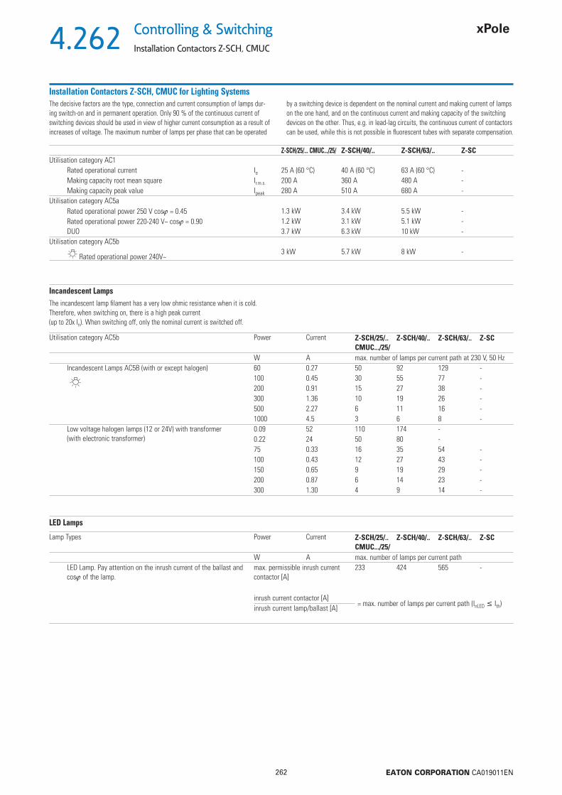
4.262
262 EATON CORPORATION CA019011EN
Controlling & Switching
Installation Contactors Z-SCH, CMUC
Installation Contactors Z-SCH, CMUC for Lighting Systems
Z-SCH/25/... CMUC.../25/ Z-SCH/40/.. Z-SCH/63/.. Z-SCUtilisation category AC1
Rated operational current Ie 25 A (60 °C) 40 A (60 °C) 63 A (60 °C) -Making capacity root mean square Ir.m.s. 200 A 360 A 480 A -Making capacity peak value Ipeak 280 A 510 A 680 A -
Utilisation category AC5aRated operational power 250 V cos = 0.45 1.3 kW 3.4 kW 5.5 kW -Rated operational power 220-240 V~ cos = 0.90 1.2 kW 3.1 kW 5.1 kW -DUO 3.7 kW 6.3 kW 10 kW -
Utilisation category AC5b
Rated operational power 240V~3 kW 5.7 kW 8 kW -
The decisive factors are the type, connection and current consumption of lamps dur-ing switch-on and in permanent operation. Only 90 % of the continuous current of switching devices should be used in view of higher current consumption as a result of increases of voltage. The maximum number of lamps per phase that can be operated
by a switching device is dependent on the nominal current and making current of lamps on the one hand, and on the continuous current and making capacity of the switching devices on the other. Thus, e.g. in lead-lag circuits, the continuous current of contactors can be used, while this is not possible in fl uorescent tubes with separate compensation.
Incandescent LampsThe incandescent lamp fi lament has a very low ohmic resistance when it is cold. Therefore, when switching on, there is a high peak current (up to 20x In). When switching off, only the nominal current is switched off.
Utilisation category AC5b Power Current Z-SCH/25/..CMUC.../25/
Z-SCH/40/.. Z-SCH/63/.. Z-SC
W A max. number of lamps per current path at 230 V, 50 HzIncandescent Lamps AC5B (with or except halogen)
60 0.27 50 92 129 -100 0.45 30 55 77 -200 0.91 15 27 38 -300 1.36 10 19 26 -500 2.27 6 11 16 -1000 4.5 3 6 8 -
Low voltage halogen lamps (12 or 24V) with transformer (with electronic transformer)
0.09 52 110 174 -0.22 24 50 80 -75 0.33 16 35 54 -100 0.43 12 27 43 -150 0.65 9 19 29 -200 0.87 6 14 23 -300 1.30 4 9 14 -
LED Lamps
Lamp Types Power Current Z-SCH/25/..CMUC.../25/
Z-SCH/40/.. Z-SCH/63/.. Z-SC
W A max. number of lamps per current pathLED Lamp. Pay attention on the inrush current of the ballast and cos of the lamp.
max. permissible inrush current contactor [A]
233 424 565 -
inrush current contactor [A]= max. number of lamps per current path (InLED Ith)inrush current lamp/ballast [A]

4.263
263 EATON CORPORATION CA019011EN
Controlling & SwitchingInstallation Contactors Z-SCH, CMUC
Fluorescent Tubes, Mercury Arc Lamps
Utilisation category AC5a Power Current Capacitor Z-SCH/25/..CMUC.../25/
Z-SCH/40/.. Z-SCH/63/.. Z-SC
Lamp Types W A μF max. number of lamps per current path at 230 V, 50 HzFluorescent tubes without compensation or with series compensation
11 0.16 1.3 75 210 310 -18 0.37 2.7 34 90 140 -24 0.35 2.5 34 90 140 -36 0.43 3.4 30 70 140 -58 0.67 5.3 20 45 70 -65 0.67 5.3 19 40 65 -85 0.8 5.3 16 35 60 -
Fluorescent tubes lead-lag circuit 11 0.07 - 2 x 110 2 x 220 2 x 250 -18 0.11 - 2 x 55 2 x 130 2 x 200 -24 0.14 - 2 x 44 2 x 110 2 x 160 -36 0.22 - 2 x 33 2 x 70 2 x 100 -58 0.35 - 2 x 22 2 x 46 2 x 70 -65 0.35 - 2 x 16 2 x 40 2 x 60 -85 0.47 - 2 x 11 2 x 30 2 x 40 -
Fluorescent tubes with parallel compensa-tion
11 0.16 3.0 43 67 107 -18 0.37 4.0 32 50 80 -24 0.35 4.0 32 50 80 -36 0.43 4.0 32 50 80 -58 0.67 7.0 18 36 46 -65 0.67 7.0 18 36 46 -85 0.8 8.0 16 33 44 -
Fluorescent tubes with electronic ballast 18 0.09 - 40 100 150 -36 0.16 - 20 50 75 -58 0.25 - 15 30 55 -80 0.4 - 10 20 30 -2 x 18 0.17 - 20 50 60 -2 x 36 0.32 - 10 25 30 -2 x 58 0.49 - 7 15 20 -
Mercury arc lamps, high pressure without compensation e.g.: HQL, HPL
50 0.61 - 21 38 55 -80 0.8 - 16 28 40 -125 1.15 - 11 20 28 -250 2.15 - 6 11 15 -400 3.25 - 4 7 10 -700 5.4 - 2 4 6 -1000 7.5 - 1 3 4 -
Mercury arc lamps, high pressure with com-pensation e.g.: HQL, HPL
50 0.28 7 18 36 50 -80 0.41 8 16 31 44 -125 0.65 10 13 25 35 -250 1.22 18 7 14 19 -400 1.95 25 5 10 14 -700 3.45 45 3 6 8 -1000 4.8 60 2 4 6 -
High- and low pressure discharge lamps with mercury vapour, with or without fl uores-cent-coated glass body are perfectly identical in their electrical behaviour. In order to limit the operational current and pre-conduction current, and to achieve the initial peak voltage, reactance coils are used as ballast. Capacitors are used for compensation of the resulting reactive current, which are either connected in series
with the coil (lead-lag circuit) or parallel to the mains (separate compensation, very rarely used now). The high making current in case of separate compensation (max. 30 x nominal current of the capacitor) which goes down quickly is usually attenuated considerably by the feed line.
Utilisation category AC5aFluorescent lamps without comp. or with series comp. I = IeAC1 x 0.5Lead-lag circuit (2x..) I = IeAC1 x 0.35Fluorescent tubes with parallel compensation I = Ipeak / 100 (take into account compensation capacitor)
I / ILampe = number of connectable lamps per current path
Fluorescent tubes with electronic ballast I = Ipeak / 50Mercury arc lamps, HD without compensation I = IeAC1 x 0.5Mercury arc lamps, HD with compensation I = Ipeak / 100 (take into account compensation capacitor)

4.264
264 EATON CORPORATION CA019011EN
Controlling & Switching
Installation Contactors Z-SCH, CMUC
Metal Halide Lamps
Power Current Capacitor Z-SCH/25/..CMUC.../25/
Z-SCH/40/.. Z-SCH/63/.. Z-SC
Lamp Types W A μF max. number of lamps per current path at 230 V, 50 HzMetal halide lamps without compensation e.g. HQI, HPI
35 0.53 - 28 57 - -70 1 - 15 30 - -150 1.8 - 8 17 - -250 3 - 5 10 - -400 3.5 - 4 8 - -1000 9.5 - 1 3 - -2000 16.5 - - 2 - -
400 V per pole 2000 10.5 - - 2 - -3500 18 - - 1 - -
Metal halide lamps with electronic ballast (50-125 xIn) HQI
20 0.1 i 9 18 20 -35 0.2 i 6 11 13 -70 0.36 i 5 12 12 -150 0.7 i 4 10 10 -
Metal halide lamps with compensation, with parallel compensation e.g. HQI, HPI
35 0.25 6 21 42 58 -70 0.45 12 11 21 29 -150 0.75 20 7 13 18 -250 1.5 33 4 9 11 -400 2.1 35 4 9 10 -1000 5.8 95 1 3 4 -2000 11.5 148 - 2 2 -
400 V per pole 2000 6.6 58 - 3 4 -3500 11.6 100 - 2 3 -
Transformers for low-voltage halogen lamps 20 - - 52 110 174 -50 - - 24 50 80 -75 - - 16 35 54 -100 - - 12 27 43 -150 - - 9 19 29 -200 - - 5 14 23 -300 - - 4 9 14 -
Metal halide lamps are a version of high-pressure mercury arc lamps with higher luminous effi ciency and fi delity of colour (metalloids [halogens] added to the mercury fi ll up the Hg-spectrum with its many gaps). Ballast and ignition devices are necessary. Starting time 3 ... 5 minutes at 1.4 - 2 x I.After switching on, it is not possible to light the lamp again immediately (lamp extin-guishes after a power cut-off of only 1/2 period). Therefore, in many cases in important
facilities ionisation of part of the lamps is maintained by switching over to 415 V, 500 Hz (e.g. to an emergency power supply). In this case, the lamp lights immediately after the mains voltage is on again. Otherwise, this would take several minutes. When using suitable ignition devices, the lamps can be lit again immediately.
I / ILampe = number of connectable lamps per current path
Metal halide lamps (HQI) without compensation I = IeAC1 x 0.5Metal halide lamps (HQI) with compensation I = Ipeak / 100 (take into account compensation capacitor)Transformer for low voltage halogen lamps I = Ipeak / 50
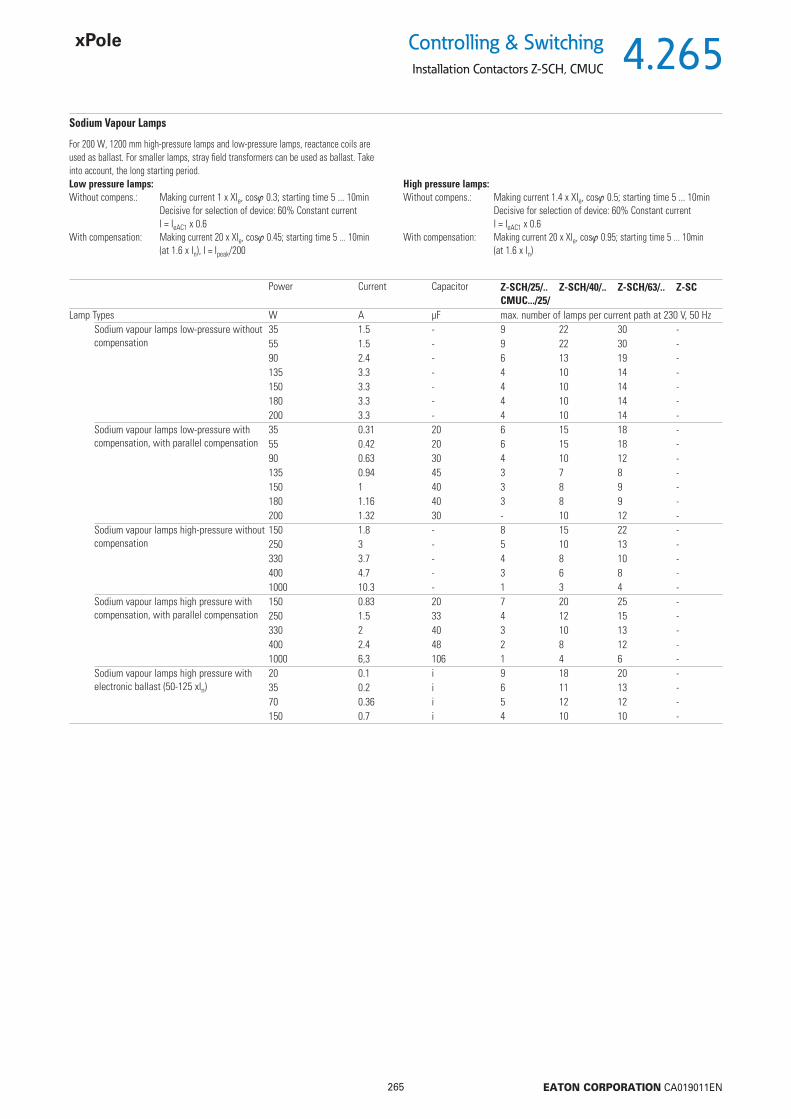
4.265
265 EATON CORPORATION CA019011EN
Controlling & SwitchingInstallation Contactors Z-SCH, CMUC
Sodium Vapour Lamps
Power Current Capacitor Z-SCH/25/..CMUC.../25/
Z-SCH/40/.. Z-SCH/63/.. Z-SC
Lamp Types W A μF max. number of lamps per current path at 230 V, 50 HzSodium vapour lamps low-pressure without compensation
35 1.5 - 9 22 30 -55 1.5 - 9 22 30 -90 2.4 - 6 13 19 -135 3.3 - 4 10 14 -150 3.3 - 4 10 14 -180 3.3 - 4 10 14 -200 3.3 - 4 10 14 -
Sodium vapour lamps low-pressure with compensation, with parallel compensation
35 0.31 20 6 15 18 -55 0.42 20 6 15 18 -90 0.63 30 4 10 12 -135 0.94 45 3 7 8 -150 1 40 3 8 9 -180 1.16 40 3 8 9 -200 1.32 30 - 10 12 -
Sodium vapour lamps high-pressure without compensation
150 1.8 - 8 15 22 -250 3 - 5 10 13 -330 3.7 - 4 8 10 -400 4.7 - 3 6 8 -1000 10.3 - 1 3 4 -
Sodium vapour lamps high pressure with compensation, with parallel compensation
150 0.83 20 7 20 25 -250 1.5 33 4 12 15 -330 2 40 3 10 13 -400 2.4 48 2 8 12 -1000 6,3 106 1 4 6 -
Sodium vapour lamps high pressure with electronic ballast (50-125 xIn)
20 0.1 i 9 18 20 -35 0.2 i 6 11 13 -70 0.36 i 5 12 12 -150 0.7 i 4 10 10 -
For 200 W, 1200 mm high-pressure lamps and low-pressure lamps, reactance coils are used as ballast. For smaller lamps, stray fi eld transformers can be used as ballast. Take into account, the long starting period.Low pressure lamps: Without compens.: Making current 1 x XIe, cos 0.3; starting time 5 ... 10min Decisive for selection of device: 60% Constant current I = IeAC1 x 0.6 With compensation: Making current 20 x XIe, cos 0.45; starting time 5 ... 10min (at 1.6 x In), I = Ipeak/200
High pressure lamps: Without compens.: Making current 1.4 x XIe, cos 0.5; starting time 5 ... 10min Decisive for selection of device: 60% Constant current I = IeAC1 x 0.6 With compensation: Making current 20 x XIe, cos 0.95; starting time 5 ... 10min (at 1.6 x In)

4.266
266 EATON CORPORATION CA019011EN
Controlling & Switching
Installation Contactors Z-SCH, CMUC
Utilisation Categories of Contactors
Type of current
Utilisationcategory
Typical Applications Verifi cation of electrical ser-vice life
Verifi cation of switching capacity
l = Making current, Ic = Breaking current,Ie = Rated operational current, U = Voltage, Switching on Switching off Switching on Switching offUe = Rated operational voltage, Ie I U cos Ic Ur cos Ie I U cos Ic Ur cosUr = Recovery voltage A Ie Ue Ie Ue A Ie Ue Ie Ue
AC AC-1 Non-inductive or slightly inductive loadResistance furnaces
all values
1 1 0.95 1 1 0.95 all values
1.5 1.05 0.8 1.5 1.05 0.8
AC-2 Slip ring motors: starting, switching off all values
2.5 1 0.65 2.5 1 0.65 all values
4 1.05 0.65 4 1.05 0.8
AC-3 Squirrel cage motors: starting, switching off Ie 17 6 1 0.65 1 0.17 0.65 Ie 100 10 1.05 0.45 8 1.05 0.45(running motors4)) Ie > 17 6 1 0.35 1 0.17 0.35 Ie > 100 8 1.05 0.35 6 1.05 0.35
AC-4 Squirrel cage motors: starting, plugging Ie 17 6 1 0.65 6 1 0.65 Ie 100 12 1.05 0.45 10 1.05 0.45reversing, inching Ie > 17 6 1 0.35 6 1 0.35 Ie > 100 10 1.05 0.35 8 1.05 0.35
AC-5 Switching of electric discharge lamp controls 3.0 1.05 0.45 3.0 1.05 0.45AC-5b Switching of incandescent lamps 1.52) 1.05 2) 1.052) 1.05 2)
AC-6a3) Switching of transformersAC-6b3) Switching of capacitor banksAC-7a Slightly inductive loads in household applian-
ces and similar applicationsaccording to manufac-turer specifi cations
1.5 1.05 0.8 1.5 1.05 0.8
AC-7b Motor loads for household appliances 8,0 1.05 1) 8,0 1.05 1)
AC-8a Switching of hermetically enclosed refrigerant compressor motors with manual reset of over-load releases5)
6,0 1.05 1) 6,0 1.05 1)
AC-8b Switching of hermetically enclosed refrigerant compressor motors with automatic reset of overload releases5)
6,0 1.05 1) 6,0 1.05 1)
DC DC-1 Non-inductive or slightly inductive load, Resistance furnaces
all values
1 1 1 1 1 1 all values
1.5 1.05 1 1.5 1.05 1
DC-3 Shunt motors: starting, plugging, reversing, inching, dynamic braking
all values
2.5 1 2 2.5 1 2 all values
4 1.05 2.5 4 1.05 2.5
DC-5 Series motors: starting, plugging, reversing, inching, dynamic braking
all values
2 1 7.5 2.5 1 7.5 all values
4 1.05 2.5 4 1.05 2.5
DC-6 Switching of incandescent lamps 1.52) 1.05 2) 1.52) 1.05 2)
acc. to IEC 947-4-1, EN 60 947 VDE 0660 Part 102
1) cos = 0.45 for Ie 100 A; cos = 0.35 for Ie 100 A.2) The tests must be carried out with an incandescent lamp load connected.3) In this case, the test data must be derived from the test values for AC-3 or AC-4 according to
a special table.4) Devices for utilisation category AC-3 may be used for occasional inching or plugging during
a limited period, such as for setting up a machine. However, during this limited period of time, the number of operations must not exceed fi ve per minute or ten in a ten minute peri-od.
5) Hermetically enclosed refrigerant compressor motor means a combination of a compressor and a motor both of which are housed in the same enclosure with no external shaft or shaft seals, the motor running in the refrigerant.

4.267
267 EATON CORPORATION CA019011EN
Controlling & SwitchingInstallation Contactors Z-SCH, CMUC
Utilisation Categories of Auxiliary Switches
Type of current
Utilisationcategory
Typical Applications Normal conditions of use
Divergent conditions of use
l = Making current, Ic = Breaking current,Ie = Rated operational current, U = Voltage, Switching on Switching off Switching on Switching offUe = Rated operational voltage, I U cos Ic Ur cos I U cos Ic Ur cosUr = Recovery voltage, Ie Ue Ie Ue Ie Ue Ie Ue
t0.95 = the time in ms until 95% of the stationa-ry current has been reached,P = Ue x Ie = Rated power in Watts
AC AC-12 Control of resistive and solid state loads in optocoupler input circuits
1 1 0.9 1 1 0.9 - - - - - -
AC-13 Control of solid state loads with transforme-risolation
2 1 0.65 1 1 0.65 10 1.1 0.65 1.1 1.1 0.65
AC-14 Control of small electromagnetic loads (max. 72 VA)
6 1 0.3 1 1 0.3 6 1.1 0.7 6 1.1 0.7
AC-15 Control of electromagnetic loads (above 72 VA)
10 1 0.3 1 1 0.3 10 1.1 0.3 10 1.1 0.3
I U t0.95 Ic Ur t0.95 I U t0.95 Ic Ur t0.95
Ie Ue Ie Ue Ie Ue Ie Ue
DC DC-12 Control of resistive and solid state loads in optocoupler input circuits
1 1 1 ms 1 1 1 ms - - - - - -
DC-13 Control of electromagnets 1 1 6xP1) 1 1 6xP1) 1.1 1.1 6xP1) 1.1 1.1 6xP1)
DC-14 Control of electromagnetic loads with economy resistors in the circuit
10 1 15 ms 1 1 15 ms 10 1.1 15 ms 10 1.1 15 ms
acc. to IEC 947-4-1, EN 60 947 VDE 0660 Part 102
1) The value „6xP“ is the result of an empirical relationship which is found to represent most direct current magnetic loads up to an upper limit of P = 50W with 6 [ms]/[W] = 200 [ms]. Loads with a rated power above 50 W are composed of small loads located parallel to each other. Therefore, 300 ms is an upper limit independent of the power rating.

4.268
268 EATON CORPORATION CA019011EN
Controlling & Switching
Impulse Relays Z-S
Z-S230/SO
Impulse Relays Z-S
Control Voltage Function MU TypeDesignation
Article No. Units perpackage
SG59611 240 V 50Hz 1NO 1 Z-S240/S 265261 2 / 120240 V 50Hz 2NO 1 Z-S240/SS 265269 2 / 120240 V 50Hz 1NO+1NC 1 Z-S240/SO 265282 2 / 120240 V 50Hz 2NO+2NC 2 Z-S240/2S2O 265304 1 / 60240 V 50Hz 1CO 1 Z-S240/W 265289 2 / 120240 V 50Hz 2CO 2 Z-S240/WW 265311 1 / 60240 V 60Hz 2NO 1 Z-S241/SS 265268 2 / 120230 V 50Hz 1NO 1 Z-S230/S 265262 2 / 120230 V 50Hz 2NO 1 Z-S230/SS 265271 2 / 120230 V 50Hz 4NO 2 Z-S230/4S 270335 1 / 60230 V 50Hz 1NO+1NC 1 Z-S230/SO 265283 2 / 120230 V 50Hz 2NO+2NC 2 Z-S230/2S2O 265305 1 / 60230 V 50Hz 1CO 1 Z-S230/W 265290 2 / 120230 V 50Hz 2CO 2 Z-S230/WW 265312 1 / 60230 V 60Hz 2NO 1 Z-S231/SS 265270 2 / 120110 V 50Hz 1NO 1 Z-S110/S 265263 2 / 120110 V 50Hz 2NO 1 Z-S110/SS 265273 2 / 120110 V 50Hz 1NO+1NC 1 Z-S110/SO 265284 2 / 120110 V 50Hz 2NO+2NC 2 Z-S110/2S2O 265306 1 / 60110 V 50Hz 1CO 1 Z-S110/W 265291 2 / 120110 V 50Hz 2CO 2 Z-S110/WW 265313 1 / 60110 V 60Hz 2NO 1 Z-S111/SS 265272 2 / 120110 V DC 2NO 1 Z-S109/SS 265274 2 / 120110 V DC 1CO 1 Z-S109/W 265292 2 / 120110 V DC 2CO 2 Z-S109/WW 265314 1 / 6048VAC/24VDC*) 1NO 1 Z-S48/S 265534 2 / 12048VAC/24VDC*) 2NO 1 Z-S48/SS 265536 2 / 12048VAC/24VDC*) 4NO 2 Z-S48/4S 100665 1 / 6048VAC/24VDC*) 1NO+1NC 1 Z-S48/SO 265538 2 / 12048VAC/24VDC*) 2NO+2NC 2 Z-S48/2S2O 265540 1 / 6048VAC/24VDC*) 1CO 1 Z-S48/W 265544 2 / 12048VAC/24VDC*) 2CO 2 Z-S48/WW 265542 1 / 6024VAC/12VDC*) 1NO 1 Z-S24/S 265535 2 / 12024VAC/12VDC*) 2NO 1 Z-S24/SS 265537 2 / 12024VAC/12VDC*) 1NO+1NC 1 Z-S24/SO 265539 2 / 12024VAC/12VDC*) 2NO+2NC 2 Z-S24/2S2O 265541 1 / 6024VAC/12VDC*) 1CO 1 Z-S24/W 265545 2 / 12024VAC/12VDC*) 2CO 2 Z-S24/WW 265543 1 / 6024 V 60Hz 2NO 1 Z-S25/SS 265276 2 / 12012 V 50Hz 1NO 1 Z-S12/S 265266 2 / 12012 V 50Hz 2NO 1 Z-S12/SS 265278 2 / 12012 V 50Hz 1NO+1NC 1 Z-S12/SO 265287 2 / 12012 V 50Hz 2NO+2NC 2 Z-S12/2S2O 265309 1 / 6012 V 50Hz 1CO 1 Z-S12/W 265296 2 / 12012 V 50Hz 2CO 2 Z-S12/WW 265317 1 / 608 V 50Hz 1NO 1 Z-S8/S 265267 2 / 1208 V 50Hz 2NO 1 Z-S8/SS 265280 2 / 1208 V 50Hz 1NO+1NC 1 Z-S8/SO 265288 2 / 1208 V 50Hz 2NO+2NC 2 Z-S8/2S2O 265310 1 / 608 V 50Hz 1CO 1 Z-S8/W 265297 2 / 1208 V 50Hz 2CO 2 Z-S8/WW 265318 1 / 608 V DC 2NO 1 Z-S7/SS 265281 2 / 1208 V DC 1CO 1 Z-S7/W 265298 2 / 1208 V DC 2CO 2 Z-S7/WW 265319 1 / 60
*) Doppelspannung AC/DC
• 16 A 250 VAC
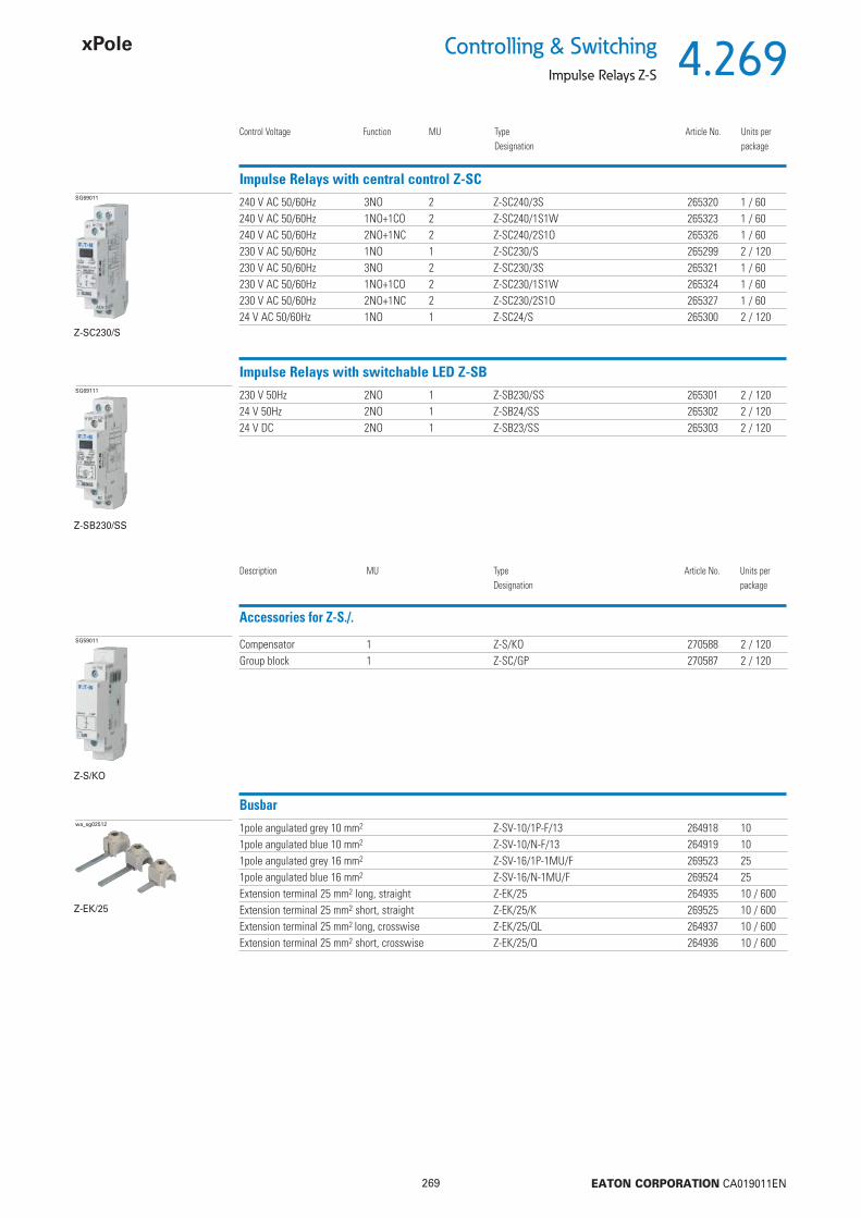
4.269
269 EATON CORPORATION CA019011EN
Controlling & SwitchingImpulse Relays Z-S
Z-SC230/S
Impulse Relays with central control Z-SC
Control Voltage Function MU TypeDesignation
Article No. Units perpackage
SG69011 240 V AC 50/60Hz 3NO 2 Z-SC240/3S 265320 1 / 60240 V AC 50/60Hz 1NO+1CO 2 Z-SC240/1S1W 265323 1 / 60240 V AC 50/60Hz 2NO+1NC 2 Z-SC240/2S1O 265326 1 / 60230 V AC 50/60Hz 1NO 1 Z-SC230/S 265299 2 / 120230 V AC 50/60Hz 3NO 2 Z-SC230/3S 265321 1 / 60230 V AC 50/60Hz 1NO+1CO 2 Z-SC230/1S1W 265324 1 / 60230 V AC 50/60Hz 2NO+1NC 2 Z-SC230/2S1O 265327 1 / 6024 V AC 50/60Hz 1NO 1 Z-SC24/S 265300 2 / 120
Z-SB230/SS
Impulse Relays with switchable LED Z-SBSG69111 230 V 50Hz 2NO 1 Z-SB230/SS 265301 2 / 120
24 V 50Hz 2NO 1 Z-SB24/SS 265302 2 / 12024 V DC 2NO 1 Z-SB23/SS 265303 2 / 120
Busbarwa_sg02512 1pole angulated grey 10 mm2 Z-SV-10/1P-F/13 264918 10
1pole angulated blue 10 mm2 Z-SV-10/N-F/13 264919 101pole angulated grey 16 mm2 Z-SV-16/1P-1MU/F 269523 251pole angulated blue 16 mm2 Z-SV-16/N-1MU/F 269524 25Extension terminal 25 mm2 long, straight Z-EK/25 264935 10 / 600Extension terminal 25 mm2 short, straight Z-EK/25/K 269525 10 / 600Extension terminal 25 mm2 long, crosswise Z-EK/25/QL 264937 10 / 600Extension terminal 25 mm2 short, crosswise Z-EK/25/Q 264936 10 / 600
Z-EK/25
Accessories for Z-S./.SG59011 Compensator 1 Z-S/KO 270588 2 / 120
Group block 1 Z-SC/GP 270587 2 / 120
Description MU TypeDesignation
Article No. Units perpackage
Z-S/KO

4.270
270 EATON CORPORATION CA019011EN
Controlling & Switching
Impulse Relays Z-S (excluded Z-SC)
Description Impulse Relays Z-S
• Impulse relays according to EN/IEC 60669 for switching electrical consumers in impulse operation.• Shape and terminal compatible with the installation relay range• Manual operation for testing purposes is possible• Separately switchable LED (Z-SB../SS) for signalling purposes• Glow lamps of illuminated pushbuttons connected parallel produce reactive currents which may be compensated by a capacitor block in order to prevent excessive heating of
coils in case of high numbers of glow lamps.• Glow lamps parallel to control keys according to table• Main contacts can be connected to standard pin busbar
Security:• Optional optical operating status display by means of LED• Switching position indicated on the front side by manual operating key• All terminals - coil and contacts - equipped with guide for secure terminal connection. Misplacement of wires impossible.• Made of hardly fl ammable materials and plastics free from chlorine and halogens.• Finger and hand touch safe according to VBG4
Advantages:• Available in two versions (Z-S., Z-SB.)• Low switching noise and no humming• Easy to connect thanks to large terminals which are supplied open• Simple snap-on fastening on 35 mm DIN rail• High degree of fl exibility thanks to a variety of contact confi gurations• Easy access for coil connection
Accessories:Capacitor block Z-S/KO 270588
Connection diagram 1MU Z-S./.“S” “SS” “W” Z-SB../SS1 NO 2 NO 1 CO 2 NO
2MU Z-S./.“WW” “2S2O”2 CO 2 NO / 2 NC
Dimensions (mm)Z-S/KO
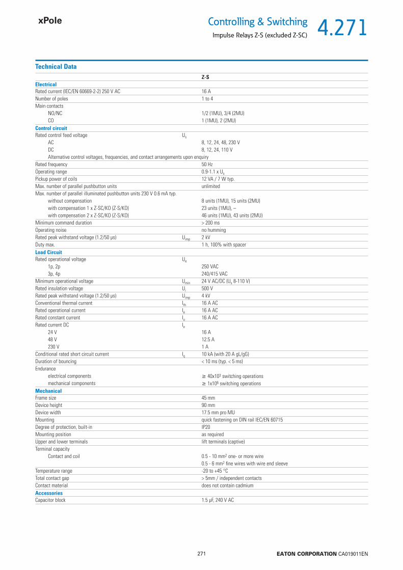
4.271
271 EATON CORPORATION CA019011EN
Controlling & SwitchingImpulse Relays Z-S (excluded Z-SC)
Technical DataZ-S
ElectricalRated current (IEC/EN 60669-2-2) 250 V AC 16 ANumber of poles 1 to 4Main contacts
NO/NC 1/2 (1MU), 3/4 (2MU)CO 1 (1MU), 2 (2MU)
Control circuitRated control feed voltage Us
AC 8, 12, 24, 48, 230 VDC 8, 12, 24, 110 VAlternative control voltages, frequencies, and contact arrangements upon enquiry
Rated frequency 50 HzOperating range 0.9-1.1 x Us
Pickup power of coils 12 VA / 7 W typ.Max. number of parallel pushbutton units unlimitedMax. number of parallel illuminated pushbutton units 230 V 0.6 mA typ.
without compensation 8 units (1MU), 15 units (2MU)with compensation 1 x Z-SC/KO (Z-S/KO) 23 units (1MU), –with compensation 2 x Z-SC/KO (Z-S/KO) 46 units (1MU), 43 units (2MU)
Minimum command duration > 200 msOperating noise no hummingRated peak withstand voltage (1.2/50 μs) Uimp 2 kVDuty max. 1 h, 100% with spacerLoad CircuitRated operational voltage Ue
1p, 2p 250 VAC3p, 4p 240/415 VAC
Minimum operational voltage Umin 24 V AC/DC (Us 8-110 V)Rated insulation voltage Ui 500 VRated peak withstand voltage (1.2/50 μs) Uimp 4 kVConventional thermal current Ith 16 A ACRated operational current Ie 16 A ACRated constant current Iu 16 A ACRated current DC Ie
24 V 16 A48 V 12.5 A230 V 1 A
Conditional rated short circuit current Iq 10 kA (with 20 A gL/gG)Duration of bouncing < 10 ms (typ. < 5 ms)Endurance
electrical components 40x103 switching operationsmechanical components 1x10⁶ switching operations
MechanicalFrame size 45 mmDevice height 90 mmDevice width 17.5 mm pro MUMounting quick fastening on DIN rail IEC/EN 60715Degree of protection, built-in IP20Mounting position as requiredUpper and lower terminals lift terminals (captive)Terminal capacity
Contact and coil 0.5 - 10 mm2 one- or more wire0.5 - 6 mm2 fi ne wires with wire end sleeve
Temperature range -20 to +45 °CTotal contact gap > 5mm / independent contactsContact material does not contain cadmiumAccessoriesCapacitor block 1.5 μF, 240 V AC
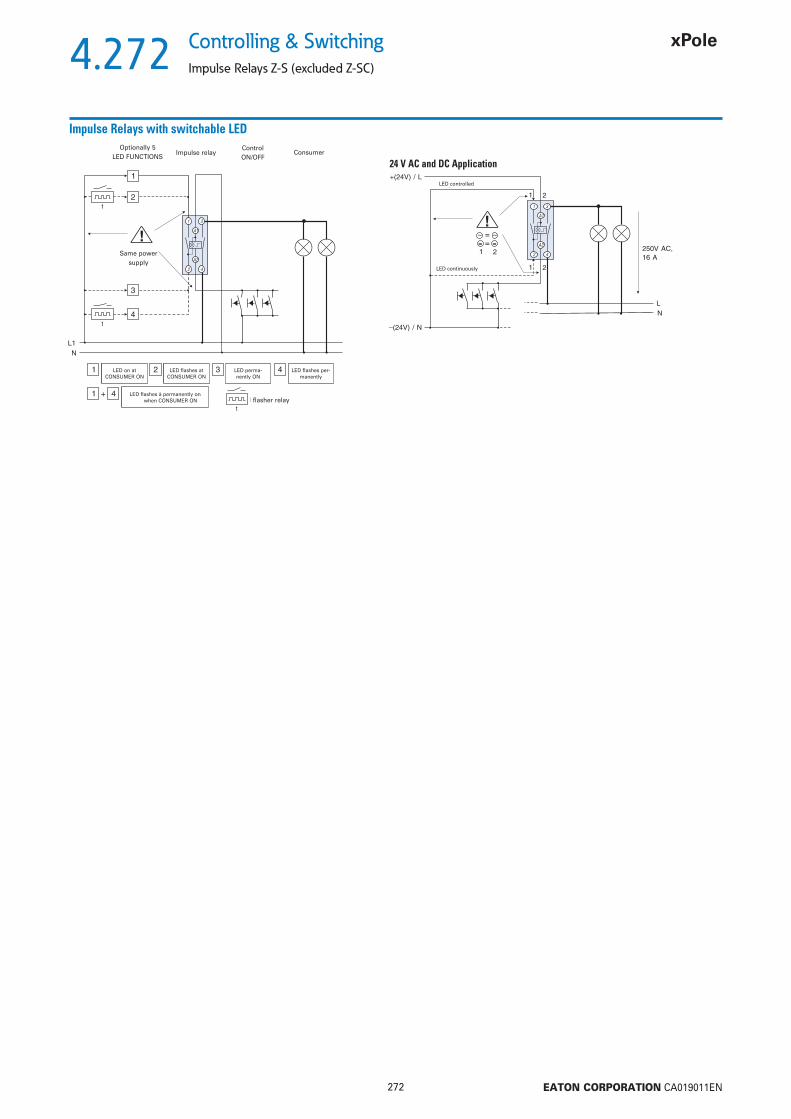
4.272
272 EATON CORPORATION CA019011EN
Controlling & Switching
Impulse Relays Z-S (excluded Z-SC)
Impulse Relays with switchable LED
24 V AC and DC Application
Optionally 5LED FUNCTIONS
Impulse relayControlON/OFF
Consumer
Same power supply
LED on at CONSUMER ON
LED fl ashes at CONSUMER ON
LED perma-nently ON
LED fl ashes per-manently
LED fl ashes à permanently on when CONSUMER ON fl asher relay
LED controlled
LED continuously
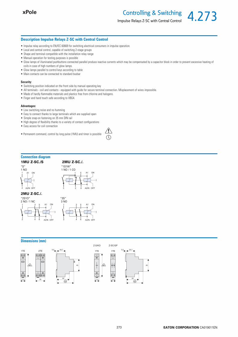
4.273
273 EATON CORPORATION CA019011EN
Controlling & SwitchingImpulse Relays Z-SC with Central Control
Description Impulse Relays Z-SC with Central Control
• Impulse relay according to EN/IEC 60669 for switching electrical consumers in impulse operation.• Local and central control, capable of switching 2-stage groups • Shape and terminal compatible with the installation relay range• Manual operation for testing purposes is possible• Glow lamps of illuminated pushbuttons connected parallel produce reactive currents which may be compensated by a capacitor block in order to prevent excessive heating of
coils in case of high numbers of glow lamps.• Glow lamps parallel to control keys according to table• Main contacts can be connected to standard busbar
Security:• Switching position indicated on the front side by manual operating key• All terminals - coil and contacts - equipped with guide for secure terminal connection. Misplacement of wires impossible. • Made of hardly fl ammable materials and plastics free from chlorine and halogens. • Finger and hand touch safe according to VBG4.
Advantages:• Low switching noise and no humming• Easy to connect thanks to large terminals which are supplied open• Simple snap-on fastening on 35 mm DIN rail• High degree of fl exibility thanks to a variety of contact confi gurations• Easy access for coil connection
• Permanent command, control by long pulse (1MU) and timer is possible
Connection diagram 1MU Z-SC./S 2MU Z-SC./.“S”1 NO
2MU Z-SC./.“2S1O” “3S”2 NO / 1 NC 3 NO
“1S1W”1 NO / 1 CO
Dimensions (mm)
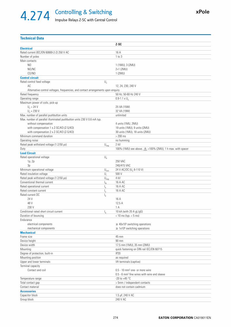
4.274
274 EATON CORPORATION CA019011EN
Controlling & Switching
Impulse Relays Z-SC with Central Control
Technical DataZ-SC
ElectricalRated current (IEC/EN 60669-2-2) 250 V AC 16 ANumber of poles 1 to 3Main contacts
NO 1 (1MU), 3 (2MU)NO/NC 2+1 (2MU)CO/NO 1 (2MU)
Control circuitRated control feed voltage Us
AC 12, 24, 230, 240 VAlternative control voltages, frequencies, and contact arrangements upon enquiry
Rated frequency 50 Hz; 50-60 Hz 240 VOperating range 0.9-1.1 x Us
Maximum power of coils, pick-upUs = 24 V 25 VA (15W)Us = 230 V 32 VA (19W)
Max. number of parallel pushbutton units unlimitedMax. number of parallel illuminated pushbutton units 230 V 0.6 mA typ.
without compensation 4 units (1MU, 2MU)with compensation 1 x Z-SC/KO (Z-S/KO) 19 units (1MU), 9 units (2MU)with compensation 2 x Z-SC/KO (Z-S/KO) 30 units (1MU), 18 units (2MU)
Minimum command duration > 200 msOperating noise no hummingRated peak withstand voltage (1.2/50 μs) Uimp 2 kVDuty 100% (1MU) see above, <100% (2MU), 1 h max. with spacerLoad CircuitRated operational voltage Ue
1p, 2p 250 VAC3p 240/415 VAC
Minimum operational voltage Umin 24 V AC/DC (Us 8-110 V)Rated insulation voltage Ui 500 VRated peak withstand voltage (1.2/50 μs) Uimp 4 kVConventional thermal current Ith 16 A ACRated operational current Ie 16 A ACRated constant current Iu 16 A ACRated current DC Ie
24 V 16 A48 V 12.5 A230 V 1 A
Conditional rated short circuit current Iq 10 kA (with 20 A gL/gG)Duration of bouncing < 10 ms (typ. < 5 ms)Endurance
electrical components 40x103 switching operationsmechanical components 1x10⁶ switching operations
MechanicalFrame size 45 mmDevice height 90 mmDevice width 17.5 mm (1MU), 35 mm (2MU)Mounting quick fastening on DIN rail IEC/EN 60715Degree of protection, built-in IP20Mounting position as requiredUpper and lower terminals lift terminals (captive)Terminal capacity
Contact and coil 0.5 - 10 mm2 one- or more wire0.5 - 6 mm2 fi ne wires with wire end sleeve
Temperature range -20 to +45 °CTotal contact gap > 5mm / independent contactsContact material does not contain cadmiumAccessoriesCapacitor block 1.5 μF, 240 V ACGroup block 240 V AC
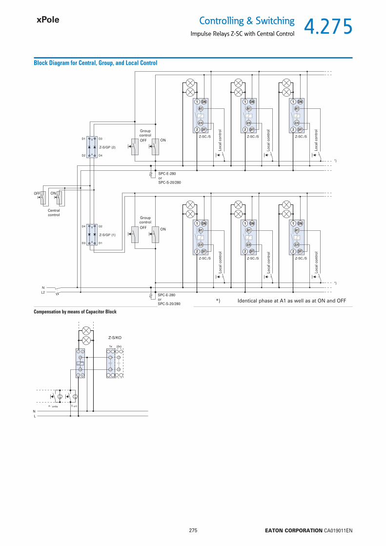
4.275
275 EATON CORPORATION CA019011EN
Controlling & SwitchingImpulse Relays Z-SC with Central Control
Block Diagram for Central, Group, and Local Control
Compensation by means of Capacitor Block
SPC-E-280orSPC-S-20/280
Group control
Loca
l con
trol
Central control
OFF ON
Group controlOFF ON
OFF ON
Loca
l con
trol
Loca
l con
trol
Loca
l con
trol
Loca
l con
trol
Loca
l con
trol
SPC-E-280orSPC-S-20/280
*) Identical phase at A1 as well as at ON and OFF
units unit

4.276
276 EATON CORPORATION CA019011EN
Controlling & Switching
Impulse Relays Z-S, Z-SC, Z-SB
Utilisation categories (accoording to IEC/EN 60947-4-1)
Utilisation categories 1MU (1S, 2S, 1S+1O, 1W), 2MU (2S+2O, 2W, 3S+1O) Z-S, Z-ZC, Z-SB
AC-1 Rated operational voltage Ue 250 V ACRated operational current Ie 16 A ACRated operational power AC-1 3200 W (cos = 0.8), 4000 VAMake-/break-current AC-1 Ic 24 A AC
AC-3 Rated operational voltage Ue 250 V ACRated operational current Ie 8 A ACRated operational power AC-3 900 W (cos = 0.45), 2000 VAMake-/break-current AC-3 Ic 80 A AC
AC-5a Rated operational voltage Ue 250 V ACRated operational current Ie 10 A ACRated operational power AC-5a 1125 W (cos = 0.45), 2500 VAMake-/break-current AC-5a Ic 30 A AC
AC-5b Rated operational voltage Ue 230 V ACRated operational current Ie 8.8 A ACRated operational power AC-5b 2024 WMake-/break-current AC-5b Ic 13.2 A AC
AC-7a (according toEN 61095) Rated operational voltage Ue 250 V ACRated operational current Ie 16 A ACRated operational power AC-7a 3200 W (cos = 0.8), 4000 VAMake-/break-current AC-7a Ic 24 A AC
Utilisation categories 2MU (3S, 4S)
AC-1 Rated operational voltage Ue 240/415 V ACRated operational current Ie 16 A ACRated operational power AC-1 3200 W (cos = 0.8), 4000 VAMake-/break-current AC-1 Ic 24 A AC
AC-3 Rated operational voltage Ue 240/415 V ACRated operational current Ie 8 A ACRated operational power AC-3 900 W (cos = 0.45), 2000 VAMake-/break-current AC-3 Ic 80 A AC / 64 A AC
AC-5a Rated operational voltage Ue 240/415 V ACRated operational current Ie 10 A ACRated operational power AC-5a 1125 W (cos = 0.45), 2500 VAMake-/break-current AC-5a Ic 30 A AC
AC-5b Rated operational voltage Ue 230/400 V ACRated operational current Ie 8.8 A ACRated operational power AC-5b 2024 WMake-/break-current AC-5b Ic 13.2 A AC
AC-7a (according toEN 61095) Rated operational voltage Ue 240/415 V ACRated operational current Ie 16 A ACRated operational power AC-7a 3200 W (cos = 0.8), 4000 VAMake-/break-current AC-7a Ic 24 A AC
AC-7b (according toEN 61095) Rated operational voltage Ue 240/415 V ACRated operational current Ie 10 A ACRated operational power AC-7b 1125 W (cos = 0.8), 2500 VAMake-/break-current AC-7b Ic 30 A AC
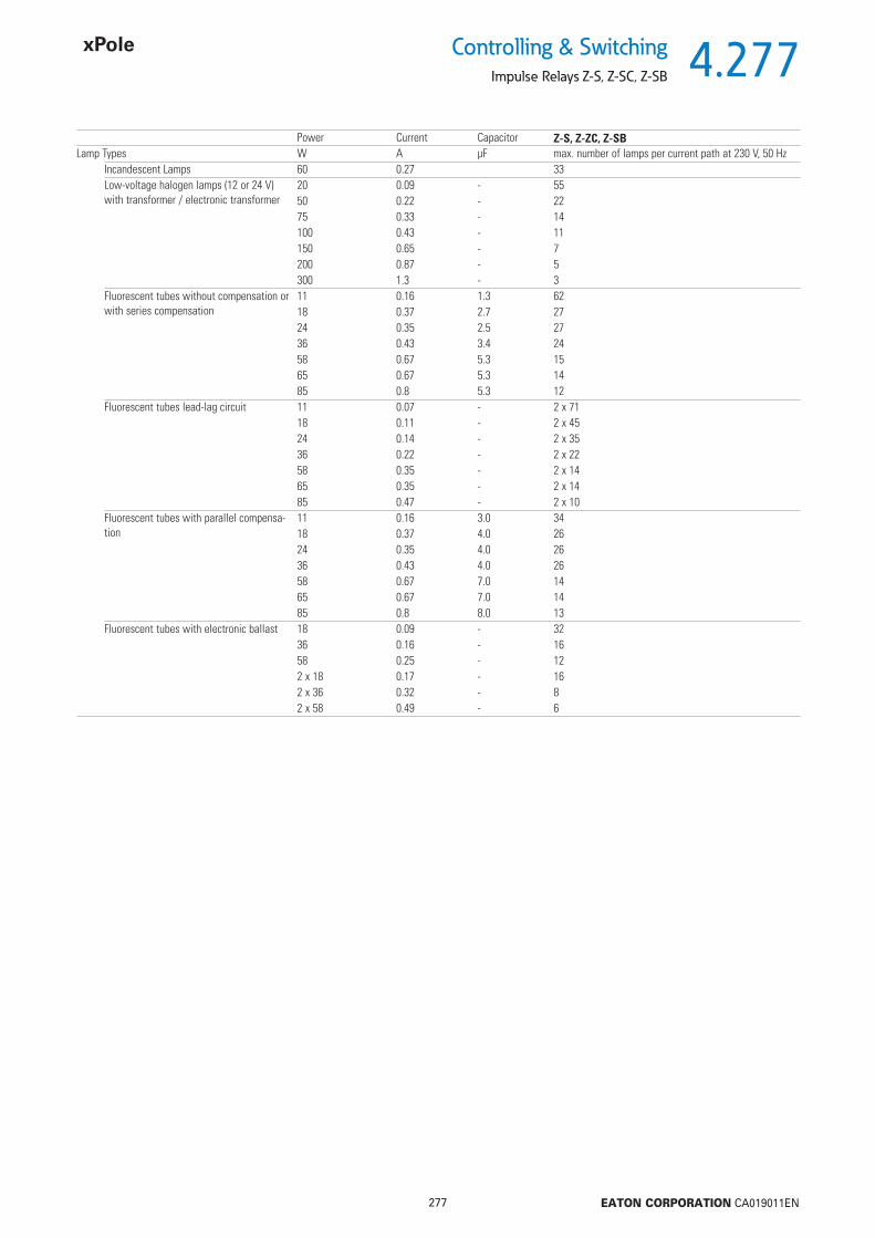
4.277
277 EATON CORPORATION CA019011EN
Controlling & SwitchingImpulse Relays Z-S, Z-SC, Z-SB
Power Current Capacitor Z-S, Z-ZC, Z-SBLamp Types W A μF max. number of lamps per current path at 230 V, 50 Hz
Incandescent Lamps 60 0.27 33Low-voltage halogen lamps (12 or 24 V) with transformer / electronic transformer
20 0.09 - 5550 0.22 - 2275 0.33 - 14100 0.43 - 11150 0.65 - 7200 0.87 - 5300 1.3 - 3
Fluorescent tubes without compensation or with series compensation
11 0.16 1.3 6218 0.37 2.7 2724 0.35 2.5 2736 0.43 3.4 2458 0.67 5.3 1565 0.67 5.3 1485 0.8 5.3 12
Fluorescent tubes lead-lag circuit 11 0.07 - 2 x 7118 0.11 - 2 x 4524 0.14 - 2 x 3536 0.22 - 2 x 2258 0.35 - 2 x 1465 0.35 - 2 x 1485 0.47 - 2 x 10
Fluorescent tubes with parallel compensa-tion
11 0.16 3.0 3418 0.37 4.0 2624 0.35 4.0 2636 0.43 4.0 2658 0.67 7.0 1465 0.67 7.0 1485 0.8 8.0 13
Fluorescent tubes with electronic ballast 18 0.09 - 3236 0.16 - 1658 0.25 - 122 x 18 0.17 - 162 x 36 0.32 - 82 x 58 0.49 - 6

4.278
278 EATON CORPORATION CA019011EN
Controlling & Switching
Staircase Switch with switch-off warning and stop function TL
Staircase Switch with switch-off warning and stop function TLSG07312 Staircase switch with switchoff warning and stop function TLE 101064 2 / 120
Staircase switch as TLE, with additional control input for central control, zero-voltage proof
TLK 101066 2 / 120
Function TypeDesignation
Article No. Units perpackage
Description Staircase Switch with switch-off warning and stop function TL
• Automatic electronic staircase switch• Switch-off warning can be switched off (type TLK)• Subsequent switching is possible, programmable long-time function• Power saving function, low switching noise
• Automatic 3-/4 wire circuit recognition• Zero voltage safety thanks to memory function (type TLK)• Central control function (type TLK)• External voltage control input (type TLK)
Connection diagram
LN
L
B1 N
N
L
B1
18
18
e.g. 3 wire circuit TLE e.g. 4 wire circuit with attic lighting TLK
LN
C1L
C2
B1 N
N
L
B1
8-230VAC/DC
18
18
Dimensions (mm)
45
17,5
87
45
TLK
60
17,5
87
TLE
Functional Description
.5
TLE
15
TLK
Zeitautomatik mit Abschaltvorwarnung
Dauerlicht
Ausgeschaltet
Stromstoßschalter
Stromstoßschalter nullspannungssichert [min.]
t [min.]
0,53
6
915
Mode:
Zeitautomatik2000 W
1000 W
500 W
max. 100 mA
5
10
Modes
Automatic timing
Automatic timing with switch-off warning
Permanent light
Off
Impulse relay
Impulse relay, zero-voltage proof
B1
Rt
Mode
t 2t 3t
>2s <2s >2s <2s
R15s 10s 5s
Mode
R
Automatic timing :After pushing the button the output relay closes (terminals L-18) and the set time starts to run. If the button is pushed again before the time t has lapsed the time re-starts from zero (subsequent switching function in accordance with EN 60669-2-3). Repeated quick pressing of the pushbutton („pumping“) leads to the addition of 2, 3 or more time intervals up to 60 min. Pushing the button once for a long time (> 2 s) stops the running lighting period, and the relay switches off (power saving function). In the function, the device generates short pulses (fl ickering) as a switch-of warning (according to DIN 18015-2), 15 s, 10 s, and 5 s prior to switching off.
The additional control input permits activating the staircase switch e.g. from an intercom system by means of a voltage from 8 to 230 V AC/DC in the modes and . This input channel permits starting the lighting time, as well as subsequent switching. Switching off (power saving function) and programming of longer lighting periods („pumping“) is not possible via this input channel.
>2s<2s
R
C1-C2
B1
UMode
Mode
<2s >2s >2s
>2s<2s
R
C1-C2
B1
U
<2s >2s >2s
Impulse mode :In the impulse mode each push of the button makes the output relay switch over. In the function the output relay is always open after the feed voltage has been applied. In the function the relay immediately picks up when the feed voltage is applied provided that it was closed prior to the power failure.By applying a short voltage pulse (< 2 s) to the additional control input C1-C2 the relay R is switched on (central ON).A longer voltage pulse (> 2 s) causes the relay R to switch off (central OFF).
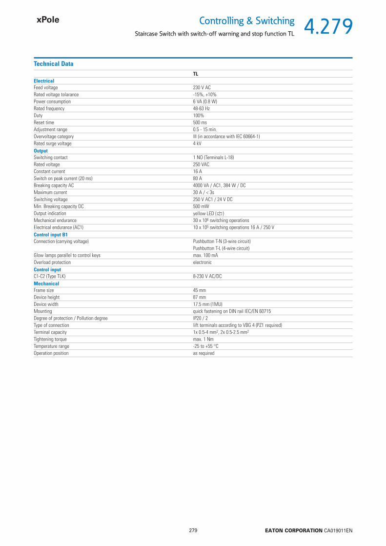
4.279
279 EATON CORPORATION CA019011EN
Controlling & SwitchingStaircase Switch with switch-off warning and stop function TL
Technical DataTL
ElectricalFeed voltage 230 V ACRated voltage tolarance -15%, +10%Power consumption 6 VA (0.8 W)Rated frequency 48-63 HzDuty 100%Reset time 500 msAdjustment range 0.5 - 15 min.Overvoltage category III (in accordance with IEC 60664-1)Rated surge voltage 4 kVOutputSwitching contact 1 NO (Terminals L-18)Rated voltage 250 VACConstant current 16 ASwitch on peak current (20 ms) 80 ABreaking capacity AC 4000 VA / AC1, 384 W / DCMaximum current 30 A / < 3sSwitching voltage 250 V AC1 / 24 V DCMin. Breaking capacity DC 500 mWOutput indication yellow LED ( )Mechanical endurance 30 x 106 switching operationsElectrical endurance (AC1) 10 x 105 switching operations 16 A / 250 VControl input B1Connection (carrying voltage) Pushbutton T-N (3-wire circuit)
Pushbutton T-L (4-wire circuit)Glow lamps parallel to control keys max. 100 mAOverload protection electronicControl inputC1-C2 (Type TLK) 8-230 V AC/DCMechanicalFrame size 45 mmDevice height 87 mmDevice width 17.5 mm (1MU)Mounting quick fastening on DIN rail IEC/EN 60715Degree of protection / Pollution degree IP20 / 2Type of connection lift terminals according to VBG 4 (PZ1 required)Terminal capacity 1x 0.5-4 mm2, 2x 0.5-2.5 mm2
Tightening torque max. 1 NmTemperature range -25 to +55 °COperation position as required
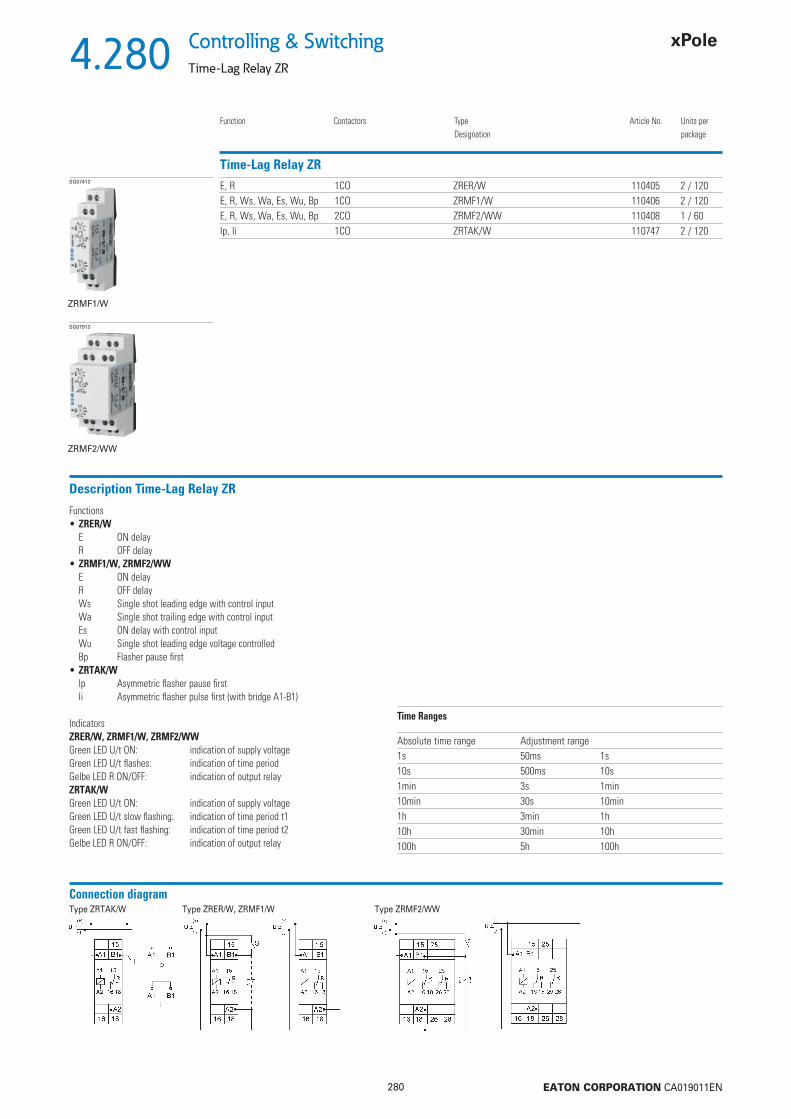
4.280
280 EATON CORPORATION CA019011EN
Controlling & Switching
Time-Lag Relay ZR
Time-Lag Relay ZR
Function Contactors TypeDesignation
Article No. Units perpackage
SG07412 E, R 1CO ZRER/W 110405 2 / 120E, R, Ws, Wa, Es, Wu, Bp 1CO ZRMF1/W 110406 2 / 120E, R, Ws, Wa, Es, Wu, Bp 2CO ZRMF2/WW 110408 1 / 60lp, li 1CO ZRTAK/W 110747 2 / 120
ZRMF1/W
SG07912
ZRMF2/WW
Description Time-Lag Relay ZR
Functions• ZRER/W
E ON delayR OFF delay
• ZRMF1/W, ZRMF2/WWE ON delayR OFF delayWs Single shot leading edge with control inputWa Single shot trailing edge with control inputEs ON delay with control inputWu Single shot leading edge voltage controlledBp Flasher pause fi rst
• ZRTAK/Wlp Asymmetric fl asher pause fi rstli Asymmetric fl asher pulse fi rst (with bridge A1-B1)
IndicatorsZRER/W, ZRMF1/W, ZRMF2/WW Green LED U/t ON: indication of supply voltageGreen LED U/t fl ashes: indication of time period Gelbe LED R ON/OFF: indication of output relayZRTAK/W Green LED U/t ON: indication of supply voltageGreen LED U/t slow fl ashing: indication of time period t1 Green LED U/t fast fl ashing: indication of time period t2 Gelbe LED R ON/OFF: indication of output relay
Connection diagramType ZRTAK/W Type ZRER/W, ZRMF1/W Type ZRMF2/WW
Time Ranges
Absolute time range Adjustment range1s 50ms 1s10s 500ms 10s1min 3s 1min10min 30s 10min1h 3min 1h10h 30min 10h100h 5h 100h
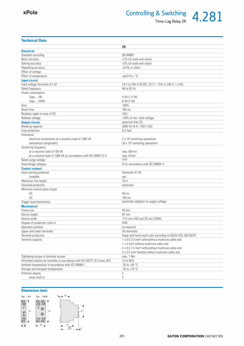
4.281
281 EATON CORPORATION CA019011EN
Controlling & SwitchingTime-Lag Relay ZR
Technical DataZR
ElectricalStandard according EN 60669Basic accuracy ±1% (of scale end value)Setting accuracy <5% (of scale end value)Repeating accuracy: <0.5% or ±5msEffect of voltage –Effect of temperature 0.01% / °CInput circuitFeed voltage Terminals A1-A2 24 V to 240 V AC/DC, 24 V / -15% to 240 V / +10%Rated frequency 48 to 63 HzPower consumption
Type: .../W 4 VA (1.5 W)Type: .../WW 6 VA (2 W)
Duty 100%Reset time 100 msResidual ripple in case of DC 10%Release voltage >30% of min. feed voltageOutput circuit potential-free COBreaking capacity 2000 VA (8 A / 250 V AC)Fuse protection 8 A fastEndurance
electrical components at a resistive load of 1000 VA 2 x 10⁵ switching operationsmechanical components 20 x 106 switching operations
Switching frequencyat a resistive load of 100 VA max. 60/minat a resistive load of 1000 VA (in accordance with IEC 60947-5-1) max. 6/min
Rated surge voltage 4 kVOvervoltage category III (in accordance with IEC 60664-1)Control contactInput carrying potential Terminals A1-B1
loadable yesMaximum line length 10 mOverload protection electronicMinimum control pulse length
DC 50 msAC 100 ms
Trigger level (sensitivity) automatic adaption to supply voltageMechanicalFrame size 45 mmDevice height 87 mmDevice width 17.5 mm (/W) and 35 mm (/WW)Degree of protection, built-in IP40Operation position as requiredUpper and lower terminals lift terminalsTerminal protection fi nger and hand touch safe according to DGUV VS3, EN 50274Terminal capacity 1 x 0.5-2.5 mm2 with/without multicore cable end
1 x 4 mm2 without multicore cable end2 x 0.5-1.5 mm2 with/without multicore cable end2 x 2.5 mm2 fl exible without multicore cable end
Tightening torque of terminal screws max. 1 NmPermitted relative air humidity in accordance with IEC 60721-3-3 class 3K3 15 to 85%Ambient temperature in accordance with IEC 60068-1 -25 to +55 °CStorage and transport temperature -25 to +70 °CPollution degree 2
when built in 3
Dimensions (mm)

4.282
282 EATON CORPORATION CA019011EN
Controlling & Switching
Time-Lag Relay ZR
Description of Functions
• ON delay (E)When the supply voltage U is applied, the set interval t begins (green LED U/t fl ashes). After the interval t has expired (green LED U/t illuminated) the output relay R switches into on-position (yellow LED illuminated) This status remains until the supply voltage is interrupted. If the supply voltage is inter-rupted be fore the expiry of the interval t, the interval already expired is erased and is restarted when the supply voltage is next applied.
• OFF delay (R)The supply voltage U must be constantly applied to the device (green LED U/t illuminated) When the control contact S is closed, the output relay R switch-es into on-position (yellow LED illuminated). If the control contact is opened, the set interval t begins (green LED fl ashes) After the interval t has expired (green LED U/t illuminated) the output relay switches into off-position (yellow LED not illuminated) If the control contact is closed again before the interval t has expired, the interval already expired is erased and is restarted.
• Single shot leading edge with control input (Ws)The supply voltage U must be constantly applied to the device (green LED U/t illuminated). When the control contact S is closed, the output relay R switches into on-position (green LED U/t illuminated) and the set interval t begins (green LED U/t fl ashes). After the interval t has expired (green LED U/t illuminated) the output relay switches into off-position (yellow LED not illuminated). During the interval, the control contact can be operated any number of times. A further cycle can only be started when the cycle run has been completed.
• Single shot trailing edge with control input (Wa)The supply voltage U must be constantly applied to the device (green LED U/t illuminated). Closing the control contact S has no infl uence on the condi-tion of the output R. When the control contact is opened, the output relay switches into on-position (yellow LED illuminated) and the set interval t begins (green LED U/t fl ashes). After the interval t has expired (green LED U/t illuminated), the output relay switches into off-position (yellow LED not illumi-nated). During the interval, the control contact can be operated any number of times. A further cycle can only be started when the cycle run has been completed.
• ON delay with control input (Es)The supply voltage U must be constantly applied to the device (green LED U/t illuminated). When the control contact S is closed, the set interval t begins (green LED U/t fl ashes). After the interval t has expired (green LED U/t illuminated) the output relay R switches into on-position (yellow LED illuminated). This status remains until the control contact is opened again If the control contact is opened before the interval t has expired , the interval already expired is erased and is restarted with the next cycle.
• Single shot leading edge voltage controlled (Wu)When the supply voltage U is applied, the output relay R switches into on-position (yellow LED illuminated) and the set interval t begins (green LED U/t fl ashes). After the interval t has expired (green LED U/t illuminated) the output relay switches into off-position (yellow LED not illuminated). This status remains until the supply voltage is interrupted. If the supply voltage is interrupted before the interval t has expired. The output relay switches into off-position The interval already is erased and is restarted when the supply voltage is next applied.
• Flasher pause fi rst (Bp)When the supply voltage U is applied, the set interval t begins (green LED U/t fl ashes). After the interval t has expired, the output relay R switches into on-position (yellow LED illuminated) and the set interval t begins again. After the interval t has expired. the output relay switches into off-position (yellow LED not illuminated). The output relay is triggered at a ratio of 1:1 until the supply voltage is interrupted.
• Asymmetric fl asher pause fi rst (lp)When the supply voltage U is applied, the set interval t1 begins (green LED U/t fl ashes slowly) After the interval t1 has expired. the output relay R switch-es into on-position (yellow LED illuminated) and the set interval t2 begins (green LED U/t fl ashes fast). After the interval t2 has expired, the output relay switches into off-position (yellow LED not illuminated). The output relay is triggered at the ratio of t1:t2 until the supply voltage is interrupted.
• Asymmetric fl asher pulse fi rst (li)When the supply voltage U is applied, the output relay R switches into on-position (yellow LED illuminated) and the set interval t1 begins (green LED U/t fl ashes slowly). After the interval t1 has expired, the output relay switches into off-position (yellow LED not illuminated) and the set interval t2 begins (green LED U/t fl ashes fast). After the interval t2 has expired, the output relay switches into on-position (yellow LED illuminated). The output relay is trig-gered at the ratio of t1:t2 until the supply voltage is interrupted.
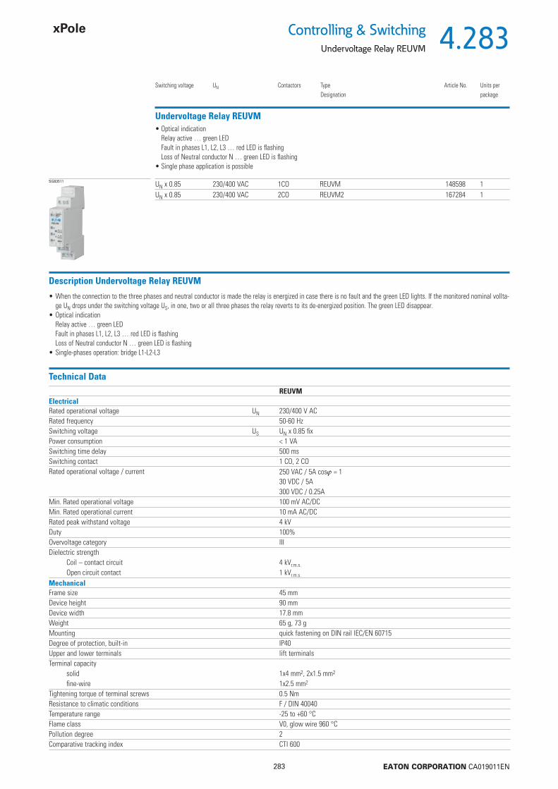
4.283
283 EATON CORPORATION CA019011EN
Controlling & SwitchingUndervoltage Relay REUVM
Undervoltage Relay REUVM
Switching voltage UN Contactors TypeDesignation
Article No. Units perpackage
SG83511 UN x 0.85 230/400 VAC 1CO REUVM 148598 1UN x 0.85 230/400 VAC 2CO REUVM2 167284 1
• Optical indicationRelay active … green LEDFault in phases L1, L2, L3 … red LED is fl ashingLoss of Neutral conductor N … green LED is fl ashing
• Single phase application is possible
Description Undervoltage Relay REUVM
• When the connection to the three phases and neutral conductor is made the relay is energized in case there is no fault and the green LED lights. If the monitored nominal vollta-ge UN drops under the switching voltage US, in one, two or all three phases the relay reverts to its de-energized position. The green LED disappear.
• Optical indicationRelay active … green LEDFault in phases L1, L2, L3 … red LED is fl ashingLoss of Neutral conductor N … green LED is fl ashing
• Single-phases operation: bridge L1-L2-L3
Technical DataREUVM
ElectricalRated operational voltage UN 230/400 V ACRated frequency 50-60 HzSwitching voltage US UN x 0.85 fi xPower consumption < 1 VASwitching time delay 500 msSwitching contact 1 CO, 2 CORated operational voltage / current 250 VAC / 5A cos = 1
30 VDC / 5A300 VDC / 0.25A
Min. Rated operational voltage 100 mV AC/DCMin. Rated operational current 10 mA AC/DCRated peak withstand voltage 4 kVDuty 100%Overvoltage category IIIDielectric strength
Coil – contact circuit 4 kVr.m.s.
Open circuit contact 1 kVr.m.s.
MechanicalFrame size 45 mmDevice height 90 mmDevice width 17.8 mmWeight 65 g, 73 gMounting quick fastening on DIN rail IEC/EN 60715Degree of protection, built-in IP40Upper and lower terminals lift terminalsTerminal capacity
solid 1x4 mm2, 2x1.5 mm2
fi ne-wire 1x2.5 mm2
Tightening torque of terminal screws 0.5 NmResistance to climatic conditions F / DIN 40040Temperature range -25 to +60 °CFlame class V0, glow wire 960 °CPollution degree 2Comparative tracking index CTI 600
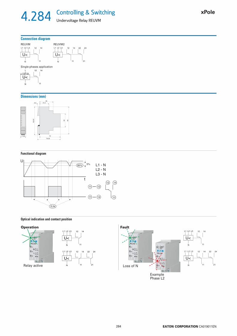
4.284
284 EATON CORPORATION CA019011EN
Controlling & Switching
Undervoltage Relay REUVM
REUVM REUVM2
12 14
11
L3L2L1
N
U<
L
Single-phases application
Connection diagram
Dimensions (mm)
Functional diagram
Optical indication and contact position
12 14
11
L3L2L1
N
U<
Operation
12 14
11
L3L2L1
N
U<
22 24
21Relay active
Fault
Loss of N
Example Phase L2

4.285
285 EATON CORPORATION CA019011EN
Controlling & SwitchingVoltage Indication UVA
Voltage Indication UVA
Rated operational voltage TypeDesignation
Article No. Units perpackage
SG00112 230/400 V AC, 50/60 Hz UVA 167285 1
• Optical indicationVoltage of phases L1, L2, L3 is indicated with green LED‘s even at loss of Neutral conductor N
• Single-phases application, or even possible to use DC
Description Voltage Indication UVA
• When the connection to the three phases and neutral conductor is made, the green Power LED lights. If only two phases are connected, eg. L1 and L3, only these green LED`s lights, even at loss of Neutral conductor N.
• For use as voltage return indication in manual operated Mains-Emergency-system operation• Large operational voltage range 85-480 V AC, 85-300 V DC
Technical DataUVA
ElectricalRated operational voltage UN 230/400 V ACRated frequency 50-60 HzRated operational voltage range
L-L 85-480 V ACL-N 85-300 V AC/DC
Power consumption at 400 V AC 3x 23 mWMax. permissible back-up fuse 16A gG (gL)Duty 100%Rated peak withstand voltage 6 kVOvervoltage category IVMechanicalFrame size 45 mmDevice height 90 mmDevice width 17.8 mmWeight 42 gMounting quick fastening on DIN rail IEC/EN 60715Degree of protection, built-in IP40Upper and lower terminals lift terminalsTerminal capacity
solid 1x4 mm2, 2x1.5 mm2
fi ne-wire 1x2.5 mm2
Tightening torque of terminal screws 0.5 NmTemperature range -30 to +60°CFlame class V0, glow wire 960 °CPollution degree 2Comparative tracking index CTI 600
Connection diagram
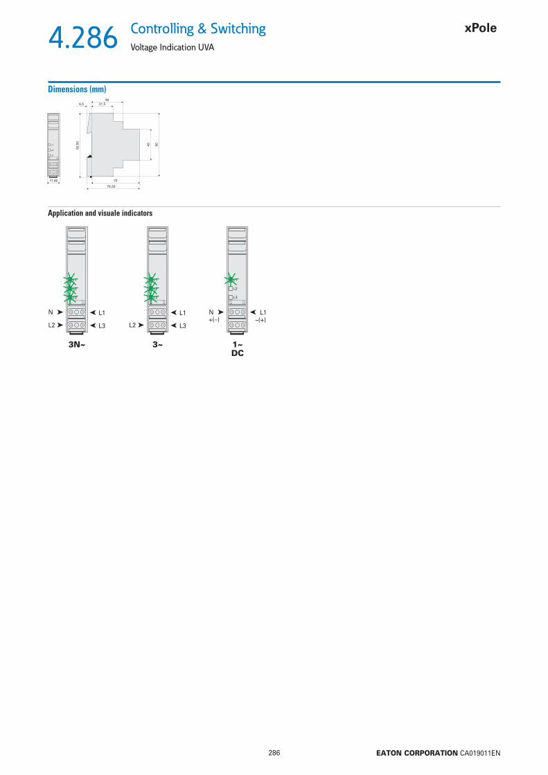
4.286
286 EATON CORPORATION CA019011EN
Controlling & Switching
Voltage Indication UVA
Dimensions (mm)
3N~ 3~
Application and visuale indicators
L1
N
L3
L2
L1
L3
L2
N
1~DC
–(+)+(–)L1

4.287
287 EATON CORPORATION CA019011EN
Controlling & SwitchingLoad Shedding (Current) Relay Z-LAR
Load Shedding (Current) Relay Z-LAR
Function Rated operational current range(A)
TypeDesignation
Article No. Units perpackage
SG78711 NC 3-8 Z-LAR/8-O 248256 1 / 60NC 10-16 Z-LAR/16-O 248257 1 / 60NC 15-32 Z-LAR/32-O 248258 1 / 60NO 3-8 Z-LAR/8-S 248259 1 / 60NO 10-16 Z-LAR/16-S 248260 1 / 60NO 15-32 Z-LAR/32-S 248261 1 / 60CO 3-8 Z-LAR/8-W 248262 1 / 60
Description Load Shedding (Current) Relay Z-LAR
• For simple priority connection of important consumers• For fast current increase• Expensive peak loads are avoided effi ciently (staggered heating)• Integrated auxiliary switch, 1 NC or 1 NO or 1 CO contact• NC and NO contact are potential free
Technical DataZ-LAR/8 Z-LAR/16 Z-LAR/32
ElectricalNominal thermal current Ith 8 A 16 A 32 ARated voltage U 250 V AC 250 V AC 250 V ACResponding current IAN 3 A 10 A 15 ARelease current IA 1.8 A 4.2 A 7.4 AMax. electrical switching frequency 3600/h 3600/h 3600/hRated insulation voltage Ui 440 V 440 V 440 VPower loss at Ith
Effective power 3.4 W 1.95 W 3.17 WApparent power 7.7 VA 4.66 VA 7,36 VA
Rated peak withstand voltage Uimp 4 kV 4 kV 4 kVBack-up fuse line protection max. 10 A max. 16 A max. 32 ASwitching contact
Function NC, NO, COBack-up fuse max. 1 A gL max. 1 A gL max. 1 A gLContact gap *) < 3 mm (μ) < 3 mm (μ) < 3 mm (μ)Breaking capacity 1 A / 250 V~ 1 A / 250 V~ 1 A / 250 V~Minimum switching capacity 300 mW 300 mW 300 mWMinimum operational voltage 12 V 12 V 12 V
Endurance electrical components 100,000 switching operations*) Do not use as the only means of isolating a device from the line voltageMechanicalFrame size 45 mm 45 mm 45 mmDevice height 80 mm 80 mm 80 mmDevice width 17.5 mm (1MU) 17.5 mm (1MU) 17.5 mm (1MU)Mounting quick fastening on DIN rail IEC/EN 60715Degree of protection, built-in IP40 IP40 IP40Terminal protection fi nger and hand touch safe according to DGUV VS3, EN 50274Upper and lower terminals lift terminals lift terminals lift terminalsTerminal capacity
Main circuit 2 x 10 mm2 2 x 10 mm2 2 x 10 mm2
Auxiliary circuit 2 x 2.5 mm2 2 x 2.5 mm2 2 x 2.5 mm2
Tightening torque of terminal screwsMain circuit max. 2.4 Nm max. 2.4 Nm max. 2.4 NmAuxiliary circuit max. 1 Nm max. 1 Nm max. 1 Nm
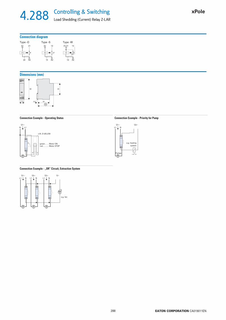
4.288
288 EATON CORPORATION CA019011EN
Controlling & Switching
Load Shedding (Current) Relay Z-LAR
Connection diagramType -O Type -S Type -W
Dimensions (mm)
Connection Example - Operating Status Connection Example - Priority for Pump
Connection Example - „OR“ Circuit, Extraction System
green . . . . Motor ONred . . . . . . Motor STOP
e.g. heating system
e.g. fan
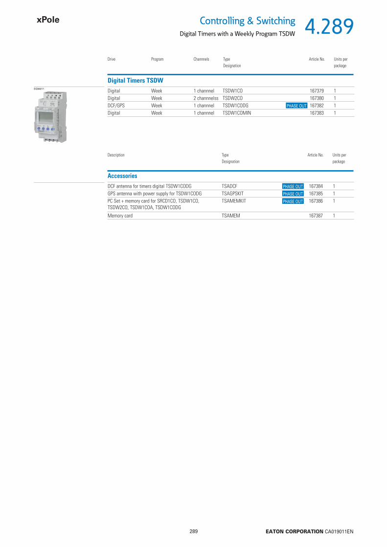
4.289
289 EATON CORPORATION CA019011EN
Controlling & SwitchingDigital Timers with a Weekly Program TSDW
Digital Timers TSDW
Drive Program Channnels TypeDesignation
Article No. Units perpackage
SG84011 Digital Week 1 channnel TSDW1CO 167379 1Digital Week 2 channnelss TSDW2CO 167380 1DCF/GPS Week 1 channnel TSDW1CODG 167382 1Digital Week 1 channnel TSDW1COMIN 167383 1
Accessories DCF antenna for timers digital TSDW1CODG TSADCF 167384 1
GPS antenna with power supply for TSDW1CODG TSAGPSKIT 167385 1PC Set + memory card for SRCD1CO, TSDW1CO, TSDW2CO, TSDW1COA, TSDW1CODG
TSAMEMKIT 167386 1
Memory card TSAMEM 167387 1
Description TypeDesignation
Article No. Units perpackage
PHASE OUT
PHASE OUT
PHASE OUT
PHASE OUT
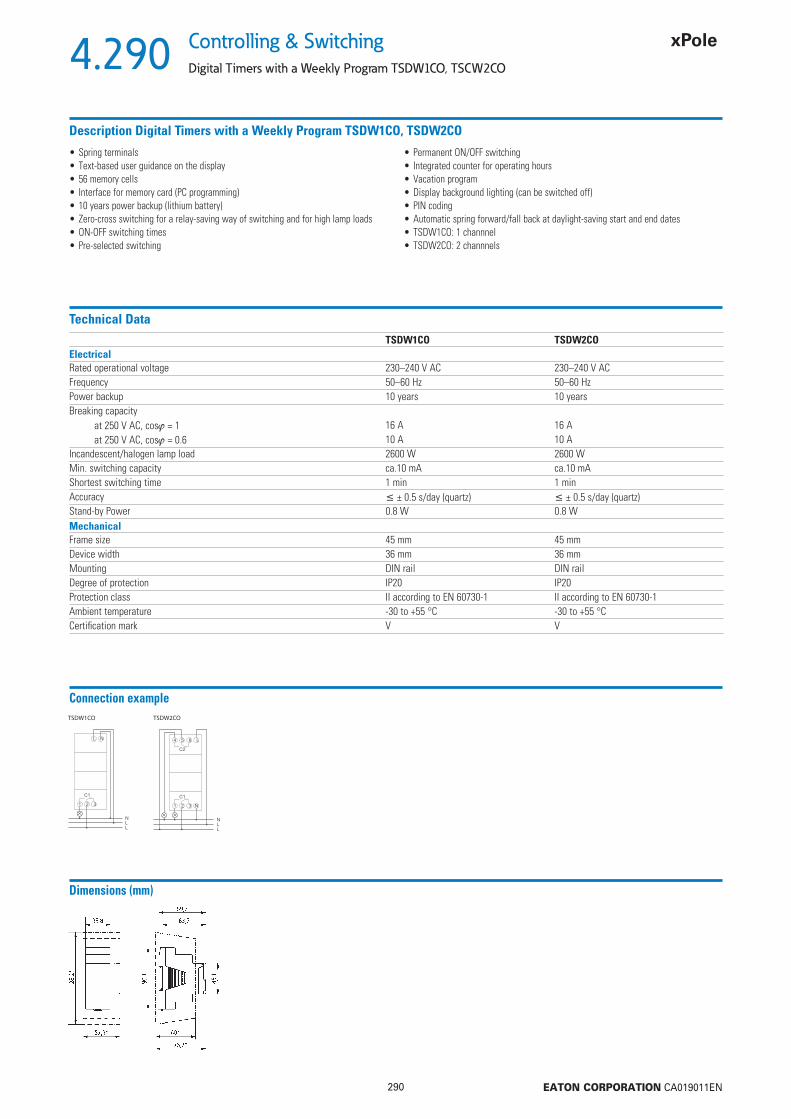
4.290
290 EATON CORPORATION CA019011EN
Controlling & Switching
Digital Timers with a Weekly Program TSDW1CO, TSCW2CO
Connection example
Dimensions (mm)
Description Digital Timers with a Weekly Program TSDW1CO, TSDW2CO
• Spring terminals• Text-based user guidance on the display• 56 memory cells• Interface for memory card (PC programming)• 10 years power backup (lithium battery)• Zero-cross switching for a relay-saving way of switching and for high lamp loads• ON-OFF switching times• Pre-selected switching
• Permanent ON/OFF switching• Integrated counter for operating hours• Vacation program• Display background lighting (can be switched off)• PIN coding• Automatic spring forward/fall back at daylight-saving start and end dates• TSDW1CO: 1 channnel• TSDW2CO: 2 channnels
Technical DataTSDW1CO TSDW2CO
ElectricalRated operational voltage 230–240 V AC 230–240 V ACFrequency 50–60 Hz 50–60 HzPower backup 10 years 10 yearsBreaking capacity
at 250 V AC, cos = 1 16 A 16 Aat 250 V AC, cos = 0.6 10 A 10 A
Incandescent/halogen lamp load 2600 W 2600 WMin. switching capacity ca.10 mA ca.10 mAShortest switching time 1 min 1 minAccuracy ± 0.5 s/day (quartz) ± 0.5 s/day (quartz)Stand-by Power 0.8 W 0.8 WMechanicalFrame size 45 mm 45 mmDevice width 36 mm 36 mmMounting DIN rail DIN railDegree of protection IP20 IP20Protection class II according to EN 60730-1 II according to EN 60730-1Ambient temperature -30 to +55 °C -30 to +55 °CCertifi cation mark V V
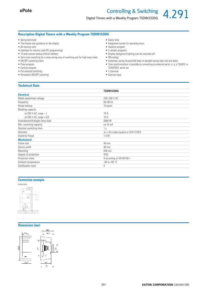
4.291
291 EATON CORPORATION CA019011EN
Controlling & SwitchingDigital Timers with a Weekly Program TSDW1CODG
Description Digital Timers with a Weekly Program TSDW1CODG
• Spring terminals• Text-based user guidance on the display• 84 memory cells• Interface for memory card (PC programming)• 10 years power backup (lithium battery)• Zero-cross switching for a relay-saving way of switching and for high lamp loads• ON-OFF switching times• Pulse program• Cyclical program• Pre-selected switching• Permanent ON/OFF switching
• Expiry timer• Integrated counter for operating hours• Vacation program• 2 random programs• Display background lighting (can be switched off)• PIN coding• Automatic spring forward/fall back at daylight-saving start and end dates• Time synchronization is possible by connecting an external aerial, e. g. a TSADCF or
TSAGPSKIT aerial set• 1 channnel• External input
Technical DataTSDW1CODG
ElectricalRated operational voltage 230–240 V ACFrequency 50–60 HzPower backup 10 yearsBreaking capacity
at 250 V AC, cos = 1 16 Aat 250 V AC, cos = 0.6 10 A
Incandescent/halogen lamp load 2600 WMin. switching capacity ca.10 mAShortest switching time 1 sAccuracy ± 0.5 s/day (quartz) or DCF77/GPSStand-by Power 1.4 WMechanicalFrame size 45 mmDevice width 36 mmMounting DIN railDegree of protection IP20Protection class II according to EN 60730-1Ambient temperature -30 to +55 °CCertifi cation mark V
Connection example
Dimensions (mm)
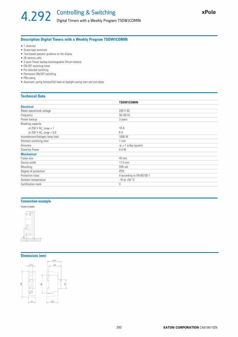
4.292
292 EATON CORPORATION CA019011EN
Controlling & Switching
Digital Timers with a Weekly Program TSDW1COMIN
Description Digital Timers with a Weekly Program TSDW1COMIN
• 1 channnel• Screw-type terminals• Text-based operator guidance on the display• 28 memory cells• 3 years Power backup (exchangeable lithium battery)• ON-OFF switching times• Pre-selected switching• Permanent ON/OFF switching• PIN coding• Automatic spring forward/fall back at daylight-saving start and end dates
Technical DataTSDW1COMIN
ElectricalRated operational voltage 230 V ACFrequency 50–60 HzPower backup 3 yearsBreaking capacity
at 250 V AC, cos = 1 16 Aat 250 V AC, cos = 0.6 6 A
Incandescent/halogen lamp load 1000 WShortest switching time 1 minAccuracy ± 1 s/day (quartz)Stand-by Power 0.4 WMechanicalFrame size 45 mmDevice width 17.5 mmMounting DIN railDegree of protection IP20Protection class II according to EN 60730-1Ambient temperature -10 to +55 °CCertifi cation mark V
Connection example
Dimensions (mm)

4.293
293 EATON CORPORATION CA019011EN
Controlling & SwitchingAstronomical Timer with a Weekly Program TSDW1COA
Astronomical Timer with a Weekly Program TSDW1COA
Drive Program Channnels TypeDesignation
Article No. Units perpackage
SG84011 Quartz Week 1 channnel TSDW1COA 167381 1
Description Astronomical Timer with a Weekly Program TSDW1COA
• Astronomical switching function (automatic calculation of sunrise and sunset times for the entire year)
• Spring terminals• Text-based user guidance on the display• Interface for memory card (PC programming)• 10 years power backup (lithium battery)• Zero-cross switching for a relay-saving way of switching and for high lamp loads• Calculated astronomical switching times• Programmable ON/OFF switching times
• Pre-selected switching• Permanent ON/OFF switching• Integrated counter for operating hours• Vacation program• Display background lighting (can be switched off)• PIN coding• Automatic spring forward/fall back at daylight-saving start and end dates• 1 channnel• 54 memory cells
Technical DataTSDW1COA
ElectricalRated operational voltage 230–240 V ACFrequency 50–60 HzPower backup 10 yearsBreaking capacity
at 250 V AC, cos = 1 16 Aat 250 V AC, cos = 0.6 10 A
Incandescent/halogen lamp load 2600 WMin. switching capacity ca.10 mAShortest switching time 1 sAccuracy ± 0.5 s/day (quartz)Stand-by Power 0.8 WMechanicalFrame size 45 mmDevice width 36 mmMounting DIN railDegree of protection IP20Protection class II according to EN 60730-1Ambient temperature -30 to +55 °CCertifi cation mark V
Connection example Dimensions (mm)

4.294
294 EATON CORPORATION CA019011EN
Controlling & Switching
Analogue Timers TS
Analogue Timers TS
Drive Program Channnels TypeDesignation
Article No. Units perpackage
SG83911 Quartz Day 1 channnel TSQD1NO 167388 1Synchron Day 1 channnel TSSD1NO 167389 1Quartz Day 1 channnel TSQD1CO 167390 1Synchron Day 1 channnel TSSD1CO 167391 1Quartz Week 1 channnel TSQW1CO 167392 1
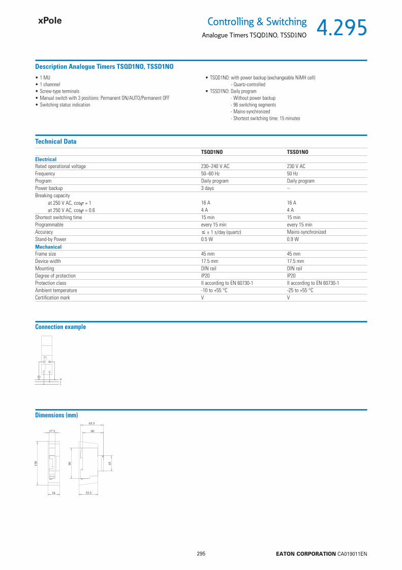
4.295
295 EATON CORPORATION CA019011EN
Controlling & SwitchingAnalogue Timers TSQD1NO, TSSD1NO
Description Analogue Timers TSQD1NO, TSSD1NO
• 1 MU• 1 channnel• Screw-type terminals• Manual switch with 3 positions: Permanent ON/AUTO/Permanent OFF• Switching status indication
• TSQD1NO: with power backup (exchangeable NiMH cell)- Quartz-controlled
• TSSD1NO: Daily program- Without power backup- 96 switching segments- Mains-synchronized- Shortest switching time: 15 minutes
Technical DataTSQD1NO TSSD1NO
ElectricalRated operational voltage 230–240 V AC 230 V ACFrequency 50–60 Hz 50 HzProgram Daily program Daily programPower backup 3 days –Breaking capacity
at 250 V AC, cos = 1 16 A 16 Aat 250 V AC, cos = 0.6 4 A 4 A
Shortest switching time 15 min 15 minProgrammable every 15 min every 15 minAccuracy ± 1 s/day (quartz) Mains-synchronizedStand-by Power 0.5 W 0.9 WMechanicalFrame size 45 mm 45 mmDevice width 17.5 mm 17.5 mmMounting DIN rail DIN railDegree of protection IP20 IP20Protection class II according to EN 60730-1 II according to EN 60730-1Ambient temperature -10 to +55 °C -25 to +55 °CCertifi cation mark V V
Connection example
Dimensions (mm)

4.296
296 EATON CORPORATION CA019011EN
Controlling & Switching
Analogue Timers TSQD1CO, TSSD1CO, TSQW1CO
Description Analogue Timers TSQD1CO, TSSD1CO, TSQW1CO
• 3 MU• 1 channnel• Spring terminals• Pre-selected switching• Manual switch with 3 positions: Permanent ON/AUTO/Permanent OFF• Switching status indication• TSQD1CO:
- With power backup (NiMH cell)- Quartz-controlled- Clock-hands for time indication and 12h/24h recognition- Easy correction of spring forward/fall back at daylight-saving start and end
• TSQW1CO: - Weekly program- 84 switching segments- Shortest switching time: 2 hours
• TSSD1CO: - Daily program- Without power backup- 96 switching segments- Shortest switching time: 15 minutes- Clock-hands for time indication and 12h/24h recognition- Easy correction of spring forward/fall back at daylight-saving start and end
Technical DataTSQD1CO TSSD1CO TSQW1CO
ElectricalRated operational voltage 110–230 V AC 110–230 V AC 110–230 V ACFrequency 50–60 Hz 50 Hz 50–60 HzProgram Daily program Daily program Weekly programPower backup 200 hours, approx. 100 hours
at 110 V– 200 hours, approx. 100 hours
at 110 VBreaking capacity
at 250 V AC, cos = 1 16 A 16 A 16 Aat 250 V AC, cos = 0.6 4 A 4 A 4 A
Shortest switching time 15 min 15 min 2 hProgrammable every 15 min every 15 min alle 2 hAccuracy ± 1 s/day (quartz) Mains-synchronized ± 1 s/day (quartz)Stand-by Power 0.5 W 0.9 W 0.5 WMechanicalFrame size 45 mm 45 mm 45 mmDevice width 52.5+1.5 mm 52.5+1.5 mm 52.5+1.5 mmMounting DIN rail DIN rail DIN railDegree of protection IP20 IP20 IP20Protection class II according to EN 60730-1 II according to EN 60730-1 II according to EN 60730-1Ambient temperature -20 to +55 °C -20 to +55 °C -20 to +55 °CCertifi cation mark V V V
Connection example
Dimensions (mm)
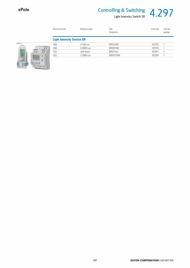
4.297
297 EATON CORPORATION CA019011EN
Controlling & SwitchingLight Intensity Switch SR
Light Intensity Switch SR
Switching contact Brightness range TypeDesignation
Article No. Units perpackage
SG84111 1NO 2-100 Lux SRSD1NO 167375 11NO 2-2000 Lux SRSW1NO 167376 11CO with timer SRCD1CO 167377 11CO 2-2000 Lux SRSD1COW 167378 1

4.298
298 EATON CORPORATION CA019011EN
Controlling & Switching
Light Intensity Switch analog for DIN rail SRSD1NO, SRSD1COW
Description Light Intensity Switch analog for DIN rail SRSD1NO, SRSD1COW
• Analog twilight switch• External surface-mounted light sensor is incl. in the scope of delivery• Indication of the channel and switching status• Brightness level can be continuously adjusted
• SRSD1NO: Fixed switch-on and switch-off delay• SRSD1COW: Variable switch-on and switch-off delay
- Spring terminals- Expanded brightness range and variable delay time- Five adjustable brightness ranges for easy setting of the lux value
- Permanent OFF and permanent ON function can be set at the potentiometer - Test function
Technical DataSRSD1NO SRSD1COW
ElectricalRated operational voltage 220–240 V AC 220–240 V ACFrequency 50–60 Hz 50 HzSetting range for brightness 2–100 lx 2-2000 lxSwitch-on delay 20 s 60 sSwitch-off delay 80 s 60 sContact type NO COSwitch output Potential-free Potential-free, not suitable for SELVBreaking capacity
at 250 V AC, cos = 1 16 A 16 Awith fl uorescent lamp load 10 AX 10 AX
Min. switching capacity – <10 mAIncandescent lamp load 2300 W 2300 WFluorescent lamp load (VVG - low-loss ballast) non-compensated/series-compensated/duo switching 2300 VA 2300 VAEnergy saving lamps 9 x 7 W, 7 x 11 W, 34 x 7 W, 27 x 11 W,
7 x 15 W, 7 x 20 W, 24 x 15 W, 22 x 23 W7 x 23 W
Stand-by Power 0.8 W 1.3 WMechanicalFrame size 45 mm 45 mmDevice width 17.5 mm 54 mmMounting DIN rail DIN railProtection class II IIAmbient temperature -25 to +50 °C -30 to +55 °CCertifi cation mark V VMax. line length to the sensor 25 m 100 m
Connection diagramSRSD1NO SRSD1COW
Dimensions (mm)SRSD1NO SRSD1COW
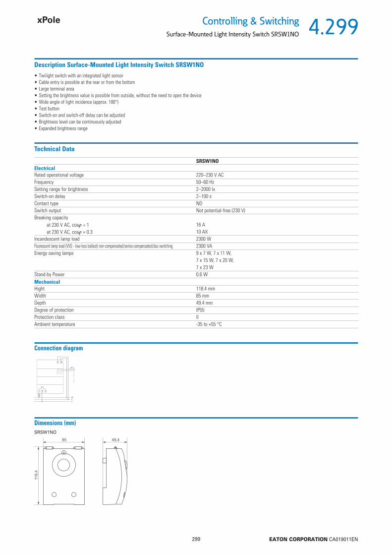
4.299
299 EATON CORPORATION CA019011EN
Controlling & SwitchingSurface-Mounted Light Intensity Switch SRSW1NO
Description Surface-Mounted Light Intensity Switch SRSW1NO
• Twilight switch with an integrated light sensor• Cable entry is possible at the rear or from the bottom• Large terminal area• Setting the brightness value is possible from outside, without the need to open the device • Wide angle of light incidence (approx. 180°)• Test button• Switch-on and switch-off delay can be adjusted• Brightness level can be continuously adjusted • Expanded brightness range
Technical Data
SRSW1NOElectricalRated operational voltage 220–230 V ACFrequency 50–60 HzSetting range for brightness 2–2000 lxSwitch-on delay 2–100 sContact type NOSwitch output Not potential-free (230 V)Breaking capacity
at 230 V AC, cos = 1 16 Aat 230 V AC, cos = 0.3 10 AX
Incandescent lamp load 2300 WFluorescent lamp load (VVG - low-loss ballast) non-compensated/series-compensated/duo switching 2300 VAEnergy saving lamps 9 x 7 W, 7 x 11 W,
7 x 15 W, 7 x 20 W, 7 x 23 W
Stand-by Power 0.6 WMechanicalHight 118.4 mmWidth 85 mmDepth 49.4 mmDegree of protection IP55Protection class IIAmbient temperature -35 to +55 °C
Connection diagram
Dimensions (mm)SRSW1NO

4.300
300 EATON CORPORATION CA019011EN
Controlling & Switching
Light Intensity Switch with Timer for DIN Rail SRCD1CO
Description Light Intensity Switch with Timer for DIN Rail SRCD1CO
• Twilight switch with an integrated weekly timer • Adjustable switch-on and switch-off delay • Brightness levels and switching-delay can separately be set for switch-on and
switch-off • Fixed times for ON and OFF (e.g. interruption during the night)• DuoFix spring terminals • Zero-cross switching to protect the relay contact and the lamp so as to increase
their service life• Interface for the OBELISK top2 memory card (PC programming)• Light sensor included in the scope of delivery • Permanent ON/OFF switching• Test function• Pre-selected switching
• Display background lighting• PIN coding • Counter for operating hours • Display of the channel and switching status• Vacation and holiday program with annual function for fi xed date and variable date
holidays (e.g. the ones that depend on Easter)• Different rules can be selected for daylight-saving start and end or they can be free-
ly selected • For type SRCD1CO: - Analog twilight switch - 1 Channel - Analog setting of brightness levels
Technical Data
SRCD1COElectricalRated operational voltage 220–240 V ACFrequency 50–60 HzSetting range for brightness 2–2000 lxSwitch-on delay 0–59 minContact type COSwitch output Potential-free, not suitable for SELVBreaking capacity
at 250 V AC, cos = 1 16 Aat 250 V AC, cos = 0.6 10 Awith fl uorescent lamp load 10 AX
Incandescent lamp load 2600 WFluorescent lamp load (VVG - low-loss ballast) non-compensated/series-compensated/duo switching 2300 VAEnergy saving lamps 22 x 7 W, 18 x 11 W,
16 x 15 W, 16 x 20 W,14 x 23 W
Stand-by Power 1.3 WMechanicalFrame size 45 mmDevice width 72 mmMounting DIN railProtection class IIAmbient temperature -30 to +55 °CMax. line length to the sensor 100 m
Connection diagram
Dimensions (mm)
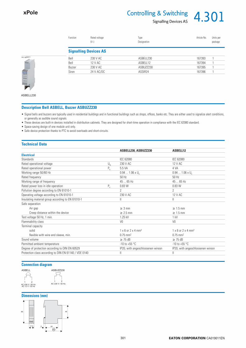
4.301
301 EATON CORPORATION CA019011EN
Controlling & SwitchingSignalling Devices AS
Function Rated voltage(V~)
TypeDesignation
Article No. Units perpackage
Bell 230 V AC ASBELL230 167393 1Bell 12 V AC ASBELL12 167394 1Buzzer 230 V AC ASBUZZ230 167395 1Siren 24 V AC/DC ASSIR24 167396 1
Signalling Devices ASwa_sg04311
ASBELL230
Technical DataASBELL230, ASBUZZ230 ASBELL12
ElectricalStandards IEC 62080 IEC 62080Rated operational voltage Ue 230 V AC 12 V ACRated operational power Ps 5.5 VA 4 VAWorking range 50/60 Hz 0.94 ... 1.06 x Uc 0.94 ... 1.06 x Uc
Rated frequency 50 Hz 50 HzWorking range of frequency 45 ... 65 Hz 45 ... 65 HzRated power loss in idle operation Pv 0.83 W 0.83 WPollution degree according to EN 61010-1 2 2Operating voltage according to EN 61010-1 230 V AC 12 V ACInsulating material group according to EN 61010-1 II IISafe separation
Air gap 3 mm 1.5 mmCreep distance within the device 2.5 mm 1.5 mm
Test voltage 50 Hz, 1 min. 1.25 kV 1 kVFlammability class V0 V0Terminal capacity
solid 1 x 6 or 2 x 4 mm2 1 x 6 or 2 x 4 mm2
fl exible with wire end sleeve, min. 0.75 mm2 0.75 mm2
Sound volume 75 dB 75 dBPermitted ambient temperature -10 to +55 °C -10 to +55 °CDegree of protection according to DIN EN 60529 IP20, with angeschlossenen wiresn IP20, with angeschlossenen wiresnProtection class according to DIN EN 61140 / VDE 0140 II II
Description Bell ASBELL, Buzzer ASBUZZ230
• Signal bells and buzzers are typically used in residential buildings and in functional buildings such as shops, offi ces, banks etc. They are either used to signalize alert conditions, or generally as audible sound signals.
• These devices are built-in devices installed in distribution cabinets. They are designed for short-time operation in compliance with the IEC 62080 standard.• Space-saving design of one module unit only. • Safe device protection thanks to PTC to avoid overloads and short-circuits.
Connection diagramASBELL ASBUZZ230
Dimensions (mm)

4.302
302 EATON CORPORATION CA019011EN
Controlling & Switching
Signalling Devices AS
Technical Data Siren ASSIR24ASSIR24
ElectricalData according to EN 60669-1Feed voltage 24 V AC/DCVoltage tolerance range ± 15%Power loss 2.4 VAVoltage test AC 2.5 kVSound volume 105 dBOperative temperature -10 to +55 °CStorage temperature -25 to +70 °CDegree of protection IP20
Dimensions (mm)

4.303
303 EATON CORPORATION CA019011EN
Controlling & SwitchingBell-Transformers 230 V, TR-G
MU Secondary voltage(V)
Secondary current(A)
TypeDesignation
Article No. Units perpackage
2 8 1 TR-G/8 272480 1 / 282 4-8-12 1-1-0.67 TR-G3/8 272481 1 / 282 8 1 TR-G/8-S 272482 1 / 282 4-8-12 2-2-1.5 TR-G3/18 272483 1 / 283 12-24 2-1 TR-G2/24 272484 1 / 20
Bell-Transformers 230 V, TR-GSG82911
Technical DataTR-G/8 TR-G3/8 TR-G/8-S TR-G3/18 TR-G2/24
Electrical
Nominal power 8 VA 8 VA 8 VA 18 VA 24 VARated supply voltage range 230-240 V AC 230-240 V AC 230-240 V AC 230-240 V AC 230-240 V AC
at terminals 5-8 5-8 5-8 5-8 5-8Rated frequency 50 Hz 50 Hz 50 Hz 50 Hz 50 HzNo-load current 25 mA 26 mA 25 mA 36 mA 24 mARated supply current 69 mA 58 mA 69 mA 72/124/138 mA 155/160 mAPrimary resistance 616 667 616 229 616 Rated output voltage 8 V AC 4/8/12 V AC 8 V AC 4/8/12 V AC 12/24 V AC
at terminals 1-3 2-3/1-2/1-3 1-3 2-3/1-2/1-3 1-2/1-3No-load output voltage 13 V 4.9/12/16.8 V 13 V 5.9/12/17.8 V 16/31 VRated output voltage 8.4 V 3.8/7.9/12.2 V 8.4 V 4.3/8.4/12.7 V 12.2/23.2 V
at rated output current 1 A 1-1-0.67 A 1 A 2-2-1.5 A 2-1 ASecondary resistance 2 0.9/1.9/2.8 2 0.4/1/1.3 1/3 Power loss in no-load operation 1.4 W 1.4 W 1.4 W 1.8 W 1.9 WTotal power loss at nominal load 7.1 W 6.2 W 7.1 W 11.6 W 11.9 WShort circuit proof PTC PTC PTC PTC PTCTest voltage (primary-secondary) 5 kV 5 kV 5 kV 5 kV 5 kVPollution degree P2 P2 P2 P2 P2MechanicalFrame size 45 mm 45 mm 45 mm 45 mm 45 mmDevice height 90 mm 90 mm 90 mm 90 mm 90 mmDevice width 36 mm 36 mm 36 mm 36 mm 54 mmWeight 236 g 253 g 236 g 354 g 612 gMounting quick fastening on DIN rail IEC/EN 60715Degree of protection, built-in IP20 IP20 IP20 IP20 IP20Upper and lower terminals lift terminals lift terminals lift terminals lift terminals lift terminalsTerminal capacity 1 - 3x2.5 mm2 1 - 3x2.5 mm2 1 - 3x2.5 mm2 1 - 3x2.5 mm2 1 - 3x2.5 mm2
Tightening torque of terminal screws 0.5 Nm 0.5 Nm 0.5 Nm 0.5 Nm 0.5 NmPermitted relative air humidity <95% <95% <95% <95% <95%Rated ambient temperature 40 °C 40 °C 40 °C 40 °C 35 °CTemperature rise at intermittent duty (20 x 1 min. 100% and 5 min. 20%) 24 K 24 K 24 K 26 K 31 KInsulation class E E E E EGlow wire-test enclosure 850 °C 850 °C 850 °C 850 °C 850 °C
Description Bell-Transformers 230 V, TR-G
• Type -S with primary switch• Accessories: Suface Mounting Set (mounting plate, terminal covers)
Connection diagram (e.g.)TR-G/8 TR-G/8-S Bell transformer
Short circuit-proof trans-former

4.304
304 EATON CORPORATION CA019011EN
Controlling & Switching
Bell-Transformers 230 V, TR-G
Dimensions (mm)

4.305
305 EATON CORPORATION CA019011EN
Controlling & SwitchingSafety-Transformer 230 V, TR-G2/63-SF
MU Secondary voltage(V)
Secondary current(A)
TypeDesignation
Article No. Units perpackage
5 12-24 5.2-2.6 TR-G2/63-SF 272485 1 / 12
Safety-Transformer 230V, TR-G2/63-SFSG42512
Technical DataTR-G2/63-SF
Electrical
Nominal power 63 VARated supply voltage range 230-240 V AC
at terminals 7-12Rated frequency 50 HzNo-load current 60 mARated supply current 340 mAPrimary resistance 41 Rated output voltage 12/24 V AC
at terminals 1-4/1-4 (terminal connection)No-load output voltage 13.6/27.3 VRated output voltage 12/24.1 V
at rated output current 5.2-2.6 ASecondary resistance 0.15/0.6 Power loss in no-load operation 4.1 WTotal power loss at nominal load 19.6 WDuty 100%Short circuit proof inherently (PTC)Test voltage (primary-secondary) 5 kVPollution degree P2MechanicalFrame size 45 mmDevice height 90 mmDevice width 90 mmWeight 1256 gMounting quick fastening on DIN rail IEC/EN 60715Degree of protection, built-in IP20Upper and lower terminals lift terminalsTerminal capacity 1 - 3x2.5 mm2
Tightening torque of terminal screws 0.5 NmPermitted relative air humidity <95%Rated ambient temperature 25 °CTemperature rise at uninterrupted duty 51 KInsulation class FGlow wire-test enclosure 850 °C
Description Safety-Transformer 230V, TR-G2/63-SF
• 100% duty• Safety transformer with separate windings according to EN 61558• Accessories: Suface Mounting Set (mounting plate, terminal covers)
Connection diagram (e.g.)TR-G2/63-SF Safety transformer according to EN 61558
(Fail-safe = no danger in case of failure)
Short circuit-proof trans-former
terminal connection
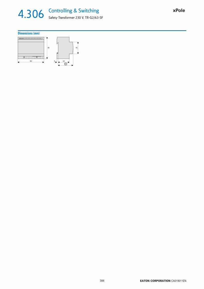
4.306
306 EATON CORPORATION CA019011EN
Controlling & Switching
Safety-Transformer 230 V, TR-G2/63-SF
Dimensions (mm)
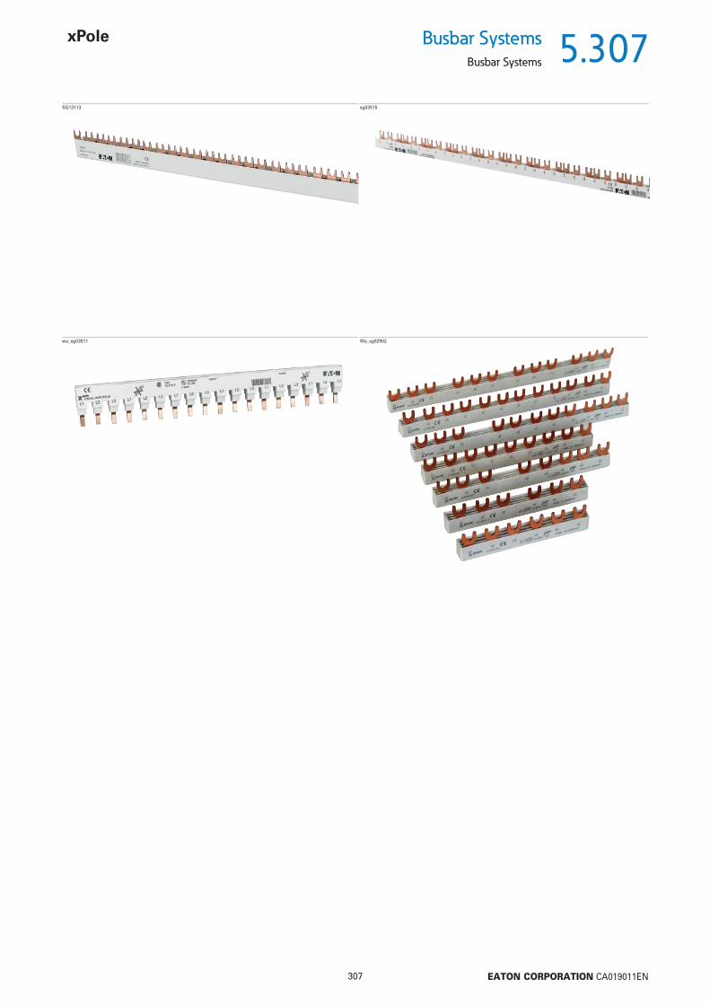
5.307
307 EATON CORPORATION CA019011EN
Busbar SystemsBusbar Systems
SG13113 sg03515
wa_sg03511 Wa_sg02902

5.308
308 EATON CORPORATION CA019011EN
Busbar Systems
Plug-in busbar System 50 A, 80 A ZV
Plug-in busbar System 50 A, 80 A ZV
wa_sg02618
End caps ZV-AEKBusbar cover ZV-ADPBusbarZV-SSZV-SS-80A
for PLS., CLS., PKN., PFIM, PFHM (with Auxiliary Switch)
Description Cu-factor TypeDesignation
Article No. Units perpackage
Connection Angle L1, NWA_SG08102
10 units 0.005 ZV-L1/N-10 263941 10 / 60036 units 0.005 ZV-L1/N-36 263942 36 / 2160100 units 0.005 ZV-L1/N-100 263943 100 / 3000
50 A
L1L1
NN
Same connection angle ZV-L1/N (-80A), for L1 and N, turned by 180°
10 units 0.005 ZV-L1/N-80A-10 263950 10 / 60036 units 0.005 ZV-L1/N-80A-36 263951 36 / 2160100 units 0.005 ZV-L1/N-80A-100 263952 100 / 3000
80 A
Connection Angle L2, L3WA_SG07902
10 units 0.007 ZV-L2/L3-10 263944 10 / 60036 units 0.007 ZV-L2/L3-36 263945 36 / 2160100 units 0.007 ZV-L2/L3-100 263946 100 / 3000
50 A
Same connection angle ZV-L2/L3(-80A), for L2 and L3, turned by 180°
10 units 0.007 ZV-L2/L3-80A-10 263953 10 / 60036 units 0.007 ZV-L2/L3-80A-36 263954 36 / 2160100 units 0.007 ZV-L2/L3-80A-100 263955 100 / 3000
80 AL2L2
L3L3
Connection Angle N (0.5 MU) for PLSM, CLS6 with 1.5 MUWA_SG08002
10 units 0.005 ZV-N-05TE-10 263947 10 / 60036 units 0.005 ZV-N-05TE-36 263948 36 / 2160
50 A
Same connection angle ZV-N-05TE for N (CLS6 with 1.5TE) 50 and 80 A busbar
100 units 0.005 ZV-N-05TE-100 263949 100 / 3000
80 A
NN
Busbar 1m330607, SG7997
0.143 ZV-SS 263956 1 / 10
50 A
0.230 ZV-SS-80A 263957 1 / 10
80 A
50 A, ZV-SS 80 A, ZV-SS-80A

5.309
309 EATON CORPORATION CA019011EN
Busbar SystemsPlug-in busbar System 50 A, 80 A ZV
Accessories Busbar cover 1m, for 50+80 A ZV-ADP 263958 1 / 10
End caps for busbar cover ZV-AEK 263959 10 / 600Power feed block 35/50mm2 Z-D80 248269 12 / 120
Description TypeDesignation
Article No. Units perpackage

5.310
310 EATON CORPORATION CA019011EN
Busbar Systems
Plug-in busbar System 50 A, 80 A ZV
Description Plug-in busbar System 50 A, 80 A ZV
• Any combinations of switchgear with or without auxiliary switch possible• Low number of components, 2 angle types per busbar cross-section for three-phases AC• Same busbar cover and end caps for ZV-SS and ZV-SS-80A• Short-circuit withstand strength and dielectric properties tested according to IEC/EN 60439-1
Technical Data
ZVElectricalRated operational voltage 240/415 VA CRated frequency 50/60 Hz, DCRated voltage 690 V (at Pollution degree 2)
440 V (at Pollution degree 3)Overvoltage category IIIRated peak withstand voltage Uimp 4 kVRated current
ZV-./., ZV-SS 50 AZV-./.-80A, ZV-SS-80A 80 AZV..-N-05TE 32 A
Conditional rated short circuit currentAC with 125 A gGZV-./., ZV-SS 50 kAZV-./.-80A, ZV-SS-80A 50 kAZV..-N-05TE 10 kAAC with 160 A gGZV-./., ZV-SS –ZV-./.-80A, ZV-SS-80A 50 kAZV..-N-05TE 10 kADC with 160 A gGZV-./., ZV-SS 10 kAZV-./.-80A, ZV-SS-80A 10 kAZV..-N-05TE –
MechanicalBusbar cross section
ZV-SS 16 mm2 CuZV-SS-80A 25 mm2 Cu
Busbar length 1 mDegree of protection mounted with busbar cover and end caps IP20Pollution degree 2 (3)Air gap 3.2 mmMinimum creepage distance 7 mm
Connection diagram
Dimensions (mm) 50 A Dimensions (mm) 80 A

5.311
311 EATON CORPORATION CA019011EN
Busbar SystemsBusbar Block (Fork) Z-GV
Busbar Block (Fork) Z-GV
Description Cu-factor TypeDesignation
Article No. Units perpackage
sg03515
1-phase 16x 0.095 Z-GV-16/1P-1MU/16 271074 502-phases 8x 0.187 Z-GV-16/1P+N-2MU/16 271075 204-phases 4x 0.444 Z-GV-16/3P+N-4MU/16 271078 15
16 mm2 - Rated current 80 A
• for PXL, PXK, PXF, PLS., CLS., PKN., PFIM, PFHM, Z-SLS/D01
Busbar Block (Fork) Z-GV• delivered with end caps
sg03515
1-phase 0.408 Z-GV-10/1P-1MU 270339 503-phases 0.739 Z-GV-10/3P-3MU 271060 203-phases 0.739 Z-GV-10/3P-4MU 271080 20End cap 1-phase Z-V-AK/1P 104905 10 / 600End cap 2+3-phases BB-EC/2+3P 120805 10 / 600
10 mm2 - Rated current 63 A
Busbar Block (Fork) Z-GV, 1 Meter• delivered without end caps
1-phase 0.470 Z-GV-16/1P-1MU 271061 501-phase + Auxiliary Switch 0.470 Z-GV-16/1P+HS 271062 502-phases 0.657 Z-GV-16/1P+N-2MU 271063 203-phases 1.042 Z-GV-16/3P-3MU 271064 203-phases + Auxiliary Switch 0.998 Z-GV-16/3P+HS 271065 204-phases 1.465 Z-GV-16/3P+N-4MU 271066 154-phases 1.522 Z-GV-16/3P+3N-6MU 263142 154-phases 1.050 Z-GV-16/PKPX/4PHAS 116882 10End cap 1-phase Z-V-AK/1P 104905 10 / 600End cap 2+3-phases BB-EC/2+3P 120805 10 / 600End cap 4-phases Z-V-AK/4P 264931 10 / 600
16 mm2 - Rated current 80 A
Accessories
Busbar Tag Shrouds for busbar, yellow ZV-BS-GSG05705 Finger and hand touch safe ZV-BS-G 104903 10/600
Description TypeDesignation
Article No. Units perpackage

5.312
312 EATON CORPORATION CA019011EN
Busbar Systems
Busbar Block (Fork) Z-GV
Devices to busbar Pcs. of the devices End caps Type
Description of the Busbar Block (Fork) Z-GV
1-phase
2-phases
3-phases
4-phases
For 2-pole Combined RCD/MCB Device, 3-phases
1-phase + Auxiliary Switch
3-phases + Auxiliary Switch
For 2-pole Combined RCD/MCB Device, 4-phases
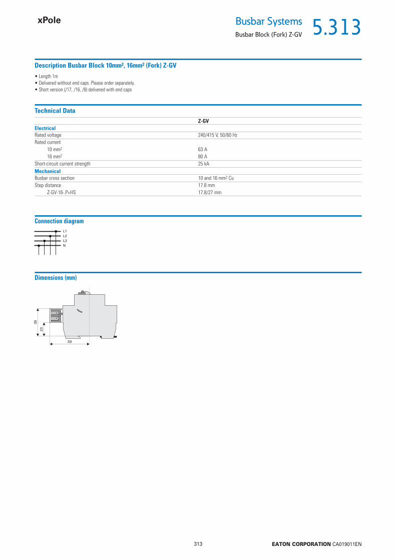
5.313
313 EATON CORPORATION CA019011EN
Busbar SystemsBusbar Block (Fork) Z-GV
Description Busbar Block 10mm2, 16mm2 (Fork) Z-GV
• Length 1m• Delivered without end caps. Please order separately.• Short version (/17, /16, /8) delivered with end caps
Technical DataZ-GV
ElectricalRated voltage 240/415 V, 50/60 HzRated current
10 mm2 63 A16 mm2 80 A
Short-circuit current strength 25 kAMechanicalBusbar cross section 10 and 16 mm2 CuStep distance 17.8 mm
Z-GV-16-.P+HS 17.8/27 mm
Connection diagram
Dimensions (mm)

5.314
314 EATON CORPORATION CA019011EN
Busbar Systems
Busbar Block (Fork and Pin) Z-GSV
Busbar Block (Fork and Pin) Z-GSV
Description Cu-factor TypeDesignation
Article No. Units perpackage
wa_sg01611
4-phases 0.208 Z-GSV-10/FI+EH+2XLS1N 113138 104-phases 0.277 Z-GSV-10/FI+EH+4XLS1N 113139 10
10 mm2 - Rated current 63 A
• for PLS.1N (1.5MU)
Busbar Block (Fork and Pin) Z-GSV• delivered with end caps
wa_sg01611
2-phases 0.585 Z-GSV-16/1P+N 271067 104-phases 1.840 Z-GSV-16/3P+3N 271068 104-phases 2.196 Z-GSV-16/FI+EH+KR+30XLS1N 113137 7End cap 4-phases Z-V-AK/4P 264931 10 / 600
16 mm2 - Rated current 80 A
Busbar Block (Fork and Pin) Z-GSV, 1 Meter• delivered without end caps
2-phases 9x 0.179 Z-GSV-16/1P+N/9 271077 154-phases 3x 0.408 Z-GSV-16/3P+3N/9 271079 15
16 mm2 - Rated current 80 A
Description of the Busbar Block (Fork and Pin) Z-GSV
Devices to busbar Pcs. of the devices End caps Type
2-phases
4-phases
4-phases
4-phases
4-phases
PHASE OUT
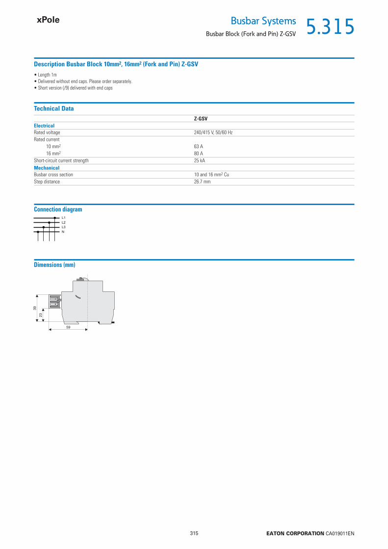
5.315
315 EATON CORPORATION CA019011EN
Busbar SystemsBusbar Block (Fork and Pin) Z-GSV
Description Busbar Block 10mm2, 16mm2 (Fork and Pin) Z-GSV
• Length 1m• Delivered without end caps. Please order separately.• Short version (/9) delivered with end caps
Technical DataZ-GSV
ElectricalRated voltage 240/415 V, 50/60 HzRated current
10 mm2 63 A16 mm2 80 A
Short-circuit current strength 25 kAMechanicalBusbar cross section 10 and 16 mm2 CuStep distance 26.7 mm
Connection diagram
Dimensions (mm)

5.316
316 EATON CORPORATION CA019011EN
Busbar Systems
Busbar Block (Pin) Z-SV...-SD, 1 Meter
Busbar Block (Pin) Z-SV...-SD, 1 Meter
Description Cu-factor TypeDesignation
Article No. Units perpackage
• For Protected Earth Socket Z-SD230• delivered with end caps
2-phases 0.588 Z-SV-10/1P+N-SD 269526 10End caps Z-V-AK/2+3P 264930 10 / 600
10 mm2 - Rated current 50 A
Description Busbar Block 10mm2 (Pin) Z-SV ...-SD
• Delivered without end caps• Step (distance between two pins of identical phase, i. e. L or N) 2.5 MU• Length 1 m
Technical DataZ-SV-10/1P+N-SD
ElectricalRated voltage 230/400 V, 50/60 HzRated current 50 AShort-circuit current strength 25 kAMechanicalBusbar cross section 10 mm2 CuStep distance 44 mm
Connection diagram
AccessoriesWA_SG10602
End caps
WA_SG10702
Extension terminal Z-EK/25/QL
WA_SG10702
Extension terminal Z-EK/25

5.317
317 EATON CORPORATION CA019011EN
Busbar SystemsBusbar Block (Pin) Z-SV
Busbar Block (Pin) Z-SV
Description Cu-factor TypeDesignation
Article No. Units perpackage
WA_SG11302
1-phase straight grey 0.055 Z-SV-10/1P-1MU/13 264916 101-phase straight blue 0.055 Z-SV-10/N-1MU/13 264917 101-phase angulated grey 0.055 Z-SV-10/1P-F/13 264918 101-phase angulated blue 0.055 Z-SV-10/N-F/13 264919 102-phases 0.126 Z-SV-10/2P-2MU/13 264922 103-phases 0.203 Z-SV-10/3P-3TE/13 264924 104-phases 0.258 Z-SV-10/3P+N-4TE/12 264926 104-phases (for PLN.) 0.258 Z-SV-10/3P+3N-3TE/13 264927 10
10 mm2 - Rated current 50 A
• for PLN. (1MU), Z-SI
Busbar Block (Pin) Z-SV, 13TE• delivered with end caps
WA_SG11302
1-phase straight grey 0.385 Z-SV-16/1P-1MU 264912 251-phase straight blue 0.385 Z-SV-16/N-1MU 264913 251-phase angulated grey 0.385 Z-SV-16/1P-1MU/F 269523 251-phase angulated blue 0.385 Z-SV-16/N-1MU/F 269524 252-phases 0.941 Z-SV-16/2P-2MU 264923 103-phases (for PLN.) 1.326 Z-SV-16/2P+2N-2MU 264914 73-phases 1.422 Z-SV-16/3P-3TE 264925 104-phases 2.177 Z-SV-16/3P+N-4TE 264928 74-phases (for PLN.) 1.807 Z-SV-16/3P+3N-3TE 264915 7
16 mm2 - Rated current 63 A
Busbar Block (Pin) Z-SV, 1 Meter• delivered without end caps
Accessories
Busbar Tag Shrouds for busbar, yellow ZV-BS-GSG05705 Finger and hand touch safe ZV-BS-G 104903 10/600
Description TypeDesignation
Article No. Units perpackage
End caps, Z-V-AK/, Z-BB-EC/4Pwa_sg05413 1-phase Z-V-AK/1P 104905 10 / 600
2+3-phases Z-V-AK/2+3P 264930 10 / 6004-phases Z-BB-EC/4P 1) 183116 10 / 6001) only for Z-SV-16/3P+N-4TE, Article No. 264928
Extension terminals 6 - 25 mm2, Z-EK/25wa_sg02512 long, straight Z-EK/25 264935 10 / 600
short, straight Z-EK/25/K 269525 10 / 600long, crosswise Z-EK/25/QL 264937 10 / 600short, crosswise Z-EK/25/Q 264936 10 / 600

5.318
318 EATON CORPORATION CA019011EN
Busbar Systems
Busbar Block (Pin) Z-SV
Devices to busbar Pcs. of the devices End caps Type
Description of the Busbar Block (Pin) Z-SV
Example
L3L1
Z-SV-10/1P-F/13, Z-SV-16/1P-1TE/FZ-SV-10/N-F/13, Z-SV-16/N-1TE/F
58
98
L N
62
102
L N
Z-SV-.. 2-phasig bis 4-phasig
73
113
L2 N
76
116
L1 L2 L3 N
Extension terminal Z-EK/25/QL
Extension terminal Z-EK/25
Extension terminal Z-EK/25/Q
Extension terminal Z-EK/25/K
1-phase + 2-phases
2-phases
3-phases
4-phases
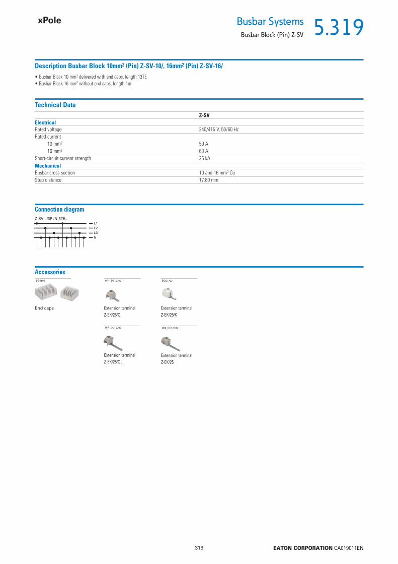
5.319
319 EATON CORPORATION CA019011EN
Busbar SystemsBusbar Block (Pin) Z-SV
Description Busbar Block 10mm2 (Pin) Z-SV-10/, 16mm2 (Pin) Z-SV-16/
• Busbar Block 10 mm2 delivered with end caps, length 13TE• Busbar Block 16 mm2 without end caps, length 1m
Technical DataZ-SV
ElectricalRated voltage 240/415 V, 50/60 HzRated current
10 mm2 50 A16 mm2 63 A
Short-circuit current strength 25 kAMechanicalBusbar cross section 10 and 16 mm2 CuStep distance 17.80 mm
Connection diagramZ-SV-../3P+N-3TE..
AccessoriesSG4800
End caps
WA_SG10702
Extension terminal Z-EK/25/QL
WA_SG10702
Extension terminal Z-EK/25
WA_SG10702
Extension terminal Z-EK/25/Q
SG07703
Extension terminal Z-EK/25/K
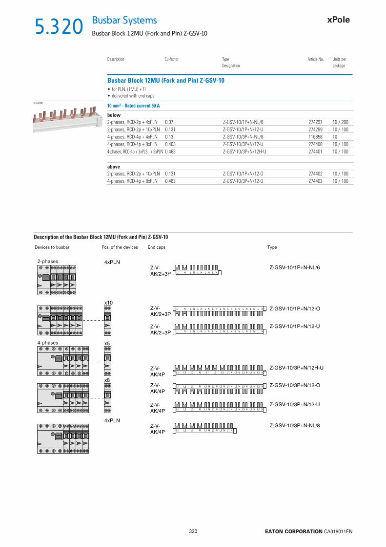
5.320
320 EATON CORPORATION CA019011EN
Busbar Systems
Busbar Block 12MU (Fork and Pin) Z-GSV-10
Busbar Block 12MU (Fork and Pin) Z-GSV-10
Description Cu-factor TypeDesignation
Article No. Units perpackage
SG4700
below2-phases, RCD-2p + 4xPLN 0.07 Z-GSV-10/1P+N-NL/6 274297 10 / 2002-phases, RCD-2p + 10xPLN 0.131 Z-GSV-10/1P+N/12-U 274299 10 / 1004-phases, RCD-4p + 4xPLN 0.13 Z-GSV-10/3P+N-NL/8 116858 104-phases, RCD-4p + 8xPLN 0.463 Z-GSV-10/3P+N/12-U 274400 10 / 1004-phases, RCD-4p + 3xPLS.. + 5xPLN 0.463 Z-GSV-10/3P+N/12H-U 274401 10 / 100
above2-phases, RCD-2p + 10xPLN 0.131 Z-GSV-10/1P+N/12-O 274402 10 / 1004-phases, RCD-4p + 8xPLN 0.463 Z-GSV-10/3P+N/12-O 274403 10 / 100
10 mm2 - Rated current 50 A
• for PLN. (1MU) + FI• delivered with end caps
Description of the Busbar Block 12MU (Fork and Pin) Z-GSV-10
Devices to busbar Pcs. of the devices End caps Type
2-phases
4-phases
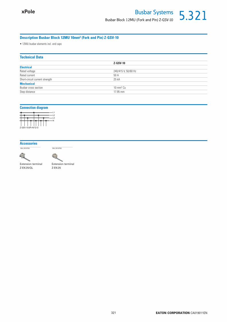
5.321
321 EATON CORPORATION CA019011EN
Busbar SystemsBusbar Block 12MU (Fork and Pin) Z-GSV-10
Description Busbar Block 12MU 10mm2 (Fork and Pin) Z-GSV-10
• 12MU busbar elements incl. end caps
Technical DataZ-GSV-10
ElectricalRated voltage 240/415 V, 50/60 HzRated current 50 AShort-circuit current strength 25 kAMechanicalBusbar cross section 10 mm2 CuStep distance 17.95 mm
Connection diagram
Z-GSV-10/3P+N/12-O
AccessoriesWA_SG10702
Extension terminal Z-EK/25/QL
WA_SG10702
Extension terminal Z-EK/25

5.322
322 EATON CORPORATION CA019011EN
Busbar Systems
Busbar Block 13MU (Fork and Pin) Z-GSV-10
Busbar Block 13MU (Fork and Pin) Z-GSV-10
Description Cu-factor TypeDesignation
Article No. Units perpackage
wa_sg14303
above2-phases, RCD-2p + 11xPLG 0.251 Z-GSV-10/1P+N-F/13 264920 10
10 mm2 - Rated current 63 A
• for 1x RCD + PLG. (1MU)
• Do not cut!!
Accessories
Busbar Tag Shrouds for busbar, yellow ZV-BS-GSG05705 Finger and hand touch safe ZV-BS-G 104903 10/600
Description TypeDesignation
Article No. Units perpackage
Extension terminals 6 - 25 mm2, Z-EK/25wa_sg02512 long, straight Z-EK/25 264935 10 / 600
long, crosswise Z-EK/25/QL 264937 10 / 600
Description of the Busbar Block 13MU (Fork and Pin) Z-GSV-10
N NL L N L N L N L N L N L N L N L N L N L N L Z-GSV-10/1P+N-F/13
2-phasig x11
Devices to busbar Pcs. of the devices Type
Description Busbar Block 13MU 10mm2 (Fork and Pin) Z-GSV-10
• 13MU busbar elements without end caps
Technical DataZ-GSV-10
ElectricalRated voltage 240/415 V, 50/60 HzRated current 63 AShort-circuit current strength 25 kAMechanicalBusbar cross section 10 mm2 CuStep distance 17.95 mm
Connection diagram
Z-GSV-10/3P+N-F/13
AccessoriesWA_SG10602
End caps
WA_SG10702
Extension terminal Z-EK/25/QL
WA_SG10702
Extension terminal Z-EK/25
2-phases

5.323
323 EATON CORPORATION CA019011EN
Busbar SystemsBusbar Block (Pin) Z-SV-../1P+N-F
Busbar Block (Pin) Z-SV-../1P+N-F
Description Cu-factor TypeDesignation
Article No. Units perpackage
SG07106
PFGC + 4x PLGC 0.105 Z-SV-10/1P+N-F/6 107944 10 / 100PFGC + 7x PLGC 0.155 Z-SV-10/1P+N-F/9 107943 10 / 100PFGC + 11x PLGC 0.22 Z-SV-10/1P+N-F/13 107942 10 / 100
10 mm2 - Rated current 50 A
• for 1x PFGC + PLGC. (1MU)• 2-phases
• Do not cut!!
PFGC + 4x PLGC 0.155 Z-SV-16/1P+N-F/6 191245 10 / 100PFGC + 7x PLGC 0.231 Z-SV-16/1P+N-F/9 191244 10 / 100PFGC + 8x PLGC 0.259 Z-SV-16/1P+N-F/10 191246 10 / 100PFGC + 11x PLGC 0.328 Z-SV-16/1P+N-F/13 191243 10 / 100
16 mm2 - Rated current 63 A
Accessories
Busbar Tag Shrouds for busbar, yellow ZV-BS-GSG05705 Finger and hand touch safe ZV-BS-G 104903 10/600
Description TypeDesignation
Article No. Units perpackage
Description of the Busbar Block (Pin) Z-SV-../1P+N-F
Devices to busbar Pcs. of the devices Type
Description Busbar Block 10/16mm2 (Pin) Z-SV-../1P+N-F
• Busbar elements without end caps
2-phases

5.324
324 EATON CORPORATION CA019011EN
Busbar Systems
Busbar Block (Pin) Z-SV-../1P+N-F
Technical DataZ-SV-../1P+N-F
ElectricalRated voltage 240/415 V, 50/60 HzRated current
10 mm2 50 A16 mm2 63 A
Overvoltage category IIIRated peak withstand voltage Uimp 4 kVConditional rated short circuit current AC with 125 A gG 10 kAMechanicalBusbar cross section 10 and 16 mm2 CuStep distance 17.8 mmFlame class according to UL94 V0, glowing wire test 960 °CPollution degree 2Comparative tracking index CTI 300Air gap 5.5 mmMinimum creepage distance 5 mm
Dimensions (mm)
Z-SV-10/1P+N-F/6, Z-SV-16/1P+N-F/6
Z-SV-10/1P+N-F/9, Z-SV-16/1P+N-F/9
Z-SV-16/1P+N-F/10
Z-SV-10/1P+N-F/13, Z-SV-16/1P+N-F/13
Connection diagram

5.325
325 EATON CORPORATION CA019011EN
Busbar SystemsBusbar Block (Pin) Z-SV
Busbar Block (Pin) Z-SV
Description Cu-factor TypeDesignation
Article No. Units perpackage
wa_sg03611
3-phases 0.84 Z-SV-16/3P 271072 20
16 mm2 - Rated current 80 A
• delivered without end caps
Busbar Block (Pin) Z-SV-16/3P• for Z-SLS, PLHT, D0.-SO/.. (1.5MU)
Accessories for Z-SV-16/3P
Extension terminalwa_sg05913 Extension terminal 6-50 mm2 Z-EK/50 264934 3 / 180
End capSG4800 End cap Z-V-35/AK/3P 264932 10 / 600
1-phase angulated grey 0.83 Z-SV-35/1P 113135 13-phases 2.74 Z-SV-35/3P 264938 43-phases 2.74 Z-SV-35/PLHT-V 264939 44-phases* 1.57 Z-SV-35/3P+N-6TE 263110 4* delivered with end caps
35 mm2 - Rated current 110 A
Busbar Block (Pin) Z-SV-35• for Z-SLS, PLHT, D0.-SO/.. (1.5MU), PLHT-V (1.5MU)
Accessories for Z-SV-35
End capSG4800 End cap Z-V-35/AK/3P 264932 10 / 600
wa_sg03711
Accessories for Z-SV-35
Extension terminals Z-EK/95
wa_sg05513 for Z-SV-35/1P Z-EK/95-1 113136 3 / 90for Z-SV-... 3-phases Z-EK/95 264933 3 / 90for Z-SV-35/3P+N Z-EK/95-3N 264911 4 / 120
• 25-95 mm2 single-/multi-wire• 16-70 mm2 fi ne wires with wire end sleeve

5.326
326 EATON CORPORATION CA019011EN
Busbar Systems
Busbar Block (Pin) Z-SV
Description of the Busbar Block (Pin) Z-SV
Devices to busbar Pcs. of the devices End caps Type
Description Busbar Block (Pin) Z-SV
• End caps are to be ordered separately, exception Z-SV-35/3P+N-6TE• Halogenfree plastic
Technical DataZ-SV-16 Z-SV-35
ElectricalRated operational voltage 240/415 V AC 240/415 V ACRated frequency 50/60 Hz 50/60 HzRated voltage 500 V 690 VOvervoltage category III IIIRated peak withstand voltage Uimp 4 kV 6 kVRated current 80 A 110 AConditional rated short circuit current AC with 250 A gG 50 kAr.m.s. 100 kAr.m.s.
MechanicalBusbar cross section 16 mm2 Cu 35 mm2 CuStep distance 27 mm 27 mm (Z-SV-35/PLHT-V 30.5 mm)Flame class according to UL94 V0, glowing wire test 960 °C V0, glowing wire test 850 °CDegree of protection, with end caps IP20 IP20Pollution degree 2 2Comparative tracking index CTI 300 CTI 600Air gap 5 mm 4.3 mmMinimum creepage distance 10.2 mm 6.7 mm
3-phases
4-phases
1-phase

5.327
327 EATON CORPORATION CA019011EN
Busbar SystemsBusbar Block (Pin) Z-SV
Dimensions (mm)
Z-SV-35/3P+N-6TE
Z-SV-35/1P
Extension terminal Z-EK/50
Accessories for Z-SV-35
Wa_sg10802
Extension terminalnZ-EK/95, Z-EK/95-3N, Z-EK/95-1
Wa_sg10802
Accessories for Z-SV-16
n A B C D E F G H IZ-SV-16/3P 35 27 5 945 971 14.9 31 1.5 17 19Z-SV-35/3P 35 27 8.5 945 1000 19.7 38.4 2.5 21.5 23.9Z-SV-35/PLHT-V 32 30.5 8.5 976 1000 19.7 38.4 2.5 21.5 23.9
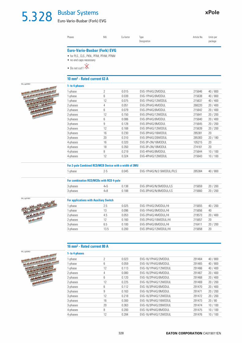
5.328
328 EATON CORPORATION CA019011EN
Busbar Systems
Euro-Vario-Busbar (Fork) EVG
Euro-Vario-Busbar (Fork) EVG
Phases MU Cu-factor TypeDesignation
Article No. Units perpackage
Wa_sg02902
1-phase 2 0.015 EVG-1PHAS/2MODUL 215646 40 / 8001-phase 6 0.039 EVG-1PHAS/6MODUL 215638 40 / 8001-phase 12 0.075 EVG-1PHAS/12MODUL 215637 40 / 4002-phases 4 0.051 EVG-2PHAS/4MODUL 268220 20 / 4002-phases 6 0.079 EVG-2PHAS/6MODUL 215642 20 / 4002-phases 12 0.150 EVG-2PHAS/12MODUL 215641 20 / 2003-phases 6 0.086 EVG-3PHAS/6MODUL 215640 20 / 4003-phases 9 0.128 EVG-3PHAS/9MODUL 215645 20 / 2003-phases 12 0.168 EVG-3PHAS/12MODUL 215639 20 / 2003-phases 16 0.230 EVG-3PHAS/16MODUL 285381 203-phases 20 0.310 EVG-3PHAS/20MODUL 285383 20 / 1804-phases 16 0.320 EVG-3P+3N/16MODUL 105215 204-phases 18 0.350 EVG-3P+3N/18MODUL 274161 204-phases 8 0.219 EVG-4PHAS/8MODUL 215644 10 / 1004-phases 12 0.324 EVG-4PHAS/12MODUL 215643 10 / 100
1- to 4-phases
• for PLS., CLS., PKN., PFIM, PFHM, PFNM• no end caps necessary
• Do not cut!!
10 mm2 - Rated current 63 A
1-phase 2-5 0.045 EVG-1PHAS/N/2-5MODUL/FILS 285384 40 / 800
For 2-pole Combined RCD/MCB Device with a width of 3MU
3-phases 4+5 0.138 EVG-3PHAS/N/5MODUL/LS 215659 20 / 2003-phases 4+8 0.188 EVG-3PHAS/N/8MODUL/LS 215660 20 / 200
For combination RCD/MCBs with RCD 4-pole
Wa_sg01602
1-phase 2.5 0.025 EVG-1PHAS/2MODUL/HI 215655 40 / 2001-phase 13 0.096 EVG-1PHAS/9MODUL/HI 215656 402-phases 4.5 0.053 EVG-2PHAS/4MODUL/HI 219573 20 / 4002-phases 12 0.160 EVG-2PHAS/10MODUL/HI 215657 203-phases 6.5 0.100 EVG-3PHAS/6MODUL/HI 216411 20 / 2003-phases 13.5 0.200 EVG-3PHAS/12MODUL/HI 215658 20
For applications with Auxiliary Switch
Wa_sg02902
1-phase 2 0.023 EVG-16/1PHAS/2MODUL 291464 40 / 8001-phase 6 0.059 EVG-16/1PHAS/6MODUL 291465 40 / 8001-phase 12 0.113 EVG-16/1PHAS/12MODUL 291466 40 / 4002-phases 4 0.080 EVG-16/2PHAS/4MODUL 291467 20 / 4002-phases 6 0.120 EVG-16/2PHAS/6MODUL 291468 20 / 4002-phases 12 0.225 EVG-16/2PHAS/12MODUL 291469 20 / 2003-phases 6 0.112 EVG-16/3PHAS/6MODUL 291470 20 / 4003-phases 9 0.163 EVG-16/3PHAS/9MODUL 291471 20 / 2003-phases 12 0.218 EVG-16/3PHAS/12MODUL 291472 20 / 2003-phases 16 0.300 EVG-16/3PHAS/16MODUL 291473 20 / 803-phases 20 0.363 EVG-16/3PHAS/20MODUL 291474 10 / 1004-phases 8 0.200 EVG-16/4PHAS/8MODUL 291475 10 / 1004-phases 12 0.284 EVG-16/4PHAS/12MODUL 291476 10 / 100
1- to 4-phases
16 mm2 - Rated current 80 A
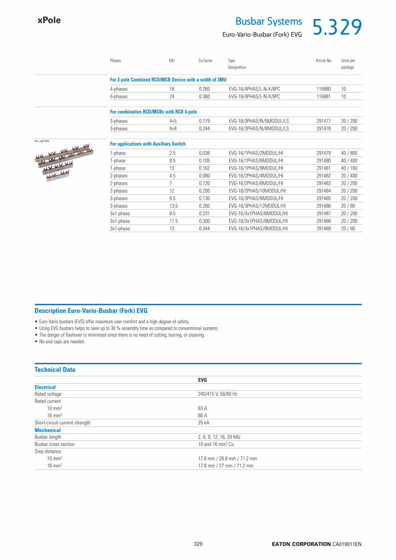
5.329
329 EATON CORPORATION CA019011EN
Busbar SystemsEuro-Vario-Busbar (Fork) EVG
Phases MU Cu-factor TypeDesignation
Article No. Units perpackage
4-phases 18 0.260 EVG-16/4PHAS/L-N-X/6PC 116880 104-phases 24 0.360 EVG-16/4PHAS/L-N-X/8PC 116881 10
For 2-pole Combined RCD/MCB Device with a width of 3MU
3-phases 4+5 0.179 EVG-16/3PHAS/N/5MODUL/LS 291477 20 / 2003-phases 4+8 0.244 EVG-16/3PHAS/N/8MODUL/LS 291478 20 / 200
For combination RCD/MCBs with RCD 4-pole
Wa_sg01602
1-phase 2.5 0.038 EVG-16/1PHAS/2MODUL/HI 291479 40 / 8001-phase 8.5 0.105 EVG-16/1PHAS/6MODUL/HI 291480 40 / 4001-phase 13 0.162 EVG-16/1PHAS/9MODUL/HI 291481 40 / 1602-phases 4.5 0.080 EVG-16/2PHAS/4MODUL/HI 291482 20 / 4002-phases 7 0.120 EVG-16/2PHAS/6MODUL/HI 291483 20 / 2002-phases 12 0.200 EVG-16/2PHAS/10MODUL/HI 291484 20 / 2003-phases 6.5 0.130 EVG-16/3PHAS/6MODUL/HI 291485 20 / 2003-phases 13.5 0.260 EVG-16/3PHAS/12MODUL/HI 291486 20 / 803x1-phase 8.5 0.231 EVG-16/3x1PHAS/6MODUL/HI 291487 20 / 2003x1-phase 11.5 0.300 EVG-16/3x1PHAS/8MODUL/HI 291488 20 / 2003x1-phase 13 0.344 EVG-16/3x1PHAS/9MODUL/HI 291489 20 / 80
For applications with Auxiliary Switch
Description Euro-Vario-Busbar (Fork) EVG
• Euro Vario busbars (EVG) offer maximum user comfort and a high degree of safety.• Using EVG busbars helps to save up to 30 % assembly time as compared to conventional systems.• The danger of fl ashover is minimised since there is no need of cutting, burring, or cleaning.• No end caps are needed.
Technical DataEVG
ElectricalRated voltage 240/415 V, 50/60 HzRated current
10 mm2 63 A16 mm2 80 A
Short-circuit current strength 25 kAMechanicalBusbar length 2, 6, 9, 12, 16, 20 MUBusbar cross section 10 and 16 mm2 CuStep distance
10 mm2 17.8 mm / 26.8 mm / 71.2 mm16 mm2 17.8 mm / 27 mm / 71.2 mm

5.330
330 EATON CORPORATION CA019011EN
Busbar Systems
Euro-Vario-Busbar (Fork) EVG
Description of Euro-Vario-Busbar (Fork) EVG
Devices to busbar Pcs. of the devices Type
1-phase
2-phases
3-phases
4-phases
For 2-pole Combined RCD/MCB Device, 1-phase
For combination RCD/MCBs with RCD 4-pole, 3-phases
1-phase + Auxiliary Switch
2-phases + Auxiliary Switch
3-phases + Auxiliary Switch
For 2-pole Combined RCD/MCB Device, 4-phases
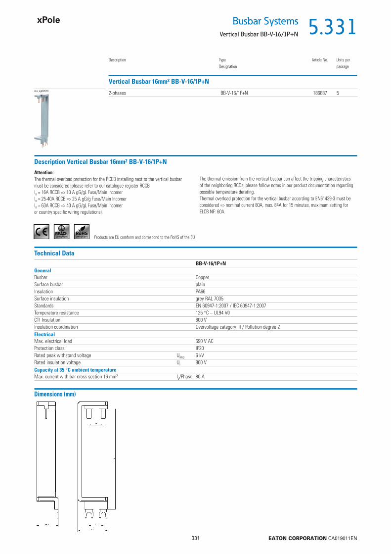
5.331
331 EATON CORPORATION CA019011EN
Busbar SystemsVertical Busbar BB-V-16/1P+N
Description TypeDesignation
Article No. Units perpackage
Vertical Busbar 16mm2 BB-V-16/1P+Nwa_sg02616 2-phases BB-V-16/1P+N 186887 5
Description Vertical Busbar 16mm2 BB-V-16/1P+N
Attention:The thermal overload protection for the RCCB installing next to the vertical busbar must be considered (please refer to our catalogue register RCCBIn = 16A RCCB => 10 A gG/gL Fuse/Main IncomerIn = 25-40A RCCB => 25 A gG/g Fuse/Main IncomerIn = 63A RCCB => 40 A gG/gL Fuse/Main Incomeror country specifi c wiring regulations).
The thermal emission from the vertical busbar can affect the tripping characteristics of the neighboring RCDs, please follow notes in our product documentation regarding possible temperature derating.Thermal overload protection for the vertical busbar according to EN61439-3 must be considered => nominal current 80A, max. 84A for 15 minutes, maximum setting for ELCB NF: 60A.
Technical DataBB-V-16/1P+N
GeneralBusbar CopperSurface busbar plainInsulation PA66Surface insulation grey RAL 7035Standards EN 60947-1:2007 / IEC 60947-1:2007Temperature resistance 125 °C – UL94 V0CTI Insulation 600 VInsulation coordination Overvoltage category III / Pollution degree 2ElectricalMax. electrical load 690 V ACProtection class IP20Rated peak withstand voltage Uimp 6 kVRated insulation voltage Ui 800 VCapacity at 35 °C ambient temperatureMax. current with bar cross section 16 mm2 Is/Phase 80 A
Products are EU comform and correspond to the RoHS of the EU
Dimensions (mm)
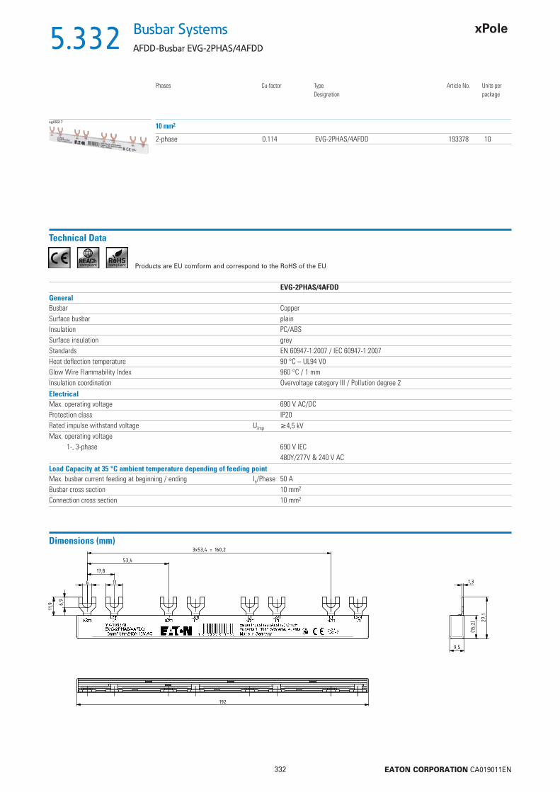
5.332
332 EATON CORPORATION CA019011EN
Busbar Systems
AFDD-Busbar EVG-2PHAS/4AFDD
sg05517
2-phase 0.114 EVG-2PHAS/4AFDD 193378 10
Phases Cu-factor Type Article No. Units perDesignation package
10 mm2
Technical Data
EVG-2PHAS/4AFDDGeneralBusbar CopperSurface busbar plainInsulation PC/ABSSurface insulation greyStandards EN 60947-1:2007 / IEC 60947-1:2007Heat defl ection temperature 90 °C – UL94 V0Glow Wire Flammability Index 960 °C / 1 mmInsulation coordination Overvoltage category III / Pollution degree 2ElectricalMax. operating voltage 690 V AC/DCProtection class IP20Rated impulse withstand voltage Uimp 4,5 kVMax. operating voltage
1-, 3-phase 690 V IEC480Y/277V & 240 V AC
Load Capacity at 35 °C ambient temperature depending of feeding pointMax. busbar current feeding at beginning / ending Is/Phase 50 ABusbar cross section 10 mm2
Connection cross section 10 mm2
Products are EU comform and correspond to the RoHS of the EU
Dimensions (mm)
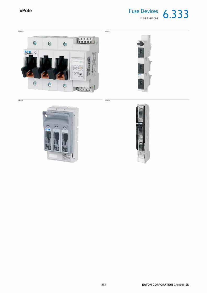
6.333
333 EATON CORPORATION CA019011EN
Fuse DevicesFuse Devices
SG80911 sg82311
vt61615 sg09610
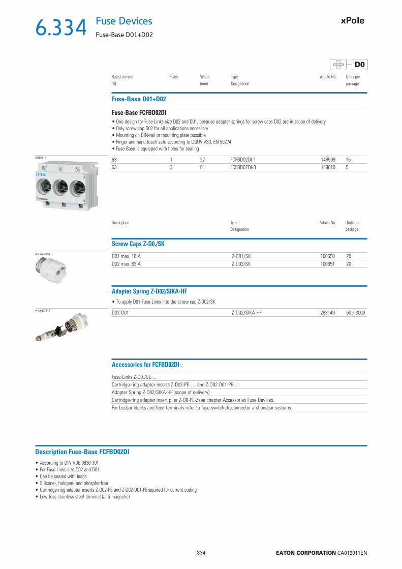
6.334
334 EATON CORPORATION CA019011EN
Fuse Devices
Fuse-Base D01+D02
D0
Fuse-Base D01+D02
Rated current(A)
Poles Width(mm)
TypeDesignation
Article No. Units perpackage
SG80211 63 1 27 FCFBD02DI-1 148599 1563 3 81 FCFBD02DI-3 148810 5
• One design for Fuse-Links size D02 and D01, because adapter springs for screw caps D02 are in scope of delivery• Only screw cap D02 for all applications necessary• Mounting on DIN-rail or mounting plate possible• Finger and hand touch safe according to DGUV VS3, EN 50274• Fuse-Base is equipped with holes for sealing
Description TypeDesignation
Article No. Units perpackage
Fuse-Base FCFBD02DI
Screw Caps Z-D0./SKwa_sg04013 D01 max. 16 A Z-D01/SK 100650 20
D02 max. 63 A Z-D02/SK 100651 20
Adapter Spring Z-D02/SIKA-HF
wa_sg02612 D02-D01 Z-D02/SIKA-HF 263149 50 / 3000
• To apply D01-Fuse-Links into the screw cap Z-D02/SK
Accessories for FCFBD02DI-.
Fuse-Links Z-D0./SE-...Cartridge-ring adapter inserts Z-D02-PE-… and Z-D02-D01-PE-…Adapter Spring Z-D02/SIKA-HF (scope of delivery)Cartridge-ring adapter insert plier Z-D0-PE-Zsee chapter Accessories Fuse Devices.For busbar blocks and feed terminals refer to fuse-switch-disconnector and busbar systems.
Description Fuse-Base FCFBD02DI
• According to DIN VDE 0636-301• For Fuse-Links size D02 and D01• Can be sealed with leads• Silicone-, halogen- and phosphorfree• Cartridge-ring adapter inserts Z-D02-PE and Z-D02-D01-PErequired for current coding• Low-loss stainless steel terminal (anti-magnetic)
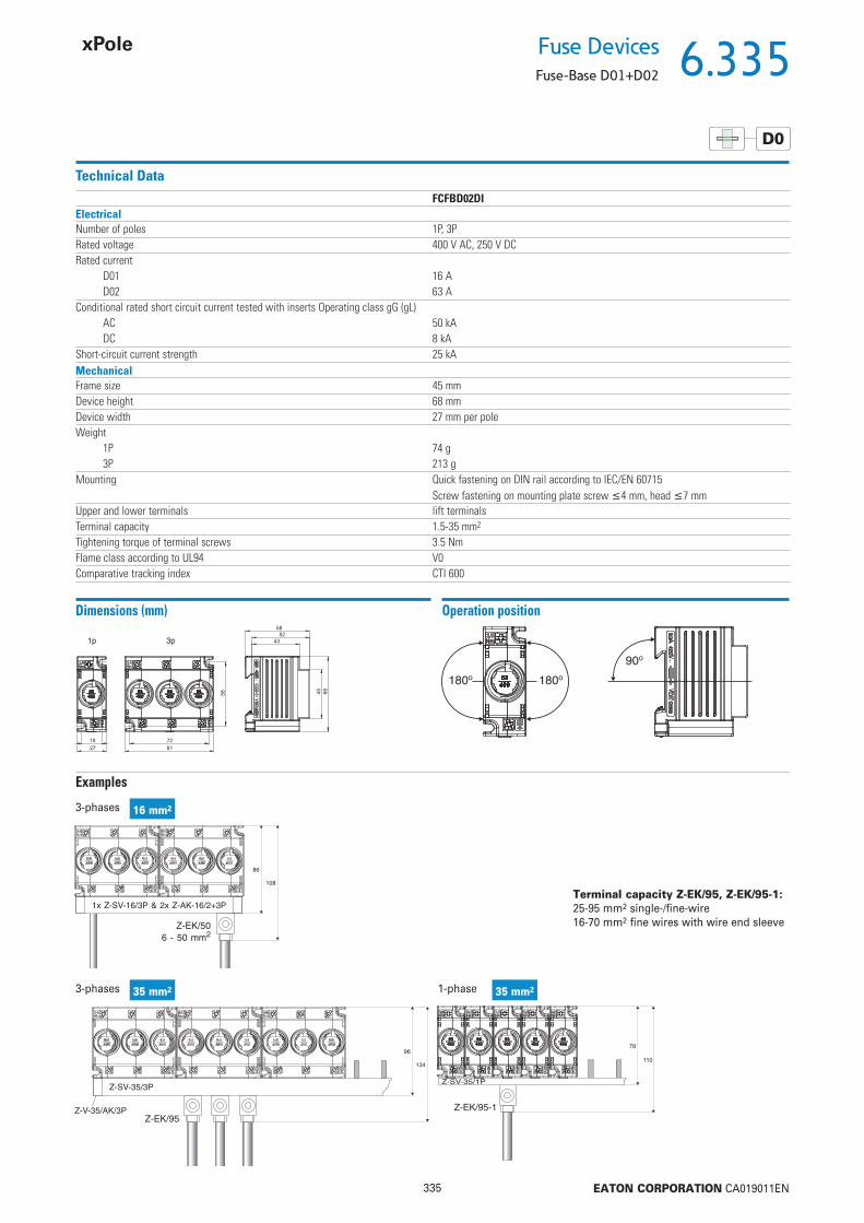
6.335
335 EATON CORPORATION CA019011EN
Fuse DevicesFuse-Base D01+D02
D0
Technical DataFCFBD02DI
ElectricalNumber of poles 1P, 3PRated voltage 400 V AC, 250 V DCRated current
D01 16 AD02 63 A
Conditional rated short circuit current tested with inserts Operating class gG (gL)AC 50 kADC 8 kA
Short-circuit current strength 25 kAMechanicalFrame size 45 mmDevice height 68 mmDevice width 27 mm per poleWeight
1P 74 g3P 213 g
Mounting Quick fastening on DIN rail according to IEC/EN 60715Screw fastening on mounting plate screw 4 mm, head 7 mm
Upper and lower terminals lift terminalsTerminal capacity 1.5-35 mm2
Tightening torque of terminal screws 3.5 NmFlame class according to UL94 V0Comparative tracking index CTI 600
Dimensions (mm) Operation position
Examples
3-phases 16 mm2
1-phase 35 mm23-phases 35 mm2
Terminal capacity Z-EK/95, Z-EK/95-1:25-95 mm2 single-/fi ne-wire16-70 mm2 fi ne wires with wire end sleeve
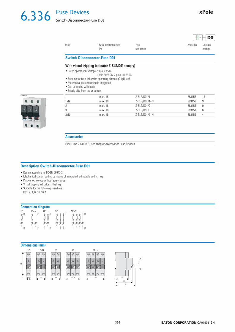
6.336
336 EATON CORPORATION CA019011EN
Fuse Devices
Switch-Disconnector-Fuse D01
D0
Switch-Disconnector-Fuse D01
Poles Rated constant current(A)
TypeDesignation
Article No. Units perpackage
SG80411 1 max. 16 Z-SLS/D01/1 263155 181+N max. 16 Z-SLS/D01/1+N 263158 92 max. 16 Z-SLS/D01/2 263156 93 max. 16 Z-SLS/D01/3 263157 63+N max. 16 Z-SLS/D01/3+N 263159 4
• Rated operational voltage 230/400 V AC1-pole 60 V DC, 2-pole 110 V DC
• Suitable for fuse-links with operating classes gG (gL), aM• Mechanical current coding is integrated• Can be sealed with leads• Supply side from top or bottom
With visual tripping indicator Z-SLS/D01 (empty)
Accessories
Fuse-Links Z-D01/SE-..see chapter Accessories Fuse Devices
Description Switch-Disconnector-Fuse D01
• Design according to IEC/EN 60947-3• Mechanical current coding by means of integrated, adjustable coding ring• Plug-in technology without screw caps• Visual tripping indicator is fl ashing• Suitable for the following fuse-links
D01: 2, 4, 6, 10, 16 A
Connection diagram1P 1P+N 2P 3P 3P+N
Dimensions (mm)

6.337
337 EATON CORPORATION CA019011EN
Fuse DevicesSwitch-Disconnector-Fuse D01
D0
Technical DataZ-SLS/D01
ElectricalNumber of poles 1P, 1P+N, 2P, 3P, 3P+NRated operational voltage Ue
AC 400 VDC 1P to 60 V / 2P to 110 V
Rated operational current Ie 16 ARated constant current Iu 16 AConditional rated short circuit current 50 kAr.m.s.
Utilization category AC 22B, DC 21BOvervoltage category IVRated peak withstand voltage Uimp 6 kVPower loss per current path Ie 0.64 WPower loss per current path with fuse-link Ie 2.24 WMechanicalFrame size 45 mmDevice height 86 mmDevice width 17.5 mm per pole (1MU)Weight
1P 90 g1P+N 170 g2P 180 g3P 270 g3P+N 350 g
Mounting Quick fastening on DIN rail according to IEC/EN 60715Degree of protection IP20Upper and lower terminals lift terminalsTerminal capacity 1.5-25 mm2
Tightening torque of terminal screws max. 2.5 NmTemperature range -25 to +60 °CFlame class V0, glowing wire test 960 °CPollution degree 3Comparative tracking index CTI 600
Examples
oder
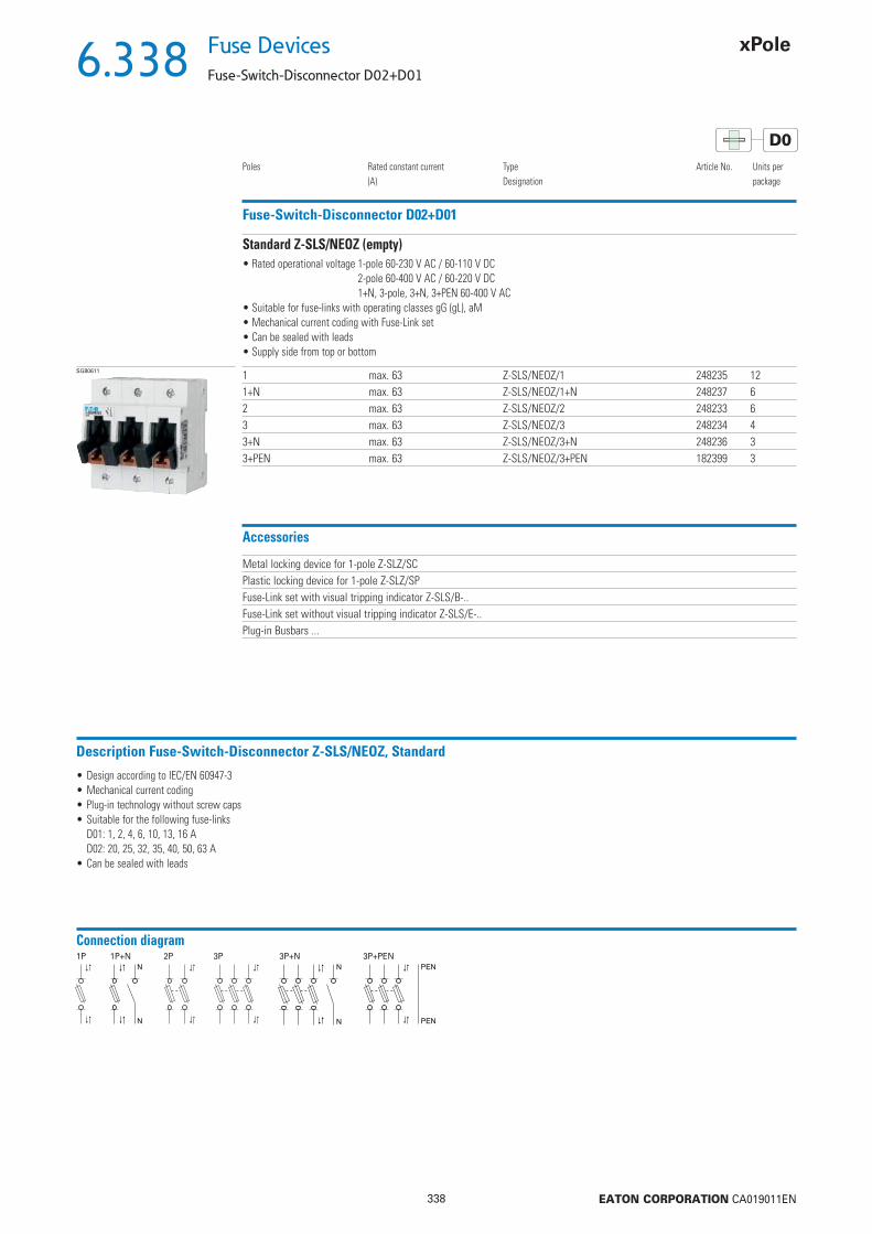
6.338
338 EATON CORPORATION CA019011EN
Fuse Devices
Fuse-Switch-Disconnector D02+D01
D0
Fuse-Switch-Disconnector D02+D01
Poles Rated constant current(A)
TypeDesignation
Article No. Units perpackage
SG80611 1 max. 63 Z-SLS/NEOZ/1 248235 121+N max. 63 Z-SLS/NEOZ/1+N 248237 62 max. 63 Z-SLS/NEOZ/2 248233 63 max. 63 Z-SLS/NEOZ/3 248234 43+N max. 63 Z-SLS/NEOZ/3+N 248236 33+PEN max. 63 Z-SLS/NEOZ/3+PEN 182399 3
• Rated operational voltage 1-pole 60-230 V AC / 60-110 V DC2-pole 60-400 V AC / 60-220 V DC1+N, 3-pole, 3+N, 3+PEN 60-400 V AC
• Suitable for fuse-links with operating classes gG (gL), aM• Mechanical current coding with Fuse-Link set• Can be sealed with leads• Supply side from top or bottom
Standard Z-SLS/NEOZ (empty)
Accessories
Metal locking device for 1-pole Z-SLZ/SCPlastic locking device for 1-pole Z-SLZ/SPFuse-Link set with visual tripping indicator Z-SLS/B-..Fuse-Link set without visual tripping indicator Z-SLS/E-..Plug-in Busbars ...
Description Fuse-Switch-Disconnector Z-SLS/NEOZ, Standard
• Design according to IEC/EN 60947-3• Mechanical current coding• Plug-in technology without screw caps• Suitable for the following fuse-links
D01: 1, 2, 4, 6, 10, 13, 16 AD02: 20, 25, 32, 35, 40, 50, 63 A
• Can be sealed with leads
Connection diagram1P 1P+N 2P 3P 3P+N 3P+PEN
PEN
PEN

6.339
339 EATON CORPORATION CA019011EN
Fuse DevicesFuse-Switch-Disconnector D02+D01
D0
Technical DataZ-SLS/NEOZ
ElectricalNumber of poles 1P, 1P+N, 2P, 3P, 3P+NRated operational voltage Ue
AC 1P, 1P+N 230 V 2P, 3P, 3P+N 400 VDC 1P bis 110 V 2P bis 220 V
Rated operational current Ie 63 ARated constant current Iu 63 AConditional rated short circuit current 50 kAr.m.s.
Utilization category AC 22B, DC 21BOvervoltage category IVRated peak withstand voltage Uimp 6 kVPower loss per current path Ie
L1, L2, L3 0.5 WN 1 W
Power loss per current path with fuse-link Ie L1, L2, L3 6.6 WMax. permissible power loss of fuse-links 5.5 WMechanicalFrame size 45 mmDevice height 86 mmDevice width 27 mm per pole (1.5MU)Weight
1P 113 g1P+N 225 g2P 224 g3P 450 g3P+N 472 g
Mounting Quick fastening on DIN rail according to IEC/EN 60715Degree of protection (behind front plate) IP20CUpper and lower terminals lift terminalsTerminal capacity 1.5-35 mm2
Tightening torque of terminal screws max. 4 NmTemperature range
Ambient air -25 to +40 °C, on 24h average +35 °CStorage -25 to +60 °C
Temperature rise limitsTerminals +70 °KManual operating means +25 °KParts intended to be touched +40 °KParts need not to be touched +50 °K
Flame class V0, glowing wire test 960 °CPollution degree 3Comparative tracking index CTI 600
Dimensions (mm)

6.340
340 EATON CORPORATION CA019011EN
Fuse Devices
Fuse-Switch-Disconnector D02+D01
D0
Examples
Terminal capacity Terminal capacity
Terminal capacity
Terminal capacity

6.341
341 EATON CORPORATION CA019011EN
Fuse DevicesFuse-Switch-Disconnector D02+D01
D0
Fuse-Switch-Disconnector D02+D01
Poles Rated constant current(A)
TypeDesignation
Article No. Units perpackage
SG80711 1pole 10 Z-SLS/CEK10/1 272587 121pole 16 Z-SLS/CEK16/1 263135 121pole 25 Z-SLS/CEK25/1 263136 123pole 16 Z-SLS/CEK16/3 248243 43pole 25 Z-SLS/CEK25/3 248244 43pole 35 Z-SLS/CEK35/3 248245 43pole 40 Z-SLS/CEK40/3 150687 43pole 50 Z-SLS/CEK50/3 248246 43pole 63 Z-SLS/CEK63/3 263160 4
• Rated operational voltage 1-pole 60-230 V AC / 60-110 V DC3-pole 60-400 V AC
• Fuse carrier with visual tripping indicator and fuses inclusive• Mechanical current coding with Fuse-Link set• Can be sealed with leads• Supply side from top or bottom
Complete with captive current code Z-SLS/CEK
Accessories
Metal locking device for 1-pole Z-SLZ/SCPlastic locking device for 1-pole Z-SLZ/SPFuse-Link set with visual tripping indicator Z-SLS/B-..Fuse-Link set without visual tripping indicator Z-SLS/E-..Plug-in Busbars ...
Description Fuse-Switch-Disconnector Z-SLS/CEK, complete with captive current code
• Design according to IEC/EN 60947-3• Can be used as main fuse downstream of the meter according to the Technical Connection Rules of the Austrian Power Supply Companies („TAEV“)• Current coding by the manufacturer• Plug-in technology without screw caps• Suitable for the following fuse-links
D01: 10, 16 AD02: 25, 35, 40, 50, 63 A
• Can be sealed with leads• Visual tripping indicator included
Connection diagram1P 3P
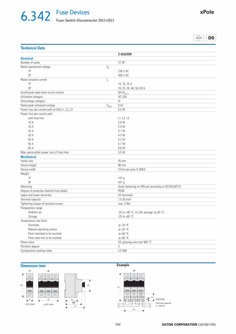
6.342
342 EATON CORPORATION CA019011EN
Fuse Devices
Fuse-Switch-Disconnector D02+D01
D0
Technical DataZ-SLS/CEK
ElectricalNumber of poles 1P, 3PRated operational voltage Ue
1P 230 V AC3P 400 V AC
Rated constant current Iu1P 10, 16, 25 A3P 16, 25, 35, 40, 50, 63 A
Conditional rated short circuit current 50 kAr.m.s.
Utilization category AC 22BOvervoltage category IVRated peak withstand voltage Uimp 6 kVPower loss per current path at 63A L1, L2, L3 0.5 WPower loss per current path
with fuse-link L1, L2, L310 A 2.0 W16 A 2.5 W25 A 3.7 W35 A 4.3 W40 A 5.2 W50 A 5.7 W63 A 6.6 W
Max. permissible power loss of fuse-links 5.5 WMechanicalFrame size 45 mmDevice height 86 mmDevice width 27mm per pole (1.5MU)Weight
1P 147 g3P 441 g
Mounting Quick fastening on DIN rail according to IEC/EN 60715Degree of protection (behind front plate) IP20CUpper and lower terminals lift terminalsTerminal capacity 1.5-35 mm2
Tightening torque of terminal screws max. 4 NmTemperature range
Ambient air -25 to +40 °C, on 24h average +35 °CStorage -25 to +60 °C
Temperature rise limitsTerminals +70 °KManual operating means +25 °KParts intended to be touched +40 °KParts need not to be touched +50 °K
Flame class V0, glowing wire test 960 °CPollution degree 3Comparative tracking index CTI 600
Dimensions (mm)
Terminal capacity
Example

6.343
343 EATON CORPORATION CA019011EN
Fuse DevicesFuse-Switch-Disconnector D02+D01
D0
Fuse-Switch-Disconnector D02+D01
Poles Rated constant current(A)
TypeDesignation
Article No. Units perpackage
SG80911 1+HS max. 63 Z-SLK/NEOZ/1 248238 62+HS max. 63 Z-SLK/NEOZ/2 248239 43+HS max. 63 Z-SLK/NEOZ/3 248240 33+N+HS max. 63 Z-SLK/NEOZ/3+N 248241 2
• Rated operational voltage 1-pole 60-230 V AC / 60-110 V DC2-pole 60-400 V AC / 60-220 V DC1+N, 3-pole, 3+N 60-400 V AC
• Mechanical current coding with Fuse-Link set• Can be sealed with leads• Supply side from top or bottom
With fuse monitoring Z-SLK/NEOZ (empty)
Accessories
Metal locking device for 1-pole Z-SLZ/SCPlastic locking device for 1-pole Z-SLZ/SPFuse-Link set with visual tripping indicator Z-SLS/B-..Fuse-Link set without visual tripping indicator Z-SLS/E-..Plug-in Busbars ...
Description Fuse-Switch-Disconnector Z-SLK/NEOZ, with fuse monitoring
• Design according to IEC/EN 60947-3• Fuse monitoring by relay contact• Mechanical current coding• Plug-in technology without screw caps• Suitable for the following fuse-links
D01: 1, 2, 4, 6, 10, 13, 16 AD02: 20, 25, 32, 35, 40, 50, 63 A
• Can be sealed with leads• Other AC/DC voltages requires special types
Connection diagram1P 2P 3P 3P+N

6.344
344 EATON CORPORATION CA019011EN
Fuse Devices
Fuse-Switch-Disconnector D02+D01
D0
Technical DataZ-SLK/NEOZ
ElectricalNumber of poles 1P, 1P+N, 2P, 3P, 3P+NRated operational voltage Ue
AC 1P, 1P+N 60-230 V 2P, 3P, 3P+N 60-400 VDC 1P 60-110 V 2P 60-220 V
Rated operational current Ie 63 ARated constant current Iu 63 AConditional rated short circuit current 50 kAr.m.s.Utilization category AC 22B, DC 21BOvervoltage category IVRated peak withstand voltage Uimp 6 kVPower loss per current path Ie
L1, L2, L3 0.5 WN 1 W
Power loss per current path with fuse-link Ie L1, L2, L3 6.6 WMax. permissible power loss of fuse-links 5.5 WAuxiliary Switch 1 NO 5 A / 250 V ACRelay Component electrical componentsRated operational voltage range 24-250 V AC/DCRated operational voltage tolerance ±10%Power consumption 1 VAFrequency 16.67; 50-60 HzFunction display
Line voltage 1 LED greenTrouble 1 LED red
Duty 100%Responding delay approx. 100 ms - 1sReset time 1 sRelay contacts 2 CO, 5 A / 250 V ACAuxiliary switch rated impulse withstand voltage 4 kVOvervoltage category IIIMechanicalFrame size 45 mmDevice height 86 mmDevice width 27 mm/pole (1.5MU) + 27 mmWeight
1P 224 g2P 345 g3P 450 g3P+N 590 g
Mounting Quick fastening on DIN rail according to IEC/EN 60715Degree of protection (behind front plate) IP20CUpper and lower terminals lift terminalsTerminal capacity 1.5-35 mm2
Tightening torque of terminal screws max. 4 NmTemperature range
Ambient air -25 to +40 °C, on 24h average +35 °CStorage -25 to +60 °C
Temperature rise limitsTerminals +70 °KManual operating means +25 °KParts intended to be touched +40 °KParts need not to be touched +50 °K
Flame class V0, glowing wire test 960 °CPollution degree 3Comparative tracking index CTI 600Relay Component mechanical componentsUpper and lower terminals lift terminalsTerminal capacity
solid 0.14-4 mm2
fi ne-wire 0.14-2.5 mm2
Tightening torque of terminal screws 0.5-0.7 Nm

6.345
345 EATON CORPORATION CA019011EN
Fuse DevicesFuse-Switch-Disconnector D02+D01
D0
Dimensions (mm)
Simplifi ed diagram
13
14
21
A1
24 - 250 V AC/DC
ResetU
A2
3124 3422 32
Z-SLK1 ... 63 A
Function - Switch position Relay - Fuse monitoring
Uv
24 21 22
34 31 32
24 21 22
34 31 32
Uv
Uv
UvUv
24 21 22
34 31 32
Uv . . . Supply voltage relay

6.346
346 EATON CORPORATION CA019011EN
Fuse Devices
Fuse-Switch-Disconnector D02+D01
D0
Fuse-Link sets complete Z-SLS/B, Z-SLS/E
Rated current(A)
TypeDesignation
Article No. Units perpackage
SG81211 1 Z-SLS/B-1A 268983 1 / 122 Z-SLS/B-2A 268984 1 / 124 Z-SLS/B-4A 268985 1 / 126 Z-SLS/B-6A 268986 1 / 1210 Z-SLS/B-10A 268987 1 / 1213 Z-SLS/B-13A 289972 1 / 1216 Z-SLS/B-16A 268988 1 / 1220 Z-SLS/B-20A 268989 1 / 1225 Z-SLS/B-25A 268990 1 / 1232 Z-SLS/B-32A 289973 1 / 1235 Z-SLS/B-35A 268991 1 / 1240 Z-SLS/B-40A 289974 1 / 1250 Z-SLS/B-50A 268992 1 / 1263 Z-SLS/B-63A 268993 1 / 12
• Rated operational voltage 60-400 V AC
With visual tripping indicator Z-SLS/B
• For Z-SLS/NEOZ, Z-SLS/CEK, Z-SLK/NEOZ• 1 set consists of 3 fuse-links, 3 gauge-pieces, 1 plastic box in the color of the visual tripping indicator
- to snap on DIN rail
1 Z-SLS/B/24-1A 268994 1 / 122 Z-SLS/B/24-2A 268995 1 / 124 Z-SLS/B/24-4A 268996 1 / 126 Z-SLS/B/24-6A 268997 1 / 1210 Z-SLS/B/24-10A 268998 1 / 1213 Z-SLS/B/24-13A 289975 1 / 1216 Z-SLS/B/24-16A 268999 1 / 1220 Z-SLS/B/24-20A 269000 1 / 1225 Z-SLS/B/24-25A 269001 1 / 1232 Z-SLS/B/24-32A 289976 1 / 1235 Z-SLS/B/24-35A 269002 1 / 1240 Z-SLS/B/24-40A 289977 1 / 1250 Z-SLS/B/24-50A 269003 1 / 1263 Z-SLS/B/24-63A 269004 1 / 12
• Rated operational voltage 24-60 V AC / V DC
With visual tripping indicator Z-SLS/B
2 Z-SLS/E-2A 263147 1 / 124 Z-SLS/E-4A 263148 1 / 126 Z-SLS/E-6A 269005 1 / 1210 Z-SLS/E-10A 269006 1 / 1213 Z-SLS/E-13A 289978 1 / 1216 Z-SLS/E-16A 269007 1 / 1220 Z-SLS/E-20A 269008 1 / 1225 Z-SLS/E-25A 269009 1 / 1232 Z-SLS/E-32A 289979 1 / 1235 Z-SLS/E-35A 269010 1 / 1240 Z-SLS/E-40A 289990 1 / 1250 Z-SLS/E-50A 269011 1 / 1263 Z-SLS/E-63A 269012 1 / 12
• Rated operational voltage 400 V AC, 220 V DC
Without visual tripping indicatorZ-SLS/E

6.347
347 EATON CORPORATION CA019011EN
Fuse DevicesFuse-Switch-Disconnector D02+D01
D0
Description Fuse-Link sets complete Z-SLS/B, Z-SLS/E
• Fuse-Links with fl ashing function (Z-SLS/B) in case of disconnection• Fuse-Links without fl ashing function (Z-SLS/E) upon enquiry, not on stock• Supplied as a set with 3 fuse-links and 3 gauge-pieces in plastic box of different colours which can be mounted onto DIN rail.• Dimensions of plastic box:
Frame size 45 mmDepth 75 mmWidth 54 mm
Connection diagram
Technical DataZ-SLS/B, Z-SLS/E
ElectricalOperating class gG (gL)Rated voltage
Z-SLS/B/24 24 - 60 V AC, 24 - 60 V DCZ-SLS/B 60 - 400 V ACZ-SLS/E 400 V AC, 220 V DC
Test voltage 5 kVMechanicalSize
D01 1, 2, 4, 6, 10, 13, 16 AD02 20, 25, 32, 35, 40, 50, 63 A
Characteristics
Time/current characteristics of D0-Fuse-Links 2 ... 63A gG(gL) Let-through characteristics of D0-Fuse-Links 2 ... 63A gG(gL)
310
210
110
010
-110
-210
-310
2 41
10 2 42
10 2 43
10 2 44
10
Schm
elz
ze
ittin
s
Unbeeinflusster Strom I in AP
Nennstrom I in AN2 4 6 10 16 20 25 35 50 63
2I 2P I 2P
20
10
4
2
1
0,4
0,2
0,1
0,1 0,2 0,4 1 2 4 10 20 100
Kurzschlussstrom I in kAP
Ne
nn
str
om
Iin
AN
2
4
6
10
16
20
25
35
50
63
Du
rch
lassstr
om
Iin
kA
D
ß
Mtgrö
tem
Gle
ihst
rom
glie
d
i
c
One
Gle
ichst
rom
glie
d
h
Möglic
he
Sto
ßku
rzsc
hlu
ssst
röm
e
Prospective current IP in A
Vir
tual
pre
-arc
ing
time
t in
s
Let-
thro
ugh
curr
ent I
D in
kA
Prospective short-circuit current IP in kA
Rat
ed c
urre
nt I N
in APo
ssibl
e sho
rt-cir
cut p
eak c
urre
nts
With la
rgest
direc
t curr
ent c
ompo
nent
Withou
t dire
ct curr
ent co
mponen
t

6.348
348 EATON CORPORATION CA019011EN
Fuse Devices
Fuse-Switch-Disconnector D02+D01
D0
Solid-link Set complete Z-SLS/TR-SET
Rated current(A)
TypeDesignation
Article No. Units perpackage
SG81311 63 Z-SLS/TR-SET 100660 1 / 12
• For Z-SLS/NEOZ, Z-SLK/NEOZ, Z-SLS/CEK• 1 set consists of 3 solid-link inserts, 3 gauge-pieces, 1 plastic box to be snapped onto DIN rail• By installing this set, the fuse-switch-disconnector is converted into a switch-disconnector
Description Solid-link Set complete Z-SLS/TR-SET
• Supplied as a set with 3 solid-links inserts and 3 gauge-pieces in plastic box which can be mounted onto DIN rail.• Dimensions of plastic box:
Frame size 45 mmDepth 75 mmWidth 54 mm
Connection diagram
Technical DataZ-SLS/TR-SET
ElectricalRated voltage 400 V ACRated constant current Iu 63 ATest voltage 5 kVMechanicalSize D02 63 A
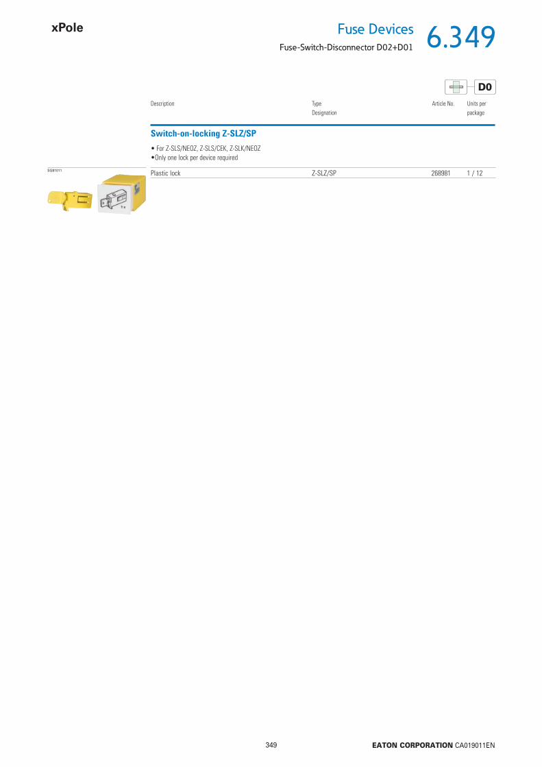
6.349
349 EATON CORPORATION CA019011EN
Fuse DevicesFuse-Switch-Disconnector D02+D01
D0
Switch-on-locking Z-SLZ/SP
Description TypeDesignation
Article No. Units perpackage
SG81011 Plastic lock Z-SLZ/SP 268981 1 / 12
• For Z-SLS/NEOZ, Z-SLS/CEK, Z-SLK/NEOZ•Only one lock per device required

6.350
350 EATON CORPORATION CA019011EN
Fuse Devices
Fuse-Switch-Disconnector D02+D01
D0
Fuse-Switch-Disconnector D02+D01
Poles Rated constant current(A)
TypeDesignation
Article No. Units perpackage
SG80811 1 max. 63 Z-SLS/CB/1 248247 121+N max. 63 Z-SLS/CB/1+N 167282 62 max. 63 Z-SLS/CB/2 248248 63 max. 63 Z-SLS/CB/3 248249 43+N max. 63 Z-SLS/CB/3+N 167283 3
With visual tripping indicator Z-SLS/CB - Current coding by cartridge-ring adapter inserts
Accessories
Fuse-Links Z-D0./SE-..Cartridge-ring adapter inserts D01 Z-D02-D01/PE-..Cartridge-ring adapter inserts D02 Z-D02/PE-..Adapter Spring D01 Z-SLS/CB-HF see chapter Accessories Fuse Devices
Description Fuse-Switch-Disconnector with visual tripping indicator Z-SLS/CB - Current coding by cartridge-ring adapter inserts
• Design according to IEC/EN 60947-3• Current coding by means of cartridge-ring adapter inserts• Visual tripping indicator is fl ashing• Suitable for the following fuse-links
D01: 2, 4, 6, 10, 13, 16 A with cartridge-ring adapter insert Z-D02-D01/PE-.. and Adapter Spring Z-SLS/CB-HF D02: 20, 25, 32, 35, 40, 50, 63 A• Can be sealed with leads
Connection diagram
Dimensions (mm)
Poles Dimension a [mm]1P 271+N 542P 543P 813+N 108

6.351
351 EATON CORPORATION CA019011EN
Fuse DevicesFuse-Switch-Disconnector D02+D01
D0
Technical DataZ-SLS/CB
ElectricalNumber of poles 1P, 1+N, 2P, 3P, 3+NRated operational voltage Ue
1P, 1P+N 230 V AC2P, 3P, 3P+N 400 V AC
Rated operational current Ie 63 ARated constant current Iu 63 AConditional rated short circuit current 50 kAr.m.s.
Utilization category AC 22BOvervoltage category IVRated peak withstand voltage Uimp 6 kVPower loss per current path Ie 0.5 WPower loss per current path with fuse-link Ie 7.5 WMechanicalFrame size 45 mmDevice height 86 mmDevice width 27 mm per pole (1.5MU)Weight
1P 120 g1P+N 230 g2P 230 g3P 350 g3P+N 448 g
Mounting Quick fastening on DIN rail according to IEC/EN 60715Degree of protection IP20Upper and lower terminals lift terminalsTerminal capacity 1.5-35 mm2
Tightening torque of terminal screws max. 4 NmTemperature range -25 to +60 °CFlame class V0, glowing wire test 960 °CPollution degree 3Comparative tracking index CTI 600
Examples
Terminal capacityTerminal capacity
Terminal capacity

6.352
352 EATON CORPORATION CA019011EN
Fuse Devices
Fuse-Switch-Disconnector D02+D01
D0
Adapter Spring Z-SLS/CB-HF
Size TypeDesignation
Article No. Units perpackage
wa_sg02712 D01 Z-SLS/CB-HF 263154 12 / 288
• For Z-SLS/CB/. for the use of fuse-links size D01
Double Terminal Z-SLZ/KL
Description TypeDesignation
Article No. Units perpackage
SG60212 Terminal 2 x 3x35 mm2 Z-SLZ/KL 268982 15
• For Z-SLS/NEOZ, Z-SLS/CEK, Z-SLK/NEOZ
Accessories for Z-SLS
For busbar blocks and feed terminals refer to the technical part, fuse-switch-disconnector, and ordering part, busbar systems.
Terminal capacity

6.353
353 EATON CORPORATION CA019011EN
Fuse DevicesSwitch-Disconnector-Fuse D02+D01
D0 C
Switch-Disconnector-Fuse D02+D01
Poles Rated constant current(A)
TypeDesignation
Article No. Units perpackage
SG80711 3 max. 63 D02-LTS/63-3 114320 33 max. 63 D02-LTS/63-3-HK 114322 33N max. 63 D02-LTS/63-3N 114321 3
With visual tripping indicator D02-LTS
Accessories for D02-LTS
D0 Fuse-Links Z-D0./SE-...Cartridge-ring adapter inserts D01: Z-D02-D01/PE-...
D02: Z-D02/PE-...Adapter Spring Z-D02-LTS-HF (scope of delivery)
C Fuse-Links Z-C10/SE-...Adapter Spring Z-D02-LTS-HF (scope of delivery)
Siehe Fuse Devices Accessories
Description Switch-Disconnector-Fuse D02-LTS - Current coding by cartridge-ring adapter inserts
• Design according to IEC/EN 60947-3• Current coding by means of cartridge-ring adapter inserts• Visual tripping indicator is fl ashing• Suitable for fuse-links with operating classes gG (gL), aM
D01: 2, 4, 6, 10, 13, 16 A with cartridge-ring adapter insert Z-D02-D01/PE-.. and Adapter Spring Z-D02-LTS-HF D02: 20, 25, 32, 35, 50, 63 A Cylindrical 10x38 up to 32 A with adapter spring Z-D02-LTS-HF• Can be sealed with leads
• Rated operational voltage 400 V AC• Suitable for fuse-links with operating classes gG (gL), aM• Only 4MU in width, busbar compatible to Xpole switchgear• Current coding by cartridge-ring adapter inserts• Can be sealed with leads• Supply side from top or bottom• Version with Auxiliary Switch D02-LTS/63-3-HK• Delivered with Adapter Springs for fuse-links D01 or cylindrical fuse-links 10x38
SG81811 16 32
D02-D01C 10x38
Z-D02-LTS-HF 114323 12 / 288
Adapter Spring Z-D02-LTS-HF• To accomodate D01 fuse-links or cylindrical fuse-links 10x38 in the Switch-disconnetorfuse D02-LTS/63...
Max. Rated operational current Ie (A)
Size TypeDesignation
Article No. Units perpackage
Connection diagram
14
13
6
5
4
3
2
1
3P 3P+N 3P+HK8
7
6
5
4
3
2
1
6
5
4
3
2
1
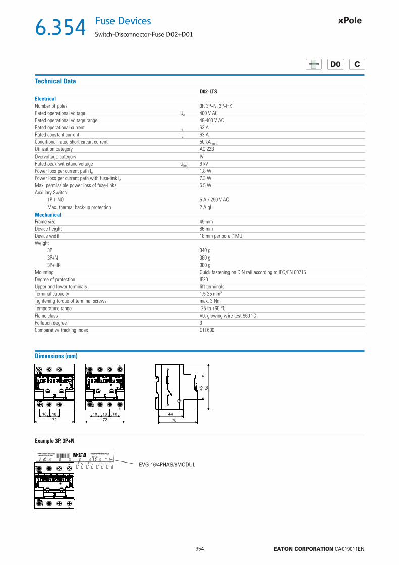
6.354
354 EATON CORPORATION CA019011EN
Fuse Devices
Switch-Disconnector-Fuse D02+D01
D0 C
Technical DataD02-LTS
ElectricalNumber of poles 3P, 3P+N, 3P+HKRated operational voltage Ue 400 V ACRated operational voltage range 48-400 V ACRated operational current Ie 63 ARated constant current Iu 63 AConditional rated short circuit current 50 kAr.m.s.
Utilization category AC 22BOvervoltage category IVRated peak withstand voltage Uimp 6 kVPower loss per current path Ie 1.8 WPower loss per current path with fuse-link Ie 7.3 WMax. permissible power loss of fuse-links 5.5 WAuxiliary Switch
1P 1 NO 5 A / 250 V ACMax. thermal back-up protection 2 A gL
MechanicalFrame size 45 mmDevice height 86 mmDevice width 18 mm per pole (1MU)Weight
3P 340 g3P+N 380 g3P+HK 380 g
Mounting Quick fastening on DIN rail according to IEC/EN 60715Degree of protection IP20Upper and lower terminals lift terminalsTerminal capacity 1.5-25 mm2
Tightening torque of terminal screws max. 3 NmTemperature range -25 to +60 °CFlame class V0, glowing wire test 960 °CPollution degree 3Comparative tracking index CTI 600
Dimensions (mm)N
N
Example 3P, 3P+N
4015082914752
N
N
EVG-16/4PHAS/8MODUL

6.355
355 EATON CORPORATION CA019011EN
Fuse DevicesFuse-Disconnector (empty)
Fuse-Disconnector (empty)
Poles Size TypeDesignation
Article No. Units perpackage
SG81211
1 10x38 Z-SH/1 263876 12 / 1201+N 10x38 Z-SH/1N 263877 12 / 1202 10x38 Z-SH/2 263878 6 / 603 10x38 Z-SH/3 263879 4 / 403+N 10x38 Z-SH/3N 263880 4 / 40
For industry Z-SH
• For cylindrical fuse-links• The visual tripping indicator indicates the tripped fuse-link• Can be sealed with leads
C
Without visual tripping indicator
SG36412
1 10x38 Z-SHL/1 263883 12 / 1201+N 10x38 Z-SHL/1N 263884 12 / 1202 10x38 Z-SHL/2 263885 6 / 603 10x38 Z-SHL/3 263886 4 / 403+N 10x38 Z-SHL/3N 263887 4 / 40
With visual tripping indicator
Rated current(A)
Size TypeDesignation
Article No. Units perpackage
SG00412
10 8.5x23 Z-SI/10/1 263889 12 / 12016 10.3x25.8 Z-SI/16/1 263890 12 / 12020 8.5x31.5 Z-SI/20/1 263891 12 / 12025 10.3x31.5 Z-SI/25/1 263892 12 / 12032 10.3x38 Z-SI/32/1 263893 12 / 120
For household applications Z-SI, 1pole
Without visual tripping indicator
20 8.5x31.5 Z-SIL/20/1 263901 12 / 12025 10.3x31.5 Z-SIL/25/1 263902 12 / 12032 10.3x38 Z-SIL/32/1 263903 12 / 120
With visual tripping indicator
SG53912
10 8.5x23 Z-SI/10/1N 263894 12 / 12016 10.3x25.8 Z-SI/16/1N 263895 12 / 12020 8.5x31.5 Z-SI/20/1N 263896 12 / 12025 10.3x31.5 Z-SI/25/1N 263897 12 / 12032 10.3x38 Z-SI/32/1N 263898 12 / 120
For household applications Z-SI, 1+Npole
Without visual tripping indicator
20 8.5x31.5 Z-SIL/20/1N 263938 12 / 12025 10.3x31.5 Z-SIL/25/1N 263939 12 / 12032 10.3x38 Z-SIL/32/1N 263940 12 / 120
With visual tripping indicator
Accessories for Z-SH, Z-SI
Fuse-Links Z-C/SE...see chapter Accessories Fuse Devices

6.356
356 EATON CORPORATION CA019011EN
Fuse Devices
Fuse-Disconnector (empty)
C
Description Fuse-Disconnector for Industrial Applications Z-SH
• Design according to IEC/EN 60947-3• Design
without visual tripping indicator Z-SHwith visual tripping indicator Z-SHL
• Can be sealed with leads• Supplied without fuse-links
Technical DataZ-SH
ElectricalNumber of poles 1P, 1P+N, 2P, 3P, 3P+NRated voltage
1P, 1P+N 230 V AC2P, 3P, 3P+N 400 V AC
Rated operational current Ie 32 AConditional short-circuit current 10 kAr.m.s.
Utilization category AC 20BOvervoltage category IVRated peak withstand voltage Uimp 4 kVFuse-Links 10, 16, 20, 25, 32 A
Operating class gG(gL) / aMMax. Power loss per current path 3.2 W
MechanicalFrame size 45 mmDevice height 80 mmDevice width according to dimensioned drawingWeight Z-SH Z-SHL
1P 74 g 76 g1P+N 84 g 86 g2P 156 g 158 g3P 234 g 236 g3P+N 244 g 246 g
Mounting Quick fastening on DIN rail according to IEC/EN 60715Degree of protection (built-in) IP20 (IP40)Upper and lower terminals lift terminalsTerminal capacity 1.5-10 mm2
Tightening torque of terminal screws max. 2 NmTemperature range -25 to +60 °CDimensions of fuse-link 10.3 x 38 mm
Connection diagramZ-SH/3N
Dimensions (mm)
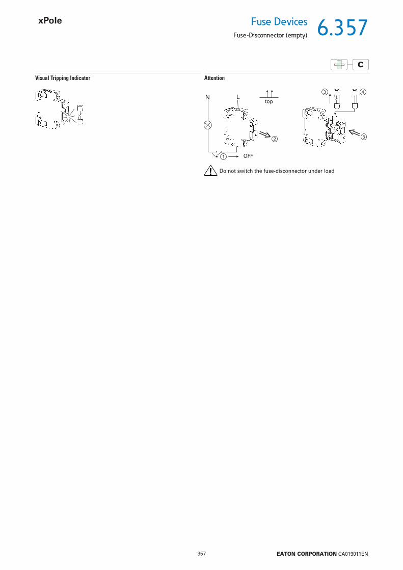
6.357
357 EATON CORPORATION CA019011EN
Fuse DevicesFuse-Disconnector (empty)
C
Visual Tripping Indicator Attention
Do not switch the fuse-disconnector under load
OFF
top

6.358
358 EATON CORPORATION CA019011EN
Fuse Devices
Fuse-Disconnector (empty)
C
Description Fuse-Disconnector for Household Applications Z-SI
• Design according to IEC/EN 60947-3• Design
without visual tripping indicator Z-SIwith visual tripping indicator Z-SIL
• Can be sealed with leads• The open fuse drawer can be secured against re-switch-on by means of a padlock• Supplied without fuse-links
Technical DataZ-SI
ElectricalNumber of poles 1P, 1P+NRated voltage 230 V ACRated operational current Ie 32 AConditional short-circuit current 10 kAr.m.s.
Utilization category AC 20BRated peak withstand voltage Uimp 4 kVFuse-Links 10, 16, 20, 25, 32 A
Operating class gG(gL) / aMMax. Power loss per current path 3.2 W
MechanicalFrame size 45 mmDevice height 80 mmDevice width 17.5 mmWeight Z-SI Z-SIL
1P 74 g 76 g1P+N 84 g 86 g
Mounting Quick fastening on DIN rail according to IEC/EN 60715Degree of protection (built-in) IP20 (IP40)Upper and lower terminals lift terminalsTerminal capacity 1.5-10 mm2
Tightening torque of terminal screws max. 2 NmDimensions of fuse-link
Rated current (A) mm10 8.5 x 2316 10.3 x 25.820 8.5 x 31.525 10.3 x 31.532 10.3 x 38
Connection diagram
Dimensions (mm)
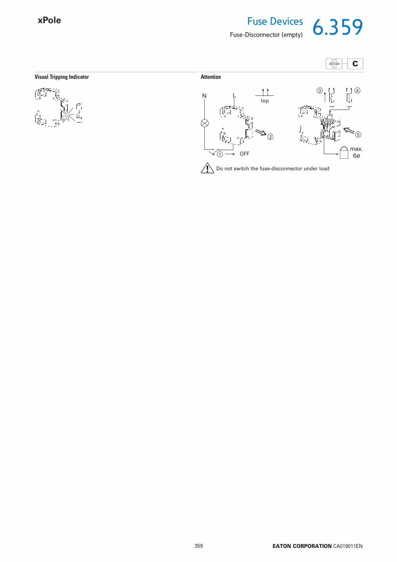
6.359
359 EATON CORPORATION CA019011EN
Fuse DevicesFuse-Disconnector (empty)
C
Visual Tripping Indicator Attention
Do not switch the fuse-disconnector under load
OFF
top
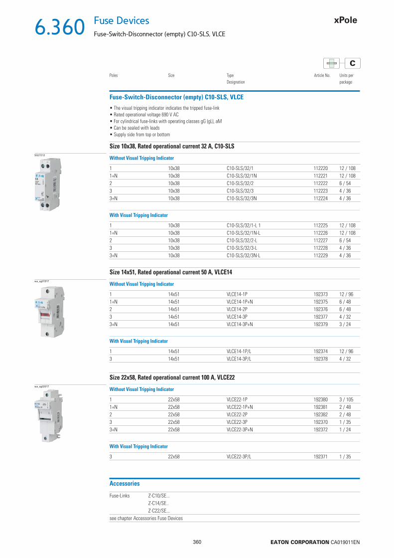
6.360
360 EATON CORPORATION CA019011EN
Fuse Devices
Fuse-Switch-Disconnector (empty) C10-SLS, VLCE
C
Fuse-Switch-Disconnector (empty) C10-SLS, VLCE
Poles Size TypeDesignation
Article No. Units perpackage
SG27212
1 10x38 C10-SLS/32/1 112220 12 / 1081+N 10x38 C10-SLS/32/1N 112221 12 / 1082 10x38 C10-SLS/32/2 112222 6 / 543 10x38 C10-SLS/32/3 112223 4 / 363+N 10x38 C10-SLS/32/3N 112224 4 / 36
Size 10x38, Rated operational current 32 A, C10-SLS
• The visual tripping indicator indicates the tripped fuse-link• Rated operational voltage 690 V AC• For cylindrical fuse-links with operating classes gG (gL), aM• Can be sealed with leads• Supply side from top or bottom
Without Visual Tripping Indicator
1 10x38 C10-SLS/32/1-L 1 112225 12 / 1081+N 10x38 C10-SLS/32/1N-L 112226 12 / 1082 10x38 C10-SLS/32/2-L 112227 6 / 543 10x38 C10-SLS/32/3-L 112228 4 / 363+N 10x38 C10-SLS/32/3N-L 112229 4 / 36
With Visual Tripping Indicator
wa_sg01917
1 14x51 VLCE14-1P 192373 12 / 961+N 14x51 VLCE14-1P+N 192375 6 / 482 14x51 VLCE14-2P 192376 6 / 483 14x51 VLCE14-3P 192377 4 / 323+N 14x51 VLCE14-3P+N 192379 3 / 24
Size 14x51, Rated operational current 50 A, VLCE14
Without Visual Tripping Indicator
1 14x51 VLCE14-1P/L 192374 12 / 963 14x51 VLCE14-3P/L 192378 4 / 32
With Visual Tripping Indicator
wa_sg02017
1 22x58 VLCE22-1P 192380 3 / 1051+N 22x58 VLCE22-1P+N 192381 2 / 482 22x58 VLCE22-2P 192382 2 / 483 22x58 VLCE22-3P 192370 1 / 353+N 22x58 VLCE22-3P+N 192372 1 / 24
Size 22x58, Rated operational current 100 A, VLCE22
Without Visual Tripping Indicator
3 22x58 VLCE22-3P/L 192371 1 / 35
With Visual Tripping Indicator
Accessories
Fuse-Links Z-C10/SE...Z-C14/SE..Z-C22/SE...
see chapter Accessories Fuse Devices
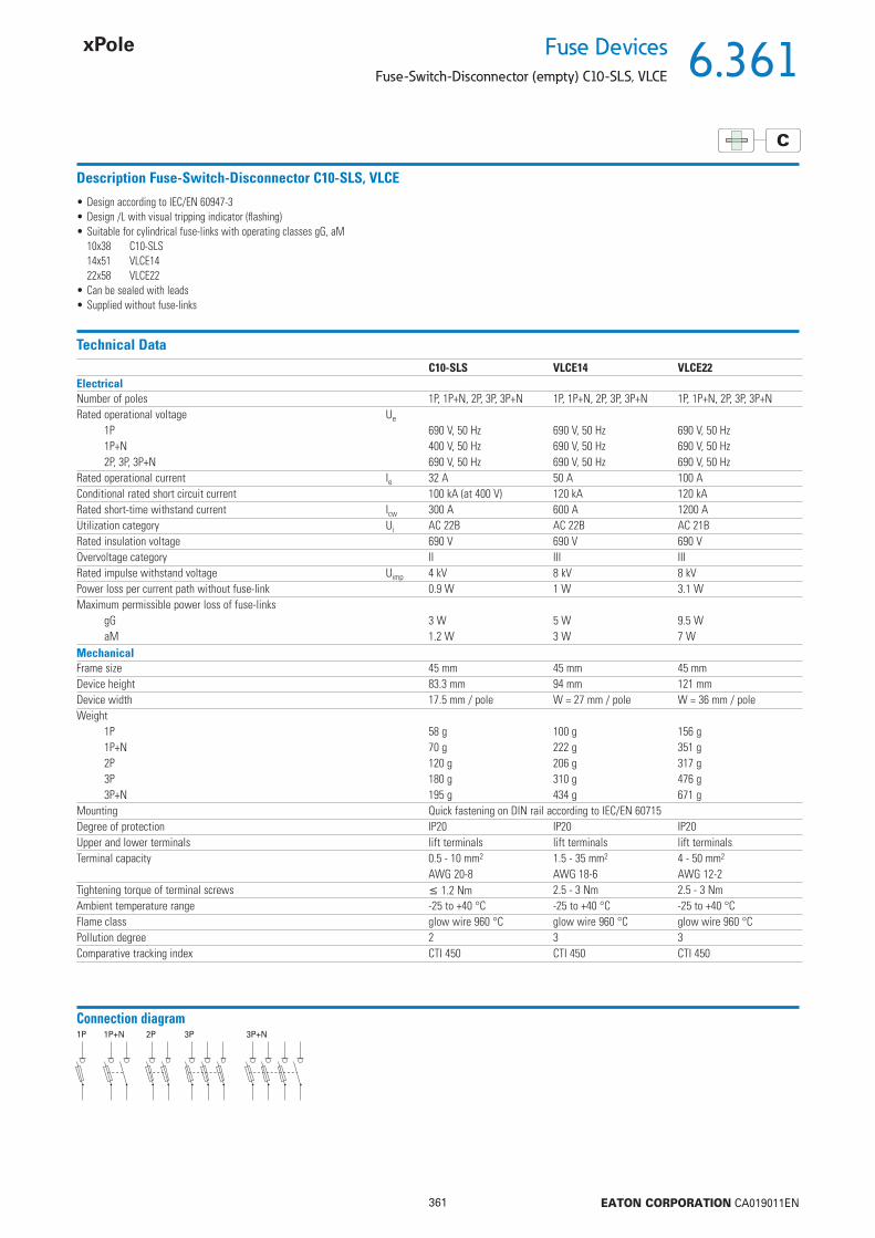
6.361
361 EATON CORPORATION CA019011EN
Fuse DevicesFuse-Switch-Disconnector (empty) C10-SLS, VLCE
C
Description Fuse-Switch-Disconnector C10-SLS, VLCE
• Design according to IEC/EN 60947-3• Design /L with visual tripping indicator (fl ashing)• Suitable for cylindrical fuse-links with operating classes gG, aM
10x38 C10-SLS14x51 VLCE1422x58 VLCE22
• Can be sealed with leads• Supplied without fuse-links
Technical DataC10-SLS VLCE14 VLCE22
ElectricalNumber of poles 1P, 1P+N, 2P, 3P, 3P+N 1P, 1P+N, 2P, 3P, 3P+N 1P, 1P+N, 2P, 3P, 3P+NRated operational voltage Ue
1P 690 V, 50 Hz 690 V, 50 Hz 690 V, 50 Hz1P+N 400 V, 50 Hz 690 V, 50 Hz 690 V, 50 Hz2P, 3P, 3P+N 690 V, 50 Hz 690 V, 50 Hz 690 V, 50 Hz
Rated operational current Ie 32 A 50 A 100 AConditional rated short circuit current 100 kA (at 400 V) 120 kA 120 kARated short-time withstand current Icw 300 A 600 A 1200 AUtilization category Ui AC 22B AC 22B AC 21BRated insulation voltage 690 V 690 V 690 VOvervoltage category II III IIIRated impulse withstand voltage Uimp 4 kV 8 kV 8 kVPower loss per current path without fuse-link 0.9 W 1 W 3.1 WMaximum permissible power loss of fuse-links
gG 3 W 5 W 9.5 WaM 1.2 W 3 W 7 W
MechanicalFrame size 45 mm 45 mm 45 mmDevice height 83.3 mm 94 mm 121 mmDevice width 17.5 mm / pole W = 27 mm / pole W = 36 mm / poleWeight
1P 58 g 100 g 156 g1P+N 70 g 222 g 351 g2P 120 g 206 g 317 g3P 180 g 310 g 476 g3P+N 195 g 434 g 671 g
Mounting Quick fastening on DIN rail according to IEC/EN 60715Degree of protection IP20 IP20 IP20Upper and lower terminals lift terminals lift terminals lift terminalsTerminal capacity 0.5 - 10 mm2 1.5 - 35 mm2 4 - 50 mm2
AWG 20-8 AWG 18-6 AWG 12-2Tightening torque of terminal screws 1.2 Nm 2.5 - 3 Nm 2.5 - 3 NmAmbient temperature range -25 to +40 °C -25 to +40 °C -25 to +40 °CFlame class glow wire 960 °C glow wire 960 °C glow wire 960 °CPollution degree 2 3 3Comparative tracking index CTI 450 CTI 450 CTI 450
Connection diagram1P 1P+N 2P 3P 3P+N

6.362
362 EATON CORPORATION CA019011EN
Fuse Devices
Fuse-Switch-Disconnector (empty) C10-SLS, VLCE
C
Dimensions (mm)C10-SLS VLCE14 VLCE22
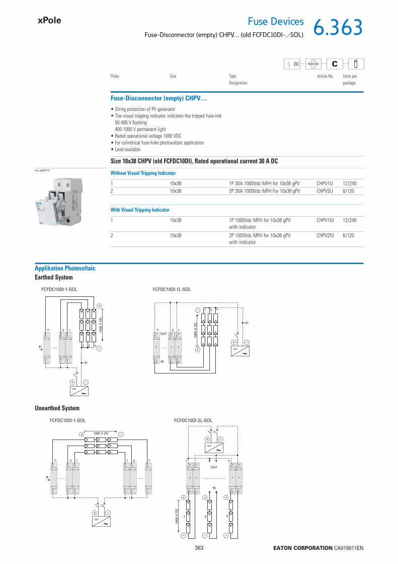
6.363
363 EATON CORPORATION CA019011EN
Fuse DevicesFuse-Disconnector (empty) CHPV… (old FCFDC10DI-..-SOL)
Fuse-Disconnector (empty) CHPV…
Poles Size TypeDesignation
Article No. Units perpackage
wa_sg00210
1 10x38 1P 30A 1000Vdc MFH for 10x38 gPV CHPV1U 12/2402 10x38 2P 30A 1000Vdc MFH For 10x38 gPV CHPV2U 6/120
Size 10x38 CHPV (old FCFDC10DI), Rated operational current 30 A DC
• String protection of PV generator• The visual tripping indicator indicates the tripped fuse-link
50-400 V fl ashing400-1000 V permanent light
• Rated operational voltage 1000 VDC• For cylindrical fuse-links photovoltaic application• Lead-sealable
Without Visual Tripping Indicator
1 10x38 1P 1000Vdc MFH for 10x38 gPV with indicator
CHPV1IU 12/240
2 10x38 2P 1000Vdc MFH for 10x38 gPV with indicator
CHPV2IU 6/120
With Visual Tripping Indicator
CDC
Applikation PhotovoltaicEarthed System
Unearthed System
FCFDC10DI-1-SOL FCFDC10DI-1L-SOL
FCFDC10DI-1-SOL FCFDC10DI-2L-SOL

6.364
364 EATON CORPORATION CA019011EN
Fuse Devices
Fuse-Disconnector (empty) FCFDC10DI-..-SOL
CDC
Description Fuse-Disconnector (empty) FCFDC10DI-..-SOL
• Design according to IEC 60947-1 Ed. 4.0, EN 60947-1:1999+A1:2000+A2:2001IEC 60947-3 Ed. 2.1, EN 60947-3:1999+A1:2001
• Design L with visual tripping indicator (fl ashing)• table for cylindrical fuse-links photovoltaic application 10x38 accoording to IEC 60269, UL284-4• Can be sealed with leads• Supplied without fuse-links
Technical DataFCFDC10DI-..-SOL
ElectricalNumber of poles 1P, 2PRated voltage Ue 1000 V DCRated current Ie 25 AConditional rated short circuit current 10 kAUtilization category DC 20BOvervoltage category IIIRated peak withstand voltage Uimp 6 kVPower loss per current path without fuse-link 0.9 WMaximum permissible power loss of fuse-links 3 WMechanicalFrame size 45 mmDevice height 83.3 mmDevice width 17.5 mm / poleWeight
1P 58 g2P 70 g
Mounting Quick fastening on DIN rail according to IEC/EN 60715Degree of protection IP20Upper and lower terminals lift terminalsTerminal capacity 1.5-10 mm2
AWG 20-8Tightening torque of terminal screws 1.5 NmAmbient temperature range -25 to +40 °CFlame class glow wire 960 °CPollution degree 2Comparative tracking index CTI 450
Connection diagram
1P 2P 1P 2P
FCFDC10DI-.-SOL FCFDC10DI-.L-SOL
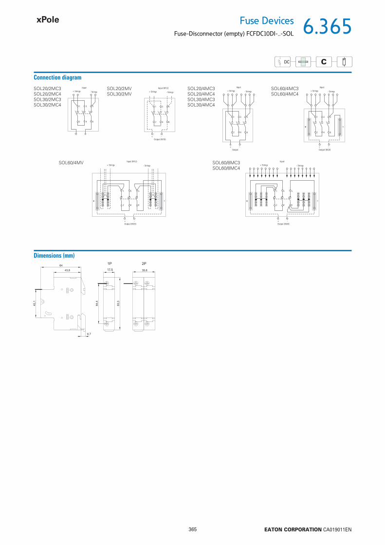
6.365
365 EATON CORPORATION CA019011EN
Fuse DevicesFuse-Disconnector (empty) FCFDC10DI-..-SOL
CDC
Connection diagram
- Strings+ Strings
Input
1 3 5
2 4 6
- Strings+ Strings
Output (M20)
Input
+ -
1
+ -
3 5
2 4 6
- Strings+ Strings
Output
Input
+ -
1 3 5
2 4 6
- Strings+ Strings
Output (M16)
Input (M12)
+ -
1 3 5
2 4 6
SOL20/2MC3SOL20/2MC4SOL30/2MC3SOL30/2MC4
SOL20/2MVSOL30/2MV
SOL20/4MC3SOL20/4MC4SOL30/4MC3SOL30/4MC4
- Strings + Strings
Input (M12)
Output (M20)+ -
+ -
1 3 5
2 4 6
- Strings+ Strings
Input
Output (M20)+ -
+ -
1 3 5
2 4 6
SOL60/4MV SOL60/8MC3SOL60/8MC4
SOL60/4MC3SOL60/4MC4
Dimensions (mm)
17.5
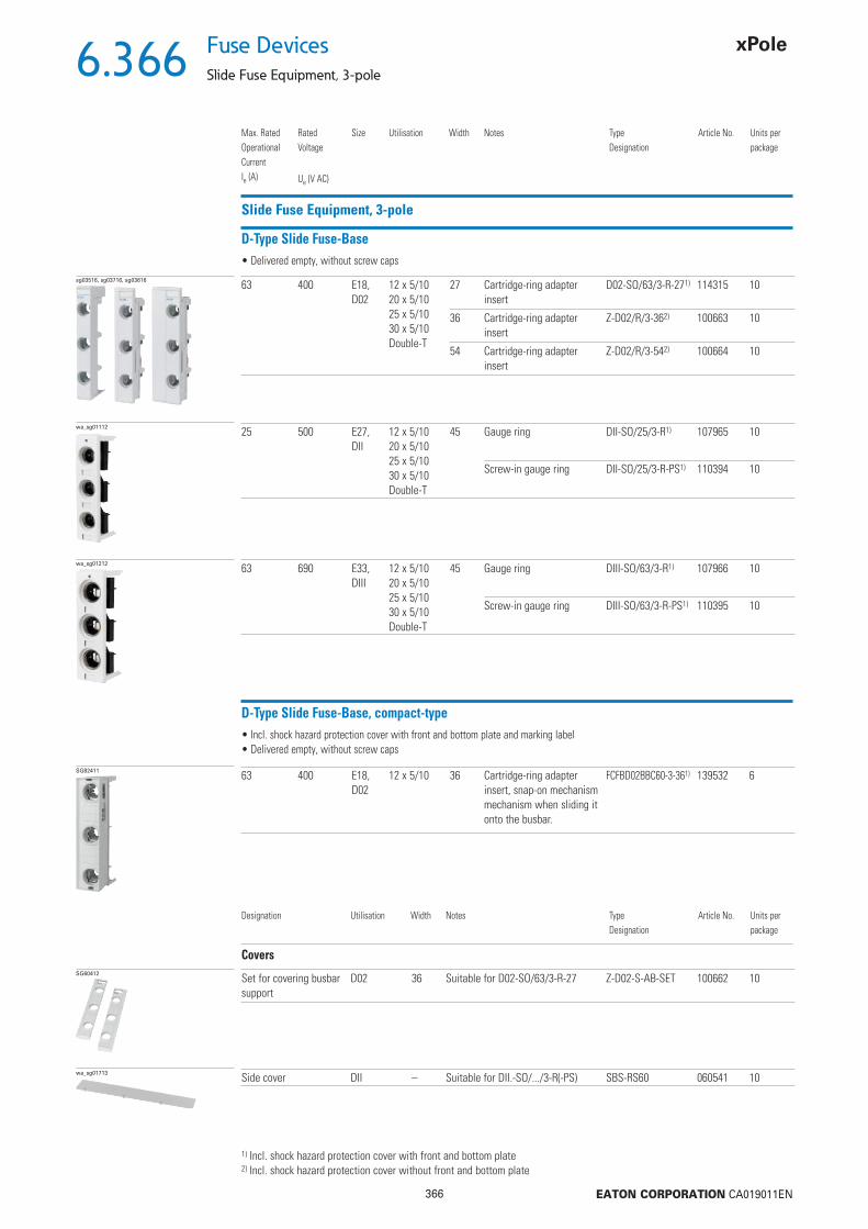
6.366
366 EATON CORPORATION CA019011EN
Fuse Devices
Slide Fuse Equipment, 3-pole
Slide Fuse Equipment, 3-pole
D-Type Slide Fuse-Base
sg03516, sg03716, sg03616 63 400 E18, D02
12 x 5/1020 x 5/1025 x 5/1030 x 5/10Double-T
27 Cartridge-ring adapter insert
D02-SO/63/3-R-271) 114315 10
36 Cartridge-ring adapter insert
Z-D02/R/3-362) 100663 10
54 Cartridge-ring adapter insert
Z-D02/R/3-542) 100664 10
Max. Rated Operational CurrentIe (A)
Rated Voltage
Ue (V AC)
Size Utilisation Width Notes TypeDesignation
Article No. Units perpackage
• Delivered empty, without screw caps
1) Incl. shock hazard protection cover with front and bottom plate2) Incl. shock hazard protection cover without front and bottom plate
wa_sg01112 25 500 E27, DII
12 x 5/1020 x 5/1025 x 5/1030 x 5/10Double-T
45 Gauge ring DII-SO/25/3-R1) 107965 10
Screw-in gauge ring DII-SO/25/3-R-PS1) 110394 10
wa_sg01212 63 690 E33, DIII
12 x 5/1020 x 5/1025 x 5/1030 x 5/10Double-T
45 Gauge ring DIII-SO/63/3-R1) 107966 10
Screw-in gauge ring DIII-SO/63/3-R-PS1) 110395 10
D-Type Slide Fuse-Base, compact-type
SG82411 63 400 E18, D02
12 x 5/10 36 Cartridge-ring adapter insert, snap-on mechanism mechanism when sliding it onto the busbar.
FCFBD02BBC60-3-361) 139532 6
• Incl. shock hazard protection cover with front and bottom plate and marking label• Delivered empty, without screw caps
Designation Utilisation Width Notes TypeDesignation
Article No. Units perpackage
CoversSG60412 Set for covering busbar
supportD02 36 Suitable for D02-SO/63/3-R-27 Z-D02-S-AB-SET 100662 10
wa_sg01713 Side cover DII – Suitable for DII.-SO/.../3-R(-PS) SBS-RS60 060541 10
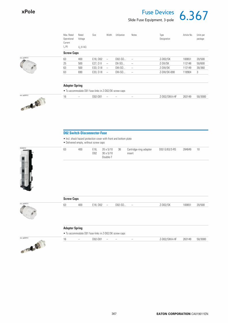
6.367
367 EATON CORPORATION CA019011EN
Fuse DevicesSlide Fuse Equipment, 3-pole
Screw Capswa_sg04013 63 400 E18, D02 – D02-SO... – Z-D02/SK 100651 20/500
25 500 E27, D II – DII-SO... – Z-DII/SK 112148 50/60063 500 E33, D III – DIII-SO... – Z-DIII/SK 112149 30/36063 690 E33, D III – DIII-SO... – Z-DIII/SK-690 118904 3
Max. Rated Operational CurrentIe (A)
Rated Voltage
Ue (V AC)
Size Width Utilisation Notes TypeDesignation
Article No. Units perpackage
Adapter Spring
wa_sg02612 16 – D02-D01 – – – Z-D02/SIKA-HF 263149 50/3000
• To accommodate D01 fuse-links in Z-D02/SK screw caps
D02 Switch-Disconnector-Fuse
SG45912 63 400 E18, D02
20 x 5/1030 x 5/10Double-T
36 Cartridge-ring adapter insert
D02-S/63/3-RS 284649 10
• Incl. shock hazard protection cover with front and bottom plate• Delivered empty, without screw caps
Screw Capswa_sg04013 63 400 E18, D02 – D02-SO... – Z-D02/SK 100651 20/500
Adapter Spring
wa_sg02612 16 – D02-D01 – – – Z-D02/SIKA-HF 263149 50/3000
• To accommodate D01 fuse-links in Z-D02/SK screw caps

6.368
368 EATON CORPORATION CA019011EN
Fuse Devices
Slide Fuse Equipment, 3-pole
Switch-Disconnector-Fuse D02 (+D01) + C
SG82311 63
32
400
400
E18, D02C 10x38
27 12 x 5/1015 x 5/1020 x 5/1025 x 5/1030 x 5/10Double-T
Cartridge-ring adapter insert without auxiliary switch
D02-LTS/63/3-R 114316 3
Cartridge-ring adapter insert with auxiliary switch
D02-LTS/63/3-R-HK 114318 3
Max. Rated Operational CurrentIe (A)
Rated Voltage
Ue (V AC)
Size Width Utilisation Notes TypeDesignation
Article No. Units perpackage
• Visiual tripping indicator is fl ashing• Delivered empty, without cartridge-ring adapter inserts and fuse-links• Delivered with adapter springs for fuse-links D01 or cylindrical fuse-links 10x38• Contact position indicator• Plug-in technique without screw caps• All-pole and hand independent switching of load• Version D02-LTS/63/3-R-HK with incorporated auxliliary switch• Lead-seal- and lockable
3P
SG82211 63
32
400
400
E18, D02C 10x38
27 12 x 5/1015 x 5/1020 x 5/1025 x 5/1030 x 5/10Double-T
Cartridge-ring adapter insert without auxiliary switch
D02-LTS/63/3N-R 114317 3
Cartridge-ring adapter insert with auxiliary switch
D02-LTS/63/3N-R-HK114319 3
3P+N
Accessories for D02-LTS/63..
D0 Fuse-links Z-D0./SE-...Cartridge-ring adapter inserts D01: Z-D02-D01/PE-...
D02: Z-D02/PE-...Adapter spring Z-D02-LTS-HF (scope of delivery)
C Fuse-links Z-C10/SE-...Adapter spring Z-D02-LTS-HF (scope of delivery)
See Fuse Material Accessories
Adapter Spring
SG81811 1632
– D02-D01C 10x38
– – – Z-D02-LTS-HF 114323 12/288
• To accommodate D01 fuse-links or cylindrical fuse-links 10x38 in the Switch-disconnector-fuse D02-LTS/63...

6.369
369 EATON CORPORATION CA019011EN
Fuse DevicesFuse-Switch-Disconnector D02+D01 Technical Data
Technical Data D-Type Slide Fuse-Base
D02-SO/63/3-R-27Z-D02/R/3...
DII-SO/25/3-R(-PS) DIII-SO/63/3-R(-PS)
ElectricalNumber of poles 3 3 3Rated operational voltage Ue 400 V AC 500 V AC 690 V ACRated frequency 40-60 Hz 40-60 Hz 40-60 HzRated operational current Ie 63 A 25 A 63 AConventional thermal current with fuse-links Ith 63 A 25 A 63 ARated duty uninterrupted duty uninterrupted duty uninterrupted dutyRated conditional short-circuit current 50 kAr.m.s 50 kAr.m.s 50 kAr.m.s
Overvoltage category IV III IIIRated impulse withstand voltage Uimp 6 kV 4 kV 4 kVPower loss per current path 0.5 W 0.4 W 3.34 WPower loss of base without fuse-links 1.5 W 1.2 W 10 WMax. permissible power loss of fuse-links 5.5 W 4 W 7 WMechanicalDevice height 201 mm 200 mm 200 mmWidth 27 mm 45 mm 54 mmWeight 150 g 140 g 150 gMounting onto busbars, without drilling or screwing 12x5/10 12x5/10 12x5/10
15x5/10 - -20x5/10 20x5/10 20x5/1025x5/10 25x5/10 25x5/1030x5/10 30x5/10 30x5/10
Degree of protection while operating IP20 IP20 IP20Terminals lift terminals lift terminals lift terminalsTerminal capacity 1.5-35 mm2 1.5-25 mm2 1.5-25 mm2
Tightening torque of terminal screws 3-4 Nm 2.6 Nm 2.6 NmElectrical thread type E18 E27 E33Ambient temperature range -25 to +55 °C -25 to +55 °C *) -25 to +55 °C *)
*) (35 °C normal temperature, at 55 °C with reduced operating current)Pollution degree 3 3 3Climatic resistance: moist heat constant according to IEC 60068-2-78, cyclical according to IEC 60068-2-30
• Design according to IEC/EN 60269-1, VDE 0636 Part 301• Vertical and horizontal mounting possible• Delivered empty, without screw caps

6.370
370 EATON CORPORATION CA019011EN
Fuse Devices
Fuse-Switch-Disconnector D02+D01 Technical Data
Technical Data Busbar-Slide Switch Disconnector with Fuses D02-S/63/3-RS
D02-S/63/3-RSElectricalNumber of poles 3Rated operational voltage Ue 400 V ACRated frequency 40-60 HzRated operational current Ie 63 AConventional thermal current with fuse-links Ith 63 ARated duty uninterrupted dutyRated conditional short-circuit current 50 kAr.m.s
Utilization category AC-23BOvervoltage category IIIRated impulse withstand voltage Uimp 8 kVPower loss per current path 2 W with IePower loss per current path with fuse-link 7.5 W with IeMax. permissible power loss of fuse-links 5.5 WMechanicalDevice height 212 mmWidth 36 mmWeight 260 gMounting onto busbars, without drilling or screwing 20x5/10 mm
30x5/10 mmDegree of protection while operating IP20Terminals lift terminalsTerminal capacity 1.5-25 mm2 CuTightening torque of terminal screws max. 2.6 NmElectrical thread type E18Ambient temperature range -25 to +55 °CPollution degree 3Climatic resistance: moist heat constant according to IEC 60068-2-78, cyclical according to IEC 60068-2-30
• Design according to IEC/EN 60947-3• Vertical and horizontal mounting possible• Delivered empty, without screw caps• Current coding by means of cartridge-ring adapter insert• Suitable for fuse-links
D01: 2, 4, 6, 10, 16 A in combination with cartridge-ring adapter inserts Z-D02-D01/PE-.. and adapter spring Z-D02/SIKA-HF D02: 20, 25, 35, 50, 63 A• Sealable
Connection diagram
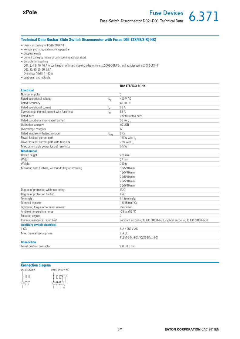
6.371
371 EATON CORPORATION CA019011EN
Fuse DevicesFuse-Switch-Disconnector D02+D01 Technical Data
Technical Data Busbar-Slide Switch Disconnector with Fuses D02-LTS/63/3-R(-HK)
D02-LTS/63/3-R(-HK)ElectricalNumber of poles 3Rated operational voltage Ue 400 V ACRated frequency 40-60 HzRated operational current Ie 63 AConventional thermal current with fuse-links Ith 63 ARated duty uninterrupted dutyRated conditional short-circuit current 50 kAr.m.s
Utilization category AC-22BOvervoltage category IVRated impulse withstand voltage Uimp 6 kVPower loss per current path 1.5 W with IePower loss per current path with fuse-link 7 W with IeMax. permissible power loss of fuse-links 5.5 WMechanicalDevice height 226 mmWidth 27 mmWeight 340 gMounting onto busbars, without drilling or screwing 12x5/10 mm
15x5/10 mm20x5/10 mm25x5/10 mm30x5/10 mm
Degree of protection while operating IP20Degree of protection built-in IP40Terminals lift terminalsTerminal capacity 1.5-35 mm2 CuTightening torque of terminal screws max. 4 NmAmbient temperature range -25 to +55 °CPollution degree 3Climatic resistance: moist heat constant according to IEC 60068-2-78, cyclical according to IEC 60068-2-30Auxiliary switch electrical1 CO 5 A / 250 V ACMax. thermal back-up fuse 2 A gL
PLSM-B4/..-HS / CLS6-B4/...-HSConnectionFemal push-on connector 2.8 x 0.5 mm
• Design according to IEC/EN 60947-3• Vertical and horizontal mounting possible• Supplied empty• Current coding by means of cartridge-ring adapter insert• Suitable for fuse-links
D01: 2, 4, 6, 10, 16 A in combination with cartridge-ring adapter inserts Z-D02-D01/PE-.. and adapter spring Z-D02-LTS-HF D02: 20, 25, 35, 50, 63 A Cylindrical 10x38: 1 - 32 A• Lead-seal- and lockable
Connection diagramD02-LTS/63/3-R D02-LTS/63/3-R-HK
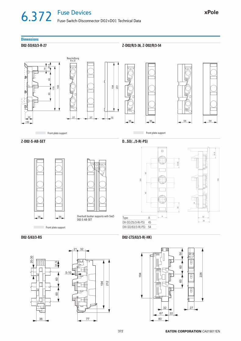
6.372
372 EATON CORPORATION CA019011EN
Fuse Devices
Fuse-Switch-Disconnector D02+D01 Technical Data
Dimensions
Z-D02/R/3-36, Z-D02/R/3-54D02-SO/63/3-R-27
Z-D02-S-AB-SET
Front plate support Front plate support
Beschriftung9 x 21
Overbuilt busbar supports with SetZ-D02-S-AB-SET
D...SO/.../3-R(-PS)
D02-S/63/3-RS D02-LTS/63/3-R(-HK)
Front plate support
Type ADII-SO/25/3-R(-PS) 45DIII-SO/63/3-R(-PS) 54

6.373
373 EATON CORPORATION CA019011EN
Fuse DevicesFuse-Links Z-DO./SE, Operating glass gG (gL)
D0
Fuse-Links Z-D0./SE, Operating class gG (gL)
Size Rated current(A)
TypeDesignation
Article No. Units perpackage
SG81111 D01 2 Z-D01/SE-2 288934 12/288D01 4 Z-D01/SE-4 288935 12/288D01 6 Z-D01/SE-6 288936 12/288D01 10 Z-D01/SE-10 288937 12/288D01 13 Z-D01/SE-13 288938 12/288D01 16 Z-D01/SE-16 288939 12/288
• In practical plastic box in the color of the visual tripping indicator - to snap on DIN rail
SG81911 D02 20 Z-D02/SE-20 288940 12/144D02 25 Z-D02/SE-25 288941 12/144D02 32 Z-D02/SE-32 288942 12/144D02 35 Z-D02/SE-35 288943 12/144D02 40 Z-D02/SE-40 288944 12/144D02 50 Z-D02/SE-50 288945 12/144D02 63 Z-D02/SE-63 288946 12/144
Description Fuse-Links Z-D0./SE, Operating class gG (gL)
• According to DIN VDE 0636, DIN 49522• For Fuse-Switch-Disconnector Z-SLS, -SLK• For Fuse-Bases D0.-SO and Z-D02/R/3
Technical DataZ-D0./SE
ElectricalOperating class gG (gL)Rated voltage
AC 400 VDC 250 V
Rated frequency 45-65 HzRated insulation voltage Ui 2500 VRated short-circuit breaking capacity
AC 50 kADC 8 kA
MechanicalSize
D01 1, 2, 4, 6, 10, 13, 16 AD02 20, 25, 32, 35, 40, 50, 63 A
Characteristics Z-D0./SETime/current characteristics of Z-D0-Fuse-Links 2 ... 63A gG(gL) Let-through characteristics of Z-D0-Fuse-Links 2 ... 63A gG(gL)
310
210
110
010
-110
-210
-310
2 41
10 2 42
10 2 43
10 2 44
10
Schm
elz
ze
ittin
s
Unbeeinflusster Strom I in AP
Nennstrom I in AN2 4 6 10 16 20 25 35 50 63
2I 2P I 2P
20
10
4
2
1
0,4
0,2
0,1
0,1 0,2 0,4 1 2 4 10 20 100
Kurzschlussstrom I in kAP
Ne
nn
str
om
Iin
AN
2
4
6
10
16
20
25
35
50
63
Durc
hla
ssstr
om
Iin
kA
D
ß
Mtgrö
tem
Gle
ihst
rom
glie
d
i
c
One
Gle
ichst
rom
glie
d
h
Möglic
he
Sto
ßku
rzsc
hlu
ssst
röm
e
Prospective current IP in A
Vir
tual
pre
-arc
ing
time
t in
s
Let-
thro
ugh
curr
ent I
D in
kA
Prospective short-circuit current IP in kA
Rat
ed c
urre
nt I n
in A
Poss
ible s
hort-
circu
t pea
k cur
rent
sWith
large
st dir
ect c
urren
t com
pone
nt
Withou
t dire
ct curr
ent co
mponen
t
Rated current IN in A
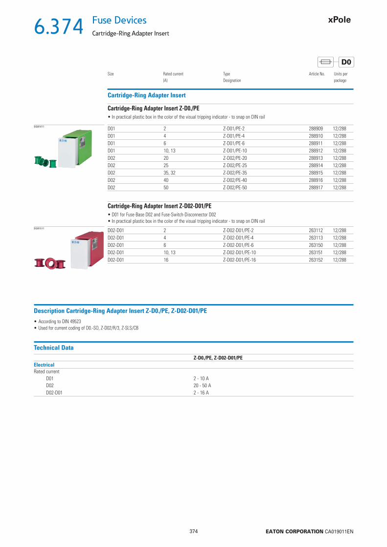
6.374
374 EATON CORPORATION CA019011EN
Fuse Devices
Cartridge-Ring Adapter Insert
D0
Cartridge-Ring Adapter Insert
Size Rated current(A)
TypeDesignation
Article No. Units perpackage
SG81611 D01 2 Z-D01/PE-2 288909 12/288D01 4 Z-D01/PE-4 288910 12/288D01 6 Z-D01/PE-6 288911 12/288D01 10, 13 Z-D01/PE-10 288912 12/288D02 20 Z-D02/PE-20 288913 12/288D02 25 Z-D02/PE-25 288914 12/288D02 35, 32 Z-D02/PE-35 288915 12/288D02 40 Z-D02/PE-40 288916 12/288D02 50 Z-D02/PE-50 288917 12/288
• In practical plastic box in the color of the visual tripping indicator - to snap on DIN rail
Cartridge-Ring Adapter Insert Z-D0./PE
SG81511 D02-D01 2 Z-D02-D01/PE-2 263112 12/288D02-D01 4 Z-D02-D01/PE-4 263113 12/288D02-D01 6 Z-D02-D01/PE-6 263150 12/288D02-D01 10, 13 Z-D02-D01/PE-10 263151 12/288D02-D01 16 Z-D02-D01/PE-16 263152 12/288
• D01 for Fuse-Base D02 and Fuse-Switch-Disconnector D02• In practical plastic box in the color of the visual tripping indicator - to snap on DIN rail
Cartridge-Ring Adapter Insert Z-D02-D01/PE
Description Cartridge-Ring Adapter Insert Z-D0./PE, Z-D02-D01/PE
• According to DIN 49523• Used for current coding of D0.-SO, Z-D02/R/3, Z-SLS/CB
Technical DataZ-D0./PE, Z-D02-D01/PE
ElectricalRated current
D01 2 - 10 AD02 20 - 50 AD02-D01 2 - 16 A

6.375
375 EATON CORPORATION CA019011EN
Fuse DevicesScrew Caps, Adapter Spring, Cartridge-Ring Adapter Insert Plier
D0
Screw Caps Z-D0./SK
Size Rated current(A)
TypeDesignation
Article No. Units perpackage
wa_sg04013 D01 max. 16 Z-D01/SK 100650 20D02 max. 63 Z-D02/SK 100651 20
Description Screw Caps Z-D0./SK
• Used for D0.-SO, Z-D02/R/3• Adapter Spring Z-D02/SIKA-HF for application of D01 fuse-links into the screw cap Z-D02/SK available
Technical DataZ-D0./SK
ElectricalRated current
D01 max. 16 AD02 max. 63 A
MechanicalElectrical thread
D01 E14D02 E18
A complete and functioning D-fuse system consists of base + fuse-link + cartridge-ring adapter insert + screw cap.The cartridge-ring adapter insert is not required for the highest rated current of each size (D01...16A and D02...63A).
Practical Hint
Adapter Spring Z-D02/SIKA-HF
Size TypeDesignation
Article No. Units perpackage
wa_sg02612 D02-D01 Z-D02/SIKA-HF 263149 50/3000
• To apply D01-Fuse-Links into the screw cap Z-D02/SK
Cartridge-ring adapter insert plier Z-D0-PE-ZSG19707 D01, D02 Z-D0-PE-Z 114324 1 / 10

6.376
376 EATON CORPORATION CA019011EN
Fuse Devices
Fuse-Links
D
Fuse-Links
Size Rated current(A)
TypeDesignation
Article No. Units perpackage
SG19007 DII E27 2 2 FUSE-D2 2A T GL/GG 500VAC E27 2D27 25/900DII E27 4 4 FUSE-D2 4A T GL/GG 500VAC E27 4D27 25/900DII E27 6 6 FUSE-D2 6A T GL/GG 500VAC E27 6D27 25/900DII E27 10 10 FUSE-D2 10A T GL/GG 500VAC E27 10D27 25/900DII E27 16 16 FUSE-D2 16A T GL/GG 500VAC E27 16D27 25/900DII E27 20 20 FUSE-D2 20A T GL/GG 500VAC E27 20D27 25/900DII E27 25 25 FUSE-D2 25A T GL/GG 500VAC E27 25D27 25/1000DIII E33 35 35 FUSE-D3 35A T GL/GG 500VAC E33 35D33 25/1000DIII E33 50 50 FUSE-D3 50A T GL/GG 500VAC E33 50D33 25/1000DIII E33 63 63 FUSE-D3 63A T GL/GG 500VAC E33 63D33 25/1000
• Rated voltage 500 V AC
Fuse-Links D27, D33 (old Z-DII./SE../GG), Operating class gG (gL)
SG19107 DII E27 6 6 FUSE 6A DII/E27 500VAC, DZ 6D27Q 25/500DII E27 10 10 FUSE 10A DII/E27 500VAC, DZ 10D27Q 25/900DII E27 16 16 FUSE 16A DII/E27 500VAC, DZ 16D27Q 25/900DII E27 20 20 FUSE 20A DII/E27 500VAC, DZ 20D27Q 25/900DII E27 25 25 FUSE 25A DII/E27 500VAC, DZ 25D27Q 25/500DIII E33 35 35 FUSE 35A DIII/E33 500VAC, DZ 35D33Q 25/1000DIII E33 50 50 FUSE 50A DIII/E33 500VAC, DZ 50D33Q 25/1000DIII E33 63 63 FUSE 63A DIII/E33 500VAC, DZ 63D33Q 25/1000
• Rated voltage 500 V AC
Fuse-Links D27, D33 (old Z-DII./SE../DZ), Operating class DZ
Description Fuse-Links Z-DII./SE
• According to DIN EN 60269-1 (VDE 0636 Part 10), DIN EN 60269-3 (VDE 0636 Part 30), DIN VDE 0636-301, CEE 16, IEC/EN 60269-1, IEC/EN 60269-3• For Fuse-Bases DII-SO..., DIII-SO...
Technical DataZ-DII./SE
ElectricalOperating class gG (gL), DZRated voltage Un
AC 500 VDC 400 V
Rated frequency 45-65 HzInsulating class C-VDE0110Rated short-circuit breaking capacity at 1.1 x Un
AC 50 kA / cos = 0.2DC 8 kA / = 15 ms
Dimensions (mm)In (A) ØA ØB
DII for Fuse-Base E272 21.5 64 21.5 66 21.5 610 21.5 816 21.5 1020 21.5 1225 21.5 14
DIII for Fuse-Base E3335 27 1650 27 1863 27 20

6.377
377 EATON CORPORATION CA019011EN
Fuse DevicesFuse-Links
D
Characteristics Z-DII./SE
Time/current characteristics of Z-DII-Fuse-Links 2 ... 63A gG(gL) Let-through characteristics of Z-DII-Fuse-Links 2 ... 63A gG(gL)
Prospective current Ip in A
Pre-
arci
ng ti
me
t in
s
Max
imum
val
ue o
f cur
rent
I D in
kA
Rat
ed c
urre
nt I n
in A
Prospective current Ip in A
Characteristics Z-DII./SE
Melting energy characteristics I2t/A of Z-DII-Fuse-Links 2 ... 63A gG(gL) Time/current characteristics of Z-DII-Fuse-Links 2 ... 63A DZ
Prospective current Ip in A
I2A
val
ue in
A2 (
s)
Pre-
arci
ng ti
me
t in
s
Prospective current Ip in A
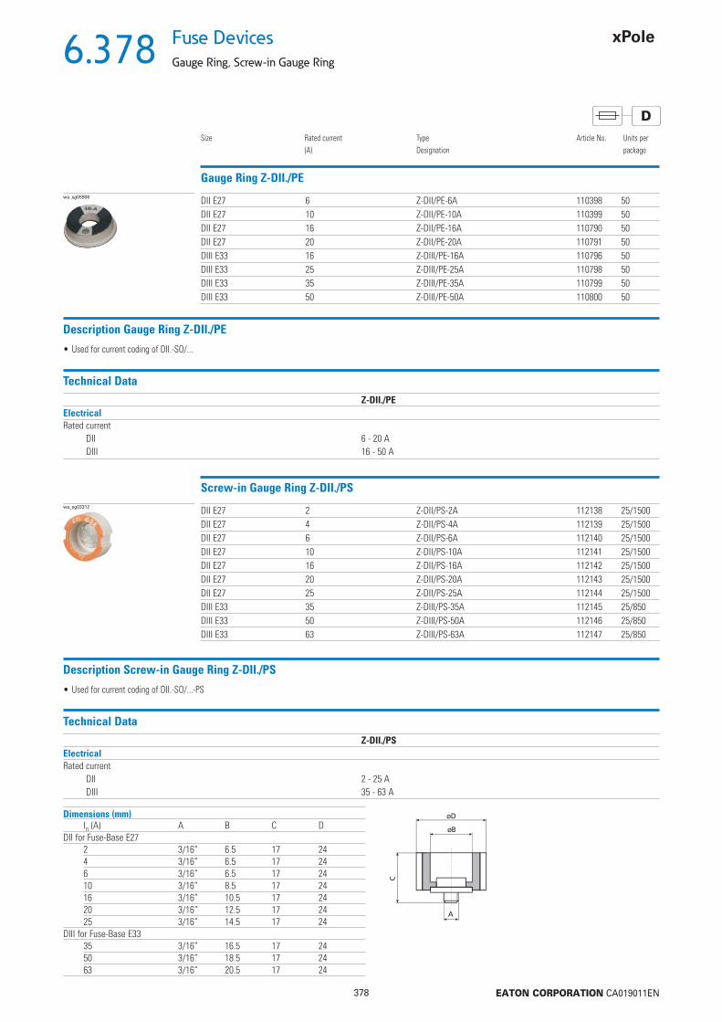
6.378
378 EATON CORPORATION CA019011EN
Fuse Devices
Gauge Ring, Screw-in Gauge Ring
D
Gauge Ring Z-DII./PE
Size Rated current(A)
TypeDesignation
Article No. Units perpackage
wa_sg05908 DII E27 6 Z-DII/PE-6A 110398 50DII E27 10 Z-DII/PE-10A 110399 50DII E27 16 Z-DII/PE-16A 110790 50DII E27 20 Z-DII/PE-20A 110791 50DIII E33 16 Z-DIII/PE-16A 110796 50DIII E33 25 Z-DIII/PE-25A 110798 50DIII E33 35 Z-DIII/PE-35A 110799 50DIII E33 50 Z-DIII/PE-50A 110800 50
Description Gauge Ring Z-DII./PE
• Used for current coding of DII.-SO/...
Technical DataZ-DII./PE
ElectricalRated current
DII 6 - 20 ADIII 16 - 50 A
Screw-in Gauge Ring Z-DII./PSwa_sg03312 DII E27 2 Z-DII/PS-2A 112138 25/1500
DII E27 4 Z-DII/PS-4A 112139 25/1500DII E27 6 Z-DII/PS-6A 112140 25/1500DII E27 10 Z-DII/PS-10A 112141 25/1500DII E27 16 Z-DII/PS-16A 112142 25/1500DII E27 20 Z-DII/PS-20A 112143 25/1500DII E27 25 Z-DII/PS-25A 112144 25/1500DIII E33 35 Z-DIII/PS-35A 112145 25/850DIII E33 50 Z-DIII/PS-50A 112146 25/850DIII E33 63 Z-DIII/PS-63A 112147 25/850
Description Screw-in Gauge Ring Z-DII./PS
• Used for current coding of DII.-SO/...-PS
Technical DataZ-DII./PS
ElectricalRated current
DII 2 - 25 ADIII 35 - 63 A
Dimensions (mm)In (A) A B C D
DII for Fuse-Base E272 3/16” 6.5 17 244 3/16” 6.5 17 246 3/16” 6.5 17 2410 3/16” 8.5 17 2416 3/16” 10.5 17 2420 3/16” 12.5 17 2425 3/16” 14.5 17 24
DIII for Fuse-Base E3335 3/16” 16.5 17 2450 3/16” 18.5 17 2463 3/16” 20.5 17 24
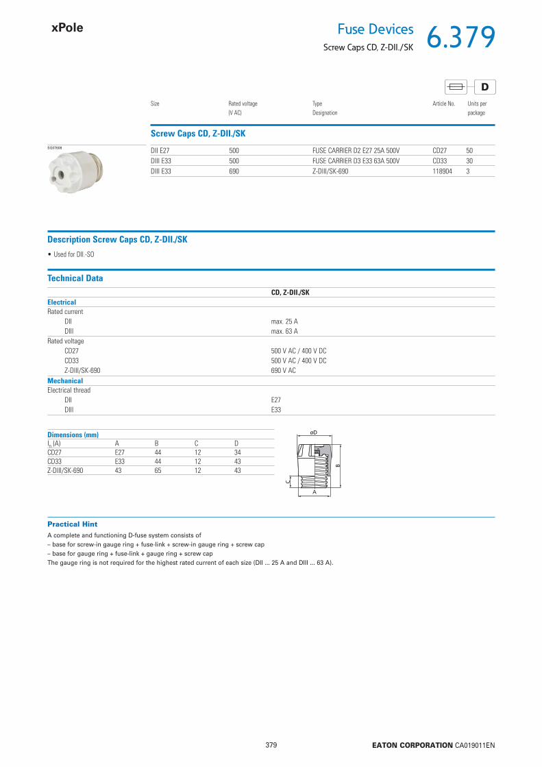
6.379
379 EATON CORPORATION CA019011EN
Fuse DevicesScrew Caps CD, Z-DII./SK
D
Screw Caps CD, Z-DII./SK
Size Rated voltage(V AC)
TypeDesignation
Article No. Units perpackage
SG07608 DII E27 500 FUSE CARRIER D2 E27 25A 500V CD27 50DIII E33 500 FUSE CARRIER D3 E33 63A 500V CD33 30DIII E33 690 Z-DIII/SK-690 118904 3
Description Screw Caps CD, Z-DII./SK
• Used for DII.-SO
Technical DataCD, Z-DII./SK
ElectricalRated current
DII max. 25 ADIII max. 63 A
Rated voltageCD27 500 V AC / 400 V DCCD33 500 V AC / 400 V DCZ-DIII/SK-690 690 V AC
MechanicalElectrical thread
DII E27DIII E33
Dimensions (mm)In (A) A B C DCD27 E27 44 12 34CD33 E33 44 12 43Z-DIII/SK-690 43 65 12 43
A complete and functioning D-fuse system consists of – base for screw-in gauge ring + fuse-link + screw-in gauge ring + screw cap– base for gauge ring + fuse-link + gauge ring + screw capThe gauge ring is not required for the highest rated current of each size (DII ... 25 A and DIII ... 63 A).
Practical Hint
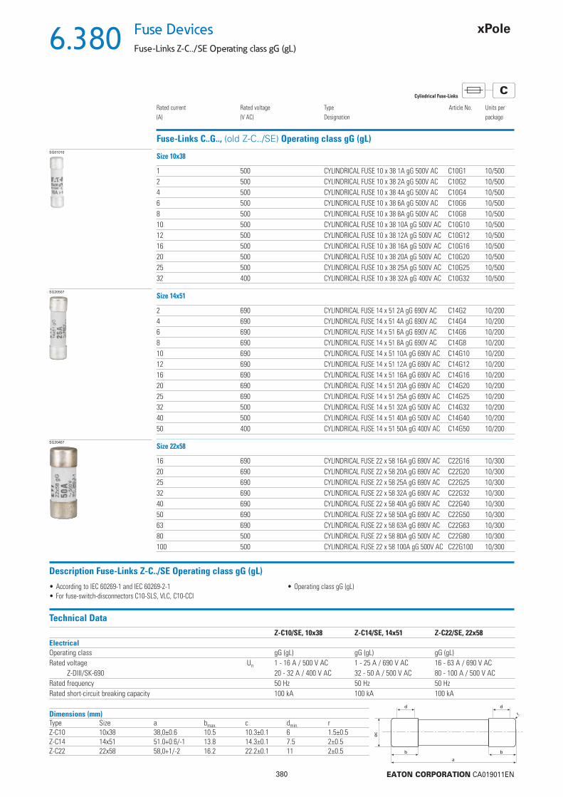
6.380
380 EATON CORPORATION CA019011EN
Fuse Devices
Fuse-Links Z-C../SE Operating class gG (gL)
CCylindrical Fuse-Links
Fuse-Links C..G.., (old Z-C../SE) Operating class gG (gL)
Rated current(A)
Rated voltage(V AC)
TypeDesignation
Article No. Units perpackage
SG01010
1 500 CYLINDRICAL FUSE 10 x 38 1A gG 500V AC C10G1 10/5002 500 CYLINDRICAL FUSE 10 x 38 2A gG 500V AC C10G2 10/5004 500 CYLINDRICAL FUSE 10 x 38 4A gG 500V AC C10G4 10/5006 500 CYLINDRICAL FUSE 10 x 38 6A gG 500V AC C10G6 10/5008 500 CYLINDRICAL FUSE 10 x 38 8A gG 500V AC C10G8 10/50010 500 CYLINDRICAL FUSE 10 x 38 10A gG 500V AC C10G10 10/50012 500 CYLINDRICAL FUSE 10 x 38 12A gG 500V AC C10G12 10/50016 500 CYLINDRICAL FUSE 10 x 38 16A gG 500V AC C10G16 10/50020 500 CYLINDRICAL FUSE 10 x 38 20A gG 500V AC C10G20 10/50025 500 CYLINDRICAL FUSE 10 x 38 25A gG 500V AC C10G25 10/50032 400 CYLINDRICAL FUSE 10 x 38 32A gG 400V AC C10G32 10/500
Size 10x38
SG20507
2 690 CYLINDRICAL FUSE 14 x 51 2A gG 690V AC C14G2 10/2004 690 CYLINDRICAL FUSE 14 x 51 4A gG 690V AC C14G4 10/2006 690 CYLINDRICAL FUSE 14 x 51 6A gG 690V AC C14G6 10/2008 690 CYLINDRICAL FUSE 14 x 51 8A gG 690V AC C14G8 10/20010 690 CYLINDRICAL FUSE 14 x 51 10A gG 690V AC C14G10 10/20012 690 CYLINDRICAL FUSE 14 x 51 12A gG 690V AC C14G12 10/20016 690 CYLINDRICAL FUSE 14 x 51 16A gG 690V AC C14G16 10/20020 690 CYLINDRICAL FUSE 14 x 51 20A gG 690V AC C14G20 10/20025 690 CYLINDRICAL FUSE 14 x 51 25A gG 690V AC C14G25 10/20032 500 CYLINDRICAL FUSE 14 x 51 32A gG 500V AC C14G32 10/20040 500 CYLINDRICAL FUSE 14 x 51 40A gG 500V AC C14G40 10/20050 400 CYLINDRICAL FUSE 14 x 51 50A gG 400V AC C14G50 10/200
Size 14x51
SG20407
16 690 CYLINDRICAL FUSE 22 x 58 16A gG 690V AC C22G16 10/30020 690 CYLINDRICAL FUSE 22 x 58 20A gG 690V AC C22G20 10/30025 690 CYLINDRICAL FUSE 22 x 58 25A gG 690V AC C22G25 10/30032 690 CYLINDRICAL FUSE 22 x 58 32A gG 690V AC C22G32 10/30040 690 CYLINDRICAL FUSE 22 x 58 40A gG 690V AC C22G40 10/30050 690 CYLINDRICAL FUSE 22 x 58 50A gG 690V AC C22G50 10/30063 690 CYLINDRICAL FUSE 22 x 58 63A gG 690V AC C22G63 10/30080 500 CYLINDRICAL FUSE 22 x 58 80A gG 500V AC C22G80 10/300100 500 CYLINDRICAL FUSE 22 x 58 100A gG 500V AC C22G100 10/300
Size 22x58
Description Fuse-Links Z-C../SE Operating class gG (gL)
• According to IEC 60269-1 and IEC 60269-2-1• For fuse-switch-disconnectors C10-SLS, VLC, C10-CCI
• Operating class gG (gL)
Technical DataZ-C10/SE, 10x38 Z-C14/SE, 14x51 Z-C22/SE, 22x58
ElectricalOperating class gG (gL) gG (gL) gG (gL)Rated voltage Un 1 - 16 A / 500 V AC 1 - 25 A / 690 V AC 16 - 63 A / 690 V AC
Z-DIII/SK-690 20 - 32 A / 400 V AC 32 - 50 A / 500 V AC 80 - 100 A / 500 V ACRated frequency 50 Hz 50 Hz 50 HzRated short-circuit breaking capacity 100 kA 100 kA 100 kA
Dimensions (mm)Type Size a bmax. c dmin. rZ-C10 10x38 38,0±0.6 10.5 10.3±0.1 6 1.5±0.5Z-C14 14x51 51.0+0.6/-1 13.8 14.3±0.1 7.5 2±0.5Z-C22 22x58 58,0+1/-2 16.2 22.2±0.1 11 2±0.5
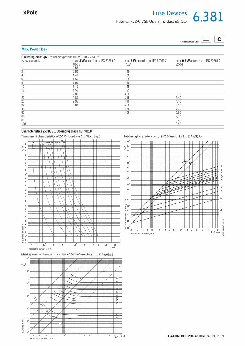
6.381
381 EATON CORPORATION CA019011EN
Fuse DevicesFuse-Links Z-C../SE Operating class gG (gL)
CCylindrical Fuse-Links
Max. Power loss
Operating class gG - Power dissipations 400 V / 500 V / 690 VRated current In max. 3 W according to IEC 60269-2
10x38max. 5 W according to IEC 60269-214x51
max. 9.5 W according to IEC 60269-222x58
1 0.552 0.90 1.454 1.45 1.606 1.55 1.958 1.05 1.4010 1.10 1.4512 1.55 1.9516 2.85 3.00 3.0520 2.80 3.15 3.4025 2.95 4.10 4.4032 3.00 4.80 5.1040 4.75 7.2050 4.95 7.6063 8,0080 8.20100 9.40
Characteristics Z-C10/SE, Operating class gG, 10x38Time/current characteristics of Z-C10-Fuse-Links 2 ... 32A gG(gL) Let-through characteristics of Z-C10-Fuse-Links 2 ... 32A gG(gL)
Prospective current Ip in A
Pre-
arci
ng ti
me
t in
s
Max
imum
val
ue o
f cur
rent
I D in
kA
Rat
ed c
urre
nt I n
in A
Prospective current Ip in A
Melting energy characteristics I2t/A of Z-C10-Fuse-Links 1 ... 32A gG(gL)
Prospective current Ip in A
I2A
val
ue in
A2 (
s)
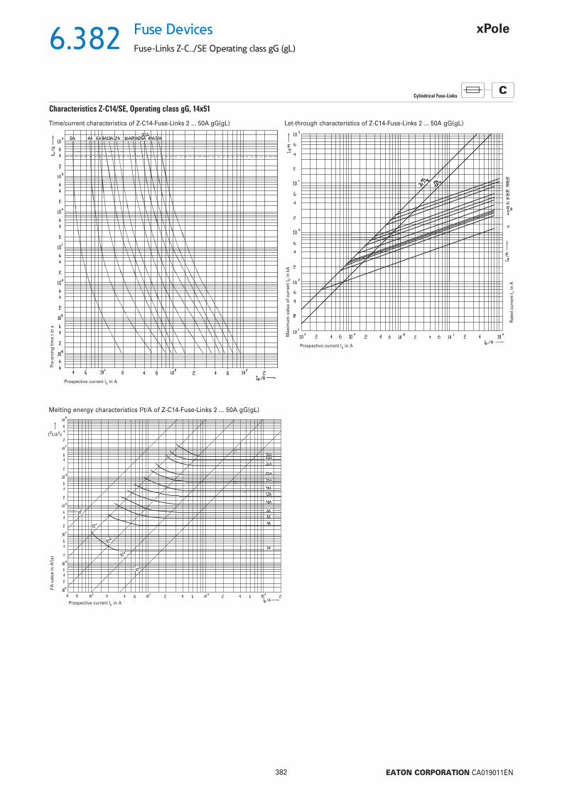
6.382
382 EATON CORPORATION CA019011EN
Fuse Devices
Fuse-Links Z-C../SE Operating class gG (gL)
CCylindrical Fuse-Links
Characteristics Z-C14/SE, Operating class gG, 14x51
Time/current characteristics of Z-C14-Fuse-Links 2 ... 50A gG(gL) Let-through characteristics of Z-C14-Fuse-Links 2 ... 50A gG(gL)
Prospective current Ip in A
Pre-
arci
ng ti
me
t in
s
Max
imum
val
ue o
f cur
rent
I D in
kA
Rat
ed c
urre
nt I n
in A
Prospective current Ip in A
Melting energy characteristics I2t/A of Z-C14-Fuse-Links 2 ... 50A gG(gL)
Prospective current Ip in A
I2A
val
ue in
A2 (
s)

6.383
383 EATON CORPORATION CA019011EN
Fuse DevicesFuse-Links Z-C../SE Operating class gG (gL)
CCylindrical Fuse-Links
Characteristics Z-C22/SE, Operating class gG, 22x58
Time/current characteristics of Z-C22-Fuse-Links 16 ... 100A gG(gL) Let-through characteristics of Z-C22-Fuse-Links 16 ... 100A gG(gL)
Prospective current Ip in A
Pre-
arci
ng ti
me
t in
s
Max
imum
val
ue o
f cur
rent
I D in
kA
Rat
ed c
urre
nt I n
in A
Prospective current Ip in A
Melting energy characteristics I2t/A of Z-C22-Fuse-Links 16 ... 100A gG(gL)
Prospective current Ip in A
I2A
val
ue in
A2 (
s)

6.384
384 EATON CORPORATION CA019011EN
Fuse Devices
Fuse-Links PV-..A10F Photovoltaic Application
Cylindrical Fuse-LinksC
Fuse-Links PV-..A10F (old ASFLC10-..A-gPV-SOL) Photovoltaic Application
Rated current(A)
Rated voltage(V DC)
TypeDesignation
Article No. Units perpackage
SG11008
2 1000 2AMP 1000V DC SOLAR FERRULE 10 X 38MM PV-2A10F 10/5004 1000 4AMP 1000V DC SOLAR FERRULE 10 X 38MM PV-4A10F 10/5006 1000 6AMP 1000V DC SOLAR FERRULE 10 X 38MM PV-6A10F 10/5008 1000 8AMP 1000V DC SOLAR FERRULE 10 X 38MM PV-8A10F 10/50010 1000 10AMP 1000V DC SOLAR FERRULE 10 X 38MM PV-10A10F 10/50012 1000 12AMP 1000V DC SOLAR FERRULE 10 X 38MM PV-12A10F 10/50015 1000 15AMP 1000V DC SOLAR FERRULE 10 X 38MM PV-15A10F 10/50020 1000 20AMP 1000V DC SOLAR FERRULE 10 X 38MM PV-20A10F 10/500*) melamine instead of ceramic
Size 10x38
PV-fuse-link selection: Maximum DC Operating voltage of the fuse-link must be:
1.2 x Voc of string Rated current In of the fuse-link must be higher or equal than:
1.5 x IscIsc . . . . . . short circuit current of PV-moduleVoc . . . . . open circuit voltage of string
Description Fuse-Links ASFLC10-..A-gPV-SOL Photovoltaic Application
• According to IEC 60269-1 and IEC 60269-4• For fuse-switch-disconnectors FCFDC10DI
Technical DataASFLC10-..A-gPV-SOL, 10x38
ElectricalRated voltage Un 6 - 20 A / 1000 V DC
25 A / 900 V DCRated frequency –Rated short-circuit breaking capacity 30 kA = L/R 2 ms
Dimensions (mm)Type Size a bmax. c dmin. rASFLC10 10x38 38,0±0.6 10.5 10.3±0.1 6 1.5±0.5
Max.Power lossRated currentIn
[A]
Pre-arcing Joule integralL/R = 2 ms
[A2s]
Operating Joule integralL/R = 2 ms
[A2s]
Power lossat 0.7 x In
[W]
Power lossat InPd[W]
Weight
[g]
2 1.3 3.5 1.47 1.00 104 3.3 28 0.52 1.25 106 5.5 45 0.73 1.65 108 8 62 0.93 1.9 1010 11 88 1.06 2.3 1012 23 180 1.03 1.9 1016 35 270 1.00 2.5 1020 50 430 1.18 3.25 1025 75 620 1.25 3.45 10

6.385
385 EATON CORPORATION CA019011EN
Fuse DevicesFuse-Links ASFLC10-..A-gPV-SOL Photovoltaic Application
Cylindrical Fuse-LinksC
Characteristics ASFLC10-..A-gPV-SOL, Photovoltaic Application
Time/current characteristics of ASFLC10-..A-gPV-SOL Fuse-Links 2 ... 25A
Prospective current Ip in A
Pre-
arci
ng ti
me
t in
s

6.386
386 EATON CORPORATION CA019011EN
Fuse Devices
Solid-Links Z-NH-../TR
NH
Solid-Links Z-NH-../TR
Size TypeDesignation
Article No. Units perpackage
wa_sg04413 00 Z-NH-00/TR 263114 3 / 1801 Z-NH-1/TR 263115 6 / 602 Z-NH-2/TR 263116 6 / 603 Z-NH-3/TR 263117 3 / 30
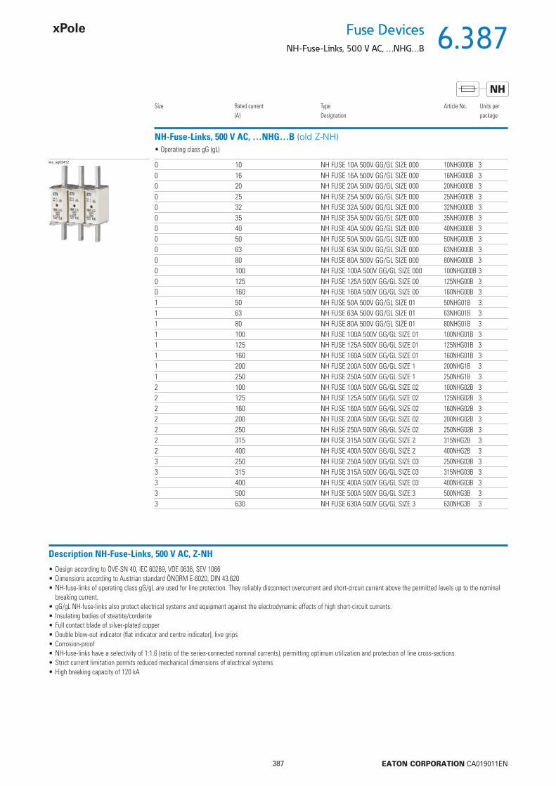
6.387
387 EATON CORPORATION CA019011EN
Fuse DevicesNH-Fuse-Links, 500 V AC, …NHG…B
NH
NH-Fuse-Links, 500 V AC, …NHG…B (old Z-NH)
Size Rated current(A)
TypeDesignation
Article No. Units perpackage
wa_sg03412 0 10 NH FUSE 10A 500V GG/GL SIZE 000 10NHG000B 30 16 NH FUSE 16A 500V GG/GL SIZE 000 16NHG000B 30 20 NH FUSE 20A 500V GG/GL SIZE 000 20NHG000B 30 25 NH FUSE 25A 500V GG/GL SIZE 000 25NHG000B 30 32 NH FUSE 32A 500V GG/GL SIZE 000 32NHG000B 30 35 NH FUSE 35A 500V GG/GL SIZE 000 35NHG000B 30 40 NH FUSE 40A 500V GG/GL SIZE 000 40NHG000B 30 50 NH FUSE 50A 500V GG/GL SIZE 000 50NHG000B 30 63 NH FUSE 63A 500V GG/GL SIZE 000 63NHG000B 30 80 NH FUSE 80A 500V GG/GL SIZE 000 80NHG000B 30 100 NH FUSE 100A 500V GG/GL SIZE 000 100NHG000B 30 125 NH FUSE 125A 500V GG/GL SIZE 00 125NHG00B 30 160 NH FUSE 160A 500V GG/GL SIZE 00 160NHG00B 31 50 NH FUSE 50A 500V GG/GL SIZE 01 50NHG01B 31 63 NH FUSE 63A 500V GG/GL SIZE 01 63NHG01B 31 80 NH FUSE 80A 500V GG/GL SIZE 01 80NHG01B 31 100 NH FUSE 100A 500V GG/GL SIZE 01 100NHG01B 31 125 NH FUSE 125A 500V GG/GL SIZE 01 125NHG01B 31 160 NH FUSE 160A 500V GG/GL SIZE 01 160NHG01B 31 200 NH FUSE 200A 500V GG/GL SIZE 1 200NHG1B 31 250 NH FUSE 250A 500V GG/GL SIZE 1 250NHG1B 32 100 NH FUSE 100A 500V GG/GL SIZE 02 100NHG02B 32 125 NH FUSE 125A 500V GG/GL SIZE 02 125NHG02B 32 160 NH FUSE 160A 500V GG/GL SIZE 02 160NHG02B 32 200 NH FUSE 200A 500V GG/GL SIZE 02 200NHG02B 32 250 NH FUSE 250A 500V GG/GL SIZE 02 250NHG02B 32 315 NH FUSE 315A 500V GG/GL SIZE 2 315NHG2B 32 400 NH FUSE 400A 500V GG/GL SIZE 2 400NHG2B 33 250 NH FUSE 250A 500V GG/GL SIZE 03 250NHG03B 33 315 NH FUSE 315A 500V GG/GL SIZE 03 315NHG03B 33 400 NH FUSE 400A 500V GG/GL SIZE 03 400NHG03B 33 500 NH FUSE 500A 500V GG/GL SIZE 3 500NHG3B 33 630 NH FUSE 630A 500V GG/GL SIZE 3 630NHG3B 3
• Operating class gG (gL)
Description NH-Fuse-Links, 500 V AC, Z-NH
• Design according to ÖVE-SN 40, IEC 60269, VDE 0636, SEV 1066• Dimensions according to Austrian standard ÖNORM E-6020, DIN 43.620• NH-fuse-links of operating class gG/gL are used for line protection. They reliably disconnect overcurrent and short-circuit current above the permitted levels up to the nominal
breaking current. • gG/gL NH-fuse-links also protect electrical systems and equipment against the electrodynamic effects of high short-circuit currents.• Insulating bodies of steatite/corderite • Full contact blade of silver-plated copper• Double blow-out indicator (fl at indicator and centre indicator), live grips• Corrosion-proof• NH-fuse-links have a selectivity of 1:1.6 (ratio of the series-connected nominal currents), permitting optimum utilization and protection of line cross-sections.• Strict current limitation permits reduced mechanical dimensions of electrical systems• High breaking capacity of 120 kA

6.388
388 EATON CORPORATION CA019011EN
Fuse Devices
NH-Fuse-Links, 500 V AC, …NHG…B
NH
Technical DataNH Fuse-00/ NH Fuse-1/ NH Fuse-2/ NH Fuse-3/
ElectricalRated voltage
AC 500 V 500 V 500 V 500 VDC 230 V 440 V 440 V 440 V
Nominal current 10-160 A 50-250 A 100-400 A 250-630 ARated frequency 45-62 Hz 45-62 Hz 45-62 Hz 45-62 HzNominal breaking capacity
AC 120 kA 120 kA 120 kA 120 kADC 25 kA 25 kA 25 kA 25 kA
Nominal breaking capacityIn = 10 A 1.1 W - - -16 A 1.6 W - - -20 A 1.7 W - - -25 A 1.9 W - - -35 A 3.0 W - - -40 A 3.5 W - - -50 A 4.6 W 5.4 W - -63 A 5.4 W 6.3 W - -80 A 5.1 W 7.2 W - -100 A 6.9 W 8.6 W 8.8 W -125 A 10.3 W 11.9 W 12.1 W -160 A 11.0 W 13.9 W 14.0 W -200 A - 15.2 W 15.2 W -250 A - 21.8 W 21.8 W 19.4 W315 A - - 23.7 W 23.7 W400 A - - 30.5 W 30.5 W500 A - - - 42.0 W630 A - - - 47,0 W
Dimensions (mm)Type Size A B C D E F G H KZ-NH-00/ up to 100 A 000 79 53 47 35 15 21 52 7.5 6
125 - 160 A 00 79 53 47 35 15 28 56 12 6Z-NH-1/ up to 160 A 1C 135 68 65 40 15 28 61 12 6
200 - 250 A 1 135 72 65 40 20 46 65 14 6Z-NH-2/ up to 250 A 2C 150 72 65 48 20 46 73 14 6
315 - 400 A 2 150 72 65 48 26 54 73 14 6Z-NH-3/ up to 400 A 3C 150 72 65 60 26 54 84 14 6
500 - 630 A 3 150 72 65 60 33 65 84 14 6
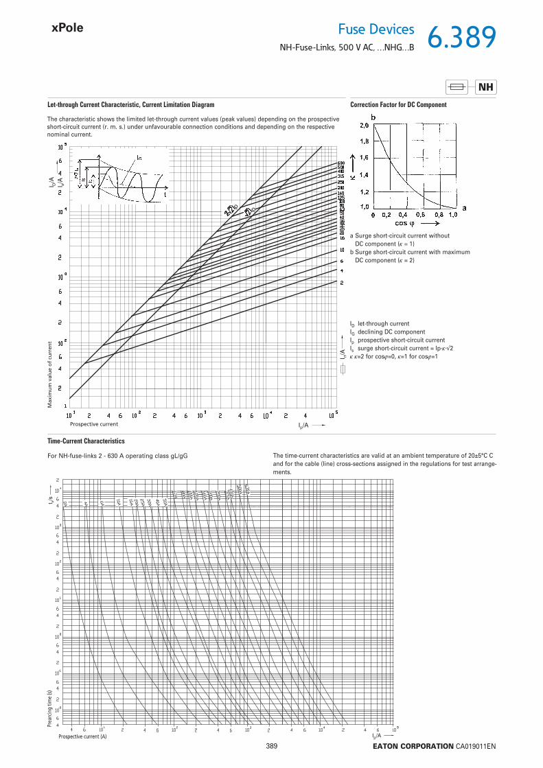
6.389
389 EATON CORPORATION CA019011EN
Fuse DevicesNH-Fuse-Links, 500 V AC, …NHG…B
NH
Let-through Current Characteristic, Current Limitation Diagram Correction Factor for DC Component
Time-Current Characteristics
The characteristic shows the limited let-through current values (peak values) depending on the prospective short-circuit current (r. m. s.) under unfavourable connection conditions and depending on the respective nominal current.
ID let-through currentIG declining DC componentIp prospective short-circuit currentIs surge short-circuit current = Ip··2=2 for cos=0, =1 for cos=1
a Surge short-circuit current without DC component ( = 1)
b Surge short-circuit current with maximum DC component ( = 2)
The time-current characteristics are valid at an ambient temperature of 20±5°C C and for the cable (line) cross-sections assigned in the regulations for test arrange-ments.
For NH-fuse-links 2 - 630 A operating class gL/gG

6.390
390 EATON CORPORATION CA019011EN
Fuse Devices
Fuse Switch Disconnectors XNH...
• For fuse links NH000 to NH3
• Rated operating current of 160, 250, 400 and
630 A
• Sizes 00, 1, 2 and 3
• Degree of protection IP2XC
• Frame widths of 106, 184, 210 and 250 mm
• For mounting plate, DIN rail and busbar sys-
tem of 60 mm
• System size 195 and 300 mm
• Can be locked with a pad lock
• Current-theft protection
• Flex-System for cable connection at the top/
bottom
• Improved operator safety
• Flat connection for cable lug, box terminal,
clamp-type terminal,
prism terminal and double prism terminal
• Switch cover with safety parking position
• Fuse monitoring light with LED on the device
• Electronic fuse monitoring
• SmartWire-DT® option
Description
vt61615 vt64215
vt64015 vt61715

6.391
391 EATON CORPORATION CA019011EN
Fuse DevicesFuse Switch Disconnectors XNH...
System Overview 3-pole
System Overview Accessories
Setup options
Standard connection options
SmartWire-DT® Module
XNH00 XNH1 XNH2 XNH3Basic device
Fuse control - light
Fuse control - electronic
XNH00 XNH1 XNH2 XNH3Busbar system 60 mm
Mounting plate
DIN rails - -
XNH00 XNH1 XNH2 XNH3Flat connection
Installation distribution board box terminal BT2 1) - - -Box terminal
XNH00 XNH1 XNH2 XNH3Complete set for direct mounting on the switchgear (with 2 DX)
For fi xing on the mounting plate (with 2 DX)
XNH00 XNH1 XNH2 XNH3DIN rail fastening - -Locking device
Current-theft protection
Switch position indicator
Mechanical fuse monitoring
Internal lock for contact protection
Clamp-type terminal
Prism terminal
Double-prism terminal -
Box terminal -
Extinguishing chambers -
Spare handle cover
Connection kit, 2- and 4-pole -
Cover supports
Reach-over protection at busbar
Cover for connection area
Extension of the cover for the connection area - - -Height compensation adapter - - -
1) Deeper-positioned box terminal with busbar-devices for improved connection when using front panels, e.g. installation distribution boards.

6.392
392 EATON CORPORATION CA019011EN
Fuse Devices
Fuse Switch Disconnectors XNH...
Fuse Switch Disconnector XNH… for Mounting Plate
Size Type of connection Ie (A) Typedesignation
Article No. Pack(pcs.)
• Degree of protection IP2XC in operating mode• According to IEC/EN 60947-3• AC 690 V / DC 440 V• Conditional rated short-circuit current 120 kA (500 V) and 100 kA (690 V)• Reaction to fi re according to UL 94, self-extinguishing• Current paths of electrolytic copper, silver-plated• For fi xing on mounting plates and DIN rails• Fuse Control Light with optical signalling of triggered fuse-links• Fuse Control FCE with electronic monitoring of fuse-links
Basic Device
vt61615 00 Flat connection M8 max. 95 mm2 160 XNH00-A160 183025 1Box terminal 1,5 - 95 mm2 160 XNH00-A160-BT 183026 1
1 Flat connection M10 max. 150 mm2 250 XNH1-A250 183043 1Box terminal 35 - 150 mm2 250 XNH1-A250-BT 183044 1
2 Flat connection M10 max. 240 mm2 400 XNH2-A400 183057 1Box terminal 95 - 300 mm2 400 XNH2-A400-BT 183058 1
3 Flat connection M10 max. 300 mm2 630 XNH3-A630 183071 1Box terminal 95 - 300 mm2 630 XNH3-A630-BT 183072 1
3-pole for mounting plate
vt64015
Fuse Control - light
wa_vt15515 00 Flat connection M8 max. 95 mm2 160 XNH00-FCL-A160 183027 1Box terminal 1,5 - 95 mm2 160 XNH00-FCL-A160-BT 183028 1
1 Flat connection M10 max. 150 mm2 250 XNH1-FCL-A250 183045 1Box terminal 35 - 150 mm2 250 XNH1-FCL-A250-BT 183046 1
2 Flat connection M10 max. 240 mm2 400 XNH2-FCL-A400 183059 1Box terminal 95 - 300 mm2 400 XNH2-FCL-A400-BT 183060 1
3 Flat connection M10 max. 300 mm2 630 XNH3-FCL-A630 183073 1Box terminal 95 - 300 mm2 630 XNH3-FCL-A630-BT 183074 1
3-pole for mounting plate
Fuse Control FCE
vt02416 00 Flat connection M8 max. 95 mm2 160 XNH00-FCE-A160 183029 1Box terminal 1,5 - 95 mm2 160 XNH00-FCE-A160-BT 183030 1
1 Flat connection M10 max. 150 mm2 250 XNH1-FCE-A250 183047 1Box terminal 35 - 150 mm2 250 XNH1-FCE-A250-BT 183048 1
2 Flat connection M10 max. 240 mm2 400 XNH2-FCE-A400 183061 1Box terminal 95 - 300 mm2 400 XNH2-FCE-A400-BT 183062 1
3 Flat connection M10 max. 300 mm2 630 XNH3-FCE-A630 183075 1Box terminal 95 - 300 mm2 630 XNH3-FCE-A630-BT 183076 1
3-pole for mounting plate
vt00217 00 Flat connection M8 max. 95 mm² 160 XNH00-1-A160 183031 1Box terminal 1,5 - 95 mm² 160 XNH00-1-A160-BT 183032 1
1 Flat connection M10 max. 150 mm² 250 XNH1-1-A250 183049 1Box terminal 35 - 150 mm² 250 XNH1-1-A250-BT 183050 1
3 Flat connection M10 max. 300 mm² 400/630 XNH32-1-A630 183063 1Box terminal 95 - 300 mm² 400/630 XNH32-1-A630-BT 183064 1
1-pole for mounting plate
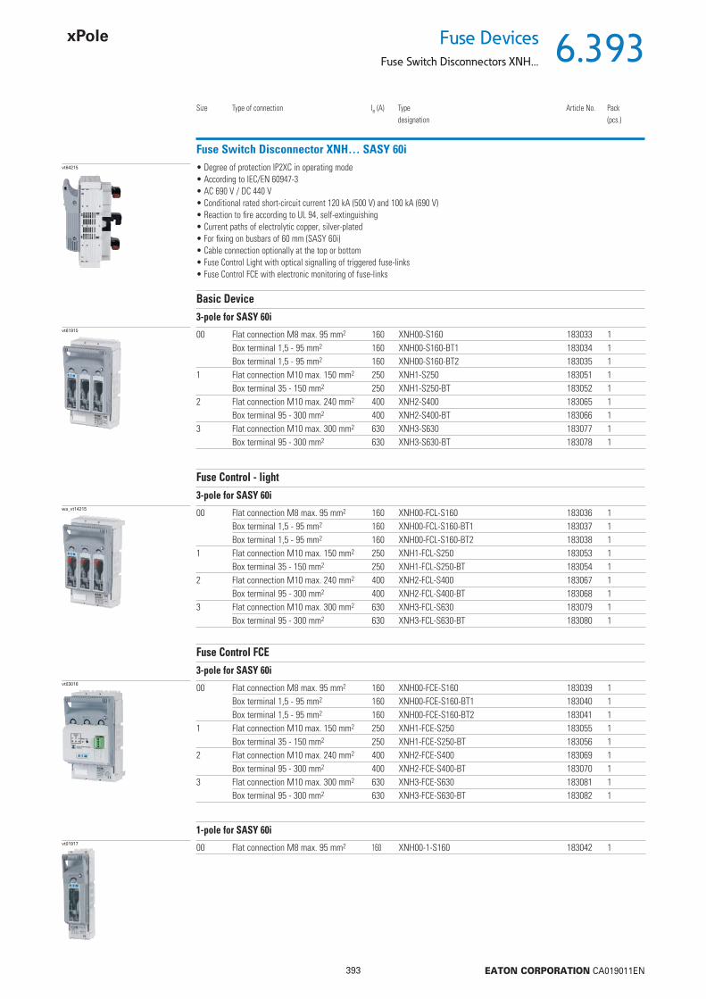
6.393
393 EATON CORPORATION CA019011EN
Fuse DevicesFuse Switch Disconnectors XNH...
Fuse Switch Disconnector XNH… SASY 60i
Size Type of connection Ie (A) Typedesignation
Article No. Pack(pcs.)
• Degree of protection IP2XC in operating mode• According to IEC/EN 60947-3• AC 690 V / DC 440 V• Conditional rated short-circuit current 120 kA (500 V) and 100 kA (690 V)• Reaction to fi re according to UL 94, self-extinguishing• Current paths of electrolytic copper, silver-plated• For fi xing on busbars of 60 mm (SASY 60i)• Cable connection optionally at the top or bottom• Fuse Control Light with optical signalling of triggered fuse-links• Fuse Control FCE with electronic monitoring of fuse-links
Basic Device
vt61915 00 Flat connection M8 max. 95 mm2 160 XNH00-S160 183033 1Box terminal 1,5 - 95 mm2 160 XNH00-S160-BT1 183034 1Box terminal 1,5 - 95 mm2 160 XNH00-S160-BT2 183035 1
1 Flat connection M10 max. 150 mm2 250 XNH1-S250 183051 1Box terminal 35 - 150 mm2 250 XNH1-S250-BT 183052 1
2 Flat connection M10 max. 240 mm2 400 XNH2-S400 183065 1Box terminal 95 - 300 mm2 400 XNH2-S400-BT 183066 1
3 Flat connection M10 max. 300 mm2 630 XNH3-S630 183077 1Box terminal 95 - 300 mm2 630 XNH3-S630-BT 183078 1
3-pole for SASY 60i
vt64215
Fuse Control - light
wa_vt14215 00 Flat connection M8 max. 95 mm2 160 XNH00-FCL-S160 183036 1Box terminal 1,5 - 95 mm2 160 XNH00-FCL-S160-BT1 183037 1Box terminal 1,5 - 95 mm2 160 XNH00-FCL-S160-BT2 183038 1
1 Flat connection M10 max. 150 mm2 250 XNH1-FCL-S250 183053 1Box terminal 35 - 150 mm2 250 XNH1-FCL-S250-BT 183054 1
2 Flat connection M10 max. 240 mm2 400 XNH2-FCL-S400 183067 1Box terminal 95 - 300 mm2 400 XNH2-FCL-S400-BT 183068 1
3 Flat connection M10 max. 300 mm2 630 XNH3-FCL-S630 183079 1Box terminal 95 - 300 mm2 630 XNH3-FCL-S630-BT 183080 1
3-pole for SASY 60i
Fuse Control FCE
vt03016 00 Flat connection M8 max. 95 mm2 160 XNH00-FCE-S160 183039 1Box terminal 1,5 - 95 mm2 160 XNH00-FCE-S160-BT1 183040 1Box terminal 1,5 - 95 mm2 160 XNH00-FCE-S160-BT2 183041 1
1 Flat connection M10 max. 150 mm2 250 XNH1-FCE-S250 183055 1Box terminal 35 - 150 mm2 250 XNH1-FCE-S250-BT 183056 1
2 Flat connection M10 max. 240 mm2 400 XNH2-FCE-S400 183069 1Box terminal 95 - 300 mm2 400 XNH2-FCE-S400-BT 183070 1
3 Flat connection M10 max. 300 mm2 630 XNH3-FCE-S630 183081 1Box terminal 95 - 300 mm2 630 XNH3-FCE-S630-BT 183082 1
3-pole for SASY 60i
vt01917 00 Flat connection M8 max. 95 mm2 160 XNH00-1-S160 183042 1
1-pole for SASY 60i
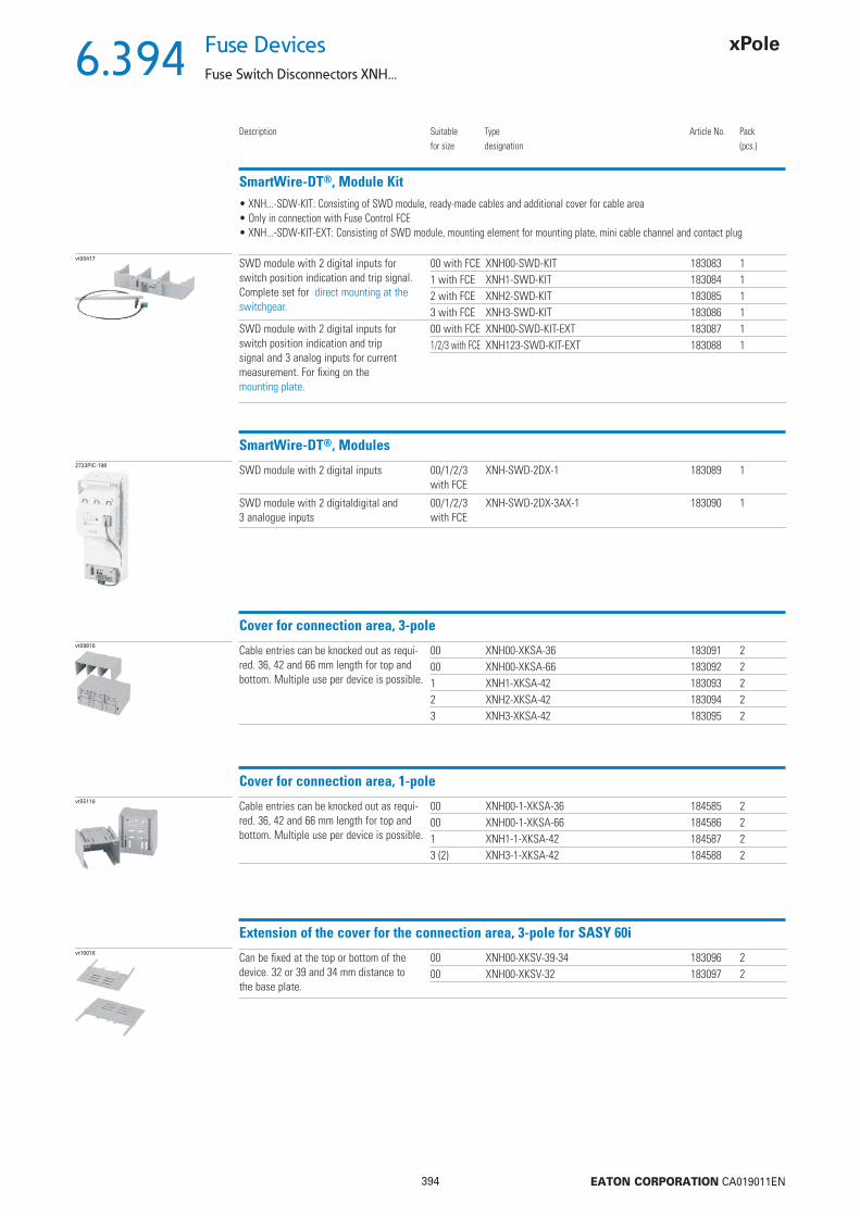
6.394
394 EATON CORPORATION CA019011EN
Fuse Devices
Fuse Switch Disconnectors XNH...
SmartWire-DT®, Module Kit
Description Suitablefor size
Typedesignation
Article No. Pack(pcs.)
• XNH...-SDW-KIT: Consisting of SWD module, ready-made cables and additional cover for cable area• Only in connection with Fuse Control FCE• XNH...-SDW-KIT-EXT: Consisting of SWD module, mounting element for mounting plate, mini cable channel and contact plug
vt00417 SWD module with 2 digital inputs for switch position indication and trip signal. Complete set for direct mounting at the switchgear.
00 with FCE XNH00-SWD-KIT 183083 11 with FCE XNH1-SWD-KIT 183084 12 with FCE XNH2-SWD-KIT 183085 13 with FCE XNH3-SWD-KIT 183086 1
SWD module with 2 digital inputs forswitch position indication and tripsignal and 3 analog inputs for currentmeasurement. For fi xing on themounting plate.
00 with FCE XNH00-SWD-KIT-EXT 183087 11/2/3 with FCE XNH123-SWD-KIT-EXT 183088 1
SmartWire-DT®, Modules2723PIC-198 SWD module with 2 digital inputs 00/1/2/3
with FCEXNH-SWD-2DX-1 183089 1
SWD module with 2 digitaldigital and 3 analogue inputs
00/1/2/3with FCE
XNH-SWD-2DX-3AX-1 183090 1
Cover for connection area, 3-polevt09816 Cable entries can be knocked out as requi-
red. 36, 42 and 66 mm length for top and bottom. Multiple use per device is possible.
00 XNH00-XKSA-36 183091 200 XNH00-XKSA-66 183092 21 XNH1-XKSA-42 183093 22 XNH2-XKSA-42 183094 23 XNH3-XKSA-42 183095 2
Cover for connection area, 1-polevt55116 Cable entries can be knocked out as requi-
red. 36, 42 and 66 mm length for top and bottom. Multiple use per device is possible.
00 XNH00-1-XKSA-36 184585 200 XNH00-1-XKSA-66 184586 21 XNH1-1-XKSA-42 184587 23 (2) XNH3-1-XKSA-42 184588 2
Extension of the cover for the connection area, 3-pole for SASY 60ivt10016 Can be fi xed at the top or bottom of the
device. 32 or 39 and 34 mm distance to the base plate.
00 XNH00-XKSV-39-34 183096 200 XNH00-XKSV-32 183097 2

6.395
395 EATON CORPORATION CA019011EN
Fuse DevicesFuse Switch Disconnectors XNH...
Reach-over protection, 3-pole for SASY 60i
Description Suitablefor size
Typedesignation
Article No. Pack(pcs.)
• Can be fi xed at the top or bottom of the device• For 32 or 39 and 34mm distance to the base plate
vt09916 For fl at connection or box terminal 00 XNH00-XKSS-39-34 183098 2XNH00-XKSS-32 183099 2
For BT2 box terminal 00 XNH00-XKSS-BT-39-34 183100 2XNH00-XKSS-BT-32 183101 2
For fl at connection or box terminal 1 XNH1-XKSS-39-34 183102 2XNH1-XKSS-32 183103 2
2 XNH2-XKSS-39-34 183104 2XNH2-XKSS-32 183105 2
3 XNH3-XKSS-39-34 183106 2XNH3-XKSS-32 183107 2
Height compensation adapter 20 mm, 3-polevt67015 Compensation adapter top/bottom
Level 70 => 9 0mm00 XNH00-XHAA-T/B 183108 2
Side compensation profi les Level 70 => 90 mm
00 XNH00-XHAA-R/L 183109 2
Cover supportsvt10616, vt10416 Top and bottom
Level 60, 70 mm00 XNH00-XCS-T/B 183110 2
SideLevel 32, 60, 70 mm
00 XNH00-XCS-R/L 183111 2
Top and bottom, sideLevel 32, 60, 70 mm
1, 2, 3 XNH123-XCS 183112 2
Current-theft protectionvt10916 For manipulation-protected blocking of the
inspection window00, 1, 2, 3 XNH-XSECUR 183113 1 Set
Note: 1 set includes current-theft protection for a 3-pole XNH.
DIN rail fastenervt68115 For mounting XNH disconnectors on
2x DIN rails EN 5002200 XNH00-XRAIL 183114 11 XNH1-XRAIL 183115 1
Locking devicevt11016 For locking with a padlock when using a
closed XNH disconnector00, 1, 2, 3 XNH-XLOCK 182993 1
Note: Padlock with a shackle diameter of 6 mm max.
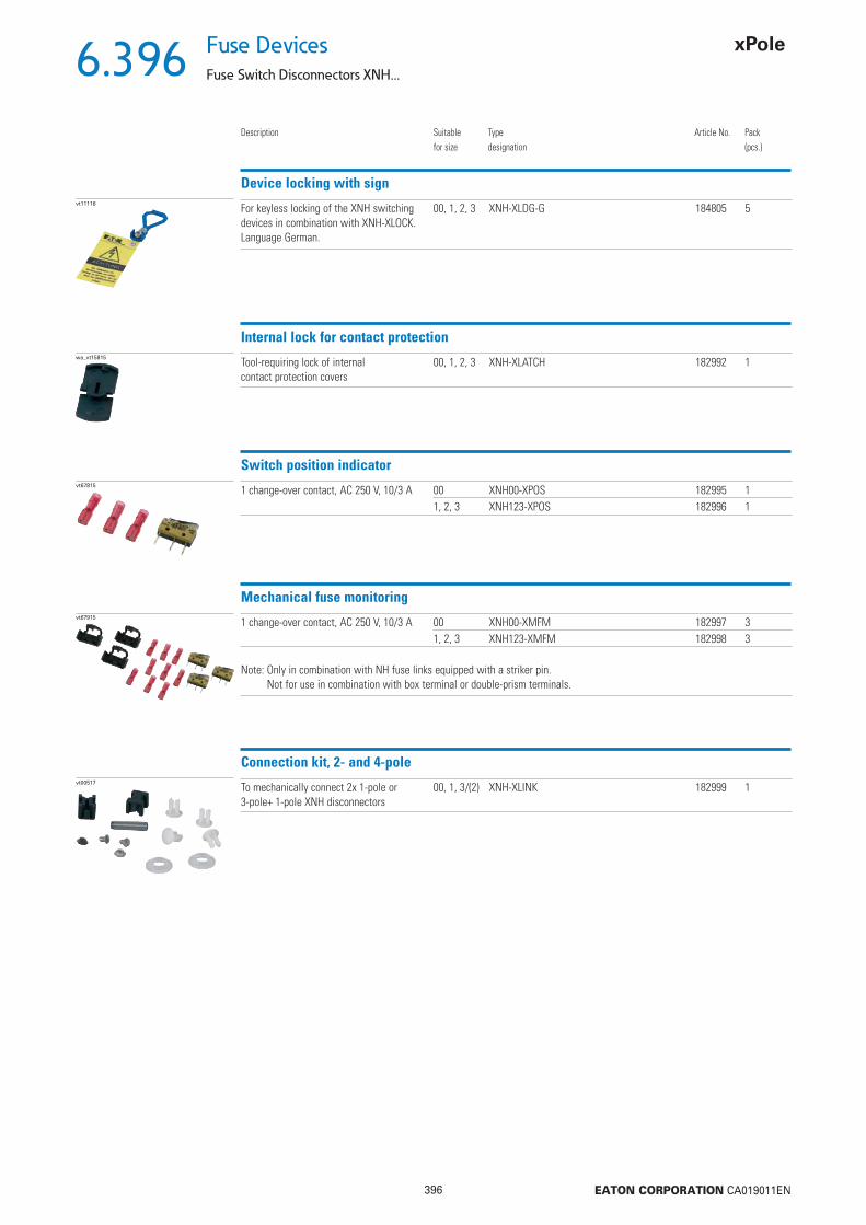
6.396
396 EATON CORPORATION CA019011EN
Fuse Devices
Fuse Switch Disconnectors XNH...
Description Suitablefor size
Typedesignation
Article No. Pack(pcs.)
Device locking with signvt11116 For keyless locking of the XNH switching
devices in combination with XNH-XLOCK.Language German.
00, 1, 2, 3 XNH-XLDG-G 184805 5
Internal lock for contact protectionwa_vt15815 Tool-requiring lock of internal
contact protection covers00, 1, 2, 3 XNH-XLATCH 182992 1
Switch position indicatorvt67815 1 change-over contact, AC 250 V, 10/3 A 00 XNH00-XPOS 182995 1
1, 2, 3 XNH123-XPOS 182996 1
Mechanical fuse monitoringvt67915 1 change-over contact, AC 250 V, 10/3 A 00 XNH00-XMFM 182997 3
1, 2, 3 XNH123-XMFM 182998 3
Note: Only in combination with NH fuse links equipped with a striker pin.Not for use in combination with box terminal or double-prism terminals.
Connection kit, 2- and 4-polevt00517 To mechanically connect 2x 1-pole or
3-pole+ 1-pole XNH disconnectors00, 1, 3/(2) XNH-XLINK 182999 1

6.397
397 EATON CORPORATION CA019011EN
Fuse DevicesFuse Switch Disconnectors XNH...
Description Suitablefor size
Typedesignation
Article No. Pack(pcs.)
Connection technology
vt68215 1,5 - 50 mm2, Cu 00 XNH00-XCT 183002 325 - 150 mm2, Cu 1 XNH1-XCT 183003 325 - 240 mm2, Cu 2 XNH2-XCT 183004 3CU-BAND-11x21x1 3 XNH3-XCT 183005 3
Clamp-type terminal
vt67515 10 - 70 mm2, Cu/Al 00 XNH00-XPRC 183006 370 - 150 mm2, Cu/Al 1 XNH1-XPRC 183007 3120 - 240 mm2, Cu/Al 2 XNH2-XPRC 183008 3120 - 300 mm2, Cu/Al 3 XNH3-XPRC 183009 3
Prism terminal
vt67315 2 x 70 - 95 mm2, Cu/Al 1 XNH1-X2PRC 183010 32 x 120 - 150 mm2, Cu/Al 2 XNH2-X2PRC 183011 32 x 120 - 240 mm2, Cu/Al 3 XNH3-X2PRC 183012 3
Double-prism terminal
vt68615 35 - 150 mm², Cu/Al 1 XNH1-BT 183000 395 - 300 mm², Cu/Al 2, 3 XNH23-BT 183001 3
Note: Box terminal and double-prism terminal not for use in combination with mechanical fuse monitoring XNH…-XMFM.
Box terminal
Spare handle cover, 3-polevt08016 Cover for XNH disconnector Basic 00 XNH00-XGRIP 183013 1
1 XNH1-XGRIP 183014 12 XNH2-XGRIP 183015 13 XNH3-XGRIP 183016 1
vt08116 Cover for XNH disconnector with Fuse Control FCL
00 XNH00-XGRIP-FCL 183017 11 XNH1-XGRIP-FCL 183018 12 XNH2-XGRIP-FCL 183019 13 XNH3-XGRIP-FCL 183020 1
vt08116 Cover for XNH disconnector with Fuse Control FCE
00 XNH00-XGRIP-FCE 183021 11 XNH1-XGRIP-FCE 183022 12 XNH2-XGRIP-FCE 183023 13 XNH3-XGRIP-FCE 183024 1
Note: FCL and FCE can only be used with fuse links equipped with live handle straps.
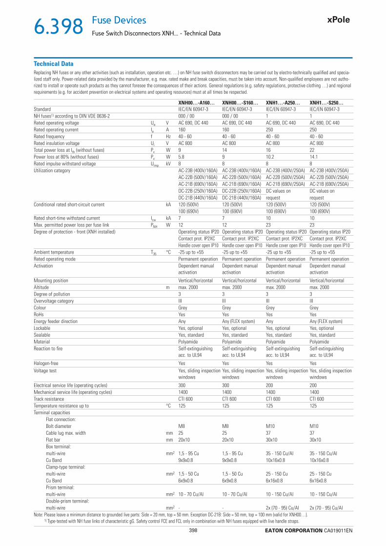
6.398
398 EATON CORPORATION CA019011EN
Fuse Devices
Fuse Switch Disconnectors XNH... - Technical Data
Replacing NH fuses or any other activities (such as installation, operation etc. …) on NH fuse switch disconnectors may be carried out by electro-technically qualifi ed and specia-lized staff only. Power-related data provided by the manufacturer, e.g. max. rated make and break capacities, must be taken into account. Non-qualifi ed employees are not autho-rized to install or operate such products as they cannot foresee the consequences of their actions. General regulations (e.g. safety regulations, protective clothing …) and regional requirements (e.g. for accident prevention on electrical systems and operating resources) must at all times be respected.
Technical Data
XNH00…-A160… XNH00…-S160… XNH1…-A250… XNH1…-S250…Standard IEC/EN 60947-3 IEC/EN 60947-3 IEC/EN 60947-3 IEC/EN 60947-3NH fuses1) according to DIN VDE 0636-2 000 / 00 000 / 00 1 1Rated operating voltage Ue V AC 690, DC 440 AC 690, DC 440 AC 690, DC 440 AC 690, DC 440Rated operating current Ie A 160 160 250 250Rated frequency f Hz 40 - 60 40 - 60 40 - 60 40 - 60Rated insulation voltage Ui V AC 800 AC 800 AC 800 AC 800Total power loss at Ith (without fuses) Pv W 9 14 16 22Power loss at 80% (without fuses) Pv W 5.8 9 10.2 14.1Rated impulse withstand voltage Uimp kV 8 8 8 8Utilization category AC-23B (400V/160A) AC-23B (400V/160A) AC-23B (400V/250A) AC-23B (400V/250A)
AC-22B (500V/160A) AC-22B (500V/160A) AC-22B (500V/250A) AC-22B (500V/250A)AC-21B (690V/160A) AC-21B (690V/160A) AC-21B (690V/250A) AC-21B (690V/250A)DC-22B (250V/160A) DC-22B (250V/160A) DC values on DC values onDC-21B (440V/160A) DC-21B (440V/160A) request request
Conditional rated short-circuit current kA 120 (500V) 120 (500V) 120 (500V) 120 (500V)100 (690V) 100 (690V) 100 (690V) 100 (690V)
Rated short-time withstand current Icw kA 7 7 10 10Max. permitted power loss per fuse link PNH W 12 12 23 23Degree of protection - front (XNH installed) Operating status IP20 Operating status IP20 Operating status IP20 Operating status IP20
Contact prot. IP2XC Contact prot. IP2XC Contact prot. IP2XC Contact prot. IP2XCHandle cover open IP10 Handle cover open IP10 Handle cover open IP10 Handle cover open IP10
Ambient temperature T35 °C -25 up to +55 -25 up to +55 -25 up to +55 -25 up to +55Rated operating mode Permanent operation Permanent operation Permanent operation Permanent operationActivation Dependent manual
activationDependent manual activation
Dependent manual activation
Dependent manual activation
Mounting position Vertical/horizontal Vertical/horizontal Vertical/horizontal Vertical/horizontalAltitude m max. 2000 max. 2000 max. 2000 max. 2000Degree of pollution 3 3 3 3Overvoltage category III III III IIIColour Grey Grey Grey GreyRoHs Yes Yes Yes YesEnergy feeder direction Any Any (FLEX system) Any Any (FLEX system)Lockable Yes, optional Yes, optional Yes, optional Yes, optionalSealable Yes, standard Yes, standard Yes, standard Yes, standardMaterial Polyamide Polyamide Polyamide PolyamideReaction to fi re Self-extinguishing
acc. to UL94Self-extinguishing acc. to UL94
Self-extinguishing acc. to UL94
Self-extinguishing acc. to UL94
Halogen-free Yes Yes Yes YesVoltage test Yes, sliding inspection
windowsYes, sliding inspection windows
Yes, sliding inspection windows
Yes, sliding inspection windows
Electrical service life (operating cycles) 300 300 200 200Mechanical service life (operating cycles) 1400 1400 1400 1400Track resistance CTI 600 CTI 600 CTI 600 CTI 600Temperature resistance up to °C 125 125 125 125Terminal capacities
Flat connection:Bolt diameter M8 M8 M10 M10Cable lug max. width mm 25 25 37 37Flat bar mm 20x10 20x10 30x10 30x10Box terminal:multi-wire mm2 1,5 - 95 Cu 1,5 - 95 Cu 35 - 150 Cu/Al 35 - 150 Cu/AlCu Band 9x9x0.8 9x9x0.8 10x16x0.8 10x16x0.8Clamp-type terminal:multi-wire mm2 1,5 - 50 Cu 1,5 - 50 Cu 25 - 150 Cu 25 - 150 CuCu Band 6x9x0.8 6x9x0.8 6x16x0.8 6x16x0.8Prism terminal:multi-wire mm2 10 - 70 Cu/Al 10 - 70 Cu/Al 10 - 150 Cu/Al 10 - 150 Cu/AlDouble-prism terminal:multi-wire mm2 - - 2x (70 - 95) Cu/Al 2x (70 - 95) Cu/Al
Note: Please leave a minimum distance to grounded live parts: Side = 20 mm, top = 50 mm. Exception DC-21B: Side = 50 mm, top = 100 mm (valid for XNH00…). 1) Type-tested with NH fuse links of characteristic gG. Safety control FCE and FCL only in combination with NH fuses equipped with live handle straps.
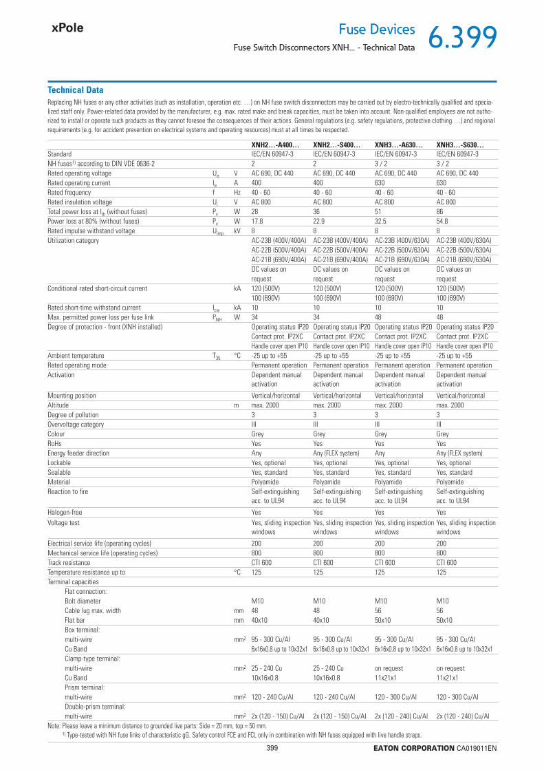
6.399
399 EATON CORPORATION CA019011EN
Fuse DevicesFuse Switch Disconnectors XNH... - Technical Data
Replacing NH fuses or any other activities (such as installation, operation etc. …) on NH fuse switch disconnectors may be carried out by electro-technically qualifi ed and specia-lized staff only. Power-related data provided by the manufacturer, e.g. max. rated make and break capacities, must be taken into account. Non-qualifi ed employees are not autho-rized to install or operate such products as they cannot foresee the consequences of their actions. General regulations (e.g. safety regulations, protective clothing …) and regional requirements (e.g. for accident prevention on electrical systems and operating resources) must at all times be respected.
Technical Data
XNH2…-A400… XNH2…-S400… XNH3…-A630… XNH3…-S630…Standard IEC/EN 60947-3 IEC/EN 60947-3 IEC/EN 60947-3 IEC/EN 60947-3NH fuses1) according to DIN VDE 0636-2 2 2 3 / 2 3 / 2Rated operating voltage Ue V AC 690, DC 440 AC 690, DC 440 AC 690, DC 440 AC 690, DC 440Rated operating current Ie A 400 400 630 630Rated frequency f Hz 40 - 60 40 - 60 40 - 60 40 - 60Rated insulation voltage Ui V AC 800 AC 800 AC 800 AC 800Total power loss at Ith (without fuses) Pv W 28 36 51 86Power loss at 80% (without fuses) Pv W 17.8 22.9 32.5 54.8Rated impulse withstand voltage Uimp kV 8 8 8 8Utilization category AC-23B (400V/400A) AC-23B (400V/400A) AC-23B (400V/630A) AC-23B (400V/630A)
AC-22B (500V/400A) AC-22B (500V/400A) AC-22B (500V/630A) AC-22B (500V/630A) AC-21B (690V/400A) AC-21B (690V/400A) AC-21B (690V/630A) AC-21B (690V/630A)DC values on DC values on DC values on DC values onrequest request request request
Conditional rated short-circuit current kA 120 (500V) 120 (500V) 120 (500V) 120 (500V)100 (690V) 100 (690V) 100 (690V) 100 (690V)
Rated short-time withstand current Icw kA 10 10 10 10Max. permitted power loss per fuse link PNH W 34 34 48 48Degree of protection - front (XNH installed) Operating status IP20 Operating status IP20 Operating status IP20 Operating status IP20
Contact prot. IP2XC Contact prot. IP2XC Contact prot. IP2XC Contact prot. IP2XCHandle cover open IP10 Handle cover open IP10 Handle cover open IP10 Handle cover open IP10
Ambient temperature T35 °C -25 up to +55 -25 up to +55 -25 up to +55 -25 up to +55Rated operating mode Permanent operation Permanent operation Permanent operation Permanent operationActivation Dependent manual
activationDependent manual activation
Dependent manual activation
Dependent manual activation
Mounting position Vertical/horizontal Vertical/horizontal Vertical/horizontal Vertical/horizontalAltitude m max. 2000 max. 2000 max. 2000 max. 2000Degree of pollution 3 3 3 3Overvoltage category III III III IIIColour Grey Grey Grey GreyRoHs Yes Yes Yes YesEnergy feeder direction Any Any (FLEX system) Any Any (FLEX system)Lockable Yes, optional Yes, optional Yes, optional Yes, optionalSealable Yes, standard Yes, standard Yes, standard Yes, standardMaterial Polyamide Polyamide Polyamide PolyamideReaction to fi re Self-extinguishing
acc. to UL94Self-extinguishing acc. to UL94
Self-extinguishing acc. to UL94
Self-extinguishing acc. to UL94
Halogen-free Yes Yes Yes YesVoltage test Yes, sliding inspection
windowsYes, sliding inspection windows
Yes, sliding inspection windows
Yes, sliding inspection windows
Electrical service life (operating cycles) 200 200 200 200Mechanical service life (operating cycles) 800 800 800 800Track resistance CTI 600 CTI 600 CTI 600 CTI 600Temperature resistance up to °C 125 125 125 125Terminal capacities
Flat connection:Bolt diameter M10 M10 M10 M10Cable lug max. width mm 48 48 56 56Flat bar mm 40x10 40x10 50x10 50x10Box terminal:multi-wire mm2 95 - 300 Cu/Al 95 - 300 Cu/Al 95 - 300 Cu/Al 95 - 300 Cu/AlCu Band 6x16x0.8 up to 10x32x1 6x16x0.8 up to 10x32x1 6x16x0.8 up to 10x32x1 6x16x0.8 up to 10x32x1Clamp-type terminal:multi-wire mm2 25 - 240 Cu 25 - 240 Cu on request on requestCu Band 10x16x0.8 10x16x0.8 11x21x1 11x21x1Prism terminal:multi-wire mm2 120 - 240 Cu/Al 120 - 240 Cu/Al 120 - 300 Cu/Al 120 - 300 Cu/AlDouble-prism terminal:multi-wire mm2 2x (120 - 150) Cu/Al 2x (120 - 150) Cu/Al 2x (120 - 240) Cu/Al 2x (120 - 240) Cu/Al
Note: Please leave a minimum distance to grounded live parts: Side = 20 mm, top = 50 mm. 1) Type-tested with NH fuse links of characteristic gG. Safety control FCE and FCL only in combination with NH fuses equipped with live handle straps.
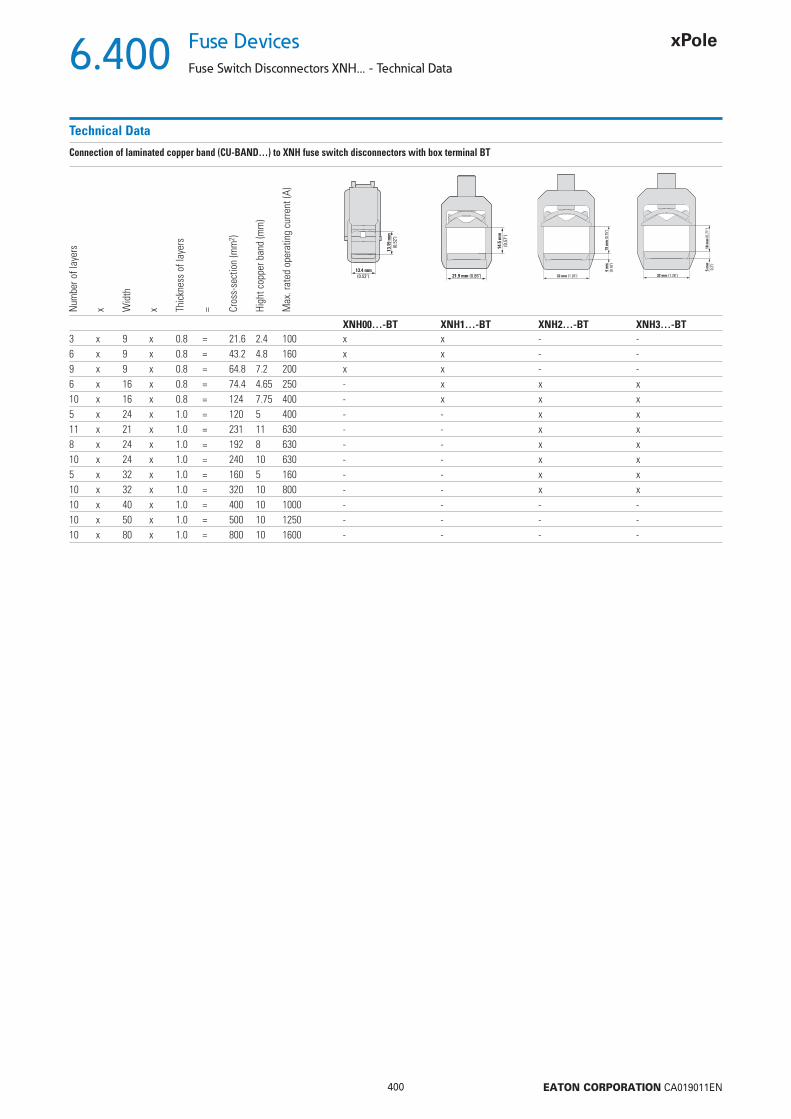
6.400
400 EATON CORPORATION CA019011EN
Fuse Devices
Fuse Switch Disconnectors XNH... - Technical Data
Technical Data
Connection of laminated copper band (CU-BAND…) to XNH fuse switch disconnectors with box terminal BT
Num
ber o
f lay
ers
x Wid
th
x Thic
knes
s of
laye
rs
= Cros
s-se
ctio
n (m
m2 )
High
t cop
per b
and
(mm
)
Max
. rat
ed o
pera
ting
curre
nt (A
)
13
.19
mm
(0.5
2")
13.4 mm
(0.53")
14
.5 m
m
(0.5
7")
21.9 mm (0.86")
19
mm
(0.7
5")
4 m
m
(0.1
6")
32 mm (1.26")
18 m
m (0
.71"
)5 m
m
0.2"
)
32 mm (1.26")
XNH00…-BT XNH1…-BT XNH2…-BT XNH3…-BT3 x 9 x 0.8 = 21.6 2.4 100 x x - -6 x 9 x 0.8 = 43.2 4.8 160 x x - -9 x 9 x 0.8 = 64.8 7.2 200 x x - -6 x 16 x 0.8 = 74.4 4.65 250 - x x x10 x 16 x 0.8 = 124 7.75 400 - x x x5 x 24 x 1.0 = 120 5 400 - - x x11 x 21 x 1.0 = 231 11 630 - - x x8 x 24 x 1.0 = 192 8 630 - - x x10 x 24 x 1.0 = 240 10 630 - - x x5 x 32 x 1.0 = 160 5 160 - - x x10 x 32 x 1.0 = 320 10 800 - - x x10 x 40 x 1.0 = 400 10 1000 - - - -10 x 50 x 1.0 = 500 10 1250 - - - -10 x 80 x 1.0 = 800 10 1600 - - - -
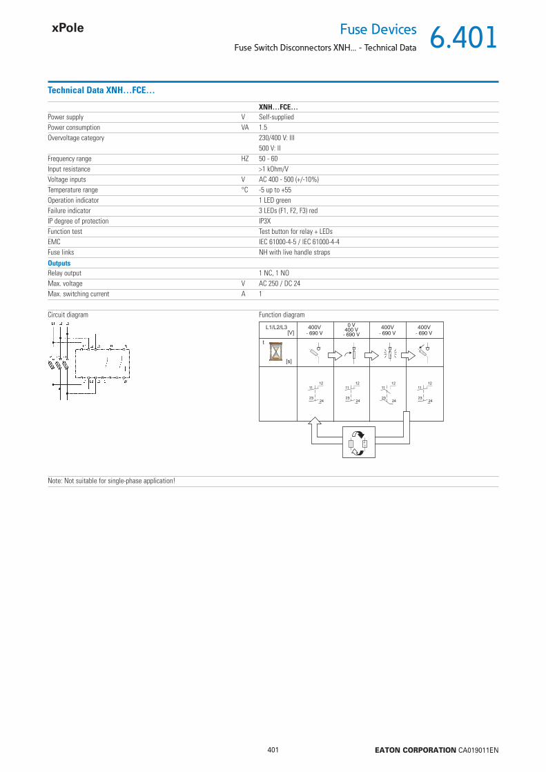
6.401
401 EATON CORPORATION CA019011EN
Fuse DevicesFuse Switch Disconnectors XNH... - Technical Data
Technical Data XNH…FCE…
XNH…FCE…Power supply V Self-suppliedPower consumption VA 1.5Overvoltage category 230/400 V: III
500 V: IIFrequency range HZ 50 - 60Input resistance >1 kOhm/VVoltage inputs V AC 400 - 500 (+/-10%)Temperature range °C -5 up to +55Operation indicator 1 LED greenFailure indicator 3 LEDs (F1, F2, F3) redIP degree of protection IP3XFunction test Test button for relay + LEDsEMC IEC 61000-4-5 / IEC 61000-4-4Fuse links NH with live handle strapsOutputsRelay output 1 NC, 1 NOMax. voltage V AC 250 / DC 24Max. switching current A 1
Circuit diagram Function diagram
Note: Not suitable for single-phase application!

6.402
402 EATON CORPORATION CA019011EN
Fuse Devices
Fuse Switch Disconnectors XNH... - Technical Data
Product range XNH.-SWD-KIT
Technical Data XNH.-SWD-KIT
XNH00-SWD-KIT XNH1-SWD-KIT XNH2-SWD-KIT XNH3-SWD-KITBasic function SmartWire-DT® module for direct connectionAccessories SmartWire-DT® XNH module (NH fuse switch disconnector)Compatible with the devices XNH00-FCE-… XNH1-FCE-… XNH2-FCE-… XNH3-FCE-…Scope of delivery Base module with 2 digital inputs for XNH
Switch position indicator (1 change-over contact, AC 250 V, 10/3 A)ver for connection area - bottomMini cable ductContact plug 4-poleControl cable 0.75 mm2, 4 units
Description Mounting onto XNH fuse switch disconnectorSignals Switch position XNH
Fuse trippedConnection to SmartWire-DT Yes
XNH00-SWD-KIT XNH1-SWD-KIT XNH2-SWD-KIT XNH3-SWD-KITGeneral informationStandards and regulations Immunity:
IEC 61131-2: 2007 include test accordingIEC 61000-4-2: 2008IEC 61000-4-3: 2006+A1:2007+A2:2010IEC 61000-4-4: 2012IEC 61000-4-6: 2008IEC 61000-4-8: 2010Emission:IEC 61131-2: 2007IEC/CISPR 11:2009, mod. + A1:2010, Group 1, Class A
Dimensions (W x H x D) mm 92 x 51 x 26.5Weight kg 0.07Installation On the cover of the cable area of the XNH-…Mounting position Same as XNH-…Mechanical ambient conditionsDegree of protection (IEC/EN 60529, EN50178, VBG 4) IP2XElectromagnetic compatibility (EMC)Overvoltage category IIDegree of pollution 2Electrostatic discharge (IEC/EN 61131-2:2008)
Air discharge (Level 3) kV 8Contact discharge (Level 2) kV 4
Electromagnetic fi elds (IEC/EN 61131-2:2008)80 - 1000 MHz V/m 101.4 - 2 GHz V/m 32 - 2.7 GHz V/m 3
Radio interference suppression SmartWire-DTRadio interference suppression EN 55011 Class A
Burst (IEC/EN 61131-2:2008, Level 3)SmartWire-DT cables Signal cables kV 2CAN/DP Bus cables SmartWire-DT cables kV 2
Inrush (IEC/EN 61131-2:2008, Level 3) V 10
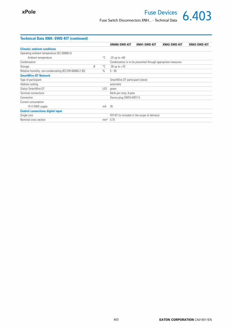
6.403
403 EATON CORPORATION CA019011EN
Fuse DevicesFuse Switch Disconnectors XNH... - Technical Data
Technical Data XNH.-SWD-KIT (continued)XNH00-SWD-KIT XNH1-SWD-KIT XNH2-SWD-KIT XNH3-SWD-KIT
Climatic ambient conditionsOperating ambient temperature (IEC 60068-2)
Ambient temperature °C -25 up to +60Condensation Condensation is to be prevented through appropriate measuresStorage °C -30 up to +70Relative humidity, non-condensating (IEC/EN 60068-2-30) % 5 - 95SmartWire-DT NetworkType of participant SmartWire-DT participant (slave)Address setting automaticStatus SmartWire-DT LED greenTerminal connections Multi-pin strip, 8-poleConnection Device plug SWD4-8SF2-5Current consumption
15-V-SWD supply mA 35Control connections digital inputSingle core FEP-6Y (is included in the scope of delivery)Nominal cross section mm2 0.75

6.404
404 EATON CORPORATION CA019011EN
Fuse Devices
Fuse Switch Disconnectors XNH... - Technical Data
Product range XNH...-SWD-KIT-EXT
Technical Data XNH...-SWD-KIT-EXT
XNH00-SWD-KIT-EXT XNH123-SWD-KIT-EXTBasic function SmartWire-DT® module for direct connectionAccessories SmartWire-DT® XNH module (NH fuse switch disconnector)Compatible with the devices XNH00-FCE-… XNH1(2/3)-FCE-…Scope of delivery SWD module with 2 digital inputs and 3 analog inputs
Without change-overWithout control cablesFixing element for mounting plateMini cable ductContact plug 4-pole and 6-pole
Description Installation on the mounting plateSignals Current measurement
Switch position XNHFuse tripped
Connection to SmartWire-DT Yes
XNH00-SWD-KIT-EXT XNH123-SWD-KIT-EXTGeneral informationStandards and regulations Immunity:
IEC 61131-2: 2007 include test accordingIEC 61000-4-2: 2008IEC 61000-4-3: 2006+A1:2007+A2:2010IEC 61000-4-4: 2012IEC 61000-4-6: 2008IEC 61000-4-8: 2010Emission:IEC 61131-2: 2007IEC/CISPR 11:2009, mod. + A1:2010, Group 1, Class A
Dimensions (W x H x D) mm 92 x 51 x 26.5Weight kg 0.07Installation On mounting plateMounting position Same as XNH-…Mechanical ambient conditionsDegree of protection (IEC/EN 60529, EN50178, VBG 4) IP2XElectromagnetic compatibility (EMC)Overvoltage category IIDegree of pollution 2Electrostatic discharge (IEC/EN 61131-2:2008)
Air discharge (Level 3) kV 8Contact discharge (Level 2) kV 4
Electromagnetic fi elds (IEC/EN 61131-2:2008)80 - 1000 MHz V/m 101.4 - 2 GHz V/m 32 - 2.7 GHz V/m 3
Radio interference suppression SmartWire-DTRadio interference suppression EN 55011 Class A
Burst (IEC/EN 61131-2:2008, Level 3)SmartWire-DT cablesSignal cables kV 2CAN/DP Bus cablesSmartWire-DT cables kV 2
Inrush (IEC/EN 61131-2:2008, Level 3) V 10

6.405
405 EATON CORPORATION CA019011EN
Fuse DevicesFuse Switch Disconnectors XNH... - Technical Data
Technical Data XNH...-SWD-KIT-EXT (continued)XNH123-SWD-KIT-EXT XNH3-SWD-KIT
Climatic ambient conditionsOperating ambient temperature (IEC 60068-2)
Ambient temperature °C -25 up to +60Condensation Condensation is to be prevented through appropriate measuresStorage J °C -30 up to +70Relative humidity, non-condensating (IEC/EN 60068-2-30) % 5 - 95SmartWire-DT NetworkType of participant SmartWire-DT participant (slave)Address setting automaticStatus SmartWire-DT LED greenTerminal connections Multi-pin strip, 8-poleConnection Device plug SWD4-8SF2-5Current consumption
15-V-SWD supply mA 35Control connections digital inputSingle core FEP-6Y (not included in the scope of delivery)Nominal cross section mm2 0.75
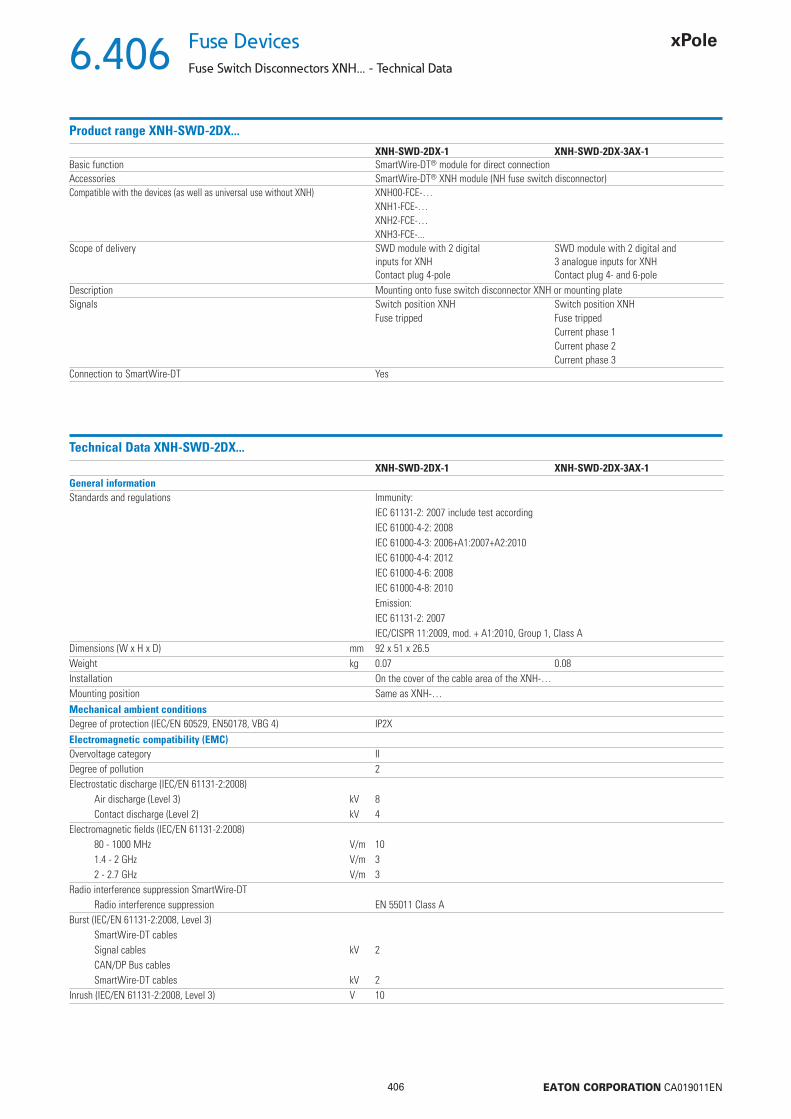
6.406
406 EATON CORPORATION CA019011EN
Fuse Devices
Fuse Switch Disconnectors XNH... - Technical Data
Product range XNH-SWD-2DX...
Technical Data XNH-SWD-2DX...
XNH-SWD-2DX-1 XNH-SWD-2DX-3AX-1Basic function SmartWire-DT® module for direct connectionAccessories SmartWire-DT® XNH module (NH fuse switch disconnector)Compatible with the devices (as well as universal use without XNH) XNH00-FCE-…
XNH1-FCE-…XNH2-FCE-…XNH3-FCE-...
Scope of delivery SWD module with 2 digitalinputs for XNHContact plug 4-pole
SWD module with 2 digital and3 analogue inputs for XNHContact plug 4- and 6-pole
Description Mounting onto fuse switch disconnector XNH or mounting plateSignals Switch position XNH Switch position XNH
Fuse tripped Fuse trippedCurrent phase 1Current phase 2Current phase 3
Connection to SmartWire-DT Yes
XNH-SWD-2DX-1 XNH-SWD-2DX-3AX-1General informationStandards and regulations Immunity:
IEC 61131-2: 2007 include test accordingIEC 61000-4-2: 2008IEC 61000-4-3: 2006+A1:2007+A2:2010IEC 61000-4-4: 2012IEC 61000-4-6: 2008IEC 61000-4-8: 2010Emission:IEC 61131-2: 2007IEC/CISPR 11:2009, mod. + A1:2010, Group 1, Class A
Dimensions (W x H x D) mm 92 x 51 x 26.5Weight kg 0.07 0.08Installation On the cover of the cable area of the XNH-…Mounting position Same as XNH-…Mechanical ambient conditionsDegree of protection (IEC/EN 60529, EN50178, VBG 4) IP2XElectromagnetic compatibility (EMC)Overvoltage category IIDegree of pollution 2Electrostatic discharge (IEC/EN 61131-2:2008)
Air discharge (Level 3) kV 8Contact discharge (Level 2) kV 4
Electromagnetic fi elds (IEC/EN 61131-2:2008)80 - 1000 MHz V/m 101.4 - 2 GHz V/m 32 - 2.7 GHz V/m 3
Radio interference suppression SmartWire-DTRadio interference suppression EN 55011 Class A
Burst (IEC/EN 61131-2:2008, Level 3)SmartWire-DT cablesSignal cables kV 2CAN/DP Bus cablesSmartWire-DT cables kV 2
Inrush (IEC/EN 61131-2:2008, Level 3) V 10

6.407
407 EATON CORPORATION CA019011EN
Fuse DevicesFuse Switch Disconnectors XNH... - Technical Data
Technical Data XNH-SWD-2DX... (continued)XNH-SWD-2DX-1 XNH-SWD-2DX-3AX-1
Climatic ambient conditionsOperating ambient temperature (IEC 60068-2)
Ambient temperature °C -25 up to +60Condensation Condensation is to be prevented through appropriate measuresStorage J °C -30 up to +70Relative humidity, non-condensating (IEC/EN 60068-2-30) % 5 - 95SmartWire-DT NetworkType of participant SmartWire-DT participant (slave)Address setting automaticStatus SmartWire-DT LED greenTerminal connections Multi-pin strip, 8-poleConnection Device plug SWD4-8SF2-5Current consumption
15-V-SWD supply mA 35Control connections digital inputSingle core FEP-6Y (not included in the scope of delivery)Nominal cross section mm2 0.75Connection Contact plug, 4-pole
(included in the scope of delivery)Contact plug, 4- and 6-pole (included in the scope of delivery)

6.408
408 EATON CORPORATION CA019011EN
Fuse Devices
Fuse Switch Disconnectors XNH... - Technical Data
Dimensional drawings
XNH00-A160..., XNH00-FCL-A160...
106
66
44106
204
102
102
187 25
4
4.5
4212
019
520
4
33
84
45
16.57
33 49
⌀ 7⌀
9
75
11
1230DIM-352
XNH00-FCE-A160...,
106
66
44
106
204
102
102
187 25
4
4.5
4212
019
520
4
84
117
45
16.57
49
⌀ 7⌀
9
75
11
33 33
1230DIM-353

6.409
409 EATON CORPORATION CA019011EN
Fuse DevicesFuse Switch Disconnectors XNH... - Technical Data
Dimensional drawings
1x XNH00-1-A160...
102
187
5
195
4.5
204
4212
0
84
45
5016.5
7⌀
9
12
45
16.57
1230DIM-373, 1230DIM-374
195
4.5
204
100
102
187
5
4212
0
84
4516.5
7
⌀ 9
12
45
16.57
2x XNH00-1-A160...
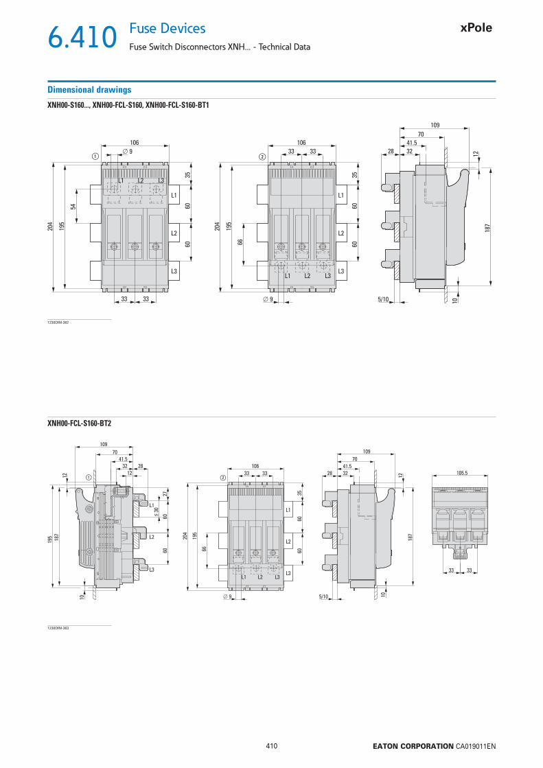
6.410
410 EATON CORPORATION CA019011EN
Fuse Devices
Fuse Switch Disconnectors XNH... - Technical Data
Dimensional drawings
XNH00-S160..., XNH00-FCL-S160, XNH00-FCL-S160-BT1
106
②①
187
10
195
204
54
6060
35
33
109
70
41.528 32
33
⌀ 9 12
106
195
204
66 6060
35
33 33
L1
L2
L3
L1 L2 L3
L1 L2 L3
L1
L2
L3
⌀ 9 5/10
1230DIM-362
XNH00-FCL-S160-BT2
187
10
109
70
105.541.5
28 32
12
106
195
204
66 6060
35
33 33
L1 L2 L3
L1
L2
L3
L1
L2
L3 33 33
⌀ 9 5/10
6060≦
30
27
187
195
10
109
7041.5
283212
12 ②①
1230DIM-363
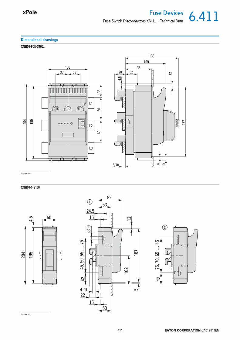
6.411
411 EATON CORPORATION CA019011EN
Fuse DevicesFuse Switch Disconnectors XNH... - Technical Data
Dimensional drawings
XNH00-FCE-S160...
106
4.5
133
33 33
187
4 10
109
7028 32
12
5/10
195
204
6060
35L1
L2
L3
1230DIM-364
XNH00-1-S160
102
187
5
195
4.5
204
42
92
53
5024.5
15
⌀ 9
12
5315
4-1022
4275
, 70,
65
… 4
5
45, 5
0, 5
5 …
75
②
①
1230DIM-375

6.412
412 EATON CORPORATION CA019011EN
Fuse Devices
Fuse Switch Disconnectors XNH... - Technical Data
Dimensional drawings
XNH1-A250..., XNH1-FCL-A250...
184
150
25
⌀ 1
1
⌀ 1
0.5
138
138
272
519
306
50
184
11770
3225
70
322558 58
429
8
306
185
46
1230DIM-355
XNH1-FCE-A250...
184
150
25
⌀ 1
1
138
306
50
184
429
8
306
⌀ 1
0.5
138
272
5
19
11770
3225
70
3225
185
46
148
58 58
1230DIM-359
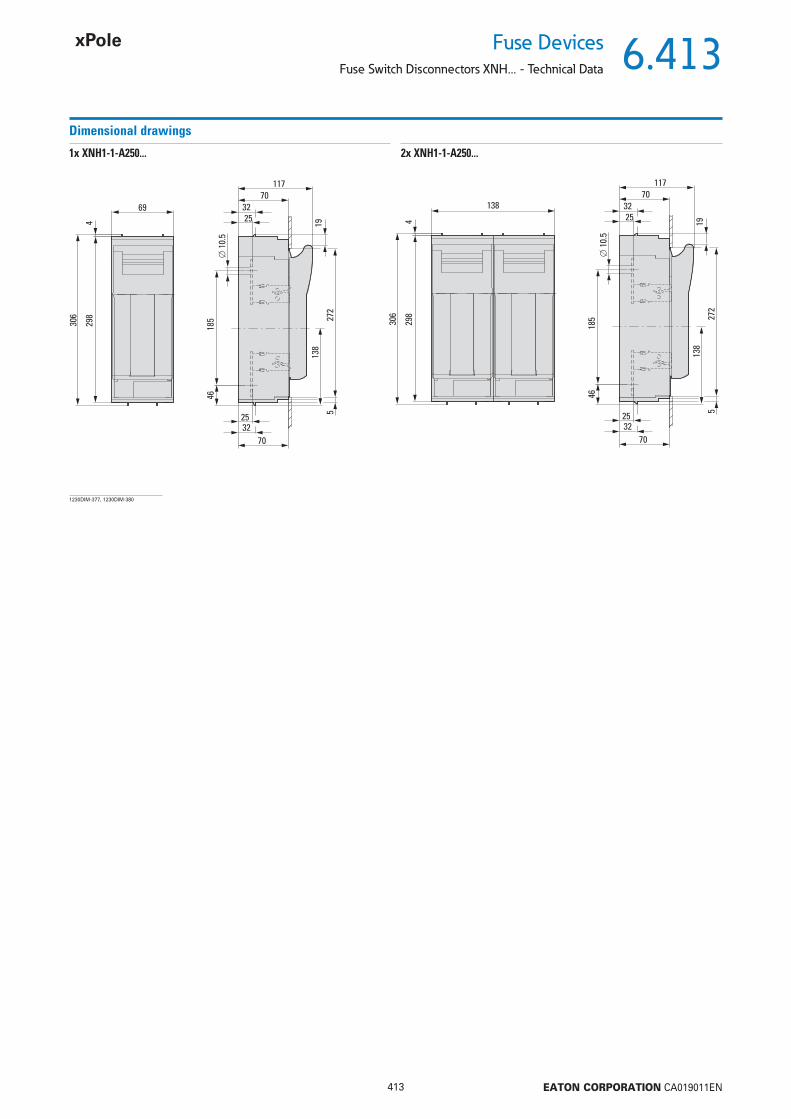
6.413
413 EATON CORPORATION CA019011EN
Fuse DevicesFuse Switch Disconnectors XNH... - Technical Data
Dimensional drawings
1x XNH1-1-A250...
⌀ 1
0.5
138
272
519
11770
3225
70
3225
185
4669
429
8
306
1230DIM-377, 1230DIM-380
⌀ 1
0.5
138
272
519
117
13870
3225
70
3225
185
46
429
8
306
2x XNH1-1-A250...

6.414
414 EATON CORPORATION CA019011EN
Fuse Devices
Fuse Switch Disconnectors XNH... - Technical Data
Dimensional drawings
XNH1-S250..., XNH1-FCL-S250...
272
519
102
6060
87
184
11770
32
25
7032
25.5
4-10
58 58429
8
306
L1
L2
L3
L1 L2 L3
⌀ 10.5
102
6060
98
184
58 58
429
8
306
L1
L2
L3
L1 L2 L3
⌀ 10.5②①
1230DIM-366
XNH1-FCE-S250...
272
5
19
184
11770
32
70148
32
58 58429
8
306
102
6060
L1
L2
L3
25
4-10
1230DIM-370

6.415
415 EATON CORPORATION CA019011EN
Fuse DevicesFuse Switch Disconnectors XNH... - Technical Data
Dimensional drawings
XNH2-A400..., XNH2-FCL-A400...
210
166
0
⌀ 1
1
⌀ 1
4
138
138
268
288
10 5
19
306
50
210
13490
7032
26
9070
322666 66
429
8
306
205
36
1230DIM-356
XNH2-FCE-A400...
25
⌀ 1
1
138
306
50
165
210
166
288
5
138
268
10
19
13490
7032
26
9070
3226
210
429
8
306
⌀ 1
4
205
36
66 66
1230DIM-360
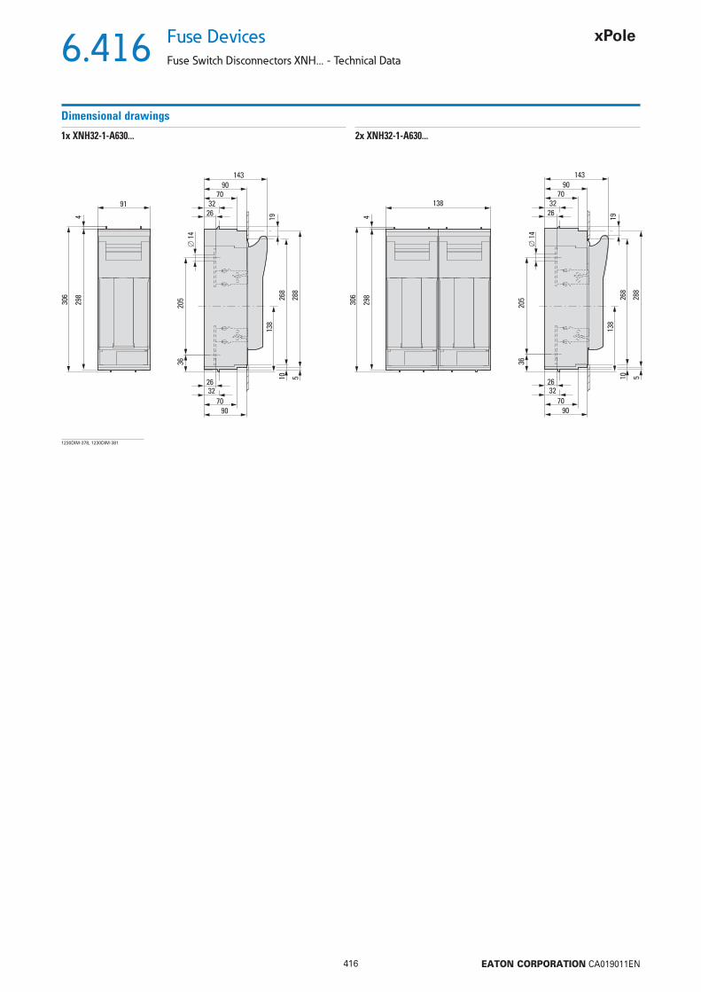
6.416
416 EATON CORPORATION CA019011EN
Fuse Devices
Fuse Switch Disconnectors XNH... - Technical Data
Dimensional drawings
⌀ 1
4
138
268
288
10 5
19
14390
7032
26
9070
3226
205
36
91
429
8
306
1230DIM-378, 1230DIM-381
⌀ 1
4
138
268
288
10 5
19
14390
7032
26
9070
3226
205
36
138
429
8
306
1x XNH32-1-A630... 2x XNH32-1-A630...
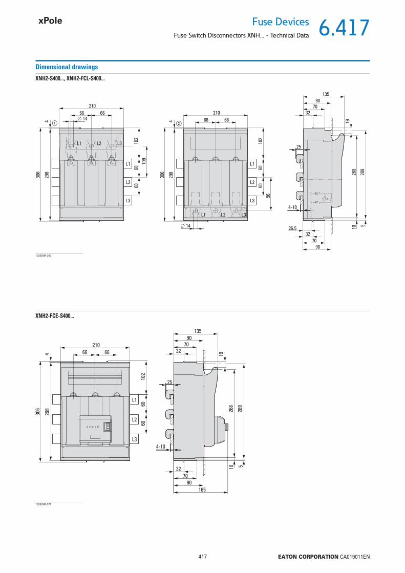
6.417
417 EATON CORPORATION CA019011EN
Fuse DevicesFuse Switch Disconnectors XNH... - Technical Data
Dimensional drawings
XNH2-S400..., XNH2-FCL-S400...
268
288
10
5
19
102
6060
96
210
13590
7032
25
9070
3226.5
4-10
66 66429
8
306
L1
L2
L3
L1 L2 L3
⌀ 14
102
6060
109
210
66 66
429
8
306
L1
L2
L3
L1 L2 L3
⌀ 14②①
1230DIM-367
XNH2-FCE-S400...
268
289
10 5
19
210
13590
7032
9070
165
32
66 66429
8
306
102
6060
L1
L2
L3
25
4-10
1230DIM-371
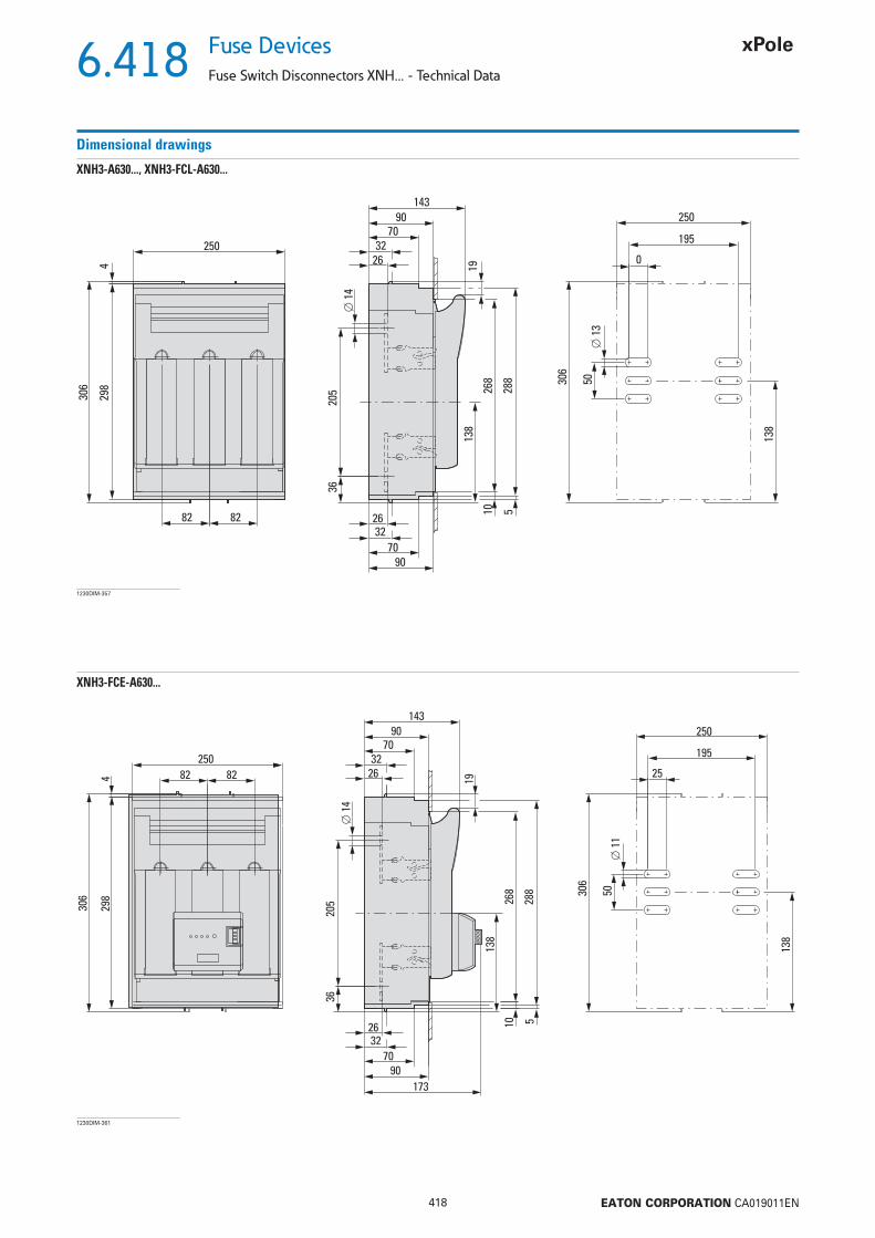
6.418
418 EATON CORPORATION CA019011EN
Fuse Devices
Fuse Switch Disconnectors XNH... - Technical Data
Dimensional drawings
XNH3-A630..., XNH3-FCL-A630...
250
195
0
⌀ 1
3
⌀ 1
4
138
138
268
288
10 5
19
306
50
250
14390
7032
26
9070
322682 82
429
8
306
205
36
1230DIM-357
XNH3-FCE-A630...
25
⌀ 1
1
138
306
50
173
250
195
288
5
138
268
10
19
14390
7032
26
9070
3226
250
429
8
306
⌀ 1
4
205
36
82 82
1230DIM-361

6.419
419 EATON CORPORATION CA019011EN
Fuse DevicesFuse Switch Disconnectors XNH... - Technical Data
Dimensional drawings
XNH3-S630..., XNH3-FCL-S630...
268
288
10
5
19
102
6060
96
250
14390
7032
25
9070
3226.5
4-10
82 82429
8
306
L1
L2
L3
L1 L2 L3
⌀ 14
102
6060
109
250
82 82
429
8
306
L1
L2
L3
L1 L2 L3
⌀ 14②①
1230DIM-368
XNH3-FCE-S630...
268
289
10 5
19
250
14390
7032
9070
173
32
82 82429
8
306
102
6060
L1
L2
L3
25
4-10
1230DIM-372

6.420
420 EATON CORPORATION CA019011EN
Fuse Devices
Fuse Switch Disconnectors XNH... - Technical Data
Dimensional drawings
XNH-SWD-2DX-1...
51
mm
(2.0
1")
92 mm (3.62")
26.5 mm
(1.04")
22.5 mm
(0.89")
2723DIM-55
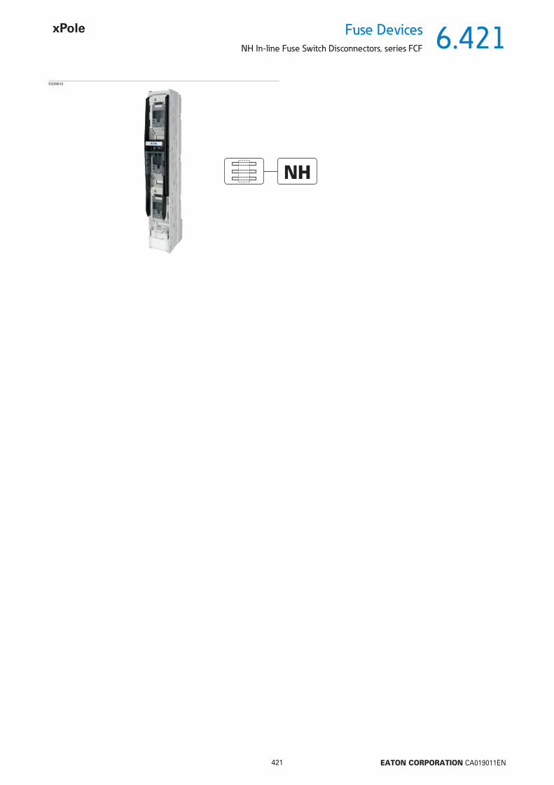
6.421
421 EATON CORPORATION CA019011EN
Fuse DevicesNH In-line Fuse Switch Disconnectors, series FCF
SG09610
NH

6.422
422 EATON CORPORATION CA019011EN
Fuse Devices
NH In-line Fuse Switch Disconnectors, series FCF
NH In-line Fuse Switch Disconnectors 3-pole, FCFSDNH• Incl. cover for connection area• Mounting without the need of drilling (Accessories)• Connection either at the top or at the bottom
SG09310
Max. RatedOperationalCurrentIe (A)
Max.Fuse-link500 V
(A)
690 V
(A)
Size Typedesignation
Article No. Pack(pcs.)
160 160 160 00 FCFSDNH00BB100 149430 1
Center-to-center distance of 100 mm between the phases - size 00
160 160 160 00 FCFSDNH00BB100-CTO 149431 1
Center-to-center distance of 100 mm between the phases - size 00 - for installing current transformers• Equipped with spacer pins for retro-fi tting of current transformers if ever the need should araise
SG09410 250 250 250 1 FCFSDNH1BB185 149436 1400 400 400 2 FCFSDNH2BB185 149437 1630 630 630 3 FCFSDNH3BB185 149438 1
185 mm center-to-center distance between phases - size 1 - Size 3
250 250 250 1 FCFSDNH1BB185-CTO 149439 1400 400 400 2 FCFSDNH2BB185-CTO 149440 1630 630 630 3 FCFSDNH3BB185-CTO 149441 1
185 mm center-to-center distance between phases - size 1 - Size 3 - for installing current transformers• Equipped with spacer pins for retro-fi tting of current transformers if ever the need should araise
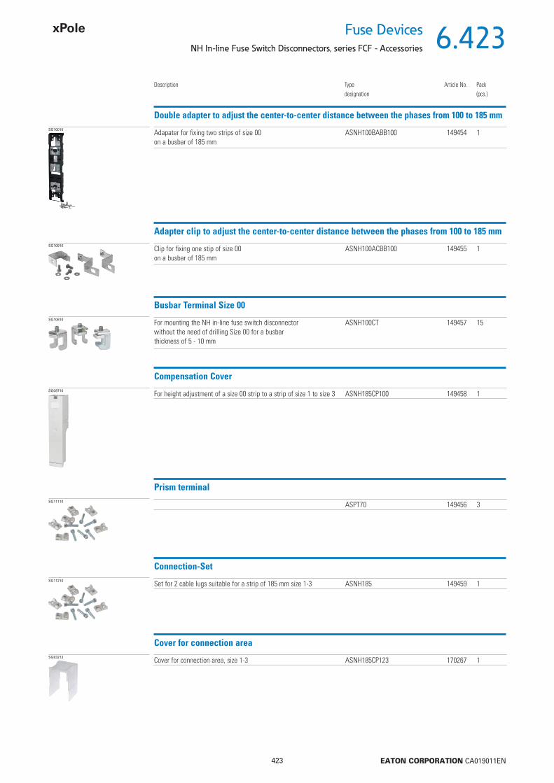
6.423
423 EATON CORPORATION CA019011EN
Fuse DevicesNH In-line Fuse Switch Disconnectors, series FCF - Accessories
Double adapter to adjust the center-to-center distance between the phases from 100 to 185 mmSG10010
Description Typedesignation
Article No. Pack(pcs.)
Adapater for fi xing two strips of size 00on a busbar of 185 mm
ASNH100BABB100 149454 1
Adapter clip to adjust the center-to-center distance between the phases from 100 to 185 mmSG10910 Clip for fi xing one stip of size 00
on a busbar of 185 mmASNH100ACBB100 149455 1
Busbar Terminal Size 00SG10610 For mounting the NH in-line fuse switch disconnector
without the need of drilling Size 00 for a busbarthickness of 5 - 10 mm
ASNH100CT 149457 15
Compensation CoverSG09710 For height adjustment of a size 00 strip to a strip of size 1 to size 3 ASNH185CP100 149458 1
Prism terminalSG11110 ASPT70 149456 3
Connection-SetSG11210 Set for 2 cable lugs suitable for a strip of 185 mm size 1-3 ASNH185 149459 1
Cover for connection areaSG63212 Cover for connection area, size 1-3 ASNH185CP123 170267 1
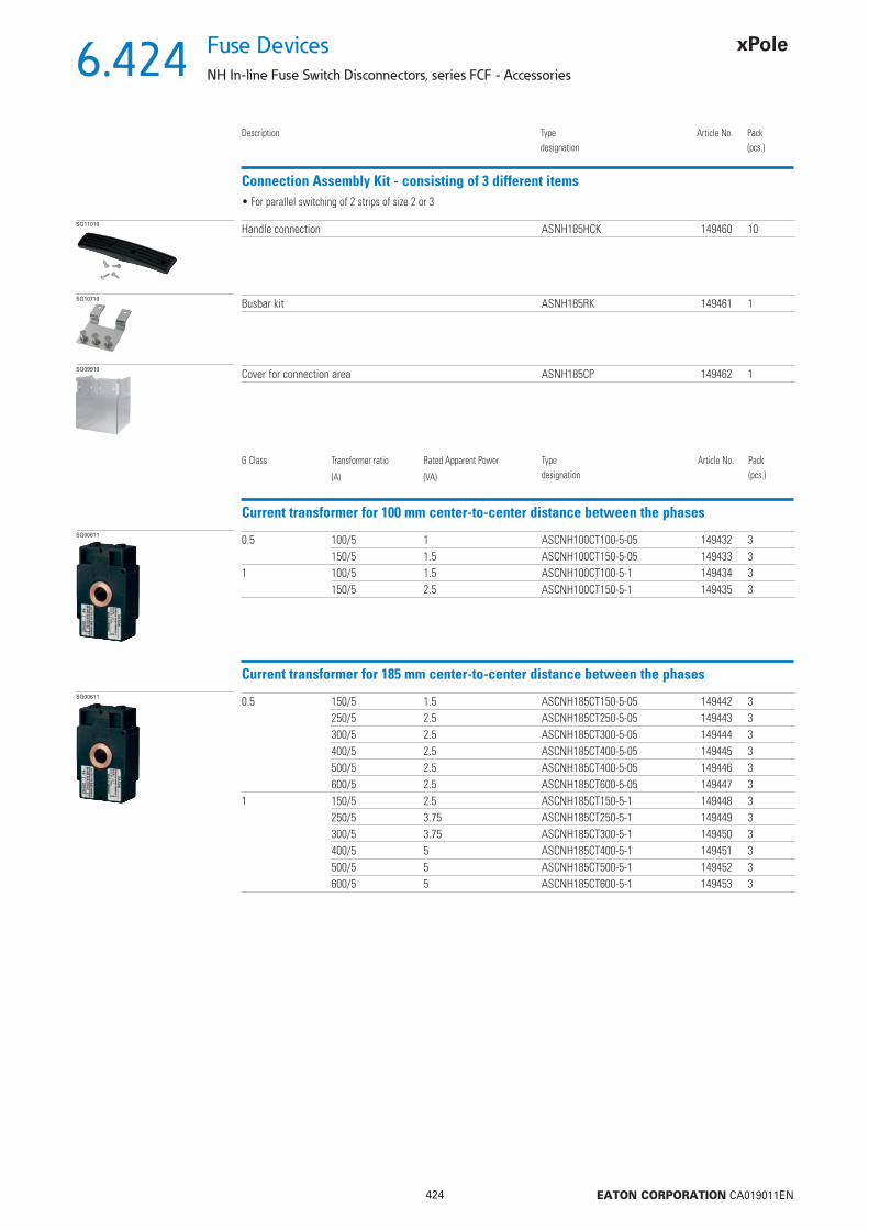
6.424
424 EATON CORPORATION CA019011EN
Fuse Devices
NH In-line Fuse Switch Disconnectors, series FCF - Accessories
Connection Assembly Kit - consisting of 3 different items
SG11010
Description Typedesignation
Article No. Pack(pcs.)
Handle connection ASNH185HCK 149460 10
• For parallel switching of 2 strips of size 2 or 3
SG10710 Busbar kit ASNH185RK 149461 1
SG09910 Cover for connection area ASNH185CP 149462 1
Current transformer for 100 mm center-to-center distance between the phasesSG00611 0.5 100/5 1 ASCNH100CT100-5-05 149432 3
150/5 1.5 ASCNH100CT150-5-05 149433 31 100/5 1.5 ASCNH100CT100-5-1 149434 3
150/5 2.5 ASCNH100CT150-5-1 149435 3
G Class Transformer ratio
(A)
Rated Apparent Power
(VA)
Typedesignation
Article No. Pack(pcs.)
Current transformer for 185 mm center-to-center distance between the phasesSG00611 0.5 150/5 1.5 ASCNH185CT150-5-05 149442 3
250/5 2.5 ASCNH185CT250-5-05 149443 3300/5 2.5 ASCNH185CT300-5-05 149444 3400/5 2.5 ASCNH185CT400-5-05 149445 3500/5 2.5 ASCNH185CT400-5-05 149446 3600/5 2.5 ASCNH185CT600-5-05 149447 3
1 150/5 2.5 ASCNH185CT150-5-1 149448 3250/5 3.75 ASCNH185CT250-5-1 149449 3300/5 3.75 ASCNH185CT300-5-1 149450 3400/5 5 ASCNH185CT400-5-1 149451 3500/5 5 ASCNH185CT500-5-1 149452 3600/5 5 ASCNH185CT600-5-1 149453 3

6.425
425 EATON CORPORATION CA019011EN
Fuse DevicesNH In-line Fuse Switch Disconnectors, series FCF - Technical Data
Technical Data FCFSDNH00BB100(-CTO)
FCFSDNH00BB100(-CTO)ElectricalFor LV HRC fuse-links acc. to DIN VDE 0636-2 Size 000/00Rated operating voltage Ue V AC 690Rated operating current 1) Ie A 160Conv. free air thermal current with fuse-links 1) Ith A 160Conv. free air thermal current with solid-links 1) Ith A 210Rated frequency Hz 40 - 60Rated insulation voltage Ui V AC 800Total power loss at Ith (without fuses) Pv W 18Rated impuls withstand voltage Uimp kV 8Utilization category (AC-22B)
400 V A 160500 V A 160690 V A 100
Conditional rated short-circuit current 2) kA 80Rated short-time withstand current Icw kA –Max. permissible power loss per fuse-link Pa W 12Mechanical Flat connection
Bolt diameter M8Cable lug (DIN 46235) mm2 1 x 10-95 (max. 25 mm width)Flat bar mm 20 x 10Tightening torque Ma Nm 12 - 15
TerminalTerminal capacity mm2 round 1.5 - 70 Cu / fl at 6 x 9 x 0.8Tightening torque Ma Nm 2.6
Degree of protection, front side, device fi ttedOperating condition IP30Switching element open IP10
Ambient temperature 3) Tamb °C -25 up to +55Rated operating mode Permanent operationActivation Dependent manual operationMounting position Vertical, horizontalAltitude m Up to 2000Degree of pollution 3Overvoltage category III
1) In case of mounting several units in low voltage switchgear-combinations , please consider rated diversity factors acc. to EN 60439-1.2) Type-tested with LV-HRC-fuse-links characteristic gG.3) 35 °C normal temperature, at 55 °C with reduced operating current.
• Center-to-center distance of 100 mm between the phases• Size 00

6.426
426 EATON CORPORATION CA019011EN
Fuse Devices
NH In-line Fuse Switch Disconnectors, series FCF - Technical Data
Dimensions (mm)
FCFSDNH00BB100 Outgoers at the top
Outgoers at the bottom
FCFSDNH00BB100-CTOOutgoers at the top
Outgoers at the bottom
Installation of a transformer is possi-
ble at the bottom
Installation of a 3-pole or 1-pole transformer is pos-sible
NH In-line Fuse Switch Disconnectors, 3 poles, center-to-center distance of 100 mm between the phases, size 00
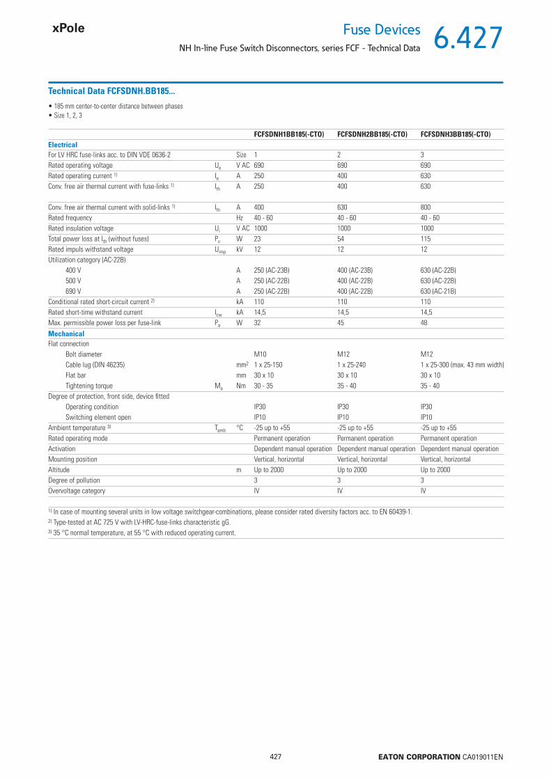
6.427
427 EATON CORPORATION CA019011EN
Fuse DevicesNH In-line Fuse Switch Disconnectors, series FCF - Technical Data
Technical Data FCFSDNH.BB185...
FCFSDNH1BB185(-CTO) FCFSDNH2BB185(-CTO) FCFSDNH3BB185(-CTO)ElectricalFor LV HRC fuse-links acc. to DIN VDE 0636-2 Size 1 2 3Rated operating voltage Ue V AC 690 690 690Rated operating current 1) Ie A 250 400 630Conv. free air thermal current with fuse-links 1) Ith A 250 400 630
Conv. free air thermal current with solid-links 1) Ith A 400 630 800Rated frequency Hz 40 - 60 40 - 60 40 - 60Rated insulation voltage Ui V AC 1000 1000 1000Total power loss at Ith (without fuses) Pv W 23 54 115Rated impuls withstand voltage Uimp kV 12 12 12Utilization category (AC-22B)
400 V A 250 (AC-23B) 400 (AC-23B) 630 (AC-22B)500 V A 250 (AC-22B) 400 (AC-22B) 630 (AC-22B)690 V A 250 (AC-22B) 400 (AC-22B) 630 (AC-21B)
Conditional rated short-circuit current 2) kA 110 110 110Rated short-time withstand current Icw kA 14,5 14,5 14,5Max. permissible power loss per fuse-link Pa W 32 45 48Mechanical Flat connection
Bolt diameter M10 M12 M12Cable lug (DIN 46235) mm2 1 x 25-150 1 x 25-240 1 x 25-300 (max. 43 mm width)Flat bar mm 30 x 10 30 x 10 30 x 10Tightening torque Ma Nm 30 - 35 35 - 40 35 - 40
Degree of protection, front side, device fi ttedOperating condition IP30 IP30 IP30Switching element open IP10 IP10 IP10
Ambient temperature 3) Tamb °C -25 up to +55 -25 up to +55 -25 up to +55Rated operating mode Permanent operation Permanent operation Permanent operationActivation Dependent manual operation Dependent manual operation Dependent manual operationMounting position Vertical, horizontal Vertical, horizontal Vertical, horizontalAltitude m Up to 2000 Up to 2000 Up to 2000Degree of pollution 3 3 3Overvoltage category IV IV IV
1) In case of mounting several units in low voltage switchgear-combinations, please consider rated diversity factors acc. to EN 60439-1.2) Type-tested at AC 725 V with LV-HRC-fuse-links characteristic gG.3) 35 °C normal temperature, at 55 °C with reduced operating current.
• 185 mm center-to-center distance between phases• Size 1, 2, 3

6.428
428 EATON CORPORATION CA019011EN
Fuse Devices
NH In-line Fuse Switch Disconnectors, series FCF - Technical Data
Dimensions (mm)
FCFSDNH1BB185
Connection at the top (Ao)Connection at the bottom (Au)
FCFSDNH2BB185, FCFSDNH3BB185
Connection at the top (Ao)Connection at the bottom (Au)
NH In-line Fuse Switch Disconnectors, 3 poles, center-to-center distance of 185 mm between the phases, size 1 - size 3

6.429
429 EATON CORPORATION CA019011EN
Fuse DevicesNH In-line Fuse Switch Disconnectors, series FCF - Technical Data
Dimensions (mm)
FCFSDNH1BB185-CTO
Connection at the top (Ao)Connection at the bottom (Au)
FCFSDNH2BB185-CTO, FCFSDNH3BB185-CTO
Connection at the top (Ao)Connection at the bottom (Au)
NH In-line Fuse Switch Disconnectors, 3 poles, center-to-center distance of 185 mm between the phases , size 1 - size 3, for installing transformers
Installation of a 3-pole or 1-pole transformer is pos-sible
Installation of a 3-pole or 1-pole transformer is pos-sible
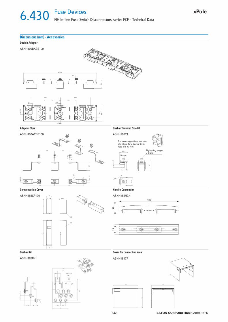
6.430
430 EATON CORPORATION CA019011EN
Fuse Devices
NH In-line Fuse Switch Disconnectors, series FCF - Technical Data
Dimensions (mm) - Accessories
ASNH100BABB100
Double Adapter
ASNH100ACBB100
Adapter Clips
ASNH100CT
Busbar Terminal Size 00
For mounting without the needof drilling, for a busbar thick-ness of 5-10 mm
Tightening torque = 6 Nm
ASNH185CP100
Compensation Cover
ASNH185HCK
Handle Connection
ASNH185RK
Busbar Kit
ASNH185CP
Cover for connection area
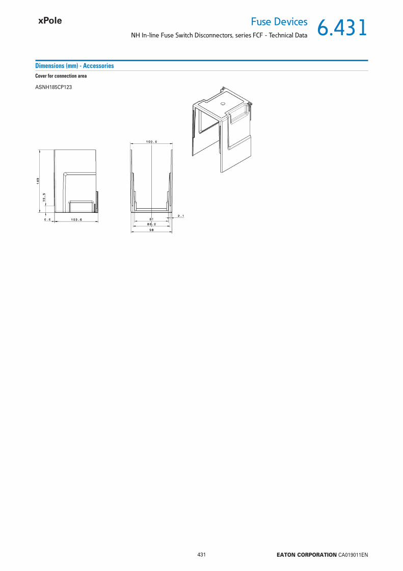
6.431
431 EATON CORPORATION CA019011EN
Fuse DevicesNH In-line Fuse Switch Disconnectors, series FCF - Technical Data
ASNH185CP123
Cover for connection area
Dimensions (mm) - Accessories
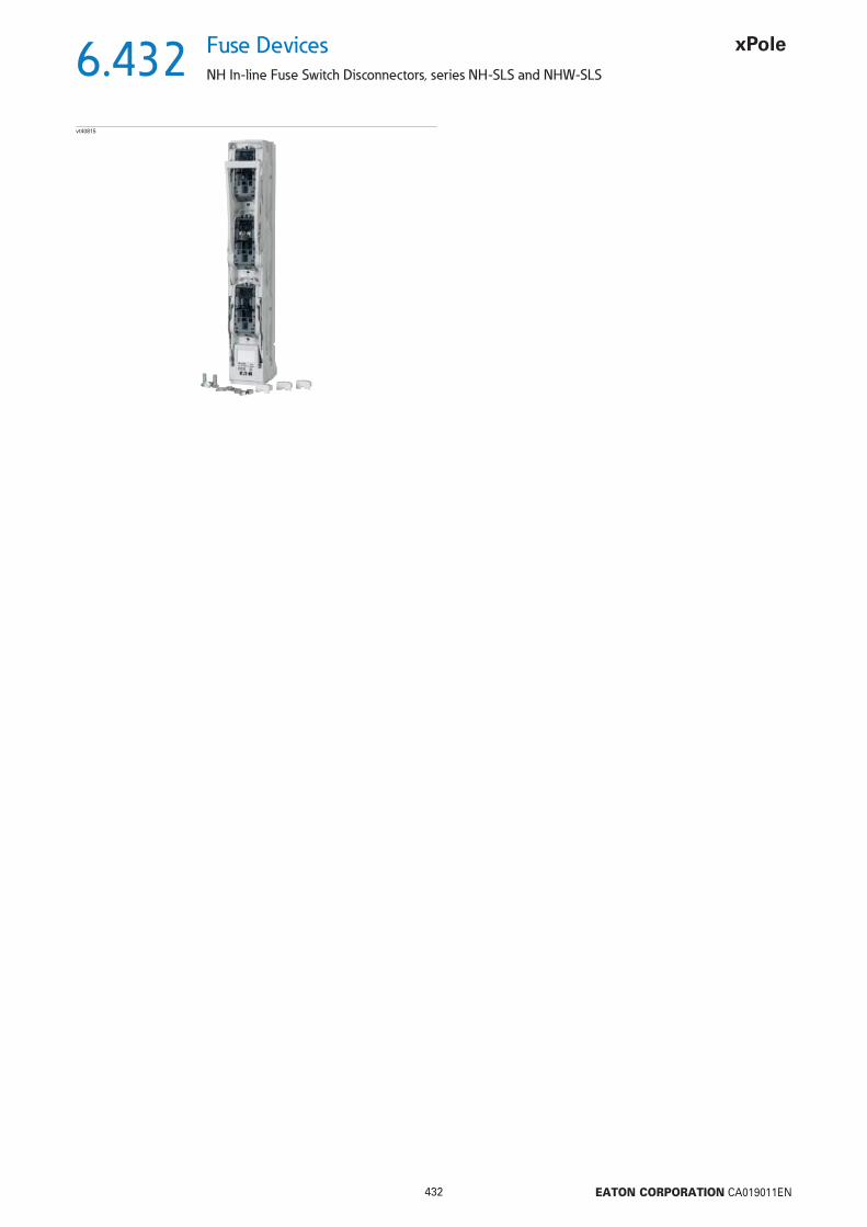
6.432
432 EATON CORPORATION CA019011EN
Fuse Devices
NH In-line Fuse Switch Disconnectors, series NH-SLS and NHW-SLS
vt40815
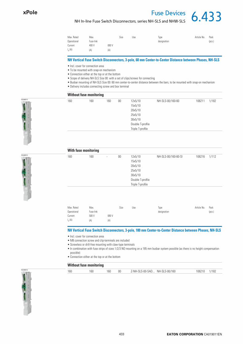
6.433
433 EATON CORPORATION CA019011EN
Fuse DevicesNH In-line Fuse Switch Disconnectors, series NH-SLS and NHW-SLS
NH Vertical Fuse Switch Disconnectors, 3-pole, 60 mm Center-to-Center Distance between Phases, NH-SLS• Incl. cover for connection area• To be mounted with snap-on mechanism• Connection either at the top or at the bottom• Scope of delivery NH-SLS Size 00: with a set of clips/screws for connecting• Busbar mounting of NH-SLS Size 00: 60 mm center-to-center distance between the bars, to be mounted with snap-on mechanism• Delivery includes connecting screw and box terminal
SG46912
Max. RatedOperationalCurrentIe (A)
Max.Fuse-link400 V
(A)
690 V
(A)
Size Use Typedesignation
Article No. Pack(pcs.)
160 160 160 00 12x5/10 NH-SLS-00/160-60 106211 1/18215x5/1020x5/10 25x5/1030x5/10Double T-profi leTriple T-profi le
Without fuse monitoring
SG46912 160 160 - 00 12x5/10 NH-SLS-00/160-60-SI 106216 1/11215x5/1020x5/10 25x5/1030x5/10Double T-profi leTriple T-profi le
With fuse monitoring
NH Vertical Fuse Switch Disconnectors, 3-pole, 100 mm Center-to-Center Distance between Phases, NH-SLS• Incl. cover for connection area• M8 connection screw and clip-terminals are included• Screwless or drill-free mounting with claw-type terminals• In combination with fuse strips of sizes 1/2/3 NO mounting on a 185 mm busbar system possible (as there is no height compensation
possible)• Connection either at the top or at the bottom
SG46912 160 160 160 00 Z-NH-SLS-00-SAD... NH-SLS-00/160 106210 1/182
Without fuse monitoring
Max. RatedOperationalCurrentIe (A)
Max.Fuse-link500 V
(A)
690 V
(A)
Size Use Typedesignation
Article No. Pack(pcs.)

6.434
434 EATON CORPORATION CA019011EN
Fuse Devices
NH In-line Fuse Switch Disconnectors, series NH-SLS and NHW-SLS
NH Vertical Fuse Switch Disconnectors, 3-pole, 185 mm Center-to-Center Distance between Phases, NHW-SLS• With integrated cover for the connection area (additional cover for cable area is possible)• Drill-free mounting using claw-type terminals for size 00 (Z-NHW-SLS-00-BBC, Article No. 179770)• Drill-free mounting using claw-type terminals for sizes 1,2,3 (Z-NHW-SLS-00-BBC, Article No. 179771)• Self-closing test holes integrated in the cover• High version for size 00 = suitable for mounting a current transformer• Flat version for size 00 = NO direct mounting of a current transformer possible, height compensation to construction depth for sizes
1,2,3 via an adapter (NHW-SLS-00-185/185-SADD, Article No. 179764), mounting a current transformer is possible if an adapter is used• Connection either at the top or at the bottom
VT40815 160 160 160 00 high version NHW-SLS-00/H 179754 1160 160 160 00 fl at version NHW-SLS-00/F 179755 1250 250 250 1 NHW-SLS-1 179756 1400 400 400 2 NHW-SLS-2 179757 1630 630 630 3 NHW-SLS-3 179758 1
Without fuse monitoring
Max. RatedOperationalCurrentIe (A)
Max.Fuse-link500 V
(A)
690 V
(A)
Size Notes Typedesignation
Article No. Pack(pcs.)
VT40515 160 160 160 00 high version NHW-SLS-00/H/SI 179759 1160 160 160 00 fl at version NHW-SLS-00/F/SI 179760 1250 250 250 1 NHW-SLS-1/SI 179761 1400 400 400 2 NHW-SLS-2/SI 179762 1630 630 630 3 NHW-SLS-3/SI 179763 1
With fuse monitoring
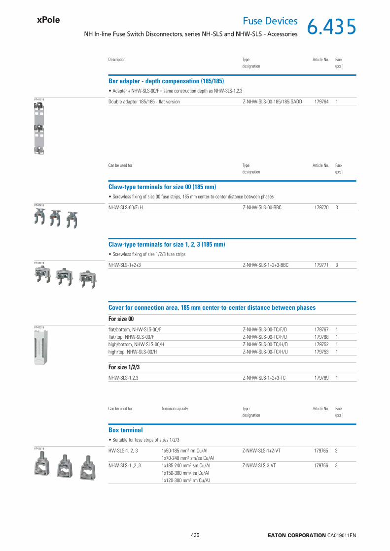
6.435
435 EATON CORPORATION CA019011EN
Fuse DevicesNH In-line Fuse Switch Disconnectors, series NH-SLS and NHW-SLS - Accessories
Bar adapter - depth compensation (185/185)
VT41515
Description Typedesignation
Article No. Pack(pcs.)
Double adapter 185/185 - fl at version Z-NHW-SLS-00-185/185-SADD 179764 1
• Adapter + NHW-SLS-00/F = same construction depth as NHW-SLS-1,2,3
Claw-type terminals for size 00 (185 mm)
VT42415
Can be used for Typedesignation
Article No. Pack(pcs.)
NHW-SLS-00/F+H Z-NHW-SLS-00-BBC 179770 3
• Screwless fi xing of size 00 fuse strips, 185 mm center-to-center distance between phases
Claw-type terminals for size 1, 2, 3 (185 mm)
VT42315 NHW-SLS-1+2+3 Z-NHW-SLS-1+2+3-BBC 179771 3
• Screwless fi xing of size 1/2/3 fuse strips
Cover for connection area, 185 mm center-to-center distance between phases
VT42015 fl at/bottom, NHW-SLS-00/F Z-NHW-SLS-00-TC/F/D 179767 1fl at/top, NHW-SLS-00/F Z-NHW-SLS-00-TC/F/U 179768 1high/bottom, NHW-SLS-00/H Z-NHW-SLS-00-TC/H/D 179752 1high/top, NHW-SLS-00/H Z-NHW-SLS-00-TC/H/U 179753 1
For size 00
NHW-SLS-1,2,3 Z-NHW-SLS-1+2+3-TC 179769 1
For size 1/2/3
Box terminal
VT42615 HW-SLS-1, 2, 3 1x50-185 mm2 rm Cu/Al Z-NHW-SLS-1+2-VT 179765 31x70-240 mm2 sm/se Cu/Al
NHW-SLS-1 ,2 ,3 1x185-240 mm2 sm Cu/Al Z-NHW-SLS-3-VT 179766 31x150-300 mm2 se Cu/Al1x120-300 mm2 rm Cu/Al
• Suitable for fuse strips of sizes 1/2/3
Can be used for Terminal capacity Typedesignation
Article No. Pack(pcs.)

6.436
436 EATON CORPORATION CA019011EN
Fuse Devices
NH In-line Fuse Switch Disconnectors, series NH-SLS and NHW-SLS - Accessories
Quick connector
VT42815
Can be used for Typedesignation
Article No. Pack(pcs.)
Size 00 Z-NHW-00-BK 179773 3
• Suitable for fuse strips of sizes 00, 60 and 100 mm center-to-center distance between phases
Screw (M8) universal
VT42715 Size 00 Z-NHW-SCREW-M8 179772 3
• M8
Connection strap with brace terminal
vt57115
Typedesignation
Article No. Pack(pcs.)
Z-NHW-SPK 182491 1
• Universal use• Direct mounting on Cu rails• Not suitable for fuse strips of the NHW-SLS series• Drill hole for connection screw Ø 13 in the connection strap• For cross sections of 120-300 mm2

6.437
437 EATON CORPORATION CA019011EN
Fuse DevicesNH In-line Fuse Switch Disconnectors, series NH-SLS and NHW-SLS - Technical Data
437 EATON CORPORATION CA008008EN
NH Vertical Fuse Switch Disconnectors, 3-pole, 60 and 100 mm Center-to-Center Distance between Phases, NHW-SLS
Technical Data
Version in accordance with IEC 60947-1: 2007 + A1: 2010, IEC 60947-3: 2008 + A1: 2012Connection at the top and bottomArc quenching deviceFor NH fuse links according to IEC 60269-2-1 size NH00Contact protection even with open switch covers and in parking positionMechanical interlock of fuse linksDegree of protection (front side), Degree of protection in the connection area depends on the installation position
IP30
Connection contacts - Screw M8, clip 2xM5, clear diameter 12 mm- Prismatic terminal connection Cu, Al *) 16-70 mm2 rm, sm, f+AE*) Connections to aluminium conductors are not maintenance-free
For 60 mm center-to-center distance between bars screwless busbar contactingFor 100 mm center-to-center distance between bars - for screw-fi xing on busbars with drill holes, screw M8
- drill-free mounting with clamping bracketVersion 3-pole switchingType of current AC (50-60 Hz)Rated operating voltage 2) Ue V AC 690Rated insulation voltage 2) Ui V 1000Rated impulse withstand voltage without fuse monitoring 2) Uimp kV 8
Rated operating current 1) Ie A 160UUtilization categories without fuse monitoring 2) kV AC22B (690 V)
AC23B (400 V)AC23B (500 V 125 A)
Conditional rated short-circuit current 3) kA 50For NH fuse links according to IEC 60269-2 with power loss per phase up to
W 12
Indicator switch for displaying the cover position2 switches (change-over) can be used
Rated operating voltage V AC 250V DC 30
Rated operating current A AC 5A DC 4
Electronic fuse monitoring2 LED indicatorsMemory functions and remote reset can be programmed2 change-over contacts2x Cu 2.5 mm2 massive, DIN 46288 or 2x Cu1,5 mm2 litz wire with ferrule, DIN 46228-1 /-2 /-3Internal resistance of measurement paths within MOhm range, VDE regulations regarding contact voltage (> 1000 Ohm/V) are complied with.For disconnecting switch off the upstream main switch.
1) For permanent simultaneous operation of several devices please respect the rated load factor acc. to IEC/EN 61439-2, table 101. With AC23B please make sure a distance of 50 mm at the top and 25 mm at the side is guaranteed with regard to grounded components.
2) Fuse monitoring Ue, Ui 400 V AC, Uimp 4 kV, VG2 (mains connections)3) Type-tested with fuse links of operating class gL/gG
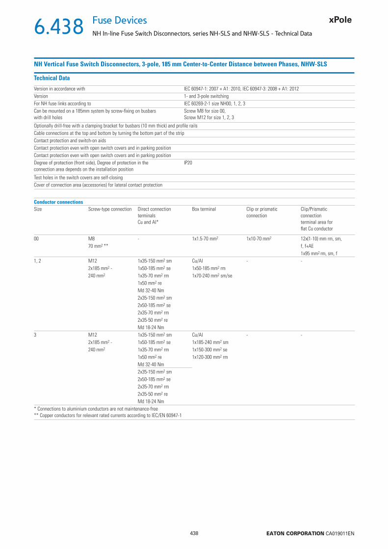
6.438
438 EATON CORPORATION CA019011EN
Fuse Devices
NH In-line Fuse Switch Disconnectors, series NH-SLS and NHW-SLS - Technical Data
NH Vertical Fuse Switch Disconnectors, 3-pole, 185 mm Center-to-Center Distance between Phases, NHW-SLS
Technical Data
Version in accordance with IEC 60947-1: 2007 + A1: 2010, IEC 60947-3: 2008 + A1: 2012Version 1- and 3-pole switchingFor NH fuse links according to IEC 60269-2-1 size NH00, 1, 2, 3Can be mounted on a 185mm system by screw-fi xing on busbars with drill holes
Screw M8 for size 00,Screw M12 for size 1, 2, 3
Optionally drill-free with a clamping bracket for busbars (10 mm thick) and profi le railsCable connections at the top and bottom by turning the bottom part of the stripContact protection and switch-on aidsContact protection even with open switch covers and in parking positionContact protection even with open switch covers and in parking positionDegree of protection (front side), Degree of protection in the connection area depends on the installation position
IP20
Test holes in the switch covers are self-closingCover of connection area (accessories) for lateral contact protection
Conductor connectionsSize Screw-type connection Direct connection
terminalsCu and Al*
Box terminal Clip or prismaticconnection
Clip/Prismaticconnectionterminal area forfl at Cu conductor
00 M8 - 1x1.5-70 mm2 1x10-70 mm2 12x(1-10) mm rm, sm, 70 mm2 ** f, f+AE
1x95 mm2 rm, sm, f1, 2 M12 1x35-150 mm2 sm Cu/Al - -
2x185 mm2 - 1x50-185 mm2 se 1x50-185 mm2 rm240 mm2 1x35-70 mm2 rm 1x70-240 mm2 sm/se
1x50 mm2 reMd 32-40 Nm2x35-150 mm2 sm2x50-185 mm2 se2x35-70 mm2 rm2x35-50 mm2 reMd 18-24 Nm
3 M12 1x35-150 mm2 sm Cu/Al - -2x185 mm2 - 1x50-185 mm2 se 1x185-240 mm2 sm240 mm2 1x35-70 mm2 rm 1x150-300 mm2 se
1x50 mm2 re 1x120-300 mm2 rmMd 32-40 Nm2x35-150 mm2 sm2x50-185 mm2 se2x35-70 mm2 rm2x35-50 mm2 reMd 18-24 Nm
* Connections to aluminium conductors are not maintenance-free** Copper conductors for relevant rated currents according to IEC/EN 60947-1

6.439
439 EATON CORPORATION CA019011EN
Fuse DevicesNH In-line Fuse Switch Disconnectors, series NH-SLS and NHW-SLS - Technical Data
NH Vertical Fuse Switch Disconnectors, 3-pole, 185 mm Center-to-Center Distance between Phases, NHW-SLS
Technical Data (continued)
Size 00 1 2 3Type of current AC (50 Hz) AC (50 Hz) AC (50 Hz) AC (50 Hz)Rated operating voltage 2) Ue V AC 690 690 690 690Rated insulation voltage 2) Ui V 1000 1000 1000 1000Rated impulse withstand voltage without fuse monitoring 2) Uimp KV 8 8 8 8
UUtilization categories without fuse monitoring 2) AC22B AC23B AC23B AC23B(160 A / 500 V) (250 A / 400 V) (400 A / 400 V) (630 A / 400 V)AC23B AC22B AC22B AC22B(160 A / 400 V) (250 A / 690 V) (400 A / 690 V) (630 A / 400 V)
AC21B AC21B AC21B(250 A / 690 V) (400 A / 690 V) (630 A / 400 V)
Conditional rated short-circuit current, 3-pole switching 3) kA 100 / 500 V 80 / 500 V 80 / 500 V 80 / 500 V100 / 690 V 80 / 690 V 80 / 690 V 80 / 690 V
Conditional rated short-circuit current, 1-pole switching 3) kA 100 / 500 V 80 / 500 V 80 / 500 V 80 / 500 V100 / 690 V 80 / 690 V 80 / 690 V 80 / 690 V
For NH fuse links according to IEC 60269-2 4) with power loss per phase up to
W 12 23 34 48
1) For permanent simultaneous operation of several devices please respect the rated load factor acc. to IEC/EN 61439-2, table 101. Please make sure a distance of 50 mm at the top and 25 mm at the side is guaranteed with regard to grounded components.
2) Fuse monitoring Ue, Ui 400 V AC, Uimp 4 kV, VG2 (mains connections)3) Type-tested with fuse links of operating class gL/gG4) NH fuse links of size 1 can be used in NHW-SLS of size 2
Size 3 as double NH vertical fuse disconnector
Technical Data
Size 3 as double NH vertical fuse disconnector 1250 AVersion 3-pole switchingRated operating voltage Ue V AC 690Conditional rated short-circuit current kA up to 80With fuses gL/gGUtilization categories AC20B (690 V)2x630 AIndicator switch for displaying the cover position3 switches (change-over) can be used for sizes 00, 1, 2, 3Rated operating voltage V AC 250
V DC 30Rated operating current A AC 5
A DC 4Electronic fuse monitoring2 LED indicatorsMemory functions and remote reset can be programmed2 change-over contacts2x Cu 2.5 mm2 massive, DIN 46288 or 2x Cu1,5 mm2 litz wire with ferrule, DIN 46228-1 /-2 /-3Internal resistance of measurement paths within MOhm range, VDE regulations regarding contact voltage (> 1000 Ohm/V) are complied with.For disconnecting switch off the upstream main switch.
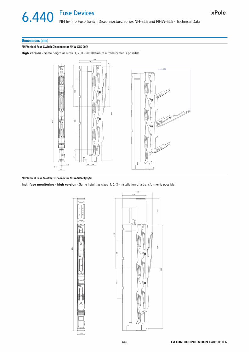
6.440
440 EATON CORPORATION CA019011EN
Fuse Devices
NH In-line Fuse Switch Disconnectors, series NH-SLS and NHW-SLS - Technical Data
Dimensions (mm)
670
5 0
5.5
2.5
285
185
185
1 50
7278
650
3 6 36
37
38
1 89
406max.
High version - Same height as sizes 1, 2, 3 - Installation of a transformer is possible!
NH Vertical Fuse Switch Disconnector NHW-SLS-00/H
50
830
278
167
650
445
185
185
1 50
189
Incl. fuse monitoring - high version - Same height as sizes 1, 2, 3 - Installation of a transformer is possible!
NH Vertical Fuse Switch Disconnector NHW-SLS-00/H/SI

6.441
441 EATON CORPORATION CA019011EN
Fuse DevicesNH In-line Fuse Switch Disconnectors, series NH-SLS and NHW-SLS - Technical Data
Dimensions (mm)
5.52.5
50
670
7
38
37
3 6 36
285
185
185
278
1 47
108
650
16
364max.
Flat version - In order to reach the same depth as with sizes 1, 2, 3 you need to use an additional adapter (NHW-SLS-00-185/185-SADD_179764) - Installation of a transformer is only possible if you use a device adapter
NH Vertical Fuse Switch Disconnector NHW-SLS-00/F
50
830
147
108
278
650
185
185
445
Incl. fuse monitoring - fl at version - In order to reach the same depth as with sizes 1, 2, 3 you need to use an additional adapter (NHW-SLS-00-185/185-SADD_179764) - Installation of a transformer is only possible if you use a device adapter
NH Vertical Fuse Switch Disconnector NHW-SLS-00/F/SI

6.442
442 EATON CORPORATION CA019011EN
Fuse Devices
NH In-line Fuse Switch Disconnectors, series NH-SLS and NHW-SLS - Technical Data
Dimensions (mm)
++
+
+
+
+
max.
3.3B
3.4
M6, 5 - 6 Nm
44 - 53 Ib.in
SW 4
M5, 3 - 4 Nm
27 - 35 Ib.in
SW 4
2
clic
1
++
+
+
+
+
max.
++
+
+
+
+
max.
1,5 - 70 mm²
20
mm
<12
mm
10 - 50 mm²
rm, sm,f, f+AE
70 - 95 mm²
70 mm² rm, sm,f, f+AE
95 mm² rm, sm, f
3.3C
3.3A
M8, 8 - 10 Nm
70 - 90 Ib.in
SW 13
max. Kabelschuh Cable lugs
DIN 46 234 70 mm²
DIN 46 235 70 mm²
Cable connection for size 00 fl at and high version:
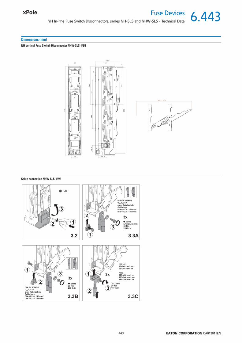
6.443
443 EATON CORPORATION CA019011EN
Fuse DevicesNH In-line Fuse Switch Disconnectors, series NH-SLS and NHW-SLS - Technical Data
Dimensions (mm)
50
670
99
49.5
2
285
185
185
1 50
190
278
650
7
6 2.5
470max.
NH Vertical Fuse Switch Disconnector NHW-SLS-1/2/3
Cable connection NHW-SLS-1/2/3

6.444
444 EATON CORPORATION CA019011EN
Fuse Devices
NH In-line Fuse Switch Disconnectors, series NH-SLS and NHW-SLS - Technical Data
Dimensions (mm)
50
99
185
185
445
167
278
650
1 50
189
63.5
49.5
With fuse monitoring
NH Vertical Fuse Switch Disconnector NHW-SLS-1/2/3-SI
With fuse monitoring
Cable connection NHW-SLS-1/2/3-SI

6.445
445 EATON CORPORATION CA019011EN
Fuse DevicesNH In-line Fuse Switch Disconnectors, series NH-SLS and NHW-SLS - Technical Data
Dimensions (mm) - Accessories
185
185
5 0
83
20
445
1 4.5
42
Z-NHW-SLS-00-185/185-SADD
Double Adapter
29
43.2
2 5
12
22
9
Claw-type terminals for size 00
51.5
36.3
56
30
9.5
14.5
25.5
58.5
37
Claw-type terminals for size 1, 2, 3
W x H x D: 83 x 450 x 50Weight: 55 kg/100

6.446
446 EATON CORPORATION CA019011EN
Fuse Devices
NH-Vertical Fuse-Switch-Disconnector, 3-pole
NH-Vertical Fuse-Switch-Disconnector, 3-pole
wa_sg02212 160 160 100 00 20 x 1025 x 1030 x 10
Connection at the top or bottom. Clamp strap 4-70 mm² or screw M8.
LTS-L/160/00-60-10-R 289997 1/100
RatedOperational Current Ie (A)
Max.Fuse-link500V(A)
690V(A)
Size Utilisation Notes TypeDesignation
Article No. Units perpackage
• Incl. terminal cover• Drill-free mounting • Clamp straps included in the delivery
Compensation covers for combination with NH-fuse-switch-disconnectors LTS
Terminal Capacity Utilisation Notes TypeDesignation
Article No. Units perpackage
Accessories for NH-Vertical Fuse-Switch-Disconnector
70
Cover level to Cu-front distance: 70 mm
LTS-L/160/00-60-10-R Z-LTS-L/160-AB/70-SET 289995 1 set
Cover level to Cu-front distance: 90 mm
LTS-L/160/00-60-10-R Z-LTS-L/160-AB/90-SET 289996 1 set
90
Lateral cover for LTS, LTS-L
SG16005 In connection with the compensation covers they serve as support for the front plate, as well as electric shock protection
LTS-L... LTS...
Z-LTS-SAB/70-90 288908 2
Clamp Straps
wa_sg02312 4-70 mm² Cu LTS-L/160/00-60-10-R 3 Clamp Straps per device
Z-LTS-160-BK 286812 3/180
Screws
Wa_sg02702 M86-70 mm² Cu16-95 mm² Al
LTS-L/160/00-60-10-R 3 screwsper device
Z-LTS-SC 263119 3/180
For NH-fuse-links Z-NH/00... and solid-links Z-NH-...TR see chapter Accessories Fuse Devices.

6.447
447 EATON CORPORATION CA019011EN
Fuse DevicesNH-Vertical Fuse-Switch-Disconnector, 3-pole
NH-Vertical Fuse-Switch-Disconnector, 3-pole
wa_sg02212 160 160 100 00 Z-LTS-L./00-SAD. Connection at the top or bottom. Clamp strap 4-70 mm² or screw M8.
LTS-L/160/00 269349 1/100
RatedOperational Current Ie (A)
Max.Fuse-link500V(A)
690V(A)
Size Utilisation Notes TypeDesignation
Article No. Units perpackage
• Incl. terminal cover• Drill-free mounting thanks to terminal clamps• Scope of delivery LTS-L/160/00: incl. terminal clamps and clamp straps LTS-L/160/00/3-L: type with lift terminals 70 mm2 and terminal clamps LTL-L sizes 1, 2, 3: no terminal clamps included, no clamp straps included• Busbar mounting Size 00: LTS-L/160/00... distance 100 mm, drill-free mounting / optional screw-mounting Sizes 1, 2, 3: distance 185 mm, screw-mounting / optional drill-free mounting
Adapters
Terminal Capacity Utilisation Notes TypeDesignation
Article No. Units perpackage
Accessories for NH-Vertical Fuse-Switch-Disconnector
Single adapter 100/185 LTS-L/160/00... Cu...x5/10 Z-LTS-LG/00-SAD 263118 1Double adapter 100/185 LTS-L/160/00... Cu...x5/10 Z-LTS-L/160-SADD 286815 1
Adapter for drill-free mounting
wa_sg01202
SG57312 250 250 200 1 screwed30 x 5/1040 x 5/1050 x 5/1060 x 5/1080 x 5/10
Connection at the top or bottom. Screw M10
LTS-L/250/1 269350 1/33
400 400 315 2 Screw M12 LTS-L/400/2 269351 1/33630 630 500 3 terminal clamps
30 x 5/1040 x 5/1050 x 5/1060 x 5/1080 x 5/10
Screw M12 LTS-L/630/3 269352 1/33
Single adapter 100/185 LTS-L/160/00... Cu...x5/10 Z-LTS-L/160-SAD-KR 263114 1Double adapter 100/185 LTS-L/160/00... Cu...x5/10 Z-LTS-L/160-SADD-KR 286816 1
For NH-fuse-links Z-NH/00... and solid-links Z-NH-...TR see chapter Accessories Fuse Devices.

448 EATON CORPORATION CA019011EN
7.448Measuring Instruments
Measuring Devices
wa_sg05811 wa_sg04911

449 EATON CORPORATION CA019011EN
7.449Measuring InstrumentsPower Meter EME
Power Meter EME
System Rated current TypeDesignation
Article No. Units perpackage
SG10007 1N 32 A EME1P32 167397 11N 32 A, MID cert. EME1P32MID 167398 13N 80 A EME3P80 167413 13N 80 A, MID cert. EME3P80MID 167414 13N 5 A, CT EME3PCT 167417 13N 125 A, MID cert. EME3P125MID 167416 1
Accessories Current Transformer
Z-MG/WAK: maximum cable diameter 21 mmZ-MG/WAS: maximum busbar cross section 30 x 10 mm, 40 x 10 mm or 50 x 12 mm, cable diameter 23 mm / 30 mm
- according to type, see dimension diagramms
Communication moduless
Description TypeDesignation
Article No. Units perpackage
wa_sg00312 Communication module MBUS EMECMBUS 167420 1Communication module with MODBUS EMECMODB 167421 1
EMECMODB
Basic Devices
System Rated current TypeDesignation
Article No. Units perpackage
wa_sg05711 3N 63 A, MODBUS EME3P63BMODBUS 167409 1PHASE OUT
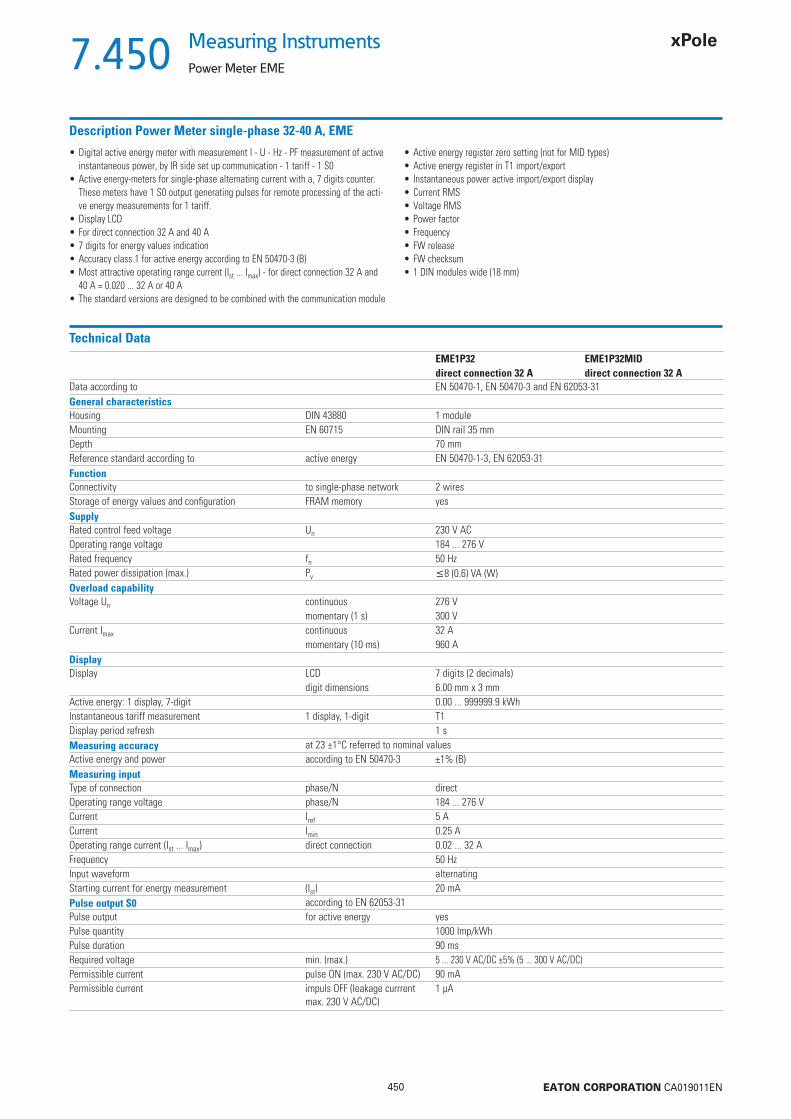
450 EATON CORPORATION CA019011EN
7.450Measuring Instruments
Power Meter EME
Description Power Meter single-phase 32-40 A, EME
• Digital active energy meter with measurement I - U - Hz - PF measurement of active instantaneous power, by IR side set up communication - 1 tariff - 1 S0
• Active energy-meters for single-phase alternating current with a, 7 digits counter. These meters have 1 S0 output generating pulses for remote processing of the acti-ve energy measurements for 1 tariff.
• Display LCD• For direct connection 32 A and 40 A• 7 digits for energy values indication• Accuracy class 1 for active energy according to EN 50470-3 (B)• Most attractive operating range current (Ist ... Imax) - for direct connection 32 A and
40 A = 0.020 ... 32 A or 40 A• The standard versions are designed to be combined with the communication module
• Active energy register zero setting (not for MID types)• Active energy register in T1 import/export• Instantaneous power active import/export display• Current RMS• Voltage RMS• Power factor• Frequency• FW release• FW checksum• 1 DIN modules wide (18 mm)
Technical DataEME1P32 EME1P32MIDdirect connection 32 A direct connection 32 A
Data according to EN 50470-1, EN 50470-3 and EN 62053-31General characteristicsHousing DIN 43880 1 moduleMounting EN 60715 DIN rail 35 mmDepth 70 mmReference standard according to active energy EN 50470-1-3, EN 62053-31FunctionConnectivity to single-phase network 2 wiresStorage of energy values and confi guration FRAM memory yesSupplyRated control feed voltage Un 230 V ACOperating range voltage 184 ... 276 VRated frequency fn 50 HzRated power dissipation (max.) Pv 8 (0.6) VA (W)Overload capabilityVoltage Un continuous 276 V
momentary (1 s) 300 VCurrent Imax continuous 32 A
momentary (10 ms) 960 ADisplayDisplay LCD 7 digits (2 decimals)
digit dimensions 6.00 mm x 3 mmActive energy: 1 display, 7-digit 0.00 ... 999999.9 kWhInstantaneous tariff measurement 1 display, 1-digit T1Display period refresh 1 sMeasuring accuracy at 23 ±1°C referred to nominal valuesActive energy and power according to EN 50470-3 ±1% (B)Measuring inputType of connection phase/N directOperating range voltage phase/N 184 ... 276 VCurrent Iref 5 ACurrent Imin 0.25 AOperating range current (Ist ... Imax) direct connection 0.02 ... 32 AFrequency 50 HzInput waveform alternatingStarting current for energy measurement (Ist) 20 mAPulse output S0 according to EN 62053-31Pulse output for active energy yesPulse quantity 1000 Imp/kWhPulse duration 90 msRequired voltage min. (max.) 5 ... 230 V AC/DC ±5% (5 ... 300 V AC/DC)Permissible current pulse ON (max. 230 V AC/DC) 90 mAPermissible current impuls OFF (leakage currrent
max. 230 V AC/DC)1 μA

451 EATON CORPORATION CA019011EN
7.451Measuring InstrumentsPower Meter EME
Technical Data (continue page)EME1P32 EME1P32MIDdirect connection 32 A direct connection 32 A
Optical interfacesFront side (accuracy control) LED 5000 Imp/kWhSafety according to EN 50470-1Indoor meter yesPollution degree 2Rated operational voltage 300 VAC voltage test EN 50470-3. 7.2 4 kVTest voltage 1.2/50 μs 6 kVProtection class EN 50470 IIHousing material fl ame resistance UL 94 V0Safety-sealing between upper and lower housing part no yesAdaptor for CommunicationPlug-and-play technology yesLAN Interface (TCP/IP) Ethernet 802.3 10/100 Mbps EMECLANModbus RTU, Ascii Interface RS-485 3 wires up to 19,200 bps EMECMODBM-Bus Interface RS-485 2 wires up to 9,600 bps EMECMBUSConnection terminalsType cage main current paths screw head Z +/- PZ1 POZIDRIVType cage pulse output blade for slotted screw 0.8 x 3.5 mmTerminal capacity main current paths solid min. (max.) 16 mm2
stranded wire with sleeve min. (max.) 16 mm2
Terminal capacity pulse outlet solid min. (max.) 0.15 (2.5) mm2
stranded wire with sleeve min. (max.) 0.15 (4) mm2
Environmental conditionsMechanical environment M1Electromagnetic environment E2Operative temperature -10 to +55 °CLimit temperature of transportation and storage -25 to +70 °CVibrations sinusoidal vibration amplitude at 50 Hz ±0.075 mmDegree protectionhousing when mounted in front (terminal) IP51*)/IP20
*) For the installation in a cabinet at least with IP51 protection
Dimensions (mm) Connection diagram
A Miniature Circuit Breaker of 32A or 40A is recommended.
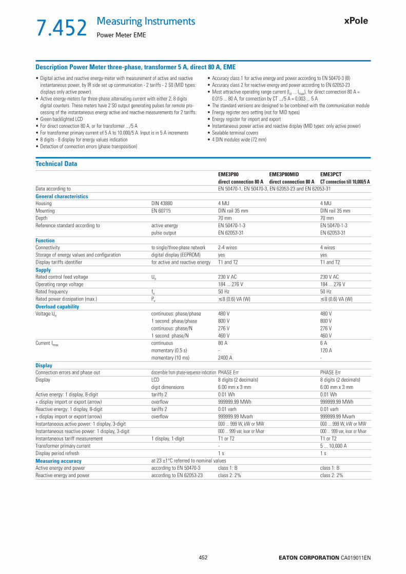
452 EATON CORPORATION CA019011EN
7.452Measuring Instruments
Power Meter EME
Description Power Meter three-phase, transformer 5 A, direct 80 A, EME
• Digital active and reactive energy-meter with measurement of active and reactive instantaneous power, by IR side set up communication - 2 tariffs - 2 S0 (MID types: displays only active power).
• Active energy-meters for three-phase alternating current with either 2, 8 digits digital counters. These meters have 2 S0 output generating pulses for remote pro-cessing of the instantaneous energy active and reactive measurements for 2 tariffs.
• Green backlighted LCD• For direct connection 80 A, or for transformer .../5 A• For transformer primary current of 5 A to 10.000/5 A. Input is in 5 A increments• 8 digits - 8 display for energy values indication• Detection of connection errors (phase transposition)
• Accuracy class 1 for active energy and power according to EN 50470-3 (B)• Accuracy class 2 for reactive energy and power according to EN 62053-23• Most attractive operating range current (Ist ... Imax), for direct connection 80 A =
0.015 ... 80 A, for connection by CT .../5 A = 0.003 ... 5 A• The standard versions are designed to be combined with the communication module• Energy register zero setting (not for MID types)• Energy register for import and export• Instantaneous power active and reactive display (MID types: only active power)• Sealable terminal covers• 4 DIN modules wide (72 mm)
Technical DataEME3P80 EME3P80MID EME3PCTdirect connection 80 A direct connection 80 A CT connection till 10,000/5 A
Data according to EN 50470-1, EN 50470-3, EN 62053-23 and EN 62053-31General characteristicsHousing DIN 43880 4 MU 4 MUMounting EN 60715 DIN rail 35 mm DIN rail 35 mmDepth 70 mm 70 mmReference standard according to active energy EN 50470-1-3 EN 50470-1-3
pulse output EN 62053-31 EN 62053-31FunctionConnectivity to single/three-phase network 2-4 wires 4 wiresStorage of energy values and confi guration digital display (EEPROM) yes yesDisplay tariffs identifi er for active and reactive energy T1 and T2 T1 and T2SupplyRated control feed voltage Un 230 V AC 230 V ACOperating range voltage 184 ... 276 V 184 ... 276 VRated frequency fn 50 Hz 50 HzRated power dissipation (max.) Pv 8 (0.6) VA (W) 8 (0.6) VA (W)Overload capabilityVoltage Un continuous: phase/phase 480 V 480 V
1 second: phase/phase 800 V 800 Vcontinuous: phase/N 276 V 276 V1 second: phase/N 460 V 460 V
Current Imax continuous 80 A 6 Amomentary (0.5 s) - 120 Amomentary (10 ms) 2400 A -
DisplayConnection errors and phase out discernible from phase-sequence indication PHASE Err PHASE ErrDisplay LCD 8 digits (2 decimals) 8 digits (2 decimals)
digit dimensions 6.00 mm x 3 mm 6.00 mm x 3 mmActive energy: 1 display, 8-digit tariffs 2 0.01 Wh 0.01 Wh+ display import or export (arrow) overfl ow 999999.99 MWh 999999.99 MWhReactive energy: 1 display, 8-digit tariffs 2 0.01 varh 0.01 varh+ display import or export (arrow) overfl ow 999999.99 Mvarh 999999.99 MvarhInstantaneous active power: 1 display, 3-digit 000 ... 999 W, kW or MW 000 ... 999 W, kW or MWInstantaneous reactive power: 1 display, 3-digit 000 ... 999 var, kvar or Mvar 000 ... 999 var, kvar or MvarInstantaneous tariff measurement 1 display, 1-digit T1 or T2 T1 or T2Transformer primary current - 5 ... 10,000 ADisplay period refresh 1 s 1 sMeasuring accuracy at 23 ±1°C referred to nominal valuesActive energy and power according to EN 50470-3 class 1: B class 1: BReactive energy and power according to EN 62053-23 class 2: 2% class 2: 2%

453 EATON CORPORATION CA019011EN
7.453Measuring InstrumentsPower Meter EME
Technical Data (continue page)EME3P80 EME3P80MID EME3PCTdirect connection 80 A direct connection 80 A CT connection till 10,000/5 A
Measuring inputType of connection direct transformer .../5 AVoltage Un phase/phase 400 V 400 V
phase/N 230 V 230 VOperating range voltage phase/phase 319 ... 480 V 319 ... 480 V
phase/N 184 ... 276 V 184 ... 276 VCurrent Iref 5 A -Current In - 5 ACurrent Imin 0.25 A 0.05 AOperating range current (Ist ... Imax) direct connection 0.015 ... 80 A -
transformer connection (CT) - 0.003 ... 6 ATransformer current primary current of the transformer - 5 ...10,000 A
smallest input step adjustment - in 5 A stepsFrequency 50 Hz 50 HzInput waveform sinusoidal sinusoidalStarting current for energy measurement (Ist) 15 mA 3 mAPulse output S0 according to EN 62053-31Pulse output for active and reactive energy T1 and T2 yes yesPulse quantity at direct connection 80 A 500 Imp/kWh -
depending on the transformer factor - 100-10-1 Imp/kWhPulse duration 30 ms ±2 30 ms ±2Required voltage min. (max.) 5 ... 230 V AC/DC ±5% (5 ... 300 V AC/DC) 5 ... 230 V AC/DC ±5% (5 ... 300 V AC/DC)Permissible current pulse ON (max. 230 V AC/DC) 90 mA 90 mAPermissible current impuls OFF (leakage currrent max. 230 V AC/DC) 1 μA 1 μAOptical interfacesFront side (accuracy control) LED 1000 Imp/kWh 10000 Imp/kWhSafety according to EN 50470-1Indoor meter yes yesPollution degree 2 2Rated operational voltage 300 V 300 VAC voltage test EN 50470-3. 7.2 4 kV 4 kVTest voltage 1.2/50 μs 6 kV 6 kVProtection class EN 50470 II IIHousing material fl ame resistance UL 94 V0 V0Safety-sealing between upper and lower housing part yes no noAdaptor for CommunicationPlug-and-play technology yes yesLAN Interface (TCP/IP) Ethernet 802.3 10/100 Mbps EMECLAN 10/100 Mbps EMECLANModbus RTU, Ascii Interface RS-485 3 wires up to 19,200 bps EMECMODB up to 19,200 bps EMECMODBM-Bus Interface RS-485 2 wires up to 9,600 bps EMECMBUS up to 9,600 bps EMECMBUSConnection terminalsType cage main current paths screw head Z +/- PZ2 POZIDRIV PZ1 POZIDRIVType cage pulse output blade for slotted screw 0.8 x 3.5 mm 0.8 x 3.5 mmTerminal capacity main current paths solid min. (max.) 1.5 (35) mm2 1 (4) mm2
stranded wire with sleeve min. (max.) 1.5 (35) mm2 1 (4) mm2
Terminal capacity pulse outlet solid min. (max.) 1 (4) mm2 1 (4) mm2
stranded wire with sleeve min. (max.) 1 (2.5) mm2 1 (4) mm2
Environmental conditionsMechanical environment M1 M1Electromagnetic environment E2 E2Operative temperature -10 to +55 °C -10 to +55 °CLimit temperature of transportation and storage -25 to +70 °C -25 to +70 °CRelative humidity (not condensation) 80% 80%Vibrations sinusoidal vibration amplitude at 50 Hz ±0.075 mm ±0.075 mmDegree protectionhousing when mounted in front (terminal)
IP51*)/IP20 IP51*)/IP20
*) For the installation in a cabinet at least with IP51 protection

454 EATON CORPORATION CA019011EN
7.454Measuring Instruments
Power Meter EME
Dimensions (mm) Connection diagram
A Miniature Circuit Breaker of 80A is recommended.
Wire N needs to be connected to the meter.
Direct connection to 80 A

455 EATON CORPORATION CA019011EN
7.455Measuring InstrumentsPower Meter EME
Dimensions (mm) Connection diagram
Wire N needs to be connected to the meter.
Instructions for the connection of transformer countersA Miniature Circuit Breaker of 6A is recommended. Current transformers must not be operated with open terminals since dangerous high voltages might occur which may result in personal injuries and property damage. In addition to this, the transformers are exposed to thermal overload.
Connection through CT .../5 A to 10,000/5 A

456 EATON CORPORATION CA019011EN
7.456Measuring Instruments
Power Meter EME
Description Power Meter three-phase 125 A, EME
• Digital active and reactive energy-meter with measurement of active and reactive instantaneous power, by IR side set up communication - 2 tariffs - 2 S0 (MID types: displays only active power).
• Active energy-meters for three-phase alternating current with either 2, 8 digits digital counters. These meters have 2 S0 output generating pulses for remote pro-cessing of the instantaneous energy active and reactive measurements for 2 tariffs.
• Green backlighted LCD• For direct connection 125 A• 8 digits - 8 display for energy values indication• Detection of connection errors (phase transposition)• Accuracy class 1 for active energy and power according to EN 50470-3 (B)
• Accuracy class 2 for reactive energy and power according to EN 62053-23• Most attractive operating range current (Ist ... Imax) for direct connection 125 A =
0.020 ... 125 A• The standard versions are designed to be combined with the communication module• Energy register zero setting (not for MID types)• Energy register for import and export• Instantaneous power active and reactive display (MID types: only active power)• Sealable terminal covers• 6 DIN modules wide (108 mm)
Technical DataEME3P125MIDdirect connection 125 A
Data according to EN 50470-1, EN 50470-3, EN 62053-23 and EN 62053-31General characteristicsHousing DIN 43880 6 MUMounting EN 60715 DIN rail 35 mmDepth 70 mmReference standard according to active energy EN 50470-1-3
reactive energy - pulse output EN 62053-23-31FunctionConnectivity to single/three-phase network 2-4 wiresStorage of energy values and confi guration digital display (EEPROM) yesDisplay tariffs identifi er for active and reactive energy T1 and T2SupplyRated control feed voltage Un 230 V ACOperating range voltage 184 ... 276 VRated frequency fn 50 HzRated power dissipation (max.) Pv 8 (0.6) VA (W)Overload capabilityVoltage Un continuous: phase/phase 480 V
1 second: phase/phase 800 Vcontinuous: phase/N 276 V1 second: phase/N 300 V
Current Imax continuous 125 Amomentary (10 ms) 3750 A
DisplayConnection errors and phase out discernible from phase-sequence indication PHASE ErrDisplay LCD 8 digits (2 decimals)
digit dimensions 6.00 mm x 3 mmActive energy: 1 display, 8-digit tariffs 2 0.01 Wh+ display import or export (arrow) overfl ow 999999.99 MWhReactive energy: 1 display, 8-digit tariffs 2 0.01 varh+ display import or export (arrow) overfl ow 999999.99 MvarhInstantaneous active power: 1 display, 3-digit 000 ... 999 W, kW or MWInstantaneous reactive power: 1 display, 3-digit 000 ... 999 var, kvar or MvarInstantaneous tariff measurement 1 display, 1-digit T1 or T2Display period refresh 1 sMeasuring accuracy at 23 ±1°C referred to nominal valuesActive energy and power according to EN 50470-3 class 1: BReactive energy and power according to EN 62053-23 class 2: 2%

457 EATON CORPORATION CA019011EN
7.457Measuring InstrumentsPower Meter EME
Technical Data (continue page)EME3P125MIDdirect connection 125 A
Measuring inputType of connection directVoltage Un phase/phase 400 V
phase/N 230 VOperating range voltage phase/phase 319 ... 480 V
phase/N 184 ... 276 VCurrent Iref 5 ACurrent Imin 0.25 AOperating range current (Ist ... Imax) direct connection 0.020 ... 125 AFrequency 50 Hz ±2%Input waveform sinusoidalStarting current for energy measurement (Ist) 20 mAPulse output S0 according to EN 62053-31Pulse output for active and reactive energy T1 and T2 yesPulse quantity at direct connection 80 A 500 Imp/kWhPulse duration 30 ms ±2Required voltage min. (max.) 5 ... 230 V AC/DC ±5% (5 ... 300 V AC/DC)Permissible current pulse ON (max. 230 V AC/DC) 90 mAPermissible current impuls OFF (leakage currrent max. 230 V AC/DC) 1 μAOptical interfacesFront side (accuracy control) LED 1000 Imp/kWhSafety according to EN 50470-1Indoor meter yesPollution degree 2Rated operational voltage 300 VAC voltage test EN 50470-3. 7.2 4 kVTest voltage 1.2/50 μs 6 kVProtection class EN 50470 IIHousing material fl ame resistance UL 94 V0Safety-sealing between upper and lower housing part yesAdaptor for CommunicationPlug-and-play technology yesLAN Interface (TCP/IP) Ethernet 802.3 10/100 Mbps EMECLANModbus RTU, Ascii Interface RS-485 3 wires up to 19,200 bps EMECMODBM-Bus Interface RS-485 2 wires up to 9,600 bps EMECMBUSConnection terminalsType cage main current paths screw head Z +/- PZ2 POZIDRIVType cage pulse output blade for slotted screw 0.8 x 3.5 mmTerminal capacity main current paths solid min. (max.) 1.5 (50) mm2
stranded wire with sleeve min. (max.) 1.5 (50) mm2
Terminal capacity pulse outlet solid min. (max.) 1 (4) mm2
stranded wire with sleeve min. (max.) 1 (2.5) mm2
Environmental conditionsMechanical environment M1Electromagnetic environment E2Operative temperature -10 to +55 °CLimit temperature of transportation and storage -25 to +70 °CRelative humidity (not condensation) 80%Vibrations sinusoidal vibration amplitude at 50 Hz ±0.075 mmDegree protectionhousing when mounted in front (terminal) IP51*)/IP20
*) For the installation in a cabinet at least with IP51 protection
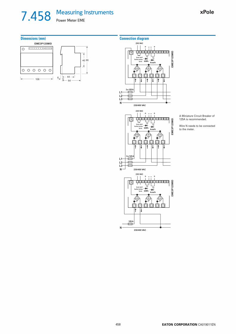
458 EATON CORPORATION CA019011EN
7.458Measuring Instruments
Power Meter EME
Dimensions (mm) Connection diagram
A Miniature Circuit Breaker of 125A is recommended.
Wire N needs to be connected to the meter.

459 EATON CORPORATION CA019011EN
7.459Measuring InstrumentsPower Meter EME
Description M-Bus interface EMECMBUS
• Additional communication modules for Energy-meter, Network analyzer and Power-meters
• Additional module for M-Bus connection for energy, power, V, I, cosj, frequency
• M-Bus according to EN1434• Suitable for both single-phase and three-phase energy meters• 1 DIN module wide (18 mm)
Technical DataEMECMBUS
Data according to EN 13757-1-2-3, IEC 60950, EN 61000-6-2, EN 61000-6-3 and EN 61000-4-2General characteristicsHousing DIN 43880 1 moduleMounting EN 60715 DIN rail 35 mmDepth 70 mmPower supplyPower supply through bus connectionFunctionSuitable for both single-phase and three-phase energy meters yesModbus interfaceHW Interface 2 lift terminalsSW protocol M-Bus according to EN1434Baudrate 300-9600 baudInterface to measuring instrumentHW Interface optical IR 2 (Tx, Rx)SW protocol proprietarySafety according to IEC 60950Pollution degree 2Overvoltage category IIRated operational voltage 24 ... 36 VAir gap in equipment 1.5 mm
on PCB (not coated) 1.5 mmMinimum creepage distance 2.1 mmTest voltage impulse (1.2/50 μs) 2.5 kV
50 Hz 1 min 1.35 kVHousing material fl ame resistance UL 94 V0Connection terminalsType cage main current paths screw head Z +/- PZ0 POZIDRIVTerminal capacity solid min. (max.) 0.15 (2.5) mm2
stranded wire with sleeve min. (max.) 0.15 (4) mm2
Environmental conditionsOperative temperature 0 to +55 °CLimit temperature of transportation and storage -25 to +70 °CRelative humidity (not condensation) 80%Vibrations sinusoidal vibration amplitude at 50 Hz ±0.25 mmProtection class acc. to IEC 60950 IIDegree of protection, housing when mounted in front IP20
Dimensions (mm)

460 EATON CORPORATION CA019011EN
7.460Measuring Instruments
Power Meter EME
Description Modbus Interface RTU and Ascii EMECMODB
• Additional communication modules for Energy-meter, Network analyzer and Power-meters
• Additional module for Modbus RTU and Ascii connection for energy, power, V, I, cosj, frequency
• Protocols Modbus Ascii - Modbus RTU• Suitable for both single-phase and three-phase energy meters• 1 DIN module wide (18 mm)
Technical DataEMECMODB
Data according to IEC 60950, EN 61000-6-2, EN 61000-6-3 and EN 61000-4-2General characteristicsHousing DIN 43880 1 moduleMounting EN 60715 DIN rail 35 mmDepth 70 mmSupplyRated control feed voltage Un 230 V ACAuxiliary power rating 10 WAuxiliary voltage range 0.80 ... 1.20 V AC x Un
Rated frequency 50/60 HzFrequency range 45 ... 65 HzFunctionProtocol selectable by software Modbus RTU or AsciiSuitable for both single-phase and three-phase energy meters yesModbus interfaceHW Interface RS-485 3 terminals (+/-, cable shielded)Input resistance 1 UL (12 k)Termination resistance 80 SW protocol selectable by software Modbus Ascii - Modbus RTUData transfer speed selectable by software 38,400 baud - default: 19,200 baudParity none/even - default: noneAddressing 1 to 247Interface to measuring instrumentHW Interface optical IR 2 (Tx, Rx)SW protocol proprietarySafety according to IEC 60950Pollution degree 2Overvoltage category IIRated operational voltage 300 VAir gap 4 mmMinimum creepage distance 4 mmTest voltage impulse (1.2/50 μs) with AC-Supply 2.5 kV
impulse (1.2/50 μs) telecommunication network 1.5 kV50 Hz 1 min 2.5 kV
Housing material fl ame resistance UL 94 V0Connection terminalslift terminals screw head Z +/- PZ0 POZIDRIVTerminal capacity solid min. (max.) 0.15 (2.5) mm2
stranded wire with sleeve min. (max.) 0.15 (4) mm2
Environmental conditionsOperative temperature 0 to +55 °CLimit temperature of transportation and storage -25 to +70 °CRelative humidity (not condensation) 80%Vibrations sinusoidal vibration amplitude at 50 Hz ±0.25 mmProtection class acc. to IEC 60950 IIDegree of protection, housing when mounted in front IP20
Dimensions (mm)
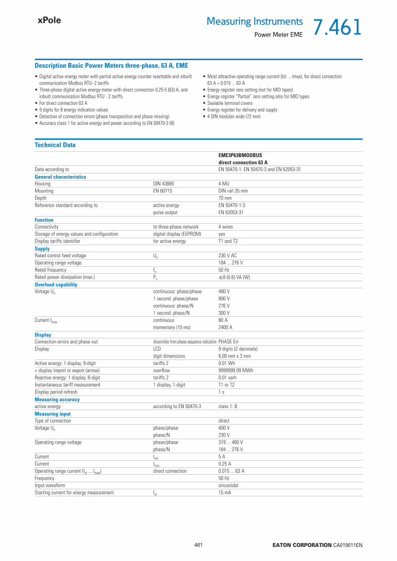
461 EATON CORPORATION CA019011EN
7.461Measuring InstrumentsPower Meter EME
Description Basic Power Meters three-phase, 63 A, EME
• Digital active energy meter with partial active energy counter resettable and inbuilt communication Modbus RTU- 2 tariffs
• Three-phase digital active energy-meter with direct connection 0.25-5 (63) A, and inbuilt communication Modbus RTU - 2 tariffs
• For direct connection 63 A• 9 digits for 8 energy indication values• Detection of connection errors (phase transposition and phase missing)• Accuracy class 1 for active energy and power according to EN 50470-3 (B)
• Most attractive operating range current (Ist ... Imax), for direct connection 63 A = 0.015 ... 63 A
• Energy register zero setting (not for MID types)• Energy register “Partial” zero setting also for MID types• Sealable terminal covers• Energy register for delivery and supply• 4 DIN modules wide (72 mm)
Technical DataEME3P63BMODBUSdirect connection 63 A
Data according to EN 50470-1. EN 50470-3 and EN 62053-31General characteristicsHousing DIN 43880 4 MUMounting EN 60715 DIN rail 35 mmDepth 70 mmReference standard according to active energy EN 50470-1-3
pulse output EN 62053-31FunctionConnectivity to three-phase network 4 wiresStorage of energy values and confi guration digital display (EEPROM) yesDisplay tariffs identifi er for active energy T1 and T2SupplyRated control feed voltage Un 230 V ACOperating range voltage 184 ... 276 VRated frequency fn 50 HzRated power dissipation (max.) Pv 8 (0.6) VA (W)Overload capabilityVoltage Un continuous: phase/phase 480 V
1 second: phase/phase 800 Vcontinuous: phase/N 276 V1 second: phase/N 300 V
Current Imax continuous 80 Amomentary (10 ms) 2400 A
DisplayConnection errors and phase out discernible from phase-sequence indication PHASE ErrDisplay LCD 9 digits (2 decimals)
digit dimensions 6.00 mm x 3 mmActive energy: 1 display, 9-digit tariffs 2 0.01 Wh+ display import or export (arrow) overfl ow 9999999.99 MWhReactive energy: 1 display, 8-digit tariffs 2 0.01 varhInstantaneous tariff measurement 1 display, 1-digit T1 or T2Display period refresh 1 sMeasuring accuracyactive energy according to EN 50470-3 class 1: BMeasuring inputType of connection directVoltage Un phase/phase 400 V
phase/N 230 VOperating range voltage phase/phase 319 ... 480 V
phase/N 184 ... 276 VCurrent Iref 5 ACurrent Imin 0.25 AOperating range current (Ist ... Imax) direct connection 0.015 ... 63 AFrequency 50 HzInput waveform sinusoidalStarting current for energy measurement Ist 15 mA
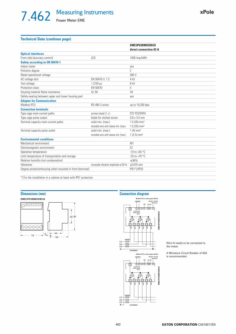
462 EATON CORPORATION CA019011EN
7.462Measuring Instruments
Power Meter EME
Technical Data (continue page)EME3P63BMODBUSdirect connection 63 A
Optical interfacesFront side (accuracy control) LED 1000 Imp/kWhSafety according to EN 50470-1Indoor meter yesPollution degree 2Rated operational voltage 300 VAC voltage test EN 50470-3. 7.2 4 kVTest voltage 1.2/50 μs 6 kVProtection class EN 50470 IIHousing material fl ame resistance UL 94 V0Safety-sealing between upper and lower housing part yesAdaptor for CommunicationModbus RTU RS-485 3 wires up to 19,200 bpsConnection terminalsType cage main current paths screw head Z +/- PZ2 POZIDRIVType cage pulse output blade for slotted screw 0.8 x 3.5 mmTerminal capacity main current paths solid min. (max.) 1.5 (35) mm2
stranded wire with sleeve min. (max.) 1.5 (35) mm2
Terminal capacity pulse outlet solid min. (max.) 1 (4) mm2
stranded wire with sleeve min. (max.) 1 (2.5) mm2
Environmental conditionsMechanical environment M1Electromagnetic environment E2Operative temperature -10 to +55 °CLimit temperature of transportation and storage -25 to +70 °CRelative humidity (not condensation) 80%Vibrations sinusoidal vibration amplitude at 50 Hz ±0.075 mmDegree protectionhousing when mounted in front (terminal) IP51*)/IP20
*) For the installation in a cabinet at least with IP51 protection
Dimensions (mm) Connection diagram
Wire N needs to be connected to the meter.
A Miniature Circuit Breaker of 63A is recommended.

463 EATON CORPORATION CA019011EN
7.463Measuring InstrumentsMultimeter EME3PMMCT5
Multimeter EME3PMMCT5
Communication link TypeDesignation
Article No. Units perpackage
SG14413 S0 EME3PMMCT5 171631 1

464 EATON CORPORATION CA019011EN
7.464Measuring Instruments
Multimeter EME3PMMCT5
Description Multimeter EME3PMMCT5
• The Eaton Multimeter offer an extremely compact multifunction solution for switch-gear and incoming or outgoing feeders in industrial plants and buildings like offi ces, hospitals, universities and so on
• Can be connected to three phase networks via current transformers (.../5A till 10.000/5A)
• Three phase 38 readouts, imported and exported power• Clear readable LED display that reports all measurements through a user-friendly
interface controlled directly from the front panel• Analysis of the different loads on each phase to identify displacements, asymmetri-
cal or unbalanced conditions
• Offers a range of different options to combine and assess measured values• Provided with 2 S0 outputs report active and reactive energy• Two different tariffs settled by an external energy counter (Wh and VArh)• With a side IrDA interface for external communication• External communication allows for the transmission of measured values to a remote
energy management system• 6 modules housing for DIN rail mounting• User can display continuously fi ve indicated values
Technical DataEME3PMMCT5
Communication link S0Connection .../5 AHousing (width) 6 DIN modulesMeasuring voltage range 50 .., 276 / 87 .., 480 V ACFrequency range 49 .., 51 HzStarting current Ist 3 mAReference current Iref 5 AMain supply auxiliary 184 .., 276 V ACSystem connectivity 2 - 3 - 4 wiresDisplay LEDDisplay green backlighted yesMain terminal 4 mm2
Operative temperature -10 to +55 °CPulse output SO 2Measuring accuracy
EN 50470-1-3 active energy class 1: B (1%)EN 62053-23 reactive energy class 2: 2%
Voltage L1, L2, L3
L1-2, L2-3, L3-1
Current L1, L2, L3
N
Power factor L1, L2, L3
L
Frequency
Effective power L1, L2, L3
L
Reactive power L1, L2, L3
L
Apparent power L1, L2, L3
L
Import active energy L1, L2, L3, L
tariff 1 and 2
Export active energy L1, L2, L3, L
tariff 1 and 2
Import reactive energy L1, L2, L3, L
tariff 1 and 2
Export reactive energy L1, L2, L3, L
tariff 1 and 2
Communication ()IR-side: M-Bus, Modbus RTU, KNX, LAN-TCP/IP, SD-Card yes
= Measured parameters displayed, = Measured parameters through IR side modules
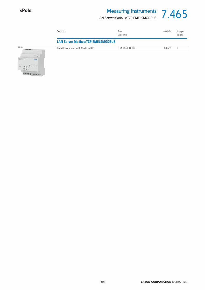
465 EATON CORPORATION CA019011EN
7.465Measuring InstrumentsLAN Server Modbus/TCP EMELSMODBUS
LAN Server Modbus/TCP EMELSMODBUS
Description TypeDesignation
Article No. Units perpackage
SG14313 Data Concentrator with Modbus/TCP EMELSMODBUS 170509 1

466 EATON CORPORATION CA019011EN
7.466Measuring Instruments
LAN Server Modbus/TCP EMELSMODBUS
Description LAN Server Modbus/TCP EMELSMODBUS
Overview:The LAN Servers are Plug-and-Play data concentrators for Energy Meter, Network Analyzer and Power Meter products. The LAN Server allows an easy and reliable connection of several instruments to a data communication network. It is an innovative product designed to implement fast data communication between a supervisory PC and a set of measurement instruments connected through LAN, WAN or Internet. Instruments may be of different kinds and are automatically recognized through a unique coding.
LAN Server Modbus/TCP:This Plug-and-Play product collects the measurement data from different devices connected via a Modbus serial bus. Data are made available on LAN, WAN or Intranet through an HTTP interface and are accessible using simultaneously a standard browser or a Modbus/TCP Application.The LAN Server Modbus/TCP requires an auxiliary at 230 V AC power supply.
Common features• Worldwide communication with measuring devices• Hardware connection through RJ45• TCP/IP data protocol• HTTP for web server• FTP for fi le transfer• NTP for time synchronization• Static or DHCP based addressing• DDNS to maintain a host name, accessible on the internet, without the need for a
static IP• Plug-and-play technology• Internet browser user interface, three languages• Password-protected site access• Internal memory: 2 Gigabytes available for long period storage• 4 DIN modules wide (72 mm)
Technical DataEMELSMODBUS
Type LAN Server Modbus/TCPDescription Data Concentrator with Modbus/TCPAccording to norm general EN 61000-6-2-3, EN 61000-4-2 yesAccording to norm general EN 60950Device width 4 modulesPower supplyVoltage range 230 V AC ±20 %Auxiliary power rating 10 VAFrequency range 45 ... 65 HzOperation featureMemory storage internal 2 GigabyteLAN - HW Interface RJ 45LAN - SW Protocol TCP/IPLAN - Bandrate 10/100 Mbit/sApplication level protocols HTTP - FTP - Modbus/TCPInterface to instruments RS485HW Interface 3 Screw-type terminalsSW Protocol Modbus RTU and ASCIIDirectly connected instruments 31S0 impulse input –Safety accoording to IEC 60950Pollution degree 2Overvoltage category IIOperating voltage ... 300 VACTest voltage impulse
(1.2/50 μs) peak value 4 kV50 Hz 1 min 4 kV
Environmental conditionOperative temperature -10 to 55 °CLimit temperature of storage -25 to 70 °CRelative humidity (non condensing) 80%Vibrations amplitude at 50 Hz ±0.25 mmProtection class IIDegree of protection IP20
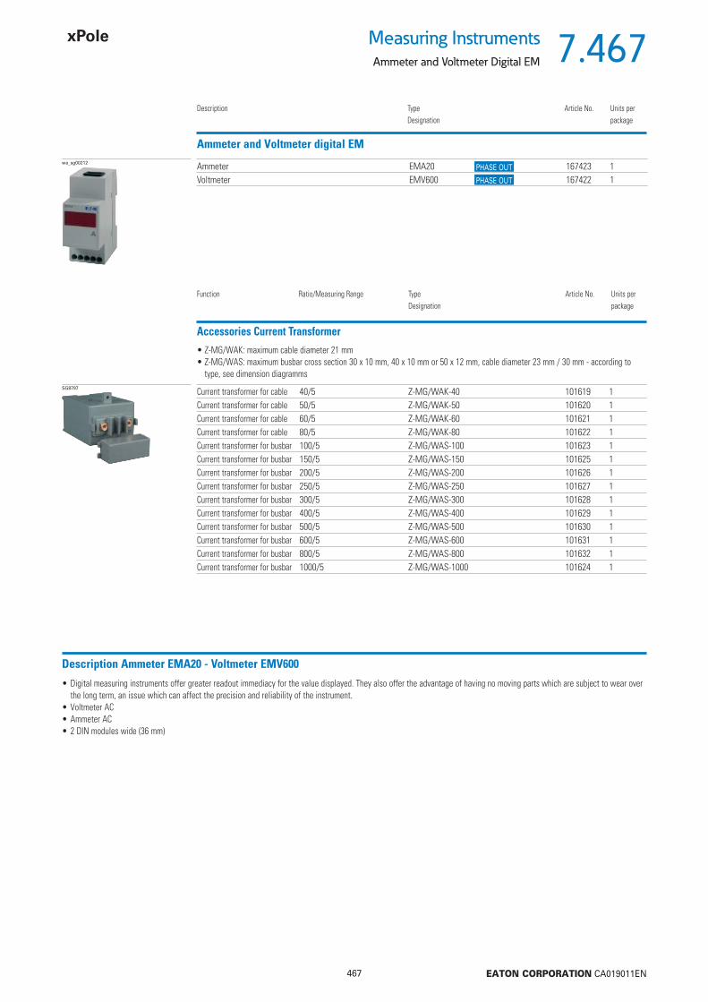
467 EATON CORPORATION CA019011EN
7.467Measuring InstrumentsAmmeter and Voltmeter Digital EM
Ammeter and Voltmeter digital EM
Description TypeDesignation
Article No. Units perpackage
wa_sg00212 Ammeter EMA20 167423 1Voltmeter EMV600 167422 1
Accessories Current Transformer
Function Ratio/Measuring Range TypeDesignation
Article No. Units perpackage
SG8797 Current transformer for cable 40/5 Z-MG/WAK-40 101619 1Current transformer for cable 50/5 Z-MG/WAK-50 101620 1Current transformer for cable 60/5 Z-MG/WAK-60 101621 1Current transformer for cable 80/5 Z-MG/WAK-80 101622 1Current transformer for busbar 100/5 Z-MG/WAS-100 101623 1Current transformer for busbar 150/5 Z-MG/WAS-150 101625 1Current transformer for busbar 200/5 Z-MG/WAS-200 101626 1Current transformer for busbar 250/5 Z-MG/WAS-250 101627 1Current transformer for busbar 300/5 Z-MG/WAS-300 101628 1Current transformer for busbar 400/5 Z-MG/WAS-400 101629 1Current transformer for busbar 500/5 Z-MG/WAS-500 101630 1Current transformer for busbar 600/5 Z-MG/WAS-600 101631 1Current transformer for busbar 800/5 Z-MG/WAS-800 101632 1Current transformer for busbar 1000/5 Z-MG/WAS-1000 101624 1
• Z-MG/WAK: maximum cable diameter 21 mm• Z-MG/WAS: maximum busbar cross section 30 x 10 mm, 40 x 10 mm or 50 x 12 mm, cable diameter 23 mm / 30 mm - according to
type, see dimension diagramms
Description Ammeter EMA20 - Voltmeter EMV600
• Digital measuring instruments offer greater readout immediacy for the value displayed. They also offer the advantage of having no moving parts which are subject to wear over the long term, an issue which can affect the precision and reliability of the instrument.
• Voltmeter AC• Ammeter AC• 2 DIN modules wide (36 mm)
PHASE OUT
PHASE OUT
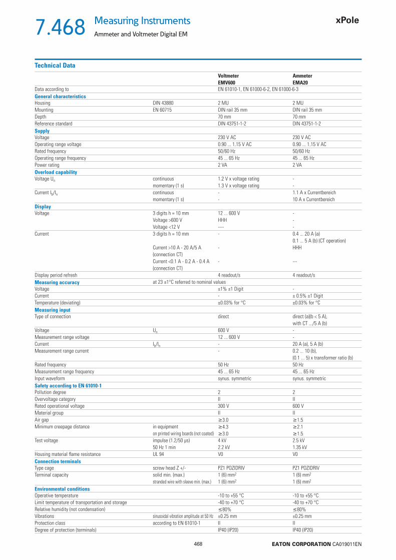
468 EATON CORPORATION CA019011EN
7.468Measuring Instruments
Ammeter and Voltmeter Digital EM
Technical DataVoltmeter AmmeterEMV600 EMA20
Data according to EN 61010-1, EN 61000-6-2, EN 61000-6-3General characteristicsHousing DIN 43880 2 MU 2 MUMounting EN 60715 DIN rail 35 mm DIN rail 35 mmDepth 70 mm 70 mmReference standard DIN 43751-1-2 DIN 43751-1-2SupplyVoltage 230 V AC 230 V ACOperating range voltage 0.90 ... 1.15 V AC 0.90 ... 1.15 V ACRated frequency 50/60 Hz 50/60 HzOperating range frequency 45 ... 65 Hz 45 ... 65 HzPower rating 2 VA 2 VAOverload capabilityVoltage Un continuous 1.2 V x voltage rating -
momentary (1 s) 1.3 V x voltage rating -Current Ib/In continuous - 1.1 A x Currentbereich
momentary (1 s) - 10 A x CurrentbereichDisplayVoltage 3 digits h = 10 mm 12 ... 600 V -
Voltage >600 V HHH -Voltage <12 V ---- -
Current 3 digits h = 10 mm - 0.4 ... 20 A (a)0.1 ... 5 A (b) (CT operation)
Current >10 A - 20 A/5 A - HHH(connection CT)Current <0.1 A - 0.2 A - 0.4 A - ---(connection CT)
Display period refresh 4 readout/s 4 readout/sMeasuring accuracy at 23 ±1°C referred to nominal valuesVoltage ±1% ±1 Digit -Current - ± 0.5% ±1 DigitTemperature (deviating) ±0.03% for °C ±0.03% for °CMeasuring inputType of connection direct direct (a)(b < 5 A),
with CT .../5 A (b)Voltage Un 600 V -Measurement range voltage 12 ... 600 V -Current Ib/In - 20 A (a), 5 A (b)Measurement range current - 0.2 ... 10 (b),
(0.1 ... 5) x transformer ratio (b)Rated frequency 50 Hz 50 HzMeasurement range frequency 45 ... 65 Hz 45 ... 65 HzInput waveform synus. symmetric synus. symmetricSafety according to EN 61010-1Pollution degree 2 2Overvoltage category II IIRated operational voltage 300 V 600 VMaterial group II IIAir gap 3.0 1.5Minimum creepage distance in equipment 4.3 2.1
on printed wiring boards (not coated) 3.0 1.5Test voltage impulse (1.2/50 μs) 4 kV 2.5 kV
50 Hz 1 min 2.2 kV 1.35 kVHousing material fl ame resistance UL 94 V0 V0Connection terminalsType cage screw head Z +/- PZ1 POZIDRIV PZ1 POZIDRIVTerminal capacity solid min. (max.) 1 (6) mm2 1 (6) mm2
stranded wire with sleeve min. (max.) 1 (6) mm2 1 (6) mm2
Environmental conditionsOperative temperature -10 to +55 °C -10 to +55 °CLimit temperature of transportation and storage -40 to +70 °C -40 to +70 °CRelative humidity (not condensation) 80% 80%Vibrations sinusoidal vibration amplitude at 50 Hz ±0.25 mm ±0.25 mmProtection class according to EN 61010-1 II IIDegree of protection (terminals) IP40 (IP20) IP40 (IP20)

469 EATON CORPORATION CA019011EN
7.469Measuring InstrumentsAmmeter and Voltmeter Digital EM
Dimensions (mm) Connection diagram

470 EATON CORPORATION CA019011EN
7.470Measuring Instruments
Ammeter and Voltmeter digital EM
Description Current transformer for cable Z-MG/WAK, Current transformer for busbar Z-MG/WAS
• Transform high currents to standard measuring currents• Current transformers help to cut costs when installing and connecting busbar system• Recommended from 40 A upward• Accuracy classes
Class 0.5: for accurate measurement and calibrated kWh-metersClass 1: for general measurement and non-calibrated kWh-metersClass 3: for coarse measurement, relays and for protection
• When winding several turns of the primary cable around the current transformer, you will receive half the primary current per turn while power and class remain unchanged.
Technical DataZ-MG/WAK Z-MG/WAS
ElectricalMax. Rated operational voltage 720 V 720 VSecondary current 5 A 5 ARated frequency 50-60 Hz 50-60 HzCable diameter 21 mm 23 mm, 30 mmBusbar cross section – 30 x 10 mm, 40 x 10 mm, 50 x 12 mmPrimary nominal current IpN class P [VA] class P [VA]
40 A 3 1.350 A 3 1.560 A 3 1.580 A 3 2100 A 1 1.5150 A 1 3200 A 1 3250 A 0.5 2300 A 0.5 2400 A 0.5 3500 A 0.5 10600 A 0.5 10800 A 0.5 101000 A 0.5 10
Connections P1 (K) primary input, P2 (L) primary output, s1 (k) secondary input, s2 (l) secondary outputNominal thermic short-time current Ith 60 x IpN for 1 s 60 x IpN for 1 sNominal dynamic short circuit current Idyn 2.5 x Ith for 1 s 2.5 x Ith for 1 sPermanent overload 1.2 x IpN 1.2 x IpN
Insulating class IEC 85 E ETest voltage 50 Hz / 1 min. 6 kV 6 kVMechanicalMounting quick fastening on DIN rail IEC/EN 60715.
wall mounting,directly onto the cable or onto busbar
Degree of protection IP30 IP30Secondary connection plug-in terminals 6.3 mm plug-in terminals 6.3 mmPermitted relative air humidity 80% 80%Temperature range -20 to +50 °C -20 to +50 °CMax. temperature of busbars – 70 °C
Dimensions (mm)
Connection diagram

471 EATON CORPORATION CA019011EN
7.471Measuring InstrumentsOperating Hours Counter ASOHC230
Operating Hours Counter ASOHC230
Display Rated voltage TypeDesignation
Article No. Units perpackage
wa_sg04411 5+2 digit 230 V 50Hz ASOHC230 167424 1
Description Operating Hours Counter ASOHC230
• The operating hours counter registers the operating hours to an accuracy of two decimals (hundredths of a second).• Power supply for terminals 1 and 3 of the electronic counter is required to enable the device to continuously display the measured values. If terminal 3 is supplied with voltage
(at DC “+“), the counting process will get started. • In case of a power failure, the counting result will be saved for an indefi nite period of time (EEPROM). Once power is back again, counting will be continued from the value that
has been saved before.• Time counters are used for a reliable collection of production and service hours, which allows an accurate planning and monitoring of production processes, maintenance cycles
and warranty periods.
Technical DataASOHC230
Standards DIN VDE 0435-110, DIN EN 60255-6, UL 863Approvals UL 863, UL File No. E300537, CSA C22.2 No. 6 and 55Rated control feed voltage Uc 230 V ACAuxiliary voltage range at 50/60 Hz 0.9 ... 1.1 x Uc
Rated frequency 50 HzAuxiliary power rating Pv <1 VAType of operation counting of hoursDisplay Cyclometer register 00000,00 hConnection terminals ±screws (Philips) 1Terminal capacity solid 1.5 mm2
stranded wire with sleeve min. 0.75 mm2
Permitted ambient temperature -10 ... +70 °CDegree of protection according to DIN EN 60529 IP20, with conductors connectedProtection class according to DIN EN 61140 / VDE 0140 IIAllowed range of air humidity <80 %
Connection diagram
Dimensions (mm)

472 EATON CORPORATION CA019011EN
7.472Measuring Instruments
Pulse Counter ASPC230
Pulse Counter ASPC230
Display Rated voltage TypeDesignation
Article No. Units perpackage
wa_sg05011 7 digits 230 V 50Hz ASPC230 167425 1
Description Pulse Counter ASPC230
• The pulse counter sums up the number of pulses, e.g. how many times a device is switched on.• Power supply for terminals 1 and 3 of the electronic counter is required to enable the device to continuously display the measured values. If terminal 3 is supplied with voltage
(at DC “+“), the counting process will get started.• In case of a power failure, the counting result will be saved for an indefi nite period of time (EEPROM). Once power is back again, counting will be continued from the value that
has been saved before.• Pulse counters are used for a reliable collection of production and service hours, which allows an accurate planning and monitoring of production processes, maintenance cycles
and warranty periods.• Pulse counting is used for general quantity counting, registration of the switch-on frequency, and for the collection of switch-on cycles or production quantities in systems and
machines.
Technical DataASPC230
Standards DIN VDE 0435-110, DIN EN 60255-6, UL 863Approvals UL 863, UL File No. E300537, CSA C22.2 No. 6 and 55Rated control feed voltage Uc 230 V ACAuxiliary voltage range at 50/60 Hz 0.9 ... 1.1 x Uc
Rated frequency 50/60 HzAuxiliary power rating Pv <1 VAType of operation counting of pulsesDisplay Cyclometer register 0000000
LCD display -- h--
Frequency of counting 10 HzPulse duration 50 msResetting electrical components --
mechanical components --Connection terminals ±screws (Philips) 1Terminal capacity solid 1.5 mm2
stranded wire with sleeve min. 0.75 mm2
Permitted ambient temperature -10 ... +70 °CDegree of protection according to DIN EN 60529 IP20, with conductors connectedProtection class according to DIN EN 61140 / VDE 0140 IIAllowed range of air humidity <80 %
Dimensions (mm)
Connection diagram

473 EATON CORPORATION CA019011EN
8.473Other Accessoriesx
sg68912 138103900

474 EATON CORPORATION CA019011EN
8.474Other Accessories
Protective Earth Socket Z-SD230
Protective Earth Socket Z-SD230
Design TypeDesignation
Article No. Units perpackage
sg68912 Standard Z-SD230 266875 10 / 50Child protection device and earth pin Z-SD230-BS 266876 10 / 50
Accessories Busbar Block Busbar Z-SV-10/1P+N-SD 269526 10
End caps Z-V-AK/2+3P 264930 10 / 600
Description Protective Earth Socket Z-SD230
• Design according to VDE, ÖVE• Modular busbar connection system L/N• Screw fastening is possible• Width 2.5MU• Busbar block Z7-SD/1P+N 10 mm2 available• Model -BS with child protection device and earth pin
Technical DataZ-SD230
ElectricalRated voltage 250 V ACRated current 10/16 AMechanicalFrame size 45 mmDevice height 76 mmDevice width 44 mmMounting quick fastening on DIN rail IEC/EN 60715, screw-mounting possibleDegree of protection, built-in IP40Upper and lower terminals lift terminalsTerminal capacity 1 to 2x2.5 mm2
Connection diagram
Dimensions (mm)Z-SD230 Z-SD230-BS

475 EATON CORPORATION CA019011EN
8.475Other AccessoriesNeutral Conductor Lead-Through Terminal, Feed Terminal Z-D
Neutral Conductor Lead-Through Terminal, Feed Terminal Z-D
Rated current / Design TypeDesignation
Article No. Units perpackage
SG59511 63 A Z-D63 248267 12/12063 A with test socket Z-D63/P 248268 12/120100 A Z-D80 248269 12/120
Description Neutral Conductor Lead-Through Terminal, Feed Terminal Z-D
• Compatible with standard busbar to Xtra Combination devices• Z-D80: Feeder block for busbar system 80 A. Lift terminal (35 mm2) and open mouthed terminal above, lift terminal (50 mm2) below. Busbar positioning optionally above or below• Z-D80: with testing bush 4 mm Ø, 10 A for N-conductor
Technical DataZ-D63 Z-D63/P Z-D80
ElectricalRated current 63 A 63 A 100 AFrequency 50-60 Hz 50-60 Hz 50-60 HzN-conductor test bush – 10 A, Ø 4 mm –MechanicalFrame size 45 mm 45 mm 45 mmDevice height 80 mm 80 mm 80 mmDevice width 17.5 mm (1MU) 17.5 mm (1MU) 17.5 mm (1MU)Mounting quick fastening with 2 lock-in positions on DIN rail IEC/EN 60715Degree of protection, built-in IP40 IP40 IP40Terminals
above open mouthed/lift terminals open mouthed/lift terminals open mouthed/lift terminalsbelow open mouthed/lift terminals open mouthed/lift terminals lift terminals
Terminal capacityabove 1-25 mm2 1-25 mm2 1-35 mm2
below 1-25 mm2 1-25 mm2 2.5-50 mm2
Busbar thickness 0.8 - 2 mm 0.8 - 2 mm 0.8 - 2 mm
Connection diagramZ-D63 Z-D63/P Z-D80
Dimensions (mm)Z-D63 Z-D63/P Z-D80
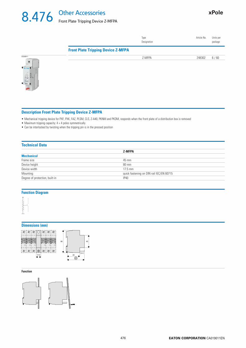
476 EATON CORPORATION CA019011EN
8.476Other Accessories
Front Plate Tripping Device Z-MFPA
Front Plate Tripping Device Z-MFPA
TypeDesignation
Article No. Units perpackage
SG58911 Z-MFPA 248302 6 / 60
Description Front Plate Tripping Device Z-MFPA
• Mechanical tripping device for PXF, PXK, FAZ, PLSM, CLS, Z-A40, PKNM and PKDM, responds when the front plate of a distribution box is removed• Maximum tripping capacity: 4 + 4 poles symmetrically• Can be interlocked by twisting when the tripping pin is in the pressed position
Technical DataZ-MFPA
MechanicalFrame size 45 mmDevice height 80 mmDevice width 17.5 mmMounting quick fastening on DIN rail IEC/EN 60715Degree of protection, built-in IP40
Function Diagram
Dimensions (mm)
Function

477 EATON CORPORATION CA019011EN
8.477Other AccessoriesCircuit Description GR, Plastic Box Z-BOX
Circuit Description GR
Number of Circuits Dimensions(mm)
TypeDesignation
Article No. Units perpackage
138103900 30 210x120 GR-2 138103900 190 210x300 GR-3 138104100 1
• Self-adhesive table for synoptic description of circuits, to be attached inside or on a distribution box.• Pre-printed individual adhesive labels for device designation included
Plastic Box Z-BOX
Colour Dimensions(mm)
TypeDesignation
Article No. Units perpackage
SG81411 blue 45x54x75 Z-BOX/BLA 286062 12/120
• Empty, can be snapped onto DIN rail• For spare fuse links, small spare parts
Eaton Industries (Austria) GmbH
Scheydgasse 421210 ViennaAustria
9010238132641
Eaton
EMEA HeadquartersRoute de la Longeraie 71110 Morges, SwitzerlandEaton.eu
© 2019 EatonAll Rights ReservedPrinted in Austria Publication No. CA019011ENArticle number 300933-MKOctober 2019Grafi cs: SRA, Schrems
Follow us on social media to get the latest product and support information.Eaton is a registered trademark.
All other trademarks are property of their respective owners.
To contact us please visit http://www.eaton.eu/Europe/Electrical/CustomerSupport/ContactDetails/index.htmFor Technical Support please get in contact [email protected]
Changes to the products, to the information contained in thisdocument, and to prices are reserved; as are errors and omissions.Only order confirmations and technical documentation by Eaton isbinding. Photos and pictures also do not warrant a specific layout orfunctionality. Their use in whatever form is subject to prior approvalby Eaton. The same applies to trademarks (especially Eaton, Moeller,and Cutler-Hammer). The Terms and Conditions of Eaton apply, asreferenced on Eaton Internet pages and Eaton order confirmations.
Eaton is a power management company with 2018 sales of $21.6 billion. We provide energy-effi cient solutions that help our customers effectively manage electrical, hydraulic and mechanical power more effi ciently, safely and sustainably. Eaton is dedicated to improving the quality of life and the environment through the use of power management technologies and services. Eaton has approximately 99,000 employees and sells products to customers in more than 175 countries.
For more information, visit Eaton.com.
Related Documents


