NB THIS LEAFLET MUST BE LEFT WITH THE CONSUMER AFTER INSTALLATION; GUARANTEE AND IMPORTANT MAINTENANCE INFORMATION ENCLOSED. Installation, Care and Maintenance Manual Warranty Registration Document

Welcome message from author
This document is posted to help you gain knowledge. Please leave a comment to let me know what you think about it! Share it to your friends and learn new things together.
Transcript

NB THIS LEAFLET MUST BE LEFT WITH THE CONSUMER AFTER INSTALLATION; GUARANTEE AND IMPORTANT MAINTENANCE INFORMATION ENCLOSED.
Installation, Care and Maintenance Manual Warranty Registration Document

2
3
About your metis worktops These worktops were developed to make solid
surface an easy fit option without the need for
specialist templating or tooling. By following
these instructions we know that competent
installers can achieve excellent results. Preparation
The work surfaces and additional materials must be conditioned for at least 24 hours at room temperature prior to fitting.
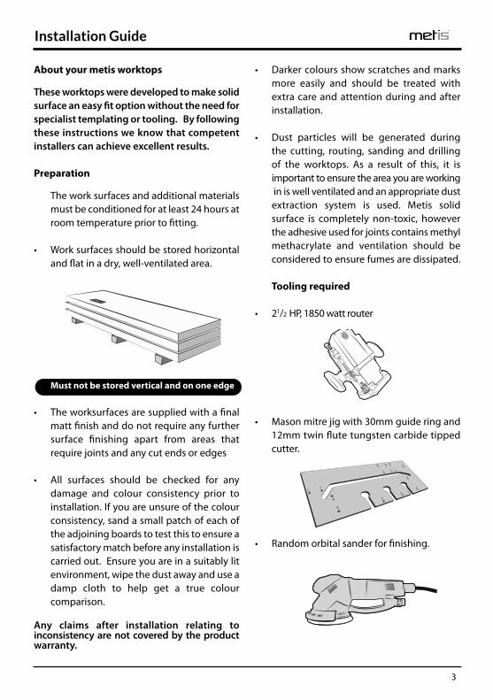
• Work surfaces should be stored horizontal
and flat in a dry, well-ventilated area. u
Must not be stored vertical and on one edge • The worksurfaces are supplied with a final matt finish and do not require any further
surface finishing apart from areas that require joints and any cut ends or edges
• All surfaces should be checked for any
damage and colour consistency prior to installation. If you are unsure of the colour consistency, sand a small patch of each of the adjoining boards to test this to ensure a satisfactory match before any installation is carried out. Ensure you are in a suitably lit environment, wipe the dust away and use a damp cloth to help get a true colour comparison.
Any claims after installation relating to inconsistency are not covered by the product warranty.
• Darker colours show scratches and marks more easily and should be treated with extra care and attention during and after installation.
• Dust particles will be generated during
the cutting, routing, sanding and drilling of the worktops. As a result of this, it is important to ensure the area you are working in is well ventilated and an appropriate dust extraction system is used. Metis solid surface is completely non-toxic, however the adhesive used for joints contains methyl methacrylate and ventilation should be considered to ensure fumes are dissipated.
Tooling required • 21/2 HP, 1850 watt router • Mason mitre jig with 30mm guide ring and
12mm twin flute tungsten carbide tipped cutter.
• Random orbital sander for finishing.
Installation Guide

4
• Hot Melt Glue gun, glue, clamps orSeaming Tools
• Also required: Jointing kit - 1 kit per joint.
This kit is supplied with 2 part acrylic adhesive (10:1 adhesive and activator), 2 isopropyl alcohol wipes, 6 MDF Jointing Blocks and sandpapers in the followinggrades: P120, P240, P320 grit and grey abrasive pad.
• We do not recommend the use of any
finishing products to enhance the appearance of these worktops other than those supplied in the Care Kit. The surface is factory finished to a matt finish and we do not recommend that a higher gloss level is attempted.
• Only use the sanding grades recommended
in this installation guide.
Planning your layout • Angled joints must always be supported by
either wall battens or cabinetry. • No joints should be made above a dish
washer, washing machine, washer dryer or in the area around cut-outs.
• Joints should be at least 100mm away from
all cut-outs and dishwasher installations. • A maximum overhang of 300mm is
recommended with metis surfaces with support brackets required if the length of the overhang is over 600mm. The maximum unsupported span – e.g. above an appliance - is 600mm. Brackets or support legs must be used for longer spans.
• Where a cabinet cannot offer full support,
additional bracing must be added to the cabinet to ensure full support of joint at the front and the back. All joints should be supported across at least 3 points.
Min100
Min100
Min100
2400mm
900m
m 600m
m
450mm 600mm 450mm600mm
300m
m
SUPPORTED AREA
UNSUPPORTED OVERHANG
5
• If any additional fixings are needed in the worksurface, you will need to drill a hole, and then use adhesive to secure a brass insert into the hole. You can then screw into the insert – Do not screw directly into the surface as this can cause the surface to split.
Slow Cookers • As all slow cookers may operate at varying
temperatures, we would always advise use of a trivet, chopping board, heat mat etc. to protect the surface from any damage.
Freestanding cookers • Ensure that the level of the hob does not sit
below the worktop as this can cause direct transfer of heat or flame towards the acrylic surface.
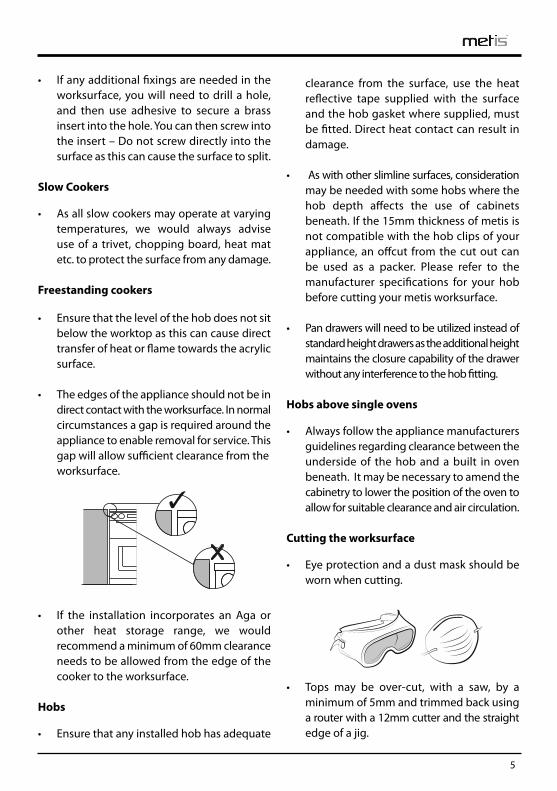
• The edges of the appliance should not be in
direct contact with the worksurface. In normal circumstances a gap is required around the appliance to enable removal for service. This gap will allow sufficient clearance from the worksurface.
• If the installation incorporates an Aga or
other heat storage range, we would recommend a minimum of 60mm clearance needs to be allowed from the edge of the cooker to the worksurface.
Hobs • Ensure that any installed hob has adequate
clearance from the surface, use the heat reflective tape supplied with the surface and the hob gasket where supplied, must be fitted. Direct heat contact can result in damage.
• As with other slimline surfaces, consideration
may be needed with some hobs where the hob depth affects the use of cabinets beneath. If the 15mm thickness of metis is not compatible with the hob clips of your appliance, an offcut from the cut out can be used as a packer. Please refer to the manufacturer specifications for your hob before cutting your metis worksurface.
• Pan drawers will need to be utilized instead of
standard height drawers as the additional height maintains the closure capability of the drawer without any interference to the hob fitting.
Hobs above single ovens • Always follow the appliance manufacturers
guidelines regarding clearance between the underside of the hob and a built in oven beneath. It may be necessary to amend the cabinetry to lower the position of the oven to allow for suitable clearance and air circulation.
Cutting the worksurface • Eye protection and a dust mask should be
worn when cutting. • Tops may be over-cut, with a saw, by a
minimum of 5mm and trimmed back using a router with a 12mm cutter and the straight edge of a jig.
6
• Always ensure that both sets of the cut are adequately supported. When cutting from the underside of the material, use a soft pad to avoid scratching.
• If you are cutting using a hand held skill/
circular saw then cut face up. Cut edge should always be clean cut with the router.
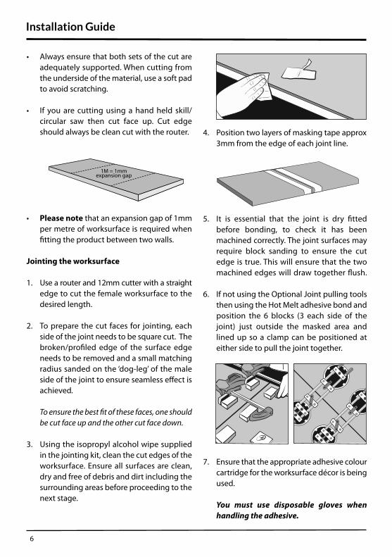
• Please note that an expansion gap of 1mm
per metre of worksurface is required when fitting the product between two walls.
Jointing the worksurface 1. Use a router and 12mm cutter with a straight
edge to cut the female worksurface to the desired length.
2. To prepare the cut faces for jointing, each
side of the joint needs to be square cut. The broken/profiled edge of the surface edge needs to be removed and a small matching radius sanded on the ‘dog-leg’ of the male
side of the joint to ensure seamless effect is achieved.
To ensure the best fit of these faces, one should be cut face up and the other cut face down.
3. Using the isopropyl alcohol wipe supplied
in the jointing kit, clean the cut edges of the worksurface. Ensure all surfaces are clean, dry and free of debris and dirt including the surrounding areas before proceeding to the next stage.
4. Position two layers of masking tape approx
3mm from the edge of each joint line. 5. It is essential that the joint is dry fitted
before bonding, to check it has been machined correctly. The joint surfaces may require block sanding to ensure the cut edge is true. This will ensure that the two machined edges will draw together flush.
6. If not using the Optional Joint pulling tools
then using the Hot Melt adhesive bond and position the 6 blocks (3 each side of the joint) just outside the masked area and lined up so a clamp can be positioned at either side to pull the joint together.
7. Ensure that the appropriate adhesive colour
cartridge for the worksurface décor is being used.
You must use disposable gloves when handling the adhesive.
1M = 1mmexpansion gap
Installation Guide
7
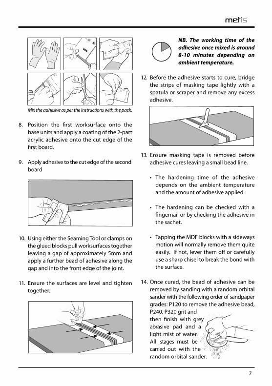
Mix the adhesive as per the instructions with the pack. 8. Position the first worksurface onto the
base units and apply a coating of the 2-part acrylic adhesive onto the cut edge of the first board.
9. Apply adhesive to the cut edge of the second
board 10. Using either the Seaming Tool or clamps on
the glued blocks pull worksurfaces together leaving a gap of approximately 5mm and apply a further bead of adhesive along the gap and into the front edge of the joint.
11. Ensure the surfaces are level and tighten
together.
NB. The working time of the adhesive once mixed is around 8-10 minutes depending on ambient temperature.
12. Before the adhesive starts to cure, bridge
the strips of masking tape lightly with a spatula or scraper and remove any excess adhesive.
13. Ensure masking tape is removed before
adhesive cures leaving a small bead line.
• The hardening time of the adhesive depends on the ambient temperature and the amount of adhesive applied.
• The hardening can be checked with a
fingernail or by checking the adhesive in the sachet.
• Tapping the MDF blocks with a sideways
motion will normally remove them quite easily. If not, lever them off or carefully use a sharp chisel to break the bond with the surface.
14. Once cured, the bead of adhesive can be
removed by sanding with a random orbital sander with the following order of sandpaper grades: P120 to remove the adhesive bead, P240, P320 grit and then finish with grey abrasive pad and a light mist of water. All stages must be carried out with the random orbital sander.
8
Installation Guide
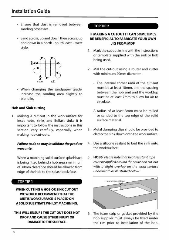
• Ensure that dust is removed between sanding processes.
• Sand across, up and down then across, up
and down in a north - south, east – west style.
• When changing the sandpaper grade,
increase the sanding area slightly to blend in.
Hob and Sink cutting 1. Making a cut-out in the worksurface for
inset hobs, sinks and Belfast sinks it is important to follow the instructions in this section very carefully, especially when making hob cut-outs.
Failure to do so may invalidate the product warranty.
When a matching solid surface splashback is being fitted behind a hob area a minimum of 30mm clearance should be allowed from edge of the hob to the splashback face.
WHEN CUTTING A HOB OR SINK CUT OUT
WE WOULD RECOMMEND THAT THE
METIS WORKSURFACE IS PLACED ON
A SOLID SUBSTRATE WHILST MACHINING.
THIS WILL ENSURE THE CUT OUT DOES NOT
DROP AND CAUSE EITHER INJURY OR
DAMAGE TO THE SURFACE.
IF MAKING A CUTOUT IT CAN SOMETIMES
BE BENEFICIAL TO FABRICATE YOUR OWN
JIG FROM MDF 1. Mark the cut out in line with the instructions
or template supplied with the sink or hob being used.
2. Mill the cut-out using a router and cutter
with minimum 20mm diameter.
• The internal corner radii of the cut-out must be at least 10mm, and the spacing between the hob unit and the worktop must be at least 7mm to allow for air to circulate.
A radius of at least 3mm must be milled
or sanded to the top edge of the solid surface material.
3. Metal clamping clips should be provided to
clamp the sink down onto the worksurface. 4. Use a silicone sealant to bed the sink onto
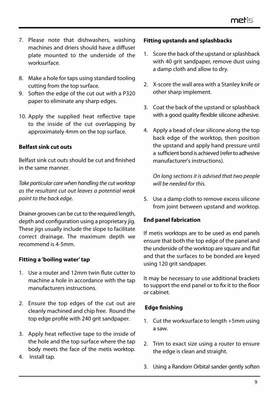
the worksurface. 5. HOBS Please note that heat resistant tape
must be applied around the entire hob cut-out with a slight overlap on the work surface underneath as illustrated below.
6. The foam strip or gasket provided by the
hob supplier must always be fixed under the rim prior to installation of the hob.
Heat resistant tape
TOP TIP 2
TOP TIP 1
START x2
END
9
7. Please note that dishwashers, washing machines and driers should have a diffuser plate mounted to the underside of the worksurface.
8. Make a hole for taps using standard tooling
cutting from the top surface. 9. Soften the edge of the cut out with a P320
paper to eliminate any sharp edges. 10. Apply the supplied heat reflective tape
to the inside of the cut overlapping by approximately 4mm on the top surface.
Belfast sink cut outs Belfast sink cut outs should be cut and finished in the same manner. Take particular care when handling the cut worktop as the resultant cut out leaves a potential weak point to the back edge. Drainer grooves can be cut to the required length, depth and configuration using a proprietary jig. These jigs usually include the slope to facilitate correct drainage. The maximum depth we recommend is 4-5mm. Fitting a ‘boiling water’ tap 1. Use a router and 12mm twin flute cutter to
machine a hole in accordance with the tap manufacturers instructions.
2. Ensure the top edges of the cut out are
cleanly machined and chip free. Round the top edge profile with 240 grit sandpaper.
3. Apply heat reflective tape to the inside of
the hole and the top surface where the tap body meets the face of the metis worktop.
4. Install tap.
Fitting upstands and splashbacks 1. Score the back of the upstand or splashback
with 40 grit sandpaper, remove dust using a damp cloth and allow to dry.
2. X-score the wall area with a Stanley knife or
other sharp implement. 3. Coat the back of the upstand or splashback
with a good quality flexible silicone adhesive. 4. Apply a bead of clear silicone along the top
back edge of the worktop, then position the upstand and apply hand pressure until a sufficient bond is achieved (refer to adhesive manufacturer's instructions).
On long sections it is advised that two people will be needed for this.
5. Use a damp cloth to remove excess silicone
from joint between upstand and worktop. End panel fabrication If metis worktops are to be used as end panels ensure that both the top edge of the panel and the underside of the worktop are square and flat and that the surfaces to be bonded are keyed using 120 grit sandpaper. It may be necessary to use additional brackets to support the end panel or to fix it to the floor or cabinet. Edge finishing 1. Cut the worksurface to length +5mm using
a saw. 2. Trim to exact size using a router to ensure
the edge is clean and straight. 3. Using a Random Orbital sander gently soften
10
Installation Guide
the top edge and surface with the P240, then using the P320 grit and finally with the grey abrasive pad and a light mist of water to blend.
Cutting curves metis worktops can easily be cut to form curves or shapes. We recommend using a jig which should allow you to form clean edges to your required radius. Always remember the jig needs to allow for the size of your router base. Cut edges are simply sanded using the 3 grades of sandpaper and the grey finishing pad. Fitting undermount sink module When planning for utilising a sink module, care should be taken to ensure that any jointing to be completed is not positioned within 100mm from the sink area and that enough additional worksurface is available to complete any required joint into the module. List of components • Sink bowls are supplied separate from the
module so ensure that the correct number of additional cartons are available. e.g The 1 & 1/2 bowl module is supplied in 3 boxes
- sink module, large bowl and small bowl. • Some modules include a pop-up waste
kit. Waste fittings and silicone sealant come with all modules.
1. Unpack module ensuring that all required
components are present and correct. 2. Ensure there are no marks or issues with the
worksurface and sinks before commencing any work.
3. It is important not to stand or kneel on the
sink module area. 4. Dry fit/position the module in the area/cabinet
it is to be fitted. Make sure you have adequate supply of standard worksurface for extension to the module.
5. Ensure you position the module with the
bowls and drainer positioned according to your requirements.
6. Before fitting the bowl(s) and fittings into
position it is recommended that all joints and edgings be machined as described previously in the booklet.
7. Once you are confident all the joints and
edgings have been machined as required.
Dry fit joints to check 8. Unpack stainless steel bowl(s) and fittings
ensuring all components are present and not damaged.
9. Clean the surfaces on the bowl edges to be
mounted and the edge of the module where the sink will be bonded, ensuring that all dust, debris and dirt is removed.
10. Apply a generous bead of the supplied
silicone to the stainless steel bowl edge area and apply to the worksurface ensuring no gaps are left anywhere in the bead to achieve a watertight fit.
11. Apply each sink carefully making sure to
check the waste overflow is positioned correctly and insert screw fixings and sink clips to the underside, carefully applying
11
Handy Tips
and ensuring the screw is not over-tightened as this can result in damage to the material.
DO NOT USE A POWER DRIVER.
USE A HAND TOOL. 12. Check sink positions are even and correct
and adjust if necessary. 13. Position the module in the unit and make
necessary joints into the module as required using the aforementioned processes.
14. Wipe away any excess silicone. 15. Allow 24 hours for the silicone to fully cure
before using the sink (i.e. filling with water). • When tiling down to the worksurface leave
a minimum of 3mm gap between the bottom row of tiles and the worksurface. This gap should be sealed with a silicone sealant.
Do not fill the gap with grout.
• When scribing the worktop to the back wall
use an electric planer with TCT blades. • When fitting sink modules it is a good idea
to dry fit onto the cabinet in order to mark out the positioning of the bowl to the front & back rails of the carcass. This will enable the easy removal of excess rail to allow for correct sink positioning.
• When doing a hob cut out, consideration
may be needed where the hob depth affects the use of cabinets beneath. Please refer to the manufacturer specification for your hob before cutting the work surface.
Before installation please thoroughly
check your surfaces for damage and
colour consistency Surface finish Over a short period of time in use in the home, your worktops will develop a smoother finish and more lustrous appearance. In the first days after installation the dry finish of the surface may show finger marks more readily than it will do when it has achieved this ‘patina’. Regular cleaning with warm soapy water is the usual first step to remove surface marks. It is possible to enhance the surface lustre by using Countertop cleaner; as with any treatment of this nature, the application has to be repeated in order to maintain the same finish across all areas of the kitchen. Initial treatment and cleaning First ensure that your worksurface is thoroughly cleaned with warm soapy water or Fairy Power Spray to remove any greasy residues. A mild abrasive cream cleaner such as Cif cream is also a good part of your regular maintenance regime.
Countertop cleaner Countertop cleaner is designed to give lustre to solid surface worktops – this will be particularly noticeable on darker décors. It will also help to build up the natural patina of your surface and a protective layer that will repel dirt and liquids. We advise to use sparingly, as required. Apply the cleaner using a micro-fibre cloth* and buff to leave a streak free finish. Countertop cleaner will not remove scuffs or scratches but can mask the effect.

12
Care and Maintenance
Please NoteWHENEVER TRYING TO REMOVE MARKS
OR SCRATCHES ALWAYS TRY THE LEAST
SEVERE METHOD FIRST
1. Everyday marks - Using a mild abrasive
cleaner such as Cif cream, work in a circular motion; wipe away all residue and buff dry.
Apply Countertop cleaner if applicable. 2. Fine scuffs and scratches - Cover the
affected area with a liberal amount of soapy water. Place the grey abrasive pad* onto the wet surface and, using a sanding block*
or firm sponge to ensure even spread of pressure, rub over the affected area in a circular motion. A slight paste will be generated that aids the finishing process and helps to maintain the original level of surface finish. Repeat step 1. If marks are still evident, repeat the grey abrasive pad process or, in the case of deeper scratches, move on to step 3.
3. Removal of deeper scratches - Ensure that
the surface is clean and dry before starting. Place the sanding disc* onto the sanding block ensuring that it is located correctly and wrapped onto both sides of the block. Using small circular movements, work a small area around the affected part of the surface. A small amount of dust will be generated – this will need to be wiped off to check progress and before moving onto the next step. When the mark has been removed the repaired area will retain very fine sanding marks; these are removed by repeating step 2 and then step 1 to blend in the refurbished area. Each time you move back through the steps, work a slightly wider area so as to help this blend in.
Items marked with ‘*’ are included as part of the Care Kit available from your retailer.
Darker colours show scratches and marks more
easily and should be treated with extra care
and attention during and after installation.
Your worktops have a 10 year warranty against manufacturing defects. In the unlikely event of there being any problems with this product, please refer in the first instance back to your retailer. It is imperative that the installation and care and maintenance instructions are referred to both before and after installation, as misuse of the worksurface may affect the appearance of the product. This does not affect your statutory rights as a consumer. Complete the form on page 14 or register online at www.metisworksurfaces.co.uk The warranty applies to the first owner and first installation only and is not transferable. 02/20
WARRANTY
13
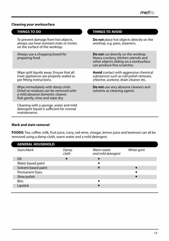
Mark and stain removal FOODS: Tea, coffee, milk, fruit juice, curry, red wine, vinegar, lemon juice and beetroot can all be removed using a damp cloth, warm water and a mild detergent.
GENERAL HOUSEHOLD Stain/Mark Damp Warm water White spirit
cloth and mild detergent Oil • • Water based paint • Solvent based paint • • Permanent Dyes • Shoe polish • Biro • Lipstick •
Cleaning your worksurface
THINGS TO DO
To prevent damage from hot objects, always use heat resistant mats or trivetson the surface of the worktop.
Always use a chopping board for preparing food.
Wipe spilt liquids away. Ensure that all inset appliances are properly sealed as per fitting instructions.
Wipe immediately with damp cloth. Dried on residues can be removed with a mild abrasive domestic cleaner. Rub gently, rinse and wipe dry.
Cleaning with a sponge, water and mild detergent liquid is sufficient for normal maintenance.
THINGS TO AVOID
Do not place hot objects directly on the worktop. e.g. pans, steamers.
Do not cut directly on the worktop. Heavy crockery, kitchen utensils and other objects sliding on a worksurface can produce fine scratches.
Avoid contact with aggressive chemical substances such as nail polish remover, chlorine, acetone, drain cleaner etc.
Do not use very abrasive cleaners and solvents as cleaning agents.

14
Warranty
WARRANTY REGISTRATION FORM: metis
Name ...............................................................................................................................................................................
......................................................................................................................................................................................................
Address............................................................................................................................................................................................
............................................................................................................................................................................................................
............................................................................................................... Post Code ..........................................................
Tel ....................................................................................................................................................................................
Email .....................................................................................................................................................................................
Where did you purchase the work surface?..................................................................................................................
Product reference number................................................................................................................................................
Date of purchase ...........................................................................................................................................................
Product reference number can be found on the metis packaging and on the underneath of the work surface.
To be completed by installer I certify that this metis work surface has been fitted in accordance with the prescribed installation instructions.
Signed.................................................................................................................................................................................
Date ..................................................................................................................................................................................... ....
Please print name ....................................................................................................................................... (FITTER)
Please return to: Sylmar Technology Ltd, Azalea Close,
Clover Nook Industrial Park, Alfreton, Derbyshire DE55 4QX Tel: 01773 521300 Fax: 01773 836837
E-mail: [email protected]
Or register warranty online at www.metisworksurfaces.co.uk Data Protection: Sylmar Technology Limited may use your information for administration, customer analysis, customer service and targeted marketing. We may contact you by email, SMS, telephone, fax or other reasonable methods to let you know about other products, services or promotions that may be of interest to you. If you do not want to receive such information and offers then please tick

15

www.metisworksurfaces.co.ukk
metis is a registered trade mark of Sylmar Technology Limited. 0718/e2700rev001
Related Documents