Doc. No. 502-20-0151-001 Iss 5, Sep 2014 (CN38901-001) Installation and User Guide Titan GSM / GSM-R Telephone GAI-TRONICS .

Welcome message from author
This document is posted to help you gain knowledge. Please leave a comment to let me know what you think about it! Share it to your friends and learn new things together.
Transcript
Doc. No. 502-20-0151-001 Iss 5, Sep 2014 (CN38901-001)
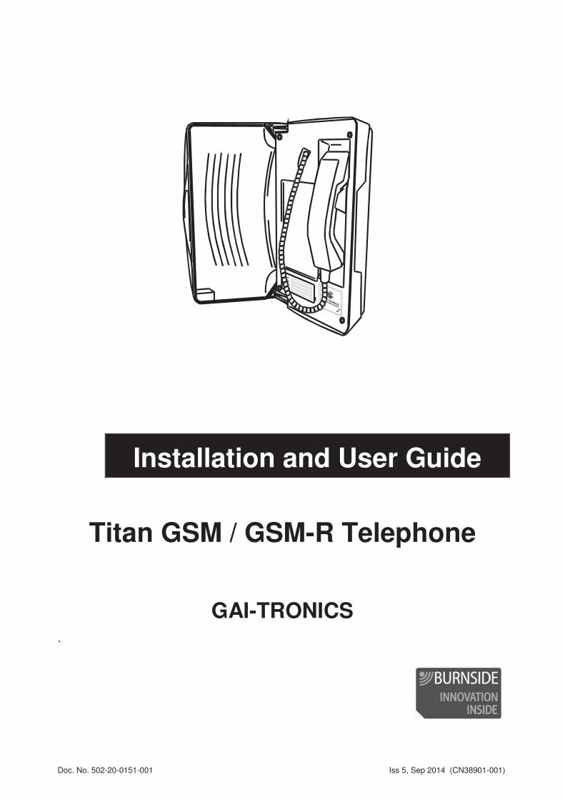
Installation and User Guide
Titan GSM / GSM-R Telephone
GAI-TRONICS .

2 Titan GSM
CONTENTS
1.� Safety and Care Information ....................................................................... 4�
2.� Product Description .................................................................................... 5�
3.� Operation / Testing ..................................................................................... 7�
3.1.� Making Calls ................................................................................. 7�
3.2.� Receiving calls ............................................................................. 7�
3.3.� Last Number Redial ..................................................................... 7�
3.4.� Secrecy (Mute) ............................................................................. 7�
4.� Installation .................................................................................................. 8�
4.1.� Prior to Installation ....................................................................... 8�
4.2.� Important Notes for Installers and Maintainers ............................. 8�
4.3.� Installation overview ..................................................................... 9�
4.4.� Mounting methods and dimensions ............................................ 10�
4.5.� Internal connections ................................................................... 14�
4.6.� Removing the Rear Cover .......................................................... 14�
4.7.� Installing the SIM ........................................................................ 15�
4.8.� Fitting the rear cover .................................................................. 15�
4.9.� Battery connections .................................................................... 18�
4.10.� Connecting the telephone .......................................................... 18�
4.11.� LED indications and operating states ......................................... 20�
4.12.� Switch on and test ...................................................................... 21�
4.13.� Switching the phone off (power down) ....................................... 22�
4.14.� Operating states of the phone .................................................... 22�
5.� Programming, configuration and diagnostics ............................................ 23�
5.1.� Sending Commands by SMS ..................................................... 23�
5.2.� Sending Commands via USB port .............................................. 23�
5.3.� List of Commands (for use with either SMS or USB) ................. 24�
6.� Troubleshooting ........................................................................................ 32�
Titan GSM 3
6.1.� Phone not responding to 1234stat0 request via SMS: ............... 32�
6.2.� ERROR light is permanently ON ................................................ 33�
6.3.� ERROR light flashing Long/Fast ................................................ 33�
6.4.� FUNCTION and ERROR lights flashing Long/Fast .................... 33�
6.5.� FUNCTION and ERROR lights flashing Short/Slow ................... 33�
7.� Maintenance ............................................................................................. 34�
7.1.� Diagnostic check ........................................................................ 34�
7.2.� Batteries ..................................................................................... 34�
7.3.� Cleaning ..................................................................................... 34�
8.� Aftercare ................................................................................................... 35�
9.� Technical Specifications ........................................................................... 36�
10.� Recycling information ............................................................................... 38�
11.� CE Declaration ......................................................................................... 39�
4 Titan GSM
1. Safety and Care Information
� Please read these instructions thoroughly before starting installation. These products must be installed by competent personnel familiar with electrical and telephone installation.
� The spring-loaded door (where fitted) can close sharply. Take care not to trap fingers etc., during installation and use.
� IMPORTANT! This phone, like any wireless phone, operates using radio signals and the wireless network, which cannot guarantee connection in all conditions. Therefore, you should never rely solely upon any wireless phone for essential communications (e.g. medical emergencies).
Remember, to make or receive any calls, the phone must be switched on, appropriately configured and in an area with adequate cellular signal strength. Emergency calls may not be possible on all wireless phone networks or when certain network services or phone features are in use. Check with local cellular service providers. Emergency calls may be made even when a SIM card is not installed (subject to network availability) using the 112 dialling code.
� Operating environment
Make sure that no special regulation is in force that imposes restrictions on the use of mobile phones. Restrictions to mobile phones would also apply to this telephone. Most modern electronic equipment is shielded from radio frequency (RF) signals. However, certain electronic equipment may not be shielded against the RF signals from your phone.
� Pacemakers
Pacemaker manufacturers recommend that a minimum separation of 20 cm (8 inches) be maintained between a handheld wireless phone and a pacemaker. The same restriction should apply to the external antenna of this phone, where fitted. If you have any reason to suspect that interference is taking place, switch off the phone immediately.
� Hearing aids
The phone’s radio signals may interfere with some hearing aids. In such cases move the antenna as far away as practical or consult your hearing aid supplier.
� Other medical devices
Operation of any radio transmitting equipment, including the phone, may interfere with the function of inadequately protected medical devices. Consult a physician or the manufacturer of the medical device to determine if they are adequately shielded from external RF energy or if you have any questions. Switch off your phone in health care facilities when any regulations posted in these areas instruct you to do so. Hospitals or health care facilities may be using equipment that could be sensitive to external RF energy.

Titan GSM 5
� Radio transmission equipment
While GAI-Tronics GSM products are designed to conform to international standards regarding the acceptance of radio frequency interference, certain installation locations may interfere with their proper operation. We recommend that GAI-Tronics GSM equipment is not installed in close proximity to any equipment that generates RF signals (for example, radio transmitters), and is located as far as possible away from it or in a separate room.
� Potentially explosive atmospheres
Do not install the phone or site the antenna in any area with a potentially explosive atmosphere and obey all signs and instructions. Areas with a potentially explosive atmosphere are often but not always clearly marked. They include chemical transfer or storage facilities; vehicles using liquefied petroleum gas (such as propane or butane): areas where the air contains chemicals or particles, such as grain, dust or metal powders.
2. Product Description
This manual describes GSM (cellular) and GSM-R (GSM for rail) versions of the Titan telephone range. Titan is a family of rugged, weather-resistant metal-bodied telephones available with a range of handset types, keypad configurations, colours and enclosures, based around a common faceplate style.
Most Titans are equipped with a heavy-duty spring-loaded door, but models are available with a soft-close door, without door and also as faceplate only, for flush mounting.

6 Titan GSM
Titan doors may be fitted with slamlocks opened by an 8mm square socket key. Other mechanisms may be fitted.
GSM-R versions incorporate a specific GSM-R module, compatible with the GSM-R network exclusive to railway operators, but are identical to GSM versions in all other respects. In this manual, GSM-R is treated as a variant of the GSM product. All features described as relating to “Titan GSM” are available on GSM-R versions, including the ability to roam onto GSM networks if permitted by the SIM.
Models are available with full numeric keypads for manual dialling, with auto-dial buttons for dialling pre-stored numbers from a single button press, or without any buttons (dial on handset lift). Common keypad layouts are shown below.
Titan GSM and GSM-R telephones offer the following key features:
• Vandal resistant handset and cord
• Inductive coupler fitted as standard for hard of hearing
• Robust and weather resistant: IP65
• Range of keypad options
• Large, easy to see tactile buttons
• Programmable auto-dialler functions for dialling pre-stored numbers
• Quad band GSM communication, takes standard 2G SIM card
• GSM-R versions available (Network Rail approved)
• Range of power supply options including solar
• High capacity internal battery giving 10 hours talk time, 250 hours standby
• Remote programming and diagnostics via SMS
• Automatic acoustic path handset testing
Titan GSM 7
• Wall or pole mounting
• Simple installation
For the full list of product features, please see the specifications in section 9 and configuration options in section 5.
3. Operation / Testing
Please note that, following power connection, there will be a delay while the telephone acquires the network before it can make or receive calls.
3.1. Making Calls
To make a call, lift the handset, wait for dial tone, dial required digits (or press required memory button or Last Number Redial where provided) and wait for connection.
When using a memory button, a brief bust of tones is heard to signify that the call has been placed to the pre-programmed number.
If the telephone is set to dial on handset lift, no dial tone is heard prior to the burst of confidence tones.
To end a call, replace the handset in its cradle.
3.2. Receiving calls
To receive a call, lift the handset when ringing is heard.
Note: It is possible to configure the phone to inhibit incoming calls. If so configured, the sounder will not sound, but the phone can still receive SMS commands, acknowledge commands via SMS and communicate via USB.
3.3. Last Number Redial
(15 and 18 button versions only)
Lift the handset, press LR to redial the last dialled number.
3.4. Secrecy (Mute)
(15 and 18 button versions only)
During a call, press and hold the S button to mute the microphone.
8 Titan GSM
4. Installation
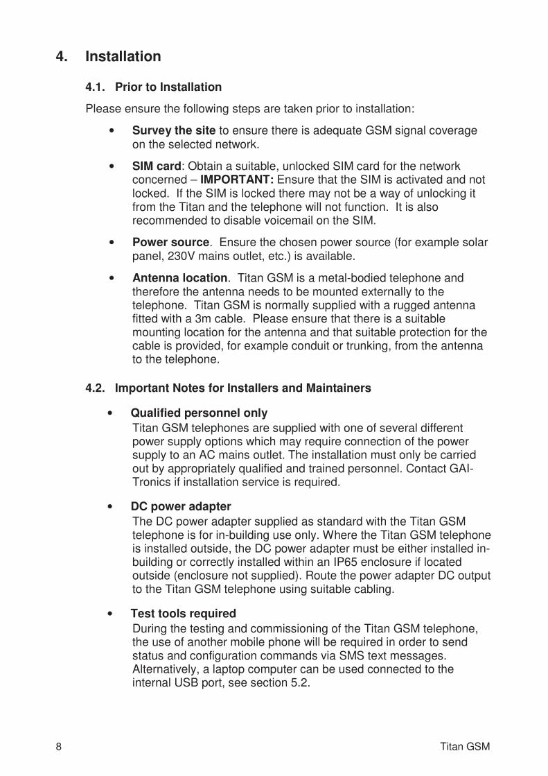
4.1. Prior to Installation
Please ensure the following steps are taken prior to installation:
• Survey the site to ensure there is adequate GSM signal coverage on the selected network.
• SIM card: Obtain a suitable, unlocked SIM card for the network concerned – IMPORTANT: Ensure that the SIM is activated and not locked. If the SIM is locked there may not be a way of unlocking it from the Titan and the telephone will not function. It is also recommended to disable voicemail on the SIM.
• Power source. Ensure the chosen power source (for example solar panel, 230V mains outlet, etc.) is available.
• Antenna location. Titan GSM is a metal-bodied telephone and therefore the antenna needs to be mounted externally to the telephone. Titan GSM is normally supplied with a rugged antenna fitted with a 3m cable. Please ensure that there is a suitable mounting location for the antenna and that suitable protection for the cable is provided, for example conduit or trunking, from the antenna to the telephone.
4.2. Important Notes for Installers and Maintainers
• Qualified personnel only
Titan GSM telephones are supplied with one of several different power supply options which may require connection of the power supply to an AC mains outlet. The installation must only be carried out by appropriately qualified and trained personnel. Contact GAI-Tronics if installation service is required.
• DC power adapter
The DC power adapter supplied as standard with the Titan GSM telephone is for in-building use only. Where the Titan GSM telephone is installed outside, the DC power adapter must be either installed in-building or correctly installed within an IP65 enclosure if located outside (enclosure not supplied). Route the power adapter DC output to the Titan GSM telephone using suitable cabling.
• Test tools required
During the testing and commissioning of the Titan GSM telephone, the use of another mobile phone will be required in order to send status and configuration commands via SMS text messages. Alternatively, a laptop computer can be used connected to the internal USB port, see section 5.2.
Titan GSM 9
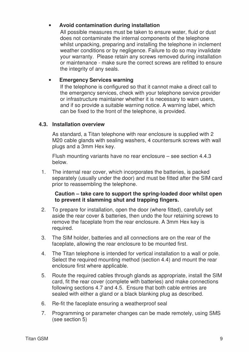
• Avoid contamination during installation
All possible measures must be taken to ensure water, fluid or dust does not contaminate the internal components of the telephone whilst unpacking, preparing and installing the telephone in inclement weather conditions or by negligence. Failure to do so may invalidate your warranty. Please retain any screws removed during installation or maintenance - make sure the correct screws are refitted to ensure the integrity of any seals.
• Emergency Services warning
If the telephone is configured so that it cannot make a direct call to the emergency services, check with your telephone service provider or infrastructure maintainer whether it is necessary to warn users, and if so provide a suitable warning notice. A warning label, which can be fixed to the front of the telephone, is provided.
4.3. Installation overview
As standard, a Titan telephone with rear enclosure is supplied with 2 M20 cable glands with sealing washers, 4 countersunk screws with wall plugs and a 3mm Hex key.
Flush mounting variants have no rear enclosure – see section 4.4.3 below.
1. The internal rear cover, which incorporates the batteries, is packed separately (usually under the door) and must be fitted after the SIM card prior to reassembling the telephone.
Caution – take care to support the spring-loaded door whilst open to prevent it slamming shut and trapping fingers.
2. To prepare for installation, open the door (where fitted), carefully set aside the rear cover & batteries, then undo the four retaining screws to remove the faceplate from the rear enclosure. A 3mm Hex key is required.
3. The SIM holder, batteries and all connections are on the rear of the faceplate, allowing the rear enclosure to be mounted first.
4. The Titan telephone is intended for vertical installation to a wall or pole. Select the required mounting method (section 4.4) and mount the rear enclosure first where applicable.
5. Route the required cables through glands as appropriate, install the SIM card, fit the rear cover (complete with batteries) and make connections following sections 4.7 and 4.5. Ensure that both cable entries are sealed with either a gland or a black blanking plug as described.
6. Re-fit the faceplate ensuring a weatherproof seal
7. Programming or parameter changes can be made remotely, using SMS (see section 5)
10 Titan GSM
8. Test the operation of the telephone (section 3). Installation is now complete.
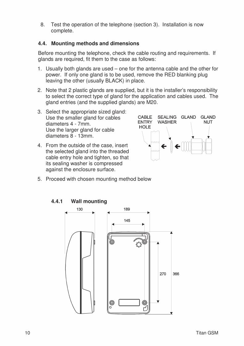
4.4. Mounting methods and dimensions
Before mounting the telephone, check the cable routing and requirements. If glands are required, fit them to the case as follows:
1. Usually both glands are used – one for the antenna cable and the other for power. If only one gland is to be used, remove the RED blanking plug leaving the other (usually BLACK) in place.
2. Note that 2 plastic glands are supplied, but it is the installer’s responsibility to select the correct type of gland for the application and cables used. The gland entries (and the supplied glands) are M20.
3. Select the appropriate sized gland: Use the smaller gland for cables diameters 4 - 7mm. Use the larger gland for cable diameters 8 - 13mm.
4. From the outside of the case, insert the selected gland into the threaded cable entry hole and tighten, so that its sealing washer is compressed against the enclosure surface.
5. Proceed with chosen mounting method below
4.4.1 Wall mounting
Titan GSM 11
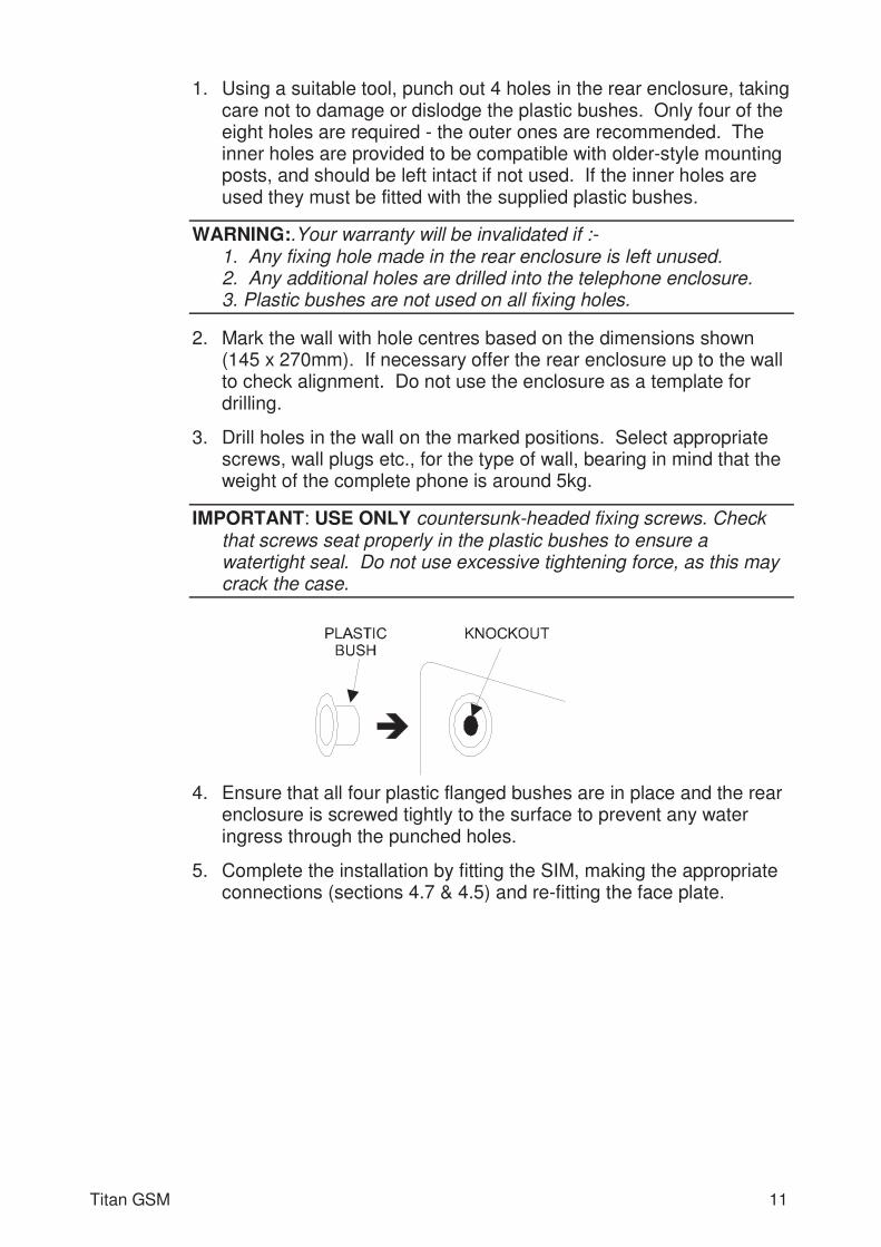
1. Using a suitable tool, punch out 4 holes in the rear enclosure, taking care not to damage or dislodge the plastic bushes. Only four of the eight holes are required - the outer ones are recommended. The inner holes are provided to be compatible with older-style mounting posts, and should be left intact if not used. If the inner holes are used they must be fitted with the supplied plastic bushes.
WARNING:.Your warranty will be invalidated if :- 1. Any fixing hole made in the rear enclosure is left unused. 2. Any additional holes are drilled into the telephone enclosure. 3. Plastic bushes are not used on all fixing holes.
2. Mark the wall with hole centres based on the dimensions shown (145 x 270mm). If necessary offer the rear enclosure up to the wall to check alignment. Do not use the enclosure as a template for drilling.
3. Drill holes in the wall on the marked positions. Select appropriate screws, wall plugs etc., for the type of wall, bearing in mind that the weight of the complete phone is around 5kg.
IMPORTANT: USE ONLY countersunk-headed fixing screws. Check that screws seat properly in the plastic bushes to ensure a watertight seal. Do not use excessive tightening force, as this may crack the case.
4. Ensure that all four plastic flanged bushes are in place and the rear enclosure is screwed tightly to the surface to prevent any water ingress through the punched holes.
5. Complete the installation by fitting the SIM, making the appropriate connections (sections 4.7 & 4.5) and re-fitting the face plate.
12 Titan GSM
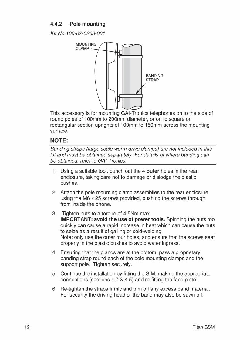
4.4.2 Pole mounting
Kit No 100-02-0208-001
This accessory is for mounting GAI-Tronics telephones on to the side of round poles of 100mm to 200mm diameter, or on to square or rectangular section uprights of 100mm to 150mm across the mounting surface.
NOTE:
Banding straps (large scale worm-drive clamps) are not included in this kit and must be obtained separately. For details of where banding can be obtained, refer to GAI-Tronics.
1. Using a suitable tool, punch out the 4 outer holes in the rear enclosure, taking care not to damage or dislodge the plastic bushes.
2. Attach the pole mounting clamp assemblies to the rear enclosure using the M6 x 25 screws provided, pushing the screws through from inside the phone.
3. Tighten nuts to a torque of 4.5Nm max. IMPORTANT: avoid the use of power tools. Spinning the nuts too quickly can cause a rapid increase in heat which can cause the nuts to seize as a result of galling or cold-welding. Note: only use the outer four holes, and ensure that the screws seat properly in the plastic bushes to avoid water ingress.
4. Ensuring that the glands are at the bottom, pass a proprietary banding strap round each of the pole mounting clamps and the support pole. Tighten securely.
5. Continue the installation by fitting the SIM, making the appropriate connections (sections 4.7 & 4.5) and re-fitting the face plate.
6. Re-tighten the straps firmly and trim off any excess band material. For security the driving head of the band may also be sawn off.
Titan GSM 13
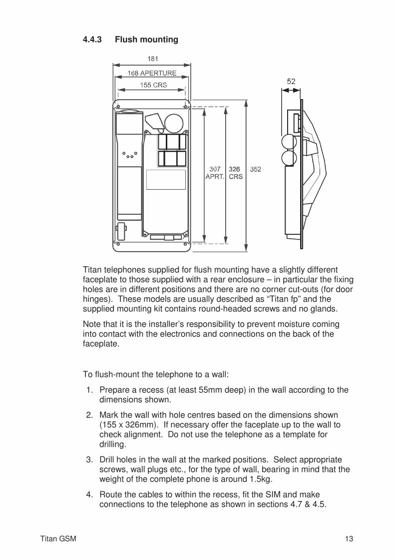
4.4.3 Flush mounting
Titan telephones supplied for flush mounting have a slightly different faceplate to those supplied with a rear enclosure – in particular the fixing holes are in different positions and there are no corner cut-outs (for door hinges). These models are usually described as “Titan fp” and the supplied mounting kit contains round-headed screws and no glands.
Note that it is the installer’s responsibility to prevent moisture coming into contact with the electronics and connections on the back of the faceplate.
To flush-mount the telephone to a wall:
1. Prepare a recess (at least 55mm deep) in the wall according to the dimensions shown.
2. Mark the wall with hole centres based on the dimensions shown (155 x 326mm). If necessary offer the faceplate up to the wall to check alignment. Do not use the telephone as a template for drilling.
3. Drill holes in the wall at the marked positions. Select appropriate screws, wall plugs etc., for the type of wall, bearing in mind that the weight of the complete phone is around 1.5kg.
4. Route the cables to within the recess, fit the SIM and make connections to the telephone as shown in sections 4.7 & 4.5.
14 Titan GSM
5. Secure the telephone to the wall taking care not to trap any wires. Note that the gasket on the rear of the faceplate is intended to make a weather seal when compressed against a smooth surface. Do not rely on this gasket to keep water out if mounting directly to rough surfaces such as brickwork – in these cases use additional sealant around the edges to ensure a weatherproof seal.
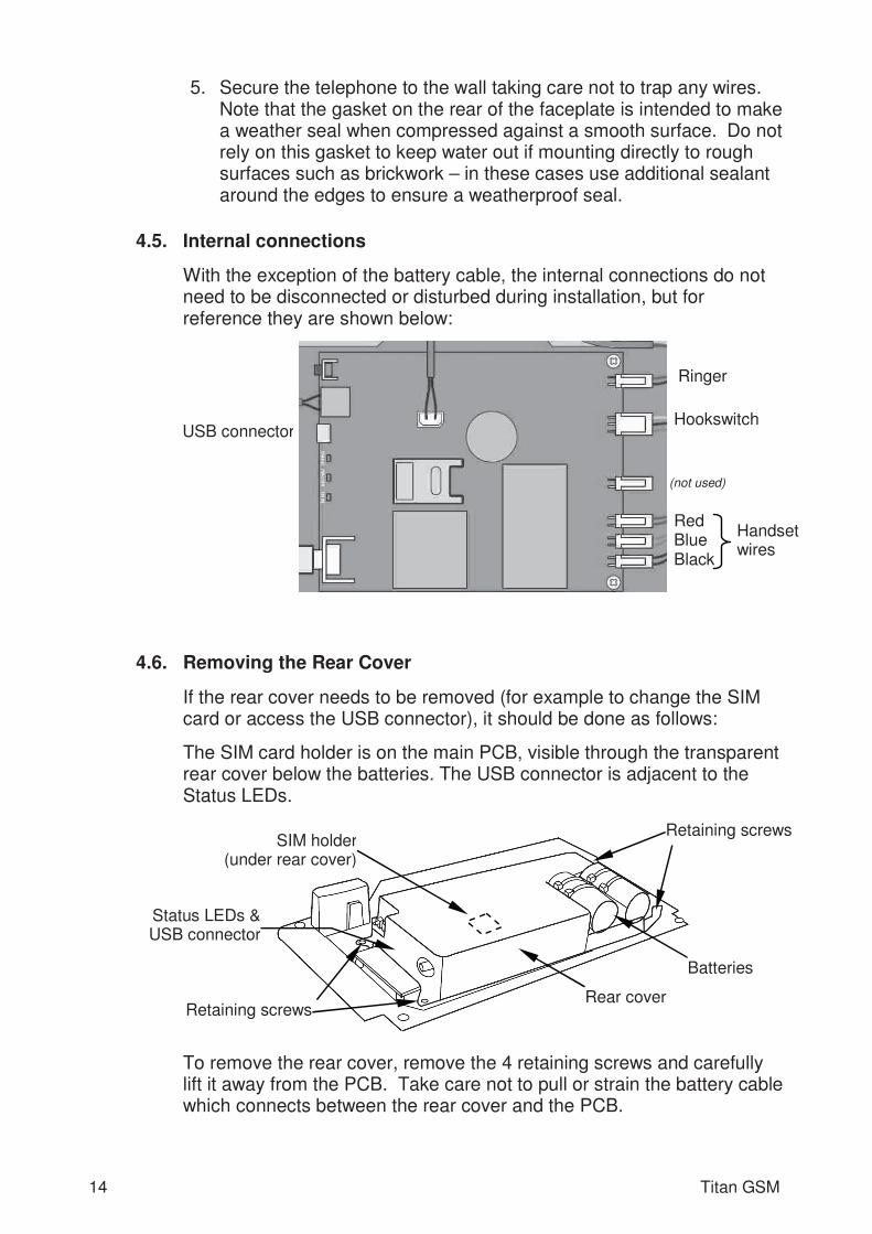
4.5. Internal connections
With the exception of the battery cable, the internal connections do not need to be disconnected or disturbed during installation, but for reference they are shown below:
4.6. Removing the Rear Cover
If the rear cover needs to be removed (for example to change the SIM card or access the USB connector), it should be done as follows:
The SIM card holder is on the main PCB, visible through the transparent rear cover below the batteries. The USB connector is adjacent to the Status LEDs.
To remove the rear cover, remove the 4 retaining screws and carefully lift it away from the PCB. Take care not to pull or strain the battery cable which connects between the rear cover and the PCB.
Rear cover
Batteries
SIM holder (under rear cover)
Retaining screws
Retaining screws
Status LEDs & USB connector
Ringer
Hookswitch
Red Blue Black
Handset wires
USB connector
(not used)
Titan GSM 15
Refit the cover following the instructions in section 4.8.
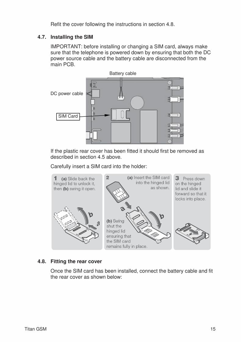
4.7. Installing the SIM
IMPORTANT: before installing or changing a SIM card, always make sure that the telephone is powered down by ensuring that both the DC power source cable and the battery cable are disconnected from the main PCB.
If the plastic rear cover has been fitted it should first be removed as described in section 4.5 above.
Carefully insert a SIM card into the holder:
4.8. Fitting the rear cover
Once the SIM card has been installed, connect the battery cable and fit the rear cover as shown below:
DC power cable
Battery cable
SIM Card

16 Titan GSM
Connect the battery cable
Replace the rear cover taking care not to trap any cables under the side edges, and ensuring that the cables for handset, hookswitch and ringer sit properly in their channels as shown.
HANDSET CABLE
HOOK SWITCH CABLE
RINGER CABLE
(CHANNEL 1)
(CHANNEL 2)
(CHANNEL 3)
(CHANNEL 4)SWITCH CABLE
ADDITIONAL HOOK
OPTIONAL
Secure the rear cover using the 4 M3 x 8 retaining screws provided
Titan GSM 17
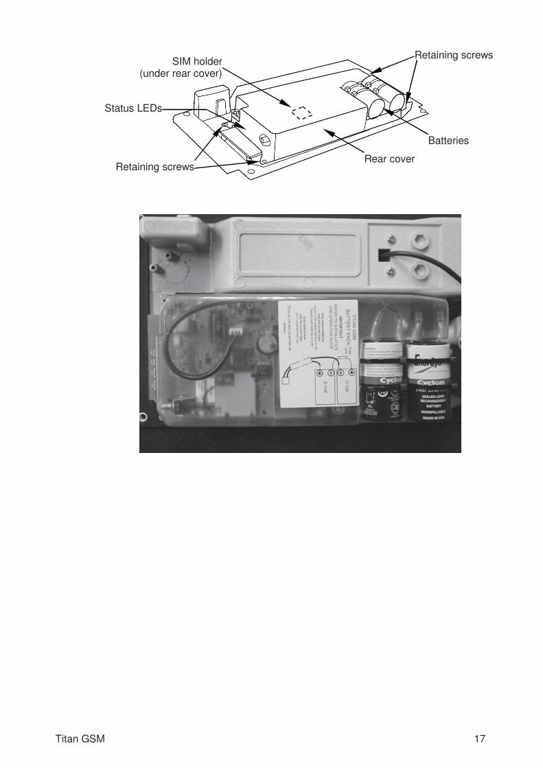
Rear cover
Batteries
SIM holder (under rear cover)
Retaining screws
Retaining screws
Status LEDs
18 Titan GSM
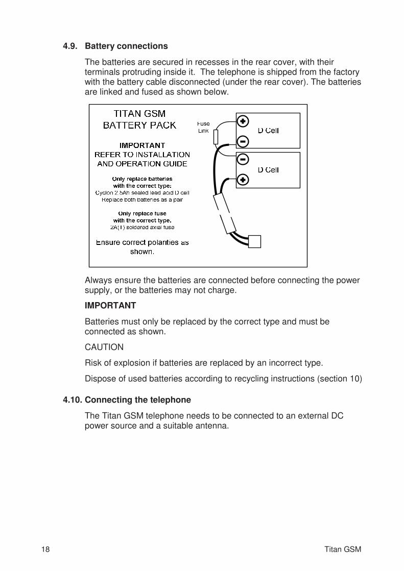
4.9. Battery connections
The batteries are secured in recesses in the rear cover, with their terminals protruding inside it. The telephone is shipped from the factory with the battery cable disconnected (under the rear cover). The batteries are linked and fused as shown below.
Always ensure the batteries are connected before connecting the power supply, or the batteries may not charge.
IMPORTANT
Batteries must only be replaced by the correct type and must be connected as shown.
CAUTION
Risk of explosion if batteries are replaced by an incorrect type.
Dispose of used batteries according to recycling instructions (section 10)
4.10. Connecting the telephone
The Titan GSM telephone needs to be connected to an external DC power source and a suitable antenna.
Titan GSM 19
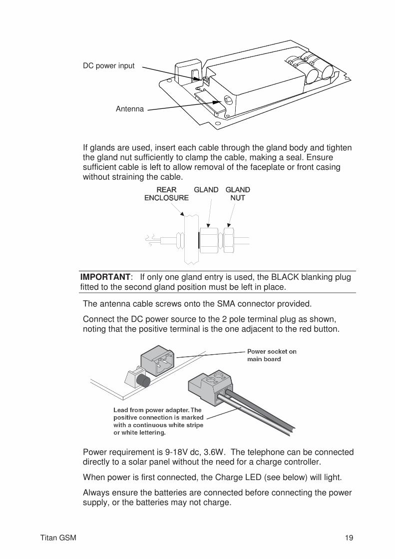
If glands are used, insert each cable through the gland body and tighten the gland nut sufficiently to clamp the cable, making a seal. Ensure sufficient cable is left to allow removal of the faceplate or front casing without straining the cable.
IMPORTANT: If only one gland entry is used, the BLACK blanking plug fitted to the second gland position must be left in place.
The antenna cable screws onto the SMA connector provided.
Connect the DC power source to the 2 pole terminal plug as shown, noting that the positive terminal is the one adjacent to the red button.
Power requirement is 9-18V dc, 3.6W. The telephone can be connected directly to a solar panel without the need for a charge controller.
When power is first connected, the Charge LED (see below) will light.
Always ensure the batteries are connected before connecting the power supply, or the batteries may not charge.
DC power input
Antenna
20 Titan GSM
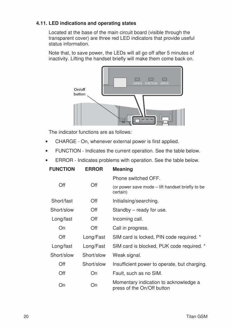
4.11. LED indications and operating states
Located at the base of the main circuit board (visible through the transparent cover) are three red LED indicators that provide useful status information.
Note that, to save power, the LEDs will all go off after 5 minutes of inactivity. Lifting the handset briefly will make them come back on.
The indicator functions are as follows:
• CHARGE - On, whenever external power is first applied.
• FUNCTION - Indicates the current operation. See the table below.
• ERROR - Indicates problems with operation. See the table below.
FUNCTION ERROR Meaning
Off Off
Phone switched OFF.
(or power save mode – lift handset briefly to be certain)
Short/fast Off Initialising/searching.
Short/slow Off Standby – ready for use.
Long/fast Off Incoming call.
On Off Call in progress.
Off Long/Fast SIM card is locked, PIN code required. *
Long/fast Long/Fast SIM card is blocked, PUK code required. *
Short/slow Short/slow Weak signal.
Off Short/slow Insufficient power to operate, but charging.
Off On Fault, such as no SIM.
On On Momentary indication to acknowledge a press of the On/Off button
Titan GSM 21
* Unless the Titan GSM is a version with a full numeric keypad, it is not possible to rectify these faults from the telephone itself. Please ensure that the SIM is not locked (or blocked) prior to use.
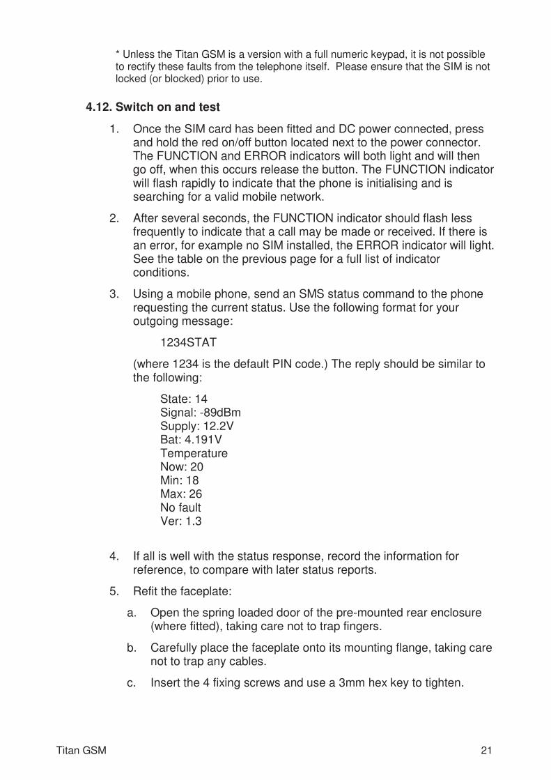
4.12. Switch on and test
1. Once the SIM card has been fitted and DC power connected, press and hold the red on/off button located next to the power connector. The FUNCTION and ERROR indicators will both light and will then go off, when this occurs release the button. The FUNCTION indicator will flash rapidly to indicate that the phone is initialising and is searching for a valid mobile network.
2. After several seconds, the FUNCTION indicator should flash less frequently to indicate that a call may be made or received. If there is an error, for example no SIM installed, the ERROR indicator will light. See the table on the previous page for a full list of indicator conditions.
3. Using a mobile phone, send an SMS status command to the phone requesting the current status. Use the following format for your outgoing message:
1234STAT
(where 1234 is the default PIN code.) The reply should be similar to the following:
State: 14 Signal: -89dBm Supply: 12.2V Bat: 4.191V Temperature Now: 20 Min: 18 Max: 26 No fault Ver: 1.3
4. If all is well with the status response, record the information for reference, to compare with later status reports.
5. Refit the faceplate:
a. Open the spring loaded door of the pre-mounted rear enclosure (where fitted), taking care not to trap fingers.
b. Carefully place the faceplate onto its mounting flange, taking care not to trap any cables.
c. Insert the 4 fixing screws and use a 3mm hex key to tighten.

22 Titan GSM
d. Check that a good weatherproof seal exists between the front and rear casings.
6. Make a call to the phone to ensure the sounder operates. Then make an outgoing call from the phone to an external number. This will only be possible on a phone with a full keypad otherwise auto-dial numbers will first need to be programmed, see section 5.
For many installations, the steps outlined so far will result in a fully functioning phone.
However, the Titan GSM is also highly customisable for many situations. Detailed configuration is made possible by either sending specially formatted SMS messages from another phone or by connecting a computer via the USB port. For details, please see section 5.
4.13. Switching the phone off (power down)
If the phone is to be shipped, stored, or the SIM changed, press and hold the pushbutton until the FUNCTION and ERROR indicators extinguish. The phone will now be in the Off (Charge Only) state.
4.14. Operating states of the phone
Titan GSM has the following operating states:
• On - The phone is fully powered and ready to make and receive calls.
• Charge only - This is the state that the phone will enter when external DC power is applied. If power is removed, the phone will enter the “Off” state.
• Off - This is the state in which the phone is shipped from the factory to prevent battery drain in transit and storage.
The SIM card should only be fitted or removed if the telephone is in the OFF state.
If the phone is “Off” and has sufficient battery power or is in “Charge only” mode, pressing the on/off pushbutton will put the phone into the “On” state.
The “On” state is remembered, regardless of the amount of charge in the battery or the availability of DC supply.
If the ERROR indicator is flashing Short/Slow, leave the external DC power connected to fully charge the battery, or at least until the ERROR indicator stops flashing.
Note: to fully charge the battery may take in excess of 5 hours depending on the current charge state of the battery.
Titan GSM 23
If the phone is “On” and the battery charge becomes exhausted, the phone will turn off. Once the external DC supply is restored, the phone will automatically enter the “On” state and also start charging the battery.
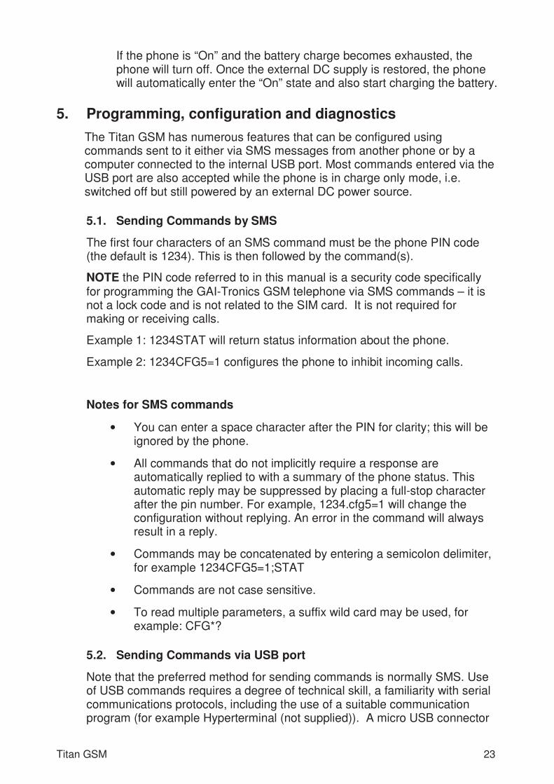
5. Programming, configuration and diagnostics
The Titan GSM has numerous features that can be configured using commands sent to it either via SMS messages from another phone or by a computer connected to the internal USB port. Most commands entered via the USB port are also accepted while the phone is in charge only mode, i.e. switched off but still powered by an external DC power source.
5.1. Sending Commands by SMS
The first four characters of an SMS command must be the phone PIN code (the default is 1234). This is then followed by the command(s).
NOTE the PIN code referred to in this manual is a security code specifically for programming the GAI-Tronics GSM telephone via SMS commands – it is not a lock code and is not related to the SIM card. It is not required for making or receiving calls.
Example 1: 1234STAT will return status information about the phone.
Example 2: 1234CFG5=1 configures the phone to inhibit incoming calls.
Notes for SMS commands
• You can enter a space character after the PIN for clarity; this will be ignored by the phone.
• All commands that do not implicitly require a response are automatically replied to with a summary of the phone status. This automatic reply may be suppressed by placing a full-stop character after the pin number. For example, 1234.cfg5=1 will change the configuration without replying. An error in the command will always result in a reply.
• Commands may be concatenated by entering a semicolon delimiter, for example 1234CFG5=1;STAT
• Commands are not case sensitive.
• To read multiple parameters, a suffix wild card may be used, for example: CFG*?
5.2. Sending Commands via USB port
Note that the preferred method for sending commands is normally SMS. Use of USB commands requires a degree of technical skill, a familiarity with serial communications protocols, including the use of a suitable communication program (for example Hyperterminal (not supplied)). A micro USB connector

24 Titan GSM
lead (not supplied) will be required to connect the phone to a suitable USB port.
IMPORTANT: Before connecting the Titan GSM to a computer via USB, ensure the Silicon Labs USB device driver software has been downloaded from
www.silabs.com/products/mcu/pages/usbtouartbridgevcpdrivers.aspx
Ensure that the correct version for your operating system is installed.
Configure a suitable communication program to connect to the virtual COM port assigned to the USB driver. Connect at 115200bps 8/N/1.
The first three characters of a USB programming command must be AT! This is then followed by the command(s).
Example 1: AT!STAT<cr> where <cr> is a carriage return/enter
Example 2: AT!CFG5=1<cr> sets the phone to inhibit incoming calls.
Notes for USB commands
• The AT! Commands are specific to this product range and are not related to the Hayes™ AT command set
• Commands may be concatenated by entering a semicolon delimiter, for example AT!CFG5=1;STAT<cr>
5.3. List of Commands (for use with either SMS or USB)
STATn Returns the status of the phone. If n is omitted, it is interpreted as zero.
STAT (or STAT0) for general status, useful during installation:
State: s (phone state, see table below) Signal: -89dBm Supply: 12.2V Bat: 4.191V Temperature – (in degrees Celsius) Now: 20 Min: 18 Max: 26 No fault/Fault Ver: 1.0
Note that normally the signal should be between -90 and -50, the supply should be between 9 and 18V, and the Battery should be between 4.00 and 4.40V.
If a fault is shown, send stat1 for more details.
State (s) value returned from a STAT0 command:
Value Meaning

Titan GSM 25
1 Outside operating temperature limits. 2 Charge only. 3 Insufficient power to operate in solar charge
mode. 4 Error condition, communication failure with
wireless module. 5 Phone is initialising. 6 Checking SIM present. 7 No SIM installed. 8 Checking SIM lock. 9 Waiting for SIM PIN. 10 Waiting for SIM PUK. 11 Post SIM unlock initialisation phase. 12 Settle time for reading SMS memory. 13 Flushing SMS memory. 14 Ready for call (always in this state when
replying via SMS)
STAT1 for information about faults:
Hook: On/Off Power break: No/Yes Loop: Pass/Fail Acoustic loop: Pass/Fail Keyboard: Pass/x stuck on Battery: OK/Fault
Explanation of stat1 fault results: Hook: On = normal, Off = the handset is off its cradle Power break: No = normal, Yes = power has been interrupted Loop: Pass = normal, Fail = the handset integrity loop is
broken, meaning that the handset has been detached or vandalised
Acoustic loop: Pass = normal, Fail = either the microphone or earpiece is not responding, ie the handset is faulty or blocked.
Keyboard: Pass = normal, x stuck on = a pushbutton is permanently stuck in, preventing anyone from using the pushbuttons.
Battery: OK = normal, Fault = the battery is not holding charge properly, even if it has the correct voltage.
STAT2 returns all status information in a single string of text, intended to be read by a computer. See the paragraph on CFG9 for explanation.
26 Titan GSM
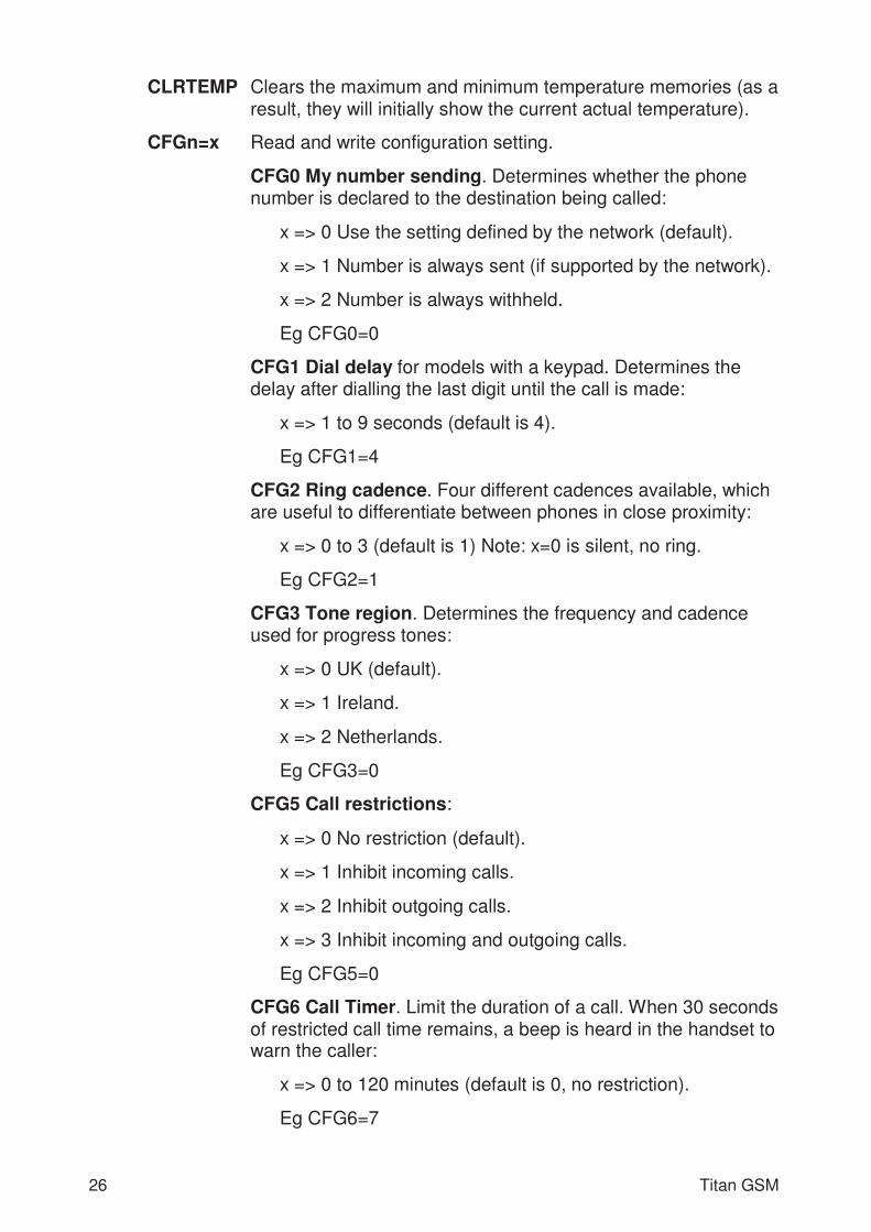
CLRTEMP Clears the maximum and minimum temperature memories (as a result, they will initially show the current actual temperature).
CFGn=x Read and write configuration setting.
CFG0 My number sending. Determines whether the phone number is declared to the destination being called:
x => 0 Use the setting defined by the network (default).
x => 1 Number is always sent (if supported by the network).
x => 2 Number is always withheld.
Eg CFG0=0
CFG1 Dial delay for models with a keypad. Determines the delay after dialling the last digit until the call is made:
x => 1 to 9 seconds (default is 4).
Eg CFG1=4
CFG2 Ring cadence. Four different cadences available, which are useful to differentiate between phones in close proximity:
x => 0 to 3 (default is 1) Note: x=0 is silent, no ring.
Eg CFG2=1
CFG3 Tone region. Determines the frequency and cadence used for progress tones:
x => 0 UK (default).
x => 1 Ireland.
x => 2 Netherlands.
Eg CFG3=0
CFG5 Call restrictions:
x => 0 No restriction (default).
x => 1 Inhibit incoming calls.
x => 2 Inhibit outgoing calls.
x => 3 Inhibit incoming and outgoing calls.
Eg CFG5=0
CFG6 Call Timer. Limit the duration of a call. When 30 seconds of restricted call time remains, a beep is heard in the handset to warn the caller:
x => 0 to 120 minutes (default is 0, no restriction).
Eg CFG6=7
Titan GSM 27
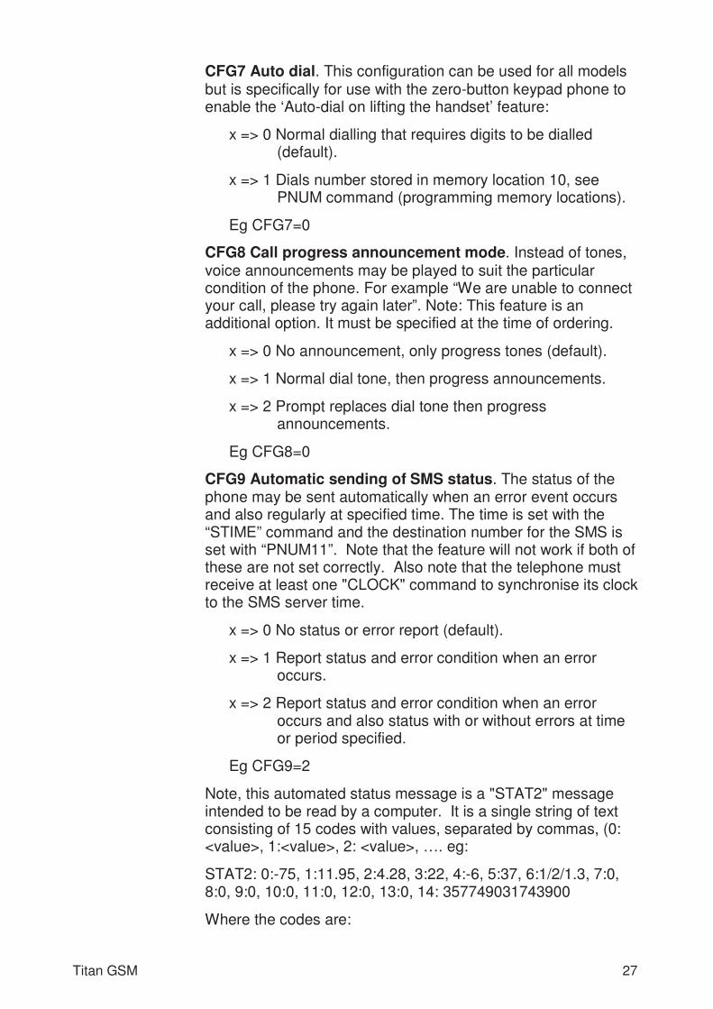
CFG7 Auto dial. This configuration can be used for all models but is specifically for use with the zero-button keypad phone to enable the ‘Auto-dial on lifting the handset’ feature:
x => 0 Normal dialling that requires digits to be dialled (default).
x => 1 Dials number stored in memory location 10, see PNUM command (programming memory locations).
Eg CFG7=0
CFG8 Call progress announcement mode. Instead of tones, voice announcements may be played to suit the particular condition of the phone. For example “We are unable to connect your call, please try again later”. Note: This feature is an additional option. It must be specified at the time of ordering.
x => 0 No announcement, only progress tones (default).
x => 1 Normal dial tone, then progress announcements.
x => 2 Prompt replaces dial tone then progress announcements.
Eg CFG8=0
CFG9 Automatic sending of SMS status. The status of the phone may be sent automatically when an error event occurs and also regularly at specified time. The time is set with the “STIME” command and the destination number for the SMS is set with “PNUM11”. Note that the feature will not work if both of these are not set correctly. Also note that the telephone must receive at least one "CLOCK" command to synchronise its clock to the SMS server time.
x => 0 No status or error report (default).
x => 1 Report status and error condition when an error occurs.
x => 2 Report status and error condition when an error occurs and also status with or without errors at time or period specified.
Eg CFG9=2
Note, this automated status message is a "STAT2" message intended to be read by a computer. It is a single string of text consisting of 15 codes with values, separated by commas, (0: <value>, 1:<value>, 2: <value>, …. eg:
STAT2: 0:-75, 1:11.95, 2:4.28, 3:22, 4:-6, 5:37, 6:1/2/1.3, 7:0, 8:0, 9:0, 10:0, 11:0, 12:0, 13:0, 14: 357749031743900
Where the codes are:

28 Titan GSM
0 = Signal in dBm (eg -75)
1 = Supply voltage in volts (eg 11.95)
2 = Battery voltage (eg 4.28)
3 = Temperature now (in Celsius) (eg 22)
4 = Minimum temperature recorded (eg -6)
5= Maximum temperature recorded (eg 37)
6 = Model/HW ver./Firmware ver. (eg 1/2/1.3)
7 = Hook switch state (0 is on-hook, 1 is off-hook)
8 = Power break (0 for none, otherwise 1. Cleared on read)
9 = Handset hardware loop state (0 for OK, 1 for fault)
10 = Acoustic loop test (0 for pass, 1 for fail, 2 for test not applicable)
11 = Keyboard (0 is OK, 1:n for fail where n is the key number)
12 = Call state (0 for idle, 1 for call in progress,)
13 = Battery state (0 for OK, 1 for fault)
14 = IMEI (eg 357749031743900)
Note that faults are shown in the codes between 7 and 13.
For a more human-readable summary of faults, use STAT1 if required.
The error condition(s) which initiate(s) automatic sending of status are selected with CFG22
CFG12 Maximum dialled number length. The maximum number of digits to be accepted can be defined.
x => 1 to 20 (default is 20).
Eg CFG12=20
CFG15 Activate relay for ring indication. One of the relays may be used to activate an external sounder. The relays switch at selected ring cadence.
x => 0 No action (default).
x => 1 Use relay 1 with ring cadence.
x => 2 Use relay 1 continuously.
x => 3 Use relay 2 with ring cadence.
x => 4 Use relay 2 continuously.
Titan GSM 29
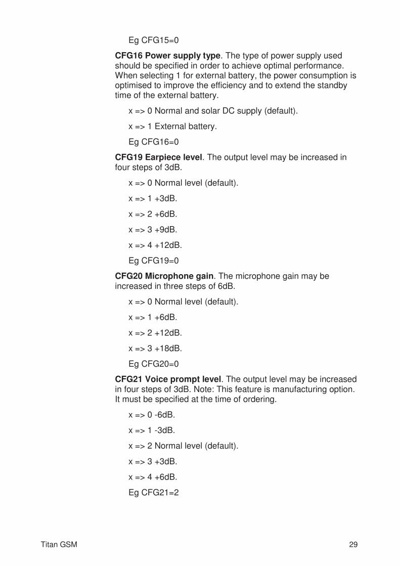
Eg CFG15=0
CFG16 Power supply type. The type of power supply used should be specified in order to achieve optimal performance. When selecting 1 for external battery, the power consumption is optimised to improve the efficiency and to extend the standby time of the external battery.
x => 0 Normal and solar DC supply (default).
x => 1 External battery.
Eg CFG16=0
CFG19 Earpiece level. The output level may be increased in four steps of 3dB.
x => 0 Normal level (default).
x => 1 +3dB.
x => 2 +6dB.
x => 3 +9dB.
x => 4 +12dB.
Eg CFG19=0
CFG20 Microphone gain. The microphone gain may be increased in three steps of 6dB.
x => 0 Normal level (default).
x => 1 +6dB.
x => 2 +12dB.
x => 3 +18dB.
Eg CFG20=0
CFG21 Voice prompt level. The output level may be increased in four steps of 3dB. Note: This feature is manufacturing option. It must be specified at the time of ordering.
x => 0 -6dB.
x => 1 -3dB.
x => 2 Normal level (default).
x => 3 +3dB.
x => 4 +6dB.
Eg CFG21=2

30 Titan GSM
CFG22 Error conditions to report.
The value of CFG22 sets which faults will report when CFG9=1.
Fault Weight Default Bit
Handset loop failure
1 1 0
Stuck key 2 1 1
Battery failure 4 1 2
Low battery 8 1 3
Not used 16 1 4
Power break 32 0 5
The value is set by adding together the weights of the required functions. For example to enable fault reporting on handset loop and battery failure only (weights 1 & 4) the command would be CFG22=5.
The default is 31 (all errors report except power break). To report all errors, CFG22 should be set to 63.
Notes:
• A stuck key is determined by a key being held down for in excess of one minute.
• Battery failure is determined by an abnormal rate of change of the battery voltage when subjected to charge current.
• Low battery is when there is less than 20% charge remaining.
• Power break is when power is lost (when previously externally powered).
• Error states remain until cleared with CLRFAULT or INIT commands.
AUTO Shorthand way of combining PNUM10=n and CFG7=1, where n is the phone number. This is used for setting the phone number to be automatically called when lifting the handset, on the zero button keypad version. Example: auto=01283500400
CLOCK Only via SMS, sets the clock to the time recorded in the SMS delivery from the mobile network. For setting via USB, see ETSI +CCLK
CLRFAULT Clears any fault condition without restarting the phone
Titan GSM 31
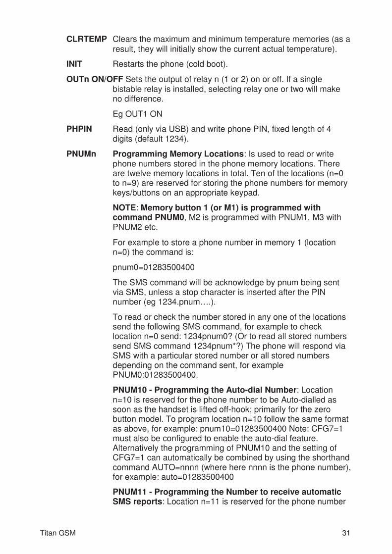
CLRTEMP Clears the maximum and minimum temperature memories (as a result, they will initially show the current actual temperature).
INIT Restarts the phone (cold boot).
OUTn ON/OFF Sets the output of relay n (1 or 2) on or off. If a single bistable relay is installed, selecting relay one or two will make no difference.
Eg OUT1 ON
PHPIN Read (only via USB) and write phone PIN, fixed length of 4 digits (default 1234).
PNUMn Programming Memory Locations: Is used to read or write phone numbers stored in the phone memory locations. There are twelve memory locations in total. Ten of the locations (n=0 to n=9) are reserved for storing the phone numbers for memory keys/buttons on an appropriate keypad.
NOTE: Memory button 1 (or M1) is programmed with command PNUM0, M2 is programmed with PNUM1, M3 with PNUM2 etc.
For example to store a phone number in memory 1 (location n=0) the command is:
pnum0=01283500400
The SMS command will be acknowledge by pnum being sent via SMS, unless a stop character is inserted after the PIN number (eg 1234.pnum….).
To read or check the number stored in any one of the locations send the following SMS command, for example to check location n=0 send: 1234pnum0? (Or to read all stored numbers send SMS command 1234pnum*?) The phone will respond via SMS with a particular stored number or all stored numbers depending on the command sent, for example PNUM0:01283500400.
PNUM10 - Programming the Auto-dial Number: Location n=10 is reserved for the phone number to be Auto-dialled as soon as the handset is lifted off-hook; primarily for the zero button model. To program location n=10 follow the same format as above, for example: pnum10=01283500400 Note: CFG7=1 must also be configured to enable the auto-dial feature. Alternatively the programming of PNUM10 and the setting of CFG7=1 can automatically be combined by using the shorthand command AUTO=nnnn (where here nnnn is the phone number), for example: auto=01283500400
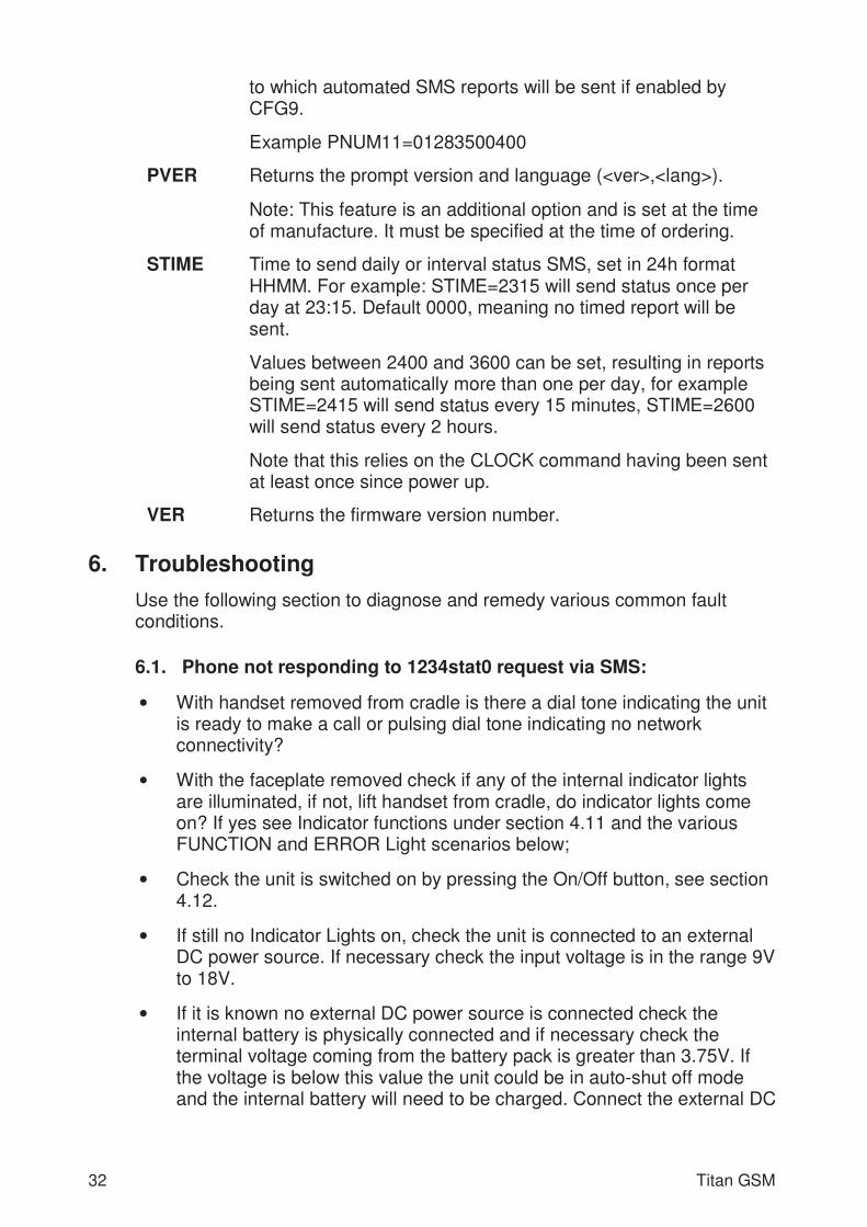
PNUM11 - Programming the Number to receive automatic SMS reports: Location n=11 is reserved for the phone number
32 Titan GSM
to which automated SMS reports will be sent if enabled by CFG9.
Example PNUM11=01283500400
PVER Returns the prompt version and language (<ver>,<lang>).
Note: This feature is an additional option and is set at the time of manufacture. It must be specified at the time of ordering.
STIME Time to send daily or interval status SMS, set in 24h format HHMM. For example: STIME=2315 will send status once per day at 23:15. Default 0000, meaning no timed report will be sent.
Values between 2400 and 3600 can be set, resulting in reports being sent automatically more than one per day, for example STIME=2415 will send status every 15 minutes, STIME=2600 will send status every 2 hours.
Note that this relies on the CLOCK command having been sent at least once since power up.
VER Returns the firmware version number.
6. Troubleshooting
Use the following section to diagnose and remedy various common fault conditions.
6.1. Phone not responding to 1234stat0 request via SMS:
• With handset removed from cradle is there a dial tone indicating the unit is ready to make a call or pulsing dial tone indicating no network connectivity?
• With the faceplate removed check if any of the internal indicator lights are illuminated, if not, lift handset from cradle, do indicator lights come on? If yes see Indicator functions under section 4.11 and the various FUNCTION and ERROR Light scenarios below;
• Check the unit is switched on by pressing the On/Off button, see section 4.12.
• If still no Indicator Lights on, check the unit is connected to an external DC power source. If necessary check the input voltage is in the range 9V to 18V.
• If it is known no external DC power source is connected check the internal battery is physically connected and if necessary check the terminal voltage coming from the battery pack is greater than 3.75V. If the voltage is below this value the unit could be in auto-shut off mode and the internal battery will need to be charged. Connect the external DC
Titan GSM 33
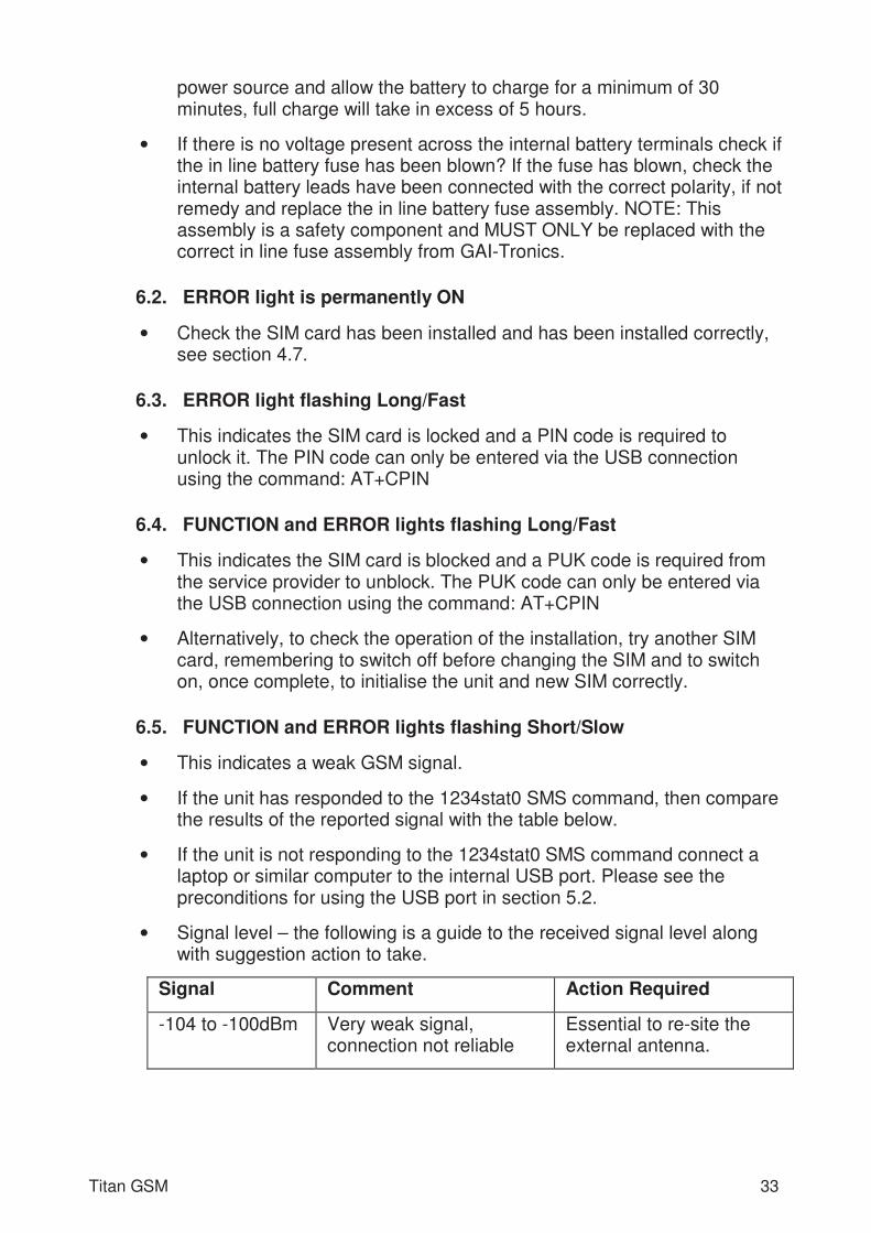
power source and allow the battery to charge for a minimum of 30 minutes, full charge will take in excess of 5 hours.
• If there is no voltage present across the internal battery terminals check if the in line battery fuse has been blown? If the fuse has blown, check the internal battery leads have been connected with the correct polarity, if not remedy and replace the in line battery fuse assembly. NOTE: This assembly is a safety component and MUST ONLY be replaced with the correct in line fuse assembly from GAI-Tronics.
6.2. ERROR light is permanently ON
• Check the SIM card has been installed and has been installed correctly, see section 4.7.
6.3. ERROR light flashing Long/Fast
• This indicates the SIM card is locked and a PIN code is required to unlock it. The PIN code can only be entered via the USB connection using the command: AT+CPIN
6.4. FUNCTION and ERROR lights flashing Long/Fast
• This indicates the SIM card is blocked and a PUK code is required from the service provider to unblock. The PUK code can only be entered via the USB connection using the command: AT+CPIN
• Alternatively, to check the operation of the installation, try another SIM card, remembering to switch off before changing the SIM and to switch on, once complete, to initialise the unit and new SIM correctly.
6.5. FUNCTION and ERROR lights flashing Short/Slow
• This indicates a weak GSM signal.
• If the unit has responded to the 1234stat0 SMS command, then compare the results of the reported signal with the table below.
• If the unit is not responding to the 1234stat0 SMS command connect a laptop or similar computer to the internal USB port. Please see the preconditions for using the USB port in section 5.2.
• Signal level – the following is a guide to the received signal level along with suggestion action to take.
Signal Comment Action Required
-104 to -100dBm Very weak signal, connection not reliable
Essential to re-site the external antenna.

34 Titan GSM
Signal Comment Action Required
-99 to -90dBm Poor signal, connection should be reliable but speech may be subject to interruption due to signal fading effects
Performance should be improved by re-siting the external antenna
-89 to -70dBm Good signal condition None specifically, re-siting antenna may give further improvement
-60 to -50dBm Very good signal condition
None
7. Maintenance
Titan GSM requires very little maintenance in normal use, but please take note of the following to ensure that the telephone is kept in good working order:
7.1. Diagnostic check
Perform a regular status check by sending an SMS:
1234stat
Where 1234 is the PIN code.
The telephone will send back comprehensive information to assist maintenance and repair. Compare this information with that recorded earlier to check if anything has changed that might indicate a problem.
7.2. Batteries
The batteries fitted to Titan GSM are long-life, high performance batteries with an expected service life of 10 years under normal use.
They must only be replaced by the correct type, ordered from GAI-Tronics, and must always be replaced as a pair.
They are each held in place with 2 cable ties, and must be connected and linked by a fuse as shown in section 4.9.
7.3. Cleaning
7.3.1 General
For normal cleaning we recommend "Virosol", manufactured by Clover products.

Titan GSM 35
Carefully follow manufacturer's instructions for storage, handling and use.
7.3.2 Anti graffiti coating
Where polyurethane anti-graffiti coating or paint has been specified (as an option), it can be cleaned using Methylated Spirits or Methyl Isobutyl Ketone. Other cleaners can be used but should be tested on a small area first.
8. Aftercare
The purchase of your GAI-Tronics product does not end our commitment to you. In addition to our warranty obligations, GAI-Tronics are able to offer various levels of maintenance packages, installation and commissioning packages and technical support, from ad-hoc repairs to full maintenance contracts. By choosing GAI-Tronics as your aftercare provider you are ensured of manufacturer expertise and ISO 9001-certified quality control standards throughout the life of the product. We can also supply a full range of accessories including mounting posts, beacons and high-volume sounders. Contact GAI-Tronics for details. www.gai-tronics.co.uk
36 Titan GSM
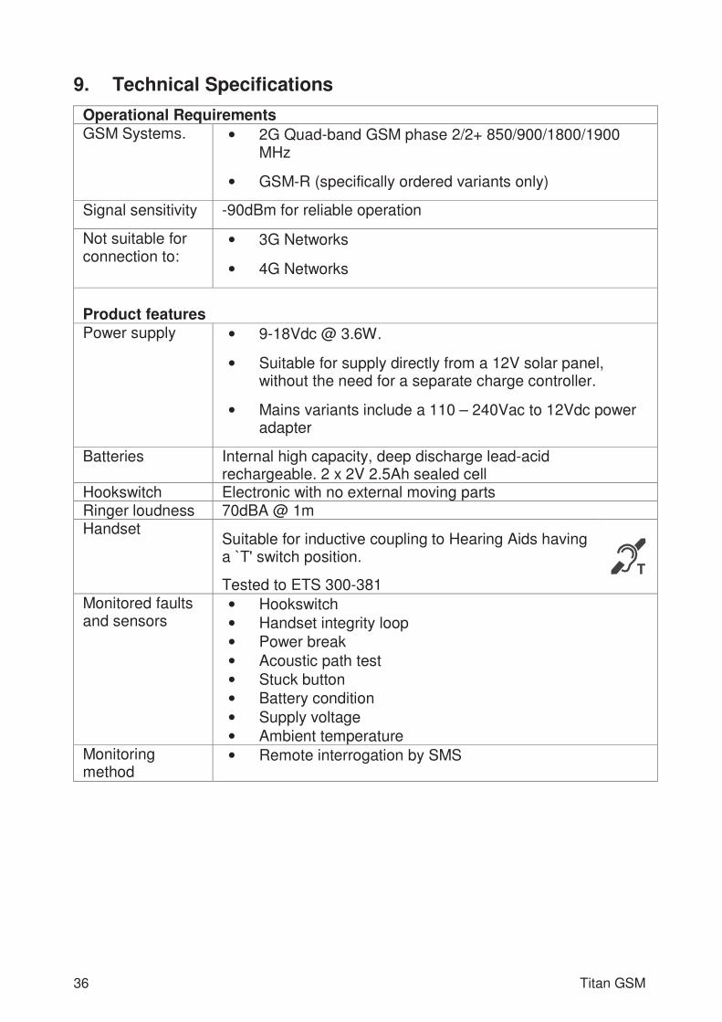
9. Technical Specifications
Operational Requirements
GSM Systems. • 2G Quad-band GSM phase 2/2+ 850/900/1800/1900 MHz
• GSM-R (specifically ordered variants only)
Signal sensitivity -90dBm for reliable operation
Not suitable for connection to:
• 3G Networks
• 4G Networks
Product features
Power supply • 9-18Vdc @ 3.6W.
• Suitable for supply directly from a 12V solar panel, without the need for a separate charge controller.
• Mains variants include a 110 – 240Vac to 12Vdc power adapter
Batteries Internal high capacity, deep discharge lead-acid rechargeable. 2 x 2V 2.5Ah sealed cell
Hookswitch Electronic with no external moving parts Ringer loudness 70dBA @ 1m Handset
Suitable for inductive coupling to Hearing Aids having a `T' switch position.
Tested to ETS 300-381
Monitored faults and sensors
• Hookswitch
• Handset integrity loop
• Power break
• Acoustic path test
• Stuck button
• Battery condition
• Supply voltage
• Ambient temperature Monitoring method
• Remote interrogation by SMS
Titan GSM 37
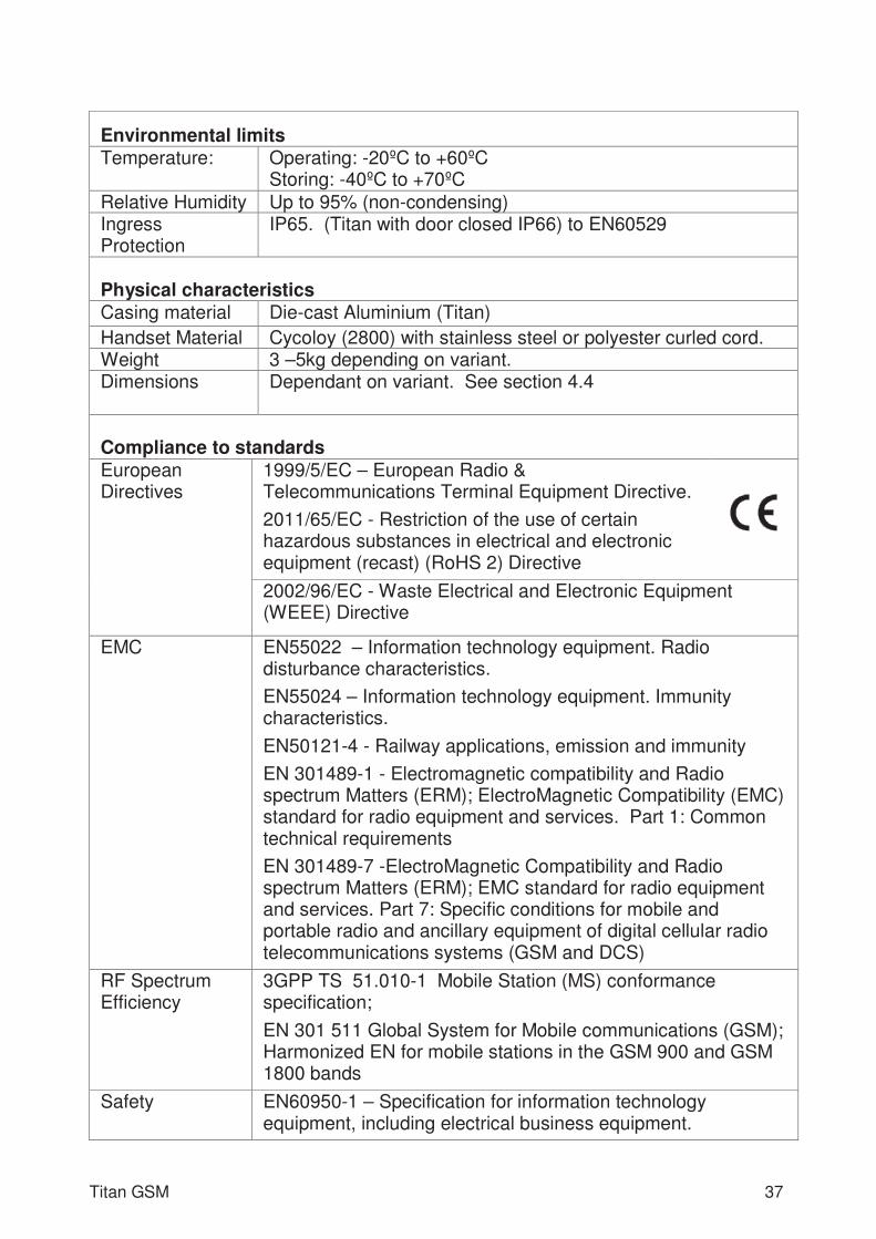
Environmental limits
Temperature: Operating: -20ºC to +60ºC Storing: -40ºC to +70ºC
Relative Humidity Up to 95% (non-condensing) Ingress Protection
IP65. (Titan with door closed IP66) to EN60529
Physical characteristics
Casing material Die-cast Aluminium (Titan)
Handset Material Cycoloy (2800) with stainless steel or polyester curled cord. Weight 3 –5kg depending on variant. Dimensions Dependant on variant. See section 4.4
Compliance to standards
European Directives
1999/5/EC – European Radio & Telecommunications Terminal Equipment Directive.
2011/65/EC - Restriction of the use of certain hazardous substances in electrical and electronic equipment (recast) (RoHS 2) Directive
2002/96/EC - Waste Electrical and Electronic Equipment (WEEE) Directive
EMC EN55022 – Information technology equipment. Radio disturbance characteristics.
EN55024 – Information technology equipment. Immunity characteristics.
EN50121-4 - Railway applications, emission and immunity
EN 301489-1 - Electromagnetic compatibility and Radio spectrum Matters (ERM); ElectroMagnetic Compatibility (EMC) standard for radio equipment and services. Part 1: Common technical requirements
EN 301489-7 -ElectroMagnetic Compatibility and Radio spectrum Matters (ERM); EMC standard for radio equipment and services. Part 7: Specific conditions for mobile and portable radio and ancillary equipment of digital cellular radio telecommunications systems (GSM and DCS)
RF Spectrum Efficiency
3GPP TS 51.010-1 Mobile Station (MS) conformance specification;
EN 301 511 Global System for Mobile communications (GSM); Harmonized EN for mobile stations in the GSM 900 and GSM 1800 bands
Safety EN60950-1 – Specification for information technology equipment, including electrical business equipment.
38 Titan GSM
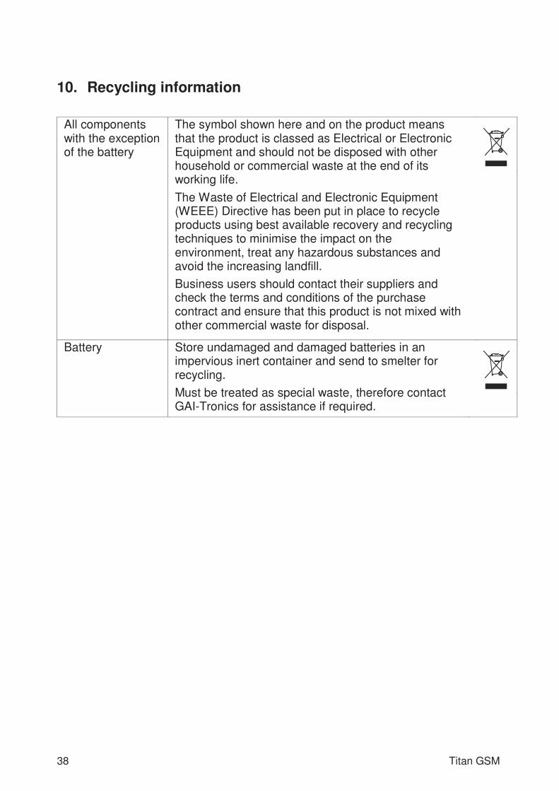
10. Recycling information
All components with the exception of the battery
The symbol shown here and on the product means that the product is classed as Electrical or Electronic Equipment and should not be disposed with other household or commercial waste at the end of its working life.
The Waste of Electrical and Electronic Equipment (WEEE) Directive has been put in place to recycle products using best available recovery and recycling techniques to minimise the impact on the environment, treat any hazardous substances and avoid the increasing landfill.
Business users should contact their suppliers and check the terms and conditions of the purchase contract and ensure that this product is not mixed with other commercial waste for disposal.
Battery Store undamaged and damaged batteries in an impervious inert container and send to smelter for recycling.
Must be treated as special waste, therefore contact GAI-Tronics for assistance if required.
Titan GSM 39
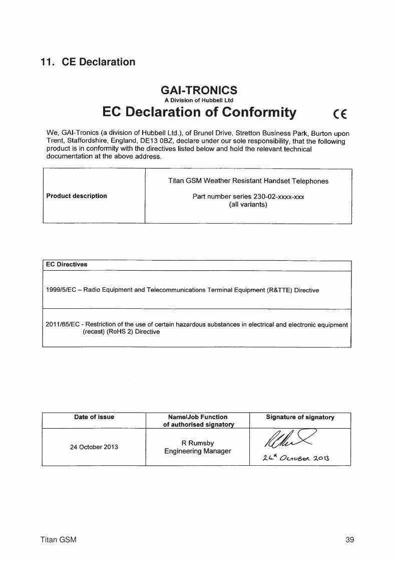
11. CE Declaration

40 Titan GSM
GAI-TRONICS A division of Hubbell Ltd.
Brunel Drive Stretton Park
Burton on Trent DE13 0BZ England
Tel: 01283 500500 Fax: 01283 500400
www.gai-tronics.co.uk
The policy of GAI-Tronics is one of continuous improvement, therefore the Company reserves the right to change specifications without notice
Related Documents