INSTALLATION AND TECHNICAL GUIDE ©2010 AZEK Building Products

Welcome message from author
This document is posted to help you gain knowledge. Please leave a comment to let me know what you think about it! Share it to your friends and learn new things together.
Transcript
INSTALLATION ANDTECHNICAL GUIDE
©2010 AZEK Building Products

Why AZEK®...AZEK Building Products is fueled by forward thinking.
We continually refine product lines and redefine entire product categories.
©2010 AZEK Building Products www.AZEK.com 1
2 www.AZEK.com©2010 AZEK Building Products
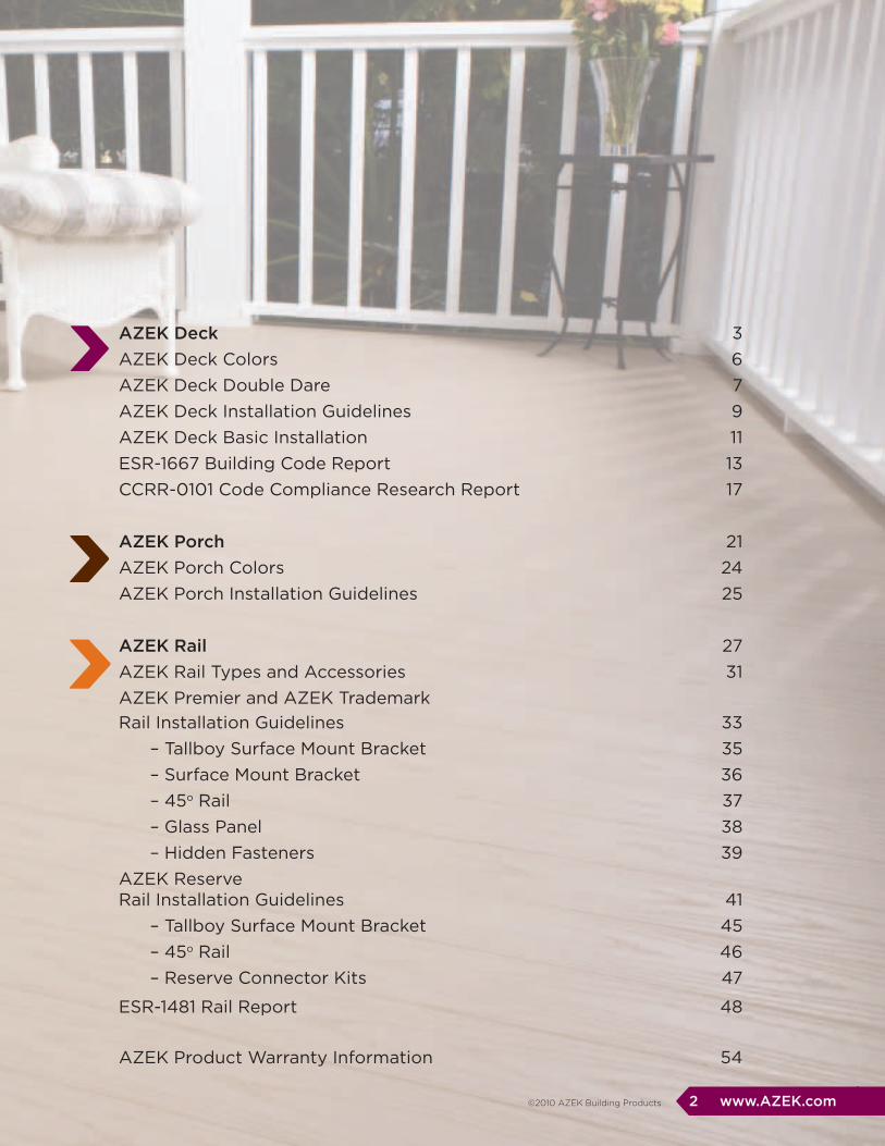
AZEK Deck 3AZEK Deck Colors 6AZEK Deck Double Dare 7AZEK Deck Installation Guidelines 9AZEK Deck Basic Installation 11ESR-1667 Building Code Report 13CCRR-0101 Code Compliance Research Report 17
AZEK Porch 21AZEK Porch Colors 24AZEK Porch Installation Guidelines 25
AZEK Rail 27AZEK Rail Types and Accessories 31AZEK Premier and AZEK Trademark Rail Installation Guidelines 33 – Tallboy Surface Mount Bracket 35 – Surface Mount Bracket 36 – 45o Rail 37 – Glass Panel 38 – Hidden Fasteners 39AZEK ReserveRail Installation Guidelines 41 – Tallboy Surface Mount Bracket 45 – 45o Rail 46 – Reserve Connector Kits 47
ESR-1481 Rail Report 48
AZEK Product Warranty Information 54

Looks Great Now and
For Years to Come.
We’re no strangers to better
performance. AZEK has over
20 years experience in cellular
pvc manufacturing.
Market demand is moving from
wood and composite to the new
category of stain resistant decking.
AZEK Deck is pioneering
this new generation.
©2010 AZEK Building Products www.AZEK.com 3
4 www.AZEK.com ©2010 AZEK Building Products

Resistant to moisture and insects
©2010 AZEK Building Products www.AZEK.com 5
ResistantStain
LimitedLifetime Warranty
Long LastingDurability
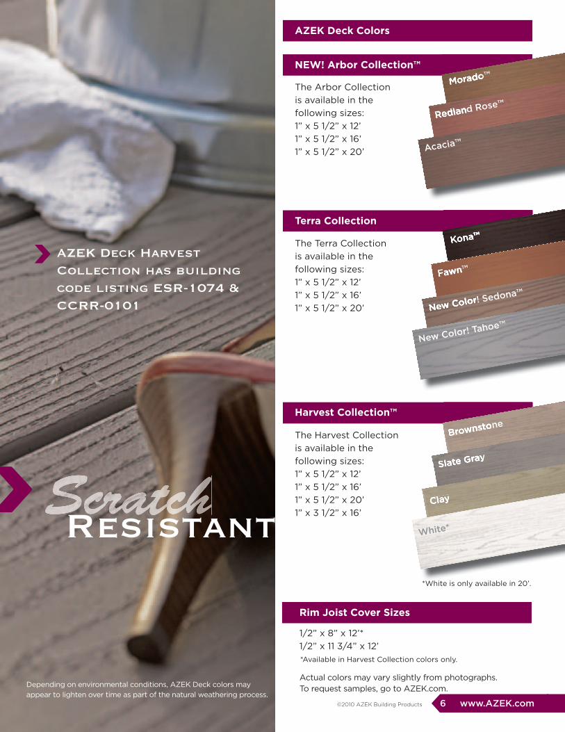
AZEK Deck Harvest Collection has building code listing ESR-1074 & CCRR-0101
6 www.AZEK.com ©2010 AZEK Building Products
rim Joist Cover Sizes
1/2” x 8” x 12’* 1/2” x 11 3/4” x 12’
NEW! Arbor Collection™
AZEK Deck Colors
Terra Collection
harvest Collection™
The Arbor Collection is available in the following sizes:1” x 5 1/2” x 12’ 1” x 5 1/2” x 16’ 1” x 5 1/2” x 20’
The Terra Collection is available in the following sizes:1” x 5 1/2” x 12’ 1” x 5 1/2” x 16’ 1” x 5 1/2” x 20’
The Harvest Collection is available in the following sizes:1” x 5 1/2” x 12’ 1” x 5 1/2” x 16’ 1” x 5 1/2” x 20’1” x 3 1/2” x 16’
Morado™
Kona™
Brownstone
Morado™
Redland Rose™Redland Rose™
Acacia™
Kona™
Fawn™Fawn™
New Color! Sedona™
New Color! Sedona™
New Color! Tahoe™
Brownstone
Slate GraySlate Gray
ClayClay
White*
*White is only available in 20’.
*Available in Harvest Collection colors only.
ScratchResistant
Actual colors may vary slightly from photographs. To request samples, go to AZEK.com.Depending on environmental conditions, AZEK Deck colors may
appear to lighten over time as part of the natural weathering process.
©2010 AZEK Building Products www.AZEK.com 7
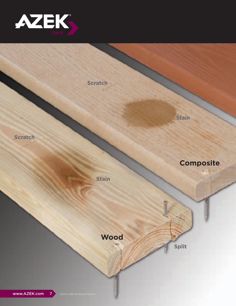
Wood
Composite
Scratch
Stain
Split
Stain
Scratch

8 www.AZEK.com ©2010 AZEK Building Products
AZEK Deck resists scratching from patio furniture, people and pets even in high traffi c areas.
Scratch resistant
AZEK Deck resists staining from stubborn stainmakers like ketchup, cooking grease and red wine.
Stain resistant
AZEK Deck resists splitting from fasteners placed close to the edge.
Split resistant
AZEK
Split
AZEK Deck beats other decking options - wood or composite!
Take the AZEK DeckDouble Dare
STORAGE
TOOLS REQUIRED
PREPARATION
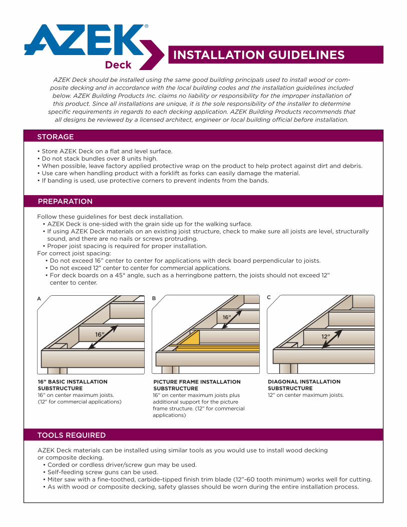
• Store AZEK Deck on a flat and level surface.• Do not stack bundles over 8 units high.• When possible, leave factory applied protective wrap on the product to help protect against dirt and debris.• Use care when handling product with a forklift as forks can easily damage the material.• If banding is used, use protective corners to prevent indents from the bands.
AZEK Deck materials can be installed using similar tools as you would use to install wood decking or composite decking. • Corded or cordless driver/screw gun may be used. • Self-feeding screw guns can be used. • Miter saw with a fine-toothed, carbide-tipped finish trim blade (12”-60 tooth minimum) works well for cutting. • As with wood or composite decking, safety glasses should be worn during the entire installation process.
Follow these guidelines for best deck installation. • AZEK Deck is one-sided with the grain side up for the walking surface. • If using AZEK Deck materials on an existing joist structure, check to make sure all joists are level, structurally
sound, and there are no nails or screws protruding. • Proper joist spacing is required for proper installation. For correct joist spacing: • Do not exceed 16” center to center for applications with deck board perpendicular to joists. • Do not exceed 12” center to center for commercial applications. • For deck boards on a 45° angle, such as a herringbone pattern, the joists should not exceed 12”
center to center.
INSTALLATION GUIDELINES
AZEK Deck should be installed using the same good building principals used to install wood or com-posite decking and in accordance with the local building codes and the installation guidelines included below. AZEK Building Products Inc. claims no liability or responsibility for the improper installation of this product. Since all installations are unique, it is the sole responsibility of the installer to determine
specific requirements in regards to each decking application. AZEK Building Products recommends that all designs be reviewed by a licensed architect, engineer or local building official before installation.
16"
A
16"
B
12"
C
pICTUrE frAmE INSTALLATION SUbSTrUCTUrE16" on center maximum joists plus additional support for the picture frame structure. (12" for commercial applications)
DIAGONAL INSTALLATION SUbSTrUCTUrE 12" on center maximum joists.
16" bASIC INSTALLATIONSUbSTrUCTUrE16" on center maximum joists. (12" for commercial applications)
FASTENERS
CARE AND MAINTENANCE
STAIR CODE COMPLIANCE
EXPANSION AND CONTRACTION
AZEK Deck materials can be installed using similar fasteners as you would use to install wood or composite decking. • Due to the durability of AZEK Deck products, a
high-quality fastener is recommended that meets the following specifications:
• Stainless Steel • Minimum Screw Size: #7 • Minimum Length: 2 1/4” • For salt water coastal applications, we suggest
using the above minimum fastener requirements in 316 stainless steel.
• Color-matched stainless steel deck screws are also available. Your AZEK Building Products dealer can assist with more information on these products.
• Hidden Fasteners: • The Tiger Claw®* TC-P and Fastenmaster’s
Cortex®* are two hidden fastener systems commonly used by contractors installing AZEK Deck. Before using other types of hidden fasteners, check with the manufacturer of the fastener and/or AZEK customer service to ensure compatibility.
To keep your AZEK Deck looking its best: • It is recommended that you wash your deck
periodically with ordinary household products to remove stains, dirt and debris.
• To remove rust stains, use a household cleaner such as a toilet bowl cleaner.
• Avoid the use of rubber-backed mats, tarps, pool toys, and other non-porous items on the deck for any extended period of time as these items may cause discoloration to the decking surface.
• Some products, such as sunblock and insect repellent, contain chemicals that may alter the surface of AZEK Deck. Check product labels and consult with the manufacturer as to product compatibility with plastic materials, such as AZEK Deck, prior to use on or near AZEK Deck.
For ice removal: • Most products containing calcium chloride can
be used without damage to the deck surface. • These products may leave a white residue which
can be cleaned using the cleaning guidelines above.
(These guidelines may not cover every care and maintenance scenario encountered. For additional questions about care and maintenance, call (877) ASK-AZEK.)
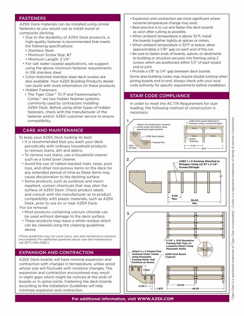
In order to meet the AC 174 Requirement for stair loading, the following method of construction is necessary:
• Expansion and contraction are most significant where extreme temperature change may exist.
• Best practice is to cut and fasten the deck boards as soon after cutting as possible.
• When ambient temperature is above 32°F, install the boards together tightly at splices or miters.
• When ambient temperature is 32°F or below, allow approximately a 1/16” gap on each end of the run.
• Be sure to fasten ends of boards, splices, or abutments to building or structure securely into framing using 2 screws which are positioned within 1/2” of each board end or joint.
• Provide a 1/8” to 1/4” gap between deck boards.Some area building codes may require double joisting when joining boards end to end. Always check with your local code authority for specific requirements before installation.
AZEK Deck boards will have minimal expansion and contraction with changes in temperature, unlike wood whose size will fluctuate with moisture changes. The expansion and contraction encountered may result in slight gaps which might be noticed at the ends of boards or in splice joints. Fastening the deck boards according to the Installation Guidelines will help minimize expansion and contraction.
7.500
3.
1.
2.
* T
iger
Cla
w is
a r
egis
tere
d t
rad
emar
k o
f T
iger
Cla
w In
corp
ora
ted
. * C
ort
ex is
a r
egis
tere
d t
rad
emar
k o
f H
and
y &
Har
man
Co
rpo
rati
on
.
for additional information, visit WWW.AZEK.COm
©2010 AZEK Building Products www.AZEK.com 11
1
4
2
5
3
6
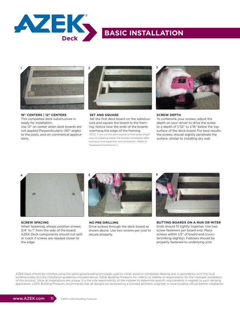
SET AND SqUArESet the first deck board on the substruc-ture and square the board to the fram-ing. Notice how the ends of the boards overhang the edge of the framing.NOTE: If you cut the deck boards to their exact length
prior to installing, fasten the boards immediately after
cutting to limit expansion and contraction. (Refer to
“Expansion/Contraction”.)
NO prE-DrILLINGDrive screws through the deck board as shown above. Use two screws per joist to secure properly.
SCrEW DEpTh To contersink your screws, adjust the depth on your driver to drive the screw to a depth of 1/32” to 1/16” below the top surface of the deck board. For best results, the screws should slightly penetrate the surface, similar to installing dry wall.
bUTTING bOArDS ON A rUN Or mITEr Ends should fit tightly together. Use two screw fasteners per board end. Place screws within 1/2” of board end (coun-tersinking slightly). Fastners should be properly fastened to underlying joist.
16" CENTErS | 12” CENTErSThis completed deck substructure is ready for installation.Use 12” on center when deck boards are not applied Perpendicularly (90° angle) to the joists, and on commerical applica-tions.
SCrEW SpACINGWhen fastening, always position screws 3/4” to 1” from the side of the board. AZEK Deck components should not split or crack if screws are needed closer to the edge.
AZEK Deck should be installed using the same good building principals used to install wood or composite decking and in accordance with the local building codes and the installation guidelines included above. AZEK Building Products Inc. claims no liability or responsibility for the improper installation of this product. Since all installations are unique, it is the sole responsibility of the installer to determine specific requirements in regards to each decking application. AZEK Building Products recommends that all designs be reviewed by a licensed architect, engineer or local building official before installation.
bASIC INSTALLATION
bASIC INSTALLATION
12 www.AZEK.com©2010 AZEK Building Products
7
10
8
11
9
12
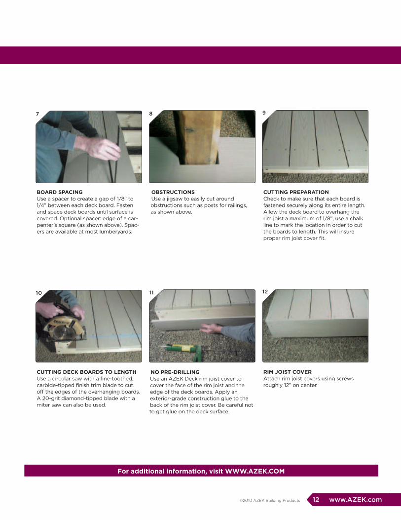
ObSTrUCTIONSUse a jigsaw to easily cut around obstructions such as posts for railings, as shown above.
NO prE-DrILLINGUse an AZEK Deck rim joist cover to cover the face of the rim joist and the edge of the deck boards. Apply an exterior-grade construction glue to the back of the rim joist cover. Be careful not to get glue on the deck surface.
CUTTING prEpArATION Check to make sure that each board is fastened securely along its entire length. Allow the deck board to overhang the rim joist a maximum of 1/8”, use a chalk line to mark the location in order to cut the boards to length. This will insure proper rim joist cover fit.
rIm JOIST COvEr Attach rim joist covers using screws roughly 12” on center.
bOArD SpACINGUse a spacer to create a gap of 1/8” to 1/4” between each deck board. Fasten and space deck boards until surface is covered. Optional spacer: edge of a car-penter’s square (as shown above). Spac-ers are available at most lumberyards.
CUTTING DECK bOArDS TO LENGThUse a circular saw with a fine-toothed, carbide-tipped finish trim blade to cut off the edges of the overhanging boards. A 20-grit diamond-tipped blade with a miter saw can also be used.
for additional information, visit WWW.AZEK.COm
©2010 AZEK Building Products www.AZEK.com 13
©2010 AZEK Building Products www.AZEK.com 15
16 www.AZEK.com ©2010 AZEK Building Products
©2010 AZEK Building Products www.AZEK.com 17
18 www.AZEK.com ©2010 AZEK Building Products
©2010 AZEK Building Products www.AZEK.com 19
20 www.AZEK.com ©2010 AZEK Building Products

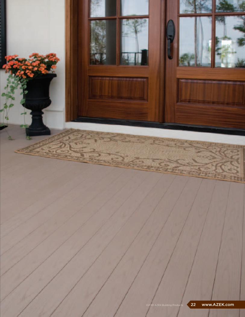
better than wood or
composites, AZEK porch
resists stains and scratches.
Great looking and built to
handle the high traffic that any
porch encounters, AZEK porch
can be used in covered or
uncovered applications.
With AZEK porch, you’ll make
a lasting good impression and
leave many of the hassles of
wood maintenance behind.
©2010 AZEK Building Products www.AZEK.com 21
22 www.AZEK.com ©2010 AZEK Building Products
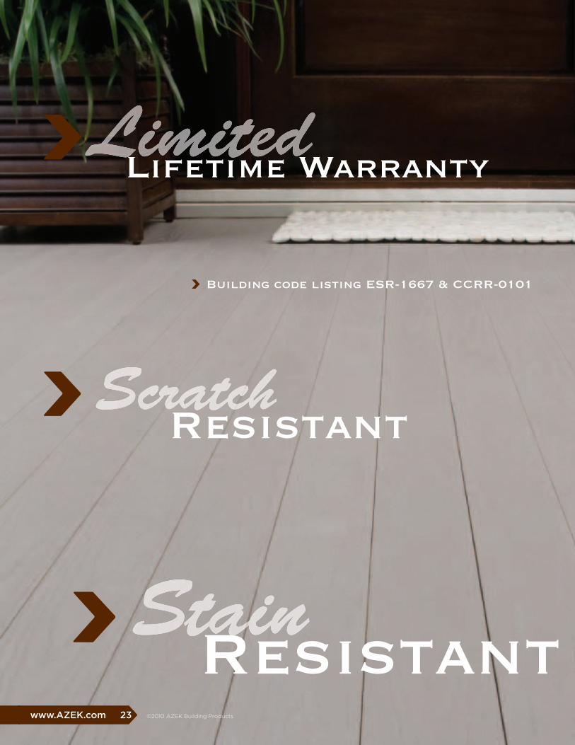
Building code listing ESR-1667 & CCRR-0101
©2010 AZEK Building Products www.AZEK.com 23
ScratchResistant
StainResistant
LimitedLifetime Warranty

Resistant to moisture and insects
24 www.AZEK.com ©2010 AZEK Building Products
AZEK porch Colors
Porch Boards are available in the following sizes:1” x 3 1/8” x 10’ 1” x 3 1/8” x 12’1” x 3 1/8” x 16’
Brownstone
Slate Gray
Perfect for covered or uncovered applications
Actual colors may vary slightly from photographs. To request samples, go to AZEK.com.
Depending on environmental conditions, AZEK Porch colors may appear to lighten over time as part of the natural weathering process.

INSTALLATION DETAILS
Diagram 1
• AZEK Porch is one-sided with the grain side up for the walking surface.
• Install starting board with grooved edge against the house or on the outside edge of the porch if the boards will run perpendicular to the house.
• Attach the starting board by first installing fasteners down through the board at the edge nearest the groove.
• Then attach at each joist by driving a fastener through the tongue at the approximate angle shown in the Diagram 1.
PREPARATION
TOOLS
FASTENERS
Joists should be sloped at 1/4” per foot away from the house to facilitate drainage.
• If using AZEK Porch board on an existing porch, remove existing flooring and make sure joists are structurally sound, free of nails and spaced at a maximum of 16” center to center.
• For new construction, space joists at 16” on center maximum and slope the joists away from the house at 1/4” per foot.
• If installing porch plank at 45˚ angle, space joists at 12” centers.
• Be sure to install sufficient wood blocking below areas where railing posts will be installed.
• Provide proper structural support below AZEK Porch where load bearing columns are present.
• Items related to stair construction, structural framing or any other general construction questions should be reviewed with the local code authority, engineer, or architect.
• AZEK Porch can be installed using the same tools you would use to install wood porch products.
• Corded or cordless driver/screw gun may be used.
• Self-feeding screw guns can be used. Check withmanufacturer for compatibility with AZEK Porch.
• Miter saw with a fine-toothed, carbide-tipped finish trim blade works well for cutting.
• As with installing a wood porch, safety glasses should be worn during the entire installation process.
• Listed are several suggested fastening methods. Addi-tional fastening methods may exist for AZEK Porch.
• Minimum #7 x 2” 305 stainless steel trim head screw with #17 drill point.
• When using a pneumatic flooring nailer, we suggest using barbed/serrated 2” stainless steel cleat “T” nails or “L” cleats.
• For salt water coastal applications, we suggest using the above minimum fastener requirements in 316 stainless steel fasteners.
• Please contact fastener manufacturer to ensure avail-ability, compatibility, and proper use with AZEK Porch.
• When fastened properly, AZEK Porch will demonstrate minimal changes due to expansion and contraction. The expansion and contraction encountered may result in slight gaps which might be noticed at the ends of boards or in splice joints. Best practice is to cut and fasten AZEK Porch boards as soon after cutting as possible.
• When ambient temperature is above 32˚F, install the boards together tightly at splices or miters.
• When ambient temperature is 32˚F or below, allow approximately a 1/16” gap on each end of the run.
• Be sure to fasten ends of boards, splices, or abutments to building or structure securely into framing using a screw which is positioned within 1/2” of each board end or joint.
INSTALLATION GUIDELINES
EXPANSION AND CONTRACTION
AZEK Porch should be installed using the same good building principles used to install wood porch products. Additionally, local building codes and the installation guidelines should be followed. AZEK Building Products claims no
liability or responsibility for the improper installation of our porch product. Since all installations are unique, it is the sole responsibility of the installer to determine specific requirements in regards to each porch application. Best practice is to
have all porch designs reviewed by a licensed architect, engineer or local building official before installation.
©2010 AZEK Building Products www.AZEK.com 25
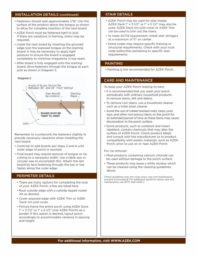
INSTALLATION DETAILS (continued)
CARE AND MAINTENANCE
Remember to countersink the fasteners slightly to provide necessary clearance when installing the next board.
• Continue to add boards per steps 3 and 4 until outer edge of porch is reached.
• Final board may require removal of tongue or rip cutting to a necessary width. Use a table saw or circular saw to accomplish this. Attach the last board by face fastening through the top or toe fasten along the outer edge.
Diagram 2
for additional information, visit WWW.AZEK.COm
PERIMETER DETAILS
STAIR DETAILS
PAINTING
• There are many options for completing the look of your AZEK Porch; a few are listed here.
• Rout outside edge with a carbide tipped router bit as desired.
• Cover exposed edge with AZEK Trim or AZEK Deck rim joist cover.
• Picture frame the entire porch using AZEK Deck 1” x 3 1/2” or 1” x 5 1/2” (not AZEK Porch) as a border. If this option is desired, layout porch accordingly to accommodate variance in spacing and height.
• AZEK Porch may be used for stair treads. AZEK Deck 1” x 3 1/2” or 1” x 5 1/2” may also be used. AZEK Deck rim joist cover or AZEK Trim can be used to trim out the risers.
• To meet AC174 requirement, install stair stringers at a maximum of 11” on center.
• Some codes may require specific framing or structural requirements. Check with your local code authorities pertaining to specific stair requirements.
• Painting is not recommended for AZEK Porch.
• Fasteners should seat approximately 1/16” into the surface of the product above the tongue as shown to allow for complete insertion of the next board.
• AZEK Porch must be fastened tight to joist. If there are variations in framing, shims may be required.
• Install the next board by inserting the grooved edge over the exposed tongue on the starting board. It may be necessary to apply light pressure to ensure the board is engaged completely to minimize irregularity in top seam.
• After board is fully engaged onto the starting board, drive fasteners through the tongue at each joist as shown in Diagram 2.
To keep your AZEK Porch looking its best:
• It is recommended that you wash your porch periodically with ordinary household products to remove stains, dirt and debris.
• To remove rust stains, use a household cleaner such as a toilet bowl cleaner.
• Avoid the use of rubber-backed mats, tarps, pool toys, and other non-porous items on the porch for an extended period of time as these items may cause
discoloration to the porch surface.
• Some products, such as sunblock and insect repellent, contain chemicals that may alter the surface of AZEK Porch. Check product labels and consult with the manufacturer as to product compatibility with plastic materials, such as AZEK Porch, prior to use on or near AZEK Porch.
For ice removal:
• Most products containing calcium chloride can be used without damage to the porch surface.
• These products may leave a white residue which can be cleaned using the cleaning guidelines above.
(These guidelines may not cover every care and maintenance scenario encountered. For additional questions about care and maintenance, call (877) ASK-AZEK.)

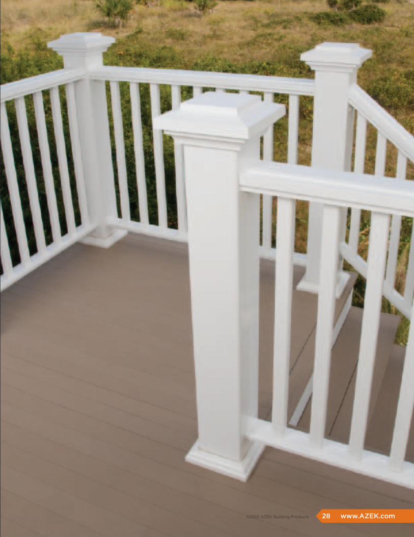
Strong good looks are
just the beginning.
AZEK rail offers the look
and feel of real wood coupled
with the high durability and
low maintenance you expect
from all AZEK products.
www.AZEK.com 27 ©2010 AZEK Building Products
premier rail
Trademark rail
reserve rail
A Style for Every Lifestyle
28 www.AZEK.com ©2010 AZEK Building Products
©2010 AZEK Building Products www.AZEK.com 29

30 www.AZEK.com ©2010 AZEK Building Products
Classic
Luxury
HighDurability

AZEK Trademark railing (available in white)
6’ x 36” x 3 1/2” Rail Kit 6’ x 42” x 3 1/2” Rail Kit 8’ x 36” x 3 1/2” Rail Kit 8’ x 42” x 3 1/2” Rail Kit 6’ x 36” x 2 1/2” Stair Kit w/ Hinge Bracket 6’ x 42” x 2 1/2” Stair Kit w/ Hinge Bracket 6’ Glass Panel Rail Kit 8’ x 3 1/2” Handrail/Retainer Replacement 6’ x 3 1/2” Handrail/Retainer Replacement 6’ x 2 1/2” Handrail/Retainer Replacement 8’ Bottom Rail Replacement 6’ Bottom Rail Replacement35” Baluster Replacement37” Baluster Replacement
AZEK premier railing (available in all colors shown)
AZEK premier railing Sizes
White Slate Gray brownstone
NEW COLOr! Kona NEW COLOr! black
Clay
AZEK Trademark railing Sizes
6’ x 36” x 3 1/2” Rail Kit 6’ x 42” x 3 1/2” Rail Kit 8’ x 36” x 3 1/2” Rail Kit 8’ x 42” x 3 1/2” Rail Kit 6’ x 36” x 2 1/2” Stair Kit w/ Hinge Bracket 6’ x 42” x 2 1/2” Stair Kit w/ Hinge Bracket 6’ Glass Panel Rail Kit 8’ x 3 1/2” Handrail/Retainer Replacement 6’ x 3 1/2” Handrail/Retainer Replacement 6’ x 2 1/2” Handrail/Retainer Replacement 8’ Bottom Rail Replacement 6’ Bottom Rail Replacement35” Baluster Replacement37” Baluster Replacement
www.AZEK.com 31 ©2010 AZEK Building Products
Depending on environmental conditions, AZEK Rail colors may appear to lighten over time as part of the natural weathering process.
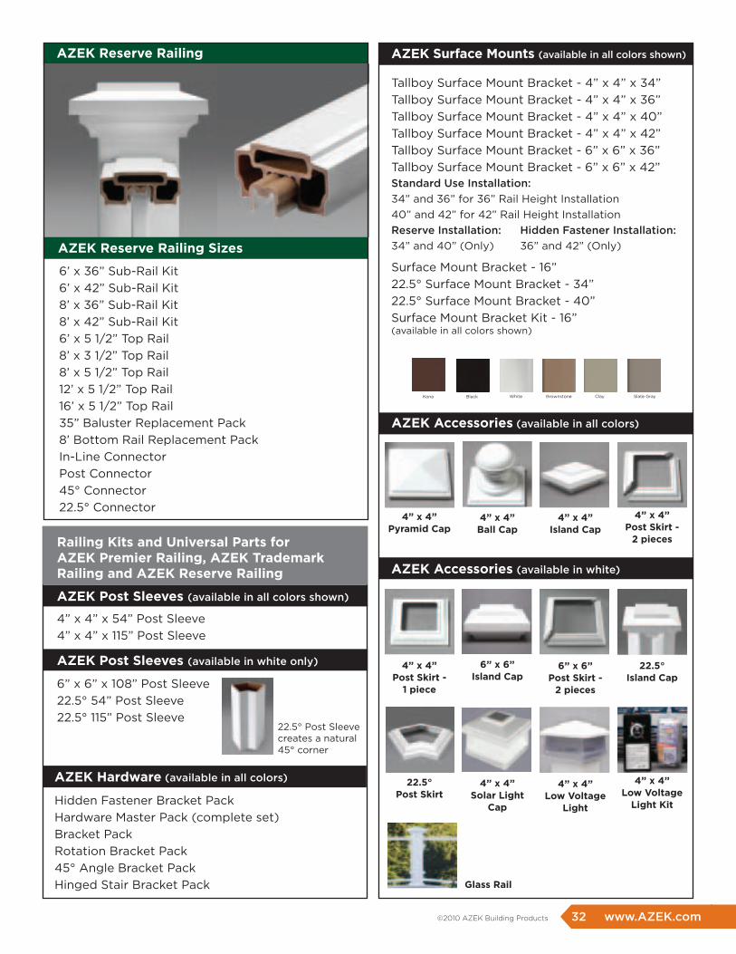
AZEK reserve railing
AZEK post Sleeves (available in all colors shown)
AZEK post Sleeves (available in white only)
railing Kits and Universal parts forAZEK premier railing, AZEK Trademark railing and AZEK reserve railing
AZEK hardware (available in all colors)
AZEK Surface mounts (available in all colors shown)
AZEK Accessories (available in all colors)
Hidden Fastener Bracket Pack Hardware Master Pack (complete set) Bracket PackRotation Bracket Pack45° Angle Bracket PackHinged Stair Bracket Pack
Tallboy Surface Mount Bracket - 4” x 4” x 34”Tallboy Surface Mount Bracket - 4” x 4” x 36”Tallboy Surface Mount Bracket - 4” x 4” x 40”Tallboy Surface Mount Bracket - 4” x 4” x 42”Tallboy Surface Mount Bracket - 6” x 6” x 36” Tallboy Surface Mount Bracket - 6” x 6” x 42”Standard Use Installation: 34” and 36” for 36” Rail Height Installation40” and 42” for 42” Rail Height InstallationReserve Installation: Hidden Fastener Installation:34” and 40” (Only) 36” and 42” (Only)
Surface Mount Bracket - 16” 22.5° Surface Mount Bracket - 34” 22.5° Surface Mount Bracket - 40”Surface Mount Bracket Kit - 16”(available in all colors shown)
WhiteBlackKona Brownstone Clay Slate Gray
AZEK Accessories (available in white)
4” x 4” x 54” Post Sleeve 4” x 4” x 115” Post Sleeve
6” x 6” x 108” Post Sleeve22.5° 54” Post Sleeve22.5° 115” Post Sleeve
AZEK reserve railing Sizes
6’ x 36” Sub-Rail Kit6’ x 42” Sub-Rail Kit8’ x 36” Sub-Rail Kit8’ x 42” Sub-Rail Kit6’ x 5 1/2” Top Rail8’ x 3 1/2” Top Rail8’ x 5 1/2” Top Rail12’ x 5 1/2” Top Rail16’ x 5 1/2” Top Rail35” Baluster Replacement Pack8’ Bottom Rail Replacement PackIn-Line ConnectorPost Connector45° Connector22.5° Connector
4” x 4” pyramid Cap
4” x 4” post Skirt -
1 piece
22.5° post Skirt
Glass rail
4” x 4” ball Cap
6” x 6” Island Cap
4” x 4” Solar Light
Cap
4” x 4” Island Cap
6” x 6” post Skirt -
2 pieces
4” x 4” Low voltage
Light
4” x 4” post Skirt -
2 pieces
22.5° Island Cap
4” x 4” Low voltage
Light Kit
32 www.AZEK.com ©2010 AZEK Building Products
22.5° Post Sleeve creates a natural 45° corner
For AZEK Premier AZEK Trademark
rAILING INSTALLATION GUIDELINES
1. POST SLEEVE INSTALLATIONS
2. POST SLEEVE HEIGHT CALCULATIONS
3. POST SLEEVE MEASUREMENTS & CUTTING
4. RETAINERS & BOTTOM RAIL BRACKET INSTALLATION
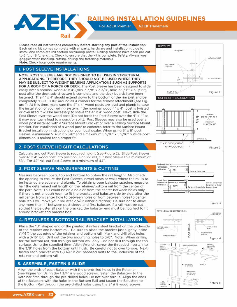
NOTE: POST SLEEVES ARE NOT DESIGNED TO BE USED IN STRUCTURAL APPLICATIONS. THEREFORE, THEY SHOULD NOT BE USED WHERE THEY MAY BE SUBjECT TO WEIGHT BEARING APPLICATIONS SUCH AS SUPPORTS FOR A ROOF OF A PORCH OR DECK. The Post Sleeve has been designed to slide easily over a nominal wood 4” x 4” (min. 3 3/8” x 3 3/8”, max. 3 9/16” x 3 9/16”) post after the deck sub-structure is complete and the deck boards have been fastened. The 4” x 4” should extend down to the bottom of the rim joist and be completely “BOXED IN” around all 4 corners for the firmest attachment (see Fig-ure 1). At this time, make sure the 4” x 4” wood posts are level and plumb to ease the installation of your railing system. If the nominal wood 4” x 4” post is twisted or oversized it will be necessary to shave the 4” x 4” wood post. Next, slide the Post Sleeve over the wood post (Do not force the Post Sleeve over the 4” x 4” as it may eventually lead to a crack or split). Post Sleeves may also be used over a wood post installed with a Surface Mount Bracket or over a Tallboy Surface Mount Bracket. For installation of a wood post to concrete, refer to the Surface Mount Bracket installation instructions or your local dealer. When using 6” x 6” post sleeves, a minimum 5 3/8” x 5 3/8” and a maximum 5 9/16” x 5 9/16” outside post dimension is reuired for a proper fit.
Calculate and cut Post Sleeve to required height (see Figure 2). Slide Post Sleeve over 4” x 4” wood post into position. For 36” rail, cut Post Sleeve to a minimum of 38”. For 42” rail, cut Post Sleeve to a minimum of 44”.
Place the “U” shaped end of the painted stainless steel bracket on the underside of the retainer and bottom rail. Be sure to place the bracket just slightly inside (1/16”) the cut edge of the retainer and bottom rail. Mark and drill pilot holes with a 3/16” bit. Drill out the two mounting holes to 3/8”. Note: When drilling for the bottom rail, drill through bottom wall only – do not drill through the top surface. Using the supplied 6mm Allen Wrench, screw the threaded inserts into the 3/8” holes from the bottom until flush. Be careful not to over torque. Next, fasten each bracket with (2) 1/4” x 20” panhead bolts to the underside of the retainer and bottom rail.
Measure between posts, top and bottom to obtain the rail length. Also check the opening to ensure the Post Sleeves, newel posts or walls where the rail is to be installed are square and plumb. To obtain proper baluster spacing, measure half the determined rail length on the retainer/bottom rail from the center of the part. Note: This could be on a hole or from the center between holes only. If there is not enough room to fit the bracket and baluster side by side, alter the rail center from center hole to between holes or from between holes to center hole (this will move your baluster 2 5/8” either direction). Be sure not to allow any more than 4” between post sleeve and first baluster. If a rail must be cut so that the baluster sits on the bracket, the baluster end must be notched to fit around bracket and bracket bolt.
Please read all instructions completely before starting any part of the installation. Each railing kit comes complete with all parts, hardware and installation guide to install one complete rail section (excluding posts.) Railing sections have been pre-cut to 6 ft. or 8 ft. lengths. Check to ensure that the kit is complete. Safety: Always wear goggles when handling, cutting, drilling and fastening materials. Note: Check local code requirements.
Align the ends of each Baluster with the pre-drilled holes in the Retainer (see Figure 5). Using the 1 3/4” # 8 wood screws, fasten the Balusters to the Retainer first, through the pre-drilled holes. Do not over torque. Align the ends of the Balusters with the holes in the Bottom Rail and fasten the Balusters to the Bottom Rail through the pre-drilled holes using the 3” # 8 wood screws.
5. ASSEmbLE, fASTEN & SLIDE
www.AZEK.com 33 ©2010 AZEK Building Products
Figure 1
36"Or42"
(1) 38 (For 36")Or
(2) 44" (For 42")
4x4 WOOD POST
2" x 8" DECK JOIST
GRADE LEVEL
POST HEIGHT CALCULATION
Figure 2
Figure 3
36"Or42"
(1) 38 (For 36")Or
(2) 44" (For 42")
CENTER SUPPORT
CARRIAGE BOLTS
1" DECKSURFACE
POST SLEEVE
POST CAPACCESSORY
4x4 WOOD POST
2" x 8" DECK JOIST
GRADE LEVEL
POST HEIGHT CALCULATION
3/8"
POST
SLE
EVE
THREADED INSERT
SUPPLIED ALLEN WRENCH
RAIL MOUNTINGBRACKET
1/4" PAN HEAD BOLT
RETAINER ORBOTTOM RAIL
RETAINER AND BOTTOM RAIL
1/2" x 8" or 10" CARRIAGE BOLT
DECK JOISTS
NUT AND WASHER
POST SUPPORTMATERIAL
4" x 4" WOOD POST17/8"
17/8"
TOP VIEW
PRE-DRILLED RETAINER
BALUSTERS4" OPENING
PRE-DRILLED BOTTOM RAIL(5 7/32" O.C.)
5 7/32"3" #8WOODSCREWS(SUPPLIED)
HANDRAIL
HANDRAILSLIDES OVERRETAINER
1 3/4" #8WOODSCREWS(SUPPLIED)
Figure 1
Figure 2
Figure 3
Figure 4
Figure 4
36"Or42"
(1) 38 (For 36")Or
(2) 44" (For 42")
CENTER SUPPORT
CARRIAGE BOLTS
1" DECKSURFACE
POST SLEEVE
POST CAPACCESSORY
4x4 WOOD POST
2" x 8" DECK JOIST
GRADE LEVEL
POST HEIGHT CALCULATION
3/8"
POST
SLE
EVE
THREADED INSERT
SUPPLIED ALLEN WRENCH
RAIL MOUNTINGBRACKET
1/4" PAN HEAD BOLT
RETAINER ORBOTTOM RAIL
RETAINER AND BOTTOM RAIL
1/2" x 8" or 10" CARRIAGE BOLT
DECK JOISTS
NUT AND WASHER
POST SUPPORTMATERIAL
4" x 4" WOOD POST17/8"
17/8"
TOP VIEW
PRE-DRILLED RETAINER
BALUSTERS4" OPENING
PRE-DRILLED BOTTOM RAIL(5 7/32" O.C.)
5 7/32"3" #8WOODSCREWS(SUPPLIED)
HANDRAIL
HANDRAILSLIDES OVERRETAINER
1 3/4" #8WOODSCREWS(SUPPLIED)
Figure 1
Figure 2
Figure 3
Figure 4
Figure 5
36"Or42"
(1) 38 (For 36")Or
(2) 44" (For 42")
CENTER SUPPORT
CARRIAGE BOLTS
1" DECKSURFACE
POST SLEEVE
POST CAPACCESSORY
4x4 WOOD POST
2" x 8" DECK JOIST
GRADE LEVEL
POST HEIGHT CALCULATION
3/8"
POST
SLE
EVE
THREADED INSERT
SUPPLIED ALLEN WRENCH
RAIL MOUNTINGBRACKET
1/4" PAN HEAD BOLT
RETAINER ORBOTTOM RAIL
RETAINER AND BOTTOM RAIL
1/2" x 8" or 10" CARRIAGE BOLT
DECK JOISTS
NUT AND WASHER
POST SUPPORTMATERIAL
4" x 4" WOOD POST17/8"
17/8"
TOP VIEW
PRE-DRILLED RETAINER
BALUSTERS4" OPENING
PRE-DRILLED BOTTOM RAIL(5 7/32" O.C.)
5 7/32"3" #8WOODSCREWS(SUPPLIED)
HANDRAIL
HANDRAILSLIDES OVERRETAINER
1 3/4" #8WOODSCREWS(SUPPLIED)
Figure 1
Figure 2
Figure 3
Figure 4
Figure 1
8
1. Stair Angle
2
3
4
4
Figure 8
Figure 9
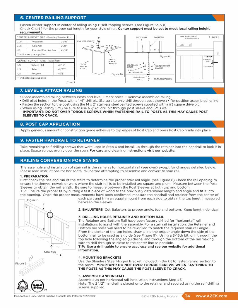
The assembly and installation of stair rail is the same as for horizontal rail (see over) except for changes detailed below. Please read instructions for horizontal rail before attempting to assemble and convert to stair rail.
Manufactured under AZEK Building Products U.S. Patent 6,702,259 B2
• Place assembled railing between Posts and level. • Mark holes. • Remove assembled railing. • Drill pilot holes in the Posts with a 1/4” drill bit. (Be sure to only drill through post sleeve.) • Re-position assembled railing. • Fasten the section to the post using the 14 x 2” stainless steel painted screws supplied with a #3 square drive bit. • When using Tallboy SMB be sure to use a 7/32” drill bit through post sleeve and SMB wall. ImpOrTANT: DO NOT OvEr TOrqUE SCrEWS WhEN fASTENING rAIL TO pOSTS AS ThIS mAY CAUSE pOST SLEEvES TO CrACK.
Apply generous amount of construction grade adhesive to top edges of Post Cap and press Post Cap firmly into place.
Take remaining self drilling screws that were used in Step 6 and install up through the retainer into the handrail to lock it in place. Space screws evenly over the span. For care and cleaning instructions visit our website.
6. CENTEr rAILING SUppOrT
1. prEpArATION First check the rise and run of the stairs to determine the proper stair rail angle. (see Figure 8) Check the rail opening to ensure the sleeves, newels or walls where the stair rail is to be installed are square and plum. Measure between the Post Sleeves to obtain the rail length. Be sure to measure between the Post Sleeves at both top and bottom. TIP: Ensure the proper fit by cutting a test piece of wood to the previously determined length and angle and fit it into the opening. Once the proper measurements have been confirmed, measure the handrail and retainer from the center of each part and trim an equal amount from each side to obtain the top length measured between the sleeves.
2. bALUSTErS Cut Balusters to proper angle, top and bottom. Keep length identical.
3. DrILLING hOLES rETAINEr AND bOTTOm rAIL The Retainer and Bottom Rail have been factory drilled for “horizontal” rail installations to assist with the assembly. For a stair rail installation, the Retainer and Bottom rail holes will need to be re-drilled to match the required stair rail angle. From the center of the top holes, draw a line the proper angle down the side of the bottom rail to be used as a guide (see Figure 9). Using a 3/16th bit, drill through the top hole following the angled guideline, and through the bottom of the rail making sure to drill through as close to the center line as possible. TIp: Use a drill guide to ensure accuracy and see our website for additional information.
4. mOUNTING brACKETS Use the Stainless Steel Hinged Bracket included in the kit to fasten railing section to the posts. ImpOrTANT: DO NOT OvEr TOrqUE SCrEWS WhEN fASTENING TO ThE pOSTS AS ThIS mAY CAUSE ThE pOST SLEEvE TO CrACK.
5. ASSEmbLE AND INSTALL Assemble as per horizontal rail installation instructions Step #5. Note: The 2 1/2” handrail is placed onto the retainer and secured using the self drilling screws supplied.
7. LEvEL & ATTACh rAILING
9. fASTEN hANDrAIL TO rETAINEr
rAILING CONvErSION fOr STAIrS
8. pOST CAp AppLICATION
34 www.AZEK.com ©2010 AZEK Building Products
For AZEK Premier AZEK Trademark
PRE-DRILLEDHOLES
1" SELF-DRILLING SCREWS
BALUSTERS
CENTER SUPPORTBLOCK CENTER OF BOTTOM RAIL
CENTER SUPPORTBRACKET
BOTTOM RAIL
4"
Figure 6b
NOTE: LEVEL RAILING PRIOR TO MARKING & DRILLING
POST
MARK & DRILL HOLES
#14 x 2" SCREWS
CENTERSUPPORTBRACKET
1 3/4" WOOD SCREW
CENTERSUPPORTBLOCK
7/16"1 7/16"
Figure 6a
CENTER SUPPORT SIZE - Premier/Premier Pro
CDN Victorian 215/16”
CDN Colonial 25/8”
US Premier/Premier Pro 45/16”
** indicates size supplied
Chart 1
CENTER SUPPORT SIZE - Trademark
US Select-Flat 45/16”
US Select 45/8”**
US Reserve 43/8”
** indicates size supplied
Figure 7
Fasten center support in center of railing using 1” self-tapping screws. (see Figure 6a & b) Check Chart 1 for the proper cut length for your style of rail. Center support must be cut to meet local railing height requirements.
INSTALL rAIL SECTION4” x 4” AND 6” x 6” AppLICATIONS
POST SLEEVE
SURFACE MOUNT BRACKET
SMB BASE FASTENER
2 pc. POST SKIRT
2" #14ss PAN HEAD SCREW
RAILINGSECTION RAILING MOUNTING BRACKET
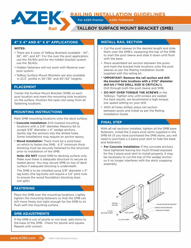
NOTES:
• There are 4 sizes of Tallboy Brackets available - 34”, 36”, 40”, and 42”. For the over the post application, use the 34/40s and for the hidden bracket system use the 36/42s.
• Hidden fasteners will not work with Reserve over post system.
• Tallboy Surface Mount Brackets are also available in 22.5˚ profile in 34”/36” and 40”/42” heights.
Center the Surface Mount Bracket (SMB) at each post location and mark the mounting hole locations on the surface. Position the open slot away from all fastening locations.
Mark SMB mounting locations onto the deck surface.
• Concrete Installation: Drill marked mounting locations with a 3/8” diameter Masonry bit to accept 3/8” diameter x 4” wedge anchors. Gently tap the anchors into the drilled holes. Some installations may require an anchor epoxy.
• Wood Installation: There must be a solid base on which to fasten the SMB. A 5” minimum thick blocking must be securely fastened to the structure prior to installation of the SMB.
Note: DO NOT install SMB to decking surface only. Make sure there is adequate structure to secure as stated above. You may secure SMB on top of deck surface if adequate blocking is underneath.
The SMB is to be installed using 3/8” diameter x 5” lag bolts (the lag bolts will require a 1/4” pilot hole to ensure the wood foundation blocking does not split).
pLACEmENT
mOUNTING INSTrUCTIONS
Place the SMB over the mounting locations. Lightly tighten the mounting fasteners so that the SMB can still move freely, but tight enough for the SMB to sit flush with the mounting surface.
If the SMB is out of plumb or not level, add shims to the base of the SMB. Check for plumb and square. Repeat until correct.
fASTENING
Smb ADJUSTmENTS
• Cut the post sleeves to the desired length and slide them over the SMB’s, squeezing the top of the SMB to start the post sleeve and slide it down until flush with the base.
• Place assembled rail section between the posts and mark the bracket hole locations onto the post sleeves as per the Railing Installation Guide supplied with the railing kit.
• *ImpOrTANT: remove the rail section and drill the bracket hole locations with a 7/32” diameter drill bit (*ThIS DrILL SIZE IS CrITICAL*). Drill through both the post sleeve and SMB.
• DO NOT OvEr TOrqUE ThE SCrEWS in theTallboys. Tighten only until screws are seated. For best results, we recommend a high torque, low speed setting on your drill.
• With all holes drilled, place rail section between posts and install as per the Railing Installation Guide.
With all rail sections installed, tighten all the SMB base fasteners. Install the 2 piece post skirts supplied in the SMB kit (if you have purchased the SMB alone, you will need to purchase a 2 piece post skirt to hide the base and fasteners).
• for Concrete Installation: If the concrete anchors have tightened leaving too much thread exposed for the 2 piece post skirt to install properly, it may be necessary to cut the top of the wedge anchor so it no longer interferes with the skirts snapping assembly.
fINAL STEp
rAILING INSTALLATION GUIDELINES
TALLbOY SUrfACE mOUNT brACKET (Smb)
For AZEK Premier AZEK Trademark
www.AZEK.com 35 ©2010 AZEK Building Products
rAILING INSTALLATION GUIDELINES
SUrfACE mOUNT brACKET
For AZEK Premier AZEK Trademark
Manufactured under AZEK Building Products U.S. Patent 6,702,259 B2
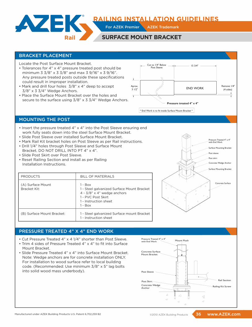
BRACKET PLACEMENT
PRESSURE TREATED 4” X 4” END WORK
MOUNTING THE POST
• Insert the pressure treated 4” x 4” into the Post Sleeve ensuring end work fully seats down into the steel Surface Mount Bracket.• Slide Post Sleeve over installed Surface Mount Bracket.• Mark Rail Kit bracket holes on Post Sleeve as per Rail instructions.• Drill 1/4” holes through Post Sleeve and Surface Mount Bracket. DO NOT DRILL INTO PT 4” x 4”.• Slide Post Skirt over Post Sleeve.• Reset Railing Section and install as per Railing Installation Instructions.
• Cut Pressure Treated 4” x 4 1/4” shorter than Post Sleeve.• Trim 4 sides of Pressure Treated 4” x 4” to fit into Surface Mount Bracket.• Slide Pressure Treated 4” x 4” into Surface Mount Bracket. Note: Wedge anchors are for concrete installation ONLY. For installation to wood surface refer to local building code. (Recommended: Use minimum 3/8” x 5” lag bolts into solid wood mass underbody).
PRODUCTS BILL OF MATERIALS
(A) Surface Mount 1 - BoxBracket Kit: 1 - Steel galvanized Surface Mount Bracket 4 - 3/8” x 4” wedge anchors 1 - PVC Post Skirt 1 - Instruction sheet 1 - Box
(B) Surface Mount Bracket: 1 - Steel galvanized Surface mount Bracket 1 - Instruction sheet
Locate the Post Surface Mount Bracket.• Tolerances for 4” x 4” pressure treated post should be minimum 3 3/8” x 3 3/8” and max 3 9/16” x 3 9/16”. Any pressure treated posts outside these specifications could result in improper installation.• Mark and drill four holes 3/8” x 4” deep to accept 3/8” x 3 3/4” Wedge Anchors.• Place the Surface Mount Bracket over the holes and secure to the surface using 3/8” x 3 3/4” Wedge Anchors.
36 www.AZEK.com ©2010 AZEK Building Products
For AZEK Premier AZEK Trademark
Ø5/8Hole Cut
Path
Length of rail required
Mark #1
Mark #2
Mark #1
Mark #2
For AZEK Premier AZEK Trademark
rAILING INSTALLATION GUIDELINES
45˚rAIL
STEP 1
STEP 2
STEP 4
STEP 5
STEP 6
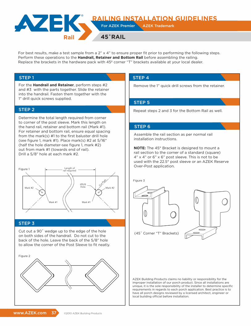
For the handrail and retainer, perform steps #2 and #3 with the parts together. Slide the retainer into the handrail. Fasten them together with the 1” drill quick screws supplied.
Remove the 1” quick drill screws from the retainer.
Repeat steps 2 and 3 for the Bottom Rail as well.
Assemble the rail section as per normal rail installation instructions.
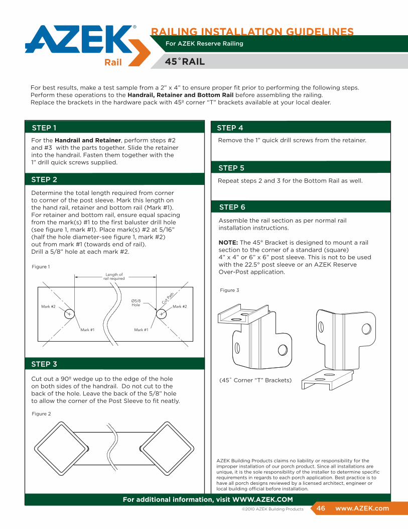
NOTE: The 45° Bracket is designed to mount a rail section to the corner of a standard (square) 4” x 4” or 6” x 6” post sleeve. This is not to be used with the 22.5° post sleeve or an AZEK Reserve Over-Post application.
Determine the total length required from corner to corner of the post sleeve. Mark this length on the hand rail, retainer and bottom rail (Mark #1). For retainer and bottom rail, ensure equal spacing from the mark(s) #1 to the first baluster drill hole (see figure 1, mark #1). Place mark(s) #2 at 5/16” (half the hole diameter-see figure 1, mark #2) out from mark #1 (towards end of rail). Drill a 5/8” hole at each mark #2.
AZEK Building Products claims no liability or responsibility for the improper installation of our porch product. Since all installations are unique, it is the sole responsibility of the installer to determine specific requirements in regards to each porch application. Best practice is to have all porch designs reviewed by a licensed architect, engineer or local building official before installation.
For best results, make a test sample from a 2” x 4” to ensure proper fit prior to performing the following steps. Perform these operations to the handrail, retainer and bottom rail before assembling the railing.Replace the brackets in the hardware pack with 45º corner “T” brackets available at your local dealer.
(45˚ Corner “T” Brackets)
STEP 3
Cut out a 90˚ wedge up to the edge of the hole on both sides of the handrail. Do not cut to the back of the hole. Leave the back of the 5/8” hole to allow the corner of the Post Sleeve to fit neatly.
www.AZEK.com 37 ©2010 AZEK Building Products
Figure 1
Figure 2
Figure 3
STEP 5
STEP 9
GLASS PANEL SIZING
STEP 6
STEP 7
STEP 8
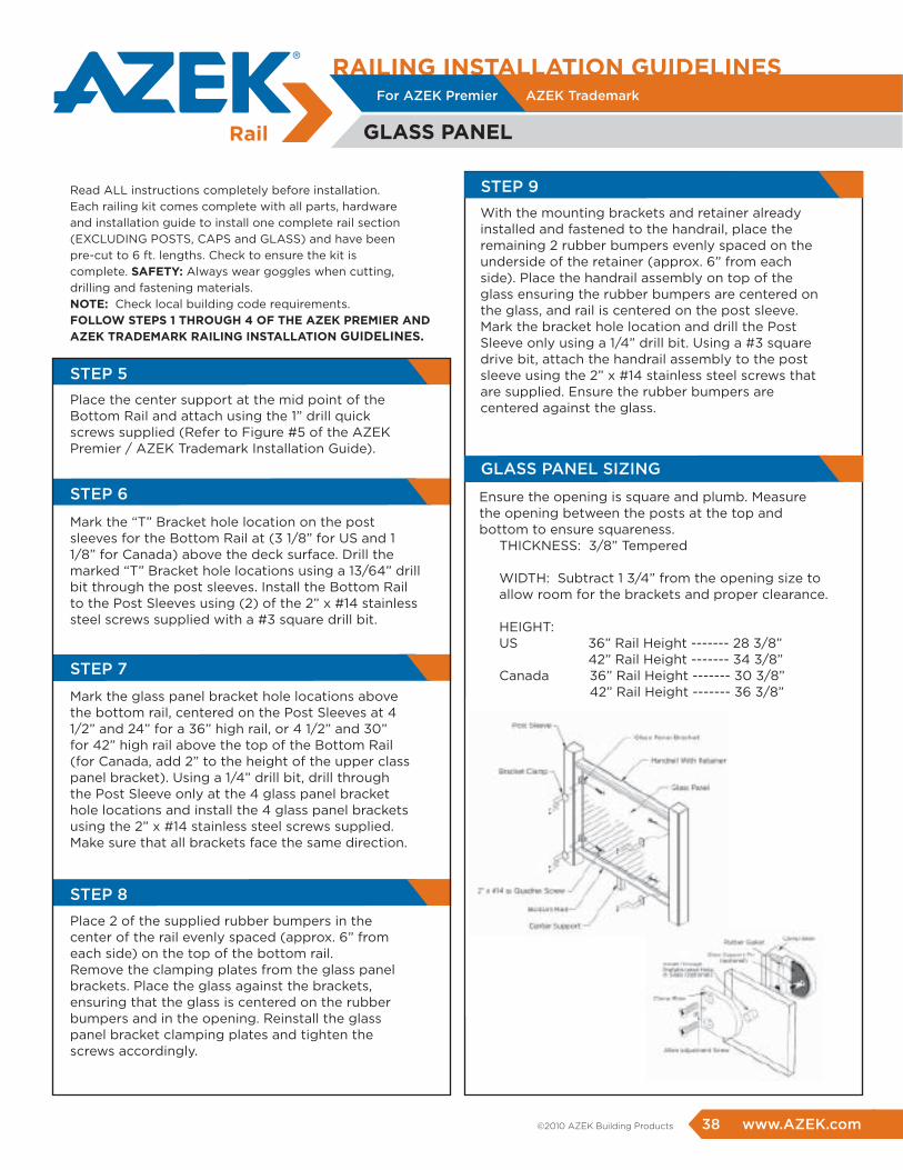
Place the center support at the mid point of the Bottom Rail and attach using the 1” drill quick screws supplied (Refer to Figure #5 of the AZEK Premier / AZEK Trademark Installation Guide).
Mark the “T” Bracket hole location on the post sleeves for the Bottom Rail at (3 1/8” for US and 1 1/8” for Canada) above the deck surface. Drill the marked “T” Bracket hole locations using a 13/64” drill bit through the post sleeves. Install the Bottom Rail to the Post Sleeves using (2) of the 2” x #14 stainless steel screws supplied with a #3 square drill bit.
Mark the glass panel bracket hole locations above the bottom rail, centered on the Post Sleeves at 4 1/2” and 24” for a 36” high rail, or 4 1/2” and 30” for 42” high rail above the top of the Bottom Rail (for Canada, add 2” to the height of the upper class panel bracket). Using a 1/4” drill bit, drill through the Post Sleeve only at the 4 glass panel bracket hole locations and install the 4 glass panel brackets using the 2” x #14 stainless steel screws supplied. Make sure that all brackets face the same direction.
Place 2 of the supplied rubber bumpers in the center of the rail evenly spaced (approx. 6” from each side) on the top of the bottom rail.Remove the clamping plates from the glass panel brackets. Place the glass against the brackets, ensuring that the glass is centered on the rubber bumpers and in the opening. Reinstall the glass panel bracket clamping plates and tighten the screws accordingly.
Read ALL instructions completely before installation. Each railing kit comes complete with all parts, hardware and installation guide to install one complete rail section (EXCLUDING POSTS, CAPS and GLASS) and have been pre-cut to 6 ft. lengths. Check to ensure the kit is complete. SAfETY: Always wear goggles when cutting, drilling and fastening materials.NOTE: Check local building code requirements. fOLLOW STEpS 1 ThrOUGh 4 Of ThE AZEK prEmIEr AND AZEK TrADEmArK rAILING INSTALLATION GUIDELINES.
With the mounting brackets and retainer already installed and fastened to the handrail, place the remaining 2 rubber bumpers evenly spaced on the underside of the retainer (approx. 6” from each side). Place the handrail assembly on top of the glass ensuring the rubber bumpers are centered on the glass, and rail is centered on the post sleeve. Mark the bracket hole location and drill the Post Sleeve only using a 1/4” drill bit. Using a #3 square drive bit, attach the handrail assembly to the post sleeve using the 2” x #14 stainless steel screws that are supplied. Ensure the rubber bumpers are centered against the glass.
Ensure the opening is square and plumb. Measure the opening between the posts at the top and bottom to ensure squareness.
THICKNESS: 3/8” Tempered
WIDTH: Subtract 1 3/4” from the opening size to allow room for the brackets and proper clearance.
HEIGHT: US 36” Rail Height ------- 28 3/8” 42” Rail Height ------- 34 3/8” Canada 36” Rail Height ------- 30 3/8”
42” Rail Height ------- 36 3/8”
rAILING INSTALLATION GUIDELINES
GLASS pANEL
For AZEK Premier AZEK Trademark
www.AZEK.com 33 38 www.AZEK.com ©2010 AZEK Building Products
MEASURING & DRILLING RAILING ASSEMBLY
ROUTING
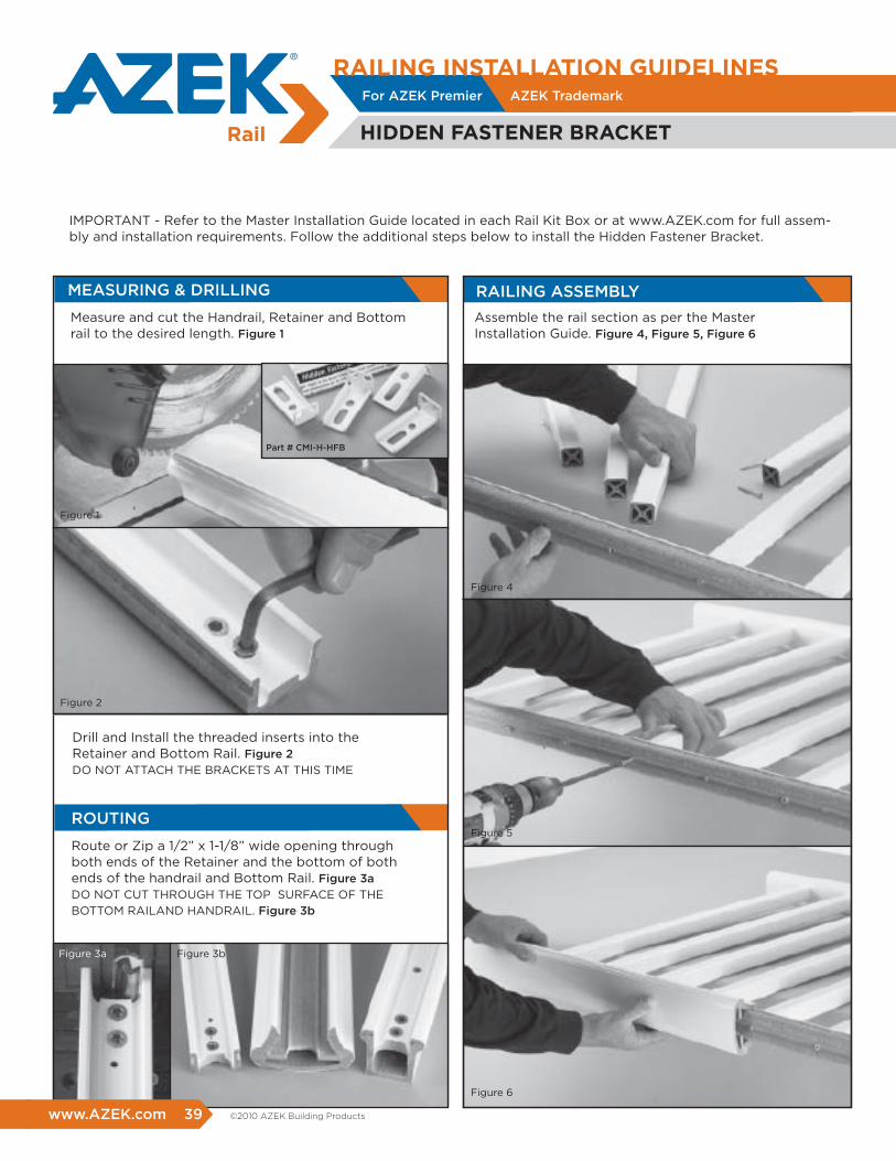
Measure and cut the Handrail, Retainer and Bottom rail to the desired length. Figure 1
Assemble the rail section as per the Master Installation Guide. Figure 4, Figure 5, Figure 6
Route or Zip a 1/2” x 1-1/8” wide opening through both ends of the Retainer and the bottom of bothends of the handrail and Bottom Rail. Figure 3aDO NOT CUT THROUGH THE TOP SURFACE OF THE BOTTOM RAILAND HANDRAIL. Figure 3b
Drill and Install the threaded inserts into the Retainer and Bottom Rail. Figure 2DO NOT ATTACH THE BRACKETS AT THIS TIME
IMPORTANT - Refer to the Master Installation Guide located in each Rail Kit Box or at www.AZEK.com for full assem-bly and installation requirements. Follow the additional steps below to install the Hidden Fastener Bracket.
For AZEK Trademark
hIDDEN fASTENEr brACKET
Part # CMI-H-HFB
For AZEK Premier AZEK Trademark
rAILING INSTALLATION GUIDELINES
www.AZEK.com 39 ©2010 AZEK Building Products
Figure 1
Figure 4
Figure 5
Figure 6
Figure 2
Figure 3a Figure 3b
For AZEK Trademark For AZEK Premier AZEK Trademark
rAILING INSTALLATION GUIDELINESFor AZEK Trademark
BRACKET INSTALLATION RAILING INSTALLATION
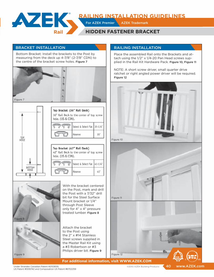
Bottom Bracket: Install the brackets to the Post bymeasuring from the deck up 4-7/8” (2-7/8” CDN) tothe centre of the bracket screw holes. Figure 7
Place the assembled Rail onto the Brackets and at-tach using the 1/2” x 1/4-20 Pan Head screws sup-plied in the Rail Kit Hardware Pack. Figure 10, Figure 11
NOTE: A short screw driver, small quarter drive ratchet or right angled power driver will be required. Figure 12
hIDDEN fASTENEr brACKET
Under Strandex Canadian Patent #2153659, US Patent #5516742 and Composatron US Patent #6702259
for additional information, visit WWW.AZEK.COm
With the bracket centered on the Post, mark and drill the Post with a 7/32” drill bit for the Steel Surface Mount bracket or 1/4” through Post Sleeve only for 4” x 4” pressure treated lumber. Figure 8
Attach the bracket to the Post using the 2” x #14 Stainless Steel screws supplied in the Master Rail Kit using a #3 Robertson or #3 Philips driver bit. Figure 9
40 www.AZEK.com ©2010 AZEK Building Products
For AZEK Premier AZEK Trademark
Figure 7
Figure 8
Figure 9
Figure 10
Figure 11
Figure 12

rAILING INSTALLATION GUIDELINESFor AZEK Reserve Railing
1. POST INSTALLATIONS
Read all instructions completely before starting any part of the installation. Each sub rail kit comes complete with all parts, hardware and installation guide to install one complete sub-rail kit. (EXCLUDING TOP RAIL, POSTS, SKIRTS AND CAPS) sub-rail kits have been pre-cut to 6’ or 8’ lengths. Check to ensure the kit is complete.
SAfETY: Always wear goggles when cutting, drilling, and fastening materials.NOTE: Check local building code requirements prior to installation.
ImpOrTANT NOTES • 5 1/2” Top Rail is sold separately and comes in 6’, 8’, 12’, and 16’ lengths. Use the Top Rail Connectors with all joints including Post, In-Line, 45˚ and 22.5˚ to ensure a proper fit between parts.• For best results, we recommend the use of the Tallboy Surface Mount Brackets for the most secure and strongest method of attachment.• post sleeves are designed to be installed within the height of the rail system they are being used with and are NOT designed for structural use.
The 4” x 4” and 6” x 6” post sleeves have been designed to slide easily over the rust proof coated Tallboy. Follow the Surface Mount Bracket instructions for wood deck or concrete slab before installation of the Post Sleeves. Pressure treated wood 4” x 4” or 6” x 6” can also be used but is not recommended due to uncontrolled swelling, cracking and twisting of the wood. A minimum lumber size of 3 3/8” and a maximum of 3 9/16” is required for proper fit of sleeves. A tight fit is not recommended. When using 6” x 6” post sleeves, a minimum 5 3/8” x 5 3/8” and a maximum 5 9/16” x 5 9/16” outside post dimension is reuired for a proper fit. ImpOrTANT: DETErmINING pOST hEIGhT4” x 4” CENTEr pOSTFor 36” railing height, the post sleeve must be cut to 34”. For 42” railing height, the post sleeve must be cut to 40”.
6” x 6” mAIN pOSTSFor other than column full height 6” x 6” post installations, cut the main 6” x 6” Post Sleeve a minimum of 2” higher than the desired rail height or 38” for a 36” rail or 44” for a 42” rail.
NOTE: If wood posts are being used, small shims may be used if excessive gaps are present in the post sleeves.
www.AZEK.com 41 ©2010 AZEK Building Products
Figure 1
2. RAIL MEASURING AND CUTTING
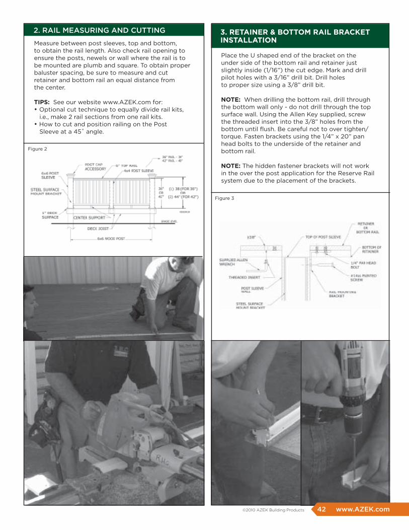
Measure between post sleeves, top and bottom, to obtain the rail length. Also check rail opening to ensure the posts, newels or wall where the rail is to be mounted are plumb and square. To obtain proper baluster spacing, be sure to measure and cut retainer and bottom rail an equal distance from the center.
TIpS: See our website www.AZEK.com for:• Optional cut technique to equally divide rail kits, i.e., make 2 rail sections from one rail kits. • How to cut and position railing on the Post Sleeve at a 45˚ angle.
Place the U shaped end of the bracket on the under side of the bottom rail and retainer just slightly inside (1/16”) the cut edge. Mark and drill pilot holes with a 3/16” drill bit. Drill holes to proper size using a 3/8” drill bit.
NOTE: When drilling the bottom rail, drill through the bottom wall only - do not drill through the top surface wall. Using the Allen Key supplied, screw the threaded insert into the 3/8” holes from the bottom until flush. Be careful not to over tighten/torque. Fasten brackets using the 1/4” x 20” pan head bolts to the underside of the retainer and bottom rail.
NOTE: The hidden fastener brackets will not work in the over the post application for the Reserve Rail system due to the placement of the brackets.
3. rETAINEr & bOTTOm rAIL brACKET INSTALLATION
42 www.AZEK.com ©2010 AZEK Building Products
Figure 2
Figure 3
5. CENTER RAILING SUPPORT
6. CONNECTION TO POSTS
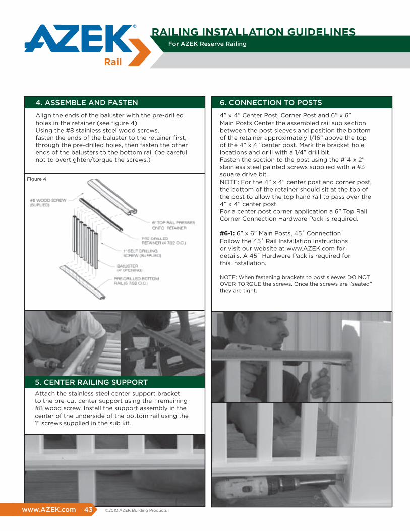
Attach the stainless steel center support bracket to the pre-cut center support using the 1 remaining #8 wood screw. Install the support assembly in the center of the underside of the bottom rail using the 1” screws supplied in the sub kit.
4” x 4” Center Post, Corner Post and 6” x 6” Main Posts Center the assembled rail sub section between the post sleeves and position the bottom of the retainer approximately 1/16” above the top of the 4” x 4” center post. Mark the bracket hole locations and drill with a 1/4” drill bit. Fasten the section to the post using the #14 x 2” stainless steel painted screws supplied with a #3 square drive bit. NOTE: For the 4” x 4” center post and corner post, the bottom of the retainer should sit at the top of the post to allow the top hand rail to pass over the 4” x 4” center post. For a center post corner application a 6” Top Rail Corner Connection Hardware Pack is required.
#6-1: 6” x 6” Main Posts, 45˚ ConnectionFollow the 45˚ Rail Installation Instructions or visit our website at www.AZEK.com for details. A 45˚ Hardware Pack is required for this installation.
NOTE: When fastening brackets to post sleeves DO NOT OVER TORQUE the screws. Once the screws are “seated” they are tight.
4. ASSEMBLE AND FASTEN
Align the ends of the baluster with the pre-drilled holes in the retainer (see figure 4).Using the #8 stainless steel wood screws, fasten the ends of the baluster to the retainer first, through the pre-drilled holes, then fasten the other ends of the balusters to the bottom rail (be careful not to overtighten/torque the screws.)
rAILING INSTALLATION GUIDELINESFor AZEK Reserve Railing
www.AZEK.com 43 ©2010 AZEK Building Products
Figure 4
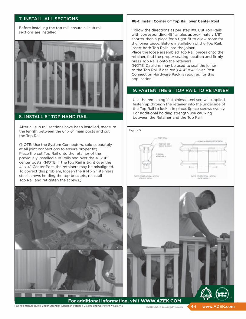
7. INSTALL ALL SECTIONS
8. INSTALL 6” TOP HAND RAIL
9. FASTEN THE 6” TOP RAIL TO RETAINER
Before installing the top rail, ensure all sub rail sections are installed.
After all sub rail sections have been installed, measure the length between the 6” x 6” main posts and cut the Top Rail.
(NOTE: Use the System Connectors, sold separately, at all joint connections to ensure proper fit). Place the cut Top Rail onto the retainer of the previously installed sub Rails and over the 4” x 4” center posts. (NOTE: If the top Rail is tight over the 4” x 4” Center Post, the retainers may be misaligned. To correct this problem, loosen the #14 x 2” stainless steel screws holding the top brackets, reinstall Top Rail and retighten the screws.)
#8-1: Install Corner 6” Top rail over Center post
Follow the directions as per step #8. Cut Top Rails with corresponding 45˚ angles approximately 1/8” shorter than a piece for a tight fit to allow room for the joiner piece. Before installation of the Top Rail, insert both Top Rails into the joiner. Place the loose assembled Top Rail pieces onto the retainer, find the proper seating location and firmly press Top Rails onto the retainers. (NOTE: Caulking may be used to seal the joiner to the Top Rail if desired.) A 4” x 4” Over-Post Connection Hardware Pack is required for this application.
Use the remaining 1” stainless steel screws supplied, fasten up through the retainer into the underside of the Top Rail to lock it in place. Space screws evenly. For additional holding strength use caulking between the Retainer and the Top Rail.
Railings manufactured under Strandex Canadian Patent # 215695 and US Patent # 5516742
for additional information, visit WWW.AZEK.COm44 www.AZEK.com ©2010 AZEK Building Products
Figure 5
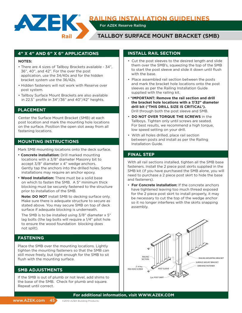
INSTALL rAIL SECTION4” x 4” AND 6” x 6” AppLICATIONS
POST SLEEVE
SURFACE MOUNT BRACKET
SMB BASE FASTENER
2 pc. POST SKIRT
2" #14ss PAN HEAD SCREW
RAILINGSECTION RAILING MOUNTING BRACKET
NOTES:
• There are 4 sizes of Tallboy Brackets available - 34”, 36”, 40”, and 42”. For the over the post application, use the 34/40s and for the hidden bracket system use the 36/42s.
• Hidden fasteners will not work with Reserve over post system.
• Tallboy Surface Mount Brackets are also available in 22.5˚ profile in 34”/36” and 40”/42” heights.
Center the Surface Mount Bracket (SMB) at each post location and mark the mounting hole locations on the surface. Position the open slot away from all fastening locations.
Mark SMB mounting locations onto the deck surface.
• Concrete installation: Drill marked mounting locations with a 3/8” diameter Masonry bit to accept 3/8” diameter x 4” wedge anchors. Gently tap the anchors into the drilled holes. Some installations may require an anchor epoxy.
• Wood Installation: There must be a solid base on which to fasten the SMB. A 5” minimum thick blocking must be securely fastened to the structure prior to installation of the SMB.
Note: DO NOT install SMB to decking surface only. Make sure there is adequate structure to secure as stated above. You may secure SMB on top of deck surface if adequate blocking is underneath.
The SMB is to be installed using 3/8” diameter x 5” lag bolts (the lag bolts will require a 1/4” pilot hole to ensure the wood foundation blocking does not split).
pLACEmENT
mOUNTING INSTrUCTIONS
Place the SMB over the mounting locations. Lightly tighten the mounting fasteners so that the SMB can still move freely, but tight enough for the SMB to sit flush with the mounting surface.
If the SMB is out of plumb or not level, add shims to the base of the SMB. Check for plumb and square. Repeat until correct.
fASTENING
Smb ADJUSTmENTS
• Cut the post sleeves to the desired length and slide them over the SMB’s, squeezing the top of the SMB to start the post sleeve and slide it down until flush with the base.
• Place assembled rail section between the posts and mark the bracket hole locations onto the post sleeves as per the Railing Installation Guide supplied with the railing kit.
• *ImpOrTANT: remove the rail section and drill the bracket hole locations with a 7/32” diameter drill bit (*ThIS DrILL SIZE IS CrITICAL*). Drill through both the post sleeve and SMB.
• DO NOT OvEr TOrqUE ThE SCrEWS in theTallboys. Tighten only until screws are seated. For best results, we recommend a high torque, low speed setting on your drill.
• With all holes drilled, place rail section between posts and install as per the Railing Installation Guide.
With all rail sections installed, tighten all the SMB base fasteners. Install the 2 piece post skirts supplied in the SMB kit (if you have purchased the SMB alone, you will need to purchase a 2 piece post skirt to hide the base and fasteners).
• for Concrete installation: If the concrete anchors have tightened leaving too much thread exposed for the 2 piece post skirt to install properly, it may be necessary to cut the top of the wedge anchor so it no longer interferes with the skirts snapping assembly.
fINAL STEp
for additional information, visit WWW.AZEK.COm
rAILING INSTALLATION GUIDELINES
TALLbOY SUrfACE mOUNT brACKET (Smb)
For AZEK Reserve Railing
www.AZEK.com 45 ©2010 AZEK Building Products
Ø5/8Hole Cut
Path
Length of rail required
Mark #1
Mark #2
Mark #1
Mark #2
For AZEK Reserve Railing
rAILING INSTALLATION GUIDELINES
45˚rAIL
STEP 1
STEP 2
STEP 4
STEP 5
STEP 6
For the handrail and retainer, perform steps #2 and #3 with the parts together. Slide the retainer into the handrail. Fasten them together with the 1” drill quick screws supplied.
Remove the 1” quick drill screws from the retainer.
Repeat steps 2 and 3 for the Bottom Rail as well.
Assemble the rail section as per normal rail installation instructions.
NOTE: The 45° Bracket is designed to mount a rail section to the corner of a standard (square) 4” x 4” or 6” x 6” post sleeve. This is not to be used with the 22.5° post sleeve or an AZEK Reserve Over-Post application.
Determine the total length required from corner to corner of the post sleeve. Mark this length on the hand rail, retainer and bottom rail (Mark #1). For retainer and bottom rail, ensure equal spacing from the mark(s) #1 to the first baluster drill hole (see figure 1, mark #1). Place mark(s) #2 at 5/16” (half the hole diameter-see figure 1, mark #2) out from mark #1 (towards end of rail). Drill a 5/8” hole at each mark #2.
AZEK Building Products claims no liability or responsibility for the improper installation of our porch product. Since all installations are unique, it is the sole responsibility of the installer to determine specific requirements in regards to each porch application. Best practice is to have all porch designs reviewed by a licensed architect, engineer or local building official before installation.
For best results, make a test sample from a 2” x 4” to ensure proper fit prior to performing the following steps. Perform these operations to the handrail, retainer and bottom rail before assembling the railing.Replace the brackets in the hardware pack with 45º corner “T” brackets available at your local dealer.
(45˚ Corner “T” Brackets)
STEP 3
Cut out a 90º wedge up to the edge of the hole on both sides of the handrail. Do not cut to the back of the hole. Leave the back of the 5/8” hole to allow the corner of the Post Sleeve to fit neatly.
for additional information, visit WWW.AZEK.COm46 www.AZEK.com ©2010 AZEK Building Products
Figure 1
Figure 2
Figure 3
For AZEK Reserve Railing
CUTTING THE TOP RAIL
POST CONNECTOR
CONNECTOR INSTALLATION
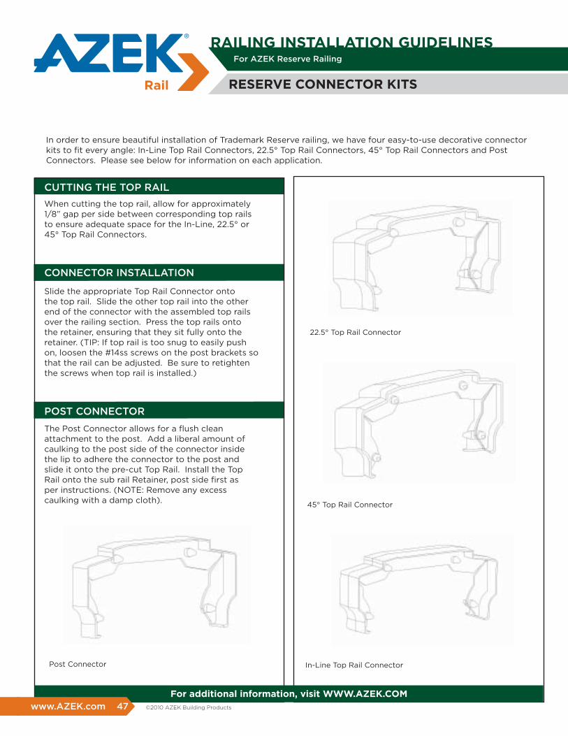
When cutting the top rail, allow for approximately 1/8” gap per side between corresponding top rails to ensure adequate space for the In-Line, 22.5° or 45° Top Rail Connectors.
The Post Connector allows for a fl ush clean attachment to the post. Add a liberal amount of caulking to the post side of the connector inside the lip to adhere the connector to the post and slide it onto the pre-cut Top Rail. Install the Top Rail onto the sub rail Retainer, post side fi rst as per instructions. (NOTE: Remove any excess caulking with a damp cloth).
Slide the appropriate Top Rail Connector onto the top rail. Slide the other top rail into the other end of the connector with the assembled top rails over the railing section. Press the top rails onto the retainer, ensuring that they sit fully onto the retainer. (TIP: If top rail is too snug to easily push on, loosen the #14ss screws on the post brackets so that the rail can be adjusted. Be sure to retighten the screws when top rail is installed.)
In order to ensure beautiful installation of Trademark Reserve railing, we have four easy-to-use decorative connector kits to fi t every angle: In-Line Top Rail Connectors, 22.5° Top Rail Connectors, 45° Top Rail Connectors and Post Connectors. Please see below for information on each application.
22.5° Top Rail Connector
45° Top Rail Connector
Post Connector In-Line Top Rail Connector
rESErvE CONNECTOr KITS
for additional information, visit WWW.AZEK.COm
rAILING INSTALLATION GUIDELINES
www.AZEK.com 47 ©2010 AZEK Building Products
48 www.AZEK.com ©2010 AZEK Building Products
www.AZEK.com 49 ©2010 AZEK Building Products
50 www.AZEK.com ©2010 AZEK Building Products
www.AZEK.com 51 ©2010 AZEK Building Products
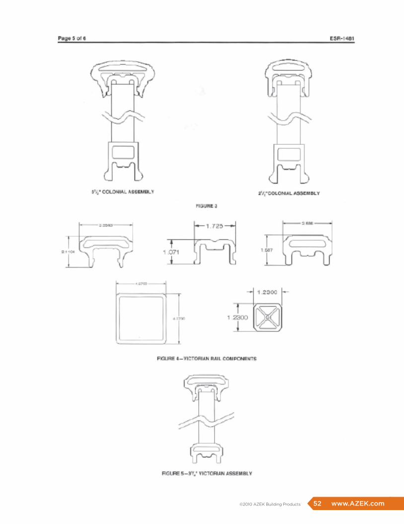
52 www.AZEK.com ©2010 AZEK Building Products
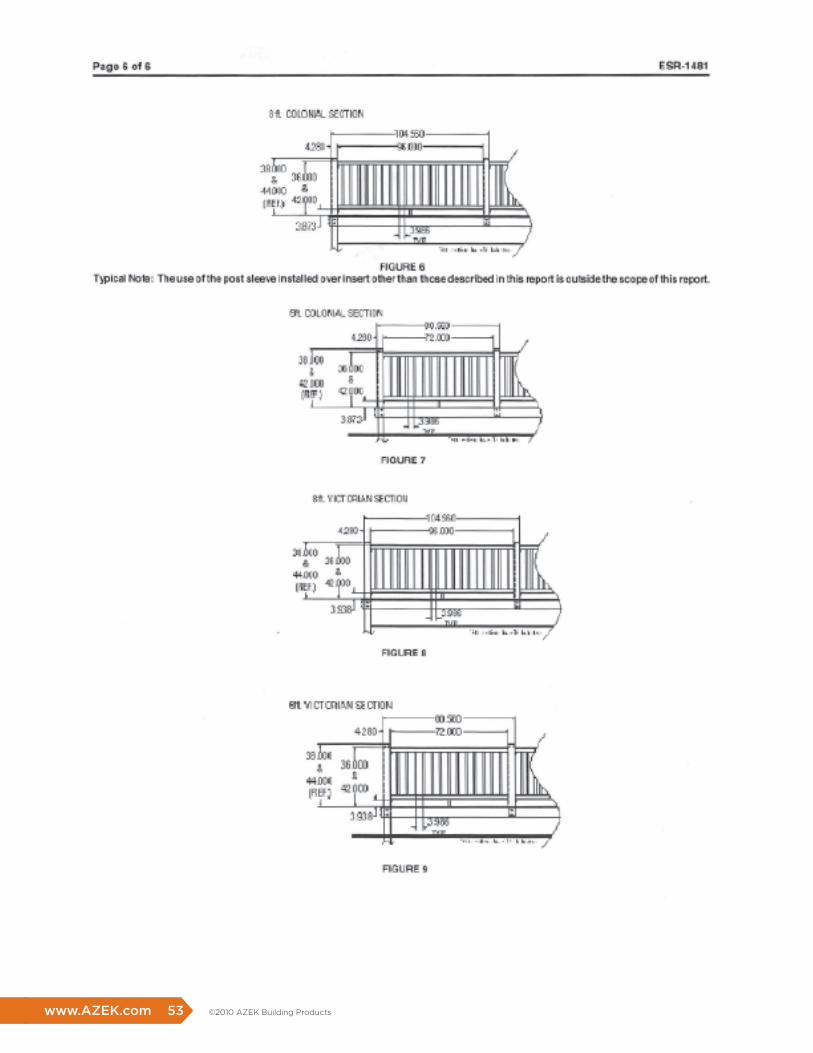
www.AZEK.com 53 ©2010 AZEK Building Products
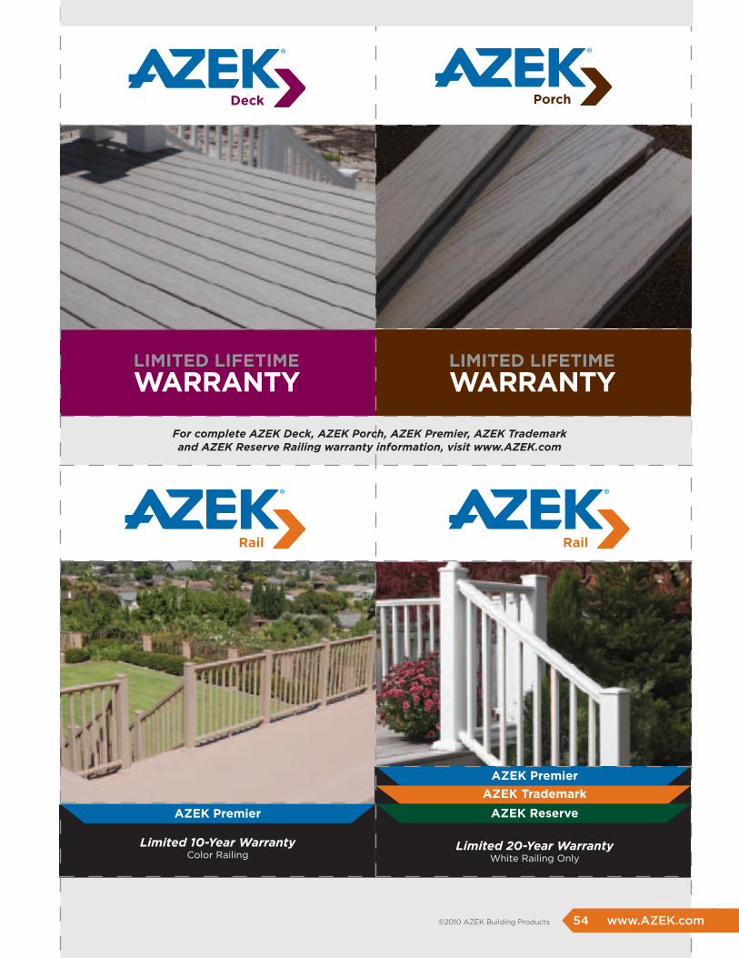
LImITED LIfETImE
WArrANTYLImITED LIfETImE
WArrANTY
AZEK premier
AZEK Trademark
AZEK reserve
Limited 20-Year Warranty White Railing Only
AZEK premier
Limited 10-Year Warranty Color Railing
54 www.AZEK.com ©2010 AZEK Building Products
For complete AZEK Deck, AZEK Porch, AZEK Premier, AZEK Trademark and AZEK Reserve Railing warranty information, visit www.AZEK.com

AZEK Building Products801 Corey Street • Scranton, PA 18505
www.AZEK.com • (877) ASK-AZEK (877) 275-2935
AZLDBTM 12/09
Related Documents