Installation and Maintenance Manual IM672-2 Group: Vision Air Handler Part Number: IM672 Date: April 2003 © 2003 McQuay International Vision Air Handler Sizes 003 - 090

Welcome message from author
This document is posted to help you gain knowledge. Please leave a comment to let me know what you think about it! Share it to your friends and learn new things together.
Transcript

Installation and Maintenance Manual IM672-2
Group: Vision Air Handler
Part Number: IM672
Date: April 2003
© 2003 McQuay International
Vision Air HandlerSizes 003 - 090
IM 672-2 Page 1

Table of ContentsGeneral Information ......................................................3
Receiving and Handling ............................................3Unit Storage ..............................................................3
Installation Guidelines ..................................................4Service Clearances ....................................................4Rigging ......................................................................4Unit Leveling ............................................................5Assembly of Sections ................................................5Ceiling Hung .............................................................7Panels, Frame Channels and Doors ..........................8Face and Bypass Section Mounting ..........................9Multizone Assembly ...............................................11Mounting Actuators ................................................13Piping and Coils ......................................................13Drain Pan Traps ......................................................16Internal Isolation Assembly Adjustment ................16
Electrical Installation .............................................. 17Operation Guidelines ................................................. 18
Startup Checks ........................................................ 18Fan Wheel Alignment ............................................. 19Operating Limits ..................................................... 21Fan Vibration Levels .............................................. 23
Service and Maintenance ........................................... 24Periodic Service and Maintenance .......................... 24Ball Bearing Lubrication ........................................ 24Fan Drive Adjustments ........................................... 24Fan Drive Belt Adjustment ..................................... 28Front Load Filter Option ......................................... 29Filter Gauges ........................................................... 29Coil Maintenance .................................................... 30Component Removal and Replacement .................. 30
Warranty .................................................................... 32
Nomenclature
CAH 003 F D A C
ModelCAH = Custom modular air handlerCAC = Custom modular component
Nominal Unit Size (cataloged sizes - nominal square foot of coil)
003, 004, 006, 008, 010, 012, 014, 017,021, 025, 030, 035, 040, 050, 065, 080, 085, 090
Vintage of McQuay Air Handling Unit
Unit Cross SectionC = Standard unit cross sectionM = Custom size cross section
Motor LocationA = Motor along side of fan housingD = Motor down stream of belt drive
plenum fanF = Motor on inline fanG = Motor downstream of direct drive
plenum fanT = Motor behind twin fan housing
Unit Type/Coil PositionB = Blow-thru cooling coil locationD = Draw-thru cooling coil locationH = Heating onlyV = Vent onlyM = Multizone
Page 2 IM 672-2

General InformationVisionTM air handlers are not designed to be weather resistant and therefore should not be installed outdoors.
The system design and installation must follow accepted indus-try practice, such as described in the ASHRAE Handbook, the National Electric Code, and other applicable standards. The installation of this equipment must be in accordance with regulations of authorities having jurisdiction and all applica-ble codes.
Installation and maintenance must be performed by qualified personnel familiar with applicable codes and regulations, and experienced with this type of equipment. Sheet metal parts, self-tapping screws, clips, and such items inherently have sharp edges, and it is necessary that the installer exercise caution.
Receiving and Handling1. Carefully check items against the bills of lading to verify
all crates and cartons have been received. Carefully inspect all units for damage when received. Report visible or con-cealed damage immediately to the carrier and a file a claim for damage.
2. Vision air handler units are constructed of heavy-gauge galvanized steel and are thoroughly inspected before leav-
ing the factory. Care must be taken during installation to prevent damage to units.
3. Take special care when handling the blower section. All fans are dynamically balanced before leaving the factory. Rough handling can cause misalignment or a damaged shaft. Carefully inspect fans and shaft before unit installa-tion to verify this has not happened.
4. Handle with special care the zone damper of the multi-zone units. Zone dampers are set and inspected before leaving the factory, but should be checked on arrival to the job to verify the bell arm and connecting rod setscrews have not become loose in shipment.
5. Screws, bolts, etc., for assembly of sections are supplied in a bag attached to each section. All necessary gasketing is applied in the factory. Frame members are fully gasketed, and require no additional gasketing for section to section mounting.
Unit StorageStore unit on a level surface. If air handling units are to be stored for any period of time, it is important to periodically rotate the fan wheel. The fan wheel should be periodically rotated to prevent permanent distortion of drive components. In addition, grease may settle in the lower part of the bearing, which may lead to oxidation on the upper portion of the bearing surface. It is also important to keep the fan bearings lubricated.
Store units indoors in a clean, dry environment on a level sur-face. Moisture, debris, and minerals can cause permanent damage to the cabinet and components. Coverings should not be permitted to trap moisture on the galvanized surface.
CAUTION SHARP EDGES AND COIL SURFACESare a potential injury hazard. Avoid contact with them.
ATTENTIONLes bords tranchants et les surfaces des bobines sont un risque de blessure. Ne les touchez pas.
IM 672-2 Page 3

Installation GuidelinesService ClearancesIn addition to leaving adequate space around the unit for pip-ing coils and drains, access to at least one side of the unit is always required to allow for regular service and maintenance of air handling equipment. See Figure 1 for servicing space requirements. Filter replacement, drain pan inspection and cleaning, fan bearing lubrication and belt adjustment are examples of routine maintenance that must be performed. Sufficient space must also be provided on the side of the unit or above the unit for shaft and coil removal if necessary. Space at least equal to the length of the side coil is required for coil removal. Space at least equal to the fin height is required for top coil removal. Refer to the "Coil data" section in Catalog 550 for information about coil sizes.
For routine maintenance purposes, access is normally obtained through the access doors or by removing panels. Fan and filter sections are always provided with a service door on one side of the unit. If requested, doors can be pro-vided on both sides of the unit. Optional service doors are available for most section types, and will be provided based on customer request.
If component replacement is required, the top panel also can be removed. If necessary, the unit can be disassembled. At least 54" of clearance must be maintained in front of electri-cal power devices (Starters, VFDs, Disconnect Switches and Combination Devices). Electrical power devices that are mounted on the side of the unit are typically up to 12" deep. See Figure 2.
Figure 1. Servicing space requirements
Figure 2. Service clearance for electrical power devices
RiggingVision air handlers can ship as separate sections, completelyassembled, or in modules of assembled sections. The unitmust be rigged as it ships from the factory. Do not rigunits after assembly. When a unit is provided with a factoryinstalled base rail, it can be lifted using the 2" diameter lift-ing holes located in the corners of each shipping section. If aunit does not have a base rail, it must be rigged using strapsor a sling. The strapping should be fastened under the skidthat ships with the section.
To prevent damage to the unit cabinetry, use spreader bars. Spreader bars must be in position to stop cables from rubbing the frame or panels. Before hoisting into position, test lift for sta-bility and balance. Avoid twisting or uneven lifting of the unit.
Figure 3. Units on base rails
� � � � � � � � � � � � � � � � � � � �
� � � � �
� � � � � �� � � � � � � � � � � � � � � � � � � � � � � � �
� � � � � � � �� � � � � � � � � �
� � � � � �� � � � �
� � �
� � �
Page 4 IM 672-2

Figure 4. Units on skids
Fan sections that are both greater than 108" wide and are to be stacked on another section are constructed with internal fan support frames that have integral lifting brackets. After the fan section is placed in position, remove and discard the lifting brackets. Install the small panels provided to com-plete the unit cabinet areas where the lifting brackets were located.
Figure 5. Large fan sections that are stacked on top of a lower section
Unit LevelingThe equipment must be placed on a flat and level surface. Where the surface irregularities allow the equipment to dis-tort, the base of the unit must be shimmed to a straight line. Uneven or distorted sections will cause misfit or binding of the doors and panels and improper draining of drain pans.
Units that are over 108" wide must rest on a flat surface for the entire width of the base rails or must be shimmed at one or more points along the length of the rails to prevent distor-tion or sagging of the support rails. See Figure 6.
Figure 6. Leveling the unit
Assembly of SectionsExternal Section to Section MountingVision air handling units can ship fully assembled or as sepa-rate shipping sections. Units that require field assembly of shipping sections must be rigged into position first. Shipping sections are provided with a connection splice joint attached on the leaving air side of the shipping section. The splice joint is insulated, and provides an air-tight seal between two sections once they are assembled together. If the Splice Joint has been bent during shipping or rigging, verify it is restored to its original position. See Figure 10. Use the following pro-cedure to assemble shipping sections:
Horizontal airflow section mounting1. Rig the unit into position and line shipping sections up in
direction of air flow. Sections must be pulled together to fasten. Use a furniture clamp or straps and a ratchet to help pull the sections together securely. See Figure 7.
2. If the unit has a factory installed base rail, fasten base rails together first using the 3/8"-16 by 5" bolts found in the splice kit provided with the unit. To fasten 2 shipping sec-tions together, 4 bolts are needed (2 on each side of the unit). The bolts are run from one base rail into the other and fastened with a nut. Complete each section bottom and top before attaching additional sections.
3. If no base rail is provided, the unit is fastened in the same manner on the bottom and top frame channels. Once the sections are positioned together, remove the fastener in each of the channel corners (on the mating edges in the
� � � � � � � � � � �� � � � � � � � !
" � � � � � � � # � � � � � � !
$ � � � � � � � # � � � �� � � � � � � � � � � � � % � � � � �� � � � � � � � & �
$ � � � � � � � � � � � � ' � � � � �� � ( � � � � � � � � � �� � � � � � �
IM 672-2 Page 5

channel piece). Place a flat section joining plate (found in the splice kit) over the two coned holes in the channels, so that the plate spans the two sections. Replace the fasteners in their original position, through the joining plate.
Figure 7. Horizontal joining sections
Vertical / inverted airflow section mountingFor vertical or inverted arrangements, the bottom tier of sec-tions must be rigged into place and fastened together before lifting any top mounting sections into place. Once bottom level sections are in place and secured, lift stacked compo-nents and fasten using the following procedure: (NOTE: See Face and Bypass Section Mounting on page 9 for the exception to this procedure.)
1. The vertical/inverted section will have a splice joint extending out the top of the bottom joining section. The section that is to be positioned over the opening must be lowered over the splice joint to seal the connection between the two sections.
2. The two sections will be fastened together at the four bot-tom corners of the mating edge. To fasten the corners located on the end of the unit (where bottom section and top section walls are flush with each other), remove the flat head fasteners in the corners of both sections. Cover the coned holes with a flat joining plate and replace the flat head fasteners in the holes to secure the joining plate to both sections. See Figure 8.
3. When one section is deeper than the other, secure the two sections using an L-shaped joining plate. To secure the L shaped bracket, remove the flat head fastener from the corner, position the bracket over the hole, and replace the flathead fastener with a 5/16"-18 x 1" bolt. Once the bolt is in place, secure the bracket to the adjoining section with a 1/4 x 1" drill screw. Repeat the same procedure on both corners of the unit. See Figure 8.
Figure 8. Vertical / inverted joining sections
Extended coil section mountingThe extended coil section is 6" wider than all other sections of the same unit size. The extension is always located on the coil connection side of the unit. Because the extended coil section is wider than other sections, it always ships as a sepa-rate shipping section, and must be joined to other sections in the field. To join an extended coil section to other compo-nents, first follow steps 1-3 for horizontal airflow fastening to secure the opposite connection side. To fasten the connec-tion side, use the following procedure:
1. If the unit has a factory installed base rail, the extended coil section base rail will also be 6" wider than the adjoining base rail. Extended coil section base rails on the connection side are fastened together using the 3/8"-16 by 3" bolts found in splice kit provided with the unit. See Figure 9.
2. If no base rail is provided, the section is fastened in the same manner on the bottom and top. Once the sections are positioned together, remove the fastener in the corner of the channel piece of the section mating to the extended coil section. See Figure 9. Place an L-shaped section joining plate (found in the splice kit) over the coned hole in the channel. Replace the flat head fastener originally used in the corner with a 5/16"-18 1" bolt and fasten it through the L-shaped joining plate. The L-shaped joining plate should now be positioned so that it is butted up against the extended coil section frame channel. To secure the plate to the extended coil section, run two 1/4" x 1" drill screws through the joining plate and into the frame channel.
) � #
* � � � � � � % � � � � � � � � � � �� # � � � � � � � � � %
� � � � + � & � � � � � � � � � �
� � � � � � � � � � � � � � � � %
�
�� �
Page 6 IM 672-2
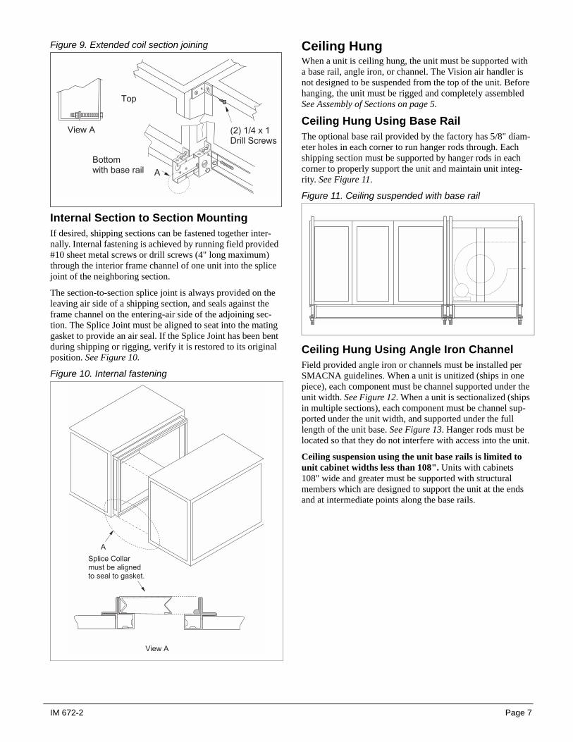
Figure 9. Extended coil section joining
Internal Section to Section MountingIf desired, shipping sections can be fastened together inter-nally. Internal fastening is achieved by running field provided #10 sheet metal screws or drill screws (4" long maximum) through the interior frame channel of one unit into the splice joint of the neighboring section.
The section-to-section splice joint is always provided on the leaving air side of a shipping section, and seals against the frame channel on the entering-air side of the adjoining sec-tion. The Splice Joint must be aligned to seat into the mating gasket to provide an air seal. If the Splice Joint has been bent during shipping or rigging, verify it is restored to its original position. See Figure 10.
Figure 10. Internal fastening
Ceiling HungWhen a unit is ceiling hung, the unit must be supported with a base rail, angle iron, or channel. The Vision air handler is not designed to be suspended from the top of the unit. Before hanging, the unit must be rigged and completely assembled See Assembly of Sections on page 5.
Ceiling Hung Using Base RailThe optional base rail provided by the factory has 5/8" diam-eter holes in each corner to run hanger rods through. Each shipping section must be supported by hanger rods in each corner to properly support the unit and maintain unit integ-rity. See Figure 11.
Figure 11. Ceiling suspended with base rail
Ceiling Hung Using Angle Iron ChannelField provided angle iron or channels must be installed per SMACNA guidelines. When a unit is unitized (ships in one piece), each component must be channel supported under the unit width. See Figure 12. When a unit is sectionalized (ships in multiple sections), each component must be channel sup-ported under the unit width, and supported under the full length of the unit base. See Figure 13. Hanger rods must be located so that they do not interfere with access into the unit.
Ceiling suspension using the unit base rails is limited to unit cabinet widths less than 108". Units with cabinets 108" wide and greater must be supported with structural members which are designed to support the unit at the ends and at intermediate points along the base rails.
, � % � -
* � � � � � �% � � � � � � � � � � � -
) � #
� ! � � . � � � � �/ � � � � $ � % �
, � % � -
-
$ # � � � � 0 � � � � � ' � � � � � � � � � � �� � � � � � � � � � � � � � � �
IM 672-2 Page 7

Figure 12.Ceiling suspended w/o base rail (unitized) construction
Figure 13.Ceiling suspended w/o base rail - modular construction
Panels, Frame Channels and DoorsPanel RemovalTo remove a side or top panel, remove the flat head fasteners along the sides of the panel. Lift the panel off after all fasten-ers are removed.
Frame Channel RemovalFrame channels that run the length of the unit along the top can be removed to allow access to both the side and top of the unit. To remove the frame channel, the side panel(s) must first be removed. Once the side panel is off, remove the flat head fasteners in the corner of the frame channels. The frame channel can then be pulled out the side. Any panel screws that are within one inch of the frame must be removed because they will be engaged into the gasketed flange of the frame. See Figure 14.
Figure 14. Removing panel screws
Fan Section DoorsNOTE: Opening fan section doors requires the use of a 1/2" socket wrench. This satisfies ANSI standards and other codes that require the "use of tools" to access compartments con-taining moving parts or electrical wiring. Figure 15.
1. Remove padlock if one is present.CAUTION: DO NOT attempt to rotate the cup. Damage to the unit will occur.
2. Insert 1/2" socket into cup and rotate 1/4 turn clockwise as shown in Figure 15. If the cup and handle are on the left side of the door, rotate 1/4 turn counter-clockwise.
3. Rotate door handle 1/4 turn clockwise, then 1/4 turn counter-clockwise to release any internal pressure or vac-uum and open the door. If the cup and handle are on the left side of the door, rotate door handle 1/4 turn counter-clockwise, then 1/4 turn clockwise.
4. To prevent air leakage, tighten the door panels by adjust-ing the jam nuts.
� � � � � � � (# � � � � � � % � � � � � � � � � � � � � �
� � � � � # � � �� � � � � � � � � �
Page 8 IM 672-2

Figure 15. Opening fan section door
Face and Bypass Section MountingInternal face and bypass, and external face and bypass for sizes 003-035 are mounted together using the instructions for horizontal components and do not require additional instruction
For all size units that bypass directly into a vertical fan sec-tion and for sizes 040-090 with external face and bypass, use the following instructions.
Bypass into a vertical fan sectionVertical coil sections and the top mounted fan section always ship separately and must be mounted together at the job site. The vertical coil section and the bypass duct will each have a joining collar mounted on the leaving air side of the section and duct respectively. The mounting collar will fit into the side (bypass) and bottom (vertical coil section) openings in the fan section. To correctly position the collars in the fan openings, the fan and coil section must be assembled first. Use the following steps for assembly. See Figure 16.
1. Place the vertical coil section in position. If an access sec-tion is positioned downstream from the coil section and not already assembled to the coil section, secure the two sections together.
2. Lift the fan section on top of the vertical coil section, taking care to line up the joining collar in the bottom of the fan section.
3. For sizes 003-035, the bypass duct is integral to the unit construction and does not require attachment to the bypass section. For sizes 040-090, the bypass duct must be posi-tioned and assembled to the bypass section before joining to the fan.
4. Once the fan is positioned on top of the vertical coil section and the bypass duct and bypass section are assembled, posi-tion the two assemblies and line up the joining collars with the openings in the fan and vertical coil section.
5. Once the sections are lined up and in position, secure the unit together by fastening joining plates to the unit.
Figure 16. Assembly of fan coil sections
1 2 3 4, � % � � � � � � � � � � � � � �
5 � � �4 ' � �
5 � � � � � � � 0 � � � �
IM 672-2 Page 9

Unit Sizes 040 - 090 External Face and Bypass Duct AssemblyWhen unit sizes 040-090 are ordered with external face and bypass, the bypass duct ships separately and must be attached to the unit in the field. The joining of the bypass duct to the unit must be done after the unit has been assembled. Also, if the bypass duct is over 90" long the duct will not ship in one piece and must be field assembled. The field assembly of the bypass duct to the unit requires the following steps.See Figure 17.
1. Position the unit shipping sections together and assemble in the equipment room.
2. After the unit is assembled, lift the duct into position over the unit. Joining collars are shipped factory assembled to the unit and duct. There will be a joining collar located in the top of the bypass opening, and in the leaving air side
of the bypass duct. These joining collars are used to pro-vide air seals. Line up the duct with the top openings in the unit.
3. If the bypass duct is longer than 90", the duct will ship in more than one piece and must be field assembled. The piece of duct that has the joining collar on the bottom should be placed on top of the unit first. Once that is in place, position the other piece of duct. Take care to fit the splice collar into the first piece of duct and then lower the other end into the bypass opening.
4. Once the duct is positioned correctly, fasten the duct pieces together with the joining plate provided. Do this by removing the fasteners in the corners of the duct assem-blies, place the plate over the holes in the corners and replace the fasteners. See Figure 7 on page 6.
Figure 17. Assembly of bypass duct to unit
5 � � � � � � � 0 � � � �
5 � � � � � � � 0 � � � �
5 � � � � � � � 0 � � � �
Page 10 IM 672-2

Multizone AssemblyThe multizone section may ship completely assembled or it may ship in numerous pieces. Whether the section ships in a single piece or multiple pieces will depend on customer requirements and the unit size. When a multizone section is over 90" high or 90" wide, it must be split into sections for shipping.
The unit may ship in 1, 2, 3, 4, or 5 separate pieces. Typically the multizone damper assembly will ship separately (see Multizone Damper Assembly on page 12) and must be attached at the job site. The damper should be attached after the other components are assembled. Use the following instructions for assembly of the multizone section. See Figure 18.
1. If the diffuser and the cold deck section ship separately, join them together first. The joining collar mounted in the diffuser fits into the entering air side of the coil section. Line up the two sections and fasten them together.
2. Once the diffuser and cold deck sections are joined, the hot deck and bypass sections can be lifted in place, on top of the diffuser/cold deck section. If possible, assemble the hot deck and bypass section (if there is one) together before lifting on top. There will always be a joining collar in the diffuser. The joining collar provides the seal between the sections joints. It is important to line up and fit the collar in the hot deck and bypass section. For verti-cal applications, the cold deck also has a joining collar in the discharge opening. This collar will fit in the bottom of the vertical bypass section.
3. After the components in the multizone are fitted together, fasten the joining plates to the corners in the unit exterior.
4. If a damper was ordered, assemble it to the section. See Multizone Damper Assembly on page 12.
NOTE: Verify that the joining collars are aligned to seat into the gasket. Straighten any collars that are distorted from shipping or from rigging.
Figure 18. Assembly of multizone sections
JoiningCollars
Diffuser Cooling Coil
Zone Damper Assembly
Upper Unit - Heating (and optional bypass)
IM 672-2 Page 11

Multizone Damper AssemblyWhen a multizone unit is ordered with dampers, depending on the multizone configuration and size, the damper assem-bly may ship separately (all horizontal and units with a total height over 90").
When the dampers are not factory assembled to the unit, they will ship to the job site on a skid. An assembly kit including screws and an instruction drawing are included with the damper for field assembly to the unit.
First remove the side plate that encloses insulation from both sides of the damper assembly. Then lift the damper assembly
into position. See Figure 19. Fasten the assembly to the frame channels within the multizone openings. Use caulking to seal up the areas around the unit frame channel to prevent any air leakage. After caulking, the side plates can be put back in place and secured.
Damper shaft extensions are provided on both ends of the damper assembly for actuation. The dampers are linked together by a linkage bar on both ends of the damper. The linkage bar is cut at the time of installation to divide the damper into the required number of zones. See Multizone Damper Adjustment on page 13.
Figure 19. Damper assembly
Duct ConnectionsFlexible connectors should be used on the outlet and inlet duct connections of all units. Each zone divider has a "W" shaped duct clip. Insert ductwork into this clip. See Figure 20.
Figure 20. Duct connectors
$ � � � % � � � � � � ' � � �� � � � � � � � � � � � �
- � � � � � %� � � � � � � � � � � � � � �
� � � � � � � � � � � (� � � � ' � � � � � � � # � � � �� � � � � � � � � � � # �� � � � � � � % � � � ' � � � � � �
/ � � � � � � % � � � � � �� � � � � � � � � � % � � � � 6 � � � - * � � � � �� � � � � � � % �
� . � � - * � � � � �1 # � � � � � # � � � � � � �� � � � � � � % � � � � � � � � � �
" � � � � � � � � % � � � � � � � � # � � � � �� � # � � � 7 � � � � � � � � � � � � �� � � # � � � � � � � � � � � � � � � � � � � �# � � � � � � � � � � � � � � � � � � �� � � � � � � 8 � � �
/ � � # � � � � � �� � � � � � ' � � � �� � � % � � � � � � � %� � � � � � � # � � � � �� � � � � � � � � �
/ ' � � � % � �/ ' � � � � � � #
9 � � � � � � � �
Page 12 IM 672-2

Multizone Damper AdjustmentThe installer must clear the damper assemblies of construc-tion dirt and debris. These materials will result in higher torque requirements and may bend or damage damper com-ponents.
If multizone dampers do not close properly, adjust the blades as follows:
1. Loosen setscrews in bell arms for all zones.2. Close all cold deck dampers tightly.3. Move bell arms so they are at a 45° angle to the vertical
center when viewing the zone dampers from the cold deck end of the damper section. See Figure 21.a. 2-Deck Zone Dampers -The cold deck will be closed
when the bell arms are 45° from the vertical center. The hot deck will be closed when the bell arms are 45° clockwise from the vertical center.
b. 3-Deck Zone Dampers -The cold deck will be closed when the bell arms are 45° clockwise from the vertical center. The hot deck will be closed when the bell arms are 45° counterclockwise from the vertical center.
4. Tighten setscrews on bell arms while holding the dampers closed.
5. Zone damper blades should all close properly. If one or a few zones do not close completely, the procedure can be repeated for these zones.
Figure 21. Bell arms at 45° angle to vertical center
Mounting ActuatorsThe installing contractor is responsible for the mounting of all field-installed actuators. No provisions are made for the location of these actuators due to the number of options and arrangements available and the variety of specific applica-tions. Typically, actuators are mounted inside the cabinet. Provide proper support for the actuator to avoid excessive stress in the cabinet, linkage, or damper shafts.
Multizone, Mixing Box and Economizer Damper Torque RequirementsOn multizone units, the actuator must drive the connection link for proper damper actuation. Multiple dampers must not be actuated from the shaft extension opposite the connection link.
Fresh air and return air dampers can be linked together and driven from the same actuator if the dampers are the same size. If the dampers are different sizes, they must be driven by separate actuators and controlled appropriately. Exhaust dampers are always driven by a separate actuator.
A typical rotary electric actuator can handle up to 40 sq. ft. of damper. For pneumatic actuators, allow 5 in-lb. per square foot of damper area.
Face Bypass Damper Torque RequirementsFace and bypass dampers may or may not be linked together. When dampers are placed before a single bank of coils, they are always linked together and require a single actuator. When dampers are bypassing a stacked or staggered coil, the dampers are not linked and will require multiple actuators. Unit size 040-090 provided with external face and bypass will require three actuators, other arrangements with stacked or staggered coils will require two actuators. A damper shaft extension is provided. The shaft extension is normally located on the drive side of the unit, but can be moved to the other side.
Face and bypass dampers have a torque requirement of 10 in-lbs. per square foot of damper face area.
Piping and CoilsFollow applicable piping design, sizing, and installation information presented in ASHRAE Handbooks in the design and installation of piping. Observe all local codes and indus-try standards. Undue stress should not be applied at the con-nection to coil headers. Pipework should be supported independently of the coils.
Water Cooling Coils1. Water supply, water return, drain, and vent connections
extend through the end panel of the coil section. All con-nections are labeled on the end panel.
2. Water supply and water return connections are typically male N.P.T. iron pipe.
3. When installing couplings, do not apply undue stress to the connection extending through unit panel. Use a
� � : � � :
0 � � � � � � � � �
* � � � � �
� � � � � � � � � � � � � � �
� � : � � :
* � � � � �
� � � � � � � � � � � � � � � � � � � � � � � � � � � � � � � � � � �
To divide the damper section into multiple zones, cut and remove sufficientconnecting link to allow adjacent zones to operate independently.Note: The damper blades on 2-deck dampers will seal through severaldegrees of shaft rotation. The damper blades can rotate 360° and do notengage a stop. The hot deck blades are mounted at a 90° to the cold deckblades. Linkages and dampers should be set up and adjusted before thezone ducts are installed. If adjustment is required and access to the bladesis restricted, cold deck blade position usually can be observed by removingthe cabinet panel on the coil section.
IM 672-2 Page 13

backup pipe wrench to avoid breaking the weld between coil connection and header.
4. Follow recommendations of the control manufacturer regarding types, sizing, and installation of controls.
Direct Expansion Coils1. The coil distributor and suction connection extend
through the end panel of the coil section.2. Check nozzle in distributor for proper tonnage.3. When a thermostatic expansion valve is supplied with the
unit, it will be located outside the unit and connected directly to the distributor. Do not apply heat to the body of the expansion value.
4. The thermostatic expansion valve must be of the external equalizer tube type. Connect the 1/4-inch diameter exter-nal equalizer tube provided on the coil to connection on expansion value.
5. Use care when piping up the system to see that all joints are tight and all lines are dry and free of foreign material. For typical refrigerant piping, see condensing unit product manual.
Steam Coils (refer to Figure 22 on page 15)1. All steam coils in units are pitched toward return connection.2. Steam supply and steam return connections are typically
male N.P.T. iron pipe and are labeled on the end panel of coil section. Connections extend through coil section end panel.
3. When installing couplings, do not apply undue stress to the connection extending through unit panel. Use a backup pipe wrench to avoid breaking the weld between coil connection and header.
4. Support piping independently of coils and provide ade-quate piping flexibility. Stresses resulting from expansion of closely coupled piping can cause serious damage.
5. Do not reduce pipe size at the coil return connection. Carry return connection size through the dirt pocket, mak-ing the reduction at the branch leading to the trap.
6. Install vacuum breakers on all applications to prevent retaining condensate in the coil. Generally, the vacuum breaker is to be connected between the coil inlet and the return main, the vacuum breaker should be open to the atmosphere, and the trap design should allow venting of large quantities of air.
7. Do not drip supply mains through the coil.8. Do not attempt to lift condensate when using modulating
or on/off control.9. Size traps in accordance with manufacturers' recommen-
dations. Be certain that the required pressure differential will always be available. Do not under-size.
10.Float and thermostatic or bucket traps are recommended for low pressure steam. On high pressure steam, bucket traps are normally recommended. Thermostatic traps should be used only for air venting.
11.Bucket traps are recommended for use with on/off control only.
12.Locate traps at least 12 inches below the coil return connection.
13.Multiple coil installation.a. Each coil or group of coils that is individually con-
trolled must be individually trapped.b. Coils in series: Separate traps are required for each
coil, or bank of coils, in series.c. Coils in parallel: A single trap may generally be used
but an individual trap for each coil is preferred.d. Do not attempt to lift condensate when using modulat-
ing or on/off control.14.With coils arranged for series airflow a separate control is
required on each bank or coil in the direction of airflow.15.Modulating steam valves are not recommended on high
pressure systems.16.Modulating valves must be sized properly. Do not
under size.17.Freezing conditions (entering air temperatures below 35°F).
a. 5JA, 8JA, 5RA and 8RA coils are strongly recommended.
b. 5 psi steam must be supplied to coils at all times.
c. Modulating valves are not recommended. Controlshould be provided by face and bypass dampers.
d. Consideration should be given to the use of two or threecoils in series with two position steam control valves onthat coil or coils which will be handling 35°F or colderair. The desired degree of control can be attained with amodulating valve on the downstream coil.
e. Thoroughly mix fresh air and return air before it entersthe coil. Also, temperature control elements must beproperly located to obtain true air mixture temperatures.
f. As additional protection against freeze-up, the trapshould be installed sufficiently below coil to providean adequate hydrostatic head to provide removal ofcondensate during an interruption in the steam pres-sure. Estimate three feet for each 1 psi of trap differ-ential required.
g. On startup, admit steam to coil ten minutes beforeadmitting outdoor air.
h. Close fresh air dampers if steam supply pressure fallsbelow minimum specified.
Page 14 IM 672-2

Figure 22. Piping arrangements
Vacuum breaker1/2" check valve
Steam main
1/4" petcockfor continuousair venting
High pressurefloat or buckettrap
Return main
1" min.
12" min.
Vacuum breaker1/2" check valve
Steam main
1/4" petcockfor continuousair venting
High pressurebucket trap
Return main
1" min.
12" min.
Full size ofreturn conn.
Vacuum breaker1/2" check valve
Steam main
Return main
12" min.
Vacuum breaker1/2" check valve
Steam main
Return main
Vacuum breaker1/2" check valve
Steam main
Return main
12" min.
Vacuum breaker1/2" check valve
Steam main
Return main
12" min.
Full size ofreturn conn.
Check Valve Strainer Gate ValveControl valvemodulatingtwo position
Float andthermostatic trap
High pressure (over 25 psi)
Low pressure (to 25 psi)
5GA or 8GA coils. Note that theaddition of a vacuum breaker topermit the coil to drain duringshutdown.
5TA, 8TA, or 5HA coils. Conden-sate is lifted to overhead returnmain
5JA or 8JA coil. Installed in series.Note that each coil must have aseparate control valve and trap.
5RA, 8RA, or 5SA coils. Banked twohigh, individual trapping of each coil asshown is preferred.
5RA, 8RA, or 5SA coils. Installed
5J, 5G, 8J or 8G coils.
IM 672-2 Page 15

Water Heating Coils1. Water supply and water return connections extend through
the end panel of the coil section. All connections are labeled on the end panel.
2. Water supply and water return connections are male N.P.T. iron pipe.
3. When installing couplings, do not apply undue stress to the connection extending through unit panel. Use a backup pipe wrench to avoid breaking the weld between coil connection and header.
4. Follow recommendations of the control manufacturer regarding types, sizes, and installation of controls.
5. Hot water coils are not recommended for use with enter-ing air below 40°F.
6. If fresh air and return air are to be heated by a hot water coil, care should be used in the design of the system to provide thorough mixing before air enters the coil.
7. For preparation of coils for winter operation, see page 29.
Drain Pan TrapsDrain lines and traps should be run full size from the drain pan connection. Drain pans should have traps to permit the condensate from the coils to drain freely. On both blow-through and draw-through units, the trap depth and the dis-tance between the trap outlet and the drain pan outlet should be twice the static pressure in the drain pan section under normal operation for the trap to remain sealed. See Figure 23.
Figure 23. Allow adequate distance between trap outletand drain outlet
Note: The door panels on some applications have a close clearance over the drain pipes. Extend the drain fitting with a coupling if necessary for door clearance. See Figure 24.
Figure 24. Extend drain fitting for door clearance
Internal Isolation Assembly AdjustmentOn units with internally isolated fan and motor assemblies, the assemblies have been secured for shipment.
Before operating the unit:Remove the shipping brackets and tie-down bolts (See Figure 26) and discard. The shipping brackets located on the oppo-site drive side of the unit are difficult to access from the drive side of the unit. Either remove them before the unit is assem-bled, or remove the panel on the opposite drive side to gain access.
The spring isolators under the four corners of the fan and motor assembly have been factory adjusted while the fan was not running. See Table 1. With the unit operating at normal cfm and static pressure, the isolators should all be at the same height opening. If adjustments are required, loosen the 1/2" capscrew on top of the isolator and turn the adjusting bolt to lower or raise the fan and motor base. Retighten the capscrew when adjustments are completed.
2 � � ' � 2 !� � � � � � � � � � � # � �
� 2
� 2
0 � � � � �
/ � � �
Page 16 IM 672-2

Table 1: Spring mount adjustments
For models 040 through 090 the isolators should be at equal height during fan operation (6"). The fan outlet should be centered in the outlet panel opening. If adjustment is required, loosen the capscrew on top of the isolator assembly. Turn the adjustment nut below the fan frame to lower or raise the fan motor and frame assembly. Re-tighten the capscrew on top of the isolator assembly. See Figure 25.
Figure 25. Adjusting large spring mount assembly
Figure 26. Removing shipping brackets
Electrical Installation1. Electrical service to the fan must correspond to the rated
voltage on the motor nameplate and be in conformance with the National Electric Code and local restrictions.
2. The fan section metal frame must be connected to the building electrical ground.
3. A door electrical interlock is not provided as standard.4. Thermal motor protection is external to the unit. Unless the
unit is provided with a variable frequency drive (VFD) or a unit mounted starter, thermal protection and a disconnect switch provision per electric codes are provided by others.
5. When the unit is factory provided with a disconnect switch, starter or a variable frequency drive (VFD), the components are mounted on the outside of the unit cabi-net. Factory wiring is provided from the device to the unit internal motor.
SPRING MOUNT ADJUSTMENT AT RESTFan Discharge
PositionTop or Bottom Horz.
HDownblast
H Upblast H
Unit Sizes 003-035
1 3.75 3.75 4.25
2 4.25 3.75 4.25
3 4.25 3.75 4.25
4 3.75 3.75 4.25
Unit Sizes 040-090
1 6.00 6.00 6.50
2 6.50 6.00 6.50
3 6.50 6.00 6.50
4 6.00 6.00 6.50
Adjusting Bolt
6"
; � � �
< � �
2 1 $ � �
2 1 $ � �2 1 $ � �
2 1 $ � �
- � � � � %
< � � � � � � � � � � � # � � � � � � � � � ' � � �
/ � � � � � � �
$ # � � � � � � � � �
� � = ' � � � � � � � � %
$ # � � � � � � � � �
� � = ' � � � � � � � � %
$ � � # # � � � � � � � �� � % � � � � %
$ � � # # � � �
� � � � �
/ � � � � � -
$ � � # # � � � � � � � � � � � % � � � � � � � � � � � � � � � ) ( # � � � � � � � # � � � � !
$ � � � � � � � � - �
$ � � # # � � � � � � � � � � � � � � � � � � � � � � � ) ( # � � � � � � � # � � � � !
Unit sizes 006 - 090
IM 672-2 Page 17

Operation GuidelinesStartup ChecksWhen performing startup and service, thorough safety pre-cautions must always be taken. These functions must be per-formed by trained, experienced personnel.
Before starting up the unit:Make sure that fan electrical power source is disconnected and locked in the "OFF" position before entering fan section.
1. Check that the unit is completely and properly installed with ductwork connected. Check that all construction debris is removed and filters are clean.
2. Check that all electrical work is complete and properly terminated. Check that all electrical connections are tight and that the proper voltage is connected. Phase imbalance must not exceed 2%.
3. Ball bearings on fan shaft and motor are prelubricated and do not need grease before startup.
4. Check tightness of setscrews in bearings and fan wheel(s). If retightening is needed, make certain the fan wheel(s) are positioned per Table 2 or Table 3. Setscrews are torqued per Table 6.CAUTION:Equipment damage due to loose fastenersrepresents improper start-up and equipment abuse. It is not covered by the warranty.
5. Check alignment of fan and motor sheaves and belt ten-sion. Adjust if necessary. Check tightness of sheave set-screws and/or capscrews. See Figure 43 & 44.
6. Leak test thermal system to verify that connections are tight.7. Check that condensate drain is trapped.8. Rotate shaft by hand to be sure it is free.9. Fan startup: Fan should start and run. Observe the rota-
tion. If the fan is operating backward, reverse two legs of the 3-phase supply power.
Note: Variable pitch fan drives are usually provided for oper-ation in the mid-speed adjustment range. However, the drives are usually shipped with the adjustment opened up for mini-mum fan speed. The drives should be adjusted for the proper airflow. See Fan Drive Adjustments on page 24.
After first 48 hours of operation:1. Disconnect and lock electrical power source. Check tight-
ness of all bearing, wheel, and sheave setscrews (or cap-screws). See Table 6.
2. Recheck belt tension and adjust if necessary. Belts ten-sioned sufficiently to slip one to two seconds at startup will perform satisfactorily, extending life and reducing vibration. If retensioning is necessary, be certain sheave alignment is retained.
WARNING ROTATING FAN
Can cause severe injury or death. Before servicing fans, lockout and tag out power.
AVERTISSEMENT PIÈCES MOBILES DANGEREUSES.Avant de réparer ou entretenir les ventilateurs, coupezl'alimentation èlectrique de cet appareil et bloquez lecommutateur à OFF.
WARNING FIRE/ELECTRIC SHOCK HAZARD.Can cause property damage, personal injury or death.Fan power supply must be wired and motor framegrounded in accordance with local electric codes.
AVERTISSEMENTRisques d´incendie et d' électrocution pouvant causerdes dommages matériels, des blessures et même lamort. L'alimentation électrique du moteur du ventilateurde même que la mise à la terre du chàssis du moteurd o i v e n t ê t r e f a i t s c o n fo r m ém e n t a u x c o d e sd'installations électriques en vigueur.
WARNING FAN MOTOR REQUIRES
OVERLOAD PROTECTION.Failure to provide motor overload protection can result in fire, property damage, electric shock, personal injury
or death. Connect motor to an overload protective device rated in compliance with local electric codes.
AVERTISSEMENTRisques d´incendie et d' électrocution pouvant causerdes dommages matériels, des blessures et même lamort. Connecter au moteur du ventilateur électrique undispositif de protection contre les surcharges conformeaux codes d'installations électriques en vigueur.
CAUTION DO NOT OVERHEAT FAN MOTORHigh air temperatures in the fan section can cause the fanmotor to burnout. On draw-through air handlers or airhandlers with the fan section down the air stream from theheating section, the discharge air temperature of theheating section must not exceed 104°F (40°C).
ATTENTIONRisques de dommages dans le moteur du ventilateurélectrique. Si Ia température de l'air a proximité duventilateurest élevée, le moteurdu ventilateur électriquepeut chauffer et brûler. Sur les transmetteurs d'air àcirculation transversale ou les transmetteurs dont leventilateur est en aval de l'unité de chauffage, régler latempérature de l'air sortant de l'unité de chauffage à40°C (104°F).
Page 18 IM 672-2
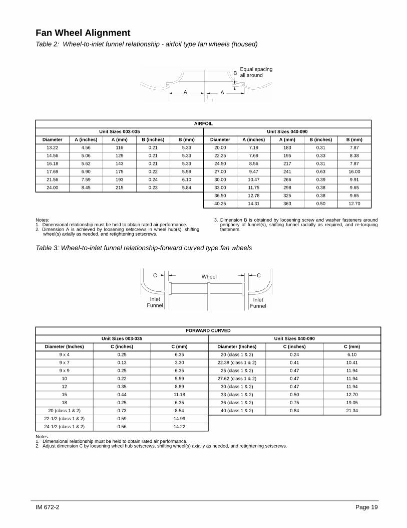
Fan Wheel AlignmentTable 2: Wheel-to-inlet funnel relationship - airfoil type fan wheels (housed)
Notes:1. Dimensional relationship must be held to obtain rated air performance.2. Dimension A is achieved by loosening setscrews in wheel hub(s), shifting
wheel(s) axially as needed, and retightening setscrews.
3. Dimension B is obtained by loosening screw and washer fasteners aroundperiphery of funnel(s), shifting funnel radially as required, and re-torquingfasteners.
Table 3: Wheel-to-inlet funnel relationship-forward curved type fan wheels
Notes:1. Dimensional relationship must be held to obtain rated air performance.2. Adjust dimension C by loosening wheel hub setscrews, shifting wheel(s) axially as needed, and retightening setscrews.
AIRFOILUnit Sizes 003-035 Unit Sizes 040-090
Diameter A (inches) A (mm) B (inches) B (mm) Diameter A (inches) A (mm) B (inches) B (mm)13.22 4.56 116 0.21 5.33 20.00 7.19 183 0.31 7.87
14.56 5.06 129 0.21 5.33 22.25 7.69 195 0.33 8.38
16.18 5.62 143 0.21 5.33 24.50 8.56 217 0.31 7.87
17.69 6.90 175 0.22 5.59 27.00 9.47 241 0.63 16.00
21.56 7.59 193 0.24 6.10 30.00 10.47 266 0.39 9.91
24.00 8.45 215 0.23 5.84 33.00 11.75 298 0.38 9.65
36.50 12.78 325 0.38 9.65
40.25 14.31 363 0.50 12.70
- -
*3 > ' � � � � # � � � � �� � � � � � ' � �
FORWARD CURVEDUnit Sizes 003-035 Unit Sizes 040-090
Diameter (Inches) C (inches) C (mm) Diameter (Inches) C (inches) C (mm)9 x 4 0.25 6.35 20 (class 1 & 2) 0.24 6.10
9 x 7 0.13 3.30 22.38 (class 1 & 2) 0.41 10.41
9 x 9 0.25 6.35 25 (class 1 & 2) 0.47 11.94
10 0.22 5.59 27.62 (class 1 & 2) 0.47 11.94
12 0.35 8.89 30 (class 1 & 2) 0.47 11.94
15 0.44 11.18 33 (class 1 & 2) 0.50 12.70
18 0.25 6.35 36 (class 1 & 2) 0.75 19.05
20 (class 1 & 2) 0.73 8.54 40 (class 1 & 2) 0.84 21.34
22-1/2 (class 1 & 2) 0.59 14.99
24-1/2 (class 1 & 2) 0.56 14.22
" � � �< ' � � �
� � �0 0
" � � �< ' � � �
IM 672-2 Page 19

Table 4: Wheel-to-inlet funnel relationship - plenum fans
Table 5: Wheel-to-inlet funnel relationship - inline fans
Table 6: Bearing collar and wheel hub setscrew torque
WHEEL — FUNNEL OVERLAPSIZE OVERLAP13.5 .120
15 .190
16.5 .250
18.25 .310
20 .380
22.25 .440
24.5 .500
27 .560
30 .620
33 .750
36.5 .810
40.25 .880
44.5 .940
49 1.000
54.25 1.060
60 1.120
OVERLAP
im672-46.dsf
WHEEL — FUNNEL OVERLAPSIZE OVERLAP150 .375
165 .438
182 .562
200 .625
222 .688
245 .750
270 .812
300 .875
330 1.000
365 1.125
402 1.250
445 1.375
OVERLAP
im672-47.dsf
SETSCREW MINIMUM TORQUEDiameter (inches) ft. / lbs. kg. / M.
1/4 5.5 .76
1/16 10.5 1.45
3/8 19.0 2.63
7/16 29.0 4.01
1/2 42.0 5.81
5/8 92.0 12.72
Page 20 IM 672-2

Operating LimitsDo not exceed the operating limits in Table 7. A fan wheel that is operated beyond the rpm and temperature limits
shown may suffer permanent distortion or fracture. The resulting unbalance may cause severe unit vibration.
Table 7: Unit sizes 003-035
Figure 27. Torque for FC variable inlet vanes (in. - lb.) Figure 28. Torque for AF variable inlet vanes (in. - lb.)
Table 8: Unit sizes 040-090
FAN OPERATING LIMITS
Forward curved — Housed
Diameter 9 x 4 9 x 7 9 x 9 10.62 12.62 15 18 20 22.25 24.50
Maximum RPM Class I N/A 2189 2223 1934 1614 1328 1155 1050 944 858
Maximum RPM Class II 2244 2854 2896 2518 2091 1725 1450 1200 1030 910
Airfoil — Housed
Diameter 13.22 14.56 16.19 19.69 21.56 24.00
Maximum RPM Class I 3000 3000 2300 2000 1700 1500
Maximum RPM Class Il 4335 3918 3457 2858 2427 2255
300
250
200
150
1009080
Tor
que
(in. -
lb.)
350
400
450
500
600
650
700
750
800
850
1000
1500
Fan Speed (rpm)
500
400350
300
250
200
550
900
FC20.00
FC36.00
FC33.00
FC30
.25
FC27.6
2FC25
.00
FC22.38
300250200
150
1009080706050
750
800
850
900
1000
1500
2000
Fan Speed (rpm)
403530
AF24.00
AF21.56
AF19.69
AF16.19
AF14.56
AF13.22
2500
3000
3500
4000
4500
350400450
Torq
ue (i
n. -
lb.)
FAN OPERATING LIMITS
Forward curved — Housed
Diameter 20 22.38 25 27.62 30.25 33 36 40.25
Maximum RPM Class I 1010 930 790 690 650 600 560 420
Maximum RPM Class II 1281 1178 1011 910 835 763 715 550
Airfoil — Housed
Diameter 20 22.25 24.5 27 30 33 36.5 40.25
Maximum RPM Class I 2077 1875 1691 1479 1328 1209 1073 972
Maximum RPM Class Il 2703 2413 2199 1928 1730 1579 1401 1264
IM 672-2 Page 21

Figure 29. Torque for FQ variable inlet vanes (in.- lb.) Figure 30. Torque for AF variable inlet vanes (in.- lb.)
Table 9: Operating limits — plenum fans
Figure 31. Torque requirements at 100% WOV for SWSI plenum fans with NESTED inlet vane
300
250
200
150
10090807060
50
350
400
450
500
550
600
650
700
750
800
850
900
1000
1500
2000
Fan Speed (rpm)
FC22.25
FC20.00
FC18.00
FC15.00
FC12.62
FC24.50
Torq
ue (i
n. -
lb.)
300250200
150
100
600
650
700
750
800
850
1000
Fan Speed (rpm)
900
400350
550
900
AF40.25
AF27.00
AF24.50
AF22.25
AF20.00
AF38.50
AF33.00
AF30.00
500600700800
2000
1000
1500
1500
2000
3000
2500
Torq
ue (i
n. -
lb.)
FAN OPERATING LIMITSPlenum fans Diameter 13.5 15 16.5 18.25 20 22.25 24.5 27 30 33 36.5 40.25 44.50 49 54.25 60
Maximum RPM Class I 2895 2589 2376 2256 2077 1875 1691 1479 1328 1209 1073 972 882 799 725 651
Maximum RPM Class II 3786 3384 3100 2959 2703 2413 2199 1928 1730 1579 1401 1264 1150 1043 938 847
Maximum RPM Class III 4000 4000 3887 3735 3409 3065 2780 2423 2182 1984 1756 1598 1447 1314 1178 107160
0
700
600
500
400
100
900
300
200
Torq
ue (l
b./in
.)
Fan Speed (rpm)
800
900
1000
1500
2000
400
500
600
700
300
200
3000
800
1000
2000
3000
4000
5000
542
490
445
402
365
330
300
270
245
Torq
ue (i
n.-lb
.)
Page 22 IM 672-2

Table 10: Operating limits — inline fans, twin fans
Fan Vibration LevelsEach unit as shipped has been trim-balanced to operate smoothly. To provide satisfactory operation after shipping and installation, use the accepted industry guidelines for field balancing fans. See Table 11.
Table 11: Vibration levels
Note:Excessive vibration from any cause contributes to premature fan andmotor bearing failure. Overall vibration levels should be monitored every sixmonths of operation. An increase in levels is an indication of potential trouble.
Vibration Causes1. Wheel imbalance.
a. Dirt or debris on wheel blades.
b. Loose setscrews in wheel hub or bearing-to-shaft.
c. Wheel distorted from overspeed.
2. Bent shaft.3. Drive faulty.
a. Variable pitch sheaves - Axial and radial runout offlanges; uneven groove spacing; out of balance. Alsosimilar faults in driven sheave.
b. Bad V-belts; lumpy, or mismatched; belt tension tootight or too loose.
4. Bad bearings, loose bearing hold-down bolts.5. Motor imbalance.6. Fan section not supported evenly on foundation.
FAN OPERATING LIMITSInline FansDiameter 18.25 20 22.25 24.5 27 30 33 36.5 40.25 44.50 49 54.25
Maximum RPM Class I 2727 2488 2236 2041 1835 1665 1476 1330 1208 1072 973 880
Maximum RPM Class II 3409 3111 2796 2551 2294 2082 1846 1662 1510 1340 1216 1100
Twin Fans Diameter 9 x 9 10.62 12.62 15 18.12 20
Maximum RPM 2575 2400 2000 1700 1400 1200
Maximum HP 10 15 15 30 40 40
FAN SPEED (RPM) VIBRATION800 or less 5 mils maximum displacement
801 or greater 0.20 in/sec. maximum velocity
IM 672-2 Page 23

Service and MaintenancePeriodic Service and Maintenance1. Check all moving parts for wear every six months.2. Check bearing collar, sheave, and wheel hub setscrews,
sheave capscrews, and bearing hold-down bolts for tight-ness every six months.
Ball Bearing Lubrication1. Motor bearings - All ball bearings are prelubricated and
do not require addition of grease at time of installation. However, periodic cleaning out and renewal of grease is necessary. Please note that extreme care must be exercised to prevent foreign matter from entering the bearing. It is also important to avoid over-greasing. Only a high grade, clean mineral grease having the following characteristics should be used.a. Melting point preferably over 302°F (150°C), freedom
from separation of oil and soap under operating andstorage conditions; and freedom from abrasive matter,acid, alkali and moisture.
b. Specific greasing instructions are located on a labelattached to the fan section door.
2. Fan shaft bearings - All ball bearings are prelubricated and do not require addition of grease at time of installa-tion. However, periodic renewal of grease is necessary. Bearings are accessible through access door in fan sec-tion. Grease fittings are located in front of door opening on drive end of blower section. Apply grease slowly until a very slight bleeding of grease from the seals is noted. Tie hinged door(s) open. Do not over-lubricate. Wipe off any excess grease to prevent overheating.
The lubrication interval varies with the period of opera-tion and temperature of the ambient air. Follow instruc-tions listed below:
Table 12: Lubricants recommended for fan shaft ball bearings
Note:Temperature ranges over 225°F are shown for lubricants only. High temperature applications are not suitable for standard air handler components.
Fan Drive Adjustments
DO NOT OPEN THE HINGED ACCESS DOOR AND SCREW-FASTENED ACCESS PANELS WHILE THE UNIT IS OPERATING. MOVING PARTS AND STRONG SUCTION FORCES CAN CAUSE SEVERE PERSONAL INJURY OR DEATH.
BEFORE ENTERING ANY FAN SECTION, MAKE SURE THE ELECTRICAL POWER SOURCE TO THE FAN MOTOR IS DISCONNECTED, LOCKED OUT AND TAGGED OUT.
Upon completion of the air balance, it is recommended that the variable pitched motor sheave be replaced with a properly sized fixed sheave. A matching fixed sheave will provide longer belt and bearing life and vibration free operation. Ini-tially, it is best to have a variable pitched motor sheave for the purpose of air balancing. Once the balance has been achieved, fixed sheaves maintain balancing and alignment more effectively. It is recommended that the adjustable sheaves be replaced with fixed sheaves.
With the electrical power disconnected, locked and tagged out, measure the diameter of the V-belt outer surface where it passes around the sheave (pitch diameter). Calculate fan speed from the motor nameplate rpm.
Measured Diameter at Motor SheaveFan rpm = Motor rpm x Measured Diameter at Fan Sheave
Bearing Operating Temp Rangeto 130°F(54°C)
to 150°F(66°C)
over 150°F(66°C)
Cont. Operation: 6 months 4 months 2 months12-Hr. Day Operation: 12 months 12 months 6 months
MANUFACTURER PRODUCT NAMETEMP. RANGE
°F °C
Texaco Lubricants Company Premium RB -30 to 300 -34 to 149
Keystone Ind. Lubricants 81EP-2 0 to 250 -18 to 121
Mobil Oil Corporation Mobilith SCH100 -40 to 350 -40 to 177
Chevron U.S.A. Inc. SRI-2 -20 to 325 -29 to 163
Exxon Company, U.S.A. Ronex MP -40 to 300 -40 to 149
Shell Oil Company Alvania No. 2 -20 to 240 -29 to 116
WARNING ROTATING FAN
Can cause severe injury or death. Before servicing fans, lockout and tag out power.
AVERTISSEMENT PIÈCES MOBILES DANGEREUSES.Avant de réparer ou entretenir les ventilateurs, coupezl'alimentation èlectrique de cet appareil et bloquez lecommutateur à OFF.
Page 24 IM 672-2

"VM" and "VP" Variable Pitch Key Type SheavesMounting:1. All sheaves should be mounted on the motor or driving
shaft with the setscrews "A" toward the motor.2. Verify that both driving and driven sheaves are in align-
ment and that shafts are parallel.3. Fit internal key "D" between sheave and shaft, and lock
setscrew "A" securely in place.Adjusting:1. Loosen setscrews "B" and "C" in moving parts of sheave
and pull out external key "E". (This key projects a small amount to provide a grip for removing.)
2. Adjust sheave pitch diameter for desired speed by opening moving parts by half or full turns from closed position. Do not open more than five full turns for "A" belts or six full turns for "B" belts.
3. Replace external key "E" and securely tighten setscrews "B" over key and setscrews "C" into keyway in fixed half of the sheave.
4. Put on belts and adjust belt tension. Do not force belts over grooves. See Fan Drive Belt Adjustment on page 28.
5. Future adjustments should be made by loosening the belt tension and increasing or decreasing the pitch diameter of the sheave by half or full turns as required. Readjust belt tension before starting drive.
6. Two-groove sheaves must have both halves adjusted by the same number of turns from closed position to provide the same pitch diameter.
7. Verify that all keys are in place and that all setscrews are tight before starting drive. Check setscrews and belt ten-sion after 24 hours service.
Figure 32. "VP" type sheave adjustment
A
B
C
D
E
Single Groove
Key "E" projectsto provide a gripfor removing
Two Groove
A
C
D
E
B
NOTE: Do not operate sheave with flange projecting beyond the hub end.
IM 672-2 Page 25

"LVP" Variable Speed SheavesMounting:1. Slide sheave on motor shaft so that the side of the sheave
with setscrew "A" is next to the motor, when setscrew "A" is in the hub or barrel of the sheave.
2. When setscrew "A" is at an angle in the center flange "B", it should be mounted away from the motor so that the outer locking ring and flange can be removed to get to the setscrew.
3. To remove the flange and locking ring:a. Loosen setscrews "D".
b. Loosen but do not remove capscrews "E".
c. Remove key "F". Note: This key projects a smallamount to provide a grip for removing.
d. Rotate the flange counterclockwise until it disengagesthe threads on the sheave barrel.
4. Verify that the driving and driven sheaves are in alignment and the shafts are parallel. When aligning two-groove sheaves, allow room between the sheave and motor to get to capscrews "E".
5. Insert key "C" between the sheave and the shaft and tighten setscrew "A" securely.
6. If flange and locking ring have been removed, when replacing them make sure that the inner and outer flanges are open from the closed position by the same amount as the other flange. This can be determined by accurately measuring the top width of the grooves.
7. Insert key "F".8. Tighten setscrews "D" and capscrews "E".
9. Put on belts and adjust belt tension. Do not force belts over grooves. See Fan Drive Belt Adjustment on page 28.
10.Be sure that all keys are in place and all setscrews and all capscrews are tight before starting the drive. Check and retighten all screws and retension belts after approxi-mately 24 hours of service.
Adjusting:1. Slack off belt tension if belts have been installed.2. Loosen setscrews "D".3. Loosen but do not remove capscrews "E".4. Remove key "F". Note: This key projects a small amount
to provide a grip for removing.5. Adjust pitch diameter by opening or closing the movable
flanges by half or full turns. Note: Two-groove sheaves are supplied with both grooves set at the same pitch diam-eter. Both movable flanges must be moved the same number of turns to provide the same pitch diameter for satisfactory operation. Do not open sheaves more than five turns for "A" belts or six turns for "B" belts.
6. Replace key "F".7. Tighten setscrews "D" and capscrews "E".8. If belts have been installed, readjust belt tension. If belts
have not been installed, install them and adjust belt ten-sion. Do not force belts over grooves See Fan Drive Belt Adjustment on page 28.
9. Verify that all keys are in place and all setscrews and all capscrews are tight before starting the drive. Check and retighten all screws and retension belts after approxi-mately 24 hours of operation.
Figure 33. "LVP" type sheave adjustment
im672-41
Page 26 IM 672-2

"MVP" Variable Speed Sheaves Mounting:1. Verify both driving and driven sheaves are in alignment
and the shafts are parallel. The centerline of the driving sheave must be in line with the centerline of the driven sheave. See Figure 35.
2. Verify that all setscrews are torqued to the values shown in Table 13. before starting drive. Check setscrew torque and belt tension after 24 hours of service.
Adjusting:1. Adjust motor base forward to release belt tension.
Remove the belts for easier adjustment.2. Loosen, but do not remove both of the locking setscrews
"A" in the outer locking ring by using a hex key or torque wrench with a hex bit.
3. Adjust sheave to desired pitch diameter by turning the outer locking ring. Use a spanner wrench or drift inserted into the 3 holes that are located 120° apart on the ring.
4. Any pitch diameter can be obtained within the sheave range. One complete turn of the outer locking ring will change the pitch diameter 0.233".
5. Do not open sheaves more than the following• Do not open "B" sheaves more than 4-3/4 turns for the
"A" belts or 6 turns for the "B" belts.• Do not open "C" sheaves more than 9-1/2 turns.• Do not open "5V" sheaves more than 6 turns.• Do not open "8V" sheaves more than 8 turns.
6. Tighten BOTH locking screws "A" in the outer locking ring before operating the drive. Use a torque wrench and tighten to the value shown in Table 13.
7. Replace belts and adjust the motor base to tension the belts properly. See Fan Drive Belt Adjustment on page 28.
8. Do not loosen any screws other than the two locking screws "A" in the outer locking ring when adjusting the sheave pitch. Do not operate the drive until the locking screws have been set to the torque specifications.
Table 13: Screw torque values
Figure 34. Sheave adjustment
Figure 35. Sheave Adjustment
Nominal Screw Size
(Dia-Thds/In.)
Socket Head Cap Screws
Flat Head
Socket Screws
Hollow Head Set Screws Only
Lengths equal or greater than Dia.
For Lengths (L) less than Dia.
Seating Torque Seating Torque
Seating Torque
Seating Torque
Length (L)
Seating Torque
(in.-lbs.) (ft.-lbs.) (in.-lbs.) (in.-lbs.) (ft.-lbs.) (in.) (in.-lbs.)1/4-20NC 150 12.5 100 87 7.3 3/16 505/16-11NC 305 25.4 200 165 13.8 1/4 903/8-16NC 545 45.4 350 290 24.2 1/4,5/16 150,2501/2-13NC 1300 108.3 N/A 620 51.7 N/A N/A5/8-11NC N/A N/A N/A 1225 102.1 N/A N/A
0 � � � � � � �� ' � � � � � � � � � �
; ' � � � � # � � � � �
; ' � � � � # � � � � �
- � = ' � � � � � $ � � �
; � � �
* � � � �
- � = ' � � � � � 0 � � + < � � � �
< � �0 � � + < � � � �
$ � � � � � � � (3 � � + < � � � �
0 � # � � % � / � � 4 � � � � � � � !
� ! � ? � � � � � � �$ � � � % � � � - �
< � � � � � � � $ � � � � � $ � % � / � � 4 � � � � � � � ! �
" � � � ? � � � � � � + � � � �
1 ' � ? � � � � � � + � � � �
$ # � � � � ) � # * ' � � � � �
� ! � � � � � � � � $ # � � � � � � � �� � / � � �
IM 672-2 Page 27

Fan Drive Belt AdjustmentGeneral Rules of Tensioning1. The ideal tension is the lowest tension at which the belt
will not slip under peak load conditions.2. Check tension frequently during the first 24-48 hours of
operation.3. Over tensioning shortens belt and bearing life.4. Keep belts free from foreign material which may cause
slippage.5. Make V-drive inspection on a periodic basis. Adjust ten-
sion if the belt is slipping. Do not apply belt dressing. This may damage the belt and cause early failure.
Tension Measurement Procedure1. Measure the belt span. See Figure 362. Place belt tension checker squarely on one belt at the cen-
ter of the belt span. Apply force to the checker, perpendic-ular to the belt span, until the belt deflection equals belt span distance divided by 64. Determine force applied while in this position.
3. Compare this force to the values in Table 14.
Figure 36. Drive belt adjustment
Table 14: Belt deflection force
Belt Span
Deflection = Belt Span64
CROSS SECTION
SHEAVE DIAMETER (INCHES) DEFELCTION FORCE (LBS.)
SMALLEST SHEAVE DIAMETER RANGE RPM RANGE
BELT DEFLECTION FORCECROSS SECTION A, B, 5V CROSS SECTION AX, BX, 5VX
USED BELT NEW BELT USED BELT NEW BELT
A, AX
3.0-3.61000-2500 3.7 5.5 4.1 6.1
2501-4000 2.8 4.2 3.4 5.0
3.8-4.81000-2500 4.5 6.8 5.0 7.4
2501-4000 3.8 5.7 4.3 6.4
5.0-7.01000-2500 5.4 8.0 5.7 9.4
2501-4000 4.7 7.0 5.1 7.6
B, BX
3.4-4.2850-2500 4.9 7.2
2501-4000 4.2 6.2
4.4-5.6860-2500 5.3 7.9 7.1 10.5
2501-4000 4.5 6.7 7.1 9.1
5.8-8.6860-2500 6.3 9.4 8.5 12.6
2501-4000 6.0 8.9 7.3 10.9
5V, 5VX
4.4-6.7
500-1749 10.2 15.2
1750-3000 8.8 13.2
3001-4000 5.6 8.5
7.1-10.9500-1740 12.7 18.9 14.8 22.1
1741-3000 11.2 16.7 13.7 20.1
11.8-16.0500-1740 15.5 23.4 17.1 25.5
1741-3000 14.6 21.8 16.8 25.0
Page 28 IM 672-2
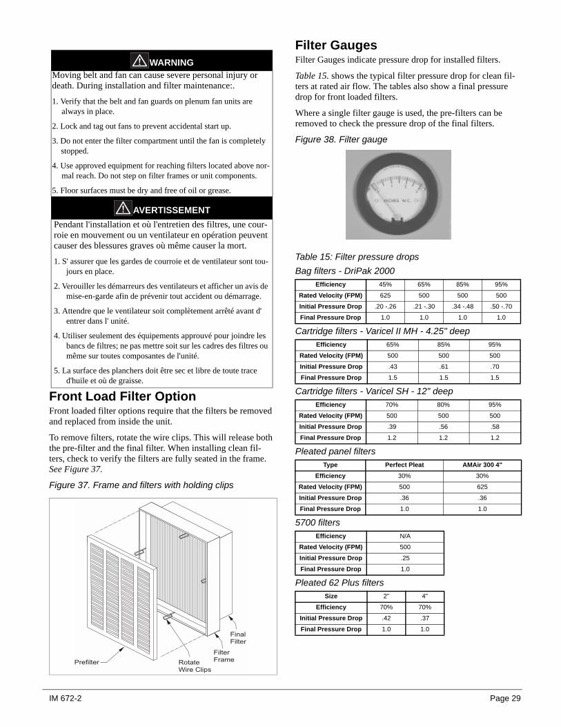
Front Load Filter OptionFront loaded filter options require that the filters be removed and replaced from inside the unit.
To remove filters, rotate the wire clips. This will release both the pre-filter and the final filter. When installing clean fil-ters, check to verify the filters are fully seated in the frame. See Figure 37.
Figure 37. Frame and filters with holding clips
Filter GaugesFilter Gauges indicate pressure drop for installed filters.
Table 15. shows the typical filter pressure drop for clean fil-ters at rated air flow. The tables also show a final pressure drop for front loaded filters.
Where a single filter gauge is used, the pre-filters can be removed to check the pressure drop of the final filters.
Figure 38. Filter gauge
Table 15: Filter pressure dropsBag filters - DriPak 2000
Cartridge filters - Varicel II MH - 4.25" deep
Cartridge filters - Varicel SH - 12" deep
Pleated panel filters
5700 filters
Pleated 62 Plus filters
WARNINGMoving belt and fan can cause severe personal injury or death. During installation and filter maintenance:.
1. Verify that the belt and fan guards on plenum fan units are always in place.
2. Lock and tag out fans to prevent accidental start up.
3. Do not enter the filter compartment until the fan is completely stopped.
4. Use approved equipment for reaching filters located above nor-mal reach. Do not step on filter frames or unit components.
5. Floor surfaces must be dry and free of oil or grease.
AVERTISSEMENTPendant l'installation et où l'entretien des filtres, une cour-roie en mouvement ou un ventilateur en opération peuvent causer des blessures graves où même causer la mort.
1. S' assurer que les gardes de courroie et de ventilateur sont tou-jours en place.
2. Verouiller les démarreurs des ventilateurs et afficher un avis de mise-en-garde afin de prévenir tout accident ou démarrage.
3. Attendre que le ventilateur soit complètement arrêté avant d' entrer dans l' unité.
4. Utiliser seulement des équipements approuvé pour joindre les bancs de filtres; ne pas mettre soit sur les cadres des filtres ou même sur toutes composantes de l'unité.
5. La surface des planchers doit être sec et libre de toute trace d'huile et où de graisse.
< � � � �< � � � � � � � �
� � � 0 � � # �
2 � � � �
< � � � � �< � � �
Efficiency 45% 65% 85% 95%
Rated Velocity (FPM) 625 500 500 500
Initial Pressure Drop .20 -.26 .21 -.30 .34 -.48 .50 -.70
Final Pressure Drop 1.0 1.0 1.0 1.0
Efficiency 65% 85% 95%
Rated Velocity (FPM) 500 500 500
Initial Pressure Drop .43 .61 .70
Final Pressure Drop 1.5 1.5 1.5
Efficiency 70% 80% 95%
Rated Velocity (FPM) 500 500 500
Initial Pressure Drop .39 .56 .58
Final Pressure Drop 1.2 1.2 1.2
Type Perfect Pleat AMAir 300 4"Efficiency 30% 30%
Rated Velocity (FPM) 500 625
Initial Pressure Drop .36 .36
Final Pressure Drop 1.0 1.0
Efficiency N/A
Rated Velocity (FPM) 500
Initial Pressure Drop .25
Final Pressure Drop 1.0
Size 2" 4"
Efficiency 70% 70%
Initial Pressure Drop .42 .37
Final Pressure Drop 1.0 1.0
IM 672-2 Page 29

Coil Maintenance1. The coil must be clean to obtain maximum performance.
Check once a year under normal operating conditions and, if dirty, brush or vacuum clean. Use a chemical coil cleaner on multiple row coils. Read and follow the chemi-cal cleaner’s instructions as some cleaners may contain harsh chemicals. Take care not to damage fins while cleaning. Caution: Fin edges are sharp.
2. Drain pans in any air conditioning unit may have some moisture. Algae, etc., will grow due to airborne spores and bacteria. Periodic cleaning is necessary to prevent this build-up from plugging the drain and causing the drain pan to overflow. Also, the drain pans should be kept clean to prevent the spread of disease. Cleaning should be per-formed by qualified personnel.
3. Dirt and lint can clog the condensate drain, especially with dirty filters. Inspect twice a year to help avoid overflow.
Component Removal and ReplacementPanel RemovalTo remove a side or top panel, remove the flat head fasteners located along the sides of the panel. Once all fasteners are removed, lift the panel off
Frame Channel RemovalFrame channels that run the length of the unit along the top can be removed to allow access to both the side and top of the unit. To remove the frame channel, any adjoining side panel(s) must first be removed. Once the side panel is off, remove the flat head fasteners in the corner of the frame channels. The frame channel can then be pulled out the side. If any top panel fastens into the frame channel (when the frame channel is 24" or wider in direction of air flow), there will be fasteners in the top panel that must be removed before the channel can be pulled out.
Fan SectionThe fan shaft, motor, and any drive components can be removed and replaced through the access door opening. If required, the side panel can be removed for additional access.
If fan replacement is required, the entire fan assembly can be pulled out the side of the cabinet. The fan assembly includes the fan housing, the bearing support, and the fan base.
To remove the fan assembly, remove the side panels and any intermediate supports (follow instructions for side panel removal). Once the panels and any intermediate supports are removed, disconnect the neoprene bulk head seal that is attached to the fan discharge. Remove the four discharge angles that hold the neoprene canvas in place around the dis-charge opening. Then disconnect the fan sled from each of the corner mounts and pull the entire assembly out the side of the unit. After the fan sled is out, loosen the fan bearings and pull out the shaft. Disconnect the fan housing from the fan sled, and bearing support by removing the attaching bolts.
Replace the new fan, re-connect the shaft and bearings and put the fan assembly in the cabinet. Replace panels and fas-teners.
Coil Removal and ReplacementThe coil can be removed by the side, top, or a combination of both. The size and configuration of the coil will affect how the coil can be removed. Single banks of coil are only fas-tened on the connection side of the unit. Stacked and stag-gered coils are fastened on both ends of the coil. See the following instructions for the details to remove each coil type.
Before the coil can be removed, all piping must be discon-nected. The following instructions assume the coil is mounted in a sectionalized coil section, where the frame channel can be removed without affecting other components. If the coil section is unitized with other components, remov-ing the top frame channel will require removal of additional panels.
Removing Single coilsNote: Single coils are bolted to the unit on the connection end. The connection end is held in place with a clamp.
1. Disconnect all piping and remove the brass plugs for the vents and drains located in the connections. Remove all screws and remove the access panel.
2. Remove the screws holding the coil in place then lift and pull the coil out the side.
Installing Single Coils1. Slide the coil through the opening in the coil section onto
the bottom coil rests. Coils must be placed up against the coil bulkheads to prevent any air bypass around the coil. Once the coil is in place, fasten coil to the section. Caulk the seams between the coil casings and bulkheads. See Figure 39.
2. If this is an additional coil being installed and not a replacement, you must locate the coil supply and return connections dimensionally. Carefully drill holes in the end panels of the unit.
3. Remove the brass plugs for the vents and drains on the connections. Slip the panel over the connections. Replace the brass plugs and panel fasteners.
WARNING CLEAN DRAIN PAN REGULARLY SO MOLD DOES NOT DEVELOP.
AVERTISSEMENT Pour eviter la moisissure Nettoyer regulierement le bassin de recuperage.
Page 30 IM 672-2

Removing Stacked CoilsNote: Top and bottom stacked coils are held together with steel plate and screws on one side and drain trough and screws on the other side. Remove the plate and trough before removing the coils. The coils cannot be removed attached together. See Figure 40.
1. Disconnect all piping and remove the brass plugs for the vents and drains located in the connections. Remove all screws and remove the access panel.
2. Remove the bolts holding the coil in place then lift and pull the coil out the side.
3. Remove the steel plate and the drain trough that hold thecoils together.
4. Remove the bolts on both ends of the top coil holding it inplace, then lift and slide the coil out.
5. Remove the bolts on both ends of the bottom coil holdingit in place, then lift and slide the coil out.
Figure 39. Single coil removal
Installing Stacked Coils1. Slide the bottom coil through the opening in the coil sec-
tion onto the bottom coil rests. The coil must be placed up against the coil bulkheads to prevent any air bypass around the coil. Once the coil is in place, bolt the coil to the section.
2. Slide the bottom coil through the opening. The coil must be placed up against the coil bulkheads to prevent any air bypass around the coil. Once the coil is in place, bolt the coil to the section.
3. Caulk the mounting surface of the steel plate and installthe plate on the coils.
4. Caulk the mounting surface of the drain trough and installthe drain trough on the coils.
5. Caulk the seams between the coil casings and blockoffs.
6. Connect all piping and install the brass plugs for the ventsand drains located in the connections. Install the accesspanel.
Figure 40. Locations of plate and trough - stacked coils
Removing and Installing Staggered CoilsStaggered coils have two banks of coils positioned a few inches apart in the direction of airflow. Both coils are secured to the unit on the connection and opposite connection end of the unit.
1. Disconnect all piping and remove the brass plugs for the vents and drains located in the connections.
2. Panels on both the connection and opposite connectionend of the coil section need to be removed to access boltsholding the coils in place. Each coil is held in place withbolts located in the corners of the coil side plates. Removethe bolts then lift and pull the coil out the side.
3. The bottom coil is fastened to the air block off plate. Thescrews attaching this plate to the coil must also beremoved. Once fasteners holding the coil in place areremoved, the coil can be pulled out either side of the unit.
4. Install coils in reverse order of removal.
Coil
Connectionend
Coil
Oppositeconnection
end
Plate
Trough
Apply Caulkto Mounting Surface BeforeInstalling
IM 672-2 Page 31

WarrantyConsult your local McQuay Representative for warranty details. Refer to Form 933-43285Y. To find your local McQuay Representative, go to www.mcquay.com.
Warranty Return Material ProcedureDefective material may not be returned without permission of authorized factory service personnel of McQuay Interna-tional in Minneapolis, Minnesota, (763) 553-5330. A "Return Goods" tag must be included with the returned material. Enter the required information to expedite handling and prompt issuance of credits. All parts must be returned to the appropriate McQuay facility, designated on the "Return Goods" tag. Transportation charges must be prepaid.
The return of the part does not constitute an order for replacement. Therefore, a purchase order must be entered
through the nearest McQuay representative. The order should include part number, model number, and serial number of the unit involved.
Credit will be issued on customer's purchase order following an inspection of the return part and upon determination that the failure is due to faulty material or workmanship during the warranty period.
Replacement PartsWhen writing to McQuay for service or replacement parts, refer to the model number and serial number of the unit as stamped on the serial plate attached to the unit. If replace-ment parts are required, mention the date of installation of the unit and date of failure, along with an explanation of the malfunctions and a description of the replacement parts required.
© 2002 McQuay International • www.mcquay.com • 800-432-1342
This document contains the most current product information as of this printing. For the most up-to-dateproduct information, please go to www.mcquay.com.
Related Documents