1 INSTALLATION AND MAINTENANCE MANUAL FOR ELECTRIC FIRE PUMP CONTROLLERS MODEL GPX

Welcome message from author
This document is posted to help you gain knowledge. Please leave a comment to let me know what you think about it! Share it to your friends and learn new things together.
Transcript

1
INSTALLATION AND MAINTENANCE MANUAL FOR
ELECTRIC FIRE PUMP CONTROLLERS
MODEL GPX
2
4. Home
5. Alarms
3. Main Features
1. Introduction
Table of Contents
10. Language
GPXV2-Manual-EN v2.0.0.0
11. Technical Documents
6. Configuration
7. History
8. Service
2. Installation
9. Download Manuals

3
Table of Contents
Introduction ...................................................................................................................................................................... 5
Types of Electric Fire Pump Controllers .................................................................................................................... 5
Methods of Starting/Stopping ..................................................................................................................................... 6
Installation ....................................................................................................................................................................... 8
FCC Regulations and Radio Standards Specification (RSS) Rules .......................................................................... 8
Location ...................................................................................................................................................................... 9
Mounting .................................................................................................................................................................... 9
Wiring and Connections ............................................................................................................................................. 9
Water Connections ..................................................................................................................................................... 9
Electrical Wiring ......................................................................................................................................................... 9
Electrical Connections................................................................................................................................................ 9
Energy Consumption .................................................................................................................................................. 9
Sizing.......................................................................................................................................................................... 9
Incoming Power Connections .................................................................................................................................. 10
Motor Connections ................................................................................................................................................... 10
Terminal Strip Descriptions ...................................................................................................................................... 11
Quick Start-Up Guide ............................................................................................................................................... 12
Main Features ............................................................................................................................................................... 19
The ViZiTouch .......................................................................................................................................................... 19
Alarm Bell ................................................................................................................................................................. 19
First Setup ................................................................................................................................................................ 20
Home ............................................................................................................................................................................. 21
Home (Menu) ........................................................................................................................................................... 21
Screen Saver ........................................................................................................................................................... 23
Alarms ........................................................................................................................................................................... 24
Alarms (Menu) .......................................................................................................................................................... 24
Configuration ................................................................................................................................................................. 27
Config (Menu) .......................................................................................................................................................... 27
NumPad Page .......................................................................................................................................................... 28
Date and Time Page ................................................................................................................................................ 29
User Login Page / KeyPad Page ............................................................................................................................. 30
Advanced Configuration Page ................................................................................................................................. 31
Control Timers .......................................................................................................................................................... 31
Alarms ...................................................................................................................................................................... 32
Sensor Selection ...................................................................................................................................................... 33
Outputs ..................................................................................................................................................................... 35
Update Program Page ............................................................................................................................................. 36
Factory Settings ....................................................................................................................................................... 37
Interlock Lockout ...................................................................................................................................................... 37
Inputs........................................................................................................................................................................ 38

4
I/O Card Info ............................................................................................................................................................. 38
Network .................................................................................................................................................................... 39
Reboot ViZiTouch .................................................................................................................................................... 39
History ........................................................................................................................................................................... 40
History (Menu) .......................................................................................................................................................... 40
Events Page ............................................................................................................................................................. 41
Pressure Curves ...................................................................................................................................................... 41
Power Curves ........................................................................................................................................................... 42
Saved Logs .............................................................................................................................................................. 43
Pump Curves ........................................................................................................................................................... 44
Statistic ..................................................................................................................................................................... 45
All Time Statistics ..................................................................................................................................................... 45
First Service Statistics .............................................................................................................................................. 46
Last Service Statistics .............................................................................................................................................. 47
Download ................................................................................................................................................................. 47
Service .......................................................................................................................................................................... 48
Download Manuals ........................................................................................................................................................ 49
Language ...................................................................................................................................................................... 50
5
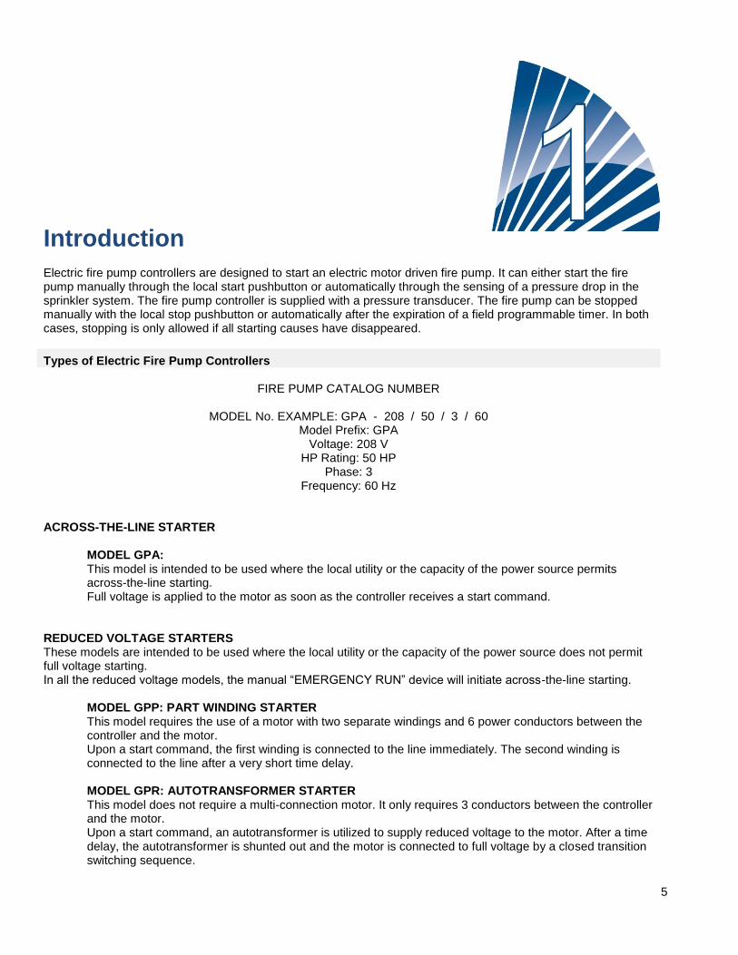
Introduction Electric fire pump controllers are designed to start an electric motor driven fire pump. It can either start the fire pump manually through the local start pushbutton or automatically through the sensing of a pressure drop in the sprinkler system. The fire pump controller is supplied with a pressure transducer. The fire pump can be stopped manually with the local stop pushbutton or automatically after the expiration of a field programmable timer. In both cases, stopping is only allowed if all starting causes have disappeared.
Types of Electric Fire Pump Controllers
FIRE PUMP CATALOG NUMBER
MODEL No. EXAMPLE: GPA - 208 / 50 / 3 / 60 Model Prefix: GPA
Voltage: 208 V HP Rating: 50 HP
Phase: 3 Frequency: 60 Hz
ACROSS-THE-LINE STARTER MODEL GPA:
This model is intended to be used where the local utility or the capacity of the power source permits across-the-line starting. Full voltage is applied to the motor as soon as the controller receives a start command.
REDUCED VOLTAGE STARTERS These models are intended to be used where the local utility or the capacity of the power source does not permit full voltage starting. In all the reduced voltage models, the manual “EMERGENCY RUN” device will initiate across-the-line starting.
MODEL GPP: PART WINDING STARTER This model requires the use of a motor with two separate windings and 6 power conductors between the controller and the motor. Upon a start command, the first winding is connected to the line immediately. The second winding is connected to the line after a very short time delay. MODEL GPR: AUTOTRANSFORMER STARTER This model does not require a multi-connection motor. It only requires 3 conductors between the controller and the motor. Upon a start command, an autotransformer is utilized to supply reduced voltage to the motor. After a time delay, the autotransformer is shunted out and the motor is connected to full voltage by a closed transition switching sequence.
6
MODEL GPS: SOLID STATE STARTER This model does not require a multi-connection motor. It only requires 3 conductors between the controller and the motor. Upon a start command, a solid-state starter is utilized to supply a step less ramp-up voltage to the motor until the motor reaches its full speed. At that time, a fully horsepower rated by-pass contactor is energized connecting the motor directly to full voltage and eliminating all heat loss within the solid-state starter. This controller also features a soft motor stopping mode. MODEL GPV: ACCELERATION RESISTOR STARTER This model does not require a multi-connection motor. It only requires 3 conductors between the controller and the motor. Upon a start command, a set of acceleration resistors in each phase is utilized to supply a reduced voltage to the motor. After a time delay, the resistors are shunted out and the motor is connected to full voltage by a closed transition switching sequence. MODEL GPW: WYE-DELTA CLOSED TRANSITION STARTER This model requires a multi-connection motor and 6 conductors between the controller and the motor. Upon a start command, the motor is connected to the line in the wye connection. After a time delay, the motor is reconnected to the line in the Delta configuration applying full voltage to the motor windings by a closed transition switching sequence. The power source does not « see » any open circuit during the transition from wye to delta. MODEL GPY: WYE-DELTA OPEN TRANSITION STARTER This type of starter requires a multi-connection motor and 6 conductors between the controller and the motor. Upon a start command, the motor is connected to the line in the Wye connection. After a time delay, the motor is reconnected to the line in the Delta configuration applying full voltage to the motor windings. This controller is of the open transition type. The motor is disconnected from the line during the transition from start (wye) to run (delta) mode.
Methods of Starting/Stopping
The controllers are available as combination automatic / non-automatic with provision for manual or automatic shutdown (an automatic shutdown is only possible after an automatic start). METHODS OF STARTING AUTOMATIC START The controller will start automatically on low pressure detection by the pressure sensor when the pressure drops below the cut-in threshold. MANUAL START The motor can be started by pressing the START push button, regardless of the system pressure. REMOTE MANUAL START The motor can be started from a remote location by momentarily closing a contact of a manual push button. REMOTE AUTOMATIC START, DELUGE VALVE START The motor can be started from a remote location by momentarily opening a contact connected to an automatic device. EMERGENCY START The motor can be started manually by using the emergency handle. This handle can be maintained in a closed position. Important: to avoid damaging the contactor, it is recommended to start the motor in this manner: 1) Shutdown the main power by using the main disconnect means, 2) Pull the emergency handle and lock it in closed position,

7
3) Turn the power back on by using the main disconnect means. SEQUENTIAL START In case of a multiple pump application, it may be necessary to delay the automatic (pressure drop) starting of each motor to prevent simultaneous starting of all motors. FLOW START, HIGH ZONE START The pump can be started by opening/closing a contact on the FLOW/ZONE START/STOP input. WEEKLY START The engine can be started (and stopped) automatically at the preprogrammed time. TEST START The motor can be started manually by pressing the run test button. METHODS OF STOPPING MANUAL STOP Manual stop is done by pressing the priority STOP push button. Note that pressing the stop push button will prevent the motor from restarting as long as the button is pressed, plus a two second delay. AUTOMATIC STOP Automatic stop is possible only after an automatic start and this function has been activated. When this function is enabled, the motor is automatically stopped 10 minutes after the restoration of the pressure (above the cut-out threshold) given that no other run cause is present. FLOW STOP, HIGH ZONE STOP If the controller has been started by the FLOW/ZONE START/STOP input and the signal has returned to normal, the motor will be stopped given that no other run cause is present. EMERGENCY STOP The emergency stop is always possible in any starting condition and is done by using the main disconnecting means located on the door.

8
Installation The GPx electric fire pump controller is cULus listed, FM certified and is intended to be installed in accordance with the latest edition of the Standard of the National Fire Protection Association for the Installation of Centrifugal Fire Pumps, NFPA20 (Centrifugal Fire Pumps) and in the USA, National Electrical Code NFPA 70 in Canada, Canadian Electrical Code, Part 1 others * Local Electrical Codes * *Only American and Canadian applicable codes have been considered during the design of the controllers and the selection of components. Except, in some cases, the controller is also seismic approved and has been tested in accordance with the ICC-ES AC156, IBC 2015, CBC 2016, OSHPD Special Seismic Certification Preapproval – OSP and ASCE 7-10 Chapter 13 standards. Proper installation, anchoring and mounting is required to validate this compliance report. Refer to this manual and drawings to determine the seismic mounting requirements and location of the center of gravity (you may need to contact factory). The equipment manufacturer is not responsible for the specification and performance of anchorage systems. The structural engineer of record on the project shall be responsible for anchorage details. The equipment installation contractor shall be responsible for ensuring the requirements specified by the structural engineer of record are satisfied. If detailed seismic installation calculations are required, please contact the manufacturer for the performance of this work.
FCC Regulations and Radio Standards Specification (RSS) Rules To comply with FCC and Industry Canada RF exposure compliance requirements, a separation distance of at least 20 cm must be maintained between the antenna of this device and all nearby persons. This device must not be co-located or operating in conjunction with any other antenna or transmitter. This device complies with Industry Canada licence-exempt RSS standard(s). Operation is subject to the following two conditions: (1) this device may not cause interference, and (2) this device must accept any interference, including interference that may cause undesired operation of the device. This device complies with part 15 of the FCC Rules. Operation is subject to the following two conditions: (1) This device may not cause harmful interference, and (2) this device must accept any interference received, including interference that may cause undesired operation. Note: This equipment has been tested and found to comply with the limits for a Class A digital device, pursuant to part 15 of the FCC Rules. These limits are designed to provide reasonable protection against harmful interference when the equipment is operated in a commercial environment. This equipment generates, uses, and can radiate radio frequency energy and, if not installed and used in accordance with the instruction manual, may cause harmful interference to radio communications. Operation of this equipment in a residential area is likely to cause harmful interference in which case the user will be required to correct the interference at his own expense. “Changes or modifications not expressly approved by the party responsible for compliance could void the user's authority to operate the equipment.”
9
Location The controller shall be located as close as practical to the motor it controls and shall be within sight of the motor. The controller shall be located or protected so that it will not be damaged by water escaping from the pump or pump connections. Current carrying parts of the controller shall be not less than 12 in. (305 mm) above the floor level. Working clearances around the controller shall comply with NFPA 70, National Electrical Code, Article 110 or C22.1, Canadian Electrical Code, Article 26.302 or other local codes. The controller is suitable for use in locations subject to a moderate degree of moisture, such as a damp basement. The pump room ambient temperature shall be between 39°F (4°C) and 104°F (40°C). The standard controller enclosure is rated NEMA 2. It is the installer's responsibility to insure that either the standard enclosure meets the ambient conditions or that an enclosure with an appropriate rating has been provided. Controllers must be installed inside a building and they are not designed for outside environment. The paint color may change if the controller is exposed to ultraviolet rays for a long period of time.
Mounting The fire pump controller shall be mounted in a substantial manner on a single incombustible supporting structure. Wall mounted controllers shall be attached to the structure or wall using all four (4) mounting ears provided on the controller with hardware designed to support the weight of the controller at a height not less than 12 in. (305 mm) above floor level. Floor mounted controllers shall be attached to the floor using all holes provided on the mounting feet with hardware designed to support the weight of the controller. The mounting feet provide the necessary 12 in. (305 mm) clearance for current carrying parts. For seismic applications, the mounting arrangement should be rigid wall and base only. The structural engineer of record on the project shall be responsible for anchorage details.
Wiring and Connections
Water Connections The controller must be connected to the pipe system according to the latest edition of NFPA20 and also to a drain pipe. The water connections are on the left side of the controller. The connection to the system pressure is a Male ½ NPT. If a drain is present, the connection to the drain is a tapered connection for plastic tubing.
Electrical Wiring The electrical wiring between the power source and the fire pump controller shall meet the latest edition of NFPA 20, NFPA 70 National Electrical Code Article 695 or C22.1 Canadian Electrical Code, Section 32-200 or other local codes. Electrical wiring shall be typically sized to carry at least 125% of the full load current (FLC or FLA) of the fire pump motor.
Electrical Connections A licensed electrician must supervise the electrical connections. The dimension drawings show the area suitable for incoming power and motor connections. No other location shall be used. Only watertight hub fittings shall be used when entering the cabinet to preserve the NEMA rating of the cabinet. The installer is responsible for adequate protection of the fire pump controller components against metallic debris or drilling chips. Failure to do so may cause injuries to personnel, damage the controller and subsequently void warranty.
Energy Consumption Standby power: 10W
Sizing Incoming power terminals on the controller are suitable to accept wire based on that selection with insulation not less than 60°C. (Refer to terminal diagram for terminal sizes.) The electrical wiring between the fire pump controller and the pump motor shall be in rigid, intermediate, or liquid tight flexible metal conduit or Type MI cable and meet the requirements of NFPA 70 National Electrical Code or C22.1 Canadian Electrical Code or other local codes. The number of conductors required varies depending on the model of starter: 3-wires plus ground sized at 125% of full load current for models GPA, GPR, GPS and GPV.

10
6-wires plus ground sized at 125% of 50% of the motor full load current for GPP model. 6-wires plus ground sized at 125% of 58% of the motor full load current for GPY and GPW models.
Incoming Power Connections Incoming normal power is to be connected to terminals located on the disconnecting means CB. - For 3 phases motor: identified L1-L2 and L3. - For single phase motor: identified L1 and L3
Motor Connections Motor wires shall be connected to terminals identified by: - T1-T2 and T3 located on main contactor (1M) for models GPA, GPR, GPS and GPV - T1-T2 and T3 located on contactor (1M) and T7-T8 and T9 located on contactor (2M) for model GPP - T1-T2 and T3 located on contactor (1M) and T6-T4 and T5 located on contactor (2M) for models GPY and GPW It is the responsibility of the installer to obtain connection information on the motor and to assure that the motor is connected as per the motor manufacturer recommendations. Failure to do so may cause injuries to personnel, damage the motor and/or the controller and subsequently void warranty on both items.
11
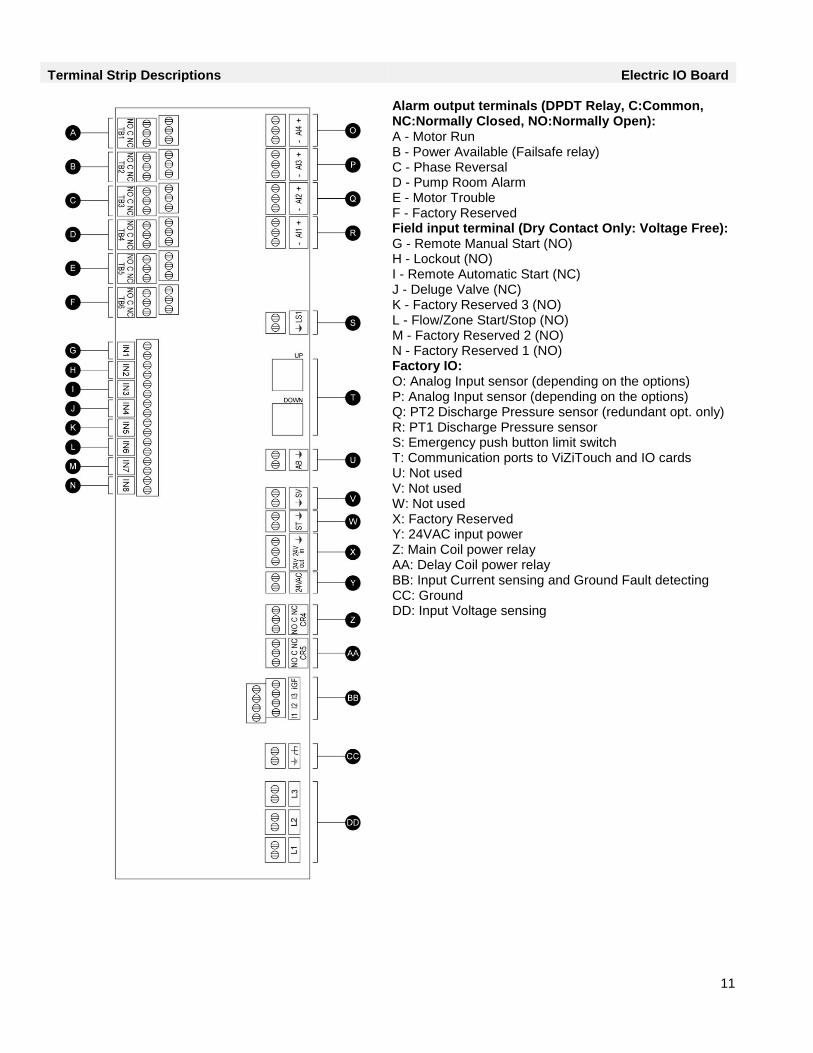
Terminal Strip Descriptions Electric IO Board Alarm output terminals (DPDT Relay, C:Common, NC:Normally Closed, NO:Normally Open): A - Motor Run B - Power Available (Failsafe relay) C - Phase Reversal D - Pump Room Alarm E - Motor Trouble F - Factory Reserved Field input terminal (Dry Contact Only: Voltage Free): G - Remote Manual Start (NO) H - Lockout (NO) I - Remote Automatic Start (NC) J - Deluge Valve (NC) K - Factory Reserved 3 (NO) L - Flow/Zone Start/Stop (NO) M - Factory Reserved 2 (NO) N - Factory Reserved 1 (NO) Factory IO: O: Analog Input sensor (depending on the options) P: Analog Input sensor (depending on the options) Q: PT2 Discharge Pressure sensor (redundant opt. only) R: PT1 Discharge Pressure sensor S: Emergency push button limit switch T: Communication ports to ViZiTouch and IO cards U: Not used V: Not used W: Not used X: Factory Reserved Y: 24VAC input power Z: Main Coil power relay AA: Delay Coil power relay BB: Input Current sensing and Ground Fault detecting CC: Ground DD: Input Voltage sensing

12
Quick Start-Up Guide
The rating label is the most important label. It must be read carefully to ensure the compatibility between the controller and the installation.
Verify that the controller is installed securely on the wall, or optionally on the mounting stand.
13
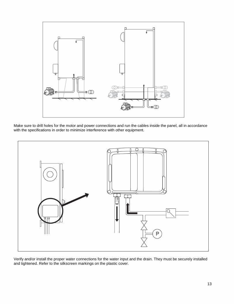
Make sure to drill holes for the motor and power connections and run the cables inside the panel, all in accordance with the specifications in order to minimize interference with other equipment.
Verify and/or install the proper water connections for the water input and the drain. They must be securely installed and tightened. Refer to the silkscreen markings on the plastic cover.

14
Connect the input power and the motor on their respective terminals. Secure with the appropriate torque as indicated on the torque label and verify all connections. Secure the door in closed position then put the circuit breaker disconnecting means in ON position. Verify the readings on the controller main screen.
Once the controller has booted up the “First Start Up” page appears. Press “User Login” and enter a valid authorization code. Once logged in, press “Power”.

15
Verify that the normal voltage shown at L1-L2, L2-L3 and L1-L3 (nominal) is the same as what is written on the fire pump controllers nameplate. The fire pump controller will validate the nominal voltage automatically versus what it has been built for. If all is adequate green check marks will appear. To continue to next step, press “ ˂ First Start Up “
Press “Motor Rotation” Press the “Start” button to start the electric motor and validate that the electric motor is rotating in the correct direction. If it is not rotating in the correct direction adjus the motor connections as per below. Press the “Stop” button to stop the electric motor.

16
If or once the electric motor is rotating in the correct direction, check off the “Motor Rotation” box. To continue to next step, press “ ˂ First Start Up “.
Press “Pressure”. - Verify that the pressure reading on the screen matches with the calibrated pressure gauge installed on the sensing line. - Choose the desired units of measurement for pressure reading. - Adjust, if required, the range of the digital pressure gauge at Max. Pres. - Insert the Cut-Out and Cut-In pressure values of the fire pump. - Insert, if so desired, the Cut-Out and Cut-In pressure values of the jockey pump. Note: The jockey pump Cut-Out and Cut-In values must be set at the jockey pump controller itself. Inserting these values at the Fire Pump Controller is only for pressure recording data purposes. To continue to next step, press “ ˂ First Start Up “.

17
Press “Other Configuration” button. - Adjust, if required, the Date and Time. - If the installation requires the Automatic Shutdown feature, select by pressing the check box and adjust the duration of the minimum run period timer. - If the installation requires the Periodic Test feature, select by pressing the check box. Adjust the frequency of testing, the day, the start time and the duration of the test. - Adjust the Run Test duration timer. This is the last step. If “Power”, “Motor Rotation” and “Pressure” have green check marks, press “Service Done”. The controller will be placed in Automatic Operation. The “Home” page will appear.
From the “Home” page, verify that the displayed values are correct.

18
The “First Start up” is now completed. The controller is fully installed and configured.
19
Main Features The ViZiTouch
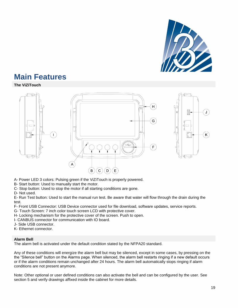
A- Power LED 3 colors: Pulsing green if the ViZiTouch is properly powered. B- Start button: Used to manually start the motor. C- Stop button: Used to stop the motor if all starting conditions are gone. D- Not used. E- Run Test button: Used to start the manual run test. Be aware that water will flow through the drain during the test. F- Front USB Connector: USB Device connector used for file download, software updates, service reports. G- Touch Screen: 7 inch color touch screen LCD with protective cover. H- Locking mechanism for the protective cover of the screen. Push to open. I- CANBUS connector for communication with IO board. J- Side USB connector. K- Ethernet connector.
Alarm Bell The alarm bell is activated under the default condition stated by the NFPA20 standard. Any of these conditions will energize the alarm bell but may be silenced, except in some cases, by pressing on the the “Silence bell” button on the Alarms page. When silenced, the alarm bell restarts ringing if a new default occurs or if the alarm conditions remain unchanged after 24 hours. The alarm bell automatically stops ringing if alarm conditions are not present anymore. Note: Other optional or user defined conditions can also activate the bell and can be configured by the user. See section 5 and verify drawings affixed inside the cabinet for more details.

20
First Setup The First Setup must be done prior to using the controller. Completing the First Setup is the only way to access the homepage and enable the automatic mode of the controller.
21
Home Home (Menu) Home
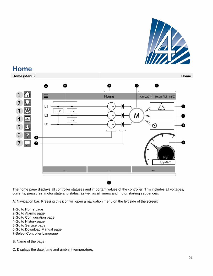
The home page displays all controller statuses and important values of the controller. This includes all voltages, currents, pressures, motor state and status, as well as all timers and motor starting sequences. A: Navigation bar: Pressing this icon will open a navigation menu on the left side of the screen: 1-Go to Home page 2-Go to Alarms page 3-Go to Configuration page 4-Go to History page 5-Go to Service page 6-Go to Download Manual page 7-Select Controller Language B: Name of the page. C: Displays the date, time and ambient temperature.
1
2
3
4
5
6
7

22
D: Motor power voltage. Each box represents an individual phase voltage between the two adjacent lines. E: Current. Each circle represents an individual line current. F: Motor contacts. An animation shows the contactor opened or closed depending on the signal sent to the main coil. G: The electric motor. It will be grey if the motor is stopped, green if a “Motor Run” signal is detected and red if a “Fail to start” has occurred. Pressing on the motor will redirect the user to the “Last Service Statistics” page, which monitors all relevant statistics concerning the controller since the last service. H: The motor configuration symbol shows how the motor is wired to the contactor(s). This symbol is used to show if the motor is in a starting configuration (Wye wiring, for example) or in a permanent running configuration (i.e. delta wiring)
Permanent delta motor connection.
Temporary wye motor connection.
Temporary auto-transformer motor connection.
Temporary primary resistor motor connection.
Temporary solid state starter motor connection.
Temporary part-winding motor connection. I: Representation of the motor starting or stopping cause. The reason why the motor is running will be displayed in a message box. Possible choices include, but are not limited to: EMERGENCY: Manual motor starting activated by the emergency handle. MANUAL: Manual motor starting activated by the START push button. REMOTE MANUAL: Manual motor starting activated by a remote start contact. DELUGE: Automatic motor starting activated by a deluge valve. AUTO: Automatic motor starting activated by pressure drop. REMOTE AUTO: Automatic motor starting activated by remote equipment. FLOW: Automatic motor starting activated by a signal in the FLOW/ZONE START/STOP input. HIGH ZONE: Automatic motor starting activated by a signal in the FLOW/ZONE START/STOP input. WEEK TEST: Automatic motor starting activated by a scheduled test. RUN TEST: Automatic motor starting activated by the run test push button. This message can also indicate the reason why the motor is not running despite the fact that a request is being made. Possible choices include, but are not limited to:

23
LOCKED ROTOR CURRENT (not on GPL models): A locked rotor current alarm has not been cleared on the alarms page and prevents the motor from starting. LOW PRESSURE: A low suction pressure prevents the motor from running, This functionality is optional. LOW WATER: A low water reservoir level prevents the motor from running, This functionality is optional. LOW ZONE: A not running lower zone controller prevents the motor from running. This functionality is optional. LOCKED: An interlock signal is preventing the motor from running. J: Timers. The sequential start timer (on-delay) will start timing upon an Automatic start request (pressure drop, deluge valve or remote auto signal). The motor will only start if the request stays active for the duration of this timer. The “Duration” of the run period timer (off –delay) for automatic shutdown will start timing once the start request disappears. The pump will stop at the expiration of this timer if the starting reason is no longer present. If a periodic test has been programmed, the remaining time will be displayed. If a manual run test has been energized, the remaining time will be displayed. K: The discharge pressure gauge. It allows for a precise reading of the actual system pressure.The Cut-In (between the yellow and the red section) and the Cut-Out (between the green and the yellow section) set point values are indicated on the gauge. These values will also be represented by a red and green line on the gauge, allowing a quick comparison between the actual pressure and the set points. The actual pressure is shown in the centre of the gauge along with the unit of measure (psi, bar etc). The maximum allowable pressure is also indicated on the gauge and will scale the gauge accordingly. A full screen image of the gauge will appear by pressing anywhere on the gauge. L: Status Bar. The Status Bar appears across the bottom of the display. It displays three statuses that describe the primary configuration of the controller: Pressure actuated or Non-pressure Actuated, Automatic Controller or Non-automatic, Manual or Automatic Shutdown. If an alarm or a warning is active, a colored rectangle will appear over the Status Bar and will display the error message. This notification will be yellow for a warning and red for an alarm. If more than one error is active, the display will alternate between the error messages. The messages will disappear when the alarm or warning starting cause is no longer present.
Screen Saver After 5 minutes of inactivity on the ViZiTouch, the screen will dim it's brightness to 25%. After 10 minutes of inactivity on the ViziTouch, the “Black Screen” screen saver will activate. Its goal is to expand the lifetime of the LCD screen. The screen saver will be instantly deactivated if the engine is running or if an alarm is activated. To manually deactivate it, simply touch the screen or any membrane button. After deactivation, the screen saver will always redirect to the “Home” page. It will also log off any user by resetting the security level to 0 and save any new modifications to the settings.
24
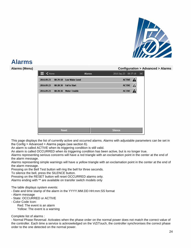
Alarms Alarms (Menu) Configuration > Advanced > Alarms
This page displays the list of currently active and occurred alarms. Alarms with adjustable parameters can be set in the Config ˃ Advanced ˃ Alarms pages (see section 6). An alarm is called ACTIVE when its triggering condition is still valid. An alarm is called OCCURRED when its triggering condition has been active, but is no longer true. Alarms representing serious concerns will have a red triangle with an exclamation point in the center at the end of the alarm message. Alarms representing simple warnings will have a yellow triangle with an exclamation point in the center at the end of the alarm message. Pressing on the Bell Test button will ring the bell for three seconds. To silence the bell, press the SILENCE button. Pressing on the RESET button will reset OCCURRED alarms only. Alarms ending with ** are available on transfer switch models only The table displays system events: - Date and time stamp of the alarm in the YYYY.MM.DD HH:mm:SS format - Alarm message - State: OCCURRED or ACTIVE - Color Code Icon: Red: The event is an alarm Yellow: The event is a warning Complete list of alarms : - Normal Phase Reversal: Activates when the phase order on the normal power does not match the correct value of the controller. Each time a service is acknowledged on the ViZiTouch, the controller synchronises the correct phase order to the one detected on the normal power.
25
- Phase Loss N1: This alarm is activated if the first phase of the normal power connection does not meet the qualification criteria. - Phase Loss N2: Activates if the second phase of the normal power connection does not meet the qualification criteria. - Phase Loss N3: Activates if the third phase of the normal power connection does not meet the qualification criteria. - Lock Rotor Current: Activates when a lock rotor condition has been detected on the normal power. Note that the motor will not be permitted to start on the normal power as long as this alarm has not been reset from the alarms page. - Fail to start: Activates if there is and under-current draw of two phases when the motor should be running. A 20 second factory set delay is used to give the motor enough time to start before signalling this alarm. - Automatic Transfer Sw. Trouble**: After a factory programmed delay, activates upon detection of any of the following transfer switch data: The alternate position and normal position limit switches are both activated OR none of the alternate position or the normal position limit switches are activated OR the voltage reading on the load side of the motor contactor does not match the reported input power . - Loss of power: Activates when a complete loss of normal power is detected. - Service Required: Activates when service is due for the controller. This occurs when the date set in the service page has passed or if no service has ever been done. - Undercurrent: Activates when current is under 30% of FLA and the motor has been running for 15 seconds. - Overcurrent: Activates when current is above 150% of FLA. - Undervoltage: Activates when normal power voltage is below 80% of nominal voltage. - Overvoltage: Activates when normal power voltage is above 115% of nominal voltage. - Phase Unbalanced: Activates when there is a difference of more than 10% of nominal voltage between the normal power voltage readings. - Weekly Test Cut-In Not Reached: Activates if the Cut-In is not reached during a manual or weekly test. At the end of the 20s timer, if the Cut-In is not reached, the test may still be successful at starting the motor if the pressure has dropped by at least 5 PSI. - WT Check WT Solen: Activates if the pressure does not drop a minimum of 5 PSI during the manual run test or the weekly test. Indicates a failure with the Test Solenoid Valve. - PT Fault Detected: Occurs if the pressure reading is out of its normal range. Additionnally, if an optional dual pressure sensor is installed, it will be activated if the two pressure transducers show different readings. Further investigation is advised to determine what caused the different readings. Note that the controller will always choose the lowest pressure reading to determine the actual system pressure. Also, if the voltage powering the transducer is below 0.5V or over 4.5V the alarm will be activated. - Alternate Power Phase Reversal**: Activates when the phase order on the alternate power does not match the correct value of the controller. Each time a service is acknowledged on the ViZiTouch, the controller synchronises the correct phase order to the one detected on the normal power. - Alternate IS Tripped/Opened**: Activates when the AIS is either tripped or opened. This alarm condition rings the bell and cannot be silenced. - Alternate CB Tripped/Opened**: Activates when the ACB is either tripped or opened. This alarm condition rings

26
the bell and cannot be silenced. - I/O Electric Communication Error: Activates if no communication between the ViZiTouch and the electric I/O card could be established for 15 seconds. This alarm is critical and triggers the bell as well as deactivating the failsafe Power Available output relay. If this alarm persists for more than 1 minute, the controller will reboot to try to fix the problem. - I/O Transfer Switch Communication Error**: Activates if no communication with the transfer switch I/O card could be established for 15 seconds. This alarm is critical and triggers the bell bell as well as deactivating the failsafe Power Available output relay. If this alarm persists for more than 1 minute, the controller will reboot to try to fix the problem. - Alternate Side LRC**: Activates when a lock rotor condition has been detected on the alternate power. Note that the motor will not be permitted to start on the alternate power as long as this alarm has not been reset from the alarms page. - Low ambient temperature: Activates when the ambient temperature is below the factory set value (5° Celsius). - Control Voltage Not Healthy: Activates when the 24VAC power input to the I/O cards is below the acceptable functional range. - Motor Trouble: Activates when a motor related alarm condition is present (overcurrent, undercurrent, fail to start or ground fault). - Pump Room Alarm: Activates when a pump room related alarm condition is present (overvoltage, undervoltage, phase unbalanced). - Pump on demand: Activates when the pressure is below the cut-in set-point on an automatic pressure actuated controller. - Invalid Cut-In: Activates when the Cut-In value is not acceptable on a pressure actuated cont
27
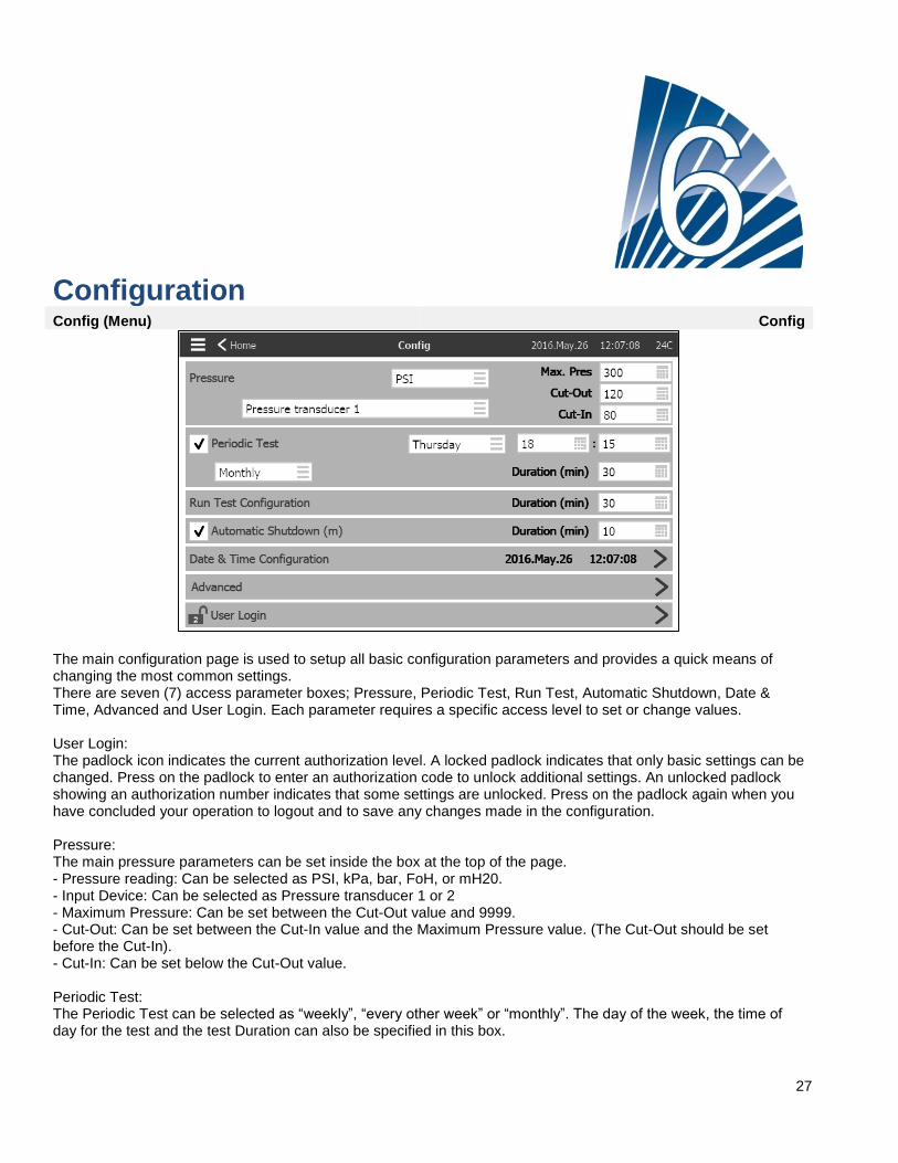
Configuration Config (Menu) Config
The main configuration page is used to setup all basic configuration parameters and provides a quick means of changing the most common settings. There are seven (7) access parameter boxes; Pressure, Periodic Test, Run Test, Automatic Shutdown, Date & Time, Advanced and User Login. Each parameter requires a specific access level to set or change values. User Login: The padlock icon indicates the current authorization level. A locked padlock indicates that only basic settings can be changed. Press on the padlock to enter an authorization code to unlock additional settings. An unlocked padlock showing an authorization number indicates that some settings are unlocked. Press on the padlock again when you have concluded your operation to logout and to save any changes made in the configuration. Pressure: The main pressure parameters can be set inside the box at the top of the page. - Pressure reading: Can be selected as PSI, kPa, bar, FoH, or mH20. - Input Device: Can be selected as Pressure transducer 1 or 2 - Maximum Pressure: Can be set between the Cut-Out value and 9999. - Cut-Out: Can be set between the Cut-In value and the Maximum Pressure value. (The Cut-Out should be set before the Cut-In). - Cut-In: Can be set below the Cut-Out value. Periodic Test: The Periodic Test can be selected as “weekly”, “every other week” or “monthly”. The day of the week, the time of day for the test and the test Duration can also be specified in this box.
28
Run Test Configuration: The Run Test Configuration box is where the duration of the run test time is set. A timer between 1 and 30 minutes can be selected. Automatic Shutdown: If enabled, the Automatic Shutdown will automaticly stop the pump after the demand dissapears. A timer between 1 and 1440 minutes can be selected. Advanced: Go to the advanced configuration pages. Date & Time Configuration: Select to display the Date Time page.
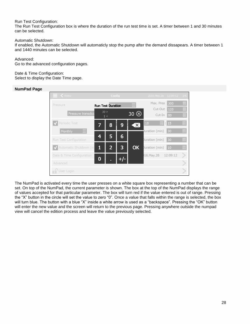
NumPad Page
The NumPad is activated every time the user presses on a white square box representing a number that can be set. On top of the NumPad, the current parameter is shown. The box at the top of the NumPad displays the range of values accepted for that particular parameter. The box will turn red if the value entered is out of range. Pressing the “X” button in the circle will set the value to zero “0”. Once a value that falls within the range is selected, the box will turn blue. The button with a blue “X” inside a white arrow is used as a “backspace”. Pressing the “OK” button will enter the new value and the screen will return to the previous page. Pressing anywhere outside the numpad view will cancel the edition process and leave the value previously selected.
29
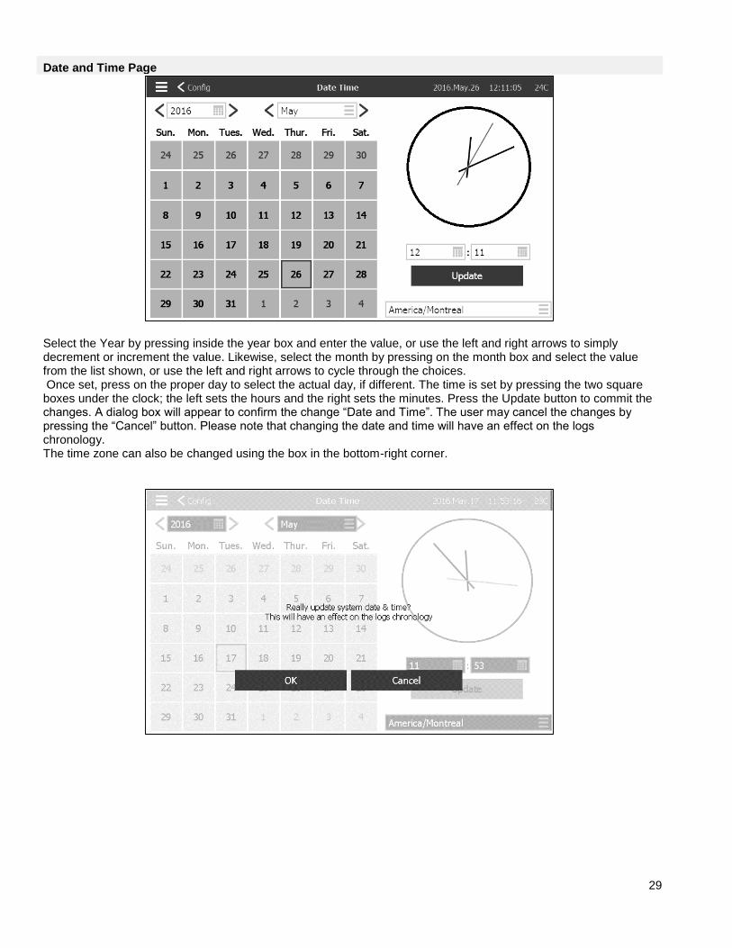
Date and Time Page
Select the Year by pressing inside the year box and enter the value, or use the left and right arrows to simply decrement or increment the value. Likewise, select the month by pressing on the month box and select the value from the list shown, or use the left and right arrows to cycle through the choices. Once set, press on the proper day to select the actual day, if different. The time is set by pressing the two square boxes under the clock; the left sets the hours and the right sets the minutes. Press the Update button to commit the changes. A dialog box will appear to confirm the change “Date and Time”. The user may cancel the changes by pressing the “Cancel” button. Please note that changing the date and time will have an effect on the logs chronology. The time zone can also be changed using the box in the bottom-right corner.
30
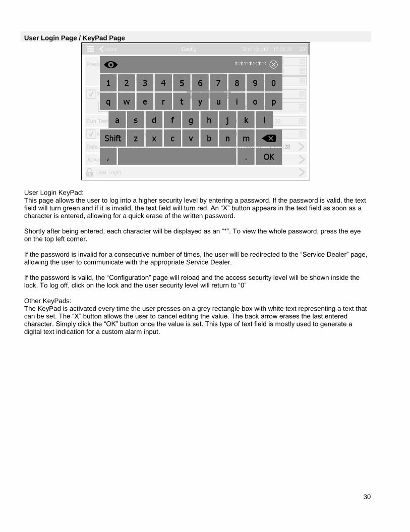
User Login Page / KeyPad Page
User Login KeyPad: This page allows the user to log into a higher security level by entering a password. If the password is valid, the text field will turn green and if it is invalid, the text field will turn red. An “X” button appears in the text field as soon as a character is entered, allowing for a quick erase of the written password. Shortly after being entered, each character will be displayed as an “*”. To view the whole password, press the eye on the top left corner. If the password is invalid for a consecutive number of times, the user will be redirected to the “Service Dealer” page, allowing the user to communicate with the appropriate Service Dealer. If the password is valid, the “Configuration” page will reload and the access security level will be shown inside the lock. To log off, click on the lock and the user security level will return to “0” Other KeyPads: The KeyPad is activated every time the user presses on a grey rectangle box with white text representing a text that can be set. The “X” button allows the user to cancel editing the value. The back arrow erases the last entered character. Simply click the “OK” button once the value is set. This type of text field is mostly used to generate a digital text indication for a custom alarm input.
31
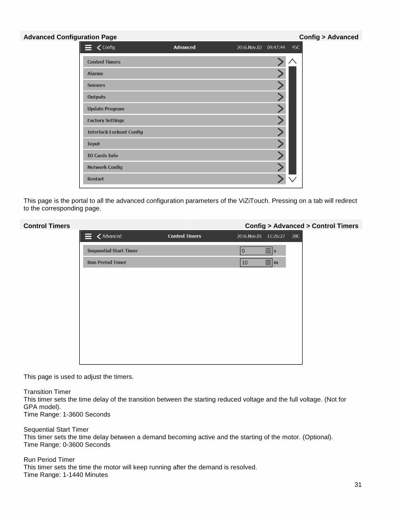
Advanced Configuration Page Config > Advanced
This page is the portal to all the advanced configuration parameters of the ViZiTouch. Pressing on a tab will redirect to the corresponding page.
Control Timers Config > Advanced > Control Timers
This page is used to adjust the timers. Transition Timer This timer sets the time delay of the transition between the starting reduced voltage and the full voltage. (Not for GPA model). Time Range: 1-3600 Seconds Sequential Start Timer This timer sets the time delay between a demand becoming active and the starting of the motor. (Optional). Time Range: 0-3600 Seconds Run Period Timer This timer sets the time the motor will keep running after the demand is resolved. Time Range: 1-1440 Minutes
32
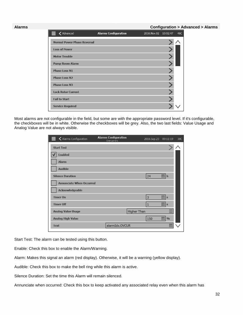
Alarms Configuration > Advanced > Alarms
Most alarms are not configurable in the field, but some are with the appropriate password level. If it's configurable, the checkboxes will be in white. Otherwise the checkboxes will be grey. Also, the two last fields: Value Usage and Analog Value are not always visible.
Start Test: The alarm can be tested using this button. Enable: Check this box to enable the Alarm/Warning. Alarm: Makes this signal an alarm (red display). Otherwise, it will be a warning (yellow display). Audible: Check this box to make the bell ring while this alarm is active. Silence Duration: Set the time this Alarm will remain silenced. Annunciate when occurred: Check this box to keep activated any associated relay even when this alarm has
33
occurred. Acknowledgeable: Check this box to make the alarm acknowledgeable. If an alarm is ackowledged, the bell will be silenced and the alarm IO board Output will stop being active. To acknowledge an alarm, go to the alarm list page and press the blue “Active” status on the right of the alarm. The “Active” status should change to “Acknowledge”. Timer On: It is the time delay between the triggering of the condition and the activation of the alarm. Timer Off: It is the time delay between the stopping of the condition and the deactivation of the alarm. Analog Value Usage: It is used to describe the activation range of the alarm. “Lower Than”, “Higher Than” and “Between” can be selected. The corresponding value has to be entered. Text: This field can be used to change the name of the alarm that will be displayed while this alarm is active. Note that changing the factory set name of an alarm will disable any translation of this alarm to different languages.
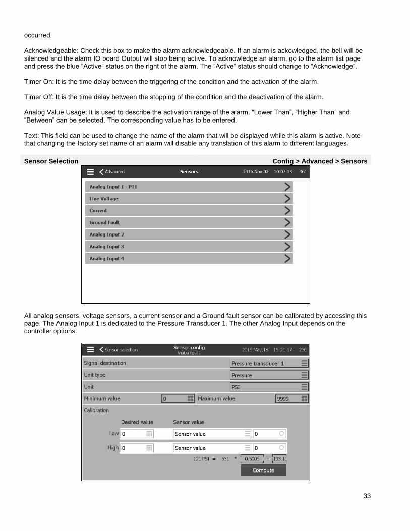
Sensor Selection Config > Advanced > Sensors
All analog sensors, voltage sensors, a current sensor and a Ground fault sensor can be calibrated by accessing this page. The Analog Input 1 is dedicated to the Pressure Transducer 1. The other Analog Input depends on the controller options.

34
Every sensor, except the line Voltage and the Current sensor can be calibrated the same way. The Signal destination, the Unit type, the Unit, the Min and Max value are variables that are set in factory but the calibration can be made in the field. There are three ways of calibrating a sensor that can be chosen in the windows below “Sensor value”. -Sensor value: Connect an external measurement tool that is already calibrated (like a Manometer to calibrate a pressure sensor). Bring the system to calibrate to a low point. While looking at the measurement tool, press the read button (the button with a circular arrow). The value that was displayed on the measurement tool when the read button was pressed needs to be enter in the “Low” window below the Desired value. Repeat these steps with a high value. Then press compute. -Theorical voltage: Use a graphic of the theorical sensor's voltage response (usually given in the datasheet of the sensor). Enter a low point (value, voltage) and a high point. Then press compute. -Theorical current: Same as the theorical voltage, but with amperes. For better results, use two points that are far apart, but in the normal range of the sensor.
To calibrate the line voltage sensor, use an external voltmeter that is already calibrated. With the control panel under power: - Read the voltage between L1 and L2, and press the first white box under “Sensor value”. - Enter the voltages in the first white box below “Desired”. - Read the voltage between L2 and L3, and press the second white box under “Sensor value”. - Enter the voltages in the second white box below “Desired”. - Read the voltage between L1 and L3, and press the third white box under “Sensor value”. - Enter the voltages in the third white box below “Desired”. - Press the “Compute” button.
35
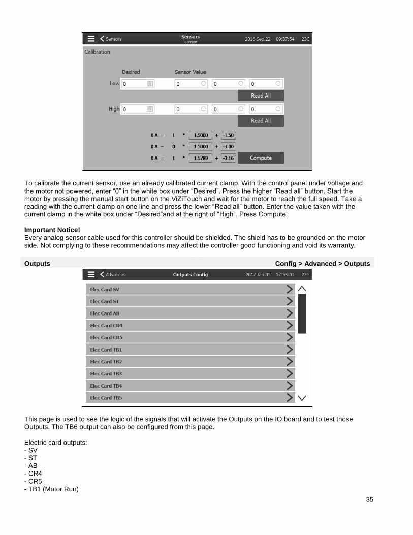
To calibrate the current sensor, use an already calibrated current clamp. With the control panel under voltage and the motor not powered, enter “0” in the white box under “Desired”. Press the higher “Read all” button. Start the motor by pressing the manual start button on the ViZiTouch and wait for the motor to reach the full speed. Take a reading with the current clamp on one line and press the lower “Read all” button. Enter the value taken with the current clamp in the white box under “Desired”and at the right of “High”. Press Compute. Important Notice! Every analog sensor cable used for this controller should be shielded. The shield has to be grounded on the motor side. Not complying to these recommendations may affect the controller good functioning and void its warranty.
Outputs Config > Advanced > Outputs
This page is used to see the logic of the signals that will activate the Outputs on the IO board and to test those Outputs. The TB6 output can also be configured from this page. Electric card outputs: - SV - ST - AB - CR4 - CR5 - TB1 (Motor Run)
36
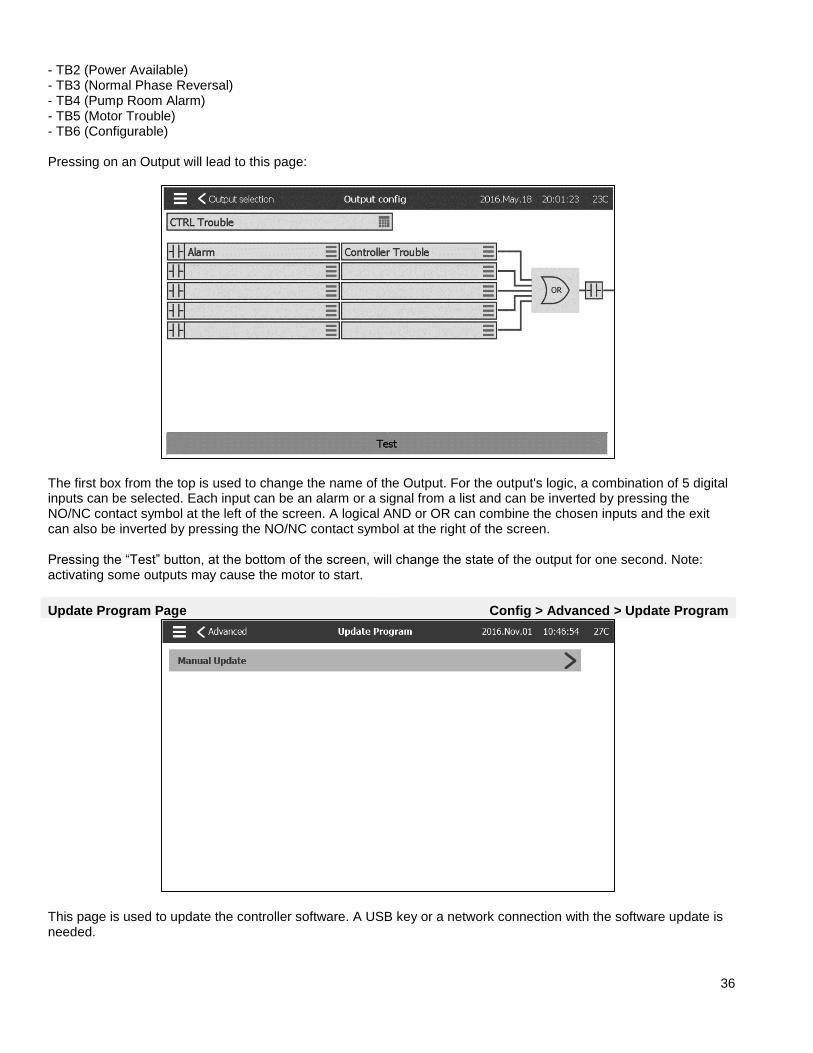
- TB2 (Power Available) - TB3 (Normal Phase Reversal) - TB4 (Pump Room Alarm) - TB5 (Motor Trouble) - TB6 (Configurable) Pressing on an Output will lead to this page:
The first box from the top is used to change the name of the Output. For the output's logic, a combination of 5 digital inputs can be selected. Each input can be an alarm or a signal from a list and can be inverted by pressing the NO/NC contact symbol at the left of the screen. A logical AND or OR can combine the chosen inputs and the exit can also be inverted by pressing the NO/NC contact symbol at the right of the screen. Pressing the “Test” button, at the bottom of the screen, will change the state of the output for one second. Note: activating some outputs may cause the motor to start.
Update Program Page Config > Advanced > Update Program
This page is used to update the controller software. A USB key or a network connection with the software update is needed.
37
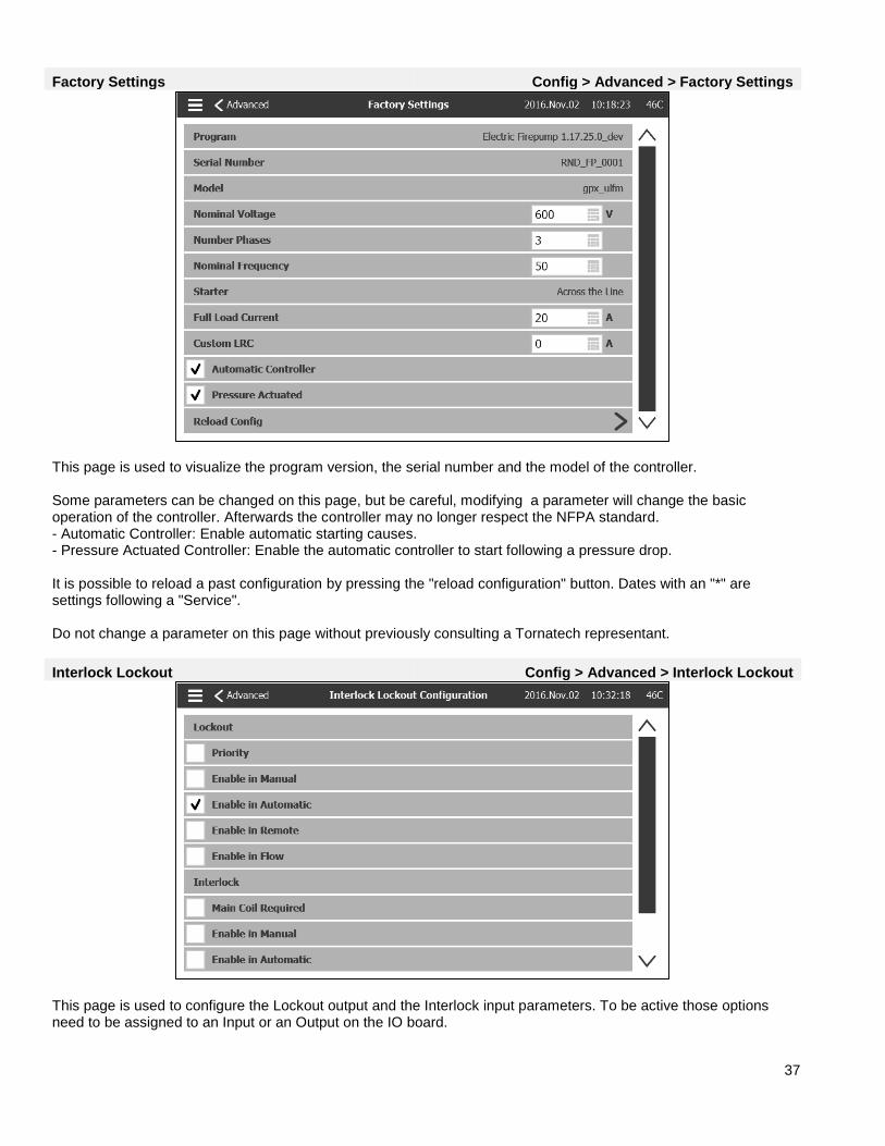
Factory Settings Config > Advanced > Factory Settings
This page is used to visualize the program version, the serial number and the model of the controller. Some parameters can be changed on this page, but be careful, modifying a parameter will change the basic operation of the controller. Afterwards the controller may no longer respect the NFPA standard. - Automatic Controller: Enable automatic starting causes. - Pressure Actuated Controller: Enable the automatic controller to start following a pressure drop. It is possible to reload a past configuration by pressing the "reload configuration" button. Dates with an "*" are settings following a "Service". Do not change a parameter on this page without previously consulting a Tornatech representant.
Interlock Lockout Config > Advanced > Interlock Lockout
This page is used to configure the Lockout output and the Interlock input parameters. To be active those options need to be assigned to an Input or an Output on the IO board.
38
Lockout is an Input that prevents the motor from starting. -Priority: If enabled, the lockout signal will also act as a shutdown. -Enable in Manual: If checked, activation of the lockout input will prevent the Manual start. -Enable in Automatic: If checked, activation of the lockout input will prevent the Automatic start. -Enable in Remote: If checked, activation of the lockout input will prevent the Remote start. -Enable in Flow: If checked, activation of the lockout input will prevent the Flow start. Interlock is an Output that prevents a second motor from starting. -Main coil required: If enabled, the controller will wait to have the main starting coil signal before putting Interlock active. -Enable in manual: If checked, this option will activate the output Interlock on a Manual start. -Enable in auto: If checked, this option will activate the output Interlock on an Automatic start. -Enable in remote manual: If checked, this option will activate the output Interlock on a Remote Manual start. -Enable in start stop: If checked, this option will activate the output Interlock on a Start Stop mode.
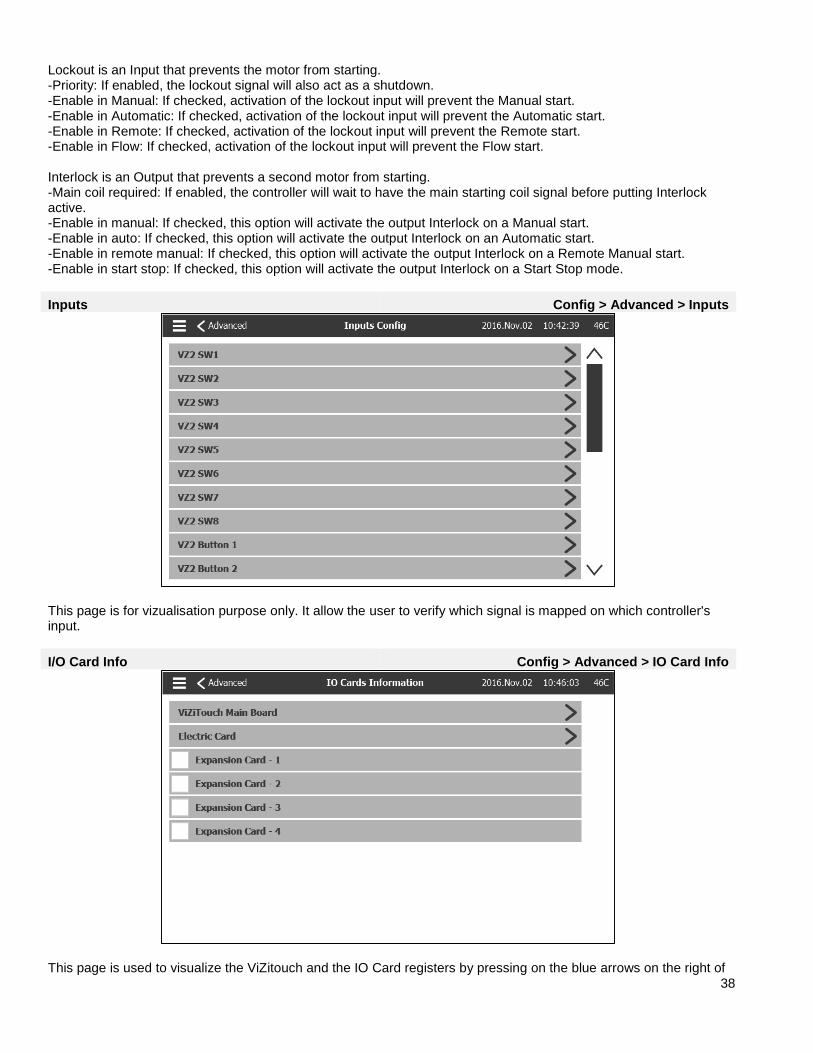
Inputs Config > Advanced > Inputs
This page is for vizualisation purpose only. It allow the user to verify which signal is mapped on which controller's input.
I/O Card Info Config > Advanced > IO Card Info
This page is used to visualize the ViZitouch and the IO Card registers by pressing on the blue arrows on the right of

39
the screen. Expansion Cards can also be installed via this page.
Network Config > Advanced > Network
This page displays the IP address, the Subnet Mask, the Default Gateway and the DNS1-2-3 of the controller. All those parameter can be changed manually by checking the box on the upper left corner. To apply the change, press on the blue arrow in the bottom right corner.
Reboot ViZiTouch Config > Advanced > Reboot ViZitouch If this button is pressed, the ViZiTouch will reboot. Any change will be saved.
40
History History (Menu) History
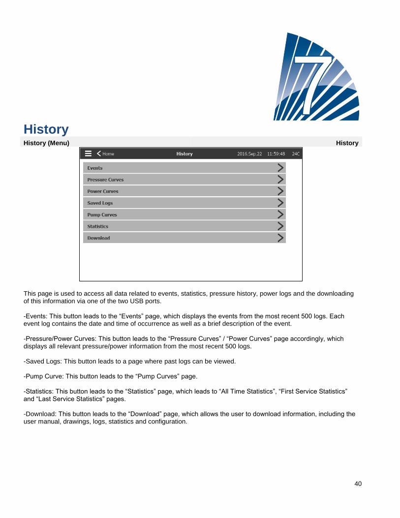
This page is used to access all data related to events, statistics, pressure history, power logs and the downloading of this information via one of the two USB ports. -Events: This button leads to the “Events” page, which displays the events from the most recent 500 logs. Each event log contains the date and time of occurrence as well as a brief description of the event. -Pressure/Power Curves: This button leads to the “Pressure Curves” / “Power Curves” page accordingly, which displays all relevant pressure/power information from the most recent 500 logs. -Saved Logs: This button leads to a page where past logs can be viewed. -Pump Curve: This button leads to the “Pump Curves” page. -Statistics: This button leads to the “Statistics” page, which leads to “All Time Statistics”, “First Service Statistics” and “Last Service Statistics” pages. -Download: This button leads to the “Download” page, which allows the user to download information, including the user manual, drawings, logs, statistics and configuration.

41
Events Page History > Events
The Events Page shows the events from the last 500 logs which occurred in chronological order. The first column is the date, the second one is the time of occurrence and the third column is the “Event message”. To obtain a log that is older than thoses events, visit the “Saved Logs”.
Pressure Curves History > Pressure Curves
On this page, a graphic of the “System Pressure”, the “Cut-in”, the “Cut-Out”, the main pump “Engine Run” and the “Jockey Pump Run” through time can be viewed. By pressing on the screen, the caption will disappear or will be displayed. The time scale can be changed by pressing the time span desired on top of the screen (from 1 minute to 2 weeks). The blue arrows on both sides of the graphic are used to navigate through time. The blue button in the bottom left corner leads to the table used to generate this graph.

42
This table allows viewing of the exact values used to generate the Pressure Curves with the precise time. Pressing the blue button on the top left corner will return to the graph page.
Power Curves History > Power Curves
On this page, a graphic of the 3 line voltages, the 3 line currents and the motor running through time can be viewed. By pressing on the screen, the caption will disappear or will be displayed. The time scale can be changed by pressing the time span desired on top of the screen (from 1 minute to 2 weeks). The blue arrows on both sides of the graphic are used to navigate through time. The blue button in the bottom left corner leads to the table used to generate this graph.

43
This table allows viewing of the exact values used to generate the Power Curves with the precise time. Press the blue button on the top left corner to return to the graph page.
Saved Logs History > Saved Logs
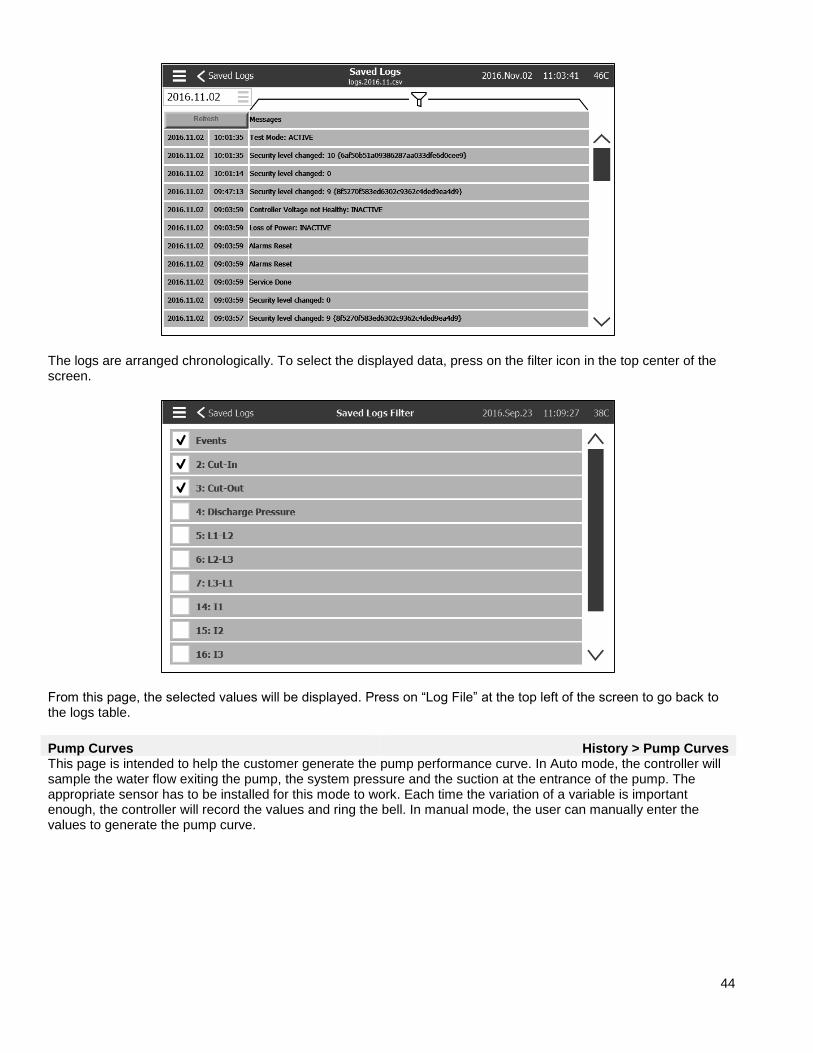
This page is used to access all past log files. Each log file is a CSV file containing the time, the date, the Cut-in, the Cut-out, the system pressure, the 3 line voltages and currents, the engine run signal, the jockey pump run signal and the log event message. Each file can contain up to 1 MB of data. The month and year are shown in the title. Each time a CSV file is full, a new one is created with an incremented number in the title. Press on the file to consult this content.
44
The logs are arranged chronologically. To select the displayed data, press on the filter icon in the top center of the screen.
From this page, the selected values will be displayed. Press on “Log File” at the top left of the screen to go back to the logs table.
Pump Curves History > Pump Curves This page is intended to help the customer generate the pump performance curve. In Auto mode, the controller will sample the water flow exiting the pump, the system pressure and the suction at the entrance of the pump. The appropriate sensor has to be installed for this mode to work. Each time the variation of a variable is important enough, the controller will record the values and ring the bell. In manual mode, the user can manually enter the values to generate the pump curve.

45
Statistic History > Statistics
This page leads to 3 other Statistics pages: “All Time Statistics”, “First Service Statistics” and “Last Service Statistics”.
All Time Statistics History > Statistics > All Time Statistics
The “All Time Statistics” contains two parameters: - Since: The date the controller has been powered for the first time. - On Time: The amount of time the controller has been On for.

46
First Service Statistics History > Statistics > First Service Statistics
This page allows the user to view the “First Setup Statistics”. The parameters are: From: - Since: Date of the first setup - On Time: Time the controller spent On, in DAYS-HOURS:MINUTES-SECONDS Motor: - On Time: Time the motor spent On, in DAYS-HOURS:MINUTES-SECONDS - Start Count: Number of times the motor has started - Last Started On: Last time the motor started Pressure: - Minimum: Smallest pressure value - Minimum Occurred On: Date the smallest value happened - Maximum: Biggest pressure value - Maximum Occurred On: Date the biggest value happened - Average: Average pressure since first startup Temperature - Minimum: Smallest temperature value - Minimum Occurred On: Date the smallest value happened - Maximum: Biggest temperature value - Maximum Occurred On: Date the biggest value happened - Average: Average temperature since first startup Jockey Pump Running - On Time: Time the Jockey Pump spent On, in DAYS-HOURS:MINUTES-SECONDS - Start Count: Number of times the Jockey Pump has started - Last Started On: Last time the Jockey Pump started

47
Last Service Statistics History > Statistics > Last Service Statistics
This page allows the user to view the “Last Setup Statistics”. The parameters are the same as the ones from the “First Setup Statistics” page but from the “Last Service”.
Download History > Download This page is used to download Statistics, PCB information, name plate information, logs, the manual, the factory settings and the current settings. A USB key needs to be inserted in the USB slot prior to entering this page in order to download.
48
Service Service
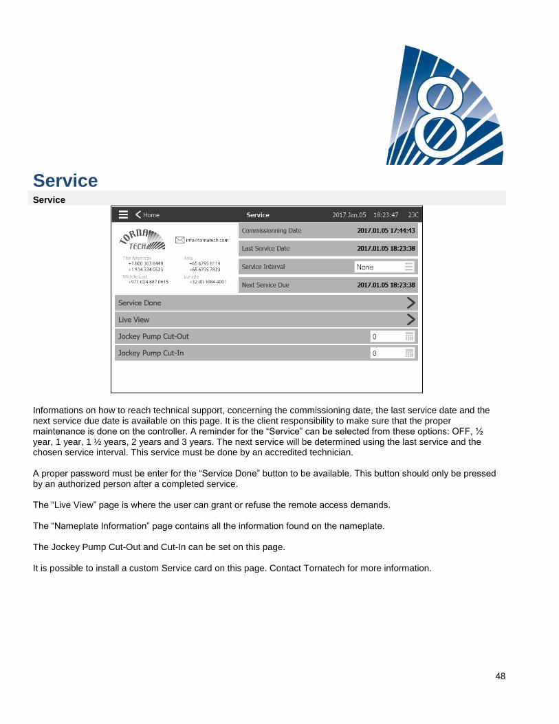
Informations on how to reach technical support, concerning the commissioning date, the last service date and the next service due date is available on this page. It is the client responsibility to make sure that the proper maintenance is done on the controller. A reminder for the “Service” can be selected from these options: OFF, ½ year, 1 year, 1 ½ years, 2 years and 3 years. The next service will be determined using the last service and the chosen service interval. This service must be done by an accredited technician. A proper password must be enter for the “Service Done” button to be available. This button should only be pressed by an authorized person after a completed service. The “Live View” page is where the user can grant or refuse the remote access demands. The “Nameplate Information” page contains all the information found on the nameplate. The Jockey Pump Cut-Out and Cut-In can be set on this page. It is possible to install a custom Service card on this page. Contact Tornatech for more information.
49
Download Manuals Pressing on the question mark will redirect to the download page. A pdf version of the manual can be downloaded on an USB device.

50
Language The language displayed on the ViZiTouch can be selected on this page.
51
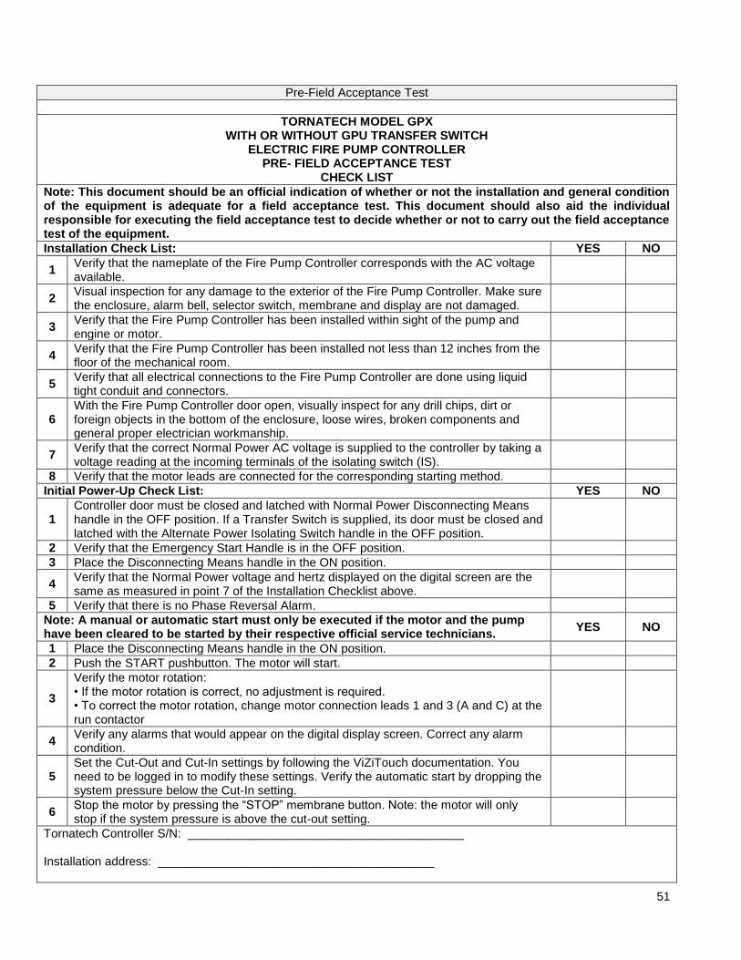
Pre-Field Acceptance Test
TORNATECH MODEL GPX WITH OR WITHOUT GPU TRANSFER SWITCH
ELECTRIC FIRE PUMP CONTROLLER PRE- FIELD ACCEPTANCE TEST
CHECK LIST
Note: This document should be an official indication of whether or not the installation and general condition of the equipment is adequate for a field acceptance test. This document should also aid the individual responsible for executing the field acceptance test to decide whether or not to carry out the field acceptance test of the equipment.
Installation Check List: YES NO
1 Verify that the nameplate of the Fire Pump Controller corresponds with the AC voltage available.
2 Visual inspection for any damage to the exterior of the Fire Pump Controller. Make sure the enclosure, alarm bell, selector switch, membrane and display are not damaged.
3 Verify that the Fire Pump Controller has been installed within sight of the pump and engine or motor.
4 Verify that the Fire Pump Controller has been installed not less than 12 inches from the floor of the mechanical room.
5 Verify that all electrical connections to the Fire Pump Controller are done using liquid tight conduit and connectors.
6 With the Fire Pump Controller door open, visually inspect for any drill chips, dirt or foreign objects in the bottom of the enclosure, loose wires, broken components and general proper electrician workmanship.
7 Verify that the correct Normal Power AC voltage is supplied to the controller by taking a voltage reading at the incoming terminals of the isolating switch (IS).
8 Verify that the motor leads are connected for the corresponding starting method.
Initial Power-Up Check List: YES NO
1 Controller door must be closed and latched with Normal Power Disconnecting Means handle in the OFF position. If a Transfer Switch is supplied, its door must be closed and latched with the Alternate Power Isolating Switch handle in the OFF position.
2 Verify that the Emergency Start Handle is in the OFF position.
3 Place the Disconnecting Means handle in the ON position.
4 Verify that the Normal Power voltage and hertz displayed on the digital screen are the same as measured in point 7 of the Installation Checklist above.
5 Verify that there is no Phase Reversal Alarm.
Note: A manual or automatic start must only be executed if the motor and the pump have been cleared to be started by their respective official service technicians.
YES NO
1 Place the Disconnecting Means handle in the ON position.
2 Push the START pushbutton. The motor will start.
3
Verify the motor rotation: • If the motor rotation is correct, no adjustment is required. • To correct the motor rotation, change motor connection leads 1 and 3 (A and C) at the run contactor
4 Verify any alarms that would appear on the digital display screen. Correct any alarm condition.
5 Set the Cut-Out and Cut-In settings by following the ViZiTouch documentation. You need to be logged in to modify these settings. Verify the automatic start by dropping the system pressure below the Cut-In setting.
6 Stop the motor by pressing the “STOP” membrane button. Note: the motor will only stop if the system pressure is above the cut-out setting.
Tornatech Controller S/N: _________________________________________ Installation address: _________________________________________
52
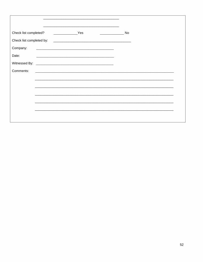
_________________________________________ _________________________________________ Check list completed? _____________Yes _____________ No Check list completed by: __________________________________________ Company: __________________________________________ Date: __________________________________________ Witnessed By: __________________________________________ Comments: ___________________________________________________________________________ ___________________________________________________________________________ ___________________________________________________________________________ ___________________________________________________________________________ ___________________________________________________________________________ ___________________________________________________________________________
53
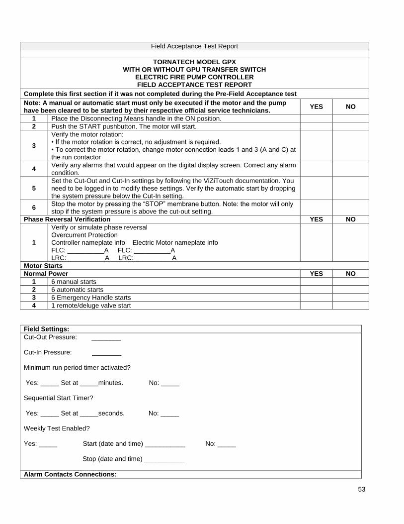
Field Acceptance Test Report
TORNATECH MODEL GPX WITH OR WITHOUT GPU TRANSFER SWITCH
ELECTRIC FIRE PUMP CONTROLLER FIELD ACCEPTANCE TEST REPORT
Complete this first section if it was not completed during the Pre-Field Acceptance test
Note: A manual or automatic start must only be executed if the motor and the pump have been cleared to be started by their respective official service technicians.
YES NO
1 Place the Disconnecting Means handle in the ON position.
2 Push the START pushbutton. The motor will start.
3
Verify the motor rotation: • If the motor rotation is correct, no adjustment is required. • To correct the motor rotation, change motor connection leads 1 and 3 (A and C) at the run contactor
4 Verify any alarms that would appear on the digital display screen. Correct any alarm condition.
5 Set the Cut-Out and Cut-In settings by following the ViZiTouch documentation. You need to be logged in to modify these settings. Verify the automatic start by dropping the system pressure below the Cut-In setting.
6 Stop the motor by pressing the “STOP” membrane button. Note: the motor will only stop if the system pressure is above the cut-out setting.
Phase Reversal Verification YES NO
1
Verify or simulate phase reversal Overcurrent Protection Controller nameplate info Electric Motor nameplate info FLC: __________A FLC: __________A LRC: __________A LRC: __________A
Motor Starts
Normal Power YES NO
1 6 manual starts
2 6 automatic starts
3 6 Emergency Handle starts
4 1 remote/deluge valve start
Field Settings:
Cut-Out Pressure: ________ Cut-In Pressure: ________ Minimum run period timer activated? Yes: _____ Set at _____minutes. No: _____ Sequential Start Timer? Yes: _____ Set at _____seconds. No: _____ Weekly Test Enabled? Yes: _____ Start (date and time) ___________ No: _____ Stop (date and time) ___________
Alarm Contacts Connections:

54
Fire Pump Controller
Motor Run connected? _____Yes _____ No Power Available connected? _____Yes _____ No Phase Reversal connected? _____Yes _____ No Other contacts supplied and connected? _____Yes _____ No
Tornatech Controller S/N: _________________________________________ Installation address: _________________________________________ _________________________________________ Field Acceptance Test completed? _____Yes _____ No Field Acceptance completed by: __________________________________________ Company: __________________________________________ Date: __________________________________________ Witnessed By: __________________________________________ Company: __________________________________________ The undersigned witness has been made aware of the NFPA20 article 14.4 Periodic Inspection, Testing and Maintenance which stipulates that “Fire pumps shall be inspected tested and maintained in accordance with NFPA25 – Standard for the Inspection, Testing and Maintenance of Water Based Fire Protection Systems” Comments: _____________________________________________________________________________ _____________________________________________________________________________ _____________________________________________________________________________ _____________________________________________________________________________ _____________________________________________________________________________

55
Related Documents


