Manufacturer reserves the right to discontinue, or change at any time, specifications or designs without notice and without incurring obligations. © 2021 Carrier. All rights reserved. Edition Date: 06/21 Form No: 40VMW-8SI A Carrier Company Printed in U.S.A. Replaces: 40VMW-7SI 1 Installation and Maintenance Instructions CONTENTS Page SAFETY CONSIDERATIONS . . . . . . . . . . . . . . . . . . . 1 GENERAL . . . . . . . . . . . . . . . . . . . . . . . . . . . . . . . . . . . 2 INSTALLATION . . . . . . . . . . . . . . . . . . . . . . . . . . . . . . . 7 Step 1 — Unpack and Inspect Units . . . . . . . . . . . . 7 Step 2 — Position the Unit . . . . . . . . . . . . . . . . . . . . 7 Step 3 — Mount the Unit . . . . . . . . . . . . . . . . . . . . . . 7 Step 4 — Connect Piping . . . . . . . . . . . . . . . . . . . . . . 8 Step 5 — Complete Electrical Connections . . . . . . 9 Step 6 — Position and Connect Controller . . . . . 11 ACB (Auxiliary Control Board) Interface . . . . . . . 15 START-UP . . . . . . . . . . . . . . . . . . . . . . . . . . . . . . . . 15 Pre-Start Check . . . . . . . . . . . . . . . . . . . . . . . . . . . . . 15 System Operation Check . . . . . . . . . . . . . . . . . . . . 15 MAINTENANCE. . . . . . . . . . . . . . . . . . . . . . . . . . . . . . 15 INDOOR UNIT ADDRESSING. . . . . . . . . . . . . . . . . 15 Wireless Remote Controller (40VM900001) . . . . . 15 Non-Programmable Controller (40VM900002). . . 16 Programmable Controller (40VM900003) . . . . . . . 16 TROUBLESHOOTING . . . . . . . . . . . . . . . . . . . . . . 18 Replacement Parts . . . . . . . . . . . . . . . . . . . . . . . . . . 19 APPENDIX A — DIP SWITCH SETTINGS . . . . . . . . . 20 SAFETY CONSIDERATIONS Improper installation, adjustment, alteration, service, maintenance, or use can cause explosion, fire, electrical shock, or other conditions that may cause death, personal injury or property damage. The qualified installer or agency must use factory-authorized kits or accessories when modifying this product. Follow all safety codes. Wear safety glasses, protective clothing, and work gloves. Use quenching cloth for brazing operations. Have fire extinguisher available. Read these instructions thoroughly and follow all warnings or cautions included in literature and attached to the unit. Consult local building codes and the current editions of the National Electrical Code (NEC) ANSI/NFPA (American National Standards Institute/National Fire Protection Association) 70. In Canada, refer to the current editions of the Canadian Electrical Code CSA (Canadian Standards Association) C22.1. Understand the signal words — DANGER, WARNING, and CAUTION. DANGER identifies the most serious hazards, which will result in severe personal injury or death. WARNING signifies hazards that could result in personal injury or death. CAUTION is used to identify unsafe practices, which would result in minor personal injury or product and property damage. Recognize safety information. This is the safety-alert symbol ( ). When this symbol is displayed on the unit and in instructions or manuals, be alert to the potential for personal injury. WARNING Electrical shock can cause personal injury and death. Shut off all power to this equipment during installation. There may be more than one disconnect switch. Tag all disconnect locations to alert others not to restore power until work is completed. WARNING When installing the equipment in a small space, provide adequate measures to avoid refrigerant concentration exceeding safety limits due to refrigerant leak. In case of refrigerant leak during installation, ventilate the space immediately. Failure to follow this procedure may lead to personal injury. WARNING DO NOT USE TORCH to remove any component. System contains oil and refrigerant under pressure. To remove a component, wear protective gloves and goggles and proceed as follows: a. Shut off electrical power to unit. b. Recover refrigerant to relieve all pressure from system using both high-pressure and low-pressure ports. c. Traces of vapor should be displaced with nitrogen and the work area should be well ventilated. Refrigerant in contact with an open flame produces toxic gases. d. Cut component connection tubing with tubing cutter and remove component from unit. Use a pan to catch any oil that may come out of the lines and as a gage for how much oil to add to the system. e. Carefully unsweat remaining tubing stubs when necessary. Oil can ignite when exposed to torch flame. Failure to follow these procedures may result in personal injury or death. 40VMW005-030 High Wall Indoor Unit for Variable Refrigerant Flow (VRF) Systems

Welcome message from author
This document is posted to help you gain knowledge. Please leave a comment to let me know what you think about it! Share it to your friends and learn new things together.
Transcript
Manufacturer reserves the right to discontinue, or change at any time, specifications or designs without notice and without incurring obligations.
© 2021 Carrier. All rights reserved. Edition Date: 06/21 Form No: 40VMW-8SIA Carrier Company Printed in U.S.A. Replaces: 40VMW-7SI
1
Installation and Maintenance InstructionsCONTENTS
PageSAFETY CONSIDERATIONS . . . . . . . . . . . . . . . . . . . 1GENERAL . . . . . . . . . . . . . . . . . . . . . . . . . . . . . . . . . . . 2INSTALLATION . . . . . . . . . . . . . . . . . . . . . . . . . . . . . . . 7Step 1 — Unpack and Inspect Units . . . . . . . . . . . . 7Step 2 — Position the Unit . . . . . . . . . . . . . . . . . . . . 7Step 3 — Mount the Unit . . . . . . . . . . . . . . . . . . . . . . 7Step 4 — Connect Piping . . . . . . . . . . . . . . . . . . . . . . 8Step 5 — Complete Electrical Connections . . . . . . 9Step 6 — Position and Connect Controller . . . . . 11ACB (Auxiliary Control Board) Interface . . . . . . . 15START-UP . . . . . . . . . . . . . . . . . . . . . . . . . . . . . . . . 15Pre-Start Check . . . . . . . . . . . . . . . . . . . . . . . . . . . . . 15System Operation Check . . . . . . . . . . . . . . . . . . . . 15MAINTENANCE. . . . . . . . . . . . . . . . . . . . . . . . . . . . . . 15INDOOR UNIT ADDRESSING. . . . . . . . . . . . . . . . . 15Wireless Remote Controller (40VM900001) . . . . . 15Non-Programmable Controller (40VM900002). . . 16Programmable Controller (40VM900003). . . . . . . 16TROUBLESHOOTING . . . . . . . . . . . . . . . . . . . . . . 18Replacement Parts . . . . . . . . . . . . . . . . . . . . . . . . . . 19APPENDIX A — DIP SWITCH SETTINGS . . . . . . . . . 20
SAFETY CONSIDERATIONSImproper installation, adjustment, alteration, service,maintenance, or use can cause explosion, fire, electrical shock,or other conditions that may cause death, personal injury orproperty damage. The qualified installer or agency must usefactory-authorized kits or accessories when modifying thisproduct.Follow all safety codes. Wear safety glasses, protectiveclothing, and work gloves. Use quenching cloth for brazingoperations. Have fire extinguisher available. Read theseinstructions thoroughly and follow all warnings or cautionsincluded in literature and attached to the unit. Consult localbuilding codes and the current editions of the NationalElectrical Code (NEC) ANSI/NFPA (American NationalStandards Institute/National Fire Protection Association) 70. InCanada, refer to the current editions of the Canadian ElectricalCode CSA (Canadian Standards Association) C22.1.Understand the signal words — DANGER, WARNING, andCAUTION. DANGER identifies the most serious hazards,which will result in severe personal injury or death.WARNING signifies hazards that could result in personal injuryor death. CAUTION is used to identify unsafe practices, whichwould result in minor personal injury or product and propertydamage.Recognize safety information. This is the safety-alertsymbol ( ). When this symbol is displayed on the unit and ininstructions or manuals, be alert to the potential for personalinjury.
WARNINGElectrical shock can cause personal injury and death. Shutoff all power to this equipment during installation. Theremay be more than one disconnect switch. Tag alldisconnect locations to alert others not to restore poweruntil work is completed.
WARNINGWhen installing the equipment in a small space, provideadequate measures to avoid refrigerant concentrationexceeding safety limits due to refrigerant leak. In case ofrefrigerant leak during installation, ventilate the spaceimmediately. Failure to follow this procedure may lead topersonal injury.
WARNINGDO NOT USE TORCH to remove any component. Systemcontains oil and refrigerant under pressure. To remove a component, wear protective gloves andgoggles and proceed as follows:a. Shut off electrical power to unit.b. Recover refrigerant to relieve all pressure from
system using both high-pressure and low-pressureports.
c. Traces of vapor should be displaced with nitrogenand the work area should be well ventilated.Refrigerant in contact with an open flame producestoxic gases.
d. Cut component connection tubing with tubing cutterand remove component from unit. Use a pan to catchany oil that may come out of the lines and as a gagefor how much oil to add to the system.
e. Carefully unsweat remaining tubing stubs whennecessary. Oil can ignite when exposed to torchflame.
Failure to follow these procedures may result in personalinjury or death.
40VMW005-030High Wall Indoor Unit for
Variable Refrigerant Flow (VRF) Systems
2
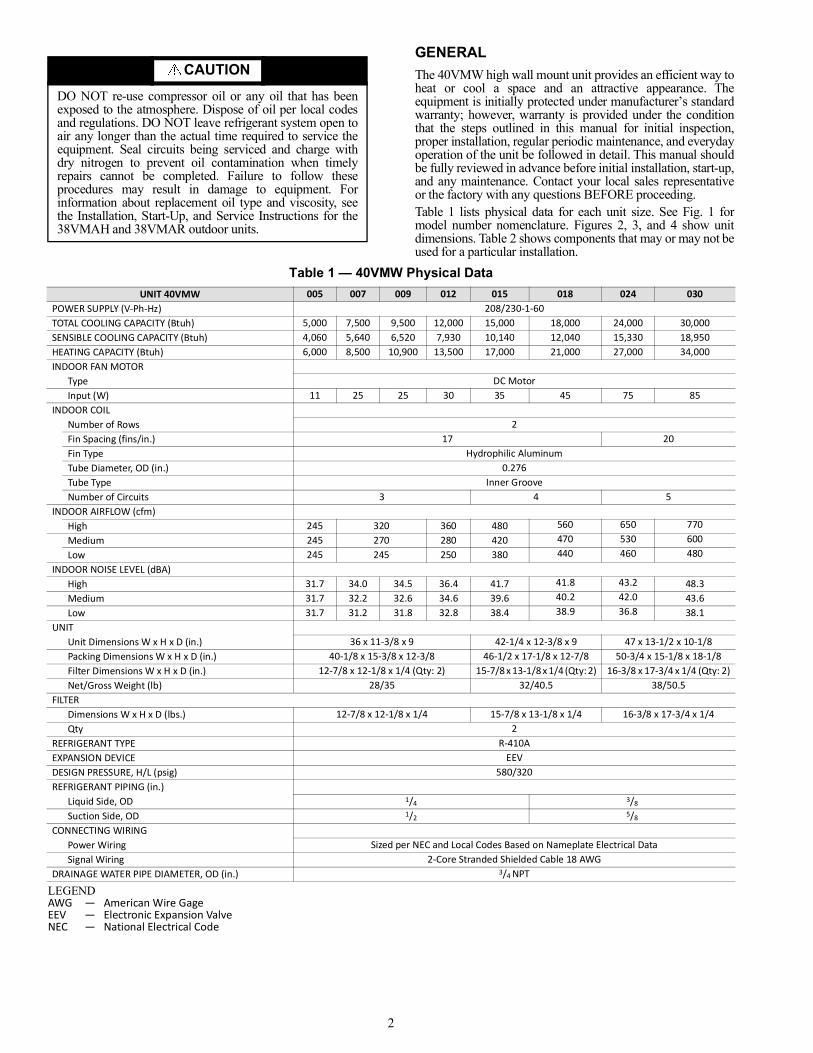
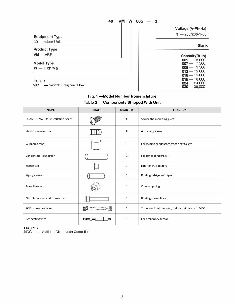
GENERALThe 40VMW high wall mount unit provides an efficient way toheat or cool a space and an attractive appearance. Theequipment is initially protected under manufacturer’s standardwarranty; however, warranty is provided under the conditionthat the steps outlined in this manual for initial inspection,proper installation, regular periodic maintenance, and everydayoperation of the unit be followed in detail. This manual shouldbe fully reviewed in advance before initial installation, start-up,and any maintenance. Contact your local sales representativeor the factory with any questions BEFORE proceeding.Table 1 lists physical data for each unit size. See Fig. 1 formodel number nomenclature. Figures 2, 3, and 4 show unitdimensions. Table 2 shows components that may or may not beused for a particular installation.
Table 1 — 40VMW Physical Data
CAUTIONDO NOT re-use compressor oil or any oil that has beenexposed to the atmosphere. Dispose of oil per local codesand regulations. DO NOT leave refrigerant system open toair any longer than the actual time required to service theequipment. Seal circuits being serviced and charge withdry nitrogen to prevent oil contamination when timelyrepairs cannot be completed. Failure to follow theseprocedures may result in damage to equipment. Forinformation about replacement oil type and viscosity, seethe Installation, Start-Up, and Service Instructions for the38VMAH and 38VMAR outdoor units.
UNIT 40VMW 005 007 009 012 015 018 024 030POWER SUPPLY (V-Ph-Hz) 208/230-1-60TOTAL COOLING CAPACITY (Btuh) 5,000 7,500 9,500 12,000 15,000 18,000 24,000 30,000SENSIBLE COOLING CAPACITY (Btuh) 4,060 5,640 6,520 7,930 10,140 12,040 15,330 18,950HEATING CAPACITY (Btuh) 6,000 8,500 10,900 13,500 17,000 21,000 27,000 34,000INDOOR FAN MOTOR
Type DC MotorInput (W) 11 25 25 30 35 45 75 85
INDOOR COILNumber of Rows 2Fin Spacing (fins/in.) 17 20Fin Type Hydrophilic AluminumTube Diameter, OD (in.) 0.276Tube Type Inner GrooveNumber of Circuits 3 4 5
INDOOR AIRFLOW (cfm)High 245 320 360 480 560 650 770Medium 245 270 280 420 470 530 600Low 245 245 250 380 440 460 480
INDOOR NOISE LEVEL (dBA)High 31.7 34.0 34.5 36.4 41.7 41.8 43.2 48.3Medium 31.7 32.2 32.6 34.6 39.6 40.2 42.0 43.6Low 31.7 31.2 31.8 32.8 38.4 38.9 36.8 38.1
UNITUnit Dimensions W x H x D (in.) 36 x 11-3/8 x 9 42-1/4 x 12-3/8 x 9 47 x 13-1/2 x 10-1/8Packing Dimensions W x H x D (in.) 40-1/8 x 15-3/8 x 12-3/8 46-1/2 x 17-1/8 x 12-7/8 50-3/4 x 15-1/8 x 18-1/8Filter Dimensions W x H x D (in.) 12-7/8 x 12-1/8 x 1/4 (Qty: 2) 15-7/8 x 13-1/8 x 1/4 (Qty: 2) 16-3/8 x 17-3/4 x 1/4 (Qty: 2)Net/Gross Weight (lb) 28/35 32/40.5 38/50.5
FILTERDimensions W x H x D (lbs.) 12-7/8 x 12-1/8 x 1/4 15-7/8 x 13-1/8 x 1/4 16-3/8 x 17-3/4 x 1/4Qty 2
REFRIGERANT TYPE R-410AEXPANSION DEVICE EEVDESIGN PRESSURE, H/L (psig) 580/320REFRIGERANT PIPING (in.)
Liquid Side, OD 1/4 3/8
Suction Side, OD 1/2 5/8
CONNECTING WIRINGPower Wiring Sized per NEC and Local Codes Based on Nameplate Electrical DataSignal Wiring 2-Core Stranded Shielded Cable 18 AWG
DRAINAGE WATER PIPE DIAMETER, OD (in.) 3/4 NPT
LEGENDAWG — American Wire GageEEV — Electronic Expansion ValveNEC — National Electrical Code
3
Fig. 1 —Model Number NomenclatureTable 2 — Components Shipped With Unit
NAME SHAPE QUANTITY FUNCTION
Screw ST3.9x25 for installation board 8 Secure the mounting plate
Plastic screw anchor 8 Anchoring screw
Wrapping tape 1 For routing condensate from right to left
Condensate connection 1 For connecting drain
Sleeve cap 1 Exterior wall opening
Piping sleeve 1 Routing refrigerant pipes
Brass flare nut 1 Connect piping
Flexible conduit and connectors 1 Routing power lines
PQE connection wire 2 To connect outdoor unit, indoor unit, and sub MDC
Connecting wire 1 For occupancy sensor
LEGENDMDC — Multiport Distribution Controller
40 VM W 005 --- 3
Product Type
Equipment Type 40 — Indoor Unit
VM — VRF
Blank
Voltage (V-Ph-Hz) 3 — 208/230-1-60
Model Type W — High Wall
Capacity (Btuh)005 — 5,000007 — 7,500009 — 9,500012 — 12,000015 — 15,000018 — 18,000024 — 24,000030 — 30,000
LEGENDVRF — Variable Refrigerant Flow
4
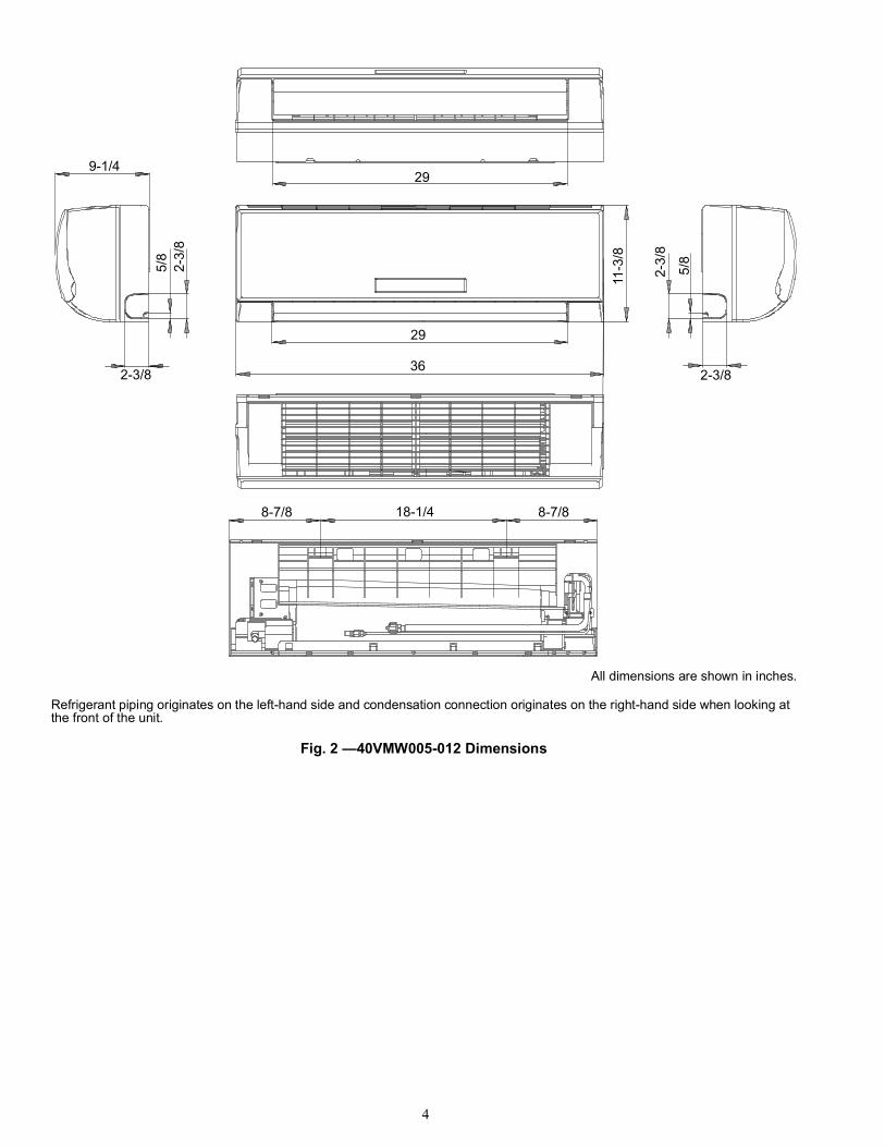
Fig. 2 —40VMW005-012 Dimensions
9-1/45/
82-
3/8
2-3/8
29
29
36
8-7/8 18-1/4 8-7/8
11-3
/8
2-3/
8
5/8
2-3/8
All dimensions are shown in inches.
Refrigerant piping originates on the left-hand side and condensation connection originates on the right-hand side when looking at the front of the unit.
5
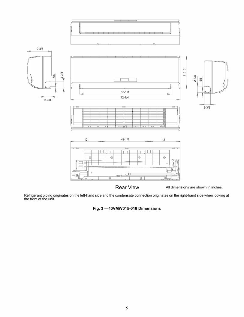
Fig. 3 —40VMW015-018 Dimensions
Rear View
9-3/8
5/8
2-3/
8
2-3/
8
5/8
2-3/8
2-3/8
35-1/8
42-1/4
12 1242-1/4
All dimensions are shown in inches.
Refrigerant piping originates on the left-hand side and the condensate connection originates on the right-hand side when looking at the front of the unit.
6
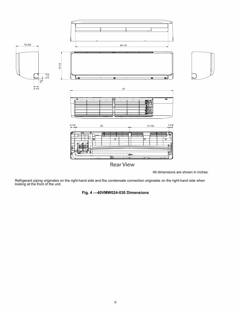
Fig. 4 —40VMW024-030 Dimensions
10-3/8
13-1
/2
42-1/2
47
2-1/4 25 17-7/8 1-7/8
2-1/4
1/2
2-1/
2
Rear ViewAll dimensions are shown in inches.
Refrigerant piping originates on the right-hand side and the condensate connection originates on the right-hand side when looking at the front of the unit.
7
INSTALLATIONStep 1 — Unpack and Inspect Units — Units are packaged for shipment to avoid damage during normal transit and handling. It is the receiving party’s responsibility to inspect the equipment upon arrival. Any obvious damage to the carton and/or its contents should be reported on the bill of lading and a claim should be filed with the transportation company and the factory. Unit should always be stored in a dry place, and in the proper orientation as marked on the carton.
After determining the condition of carton exterior, carefullyremove each unit from the carton and inspect for hiddendamage. Check to make sure that items such as thermostats andcontrollers are accounted for whether packaged separately orshipped at a later date. Any hidden damage should be recorded,a claim should be filed with the transportation company, andthe factory should be notified. In the event a claim for shippingdamage is filed, the unit, shipping carton, and all packing mustbe retained for physical inspection by the transportationcompany. All units should be stored in the factory shippingcarton with internal packaging in place until installation.PROTECTING UNITS FROM DAMAGE — Do not apply force or pressure to coil, piping, or drain stub-outsduring handling. All units should be handled by the chassis oras close as possible to the unit mounting point locations. The unit must always be properly supported. Temporarysupports used during installation or service must be adequate tohold the unit securely. To maintain warranty, protect unitsagainst hostile environments (such as rain, snow or extremetemperature), theft, vandalism, and debris on jobsite.Equipment covered in this manual is not suitable for outdoorinstallations. Do not allow foreign material to fall into drainpan. Prevent dust and debris from being deposited on motor,fan wheels, and coils. Failure to do so may have seriousadverse effects on unit operation, and in the case of motor andblower assembly, may result in immediate or premature failure.Failure of any unit caused by deposits of foreign material onthe motor or blower wheels will not be covered by themanufacturer’s warranty. Some units and/or job conditionsmay require some form of temporary covering duringconstruction.PREPARING JOBSITE FOR UNIT INSTALLATION — To save time and to reduce the possibility of costly errors, setup a complete sample installation in a typical room at jobsite.Check all critical dimensions such as pipe, wire, and ductconnections requirements. Refer to job drawings and product
dimension drawings as required. Instruct all trades in their partsof the installation. Units must be installed in compliance withall applicable local code requirements.IDENTIFYING AND PREPARING UNITS — Be sure power requirements match available power source. Refer to unit nameplate and wiring diagram. In addition:• Check all tags on unit to determine if shipping screws are
to be removed. Remove screws as directed.• Rotate fan wheel by hand to ensure that fan is
unrestricted and can rotate freely. Check for shippingdamage and fan obstructions. Adjust blower motor asrequired.
Step 2 — Position the Unit
Select the unit position with the following points in mind:• The unit should be installed on wall studs that are strong
enough to support the total weight of the unit, refrigerantpiping, and condensate. The wall should be flat with nohumps or indentions.
• The unit should be mounted eight feet or more from thefloor, and if possible, centrally located on the wall fromboth ends.
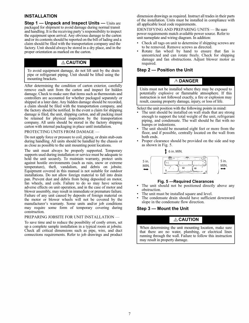
• Proper clearance should be provided on the side and topas shown in Fig. 5.
Fig. 5 —Required Clearances• The unit should not be positioned directly above any
obstruction.• The unit must be installed square and level.• The condensate drain should have sufficient downward
slope in the condensate flow direction.
Step 3 — Mount the Unit
CAUTIONTo avoid equipment damage, do not lift unit by the drainpipe or refrigerant piping. Unit should be lifted using themounting brackets. DANGER
Units must not be installed where they may be exposed topotentially explosive or flammable atmosphere. If thisinstruction is not followed exactly, a fire or explosion mayresult, causing property damage, injury, or loss of life.
CAUTIONWhen determining the unit mounting location, make surethat there are no water, plumbing, or electrical linesrunning through the wall. Failure to follow this instructionmay result in property damage.
6 in. MIN.
5 in.MIN.
5 in.MIN.
8
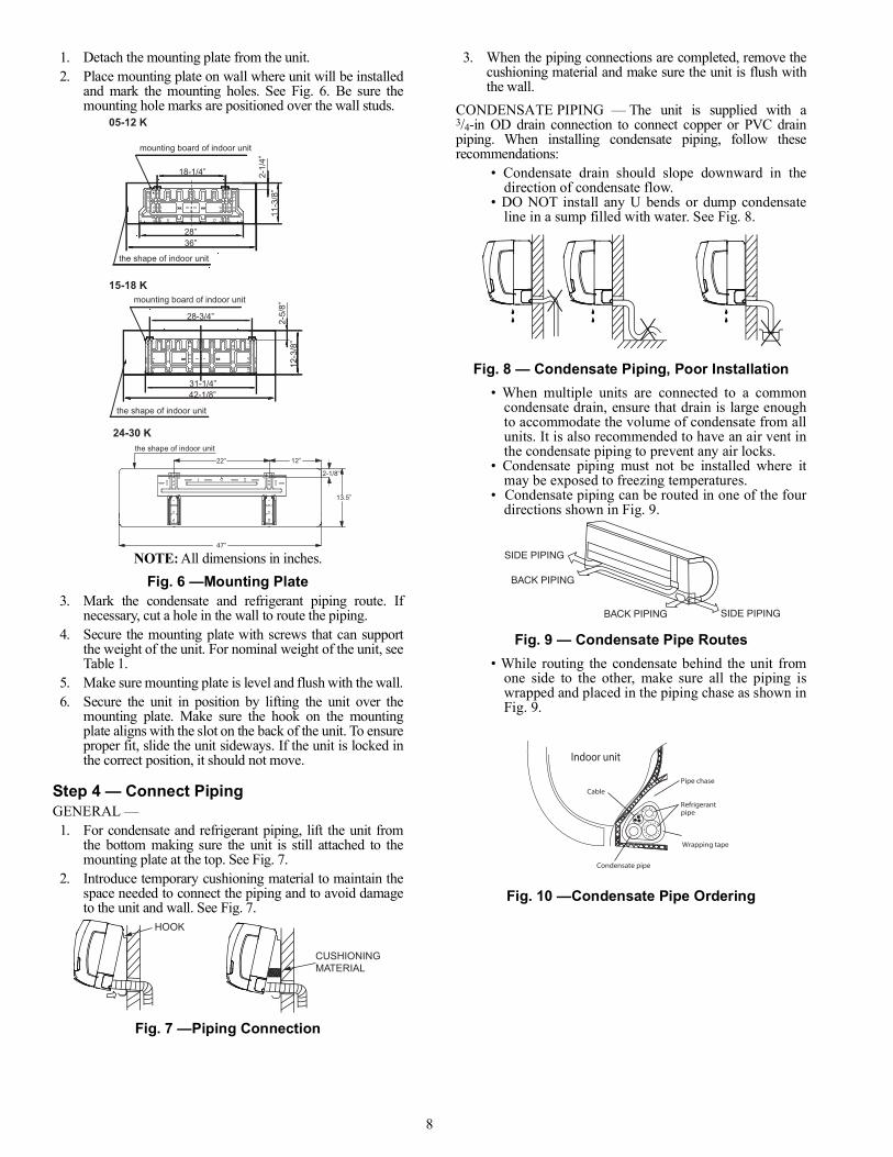
1. Detach the mounting plate from the unit.2. Place mounting plate on wall where unit will be installed
and mark the mounting holes. See Fig. 6. Be sure themounting hole marks are positioned over the wall studs.
NOTE: All dimensions in inches.Fig. 6 —Mounting Plate
3. Mark the condensate and refrigerant piping route. Ifnecessary, cut a hole in the wall to route the piping.
4. Secure the mounting plate with screws that can supportthe weight of the unit. For nominal weight of the unit, seeTable 1.
5. Make sure mounting plate is level and flush with the wall.6. Secure the unit in position by lifting the unit over the
mounting plate. Make sure the hook on the mountingplate aligns with the slot on the back of the unit. To ensureproper fit, slide the unit sideways. If the unit is locked inthe correct position, it should not move.
Step 4 — Connect PipingGENERAL — 1. For condensate and refrigerant piping, lift the unit from
the bottom making sure the unit is still attached to themounting plate at the top. See Fig. 7.
2. Introduce temporary cushioning material to maintain thespace needed to connect the piping and to avoid damageto the unit and wall. See Fig. 7.
Fig. 7 —Piping Connection
3. When the piping connections are completed, remove thecushioning material and make sure the unit is flush withthe wall.
CONDENSATE PIPING — The unit is supplied with a3/4-in OD drain connection to connect copper or PVC drainpiping. When installing condensate piping, follow theserecommendations:
• Condensate drain should slope downward in thedirection of condensate flow.
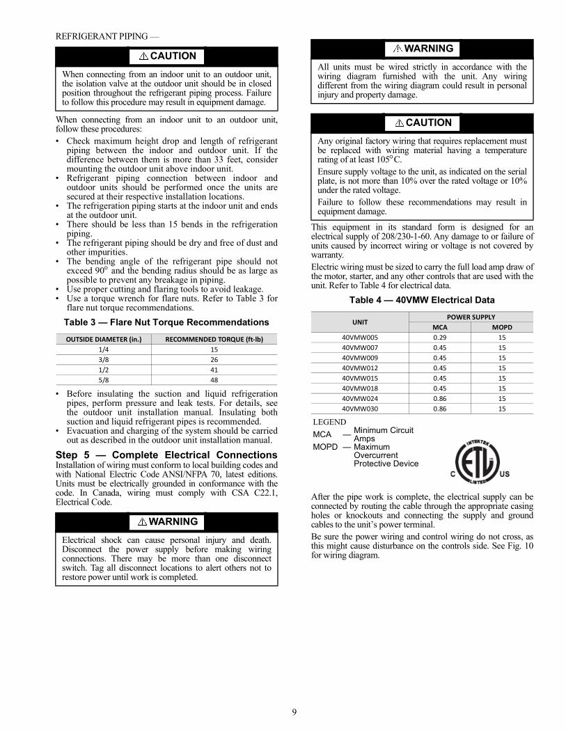
• DO NOT install any U bends or dump condensateline in a sump filled with water. See Fig. 8.
Fig. 8 — Condensate Piping, Poor Installation• When multiple units are connected to a common
condensate drain, ensure that drain is large enoughto accommodate the volume of condensate from allunits. It is also recommended to have an air vent inthe condensate piping to prevent any air locks.
• Condensate piping must not be installed where itmay be exposed to freezing temperatures.
• Condensate piping can be routed in one of the fourdirections shown in Fig. 9.
Fig. 9 — Condensate Pipe Routes• While routing the condensate behind the unit from
one side to the other, make sure all the piping iswrapped and placed in the piping chase as shown inFig. 9.
Fig. 10 —Condensate Pipe Ordering
05-12 K
15-18 K
18-1/4” 2-1/
4”11
-3/8
”
36”28”
mounting board of indoor unit
the shape of indoor unit
12-3
/8”
42-1/8”31-1/4”
28-3/4” 2-5/
8”
mounting board of indoor unit
the shape of indoor unit
24-30 K
22”
47”
2-1/8”
13.5”
12”
the shape of indoor unit
CUSHIONINGMATERIAL
HOOK
SIDE PIPING
BACK PIPING
BACK PIPING SIDE PIPING
Cable
pipeRefrigerant
Pipe chase
Wrapping tape
Indoor unit
.....
..
.
.........
.... .
.... .
..
.
. .
Condensate pipe
9
REFRIGERANT PIPING —
When connecting from an indoor unit to an outdoor unit,follow these procedures:• Check maximum height drop and length of refrigerant
piping between the indoor and outdoor unit. If thedifference between them is more than 33 feet, considermounting the outdoor unit above indoor unit.
• Refrigerant piping connection between indoor andoutdoor units should be performed once the units aresecured at their respective installation locations.
• The refrigeration piping starts at the indoor unit and endsat the outdoor unit.
• There should be less than 15 bends in the refrigerationpiping.
• The refrigerant piping should be dry and free of dust andother impurities.
• The bending angle of the refrigerant pipe should notexceed 90 and the bending radius should be as large aspossible to prevent any breakage in piping.
• Use proper cutting and flaring tools to avoid leakage.• Use a torque wrench for flare nuts. Refer to Table 3 for
flare nut torque recommendations.Table 3 — Flare Nut Torque Recommendations
• Before insulating the suction and liquid refrigerationpipes, perform pressure and leak tests. For details, seethe outdoor unit installation manual. Insulating bothsuction and liquid refrigerant pipes is recommended.
• Evacuation and charging of the system should be carriedout as described in the outdoor unit installation manual.
Step 5 — Complete Electrical ConnectionsInstallation of wiring must conform to local building codes andwith National Electric Code ANSI/NFPA 70, latest editions.Units must be electrically grounded in conformance with thecode. In Canada, wiring must comply with CSA C22.1,Electrical Code.
This equipment in its standard form is designed for anelectrical supply of 208/230-1-60. Any damage to or failure ofunits caused by incorrect wiring or voltage is not covered bywarranty.Electric wiring must be sized to carry the full load amp draw ofthe motor, starter, and any other controls that are used with theunit. Refer to Table 4 for electrical data.
Table 4 — 40VMW Electrical Data
After the pipe work is complete, the electrical supply can beconnected by routing the cable through the appropriate casingholes or knockouts and connecting the supply and groundcables to the unit’s power terminal.Be sure the power wiring and control wiring do not cross, asthis might cause disturbance on the controls side. See Fig. 10for wiring diagram.
CAUTIONWhen connecting from an indoor unit to an outdoor unit,the isolation valve at the outdoor unit should be in closedposition throughout the refrigerant piping process. Failureto follow this procedure may result in equipment damage.
OUTSIDE DIAMETER (in.) RECOMMENDED TORQUE (ft-lb)1/4 153/8 261/2 415/8 48
WARNINGElectrical shock can cause personal injury and death.Disconnect the power supply before making wiringconnections. There may be more than one disconnectswitch. Tag all disconnect locations to alert others not torestore power until work is completed.
WARNINGAll units must be wired strictly in accordance with thewiring diagram furnished with the unit. Any wiringdifferent from the wiring diagram could result in personalinjury and property damage.
CAUTIONAny original factory wiring that requires replacement mustbe replaced with wiring material having a temperaturerating of at least 105C.Ensure supply voltage to the unit, as indicated on the serialplate, is not more than 10% over the rated voltage or 10%under the rated voltage.Failure to follow these recommendations may result inequipment damage.
UNITPOWER SUPPLY
MCA MOPD40VMW005 0.29 1540VMW007 0.45 1540VMW009 0.45 1540VMW012 0.45 1540VMW015 0.45 1540VMW018 0.45 1540VMW024 0.86 1540VMW030 0.86 15
LEGENDMCA — Minimum Circuit
AmpsMOPD — Maximum
OvercurrentProtective Device
10
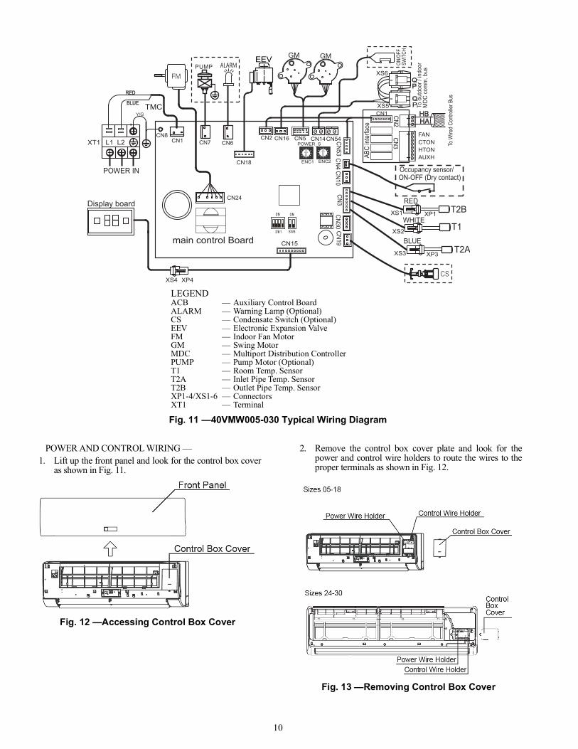
Fig. 11 —40VMW005-030 Typical Wiring Diagram
POWER AND CONTROL WIRING —1. Lift up the front panel and look for the control box cover
as shown in Fig. 11.
Fig. 12 —Accessing Control Box Cover
2. Remove the control box cover plate and look for thepower and control wire holders to route the wires to theproper terminals as shown in Fig. 12.
Fig. 13 —Removing Control Box Cover
LEGENDACB — Auxiliary Control BoardALARM — Warning Lamp (Optional)CS — Condensate Switch (Optional)EEV — Electronic Expansion ValveFM — Indoor Fan MotorGM — Swing MotorMDC — Multiport Distribution ControllerPUMP — Pump Motor (Optional)T1 — Room Temp. SensorT2A — Inlet Pipe Temp. SensorT2B — Outlet Pipe Temp. SensorXP1-4/XS1-6 — ConnectorsXT1 — Terminal
SW8
ENC1
POWER_S
CN15
XT1
RED
BLUE TMC
EEV
To W
ired
Cont
rolle
r Bus
ON/O
FFSW
ITCH
T2B
T1
T2A
Display board
main control Board
CN1 CN6CN5CN2 CN16
Y/G
GM
XS3 XP3
WHITEXS2
CN18
CN24
CN8
ENC2
CN7 CN14CN54
CN3
GM
CN53CN4
CN10CN30
CN19
XS1 XP1
RED
HAHB
ABC
inter
face
To o
utdo
or /
indo
orM
DC c
omm
. bus
CN1
CN3CN2
AUXHHTONCTONFAN
L1 L2
XS5
XS6
BLUE
PQ
PQ
POWER IN Occupancy sensor/ON-OFF (Dry contact)
XS4 XP4
11
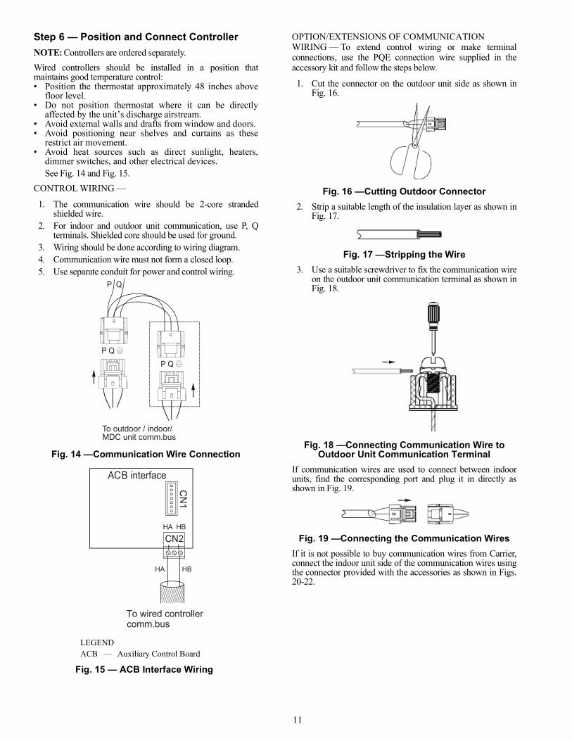
Step 6 — Position and Connect ControllerNOTE: Controllers are ordered separately.Wired controllers should be installed in a position thatmaintains good temperature control:• Position the thermostat approximately 48 inches above
floor level.• Do not position thermostat where it can be directly
affected by the unit’s discharge airstream.• Avoid external walls and drafts from window and doors.• Avoid positioning near shelves and curtains as these
restrict air movement.• Avoid heat sources such as direct sunlight, heaters,
dimmer switches, and other electrical devices.See Fig. 14 and Fig. 15.
CONTROL WIRING —
1. The communication wire should be 2-core strandedshielded wire.
2. For indoor and outdoor unit communication, use P, Qterminals. Shielded core should be used for ground.
3. Wiring should be done according to wiring diagram.4. Communication wire must not form a closed loop.5. Use separate conduit for power and control wiring.
Fig. 14 —Communication Wire Connection
OPTION/EXTENSIONS OF COMMUNICATION WIRING — To extend control wiring or make terminalconnections, use the PQE connection wire supplied in theaccessory kit and follow the steps below.
1. Cut the connector on the outdoor unit side as shown inFig. 16.
Fig. 16 —Cutting Outdoor Connector2. Strip a suitable length of the insulation layer as shown in
Fig. 17.
Fig. 17 —Stripping the Wire3. Use a suitable screwdriver to fix the communication wire
on the outdoor unit communication terminal as shown inFig. 18.
Fig. 18 —Connecting Communication Wire to Outdoor Unit Communication Terminal
If communication wires are used to connect between indoorunits, find the corresponding port and plug it in directly asshown in Fig. 19.
Fig. 19 —Connecting the Communication WiresIf it is not possible to buy communication wires from Carrier,connect the indoor unit side of the communication wires usingthe connector provided with the accessories as shown in Figs.20-22.
P Q P Q
P Q
To outdoor / indoor/ MDC unit comm.bus
Fig. 15 — ACB Interface Wiring
LEGEND ACB — Auxiliary Control Board
CN2
ACB interface
HA HB
To wired controller comm.bus
CN
1
HA HB
12
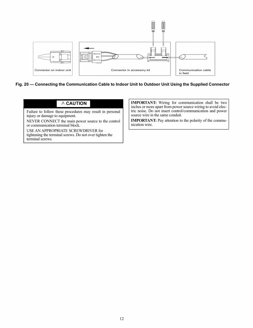
CAUTIONFailure to follow these procedures may result in personalinjury or damage to equipment.NEVER CONNECT the main power source to the controlor communication terminal block.USE AN APPROPRIATE SCREWDRIVER for tightening the terminal screws. Do not over tighten the terminal screws.
IMPORTANT: Wiring for communication shall be twoinches or more apart from power source wiring to avoid elec-tric noise. Do not insert control/communication and powersource wire in the same conduit.IMPORTANT: Pay attention to the polarity of the commu-nication wire.
Connector in accessory kitConnector on indoor unit Communication cablein field
Fig. 20 — Connecting the Communication Cable to Indoor Unit to Outdoor Unit Using the Supplied Connector
13
P Q X Y
X Y
Main MDC
MDC
outdoor unit Centralized controller
HA HB
P Q
P Q
P Q
P Q
P Q
P Q
wired controller
HA HB
To No.1indoor
To No.2indoor
To No.3indoor
To No.4indoor
To No.1indoor
To No.2indoor
To outdoor
To Sub.MDC
To outdoor
Indoor unit 1#
L1
L2
L3
L3
L3
L3
L4
L4
L5
L6
L7
L8
L9
L10
L11
Indoor unit 2#
Indoor unit 3#
Indoor unit 4#
Indoor unit 5#
Indoor unit 6#
Touch screenwired controller
Note: 24v DC Power
Note: Power from IDU
Maximum wiring lengthL1+L2 < 3937 ft. 18 AWG, 2-Core Stranded ShieldL3 < 3937 ft. 18 AWG, 2-Core Stranded ShieldL4 < 3937 ft. 18 AWG, 2-Core Stranded ShieldL5 < 3937 ft. 18 AWG, 2-Core Stranded ShieldL6+L7+L8+L9 < 820 ft. 18 AWG, 2 CoreL10+L11 < 820 ft. 18 AWG, 2 Core
HA H
BH
A HB
HA H
BH
A HB
HA H
BH
A HB
LEGENDAWG — American Wire GageIDU — Indoor UnitMDC — Multiport Distribution Controller
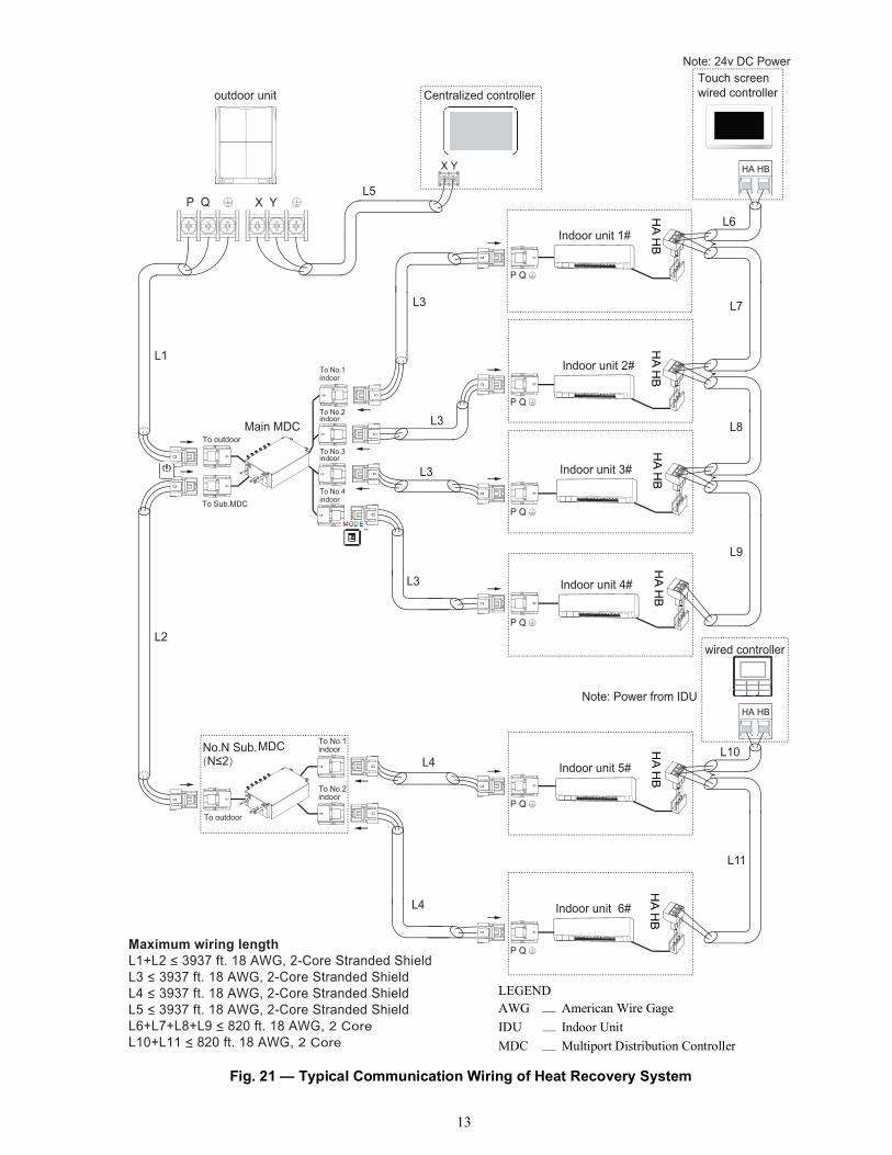
Fig. 21 — Typical Communication Wiring of Heat Recovery System
14
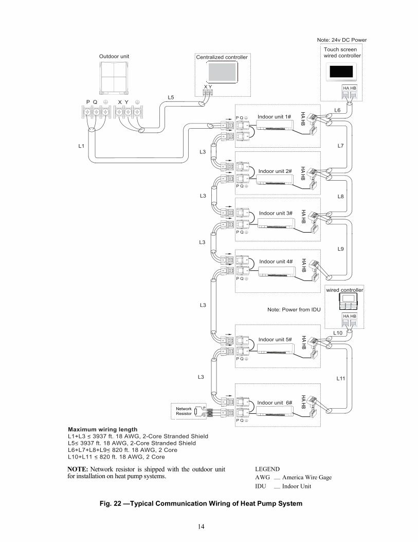
Fig. 22 —Typical Communication Wiring of Heat Pump System
P Q X Y
X Y
Centralized controller
HA HB
P Q
P Q
P Q
P Q
P Q
P Q
wired controller
HA HB
L1L3
L5
L6
L7
L8
L9
L10
L11
L3
L3
L3
L3
Outdoor unit
Indoor unit 5#
Indoor unit 6#
Indoor unit 3#
Indoor unit 4#
Indoor unit 2#
Indoor unit 1#
P
Q
Note: Power from IDU
Maximum wiring lengthL1+L3 < 3937 ft. 18 AWG, 2-Core Stranded ShieldL5< 3937 ft. 18 AWG, 2-Core Stranded ShieldL6+L7+L8+L9< 820 ft. 18 AWG, 2 CoreL10+L11 < 820 ft. 18 AWG, 2 Core
Note: 24v DC Power
Touch screenwired controller
HA H
BH
A HB
HA H
BH
A HB
HA H
BH
A HB
NetworkResistor
NOTE: Network resistor is shipped with the outdoor unitfor installation on heat pump systems.
LEGENDAWG — America Wire GageIDU — Indoor Unit
15
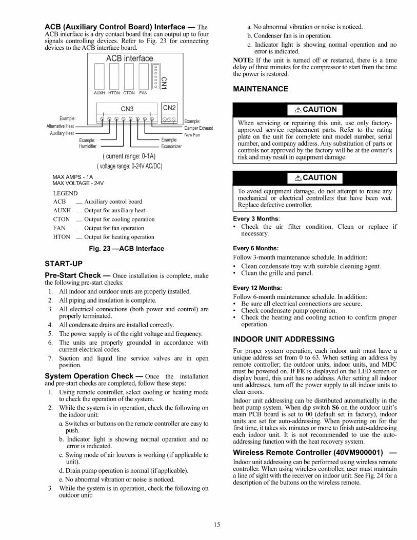
ACB (Auxiliary Control Board) Interface — TheACB interface is a dry contact board that can output up to foursignals controlling devices. Refer to Fig. 23 for connectingdevices to the ACB interface board.
Fig. 23 —ACB Interface
START-UPPre-Start Check — Once installation is complete, makethe following pre-start checks:1. All indoor and outdoor units are properly installed.2. All piping and insulation is complete.3. All electrical connections (both power and control) are
properly terminated.4. All condensate drains are installed correctly.5. The power supply is of the right voltage and frequency. 6. The units are properly grounded in accordance with
current electrical codes. 7. Suction and liquid line service valves are in open
position.
System Operation Check — Once the installationand pre-start checks are completed, follow these steps:1. Using remote controller, select cooling or heating mode
to check the operation of the system.2. While the system is in operation, check the following on
the indoor unit:a. Switches or buttons on the remote controller are easy to
push.b. Indicator light is showing normal operation and no
error is indicated.c. Swing mode of air louvers is working (if applicable to
unit).d. Drain pump operation is normal (if applicable).e. No abnormal vibration or noise is noticed.
3. While the system is in operation, check the following onoutdoor unit:
a. No abnormal vibration or noise is noticed.b. Condenser fan is in operation.c. Indicator light is showing normal operation and no
error is indicated.NOTE: If the unit is turned off or restarted, there is a timedelay of three minutes for the compressor to start from the timethe power is restored.
MAINTENANCE
Every 3 Months:• Check the air filter condition. Clean or replace if
necessary.
Every 6 Months:Follow 3-month maintenance schedule. In addition:• Clean condensate tray with suitable cleaning agent.• Clean the grille and panel.
Every 12 Months:Follow 6-month maintenance schedule. In addition:• Be sure all electrical connections are secure.• Check condensate pump operation.• Check the heating and cooling action to confirm proper
operation.
INDOOR UNIT ADDRESSINGFor proper system operation, each indoor unit must have aunique address set from 0 to 63. When setting an address byremote controller; the outdoor units, indoor units, and MDCmust be powered on. If FE is displayed on the LED screen ordisplay board, this unit has no address. After setting all indoorunit addresses, turn off the power supply to all indoor units toclear errors.Indoor unit addressing can be distributed automatically in theheat pump system. When dip switch S6 on the outdoor unit’smain PCB board is set to 00 (default set in factory), indoorunits are set for auto-addressing. When powering on for thefirst time, it takes six minutes or more to finish auto-addressingeach indoor unit. It is not recommended to use the auto-addressing function with the heat recovery system.
Wireless Remote Controller (40VM900001) —Indoor unit addressing can be performed using wireless remotecontroller. When using wireless controller, user must maintaina line of sight with the receiver on indoor unit. See Fig. 24 for adescription of the buttons on the wireless remote.
LEGENDACB — Auxiliary control boardAUXH — Output for auxiliary heatCTON — Output for cooling operationFAN — Output for fan operationHTON — Output for heating operation
ACB interface
CN3
N C
1
AUXH HTON CTON FAN
( current range: 0-1A) ( voltage range: 0-24V AC/DC)
Example:
Humidifier
Auxiliary HeatExample: Example:
Economizer
Example:Damper ExhaustNew Fan
Alternative Heat
CN2
MAX AMPS - 1AMAX VOLTAGE - 24V
CAUTIONWhen servicing or repairing this unit, use only factory-approved service replacement parts. Refer to the ratingplate on the unit for complete unit model number, serialnumber, and company address. Any substitution of parts orcontrols not approved by the factory will be at the owner’srisk and may result in equipment damage.
CAUTIONTo avoid equipment damage, do not attempt to reuse anymechanical or electrical controllers that have been wet.Replace defective controller.
16
Fig. 24 —Wireless Remote Controller (40VM900001)
Use a tool to press and hold the LOCK button for at least tenseconds, and press to activate. Click or to select anaddress and press to send the setting.To display an indoor unit address, use a tool to press and holdthe LOCK button for at least ten seconds, and press to query the addresses.
Non-Programmable Controller — When setting an address, connect only one wired controller toan indoor unit.Press ROOM TEMP and SWING simultaneously for threeseconds. If there is no address for this indoor unit, the displayshows FE# 00. See Fig. 25. Otherwise, the display shows thecurrent address of the indoor unit.
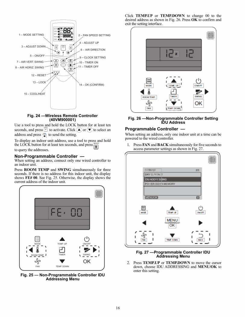
Click TEMP.UP or TEMP.DOWN to change 00 to thedesired address as shown in Fig. 26. Press OK to confirm andexit the setting interface.
Fig. 26 —Non-Programmable Controller Setting IDU Address
Programmable Controller — When setting an address, only one indoor unit at a time can bepowered to the wired controller.1. Press FAN and BACK simultaneously for five seconds to
access parameter settings as shown in Fig. 27.
Fig. 27 —Programmable Controller IDU Addressing Menu
2. Press TEMP.UP or TEMP.DOWN to move the cursordown, choose IDU ADDRESSING and MENU/OK toenter this setting.
RESET
TIMER ON
TIMER OFF
SWING AIR DIRECTION CLOCK
OKSWING
MODE FAN
AUTO
COOL
DRY
HEAT
FAN
TEMPSET
CLOCK
SETHOUR
FAN SPEED
LOCK C/H
6 – AIR DIRECTION
4 – ADJUST UP
2 – FAN SPEED SETTING
9 – CLOCK SETTING
14 – OK (CONFIRM)
10 – TIMER ON11 – TIMER OFF
1 – MODE SETTING
3 – ADJUST DOWN
12 – RESET
13 – LOCK
15 – COOL/HEAT
5 – ON/OFF
7 – AIR VERT. SWING
8 – AIR HORIZ. SWING
34
MODE
FAN TEMP. DOWN
OK
TEMP. UP ON/OFF
TIMERROOM TEMP. SWING
#
Fig. 25 — Non-Programmable Controller IDU Addressing Menu
17
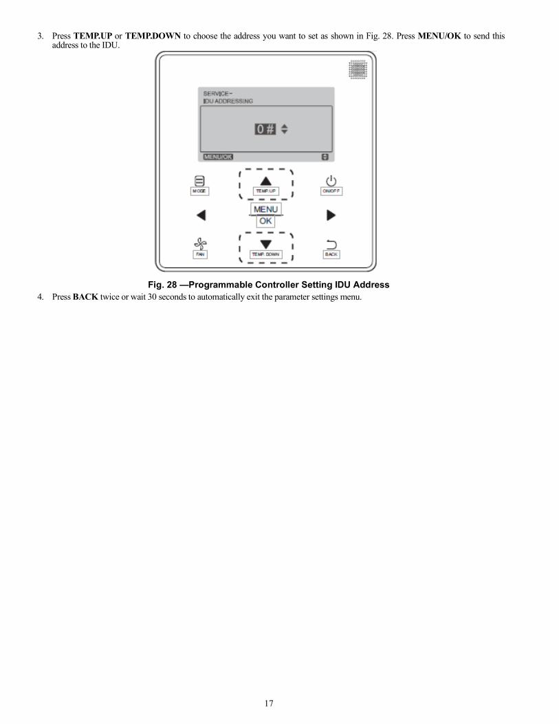
3. Press TEMP.UP or TEMP.DOWN to choose the address you want to set as shown in Fig. 28. Press MENU/OK to send thisaddress to the IDU.
Fig. 28 —Programmable Controller Setting IDU Address4. Press BACK twice or wait 30 seconds to automatically exit the parameter settings menu.

18
TROUBLESHOOTINGFigure 29 shows the display panels for 40VMW005-018 and 40VMW024-30 units. See Table 5 for a summary of display indicators.Table 6 lists problems, possible causes, and possible solutions.
Fig. 29 —40VMW Display PanelTable 5 — Display Indicators
TYPE DIGITAL DISPLAY MODE/STATUS
[NO ERROR]
Setting Temperature Starting “--” Shutdown “--” Standby “--” Timing ON“--” Timing OFF
Setting Temperature System Defrost ONSetting Temperature System Defrost OFFRoom Temperature Only Fan
ERROR
dd Heating / Cooling Mode Conflict ErrorE1 Communication Error Between Indoor and Outdoor UnitE2 Check Indoor Temperature Sensor (T1)E4 Check Evaporator Outlet Temperature Sensor (T2B)E5 Check Evaporator Temperature Sensor (T2A)E6 Check DC FanE7 EEPROM Error (Data Storage)E9 Communication Error Between Indoor Unit and Wired Controller.Eb EEV ErrorEd Outdoor Unit ErrorEE Condensate Overflow FE No Address When Powered ON For First TimeUU MDC In Auto System-Check Mode.
LEGENDACB — Auxiliary Control BoardEEPROM — Electronically Erasable Programmable Read-only MemoryEEV — Electronic Expansion ValveMDC — Multi-port Distribution Controller
40VMW005-018
LEGENDDEF. — Defrost
40VMW024-030
19
Table 6 — Troubleshooting
Replacement Parts — Provide the full unit modelnumber and unit serial number when ordering replacementparts or contacting the factory about the unit. This informationcan be found on the serial plate attached to the unit. See Fig.30.
Fig. 30 —Unit Serial Plate (Example)
DIGITAL DISPLAY DESCRIPTION POSSIBLE CAUSES POSSIBLE SOLUTIONS
dd Heating/Cooling Mode Conflict
System is in cooling or fan mode only and heating signal is received from a unit in the system.
All units should be in cooling mode for system to stay in cooling mode.
System is in heating mode and cooling signal is received from a unit in the system.
All units should be in heating mode.
E1 Communication Error Between Indoor and Outdoor Unit
Signal wires are short-circuited or disconnected.
Check or reconnect signal wire.
Signal wires close to electromagnetic source.
Distance signal wires from electromagnetic source.
PC board fault. Replace PC board.
E2, E4, E5 Check Temperature Sensor
Loose connection at port on PC board. Tighten the connection at port on PC board.Sensor is short-circuited. Using multi-meter, measure resistance of the sensor.
If the resistance is ≤ 100 ohms, change the sensor.PC board fault. Replace PC board.
E6 Check DC Fan Motor
Operating beyond limits. Check and correct external static pressure on the unit.
DC motor fault. Replace DC motor.PC board fault. Replace PC board.
E7 EEPROM Error (Data Storage) Chip or PC board fault. Replace PC board.
E9 Communication Error Between Indoor Unit and Controller
Signal wires are short-circuited or disconnected.
Check or reconnect signal wires.
Signal wires close to electromagnetic source.
Distance signal wires from electromagnetic source.
PC board fault. Replace PC board.
Eb EEV Error
EEV wires are short-circuited or disconnected.
Check or reconnect signal wire.
EEV stop. Replace EEV.PC board fault. Replace PC board.
Ed Outdoor Unit Error Outdoor unit fault. Refer to outdoor unit troubleshooting guide.
EE Condensate Overflow
Loose connection or disconnected at port on PC board.
Tighten the connection or reconnect at port on PC board.
Condensate switch float is stuck. Inspect the float.Trap slope is too steep. Adjust the trap slope.Drain pipe is too long. Adjust the length of the drain pipe.Drain pump faulty. Replace the drain pump.
FE No Address When Powered ON For First Time Indoor unit without address.
Run automatic addressing option at the outdoor unit.Use remote wireless or wired controller to readdress the indoor unit.
UU MDC In Auto System-Check Mode MDC Fault. Refer to MDC troubleshooting guide.
LEGENDEEPROM — Electronically Erasable Programmable Read-only MemoryEEV — Electronic Expansion ValveMDC — Multiport Distribution ControllerPC — Process Controller
1016V00001
AIR CONDITIONER INDOOR UNITHigh Wall
MODEL
R410AHIGHLOW
REFRIGERANT
0.45 A15 A
0.36 A20W (1/32HP)
40VMW007---3208/230V-1Ph-60Hz
320 PSIG580 PSIGDESIGN
PRESSURE
POWER SUPPLYMINIMUM CIRCUIT AMPACITYMAX FUSE OR HACR BREAKER
FAN MOTOR FLAOUTPUT
CONFORMS TO UL STD 1995CERTIFIED TO CSA STD.C22. 2 No. 236
ONLY FOR INDOOR UNIT.
SERIAL NO.
Manufacturer reserves the right to discontinue, or change at any time, specifications or designs without notice and without incurring obligations.
© 2021 Carrier. All rights reserved. Edition Date: 06/21 Form No: 40VMW-8SIA Carrier Company Printed in U.S.A. Replaces: 40VMW-7SI
20
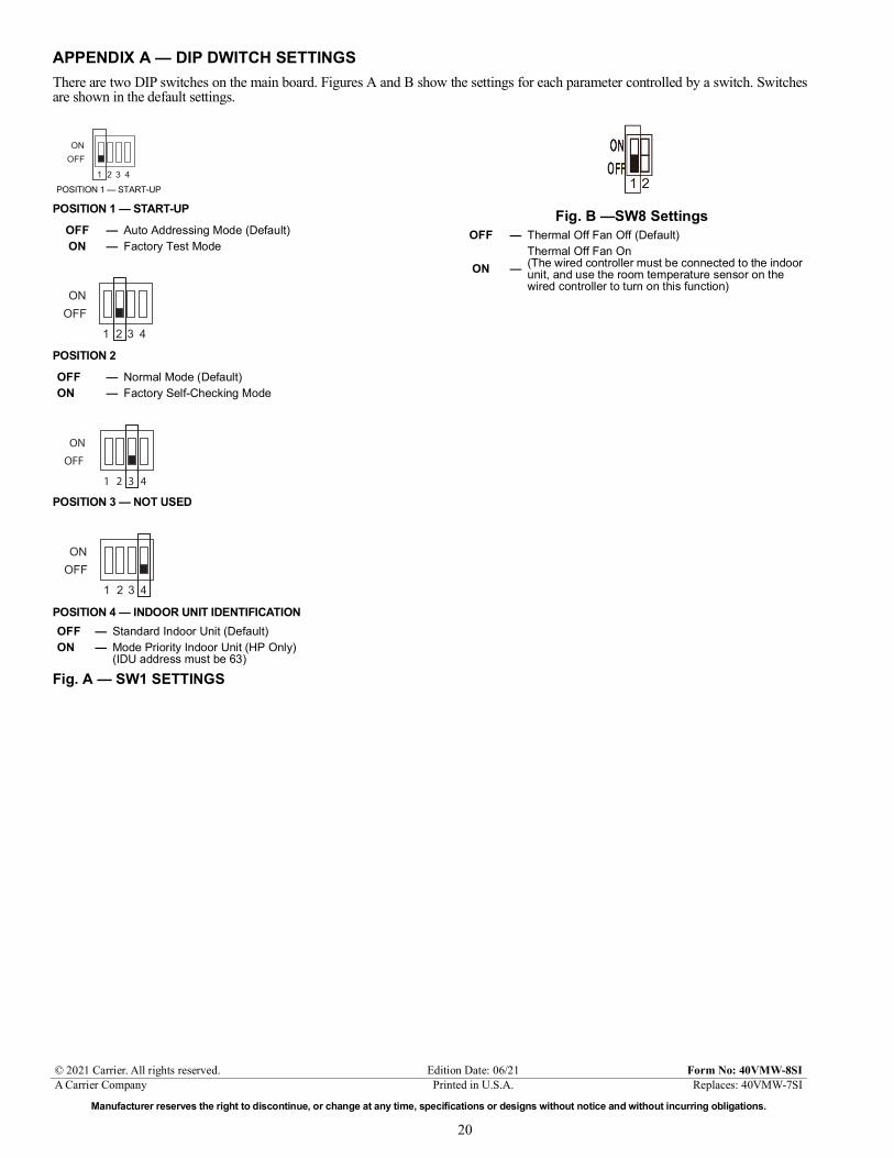
APPENDIX A — DIP DWITCH SETTINGSThere are two DIP switches on the main board. Figures A and B show the settings for each parameter controlled by a switch. Switchesare shown in the default settings.
POSITION 1 — START-UP
POSITION 2
POSITION 3 — NOT USED
POSITION 4 — INDOOR UNIT IDENTIFICATION
Fig. A — SW1 SETTINGS
Fig. B —SW8 SettingsOFF — Auto Addressing Mode (Default)ON — Factory Test Mode
OFF — Normal Mode (Default)ON — Factory Self-Checking Mode
OFF — Standard Indoor Unit (Default)ON — Mode Priority Indoor Unit (HP Only)
(IDU address must be 63)
ONOFF
1 2 3 4a40-1923
POSITION 1 — START-UP
ONOFF
1 2 3 4a40-1923
ON
OFF
1 2 3 4
ONOFF
1 2 3 4a40-1923
OFF — Thermal Off Fan Off (Default)
ON —Thermal Off Fan On(The wired controller must be connected to the indoor unit, and use the room temperature sensor on the wired controller to turn on this function)
Related Documents