1 INSTALLATION AND MAINTENANCE GUIDE FOR MARKIII MEDIUM VOLTAGE ELECTRIC FIRE PUMP CONTROLLERS MODEL SERIES: FTA2000

Welcome message from author
This document is posted to help you gain knowledge. Please leave a comment to let me know what you think about it! Share it to your friends and learn new things together.
Transcript

1
INSTALLATION AND MAINTENANCE GUIDE FOR
MARKIII MEDIUM VOLTAGE
ELECTRIC FIRE PUMP CONTROLLERS
MODEL SERIES: FTA2000

2
Electric fire pump controllers are designed to start an electric motor driven fire pump. It can either start the fire pump manually through the local start pushbutton or automatically through the sensing of a pressure drop in the sprinkler system. The fire pump controller is supplied with a pressure transducer. The fire pump can be stopped manually with the local stop pushbutton or automatically after the expiration of a field programmable timer. In both cases, stopping is only allowed if all starting causes have disappeared.
Types of Electric Fire Pump Controllers FIRE PUMP CATALOG NUMBER
MODEL No. EXAMPLE: FTA2000-AL100M
Model: FTA1930 = Electric Fire Pump Controller Start Option: A = Automatic Start with Selectable Auto or Manual Stop
Short Circuit Current Rating: L = 50 kA Rating: 100 = 100 HP
Voltage: M = 6900V, 3 Phases, 60 Hz For all starter type description consult full manual
Methods of Starting/Stopping
The controllers are available as combination automatic / non-automatic with provision for manual or automatic shutdown (an automatic shutdown is only possible after an automatic start). METHODS OF STARTING AUTOMATIC START The controller will start automatically on low pressure detection by the pressure sensor when the pressure drops below the cut-in threshold. MANUAL START The motor can be started by pressing the START push button, regardless of the system pressure. REMOTE MANUAL START The motor can be started from a remote location by momentarily closing a contact of a manual push button. REMOTE AUTOMATIC START, DELUGE VALVE START The motor can be started from a remote location by momentarily opening a contact connected to an automatic device. EMERGENCY START The motor can be started manually by using the emergency handle. This handle can be maintained in a closed position. Important: to avoid damaging the contactor, it is recommended to start the motor in this manner: 1) Shutdown the main power by using the main disconnect means, 2) Pull the emergency handle and lock it in closed position, 3) Turn the power back on by using the main disconnect means. SEQUENTIAL START In case of a multiple pump application, it may be necessary to delay the automatic (pressure drop) starting of each motor to prevent simultaneous starting of all motors. FLOW START, HIGH ZONE START The pump can be started by opening/closing a contact on the FLOW/ZONE START/STOP input. WEEKLY START The engine can be started (and stopped) automatically at the preprogrammed time.
GPXV2-Manual-EN v2.2.0.0
Introduction

3
TEST START The motor can be started manually by pressing the run test button. METHODS OF STOPPING MANUAL STOP Manual stop is done by pressing the priority STOP push button. Note that pressing the stop push button will prevent the motor from restarting as long as the button is pressed, plus a two second delay. AUTOMATIC STOP Automatic stop is possible only after an automatic start and this function has been activated. When this function is enabled, the motor is automatically stopped 10 minutes after the restoration of the pressure (above the cut-out threshold) given that no other run cause is present. FLOW STOP, HIGH ZONE STOP If the controller has been started by the FLOW/ZONE START/STOP input and the signal has returned to normal, the motor will be stopped given that no other run cause is present. EMERGENCY STOP The emergency stop is always possible in any starting condition and is done by using the main disconnecting means located on the door.
The Mark III medium voltage electric fire pump controller is cULus listed, FM certified and is intended to be installed in accordance with the latest edition of the Standard of the National Fire Protection Association for the Installation of Centrifugal Fire Pumps, NFPA20 2016 (Centrifugal Fire Pumps) and in the USA, National Electrical Code NFPA 70 others * Local Electrical Codes * *Only American applicable codes have been considered during the design of the controllers and the selection of components. Except, in some cases, the controller is also seismic approved and has been tested in accordance with the ICC-ES AC156, IBC 2015, CBC 2016, OSHPD Special Seismic Certification Preapproval – OSP and ASCE 7-10 Chapter 13 standards. Proper installation, anchoring and mounting is required to validate this compliance report. Refer to this manual and drawings to determine the seismic mounting requirements and location of the center of gravity (you may need to contact factory). The equipment manufacturer is not responsible for the specification and performance of anchorage systems. The structural engineer of record on the project shall be responsible for anchorage details. The equipment installation contractor shall be responsible for ensuring the requirements specified by the structural engineer of record are satisfied. If detailed seismic installation calculations are required, please contact the manufacturer for the performance of this work.
FCC Regulations and Radio Standards Specification (RSS) Rules To comply with FCC and Industry Canada RF exposure compliance requirements, a separation distance of at least 20 cm must be maintained between the antenna of this device and all nearby persons. This device must not be co-located or operating in conjunction with any other antenna or transmitter. This device complies with Industry Canada licence-exempt RSS standard(s). Operation is subject to the following two conditions: (1) this device may not cause interference, and (2) this device must accept any interference, including interference that may cause undesired operation of the device.
Installation

4
This device complies with part 15 of the FCC Rules. Operation is subject to the following two conditions: (1) This device may not cause harmful interference, and (2) this device must accept any interference received, including interference that may cause undesired operation. Note: This equipment has been tested and found to comply with the limits for a Class A digital device, pursuant to part 15 of the FCC Rules. These limits are designed to provide reasonable protection against harmful interference when the equipment is operated in a commercial environment. This equipment generates, uses, and can radiate radio frequency energy and, if not installed and used in accordance with the instruction manual, may cause harmful interference to radio communications. Operation of this equipment in a residential area is likely to cause harmful interference in which case the user will be required to correct the interference at his own expense. “Changes or modifications not expressly approved by the party responsible for compliance could void the user's authority to operate the equipment.”
Location The controller shall be located as close as practical to the motor it controls and shall be within sight of the motor. The controller shall be located or protected so that it will not be damaged by water escaping from the pump or pump connections. Current carrying parts of the controller shall be not less than 12 in. (305 mm) above the floor level. Working clearances around the controller shall comply with NFPA 70, National Electrical Code, Article 110 or C22.1, Canadian Electrical Code, Article 26.302 or other local codes. The controller is suitable for use in locations subject to a moderate degree of moisture, such as a damp basement. The pump room ambient temperature shall be between 39°F (4°C) and 104°F (40°C). The standard controller enclosure is rated NEMA 2. It is the installer's responsibility to insure that either the standard enclosure meets the ambient conditions or that an enclosure with an appropriate rating has been provided. Controllers must be installed inside a building and they are not designed for outside environment. The paint color may change if the controller is exposed to ultraviolet rays for a long period of time.
Mounting The fire pump controller shall be mounted in a substantial manner on a single incombustible supporting structure. Wall mounted controllers shall be attached to the structure or wall using all four (4) mounting ears provided on the controller with hardware designed to support the weight of the controller at a height not less than 12 in. (305 mm) above floor level. Floor mounted controllers shall be attached to the floor using all holes provided on the mounting feet with hardware designed to support the weight of the controller. The mounting feet provide the necessary 12 in. (305 mm) clearance for current carrying parts. For seismic applications, the mounting arrangement should be rigid wall and base only. The structural engineer of record on the project shall be responsible for anchorage details.
Storage If the controller is not installed and energized immediately, Firetrol recommend following the instructions from the chapter 3 of the NEMA ICS 15 standard.
Wiring and Connections
Water Connections The controller must be connected to the pipe system according to the latest edition of NFPA20 and also to a drain pipe. The water connections are on the left side of the controller. The connection to the system pressure is a Male ½ NPT. If a drain is present, the connection to the drain is a tapered connection for plastic tubing.
Electrical Wiring The electrical wiring between the power source and the fire pump controller shall meet the latest edition of NFPA 20, NFPA 70 National Electrical Code Article 695 or other local codes. Electrical wiring shall be typically sized to carry at least 125% of the full load current (FLC or FLA) of the fire pump motor.
5
Electrical Connections A licensed electrician must supervise the electrical connections. The dimension drawings show the area suitable for incoming power and motor connections. No other location shall be used. Only watertight hub fittings shall be used when entering the cabinet to preserve the NEMA rating of the cabinet. The installer is responsible for adequate protection of the fire pump controller components against metallic debris or drilling chips. Failure to do so may cause injuries to personnel, damage the controller and subsequently void warranty.
Energy Consumption Standby power: 10W
Sizing Incoming power terminals on the controller are suitable to accept wire based on that selection with insulation not less than 60°C. (Refer to terminal diagram for terminal sizes.) The electrical wiring between the fire pump controller and the pump motor shall be in rigid, intermediate, or liquid tight flexible metal conduit or Type MI cable and meet the requirements of NFPA 70 National Electrical Code or other local codes. The number of conductors required varies depending on the model of starter: 3-wires plus ground sized at 125% of full load current for models FTA2000.
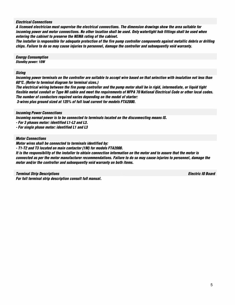
Incoming Power Connections Incoming normal power is to be connected to terminals located on the disconnecting means IS. - For 3 phases motor: identified L1-L2 and L3. - For single phase motor: identified L1 and L3
Motor Connections Motor wires shall be connected to terminals identified by: - T1-T2 and T3 located on main contactor (1M) for models FTA2000. It is the responsibility of the installer to obtain connection information on the motor and to assure that the motor is connected as per the motor manufacturer recommendations. Failure to do so may cause injuries to personnel, damage the motor and/or the controller and subsequently void warranty on both items.
Terminal Strip Descriptions Electric IO Board For full terminal strip description consult full manual.

6
Quick Start-Up Guide
The rating label is the most important label. It must be read carefully to ensure the compatibility between the controller and the installation.
Verify that the controller is installed securely on the wall, or optionally on the mounting stand.
7
Make sure to drill holes for the motor and power connections and run the cables inside the panel, all in accordance with the specifications in order to minimize interference with other equipment.
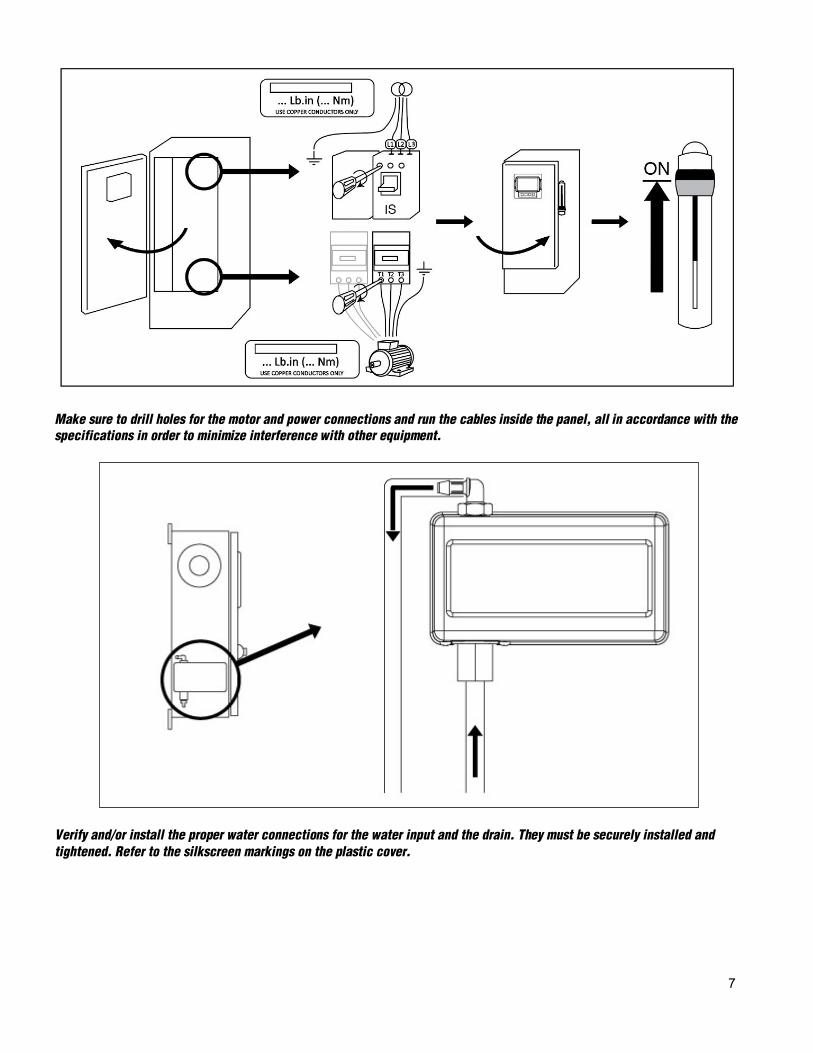
Verify and/or install the proper water connections for the water input and the drain. They must be securely installed and tightened. Refer to the silkscreen markings on the plastic cover.

8
Connect the input power and the motor on their respective terminals. Secure with the appropriate torque as indicated on the torque label and verify all connections. Secure the door in closed position then put the circuit breaker disconnecting means in ON position. Verify the readings on the controller main screen.
Once the controller has booted up, the “First Start Up” page appears. The controller will automatically detect and display the frequency of the power source. It is then possible to manually choose the frequency of the voltage. Press the padlock icon and enter a valid authorization code.

9
Verify that the normal voltage shown at L1-L2, L2-L3 and L1-L3 (nominal) is the same as what is written on the fire pump controllers nameplate. The fire pump controller will validate the nominal voltage automatically versus what it has been built for. If all is adequate green check marks will appear.

10
Press “Motor Rotation” Press the “Start” button to start the electric motor and validate that the electric motor is rotating in the correct direction. If it is not rotating in the correct direction adjust the motor connections as per below. Press the “Stop” button to stop the electric motor. Acknowledge that the motor is tunring in the right direction by checking the Check on Normal Power selector box.
Once the motor rotation has been checked, go back to the controller start-up page and press the “Verify pressure” button. WARNING! On a Wye-Delta closed transition starter, if the transition from Wye to Delta occurs (after 5 to 8 seconds depending on the motor HP), the manual stop push button will be disabled for 80 seconds. To stop the engine before the end of the 80 second delay, use the disconnecting mean handle.
11
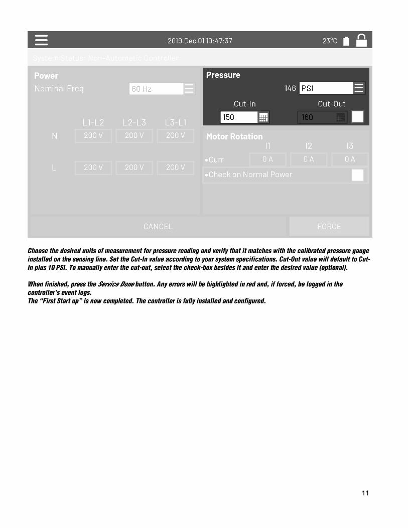
Choose the desired units of measurement for pressure reading and verify that it matches with the calibrated pressure gauge installed on the sensing line. Set the Cut-In value according to your system specifications. Cut-Out value will default to Cut-In plus 10 PSI. To manually enter the cut-out, select the check-box besides it and enter the desired value (optional).
When finished, press the Service Done button. Any errors will be highlighted in red and, if forced, be logged in the controller’s event logs. The “First Start up” is now completed. The controller is fully installed and configured.

12
From the “Home” page, verify that the displayed values are correct.
The “First Start up” is now completed. The controller is fully installed and configured.
13
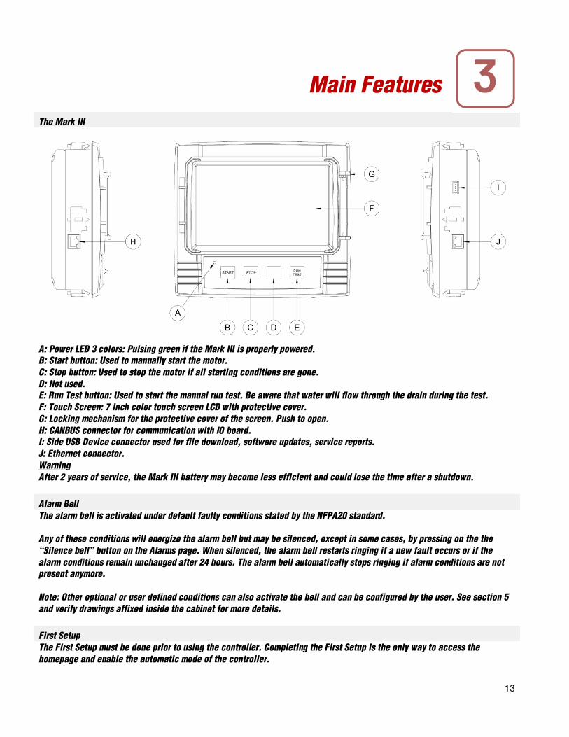
The Mark III
A: Power LED 3 colors: Pulsing green if the Mark III is properly powered. B: Start button: Used to manually start the motor. C: Stop button: Used to stop the motor if all starting conditions are gone. D: Not used. E: Run Test button: Used to start the manual run test. Be aware that water will flow through the drain during the test. F: Touch Screen: 7 inch color touch screen LCD with protective cover. G: Locking mechanism for the protective cover of the screen. Push to open. H: CANBUS connector for communication with IO board. I: Side USB Device connector used for file download, software updates, service reports. J: Ethernet connector. Warning After 2 years of service, the Mark III battery may become less efficient and could lose the time after a shutdown.
Alarm Bell The alarm bell is activated under default faulty conditions stated by the NFPA20 standard. Any of these conditions will energize the alarm bell but may be silenced, except in some cases, by pressing on the the “Silence bell” button on the Alarms page. When silenced, the alarm bell restarts ringing if a new fault occurs or if the alarm conditions remain unchanged after 24 hours. The alarm bell automatically stops ringing if alarm conditions are not present anymore. Note: Other optional or user defined conditions can also activate the bell and can be configured by the user. See section 5 and verify drawings affixed inside the cabinet for more details.
First Setup The First Setup must be done prior to using the controller. Completing the First Setup is the only way to access the homepage and enable the automatic mode of the controller.
Main Features

14
Mark III: Manual Rebooting Method If required, here is the procedure to manually reboot the Mark III: 1- Turn OFF all disconnecting means to de-energize the Mark III. The Mark III's screen should turn black. 2- Press the stop button or wait until the Mark III's LED extinguishes. 3- Wait 10 seconds. 4- Turn ON all disconnecting means.
Pressure Transducer Test The controller will test the pressure transducer at least once a week if no manual run test or no weekly test has been conducted. During the test, the pressure reading will drop to zero but the controller will not see it as a starting request. This pressure drop will be recorded in the “Pump Curve” page and in the logs with the message.
Home (Menu) Home
The home page displays all controller statuses and important values of the controller. This includes all voltages, currents, pressures, motor state and status Navigation bar: Pressing this icon will open a navigation menu on the left side of the screen:
1. Go to Home page 2. Go to Alarms page 3. Go to Configuration page 4. Go to History page 5. Go to Service page 6. Go to Download Manual page
Home

15
7. Select Controller Language System Status: Display the overwall system status. For more details, refer to the system status page. Motor power voltage. Each box represents an individual phase voltage between the two adjacent lines. Current. Each circle represents an individual line current. Motor contacts. An animation shows the contactor opened or closed depending on the signal sent to the main coil. The pressure gauge: It allows for a precise reading of the actual system pressure. The cut-in and cut-out are represented by a red and green triangle on the gage, allowing a quick comparison between the actual pressure and the set points.
Screen Saver After 5 minutes of inactivity on the Mark III, the screen will dim it's brightness to 25%. After 10 minutes of inactivity on the Mark III, the “Black Screen” screen saver will activate. Its goal is to expand the lifetime of the LCD screen. The screen saver will be instantly deactivated if the engine is running or if an alarm is activated. To manually deactivate it, simply touch the screen or any membrane button. After deactivation, the screen saver will always redirect to the “Home” page. It will also log off any user by resetting the security level to 0 and save any new modifications to the settings.
Alarms (Menu) Configuration > Advanced > Alarms For full alarm list and information consult the full manual, Digitally available, see “Download manual” in section 9
Config (Menu) Config For additional information about configuration please consult the full manual, Digitally available, see “Download manual” in section 9
History (Menu) History
Alarms
Configuration
History

16
This page is used to access all data related to events, statistics, pressure history, power logs and the downloading of this information via one of the two USB ports. -Events: This button leads to the “Events” page, which displays the events from the most recent 500 logs. Each event log contains the date and time of occurrence as well as a brief description of the event. -Pressure/Power Curves: This button leads to the “Pressure Curves” / “Power Curves” page accordingly, which displays all relevant pressure/power information from the most recent 500 logs. -Saved Logs: This button leads to a page where past logs can be viewed. -Pump Curve: This button leads to the “Pump Curves” page. -Statistics: This button leads to the “Statistics” page, which leads to “All Time Statistics”, “First Service Statistics” and “Last Service Statistics” pages. -Download: This button leads to the “Download” page, which allows the user to download information, including the user manual, drawings, logs, statistics and configuration. For additional information on the History feature refer to the full manual.
Service
Informations on how to reach technical support, concerning the commissioning date, the last service date and the next service due date is available on this page. It is the client responsibility to make sure that the proper maintenance is done on the controller. A reminder for the “Service” can be selected from these options: OFF, ½ year, 1 year, 1 ½ years, 2 years and 3 years. The next service will be determined using the last service and the chosen service interval. This service must be done by an accredited technician. A proper password must be enter for the “Service Done” button to be available. This button should only be pressed by an authorized person after a completed service. The “Live View” page is where the user can grant or refuse the remote access demands. The “Nameplate Information” page contains all the information found on the nameplate. The Jockey Pump Cut-Out and Cut-In can be set on this page. It is possible to install a custom Service card on this page. Contact Firetrol for more information.
Service

17
Pressing on the question mark on the Mark III will redirect to the download page. A pdf version of the manual can be downloaded on an USB device.
The language displayed on the Mark III can be selected on this page.
Download Manuals
Language
Technical Documents

18
Firetrol Inc.
+1 919 460 5200
3412 Apex Peakway, Apex
NC, 27502
Related Documents