Munich Bridge Assessment Conference MBAC 2007 N. Gebbeken, M. Keuser, I. Mangerig Munich, 09.-12 July 2007 1 INSPECTION, MAINTENANCE AND REPLACEMENT OF STAY CABLES Reiner Saul * and Karl Humpf † *† Leonhardt, Andrä und Partner, Beratende Ingenieure VBI, GmbH Lenzhalde 16, 70192 Stuttgart, Germany e-mail: [email protected] , [email protected] , web page: www.unibw-mbac.net Key words: Locked coil ropes, parallel wire cables, parallel strand cables, inspection, maintenance, replacement. Abstract. After a brief survey of the development of cable-stayed bridges, the cable types mostly used for these bridges are described: locked coil ropes, parallel wire cables and parallel strand cables; Special emphasis is given to the corrosion protection. Furthermore, general requirements and special techniques for the inspection of stay cables are presented: visual, electromagnetic, ultrasonic and X-ray inspection. Serious damages observed in several of the early cable-stayed bridges are described as well as the corresponding maintenance work and the replacement of some or of all cables. The damages have caused improvements of the global design, the structural detailing, the sizing and the corrosion protection which aim to minimize the inspection and maintenance cost in the future. The state of the art of the design, inspection and maintenance of stay cables is given in the actual national and international codes, e. g. - in Germany into: TL Seile (Technical specifications for ropes) 1994 RKS Seile + TLKS Seile (Guidelines and technical specifications for the corrosion protection of ropes) 1983 DIN Fachbericht 103 (German version of Eurocode 3, Part 2) - internationally: Recommendations for Stay Cable Design, Testing and Installation. Post-Tensioning Institute, USA, 4 th Edition 2001 fib: Acceptance of stay cable systems using prestressing steels. bulletin 30, Lausanne January 2005. Cables fabricated, protected, inspected and maintained according to these standards will have a lifetime equal to that of bridges they support.

Inspection, Maintenance and Replacement
Oct 26, 2014
Welcome message from author
This document is posted to help you gain knowledge. Please leave a comment to let me know what you think about it! Share it to your friends and learn new things together.
Transcript

Munich Bridge Assessment Conference MBAC 2007
N. Gebbeken, M. Keuser, I. Mangerig Munich, 09.-12 July 2007
1
INSPECTION, MAINTENANCE AND REPLACEMENT OF STAY CABLES
Reiner Saul* and Karl Humpf†
*† Leonhardt, Andrä und Partner, Beratende Ingenieure VBI, GmbH Lenzhalde 16, 70192 Stuttgart, Germany
e-mail: [email protected], [email protected], web page: www.unibw-mbac.net
Key words: Locked coil ropes, parallel wire cables, parallel strand cables, inspection, maintenance, replacement.
Abstract. After a brief survey of the development of cable-stayed bridges, the cable types mostly used for these bridges are described: locked coil ropes, parallel wire cables and parallel strand cables; Special emphasis is given to the corrosion protection. Furthermore, general requirements and special techniques for the inspection of stay cables are presented: visual, electromagnetic, ultrasonic and X-ray inspection. Serious damages observed in several of the early cable-stayed bridges are described as well as the corresponding maintenance work and the replacement of some or of all cables. The damages have caused improvements of the global design, the structural detailing, the sizing and the corrosion protection which aim to minimize the inspection and maintenance cost in the future. The state of the art of the design, inspection and maintenance of stay cables is given in the actual national and international codes, e. g.
- in Germany into: TL Seile (Technical specifications for ropes) 1994 RKS Seile + TLKS Seile (Guidelines and technical specifications for the corrosion protection of ropes) 1983 DIN Fachbericht 103 (German version of Eurocode 3, Part 2)
- internationally: Recommendations for Stay Cable Design, Testing and Installation. Post-Tensioning Institute, USA, 4th Edition 2001 fib: Acceptance of stay cable systems using prestressing steels. bulletin 30, Lausanne January 2005.
Cables fabricated, protected, inspected and maintained according to these standards will have a lifetime equal to that of bridges they support.
Reiner Saul and Karl Humpf
2
1 ON THE DEVELOPMENT OF CABLE-STAYED BRIDGES
1.1 General The first cable-stayed bridge in Germany, the Büchenauer Bridge in Bruchsal, was built in
1956. It has a rather moderate span of 58,8 m and a steel composite bridge deck. Starting with the construction of the Düsseldorf North Bridge in 1959, cable-stayed bridges
across the Rhine River were built with spans ranging from 175 to 368 m. The majority of these bridges has an all-steel bridge deck; for 3 bridges, the combination main span from steel and side spans from prestressed concrete has been chosen. Smaller bridges, especially pedestrian bridges, have also been built with an all-concrete deck.
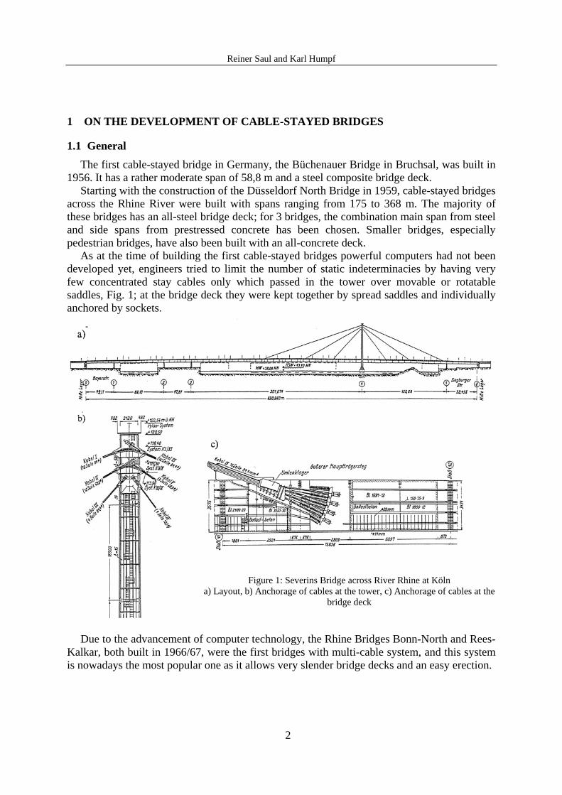
As at the time of building the first cable-stayed bridges powerful computers had not been developed yet, engineers tried to limit the number of static indeterminacies by having very few concentrated stay cables only which passed in the tower over movable or rotatable saddles, Fig. 1; at the bridge deck they were kept together by spread saddles and individually anchored by sockets.
Figure 1: Severins Bridge across River Rhine at Köln a) Layout, b) Anchorage of cables at the tower, c) Anchorage of cables at the
bridge deck
Due to the advancement of computer technology, the Rhine Bridges Bonn-North and Rees-Kalkar, both built in 1966/67, were the first bridges with multi-cable system, and this system is nowadays the most popular one as it allows very slender bridge decks and an easy erection.

Reiner Saul and Karl Humpf
3
Up to about 1975, the majority of cable-stayed bridges has been built in Europe, especially in Germany; actually, the focus of cable-stayed bridge construction is in South-East Asia, and the Stonecutters Bridge in Hong Kong will be the first bridge with a main span exceeding 1000 m.
1.2 Cable Types As manifold as the static system and the cable arrangement are the structural detailing and
design of the cables. Nevertheless, only two cable types have world-wide achieved broad application: the locked coil ropes and the parallel wire or parallel strand cable, using prestressing wires and strands, Fig. 2, where the main characteristic of both cable types are also given.
a)
b) c)
d) E [105 N/mm²] 1,65 2,05 1,95 zul. σ [N/mm²] 0,42 x 1570 = 660 0,45 x 1670 = 750 0,45 x 1770 = 800 zul. Δσ [N/mm²] 150 200 200 E / zul. σ [÷] 250 276 244
Figure 2: Cross sections of stay cables a) Modern locked coil rope, b) Parallel wire cable, c) Parallel strand cable, d) Main characteristics
Being Germany a country with a strong rope industry, the vast majority of Gemran cable-stayed bridges has locked coil ropes. Parallel wire cables have been used for the Rhinebridge Mannheim-Ludwigshafen and pedestrian bridges in Stuttgart, Villingen and Mannheim, only, and the first German bridge with parallel strand cables, the Ziegelgraben Bridge between Stralsund and the island Rügen, will be opened to traffic in fall 2007.
Abroad, instead, most cable-stayed bridges have either parallel wire or parallel strand cables.
2 INSPECTION
2.1 General The design and construction of bridges is governed all over the world by codes like
AASHTO, British Standards or, in Germany, by a “building” of individual codes, the most important being
DIN Fachbericht 101 Load Assumptions DIN Fachbericht 103 Steel Bridges DIN Fachbericht 102 Concrete Bridges DIN Fachbericht 104 Steel Composite Bridges

Reiner Saul and Karl Humpf
4
ZTV-ING Additional Technical Prescriptions for Engineering Structures DIN 1076 Observation and Inspection of Engineering Structures BWPrüf Expert System for Compilation and Evaluation of the Inspections acc. to DIN 1076 RAB-Brü90 Guidelines for the Design of Bridges for Ease Access, Checking and Maintenance According to all these codes, bridges have to be designed not only for ultimate load
capacity, serviceability, robustness and durability, but also for easy and economical regular inspection and maintenance.
2.2 Deficiencies of Older Bridges In bridges built until about 1975, one or more of the following deficiencies are
encountered: - no or difficult access to bearings and expansion jointing - no precautions for the replacement of bearings - box girders with unsufficient dimensions and/or without illumination - lack of inspection walkways inside the bridge and of access of vehicles to the
undersight of the bridge - cables built up from various locked coil ropes without access to the inner ropes.
2.3 Requirements of DIN 1076 DIN 1076 specifies the following types of inspection - Regular Control by Road Inspectors
- permanently for safety of crash barriers, traffic lights, paving, expansion jointing and the like
- on special occasions e. g. accidents, floods
- Inspections by specially trained staff - simple inspections at 3 years intervals
all visible elements, like painting of steel structures, surface of concrete structures, dewatering systems and the like
- main inspections at 6 year intervals check of hidden elements and for hidden defects like loose bolts and rivets, cracks of welds and adjacent material or of concrete, corrosion of rebars and tendons, elements protected by boots, score of piers etc.
The results of all these tests and documents prepared during the construction are compiled in a bridge book, where also the need of maintenance work before the next inspection is specified.

Reiner Saul and Karl Humpf
5
2.4 Special Aspects for Stay Cables
2.4.1 Visual Inspection
The visual inspection is the most important part of all inspections. The primary objective of a visual examination is to determine the condition of the cable and to find eventual exterior damages of the corrosion protection. Furthermore, visible changes of this surface frequently indicate internal damage.
The cable should allow unobstructed access between the cable difficult or impossible. It should be possible at least to inspect the entrance of the cable into the socket by means of an endoscope connected to a video recorder, as about 80 % of all damages are encountered in this area.
The visual inspection is carried out from inspection trolleys which may travel on each cable, on the upper cable only or on an auxiliary cable. The German Ministry of Traffic has developed an equipment which may be adapted to all German cable-stayed bridges.
2.4.2 Electromagnetic Inspection
Electromagnetic (EM) inspections allow examinations of the interior of the cable. These inspections show external as well as internal cracked or broken wires, abrasion and most important: corrosion in the inside of a cable or on the outside under an apparently undamaged corrosion protection coating. Practical instruments for in-service wire rope inspections were first developed in 1930 for e.g. the ropes used in the coal mines or in cable cars. Instruments which can simultaneously detect localized faults and measure loss of metallic cross-sectional area were used for the inspection of bridge cables in Germany since about 1970, Fig. 3, and nowadays instruments for all cable types are available.
The instruments are pulled along the
cable with a winch and the test signals can be recorded or stored and processed.
Some bridge cables have been inspected repeatedly as the graphs showed serious problems. In a specific cable, 2 broken wires were detected in 1984; in 1986, the distance between the wire ends had increased due to dynamic stresses; and in 1990, an incipient wire break was detected in the same area. The comparison of different EM graphs recorded along the time allows, hence, estimating the remaining lifetime of the cable.
Figure 3: Scheme of Electromagnetic inspection

Reiner Saul and Karl Humpf
6
2.4.3 X-Ray Inspection
X-ray inspection – with cobalt radiation – has been applied to various cables at an experimental stage. Today it is feasible for the free length of the cable but not for the anchorage zone. The advantage of having a permanent document is counteracted by the extremely long exposure time.
2.4.4 Ultrasonic Inspection
In order to detect eventual wire cracks inside of cable anchorages, special ultrasonic inspection methods have been developed which allow to control the entrance of the cable into these elements, Fig. 4, and over the entire embedded length.
Figure 4: Scheme of ultrasonic inspection
2.4.5 Inspection of Test Specimen
In some bridges, test specimens have been stored under similar conditions as the real cables. A periodic inspection of these specimens allows conclusions on the state of the cables.
In cables built up from monostrands, individual strands may be extracted, tested and replaced by new strands.
3 MAINTENANCE
3.1 Locked Coil Ropes The maintenance of locked coil ropes consists basically of a repainting. For old ropes, with
a base layer of red lead, the repainting has to be done whilst the base layer is still granting a protection of the rope as sandblasting of the red lead requires an expensive protection of the environment.
In some bridges with concentrated cables, the clamps in front of the anchorages have been eliminated in order to give access to the inner ropes.
3.2 Parallel Wire and Strand Cables The outer PE-pipes may be reinforced by a plastic tape, s. point 4.3; and in parallel strand
cables with a “wedge only” anchorage, s. point 5.6, individual strands may be replaced.

Reiner Saul and Karl Humpf
7
4 DAMAGES OF STAY CABLES AND REPAIR THEREOF
4.1 Locked Coil Ropes
4.1.1 Köhlbrand Bridge, Hamburg
The Köhlbrand Bridge was built from 1969 to 1974. Its 88 locked coil ropes with diameters ranking from 54 mm to 104 mm had the following corrosion protection
- bare wires, as engineers at the time were frightened by hydrogen embrittlement due to galvanizing
- inner filling with redlead and linseed oil
- 2 base layers of redlead and phthalate resin with a thickness of 50 µ each.
During a 1976 inspection of the cables, 25 broken wires were detected, Fig. 5. An in-depth analysis of the possible causes of these damages showed that the following factors had contributed:
Figure 5: Köhlbrand Bridge at Hamburg: Lower cable
anchorage with broken wires
a) Structural detailing: The cable anchorages are positioned not in the tangent, but in the
secant. This causes secondary stresses due to the bending stiffness of the ropes. The sockets and the entrance of the cables into the sockets were not protected against the access of humidity and splash-water, so that aggressive agents were concentrated in small cracks and gaps of the socket casting at this critical point. The ropes were protected by lead collars against direct contact with the anchor beams. Due to its electric potential difference lead facilitates the corrosion of steel.
b) Sizing: Although there is a very heavy truck traffic on this light-weight steel bridge, a sizing against fatigue was not made as DIN 1073 did not require it at that time. Frequent cable oscillations with great amplitudes were observed, which could not be explained by vortex shedding but as anchorage excitation due to fgirder = 2fcable. In some cables the forces due to permanent loads were so small that in combination with unfavourable live load – and assuming constant cable stiffness – compression was obtained. The cables then cease to be locked and humidity may penetrate into them.
c) Design and application of the corrosion protection: As mentioned earlier, the wires were not galvanized. During the hot metal casting of the sockets with temperatures of about 425°C, the inner corrosion protection in front of the sockets was burned. Due to the shims, bearing bars etc. in front of the sockets, the outside painting in this area is poor.

Reiner Saul and Karl Humpf
8
All these factors have contributed to the wire breaks, but an exact quantification cannot be given due to the rather complex interaction among them. Nevertheless, the fact that 22 out of the 25 broken wires were found at the lower cable anchorages indicates the outstanding contribution of the de-icing salt.
As all cables were subject to the mentioned defects, the bridge had to be re-roped completely.
4.1.2 Maracaibo Bridge, Venezuela
The bridge across the Lake of Maracaibo, Venezuela, was built from 1959 to 1962. Its 5 identical main spans of 235 m are stayed with single concentrated cables consisting of 16 locked coil ropes Ø 74 mm. The corrosion protection of these cables was basically the same as for the original cables of the Köhlbrand bridge.
At the bridge deck, the ropes are running through pipes and are anchored to a concrete cross girder. The pipes were filled with asphalt and sealed at their upper ends by means of wooden plugs and neoprene boots.
Between 1974 and 1978, several broken wires were detected. An in-depth inspection at the end of 1978 showed more than 500 broken wires, Fig. 6, and in early 1979 3 ropes had broken completely.
The damages were caused mainly by two phenomena: The general lack of maintenance of the painting in the hot maritime climate; and the neoprene boots had not been reinstalled after an inspection, so that a permanently humid microclimate was established underneath the wooden plugs.
Figure 6: Maracaibo Bridge, Broken Wires
Due to the fast progress of the deterioration, the cables were first reinforced with tendons; later, the bridge was completely reroped. In order to do so, new cable anchorages had to be installed on top of the cable saddles at the towers.
4.2 Parallel Wire Cables
4.2.1 Zárate-Brazo Largo Bridges across River Paraná, Argentina
The two cable-stayed bridges across the Paraná River have main spans of 330 m and were completed in 1976 and 1977. The 144 parallel wire stay cables have a corrosion protection consisting of PE-pipes injected with cement grout. At the end of 1978 longitudinal cracks occurred in the PE-pipes of the parallel wire cables. A thorough investigation indicated that a systematic mistake during the injection with cement grout was a main reason for the cracks. Grouting took place in sections. After the grout of the lower section was hardened, the next section above was grouted. Due to the pressure of the new grout the PE-pipe widened and

Reiner Saul and Karl Humpf
9
grout was flowing into the annular space between the already hardened grout and the widened PE-pipe below. The PE-pipes were overstrained by up to 8 % and thus had to crack. Another, less important reason for the cracks was that the grouting took place during high temperatures which caused circumferential tensile stresses at later low temperatures.
In order to preserve the long-term corrosion protection, the PE-pipes were wrapped with a base layer of Filament Tape for strengthening the PE-pipes and a layer of white Tedlar Tape on top for protection against UV-radiation.
Nevertheless, humidity has still penetrated into the cables and has caused severe corrosion in front of the lower socket, where the cables had, over a length of about 5 cm, a passive corrosion protection (tar-polyurethane) only. In …, one cable broke and since then half of the cables has been replaced by parallel strand cables.
4.2.2 Luling Bridge, Louisiana, USA
The cable-stayed steel bridge crosses the Mississippi at Luling with a main span of 377 m. The 72 parallel wire cables have the same corrosion protection as those of the Zárate-Brazo Largo Bridges.
The stay cables remained on reels for only about three months because difficulties encountered during cable testing delayed the cable fabrication. Several butt welds of the PE-pipes failed on the reel and during unreeling. The failures on the reel were attributed to a malfunctioning welding equipment. The failures during uncoiling were traced to low temperatures. As a consequence, sheds with space heaters were provided for the coils which brought the temperature of the PE-pipes to at least 20°C during uncoiling. This measure proved to be successful.
The grouting of the cables was completed in September 1983. In April 1985 longitudinal cracks were detected in two backstay cables. During the following winter more cracks developed. A thorough investigation of the reasons for the cracks revealed that overstraining of the PE-pipes up to 8,9 % during grouting was the main cause. Additional reason was grouting during very hot weather.
The repair was done similarly as for the ZBL Bridges mentioned before. Contrary to these bridges no wire or cable breaks have been reported so far.
5 IMPROVEMENT OF THE DESIGN, STRUCTURAL DETAILS, SIZING AND CORROSION PROTECTION
5.1 General The damages described above were mainly due to gross errors, caused by lack of
experience during the fast development and profileration of cable-stayed bridges in the past. They can be avoided in the future, if the following points are duly taken into account in the design, specifications, construction and maintenance of cable-stayed bridges.

Reiner Saul and Karl Humpf
10
5.2 Design a) Bridge system: The main requirement with respect to an easy maintenance is that all
cables can be freely inspected and, if necessary, individually exchanged. This has led from the systems with only a few concentrated cables used in the past to the modern multicable systems, which are advantageous also for erection.
b) Elimination of oscillations: Wind or otherwise excited osciallations of the cables have to be avoided by means of dampers.
5.3 Structural Details a) Support of sockets: The cables should be accessible – at least inspectable – over their
entire length between the sockets. The sockets should, therefore, not be supported at their front face, but e.g. by nuts, hammerheads etc.
b) Entrance of cables to the bridge deck: The entrance of the cables to the bridge deck must be hermetically sealed, e.g. by neoprene boots.
5.4 Sizing a) Minimum cable stress: The cable forces under permanent loads must be chosen in such
a way that – in combination with the governing position of the live loads – the cables do not slacken. With such a slackening, the locked coiled ropes are not tight anymore.
b) Check for fatigue: As the fatigue strength of all bridge cable systems is relatively poor in comparison with their static strength, they must be checked for fatigue, due to live loads as well as due to vibrations (if no dampers are installed). Not only the variation of the normal force, but also that of the angle has to be considered.
c) Load case “Cable Exchange”: The possibility of a cable exchange has to be taken into account already during the design in order to avoid costly strengthening of the structure in the future. Nevertheless, for this special situation a reduction of the live load or the safety factor – or increased allowable stresses – may be considered.
5.5 Locked Coil Ropes
The following requirements must be considered a must:
a) All wires have to be hot-dip galvanized with about 280 g/m² or 45 µ.
b) The protective system has to consist of e.g. - filling of the inner voids with polyurethane with zinc dust or linseed oil with redlead - two outer basic coatings of polyurethane with zinc chromates with a thickness of 100 µ each,
Reiner Saul and Karl Humpf
11
- two finishing coatings of polyurethane with iron glimmer, with a thickness of also 100 µ each.
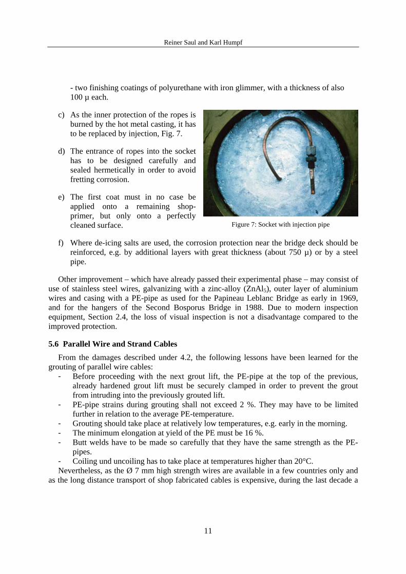
c) As the inner protection of the ropes is burned by the hot metal casting, it has to be replaced by injection, Fig. 7.
d) The entrance of ropes into the socket has to be designed carefully and sealed hermetically in order to avoid fretting corrosion.
e) The first coat must in no case be applied onto a remaining shop-primer, but only onto a perfectly cleaned surface.
Figure 7: Socket with injection pipe
f) Where de-icing salts are used, the corrosion protection near the bridge deck should be reinforced, e.g. by additional layers with great thickness (about 750 µ) or by a steel pipe.
Other improvement – which have already passed their experimental phase – may consist of use of stainless steel wires, galvanizing with a zinc-alloy (ZnAl5), outer layer of aluminium wires and casing with a PE-pipe as used for the Papineau Leblanc Bridge as early in 1969, and for the hangers of the Second Bosporus Bridge in 1988. Due to modern inspection equipment, Section 2.4, the loss of visual inspection is not a disadvantage compared to the improved protection.
5.6 Parallel Wire and Strand Cables
From the damages described under 4.2, the following lessons have been learned for the grouting of parallel wire cables:
- Before proceeding with the next grout lift, the PE-pipe at the top of the previous, already hardened grout lift must be securely clamped in order to prevent the grout from intruding into the previously grouted lift.
- PE-pipe strains during grouting shall not exceed 2 %. They may have to be limited further in relation to the average PE-temperature.
- Grouting should take place at relatively low temperatures, e.g. early in the morning. - The minimum elongation at yield of the PE must be 16 %. - Butt welds have to be made so carefully that they have the same strength as the PE-
pipes. - Coiling und uncoiling has to take place at temperatures higher than 20°C. Nevertheless, as the Ø 7 mm high strength wires are available in a few countries only and
as the long distance transport of shop fabricated cables is expensive, during the last decade a

Reiner Saul and Karl Humpf
12
shift from shop fabricated parallel wire cables to in situ fabricated parallel strand cables could be observed around the world. The corrosion protection of these cables consists of
- a galvanizing of the wires with >220 g/m² - a 1 mm PE sheath with wax filling - an HDPE-pipe with a wall thickness of 1/18 of the outer diameter and an extruded
Screwton helix in order to suppress aeolian vibration of the cables. The individual strand may be anchored in the sockets - by wedges for permanent loads and by wedges and a chemical compound, e.g. epoxy
resin, for live loads - by high fatigue wedges only for all loads. The latter anchorage allows the replacement of individual strands and may be considered
the state of the art of stay cables using prestressing steels, Fig. 8
Figure 8: Parallel strand cables with “wedge only” anchorage
6 SUMMARY The corrosion protection for the most commonly used types of stay cables – locked coild
ropes and parallel wire/strand cables – has reached a high state-of-the-art. The lessons learned from damages in early applications as well as the knowledge gained from a multitude of tests conducted all over the world have been put to practical use. Properly designed, fabricated, installed and maintained stay cables have a life expectancy similar to that of conventional bridges.
In view of the elevate cost of the replacement of a cable, quality requirements must be the decisive consideration for the selection of stay cables; with other words: not the lowest construction cost, but the minimum life-time cost has to be the governing criterion in the selection.
Equally important is a thorough, knowledgeable inspection at regular intervals over the life time of the bridge which detects and corrects possible corrosion problems at an early stage. The tools herefore are available, but we have to give to inspection and maintenance – which are unattractive for politicians – their own rights and use the tools!
Related Documents