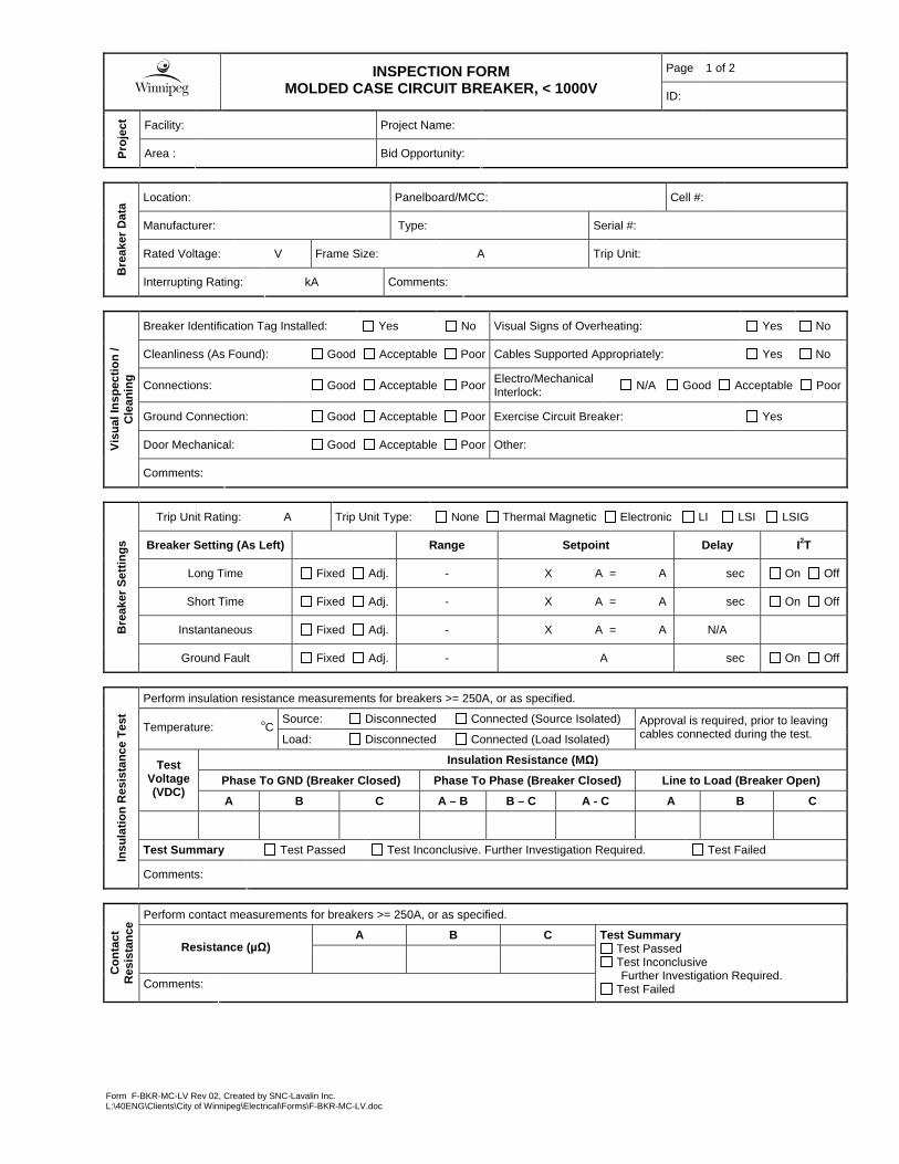
Form F-BKR-MC-LV Rev 02, Created by SNC-Lavalin Inc. L:\40ENG\Clients\City of Winnipeg\Electrical\Forms\F-BKR-MC-LV.doc Page 1 of 2 INSPECTION FORM MOLDED CASE CIRCUIT BREAKER, < 1000V ID: Facility: Project Name: Project Area : Bid Opportunity: Location: Panelboard/MCC: Cell #: Manufacturer: Type: Serial #: Rated Voltage: V Frame Size: A Trip Unit: Breaker Data Interrupting Rating: kA Comments: Breaker Identification Tag Installed: Yes No Visual Signs of Overheating: Yes No Cleanliness (As Found): Good Acceptable Poor Cables Supported Appropriately: Yes No Connections: Good Acceptable Poor Electro/Mechanical Interlock: N/A Good Acceptable Poor Ground Connection: Good Acceptable Poor Exercise Circuit Breaker: Yes Door Mechanical: Good Acceptable Poor Other: Visual Inspection / Cleaning Comments: Trip Unit Rating: A Trip Unit Type: None Thermal Magnetic Electronic LI LSI LSIG Breaker Setting (As Left) Range Setpoint Delay I 2 T Long Time Fixed Adj. - X A = A sec On Off Short Time Fixed Adj. - X A = A sec On Off Instantaneous Fixed Adj. - X A = A N/A Breaker Settings Ground Fault Fixed Adj. - A sec On Off Perform insulation resistance measurements for breakers >= 250A, or as specified. Source: Disconnected Connected (Source Isolated) Temperature: o C Load: Disconnected Connected (Load Isolated) Approval is required, prior to leaving cables connected during the test. Insulation Resistance (MΩ) Phase To GND (Breaker Closed) Phase To Phase (Breaker Closed) Line to Load (Breaker Open) Test Voltage (VDC) A B C A – B B – C A - C A B C Test Summary Test Passed Test Inconclusive. Further Investigation Required. Test Failed Insulation Resistance Test Comments: Perform contact measurements for breakers >= 250A, or as specified. A B C Resistance (μΩ) Contact Resistance Comments: Test Summary Test Passed Test Inconclusive Further Investigation Required. Test Failed

Welcome message from author
This document is posted to help you gain knowledge. Please leave a comment to let me know what you think about it! Share it to your friends and learn new things together.
Transcript
Form F-BKR-MC-LV Rev 02, Created by SNC-Lavalin Inc. L:\40ENG\Clients\City of Winnipeg\Electrical\Forms\F-BKR-MC-LV.doc
Page 1 of 2
INSPECTION FORM
MOLDED CASE CIRCUIT BREAKER, < 1000V ID:
Facility: Project Name: P
roje
ct
Area : Bid Opportunity:
Location: Panelboard/MCC: Cell #:
Manufacturer: Type: Serial #:
Rated Voltage: V Frame Size: A Trip Unit:
Bre
aker
Dat
a
Interrupting Rating: kA Comments:
Breaker Identification Tag Installed: Yes No Visual Signs of Overheating: Yes No
Cleanliness (As Found): Good Acceptable Poor Cables Supported Appropriately: Yes No
Connections: Good Acceptable Poor Electro/Mechanical Interlock:
N/A Good Acceptable Poor
Ground Connection: Good Acceptable Poor Exercise Circuit Breaker: Yes
Door Mechanical: Good Acceptable Poor Other: Vis
ual I
nspe
ctio
n /
Cle
anin
g
Comments:
Trip Unit Rating: A Trip Unit Type: None Thermal Magnetic Electronic LI LSI LSIG
Breaker Setting (As Left) Range Setpoint Delay I 2T
Long Time Fixed Adj. - X A = A sec On Off
Short Time Fixed Adj. - X A = A sec On Off
Instantaneous Fixed Adj. - X A = A N/A Bre
aker
Set
tings
Ground Fault Fixed Adj. - A sec On Off
Perform insulation resistance measurements for breakers >= 250A, or as specified.
Source: Disconnected Connected (Source Isolated) Temperature: oC
Load: Disconnected Connected (Load Isolated)
Approval is required, prior to leaving cables connected during the test.
Insulation Resistance (M Ω)
Phase To GND (Breaker Closed) Phase To Phase (Break er Closed) Line to Load (Breaker Open) Test
Voltage (VDC)
A B C A – B B – C A - C A B C
Test Summary Test Passed Test Inconclusive. Further Investigation Required. Test Failed
Insu
latio
n R
esis
tanc
e T
est
Comments:
Perform contact measurements for breakers >= 250A, or as specified.
A B C Resistance (µ Ω)
Con
tact
R
esis
tanc
e
Comments:
Test Summary Test Passed Test Inconclusive
Further Investigation Required. Test Failed

Page 2 of 2
INSPECTION FORM
MOLDED CASE CIRCUIT BREAKER, < 1000V ID:
Form F-BKR-MC-LV Rev 02, Created by SNC-Lavalin Inc. L:\40ENG\Clients\City of Winnipeg\Electrical\Forms\F-BKR-MC-LV.doc
Returned to Service: Yes No
Monitoring / Further Inspection Required: Yes No
Fin
al
Ana
lysi
s
Repair / Replacement Required: Yes No
Comments:
Company Name Signature Date (yyyy/mm/dd)
Performed By
Checked By
Note: The person(s) performing the check is responsible for ensuring that the data is transcribed from the handwritten form correctly, and that the analysis results are correct.

Form CBL-4160V Rev 00, Created by SNC-Lavalin Inc. M:\113099\4ENG\47ELE\RA - Misc Reports & Forms\Forms\F-CBL-4160V.doc
Page 1 of 3
INSPECTION FORM
POWER CABLE, 4160V Cable ID:
Facility: Project Name: Pr
ojec
t
Area : Bid Opportunity:
Source: Dest. / Load:
Manufacturer: Type: Conductor: Copper Aluminum
No. of Conductors: Size: AWG
MCM Length: m Measured Jacket Markings
Previous Data TDR
Rated Voltage: V Operating Voltage: V Date Installed: C
able
Dat
a
Installation: Cable Tray Strapped
EMT Steel Conduit
Alum. Conduit PVC Conduit
Direct Buried Underground Duct Other:
Physical Damage on Exposed Ends: Yes No Cable Identification Tag Installed: Yes No
Visual Signs of Overheating/Corona: Yes No Cable Supported Appropriately: Yes No
Damage to Splices/Terminations: Yes No Shield Grounded: Yes No Visu
al
Insp
ectio
n
Bend Radius Acceptable: Yes No Comments:
Test Preparation:
Source: Disconnected Connected with Source Isolated
Cable Dest. / Load: Disconnected Connected with Load Isolated
Note: Approval of City’s Representative is required, prior to leaving cables connected during the test.
Cable Temperature: oC Temperature Correction Factor for 20oC: Ground all conductors not under test for each reading.
Insulation Resistance (MΩ) Test Voltage
A-GND B-GND C-GND
Reading 2500V
Corrected to 20oC
Test Summary
Test Passed Test Inconclusive
Further Investigation Required. Test Failed
Insu
latio
n R
esis
tanc
e Te
st
Comments:
Page 2 of 3
INSPECTION FORM
4160V POWER CABLE Cable ID:
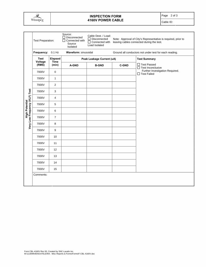
Form CBL-4160V Rev 00, Created by SNC-Lavalin Inc. M:\113099\4ENG\47ELE\RA - Misc Reports & Forms\Forms\F-CBL-4160V.doc
Test Preparation:
Source: Disconnected Connected with
Source Isolated
Cable Dest. / Load: Disconnected Connected with
Load Isolated
Note: Approval of City’s Representative is required, prior to leaving cables connected during the test.
Frequency: 0.1 Hz Waveform: sinusoidal Ground all conductors not under test for each reading.
Peak Leakage Current (uA) Test Summary Test Voltage (RMS)
Elapsed Time (min) A-GND B-GND C-GND
7000V 0
7000V 1
7000V 2
7000V 3
7000V 4
7000V 5
7000V 6
7000V 7
7000V 8
7000V 9
7000V 10
7000V 11
7000V 12
7000V 13
7000V 14
7000V 15
Test Passed Test Inconclusive
Further Investigation Required. Test Failed
Hig
h Po
tent
ial
Very
Low
Fre
quen
cy (V
LF) T
est
Comments:
Page 3 of 3
INSPECTION FORM
4160V POWER CABLE Cable ID:
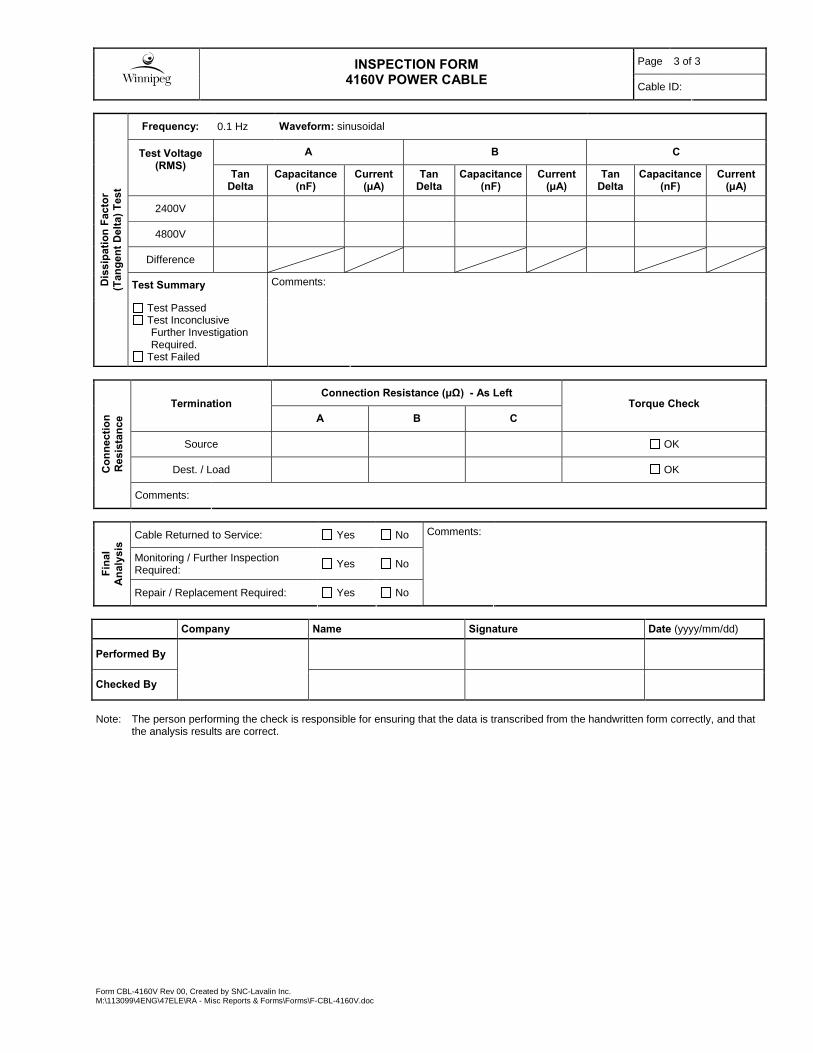
Form CBL-4160V Rev 00, Created by SNC-Lavalin Inc. M:\113099\4ENG\47ELE\RA - Misc Reports & Forms\Forms\F-CBL-4160V.doc
Frequency: 0.1 Hz Waveform: sinusoidal
A B C Test Voltage (RMS)
Tan Delta
Capacitance (nF)
Current (µA)
Tan Delta
Capacitance (nF)
Current (µA)
Tan Delta
Capacitance (nF)
Current (µA)
2400V
4800V
Difference
Test Summary Dis
sipa
tion
Fact
or
(Tan
gent
Del
ta) T
est
Test Passed Test Inconclusive
Further Investigation Required.
Test Failed
Comments:
Connection Resistance (µΩ) - As Left Termination
A B C Torque Check
Source OK
Dest. / Load OK Con
nect
ion
Res
ista
nce
Comments:
Cable Returned to Service: Yes No
Monitoring / Further Inspection Required: Yes No
Fina
l A
naly
sis
Repair / Replacement Required: Yes No
Comments:
Company Name Signature Date (yyyy/mm/dd)
Performed By
Checked By
Note: The person performing the check is responsible for ensuring that the data is transcribed from the handwritten form correctly, and that
the analysis results are correct.

Form CBL-LV Rev 00, Created by SNC-Lavalin Inc. M:\113099\4ENG\47ELE\RA - Misc Reports & Forms\Forms\F-CBL-LV.doc
Page 1 of 1
INSPECTION FORM
POWER CABLE < 1000V Cable ID:
Facility: Project Name: Pr
ojec
t
Area : Bid Opportunity:
Source: Dest. / Load:
Manufacturer: Type: Conductor: Copper Aluminum
No. of Conductors: Size: AWG
MCM Length: m Measured Jacket Markings
Previous Data TDR
Rated Voltage: V Operating Voltage: V Date Installed: C
able
Dat
a
Installation: Cable Tray Strapped
EMT Steel Conduit
Alum. Conduit PVC Conduit
Direct Buried Underground Duct Other:
Physical Damage on Exposed Ends: Yes No Cable Identification Tag Installed: Yes No
Visual Signs of Overheating: Yes No Cable Supported Appropriately: Yes No
Visu
al
Insp
ectio
n
Bend Radius Acceptable: Yes No Comments:
Test Preparation:
Source: Disconnected Connected with Source Isolated
Cable Dest. / Load: Disconnected Connected with Load Isolated
Note: Approval of City’s Representative is required, prior to leaving cables connected during the test.
Cable Temperature: °C Temperature Correction Factor for 20°C: Ground all conductors not under test for each reading.
Insulation Resistance (MΩ) Test Voltage
A-GND B-GND C-GND N-GND
Reading V
Corrected to 20oC
Test Summary
Test Passed Test Inconclusive
Further Investigation Required. Test Failed
Utilize 1000VDC Test Voltage for 600V rated cables, 500VDC for cables rated <= 300V.
Insu
latio
n R
esis
tanc
e Te
st
Comments:
Note: Torque check required for all cables. Connection Resistance Test required for cables 4/0 AWG or larger.
Connection Resistance (µΩ) - As Left Termination
A B C N Torque Check
Source OK
Dest. / Load OK
Con
nect
ion
Res
ista
nce
Comments:
Cable Returned to Service: Yes No
Monitoring / Further Inspection Required: Yes No
Fina
l A
naly
sis
Repair / Replacement Required: Yes No
Comments:
Company Name Signature Date (yyyy/mm/dd)
Performed By
Checked By

Form F-PNL-LV Rev 00, Created by SNC-Lavalin Inc. L:\40ENG\Clients\City of Winnipeg\Electrical\Forms\F-EMERG-LTG.doc
INSPECTION FORM
EMERGENCY LIGHTING
Page 1 of 1
ID:
Pro
ject
Facility: Project Name:
Area : Bid Opportunity:
Bat
tery
Un
it
Dat
a
Location: Fed From: Circuit #:
Manufacturer: Model: Serial No:
Input Voltage: V AC Input Current: A Output Voltage: V DC Wattage: W
Qty of Internal Lamps: Internal Lamp Wattage: W Type of Internal Lamps:
Rem
ote
F
ixtu
res
Quantity: Manufacturer: Model:
Input Voltage: V DC Input Current: A Qty of Lamps per Fixture:
Lamp Wattage: W Type of Lamps: Wire Size: AWG
Vis
ual
In
spec
tio
n /
Cle
anin
g
Identification Tag Installed: Yes No Lamps Properly Aimed: Yes No
Visual signs of Moisture: Yes No Connections: Good Acceptable Poor
Cleanliness (As Found): Good Acceptable Poor Ground Connection: Good Acceptable Poor
Comments:
Bat
tery
Tes
tin
g Equipment Temperature: °C Test Summary
Test Passed Test Inconclusive Further Investigation Required. Test Failed
Test Results
Stated Design Time (From Drawings): Min
Time Until Lamps Turn Off: Min
Comments:
Fin
al
An
alys
is Returned to Service: Yes No Comments:
Monitoring / Inspection Required: Yes No
Repair / Replacement Required: Yes No
Company Name Signature Date (yyyy/mm/dd)
Performed By
Checked By
Note: The person performing the check is responsible for ensuring that the data is transcribed from the handwritten form correctly, and that
the analysis results are correct.
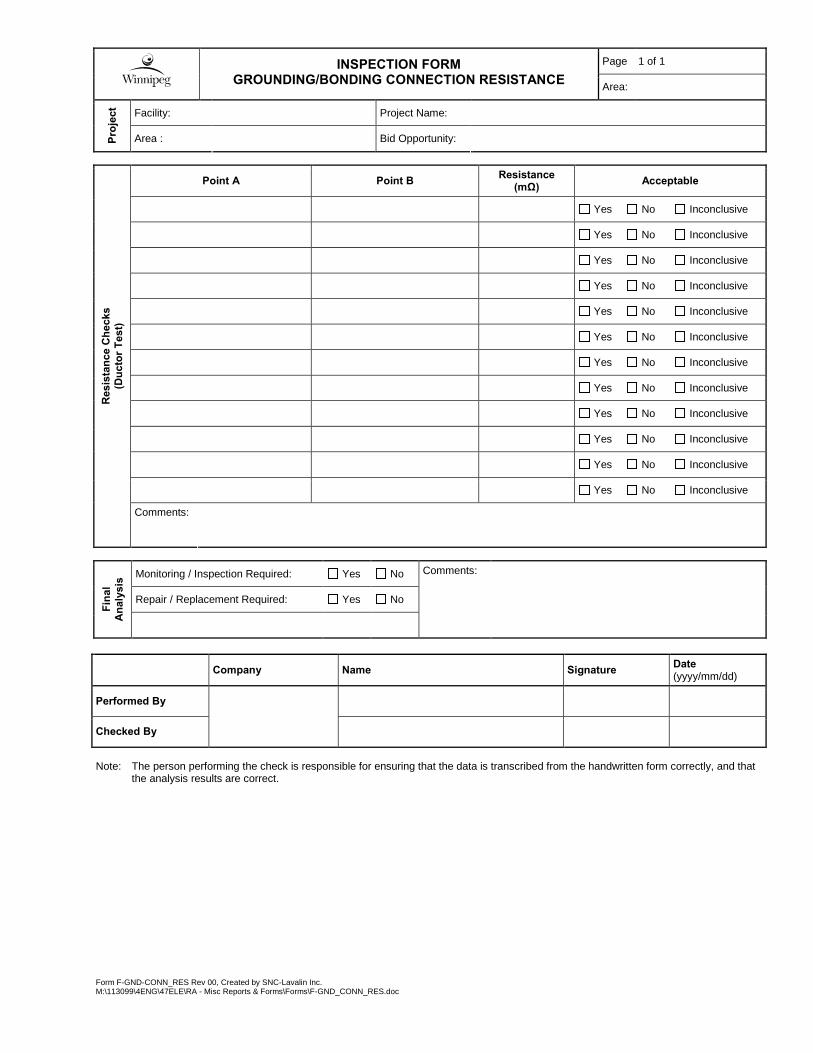
Form F-GND-CONN_RES Rev 00, Created by SNC-Lavalin Inc. M:\113099\4ENG\47ELE\RA - Misc Reports & Forms\Forms\F-GND_CONN_RES.doc
Page 1 of 1
INSPECTION FORM
GROUNDING/BONDING CONNECTION RESISTANCE Area:
Facility: Project Name: Pr
ojec
t
Area : Bid Opportunity:
Point A Point B Resistance (mΩ) Acceptable
Yes No Inconclusive
Yes No Inconclusive
Yes No Inconclusive
Yes No Inconclusive
Yes No Inconclusive
Yes No Inconclusive
Yes No Inconclusive
Yes No Inconclusive
Yes No Inconclusive
Yes No Inconclusive
Yes No Inconclusive
Yes No Inconclusive
Res
ista
nce
Che
cks
(D
ucto
r Tes
t)
Comments:
Monitoring / Inspection Required: Yes No
Repair / Replacement Required: Yes No
Fina
l A
naly
sis
Comments:
Company Name Signature Date (yyyy/mm/dd)
Performed By
Checked By
Note: The person performing the check is responsible for ensuring that the data is transcribed from the handwritten form correctly, and that
the analysis results are correct.
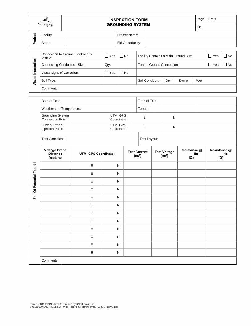
Form F-GROUNDING Rev 00, Created by SNC-Lavalin Inc. M:\113099\4ENG\47ELE\RA - Misc Reports & Forms\Forms\F-GROUNDING.doc
Page 1 of 3
INSPECTION FORM
GROUNDING SYSTEM ID:
Facility: Project Name: Pr
ojec
t
Area : Bid Opportunity:
Connection to Ground Electrode is Visible: Yes No Facility Contains a Main Ground Bus: Yes No
Connecting Conductor: Size: Qty: Torque Ground Connections: Yes No
Visual signs of Corrosion: Yes No
Soil Type: Soil Condition: Dry Damp Wet
Visu
al In
spec
tion
Comments:
Date of Test: Time of Test:
Weather and Temperature: Terrain:
Grounding System Connection Point: UTM GPS
Coordinate: E N
Current Probe Injection Point: UTM GPS
Coordinate: E N
Test Conditions: Test Layout:
Voltage Probe Distance (meters)
UTM GPS Coordinate: Test Current (mA)
Test Voltage (mV)
Resistance @ Hz
(Ω)
Resistance @ Hz
(Ω)
E N
E N
E N
E N
E N
E N
E N
E N
E N
E N
E N
E N
Fall
Of P
oten
tial T
est #1
Comments:
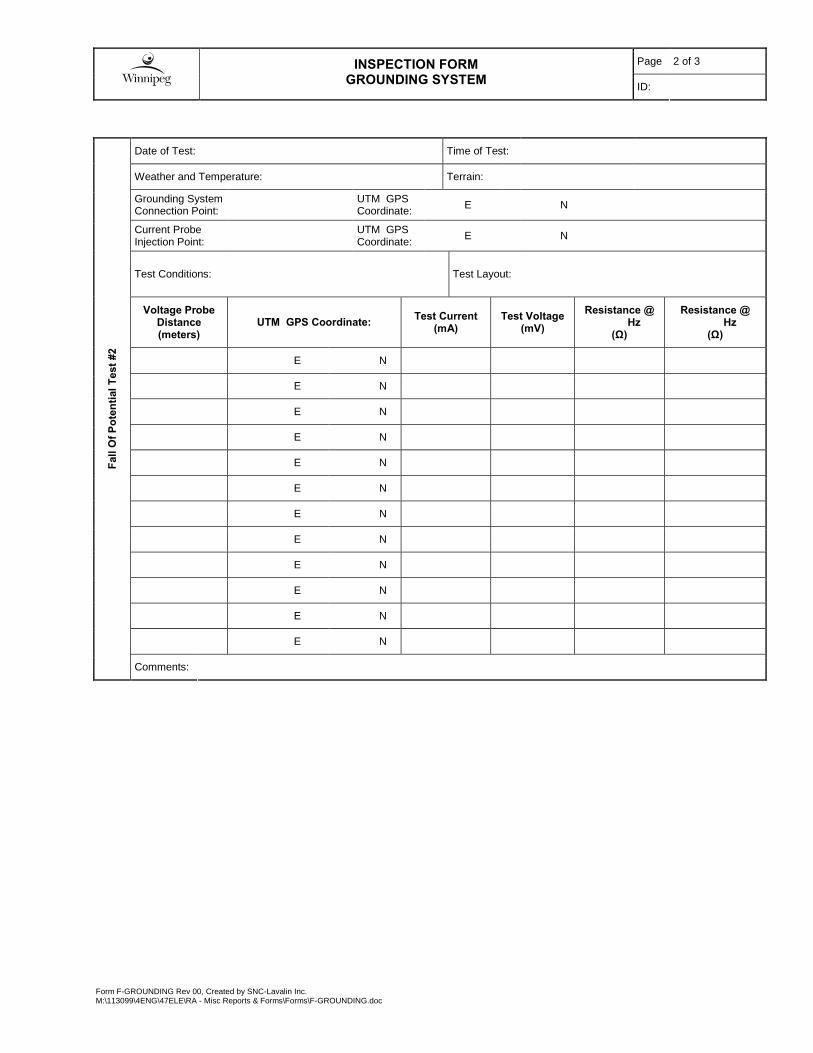
Page 2 of 3
INSPECTION FORM
GROUNDING SYSTEM ID:
Form F-GROUNDING Rev 00, Created by SNC-Lavalin Inc. M:\113099\4ENG\47ELE\RA - Misc Reports & Forms\Forms\F-GROUNDING.doc
Date of Test: Time of Test:
Weather and Temperature: Terrain:
Grounding System Connection Point: UTM GPS
Coordinate: E N
Current Probe Injection Point: UTM GPS
Coordinate: E N
Test Conditions: Test Layout:
Voltage Probe Distance (meters)
UTM GPS Coordinate: Test Current (mA)
Test Voltage (mV)
Resistance @ Hz
(Ω)
Resistance @ Hz
(Ω)
E N
E N
E N
E N
E N
E N
E N
E N
E N
E N
E N
E N
Fall
Of P
oten
tial T
est #
2
Comments:

Page 3 of 3
INSPECTION FORM
GROUNDING SYSTEM ID:
Form F-GROUNDING Rev 00, Created by SNC-Lavalin Inc. M:\113099\4ENG\47ELE\RA - Misc Reports & Forms\Forms\F-GROUNDING.doc
Test Summary Point A Point B Resistance
(mΩ)
Facility Ground Electrode Main Ground Bus
Facility Ground Electrode 4160V Switchgear GND Bus
Facility Ground Electrode System Neutral
Facility Ground Electrode 600V Switchgear GND Bus
Facility Ground Electrode MCC : GND Bus
Facility Ground Electrode MCC : GND Bus
Facility Ground Electrode Other :
Facility Ground Electrode Other :
Facility Ground Electrode Other :
Test Passed Test Inconclusive
Further Investigation Required. Test Failed
Res
ista
nce
Che
cks
(D
ucto
r Tes
t)
Comments:
Monitoring / Inspection Required: Yes No
Repair / Replacement Required: Yes No
Fina
l A
naly
sis
Comments:
Company Name Signature Date (yyyy/mm/dd)
Performed By
Checked By
Note: The person performing the check is responsible for ensuring that the data is transcribed from the handwritten form correctly, and that
the analysis results are correct.
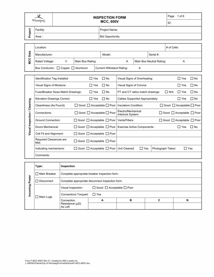
Form F-MCC-600V Rev 01, Created by SNC-Lavalin Inc. L:\40ENG\Clients\City of Winnipeg\Forms\Electrical\F-MCC-600V.doc
INSPECTION FORM
MCC, 600V
Page 1 of 6
ID:
Pro
ject
Facility: Project Name:
Area : Bid Opportunity:
MC
C D
ata
Location: # of Cells:
Manufacturer: Model: Serial #:
Rated Voltage: V Main Bus Rating: A Main Bus Neutral Rating: A
Bus Conductor: Copper Aluminum Current Withstand Rating: A
Vis
ual
Ins
pec
tio
n /
Cle
an
ing
Identification Tag Installed: Yes No Visual Signs of Overheating: Yes No
Visual Signs of Moisture: Yes No Visual Signs of Corona: Yes No
Fuse/Breaker Sizes Match Drawings: Yes No PT and CT ratios match drawings: N/A Yes No
Elevation Drawings Correct: Yes No Cables Supported Appropriately: Yes No
Cleanliness (As Found): Good Acceptable Poor Insulators Condition: Good Acceptable Poor
Connections: Good Acceptable PoorElectro/Mechanical Interlock System:
Good Acceptable Poor
Ground Connection: Good Acceptable Poor Vents/Filters: Good Acceptable Poor
Doors Mechanical: Good Acceptable Poor Exercise Active Components: Yes No
Cell Fit and Alignment: Good Acceptable Poor
Required Clearances are Met:
Good Acceptable Poor
Indicating mechanisms: Good Acceptable Poor Unit Cleaned: Yes Photograph Taken: Yes
Comments:
Inco
min
g P
ow
er
Type: Inspection
Main Breaker Complete appropriate breaker inspection form.
Disconnect Complete appropriate disconnect inspection form.
Main Lugs
Visual Inspection: Good Acceptable Poor
Connections Torqued: Yes
Connection Resistance (μΩ) As Left
A B C N
INSPECTION FORM
MCC, 600V
Page 2 of 6
ID:
Form F-MCC-600V Rev 01, Created by SNC-Lavalin Inc. L:\40ENG\Clients\City of Winnipeg\Forms\Electrical\F-MCC-600V.doc
In
sula
tio
n R
esis
tan
ce T
est
(Bu
sw
ork
)
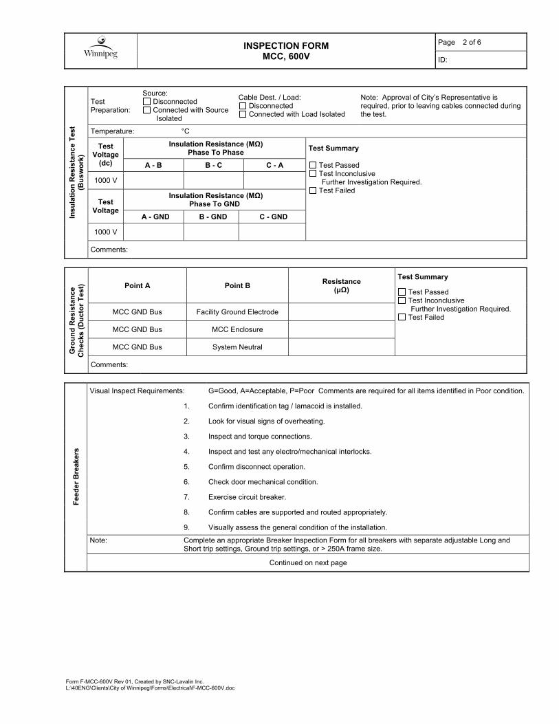
Test Preparation:
Source: Disconnected Connected with Source
Isolated
Cable Dest. / Load: Disconnected Connected with Load Isolated
Note: Approval of City’s Representative is required, prior to leaving cables connected during the test.
Temperature: °C
Test Voltage
(dc)
Insulation Resistance (MΩ) Phase To Phase
Test Summary
A - B B - C C - A Test Passed Test Inconclusive
Further Investigation Required. Test Failed
1000 V
Test Voltage
Insulation Resistance (MΩ) Phase To GND
A - GND B - GND C - GND
1000 V
Comments:
Gro
un
d R
esis
tan
ce
Ch
ecks
(D
uct
or
Tes
t)
Point A Point B Resistance
(μΩ)
Test Summary
Test Passed Test Inconclusive
Further Investigation Required. Test Failed
MCC GND Bus Facility Ground Electrode
MCC GND Bus MCC Enclosure
MCC GND Bus System Neutral
Comments:
Fee
der
Bre
aker
s
Visual Inspect Requirements: G=Good, A=Acceptable, P=Poor Comments are required for all items identified in Poor condition.
1. Confirm identification tag / lamacoid is installed.
2. Look for visual signs of overheating.
3. Inspect and torque connections.
4. Inspect and test any electro/mechanical interlocks.
5. Confirm disconnect operation.
6. Check door mechanical condition.
7. Exercise circuit breaker.
8. Confirm cables are supported and routed appropriately.
9. Visually assess the general condition of the installation.
Note: Complete an appropriate Breaker Inspection Form for all breakers with separate adjustable Long and Short trip settings, Ground trip settings, or > 250A frame size.
Continued on next page

INSPECTION FORM
MCC, 600V
Page 3 of 6
ID:
Form F-MCC-600V Rev 01, Created by SNC-Lavalin Inc. L:\40ENG\Clients\City of Winnipeg\Forms\Electrical\F-MCC-600V.doc
F
eed
er B
reak
ers
Continued from previous page
ID Loc./Cell
Fra
me
Rat
ing
(A
)
Tri
p R
ati
ng
(A
)
Manuf. Model Trip Unit
Type Inst Setting
Vis
ual
In
spec
tio
n
Cle
ane
d
Comments
General Comments:

INSPECTION FORM
MCC, 600V
Page 4 of 6
ID:
Form F-MCC-600V Rev 01, Created by SNC-Lavalin Inc. L:\40ENG\Clients\City of Winnipeg\Forms\Electrical\F-MCC-600V.doc
M
oto
r S
tart
ers
/ C
on
tact
ors
Overcurrent Protection Type: B=Breaker (Thermal Magnetic), M=Motor Circuit Protector, F=Fuse
Overload Protection Type: T=Thermal, SS=Solid State, I=Intelligent
Visual Inspect Requirements: G=Good, A=Acceptable, P=Poor Comments are required for all items identified in Poor condition.
1. Confirm identification tag / lamacoid is installed.
2. Look for visual signs of overheating.
3. Inspect and torque connections.
4. Inspect and test any electro/mechanical interlocks.
5. Confirm disconnect operation.
6. Check door mechanical condition.
7. Exercise circuit breaker.
8. Confirm cables are supported and routed appropriately.
9. Visually assess the general condition of the installation.
Note: Complete a Motor Starter Inspection Form for all Motor Starters Size 4 or larger, with VFDs, or with Soft Starters.
Mo
tor
Sta
rter
s /
Co
nta
cto
rs
ID Loc./ Cell
Overcurrent Protection Contactor Overload
Vis
ual
Ins
p.
Cle
ane
d Comments
Typ
e
Rat
ing
(A
)
Manuf. Model Size /
Rating Typ
e
Model
General Comments:

INSPECTION FORM
MCC, 600V
Page 5 of 6
ID:
Form F-MCC-600V Rev 01, Created by SNC-Lavalin Inc. L:\40ENG\Clients\City of Winnipeg\Forms\Electrical\F-MCC-600V.doc
M
oto
r S
tart
ers
ID Loc./ Cell
Overcurrent Protection Contactor Overload
Vis
ual
Ins
p.
Cle
ane
d Comments
Typ
e
Rat
ing
(A
)
Manuf. Model Size /
Rating Typ
e
Model
General Comments:
INSPECTION FORM
MCC, 600V
Page 6 of 6
ID:
Form F-MCC-600V Rev 01, Created by SNC-Lavalin Inc. L:\40ENG\Clients\City of Winnipeg\Forms\Electrical\F-MCC-600V.doc
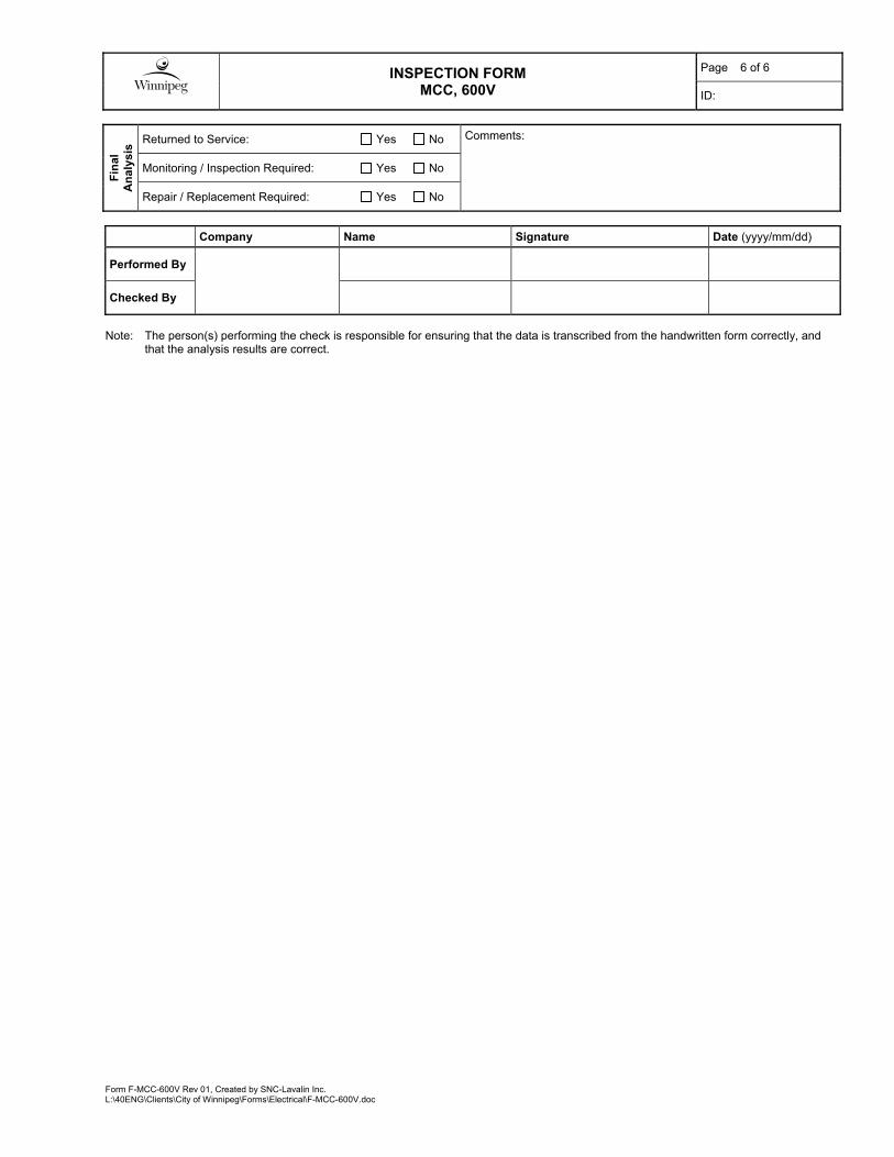
Fin
al
An
alys
is Returned to Service: Yes No Comments:
Monitoring / Inspection Required: Yes No
Repair / Replacement Required: Yes No
Company Name Signature Date (yyyy/mm/dd)
Performed By
Checked By
Note: The person(s) performing the check is responsible for ensuring that the data is transcribed from the handwritten form correctly, and
that the analysis results are correct.

Form MS-FVNR-600V Rev 02, Created by SNC-Lavalin Inc. L:\40ENG\Clients\City of Winnipeg\Forms\Electrical\F-MS-FVNR-600V.doc
INSPECTION FORM
MOTOR STARTER, FVNR, 600V
Page 1 of 2
ID:
Pro
ject
Facility: Project Name:
Area : Bid Opportunity:
Sta
rter
Dat
a
Load: Starter Location: Cell #:
Manufacturer: Type: Serial #:
Size: Rated Voltage: V Current Rating: A Control Voltage: V
Circuit Protection:
Fused Disc. Rating: A Fuse Size: A Fuse Mfg.
Model:
Breaker MCP
Rating: A Inst. Setting:
A Manufacturer:
Model:
Overload Protection:
Thermal Electronic Intelligent
Class:
10 20 30 Unknown
Setting / Rating: A
Manufacturer:
Model:
Control Power Transformer: Size: VA Sec. Voltage: V Primary Fuse: A Secondary Fuse: A
Current Transformers: Phases:
A B C
None Ratio: Ground Fault CT:
Present Not Present
Ratio:
Mo
tor
Dat
a ID: Size: kW / HP Voltage: V
Full Load Amps: A Service Factor: Other:
Vis
ual
Insp
ecti
on
/ C
lean
ing
Starter Identification Tag Installed: Yes No Visual Signs of Overheating: Yes No
Cleanliness (As Found): Good Acceptable Poor Support Insulators: Good Acceptable Poor
Connections Good Acceptable Poor Electro/Mechanical Interlock: N/A Good Acceptable Poor
Ground Connection: Good Acceptable Poor Contactor Condition: Good Acceptable Poor
Door Mechanical Good Acceptable Poor Contact Alignment: Good Acceptable Poor
Verify O/L element is correctly sized for the load: Yes No Exercise Circuit Breaker/MCP/Disconnect Yes
Cables Supported Appropriately: Yes No Unit Cleaned: Yes Photograph Taken: Yes
Comments:
Co
nta
ct/P
ole
M
easu
rem
ents
Test A B C Test Summary
Test Passed Test Inconclusive
Further Investigation Required. Test Failed
Contact Resistance (µΩ)
Disconnect / Breaker / MCP Resistance (µΩ)
Fuse Resistance (µΩ)
Comments:
INSPECTION FORM
MOTOR STARTER, FVNR, 600V
Page 2 of 2
ID:
Form MS-FVNR-600V Rev 02, Created by SNC-Lavalin Inc. L:\40ENG\Clients\City of Winnipeg\Forms\Electrical\F-MS-FVNR-600V.doc
Insu
lati
on
Res
ista
nce
Tes
t
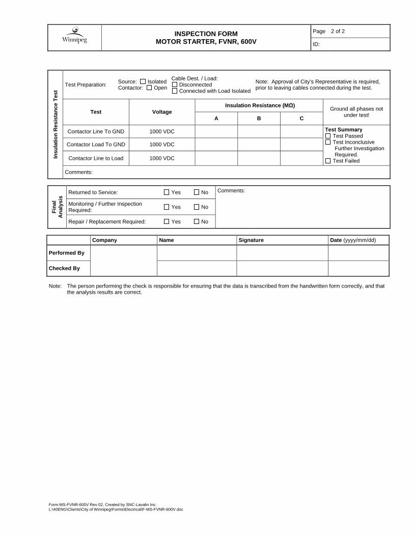
Test Preparation: Source: Isolated Contactor: Open
Cable Dest. / Load: Disconnected Connected with Load Isolated
Note: Approval of City’s Representative is required, prior to leaving cables connected during the test.
Test Voltage Insulation Resistance (MΩ)
Ground all phases not under test!
A B C
Contactor Line To GND 1000 VDC Test Summary Test Passed Test Inconclusive
Further Investigation Required.
Test Failed
Contactor Load To GND 1000 VDC
Contactor Line to Load 1000 VDC
Comments:
Fin
al
An
alys
is Returned to Service: Yes No Comments:
Monitoring / Further Inspection Required: Yes No
Repair / Replacement Required: Yes No
Company Name Signature Date (yyyy/mm/dd)
Performed By
Checked By
Note: The person performing the check is responsible for ensuring that the data is transcribed from the handwritten form correctly, and that
the analysis results are correct.

Form F-MTR-LV Rev 00, Created by SNC-Lavalin Inc. M:\113099\4ENG\47ELE\RA - Misc Reports & Forms\Forms\F-MTR-LV.doc
Page: 1 of 2
INSPECTION FORM
AC MOTOR, LOW VOLTAGE ID:
Facility: Project Name:
Proj
ect
Area : Bid Opportunity:
Size: kW / HP Voltage: V R.P.M:
Manufacturer: Model: Serial Number:
Frame Type: Service Factor: Other:
Mot
or D
ata
Cooling: Air Fan # Cooling Fans: Winding
Material:
Motor Identification Tag Installed: Yes No Visual Signs of Overheating: Yes No
Connections: Good Acceptable Poor Air Baffles: Good Acceptable Poor
Paint: Good Acceptable Poor Filter Media: N/A Good Acceptable Poor
Cooling Fans: N/A Good Acceptable Poor Fan Controls: N/A Good Acceptable Poor
Anchorage/Alignment: Good Acceptable Poor
Ground Connection: Good Acceptable Poor
Mechanical/Electrical Noise During Operation: Yes No Lubrication Required: Yes No Vi
sual
Insp
ectio
n / C
lean
ing
Cleanliness (As Found): Good Acceptable Poor Unit Cleaned: Yes Photograph Taken: Yes
Resistance (MΩ)
Stator Winding Test
Voltage (Vdc)
Winding Temperature (°C) 30 Sec 1 min. 10 min. (a)
Dielectric Absorption
Ratio
Polarization Index (a)
- - 500
40
- - 500
40
- - 500
40
Notes:
(a) Testing to 10 minutes and calculation of Polarization Index is only required for motors > 150 kW (200 HP)
Win
ding
Insu
latio
n R
esis
tanc
e
Test Summary Test Passed Test Inconclusive. Further Investigation Required. Test Failed
Resistance (µΩ) Test Summary
A - B B – C A - C
Test Passed Test Inconclusive
Further Investigation Required. Test Failed W
indi
ng
Res
ista
nce
Comments:

Page: 2 of 2
INSPECTION FORM
AC MOTOR, LOW VOLTAGE ID:
Form F-MTR-LV Rev 00, Created by SNC-Lavalin Inc. M:\113099\4ENG\47ELE\RA - Misc Reports & Forms\Forms\F-MTR-LV.doc
Not Applicable Resistance (MΩ)
Bearing Test Voltage (Vdc)
Bearing Temperature (°C) 1 min. Corrected to 40°C
500
500
Bea
ring
Insu
latio
n R
esis
tanc
e
Test Summary Test Passed Test Inconclusive. Further Investigation Required. Test Failed
Not Applicable
Actual Winding Temperature: °C Actual Bearing Temperature °C
RTD Resistance (Ω)
Calculated Temperature
(°C) RTD Resistance
(Ω) Calculated
Temperature (°C)
RTD
Res
ista
nce
Test Summary Test Passed Test Inconclusive. Further Investigation Required. Test Failed Note: Test connection resistance of bolted connections. Report on cable inspection sheet.
Returned to Service: Yes No
Monitoring / Further Inspection Required: Yes No
Fina
l A
naly
sis
Repair / Replacement Required: Yes No
Comments:
Company Name Signature Date (yyyy/mm/dd)
Performed By
Checked By
Note: The person(s) performing the check is responsible for ensuring that the data is transcribed from the handwritten form correctly, and that the analysis results are correct.

Form F-RELAY-VM-SSAC-WVM Rev 00, Created by SNC-Lavalin Inc. L:\40ENG\Clients\City of Winnipeg\Electrical\Forms\F-RELAY-VM-SSAC-WVM.doc
INSPECTION FORM
VOLTAGE MONITOR, SSAC-WVM
Page 1 of 2
ID:
Pro
ject
Facility: Project Name:
Area : Bid Opportunity:
Rel
ay D
ata
Location: Cell #:
Manufacturer: Model:
Type: Serial No.:
Comments:
Vis
ual
Insp
ecti
on
A B C A B C
Moisture/Rust: Relay Cleaned:
Over-heating: Screws Tightened:
Cover/Case:
Legend: A-Acceptable C-Corrected N-Needs Repair NA-Not Applicable
Comments:
Rel
ay S
etti
ng
s
Parameter Setting (As Found)
Setting (As Left)
Line Voltage
Unbalance
Trip Delay
Restart Delay
Mode Switch
Bas
ic V
olt
age
Tes
ts
Desired Phase Voltage Actual Voltage Relay State Time to Change OK
A B C A B C
600 600 600
0 600 600
600 600 600
600 0 600
600 600 600
600 600 0
600 600 600
Comments:

INSPECTION FORM
VOLTAGE MONITOR, SSAC-WVM
Page 2 of 2
ID:
Form F-RELAY-VM-SSAC-WVM Rev 00, Created by SNC-Lavalin Inc. L:\40ENG\Clients\City of Winnipeg\Electrical\Forms\F-RELAY-VM-SSAC-WVM.doc
Fin
al
An
alys
is Returned to Service: Yes No Comments:
Monitoring / Further Inspection Required: Yes No
Repair / Replacement Required: Yes No
Company Name Signature Date (yyyy/mm/dd)
Performed By
Checked By
Note: The person(s) performing the check is responsible for ensuring that the data is transcribed from the handwritten form correctly, and that the analysis results are correct.
Form F-XFMR-DRY-LV Rev 02, Created by SNC-Lavalin Inc. L:\40ENG\Clients\City of Winnipeg\Electrical\Forms\F-XFMR-DRY-LV.doc
Page 1 of 2
INSPECTION FORM
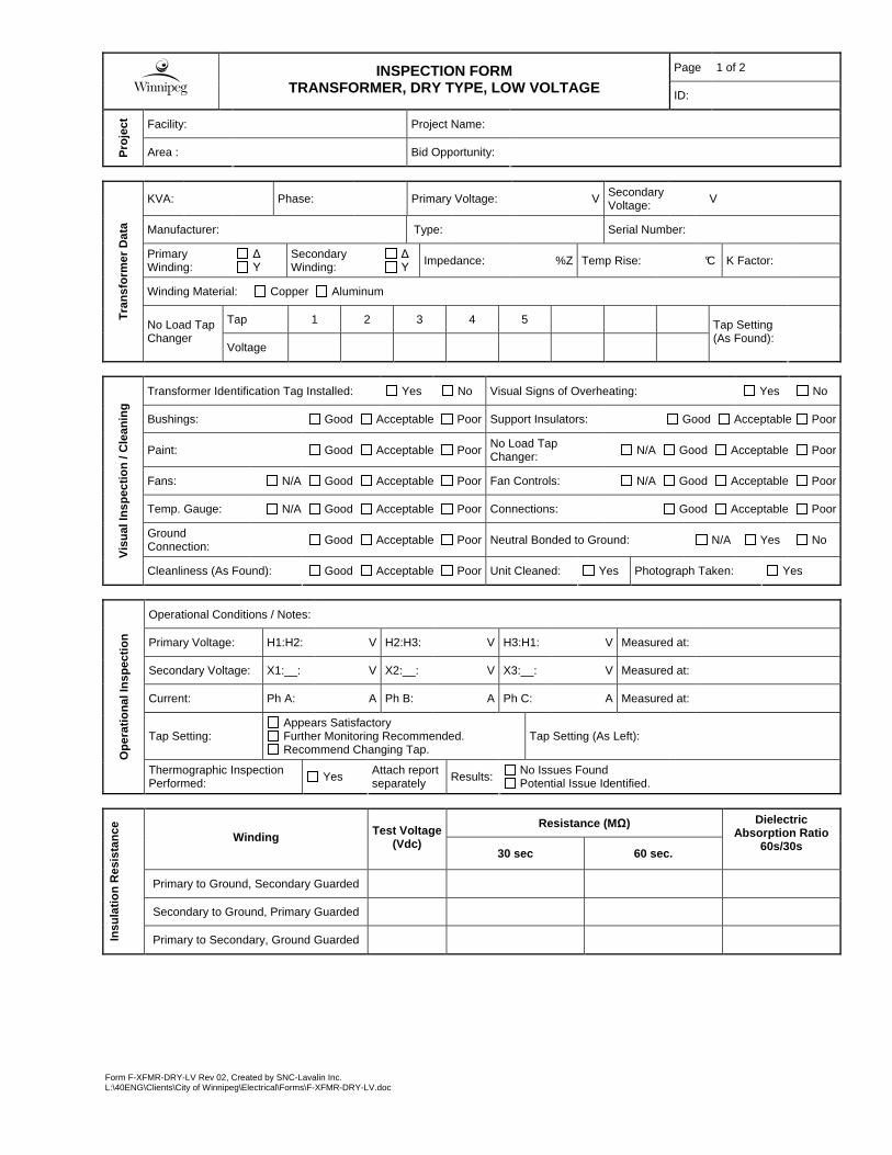
TRANSFORMER, DRY TYPE, LOW VOLTAGE ID:
Facility: Project Name: P
roje
ct
Area : Bid Opportunity:
KVA: Phase: Primary Voltage: V Secondary Voltage:
V
Manufacturer: Type: Serial Number:
Primary Winding:
∆ Υ
Secondary Winding:
∆ Υ Impedance: %Z Temp Rise: °C K Factor:
Winding Material: Copper Aluminum
Tap 1 2 3 4 5 Tra
nsf
orm
er D
ata
No Load Tap Changer
Voltage
Tap Setting (As Found):
Transformer Identification Tag Installed: Yes No Visual Signs of Overheating: Yes No
Bushings: Good Acceptable Poor Support Insulators: Good Acceptable Poor
Paint: Good Acceptable Poor No Load Tap Changer: N/A Good Acceptable Poor
Fans: N/A Good Acceptable Poor Fan Controls: N/A Good Acceptable Poor
Temp. Gauge: N/A Good Acceptable Poor Connections: Good Acceptable Poor
Ground Connection: Good Acceptable Poor Neutral Bonded to Ground: N/A Yes No
Vis
ual
Insp
ecti
on
/ C
lean
ing
Cleanliness (As Found): Good Acceptable Poor Unit Cleaned: Yes Photograph Taken: Yes
Operational Conditions / Notes:
Primary Voltage: H1:H2: V H2:H3: V H3:H1: V Measured at:
Secondary Voltage: X1:__: V X2:__: V X3:__: V Measured at:
Current: Ph A: A Ph B: A Ph C: A Measured at:
Tap Setting: Appears Satisfactory Further Monitoring Recommended. Recommend Changing Tap.
Tap Setting (As Left):
Op
erat
ion
al In
spec
tio
n
Thermographic Inspection Performed: Yes
Attach report separately Results:
No Issues Found Potential Issue Identified.
Resistance (MΩ) Winding Test Voltage
(Vdc) 30 sec 60 sec.
Dielectric Absorption Ratio
60s/30s
Primary to Ground, Secondary Guarded
Secondary to Ground, Primary Guarded
Insu
lati
on
Res
ista
nce
Primary to Secondary, Ground Guarded
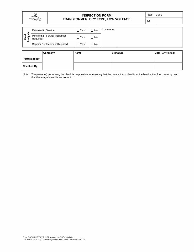
Page 2 of 2
INSPECTION FORM
TRANSFORMER, DRY TYPE, LOW VOLTAGE ID:
Form F-XFMR-DRY-LV Rev 02, Created by SNC-Lavalin Inc. L:\40ENG\Clients\City of Winnipeg\Electrical\Forms\F-XFMR-DRY-LV.doc
Returned to Service: Yes No
Monitoring / Further Inspection Required:
Yes No
Fin
al
An
alys
is
Repair / Replacement Required: Yes No
Comments:
Company Name Signature Date (yyyy/mm/dd)
Performed By
Checked By
Note: The person(s) performing the check is responsible for ensuring that the data is transcribed from the handwritten form correctly, and
that the analysis results are correct.
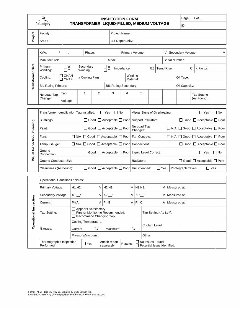
Form F-XFMR-LIQ-MV Rev 01, Created by SNC-Lavalin Inc. L:\40ENG\Clients\City of Winnipeg\Electrical\Forms\F-XFMR-LIQ-MV.doc
Page: 1 of 3
INSPECTION FORM
TRANSFORMER, LIQUID-FILLED, MEDIUM VOLTAGE ID:
Facility: Project Name: P
roje
ct
Area : Bid Opportunity:
KVA: / / Phase: Primary Voltage: V Secondary Voltage: V
Manufacturer: Model: Serial Number:
Primary Winding:
∆ Υ
Secondary Winding:
∆ Υ Impedance: %Z Temp Rise: °C K Factor:
Cooling: ONAN ONAF # Cooling Fans:
Winding Material: Oil Type:
BIL Rating Primary: BIL Rating Secondary: Oil Capacity:
Tap 1 2 3 4 5
Tra
nsf
orm
er D
ata
No Load Tap Changer
Voltage
Tap Setting (As Found):
Transformer Identification Tag Installed: Yes No Visual Signs of Overheating: Yes No
Bushings: Good Acceptable Poor Support Insulators: Good Acceptable Poor
Paint: Good Acceptable Poor No Load Tap Changer: N/A Good Acceptable Poor
Fans: N/A Good Acceptable Poor Fan Controls: N/A Good Acceptable Poor
Temp. Gauge: N/A Good Acceptable Poor Connections: Good Acceptable Poor
Ground Connection: Good Acceptable Poor Liquid Level Correct: Yes No
Ground Conductor Size: Radiators: Good Acceptable Poor Vis
ual
Insp
ecti
on
/ C
lean
ing
Cleanliness (As Found): Good Acceptable Poor Unit Cleaned: Yes Photograph Taken: Yes
Operational Conditions / Notes:
Primary Voltage: H1:H2: V H2:H3: V H3:H1: V Measured at:
Secondary Voltage: X1:__: V X2:__: V X3:__: V Measured at:
Current: Ph A: A Ph B: A Ph C: A Measured at:
Tap Setting: Appears Satisfactory Further Monitoring Recommended. Recommend Changing Tap.
Tap Setting (As Left):
Cooling Temperature: Current oC Maximum: oC
Coolant Level: Gauges:
Pressure/Vacuum: Other:
Op
erat
ion
al In
spec
tio
n
Thermographic Inspection Performed: Yes
Attach report separately Results:
No Issues Found Potential Issue Identified.
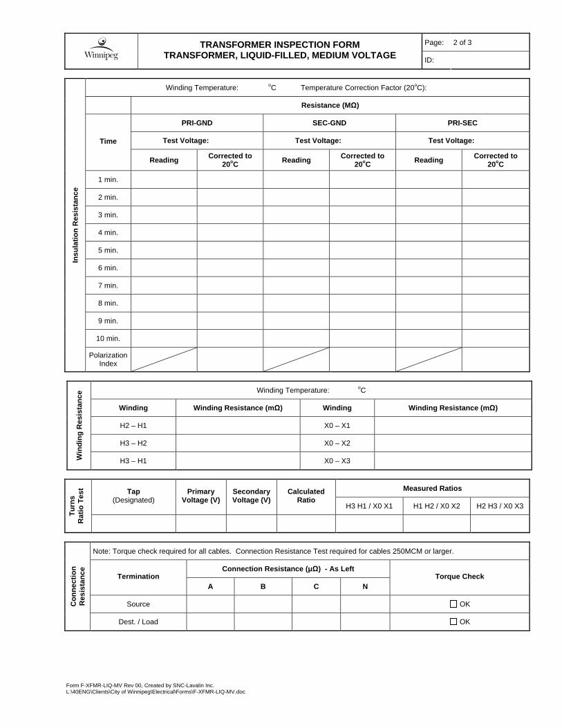
Page: 2 of 3
TRANSFORMER INSPECTION FORM
TRANSFORMER, LIQUID-FILLED, MEDIUM VOLTAGE ID:
Form F-XFMR-LIQ-MV Rev 00, Created by SNC-Lavalin Inc. L:\40ENG\Clients\City of Winnipeg\Electrical\Forms\F-XFMR-LIQ-MV.doc
Winding Temperature: oC
Winding Winding Resistance (mΩ) Winding Winding Resistance (mΩ)
H2 – H1 X0 – X1
H3 – H2 X0 – X2
Win
din
g R
esis
tan
ce
H3 – H1 X0 – X3
Measured Ratios Tap (Designated)
Primary Voltage (V)
Secondary Voltage (V)
Calculated Ratio
H3 H1 / X0 X1 H1 H2 / X0 X2 H2 H3 / X0 X3
Tu
rns
Rat
io T
est
Note: Torque check required for all cables. Connection Resistance Test required for cables 250MCM or larger.
Connection Resistance (µΩ) - As Left Termination
A B C N Torque Check
Source OK Co
nn
ecti
on
R
esis
tan
ce
Dest. / Load OK
Winding Temperature: oC Temperature Correction Factor (20oC):
Resistance (MΩ)
PRI-GND SEC-GND PRI-SEC
Test Voltage: Test Voltage: Test Voltage: Time
Reading Corrected to 20oC Reading Corrected to
20oC Reading Corrected to 20oC
1 min.
2 min.
3 min.
4 min.
5 min.
6 min.
7 min.
8 min.
9 min.
10 min.
Insu
lati
on
Res
ista
nce
Polarization Index

Page: 3 of 3
TRANSFORMER INSPECTION FORM
TRANSFORMER, LIQUID-FILLED, MEDIUM VOLTAGE ID:
Form F-XFMR-LIQ-MV Rev 00, Created by SNC-Lavalin Inc. L:\40ENG\Clients\City of Winnipeg\Electrical\Forms\F-XFMR-LIQ-MV.doc
Dielectric Breakdown Voltage:
Colour:
Acid Neutralization Number: Visual Condition:
Specific Gravity: Power Factor or Dissipation Factor:
Insu
lati
ng
Liq
uid
T
ests
Dissolved Gas Analysis:
Other:
Returned to Service: Yes No
Monitoring / Further Inspection Required:
Yes No
Fin
al
An
alys
is
Repair / Replacement Required: Yes No
Comments:
Company Name Signature Date (yyyy/mm/dd)
Performed By
Checked By
Note: The person performing the check is responsible for ensuring that the data is transcribed from the handwritten form correctly, and that
the analysis results are correct.
Related Documents