Electrochimica Acta 106 (2013) 483–493 Contents lists available at SciVerse ScienceDirect Electrochimica Acta jo u r n al hom ep age: www.elsevier.com/locate/electacta Insights about the irreversible capacity of LiNi 0.5 Mn 1.5 O 4 cathode materials in lithium batteries Sergio Brutti a,∗∗ , Giorgia Greco b , Priscilla Reale b , Stefania Panero b,∗ a Dipartimento di Scienze, Università della Basilicata, Via Nazario Sauro 85, 85100 Potenza, Italy b Dipartimento di Chimica, Sapienza Università di Roma, P.le Aldo Moro 5, 00185 Roma, Italy a r t i c l e i n f o Article history: Received 3 October 2012 Received in revised form 16 May 2013 Accepted 22 May 2013 Available online 3 June 2013 Keywords: Li-ion batteries Cathodes Irreversible capacity Electrolyte decomposition a b s t r a c t The accumulation of irreversible capacity in the first cycle and upon cycling has been studied for LiNi 0.5 Mn 1.5 O 4 -based cathodes (LNMO), bare and coated with ZnO. Materials have been synthesized at 800 ◦ C and characterized by X-ray diffraction and transmission electron microscopy (TEM). The precip- itation of a continuous ZnO film on the surface of LNMO has been highlighted by TEM. Galvanostatic cycling at room temperature and at 60 ◦ C, linear sweep voltammetry (LSV), impedance spectroscopy and TEM techniques have been used to investigate the materials and the irreversible capacity accumulation upon cycling. Our study confirms that continuous parasitic processes occur upon cycling beyond the first charge/discharge. Anodic LSV test shows that side oxidation processes start on the surface of a LNMO electrode at potential slightly above the Ni 2+ /Ni 4+ redox couple. At the end of charge an uniform and continuous thin film (3–4 nm) forms of on the bare LNMO. This film likely modifies upon cycling and it is apparently unable to passivate the LNMO surface preventing further decompositions. On the contrary the material coated with ZnO shows rough surfaces without large morphological alteration upon charge and cycling. The ZnO coating confirms its ability to mitigate the irreversible charge consumption. © 2013 Elsevier Ltd. All rights reserved. 1. Introduction The development of new cathode materials for Li-ion cells is one of the key issues to develop batteries with improved performances, suitable for automotive applications. LiCoO 2 is the typical used cathode material in commercial lithium-ion batteries. However lithium cobaltites suffer economic and environmental drawbacks: intense research efforts are spent worldwide to find substitutes. Among these the LiN 0.5 Mn 1.5 O 4 spinel (LNMO) has been inten- sively studied in the last decade mainly because of its high working voltage (>4.7 V) and improved environmental compatibility [1]. LNMO exploits the redox couple Ni 2+ /Ni 4+ to provide one Li atom per formula unit and a theoretical specific capacity of 146.5 mAh g -1 . Its oxidation occurs in a stable voltage plateau around 4.75–4.85 V vs. Li + /Li. In the first electrochemical Li de-insertion/insertion LNMO suf- fers irreversible capacity losses: in the following cycles, at room temperature, it shows high reversibility and stable cycling perform- ances, from low to high current rates. On the contrary above 50 ◦ C, ∗ Corresponding author. Tel.: +39 06 49913703; fax: +39 06 491769. ∗∗ Corresponding author. E-mail addresses: [email protected], [email protected] (S. Brutti), [email protected] (S. Panero). LNMO suffers a quick deterioration of the performances due to the growth of parasitic reactions with the electrolyte [2]. The occurrence of electrolyte decomposition upon cycling is unavoidable due to the high working voltage of LNMO, i.e. 4.75–4.85 V vs. Li + /Li, at the upper limit of the thermodynamic stability window of any organic carbonate currently adopted in Li-cells. As a consequence LNMO supplies more than one nomi- nal lithium per formula unit (e.g. [3]) at low rates, going beyond the theoretical capacity. This results in a poor coulombic efficiency in the first complete cycle [4]. These drawbacks limit the adoption of LNMO in Li-cells and require developing specific strategies to suppress the parasitic reactions. The investigation of the capacity fading in LNMO electrodes has been addressed recently by various authors. In a series of papers Aurbach and co-workers [5–7] observe that LNMO nanoparticles are much more reactive towards LiPF 6 -based electrolytes com- pared to microsized LNMO materials (see also Ref. [8]). Apparently the chemistry of the interaction of LNMO with electrolytes involves a nucleophilic reaction between the ethylene carbonate molecule from the electrolyte and the negatively charge oxygen on the sur- face of LNMO particles. Such reaction occurs in parallel with the oxidation of LNMO and may lead to the precipitation of organic carbonates, alkoxydes and polycarbonates. The formation of these carbonaceous by-products has been confirmed by Yang and co- workers that observed the formation of poly-ethylencarbonate on 0013-4686/$ – see front matter © 2013 Elsevier Ltd. All rights reserved. http://dx.doi.org/10.1016/j.electacta.2013.05.111

Welcome message from author
This document is posted to help you gain knowledge. Please leave a comment to let me know what you think about it! Share it to your friends and learn new things together.
Transcript

Electrochimica Acta 106 (2013) 483– 493
Contents lists available at SciVerse ScienceDirect
Electrochimica Acta
jo u r n al hom ep age: www.elsev ier .com/ locate /e lec tac ta
Insights about the irreversible capacity of LiNi0.5Mn1.5O4 cathodematerials in lithium batteries
Sergio Brutti a,∗∗, Giorgia Grecob, Priscilla Realeb, Stefania Panerob,∗
a Dipartimento di Scienze, Università della Basilicata, Via Nazario Sauro 85, 85100 Potenza, Italyb Dipartimento di Chimica, Sapienza Università di Roma, P.le Aldo Moro 5, 00185 Roma, Italy
a r t i c l e i n f o
Article history:
Received 3 October 2012Received in revised form 16 May 2013Accepted 22 May 2013Available online 3 June 2013
Keywords:
Li-ion batteriesCathodesIrreversible capacityElectrolyte decomposition
a b s t r a c t
The accumulation of irreversible capacity in the first cycle and upon cycling has been studied forLiNi0.5Mn1.5O4-based cathodes (LNMO), bare and coated with ZnO. Materials have been synthesized at800 ◦C and characterized by X-ray diffraction and transmission electron microscopy (TEM). The precip-itation of a continuous ZnO film on the surface of LNMO has been highlighted by TEM. Galvanostaticcycling at room temperature and at 60 ◦C, linear sweep voltammetry (LSV), impedance spectroscopy andTEM techniques have been used to investigate the materials and the irreversible capacity accumulationupon cycling.
Our study confirms that continuous parasitic processes occur upon cycling beyond the firstcharge/discharge. Anodic LSV test shows that side oxidation processes start on the surface of a LNMOelectrode at potential slightly above the Ni2+/Ni4+ redox couple. At the end of charge an uniform andcontinuous thin film (3–4 nm) forms of on the bare LNMO. This film likely modifies upon cycling and itis apparently unable to passivate the LNMO surface preventing further decompositions. On the contrarythe material coated with ZnO shows rough surfaces without large morphological alteration upon chargeand cycling. The ZnO coating confirms its ability to mitigate the irreversible charge consumption.
© 2013 Elsevier Ltd. All rights reserved.
1. Introduction
The development of new cathode materials for Li-ion cells is oneof the key issues to develop batteries with improved performances,suitable for automotive applications. LiCoO2 is the typical usedcathode material in commercial lithium-ion batteries. Howeverlithium cobaltites suffer economic and environmental drawbacks:intense research efforts are spent worldwide to find substitutes.Among these the LiN0.5Mn1.5O4 spinel (LNMO) has been inten-sively studied in the last decade mainly because of its high workingvoltage (>4.7 V) and improved environmental compatibility [1].
LNMO exploits the redox couple Ni2+/Ni4+ to provide oneLi atom per formula unit and a theoretical specific capacity of146.5 mAh g−1. Its oxidation occurs in a stable voltage plateauaround 4.75–4.85 V vs. Li+/Li.
In the first electrochemical Li de-insertion/insertion LNMO suf-fers irreversible capacity losses: in the following cycles, at roomtemperature, it shows high reversibility and stable cycling perform-ances, from low to high current rates. On the contrary above 50 ◦C,
∗ Corresponding author. Tel.: +39 06 49913703; fax: +39 06 491769.∗∗ Corresponding author.
E-mail addresses: [email protected], [email protected] (S. Brutti),[email protected] (S. Panero).
LNMO suffers a quick deterioration of the performances due to thegrowth of parasitic reactions with the electrolyte [2].
The occurrence of electrolyte decomposition upon cyclingis unavoidable due to the high working voltage of LNMO, i.e.4.75–4.85 V vs. Li+/Li, at the upper limit of the thermodynamicstability window of any organic carbonate currently adopted inLi-cells. As a consequence LNMO supplies more than one nomi-nal lithium per formula unit (e.g. [3]) at low rates, going beyondthe theoretical capacity. This results in a poor coulombic efficiencyin the first complete cycle [4]. These drawbacks limit the adoptionof LNMO in Li-cells and require developing specific strategies tosuppress the parasitic reactions.
The investigation of the capacity fading in LNMO electrodes hasbeen addressed recently by various authors. In a series of papersAurbach and co-workers [5–7] observe that LNMO nanoparticlesare much more reactive towards LiPF6-based electrolytes com-pared to microsized LNMO materials (see also Ref. [8]). Apparentlythe chemistry of the interaction of LNMO with electrolytes involvesa nucleophilic reaction between the ethylene carbonate moleculefrom the electrolyte and the negatively charge oxygen on the sur-face of LNMO particles. Such reaction occurs in parallel with theoxidation of LNMO and may lead to the precipitation of organiccarbonates, alkoxydes and polycarbonates. The formation of thesecarbonaceous by-products has been confirmed by Yang and co-workers that observed the formation of poly-ethylencarbonate on
0013-4686/$ – see front matter © 2013 Elsevier Ltd. All rights reserved.
http://dx.doi.org/10.1016/j.electacta.2013.05.111
484 S. Brutti et al. / Electrochimica Acta 106 (2013) 483– 493
LNMO after prolonged potentiostatic holds at 5.0 and 5.3 V [9]. Alsothe precipitation of fluorine-containing species, i.e. LiF, LixMOyFz
and MnF2, on the LNMO surface has been observed or speculated[5,10–12]. In particular the smooth capacity fading in prolongedcycling at room temperature seems to be related to accumulationof LiF and the concomitant thickening of the surface films [10,13].These parasitic reactions are likely promoted by the traces of HFunavoidably present in any electrolyte. In fact HF acts as scaveng-ing agent that leads to the dissolution of Mn2+ ions from the LNMOsurface through the following process [7,14]:
4LiNi0.5Mn1.5O4 + 8HF → �-MnO2 + MnF2 + NiF2
+ 4LiF + 4H2O + 2Ni0.5Mn1.5O4 (R1)
At temperatures above 50 ◦C all these parasitic processes areenhanced [14] thus leading to the quick deterioration of the per-formances of LNMO in lithium cells.
The deposition of a ZnO coating apparently limits the Mn2+ lossby reducing the amount of free HF in the electrolyte, and stabi-lizes the cycling above room temperature, as discussed by Sun andco-workers [15,16] and recently re-examined by Arrebola et al. [4].Moreover, the ZnO coating also mitigates the deposition on the sur-face of the LNMO of carbonaceous species due to the decompositionof the electrolyte at high voltages [15,16]. Aurbach et al. [7] studiedin detail the effect of coating LNMO with ZnO and MgO nanopar-ticles. Apparently these coatings protect the LNMO surface fromthe acidic molecules in the standard electrolyte solutions based onLiPF6. This effect reduces the dissolution of Mn and Ni ions into theelectrolyte thus mitigating the charge losses. Furthermore, Aurbachet al. [7] infer that ZnO and MgO can also easily convert to the cor-responding insoluble difluorides by direct reaction with the HF, byreleasing water molecules (MO + 2HF = MF2 + H2O), thus reducingthe amount of free H+ in the electrolyte. This effect can limit theabove-mentioned H+-catalyzed reaction (R1). On the other handas ZnO and MgO coating materials are highly hygroscopic, watercan hydrate their surfaces: such hydration can de-activate watermolecules and can inhibit the further formation of HF through thereaction
LiPF6 + H2O = POF3 + 2HF
In this paper insights about the irreversible capacity loss in thefirst cycle for LNMO are reported in comparison to the same LNMOmaterial coated with ZnO. The goal is to investigate the decompo-sition of the electrolyte on the surface of LNMO at high voltagein standard galvanostatic experiments at room temperature, byelectrochemical tests and transmission electron microscopy.
2. Experimental details
LNMO has been synthesized by co-precipitation from an aque-ous solution of the Mn2+, Ni2+ and Li+ nitrates [17]. Stoichiometricamounts of the corresponding nitrates have been dissolved in fewmillilitres of water and the solution was kept at 50 ◦C under vigor-ous stirring until complete H2O evaporation. The mixed nitrate hasbeen transferred in an alumina crucible and fired in air at 800 ◦Cfor 12 h. The resulting powder has been hand grinded and newlyannealed at 850 ◦C for 12 h followed by controlled cooling to roomtemperature at 1 ◦C/min.
The ZnO coating has been obtained by suspending the LNMOpowder in few millilitres of water by vigorous stirring. A stoichio-metric amount of Zn2+ acetate (corresponding to a final ratio of1.5 wt% of ZnO) has been added to the aqueous suspension andthe resulting solution has been heated and kept under stirringat 40–50 ◦C for few hours, until complete H2O evaporation. The
resulting composite powder has been annealed in air at 500 ◦C for30 min with a heating/cooling rate of 1 ◦C/min [18].
The materials have been characterized by X-ray diffraction(XRD), scanning electron microscopy (SEM) with energy dispersivespectroscopy (EDS), transmission electron microscopy (TEM) andelemental analysis by inductively coupled plasma atomic absorp-tion (ICP-AA).
The XRD experiments have been carried out using a Rigaku X-ray Ultima+ diffractometer equipped with a Cu K� source and agraphite monocromator for the diffracted beam. SEM images havebeen obtained by an Oxford Instruments LEO 1450VP. The EDSanalyses have been performed using an INCA X-sight Oxford Instru-ments apparatus. The TEM micrographies have been obtained by aJEOL JEM 2011 HR TEM instrument. The Fourier Transform Infrared(FTIR) spectroscopy tests have been carried out by a Bruker AlphaFTIR in transmission using KBr pellets: the pellets preparation andFTIR experiments have been carried out in an Ar-filled glove box.
The electrochemical tests have been carried out on casted elec-trodes. The cathode films have been deposited on an aluminium foilby doctor-blading a slurry composed of 80% of the active material(AM), 10% of poly-vinyl-difluoride (PVDF 6020 Solvay Solef) and10% of SuperP carbon. The mass loading over the aluminium foil isapproximately 2.5 mg cm−2. The electrochemical performances ofthe active materials have been recorded on cells assembled using aworking electrode prepared as described above, combined with alithium counter electrode. The adopted electrolyte is a 1 M LiPF6
solution in an ethylene carbonate–dimethyl carbonate mixture,EC:DMC 1:1 (LP30, Merck Battery Grade), soaked on a WhatmanTM
separator. Cells have been assembled in an MBraun-type dry boxwith moisture and oxygen levels below 1 ppm. The galvanostaticcyclings (CG) have been performed in two electrodes cell. The CGtests have been carried out at various specific currents, normalizedfor the active materials weight, within a 3.5–5.0 V limits unless dif-ferently indicated, using a Maccor Series 4000 Battery Test System.The materials for ex situ TEM analysis have been obtained by de-assembling the cells and washing the electrodes in DMC and THFin glove box under Ar. Impedance spectroscopy experiments havebeen carried out on three electrodes cells with a lithium referenceelectrode, using the Solartron Analytical Modulab apparatus. AllEIS experiments have been carried out on electrodes with identicalmass loads per square centimetre and thicknesses in a frequencyrange 100 kHz–10 mHz with a voltage signal of 5 mV.
3. Results and discussion
3.1. Materials characterization and electrochemical
performances in lithium cells
As expected the pristine and the ZnO coated LNMO materialsshow identical XRD patterns (see Fig. 1 of Ref. [18]): apparentlydiffraction is unable to detect the precipitation of zinc oxide atsuch small ZnO concentrations, as already pointed out by Sun et al.[2], Arrebola et al. [4] and us in a previous publication [18]. Onthe contrary electron microscopy is able to detect the ZnO coat-ing: Fig. 1a and b shows HRTEM (high resolution TEM) images ofbare and coated LNMO. The corresponding three-dimensional (3D)reconstructions obtained by the ImageJ software are presented inFig. 1c and d [19,20]. A fast Fourier Transform (FFT) analysis of theHRTEM of the uncoated material is shown as an inset in Fig. 1a. Thereciprocal lattice shown in the inset of Fig. 1a can be indexed withan fcc structure with a cell constant of 8.0(3) A corresponding tothe LNMO spinel lattice [17]: it is in agreement within the errorswith the 8.19(4) A lattice parameter derived from the XRD pattern.The linear greyscale profile calculated on the outer layer of parti-cle shown in the HRTEM image of the coated sample is shown theinset of Fig. 1b. It is possible to estimate a length periodicity in the

S. Brutti et al. / Electrochimica Acta 106 (2013) 483– 493 485
Fig. 1. (a) HRTEM image of the LNMO spinel pristine material. In the inset the fast Fourier Transform (FFT) of the HRTEM image shows lattice reflections (the cross lines in themain 1 figure are only indication marks to highlight the area where the FFT has been calculated); (b) HRTEM image of the LNMO spinel ZnO coated material, cross-sectionalline profile taken from the ZnO coating. (c) and (d) Three-dimensional reconstructions from the HRTEM images.
greyscale oscillations of ∼4.8 A, a value that is in excellent agree-ment with to the lattice parameter of the ZnO zincoblende cubicstructure [21]. Turning to the 3D images (Fig. 1c and d), there is anevident alteration of the surface of the coated particles comparedto the bare LNMO. TEM images suggest the formation of a contin-uous rough film, constituted by ZnO, precipitated on the surface ofthe LNMO particles with mean thickness of 3–5 nm.
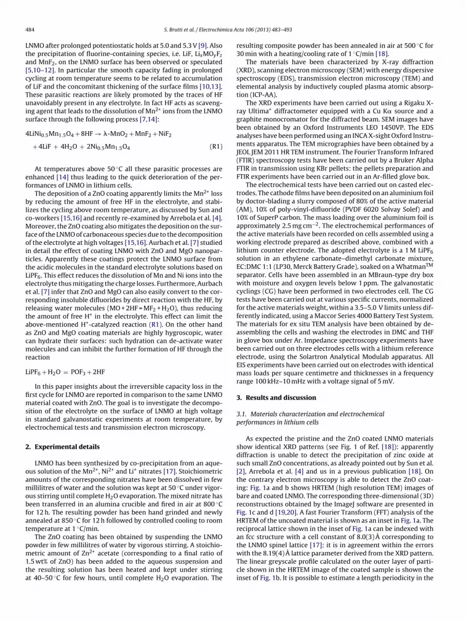
The voltage profiles of the uncoated and coated materials inlithium cells are shown in Fig. 2. The two curves show very similarshapes. Three main effects are induced by the ZnO coating: (i) a 15%reduction of the charge capacity (148 vs. 127 mAh g−1 for the bareand the coated materials, respectively); (ii) a 30% decrease of theirreversible capacity loss in the first Li+ de-insertion/insertion cycle(35 vs. 24 mAh g−1 for the bare and the coated materials, respec-tively); (iii) a slight increase in the potential hysteresis betweencharge and discharge (70 mV vs. 100 mV for the bare and thecoated materials, respectively). These experimental evidences canbe explained by considering the role played by the ZnO coating asHF trap [7,15,16]. In fact the decrease of the unavoidable traces of
free HF in the electrolyte is expected to mitigate the LNMO sur-face scavenging thus limiting the occurrence of further parasiticreactions. It is to be noted that the increased voltage hysteresisbetween charge and discharge is likely due to the presence of theZnO layer. In fact it probably negatively affects the electron mobil-ity within the electrode and the lithium ion diffusion across theelectrolyte/electrode interface.
The two bare and coated materials show comparable perform-ances in GC at room temperature as shown in Fig. 3. The coatedmaterial shows a smaller cumulative irreversible capacity loss uponcycling (i.e. the sum over cycles of the difference between thecharge and discharge capacity) only partially counterbalanced by aslight decrease of the reversible specific capacity.
At 60 ◦C the bare material suffers a diverging cumulativeirreversible capacity loss upon cycling and a continuous fadingof the cycled specific capacities. After 80–90 cycles the perform-ances at 60 ◦C of the bare LNMO electrodes dramatically drop(result checked in duplicate) similarly to what observed by Sunand co-workers [2,15,16]. As expected the parasitic reactions occur

486 S. Brutti et al. / Electrochimica Acta 106 (2013) 483– 493
Fig. 2. Galvanostatic voltage profiles (first cycle) of the LNMO material bare andcoated with ZnO.
faster at higher temperatures thus leading to a steeper trend in thecumulative irreversible capacity. The bare LNMO material suffersa cumulative irreversible capacity loss larger than 100 mAh g−1 atcycle 13 at room temperature to be compared to cycle 8 for the GCat 60 ◦C. On the contrary the ZnO coated material shows a remark-able stability upon cycling with minor losses in the specific capacityand a smaller cumulative irreversible capacity loss in comparisonwith the bare material. In fact the coated material reaches a cumu-lative irreversible capacity loss that exceed 100 mAh g−1 at cycle 36(room temperature) and at cycle 32 (60 ◦C).
On passing, it is interesting to observe that the galvanostaticcycling at 55 ◦C of the uncoated LNMO synthesized by Sun et al. [15]shows an immediate dramatic loss in the specific capacity after thethird cycle, with a capacity retention after 50 cycles of about 25%.On the contrary Arrebola et al. [4] report stable performances forthe bare material at 50 ◦C. However the comparison is biased notonly by the small differences in the temperatures but mainly by thedifferent anodic voltage cut-offs, i.e. 5.3 V and 5 V for Sun et al. andArrebola et al., respectively, to be compared to the 5 V cut-off usedin our tests. In fact an anodic polarization beyond 5 V, well abovethe working potential of the LNMO material, is expected to stronglyenhance any parasitic reactions on the surface of the electrode andto facilitate its failure.
In summary, at temperatures above 25 ◦C, parasitic reactionsoccur continuously upon cycling on the surface of LNMO-basedmaterials. The growth of a ZnO film on the surface of the activematerial is capable to mitigate such capacity losses at room tem-perature as well as at 60 ◦C.
3.2. Impedance spectroscopy tests upon cycling
The EIS spectra of the charged (at 5 V vs. Li+/Li) and dischargeselectrodes (at 3.5 V vs. Li+/Li) are presented in Fig. 4 for both thebare and the coated materials.
The impedance of the electrodes in their discharged state isalways larger than in the charged state in agreement with Amatucciet al. [23] and Davidson et al. [10]. This phenomenon is generallyascribed to the higher resistivity of manganite-based electrodes intheir lithiated state compared to the de-lithiated one [22,23] dueto the smaller ion mobility and electronic conductivity.
The equivalent circuit for this class of material electrodes (i.e.LiMn2O4 manganites) has been discussed and proposed by Aurbachand co-workers [22]. It consists of the resistance of the solution Rs,in series with a block consisting of the resistance of the electrode
surface, Rf, in parallel with is capacity, Cf. This section is in serieswith another similar block consisting of the charge-transfer resis-tance. Rct, in parallel with the double layer capacitance, Cdl. A finalWarburg impedance at low frequency, W, is found in series to allthese elements and is likely related to the solid state Li+ ion dif-fusion [10,22]. The final equivalent circuit is summarized by thefollowing string: Rs(RfCf)(RctCdl)W.
The first (RfCf) block fits the first part of the EIS spectra, i.e. thehigh to medium frequency semicircle, and can be attributed to themigration of Li+ ions from the electrolyte through the surface filmsof the active material particles. In this view this section of the EISspectra gives direct insights about the precipitation and growth ofa passivation film, its properties and changes upon cycling.
The EIS spectra shown in Fig. 4 for both charged and dischargestates show a first semi-circle in the high-medium frequency rangeand a second semi-circle, very large and not completed, in themedium-low frequency range. The first semi-circles are fitted bythe (RfCf) block of the above discussed equivalent circuit. The Cf
capacitance values (Cf ∼ 10−6–10−5 F) confirm in all cases that thesesemi-circles are related to a surface layer formed on the activematerial. This surface layer is probably a passivation film consti-tuted by the electrolyte decomposition products precipitated onthe LNMO particles and in the case of the coated material abovethe ZnO coating. The plots of the fitted passivation film resistances,Rf, are shown in Fig. 3.
It is important to underline that, in all cases, the passivationfilm resistances (Rf) are for both the charged and the dischargedstates larger in the case of the bare LNMO electrode compared tothe coated one.
The bare material shows for the charged states a rapid increasein the passivation film resistance in the firsts 3 cycles followed bya smooth increasing trend. The coated material shows in the firstcycle a passivation film resistance very similar to the bare LNMO:however in the following cycles it shows only a slightly positiveslope without abrupt changes.
In the discharged states the passivation film resistance for thebare material shows a constant increasing trend upon cycling. Onthe contrary the passivation film resistance of the coated materialoscillates upon cycling without showing a monotonic increasingtrend.
The EIS results agree with the trends of the cumulativeirreversible capacity in CGs at room temperature. In the case ofthe bare LNMO material the increase of the passivation film resis-tance upon cycling occurs in parallel with the accumulation ofirreversible capacity. Apparently these losses correspond to theprecipitation of by-products on the surface of the LNMO material,thus leading to a probable thickening of the passivation film or itsdensification.
Turning to the coated material, apparently the EIS results high-light a smaller resistance of the passivation film as well as a smallerincreasing trend upon cycling in comparison with the bare LNMO.The impedance data confirm the ability of the ZnO coating to limitthe accumulation of insoluble decomposition by-products on theelectrode surface.
3.3. Analysis of the irreversible capacity loss in the first
electrochemical Li de-insertion/insertion cycle: linear sweep
voltammetry and ex situ TEM analysis
Linear sweep voltammetry (LSV) tests have been carried out forthe bare and coated materials from the OCV (open circuit voltage)to 6 V vs. Li+/Li. The results are shown in Fig. 5.
Both materials show a current peak centred at about 4.8 V vs.Li+/Li due to the lithium removal and the concomitant oxidation ofthe Ni2+ ions in the LNMO lattice. The peak for the coated materialis broader and asymmetric compared to the bare LNMO.

S. Brutti et al. / Electrochimica Acta 106 (2013) 483– 493 487
Room temperature 60°C
0 10 20 30 40 50 60 70 80 90 1000
50
100
150
200
Room temperature
Cycle
Sp
ecif
ic c
ap
aci
ty /
mA
h g
-1
Li/LP30/(AM 80% carbon 10% binder 10%)
OCV-5V-3V i=50mAg-1
LNMO
LNMO coated with 1.5 wt% ZnO
0 10 20 30 40 50 60 70 80 90 1000
50
100
150
200
60 C degrees
Cycle
gy
pp
Li/LP30/(AM 80% carbon 10% binder 10%)
OCV-5V-3V i=50mAg-1
LNMO
LNMO coated with 1.5 wt% ZnO
0 20 40 60 80 1000
50
100
150
200
250
300
350
400
Room temperature
Cycle
ssol
ytica
pac el
bisreverri e
vital
um
uC
mA
h g
-1
Li/LP30/(AM 80% carbon 10% binder 10%)
OCV-5V-3V i=50mAg-1
LNMO
LNMO coated with 1.5 wt% ZnO
0 20 40 60 80 1000
50
100
150
200
250
300
350
400
60 C degrees
Cycle
g h
Am / ss
ol y tic
ap
ac cif icep
S
Li/LP30/(AM 80% carbon 10% binder 10%)
OCV-5V-3V i=50mAg-1
LNMO
LNMO coated with 1.5 wt% ZnO
Fig. 3. (a) and (b) Performances in galvanostatic tests of the bare and the ZnO coated LNMO materials at room temperature and at 60 ◦C and (c) and (d) correspondingcumulative irreversible capacity loss plots.
At about 5 V this process overlaps with another minor electroac-tive reaction in both cases. In the case of the ZnO coated material,this second anodic peak is broader: it is also shifted at higherpotential compared to the bare material, i.e. V > 4.9 V and 5 V vs.Li+/Li, for the bare and the coated LNMO, respectively. Both theseprocesses cannot be ascribed to a reversible oxidation of LNMO:more likely they are related to the oxidation of some electrolytecomponents. Such decompositions may lead to the precipitationof insoluble organic molecules (e.g. polyethers and organic carbo-nates ROCO2M) that may accumulate on the electrode surface, asreported in literature [10,13].
Above 5.5 V vs. Li+/Li in both cases massive decomposition reac-tions occur. These voltammetric peaks can be attributed to theevolution of CO2 at the cathode side, as well as the production ofmany other gaseous by-products from the oxidation of the elec-trolyte solvent molecules (CO2, CO, H2, CH4, C2H6 and C2H4) [24].
The linear sweep voltammetry tests suggest that on the sur-face of a LNMO electrode a first parasitic oxidation process startsat potential similar to the Ni2+/Ni4+ redox couple. The ZnO coat-ing is apparently able to broaden this process on a larger voltagerange and to shift upwards the peak current for this undesired reac-tion, beyond 5 V vs Li+/Li. As already mentioned this process canbe attributed to a parasitic oxidation of an electrolyte components.One can speculate that the upward shift of the peak potential above5.0 V due to the ZnO coating may result from a barrier to the electrontransfer, from the electrolyte to the electrode, due to the insulatingZnO layer.
The ex situ TEM images of the bare and coated materials chargedat 4.7 (before the working voltage) and at 5 V vs. Li+/Li (end ofcharge) are shown in Fig. 6. The bare material surface shows theprecipitation of a continuous surface film at 5.0 V as well as 4.7 Vvs. Li+/Li, well before the onset of the parasitic oxidation process

488 S. Brutti et al. / Electrochimica Acta 106 (2013) 483– 493
Charged stat es at 5 V Discharged states at 3 VU
nco
ate
d L
NM
OZ
nO
coate
d L
NM
OP
ass
ivati
on
fil
mre
sist
an
ce
Rf
0 20 40 60 80 100 120
uncoated LNMO
charged states at 5 V
30
20
10
5
1
cycle
numbe r
Zim
magin
ary
/ O
hm
0 20 40 60 80 10 0 12 0
uncoated LNMO
discharged states at 3 V
30
20
10
5
1
cycle
number
0 20 40 60 80 100 120
ZnO coated LNMO
charged states at 5 V30
20
10
5
1
cycle
number
Zim
ma
gin
ary
/ O
hm
Zreal
/ Ohm
0 20 40 60 80 100 120
ZnO coated LNMO
discharged state s at 3 V30
20
10
5
1
cycle
number
Zreal
/ Ohm
0 5 10 15 20 25 300
20
40
60
80charged stat es at 5 V
uncoated LNMO
ZnO coated LNMO
Pa
ssiv
ati
on
fil
m r
esis
tan
ce
Oh
m
Cycle number
0 5 10 15 20 25 300
20
40
60
80discharged state s at 3 V
uncoated LNMO
ZnO coated LNMO
Cycle number
Fig. 4. EIS spectra in charged and discharged states upon cycling of the bare and ZnO coated LNMO materials. Cells have been cycled at 50 mAh g−1 in the voltage range5–3.5 V vs. Li+/Li.
observed in the LSV. The thickness of the passivation film is about3–4 nm and apparently covers uniformly the surface of the LNMOlattice. The morphology of this surface film is very similar to theMnF2 layer experimentally observed by TEM by Aurbach and co-workers [7]. This surface layer is likely due to the abovementionedreaction (R1) that is activated and fed by the unavoidable HF tracesin the electrolyte [7,14]. On passing it is important to remind thatthe formation of such thin and continuous film on the surface of the
bare material does not prevent further accumulation of irreversiblecapacity losses upon cycling (see previous section). Apparently thisfilm is unable to passivate the LNMO surface.
A surface film on the LNMO particles is also observed in thecase of the ZnO coated material. It is morphologically very differ-ent from that observed on the bare LNMO: it is not uniform andit is remarkably rough. From the morphological point of view thisfilm is very similar to pristine ZnO coating (see Fig. 1). Owing to

S. Brutti et al. / Electrochimica Acta 106 (2013) 483– 493 489
Fig. 5. Anodic linear sweep voltammetry tests of the bare and the ZnO coated LNMOmaterials.
this it is very difficult to discriminate between the original ZnOcoating and the further SEI layer formed on it. The thickness of thefilm observed on the ZnO coated LNMO particles charged at 4.7 and5.0 V vs. Li+/Li ranges between 5 and 8 nm whereas the pristine ZnOcoating is about 3–5 nm thick (see Fig. 1). The apparent thickening
of the film would suggest the accumulation of limited amounts ofamorphous-like substances on the ZnO coating. However the pre-cipitation of these electrolyte decomposition by-products does notform a continuous and uniform film.
The different morphology of the two film formed on the bareand the ZnO coated LNMO may suggest a different chemical com-position. As an example, in the view of the observation by Aurbachand co-workers [7], our TEM images could suggest that the abil-ity of ZnO to capture water and to decrease the free acidity byHF in the electrolyte (see also [7]), may limit the occurrence ofthe abovementioned spontaneous reaction (R1), therefore reduc-ing the scavenging of manganese/nickel ions to form insolublefluorides.
3.4. Analysis of the irreversible capacity loss in the first
electrochemical Li de-insertion/insertion cycle: galvanostatic
charge/discharge and impedance spectroscopy tests
In order to analyze more in detail the accumulation of chargelosses upon charge/discharge we carried out a study of the evo-lution of the coulombic efficiency with the anodic voltage cut-offfor both the bare and the ZnO coated material. The results are pre-sented in Fig. 7.
The evolution of the specific capacity in charge and theirreversible capacity accumulation in the first cycle show simi-lar trends for both materials. However, the coated material shows
Fig. 6. Ex situ transmission electron micrographs of the bare and the ZnO coated LNMO materials charged at 4.7 and 5 V vs. Li+/Li.

490 S. Brutti et al. / Electrochimica Acta 106 (2013) 483– 493
Fig. 7. Performances in galvanostatic tests at various anodic cut-off potentials of the uncoated and coated LNMO materials.
improved reversibility, i.e. smaller irreversible capacity losses andlarger coulombic efficiencies, in the whole voltage cut-offs range,compared to the bare one.
It is possible to identify three voltage regions: (1) from the OCVto 4.65 V vs. Li+/Li; (2) the intermediate range between 4.65 and4.8 V vs. Li+/Li and (3) potentials above 4.8 V vs. Li+/Li. A summaryof the galvanostatic performances of the bare and coated materialsin the three voltage ranges is presented in Table 1.
1. At cell potential <4.65 V vs. Li+/Li the specific capacity in chargeis mainly due to the oxidation of the redox couple Mn3+/Mn4+.The LNMO lattice should not contain Mn3+ ions. Howeverthis undesired contamination is well known and is apparentlyunavoidable: it occurs in parallel with the precipitation of nickeloxide during the synthesis [1,18]. In this voltage range the barematerial supplies a specific capacity approximately 30% largercompared to the coated material. However this larger chargecapacity is due mainly to irreversible parasitic processes: in thisvoltage range the coulombic efficiencies for the bare material
are smaller of about 20% compared to the ZnO coated material.In both cases only limited amounts of charge are irreversiblylost in this voltage range, i.e. 10 and 7% of the overall irreversiblecapacity loss in the first GC cycle for the bare and the ZnO coatedmaterials, respectively.
2. In the voltage range between 4.65 and 4.8 V vs. Li+/Li the LNMOlattice undergoes to the Ni2+/Ni4+ oxidation process by de-intercalating two Li+ ions per Ni2+. In this voltage range thecoulombic efficiencies of the two materials are very similar. Theirreversible capacity losses between 4.65 and 4.8 V vs. Li+/Li sumthe main part of the inefficiency in the entire first cycle forboth materials. However the coated material losses are smallerin absolute value of 20% compared to the bare one. This evi-dence suggests that parasitic processes occur on the surface ofthe bare LNMO: the ZnO coating is apparently able to mitigatethese detrimental reactions.
3. The third voltage range, i.e. 4.8 < V < 5.1 V vs. Li+/Li, is abovethe working potential of the LNMO lattice. However fur-ther reversible charge is exchanged also this range, i.e. 22.1
Table 1
Specific capacity supplied in the first charge and irreversible capacity loss in function of the cut-off potential for the uncoated and the coated material.
Voltage range vs. Li+/Li Charge specific capacity (mAh g−1) Irreversible capacity loss (mAh g−1) Coulombic efficiency
Uncoated Coated Uncoated Coated Uncoated Coated
OCV < V < 4.65 10.8 7.5 3.9 1.7 0.64 0.774.65 < V < 4.8 114.2 102.5 19.1 15.2 0.83 0.854.8 < V < 5.1 37.2 29.5 15 7.1 0.49 0.70

S. Brutti et al. / Electrochimica Acta 106 (2013) 483– 493 491
Fig. 8. EIS spectra upon first charge and discharge of the uncoated and coated LNMO materials.
and 22.4 mAh g−1 for the uncoated and the coated materials,respectively. This reversible capacity is probably due to kinet-ically limited lithium removal/insertion sites. In this voltagerange the irreversible capacity suffered by the bare material
doubles that observed for the ZnO coated LNMO. As a conse-quence, the coulombic efficiency of the bare material is largelysmaller than that of the coated one. The irreversible capacityaccumulated in this voltage range sum approximately 40% and

492 S. Brutti et al. / Electrochimica Acta 106 (2013) 483– 493
30% of the total losses suffered by the bare and the coated mate-rials, respectively.
In order to study the modification of the electrolyte/electrodeinterface upon first GC cycle we carried out a detailed impedancespectroscopy experiments at various stages of charge and dis-charge.
The results of the two EIS experiments are presented in Fig. 8.Qualitatively the coated and the bare materials show a very similarevolution of the EIS spectra both upon charge and discharge.
As discussed above, the EIS spectra upon charge/dischargecan be fitted by an equivalent circuit summarized by the string:Rs(RfCf)(RctCdl)W [10,22] for both materials. Similarly to the EISspectra reported in Fig. 4 the first semi-circle can be attributed tothe formation of a surface layer whereas the second one easily isdue to the charge transfer associated with the Li extraction andinsertion from and into the LNMO lattice. The trends of the fittedpassivation film resistances are reported in Fig. 8.
On passing it is to be noted that at the end of the first chargethere is an inversion of the values of the resistances of the passiv-ation film reported in Fig. 8 compared to Fig. 4 (first cycle). Thepassivation film on the bare LNMO electrodes shows at the endof charge a resistance of 18 � (Fig. 4) or 12 � (Fig. 8) whereas theZnO coated electrodes shows 10 � (Fig. 4) and 14 � (Fig. 8). It is ouropinion that, in the view of the small and similar values of the resis-tances of the four different cells and in the view the different chargeconditions for the electrodes shown in Figs. 4 and 8, the absoluteestimates of the resistance are to be considered indistinguishable.To support this opinion, although not completely rigorous, we cal-culated the mean values of the passivation film resistance after thefirst charge for both materials. The resulting values are: 15 ± 3 and12 ± 2 � for the bare and the coated LNMO, respectively: they agreewithin the error.
The resistance of the passivation film shows slight differencesbetween the bare and coated materials: upon Li removal (charge)three regions can be identified:
• Below 4.7 V vs. Li+/Li: the resistance of the passivation filmslightly increases in the case of the bare material whereas it isstable for the coated one.
• Between 4.7 and 4.8 V vs. Li+/Li: the resistance of the passivationfilm drops of about 50% and 30% for the bare and coated materials,respectively.
• Above 4.8 V vs. Li+/Li: the resistance of the passivation filmincreases for both materials with a steeper trend in the case of thebare material. The final values of the passivation film resistanceare very similar for both materials.
Similarly upon Li insertion (discharge) three regions can be iden-tified:
• Above 4.65 V vs. Li+/Li: the resistance of the passivation film isalmost constant for both materials.
• Between 4.65 and 4.55 V vs. Li+/Li: the resistance of the passiv-ation film drastically increases of about 180 and 250% for the bareand the coated material, respectively.
• Below 4.55 vs. Li+/Li: the resistance of the passivation film is con-stant in the case of the bare material whereas it drops of about36% for the coated one. The final values of the passivation filmresistance are very similar for both materials.
The evolution of the passivation film resistance shows slightdifferences upon charge and discharge between the bare and thecoated materials. In particular in charge the bare material showsbelow 4.7 and above 4.8 V vs. Li+/Li larger increasing trends com-pared to the coated one. These growths occur in the same voltage
ranges where it suffers the largest irreversible capacity losses inthe CG tests (see Fig. 6 and Table 1). The parallel occurrence ofthese two effects suggests a possible increase of the thickness ofthe passivation film, or its densification, due to the accumulationof by-products from the parasitic oxidation of the electrolyte.
The large drops in the film resistance observed for both materi-als between 4.7 and 4.8 V are less easily understandable: possibleexplanations may involve the formation of cracks or the modifica-tion of the surface layer properties. Cracks may expose unprotectedLNMO surface directly to the electrolyte, thus (a) boosting thelithium ions mobility through the electrolyte/electrode interfaceand (b) activating further parasitic oxidations of the electrolyte.
On the other hand the reaction mechanism of LNMO is known tohave two topotactic two-phase reactions: (1) in the range Li = 1 toLi = 0.5 from cubic (a = 8.19 A) to cubic lattice (a = 8.09 A) and (2) inthe range Li = 0.5 to Li = 0 from cubic (1 = 8.09 A) to cubic (a = 7.99 A)cell [1]. The volume shrinking upon lithium removal is approxi-mately −7% and it is fully recovered upon lithium insertion. Suchmoderate volume variation is unlikely to be responsible of massivefractures on the surface layer. This speculation is apparently sup-ported by the TEM data shown in Fig. 6. The ex situ TEM picturesof the bare LNMO electrodes at the end of charge show a compactand continuous thin film on the surface of the crystal particles. Asalready mentioned this morphology reminds that observed by Aur-bach and co-workers [7]. Moreover, the morphology of this filmdoes not apparently alter upon charge (before and after the mainvoltage plateau: 4.7 and 5.0 V vs. Li+/Li, respectively).
As a consequence the abrupt variation of the resistance of thepassivation layer observed in the EIS experiments cannot be easilyrelated to the occurrence of cracks in the surface layer. More likelythe film composition and density modifies upon lithium extractionfrom the LNMO lattice improving the lithium conductivity throughthis interphase.
Turning to the coated material, the evolution of its surface filmresistance in the first cycle is qualitatively similar compared to thebare one. This experimental evidence suggests that, although themorphology and the composition of the surface films formed uponfirst charge on the bare and coated LNMO particles are different,the fundamental chemistry is similar in both cases. Apparently theZnO coating does not alter drastically the overall picture: uponcharge the ZnO coating mitigates the changes in the passivationfilm resistance whereas in discharge it favours the formation of amore resistive film at the end of the Li+ insertion.
4. Conclusions
A study of the accumulation of irreversible capacity losses inthe first cycle and upon cycling has been carried out for twoLNMO-based cathodes, one bare and one coated with ZnO. Galvano-static tests performed at room and at 60 ◦C suggest that parasiticprocesses occur continuously upon cycling on the surface of LNMO-cathodes. In fact the cumulative irreversible capacity plots show anincreasing trend even after 80 cycles. The ZnO coating confirms itsability to mitigate this effect. Impedance spectroscopy tests suggestthe formation of a passivation film on the surface of the LNMO-based electrodes with an increasing resistance upon cycling.
Anodic LSV test shows that parasitic oxidations start on the sur-face of LNMO electrodes at potential slightly above the Ni2+/Ni4+
redox couple. The ZnO coating is apparently able to broaden thisprocess on a larger voltage range and to shift upwards the onsetpotential for this undesired reaction beyond 5 V. Ex situ TEM imagesrecorded on charged electrodes highlight the precipitation of anuniform and continuous thin film (3–4 nm) on the bare LNMOparticles upon first charge. However the formation of such thinand continuous film of the surface of the bare material does not

S. Brutti et al. / Electrochimica Acta 106 (2013) 483– 493 493
prevent the accumulation of further irreversible capacity lossesupon cycling. The TEM images of the ZnO coated material showsrough surfaces without large alteration upon first charge.
The analysis of the coulombic efficiencies in the first cycle atvarious voltage cut-offs in GC tests suggest that irreversible capac-ity losses are suffered by the LNMO materials above 4.65 V vs.Li+/Li. At lower voltages, although large in relative amounts, theirreversible charge loss is negligible. The major loss is observed atpotential larger than 4.8 V. The ZnO coating does not alter dras-tically the overall picture but generally moderate the detrimentaleffects due to the electrolyte decomposition, in particular at cellpotentials <4.65 V and >4.8 V vs. Li+/Li. Impedance spectroscopytests performed at various stages of charge and discharge uponthe first galvanostatic cycle confirm the above described picture.In summary the evolution of the surface film resistance in the firstcycle is qualitatively very similar for the bare and the coated LNMOmaterials. Upon charge the ZnO coating leads to a mitigation of thechanges in the passivation film resistances. This effect can be put indirect relation with the mitigation of the parasitic reaction on thesurface of the ZnO coated electrodes due to the HF trapping fromthe electrolyte.
Acknowledgments
The research leading to these results has received funding fromthe European Unions’s 7th Framework Programme under grantagreement no. 265644 “Green Car”.
One of the authors (S.B.) is grateful to the University of RomeSapienza for a post-doctoral fellowship under the frame of theProject Ateneo 2010.
References
[1] R. Santhanam, B. Rambabu, Research progress in high voltage spinelLiNi0.5Mn1.5O4 material, Journal of Power Sources 195 (2010) 5442.
[2] Y.K. Sun, K.J. Hong, J. Prakash, K. Amine, Electrochemical performance ofnano-sized ZnO-coated LiNi0.5Mn1.5O4 spinel as 5 V materials at elevated tem-peratures, Electrochemistry Communications 4 (2002) 344.
[3] K.M. Shaju, P.G. Bruce, Nano-LiNi0.5Mn1.5O4 spinel: A high power electrode forLi-ion batteries, Dalton Transactions 40 (2008) 5471.
[4] J.C. Arrebola, A. Caballero, L. Hernan, J. Morales, Re-examining the effect of ZnOon nanosized 5 V LiNi0.5Mn1.5O4 spinel: An effective procedure for enhancingits rate capability at room and high temperatures, Journal of Power Sources 195(2010) 4278.
[5] D. Aurbach, B. Markovsky, G. Salitra, E. Markevich, Y. Talyossef, M. Koltypin, L.Nazar, B. Ellis, D. Kovacheva, Review on electrode-electrolyte solution interac-tions, related to cathode materials for Li-ion batteries, Journal of Power Sources165 (2007) 491.
[6] Y. Talyosef, B. Markovsky, R. Lavi, G. Salitra, D. Aurbach, D. Kovacheva, M.Gorova, E. Zhecheva, R. Stoyanova, Comparing the behavior of nano- and micro-sized particles of LiMn1.5Ni0.5O4 spinel as cathode materials for li-ion batteries,Journal of the Electrochemical Society 154 (2007) A682.
[7] H. Sclar, O. Haik, T. Menachem, J. Grinblat, N. Leifer, A. Meitav, S. Luski, D. Aur-bach, The effect of ZnO and MgO coatings by a sono-chemical method, on thestability of LiMn1.5Ni0.5O4 as a cathode material for 5 V li-ion batteries, Journalof the Electrochemical Society 159 (2012) A228.
[8] J. Mao, K. Dai, Y. Zhai, Electrochemical studies of spinel LiNi0.5Mn1.5O4 cathodeswith different particle morphologies, Electrochimica Acta 63 (2012) 381–390.
[9] L. Yang, B. Ravdel, B.L. Lucht, Electrolyte reactions with the surface of highvoltage LiNi0.5Mn1.5O4 cathodes for lithium-ion batteries, ElectrochemicalSolid-State Letters 13 (2010) A95.
[10] H. Duncan, Y. Abu-Lebdeh, I.J. Davidson, Study of the cathode-electrolyte inter-face of LiMn1.5Ni0.5O4 synthesized by a sol-gel method for li-ion batteries,Journal of the Electrochemical Society 157 (2010) A528.
[11] S. Ivanova, E. Zhecheva, R. Stoyanova, D. Nihtianova, S. Wagner, P. Tzvetkova,S. Simova, High-voltage LiNi1/2Mn3/2O4 spinel: Cationic order and particle sizedistribution, Journal of Physical Chemistry C 115 (2011) 25170.
[12] Z. Wang, N. Dupré, L. Lajaunie, P. Moreau, J.-F. Martin, L. Boutafa, S. Patoux,D. Guyomard, Effect of glutaric anhydride additive on the LiNi0.4Mn1.6O4 elec-trode/electrolyte interface evolution: A MAS NMR and TEM/EELS study, Journalof Power Sources 215 (2012) 170.
[13] H. Duncan, D. Duguay, Y. Abu-Lebdeh, I.J. Davidson, Study of the LiMn1.5Ni0.5O4
electrolyte interface at room temperature and 60 ◦C, Journal of the Electro-chemical Society 158 (2011) A537.
[14] X. Wu, X. Li, Z. Wang, H. Guo, P. Yue, Capacity fading reason of LiNi0.5Mn1.5O4
with commercial electrolyte, Ionics 19 (2013) 379.[15] Y.K. Sun, Y.S. Lee, M. Yoshio, K. Amine, Synthesis and electrochemical prop-
erties of ZnO-coated LiNi0.5Mn1.5O4 spinel as 5 V cathode material for lithiumsecondary batteries, Electrochemical Solid-State Letters 5 (2002) A99.
[16] Y.K. Sun, C.S. Yoon, I.H. Oh, Surface structural change of ZnO-coatedLiNi0.5Mn1.5O4 spinel as 5 V cathode materials at elevated temperatures, Elec-trochimica Acta 48 (2003) 503.
[17] L.H. Chi, N.N. Dinh, S. Brutti, B. Scrosati, Synthesis, characterization and elec-trochemical properties of 4.8 V LiNi0.5Mn1.5O4 cathode material in lithium-ionbatteries, Electrochimica Acta 55 (2010) 5110.
[18] S. Brutti, V. Gentili, P. Reale, L. Carbone, S. Panero, Mitigation of the irreversiblecapacity and electrolyte decomposition in a LiNi0.5Mn1.5O4/nano-TiO2 Li-ionbattery, Journal of Power Sources 196 (2011) 9792–9799.
[19] M.D. Abramoff, P.J. Magalhaes, S.J. Ram, Image processing with imageJ, Biopho-tonics International 11 (2004) 36–42.
[20] W.S. Rasband, ImageJ, U.S. National Institutes of Health, Bethesda, MD, USA,1997–2011 http://imagej.nih.gov/ij/
[21] Ü. Özgür, YaI. Alivov, C. Liu, A. Teke, M.A. Reshchikov, S. Dogan, V. Avrutin, S.-J.Cho, A comprehensive review of ZnO materials and devices, Journal of AppliedPhysics 98 (2005) 041301.
[22] D. Aurbach, M.D. Levi, E. Levi, H. Teller, B. Markovsky, G. Salitra, U. Heider, L.Heider, Common electroanalytical behavior of Li intercalation processes intographite and transition metal oxides, Journal of the Electrochemical Society145 (1998) 3024.
[23] N. Marandian Hagh, F. Cosandey, S. Rangan, R. Bertynski, G.G. Amatucci, Electro-chemical performance of acid-treated nanostructured LiMn1.5Ni0.5O4-� spinelat elevated temperature, Journal of the Electrochemical Society 157 (2010)A305.
[24] T. Ohsaki, T. Kishi, T. Kuboki, N. Takami, N. Shimura, Y. Sato, M. Sekino, A.Satoh, Overcharge reaction of lithium-ion batteries, Journal of Power Sources146 (2005) 97–100.
Related Documents