Inserts 469 Inserts Inserts for Seco´s standard milling cutters, see pages 470 - 519. PCD inserts for Seco´s standard milling cutters, see pages 520 - 523. Inserts in grade PCBN, see pages 524 - 528. Thread milling inserts, see pages 529 - 531. Remaining stock standard inserts, see pages 532 - 543.

Welcome message from author
This document is posted to help you gain knowledge. Please leave a comment to let me know what you think about it! Share it to your friends and learn new things together.
Transcript

Inserts
469
Inserts
Inserts for Seco´s standard milling cutters, see pages 470 - 519.
PCD inserts for Seco´s standard milling cutters, see pages 520 - 523.
Inserts in grade PCBN, see pages 524 - 528.
Thread milling inserts, see pages 529 - 531.
Remaining stock standard inserts, see pages 532 - 543.
Milling_090109.book Page 469 Friday, January 9, 2009 12:56 PM

Inserts
470
Inserts Part No. r�
Cutting
rake
Grades
Coated Uncoated
MK
15
00
MK
20
00
MK
30
00
MP
150
0
MP
250
0
MP
300
0
MH
10
00
MS
250
0
T2
5M
T3
50
M
F1
5M
F2
0M
F2
5M
F4
0M
S6
0M
HX
H1
5
H2
5
2606 ZFFR
2606 ZZFR
ABER 2606ZFFR-M15 1,6 17� [ [ [ [
ABER 2606ZZFR-M15 1,6 17� [
ABER26
Tolerances (± mm)d s m
ABER 0,025 0,025 0,025Size
Dimensions in mm
~ l d s
2606 26,4 14 6,35
[Stock standardSubject to change refer to current price and stock-list
Milling_090109.book Page 470 Friday, January 9, 2009 12:56 PM

Inserts
471
Inserts Part No. r�
Cutting
rake
Grades
Coated Uncoated
MK
15
00
MK
20
00
MK
30
00
MP
150
0
MP
250
0
MP
300
0
MH
10
00
MS
250
0
T2
5M
T3
50
M
F1
5M
F2
0M
F2
5M
F4
0M
S6
0M
HX
H1
5
H2
5
E08
ME10
M11/M14/MD15
ACET 150612TR-ME10 1,2 22� [ [150612TR-M11 1,2 14� [ [ [ [ [ [ [150612TR-M14 1,2 15� [ [ [ [ [ [150612TR-MD15 1,2 15� [ [ [ [
ACET 150612TL-M11 1,2 14� [ [ [150612TL-M14 1,2 15� [
ACET 150630TR-M14 3,0 15� [150630TR-MD15 3,0 15� [150631TR-M11 3,1 14� [
ACET 150631TL-M11 3,1 14� [
ACET 150660TR-M14 6,0 15� [ [
ACMT 150612TR-M14 1,2 15� [ [ [
AC..15
Tolerances (± mm)d s m
ACE. 0,025 0,025 0,025ACM. 0,08 0,13 0,08
Size
Dimensions in mm
~ l d s
1506 15 12,7 6,35
[Stock standardSubject to change refer to current price and stock-listWhen using inserts with corner radius > 3 mm, the cutter body must be modified.
Milling_090109.book Page 471 Friday, January 9, 2009 12:56 PM

Inserts
472
Inserts Part No. r�
Cutting
rake
Grades
Coated Uncoated
MK
15
00
MK
20
00
MK
30
00
MP
150
0
MP
250
0
MP
300
0
MH
10
00
MS
250
0
T2
5M
T3
50
M
F1
5M
F2
0M
F2
5M
F4
0M
S6
0M
HX
H1
5
H2
5
E08
D15
E08
E12/M/MD
ME14
APEX 160408FR-E08 0,8 25� [ [
APFT 1604PDR-M12 0,8 15� [ [ [ [
APFT 1604PDTR-D15 0,8 8� [ [ [ [ [ [ [1604PDTL-D15 0,8 8� [ [ [ [1604PDTR-E08 0,8 13� [ [
APFT 160416R-M13 1,6 15� [ [ [160416L-M13 1,6 15� [ [160424R-M13 2,4 15� [ [160430R-M13 3,0 15� [ [ [ [160430TR-MD15 3,0 15� [160430L-M13 3,0 15� [ [160440R-M13 4,0 15� [ [160448R-M13 4,8 15� [ [160460R-M13 6,0 15� [
APKT 1604PDR-E12 0,4 22� [ [ [1604PDL-E12 0,4 22� [ [1604PDTR-M14 0,4 22� [ [ [ [1604PDTR-ME14 0,8 24� [ [ [ [ [ [160408TR-D15 0,8 8� [160408TL-M14 0,8 22� [ [ [ [
AP..16
Tolerances (± mm)d s m
APEX 0,025 0,025 0,025APFT 0,013 0,025 0,007APKT 0,050 0,025 0,013
Size
Dimensions in mm
~ l d s
1604 17 9,525 4,76
[Stock standardSubject to change refer to current price and stock-listWhen using inserts with corner radius > 3 mm, the cutter body must be modified.
Milling_090109.book Page 472 Friday, January 9, 2009 12:56 PM

Inserts
473
Inserts Part No. r�
Cutting
rake
Grades
Coated Uncoated
MK
15
00
MK
20
00
MK
30
00
MP
150
0
MP
250
0
MP
300
0
MH
10
00
MS
250
0
T2
5M
T3
50
M
F1
5M
F2
0M
F2
5M
F4
0M
S6
0M
HX
H1
5
H2
5
ME11/ME12
M14
APKX 1604PDR-ME12 0,8 24� [ [ [ [ [ [160416R-ME12 1,6 24� [ [
APMX 160408TR-ME11 0,8 24� [ [ [160404TR-M14 0,4 24� [160408TR-M14 0,8 24� [ [ [ [ [ [160416TR-M14 1,6 24� [ [ [
APMX 160404TL-M14 0,4 24� [160408TL-M14 0,8 24� [
APKX 160430R-ME12 3,0 24� [ [ [160440R-ME12 4,0 24� [
AP..16
Tolerances (± mm)d s m
APKX 0,050 0,025 0,013APMX 0,050 0,050 -
Size
Dimensions in mm
~ l d s
1604 17 9,525 5,67
[Stock standardSubject to change refer to current price and stock-listWhen using inserts with corner radius > 3 mm, the cutter body must be modified.
Milling_090109.book Page 473 Friday, January 9, 2009 12:56 PM

Inserts
474
Inserts Part No. r�
Cutting
rake
Grades
Coated Uncoated
MK
15
00
MK
20
00
MK
30
00
MP
15
00
MP
25
00
MP
30
00
MH
10
00
MS
25
00
T2
5M
T3
50M
F1
5M
F2
0M
F2
5M
F4
0M
S6
0M
HX
H1
5
H2
5
ME06/ME11
M05
MD05/MD11
CCMX 060304-E06 0,4 15� [ [08T308-E07 0,8 15� [ [ [
CCMX 09T308T-ME09 0,8 24� [120412T-ME11 1,2 24� [
CCMX 060304T-M07 0,4 9� [08T308T-M08 0,8 15� [ [ [
CCMX 060204T-MD06 0,4 0� [080308T-MD07 0,8 0� [09T308T-MD09 0,8 0� [ [120412T-MD11 1,2 0� [
COMX 060104T-MD05 0,4 0� [
CCMX/COMX
Tolerances (± mm)l s m
C...06/08/09 0,05 0,13 0,08CCMX12 0,08 0,13 0,13
Size
Dimensions in mm
l s
0601 6,35 1,890602 6,35 2,380603 6,35 3,508T3 8,03 4,40803 7,94 3,1809T3 9,525 3,971204 12,7 4,76
[Stock standardSubject to change refer to current price and stock-list
Milling_090109.book Page 474 Friday, January 9, 2009 12:56 PM

Inserts
475
Inserts Part No. B
Cutting
rake
Grades
Coated Uncoated
MK
15
00
MK
20
00
MK
30
00
MP
150
0
MP
250
0
MP
300
0
MH
10
00
MS
250
0
T2
5M
T3
50
M
F1
5M
F2
0M
F2
5M
F4
0M
S6
0M
HX
H1
5
H2
5
HPMR 1206ZETR-ME15 0,8 26� [ [ [1206ZETR-M17 0,8 17� [ [ [
HPMN 1206ZETR-D25 0,8 0� [ [ [1206ZETR-MD20 0,8 0� [ [ [ [
HPMN 1206ZETL-D25 0,8 0� [
HPMR/N
Tolerances (± mm)l s m
HPMN 0,08 0,13 0,13HPMR 0,08 0,13 0,13
Size
Dimensions in mm
l s
1206 12,5 6,35
[Stock standardSubject to change refer to current price and stock-list
Milling_090109.book Page 475 Friday, January 9, 2009 12:56 PM

Inserts
476
Inserts Part No. r�
Cutting
rake
Grades
Coated Uncoated
MK
15
00
MK
20
00
MK
30
00
MP
15
00
MP
25
00
MP
30
00
MH
10
00
MS
25
00
T2
5M
T3
50M
F1
5M
F3
0M
F2
5M
F4
0M
S6
0M
HX
H1
5
H2
5
LNK.05 LNKT 050404PPTN4-M06 0,4 15� [ [ [ [050408PPTN4-M06 0,8 15� [ [ [ [050416PPTN4-M06 1,6 15� [ [050420PPTN4-M06 2,0 15� [ [050424PPTN2-M06 2,0 15� [050431PPTR1-M06 2,4 15� [050431PPTL1-M06 3,1 15� [
LNKT 050404PPN4-E05 0,4 0� [ [050408PPN4-E05 0,8 0� [ [
LNKW 050404PPN4-MD07 0,4 0� [ [050408PPN4-MD07 0,8 0� [ [ [
LNKT/LNKW05..
Tolerances (± mm)l s A
LNK. 0,013 0,025 0,025
Size
Dimensions in mm
l s A
0504 10 4,7 5,8
[Stock standard
Subject to change refer to current price and stock-listWhen using inserts with radius >2,4 mm, the cutter body must be modified.
Milling_090109.book Page 476 Friday, January 9, 2009 12:56 PM

Inserts
477
Inserts Part No. r�
Cutting
rake
Grades
Coated Uncoated
MK
15
00
MK
20
00
MK
30
00
MP
15
00
MP
25
00
MP
30
00
MH
10
00
MS
25
00
T2
5M
T3
50M
F1
5M
F2
0M
F2
5M
F4
0M
S6
0M
HX
H1
5
H2
5
LNK.06
LNKT 060504PPN-E05 0,4 23� [060508PPN-E05 0,8 23� [060516PPN-E05 1,6 23� [060531PPN-E05 3,1 23� [060540PPR-E05* 4,0 23� [060540PPL-E05* 4,0 23� [
LNKT 060504PPTN-M06 0,4 15� [ [ [ [060508PPTN-M06 0,8 15� [ [ [ [ [060516PPTN-M06 1,6 15� [ [060531PPTN-M06 3,1 15� [060540PPTR-M06* 4,0 15� [060540PPTL-M06* 4,0 15� [
LNKW 060504PPN-MD08 0,4 0� [ [ [060508PPN-MD08 0,8 0� [ [ [
LNK.08
LNKT 080504PPN-E05 0,4 23� [080508PPN-E05 0,8 23� [080516PPN-E05 1,6 23� [080520PPN-E05* 2,0 23� [080524PPN-E05* 2,4 23� [080531PPN-E05 3,1 23� [080540PPR-E05* 4,0 23� [080540PPL-E05* 4,0 23� [
LNKT 080504PPTN-M06 0,4 15� [ [ [ [080508PPTN-M06 0,8 15� [ [ [ [ [080516PPTN-M06 1,6 15� [ [080520PPTN-M06* 2,0 15� [ [080524PPTN-M06* 2,4 15� [ [080531PPTN-M06 3,1 15� [ [080540PPTR-M06* 4,0 15� [080540PPTL-M06* 4,0 15� [
LNKW 080504PPN-MD08 0,4 0� [ [ [080508PPN-MD08 0,8 0� [ [ [
LNKT/LNKW06/08
Tolerances (± mm)l s A
LNK. 0,013 0,025 0,025
Size
Dimensions in mm
l s A
0605 10 5 7,80805 10 5 7,8
[Stock standardSubject to change refer to current price and stock-list**When using inserts with radius >2,4 mm, the cutter body must be modified. *Also used for slot width 10-12 mm.
Milling_090109.book Page 477 Friday, January 9, 2009 12:56 PM
Inserts
478
Inserts Part No.
Cutting
rake
Grades
Coated Uncoated
MK
15
00
MK
20
00
MK
30
00
MP
150
0
MP
250
0
MP
300
0
MH
10
00
MS
250
0
T2
5M
T3
50
M
F1
5M
F2
0M
F2
5M
F4
0M
S6
0M
HX
H1
5
H2
5
E07/M10/M16
ME10/ME15
ZZR/ZZTR
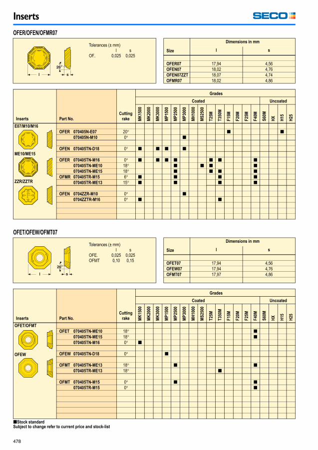
OFER 070405N-E07 20� [ [070405N-M10 0� [
OFEN 070405TN-D18 0� [ [ [ [
OFER 070405TN-M16 0� [ [ [ [ [ [ [070405TN-ME10 18� [ [ [ [070405TN-ME15 18� [ [ [ [
OFMR 070405TR-M15 6� [ [ [ [070405TR-ME13 15� [ [ [ [
OFEN 0704ZZR-M10 0� [0704ZZTR-M16 0� [ [
Inserts Part No.
Cutting
rake
Grades
Coated Uncoated
MK
150
0
MK
200
0
MK
300
0
MP
15
00
MP
25
00
MP
30
00
MH
100
0
MS
25
00
T2
5M
T3
50
M
F1
5M
F2
0M
F2
5M
F4
0M
S6
0M
HX
H1
5
H2
5
OFET/OFMT
OFEW
OFET 070405TN-ME10 18� [070405TN-ME15 18� [070405TN-M16 0� [
OFEW 070405TN-D18 0� [
OFMT 070405TN-ME13 18� [ [070405TR-ME13 18� [
OFMT 070405TN-M15 0� [ [070405TR-M15 0� [
OFER/OFEN/OFMR07
Tolerances (± mm)l s
OF.. 0,025 0,025Size
Dimensions in mm
l s
OFER07 17,94 4,56OFEN07 18,02 4,76OFEN07ZZT 18,07 4,74OFMR07 18,02 4,86
OFET/OFEW/OFMT07
Tolerances (± mm)l s
OFE. 0,025 0,025OFMT 0,10 0,15
Size
Dimensions in mm
l s
OFET07 17,94 4,56OFEW07 17,94 4,76OFMT07 17,97 4,86
[Stock standardSubject to change refer to current price and stock-list
Milling_090109.book Page 478 Friday, January 9, 2009 12:56 PM
Inserts
479
Inserts Part No.
Cutting
rake
Grades
Coated Uncoated
MK
15
00
MK
20
00
MK
30
00
MP
150
0
MP
250
0
MP
300
0
MH
10
00
MS
250
0
T2
5M
T3
50
M
F1
5M
F2
0M
F2
5M
F4
0M
S6
0M
HX
H1
5
H2
5
E06
ME07/ME12
M05
M08/D09/M14
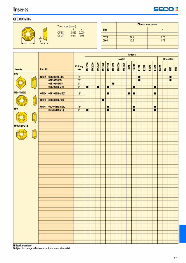
OFEX 05T305FR-E06 18� [ [05T305N-E04 20� [ [05T305N-M05 0� [05T305TN-M08 0� [ [ [ [ [
OFEX 05T305TN-ME07 18� [ [ [ [
OFEX 05T305TN-D09 [
OFMT 050405TR-ME12 18� [ [ [050405TR-M14 0� [ [ [ [
OFEX/OFMT05
Tolerances (± mm)l s
OFEX 0,025 0,025OFMT 0,08 0,05
Size
Dimensions in mm
l s
05T3 12,7 3,770504 13,3 4,76
[Stock standardSubject to change refer to current price and stock-list
Milling_090109.book Page 479 Friday, January 9, 2009 12:56 PM

Inserts
480
Inserts Part No. r�
Cutting
rake
Grades
Coated Uncoated
MK
15
00
MK
20
00
MK
30
00
MP
150
0
MP
250
0
MP
300
0
MH
10
00
MS
250
0
T2
5M
T3
50
M
F1
5M
F2
0M
F2
5M
F4
0M
S6
0M
HX
H1
5
H2
5
MD20
ODMT 050408TN-MD20 0,8 14� [ [ [ [ [
ODMT 050504TN-MD20 0,4 14� [
ODMT05
Tolerances (± mm)l s
ODMT 0,08 0,05Size
Dimensions in mm
l s
0504 12,7 4,76
[Stock standardSubject to change refer to current price and stock-list
Milling_090109.book Page 480 Friday, January 9, 2009 12:56 PM

Inserts
481
Inserts Part No.
Cutting
rake
Grades
Coated Uncoated
MK
15
00
MK
20
00
MK
30
00
MP
150
0
MP
250
0
MP
300
0
MH
10
00
MS
250
0
T2
5M
T3
50
M
F1
5M
F2
0M
F2
5M
F4
0M
S6
0M
HX
H1
5
H2
5
M14
ONMF 090520ANTN-M14 15� [ [ [ [ [090520ANTN-MD16 0� [ [ [ [
ONEF 090520ZZTN-M14 15� [ [ [
ON..09
Tolerances (± mm)l s
ONMF. 0,050 0,050ONEF 0,025 0,025
Size
Dimensions in mm
l s
ON..09 22 5,8
[Stock standardSubject to change refer to current price and stock-list
Milling_090109.book Page 481 Friday, January 9, 2009 12:56 PM

Inserts
482
Inserts Part No.
Cutting
rake
Grades
Coated Uncoated
MK
15
00
MK
20
00
MK
30
00
MP
150
0
MP
250
0
MP
300
0
MH
10
00
MS
250
0
T2
5M
T3
50
M
F1
5M
F2
0M
F2
5M
F3
0M
F4
0M
S6
0M
HX
H1
5
H2
5
E05/M07
R230.19 -1205-E05 20� [-1205-M07 0� [
Inserts Part No.
Cutting
rake
Grades
Coated Uncoated
MK
150
0
MK
200
0
MK
300
0
MP
15
00
MP
25
00
MP
30
00
MH
100
0
MS
25
00
T2
5M
T3
50
M
F1
5M
F2
0M
F2
5M
F3
0M
F4
0M
S6
0M
HX
H1
5
H2
5
E05
R235.15 -032-E05 8� [-050-E05 8� [ [-080-E05 8� [ [
R230.19
Tolerances (± mm)l s
R230.19 0,013 0,010Size
Dimensions in mm
l s
1205 12,70 5,4
R235.15
Size
Dimensions in mm
~ l
032 43,0050 54,7080 54,7
[Stock standardSubject to change refer to current price and stock-list
Milling_090109.book Page 482 Friday, January 9, 2009 12:56 PM

Inserts
483
Inserts Part No.
Cutting
rake
Grades
Coated Uncoated
T15
0M
T20
0M
T25
M
T25
0M
T35
0M
F15
M
F17
M
F20
M
F25
M
F30
M
F40
M
S10
M
S25
M
S60
M
HX
H1
5
H2
5
E08
M10
R335.15 -13110FG-E08 15� [-13130FG-E08 15� [-13160FG-E08 15� [-13185FG-E08 15� [-13215FG-E08 15� [-13265FG-E08 15� [
R335.15 -13215FG-M10 0� [-13265FG-M10 0� [
Inserts Part No.
Cutting
rake
Grades
Coated Uncoated
MK
15
00
MK
20
00
MK
30
00
MP
15
00
MP
25
00
MP
30
00
MH
10
00
MS
25
00
T2
5M
T3
50
M
F1
5M
F2
0M
F2
5M
F3
0M
F4
0M
S6
0M
HX
H15
H25
M12
R335.15 -18315FG-M12 0� [-18350FG-M12 0� [-18400FG-M12 0� [-18415FG-M12 0� [-18500FG-M12 0� [-18515FG-M12 0� [
R335.15-13..
Tolerances (mm)R335.15-.. ae 0 – +0,15
b 0 – +0,05Size
Dimensions in mm
~ l ae b
13110/13130 13,50/13,50 1,40/1,60 1,13/1,3313160 13,50 2,20 1,6313185 13,50 2,20 1,8813215 13,50 3,10 2,1813265 13,50 3,10 2,68
R335.15-18..
Tolerances (mm)R335.15-.. ae 0 – +0,15
b 0 – +0,05Size
Dimensions in mm
~ l ae b
18315 18,0 3,55 3,2018350 18,0 3,85 3,5518400 18,0 4,55 4,0518415 18,0 4,55 4,2018500 18,0 5,50 5,0518515 18,0 5,50 5,20
[Stock standardSubject to change refer to current price and stock-list
Milling_090109.book Page 483 Friday, January 9, 2009 12:56 PM

Inserts
484
Inserts Part No.
Cutting
rake
Grades
Coated Uncoated
MK
15
00
MK
20
00
MK
30
00
MP
150
0
MP
250
0
MP
300
0
MH
10
00
MS
250
0
T2
5M
T3
50
M
F1
5M
F2
0M
F2
5M
F4
0M
S6
0M
HX
H1
5
H2
5
ME12
M14/MD15
REHR 1605M0T-ME12 20� [1605M0T-M14 14� [ [ [ [1605M0T-MD15 6� [
REHR1605
Tolerances (± mm)D s
REHR 0,013 0,25Size
Dimensions in mm
D s
1605 16,0 5,56
[Stock standardSubject to change refer to current price and stock-list
Milling_090109.book Page 484 Friday, January 9, 2009 12:56 PM

Inserts
485
Inserts Part No.
Cutting
rake
Grades
Coated Uncoated
MK
15
00
MK
20
00
MK
30
00
MP
150
0
MP
250
0
MP
300
0
MH
10
00
MS
250
0
T2
5M
T3
50
M
F1
5M
F2
0M
F2
5M
F4
0M
S6
0M
HX
H1
5
H2
5
E02/E03/E04
M05/M07
MD02/MD03/MD04/
MD05/MD06
RDHW 0501M0-MD01 0� [ [ [
RDHT 0702M0-E03 18� [ [
RDHW 0702M0-MD03 0� [ [
RDHW 0702M0-MD04 0� [ [ [ [
RD..05/07
Tolerances (± mm)D s
RDHW 0,013 0,025RDHT 0,013 0,025
Size
Dimensions in mm
D s
0501 5 1,510702 7 2,38
[Stock standardSubject to change refer to current price and stock-list
Milling_090109.book Page 485 Friday, January 9, 2009 12:56 PM

Inserts
486
Inserts Part No.
Cutting
rake
Grades
Coated Uncoated
MK
15
00
MK
20
00
MK
30
00
MP
150
0
MP
250
0
MP
300
0
MH
10
00
MS
250
0
T2
5M
T3
50
M
F1
5M
F2
0M
F2
5M
F4
0M
S6
0M
HX
H1
5
H2
5
E02/E03/E04
M05/M07
MD02/MD03/MD04/
MD05/MD06
RDHT 06T1M0-E02 18� [ [0803M0-E03 20� [ [ [10T3M0-E04 20� [ [ [10T3M0T-M05 16� [ [ [ [ [10T3M0T-M07 11� [ [ [ [
RDHW 06T1M0-MD02 0� [ [ [ [0803M0-MD03 0� [ [10T3M0-MD04 0� [ [10T3M0T-MD06 0� [ [ [
RDKW 0803M0T-MD05 0� [ [ [ [ [ [10T3M0T-MD06 0� [ [ [ [ [ [ [
RD..06/08/10
Tolerances (± mm)D s
RDHT 0,013 0,025RDHW 0,013 0,025RDKW 0,05 0,025
Size
Dimensions in mm
D s
06T1 6,0 2,180803 8,0 3,1810T3 10,0 3,97
[Stock standardSubject to change refer to current price and stock-list
Milling_090109.book Page 486 Friday, January 9, 2009 12:56 PM

Inserts
487
Inserts Part No.
Cutting
rake
Grades
Coated Uncoated
MK
15
00
MK
20
00
MK
30
00
MP
150
0
MP
250
0
MP
300
0
MH
10
00
MS
250
0
T2
5M
T3
50
M
F1
5M
F2
0M
F2
5M
F4
0M
S6
0M
HX
H1
5
H2
5
ME07
E05/MD05
M08/M15/MD10
M10
RPHT 1204M0T-M08 16� [ [ [ [ [1204M0-E05 20� [ [ [1204M0T-ME07 20� [ [ [1204M0T-M15 15� [ [ [ [ [ [ [1204M0T-M10 11� [ [ [ [
RPHW 1204M0-MD05 0� [ [1204M0T-MD10 0� [
RPKW 1204M0T-MD10 0� [ [ [ [ [
RP..12
Tolerances (± mm)D s
RPH. 0,013 0,025RPKW 0,08 0,025
Size
Dimensions in mm
D s
1204 12,0 4,76
[Stock standardSubject to change refer to current price and stock-list
Milling_090109.book Page 487 Friday, January 9, 2009 12:56 PM

Inserts
488
Inserts Part No.
Cutting
rake
Grades
Coated Uncoated
MK
15
00
MK
20
00
MK
30
00
MP
150
0
MP
250
0
MP
300
0
MH
10
00
MS
250
0
T2
5M
T3
50
M
F1
5M
F2
0M
F2
5M
F4
0M
S6
0M
HX
H1
5
H2
5
ME11/ME12
M10/M14/D15/M18
E08/E10
RPHT 1605M0T-ME11 21� [ [ [ [1605M0-E08 21� [1605M0T-M12 15� [ [ [ [1605M0T-M18 15� [ [ [ [ [ [ [
RPKW 1605M0T-MD20 0� [ [ [ [ [ [
RPHW 1605M0T-MD08 0� [ [
RPHT 2006M0-E10 21� [2006M0T-ME12 20� [ [ [ [
RPKT 2006M0T-M15 15� [ [ [ [2006M0T-M20 15� [ [ [ [ [ [ [
RPKW 2006M0T-MD22 0� [ [ [ [ [2006M0-MD10 0� [ [
RP..16/20
Tolerances (± mm)D s
RPHT 0,013 0,25RPKX 0,013 0,25RPHW 0,013 0,25
Size
Dimensions in mm
D s
1605 16,0 5,562006 20,0 6,35
[Stock standardSubject to change refer to current price and stock-list
Milling_090109.book Page 488 Friday, January 9, 2009 12:56 PM

Inserts
489
Inserts Part No. r�
Cutting
rake
Grades
Coated Uncoated
MK
15
00
MK
20
00
MK
30
00
MP
150
0
MP
250
0
MP
300
0
MH
10
00
MS
250
0
T2
5M
T3
50
M
F1
5M
F2
0M
F2
5M
F4
0M
S6
0M
HX
H1
5
H2
5
E08
ME10
M11/M14/MD15
SCEX 120612-E08 1,2 26� [
SCET 120612T-ME10 1,2 22� [
SCET 120612T-M11 1,2 14� [ [ [ [ [120612T-M14 1,2 15� [ [ [ [ [ [120612T-MD15 1,2 15� [ [
SCET 120630T-M14 3,0 15� [ [ [ [ [ [120631T-ME10 3,1 22� [120631T-M11 3,1 14� [
SCEX 120660T-M14 6,0 15� [
SCMT 120612T-M14 1,2 15� [ [
SCET 120630T-MD16 3,0 15� [ [ [ [ [
SC..12
Tolerances (± mm)l s m
SCE. 0,025 0,025 0,025SCM. 0,08 0,13 0,13
Size
Dimensions in mm
l s
1206 12,7 6,35
[Stock standardSubject to change refer to current price and stock-listWhen using inserts with corner radius > 3 mm, the cutter body must be modified.
Milling_090109.book Page 489 Friday, January 9, 2009 12:56 PM

Inserts
490
Inserts Part No. B
Cutting
rake
Grades
Coated Uncoated
MK
15
00
MK
20
00
MK
30
00
MP
150
0
MP
250
0
MP
300
0
MH
10
00
MS
250
0
T2
5M
T3
50
M
F1
5M
F2
0M
F2
5M
F3
0M
F4
0M
S6
0M
HX
H1
5
H2
5
SEAN 1203AFN-E12 1,6 0� [ [1203AFTN-M14 1,6 0� [ [ [ [
SEAN 1303AFN-E12 3,5 0� [1303AFTN-M14 3,5 0� [1303AFTN-M15 3,5 0� [
SEAN 1604AFN-E15 4,1 0� [1604AFTN-M18 4,1 0� [1604AFTN-M19 4,1 0� [
Inserts Part No.
Cutting
rake
Grades
Coated Uncoated
MK
150
0
MK
200
0
MK
300
0
MP
15
00
MP
25
00
MP
30
00
MH
100
0
MS
25
00
T2
5M
T3
50
M
F1
5M
F2
0M
F2
5M
F4
0M
S1
0M
HX
H1
5
H2
5
SEAN 1203ZZN-E12 0� [1203ZZTN-M14 0� [1203ZZTN-M15 0� [1203ZZTN-MD15 0� [
SEAN 1504ZZTN-M18 0� [ [
SEAN..
Tolerances (± mm)l s m
SEAN 0,025 0,025 0,007Size
Dimensions in mm
l s
1203 12,7 3,181303 13,44 3,361604 16,8 4,79
SEAN..ZZ..
Tolerances (± mm)l s m
SEAN 0,025 0,025 0,007Size
Dimensions in mm
l s
1203 12,7 3,181504 15,875 4,76
[Stock standardSubject to change refer to current price and stock-list
Milling_090109.book Page 490 Friday, January 9, 2009 12:56 PM

Inserts
491
Inserts Part No. B
Cutting
rake
Grades
Coated Uncoated
MK
15
00
MK
20
00
MK
30
00
MP
150
0
MP
250
0
MP
300
0
MH
10
00
MS
250
0
T2
5M
T3
50
M
F1
5M
F2
0M
F2
5M
F4
0M
S1
0M
HX
H1
5
H2
5
SEKN 1203AFN-E12 1,6 0� [ [ [1203AFTN-M14 1,6 0� [ [ [ [ [ [ [1203AFTN-D16 1,6 0� [
SEKN 1204AFTN-M18 1,5 0� [ [
SEKN 1504AFN-E15 1,6 0� [ [ [1504AFTN-M18 1,6 0� [ [ [ [ [ [1504AFTN-MD20 1,6 0� [
SEKN..
Tolerances (± mm)l s m
SEKN12 0,08 0,025 0,013-M14 0,08 0,025 0,03SEKN15 0,10 0,025 0,013-M18 0,05 0,025 0,05
Size
Dimensions in mm
l s
1203 12,70 3,181204 12,70 4,761504 15,875 4,76
[Stock standardSubject to change refer to current price and stock-list
Milling_090109.book Page 491 Friday, January 9, 2009 12:56 PM

Inserts
492
Inserts Part No. B
Cutting
rake
Grades
Coated Uncoated
MK
15
00
MK
20
00
MK
30
00
MP
150
0
MP
250
0
MP
300
0
MH
10
00
MS
250
0
T2
5M
T3
50
M
F1
5M
F2
0M
F2
5M
F4
0M
S6
0M
HX
H1
5
H2
5
E07
ME10/ME16
SEKR 1203AFN-E07 1,6 18� [ [ [
SEKR 1203AFTN-ME10 1,5 20� [ [ [ [1203AFTN-ME13 1,5 24� [ [ [ [ [ [
SEKR 1303AFTN-ME13 3,5 24� [ [
SEKR 1504AFTN-ME12 1,5 20� [1504AFTN-ME16 1,5 20� [ [
SEKR 1604AFTN-ME16 4,1 20� [
Inserts Part No.
Cutting
rake
Grades
Coated Uncoated
MK
150
0
MK
200
0
MK
300
0
MP
15
00
MP
25
00
MP
30
00
MH
100
0
MS
25
00
T2
5M
T3
50
M
F1
5M
F2
0M
F2
5M
F4
0M
S6
0M
HX
H1
5
H2
5
SEKR 1203ZZN-E07 18� [
SEKR
Tolerances (± mm)l s m
SEKR12/13 0,08 0,025 0,013SEKR15 0,10 0,025 0,05SEKR16 0,10 0,025 0,013
Size
Dimensions in mm
l s
1203 12,7 3,181303 13,44 3,361504 15,875 4,761604 16,8 4,79
SEKR..ZZ
Tolerances (± mm)l s m
SEKR..ZZ 0,08 0,025 0,013Size
Dimensions in mm
l s
1203 12,7 3,18
[Stock standardSubject to change refer to current price and stock-list
Milling_090109.book Page 492 Friday, January 9, 2009 12:56 PM

Inserts
493
Inserts Part No. B
Cutting
rake
Grades
Coated Uncoated
MK
15
00
MK
20
00
MK
30
00
MP
150
0
MP
250
0
MP
300
0
MH
10
00
MS
250
0
T2
5M
T3
50
M
F1
5M
F2
0M
F2
5M
F4
0M
S6
0M
HX
H1
5
H2
5
ME07
M08
SEEX 09T3AFN-E04 1,5 25� [ [ [09T3AFN-M05 1,5 0� [ [09T3AFTN-ME07 1,5 22� [ [ [ [09T3AFTN-M08 1,5 0� [ [ [ [ [ [09T3AFTN-D09 1,5 0� [
Inserts Part No. r�
Cutting
rake
Grades
Coated Uncoated
MK
150
0
MK
200
0
MK
300
0
MP
15
00
MP
25
00
MP
30
00
MH
100
0
MS
25
00
T2
5M
T3
50
M
F1
5M
F2
0M
F2
5M
F4
0M
S6
0M
HX
H1
5
H2
5
SEEX 1203AFTN-M13 1,6 0� [1203AFTN-MD14 1,6 0� [ [ [ [
SEEX09
Tolerances (± mm)l s m
SEEX 0,025 0,025 0,025Size
Dimensions in mm
l s
09T3 9,525 3,97
SEEX1203
Tolerances (± mm)l s m
SEEX 0,025 0,025 0,025Size
Dimensions in mm
l s
1203 12,77 3,18
[Stock standardSubject to change refer to current price and stock-list
Milling_090109.book Page 493 Friday, January 9, 2009 12:56 PM

Inserts
494
Inserts Part No. r�
Cutting
rake
Grades
Coated Uncoated
MK
15
00
MK
20
00
MK
30
00
MP
150
0
MP
250
0
MP
300
0
MH
10
00
MS
250
0
T2
5M
T3
50
M
F1
5M
F2
0M
F2
5M
F4
0M
S6
0M
HX
H1
5
H2
5
SENN 120308-E10 0,8 0� [120308T-M12 0,8 0� [
Inserts Part No. B
Cutting
rake
Grades
Coated Uncoated
MK
150
0
MK
200
0
MK
300
0
MP
15
00
MP
25
00
MP
30
00
MH
100
0
MS
25
00
T2
5M
T3
50
M
F1
5M
F2
0M
F2
5M
F4
0M
S6
0M
HX
H1
5
H2
5
ME06
M08
SEMX 09T3AFTN-ME06 1,5 25� [ [ [09T3AFTN-M08 1,5 0� [ [ [
SENN12
Tolerances (± mm)l s m
SENN 0,08 0,025 0,13Size
Dimensions in mm
l s
1203 12,7 3,18
SEMX09
Tolerances (± mm)l s m
SEMX 0,05 0,13 0,08Size
Dimensions in mm
l s
09T3 9,525 3,97
[Stock standardSubject to change refer to current price and stock-list
Milling_090109.book Page 494 Friday, January 9, 2009 12:56 PM

Inserts
495
Inserts Part No. B
Cutting
rake
Grades
Coated Uncoated
MK
15
00
MK
20
00
MK
30
00
MP
150
0
MP
250
0
MP
300
0
MH
10
00
MS
250
0
T2
5M
T3
50
M
F1
5M
F2
0M
F2
5M
F4
0M
S6
0M
HX
H1
5
H2
5
ME12/M15
MD19
SEMX 1204AFTN-ME12 1,57 18� [ [ [1204AFTN-M15 1,57 7� [ [ [ [ [ [ [
SEMX 1204AFTN-MD19 1,57 0� [ [ [ [
Inserts Part No. B
Cutting
rake
Grades
Coated Uncoated
MK
150
0
MK
200
0
MK
300
0
MP
15
00
MP
25
00
MP
30
00
MH
100
0
MS
25
00
T2
5M
T3
50
M
F1
5M
F2
0M
F2
5M
F4
0M
S6
0M
HX
H1
5
H2
5
E08/MD18
ME11/M10/M14
ZZTN
SEEX 1204AFN-E08 1,57 25� [ [1204AFN-M10 1,57 7� [ [ [ [
SEEX 1204AFTN-ME11 1,57 18� [ [ [
SEEX 1204AFTN-M14 1,57 7� [ [ [ [ [ [ [
SEEX 1204AFTN-MD18 1,57 0� [ [ [ [ [
SEEX 1204ZZTN-M14 – 0� [ [ [ [ [
SEMX12
Tolerances (± mm)l s m
SEMX 0,03 0,025 0,03Size
Dimensions in mm
l s
1204 12,7 4,76
SEEX1204
Tolerances (± mm)l s m
SEEX 0,025 0,025 0,025Size
Dimensions in mm
l s
1204 12,7 4,76
* Only to be used together with SEEX1204.. inserts.
Milling_090109.book Page 495 Friday, January 9, 2009 12:56 PM
Inserts
496
Inserts Part No. B
Cutting
rake
Grades
Coated Uncoated
MK
15
00
MK
20
00
MK
30
00
MP
150
0
MP
250
0
MP
300
0
MH
10
00
MS
250
0
T2
5M
T3
50
M
F1
5M
F2
0M
F2
5M
F4
0M
S6
0M
HX
H1
5
H2
5
E10
M17/M12
ZZTN
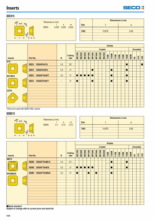
SEEX 1505AFN-E10 1,8 25� [ [
SEEX 1505AFN-M12 1,8 5� [ [ [
SEEX 1505AFTN-M17 1,8 5� [ [ [ [ [ [ [
SEEX 1505ZZTN-M17 – 5� [ [ [ [
Inserts Part No. B
Cutting
rake
Grades
Coated Uncoated
MK
150
0
MK
200
0
MK
300
0
MP
15
00
MP
25
00
MP
30
00
MH
100
0
MS
25
00
T2
5M
T3
50
M
F1
5M
F2
0M
F2
5M
F4
0M
S6
0M
HX
H1
5
H2
5
ME15
M18/MD20
SEMX 1505AFTN-ME15 1,8 21� [ [
SEMX 1505AFTN-M18 1,8 5� [ [ [ [ [ [ [
SEMX 1505AFTN-MD20 1,8 0� [ [ [ [
SEEX15
Tolerances (± mm)l s m
SEEX 0,025 0,025 0,025Size
Dimensions in mm
l s
1505 15,875 5,56
*Only to be used with SEEX1505..inserts
SEMX15
Tolerances (± mm)l s m
SEMX 0,1 0,13 0,15Size
Dimensions in mm
l s
1505 15,875 5,56
[Stock standardSubject to change refer to current price and stock-list
Milling_090109.book Page 496 Friday, January 9, 2009 12:56 PM
Inserts
497
Inserts Part No. B
Cutting
rake
Grades
Coated Uncoated
MK
15
00
MK
20
00
MK
30
00
MP
150
0
MP
250
0
MP
300
0
MH
10
00
MS
250
0
T2
5M
T3
50
M
F1
5M
F2
0M
F2
5M
F4
0M
S6
0M
HX
H1
5
H2
5
MD15
M14
ME10
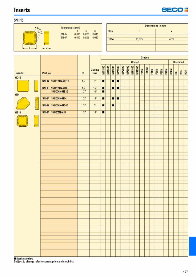
SNHN 150412TN-MD15 1,2 0� [ [ [
SNHF 150412TN-M14 1,2 15� [ [ [1504XNN-ME10 1,37 10� [
SNHF 1504XNN-M14 1,37 15� [ [ [
SNHN 1504XNN-MD15 1,37 0� [ [
SNHF 1504ZZN-M14 1,37 15� [
SNH.15
Tolerances (± mm)l s m
SNHN 0,013 0,025 0,013SNHF 0,013 0,025 0,013
Size
Dimensions in mm
l s
1504 15,875 4,76
[Stock standardSubject to change refer to current price and stock-list
Milling_090109_13.fm Page 497 Monday, January 19, 2009 9:49 AM

Inserts
498
Inserts Part No. r�
Cut-
ting rake
Grades
Coated Uncoated
MK
15
00
MK
20
00
MK
30
00
MP
15
00
MP
25
00
MP
30
00
MH
10
00
MS
25
00
T25
M
T35
0M
F15
M
F20
M
F25
M
F30
M
F40
M
S60
M
HX
H1
5
H2
5
SNHQ 120320EL2-M07 2,0 20� [120324EL2-M07 2,4 20� [120330EL2-M07 3,0 20� [
SNHQ 120320ER2-M07 2,0 20� [120324ER2-M07 2,4 20� [120330ER2-M07 3,0 20� [
SNHQ 120424EL2-M07 2,4 20� [120431EL2-M07 3,1 20� [120435EL2-M07 3,5 20� [
SNHQ 120424ER2-M07 2,4 20� [120431ER2-M07 3,1 20� [120435ER2-M07 3,5 20� [
SNHQ 1204524EL2-M07 2,4 20� [1204531EL2-M07 3,1 20� [1204540EL2-M07 4,0 20� [
SNHQ 1204524ER2-M07 2,4 20� [1204531ER2-M07 3,1 20� [1204540ER2-M07 4,0 20� [
SNHQ 120524EL2-M07 2,4 20� [120531EL2-M07 3,1 20� [120540EL2-M07 4,0 20� [120550EL2-M07 5,0 20� [
SNHQ 120524ER2-M07 2,4 20� [120531ER2-M07 3,1 20� [120540ER2-M07 4,0 20� [120550ER2-M07 5,0 20� [
SNHQ 120724EL2-M07 2,4 20� [120731EL2-M07 3,1 20� [120740EL2-M07 4,0 20� [120750EL2-M07 5,0 20� [120760EL2-M07 6,0 20� [
SNHQ 120724ER2-M07 2,4 20� [120731ER2-M07 3,1 20� [120740ER2-M07 4,0 20� [120750ER2-M07 5,0 20� [120760ER2-M07 6,0 20� [
SNHQ 2 edges
Tolerances (± mm)l s
SNHQ 0,013 0,01Size
Dimensions in mm
l s
1203 12,7 3,251204 12,7 4,0212045 12,7 4,571205 12,7 5,471207 12,7 7,08
[Stock standard
Subject to change refer to current price and stock-list
When using inserts with corner radius > 4,0 mm, the cutter must be modified
Milling_090109.book Page 498 Friday, January 9, 2009 12:56 PM
Inserts
499
Inserts Part No. r�
Cut-
ting rake
Grades
Coated Uncoated
MK
15
00
MK
20
00
MK
30
00
MP
150
0
MP
250
0
MP
300
0
MH
10
00
MS
250
0
T2
5M
T3
50
M
F1
5M
F2
0M
F2
5M
F3
0M
F4
0M
S6
0M
HX
H1
5
H2
5
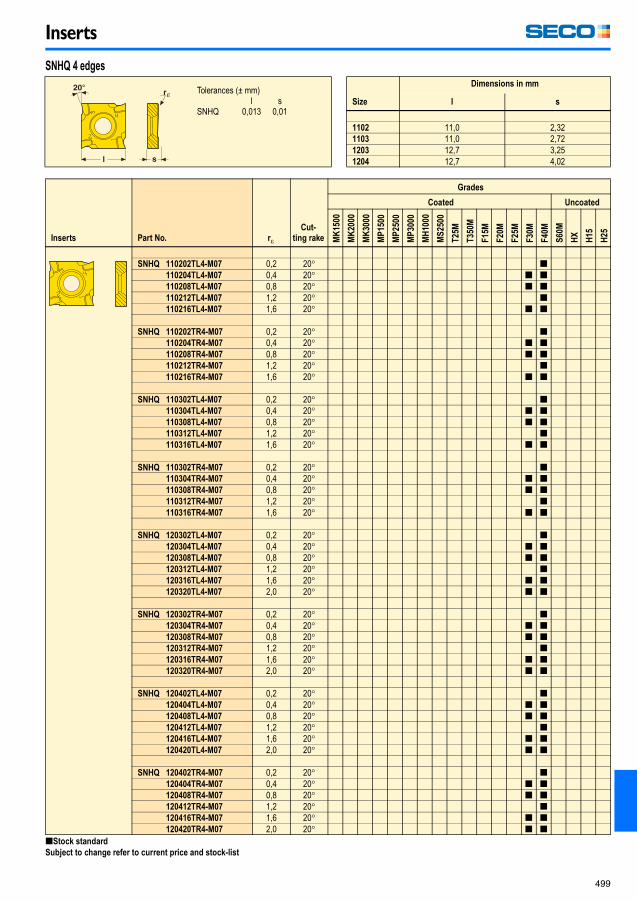
SNHQ 110202TL4-M07 0,2 20� [110204TL4-M07 0,4 20� [ [110208TL4-M07 0,8 20� [ [110212TL4-M07 1,2 20� [110216TL4-M07 1,6 20� [ [
SNHQ 110202TR4-M07 0,2 20� [110204TR4-M07 0,4 20� [ [110208TR4-M07 0,8 20� [ [110212TR4-M07 1,2 20� [110216TR4-M07 1,6 20� [ [
SNHQ 110302TL4-M07 0,2 20� [110304TL4-M07 0,4 20� [ [110308TL4-M07 0,8 20� [ [110312TL4-M07 1,2 20� [110316TL4-M07 1,6 20� [ [
SNHQ 110302TR4-M07 0,2 20� [110304TR4-M07 0,4 20� [ [110308TR4-M07 0,8 20� [ [110312TR4-M07 1,2 20� [110316TR4-M07 1,6 20� [ [
SNHQ 120302TL4-M07 0,2 20� [120304TL4-M07 0,4 20� [ [120308TL4-M07 0,8 20� [ [120312TL4-M07 1,2 20� [120316TL4-M07 1,6 20� [ [120320TL4-M07 2,0 20� [ [
SNHQ 120302TR4-M07 0,2 20� [120304TR4-M07 0,4 20� [ [120308TR4-M07 0,8 20� [ [120312TR4-M07 1,2 20� [120316TR4-M07 1,6 20� [ [120320TR4-M07 2,0 20� [ [
SNHQ 120402TL4-M07 0,2 20� [120404TL4-M07 0,4 20� [ [120408TL4-M07 0,8 20� [ [120412TL4-M07 1,2 20� [120416TL4-M07 1,6 20� [ [120420TL4-M07 2,0 20� [ [
SNHQ 120402TR4-M07 0,2 20� [120404TR4-M07 0,4 20� [ [120408TR4-M07 0,8 20� [ [120412TR4-M07 1,2 20� [120416TR4-M07 1,6 20� [ [120420TR4-M07 2,0 20� [ [
SNHQ 4 edges
Tolerances (± mm)l s
SNHQ 0,013 0,01Size
Dimensions in mm
l s
1102 11,0 2,321103 11,0 2,721203 12,7 3,251204 12,7 4,02
[Stock standard
Subject to change refer to current price and stock-list
Milling_090109.book Page 499 Friday, January 9, 2009 12:56 PM

Inserts
500
Inserts Part No. r�
Cut-
ting rake
Grades
Coated Uncoated
MK
15
00
MK
20
00
MK
30
00
MP
150
0
MP
250
0
MP
300
0
MH
10
00
MS
250
0
T2
5M
T3
50
M
F1
5M
F2
0M
F2
5M
F3
0M
F4
0M
S6
0M
HX
H1
5
H2
5
SNHQ 1204502TL4-M07 0,2 20� [1204504TL4-M07 0,4 20� [ [1204508TL4-M07 0,8 20� [ [1204512TL4-M07 1,2 20� [1204516TL4-M07 1,6 20� [ [1204520TL4-M07 2,0 20� [ [
SNHQ 1204502TR4-M07 0,2 20� [1204504TR4-M07 0,4 20� [ [1204508TR4-M07 0,8 20� [ [1204512TR4-M07 1,2 20� [1204516TR4-M07 1,6 20� [ [1204520TR4-M07 2,0 20� [ [
SNHQ 120502TL4-M07 0,2 20� [120504TL4-M07 0,4 20� [ [120508TL4-M07 0,8 20� [ [120512TL4-M07 1,2 20� [120516TL4-M07 1,6 20� [ [120520TL4-M07 2,0 20� [ [
SNHQ 120502TR4-M07 0,2 20� [120504TR4-M07 0,4 20� [ [120508TR4-M07 0,8 20� [ [120512TR4-M07 1,2 20� [120516TR4-M07 1,6 20� [ [120520TR4-M07 2,0 20� [ [
SNHQ 120702TL4-M07 0,2 20� [120704TL4-M07 0,4 20� [ [120708TL4-M07 0,8 20� [ [120712TL4-M07 1,2 20� [120716TL4-M07 1,6 20� [ [120720TL4-M07 2,0 20� [ [
SNHQ 120702TR4-M07 0,2 20� [120704TR4-M07 0,4 20� [ [120708TR4-M07 0,8 20� [ [120712TR4-M07 1,2 20� [120716TR4-M07 1,6 20� [ [120720TR4-M07 2,0 20� [ [
SNHQ 4 edges
Tolerances (± mm)l s
SNHQ 0,013 0,01Size
Dimensions in mm
l s
12045 12,7 4,571205 12,7 5,471207 12,7 7,08
[Stock standard
Subject to change refer to current price and stock-list
Milling_090109.book Page 500 Friday, January 9, 2009 12:56 PM

Inserts
501
Inserts Part No. r�
Cut-
ting rake
Grades
Coated Uncoated
MK
15
00
MK
20
00
MK
30
00
MP
15
00
MP
25
00
MP
30
00
MH
10
00
MS
25
00
T2
5M
T3
50M
F1
5M
F2
0M
F2
5M
F3
0M
F4
0M
S6
0M
HX
H1
5
H2
5
SNHQ 110202EL4-E05 0,2 20� [ [110202ER4-E05 0,2 20� [ [
SNHQ 110302EL4-E05 0,2 20� [ [110302ER4-E05 0,2 20� [ [
SNHQ 120302EL4-E05 0,2 20� [ [120302ER4-E05 0,2 20� [ [
SNHQ 120404EL4-E05 0,4 20� [ [120404ER4-E05 0,4 20� [ [
SNHQ 1204504EL4-E05 0,4 20� [ [1204504ER4-E05 0,4 20� [ [
SNHQ 120504EL4-E05 0,4 20� [ [120504ER4-E05 0,4 20� [ [
SNHQ 120704EL4-E05 0,4 20� [ [120704ER4-E05 0,4 20� [ [
SNHQ 4 edges
Tolerances (± mm)l s
SNHQ 0,013 0,01Size
Dimensions in mm
l s
1102 11,0 2,321103 11,0 2,721203 12,7 3,251204 12,7 4,0212045 12,7 4,571205 12,7 5,471207 12,7 7,08
[Stock standard
Subject to change refer to current price and stock-list
Milling_090109.book Page 501 Friday, January 9, 2009 12:56 PM

Inserts
502
Inserts Part No. r�
Cutting
rake
Grades
Coated Uncoated
MK
15
00
MK
20
00
MK
30
00
MP
150
0
MP
250
0
MP
300
0
MH
10
00
MS
250
0
T2
5M
T3
50
M
F1
5M
F2
0M
F2
5M
F4
0M
S6
0M
HX
H1
5
H2
5
ME06/ME08/ME10
M10/M12/M14
SONX 09T304TR-ME06 0,4 22� [09T304TR-M10 0,4 19� [ [ [ [ [09T308TR-M10 0,8 19� [ [ [ [ [ [
SONX 120508TR-ME08 0,8 24� [120508TR-M12 0,8 16� [ [ [ [ [ [
SONX 150508TR-ME10 0,8 19� [150508TR-M14 0,8 22� [ [ [ [ [ [150516TR-M14 1,6 22� [ [ [
SONX
Tolerances (± mm)l s
SONX 0,03 0,025Size
Dimensions in mm
l s
09T3 9,55 3,971205 12,7 5,171505 15,8 5,56
[Stock standardSubject to change refer to current price and stock-list
Milling_090109.book Page 502 Friday, January 9, 2009 12:56 PM

Inserts
503
Inserts Part No. B
Cutting
rake
Grades
Coated Uncoated
MK
15
00
MK
20
00
MK
30
00
MP
150
0
MP
250
0
MP
300
0
MH
10
00
MS
250
0
T2
5M
T3
50
M
F1
5M
F2
0M
F2
5M
F4
0M
S6
0M
HX
H1
5
H2
5
SPER
SPEN
SPER 1906ZETR-M17 1,0 17� [
SPEN 1906ZETR-D25 1,0 0� [ [
SPEN 1906ZETR-MD20 1,0 0� [ [ [ [1906ZETL-MD20 1,0 0� [
SPEN 2807ZETR-D35 1,5 0� [2807ZETR-MD35 1,5 0� [
Inserts Part No. re
Cutting
rake
Grades
Coated Uncoated
MK
150
0
MK
200
0
MK
300
0
MP
15
00
MP
25
00
MP
30
00
MH
100
0
MS
25
00
T2
5M
T3
50
M
F1
5M
F2
0M
F2
5M
F4
0M
S6
0M
HX
H1
5
H2
5
D35
M17/D25/MD20
SPER 1906ZZTR-M17 1,6 17� [1906ZZTL-M17 1,6 17� [
SPEN 1906ZZTR-D25 1,0 0� [ [1906ZZTR-MD20 1,0 0� [ [2807ZZTR-D35 2,1 0� [
SPE.
Tolerances (± mm)l s m
SPEN 0,025 0,025 0,025SPER 0,025 0,025 0,025
Size
Dimensions in mm
l s
1906 19,05 6,352807 28,575 7,94
SPE.-ZZ
Tolerances (± mm)l s m
SPER 0,025 0,025 0,025SPEN 0,025 0,025 0,025
Size
Dimensions in mm
l s B
1906 20,00 6,35 122807 28,575 7,94 8,5
[Stock standardSubject to change refer to current price and stock-list
Milling_090109.book Page 503 Friday, January 9, 2009 12:56 PM
Inserts
504
Inserts Part No. r�
Cut-
ting
rake
Grades
Coated Uncoated
T1
50
M
T2
00
M
T2
5M
T2
50
M
T3
50
M
F1
5M
F1
7M
F2
0M
F2
5M
F3
0M
F4
0M
S1
0M
S2
5M
S6
0M
HX
H1
5
H2
5
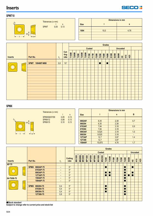
SPMT 100408T-M08 0,8 10� [ [
Inserts Part No. r�
Cutting
rake
Grades
Coated Uncoated
MK
15
00
MK
20
00
MK
30
00
MP
150
0
MP
250
0
MP
300
0
MH
10
00
MS
250
0
T2
5M
T3
50
M
F1
5M
F2
0M
F2
5M
F4
0M
S6
0M
HX
H1
5
H2
5
AP-75
04-75/08-75
SPMX 0602AP-75 – 5� [ [ [0703AP-75 – 5� [0903AP-75 – 5� [ [ [ [12T3AP-75 – 5� [ [ [ [ [1504AP-75 – 5� [1904AP-75 – 5� [
SPMX 060204-75 0,4 5� [ [070304-75 0,4 5� [ [090304-75 0,4 5� [ [12T308-75 0,8 5� [
SPMT10
Tolerances (± mm)l s
SPMT 0,05 0,13Size
Dimensions in mm
l s
1004 10,0 4,76
SPMX
Tolerances (± mm)l s
SPMX06/07/09 0,05 0,13SPMX12 0,08 0,13SPMX15 0,10 0,13
Size
Dimensions in mm
l s B
0602AP. 6,35 2,38 0,7060204 6,35 2,38 -0703AP. 7,94 3,18 0,9070304 7,94 3,18 -0903AP. 9,525 3,18 1,0090304 9,525 3,18 -12T3AP 12,7 3,97 1,412T308 12,7 3,97 -1504AP. 15,875 4,76 1,7
[Stock standardSubject to change refer to current price and stock-list
Milling_090109.book Page 504 Friday, January 9, 2009 12:56 PM

Inserts
505
Inserts Part No. r�
Cutting
rake
Grades
Coated Uncoated
T1
50
M
T2
00
M
T2
5M
T2
50
M
T3
50
M
F1
5M
F1
7M
F2
0M
F2
5M
F3
0M
F4
0M
S1
0M
S2
5M
S6
0M
HX
H1
5
H2
5
VPGX 220631EN-E10 3,1 25� [220631FN-E06 3,1 25� [
Inserts Part No. r�
Cutting
rake
Grades
Coated Uncoated
T1
50
M
T2
00
M
T2
5M
T2
50
M
T3
50
M
F1
5M
F1
7M
F2
0M
F2
5M
F3
0M
F4
0M
S1
0M
S2
5M
S6
0M
HX
H1
5
H2
5
VPGX 220605ER-E10 0,45 25� [220605FR-E06 0,45 25� [220616ER-E10 1,6 25� [220620ER-E10 2,0 25� [220624ER-E10 2,44 25� [220640ER-E10 4,0 25� [220640FR-E06 4,0 25� [220648ER-E10 4,88 25� [220663ER-E10 6,22 25� [
VPGX
Tolerances (± mm)s m
VPGX 0,13 0,025Size
Dimensions in mm
~ l s
2206 14 6,35
VPGX
Tolerances (± mm)s m
VPGX 0,13 0,025Size
Dimensions in mm
~ l s
2206 14 6,35
[Stock standard
Subject to change refer to current price and stock-list
When using inserts with corner radius >4,0 mm, the cutter must be modified. *Insert with viper flat 1,5 mm
Milling_090109.book Page 505 Friday, January 9, 2009 12:56 PM

Inserts
506
Inserts Part No. r�
Cutting
rake
Grades
Coated Uncoated
MK
15
00
MK
20
00
MK
30
00
MP
150
0
MP
250
0
MP
300
0
MH
10
00
MS
250
0
T2
5M
T3
50
M
F1
5M
F2
0M
F2
5M
F4
0M
S6
0M
HX
H1
5
H2
5
XCMX 050204T-MD05 0,4 0� [120408T-MD11 0,8 0� [
XCMX05/12
Tolerances (± mm)d s m
XCMX05 0,05 0,13 0,08XCMX12 0,08 0,13 0,13
Size
Dimensions in mm
~ l d s
05 6,35 5,65 2,3812 12,7 9,525 4,76
[Stock standard
Subject to change refer to current price and stock-list
Milling_090109.book Page 506 Friday, January 9, 2009 12:56 PM

Inserts
507
Inserts Part No. r�
Cutting
rake
Grades
Coated Uncoated
MK
15
00
MK
20
00
MK
30
00
MP
150
0
MP
250
0
MP
300
0
MH
10
00
MS
250
0
T2
5M
T3
50
M
F1
5M
F2
0M
F2
5M
F4
0M
S6
0M
HX
H1
5
H2
5
ME09/M13/MD15
XNEX 080608TR-ME09 0,8 27� [ [ [ [ [ [ [ [080608TR-M13 0,8 22� [ [ [ [ [ [ [ [080608TR-MD15 0,8 17� [ [ [ [ [ [ [ [
XNEX 080616TR-ME09 1,6 27� [ [ [ [ [ [ [ [080616TR-M13 1,6 22� [ [ [ [ [ [ [ [080616TR-MD15 1,6 17� [ [ [ [ [ [ [ [
XNEX
Tolerances (± mm)l s
XNEX 0,025 0,025Size
Dimensions in mm
l s
0806 12,48 6,37 - 6,47
[Stock standardSubject to change refer to current price and stock-list
Milling_090109.book Page 507 Friday, January 9, 2009 12:56 PM

Inserts
508
Inserts Part No. r�
Cutting
rake
Grades
Coated Uncoated
MK
15
00
MK
20
00
MK
30
00
MP
150
0
MP
250
0
MP
300
0
MH
10
00
MS
250
0
T2
5M
T3
50
M
F1
5M
F2
0M
F2
5M
F4
0M
S6
0M
HX
H1
5
H2
5
E03
XOEX 060202FR-E03 0,2 30� [060204FR-E03 0,4 30� [ [060208FR-E03 0,8 30� [060212FR-E03 [060216FR-E03 [ [
M05
XOMX 060202R-M05 0,2 24� [ [060204R-M05 0,4 24� [ [ [060208R-M05 0,8 24� [ [ [060216R-M05 1,6 24� [ [
XO..06
Tolerances (± mm)d s
XOEX 0,025 0,025XOMX 0,03 0,05
Size
Dimensions in mm
l d s
XOEX 0602 6,94 4,09 2,45XOMX 0602 6,91-6,94 4,09 2,45
[Stock standardSubject to change refer to current price and stock-listWhen using inserts with corner radius > 0,8 mm, the cutter body must be modified.
Milling_090109.book Page 508 Friday, January 9, 2009 12:56 PM

Inserts
509
Inserts Part No. r�
Cutting
rake
Grades
Coated Uncoated
MK
15
00
MK
20
00
MK
30
00
MP
150
0
MP
250
0
MP
300
0
MH
10
00
MS
250
0
T2
5M
T3
50
M
F1
5M
F2
0M
F2
5M
F4
0M
S6
0M
HX
H1
5
H2
5
XOEX 090304FR-E05 0,4 31� [ [ [090308FR-E05 0,8 31� [ [090316FR-E05 1,6 31� [ [090320FR-E05 2,0 31� [ [090331FR-E05 3,1 31� [
Inserts Part No. r�
Cutting
rake
Grades
Coated Uncoated
MK
150
0
MK
200
0
MK
300
0
MP
15
00
MP
25
00
MP
30
00
MH
100
0
MS
25
00
T2
5M
T3
50
M
F1
5M
F2
0M
F2
5M
F4
0M
S6
0M
HX
H1
5
H2
5
ME06
M08
XOMX 090304TR-ME06 0,4 24� [ [ [ [ [ [ [090308TR-ME06 0,8 24� [ [ [ [ [ [ [ [ [ [090312TR-ME06 1,2 24� [ [ [090316TR-ME06 1,6 24� [ [ [ [ [090320TR-ME06 2,0 24� [ [ [090324TR-ME06 2,4 24� [ [ [090331TR-ME06 3,1 24� [ [ [ [ [ [
XOMX 090308TL-ME06 0,8 24� [
XOMX 090308TR-M08 0,8 16� [ [ [ [ [ [090312TR-M08 1,2 16� [ [090316TR-M08 1,6 16� [ [090320TR-M08 2,0 16� [ [090324TR-M08 2,4 16� [ [090331TR-M08 3,1 16� [ [
XOEX09
Tolerances (± mm)d s
XOEX 0,025 0,025Size
Dimensions in mm
~ l d s
0903 10,8 6,35 3,65
XOMX09
Tolerances (± mm)d s
XOMX 0,03 0,05Size
Dimensions in mm
l d s
0903 9,9-10,8 6,35 3,21-3,65
[Stock standardSubject to change refer to current price and stock-listWhen using inserts with corner radius > 2,4 mm, the cutter body must be modified.
Milling_090109.book Page 509 Friday, January 9, 2009 12:56 PM

Inserts
510
Inserts Part No. r�
Cutting
rake
Grades
Coated Uncoated
MK
15
00
MK
20
00
MK
30
00
MP
150
0
MP
250
0
MP
300
0
MH
10
00
MS
250
0
T2
5M
T3
50
M
F1
5M
F2
0M
F2
5M
F4
0M
S6
0M
HX
H1
5
H2
5
E06
M07
XOEX 120404FR-E06 0,4 27� [ [ [120408FR-E06 0,8 27� [ [ [120416FR-E06 1,6 27� [ [120420FR-E06 2,0 27� [ [120431FR-E06 3,1 27� [ [
XOEX 120402R-M07 0,2 20� [120404R-M07 0,4 20� [ [ [120408R-M07 0,8 20� [ [ [ [120416R-M07 1,6 20� [ [120424R-M07 2,4 20� [ [120431R-M07 3,1 20� [ [ [120440R-M07 4,0 20� [ [120450R-M07* 5,0 20� [120463R-M07* 6,3 20� [
XOEX 120408ZZR-M07* 0,8 20� [ [ME08
M12
MD13
D14
XOMX 120404TR-ME08 0,4 25� [ [ [ [120408TR-ME08 0,8 25� [ [ [ [ [120412TR-ME08 1,2 25� [ [ [120416TR-ME08 1,6 25� [ [ [120420TR-ME08 2,0 25� [ [ [120424TR-ME08 2,4 25� [ [ [120431TR-ME08 3,1 25� [ [ [120440TR-ME08 4,0 25� [ [ [
XOMX 120408TR-M12 0,8 13� [ [ [ [ [ [ [120416TR-M12 1,6 13� [ [ [
XOMX 120404TR-MD13 0,4 15� [ [ [ [120408TR-MD13 0,8 15� [ [ [ [ [ [120412TR-MD13 1,2 15� [ [ [ [120416TR-MD13 1,6 15� [ [ [ [ [
XOMX 120408TR-D14 0,8 1� [ [ [ [120431TR-D14 3,1 1� [
XO.X12
Tolerances (± mm)d s
XOEX 0,025 0,025XOMX 0,03 0,05
Size
Dimensions in mm
l d s
XOEX1204 11,73-12,16 8,18 5,06XOMX1204 11,41-12,16 8,18 3,93-4,15
[Stock standardSubject to change refer to current price and stock-listWhen using inserts with corner radius > 2,4 mm, the cutter body must be modified. * Inserts with only one cutting edge.
Milling_090109.book Page 510 Friday, January 9, 2009 12:56 PM

Inserts
511
Inserts Part No. r�
Cutting
rake
Grades
Coated Uncoated
MK
15
00
MK
20
00
MK
30
00
MP
150
0
MP
250
0
MP
300
0
MH
10
00
MS
250
0
T2
5M
T3
50
M
F1
5M
F2
0M
F2
5M
F4
0M
S6
0M
HX
H1
5
H2
5
E10
XOEX 180604FR-E10 0,4 30� [ [180608FR-E10 0,8 30� [ [180616FR-E10 1,6 30� [180620FR-E10 2 30� [180624FR-E10 2,4 30� [180631FR-E10 3,1 30� [180640FR-E10 4 30� [180650FR-E10 5 30� [180663FR-E10 6,3 30� [180608ZZR-M10 0,8 17� [ [180616ZZR-M10 1,6 17� [
ME13
M10
M14
D16
MD15
XOMX 180604TR-ME13 0,4 25� [ [ [180608TR-ME13 0,8 25� [ [ [ [180616TR-ME13 1,6 25� [ [180620TR-ME13 2 25� [ [ [180624TR-ME13 2,4 25� [ [180631TR-ME13 3,1 25� [ [ [180640TR-ME13 4 25� [ [
XOMX 180604R-M10 0,4 22� [ [180608R-M10 0,8 22� [ [ [ [180616R-M10 1,6 22� [ [180620R-M10 2 22� [ [180624R-M10 2,4 22� [ [180631R-M10 3,1 22� [ [180640R-M10 4 22� [ [180650R-M10 5 22� [ [180663R-M10 6,3 22� [ [
XOMX 180608TR-M14 0,8 15� [ [ [ [ [ [ [180612TR-M14 1,2 15� [ [ [ [ [ [ [180616TR-M14 1,6 15� [ [ [ [ [180620TR-M14 2 15� [ [ [ [180624TR-M14 2,4 15� [ [ [ [180631TR-M14 3,1 15� [ [ [ [
XOMX 180608TR-D16 0,8 11� [ [ [ [ [ [180631TR-D16 3,1 11� [ [
XOMX 180608TR-MD15 0,8 15� [ [ [ [ [ [180612TR-MD15 1,2 15� [ [ [ [ [ [180616TR-MD15 1,2 15� [ [ [ [
XO.X18
Tolerances (± mm)d s
XOEX 0,025 0,025XOMX 0,03 0,05
Size
Dimensions in mm
l d s
1806 ~ 17,5 11,2 6,35
[Stock standardSubject to change refer to current price and stock-listWhen using inserts with corner radius > 4,0 mm, the cutter body must be modified.
Milling_090109.book Page 511 Friday, January 9, 2009 12:56 PM

Inserts
512
Inserts Part No. r�
Cutting
rake
Grades
Coated Uncoated
MK
15
00
MK
20
00
MK
30
00
MP
150
0
MP
250
0
MP
300
0
MH
10
00
MS
250
0
T2
5M
T3
50
M
F1
5M
F2
0M
F2
5M
F4
0M
S6
0M
HX
H1
5
H2
5
E08
XPKX 12T304PDER-E08 0,4 23� [
XPKX 12T320PDER-E08 2,0 23� [
XPKX 12T324PDER-E08 2,4 23� [
XPKX 12T331PDER-E08 3,1 23� [
XPKX 12T340PDER-E08 4,0 23� [
XPKX12
Tolerances (± mm)l s m
XPKX 0,050 0,020 0,020Size
Dimensions in mm
l d s
12T3 ~ 18,8 10,07 3,98
[Stock standardSubject to change refer to current price and stock-list
Milling_090109.book Page 512 Friday, January 9, 2009 12:56 PM

Inserts
513
Inserts Part No.
Cutting
rake
Grades
Coated Uncoated
MK
15
00
MK
20
00
MK
30
00
MP
250
0
MH
10
00
T1
50
M
T2
00
M
T2
5M
T2
50
M
T3
50
M
F1
5M
F2
0M
F2
5M
F3
0M
F4
0M
CP
600
S6
0M
HX
H1
5
H2
5
-12
-14
-16
150.10 -2.5N-12 30� [ [ [ [-3N-12 30� [ [ [ [-4N-12 30� [ [ [ [
150.10 -2.25N-14 21� [ [-2.5N-14 21� [ [ [-3N-14 21� [ [ [ [-4N-14 21� [ [ [ [
150.10 -2.25N-16 26� [ [ [ [-2.5N-16 26� [ [ [ [-3N-16 26� [ [ [ [ [-4N-16 26� [ [ [ [ [
150.10
Tolerances (± mm)ap
150.10-2.25/2.5 0,05150.10-3/4 0,08
Size
Dimensions in mm
~ L ap
2N 9 2,242.5N 9 2,523N 9 3,114N 9 4,09
[Stock standardSubject to change refer to current price and stock-list
Milling_090109.book Page 513 Friday, January 9, 2009 12:56 PM

Inserts
514
Inserts Part No. R r�
Cutting
rake
Grades
Coated Uncoated
MK
15
00
MK
20
00
MK
30
00
MP
15
00
MP
25
00
MP
30
00
MH
10
00
MS
25
00
T2
5M
T3
50M
F1
5M
F2
0M
F2
5M
F4
0M
S6
0M
HX
H1
5
H2
5
E04–E09
ME07–ME12
M04–M12
MD04–MD09
218.19 -080-E04 8 0,4 20� [-100-E06 10 0,8 20� [-125-T3-E06 12,5 0,8 20� [-160-04-E07 16 1,2 20� [-200-05-E09 20 0,6 20� [
218.19 -100T-ME05 10 0,8 20� [-125T-T3-ME07 12,5 0,8 20� [-160T-04-ME08 16 1,2 20� [-200T-05-ME10 20 0,6 20� [-250T-06-ME12 25 1,2 20� [
218.19 -080T-M04 8 0,4 10� [ [ [ [-100T-M06 10 0,8 10� [ [ [ [ [-125T-T3-M07 12,5 0,8 10� [ [ [ [ [-125T-T3-M12 12,5 0,8 10� [ [ [ [-150T-04-M08 15 1,2 10� [-160T-04-M08 16 1,2 10� [ [ [ [ [ [-160T-04-M15 16 1,2 10� [ [ [ [-200T-05-M10 20 0,6 10� [ [ [-250T-06-M12 25 1,2 10� [ [
218.19 -080T-MD04 8 0,4 0� [ [ [ [ [ [-100T-MD08 10 0,8 0� [ [ [ [ [ [ [ [-125T-T3-MD08 12,5 0,8 0� [-125T-T3-MD10 12,5 0,8 0� [ [ [ [ [ [ [ [ [-160T-04-MD09 16 1,2 0� [-160T-04-MD11 16 1,2 0� [ [ [ [ [ [ [ [
218.19 -200T-05-D12 20 0,6 0� [-250T-06-D16 25 1,2 0� [
218.19
Tolerances (± mm)d R s
218.19-.. 0,01 0,01 0,013-0,07Size
Dimensions in mm
d s R
-080. 5,50 2,38 8-100. 7,06 2,78 10-125. 8,90 3,97 12,5-150. 10,60 4,76 15-160. 11,18 4,76 16-200. 12,70 5,50 20-250. 16,54 6,35 25
[Stock standardSubject to change refer to current price and stock-list
Milling_090109.book Page 514 Friday, January 9, 2009 12:56 PM
Inserts
515
Inserts Part No. r�
Cutting
rake
Grades
Coated Uncoated
T1
50M
T2
00M
T2
5M
T2
50M
T3
50M
F1
5M
F1
7M
F2
0M
F2
5M
F3
0M
F4
0M
S1
0M
S2
5M
S6
0M
HX
H1
5
H2
5
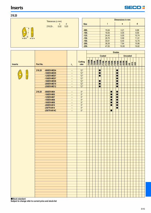
218.20 -080ER-ME04 – 12� [ [-100ER-ME05 – 12� [ [-125ER-ME07 – 12� [ [-150ER-ME07 – 12� [-160ER-ME08 – 12� [ [-200ER-ME10 – 12� [ [-250ER-ME12 – 12� [ [
218.20 -080ER-M04 – 0� [ [-100ER-M05 – 0� [ [-125ER-M07 – 0� [ [-150ER-M08 – 0� [ [-160ER-M08 – 0� [ [-200ER-M10 – 0� [ [-250TR-M14 – 0� [-250TR-M14C – 0� [
218.20
Tolerances (± mm)s d
218.20-.. 0,02 0,03Size
Dimensions in mm
l s d
-080. 15,64 3,21 6,88-100. 19,55 4,05 8,59-125. 24,43 5,05 10,74-150. 28,70 5,99 11,91-160. 30,61 6,40 12,70-200. 38,26 7,94 15,86-250. 47,83 10,00 19,82
[Stock standardSubject to change refer to current price and stock-list
Milling_090109.book Page 515 Friday, January 9, 2009 12:56 PM

Inserts
516
Inserts Part No.
Cutting
rake
Grades
Coated Uncoated
T1
50M
T2
00M
T2
5M
T2
50M
T3
50M
F1
5M
F1
7M
F2
0M
F2
5M
F3
0M
F4
0M
S1
0M
S2
5M
S6
0M
HX
H1
5
H2
5
219.19 -080-MD03 0� [-100-MD04 0� [-120-MD05 0� [-160-MD07 0� [-200-MD08 0� [-250-MD09 0� [-320-MD10 0� [
219.19 -080P-M02 0� [-100P-M03 0� [-120P-M04 0� [-160P-M05 0� [-200P-M06 0� [-250P-M07 0� [-320P-M08 0� [
219.19
Tolerances (mm)D
219.19-... +0/ -0,02s
219.19-... +0,005/ -0,010
Size
Dimensions in mm
D s
080 8,0 2,0100 10,0 2,5120 12,0 2,5160 16,0 3,0200 20,0 3,0250 25,0 4,0320 32,0 5,0
[Stock standardSubject to change refer to current price and stock-list
Milling_090109.book Page 516 Friday, January 9, 2009 12:56 PM

Inserts
517
Inserts Part No. B
Cutting
rake
Grades
Coated Uncoated
MK
15
00
MK
20
00
MK
30
00
MP
150
0
MP
250
0
MP
300
0
MH
10
00
MS
250
0
T2
5M
T3
50
M
F1
5M
F2
0M
F2
5M
F4
0M
S6
0M
HX
H1
5
H2
5
E07/E09
M10/M12
MD10
335.18 -1005-E07 0,5 20� [-1305-E08 0,5 20� [-1606-E09 0,5 20� [
335.18 -1005T-M10 0,5 10� [ [ [ [ [ [ [-100508-M10 0,5 08� [-1305T-M11 0,5 10� [ [ [ [ [ [ [-130508-M11 0,5 08� [-1606T-M12 0,5 10� [ [ [-160608-M12 0,5 08� [
335.18 -1005ZZ-MD10 - 0� [
335.18
Tolerances (± mm)l s A
335.18-10 0,013 0,025 0,013335.18-13 0,025 0,025 0,013335.18-16 0,025 0,025 0,013
Size
Dimensions in mm
l s A
-1005 10 5,4 10-1305 12,7 5,4 10-1606 16 6,4 12-1005ZZ 10 5,4 10
[Stock standardSubject to change refer to current price and stock-list
Milling_090109.book Page 517 Friday, January 9, 2009 12:56 PM

Inserts
518
Inserts Part No.
Cutting
rake
Grades
Coated Uncoated
MK
15
00
MK
20
00
MK
30
00
MP
150
0
MP
250
0
MP
300
0
MH
10
00
MS
250
0
T2
5M
T3
50
M
F1
5M
F2
0M
F2
5M
F4
0M
S6
0M
HX
H1
5
H2
5
E07
M08
MD09
335.19 -1205-E07 24� [
335.19 -1205-M08 15� [ [ [
335.19 -1205T-MD09 15� [ [
335.19
Tolerances (± mm)l s
335.19... 0,013 0,010Size
Dimensions in mm
l s
-1205. 12,7 5,4
[Stock standardSubject to change refer to current price and stock-list
Milling_090109.book Page 518 Friday, January 9, 2009 12:56 PM
Cermet
519
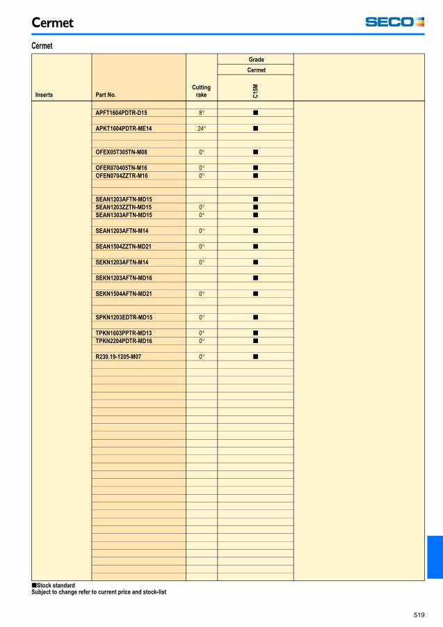
Cermet
Inserts Part No.
Cutting
rake
Grade
Cermet
C1
5M
APFT1604PDTR-D15 8� [
APKT1604PDTR-ME14 24� [
OFEX05T305TN-M08 0� [
OFER070405TN-M16 0� [OFEN0704ZZTR-M16 0� [
SEAN1203AFTN-MD15 [SEAN1203ZZTN-MD15 0� [SEAN1303AFTN-MD15 0� [
SEAN1203AFTN-M14 0� [
SEAN1504ZZTN-MD21 0� [
SEKN1203AFTN-M14 0� [
SEKN1203AFTN-MD16 [
SEKN1504AFTN-MD21 0� [
SPKN1203EDTR-MD15 0� [
TPKN1603PPTR-MD13 0� [TPKN2204PDTR-MD16 0� [
R230.19-1205-M07 0� [
Cermet
[Stock standardSubject to change refer to current price and stock-list
Milling_090109.book Page 519 Friday, January 9, 2009 12:56 PM

Secomax, - PCD inserts
520
Secomax, - PCD inserts
Inserts Part No.
Cutting
rake
Grades
PC
D2
0
OFEN 070405FN-M09 0� [
Inserts Part No.
Cutting
rake
Grades
PC
D20
OFEX 05T305FN-M05 0� [
OFEN
Tolerances (± mm)l s
OFEN 0,025 0,025Size
Dimensions in mm
l s B ap1 ap2
07 17,95 4,76 1,7 3,5 –
OFEX
Tolerances (± mm)l s
OFEX 0,025 0,025Size
Dimensions in mm
l s B ap1 ap2
05 12,79 3,97 1,5 2,6 –
[Stock standardSubject to change refer to current price and stock-list
Milling_090109.book Page 520 Friday, January 9, 2009 12:56 PM
Secomax, - PCD inserts
521
Inserts Part No.
Cutting
rake
Grades
PC
D2
0
PC
D3
0M
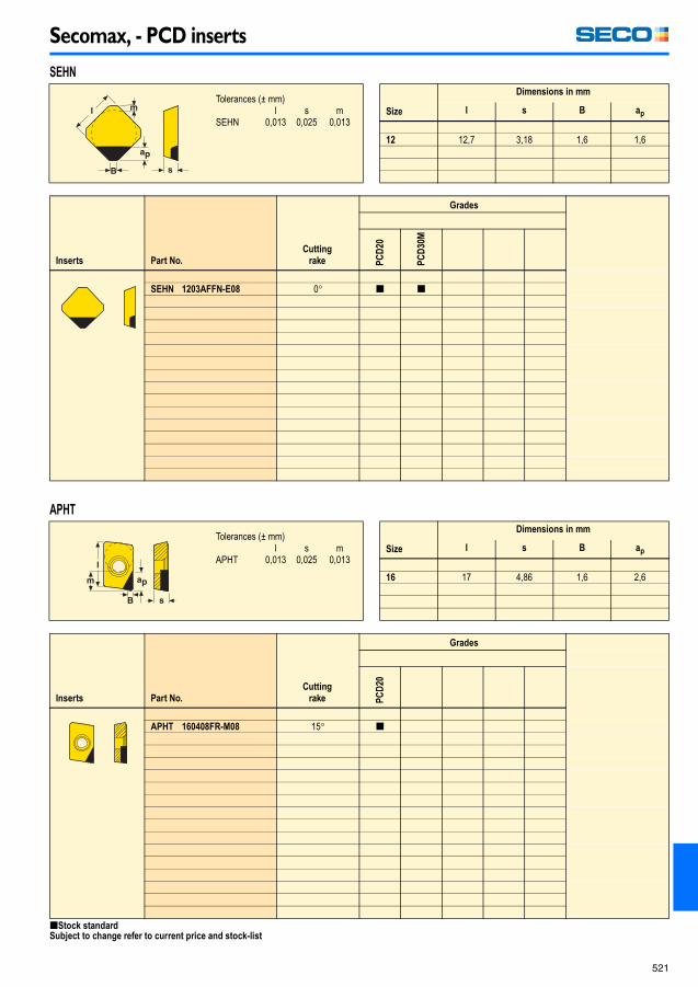
SEHN 1203AFFN-E08 0� [ [
Inserts Part No.
Cutting
rake
Grades
PC
D20
APHT 160408FR-M08 15� [
SEHN
Tolerances (± mm)l s m
SEHN 0,013 0,025 0,013Size
Dimensions in mm
l s B ap
12 12,7 3,18 1,6 1,6
APHT
Tolerances (± mm)l s m
APHT 0,013 0,025 0,013Size
Dimensions in mm
l s B ap
16 17 4,86 1,6 2,6
[Stock standardSubject to change refer to current price and stock-list
Milling_090109.book Page 521 Friday, January 9, 2009 12:56 PM

Secomax, - PCD inserts
522
Inserts Part No.
Cutting
rake
Grades
PC
D2
0
XCHX 13T304FR-M06 15� [
Inserts Part No.
Cutting
rake
Grades
PC
D2
0
PC
D0
5
PC
D3
0
XOEX 060204FR 8� [
XOEX 090304FR 8� [ [09030FR-ZZ 8� [
XOEX 120404FR 15� [ [120404FR-L2 14� [
XCHX
Tolerances (± mm)l s m
XCHX 0,013 0,025 0,013Size
Dimensions in mm
l s B ap
13 14 4,37 0,8 3,2
XOEX
Tolerances (± mm)l s m
XOEX06 0,03 0,13 0,025XOEX09 0,05 0,25 0,25XOEX12 0,05 0,25 0,25
Size
Dimensions in mm
l s B ap
06..FR 6,94 2,45 1,5 2,509..FR 10,75 3,65 1,45 409..ZZ 10,75 3,65 2 3,512..FR 13,88 5,03 1,5 412..FR-L2 13,7
[Stock standardSubject to change refer to current price and stock-list
Milling_090109.book Page 522 Friday, January 9, 2009 12:56 PM

Secomax, - PCD inserts
523
Inserts Part No.
Cutting
rake
Grades
PC
D2
0
PC
D0
5
SEEX 09T3AFFN-L1 0º [ [
SEEX09
Tolerances (± mm)l s m
SEEX 0,025 0,025 0,025Size
Dimensions in mm
l s B ap
09T3 9,525 3,97 1,5 1,6
[Stock standard
Subject to change refer to current price and stock-list
Milling_090109.book Page 523 Friday, January 9, 2009 12:56 PM

Secomax, - PCBN inserts
524
Secomax, - PCBN inserts
Inserts Part No.
Cutting
rake
Grades
CB
N1
0
CB
N1
00
CB
N10
0P
CB
N1
50
CB
N2
00
CB
N3
00
CB
N30
0P
CB
N05
0C
CB
N40
0C
RNMN/RNGN
E = HonedS = Chamfered and honed
Solid
RNGN 090300E25 0� [060300E 0� [ [ [060300S-01020 0� [ [090300E 0� [ [ [090300S-01020 0� [ [
RNMN 060300S 0� [ [090300E 0� [ [090300S 0� [ [ [
RNGN 060300S-01525 0� [090300S-01525 0� [
Inserts Part No.
Cutting
rake
Grades
CB
N10
CB
N10
0
CB
N1
00P
CB
N15
0
CB
N20
0
CB
N30
0
CB
N3
00P
CB
N1
60C
RNGN-LF
S = Chamfered and honed
LF = Complete top layer
RNGN 060300S-LF 0� [ [090300S-LF 0� [ [
RNGN 060300S-01525-LF 0� [ [090300S-01525-LF 0� [ [
RN.N06/09
Tolerances (± mm)D s
RNMN06 0,05 0,13RNGN06 0,025 0,13RNMN09 0,05 0,13RNGN09 0,025 0,13
Size
Dimensions in mm
D s
RNMN06 6,350 3,18RNGN06 6,350 3,18RNMN09 9,525 3,18RNGN09 9,525 3,18
RNGN-LF 06/09
Tolerances (± mm)D s
0,025 0,13Size
Dimensions in mm
D s
06 6,350 3,1809 9,525 3,18
[Stock standardSubject to change refer to current price and stock-list
Milling_090109.book Page 524 Friday, January 9, 2009 12:56 PM

Secomax, - PCBN inserts
525
Inserts Part No. re
Cutting
rake
Grades
CB
N1
0
CB
N1
00
CB
N1
50
CB
N3
00
CB
N2
00
CB
N10
0P
CB
N30
0P
CB
N05
0C
CB
N40
0C
SNMN 060308E 0,8 0� [ [ [060308S 0,8 0� [
SNMN 090308E 0,8 0� [ [ [090308S 0,8 0� [ [ [
SNMN 090312E 1,2 0� [ [090312S 1,2 0� [ [
SNMN 090316S 1,6 0� [
SNEX 120312ZZ 1,2 0� [
SNGN 060308S 0,8 0� [
SNGN 090304E 0,4 0� [090304S-01020 0,4 0� [090308E 0,8 0� [ [090308S-01020 0,8 0� [ [090312S-01020 1,2 0� [ [090316S 1,6 0� [
SNGN 090308S-01525 0,8 0� [
SN..06/09/SNEX12
Tolerances (± mm)l s m
SNMN 0,05 0,013 0,08SNEX 0,025 0,025 0,025SNGN 0,025 0,013 0,025
Size
Dimensions in mm
l s
09 9,525 3,1812 12,7 3,18
[Stock standardSubject to change refer to current price and stock-list
Milling_090109.book Page 525 Friday, January 9, 2009 12:56 PM
Secomax, - PCBN inserts
526
Inserts Part No. B
Cutting
rake
Grades
CB
N1
0
CB
N1
00
CB
N10
0P
CB
N1
50
CB
N2
00
CB
N3
00
CB
N30
0P
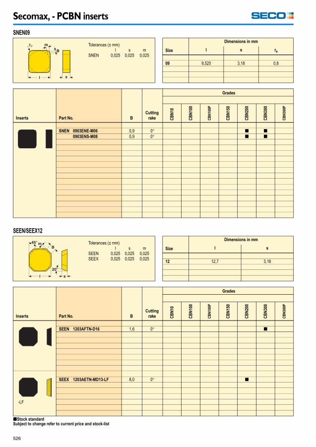
SNEN 0903ENE-M06 0,9 0� [ [0903ENS-M08 0,9 0� [ [
Inserts Part No. B
Cutting
rake
Grades
CB
N10
CB
N10
0
CB
N1
00P
CB
N15
0
CB
N20
0
CB
N30
0
CB
N3
00P
SEEN 1203AFTN-D16 1,6 0� [
-LF
SEEX 1203AETN-MD13-LF 8,0 0� [
SNEN09
Tolerances (± mm)l s m
SNEN 0,025 0,025 0,025Size
Dimensions in mm
l s re
09 9,525 3,18 0,8
SEEN/SEEX12
Tolerances (± mm)l s m
SEEN 0,025 0,025 0,025SEEX 0,025 0,025 0,025
Size
Dimensions in mm
l s
12 12,7 3,18
[Stock standardSubject to change refer to current price and stock-list
Milling_090109.book Page 526 Friday, January 9, 2009 12:56 PM

Secomax, - PCBN inserts
527
Inserts Part No.
Cutting
rake
Grades
CB
N1
0
CB
N1
00
CB
N10
0P
CB
N1
50
CB
N2
00
CB
N3
00
CB
N30
0P
TNGN 1103PNE 0� [1103PNS 0� [1103PRS 0� [
TNGN 1604PNE 0� [1604PNS 0� [1604PRS 0� [
Inserts Part No. B
Cutting
rake
Grades
CB
N10
CB
N10
0
CB
N1
00P
CB
N15
0
CB
N20
0
CB
N30
0
CB
N3
00P
-LF
OFEN 070405TN-MD16-LF 1,6 0� [
TNGN
Tolerances (± mm)d s m
TNGN 0,025 0,13 0,025Size
Dimensions in mm
~ l d s
16 16,5 11,857 4,76
OFEN
Tolerances (± mm)l
OFEN 0,025Size
Dimensions in mm
d l s
07 17,96 17,96 4,76
[Stock standardSubject to change refer to current price and stock-list
Milling_090109.book Page 527 Friday, January 9, 2009 12:56 PM

Secomax, - PCBN inserts
528
Inserts Part No. r�
Cutting
rake
Grades
CB
N1
0
CB
N1
00
CB
N10
0P
CB
N1
50
CB
N2
00
CB
N3
00
CB
N30
0P
218.19 -100T-MD08-LF 0,8 [
Inserts Part No. B
Cutting
rake
Grades
CB
N10
CB
N10
0
CB
N1
00P
CB
N15
0
CB
N20
0
CB
N30
0
CB
N3
00P
ZZTN
SEEX 09T3AFTN-D09-LF 1,25 0� [
SEEX 1204AFTN-D16-LF 1,57 0� [
SEEX 1204ZZTN-D16-LF – 0� [
218.19-100T
Tolerances (± mm)l R s
218.19 0,01 0,01 0,013-0,07Size
Dimensions in mm
d s R
100T 7,00 2,78 10
SEEX09/12
Tolerances (± mm)l s m
SEEX 0,025 0,025 0,025Size
Dimensions in mm
l s
09T3 9,525 3,971204 12,7 4,76
[Stock standardSubject to change refer to current price and stock-list
Milling_090109.book Page 528 Friday, January 9, 2009 12:56 PM

Thread milling inserts
529
Thread milling inserts
Inserts Part No.
Grades
Coated Uncoated
CP
200
CP
500
F3
0M
H1
5
For internal threading
13NM S1.0ISO* [S1.5ISO* [S2.0ISO* [S16UN* [S20UN* [S24UN* [
For ext. and int. threading
13XM S14W* [S19W* [
13NMS/XMS
Tolerances (± mm)d l s
13... 0,012 0,012 0,025Size
Dimensions in mm
l d s
13... 13 7 2,5
[Stock standard * Single sided inserts.Subject to change refer to current price and stock-list
Milling_090109.book Page 529 Friday, January 9, 2009 12:56 PM

Thread milling inserts
530
Inserts Part No.
Grades
Coated Uncoated
CP
200
CP
500
F3
0M
H1
5
For external threading
396.19 -4003.0E1.0ISO [-4003.0E1.5ISO [-4003.0E2.0ISO [-4003.0E12UN [-4003.0E14UN [-4003.0E16UN [-4003.0E18UN [
For internal threading
396.19 -4003.0N1.0ISO [ [-4003.0N1.5ISO [ [-4003.0N2.0ISO [ [-4003.0N2.5ISO [-4003.0N3.0ISO [-4003.0N10UN [-4003.0N12UN [ [-4003.0N14UN [ [-4003.0N16UN [ [-4003.0N18UN [-4003.0N20UN [-4003.0N8UN [-4003.0N9UN [
For ext. and int. threading
396.19 -4003.0X11W [-4003.0X12W [-4003.0X14W [-4003.0X16W [
396.19-4003
Tolerances (± mm)d l s
4003... 0,012 0,007 0,05Size
Dimensions in mm
l d s
4003 40,0 – 3,5
[Stock standardSubject to change refer to current price and stock-list
Milling_090109.book Page 530 Friday, January 9, 2009 12:56 PM

Thread milling inserts
531
Inserts Part No.
Grades
Coated Uncoated
CP
200
CP
500
F3
0M
H1
5
For internal threading
396.19 -4005.0N3.5ISO [-4005.0N4.0ISO [-4005.0N4.5ISO [-4005.0N5.0ISO [-4005.0N5.5ISO [-4005.0N6.0ISO [-4005.0N4.5UN [-4005.0N4UN [-4005.0N5UN [-4005.0N6UN [-4005.0N7UN [
For ext. and int. threading
396.19 -4005.0X8W [
R396.19 -4005.0X8NPT [-4003.0X11.5NPT [-4003.0X11.5NPTF [-4003.0X14NPT [-4003.0X14NPTF [-4003.0X11BSPT [-4003.0X14BSPT [
Non-cutting blank
396.19 -4003XX [-4005XX [
396.19-4003/4005
Tolerances (± mm)d l s
4003... 0,012 0,007 0,054005... 0,012 0,015 0,05
Size
Dimensions in mm
l d s
4003 40,0 – 3,54005 40,0 – 5,0
[Stock standardSubject to change refer to current price and stock-list
Milling_090109.book Page 531 Friday, January 9, 2009 12:56 PM
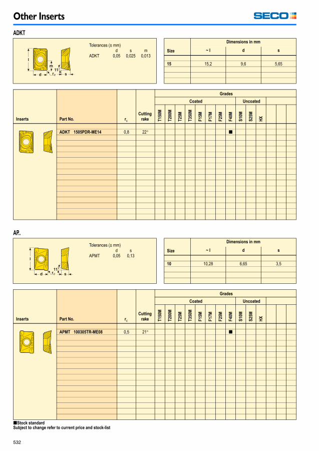
Other Inserts
532
Other Inserts
Inserts Part No. r�
Cutting
rake
Grades
Coated Uncoated
T1
50
M
T2
00
M
T2
5M
T3
50
M
F1
5M
F1
7M
F2
5M
F4
0M
S1
0M
S2
5M
HX
ADKT 1505PDR-ME14 0,8 22� [
Inserts Part No. r�
Cutting
rake
Grades
Coated Uncoated
T1
50
M
T2
00
M
T2
5M
T3
50
M
F1
5M
F1
7M
F2
5M
F4
0M
S1
0M
S2
5M
HX
APMT 100305TR-ME08 0,5 21� [
ADKT
Tolerances (± mm)d s m
ADKT 0,05 0,025 0,013Size
Dimensions in mm
~ l d s
15 15,2 9,6 5,65
AP..
Tolerances (± mm)d s
APMT 0,05 0,13Size
Dimensions in mm
~ l d s
10 10,28 6,65 3,5
[Stock standardSubject to change refer to current price and stock-list
Milling_090109.book Page 532 Friday, January 9, 2009 12:56 PM

Other Inserts
533
Inserts Part No. B
Cutting
rake
Grades
Coated Uncoated
T1
50
M
T2
00
M
T2
5M
T3
50
M
F1
5M
F1
7M
F2
5M
F4
0M
S1
0M
S2
5M
HX
LNJN 2205DDR-MD25 2,4 0� [
LNJN
Tolerances (± mm)d s m
LNJN22 0,08 0,025 0,007LNJN30 0,10 0,025 0,007
Size
Dimensions in mm
~ l s a
22 22,0 5,0 12,030 30,0 7,0 20,0
[Stock standard
Subject to change refer to current price and stock-list
Milling_090109.book Page 533 Friday, January 9, 2009 12:56 PM

Other Inserts
534
Inserts Part No.
Cutting
rake
Grades
Coated Uncoated
T1
50
M
T2
00
M
T3
50
M
T2
5M
F1
5M
F1
7M
F2
5M
F4
0M
S1
0M
S2
5M
HX
RPHT 0803M0T-M06 25� [
RPHT 10T3M0T-M08 25� [
Inserts Part No. B
Cutting
rake
Grades
Coated Uncoated
T1
50
M
T2
00
M
T2
5M
T3
50
M
F1
5M
F1
7M
F2
5M
F4
0M
S1
0M
S2
5M
HX
SBAN
SBAN 1203ZZ 0,67 0� [
RPHT
Tolerances (± mm)D s
RPHT 0,013 0,025Size
Dimensions in mm
D s
08 8,0 3,1810 10,0 3,97
SBAN
Tolerances (± mm)l s m
SBAN 0,025 0,025 0,025SBEX 0,025 0,025 0,025
Size
Dimensions in mm
l s b
1203 12,7 3,18 0,71204 12,65 4,76 0,8
[Stock standardSubject to change refer to current price and stock-list
Milling_090109.book Page 534 Friday, January 9, 2009 12:56 PM

Other Inserts
535
Inserts Part No. B
Cutting
rake
Grades
Coated Uncoated
T1
50
M
T2
00
M
T2
5M
T3
50
M
F1
5M
F1
7M
F2
5M
F4
0M
S1
0M
S2
5M
HX
SEMN 2506AFTN-M20 5,8 0� [
SEMN 3107AFTN-M25 6,1 0� [
SEMN
Tolerances (± mm)l s m
SEMN25 0,13 0,13 0,18SEMN31 0,15 0,13 0,20
Size
Dimensions in mm
l s
25 25,4 6,3531 31,75 7,94
[Stock standardSubject to change refer to current price and stock-list
Milling_090109.book Page 535 Friday, January 9, 2009 12:56 PM

Other Inserts
536
Inserts Part No. B
Cutting
rake
Grades
Coated Uncoated
MK
15
00
MK
20
00
MK
30
00
MP
250
0
MH
10
00
T1
50
M
T2
00
M
T2
5M
T3
50
M
F1
5M
F1
7M
F2
5M
F4
0M
S1
0M
S2
5M
HX
E08
M10
SNKF 1204ENEN-E08 0,9 17� [
SNKN 1204EN-M10 0,9 0� [ [ [
SNKF/SNKN
Tolerances (± mm)l s m
SNK. 0,08 0,025 0,05Size
Dimensions in mm
l s
12 12,7 4,76
[Stock standardSubject to change refer to current price and stock-list
Milling_090109.book Page 536 Friday, January 9, 2009 12:56 PM
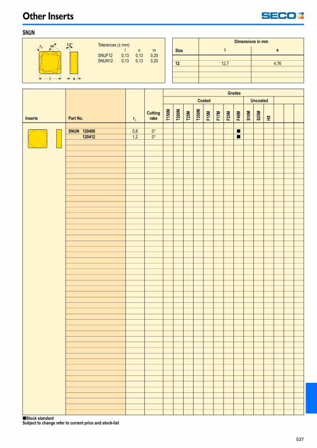
Other Inserts
537
Inserts Part No. r�
Cutting
rake
Grades
Coated Uncoated
T1
50
M
T2
00
M
T2
5M
T3
50
M
F1
5M
F1
7M
F2
5M
F4
0M
S1
0M
S2
5M
HX
SNUN 120408 0,8 0� [120412 1,2 0� [
SNUN
Tolerances (± mm)l s m
SNUF12 0,13 0,13 0,20SNUN12 0,13 0,13 0,20
Size
Dimensions in mm
l s
12 12,7 4,76
[Stock standardSubject to change refer to current price and stock-list
Milling_090109.book Page 537 Friday, January 9, 2009 12:56 PM

Other Inserts
538
Inserts Part No. B
Cutting
rake
Grades
Coated Uncoated
T1
50
M
T2
00
M
T2
5M
T3
50
M
F1
5M
F1
7M
F2
5M
F4
0M
S1
0M
S2
5M
HX
SPER
SPFN
SPER 1904ZETR-M17 1,0 17� [
SPFN 1904ZETR-MD20 1,0 0� [
Inserts Part No. r�
Cutting
rake
Grades
Coated Uncoated
T1
50
M
T2
00
M
T2
5M
T3
50
M
F1
5M
F1
7M
F2
5M
F4
0M
S1
0M
S2
5M
HX
M17
SPER 1904ZZTR-M17 1,6 17� [
SPER/SPFN
Tolerances (± mm)l s m
SPER 0,025 0,025 0,025SPFN 0,02 0,025 0,007
Size
Dimensions in mm
l d
1904 19,05 4,76
SPER-ZZ
Tolerances (± mm)l s m
SPER 0,025 0,025 0,025SPFN 0,025 0,025 0,01
Size
Dimensions in mm
l s B
1904 19,05 4,76 12
[Stock standardSubject to change refer to current price and stock-list
Milling_090109.book Page 538 Friday, January 9, 2009 12:56 PM

Other Inserts
539
Inserts Part No. B
Cutting
rake
Grades
Coated Uncoated
T1
50
M
T2
00
M
T2
5M
T3
50
M
F1
5M
F2
5M
F3
0M
F4
0M
S1
0M
S2
5M
HX
M13-MD15
ME12-ME14
1203ZZ/1504ZZ
SPKN 1203EDR-M13 1,4 0� [ [1203EDTR-MD14 1,4 0� [ [ [1203EDTL-MD14 1,4 0� [
SPKN 1203ZZR-M13 - 0� [
SPKR 1203EDTR-ME12 1,2 20� [
SPMN 1203EDR-MD13 1,4 0� [
SPKR 1504EDTR-ME14 1,3 20� [
SPKN 1504ZZR-M15 - 0� [1504ZZL-M15 - 0� [1504EDR-M15 1,4 0� [1504EDR-MD15 1,4 0� [1504EDTR-MD17 1,4 0� [
SPKN/SPKR
Tolerances (± mm)l s m
SPK.12 0,08 0,025 0,013SPKN15 0,10 0,025 0,013SPMN 0,08 0,13 0,13
Size
Dimensions in mm
l s
1203 12,7 3,181504 15,875 4,76
[Stock standardSubject to change refer to current price and stock-list
Milling_090109.book Page 539 Friday, January 9, 2009 12:56 PM

Other Inserts
540
Inserts Part No. r�
Cutting
rake
Grades
Coated Uncoated
T1
50
M
T2
00
M
T2
5M
T3
50
M
F1
5M
F1
7M
F2
5M
F4
0M
S1
0M
S2
5M
HX
SPUN 120308T 0,8 0� [120312T 1,2 0� [
SPUN
Tolerances (± mm)d s m
SPUN 0,13 0,13 0,20Size
Dimensions in mm
l s
12 12,7 3,18
[Stock standardSubject to change refer to current price and stock-list
Milling_090109.book Page 540 Friday, January 9, 2009 12:56 PM
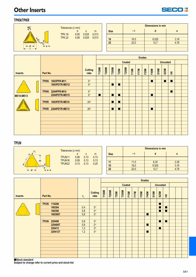
Other Inserts
541
Inserts Part No.
Cutting
rake
Grades
Coated Uncoated
T1
50
M
T2
00
M
T3
50
M
T2
5M
T2
50
M
F1
5M
F1
7M
F2
5M
F4
0M
S1
0M
S2
5M
HX
ME10-ME13
TPKN 1603PPR-M11 0� [ [ [1603PDTR-MD12 0� [ [
TPKN 2204PPR-M14 0� [2204PDTR-MD15 0� [ [ [ [
TPKR 1603PDTR-ME10 24� [ [
TPKR 2204PDTR-ME13 20� [ [ [
Inserts Part No. r�
Cutting
rake
Grades
Coated Uncoated
T1
50
M
T2
00
M
T2
5M
T3
50
M
F1
5M
F1
7M
F2
5M
F4
0M
S1
0M
S2
5M
HX
TPUN 110208 [160304 0,4 0� [ [160308 0,8 0� [ [160308T 0,8 0� [
TPUN 220408 0,8 0� [ [220408T 0,8 0� [220412 1,2 0� [220412T 1,2 0� [
TPKN/TPKR
Tolerances (± mm)d s m
TPK.16 0,05 0,025 0,013TPK.22 0,08 0,025 0,013
Size
Dimensions in mm
~ l d s
16 16,5 9,525 3,1822 22,0 12,7 4,76
TPUN
Tolerances (± mm)d s m
TPUN11 0,08 0,13 0,13TPUN16 0,08 0,13 0,13TPUN22 0,13 0,13 0,20
Size
Dimensions in mm
~ l d s
11 11,0 6,35 2,3816 16,5 9.525 3,1822 22,0 12,7 4,76
[Stock standardSubject to change refer to current price and stock-list
Milling_090109.book Page 541 Friday, January 9, 2009 12:56 PM
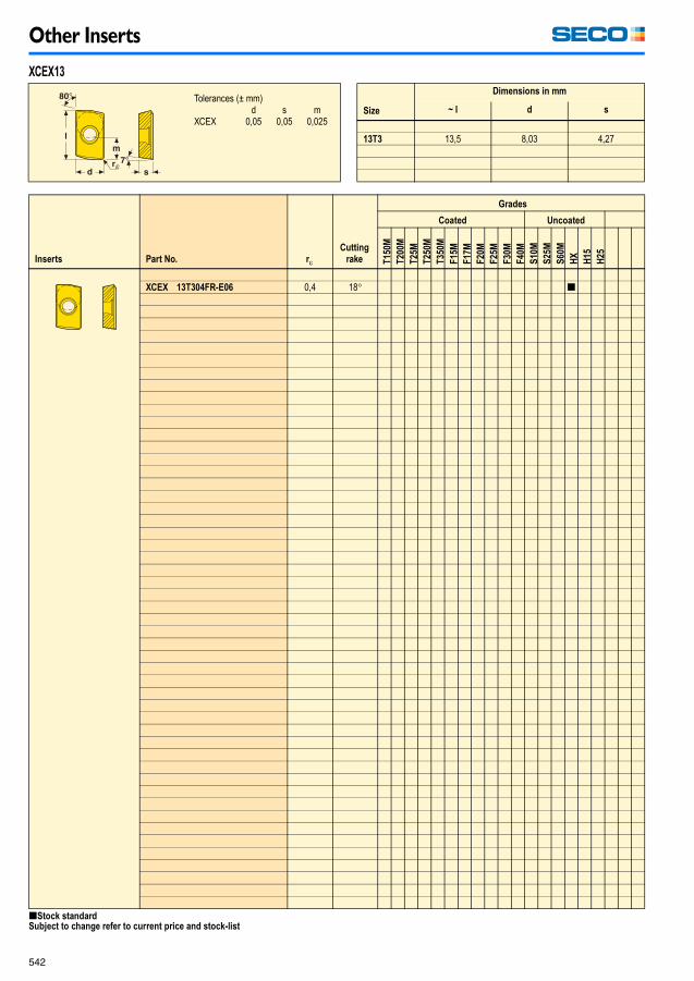
Other Inserts
542
Inserts Part No. r�
Cutting
rake
Grades
Coated Uncoated
T1
50
M
T2
00
M
T2
5M
T2
50
M
T3
50
M
F1
5M
F1
7M
F2
0M
F2
5M
F3
0M
F4
0M
S1
0M
S2
5M
S6
0M
HX
H1
5
H2
5
XCEX 13T304FR-E06 0,4 18� [
XCEX13
Tolerances (± mm)d s m
XCEX 0,05 0,05 0,025Size
Dimensions in mm
~ l d s
13T3 13,5 8,03 4,27
[Stock standardSubject to change refer to current price and stock-list
Milling_090109.book Page 542 Friday, January 9, 2009 12:56 PM

Other Inserts
543
Inserts Part No. r�
Cut-
ting
rake
Grades
Coated Uncoated
MK
15
00
MK
20
00
MK
30
00
MP
15
00
MP
25
00
MP
30
00
MH
10
00
MS
25
00
T25
M
T35
0M
F15
M
F20
M
F25
M
F30
M
F40
M
S60
M
HX
H1
5
H2
5
XCKX 13T304R-ME10 0,4 24� [ [ [13T308R-ME10 0,8 24� [ [ [13T316R-ME10 1,6 24� [
Inserts Part No. r�
Cut-
ting
rake
Grades
Coated Uncoated
MK
150
0
MK
200
0
MK
300
0
MP
15
00
MP
25
00
MP
30
00
MH
100
0
MS
25
00
T2
5M
T3
50
M
F1
5M
F2
0M
F2
5M
F4
0M
S6
0M
HX
H1
5
H2
5
XCMX 13T308TR-M11 0,8 15� [ [ [13T320TR-M11 2,0 15� [13T330TR-M11 3,0 15� [
XCKX13
Tolerances (± mm)d s m
XCKX 0,05 0,025 0,013Size
Dimensions in mm
~ l d s
13T304R 14,7 7,922 5,0313T308R 14,6 7,922 5,0313T316R 14,3 7,922 5,0313T320R 14,1 7,922 5,0313T330R 14,1 7,922 5,03
XCMX13
Tolerances (± mm)d s m
XCMX 0,05 0,13 0,08Size
Dimensions in mm
~ l d s
13T308 14,4 8,03 4,3713T320 14,0 8,03 4,3713T330 13,6 8,03 4,37
[Stock standardSubject to change refer to current price and stock-listWhen using inserts with corner radius > 2 mm, the cutter body must be modified.
Milling_090109.book Page 543 Friday, January 9, 2009 12:56 PM

Milling
544
Milling
Milling
Milling_090109.book Page 544 Friday, January 9, 2009 12:56 PM

Milling – PCBN
545
Milling – PCBN
Suitable workpiece materials
• Secomax CBN10/100 and CBN150 inserts are suitablefor finishing in hard steel (52-63 HRc).
• CBN200 inserts are suitable for finishing and roughingin hard steel (52-63HRc) and finishing and roughingin pearlitic cast iron with a free ferrite content of lessthan 5%
Secomax CBN300 inserts are suitable for:• Roughing in hard steel (52-63 HRc).• Finishing and roughing in pearlitic cast iron with a free
ferrite content of less than 5%.Note: When milling with PCBN conventional milling should be used.Use inserts with protection chamfer (S) for best tool life.
Face milling cutter type R217/220.70
Cutter especially developed for CBN inserts, 2 insertsizes. Maximum cutting depth 3 mm Dc = 20-63 mmand maximum cutting depth 4,5 mm Dc = 63-200 mm(Dc = 125-200 mm fitted with wiper insert).
Inserts for finishing RNGN060300E (E = honed)RNGN/RNMN090300E
Inserts for roughing RNGN/RNMN060300S(S = chamfered and honed)RNGN/RNMN090300S
Wiper insert SNEX120312ZZ
The relation between cutting depth and number of usablecutting edges (per side).
Square shoulder and slot milling cutter type R220.68
Cutter especially developed for CBN inserts,maximum cutting depth 8,0 mm D = 63-200 mm.(D = 125-200 mm fitted with wiper insert).
Inserts for finishing SNEN0903ENE-M06(E = honed)SNMN090308ESNMN090312E
Inserts for roughing SNEN0903ENS-M08(S = chamfered and honed)SNMN090308SSNMN090312SSNMN090316S
Wiper insert SNEX120312ZZ
Square shoulder and slot milling cutter type R220.68
Insert with corner chamferfor finishing operations TNGN1604PNE
Insert with corner chamferfor roughing operations TNGN1604PNS
Cutter especially developed for CBNinserts. D = 63-160 mm Insert with corner radius
for roughing operations TNGN1604PRS
D.O.C
ap (mm)
RN..
060300
RN..
090300
D.O.C
ap (mm)
RN..
060300
RNMN
090300
0,1 20 24 1,2 5 70,15 16 20 1,5 5 60,2 14 17 1,8 4 50,25 12 15 2,0 4 50,3 11 14 2,5 3 40,4 10 12 3,0 3 40,5 8 10 3,5 – 40,8 7 8 4,0 – 31,0 6 7 4,5 – –
Programme
Milling_090109_14.fm Page 545 Tuesday, January 27, 2009 2:05 PM

Milling – PCBN
546
Inserts for standard milling cutters
For roughingSEEX09T3AFTN-D09-LF
SEEX1204AFTN-D16-LF
QuattroMill R220.53 milling cutter
For roughingOFEN070405TN-MD16
Octomill R220.43Face milling cutter
For roughingSEEN1203AFTN-D16
R220.13 Face milling cutter
For finishingSEEX1203AETN-MD13
R220.30 Face milling cutter
Wiper insert for high quality surface finishSEEX1204ZZTN-D16-LF
Cutting data
• Cutting speed recommendations are in the cutting datatable.
• Feed rate recommendations are in the cutting data table.• Formulae for cutting data calculation are on page 557.
Troubleshooting
Breakage
• Do not use worn anvils.• Do not use worn wedges.• Clean seats and inserts.
Edge chipping
• Use inserts with chamferedcutting edges.
• Increase the system rigidity.• Change the feed rate.
Cutting edgebreakage • Reduce the cutting edge load (i.e)
the depth of cut or feed rate).• Increase the insert corner radius
(consider using round inserts).• Use inserts with chamfered
cutting edges.• Change the cutting speed.
Rake face flaking while in continuous cut
• Reduce the feed rate.• Use inserts with chamfered cutting
edges.
Rapid flank wear
• Increase the cutting speed.• Increase the feed rate.• Check if the ferrite content is within the
prescribed limits.
Rake face flaking when milling in irregular surfaces • Do not use coolant.
• Use chamfered inserts.• Change the feed rate.• Increase the cutting speed.
Notching
• Reduce the feed rate.• Increase the cutting speed.• Vary the depth of cut.• Use inserts with chamfered
cutting edges.
Milling_090109.book Page 546 Friday, January 9, 2009 12:56 PM
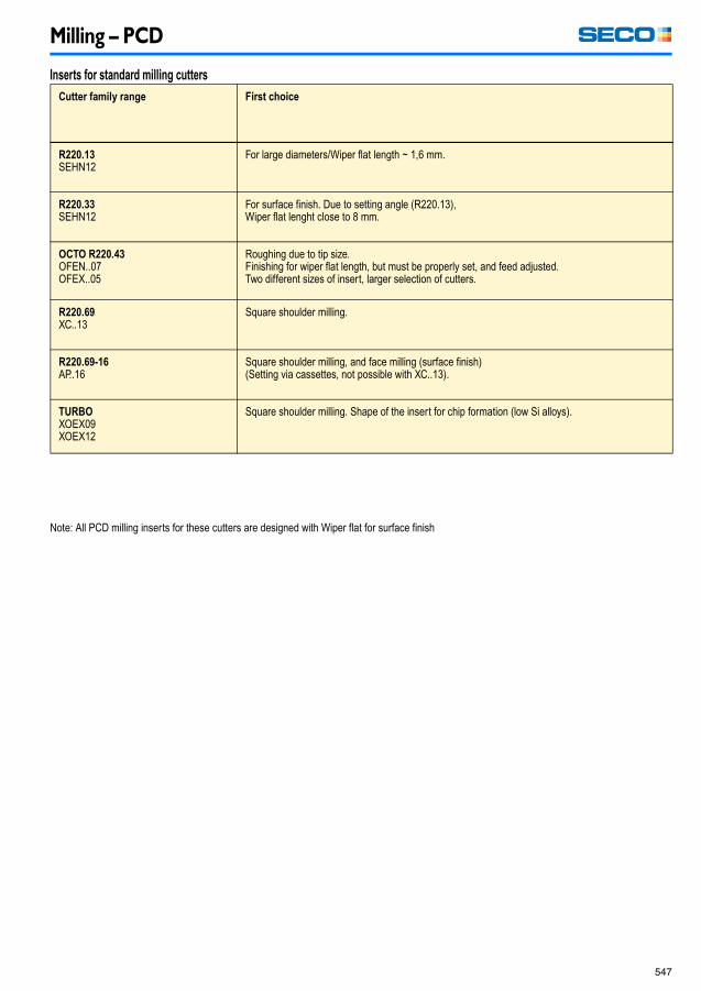
Milling – PCD
547
Milling – PCD
Inserts for standard milling cutters
Cutter family range First choice
R220.13SEHN12
For large diameters/Wiper flat length ~ 1,6 mm.
R220.33SEHN12
For surface finish. Due to setting angle (R220.13),Wiper flat lenght close to 8 mm.
OCTO R220.43OFEN..07OFEX..05
Roughing due to tip size.Finishing for wiper flat length, but must be properly set, and feed adjusted.Two different sizes of insert, larger selection of cutters.
R220.69XC..13
Square shoulder milling.
R220.69-16AP..16
Square shoulder milling, and face milling (surface finish)(Setting via cassettes, not possible with XC..13).
TURBOXOEX09XOEX12
Square shoulder milling. Shape of the insert for chip formation (low Si alloys).
Note: All PCD milling inserts for these cutters are designed with Wiper flat for surface finish
Milling_090109_14.fm Page 547 Tuesday, January 27, 2009 2:05 PM

Milling – PCD
548
Troubleshooting
Problem Possible cause Suggested actions
Rapid wear Wrong choice of grade • Change to coarser PCD grade
Presence of Fe/Ni/Co • Check material composition• Reduce cutting speed• Use coolant
Built-up edge High speed • Reduce cutting speed to reduce heat generation or use coolant
Incorrect cutting edgeselection
• Choose a sharper edge
Low speed • Increase speed to improve cutting action
Wrong choice of grade • Change to finer PCD grade
Edge chipping Poor rigidity • Minimize vibration• Check set-up, run-out• Change nose angle
Operating conditions • Review speeds and feeds
Wrong edge design(radius or honing)
• Increase nose radius or change to chamfer type• Add a honing or slight chamfer on the edge
High run-out • Check set-up
Wrong choice of grade • Change to a tougher grade(PCD10 � PCD20 � PCD30 � PCD30M � PCD05)
Edge breakage Wrong choice of grade • Change to a tougher grade(PCD10 � PCD20 � PCD30 � PCD30M � PCD05)
Poor surface finish Wrong choice of grade • Change to finer PCD grade
High feed speed • Check set-up
Poor set-up of Wiperinsert
• Check offset of Wiper / Other inserts
Flaking of workpiece Large depth of cut • Reduce depth of cut• Add entry chamfer on the component
Milling_090109.book Page 548 Friday, January 9, 2009 12:56 PM

Max RPM
549
Max RPM
Recommended RPM for all Seco cutters are shown on each catalogue page.Normally there is no need for balancing tools for RPM up to 10 000.However in some cases balancing is necessary, for instance when using heavy tools and toolholders in small machines
Over 10 000 RPM:We recommend balancing of tool and toolholders at least separately.Over 20 000 RPM:Both tool and toolholders must be balanced at least separately.Over 30 000 RPM:Tool and tool holders must be balanced as a unit.The max RPM in the tables should never be exceeded.
Milling_090109_14.fm Page 549 Tuesday, January 27, 2009 2:05 PM

Dynamomentic keys
550
Dynamomentic keys
The range of dynamomentic keys with fixed torque values are available in combinations of key grip/torque value for insert locking for most of the Seco milling products.By using a dynamomentic key you always ensure the correct tightening force when mounting the insert. The torque value is given in the spare part table for each cutter.Dynamomentic keys are calibrated according to ISO 6789.
Code key: T00-15P35T00 = Dynamomentic screw driver type for Torx Plus blade
T00T = Dynamomentic T-handle type for Torx Plus blade
H00T = Dynamomentic T-handle type for hexagonal blade
15P = Torx Plus size
35 = Torque value 3,5 Nm
Dynamomentic
key*
Replaceable
blade
Torque Plus
sizeTorque value
T00-06P05 T00-06P T06P 0,5 NmT00-07P09 T00-07P T07P 0,9 NmT00-08P12 T00-08P T08P 1,2 NmT00-09P12 T00-09P T09P 1,2 NmT00-09P20 T00-09P T09P 2,0 NmT00-10P20 T00-10P T10P 2,0 NmT00-10P30 T00-10P T10P 3,0 NmT00-15P20 T00-15P T15P 2,0 NmT00-15P30 T00-15P T15P 3,0 NmT00-15P35 T00-15P T15P 3,5 NmT00-15P50 T00-15P T15P 5,0 NmT00-20P50 T00-20P T20P 5,0 Nm
Dynamomentic
key*
Replaceable
blade
Torque Plus
size
Torque value
T00T-15P50 T00T-15P T15P 5,0 NmT00T-20P50 T00T-20P T20P 5,0 NmT00T-20P80 T00T-20P T20P 8,0 NmT00T-25P60 T00T-25P T25P 6,0 NmT00T-25P80 T00T-25P T25P 8,0 NmT00T-30P80 T00T-30P T30P 8,0 Nm
Dynamomentic
key*
Replaceable
blade
Hexagonal size Torque value
H00T-3050 H00T-3.0 3 mm 5,0 NmH00T-4050 H00T-4.0 4 mm 5,0 NmH00T-4060 H00T-4.0 4 mm 6,0 NmH00T-5080 H00T-5.0 5 mm 8,0 NmH00T-60100 H00T-6.0 6 mm 10,0 Nm
Please observe that blades are not interchangeable between screw driver type and T-handle type.Torx Plus® is a registered trade mark belonging to Camcar-Textron (USA)
*Including blade
Milling_090109.book Page 550 Friday, January 9, 2009 12:56 PM

Technical information
551
Technical information
Milling_090109_14.fm Page 551 Tuesday, January 27, 2009 2:05 PM

Ramping
552
Ramping
The milling cutter design and the clearance on the bottom side of thechosen insert determines the tool’s suitability for ramping.Maximum ramping angle and cutting depth recommendations for suitable tools are found in the tables below.Use the cutting speeds and feed rates recommended fornormal operations.
Cutter dia
Dc mm
Cutter dia
�Dc2 mm
ap
max
�max
217/220.29-025
5 10 2,5 90�7 12 2,5 13,5�10 15 2,5 8�15 20 2,5 5�
217/220.29-03
4 10 3 30�6 12 3 90�10 16 3 15,5�14 20 3 9,6�19 25 3 6,5�26 32 3 4,5�29 35 3 4�34 40 3 3�
217/220.29-035
8 15 3,5 22�9 16 3,5 17,5�13 20 3,5 10�18 25 3,5 6,5�28 35 3,5 4�
217/220.29-04
4 12 4 30�8 16 4 90�12 20 4 16,5�17 25 4 10�24 32 4 6,5�27 35 4 5,5�32 40 4 4,5�42 50 4 3�
217/220.29-056 16 5 30�10 20 5 90�15 25 5 17�22 32 5 10�25 35 5 8,5�30 40 5 6,5�32 42 5 6,3�40 50 5 4,5�
Cutter dia
Dc mm
Cutter dia
Dc2 mm
ap
max
�max
217/220.29-06
4 16 6 30º8 20 6 30º12 24 6 90º13 25 6 90º20 32 6 14,7º23 35 6 12º28 40 6 9,3º30 42 6 4,2º32 44 6 7,85º38 50 6 6,4º40 52 6 6º50 62 6 4,65º51 63 6 4,55º54 66 6 4,25º63 75 6 3,6º68 80 6 3,3º80 92 6 2,75º
100 112 6 2,15º125 137 6 1,7º
217/220.29-08
16 32 8 90º24 40 8 20º34 50 8 15,5º36 52 8 13º47 63 8 9,5º50 66 8 8,5º64 80 8 6º84 100 8 5º
109 125 8 3,5º144 160 8 2,5º
217/220.29-10
5* 25* 10 40º20 40 10 40º30 50 10 9,5º43 63 10 6º50 70 10 6º60 80 10 6º63 83 10 6º80 100 10 5º
100 120 10 4,5º105 125 10 4,5º140 160 10 3º
217/220.21
9 16 0,6 6,5º11,4 20 0,7 6º16,4 25 0,7 3,5º21 32 1,0 3,5º24 35 1,0 3º29 40 1,0 2,5º31 42 1,0 2º36 50 1,1 2º
49,5 63 1,1 1,5º
*Centre cutting
Milling_090109.book Page 552 Friday, January 9, 2009 12:56 PM
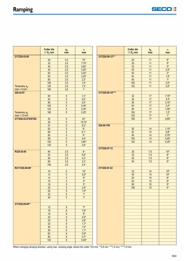
Ramping
553
Cutter dia
Dc mm
ap
max
�max
217/220.43-05
24 3,5 19�32 3,5 7,75�40 3,5 5,65�42 3,5 5,25�50 3,5 4,25�63 3,5 3,25�80 3,5 2,5�100 3,5 1,8�
Temporary apmax = 8 mm
125 3,5 1,5�160 3,5 1�
220.43-07
50 5 1,3�63 5 0,8�80 5 0,6�100 5 0,45�125 5 0,35�
Temporary apmax = 12 mm
160 5 0,25�
217/220.43-07S/07SA 32 5 23�38 5 15,75�51 5 9,3�63 5 6�68 5 6,1�80 5 5�88 5 4,5�100 5 3,65�125 5 2,8�
R220.42-05 40 3,5 8�53 3,5 5,8�60 3,5 4,3�80 3,5 3,2�100 3,5 2,4�
R217/220.69-06*
10 5 10º12 5 6,5º14 5 5º16 5 4º18 5 3º20 5 2,5º25 5 1,5º32 5 1º40 5 1º
217/220.69-09**
12 8 7º16 8 7,6º18 8 6º20 8 4,5º25 8 2,9º32 8 1,7º40 8 1,5º50 8 1,1º63 8 0,9º80 8 0,7º100 8 0,55º
Cutter dia
Dc mm
ap
max
�max
217/220.69-12***
20 11 8º25 11 5º32 11 3º40 11 2,5º50 11 2º63 11 1,5º80 11 1º100 11 0,5º125 11 0,5º
217/220.69-18****
32 17 7,15º40 17 4,5º50 17 3,15º63 17 2,4º80 17 1,55º100 17 1,3º125 17 1º160 17 0,65º
220.69-15H
50 14 1,15º63 14 0,8º80 14 0,75º100 14 0,45º125 14 0,35º
217/220.97-12
25 7,5 10º32 7,5 8º40 7,5 6º50 7,5 5º
217/220.97-22
32 10 15º40 10 10º50 10 8º63 10 6º80 10 5º100 10 4º
When changing ramping direction, using max. ramping angle, retract the cutter *0,6 mm, **0,8 mm, ***1,4 mm, ****1,9 mm.
Milling_090109_14.fm Page 553 Tuesday, January 27, 2009 2:05 PM

Helical interpolation ramping
554
Helical interpolation ramping
The milling cutter design and the clearance on the bottom side of the choseninsert determines the tool’s suitability for helical interpolation ramping.
Maximum and minimum hole diameters and maximum cutting depth perrevolution recommendations for suitable tools are in the tables below.
Use the cutting speeds and feed rates recommended fornormal operations.
Cutter
dia Ø
Dc mm
Cutter
dia Ø
Dc2 mm
C min/ap max C max/ap max
C min
Ø
ap
max mm
C max
Ø
ap
max mm
217/220.29-025
5 10 15 2,5 19 2,57 12 19 2,5 23 2,510 15 25 2,5 29 2,515 20 35 2,5 39 2,5
217/220.29-03
4* 10* 14 3 19 36 12 18 3 23 310 16 26 3 31 314 20 34 3 39 319 25 44 3 49 326 32 58 3 63 329 25 64 3 69 334 40 74 3 79 3
217/220.29-035
8 15 23 3,5 29 3,59 16 25 3,5 31 3,513 20 33 3,5 39 3,518 25 43 3,5 49 3,528 35 63 3,5 69 3,5
217.29-04
4* 12* 16 4 23 48 16 24 4 31 412 20 32 4 39 417 25 42 4 49 424 32 56 4 63 427 35 62 4 69 432 40 72 4 79 442 50 92 4 99 4
217/220.29-05
6* 16* 22 5 31 510 20 30 5 39 515 25 40 5 49 522 32 54 5 63 525 35 60 5 69 530 40 70 5 79 540 50 90 5 99 5
Cutter
dia Ø
Dc mm
Cutter
dia Ø
Dc2 mm
C min/ap max C max/ap max
C min
Ø
ap
max mm
C max
Ø
ap
max mm
217/220.29-06
4* 16* 25 6 30 68 20 28 6 8 612 24 36 6 46 613 25 38 6 48 620 32 52 6 62 623 35 58 6 68 628 40 68 6 78 632 44 76 6 86 628 50 88 6 98 640 52 92 6 102 650 62 112 6 122 651 63 114 6 124 654 66 120 6 130 663 75 138 6 148 668 80 148 6 158 680 92 172 6 182 6
100 112 212 6 222 6125 137 262 6 272 6
217/220.29-08
16 32 48 8 62 824 40 64 8 78 834 50 84 8 98 836 52 88 8 102 847 63 110 8 124 850 66 116 8 130 864 80 144 8 158 884 100 184 8 198 8
109 125 234 8 248 8144 160 304 8 318 8
217/220.29-10
5* 25* 25 10 48 1020 40 60 10 78 1030 50 80 10 98 1043 63 106 10 124 1050 70 120 10 138 1060 80 140 10 158 1063 83 146 10 164 1080 100 180 10 198 10
100 120 220 10 238 10105 125 230 10 248 10140 160 300 10 318 10
Milling_090109.book Page 554 Friday, January 9, 2009 12:56 PM
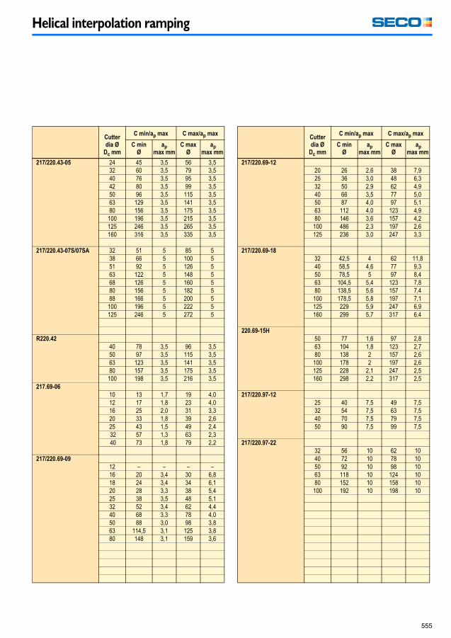
Helical interpolation ramping
555
Cutter
dia Ø
Dc mm
C min/ap max C max/ap max
C min
Ø
ap
max mm
C max
Ø
ap
max mm
217/220.43-05 24 45 3,5 56 3,532 60 3,5 79 3,540 76 3,5 95 3,542 80 3,5 99 3,550 96 3,5 115 3,563 129 3,5 141 3,580 156 3,5 175 3,5
100 196 3,5 215 3,5125 246 3,5 265 3,5160 316 3,5 335 3,5
217/220.43-07S/07SA 32 51 5 85 538 66 5 100 551 92 5 126 563 122 5 148 568 126 5 160 580 156 5 182 588 166 5 200 5
100 196 5 222 5125 246 5 272 5
R220.42
40 78 3,5 96 3,550 97 3,5 115 3,563 123 3,5 141 3,580 157 3,5 175 3,5
100 198 3,5 216 3,5217.69-06
10 13 1,7 19 4,012 17 1,8 23 4,016 25 2,0 31 3,320 33 1,8 39 2,625 43 1,5 49 2,432 57 1,3 63 2,340 73 1,8 79 2,2
217/220.69-09
12 – – – –16 20 3,4 30 6,818 24 3,4 34 6,120 28 3,3 38 5,425 38 3,5 48 5,132 52 3,4 62 4,440 68 3,3 78 4,050 88 3,0 98 3,863 114,5 3,1 125 3,880 148 3,1 159 3,6
Cutter
dia Ø
Dc mm
C min/ap max C max/ap max
C min
Ø
ap
max mm
C max
Ø
ap
max mm
217/220.69-12
20 26 2,6 38 7,925 36 3,0 48 6,332 50 2,9 62 4,940 66 3,5 77 5,050 87 4,0 97 5,163 112 4,0 123 4,980 146 3,6 157 4,2100 486 2,3 197 2,6125 236 3,0 247 3,3
217/220.69-18
32 42,5 4 62 11,840 58,5 4,6 77 9,350 78,5 5 97 8,463 104,5 5,4 123 7,880 138,5 5,6 157 7,4100 178,5 5,8 197 7,1125 229 5,9 247 6,9160 299 5,7 317 6,4
220.69-15H
50 77 1,6 97 2,863 104 1,8 123 2,780 138 2 157 2,6100 178 2 197 2,6125 228 2,1 247 2,5160 298 2,2 317 2,5
217/220.97-12
25 40 7,5 49 7,532 54 7,5 63 7,540 70 7,5 79 7,550 90 7,5 99 7,5
217/220.97-22
32 56 10 62 1040 72 10 78 1050 92 10 98 1063 118 10 124 1080 152 10 158 10100 192 10 198 10
Milling_090109_14.fm Page 555 Tuesday, January 27, 2009 2:05 PM

Plunge milling
556
Plunge milling
The insert design and the insert clamping system determines the tool’s suitability for plunging.Maximum cutting depth recommendations for suitable tools are in the tables below. Note that the definition of ap is different for plunge milling.Use the cutting speeds and feed rates recommended for normal operations.Values for milling cutters designed for plunge milling only can be found in the chapter Plunge milling cutters R217/220.79 Milling 2
Plunging
Type of cutter
ap max
mm
220.43…-05 10220.43…-07W 8217/220.43…07SA/07S 12217.69-06 3,5217/220.69…-09 4217/220.69…-12 7217/220.69…15H/15.xH 10217/220.29-03 3217/220.29-04 4217/220.29-05 5217/220.29-06 6217/220.29-08 8217/220.29-10 10217.96-08 7,5
% of ap max
Overhang ratio Dcap max can normally be used if the overhang ratio is up to 4 but should be reduced at higher ratios as shown in the graph.
Plunging - Axial feed direction
Type of cutter
ap max
mm
220.43…-05 5*220.43…-07W 7*217/220.43…07SA/07S 7*217.69-06 3,5*217/220.69…-09 4*217/220.69…-12 7*217/220.69…15H/15.xH 10*217/220.29-03 3217/220.29-04 4217/220.29-05 5217/220.29-06 6217/220.29-08 8217/220.29-10 10217.96-08 7,5
Slotting - Axial feed direction
Type of cutter
ap max
mm
220.43…-05 5*220.43…-07W 7*217/220.43…07SA/07S 7*217.69-06 3,5*217/220.69…-09 4*217/220.69…-12 7*217/220.69…15H/15.xH 10*217/220.29-03 3217/220.29-04 4217/220.29-05 5217/220.29-06 6217/220.29-08 8217/220.29-10 10217.96-08 7,5
*To create a flat bottom surface, ap max = the wiper flat width. Dimensions to be found on the cutting data pages.
Milling_090109.book Page 556 Friday, January 9, 2009 12:56 PM

Cutting data calculation
557
Cutting data calculation
Nomenclature and formulae
RPM
(rev/min)
Cutting speed
(m/min)
Feed speed
(mm/min)
(mm/min)
Feed per revolution
(mm/rev)
(mm/rev)
Metal removal rate
(cm3/min)
Cutting speed and RPM for copying
(m/min)
(RPM)
(mm)
Effective No. of teeth (zc)
The effective No. of teeth (zc) is used to calculate the feed speed (vf) and the feed per revolution (f). For most of the cutters the effective No. of teeth (zc) is equal to the No. of teeth in the cutter (zn), but for some of the cutters zc is less than zn.
ae = Width of cut mm/radial depth of cut mm
ap = Depth of cut mm/axial depth of cut mm
Dc = Cutter diameter mm
f = Feed per revolution mm/rev
fz = Feed per tooth mm/tooth
zc = Effective No. of teeth for calculation offeed speed or feed per rev (see below)
n = RPM rev/min
Q = Material removal rate cm3/min
vc = Cutting speed m/min
vf = Feed speed mm/min
zn = No of teeth
Example: Disc mill 335.19Total No. of teeth (zn) = 12 Effective No. of teeth (zc) = 6
Explanation: 6 inserts on one side of the cutter and 6 overlappinginserts on the other side are used to get the full width (ap) ,which means zc = 6.
Milling_090109_14.fm Page 557 Tuesday, January 27, 2009 2:16 PM

Cutting data calculation
558
Internal circular interpolationWhen using circular interpolation or helical interpolation ramping to increase the diameter of a hole in a workpiece, the stock removal depth is not the same as the width of cut value. The real width of cut must be calculated from the formula below.
The width of cut value is then used for calculation of feed/tooth and feed speed.
External circular interpolationWhen using external circular interpolation or helical interpolation ramping to decrease the diameter of a round workpiece the stock removal depth is not the same as the width of cut value. The real width of cut must be calculated from the formula below.
The width of cut is then used for calculation of feed/tooth and feed speed.
Increase the width of cutsuccessively to full valueFor circular interpolation operations it is recommended to successively increase the widthof cut up to full value. When using radial infeed up to full width of cut, reduce the feed/tooth and feed speed to half.
Successive increase of width ofcut – recommended method.
Radial infeed –Reduce feed/tooth.
Feed speed related to the centre of the cutterWhen calculating feed speed and feed/tooth from average chip thickness using circular interpolation or helical interpolation ramping in an operation, the feed speed and feed/tooth are always related to the centre and not to the periphery of the cutter.
Int.
Ext.
Stockremovaldepth
ae > Stock removal depth
Stock removaldepth
ae > Stock removal depth
Circle formovement of
centre of cutter
ae > Stock removal depth
Milling_090109.book Page 558 Friday, January 9, 2009 12:56 PM

Cutting data calculation
559
Slot milling compared with side milling
Slot milling Side milling
Relative engagement of the cutter
diameter (ae/Dc=%)
Multiply the feed per tooth by the following
factor
30%20%10%5%
1.251.52.03.0
Calculation of feed per tooth and cutting speed for side milling operations
When using side milling it is necessary to increase the feed per tooth to keep the chip thickness at the same value. It is also possible to increase the cutting speed and keep the same tool life. Use the tables below.
This table can be used for cutters with cutting edge angle = 90
ae/Dc
%
Feed Per Tooth, mm/tooth (fz)
Speed
Factor0,03 0,06 0,08 0,10 0,15 0,20 0,25 0,30 0,40 0,50 0,60 0,80 1,00
Average Chip Thickness, mm/tooth (hm)
Width of cut up to and including D/2
2 (0.02) 0,02 0,03 0,04 0,04 0,06 0,07 0,08 0,11 0,14 1.8
3 (0.03) 0,02 0,03 0,03 0,04 0,05 0,07 0,09 0,10 0,14 0,17 1.7
5 (0.05) 0,02 0,02 0,03 0,04 0,06 0,07 0,09 0,11 0,13 0,18 0,22 1.6
10 (0.10) 0,02 0,02 0,03 0,05 0,06 0,08 0,09 0,12 0,16 0,19 0,25 0,31 1.5
15 (0.15) 0,011 0,02 0,03 0,04 0,06 0,08 0,09 0,11 0,15 0,19 0,23 0,30 1.4
20 (0.20) 0,013 0,03 0,03 0,04 0,06 0,09 0,11 0,13 0,17 0,22 0,26 1.35
30 (0.30) 0,016 0,03 0,04 0,05 0,08 0,10 0,13 0,16 0,21 0,26 0,31 1.3
40 (0.40) 0,018 0,04 0,05 0,06 0,09 0,12 0,15 0,18 0,23 0,29 1.25
50 (0.50) 0,02 0,04 0,05 0,06 0,10 0,13 0,16 0,19 0,25 0,32 1.2
Slotting (Width of cut = D)
100 (1.00) 0,02 0,04 0,05 0,06 0,10 0,13 0,16 0,19 0,25 0,32 1.0
= Feed per tooth correction example: at 20% engagement also increase speed by 1.35
Instead of using the table above for calculating hm and fz, the following formula could be used if ae/Dc < 30%.
Milling_090109_14.fm Page 559 Tuesday, January 27, 2009 2:05 PM
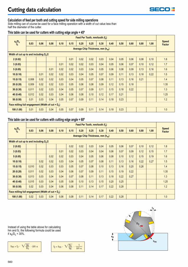
Cutting data calculation
560
Calculation of feed per tooth and cutting speed for side milling operationsSide milling can of course be used for a face milling operation with a width of cut value less than half the diameter of the cutter.
This table can be used for cutters with cutting edge angle = 45º
ae/Dc
%
Feed Per Tooth, mm/tooth (fz)
Speed
Factor0,03 0,06 0,08 0,10 0,15 0,20 0,25 0,30 0,40 0,50 0,60 0,80 1,00
Average Chip Thickness, mm (hm)
Width of cut up to and including Dc/2
2 (0.02) 0,01 0,02 0,02 0,03 0,04 0,05 0,06 0,08 0,10 1.8
3 (0.03) 0,01 0,02 0,02 0,03 0,04 0,05 0,06 0,07 0,10 0,12 1.7
5 (0.05) 0,01 0,02 0,02 0,03 0,04 0,05 0,06 0,08 0,09 0,13 0,16 1.6
10 (0.10) 0,01 0,02 0,02 0,03 0,04 0,05 0,07 0,09 0,11 0,13 0,18 0,22 1.5
15 (0.15) 0,008 0,02 0,02 0,03 0,04 0,05 0,07 0,08 0,11 0,13 0,16 0,21 1.4
20 (0.20) 0,009 0,02 0,02 0,03 0,05 0,06 0,08 0,09 0,12 0,15 0,18 1.35
30 (0.30) 0,011 0,02 0,03 0,04 0,05 0,07 0,09 0,11 0,15 0,18 0,22 1.3
40 (0.40) 0,012 0,02 0,03 0,04 0,06 0,08 0,10 0,12 0,17 0,21 1.25
50 (0.50) 0,01 0,03 0,04 0,05 0,07 0,09 0,11 0,14 0,18 0,23 1.2
Face milling full engagement (Width of cut = Dc)
100 (1.00) 0,01 0,03 0,04 0,05 0,07 0,09 0,11 0,14 0,18 0,23 1.0
This table can be used for cutters with cutting edge angle = 60º
ae/Dc
%
Feed Per Tooth, mm/tooth (fz)
Speed
Factor0,03 0,06 0,08 0,10 0,15 0,20 0,25 0,30 0,40 0,50 0,60 0,80 1,00
Average Chip Thickness, mm (hm)
Width of cut up to and including Dc/2
2 (0.02) 0,02 0,02 0,03 0,04 0,05 0,06 0,07 0,10 0,12 1.8
3 (0.03) 0,01 0,02 0,03 0,04 0,04 0,06 0,07 0,09 0,12 0,15 1.7
5 (0.05) 0,02 0,02 0,03 0,04 0,05 0,06 0,08 0,10 0,12 0,15 0,19 1.6
10 (0.10) 0,02 0,02 0,03 0,04 0,05 0,07 0,08 0,11 0,13 0,16 0,22 0,27 1.5
15 (0.15) 0,010 0,02 0,03 0,03 0,05 0,07 0,08 0,10 0,13 0,16 0,20 0,26 1.4
20 (0.20) 0,011 0,02 0,03 0,04 0,06 0,07 0,09 0,11 0,15 0,19 0,22 1.35
30 (0.30) 0,013 0,03 0,04 0,04 0,07 0,08 0,11 0,13 0,18 0,22 0,27 1.3
40 (0.40) 0,015 0,03 0,04 0,05 0,08 0,10 0,13 0,15 0,20 0,25 1.25
50 (0.50) 0,02 0,03 0,04 0,06 0,08 0,11 0,14 0,17 0,22 0,28 1.2
Face milling full engagement (Width of cut = Dc)
100 (1.00) 0,02 0,03 0,04 0,06 0,08 0,11 0,14 0,17 0,22 0,28 1.0
Instead of using the table above for calculating hm and fz, the following formula could be used if ae/Dc < 30%.
Milling_090109.book Page 560 Friday, January 9, 2009 12:56 PM
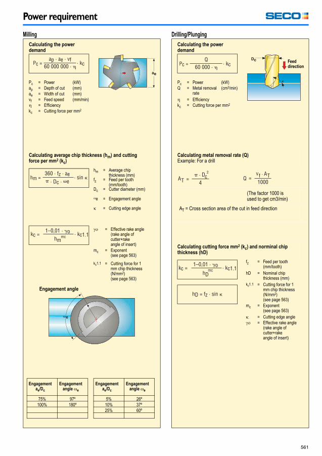
Power requirement
561
Power requirement
Milling
Calculating the power demand
Calculating average chip thickness (hm) and cuttingforce per mm2 (kc)
Engagement angle
Drilling/Plunging
Calculating the power demand
Calculating metal removal rate (Q)Example: For a drill
(The factor 1000 isused to get cm3/min)
AT = Cross section area of the cut in feed direction
Calculating cutting force mm2 (kc) and norminal chipthickness (hD)
Pc = Power (kW)ap = Depth of cut (mm)ae = Width of cut (mm)vf = Feed speed (mm/min)� = Efficiencykc = Cutting force per mm2
hm = Average chipthickness (mm)
fz = Feed per tooth(mm/tooth)
Dc = Cutter diameter (mm)
�e = Engagement angle
� = Cutting edge angle
�� = Effective rake angle(rake angle ofcutter+rakeangle of insert)
mc = Exponent(see page 563)
kc1.1 = Cutting force for 1mm chip thickness(N/mm2)(see page 563)
Engagementae/Dc
Engagementangle �e
5% 26º10% 37º25% 60º
Engagementae/Dc
Engagementangle �e
75% 97º100% 180º
Pc = Power (kW)Q = Metal removal
rate(cm3/min)
� = Efficiencykc = Cutting force per mm2
fz = Feed per tooth(mm/tooth)
hD = Nominal chipthickness (mm)
kc1.1 = Cutting force for 1mm chip thickness(N/mm2) (see page 563)
mc = Exponent(see page 563)
� = Cutting edge angle�� = Effective rake angle
(rake angle ofcutter+rakeangle of insert)
Feeddirection
Milling_090109_14.fm Page 561 Tuesday, January 27, 2009 2:05 PM

Troubleshooting
562
Troubleshooting
Vibrations
• Improve the stability of cutter and workpiece.• Change cutter positioning.• Minimize tool overhang.• Reduce the cutting speed.• Increase the feed rate.• Reduce the depth of cut.
Poor surface finish
• Improve the stability of cutter and workpiece.• Minimize tool overhang.• Reduce the feed rate.• Incease the cutting speed• Use a coolant.• Use wiper inserts.
Tool life problems
Rapid flank wear • Reduce the cutting speed.• Increase the feed rate.• Climb milling.
Rapid notch wear • Reduce the cutting speed.• Increase the feed rate.• Increase the depth of cut.• Climb milling.• Change cutter positioning.
Chipping • Increase the cutting speed.• reduce the feed rate.• Conventional milling.• Improve chip evacuation.• Change cutter positioning.• Minimize tool overhang.• Improve stability.
Comb cracks • Reduce the cutting speed.• Reduce the feed rate• No coolant.• Change cutter positioning.
Built up edge • Increase the cutting speed.• Increase the feed rate• No coolant.• Climb milling.• Change cutter positioning.
Milling_090109.book Page 562 Friday, January 9, 2009 12:56 PM

Workpiece materials – Seco material groups
563
Workpiece materials – Seco material groups
Steel
Rm (N/mm2)
kc1.1
(N/mm2) mc
1 Very soft low carbon steels.Purely ferritic steels.
<450 1350 0,21
2 Free cutting steels. 400 <700 1500 0,22
3 Structural steels. Ordinary carbon steels withlow to medium carbon content (<0,5%C).
450 <550 1500 0,25
4 Carbon steels with high carbon content (>0,5%C).Medium hard steels for toughening. Ordinary low alloy steels.Ferritic and martensitic stainless steels.
550 <700 1700 0,24
5 Normal tool steels.Harder steels for toughening.Martensitic stainless steels.
700 <900 1900 0,24
6 Difficult tool steels.High-alloy steels with high hardness.Martensitic stainless steels.
900 <1200 2000 0,24
7 Difficult high-strength steels with 42-56 HRc hardness.Hardened steels from material group 3-6.Martensitic stainless steels.
>1200 2900 0,22
Stainless steel
8 Easy austenitic stainless steels.Free cutting stainless steels. Calcium treated stainless steels.
1750 0,22
9 Moderately difficult stainless steels.Austenitic and duplex stainless steels.
1900 0,20
10 Difficult stainless steels.Austenitic and duplex stainless steels.
2050 0,20
11 Very difficult stainless steels.Austenitic and duplex stainless steels.
2150 0,20
Cast iron
12 Medium hard cast iron.Grey iron.
1150 0,22
13 Low alloy cast iron.Malleable cast iron. Nodular cast iron.
1225 0,25
14 Moderately difficult alloy cast iron.Moderately difficult malleable cast iron. Nodular cast iron.
1350 0,28
15 Difficult high alloy cast iron.Difficult malleable cast iron. Nodular cast iron.
1470 0,30
Other materials
16 Free cutting non-ferrous materials.Aluminium with <16% Si.Brass, Zinc, Magnesium.
700 0,25
17 Non-ferrous materials.Aluminium with >16% Si.Bronze, Cupro-nickel.
700 0,27
20 Nickel-, Cobalt- and Iron-based heat resistant alloys with hardness <30 HRc.Incoloy 800, Inconel 601, 617, 625. Monel 400.
2600 0,24
21 Nickel-, Cobalt- and Iron-based heat resistant alloys with hardness >30 HRc.Incoloy 925, Inconel 718, 750-X, Monel K-500.
3300 0,24
22 Titanium based alloys,Ti6Al-4V.
1450 0,23
kc1.1-values with 0 degree effective cutting rake angle. For other rake angles, reduce the kc1.1-value by 1% for every degree increase in the cutting rakeangle and vice versa, mc is the exponent used for calculating power demand. Bear in mind that the Rm-value is only an aid in the selection of thematerial group when the material has been worked by rolling, drawing, heat treatment or other methods that increase the strength of the material.
Milling_090109.book Page 563 Friday, January 9, 2009 12:56 PM
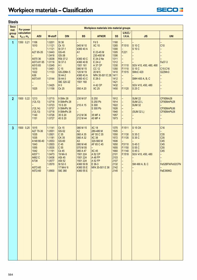
Workpiece materials – Classification
564
Workpiece materials – Classification
SteelsSeco
mat.
group
No.
For power
calculation
kc1.1 mc
Workpiece materials into material groups
AISI W-stoff DIN BS AFNOR SS
U.N.E./
I.H.A. JIS UNI
1 1350 0,21 11061010–A27 65-35–A570 36A573-81 65A515 6510151022A36A573-81––1025
1.02011.11211.11211.04431.04161.00381.01161.03451.04011.1133–1.0144–1.04251.1158
St 36Ck 10St 37-1GS-45GS-38RSt 37-2St 37-3H IC 15GS-20Mn 5St 44-2St 44-3StE 320-3ZH IICk 25
–045 M 104360 40 AA1–4360 40 C4360 40 B1501 161080 M 15120 M 194360 43 A4360 43 C1501 160–050 A 20
Fd 5XC 10–E 23-45 M230-400 ME 24-2 NeE 24-UA 37 CPCC 1220 M 5NFA 35-501 E 28E 28-3–A 42 CPXC 25
116012651300130513061311131213301350141014111412142114321450
–F.1510–F.221–––F.1110F.1110F.1515––––F.1120
–S 10 CS 10 C––––SGV 410, 450, 480, 490S 15 CSMnC 420–SMH 400 A, B, C–SGV 410, 450, 480S 25 C
–C10––––Fe37-3–C15:C16G22Mn3–––––
2 1500 0,22 1213(12L13)–(12L14)(12L13)11401151
1.07151.07181.07231.07371.07181.07261.0727
9 SMn 289 SMnPb 2815 S 209 SMnPb 369 SMnPb 2835 S 2045 S 20
230 M 07–210 A 15––212 M 36212 M 44
S 250S 250 PbS 300S 300 Pb–35 MF 445 MF 4
1912191419221926194019571973
–––––––
SUM 22SUM 22 LSUM 32–(SUM 32 L)––
CF9SMn28CF9SMnPb28–CF9SMnPb36CF9SMnPb28––
3 1500 0,25 1015A27 70-3610351035A148 80-40104310551042A537 1A662 CA738–A572-60A572-60
1.11411.05511.05011.11811.05531.05031.05351.11911.04731.04361.05771.0570–1.8900
Ck 15GS-52C 35CK 35GS-60C 45C 55Ck 4519 Mn 6ASt 45ASt 52St 52-317 MnV 6StE 380
080 M 15A2060 A 35080 A 32A3080 M 46070 M 55080 A 471501 2241501 2241501 2244360 50 B4360 55 E4360 55 E
XC 18280-480 MAF 55 C 35XC 38320-560 MAF 65 C 45–XC 45A 52 CPA 48 FPA 52 FPE 36-3NFA 35-501 E 36–
13701505155015721606165016551660210121032107213221422145
F.1511–F.1130F.1135–F.5110F.1150F.1140F.1518–––––
S 15 CK–S 35 CS 35 C–S 45 CS 55 CS 45 CSGV 410, 450, 480––SM 490 A, B, C––
C16–C35C35C45C45C55C45–––Fe52BFN/Fe52CFN–FeE390KG
Milling_090109.book Page 564 Friday, January 9, 2009 12:56 PM

Workpiece materials – Classification
565
SteelsSeco
mat.
group
No.
For power
calculation
kc1.1 mc
Workpiece materials into material groups
AISI W-stoff DIN BS AFNOR SS
U.N.E./
I.H.A. JIS UNI
4 1700 0,24 104510421064107010801095925413355120A387 12-2A182 F-22413061504135–41424140514051555210086205115A204AA355A403(410S)410P4405430434416430F409430Ti
1.17301.11911.12211.12311.12481.12741.09041.11671.08411.73371.73801.72181.81591.23301.85151.23321.72251.70451.71761.35051.65231.71311.54151.85091.40001.4001(1.4006)1.23411.47241.40161.41131.40051.41041.45121.4510
C 45WCk 45Ck 60Ck 67Ck 75Ck 10155 Si 736 Mn 5St 52-316 CrMo 4 410 CrMo 9 1025 CrMo 450 CrV 435 CrMo 431 CrMo 1247 CrMo 442 CrMo 442 Cr 4155 Cr 31100 Cr 621 NiCrMo 216 MnCr 515 Mo 342 CrAlMo 7X6 Cr 13X7 Cr 14G-X 10 Cr 13X6 CrMo 4X6 CrAl 13X6 Cr 17X6 CrMo 17X12 CrS 13X12 CrMoS 17X5 CrTi 12X6 CrTi 17
En 43 B080 M 46060 A 62070 A 72060 A 78060 A 96250 A 53150 M 36150 M 191501 6201501 622CDS 110735 A 50708 A 37722 M 24708 M 40708 M 40530 A 40527 A 60534 A 99805 H 20527 M 171501 240905 M 39403 S 17(403 S17)410 S21–405 S 17430 S 17434 S 17416 S 21420 S 37409 S 19–
––XC 65XC 68XC 75XC 10055 S 740 M 520 MC 515 CD 4.512 CD 9.1025 CD 450 CV 434 CD 430 CD 1242 CD 442 CD 442 C 4 TS55 C 3100 C 620 NCD 216 MC 515 D 340 CAD 6.12Z 8 C 13Z 8 C 13Z 10 C 13 M–Z 8 CA 12Z 8 C 17–Z 11 CF 13Z 13 CF 17Z 6 CT 12Z 4 CT 17
167216721678177017741870209021202172221622182225223022342240224422442245225322582506251129122940230123012302––2320232523802383––
F.114–F.1150F.5103F.5107F.5117F.144F.411F.431–F.155F.1251F.143F.1250F.1712–F.1252F.1207–F.5230F.1522F.1516–F.1740–F.3110F.3401––F.3113–F.3411F.3117––
–S 45 CS 58 C––SUP 4–SMn 438(H)–––SCM 420SUP 10SCM 432–SCM 440SCM 440SCr 440SUP 9(A)SUJ 2, SUJ 4SNCM 220(H)––SUS 403SUS 410 SSUS 410–SUS 405SUS 430SUS 434–SUS 430 FSUH 409––
–C45C60C70––5SSi8–Fe5212CrMo910/G14CrMo91025CrMo450CrV4–30CrMo12–42CrMo4–55Cr31100Cr620NiCrMo216MnCr516Mo341CrAlMo7X6Cr13X6Cr13X12Cr13–X10CrAl12X8Cr17X8CrMo17X12CrS13X10CrS17X6CrTi12X6CrTi17
5 1900 0,24 W1420–L3P20 + 1O16 F7–4340–S1420(420)(420)–431440B
1.15451.40211.21081.22101.23121.25101.2767–1.65821.67461.25421.40211.40281.40311.49231.40571.4112
C105W1X42 Cr 1390 CrSi 5115 CrV 340 CrMnMoS 8 6100 MnCrW 4X45 NiCrMo 6 731 NiCrMo 13 434 CrNiMo 632 NiCrMo 14 545 WCrV 7X20 Cr 13X30 Cr 13X40 Cr 13X22 CrMoV 12 1X20 CrNi 17 2X90 CrMoV 18
BW1A420 S 37–BL 3–BO1En 30 B830 M 31817 M 40830 M 31BS1420 S 37420 S 45––431 S 29–
Y 105Z 20 C 13–Y 100 C 6–8 Mo 8––35 NCD 635 NCD 1455 WC 20Z 20 C 13Z 30 C 13Z 40 C 14–Z 15 CN 16-02–
1880(2314)2092(2140)–2140–25342541–27102303(2304)(2304)–2321–
F.5118F.3402F.5230F.520LX210CrW12F.5220–F.1270F.1280F.1260F.5241F.5261F.5263F.3404–F.313–
–SUS 420 J1––––––SNCM 447––SUS 420 J 1(SUS 420 J 1)(SUS 420 J 1)–SUS 431SUS 440 B
C38KUX20Cr13C100KU––95MnWCr5KU––35NiCrMo6KB–45WCrV8KUX20Cr13X30Cr13/XG40Cr13X40Cr14–X16CrNi16–
Milling_090109.book Page 565 Friday, January 9, 2009 12:56 PM

Workpiece materials – Classification
566
SteelsSeco
mat.
group
No.
For power
calculation
kc1.1 mc
Workpiece materials into material groups
AISI W-stoff DIN BS AFNOR SS
U.N.E./
I.H.A. JIS UNI
6 2000 0,24 P3P20H13A2D2D4 (D6)–L6–M 2M 35M 7446422429440C
1.20801.23111.23441.23631.23791.24361.27131.27211.73211.33431.32431.33481.47491.4935–1.4125
X210 Cr 1240 CrMnMo 7X40CrMoV 5 1X100 CrMoV 5 1X155 CrMoV 12 1X210 CrW 1255NiCrMoV 650 NiCr 1320 MoCr 4S6/5/2S6/5/2/5S2/9/2X18 CrN 28X20 CrMoWV 12 1X10 CrNi 15X105 CrMo 17
BD3–BH11BA2BD2BD6–––BM2––––––
Z 200 C 12–Z 38 CDV 5Z 100 CDV 5Z 160 CDV 12Z 200 CD 12–55 NCV 6–Z 85 WDCV6-5-2-5––––Z 100 CD 17
2710–2242226023102312–25502625272227232782––––
F.5212F.5263F.5318F.5227F.5211F.5213F.520.SF.528F.1523F.5603F.5613–––––
SKD 1–SKD 61SKD 12–SKD 2–SKT 4–SKH 9SKH 55–SUH 446––SUS 440 C
––X40CrMoV511KUX100CrMoV51KUX155CrVMo121KUX215CrW121K––30CrMo4HS6-5-2-2HS6-5-5HS2-9-2X16Cr26–––
7 2900 0,22 A128 75 1.3401 G-X120 Mn 12 BW10 Z 120 M 12 2183 – SCMnH 1 –
Milling_090109.book Page 566 Friday, January 9, 2009 12:56 PM
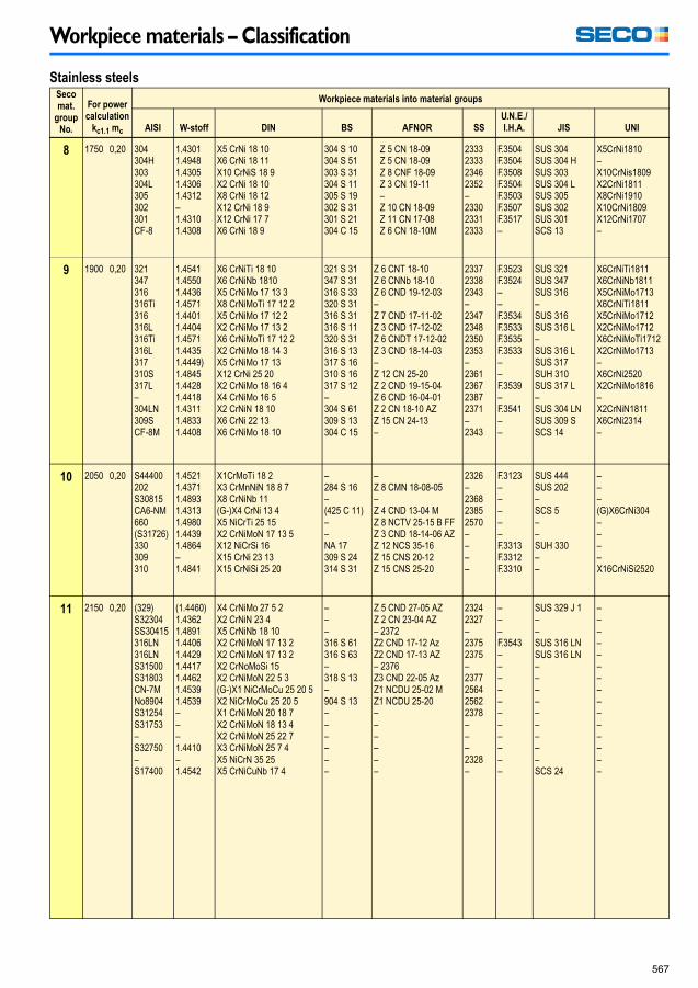
Workpiece materials – Classification
567
Stainless steelsSeco
mat.
group
No.
For power
calculation
kc1.1 mc
Workpiece materials into material groups
AISI W-stoff DIN BS AFNOR SS
U.N.E./
I.H.A. JIS UNI
8 1750 0,20 304304H303304L305302301CF-8
1.43011.49481.43051.43061.4312–1.43101.4308
X5 CrNi 18 10X6 CrNi 18 11X10 CrNiS 18 9X2 CrNi 18 10X8 CrNi 18 12X12 CrNi 18 9X12 CrNi 17 7X6 CrNi 18 9
304 S 10304 S 51303 S 31304 S 11305 S 19302 S 31301 S 21304 C 15
Z 5 CN 18-09Z 5 CN 18-09Z 8 CNF 18-09Z 3 CN 19-11–Z 10 CN 18-09Z 11 CN 17-08Z 6 CN 18-10M
2333233323462352–233023312333
F.3504F.3504F.3508F.3504F.3503F.3507F.3517–
SUS 304SUS 304 HSUS 303SUS 304 LSUS 305SUS 302SUS 301SCS 13
X5CrNi1810–X10CrNis1809X2CrNi1811X8CrNi1910X10CrNi1809X12CrNi1707–
9 1900 0,20 321347316316Ti316316L316Ti316L317310S317L–304LN309SCF-8M
1.45411.45501.44361.45711.44011.44041.45711.44351.4449)1.48451.44281.44181.43111.48331.4408
X6 CrNiTi 18 10X6 CrNiNb 1810X5 CrNiMo 17 13 3X8 CrNiMoTi 17 12 2X5 CrNiMo 17 12 2X2 CrNiMo 17 13 2X6 CrNiMoTi 17 12 2X2 CrNiMo 18 14 3X5 CrNiMo 17 13X12 CrNi 25 20X2 CrNiMo 18 16 4X4 CrNiMo 16 5X2 CrNiN 18 10X6 CrNi 22 13X6 CrNiMo 18 10
321 S 31347 S 31316 S 33320 S 31316 S 31316 S 11320 S 31316 S 13317 S 16310 S 16317 S 12–304 S 61309 S 13304 C 15
Z 6 CNT 18-10Z 6 CNNb 18-10Z 6 CND 19-12-03–Z 7 CND 17-11-02Z 3 CND 17-12-02Z 6 CNDT 17-12-02Z 3 CND 18-14-03–Z 12 CN 25-20Z 2 CND 19-15-04Z 6 CND 16-04-01Z 2 CN 18-10 AZZ 15 CN 24-13–
233723382343–2347234823502353–2361236723872371–2343
F.3523F.3524––F.3534F.3533F.3535F.3533––F.3539–F.3541––
SUS 321SUS 347SUS 316–SUS 316SUS 316 L–SUS 316 LSUS 317SUH 310SUS 317 L–SUS 304 LNSUS 309 SSCS 14
X6CrNiTi1811X6CrNiNb1811X5CrNiMo1713X6CrNiTi1811X5CrNiMo1712X2CrNiMo1712X6CrNiMoTi1712X2CrNiMo1713–X6CrNi2520X2CrNiMo1816–X2CrNiN1811X6CrNi2314–
10 2050 0,20 S44400202S30815CA6-NM660(S31726)330309310
1.45211.43711.48931.43131.49801.44391.4864–1.4841
X1CrMoTi 18 2X3 CrMnNiN 18 8 7X8 CrNiNb 11(G-)X4 CrNi 13 4X5 NiCrTi 25 15X2 CrNiMoN 17 13 5X12 NiCrSi 16X15 CrNi 23 13X15 CrNiSi 25 20
–284 S 16–(425 C 11)––NA 17309 S 24314 S 31
–Z 8 CMN 18-08-05–Z 4 CND 13-04 MZ 8 NCTV 25-15 B FFZ 3 CND 18-14-06 AZZ 12 NCS 35-16Z 15 CNS 20-12Z 15 CNS 25-20
2326–236823852570––––
F.3123–––––F.3313F.3312F.3310
SUS 444SUS 202–SCS 5––SUH 330––
–––(G)X6CrNi304––––X16CrNiSi2520
11 2150 0,20 (329)S32304SS30415316LN316LNS31500S31803CN-7MNo8904S31254S31753–S32750–S17400
(1.4460)1.43621.48911.44061.44291.44171.44621.45391.4539–––1.4410–1.4542
X4 CrNiMo 27 5 2X2 CrNiN 23 4X5 CrNiNb 18 10X2 CrNiMoN 17 13 2X2 CrNiMoN 17 13 2X2 CrNoMoSi 15X2 CrNiMoN 22 5 3(G-)X1 NiCrMoCu 25 20 5X2 NiCrMoCu 25 20 5X1 CrNiMoN 20 18 7X2 CrNiMoN 18 13 4X2 CrNiMoN 25 22 7X3 CrNiMoN 25 7 4X5 NiCrN 35 25X5 CrNiCuNb 17 4
–––316 S 61316 S 63–318 S 13–904 S 13––––––
Z 5 CND 27-05 AZZ 2 CN 23-04 AZ– 2372Z2 CND 17-12 AzZ2 CND 17-13 AZ– 2376Z3 CND 22-05 AzZ1 NCDU 25-02 MZ1 NCDU 25-20––––––
23242327–23752375–2377256425622378–––2328–
–––F.3543–––––––––––
SUS 329 J 1––SUS 316 LNSUS 316 LN–––––––––SCS 24
–––––––––––––––
Milling_090109.book Page 567 Friday, January 9, 2009 12:56 PM

Workpiece materials – Classification
568
Cast ironSeco
mat.
group
No.
For power
calculation
kc1.1 mc
Workpiece materials into material groups
AISI W-stoff DIN BS AFNOR SS
U.N.E./
I.H.A. JIS UNI
12 1150 0,22 A48-25B60/40/1860/40/18–A220-40010A220-50005
0.60150.70400.70430.70330.81450.8155
GG-15GGG-40GGG-40.3GGG-35.3GTS-45-06GTS-55-04
Grade 150400/17370/17350/22L40P440/7P510/4
Ft 15 DFGS 370/17FGS 370/17FGS 370/17Mn 450-6Mn 550-4
0115-000717-020717-150717-150852-000854-00
FG 15FGE 38-17––––
FC 150FCD 400––FCMP 440/490FCMP 540
G15GS 370-17––GMN 45GMN 55
13 1225 0,25 A48-30BA48-40BA436 Type 265/45/1280/55/06–A220-50005A220-70003
0.60200.60250.66600.70500.70600.76520.81550.8165
GG-20GG-25GGL-NiCr 20 2GGG-50GGG-60GGG-NiMn 13 7GTS-55-04GTS-65-02
Grade 200Grade 260L-NiCuCr202500/7600/3S-NiMn 137P510/4P570/3
Ft 20 DFt 25 DL-NC 202FGS 500/7FGS 600/3S-Mn 137Mn 550-4Mn 650-3
0120-000125-000523-000727-020727-030772-000854-000856-00
FG 20FG 25–FGE 50-7FGE 60-2–––
FC 200FC 250–FCD 500FCD 600–FCMP 540FCMP 590
G 20G 25–GS 500-7GS 600-2–GMN 55GMN 65
14 1350 0,28 A48-45B100/70/03A43D2A220-70003A220-80002A220-90001
0.60300.70700.76600.81650.81700.8170
GG-30GGG-70GGG-NiCr 20 2GTS-65-02GTS-70-02GTS-70-02
Grade 300700/2Grade S6P570/3P690/2–
Ft 30 DFGS 700/2S-NC 202Mn 650-3Mn 700-2–
0130-000737-010776-000856-000862-000864-00
FG 30FGE 70-2––––
FC 300FCD 700–FCMP 590FCMP 690–
G 30GS 700-2–GMN 65GMN 70GMN 70
15 1470 0,30 A48-50BA48-60BA220-90001
0.60350.60400.8170
GG-35GG-40GTS-70-02
Grade 350Grade 400–
Ft 35 DFt 40 DMn 700-2
0135-000140-000864-00
FG 35––
FC 35FC 40FCMP 690
G 35–GMN 70
Milling_090109.book Page 568 Friday, January 9, 2009 12:56 PM

Declaration of Conformity
569
Declaration of Conformity
Cemented carbide inserts and insert carriers
Cemented carbide inserts and Cemented carbide insert carriers from Seco Tools are not included in the product range intended for the following requirements. Nevertheless Seco Tools can make the following declaration.These product meets all requirements in RoHS (Restriction of the use of certain Hazardous Substances in electrical and electronic equipment), WEEE (Waste Electrical & Electronic Equipment) and ELV (End of Life Vehicles) requirements.Products do not contain mercury, lead, hexavalent chromium, cadmium, CFC, HCFC, flame retardants or solvents in concentrations that exceed specifications in the regulations.Regrinding:Wet or dry grinding can produce potentially hazardous dusts or mists that can irritate skin, eyes, nose, throat and result in lung damage or disease. To avoid injury use proper safety precautions and protective equipment.Disposal:Seco Tools will buy back used inserts and solid carbide tools for recycling. Inserts and solid carbide tools should be separated from other metal waste (steel, aluminium, copper etc).All packing material is fully recyclable.
CBN and PCD inserts
Inserts from Seco Tools are not included in the product range intended for the following requirements. Nevertheless Seco Tools can make the following declaration.This product meets all requirements in RoHS (Restriction of the use of certain Hazardous Substances in electrical and electronic equipment), WEEE (Waste Electrical & Electronic Equipment) and ELV (End of Life Vehicles) requirements.Products do not contain mercury, lead, hexavalent chromium, cadmium, CFC, HCFC, flame retardants or solvents in concentrations that exceed specifications in the regulations.Regrinding:Wet or dry grinding can produce potentially hazardous dusts or mists that can irritate skin, eyes, nose, throat and result in lung damage or disease. To avoid injury use proper safety precautions and protective equipment.Disposal:Seco Tools will buy back used CBN- or PCD-tipped inserts for recycling. Inserts should be separated from other metal waste (steel, aluminium, copper etc). Solid CBN-insert may be discarded as landfill waste.All packing material is fully recyclable.
Milling_090109.book Page 569 Friday, January 9, 2009 12:56 PM

Declaration of Conformity
570
Cermet inserts
Inserts from Seco Tools are not included in the product range intended for the following requirements. Nevertheless Seco Tools can make the following declaration.This product meets all requirements in RoHS (Restriction of the use of certain Hazardous Substances in electrical and electronic equipment), WEEE (Waste Electrical & Electronic Equipment) and ELV (End of Life Vehicles) requirements.Inserts do contain Nickel and will leach Nickel when in contact with the skin. Amount of leaching is higher than specified in norm SS-EN 1811 Reference test method for release of nickel from products intended to come into direct and prolonged contact with the skin. These norms are intended for products that are in direct and prolonged contact with the skin and are therefore not directly applicable for cermet inserts. Persons with known allergic reactions to nickel are advised to wear protective gloves when handling cermet inserts.Regrinding:Wet or dry grinding can produce potentially hazardous dusts or mists that can irritate skin, eyes, nose, throat and result in lung damage or disease. To avoid injury use proper safety precautions and protective equipment.Disposal:Used inserts may be recycled. Inserts should be separated from other metal waste (steel, aluminium, copper, etc) including cement-ed carbide inserts.All packing material is fully recyclable.
Black oxide insert carriers
Insert carriers from Seco Tools are not included in the product range intended for the following requirements. Nevertheless Seco Tools can make the following declaration.This product meets all requirements in RoHS (Restriction of the use of certain Hazardous Substances in electrical and electronic equipment), WEEE (Waste Electrical & Electronic Equipment) and ELV (End of Life Vehicles) requirements.Products do not contain mercury, lead, hexavalent chromium, cadmium, CFC, HCFC, flame retardants or solvents in concentrations that exceed specifications in the regulations.Disposal:Used insert carriers may be sent for recycling together with ordinary steel waste (swarf and discarded steel scrap) for recycling.All packing material is fully recyclable.
Milling_090109.book Page 570 Friday, January 9, 2009 12:56 PM

Declaration of Conformity
571
Nickel coated insert carriers
Insert carriers from Seco Tools are not included in the product range intended for the following requirements. Nevertheless Seco Tools can make the following declaration.This product meets all requirements in RoHS (Restriction of the use of certain Hazardous Substances in electrical and electronic equipment), WEEE (Waste Electrical & Electronic Equipment) and ELV (End of Life Vehicles) requirements.Products do not contain mercury, lead, hexavalent chromium, cadmium, CFC, HCFC, flame retardants or solvents in concentrations that exceed specifications in the regulations.Insert carriers do contain Nickel and will leach Nickel when in contact with the skin. Amount of leaching is higher then norm SS-EN 1811 Reference test method for release of nickel from products intended to come into direct and prolonged contact with the skin. These norms are intended for products that are in direct and prolonged contact with the skin and are therefore not directly applicable for insert carriers. Persons with known allergic reactions to nickel are advised to wear protective gloves when handling Nickel coated insert carriers.As Ni leaching is regarded as the highest priority within our environmental portfolio, SECO TOOL will continue to focus on solving this issue and we expect to implement a new process during 2009 that will meet the demand according to SS-EN 1811.Disposal:Used tools maybe sent for recycling together with ordinary steel waste (swarf and discarded steel scrap) for recycling.All packing material is fully recyclable.
Milling_090109.book Page 571 Friday, January 9, 2009 12:56 PM

Declaration of Conformity
572
Intentionally added alloying elements
GradeCemented carbide Coating
W Ti Ta Nb Co Cr Ni Mo C N Ti Al C N O
CM [ [ [ [ [ [ [ [ [CMP [ [ [ [ [ [ [ [ [ [ [ [CP200 [ [ [ [ [ [ [CP250 [ [ [ [ [ [ [CP300 [ [ [ [ [ [ [ [ [CP500 [ [ [ [ [ [ [CP600 [ [ [ [ [ [ [C15M [ [ [ [ [ [ [ [ [DP2000 [ [ [ [ [ [ [ [ [ [F15M [ [ [ [ [ [ [F25M [ [ [ [ [ [ [ [ [F30M [ [ [ [ [ [ [F40M [ [ [ [ [ [ [HX [ [ [ [H15 [ [ [ [H25 [ [ [ [KX [ [ [ [MH1000 [ [ [ [ [ [ [MK1500 [ [ [ [ [ [ [ [ [MK2000 [ [ [ [ [ [ [MK3000 [ [ [ [ [ [ [ [ [ [MP1500 [ [ [ [ [ [ [ [ [ [MP2500 [ [ [ [ [ [ [ [ [ [MP3000 [ [ [ [ [ [ [MS2500 [ [ [ [ [ [ [ [ [ [TK1000 [ [ [ [ [ [ [ [ [ [ [TK2000 [ [ [ [ [ [ [ [ [ [ [ [TM2000 [ [ [ [ [ [ [ [ [ [ [ [TM4000 [ [ [ [ [ [ [ [ [ [ [ [TP1000 [ [ [ [ [ [ [ [ [ [ [ [TP1500 [ [ [ [ [ [ [ [ [ [ [ [TP200 [ [ [ [ [ [ [ [ [ [ [ [TP2000 [ [ [ [ [ [ [ [ [ [ [ [TP2500 [ [ [ [ [ [ [ [ [ [ [ [TP3000 [ [ [ [ [ [ [ [ [ [ [ [TP40 [ [ [ [ [ [ [ [TS2000 [ [ [ [ [ [ [TS2500 [ [ [ [ [ [ [T1000D [ [ [ [ [ [ [ [ [ [ [ [T150M [ [ [ [ [ [ [ [ [T200M [ [ [ [ [ [ [ [ [ [T2000D [ [ [ [ [ [ [ [ [ [T25M [ [ [ [ [ [ [ [T250M [ [ [ [ [ [ [ [ [ [T250D [ [ [ [ [ [ [T3000D [ [ [ [ [ [ [ [ [ [T350M [ [ [ [ [ [ [ [ [ [T400D [ [ [ [ [ [ [T60M [ [ [ [ [ [ [ [ [883 [ [ [ [890 [ [ [ [
Milling_090109.book Page 572 Friday, January 9, 2009 12:56 PM
Related Documents