Innovative TEM Exploration in Surface Exploration and Underground Mine Settings – a Development and Operational P erspective in Australia Williams, P. K. [1] , Kepic, A. [2] , Gibson, L. [3] , Sheppard, S. [3] _________________________ 1. Independence Group NL, South Perth, Australia 2. Curtin University of Technology, Perth, Australia 3. Lightning Nickel Pty Ltd., Kambalda, Australia ABSTRACT Over the last 30 years there has been a steady drive to develop EM prospecting systems capable of locating the relatively small but very high conductance ores typically associated with the Kambalda-style of nickel sulphide mineralisation, Western Australia. In the last fifteen years, a dual strategy of ground and underground approaches has proved the most effective to address the complex geological and geophysical problems. Underground approaches evolved initially using coil-based sensor technology capable of measuring B-field outcomes. In recent years, SQUIDs sensors and array systems have shown that surface prospecting is still possible even in extremely inhospitable terrains. With the surge in nickel prices in the last few years, even more geophysical innovation is expected in the coming decade. INTRODUCTION The paper first briefly reviews the key developments in the development and application of TEM in Australia over the past 3 decades, and then describes the new developments in the last decade. The origin of TEM surveying in Australia can be traced back to the Russian designed and built MPP-01 instrument ation, which was first imported into Australia by WMC in the late 1960’s and early 1970’s. The instrumentation although bulky, complex and limited in bandwidth and power, was successfully trialled over the Edwin Nickel Sulphide deposit showing not only de tection of the deposit but a clear indication of the geometry of the mineralization. Hence the concept of TEM surveying had immediate appeal, and replaced Induced Polarization (IP) surveying as the survey of choice for massive Nickel Sulphide exploration. Despite pitfalls, the period from 1967 to 1977 saw the ascendance of TEM surveying in base metal exploration in Australia as it was far more productive and less expensive than IP. The Commonwealth Science and Industrial Research Organisation (CSIRO, Australia) took the fundamental principles and adapted them to Australian conditions by increasing the bandwidth and power, which gave birth to the SIROTEM in the mid 1970’s (Bueselli and O’Neill, 1977). Further development through to the mid 1980’s culminated in the SIROTEM MK III, which was a suitcase sized instrument with moderate power requirements (24VDC), and a very capable analogue TEM receiver. The field application work of the mining industry, in close conjunction with CSIRO, recognised the limitations of the coincident loop geometry in the lateritic terrains, which dominate much of Australia’s most prospective regions. These limitations were largely geological in nature, and in particular are sourced in the regolith: 1. Late time negative responses due to the decaying IP signal from near surface polarisable minerals in the upper parts of the regolith (Flis et al., 1989). 2. Slow decays due to near surface magnetic minerals which exhibit super-paramagnetic properties (SPM), and give rise to t-1 decays (Bueselli, 1982). 3. The extreme and often unpredictable conductance’s of the salt lakes, which meant that without significant power/bandwidth the TEM surveys only measured variation in the near surface lake sediments and regolith. In places this can be as high as several hundred Siemens. Factors 1 and 2 can produce signals in the transient of about 1-10 uV/A at frequencies less than 1 Hz, and even the in- loop survey arrangement is not immune to such effects (Williams and Lindeman, 1989). This was not the only set of problems that the technique encountered. Despite early success and obvious promise, the high expectations of the method were rarely met, and in particular there was a period of disillusionment within WMC in Advances in Ground and Borehole Geophysics _________________________________________________________________________________________ Paper 27 ___________________________________________________________________________ In "Proceedings of Exploration 07: Fifth Decennial International Conference on Mineral Exploration" edited by B. Milkereit, 2007, p. 433-442

Welcome message from author
This document is posted to help you gain knowledge. Please leave a comment to let me know what you think about it! Share it to your friends and learn new things together.
Transcript
Innovative TEM Exploration in Surface Exploration and Underground Mine Settings – a Development and Operational Perspective in
Australia
Williams, P. K. [1], Kepic, A. [2], Gibson, L. [3], Sheppard, S. [3] _________________________ 1. Independence Group NL, South Perth, Australia 2. Curtin University of Technology, Perth, Australia 3. Lightning Nickel Pty Ltd., Kambalda, Australia
ABSTRACT
Over the last 30 years there has been a steady drive to develop EM prospecting systems capable of locating the relatively small but very high conductance ores typically associated with the Kambalda-style of nickel sulphide mineralisation, Western Australia. In the last fifteen years, a dual strategy of ground and underground approaches has proved the most effective to address the complex geological and geophysical problems. Underground approaches evolved initially using coil-based sensor technology capable of measuring B-field outcomes. In recent years, SQUIDs sensors and array systems have shown that surface prospecting is still possible even in extremely inhospitable terrains. With the surge in nickel prices in the last few years, even more geophysical innovation is expected in the coming decade.
INTRODUCTION
The paper first briefly reviews the key developments in the development and application of TEM in Australia over the past 3 decades, and then describes the new developments in the last decade.
The origin of TEM surveying in Australia can be traced back to the Russian designed and built MPP-01 instrumentation, which was first imported into Australia by WMC in the late 1960’s and early 1970’s. The instrumentation although bulky, complex and limited in bandwidth and power, was successfully trialled over the Edwin Nickel Sulphide deposit showing not only detection of the deposit but a clear indication of the geometry of the mineralization. Hence the concept of TEM surveying had immediate appeal, and replaced Induced Polarization (IP) surveying as the survey of choice for massive Nickel Sulphide exploration. Despite pitfalls, the period from 1967 to 1977 saw the ascendance of TEM surveying in base metal exploration in Australia as it was far more productive and less expensive than IP.
The Commonwealth Science and Industrial Research Organisation (CSIRO, Australia) took the fundamental principles and adapted them to Australian conditions by increasing the bandwidth and power, which gave birth to the SIROTEM in the mid 1970’s (Bueselli and O’Neill, 1977). Further development through to the mid 1980’s culminated in the SIROTEM MK III, which was a suitcase sized instrument with moderate power requirements (24VDC), and a very capable
analogue TEM receiver. The field application work of the mining industry, in close conjunction with CSIRO, recognised the limitations of the coincident loop geometry in the lateritic terrains, which dominate much of Australia’s most prospective regions. These limitations were largely geological in nature, and in particular are sourced in the regolith:
1. Late time negative responses due to the decaying IP
signal from near surface polarisable minerals in the upper parts of the regolith (Flis et al., 1989).
2. Slow decays due to near surface magnetic minerals which exhibit super-paramagnetic properties (SPM), and give rise to t-1 decays (Bueselli, 1982).
3. The extreme and often unpredictable conductance’s of the salt lakes, which meant that without significant power/bandwidth the TEM surveys only measured variation in the near surface lake sediments and regolith. In places this can be as high as several hundred Siemens.
Factors 1 and 2 can produce signals in the transient of about
1-10 uV/A at frequencies less than 1 Hz, and even the in-loop survey arrangement is not immune to such effects (Williams and Lindeman, 1989).
This was not the only set of problems that the technique encountered. Despite early success and obvious promise, the high expectations of the method were rarely met, and in particular there was a period of disillusionment within WMC in
Advances in Ground and Borehole Geophysics_________________________________________________________________________________________
Paper 27
___________________________________________________________________________
In "Proceedings of Exploration 07: Fifth Decennial International Conference on Mineral Exploration" edited by B. Milkereit, 2007, p. 433-442
the mid 1980’s, when the TEM technique failed to detect such commercial deposits as Lanfranchi and Blair (Kambalda, Western Australia). Detailed reconciliation of the TEM response with what was mined has since shown (Williams, 1986) that the modest power of the then utilized systems, limited the depth of penetration of the system to the upper part of the orebody, which was severely fragmented by faults and porphyry. The period 1977 to 1987 hence saw the recognition that geological noise was a major impediment to the early methods of TEM surveying, thus, new methods had to be devised.
In the period from 1987 to 1997 a number of significant advances were made:
1. Separated transmitter – receiver survey geometries were
adopted rigorously, hence lessening geological noise sourced in the regolith. Most noticeable among these were the TEM slingram method, usually used in conjunction with moving in-loop geometry via simultaneous measurement.
2. The introduction of full waveform digital receivers (Duncan et al., 1997).
3. The development of portable, high current, battery powered transmitters. Battery power significantly lessened the radiated EM noise from generators in moving loop surveys (e.g. ZT 30 from Zonge Engineering).
Since 1997 the significant advancements in TEM have
mostly been in the area of instrumentation and these have been: 1. The development of full waveform digital receivers,
incorporating analogue and digital filtering techniques (including tapered stacking and adaptive TX base frequency control) to reduce noise (e.g. SMARTem, Duncan et al., 1997).
2. The implementation of SQUID devices as operational magnetic field sensors for ground TEM surveys, and in particular the low temperature SQUID (by UHT and sponsored by Anglo American), which has increased the effectiveness of TEM surveying on salt lakes, and has allowed for better discrimination between different quality conductors, and in particular highly conductive geological features.
3. The improvement in the design of induction coil sensors (including pre-amplifiers).
4. The adaptation of computer networking capabilities to the field, which facilitates the use of wide area sensor arrays to reduce external and geological noise (e.g. ; MIMDAS (Donohue and Sheard, 2001; Geoferret survey systems (BHPB,2006 )
5. The development and use of the 3 component fluxgate magnetometer in Down-Hole TEM surveying (e.g. The Atlantis probe), which has led to a much improved sensitivity of the cross hole components, and being a magnetic field measurement, is more in tune with detecting highly conductive geological features ( such features with a micro conductivity of in excess of 50,000 Siemens per meter)
6. The development of higher powered field deployable transmitters (e.g. Curtin University and Zonge
Engineering), which has aided in the depth of penetration of TEM surveys and increasing the signal-to-noise.
7. The development of very high powered transmitters in particular for use in or near the mines (e.g. Curtigo 1000, by Curtin University and the Independence Group)
These advancements have directly led to discoveries of NiS
ore deposits at Kambalda and Leinster (Peters, 2007). Advances in computer processing speeds have made some of
the previously developed modelling algorithms more useful, but these remain slow and cumbersome. More noticeably the development of 3d interactive graphics has greatly enhanced the ability of an interpreter to visualise the relationships between geology, geochemistry and geophysics. This has allowed significant gains in effectiveness of TEM, particularly in the mine environment (Fracsis software developed by Fractal Technologies).
Significant advances have also been made in the important area of understanding the petrophysical properties of different ores and their host rocks (Emerson et al, 1998, 1999).
The above developments have increased the effectiveness of exploration for conductive Orebodies in two key environments: near and in-mine environments (principally by borehole and tunnel TEM surveys); under salt lakes, which represent one of the most under explored environments in Western Australia (Figure 1).
BOREHOLE TEM (BHTEM)
Borehole TEM is used to describe the application of TEM surveying in holes. Note that in the in-mine environment not all holes are orientated downwards; in fact, on average half are upward and gravity is not helpful in probe deployment. The sensors and techniques used in BHTEM have evolved steadily over the last 20 years and the abbreviated evolutionary path is as follows;
1. A single component induction coil sensor 2. A single component induction coil sensor with
multiple transmit loops (Coggan and Clark, 1987)) 3. Multiple (orthogonal) component induction coil sensors
(Crone and Geonics) 4. Three component (3-C) Fluxgate magnetometer sensors
(EMIT, 2007). The latest step of this evolutionary path is operationally the
most significant for high grade NiS mineral exploration and was effectively made in 2004, at the instigation of several mining companies (designed and built by EMIT). The probe has several advantages that have been long sort by Explorationists. Particular beneficiaries of capable 3-C sensors have been geophysicists working in underground mine environments. The advantages are:
1. Equal sensitivity in all 3 components 2. Equal noise characteristics in all 3 components
434 Advances in Ground and Borehole Geophysics_________________________________________________________________________________________
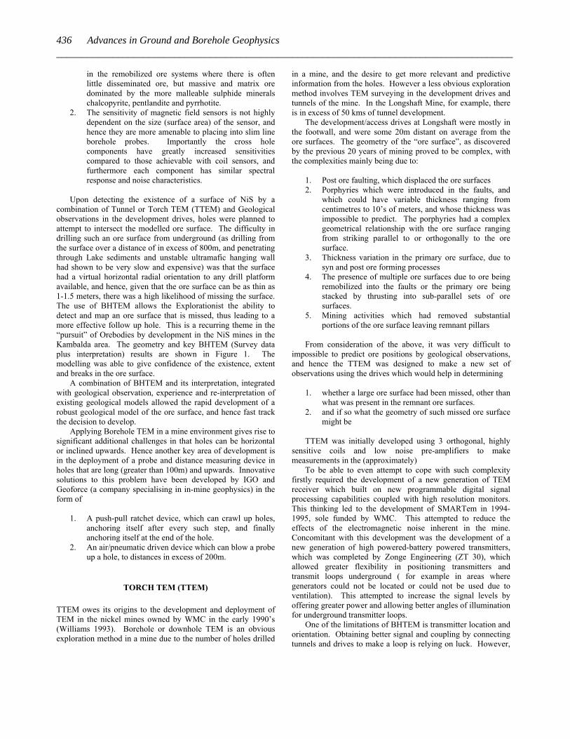
Figure 1: Use of the 3 component fluxgate BHTEM probe in the discovery and delineation of the McLeay NiS Orebody. The left hand panel shows a plan view with the dark brown being the tunnels used for access to the Orebody; the black squares represent individual reading points in 2 holes with flat trajectories striking south. The conductive plates used for modelling the BHTEM response are indicated by as the concentrically rib boned rectangles. The polygons (dark and light green) are geological estimates of the possible surfaces. The right hand panel shows the 3 component BHTEM response (Black is measured, red is modelled). The model predicts the extension of the mineralization beyond the geological model, and importantly a gap in the plates, which is now known t be a fault occupied by a felsic porphyry.
3. Compactness, which has the blessing of the probe being
shorter, narrower diameter and lighter. All of these characteristics being critical in the deployment in mines, where the holes are typically slim-line (40mm or less in diameter), and can be flat or inclined steeply upwards.
4. B-Field measurement are especially relevant to the search for highly conductive ore bodies like massive nickel sulphides, as they practically have a higher signal to noise. Early experiments showed that the highly conductive Orebodies had a reduced signal as detected by induction sensors.
5. Faster survey production rates The operational advantages of using this probe as well as the
Torch TEM system were quickly realized by the Independence Group, in the discovery of the McLeay Nickel Sulphide deposit (2004) and by Mincor, in the Kambalda Nickel Camp of Western Australia. To best illustrate the advances in TEM technology we focus on the discovery of the McLeay Nis deposit at Kambalda. These small but high grade deposits present a high degree of technical challenge to both explorers and miners. Finding them at 800 meters beneath a salt lake presents additional challenges.
Primary nickel sulphide ore in the Kambalda Nickel Camp is developed in small river like channels (Barnes 2006), at the basal contact between komaatiite flows and a footwall, which is often either basalt or felsic volcanics. The sulphides are highly malleable and can be squeezed and squirted into dilatational sites, which can be numerous in structurally complex areas, such as that of the Long-Victor mine, which is between the Boulder-Lefroy crustal scale fault and the Kambalda Dome. The
challenge is to be able to detect and map out those surfaces which are commercially significant and continuous) in the least amount of time. The Victor channel (Long shaft Mine, Kambalda – Australia) is a prime example as it is a sinuous channel which generally strikes N-NW, but in detail the mineralized surface can be convoluted and cut by faults and/or porphyry bodies, which can translate the surface vertically or horizontally, or even twist the surface.
The McLeay massive nickel sulphide deposit was discovered by the use of BHTEM in conjunction with Torch TEM (TTEM) and geological inference (Williams, Sheppard, Gibson, 2007). Motivation for such a methodology is introduced in Williams (1993), Trench and Williams (1994), Williams and Turner (1996) and Emerson, Martin and Williams (1997), and stems from the fact that massive and matrix nickel sulphide ores are one of the most conductive ores in the world. This has two significant inferences in the use of TEM in near or in-mine environments for massive Nickel Sulphide Ores.
1. The off-time TEM response of such highly conductive
ore is governed by the fact that there is little decay of the induced current systems, and hence very little decay in the secondary magnetic field, but there can be a relatively appreciable magnetic field (which is directly proportional to the conductance of the ore). It follows that induction sensors, which measure the decay of the secondary magnetic field can be dealing with low S/N signal, a problem compounded by the increase in radiated noise due to equipment, communications and power supplies in or near a mine. Magnetic sensors which measure the induced current system directly provide a better means of detecting and mapping such highly conductive ore systems. This is especially true
435Williams, P.K., et al. Innovative EM exploration in exploration and mine settings __________________________________________________________________________________________
in the remobilized ore systems where there is often little disseminated ore, but massive and matrix ore dominated by the more malleable sulphide minerals chalcopyrite, pentlandite and pyrrhotite.
2. The sensitivity of magnetic field sensors is not highly dependent on the size (surface area) of the sensor, and hence they are more amenable to placing into slim line borehole probes. Importantly the cross hole components have greatly increased sensitivities compared to those achievable with coil sensors, and furthermore each component has similar spectral response and noise characteristics.
Upon detecting the existence of a surface of NiS by a
combination of Tunnel or Torch TEM (TTEM) and Geological observations in the development drives, holes were planned to attempt to intersect the modelled ore surface. The difficulty in drilling such an ore surface from underground (as drilling from the surface over a distance of in excess of 800m, and penetrating through Lake sediments and unstable ultramafic hanging wall had shown to be very slow and expensive) was that the surface had a virtual horizontal radial orientation to any drill platform available, and hence, given that the ore surface can be as thin as 1-1.5 meters, there was a high likelihood of missing the surface. The use of BHTEM allows the Explorationist the ability to detect and map an ore surface that is missed, thus leading to a more effective follow up hole. This is a recurring theme in the “pursuit” of Orebodies by development in the NiS mines in the Kambalda area. The geometry and key BHTEM (Survey data plus interpretation) results are shown in Figure 1. The modelling was able to give confidence of the existence, extent and breaks in the ore surface.
A combination of BHTEM and its interpretation, integrated with geological observation, experience and re-interpretation of existing geological models allowed the rapid development of a robust geological model of the ore surface, and hence fast track the decision to develop.
Applying Borehole TEM in a mine environment gives rise to significant additional challenges in that holes can be horizontal or inclined upwards. Hence another key area of development is in the deployment of a probe and distance measuring device in holes that are long (greater than 100m) and upwards. Innovative solutions to this problem have been developed by IGO and Geoforce (a company specialising in in-mine geophysics) in the form of
1. A push-pull ratchet device, which can crawl up holes,
anchoring itself after every such step, and finally anchoring itself at the end of the hole.
2. An air/pneumatic driven device which can blow a probe up a hole, to distances in excess of 200m.
TORCH TEM (TTEM) TTEM owes its origins to the development and deployment of TEM in the nickel mines owned by WMC in the early 1990’s (Williams 1993). Borehole or downhole TEM is an obvious exploration method in a mine due to the number of holes drilled
in a mine, and the desire to get more relevant and predictive information from the holes. However a less obvious exploration method involves TEM surveying in the development drives and tunnels of the mine. In the Longshaft Mine, for example, there is in excess of 50 kms of tunnel development.
The development/access drives at Longshaft were mostly in the footwall, and were some 20m distant on average from the ore surfaces. The geometry of the “ore surface”, as discovered by the previous 20 years of mining proved to be complex, with the complexities mainly being due to:
1. Post ore faulting, which displaced the ore surfaces 2. Porphyries which were introduced in the faults, and
which could have variable thickness ranging from centimetres to 10’s of meters, and whose thickness was impossible to predict. The porphyries had a complex geometrical relationship with the ore surface ranging from striking parallel to or orthogonally to the ore surface.
3. Thickness variation in the primary ore surface, due to syn and post ore forming processes
4. The presence of multiple ore surfaces due to ore being remobilized into the faults or the primary ore being stacked by thrusting into sub-parallel sets of ore surfaces.
5. Mining activities which had removed substantial portions of the ore surface leaving remnant pillars
From consideration of the above, it was very difficult to
impossible to predict ore positions by geological observations, and hence the TTEM was designed to make a new set of observations using the drives which would help in determining
1. whether a large ore surface had been missed, other than
what was present in the remnant ore surfaces. 2. and if so what the geometry of such missed ore surface
might be TTEM was initially developed using 3 orthogonal, highly
sensitive coils and low noise pre-amplifiers to make measurements in the (approximately)
To be able to even attempt to cope with such complexity firstly required the development of a new generation of TEM receiver which built on new programmable digital signal processing capabilities coupled with high resolution monitors. This thinking led to the development of SMARTem in 1994-1995, sole funded by WMC. This attempted to reduce the effects of the electromagnetic noise inherent in the mine. Concomitant with this development was the development of a new generation of high powered-battery powered transmitters, which was completed by Zonge Engineering (ZT 30), which allowed greater flexibility in positioning transmitters and transmit loops underground ( for example in areas where generators could not be located or could not be used due to ventilation). This attempted to increase the signal levels by offering greater power and allowing better angles of illumination for underground transmitter loops.
One of the limitations of BHTEM is transmitter location and orientation. Obtaining better signal and coupling by connecting tunnels and drives to make a loop is relying on luck. However,
436 Advances in Ground and Borehole Geophysics_________________________________________________________________________________________
means that an approach similar to a helicopter-borne TEM (e.g. VTEM or NEWTEM) system might be useful.
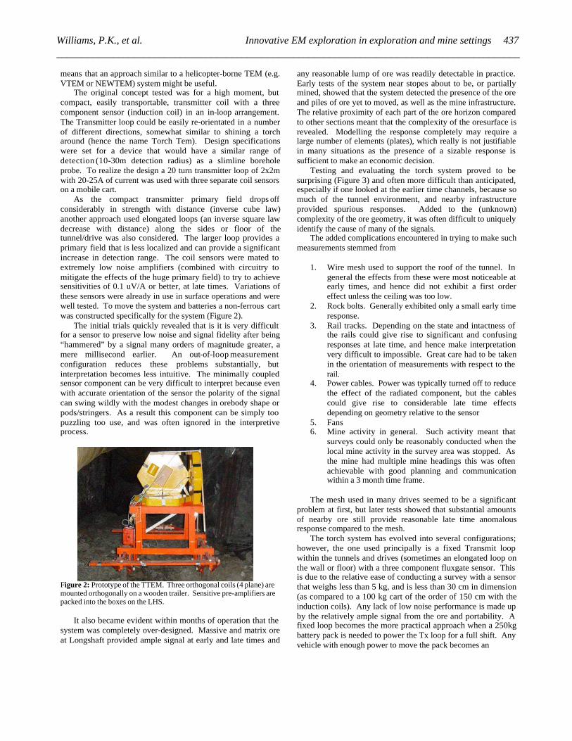
The original concept tested was for a high moment, but compact, easily transportable, transmitter coil with a three component sensor (induction coil) in an in-loop arrangement. The Transmitter loop could be easily re-orientated in a number of different directions, somewhat similar to shining a torch around (hence the name Torch Tem). Design specifications were set for a device that would have a similar range of detection (10-30m detection radius) as a slimline borehole probe. To realize the design a 20 turn transmitter loop of 2x2m with 20-25A of current was used with three separate coil sensors on a mobile cart.
As the compact transmitter primary field drops off considerably in strength with distance (inverse cube law) another approach used elongated loops (an inverse square law decrease with distance) along the sides or floor of the tunnel/drive was also considered. The larger loop provides a primary field that is less localized and can provide a significant increase in detection range. The coil sensors were mated to extremely low noise amplifiers (combined with circuitry to mitigate the effects of the huge primary field) to try to achieve sensitivities of 0.1 uV/A or better, at late times. Variations of these sensors were already in use in surface operations and were well tested. To move the system and batteries a non-ferrous cart was constructed specifically for the system (Figure 2).
The initial trials quickly revealed that is it is very difficult for a sensor to preserve low noise and signal fidelity after being “hammered” by a signal many orders of magnitude greater, a mere millisecond earlier. An out-of-loop measurement configuration reduces these problems substantially, but interpretation becomes less intuitive. The minimally coupled sensor component can be very difficult to interpret because even with accurate orientation of the sensor the polarity of the signal can swing wildly with the modest changes in orebody shape or pods/stringers. As a result this component can be simply too puzzling too use, and was often ignored in the interpretive process.
Figure 2: Prototype of the TTEM. Three orthogonal coils (4 plane) are mounted orthogonally on a wooden trailer. Sensitive pre-amplifiers are packed into the boxes on the LHS.
It also became evident within months of operation that the
system was completely over-designed. Massive and matrix ore at Longshaft provided ample signal at early and late times and
any reasonable lump of ore was readily detectable in practice. Early tests of the system near stopes about to be, or partially mined, showed that the system detected the presence of the ore and piles of ore yet to moved, as well as the mine infrastructure. The relative proximity of each part of the ore horizon compared to other sections meant that the complexity of the oresurface is revealed. Modelling the response completely may require a large number of elements (plates), which really is not justifiable in many situations as the presence of a sizable response is sufficient to make an economic decision.
Testing and evaluating the torch system proved to be surprising (Figure 3) and often more difficult than anticipated, especially if one looked at the earlier time channels, because so much of the tunnel environment, and nearby infrastructure provided spurious responses. Added to the (unknown) complexity of the ore geometry, it was often difficult to uniquely identify the cause of many of the signals.
The added complications encountered in trying to make such measurements stemmed from
1. Wire mesh used to support the roof of the tunnel. In
general the effects from these were most noticeable at early times, and hence did not exhibit a first order effect unless the ceiling was too low.
2. Rock bolts. Generally exhibited only a small early time response.
3. Rail tracks. Depending on the state and intactness of the rails could give rise to significant and confusing responses at late time, and hence make interpretation very difficult to impossible. Great care had to be taken in the orientation of measurements with respect to the rail.
4. Power cables. Power was typically turned off to reduce the effect of the radiated component, but the cables could give rise to considerable late time effects depending on geometry relative to the sensor
5. Fans 6. Mine activity in general. Such activity meant that
surveys could only be reasonably conducted when the local mine activity in the survey area was stopped. As the mine had multiple mine headings this was often achievable with good planning and communication within a 3 month time frame.
The mesh used in many drives seemed to be a significant
problem at first, but later tests showed that substantial amounts of nearby ore still provide reasonable late time anomalous response compared to the mesh.
The torch system has evolved into several configurations; however, the one used principally is a fixed Transmit loop within the tunnels and drives (sometimes an elongated loop on the wall or floor) with a three component fluxgate sensor. This is due to the relative ease of conducting a survey with a sensor that weighs less than 5 kg, and is less than 30 cm in dimension (as compared to a 100 kg cart of the order of 150 cm with the induction coils). Any lack of low noise performance is made up by the relatively ample signal from the ore and portability. A fixed loop becomes the more practical approach when a 250kg battery pack is needed to power the Tx loop for a full shift. Any vehicle with enough power to move the pack becomes an
437Williams, P.K., et al. Innovative EM exploration in exploration and mine settings __________________________________________________________________________________________
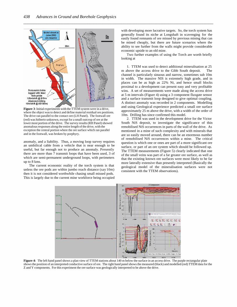
Figure 3: Initial experiments with the TTEM system were in a drive, where the object was to detect and define material residual ore positions. The drive ran parallel to the contact ore (LH Panel). The footwall ore (red) was hitherto unknown, except for a small outcrop of ore at the lower most portion of the drive. The survey results (RH Panel) showed anomalous responses along the entire length of the drive, with the exception the central portion where the ore surface which ran parallel and in the footwall, was broken by porphyry. anomaly, and a liability. Thus, a moving loop survey requires an umbilical cable from a vehicle that is near enough to be useful, but far enough not to produce an anomaly. Presently there are more than 7 transmit loops that have been used, 3 of which are semi-permanent underground loops, with perimeters up to 8 kms.
The current economic reality of the torch system is that unless the ore pods are within jumbo reach distance (say 10m) then it is not considered worthwhile chasing small missed pods. This is largely due to the current mine workforce being occupied
with developing more lucrative targets. So, the torch system has generally found its niche at Longshaft in scavenging for the easily found remnants of ore missed by previous mining that can be mined cheaply, but there are future scenarios where the ability to see further from the walls might provide considerable economic upside to an old mine.
Two further examples of using the Torch are worth briefly looking at
1. TTEM was used to detect additional mineralisation at 25
m above the access drive to the Gibb South deposit. The channel is particularly sinuous and narrow, sometimes sub 10m in width. The massive NIS is extremely high grade, and in places can be as high as 22% Ni, and hence small blocks proximal to a development can present easy and very profitable wins. A set of measurements were made along the access drive at 5 m intervals (Figure 4) using a 3 component fluxgate sensor and a surface transmit loop designed to give optimal coupling. A distinct anomaly was recorded in 2 components. Modelling and using Geological experience predicted a small ore surface approximately 25 m above the drive, with a width of the order of 10m. Drilling has since confirmed this model.
2. TTEM was used in the development drive for the Victor South NiS deposit, to investigate the significance of thin remobilised NiS occurrences in parts of the wall of the drive. As mentioned in a mine of such complexity and with minerals that are so easily moved around, there can be an enormous number of remobilised NiS occurrences within a mine. The critical question is which one or ones are part of a more significant ore surface, or part of an ore system which should be followed up. The TTEM measurements (Figure 5) clearly indicated that one of the small veins was part of a far greater ore surface, as well as that the existing known ore surfaces were most likely to be far more laterally extensive than presently interpreted (Basically the geological model of the mineralisation surfaces were not consistent with the TTEM observations).
Figure 4: The left hand panel shows a plan view of TTEM stations about 140 m below the surface in an access drive. The purple rectangular plate shows the position of an interpreted conductive surface of ore. The right hand panel shows the measured (black) and modelled (red) TTEM data for the Z and Y components. For this experiment the ore surface was geologically interpreted to be above the drive.
438 Advances in Ground and Borehole Geophysics_________________________________________________________________________________________
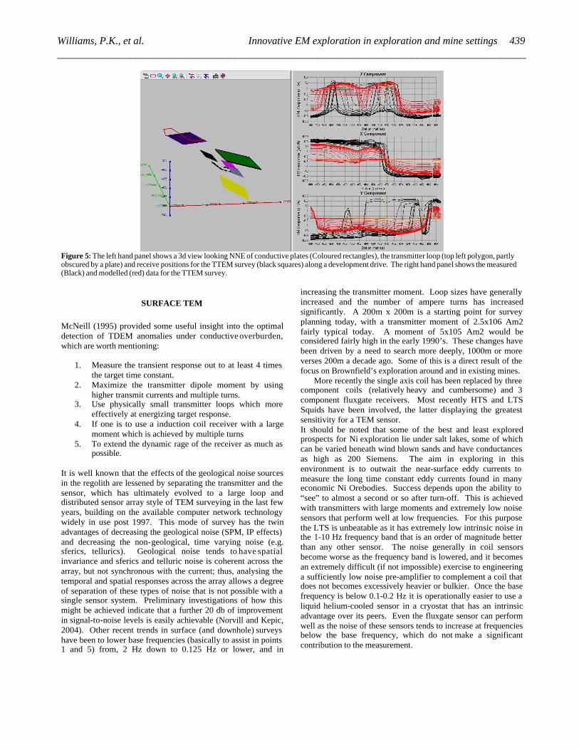
Figure 5: The left hand panel shows a 3d view looking NNE of conductive plates (Coloured rectangles), the transmitter loop (top left polygon, partly obscured by a plate) and receive positions for the TTEM survey (black squares) along a development drive. The right hand panel shows the measured (Black) and modelled (red) data for the TTEM survey.
SURFACE TEM
McNeill (1995) provided some useful insight into the optimal detection of TDEM anomalies under conductive overburden, which are worth mentioning:
1. Measure the transient response out to at least 4 times the target time constant.
2. Maximize the transmitter dipole moment by using higher transmit currents and multiple turns.
3. Use physically small transmitter loops which more effectively at energizing target response.
4. If one is to use a induction coil receiver with a large moment which is achieved by multiple turns
5. To extend the dynamic rage of the receiver as much as possible.
It is well known that the effects of the geological noise sources in the regolith are lessened by separating the transmitter and the sensor, which has ultimately evolved to a large loop and distributed sensor array style of TEM surveying in the last few years, building on the available computer network technology widely in use post 1997. This mode of survey has the twin advantages of decreasing the geological noise (SPM, IP effects) and decreasing the non-geological, time varying noise (e.g. sferics, tellurics). Geological noise tends to have spatial invariance and sferics and telluric noise is coherent across the array, but not synchronous with the current; thus, analysing the temporal and spatial responses across the array allows a degree of separation of these types of noise that is not possible with a single sensor system. Preliminary investigations of how this might be achieved indicate that a further 20 db of improvement in signal-to-noise levels is easily achievable (Norvill and Kepic, 2004). Other recent trends in surface (and downhole) surveys have been to lower base frequencies (basically to assist in points 1 and 5) from, 2 Hz down to 0.125 Hz or lower, and in
increasing the transmitter moment. Loop sizes have generally increased and the number of ampere turns has increased significantly. A 200m x 200m is a starting point for survey planning today, with a transmitter moment of 2.5x10⁶ Am2 fairly typical today. A moment of 5x10⁵ Am2 would be considered fairly high in the early 1990’s. These changes have been driven by a need to search more deeply, 1000m or more verses 200m a decade ago. Some of this is a direct result of the focus on Brownfield’s exploration around and in existing mines.
More recently the single axis coil has been replaced by three component coils (relatively heavy and cumbersome) and 3 component fluxgate receivers. Most recently HTS and LTS Squids have been involved, the latter displaying the greatest sensitivity for a TEM sensor. It should be noted that some of the best and least explored prospects for Ni exploration lie under salt lakes, some of which can be varied beneath wind blown sands and have conductances as high as 200 Siemens. The aim in exploring in this environment is to outwait the near-surface eddy currents to measure the long time constant eddy currents found in many economic Ni Orebodies. Success depends upon the ability to “see” to almost a second or so after turn-off. This is achieved with transmitters with large moments and extremely low noise sensors that perform well at low frequencies. For this purpose the LTS is unbeatable as it has extremely low intrinsic noise in the 1-10 Hz frequency band that is an order of magnitude better than any other sensor. The noise generally in coil sensors become worse as the frequency band is lowered, and it becomes an extremely difficult (if not impossible) exercise to engineering a sufficiently low noise pre-amplifier to complement a coil that does not becomes excessively heavier or bulkier. Once the base frequency is below 0.1-0.2 Hz it is operationally easier to use a liquid helium-cooled sensor in a cryostat that has an intrinsic advantage over its peers. Even the fluxgate sensor can perform well as the noise of these sensors tends to increase at frequencies below the base frequency, which do not make a significant contribution to the measurement.
439Williams, P.K., et al. Innovative EM exploration in exploration and mine settings __________________________________________________________________________________________
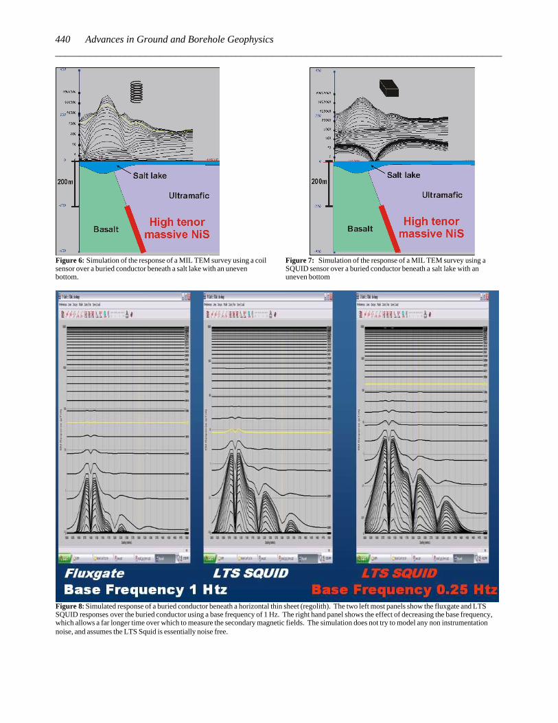
Figure 6: Simulation of the response of a MIL TEM survey using a coil sensor over a buried conductor beneath a salt lake with an uneven bottom.
Figure 7: Simulation of the response of a MIL TEM survey using a SQUID sensor over a buried conductor beneath a salt lake with an uneven bottom
Figure 8: Simulated response of a buried conductor beneath a horizontal thin sheet (regolith). The two left most panels show the fluxgate and LTS SQUID responses over the buried conductor using a base frequency of 1 Hz. The right hand panel shows the effect of decreasing the base frequency, which allows a far longer time over which to measure the secondary magnetic fields. The simulation does not try to model any non instrumentation noise, and assumes the LTS Squid is essentially noise free.
440 Advances in Ground and Borehole Geophysics_________________________________________________________________________________________
The follow up geometry of a Fixed Loop TEM survey has been preferred when there is reasonable control on the geometry of the feature to be prospected. This style of survey which started with a single transmitter and single receiver has now broadened using Wide Area Computer networking concepts and technology to include arrays of sensors, all measuring on a common time base. The sensors again can be magnetometers or coils. An interesting variant which was first devised by WMC in the mid 1980’s has been Absolute Phase Magnetometric Resisitivity and IP. This has now involved into the SAM technique which uses a total field magnetometer as a sensor, and a grounded electrode as the transmitter.
SUMMARY
Development pre-1997 followed along the path of successive adaptations of Russian built TEM instrumentation to a hostile geological environment. Focus wavered from reducing external noise to attempting to reduce the effects of geological noise, principally sourced in the regolith as a result of lateritisation. In the mid 1990’s instrumentation started to build on computer technology, allowing for digital filtering and improved graphical displays in the field.
In the period 1997 to 2007, the main drivers in the advancement of TEM surveying has been
1. Adoption of the networking technology in computers to
allow multiple sensor arrays to be laid out efficiently and effectively, which allows Wide area network fixed loop surveys. This has the advantages in lateritic terrains of reducing the geological noise from the regolith, as well as more effectively reducing time dependent noise in the survey.
2. An increase in moment of a new generation of transmitters, allowing higher currents to be used to increase the transmitter moment and hence geological signal.
3. The emergence of ultra low noise LTS SQUID sensors as operationally effective sensors for surface TEM surveys
4. The emergence of a 3 component fluxgate sensor in bore hole TEM surveying which has allowed for slimmer, shorter and lighter probes, which are especially important in the mine environment
5. The successful use of an adaptation of the borehole TEM, being used in tunnels and drives (TTEM).
Looking forward, one of the main goals is to design a new
low cost, low noise magnetic sensor which does not require the logistical support needed for the LT SQUID, and hence can be used as a sensor in the distributed array style of TEM surveying. The present array style surveying will continue to evolve to become more operationally efficient and robust. New processing algorithms which take full advantage of the distributed sensors array will develop and become operational as increases in computer speed and more compact designs become available. The LT Squid may well find its optimal place as a
base station for this style of surveying due to its very low noise characteristics.
REFERENCES
Barnes, S. J. (ED), 2006, Nickel Deposits of the Yilgarn Craton, Special
Publication 13, Soc. Of Econ. Geol., 210 pp.
Becker, A. and G. Cheng, 1987, Detection of Repetitive Electromagnetic Signals, Investigations in Geophysics No3, Vol 1, Ed Nabighian, M. N., Soc. of Explor. Geophysics
Bueselli, G. and B O’Neill, 1977, SIROTEM. A new portable instrument for multichannel transient electromagnetic measurements: Bull., Austral. Soc. Explor. Geophys. 8, 82-87.
Bueselli, G.., 1982, The effect of near surface superparamagnetic material on electromagnetic measurements; Geophysics, 47, 1315-1324.
Donohue, J. G. and S. N. Sheard, 2001, Geophysics in North West Queensland – Improving the use of electrical geophysics, v1, 1-6.
Duncan, A., Williams, P. K., Turner, G., Fraser, G. A., Martin, K, and Wellington, A., 1997: SMARTem: A new electrical methods receiver system, Preview 67, (26-29)
Duncan, A., Williams, P. K, Turner, G., Amann, W, Tully, T., O'Keeffe, K . a n d Wellington, A., 1997: Examples from a new electromagnetic and electrical methods receiver system, Exploration Geophysics 29, (347-354).
Flis, M. F., Newman, G. A and G. W. Hohman, 1989, Induced Polarisation effects in time domain electromagnetic measurements: Geophysics, 54, 524-523.
Emerson, D., Turner, G. and Williams P., 1998. P wave velocities of ores in komatiitic nickel sulphide deposits: ASEG Preview 74, (28-33).
Emerson, D. W., Martin, K and P. K. Williams, 1999, Electrical, Magnetic and Mass Properties of the Nickeliferous Komatiite Sequence near Leinster, Western Australia; “The Rock Doctor”, Preview, 81, 13-21.
Macnae, J. C., Lamontagne, Y., and G. F West, 1984, Noise Processing Techniques for time domain EM systems, Geophys, Vol. 9 (7) p 934-948.
McCracken K. G., Oristaglio, M. L., and G. W. Hohman, 1986, A comparison of Electromagnetic Systems, Geophys Vol. 51 (3), p 810-818.
McCracken, K. G., Pik, J. P. and R. W. Harris, 1984, Noise in EM Exploration Systems, Explor. Geophys. Vol 15, p169-174.
McNeil, J. D., 1995, The Optimal Detection of TDEM Anomalies under conductive overburden, Geonics Technical Note TN-28.
Norvill, M., and Kepic, A., 2004, Improving signal-to-noise in electrical and EM methods with sensor arrays: Expanded Abstract Presented at the EAGE Near Surface 2004 10th European Meeting of Environmental and Engineering Geophysics, Utrecht, The Netherlands .
Peters, W. S. 2006, Geophysical exploration for Nickel Sulphide Mineralisation in the Yilgarn Craton, Western Australia in Barnes, S. J. (ED), 2006, Nickel Deposits of the Yilgarn Craton, Special Publication 13., Soc. Of Econ. Geol., 210 pp.
441Williams, P.K., et al. Innovative EM exploration in exploration and mine settings __________________________________________________________________________________________

Trench, A and P. K. Williams, 1994, Applications of Geophysics to nickel Sulphide Exploration, in the Kambalda District, Western Australia, in Francombe (et al., )Geophysical Signatures of Western Australian Mineral Deposits, Exploration geophysics, 169-179.
Williams P. K. and F. W. Lindeman, 1989, A compilation and analysis of SPM effects in TEM surveys in Australia and Brazil, WMC K Rpt 142.
Williams, P. K., 1993, In Mine Geophysics- A question of value, AMIRA Conference, Kalgoorlie, Western Australia.
Williams, P. K. and Turner G., 1996. Using geophysics in underground hard rock mining: A question of value and vision: Proceedings of the workshop on the role of in-mine geophysics in resource evaluation at the Sixty-Sixth Annual SEG meeting (30 pages).
Williams P. K., Sheppard S. S and L. M. Gibson, 2007, The discovery of the McLeay massive NiS Deposit, Kamabalda, Western Australia (in press).
442 Advances in Ground and Borehole Geophysics_________________________________________________________________________________________
Related Documents


![Development Consent [Underground Mine]](https://static.cupdf.com/doc/110x72/61c702ed978fda1722432dcf/development-consent-underground-mine.jpg)