Centre of Excellence for Nuclear Materials Workshop Materials Innovation for Nuclear Optimized Systems December 5-7, 2012, CEA – INSTN Saclay, France Laurent CHAFFRON et al. CEA (France) Innovative SiC/SiC Composite for Nuclear Applications Workshop organized by: Christophe GALLÉ, CEA/MINOS, Saclay – [email protected] Constantin MEIS, CEA/INSTN, Saclay – [email protected] Article available at http://www.epj-conferences.org or http://dx.doi.org/10.1051/epjconf/20135101003

Welcome message from author
This document is posted to help you gain knowledge. Please leave a comment to let me know what you think about it! Share it to your friends and learn new things together.
Transcript

Centre of Excellence for Nuclear Materials
Workshop Materials Innovation for Nuclear Optimized Systems
December 5-7, 2012, CEA – INSTN Saclay, France
Laurent CHAFFRON et al. CEA (France)
Innovative SiC/SiC Composite for Nuclear Applications
Workshop organized by:
Christophe GALLÉ, CEA/MINOS, Saclay – [email protected]
Constantin MEIS, CEA/INSTN, Saclay – [email protected]
Article available at http://www.epj-conferences.org or http://dx.doi.org/10.1051/epjconf/20135101003
Workshop Materials Innovation for Nuclear Optimized Systems December 5-7, 2012, CEA – INSTN Saclay, France
Innovative SiC/SiC Composite for Nuclear Applications
Laurent CHAFFRON1, Cédric SAUDER1, Christophe LORRETTE1, Laurent BRIOTTET2, Aurore MICHAUX1, Lionel GÉLÉBART1, Aurélie COUPÉ1, Maxime ZABIEGO3,
Marion LE FLEM1, Jean-Louis SÉRAN1 1CEA-DEN-DMN, Service de Recherche Métallurgiques Appliquées, SRMA (Saclay, France)
2 CEA-DRT, Laboratoires d’Innovation pour les Technologies des Energies, LITEN (Grenoble, France) 3 CEA-DEN-DEC, Service d’Etudes et de Simulation du Comportement des Combustibles, SESC (Cadarache, France)
Among various refractory materials, SiC/SiC ceramic matrix composites (CMC) are of prime interest for fusion and advanced fission energy applications, due to their excellent irradiation tolerance and safety features (low activation, low tritium permeability,…). Initially developed as fuel cladding materials for the Fourth generation Gas cooled Fast Reactor (GFR), this material has been recently envisaged by CEA for different core structures of Sodium Fast Reactor (SFR) which combines fast neutrons and high temperature (500°C). Regarding fuel cladding generic application, in the case of GFR, the first challenge facing this project is to demonstrate the feasibility of a fuel operating under very harsh conditions that are (i) temperatures of structures up to 700°C in nominal and over 1600°C in accidental conditions, (ii) irradiation damage higher than 60 dpaSiC, (iii) neutronic transparency, which disqualifies conventional refractory metals as structural core materials, (iv) mechanical
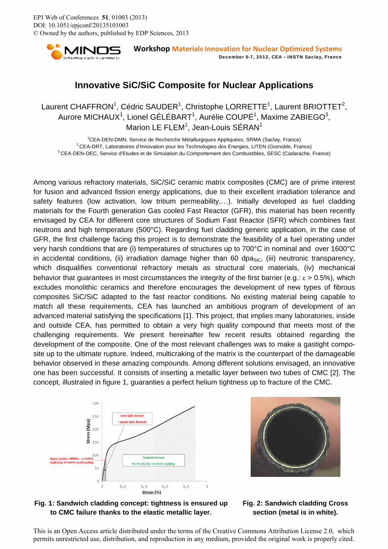
behavior that guarantees in most circumstances the integrity of the first barrier (e.g.: > 0.5%), which excludes monolithic ceramics and therefore encourages the development of new types of fibrous composites SiC/SiC adapted to the fast reactor conditions. No existing material being capable to match all these requirements, CEA has launched an ambitious program of development of an advanced material satisfying the specifications [1]. This project, that implies many laboratories, inside and outside CEA, has permitted to obtain a very high quality compound that meets most of the challenging requirements. We present hereinafter few recent results obtained regarding the development of the composite. One of the most relevant challenges was to make a gastight compo-site up to the ultimate rupture. Indeed, multicraking of the matrix is the counterpart of the damageable behavior observed in these amazing compounds. Among different solutions envisaged, an innovative one has been successful. It consists of inserting a metallic layer between two tubes of CMC [2]. The concept, illustrated in figure 1, guaranties a perfect helium tightness up to fracture of the CMC.
Fig. 1: Sandwich cladding concept: tightness is ensured up to CMC failure thanks to the elastic metallic layer.
Fig. 2: Sandwich cladding Cross section (metal is in white).
EPJ Web of Conferences 51, 01003 (2013) DOI: 10.1051/epjconf/20135101003 © Owned by the authors, published by EDP Sciences, 2013
This is an Open Access article distributed under the terms of the Creative Commons Attribution License 2.0, which permits unrestricted use, distribution, and reproduction in any medium, provided the original work is properly cited.
Workshop Materials Innovation for Nuclear Optimized Systems December 5-7, 2012, CEA – INSTN Saclay, France
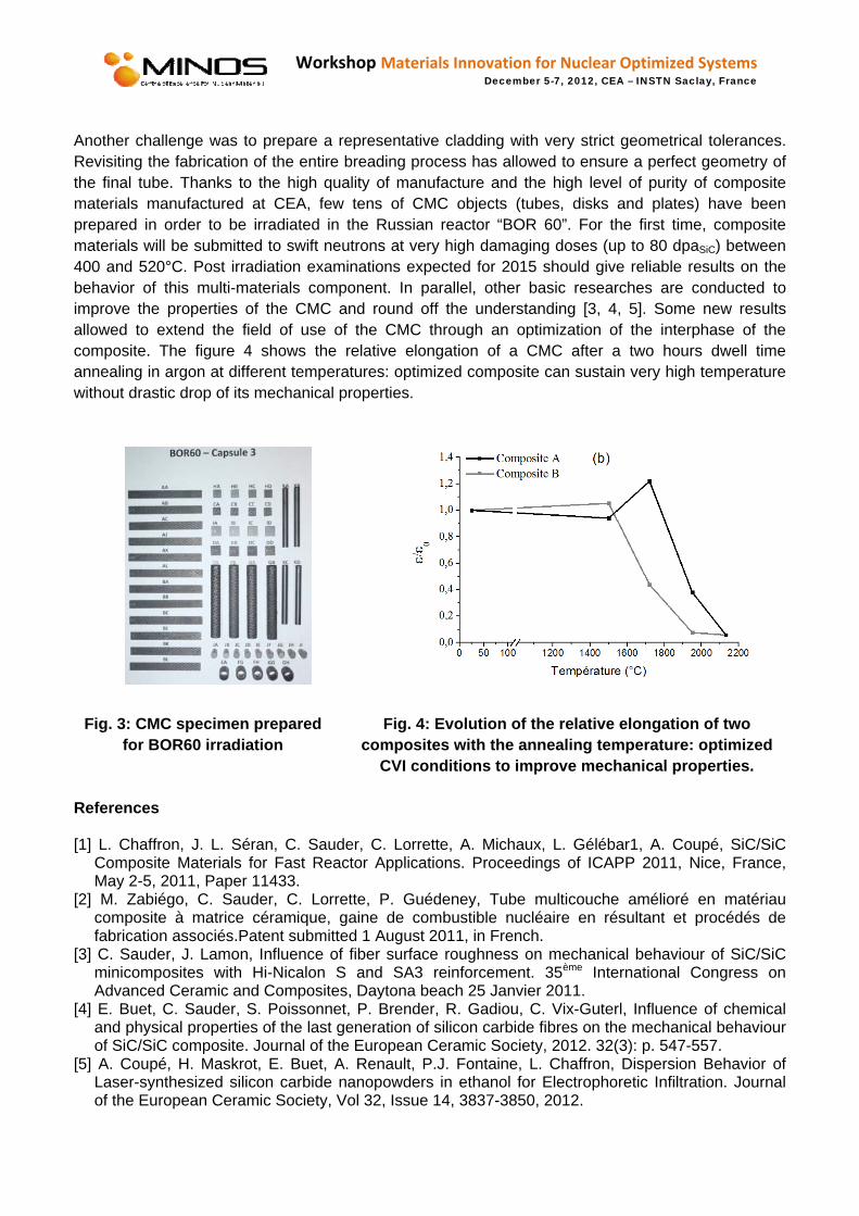
Another challenge was to prepare a representative cladding with very strict geometrical tolerances. Revisiting the fabrication of the entire breading process has allowed to ensure a perfect geometry of the final tube. Thanks to the high quality of manufacture and the high level of purity of composite materials manufactured at CEA, few tens of CMC objects (tubes, disks and plates) have been prepared in order to be irradiated in the Russian reactor “BOR 60”. For the first time, composite materials will be submitted to swift neutrons at very high damaging doses (up to 80 dpaSiC) between 400 and 520°C. Post irradiation examinations expected for 2015 should give reliable results on the behavior of this multi-materials component. In parallel, other basic researches are conducted to improve the properties of the CMC and round off the understanding [3, 4, 5]. Some new results allowed to extend the field of use of the CMC through an optimization of the interphase of the composite. The figure 4 shows the relative elongation of a CMC after a two hours dwell time annealing in argon at different temperatures: optimized composite can sustain very high temperature without drastic drop of its mechanical properties.
Fig. 3: CMC specimen prepared for BOR60 irradiation
Fig. 4: Evolution of the relative elongation of two composites with the annealing temperature: optimized
CVI conditions to improve mechanical properties.
References
[1] L. Chaffron, J. L. Séran, C. Sauder, C. Lorrette, A. Michaux, L. Gélébar1, A. Coupé, SiC/SiC Composite Materials for Fast Reactor Applications. Proceedings of ICAPP 2011, Nice, France, May 2-5, 2011, Paper 11433.
[2] M. Zabiégo, C. Sauder, C. Lorrette, P. Guédeney, Tube multicouche amélioré en matériau composite à matrice céramique, gaine de combustible nucléaire en résultant et procédés de fabrication associés.Patent submitted 1 August 2011, in French.
[3] C. Sauder, J. Lamon, Influence of fiber surface roughness on mechanical behaviour of SiC/SiC minicomposites with Hi-Nicalon S and SA3 reinforcement. 35ème International Congress on Advanced Ceramic and Composites, Daytona beach 25 Janvier 2011.
[4] E. Buet, C. Sauder, S. Poissonnet, P. Brender, R. Gadiou, C. Vix-Guterl, Influence of chemical and physical properties of the last generation of silicon carbide fibres on the mechanical behaviour of SiC/SiC composite. Journal of the European Ceramic Society, 2012. 32(3): p. 547-557.
[5] A. Coupé, H. Maskrot, E. Buet, A. Renault, P.J. Fontaine, L. Chaffron, Dispersion Behavior of Laser-synthesized silicon carbide nanopowders in ethanol for Electrophoretic Infiltration. Journal of the European Ceramic Society, Vol 32, Issue 14, 3837-3850, 2012.

Innovative SiC/SiC Composites for Nuclear Applications
21 NOVEMBER 2012
| PAGE 1CEA | 7 juin 2012
MINOS Workshop, Materials Innovation for Nuclear Optimized SystemsDecember 5-7, 2012, CEA – INSTN Saclay, France
C. Sauder, C. Lorrette, A. Michaux, L. Gélébart, E. Buet, S Poissonnet, A Coupé, J. Braun,
L Briottet, M. Zabiego, J.L. Séran, M. Le Flem,L. Chaffron
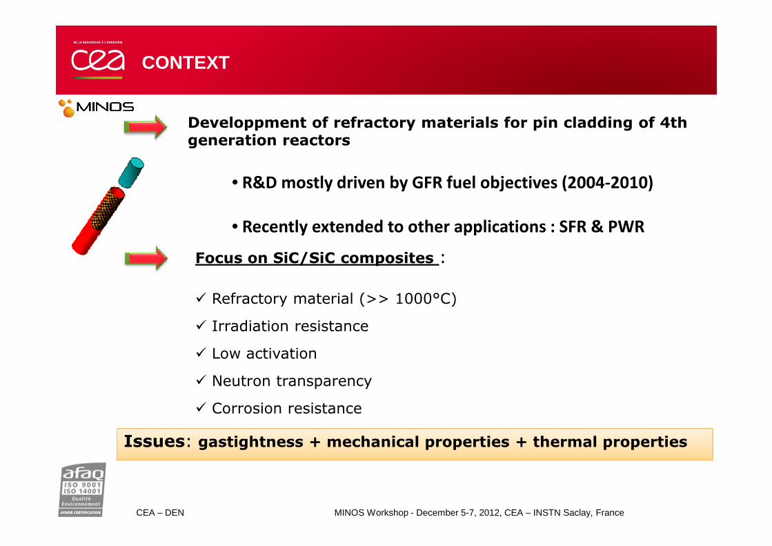
Developpment of refractory materials for pin cladding of 4th generation reactors
Focus on SiC/SiC composites :
CONTEXT
• R&D mostly driven by GFR fuel objectives (2004-2010)
• Recently extended to other applications : SFR & PWR
CEA – DEN MINOS Workshop - December 5-7, 2012, CEA – INSTN Saclay, France
� Refractory material (>> 1000°C)
� Irradiation resistance
� Low activation
� Neutron transparency
� Corrosion resistance
Issues: gastightness + mechanical properties + thermal properties
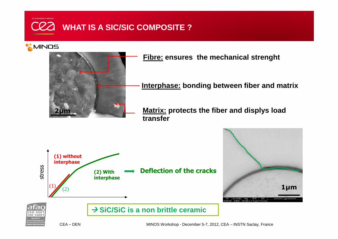
Matrix: protects the fiber and displys loadtransfer
Fibre: ensures the mechanical strenght
Interphase: bonding between fiber and matrix
2µm
WHAT IS A SIC/SIC COMPOSITE ?
CEA – DEN MINOS Workshop - December 5-7, 2012, CEA – INSTN Saclay, France
transfer
1µm
stress
(1) withoutinterphase
(1)(2)
(2) With interphase
Deflection of the cracks
���� SiC/SiC is a non brittle ceramic

WHICH SIC/SIC FOR NUCLEAR APPLICATION?
Choice of the fiber:
Stability under irradiation ⇒⇒⇒⇒
Hi-Nicalon S ou Tyranno SA3 fibers only
Stability at high temperature ⇒⇒⇒⇒
Tyranno SA3 fibers looks better
Thermal conductivity ⇒⇒⇒⇒
Tyranno SA3 fibers looks better
CEA – DEN MINOS Workshop - December 5-7, 2012, CEA – INSTN Saclay, France
Tyranno SA3 fibers looks better
Cost ⇒⇒⇒⇒Tyranno SA3 fiber is cheaper (30%)
HNS TSA3
Thermal stability
Thermal conductivity
Cost
Mechanical properties
Choice of the interphase: PyC
Choice of the matrix: SiC CVI
TSA TSA isis the the targettarget!!

THE MAIN CONCERNS FOR PIN CLADDING
FP retention= gas-thightness
Thermal exchange= High λ
Irradiation mechanical behavior
SiC/SiC is not gastight upon its linear elastic
domain.
λ SiC is lowered under irradiation (highly lowered at
low temperatures)
Strain to failure εR > 0,5%
CEA – DEN MINOS Workshop - December 5-7, 2012, CEA – INSTN Saclay, France | PAGE 5
domain. low temperatures)
Introduction of a liner for gas-tightness
=CEA sandwich concept
- Deal with it !- Use of SA3 reinforcement- Process a specific matrix
for composites⇒ very long term work
- Ok with HNS- No solutions with SA3- Look for high doseirradiated mechanicalbehavior.
Goal:� Development of a gastight component prepared from HNS SiC/SiCcomposite
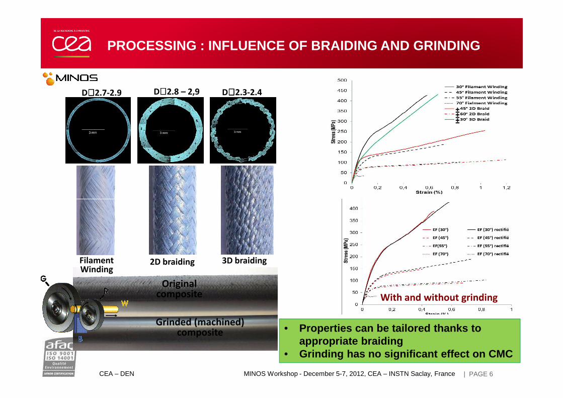
D∼∼∼∼ 2.7-2.9 D∼∼∼∼ 2.8 – 2,9 D∼∼∼∼ 2.3-2.4
±±±
PROCESSING : INFLUENCE OF BRAIDING AND GRINDING
CEA – DEN MINOS Workshop - December 5-7, 2012, CEA – INSTN Saclay, France | PAGE 6
Filament Winding
2D braiding 3D braiding
With and without grinding
Grinded (machined) composite
Original composite
• Properties can be tailored thanks to appropriate braiding
• Grinding has no significant effect on CMC

CHARACTERIZATION: WHICH TEMPERATURE LIMITATION?
Influence of a thermal treatment (2h in Ar) on mechanicalproperties
HNS tube
CEA – DEN MINOS Workshop - December 5-7, 2012, CEA – INSTN Saclay, France | PAGE 7
CVI SiC/SiC tube is not sensitive to very high temperaturein inert atmosphere
HNS fiber

Reference SiC/SiC material for Pin cladding :
FW (45°) 1 layer + 2D braiding (45°) 2 layers
mechanical behavior is the same for traction or internal
CHARACTERIZATION : FATIGUE
CEA – DEN MINOS Workshop - December 5-7, 2012, CEA – INSTN Saclay, France | PAGE 8
same for traction or internal swelling
Fatigue tests:20 -200MPa at 5 HzNo failure after 500 000 cycles!
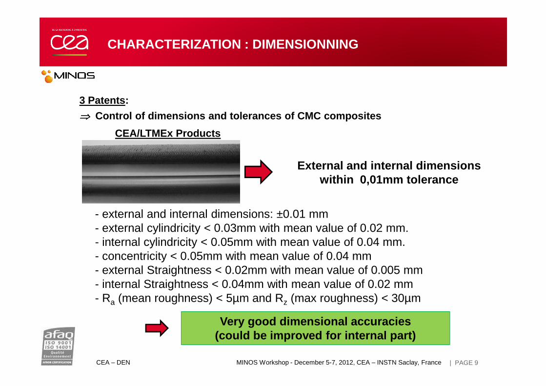
3 Patents :
⇒⇒⇒⇒ Control of dimensions and tolerances of CMC composites
CEA/LTMEx Products
External and internal dimensions within 0,01mm tolerance
CHARACTERIZATION : DIMENSIONNING
CEA – DEN MINOS Workshop - December 5-7, 2012, CEA – INSTN Saclay, France | PAGE 9
- external and internal dimensions: ±0.01 mm- external cylindricity < 0.03mm with mean value of 0.02 mm.- internal cylindricity < 0.05mm with mean value of 0.04 mm.- concentricity < 0.05mm with mean value of 0.04 mm- external Straightness < 0.02mm with mean value of 0.005 mm- internal Straightness < 0.04mm with mean value of 0.02 mm- Ra (mean roughness) < 5µm and Rz (max roughness) < 30µm
Very good dimensional accuracies (could be improved for internal part)

SiC/SiC CEA SiC CVD (R&H)
Purity of CEA SiC/SiCcomposites
CHARACTERIZATION: IMPURITIES CONCENTRATION
CEA – DEN MINOS Workshop - December 5-7, 2012, CEA – INSTN Saclay, France | PAGE 10
Very few impurities
Residual Impurities (Fe, S, N, O, H) belong to Hi-Nicalon S fibers
CEA | 21 Novembre 2012
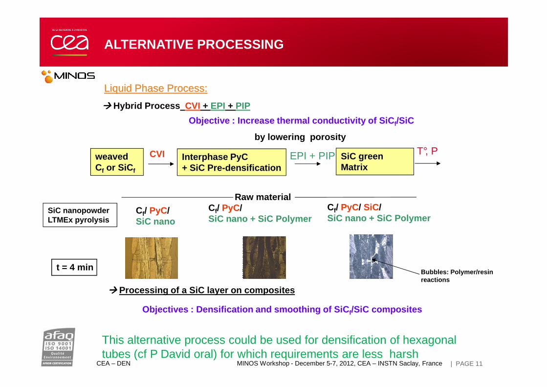
Liquid Phase Process:Liquid Phase Process:
���� Hybrid Process CVI + EPI + PIP
Objective : Increase thermal conductivity of SiC f/SiC
by lowering porosity
Raw material
weaved Cf or SiC f
CVI Interphase PyC+ SiC Pre-densification
EPI + PIP SiC green Matrix
T°, P
ALTERNATIVE PROCESSING
CEA – DEN MINOS Workshop - December 5-7, 2012, CEA – INSTN Saclay, France | PAGE 11
Cf/ PyC/ SiC nano
t = 4 min
Cf/ PyC/ SiC nano + SiC Polymer
Cf/ PyC/ SiC/SiC nano + SiC Polymer
SiC nanopowderLTMEx pyrolysis
���� Processing of a SiC layer on composites
Objectives : Densification and smoothing of SiC f/SiC composites
Bubbles: Polymer/resin reactions
Raw material
This alternative process could be used for densification of hexagonal tubes (cf P David oral) for which requirements are less harsh
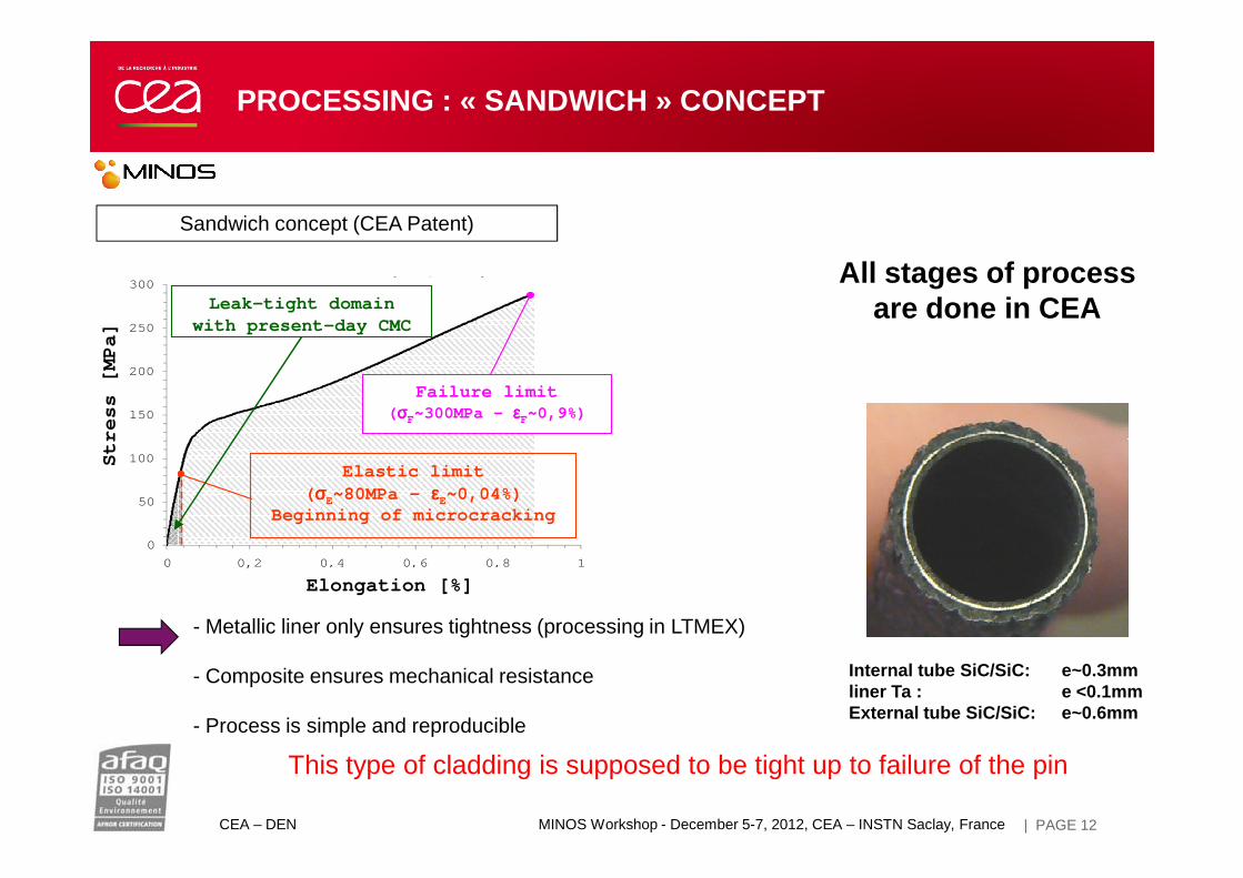
Sandwich concept (CEA Patent)
PROCESSING : « SANDWICH » CONCEPT
150
200
250
300
Con
train
te (
MP
a)
C. Sauder & C. Lorrette (CEA/DMN)
Leak-tight domainwith present-day CMC
Failure limit( σσσσF~300MPa - εεεεF~0,9%)
Str
ess
[M
Pa]
150
200
250
300
Con
train
te (
MP
a)
C. Sauder & C. Lorrette (CEA/DMN)
Leak-tight domainwith present-day CMC
Failure limit( σσσσF~300MPa - εεεεF~0,9%)
Str
ess
[M
Pa]
All stages of processare done in CEA
CEA – DEN MINOS Workshop - December 5-7, 2012, CEA – INSTN Saclay, France | PAGE 12
- Metallic liner only ensures tightness (processing in LTMEX)
- Composite ensures mechanical resistance
- Process is simple and reproducible
This type of cladding is supposed to be tight up to failure of the pin
Internal tube SiC/SiC: e~0.3mmliner Ta : e <0.1mmExternal tube SiC/SiC: e~0.6mm
0
50
100
0 0,2 0,4 0,6 0,8 1
Déformation (%)
Elastic limit( σσσσE~80MPa - εεεεE~0,04%)
Beginning of microcracking
Elongation [%]
Str
ess
[
0
50
100
0 0,2 0,4 0,6 0,8 1
Déformation (%)
Elastic limit( σσσσE~80MPa - εεεεE~0,04%)
Beginning of microcracking
Elongation [%]
Str
ess
[
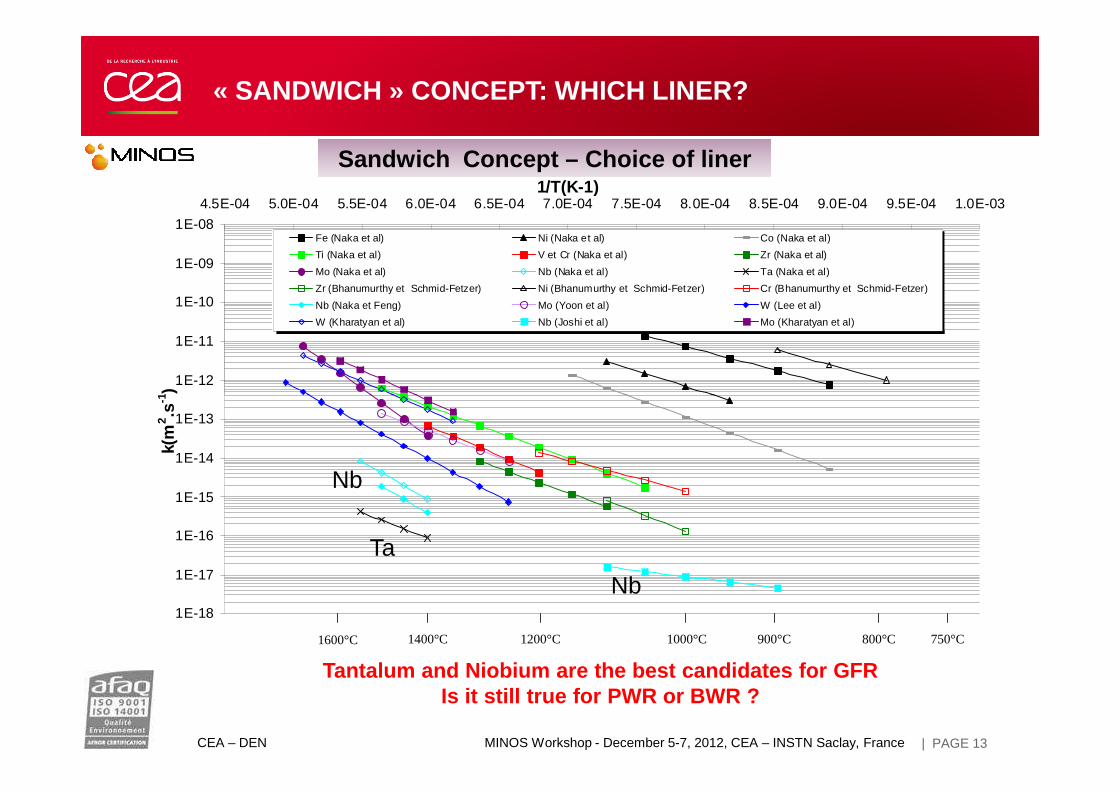
Sandwich Concept – Choice of liner
1E-12
1E-11
1E-10
1E-09
1E-08
4.5E-04 5.0E-04 5.5E-04 6.0E-04 6.5E-04 7.0E-04 7.5E-04 8.0E-04 8.5E-04 9.0E-04 9.5E-04 1.0E-031/T(K-1)
-1)
Fe (Naka et al) Ni (Naka et al) Co (Naka et al)
Ti (Naka et al) V et Cr (Naka et al) Zr (Naka et al)
Mo (Naka et al) Nb (Naka et al) Ta (Naka et al)
Zr (Bhanumurthy et Schmid-Fetzer) Ni (Bhanumurthy et Schmid-Fetzer) Cr (Bhanumurthy et Schmid-Fetzer)
Nb (Naka et Feng) Mo (Yoon et al) W (Lee et al)
W (Kharatyan et al) Nb (Joshi et al) Mo (Kharatyan et al)
« SANDWICH » CONCEPT: WHICH LINER?
CEA – DEN MINOS Workshop - December 5-7, 2012, CEA – INSTN Saclay, France | PAGE 13
Tantalum and Niobium are the best candidates for GFR Is it still true for PWR or BWR ?
1E-18
1E-17
1E-16
1E-15
1E-14
1E-13
k(m
2 .s-1
1600°C 1400°C 1200°C 1000°C 900°C 800°C 750°C
Ta
Nb
Nb

Sandwich Concept – tightness during tensile test
SANDWICH CHARACTERIZATION: PERMEATION
150
200
250
300
350
400
F/S
o (M
Pa)
1.0E-08
1.0E-07
1.0E-06
1.0E-05
1.0E-04
1.0E-03
1.0E-02
Déb
it (N
cm3/
s)
pression relative Hélium : 2 bar fin acquisition spectro en continu
acquisition uniquement aux palliers
CEA – DEN MINOS Workshop - December 5-7, 2012, CEA – INSTN Saclay, France | 14
Detection limit
« sandwich » concept allows to keep tightness up to failure of SiC/SiC pin cladding
0
50
100
0 2000 4000 6000 8000 10000 12000 14000
temps (s)
1.0E-11
1.0E-10
1.0E-09
1.0E-08
:
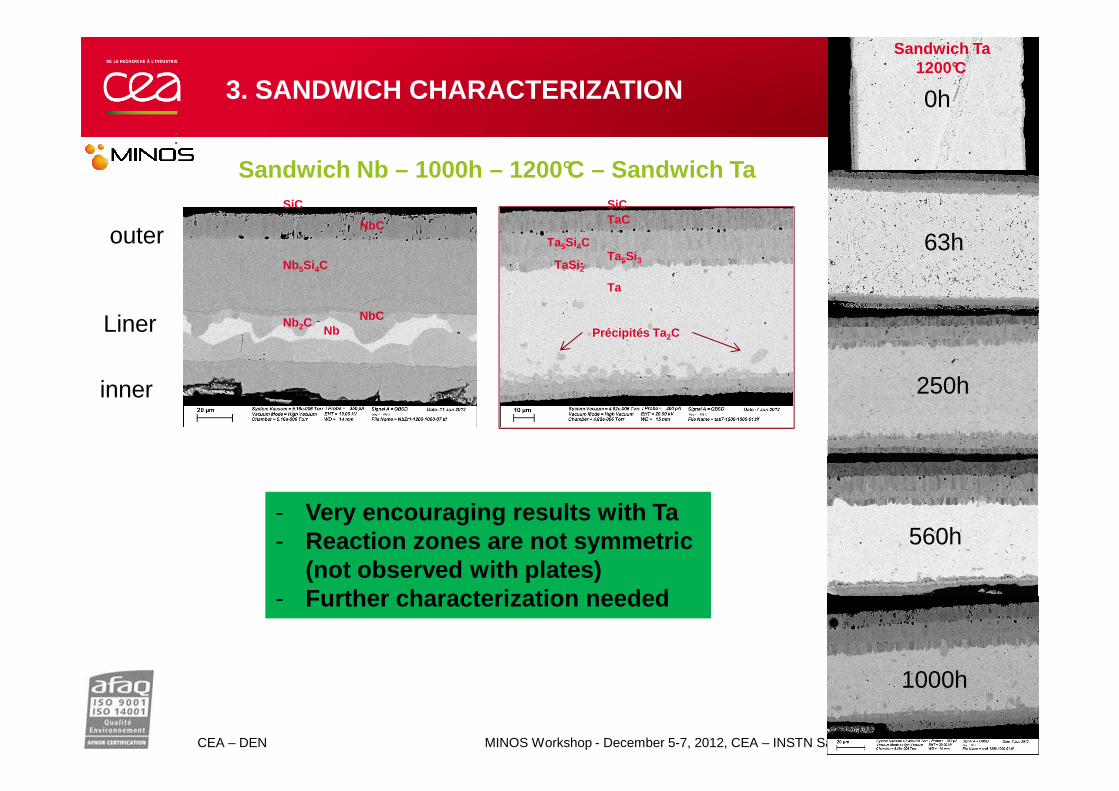
SiC
NbC
Nb5Si4C
NbCNb2C Nb
SiCTaC
Ta5Si4CTa5Si3TaSi2
Ta
Précipités Ta 2C
Sandwich Nb – 1000h – 1200°C – Sandwich Ta
0h
63h
250h
outer
Liner
Sandwich Ta1200°C
3. SANDWICH CHARACTERIZATION
inner
CEA – DEN MINOS Workshop - December 5-7, 2012, CEA – INSTN Saclay, France | PAGE 15
250h
560h
1000h
- Very encouraging results with Ta- Reaction zones are not symmetric
(not observed with plates)- Further characterization needed
inner
2. CHARACTERIZATION: IRRADIATION
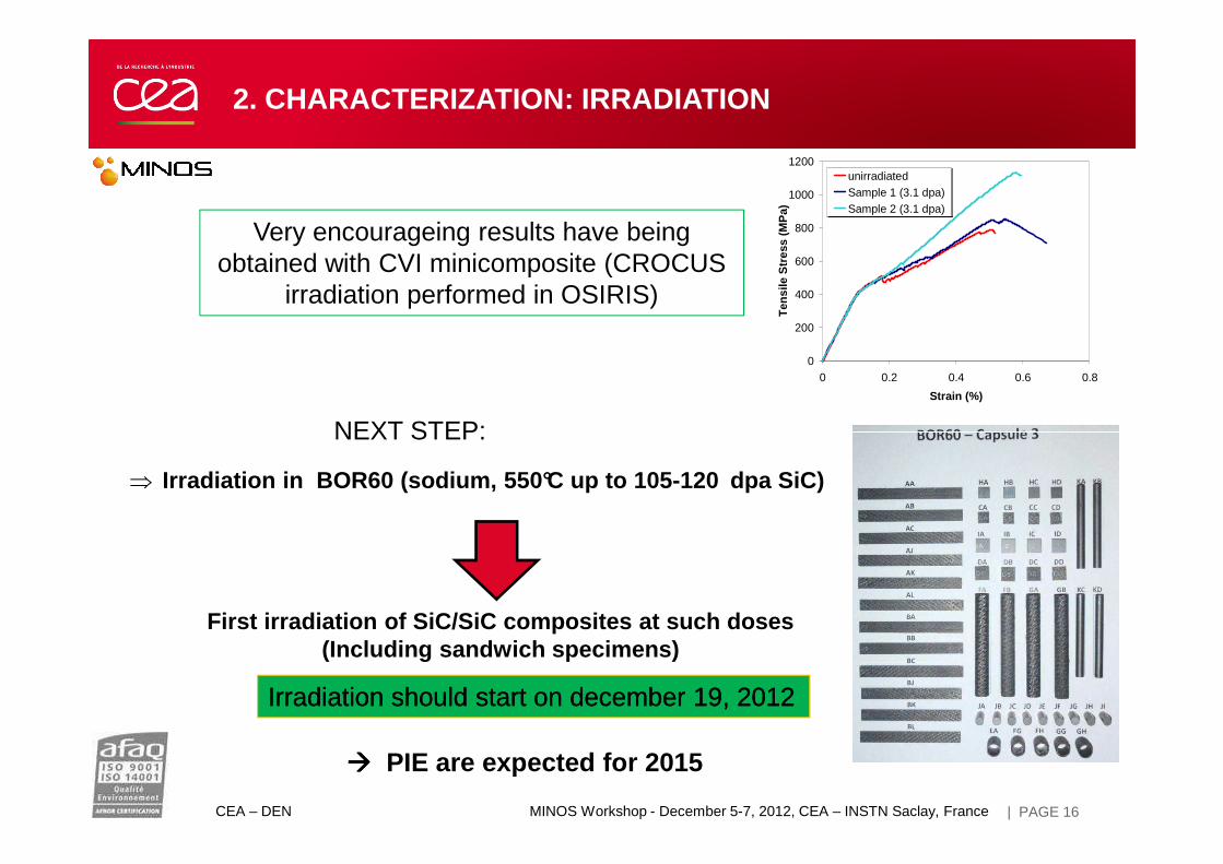
0
200
400
600
800
1000
1200
0 0.2 0.4 0.6 0.8
Strain (%)
Ten
sile
Str
ess
(MP
a)
unirradiatedSample 1 (3.1 dpa)Sample 2 (3.1 dpa)
Very encourageing results have beingobtained with CVI minicomposite (CROCUS
irradiation performed in OSIRIS)
NEXT STEP:
CEA – DEN MINOS Workshop - December 5-7, 2012, CEA – INSTN Saclay, France | PAGE 16
⇒ Irradiation in BOR60 (sodium, 550°C up to 105-120 dpa SiC)
First irradiation of SiC/SiC composites at such doses(Including sandwich specimens)
���� PIE are expected for 2015
NEXT STEP:
Irradiation Irradiation shouldshould startstart on on decemberdecember 19, 201219, 2012

CONCLUSION AND PROSPECTS
• CMC: Tailoring materials
• Current work focused on fabrication of gastight closed for fast
reactor applications (and hexagonal tube)
• Developpment of high skills in CMC manufacturing process at CEA
• Robust program of characterization: assessment of the high
quality of the composites made at CEA
• Pursuit of Investment for CMC development: deliveryof a winding
CEA – DEN MINOS Workshop - December 5-7, 2012, CEA – INSTN Saclay, France
• Pursuit of Investment for CMC development: deliveryof a winding
machine in the next days and investment of a braiding machine in
2013
• Collaborative work with french universities through Matinex and
NEEDs networks (Bordeaux, Mulhouse, Caen, Grenoble) and
industrial partners
| PAGE 17
Direction de l’Energie NucléaireDépartement des Matériaux pour le NucléaireService de Recherches Métallurgiques AppliquéesLaboratoire de Technologie des Matériaux Extrêmes
Commissariat à l’énergie atomique et aux énergies alternatives
Centre de Saclay | 91191 Gif-sur-Yvette Cedex
T. +33 (0)1 69 08 51 66| F. +33 (0)1 69 08 82 52
Etablissement public à caractère industriel et commercial | RCS Paris B 775 685 019
| PAGE 18
CEA | 7 juin 2012
Related Documents