Proceedings of ICAPP ‘10 San Diego, CA, USA, June 13-17, 2010 Paper 10300 Innovative Compact Heat Exchangers David Southall and Stephen John Dewson Heatric Division of Meggitt (UK) Ltd. 46 Holton Road, Holton Heath, Poole, Dorset, BH16 6LT, United Kingdom. Tel: +44 (0) 1202 627000 Fax:+44 (0) 1202 632299 , Email: [email protected] Abstract – Heatric’s compact heat exchangers have been in-use in a variety of markets for more than twenty years. The advantages of compact heat exchangers are receiving interest from the nuclear industry, particularly for gas-cooled and liquid-metal cooled reactors. The manufacturing methods used to produce compact heat exchangers permit a wide range of possible heat exchanger configurations, resulting in bespoke designs that are optimized for their particular duty. This paper will discuss the options that are available to the designer and to the user of compact heat exchangers. Subjects discussed will include types of compact heat exchanger, materials of construction, the range of configuration options that are available, and their potential applications in the nuclear industry. I. INTRODUCTION Heatric, founded in 1985, are a leading manufacturer of diffusion bonded compact heat exchangers, including Printed Circuit Heat Exchangers (PCHEs), Formed Plate Heat Exchangers (FPHEs), and Hybrid Heat Exchangers (H²Xs). PCHEs were developed in 1980 at the University of Sydney by one of Heatric’s founders. In 1989 Heatric achieved its first offshore sales, and in 1990 relocated to the UK as part of the Meggitt group. More recently, Heatric expanded its portfolio by developing FPHEs (2005) and H²Xs (2006). This paper discusses some of the innovations made in the design and manufacture of compact heat exchangers, and how these may be applied to meet the needs of industry. II. DIFFUSION BONDED COMPACT HEAT EXCHANGERS Heatric manufactures robust, high integrity heat exchangers for demanding duties by diffusion bonding. This solid-state welding process enables a large number of (otherwise inaccessible) joints to be made, without the use of interlayers, fluxes, or brazes alloys, meaning a consistent alloy chemistry throughout. This, in combination with the design and manufacturing techniques used, permits a wide range of temperatures and pressures to be catered for, as described in figure 1. Fig. 1. Temperature and pressure capabilities This diffusion bonding process permits a return to parent metal strength, such that the material properties (0.2% Proof Stress, Ultimate Tensile Strength or UTS) meet or exceed the requirements for ASME SA240 in the bonded condition 1, 2 . Example data for 316/316L are shown in Table I below. 218

Welcome message from author
This document is posted to help you gain knowledge. Please leave a comment to let me know what you think about it! Share it to your friends and learn new things together.
Transcript

Proceedings of ICAPP ‘10 San Diego, CA, USA, June 13-17, 2010
Paper 10300
Innovative Compact Heat Exchangers
David Southall and Stephen John Dewson Heatric Division of Meggitt (UK) Ltd.
46 Holton Road, Holton Heath, Poole, Dorset, BH16 6LT, United Kingdom. Tel: +44 (0) 1202 627000 Fax:+44 (0) 1202 632299 , Email: [email protected]
Abstract – Heatric’s compact heat exchangers have been in-use in a variety of markets for more than twenty years. The advantages of compact heat exchangers are receiving interest from the nuclear industry, particularly for gas-cooled and liquid-metal cooled reactors.
The manufacturing methods used to produce compact heat exchangers permit a wide range of possible heat exchanger configurations, resulting in bespoke designs that are optimized for their particular duty.
This paper will discuss the options that are available to the designer and to the user of compact heat exchangers. Subjects discussed will include types of compact heat exchanger, materials of construction, the range of configuration options that are available, and their potential applications in the nuclear industry.
I. INTRODUCTION Heatric, founded in 1985, are a leading manufacturer
of diffusion bonded compact heat exchangers, including Printed Circuit Heat Exchangers (PCHEs), Formed Plate Heat Exchangers (FPHEs), and Hybrid Heat Exchangers (H²Xs).
PCHEs were developed in 1980 at the University of
Sydney by one of Heatric’s founders. In 1989 Heatric achieved its first offshore sales, and in 1990 relocated to the UK as part of the Meggitt group. More recently, Heatric expanded its portfolio by developing FPHEs (2005) and H²Xs (2006). This paper discusses some of the innovations made in the design and manufacture of compact heat exchangers, and how these may be applied to meet the needs of industry.
II. DIFFUSION BONDED COMPACT HEAT
EXCHANGERS Heatric manufactures robust, high integrity heat
exchangers for demanding duties by diffusion bonding. This solid-state welding process enables a large number of (otherwise inaccessible) joints to be made, without the use of interlayers, fluxes, or brazes alloys, meaning a consistent alloy chemistry throughout. This, in combination with the design and manufacturing techniques
218
used, permits a wide range of temperatures and pressures to be catered for, as described in figure 1.
Fig. 1. Temperature and pressure capabilities This diffusion bonding process permits a return to
parent metal strength, such that the material properties (0.2% Proof Stress, Ultimate Tensile Strength or UTS) meet or exceed the requirements for ASME SA240 in the bonded condition1, 2. Example data for 316/316L are shown in Table I below.

Proceedings of ICAPP ‘10 San Diego, CA, USA, June 13-17, 2010
Paper 10300
TABLE I
Room temperature tensile results of diffusion bonded 316/316L stainless steel, for tensile orientations that are parallel
(Par.) and Perpendicular (Perp.) to the bond line.
0.2% PS (N/mm²)
UTS (N/mm²)
Par. Perp. Par. Perp. Stock 1 (mean values)
229.7 216.6 580.3 545.8
Stock 2 (mean values)
217.0 209.0 558.0 535.2
Stock 3 (mean values)
226.3 212.6 583.0 552.6
Group mean 224.3 212.3 573.8 544.5
ASME 240 205.0 515.0
Group mean/ ASME SA240 1.09 1.04 1.11 1.06
Parallel / perpendicular 1.06 1.05
The manufacturing processes used also permit superior thermal-hydraulic performance3 and opportunity for design optimization. Figures 2 through 4 compare typical thermal-hydraulic performance characteristics (Colburn j factor for heat transfer (j), Fanning friction factor (f), and the ratio of f to j), with the hatched areas illustrating the range available from these geometries.
Fig. 2. Comparison of Fanning friction factor for some
compact heat exchanger surfaces
219
Fig. 2. Comparison of Colburn j factor for some compact
heat exchanger surfaces Fig. 3. Comparison of f/j ratio for some compact heat
exchanger surfaces These performance data illustrate how these compact
geometries achieve the highest values and greatest range for j, at f values that are comparable to or lower than other geometries, resulting in the best range of f/j ratio.
III. MANUFACTURING AND MATERIALS
The manufacturing process begins with producing the heat transfer and fluid flow areas of the heat exchanger. This takes place by the following routes:
• Photochemical etching, where material is
removed from flat metal sheets to form channels that are approximately semi-circular

Proceedings of ICAPP ‘10 San Diego, CA, USA, June 13-17, 2010
Paper 10300
• Mechanical forming, where a metal coil is passed through a fin press to form corrugated channels that are approximately rectangular.
Figure 4 shows a typical chemically etched plate, and
figure 5 shows corrugated fins being stacked to produce a heat exchanger.
Fig. 4. Typical chemically etched plate. Fig. 5. Corrugated fins being stacked. The second stage of the process requires stacking,
where layers are stacked prior to bonding. For the chemically etched plates, one etched plate forms a complete layer. For the corrugated fins, they must be separated by flat parting sheets and bounded by side and end bars around the perimeter of the plate.
Completed stacks are then diffusion bonded, a process
where heat, pressure, and a controlled atmosphere are used
22
to bring surfaces into intimate contact, and to promote grain growth and atom movement. This process results in metallurgically bonded blocks, containing well-defined pores for flow and heat transfer.
The diffusion bonded blocks then pass to the
fabrication stage, where multiple blocks may be welded together as required, and to which headers and/or nozzles are welded. Figure 6 shows individual blocks being welded together to form a larger heat exchanger core, and a header being manipulated into position for welding. Figure 7 shows the completed heat exchanger.
Fig. 6. Fabrication step of a heat exchanger with headers. Fig. 7. Completed heat exchanger, with headers. An alternative to fitting headers is to incorporate ports
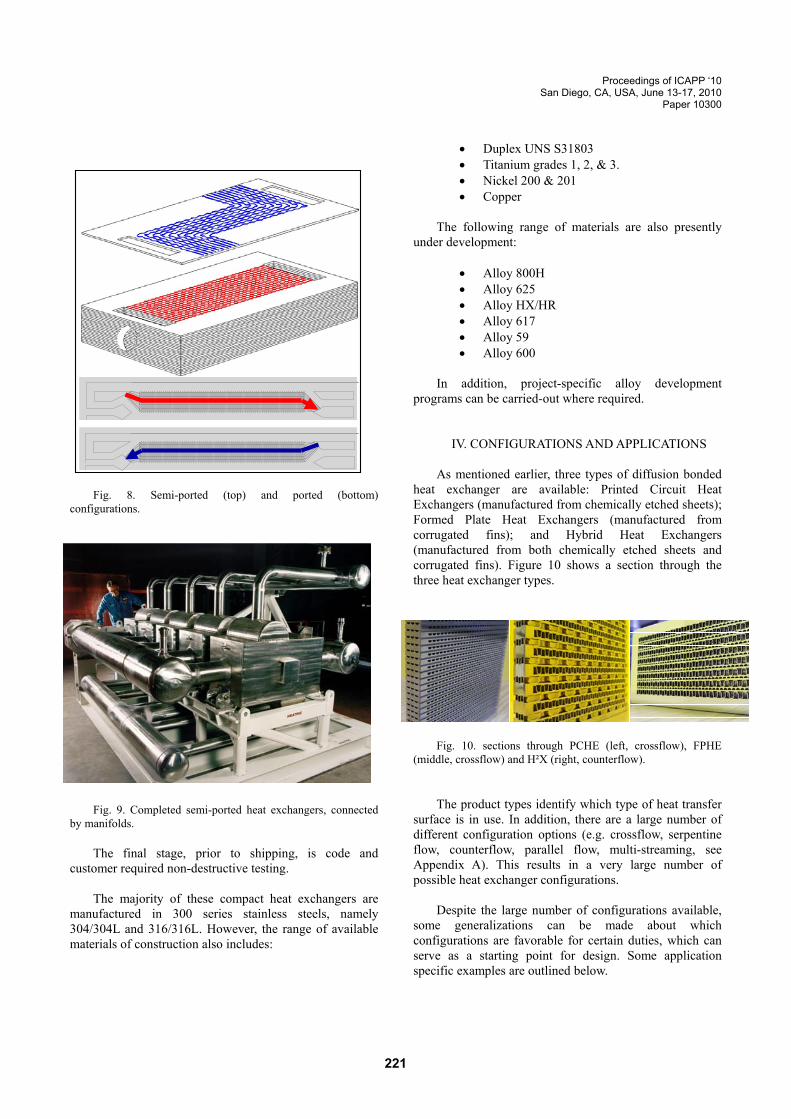
at the chemical etching stage; this produces integral headers. Figure 8 shows typical ported/semi-ported options, with figure 9 showing a completed assembly of semi-ported heat exchangers (i.e. heat exchangers with a mixture of headers and integral ports), which have been connected by manifolds.
0
Proceedings of ICAPP ‘10 San Diego, CA, USA, June 13-17, 2010
Paper 10300
Fig. 8. Semi-ported (top) and ported (bottom)configurations. Fig. 9. Completed semi-ported heat exchangers, connected
by manifolds. The final stage, prior to shipping, is code and
customer required non-destructive testing. The majority of these compact heat exchangers are
manufactured in 300 series stainless steels, namely 304/304L and 316/316L. However, the range of available materials of construction also includes:
22
• Duplex UNS S31803 • Titanium grades 1, 2, & 3. • Nickel 200 & 201 • Copper
The following range of materials are also presently
under development:
• Alloy 800H • Alloy 625 • Alloy HX/HR • Alloy 617 • Alloy 59 • Alloy 600
In addition, project-specific alloy development
programs can be carried-out where required.
IV. CONFIGURATIONS AND APPLICATIONS As mentioned earlier, three types of diffusion bonded
heat exchanger are available: Printed Circuit Heat Exchangers (manufactured from chemically etched sheets); Formed Plate Heat Exchangers (manufactured from corrugated fins); and Hybrid Heat Exchangers (manufactured from both chemically etched sheets and corrugated fins). Figure 10 shows a section through the three heat exchanger types.
Fig. 10. sections through PCHE (left, crossflow), FPHE
(middle, crossflow) and H²X (right, counterflow). The product types identify which type of heat transfer
surface is in use. In addition, there are a large number of different configuration options (e.g. crossflow, serpentine flow, counterflow, parallel flow, multi-streaming, see Appendix A). This results in a very large number of possible heat exchanger configurations.
Despite the large number of configurations available,
some generalizations can be made about which configurations are favorable for certain duties, which can serve as a starting point for design. Some application specific examples are outlined below.
1

Proceedings of ICAPP ‘10 San Diego, CA, USA, June 13-17, 2010
Paper 10300
t
ut
IV.A. Coolers A large number of coolers have been supplied over
the years. Typically, a gas stream is cooled using a closed loop water supply, or water/glycol mixtures. Coolers are usually designed as PCHEs, either in crossflow (see app. A fig. A4), counterflow with crossflow inlet and outlet (see app. A fig. A1), or cross-counterflow (see app. A fig. A5). The configuration selected is a result of optimization, for example to save space and weight, or cost.
Fig. 11. typical PCHE cooler configurations The examples in fig. 11 show coolers where headers
and nozzles are used to distribute flow into the heat exchangers; ported and semi-ported designs (see fig. 8 and fig. 9) are also common.
IV.B. Gas/gas recuperator Another common application is for gas/gas
recuperators, such as may be used in a Brayton cycle. These duties typically require a high thermal effectiveness, for which compact heat exchangers are ideal.
One example of this would be a recuperator for a
helium Brayton cycle. PCHEs, with their compactness and surface enhancement, are a good fit for this application. However, the lower pressure means that FPHEs are also feasible. When the design temperature is high enough to shift the material of construction from 300 series stainless steel to a more expensive, exotic alloy (e.g. 800H or 617), FPHEs may be more attractive as less raw material is required to fold a fin than to etch a channel, reducing the
Gas in
Gas out
Coolantin
Coolantout
Gas in
Gas out
Coolanin
Coolantout
quantity of material required and thus the cost.
222
Fig. 12. typical recuperator configurations. The left hand
arrangement is in counterflow,; the right hand arrangement has crossflow inlets and outlets are superimposed in alternating cold gas layers.
Another example would be a recuperator for a
supercritical CO2 Brayton cycle. These duties also typically require a high thermal effectiveness.
The required design temperature for a CO2
recuperator is generally compatible with 300 series stainless steel, and 316L is usually selected. However, the higher design pressure required (c. 200 bar) means that a PCHE is usually specified, as these are capable of higher design pressures than FPHEs.
IV.C. Sodium/CO2 Intermediate Heat Exchanger Sodium/CO2 Intermediate Heat Exchangers (IHXs)
are an example of a duty where one heat exchanger must satisfy design requirements for two very different fluids.
The sodium side is low pressure (close to
atmospheric), with a very high coefficient of heat transfer (often > 100 000 W/m².°C), with a requirement for larger channels to avoid plugging.
The CO2 side is higher pressure (often > 200 bar),
driving the design towards smaller channels, and a relatively poor coefficient of heat transfer.
For this duty, One would typically design a Hybrid
Heat Exchanger (or H²X), to combine the attributes of PCHEs and FPHEs.
Hot gas in
Hot gas outCold gas in
Cold gas out
Hot gas in
Hot gas out
Cold gas in
Cold gas out
Cold gas in
Cold gas o

Proceedings of ICAPP ‘10 San Diego, CA, USA, June 13-17, 2010
Paper 10300
Fig. 13. Na/sCO2 H²X example. The sodium is on the fin side, where larger channels
are possible. The CO2 is on the etched side, which can be designed for higher pressures and to provide a greater degree of heat transfer enhancement (see fig. 2). Typical configurations are as shown in Fig. 14, permitting free draining of the liquid sodium from the heat exchanger.
Fig. 14. Example Na/sCO2 H²X configurations.
IV.D. Sentinel (or Double Plate) designs Sentinel plates can be integrated into most of these
compact heat exchanger designs, and are useful where safety and/or process requirements dictate that additional precautions be taken to reduce the risk of the two heat exchange fluids from mixing. An example is shown in fig. 15 below:
Fig. 15. Sentinel plate example. If a cross pass leak were to occur, the fluid would leak
into the sentinel plate, preventing the A side and B side fluids from mixing and enabling continuous on-line monitoring.
IV.E. Kettle configurations for naturally circulating flow
Another application for compact heat exchangers is to
replace the tube bundle in a kettle-type shell and tube heat exchanger. This is achieved by removing the headers from a compact heat exchanger, and configuring the unit inside a vessel so that thermosyphon flow can be established.
Fig. 16. Kettle configuration for a compact heat exchanger
in thermosyphon flow. This configuration is possible for PCHE, FPHE, and
H²X block types. Fig. 16 shows a horizontal arrangement; vertical arrangements are also feasible, if required.
CO2 layersSodiumlayers
Na in
Na out
CO2 in
CO2 out
CO2 in
CO2 out
Na in
Na out
CO2 out
CO2 in
Side A Plate
Sentinel Plate
Side B Plate
Coldfeed
Liquidsump
Cold side vapor outlets
Hotfeed
Hotreturn
223

Proceedings of ICAPP ‘10 San Diego, CA, USA, June 13-17, 2010
Paper 10300
IV.F. Multi-streaming One area where compact heat exchangers have been
exploited for a number of years is in multi-streaming. Figs. A7 and A8 in app. A show two example plate configurations for three-stream duties.
Multi-steaming is of benefit where a process can be
optimized through better heat integration. It also has the benefit that the common stream’s pressure drop (see. App. A fig. A7) can be used to promote heat transfer, rather than to pipe the fluid between two separate heat exchanger sections.
The examples given show three-stream heat
exchangers; more streams can be accommodated, but is limited chiefly by the number of piping connections that can be fitted practically on to the heat exchanger.
Fig. 17. Multi-stream example, showing an integrated
recuperator and cooler.
IV. CONCLUSIONS The examples discussed in this paper are not
exhaustive. In fact, the majority of these compact heat exchangers are custom-designed for their particular duty.
With a wide range of surface and material types,
configuration options, and applications, Heatric’s products are Innovative Compact Heat Exchangers, for demanding duties.
Hotgas in
Hot gasout
Cold gasout
Cold gasin
Coolant inCoolant out
224
REFERENCES
1. D. C. SOUTHALL, “Diffusion Bonding in Compact Heat Exchangers,” Proceedings of ICAPP ‘09, Paper 9069, Tokyo, Japan (2009).
2. X. LI, T. Smith, D. Kininmont, and S. J. Dewson,
“Materials for Nuclear Diffusion-Bonded Compact Heat Exchangers,” Proceedings of ICAPP ‘09, Paper 9058, Tokyo, Japan (2009).
3. D. C. SOUTHALL, R. Le Pierres, and S. J. Dewson,
“Design Considerations for Compact Heat Exchangers,” Proceedings of ICAPP ‘08, Paper 8009, Anaheim CA, USA (2008).

Proceedings of ICAPP ‘10 San Diego, CA, USA, June 13-17, 2010
Paper 10300
APPENDIX A.
Fig. A1, counterflow example with cross-flow inlet and outlet.
Fig. A2, counterflow example in a platelet configuration.
Fig. A3, parallel flow example with side-side and end-end
flows.
Fig. A4, crossflow example.
Fig. A5, cross-counterflow example.
Fig. A6, serpentine counterflow example.
225

Proceedings of ICAPP ‘10 San Diego, CA, USA, June 13-17, 2010
Paper 10300
Fig. A7, three stream example, one hot stream with two cold streams in series.
Fig. A8, three stream example, one hot stream with two cold streams in parallel.
Fig.A9, example showing internal flow mixing.
Fluid 2
Fluid 1
Mixture
226
Related Documents