Build a Booster Amp for your Car Stereo 0¡ 48784 THE MAGAZINE FOR THE ELECTRONICS ACTIVIST! Build an Electronic Darkroom Timer Simple to make, it delivers picture - perfect results every time! Innovations '89 The best -of- the-best in consumer electronics Supplying the Electronics Workshop Where to turn when that special something is nowhere to be found Preventive Computer Maintenance Take these simple steps now to prevent big repair bills later Quantum Mechanics, the Universe, and Electronics Learn the true story about what makes electronics work Sub -Audio Frequency Meter Measures low- frequency signals that confound conventional meters 0 48784 11 $2.50 U.S. $2.95 CANADA 3 NEW FactCards IN THIS ISSUE s AmericanRadioHistory.Com

Welcome message from author
This document is posted to help you gain knowledge. Please leave a comment to let me know what you think about it! Share it to your friends and learn new things together.
Transcript
Build a Booster Amp for your Car Stereo 0¡ 48784
THE MAGAZINE FOR THE ELECTRONICS ACTIVIST!
Build an
Electronic Darkroom Timer Simple to make, it delivers picture - perfect results every time!
Innovations '89 The best -of- the -best in consumer electronics
Supplying the Electronics Workshop Where to turn when that special something is nowhere to be found
Preventive Computer Maintenance Take these simple steps now to prevent big repair bills later
Quantum Mechanics, the Universe, and Electronics Learn the true story about what makes electronics work
Sub -Audio Frequency Meter Measures low- frequency signals that confound conventional meters
0 48784
11
$2.50 U.S.
$2.95 CANADA
3 NEW
FactCards IN THIS ISSUE
s
AmericanRadioHistory.Com
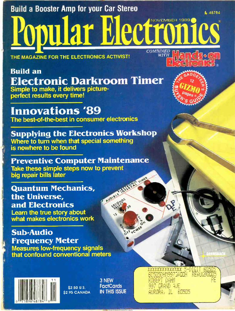
Radio Ihaek Parti PIaeé" WE HAVE WHAT YOU NEED FOR HOLIDAY PROJECTS!
New Battery "Hotline" Service- Hundreds of Types Available We Can Now Supply Virtually Any Currently Manufactured Battery!
In addition to our large in -store stock, Radio Shack can now supply almost any battery. Our expanding selection even includes special communications batteries for walkie- talkies and pagers. Batteries are sent from our warehouse to the Radio Shack near you. And there's never a postage or handling charge.
For Damage -Free IC Handling (1) (2)
(3)
(1) IC In /Out Tool Kit. For 6 to 40 -pin DIPs. #276 -1581 6 95
(2) IC Pin Aligner. #276 -1594 ... 2.99 (3) Conductive Foam. 5 x 5" safety mat for your bench. #276 -2400 1 29
(4)
(4) Static -Draining Wrist Strap. With 24" ground lead and mini alligator clip. #276 -2397 3 29
(5) Soldering Heat Sink. Prevents heat damage. #276 -1567 1 39
RS -232 Connectors, Accessories (1)
(3)
(2)
(1) (2) Solder -Type D -Sub Connectors Type Cat No. 'Each
Male 9 Female 9
276-0537 276 -1538
99 199
Type Cal No Each
Male 25 Female 25
276.1547 276 -1548
1 49 2.49
(3) Metal- Shielded Connector Hoods. 9- Position. #276 -1508 2 19 25- Position. #276 -1510 .. 2.79
(6)
(4) Inline RS -232 Tester. Spot line prob- lems fast. #276 -1401 14.95 (5) NEW! Shielded Stunt Box. Wire in- cluded PC board to suit. #276 -1403, 9.95 (6) NEW! DIP Shunts. #276 -1512 Pkg. of 10/1.29
Meter and Box
1111 (1)
(2)
(1) 0 -15 DC Voltmeter. Mounts in 17 /e" round hole. #270 -1754 7 95
(2) Two -Piece Enclosure. Easy to drill or shorten, if desired. Accepts PC board and 9V battery. 55/e x 21/a x #270 -257 4 99
Mini Audio Amp
1195 High -Gain IC Design
With a built -in speaker, it's the perfect test amp and also well- suited for com- puter voice and music synthesis applica- tions. Has volume control and '/e" input and earphone jacks. #277-1008
"PC" Line Cords (1)
(2) (3)
Top -quality, grounded 6 -foot AC cords for com- puters, printers, business machines. UL listed.
(1) With Straight HP (SEE-Type) Connector. #278 -1257 399
(2) With 90° HP Connector. Ideal for tight spaces. #278 -1260 5 99
(3) Extension. #278 -1259 499
Harness the Sun
(1) (2) V (1) Silicon Solar Cell. Produces about 0.3 amp at 0.55VDC. #276 -124 .. 3.95 (2) Solar Project Kit. Includes mini so- lar panel, motor, propeller, project book- let. #277 -1201 10.95
(1)
Assortments
(2) 3 (1) 20 LEDs. Assortment may include MV -5054, MV -50, RL -209 in red, green, amber, infrared. #276 -1622 1 98 (2) 5 Photocells. CdS photoresistors. Ideal for experiments. Various styles and ratings. #276 -1657 1 98
Power Hookups
1795, Ideal for Nintendo'
Adds extra zip to popular video games! Features autofire switch, two separate "fire" buttons and start /select control. #270 -1704 'Registered trademark of Nintendo
Locking Plugs
With Crimp Pins
Positions Type Cat. No Each
2 Male 274 -151 .99 6 Male 274 -152 1.69
12 Male 274 -153 1.99 2 Female 274 -154 .99 6 Female 274 -155 1.69
12 Female 274 -156 1.99
(1)
Infrared Buys 0r
11 Ill1 Design Your Own (2) // IR Control System
(1) IR Detector Module. Detector, amp. limiter, filter and more! #276 -137, 3.49 (2) SEP8703 -1 IR LED. High power out- put. #276 -143 1 69
Probe -Style Multitester "Pro" Soldering Station
3995
3995 Ideal for Testing On- the -Go
Convenient data -hold button freezes display and lets you remove tester for easy reading. Features autopolar- ity, continuity sounder, low- battery indicator. Measures to 400 volts AC /DC and resistance. 13he x6,/ex 3/e': With batteries and case. #22 -165
A super gift for any builder! Features selectaole 15/25 - watt power, sponge cleaner and fully grounded tip. UL listed AC. #64 -2057 Iron -Clad Replacement Tips. #64 -2089 .... Pkg. of 2/4.99 Tips for Soldering Surface - Mount Devices. #64 -2074 .... Pkg. of 2/4.99
Over 1000 items in stock! Binding Posts, Books, Breadboards, Buzzers, Capacitors, Chokes, Clips, Coax, Connectors, Fuses, Hardware, ICs, Jacks, Knobs, Lamps, Multitesters, PC Boards, Plugs, Rectifiers, Resistors, Switches, Tools, Transformers, Transistors, Wire, Zeners, More!
Prices apply at participating Radio Shack stores and dealers
Breadboard & Jumpers
1995
(1) (2)
495
(1) Deluxe Breadboard. Molded 21/a x 61 /2" board is mounted on a 7 x 4" steel base with rubber feet. 640 plug -in points and three binding posts. #276 -169
(2) NEW! 140 -Piece Jumper Wire Kit. #276 -173
Radie lhaek The Technology Store "
a ItwSIpN IaN[11 o, igPORA-iOr-
CIRCLE 13 ON FREE INFORMATION CARD
AmericanRadioHistory.Com
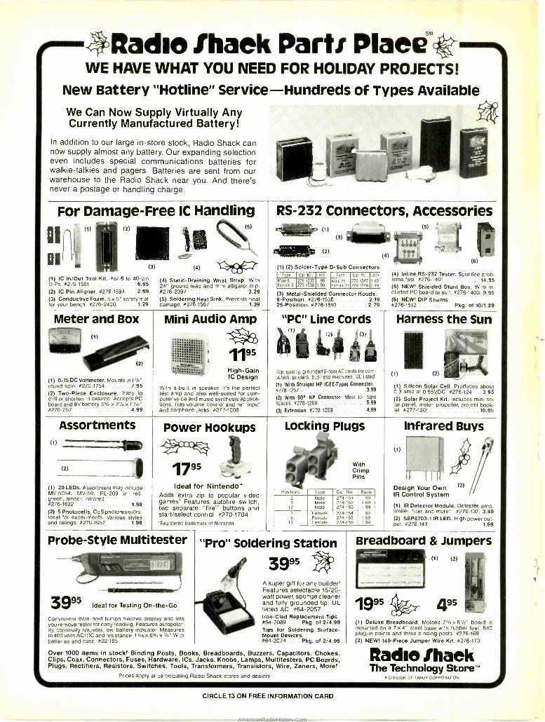
NOVEMBER 1989, VOLUME 6, NO. 11
Popular Electronics
THE MAGAZINE FOR THE ELECTRONICS ACTIVIST!
CONSTRUCTION ARTICLES BUILD AN ELECTRONIC DARKROOM TIMER Douglas E. Pope 33
Let this simple circuit watch the clock for you
SUB -AUDIO FREQUENCY METER Joseph J. Carr 35
Now you can monitor low -frequency signals that confound most other meters
TOUCH -CONTROLLED DIMMER SWITCH Mike Giamportone 39
Get all the convenience of commercial units in a home -brew circuit
BOOSTER AMP FOR YOUR CAR STEREO Gordon Kaye 43
A little extra power can make your car stereo sound like a concert hall
VOICE -OPERATED SWITCH Luther M. Stroud 76
Makes home lighting and appliances respond to your beck and call
FEATURE ARTICLES QUANTUM MECHANICS, THE UNIVERSE, AND ELECTRONICS Joseph J. Carr 61
Explore the world of subatomic particles
PREVENTIVE COMPUTER MAINTENANCE Isaac Szlechter 63
With some tender loving care you can avoid computer repair
INNOVATIONS '89' Byron G. Wels 67
We present the cream of the crop in consumer -electronics products
SUPPLYING THE ELECTRONICS WORKSHOP Stanley Black 70
Where to find that special something that makes your project worthwhile
THE ELECTROLYSIS OF WATER Stanley Czarnik 73
You'll enjoy busting molecules with this inexpensive experiment
THE DIGITAL ELECTRONICS COURSE Robert A. Young 79
Learn about the building blocks that make computers possible
PRODUCT REVIEWS BECKMAN INDUSTRIAL CIRCUITMATE DM27 DIGITAL MULTIMETER 46
Its light, easy -to -use, and a project builder's most valuable instrument
GIZMO 49 Including: Seiko Kitchen Whiz Computer, Grundig Stereo /Digital VCR, Sony Cordless Headphones, and more
COLUMNS Byron G. Wels 23
Jeff Holtzman 82
Charles D. Rakes 84
Joseph J. Carr 86
Marc Ellis 88
Don Jensen 94
Marc Saxon 96
THINK TANK I really don't believe it
COMPUTER BITS Using macros
CIRCUIT CIRCUS Some additions to the workbench, and more
HAM RADIO A look at the Cushcraft R -5 vertical antenna
ANTIQUE RADIO Putting the "Wasp" together again
DX LISTENING TWR provides listening targets for SWLs
SCANNER SCENE A back -to- basics scanner
DEPARTMENTS EDITORIAL
LETTER BOX
ELECTRONICS LIBRARY
NEW PRODUCTS
FACTCARDS
FREE INFORMATION CARD
ADVERTISER'S INDEX
Carl Laron 2
4
6
15
47
65
108
Popular Electronics (ISSN 1042 -170X) Published monthly by Gemsback Publica-
tions, Inc.. 500 -8 Bi- County Boulevard, Farmingdale, NY 11735. Second -Class postage paid at Farmingdale, NY and at additional mailing offices. One -year, twelve
issues, subscription rate U.S. and possessions $21.95, Canada $26.95. all other
countries $29.45. Subscription orders payable in U.S funds only, International Postal
Money Order or check drawn on a U.S. bank. U.S. single copy price $2.50. O 1989 by
Gemsback Publications, Inc. All rights reserved. Hands -on Electronics and Gizmo trademarks are registered in U.S. and Canada by Gernsback Publications, Inc. Popu- lar Electronics trademark is registered in U.S. and Canada by Electronics Technology
Today, Inc. and is licensed to Gemsback Publications. Printed in U.S.A.
Postmaster: Please send address changes to Popular Electronics, Subscription Dept., P.O. Box 338, Mount Morris, It. 61054-9932.
A stamped selt- addressed envelope must accanpany all submitted manuscripts and
or artwork or photographs if their return is desired should they be rejected. We disclaim any responsibility for the loss or damage of manuscripts andior artwork or photographs while in our possession or otherwise.
As a service to readers, Popular Electronics publishes available plans or information
relating to newsworthy products, techniques and scientific and technological develop- ments. Because of possible variances in the quality and condition of materials and workmanship used by readers, Popular Electronics disclaims any responsibility for
the safe and proper functioning of reader -built protects based upon or from plans or information published in this magazine.
1
AmericanRadioHistory.Com
2
Popular Electronics® Larry Steckler
EHF. ('ET Editor -In-(' and Publisher
EDITORIAL DEPARTMENT
Carl Laron .if a too {cirt,c Edam
Robert A. Young Associate Ediu,,
John J. Yacono Associate Editor
Byron G. Wels, K2AVB Associate Editor
Teri Scaduto Assistant Editor
Kathryn Campbell Editorial A.c.,istaat
Robert A. W. Lowndes Editorial Associate
Marc Spiwak Editorial A s.vnimr
Joseph J. Carr, K4IPV Marc Ellis
Jeffrey K. Holtzman Don Jensen
Charles D. Rakes Marc Saxon
Cnnrrihming Fditnrs
PRODUCTION DEPARTMENT
Ruby M. Yee Production Director
Karen S. Tucker Production Ms,s,ss r
Marcella Amoroso Production Ass stant
ART DEPARTMENT
Andre Duzant Art Direar
Russell C. Truelson Tec hrdcal Illustrator
lnjae Lee Assistant Illustrator
Jacqueline P. Cheeseboro Ctrr War ion Director
Michele Torrillo P Bookstore
BUSINESS AND EDITORIAL OFFICES
Gernsback Publications, Inc. 500 -B Bi- County Blvd.
Farmingdale, NY 11735 1- 516- 293 -3000
Fax: 1-516-293-3115 President: Larry Steckler
Vice President: Cathy Steckler
Advertising Sales Offices listed on page 108
Cover photography by Diversified Photo Services
Composition by Mates Graphics
and Magtype
*' The Audit Bureau
of Circulation
The publisher has no knowledge of any proprietary rights which will be violated by the making or using of any items disclosed in this issue.
Editorial
PASS IT ALONG In an age when the public perceives an erosion in America's "technological superiority," it becomes ever more important to make certain that succeeding generations carry on this country's tradition of invention and ingenuity.
Many corporations'are doing their bit to impart the spark of knowledge to young people. Companies like Westinghouse, Mallory (through their Duracell subsidiary), and others sponsor science and design competitions for youngsters. The best entries earn scholarships, recognition, and prestige. But everyone who competes is a winner; their prize is a better understanding of the creative process, and a head start toward their future.
We at Popular Electronics are also trying to do our part. Each issue features projects, how -to articles, and much more designed specifically for youngsters and beginning hobbyists. From time -to -time we offer articles that allow you to explore for yourself some of the basic principals of science and electronics. This month for instance, "Electrolysis of Water" (see page 73) allows you to recreate one of science's most famous experiments.
But, parents, we can't do our part if you don't help. When you are done with an issue, pass it along to your youngsters. Point out some of the things that you think might be of interest. Or, better yet, volunteer to help your child build one of our projects or perform one of the experiments. (And kids, if this is your issue, pass it along to your parents; they work hard and deserve some fun, too.)
And speaking of passing things along, you may have noticed a change on our Masthead. Julian Martin has left Popular Electronics to accept another assignment within our company. Julian has been with this magazine, and its predecessors (Special Projects and Hands -on Electronics), since its inception. He has seen it through its tough times and its good times, and has left an indelible mark on everything we do here. Now the job of making this magazine the best it can be for its readers has been passed to me. I have some big shoes to fill, and some high standards to live up to.
Carl Laron Managing Editor
AmericanRadioHistory.Com
MASTEP HANDBOOK
OF
PRACTICAL ELECTRONIC
CIRCUITS
O Kendall Webster
Sessions
2980 $28.95
7912P $14.95
SELECT 5 BOOKS for only $495
Resit IftCtaOfliis
Course
2613 424.95 Counts as 2
e ooaau ' FIBEROPTKS ELECTRONIC AHD LASER
CIRCUITS
1038 $60.00 Counts as 3
2981P $16.95
1_ ---- 11{F.91Ix£Y' -
,GAWtNYQr t1IXTH[,I'
I. k, 1,i
w,t W 0.xír., n"
cMNI-
(values to $120.70)
and get a FREE Gift!
I BE ILLUSTRATED
HOME ELECTRONICS FIX-IT BOOK
2883P $16.95
Electronics projects ... ideas ... the latest technology all at up to 50% off publishers' prices!
Membership Benefits Big Savings. In addition to this introductory
offer, you keep saving substantially with members' prices of up to 50% off the
publishers' prices. Bonus Books. Starting immediately, you will be eligible for
our Bonus Book Plan, with savings of up to 80% off publishers' prices. Club
News Bulletins. 14 times per year you will receive the Book Club News, describ-
ing all the current selections- mains, alternates, extras -plus bonus offers and
special sales, with scores of titles to choose from. Automatic Order. If you want
the Main Selection, do nothing and it will be sent to you automatically. If you prefer
another selection, or no book at all, simply indicate your choice on the reply form
provided. As a member, you agree to purchase at least 3 books within the next
12 months and may resign at any time thereafter. Ironclad No -Risk Guaran-
tee. If not satisfied with your books, return them within 10 days without obliga-
tion! Exceptional Quality. All books are quality publish, s' editions especially
selected by our Editorial Board.
2900P $24.95 1604P 517.95 ? 1989 ELECTRONICS BOOK CLUB . Blue Ridge Summit, PA 17294 -0810
All books are hardcover unless number is followed by a "P" for paperback (Publisher's Prices shown). Counts as 2
ELECTRONIC
1625P $18.95
62 HOME RECITE CONTPOI. AUTiIA110N PPM '
"l' ULI('
PLAs FRS
3107 926.95 Counts as 2
Now re Taw
Eltlris$e
2735P $14.95 2925 516.95
The Master Handboa of IC c rcurts
2996P $12.95 3185 034.95 Counts as 2
FREE when you join! 15 Easy Electronic Projects From Delton T. Horn Projects you can build -some unique, some old favorites -from the author's vast treasury of electronics know -how.
DeltonT.Hom's All -Time Favorite lectronic Projects
ELECTßUfy03 ß00K CHUB 7 Blue Ridge Summit, PA 17294 -0810
Please accept my membership in the Electronics Book Club' and send the 5 volumes listed
below, plus my FREE copy of Delton T. Horn's All -Time Favorite Electronic Projects (3105P),
biting me $4.95 plus shipping and handling charges. If not satisfied, I may return the books
within ten days without obligation and have my membership cancelled. I agree to purchase
at least 3 books at regular Club prices (plus shipping /handling) during the next 12 months and
may resign any time thereafter.
I I I
1 1 1 1
Name
Address
City -
State Zip Phone
Signature Valid for new members only. Foreign applicants will receive special ordering Instructions. Ganda must remet in
U.S. currency. This order subject to acceptance by the Electronics Book Club' PE1189
METERS
SCOPES NOw' ill l tt
Irrt tol'IPt1tsi
2826P $15.95
0°earet aro
2875 $17.95
IYIiOCISti
Il sNtl.0 ItF.fEA'Til IS'
xtsti81V. t1111t4 i\I, stt11.11if V14(10
2970P $15.95
2947 $21.95
1599P $17.95
READINC SCHEMATIG>
1536P 09.95
Troubleshooting and Repairing
VCRs swab McComb
WI AL. ,oW'
2960 $27.95 Counts as 2
2707 $26.95 Counts as 2
- alllJ> 1o1 N oN-h
IBM vtnnl n SAVE A 1311NDI,F.
tl,utJ
4+,
I al Enhancement ProleAta
3234 $24.95
2831P 014.95 3195 528.95 Counts as 2
3133 S15.95 2809 $27.95 Counts as 2 3
AmericanRadioHistory.Com
4
Letters PLENTIFUL PARTS
I found your article, "The Parts Connection," (Popular Electronics, July 1989) very infor- mative. I would like to add one more name to your list of parts distributors. DC Electron- ics (P.O. Box 3203, Scottsdale, AZ, 85271- 3203; 800 -423 -0070) carries a large stock of transistors, chips, voltage regulators, etc. - just about anything you'd need to build the projects that appear in Popular Electron- ics. They have a $15.00 minimum, but that is waived if you prepay your order. I have found them to be very helpful and courteous.
L.F. Corona, NY
I found the article, "The Parts Connection," in the July issue to be an excellent guide to assist someone in understanding the vari- ous types of common electronic compo- nents. I'm a faculty member in an Electrical Engineering Technology program and I plan to distribute the article to some undergradu- ate classes (if I receive your permission, of course).
I'd like to point out the error in the power formula on page 59 of the article. Obviously, it should read:
Power (in watts) = V2 /R. W.D.S.
Old Dominion University Norfolk, VA
ANTI -GRAVITY UPDATE I have two comments about the "Anti- Gravity Generator" that appeared in the May 1989 issue of Popular Electronics. I would sug- gest adding a reverse -biased diode (1N4001, for example) in parallel with L1, to prevent high (and damaging) voltages from developing across Q1 and Q2 if the current in L1 is abruptly turned off. Also, the inverting and non -inverting inputs of the op amps were incorrectly labeled in the sche- matic! The 741 pinouts were correct, (which finally tipped me off), but for someone using a dual op amp instead of the two 741's, it would surely cause major confusion.
P.C. Dartmouth, Nova Scotia
Canada
HIGHER IS BETTER I would like to call to your attention an error I found in "The Square Tesla Coil," which
appeared in the August 1989 issue of Popu- lar Electronics. The "Q" of a coil is a rating of its efficiency, and (yes) it is found by divid- ing the reactance by its internal resistance (the actual resistance of the wire itself): XL/R.
However, the "Q" is better when it is higher, not lower. The expression XL /R shows that when the resistance goes up, the efficiency goes down, and as the resistance goes down, the efficiency goes up. The re- sistance produces heat, which (of course) expends energy; therefore the efficiency drops instead of rising.
I felt that this information would be critical for all your readers who intend to build the fascinating static -field generator.
C.H.A. Hartland, VT
A CHANGE OF HEART As an "old- timer" (licensed 22 years), and dedicated CW operator, I have until recently adamantly opposed the "code- free" license. Within the last few years, however, I have come to realize that such a step may be necessary if the hobby is to attract enough new recruits to survive.
However, I think that any code -free license should be predicated on the following: 1) Strict FCC examination supervision. The idea of volunteer examiners invites tempta- tion and abuse. 2) Promotion of code operation and recogni- tion of CW- qualified operators via some sort of "honorary" license grade, certificate -of- merit, etc.
The usual good reasons for maintaining CW as a license requirement are: (1) simple and inexpensive transmitters, (2) narrow bandwidth, (3) very low transmission -error rate, and (4) international recognition.
An additional reason that I have noted is use of this mode by persons who do not have a good command of spoken English, have pronounced accents, have speech im- pediments, or who are too shy to communi- cate well verbally. Such individuals can still enjoy and contribute to hamming through the use of code.
Thanks for listening, and keep up the good work.
R.W.
Waukesha, WI
DOESN'T MAKE SENSE
I must respectfully take exception to your editorial in the September 1989 issue of Popular Electronics.
Given recent events, one might think that for a couple of hundred years this nation has labored under a gross delusion that the best test of what the public wants is what it is willing to spend its money on. Now comes a competing theory. The new idea is that since somebody would like to make and sell High Definition Television (HDTV) sets, the government should force the public to pay
the start -up cost and should disregard the question of what the buying public would spend for, given a free choice.
For the past couple of years, the Ameri- can consumer -electronics industry has been saying that HDTV is coming and that HDTV sets could be America's last chance to hold on to its electronics industry. The problem, they say, is that American manufacturers would have to invest a lot of money to get started. My response is, "If you think it's a good bet, invest your own company's money and get ready to reap your reward. But if you're not confident, don't expect me to get too interested."
The electronics industry has not had much success so far in getting the government interested in either expeditiously setting HDTV standards or laying out a direct sub- sidy for research and development costs. It also apparently was not too skilled at lip reading during the 1988 elections. In May 1989, Jerry Pearlman, Chairman and CEO of Zenith Electronics Corp., a company which is a big would -be player in the HDTV field, suggested that the U.S. should support HDTV R &D by laying a new five -dollar tax on each TV set sold.
I may be looking at too small a slice of the population, but I have to ask: When was the last time someone told you that he was terribly dissatisfied with NTSC color televi- sion and just had to have a higher definition picture? An old- fashioned economist might be inclined to suggest that if a whole lot of people were clamoring to buy HDTV sets, there wouldn't be any need to ask the gov- ernment for a handout to make the things. Does the industry's demand for an HDTV subsidy suggest that, just maybe, there's not much of a market for them?
The history of TV is littered with the car- casses of neat ideas that didn't make it in the market: Stratovision, the CBS color sys- tem, Electronic Video Recording, Beta cas- settes, Direct Broadcast Satellite, and video disks, for example. While at least one of those enjoyed some success, those neat ideas didn't meet a demand of the market, and therefore failed.
It doesn't take a lot of market research to find telecommunications equipment that people do want in mass quantities: fax ma- chines, two -way radios, cellular phones. And how do we know? Every day people reach into their pockets and willingly hand over hard -earned money to buy them. To make those goods and services available, the in- dustry has taken its own risks and losses - and collected its own well- earned rewards.
D.C.B. Washington, DC
HAVES AND NEEDS
I have a Zenith TV model SE2028W and would like to buy the service manual for it. I have written to two of their addresses and so far have been unsuccessful. I also have a Zenith 1929 radio, model 52, that I've had
AmericanRadioHistory.Com
no luck getting information on, despite writ- ing and calling the company. Can you help?
Carl F. McCormick 3151 Grand Lake Drive
Fremont, CA 94555
I own a Grundig model 101U AM /FM re-
ceiver and have encountered difficulty locat- ing any service literature. Any information on the unit would be helpful.
Joe LaFrance 60 Sayles St.
Southbridge, MA 01550
My boss recently gave me an Allied AX -190
shortwave receiver. Unfortunately, he had
lost the user manual and a check with Radio
Shack proved useless. I hope that one of
my fellow Popular Electronics readers can
help me with this problem. I would be willing
to pay for copying the manual. John Daniels
Rt. 1, Box 162A McDonald, TN 37353
MYSTERY STATION
Congratulations on the reborn Popular Elec- tronics! I used to read the old Popular Elec- tronics back in the late 1950's and early 1960's, and feel that the new magazine is
even better. I especially appreciate your bal-
ance of material, which ranges from begin- ner's projects to the more advanced articles on theory, math, and computer programs for
custom -designed projects. The breadboard "Q- Multiplier" (May 1989)
so intrigued me that I ordered the June 1988
issue so that I could build the "Simplest Ham
Receiver" and check out how the combina- tion worked. Wonderful! A great bonus was
the explanation of how a direct -conversion receiver works -something I was unaware
of until now. The main reason for writing you is that
when I use a 3579.545 -kHz (color- burst) crys-
tal with the receiver I get a Morse -cede prac- tice transmission at 8 PM (PDT) most eve- nings here in San Francisco from a station identified as W6QIE. I would like more infor-
mation on who is so kindly providing this serv-
ice for those of us on the West Coast who cannot receive W1AW's code -practice trans- mission. Can anyone help me out?
One short note before I end: Radio Shack now carries a 335 -pF variable capacitor that could be used in projects requiring the im-
possible -to -get 365 -pF variable. It is rather fragile, and great care is needed when sol- dering components to it, but it seems to do
the job. Again, thank you for providing a truly won-
derful magazine that is a refreshing depar- ture from other periodicals that concentrate on computer -related electronics.
G.R.
San Francisco, CA
If any of our readers know anything about that station, write in and tell us about it; we'll pass the information along. And thanks for the capacitor tip!- Editor
.4
CABLE -TV
BONANZA! ITEM UNIT MORE
HAMLIN MCC .100036 CORDED REMOTE CUNVER I E P -Cis , 2900 1800
PANASONIC WIRELESS CONVERTER lour nest buy, 9800 7900
STAR GATE 2000 88 00 69 00
' JERROLD 400 COMBO 16900 11900
JERROLD 400 HAND REMOTE CONTROL 2900 18 00
' JERROLD 450 COMBO 199 00 139 00
-JERROLD 450 HAND REMOTE CONTROL 29 (10 1800
JERROLD SB-ADD -ON 9900 6300
' JERROLD SB- ADD -ON WITH TRIMODE 10900 7500
'M -35 B COMBO UNIT (Ch 3 output onlyi 99170 7000
'M -35 B COMBO UNIT WITH VARISYNC 109 00 500 ' MINICODE W-121 980(1 6200
' MINICODE IN121 WITH VARISYNC 10900 61, OU
' MINICODE VARISYNC WITH AUTO ON-OF F 14500 105 00
ECONOCODE IminicOde suostiema 69 00 47 00
ECONOCODE WITH VARISYNC '900 4600
'MLD-(200- 31Ch 3 oolool, 9900 6200
'MLD- 1200 -2 ICh 201npu11 9900 61' UL
'ZENITH SSAVI CABLE READY 17500 72 + +50n
INTERFERENCE FILTERS Cl, I 3 only. .4 UU 14 00
'EAGLE PD-3 DESCRAMBL ER I Ch i nu4,d ,nI( 1900 ti, 00
'SCIENTIFIC ATLANTA ADD ON REPLACEMENT DEOCRAMHLER ' 1900 8500
Quantity Item Output
Channel Price Each
TOTAL PRICE
California Penal Code #593 -0 forbids us
from shipping any cable descrambling unit to anyone residing in the state of California.
Prices subject to change without notice.
-. -,.- -.-
SUBTOTAL Shipping Add $3.00 per unit
COD & Credit Cards - Add 5%
TOTAL
Name
Address City
State Zip Phone Number (
Cashier's Check Money Order COD Visa Mastercard
Acct # Exp. Date
Signature
FOR OUR RECORDS:
DECLARATION OF AUTHORIZED USE - I, the undersigned. do hereby declare under penalty of penury
that all products purchased. now and in the future, will only be used on cable TV systems with proper
authorization from local officials or cable company officials in accordance with all applicable federal and
state laws. FEDERAL AND VARIOUS STATE LAWS PROVIDE FOR SUBSTANTIAL CRIMINAL AND CIVIL
PENALTIES FOR UNAUTHORIZED USE.
Dated' Signed
Pacific Cable Company, Inc. 73251/2 RESEDA BLVD., DEPT. # P -i i RESEDA, CA 91335
(818) 716 -5914 No Collect Calls (818) 716 -5140
IMPORTANT: WHEN CALLING FOR INFORMATION Please have the make and model # of the equipment used in your area. Thank You
5
AmericanRadioHistory.Com
6
Electronics Library To obtain additional information on the books and publications covered in this section from the publisher, please circle the item's code num- ber on the Free Information Card
The more theoretical concepts are ex- plained right at the start, as are many working practices. Topics such as Boolean algebra and Karnaugh mapping are ex- plained, demonstrated, and used exten- sively. The book wraps up with a discus- sion of how microprocessor techniques are applied to digital logic.
Digital Logic Gates and Flip- Flops: What They Do and How To Use Them (Or- der No. PCP 107) is available for $12.00 (including shipping and handling) from Electronics Technology Today, P.O. Box 240, Massapequa, NY 11762.
CIRCLE 97 ON FREE INFORMATION CARD
ELECTRONIC TEST AND MEASURING
EQUIPMENT
from C.G. Instruments Corp.
More than 50 new products -including a wide array of hand -held digital and analog multimeters with bar -graph indicators -are featured in the SOAR test -instrument cata- log. The 44 -page book also describes digi- tal clamp -on meters, bench DMM's, fre- quency counters, insulation and earth /insu- lation resistance meters, various sizes of digital thermometers, adapters, accesso- ries, and cases. Product descriptions in- clude photos, specifications, and measure- ment ranges -the specific product informa- tion needed for educations, research and development, manufacturing, field service, and maintenance in the electronic industry.
The Electronic Test and Measuring Equipment Catalog is free upon request from C. G. Instruments Corp., 434 Windsor Park Drive, Dayton, OH 45459.
CIRCLE 85 ON FREE INFORMATION CARD
DIGITAL LOGIC GATES AND FLIP-FLOPS: What They Do and How to Use Them
by Ian R. Sinclair
This book provides hobbyists, students, and technicians with an in -depth look at gates and flip -flops -the building blocks of digital electronics. Only a basic knowledge of electronics is needed for clear under- standing of the concepts presented, which represent a firm foundation in digital elec- tronics. Rather than presenting circuits to build, the book presents the knowledge needed to understand important principles and put them to use. By learning how to carry out logic actions with gates and flip - flops, readers also learn the basics of de- signing and troubleshooting digital circuits.
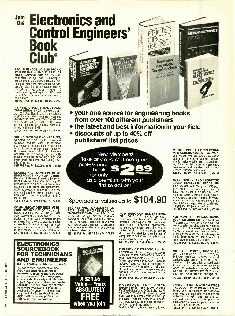
TRANSFORMERS AND MOTORS:
A Single- Source Reference for Electricians
by George P. Shultz
Originally written for the National Joint Apprenticeship and Training Committee (NJATC) for use in training apprentice and journeymen electricians, this book is available for the first time to the general public. The material, which is written clearly and with a minimum of mathemat- ics, ties electromagnetic theory to practi- cal applications. Every chapter ends with self -test questions, with answers.
The book is divided into separate sec- tions on transformers and motors. Each
' Transformers and Motors
section opens with a discussion of funda- mental concepts and provides the detailed information needed for installing, maintain- ing, troubleshooting, repairing, and replac- ing transformers or motors. The trans- former section also covers connections and distribution systems; the motor section also includes chapters on fractional- horse- power and polyphase motors.
Transformers and Motors: A Single - Source Reference for Electricians (No. 22636 -7) is available for $24.95 from How- ard W. Sams & Company, 4300 West 62nd St., Indianapolis, IN 46268; Tel. 800- 428 -SAMS.
CIRCLE 95 ON FREE INFORMATION CARD
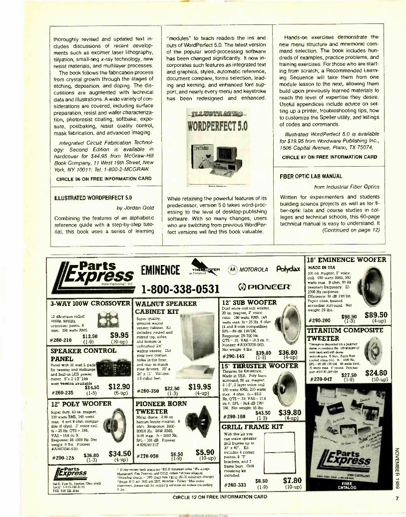
SOUND TECHNIQUES FOR VIDEO & TV
Second Edition
by Glyn Alkin
The ever -growing popularity of camcorders has created a whole new group of "movie producers" -many of whom quickly dis- cover that putting sound and pictures to- gether isn't as easy as it looks. Those en- thusiastic amateurs will find a wealth of practical information in this second edition of a book used for many years as an in- struction manual in sound operations by television stations around the world.
The completely updated book provides detailed descriptions of the techniques used to produce effective sound in asso- ciation with video. Methods for handling each type of production situation are pre- sented, and the format -with a complete topic on each page -makes the book easy
to use as a quick reference guide. Audio theory is examined in a simple, non - mathematical fashion. The underlying prin- ciples of audio /video production are ex- plained throughout the book, and pertinent technical information about basic equip- ment is included.
Sound Techniques for Video & TV: Sec- ond Edition is available for $16.50 from Focal Press, Division of Butterworths, 80 Montvale Avenue, Stoneham, MA 02180.
CIRCLE 86 ON FREE INFORMATION CARD
INTEGRATED CIRCUIT FABRICATION
TECHNOLOGY: Second Edition
by David J. Elliott
Designed to show engineers how to use promising technological innovations to achieve the highest performance stan- dards in each phase of integrated- circuit fabrication, this book explores ways to im- prove IC process resolution, solve adhe- sion problems, achieve better images, and speed up production. Each production step is examined both as a separate entity and as it affects the whole process. This
AmericanRadioHistory.Com
thoroughly revised and updated text in- "modules" to teach readers the ins and Hands -on exercises demonstrate the
eludes discussions of recent develop- outs of WordPerfect 5.0. The latest version new menu structure and mnemonic com-
ments such as excimer laser lithography, of the popular word -processing software mand selection. The book includes hun-
silyation, small -ring x -ray technology, new has been changed significantly. It now in- dreds of examples, practice problems, and
resist materials, and multilayer processes. corporates such features as integrated text training exercises. For those who are start -
The book follows the fabrication process and graphics, styles, automatic reference, ing from scratch, a Recommended Learn -
from crystal growth through the stages of document compare, forms selection, lead- ing Sequence will take them from one
etching, deposition, and doping. The dis- ing and kerning, and enhanced font sup- module lesson to the next, allowing them
cussions are augmented with technical port; and nearly every menu and keystroke build upon previously learned materials to
data and illustrations. A wide variety of con-
siderations are covered, including surface preparation, resist and wafer characteriza-
has been redesigned and enhanced. reach the level of expertise they desire.
Useful appendices include advice on set -
ting up a printer, troubleshooting tips, how
tion, photoresist coating, softbake, expo- to customize the Speller utility, and listings
sure, postbaking, resist quality control,
mask fabrication, and advanced imaging.
Integrated Circuit Fabrication Technol-
ogy: Second Edition is available in
hardcover for $44.95 from McGraw -Hill
WORDPERFECT n
5.0 of codes and commands.
Illustrated WordPerfect 5.0 is available for $19.95 from Wordware Publishing Inc.,
1506 Capital Avenue, Plano, TX 75074.
CIRCLE 87 ON FREE INFORMATION CARD
. '
A' Book Company, 11 West 19th Street, New \ York, NY 10011; Tel. 1- 800- 2- MCGRAW.
CIRCLE 96 ON FREE INFORMATION CARD
'
FIBER OPTIC LAB MANUAL
from Industrial Fiber Optics W-^ -
ILLUSTRATED WORDPERFECT 5.0 While retaining the powerful features of its Written for experimenters and students
by Jordan Gold predecessor, version 5.0 takes word -proc- essing to the level of desktop -publishing
building science projects as well as for fi-
ber -optic labs and course studies in col -
Combining the features of an alphabetic software. With so many changes, users leges and technical schools, this 60 -page
reference guide with a step -by -step tuto- who are switching from previous WordPer- technical manual is easy to understand. It
rial, this book uses a series of learning feet versions will find this book valuable. (Continued on page 12)
Parts EMINENCE TNF t
R MOTOROLA Pelydax
EXPrPqqc PION EC-F2 IOVEUt
3 -WAY 100W CROSSOVER
12 dB/octave rolloff. 800Hz, 5000Hz crossover points. 8
ohm. 100 watts RMS.
$12.50 $9.95 (1 -9) (10 -up) #260 -210
SPEAKER CONTROL PANEL Panel with 50 watt L -pads for tweeter and midrange and built -in LED power meter. 5 "x 2 1/2" 100 watt version available
$14.50 $12.90 #260 -235 (1 -5) (6 -up)
tie
WALNUT SPEAKER CABINET KITS: Super quality, genuine walnut veneer cabinet. Kit
includes: routed and mitred top, sides, and bottom in unfinished 3/4" walnut veneer. Cut your own custom holes in the front and rear to match your drivers. 15" x
24" x 11 ". Volume: 1.9 cubic feet.
#260 -350 $22.50 $19.95 (1 -3) (4 -up)
12" SUB WOOFER Dual voice coil sub woofer. 30 oz. magnet, 2" voice coils. 100 watts RMS, 145
watts max. fs = 25 Hz. 6 ohm (4 and 8 ohm compatible). SPL =89 dB 1W /1M. - Response: 25 -700 Hz. QTS =.31, VAS= 10.3 cu. ft..
Pioneer #A30GU30 -55D. Net weight: 6 lbs.
$36 80 #290 -145
18" EMINENCE WOOFER MADE IN USA
100 oz. magnet, 3" voice coil. 250 watts RMS, 350 watts max. 8 ohm, 30 Hz
resonant frequency. 22-
2700 Hz response. Efficiency 95 dB 1W /1M. Paper cone, treated accordian surround. Net weight: 29 lbs.
#290 -200 $98.90 $89.50
(1 -3) (4 -up)
12" POLY WOOFER Super duty, 40 oz. magnet. 100 watts RMS, 145 watts max. 4 and 8 ohm compat- ible (6 ohm). 2" voice coil. fs= 25 Hz. QTS = .166,
VAS= 10.8 cu ft.
Response: 25 -1500 Hz. Net weight: 9 lbs. Pioneer #A30GU40 -51D
#290 -125 $36.80 (1 -3)
$34.50 (4 -up)
PIONEER HORN TWEETER My:ar dome. 2.93 oz.
barium ferrite magnet. 8
ohm. Response: 1800-
200'30 Hz. 35W RMS,
50W max. fs = 2000 Hz,
SPL = 106 dB. Pioneer #AHE60 -51F
#270 -050 /1 -9) $5 90)
Ezprléss 340 E. First St.. Dayton Oho 45404 Local: 1 -513- 222 -0173 FAX: 513 -222 -4644
15 day money back guararmee'915.00 mnnnun order ' We accept
Mastercard, Vita Discover, and C.OD. enders 14 hour shipping
-Shipping charge = UPS chart rate c$1.01) ($3.00 minimum charge) 'Hours: 8:30 am- 6:00 pm EST, Monday - Friday 'Mail order customers, please call for shipping estimate on orders exceeding 5 lbs.
15" THRUSTER WOOFER Thruster by Eminence Made ut USA. Poly foam surround, 56 oz. magnet. 2 -1/2 ", 2 layer voice coil. 150 watts RMS, 210 watts max. 4 ohm. fs = 23.5
Hz, QTS =.33, VAS= 17.9
cu ft. SPL =94.8 dB 1W/ 1M. Net weight: 15 lbs.
#290 -180 $43.50 (1 -3)
TITANIUM COMPOSITE TWEETER
Titanium n deposited on a polymer dare to combine the advantages of both hard and soft dome techndogiea 8 ohm. Ferro fluid cooled voice cod. fs = 1300 Hz,
SPL = 90 dB 1 W /1M. 50 watts RMS,
70 watts max. 4" round Polydax part #DTW 100T 125.
#270 -047 $27.50
(1 -9) $24.80
(10 -up)
$39.80
GRILL FRAME KIT With this kit you can make speaker grill frames up to 30 "x40 ". Kit
includes 4 corner pieces, 2 'T' brackets, and 7
frame bars. Grill mounting kit included.
#260 -333
(4 -up)
$8.50 $7.80 (1 -9) (10 -up)
CIRCLE 12 ON FREE INFORMATION CARD 7
AmericanRadioHistory.Com
8
Join the Electronics and
Control Engineers'
Club® TROUBLESHOOTING ELECTRONIC EQUIPMENT WITHOUT SERVICE DATA, Second Edition. By R.G. Middleton. 320 pp., illus. This indispen- sable new edition features all the informa- tion that made the first edition so suc- cessful, plus the latest developments in digital testing, phase checks, IC trouleshooting, and repair of VCRs, ste- reos, TVs, tape recorders, and much, much more. 585092 -3 Pub. Pr., $30.00 Club Pr., $22.50
PRINTED CIRCUITS HANDBOOK, Third Edition. By C. F. Coombs, Jr. 960 pp., 556 illus. Here in one handy volume is all the information you need to design, manufacture, test, and repair printed wir- ing boards and assemblies. This new edition features ten all -new chapters, including three on SMT. 126/097 Pub. Pr., $63.50 Club Pr., $45.50
SOUND SYSTEM ENGINEERING, SeCOnd Edition. By D. Davis and C. Davis. 665 pp., illus. The definitive source for all professionals responsible for audio system design, covering every - thing from concert halls to virtually every oscillator in use today. Packed with proven strategies for solving design and engineering problems and cutting your clients' costs. 584657 -8 Pub. Pr., $39.95 Club Pr., $31.50
MCGRAW -HILL ENCYCLOPEDIA OF ELECTRONICS AND COMPUTERS, Second Edition. S. Parker, Editor -in- Chief. 1,047 pp. , 1,250illus. Featuring 160 new and revised articles, this new edition treats the entire spectrum of applications, devices, systems, and theory in areas ranging from the flow of electricity to hardware, software, robotics, and IC fabrication. 454/99X Pub. Pr., $75.00 Club Pr., $49.95
COMMUNICATIONS RECEIVERS: Principles and Design. By Ulrich L. Rohde and T.T.N. Bucher. 608 pp., 402 illus. Everything you need to know if you design or work with communications receivers, from theory to practical design approaches. Coverage includes all types of receivers shortwave, broadcast, radar, military, marine, aeronautical, and more. 535/701 Pub. Pr., $62.50 Club Pr., $44.50
your one source for engineering books from over 100 different publishers the latest and best information in your field discounts of up to 40% off publishers' list prices
New Members! Take any one of these great
professional books 6289
for only as a premium with your
first selection!
Spectacular values up to $104.90 ENGINEERING FUNDAMENTALS FOR THE PROFESSIONAL ENGINEERS' EXAM, Third Ed. By L. M. Polentz. 432 pp., 170 illus. Features worked -out solutions and full explana- tions for all sample problems so you can learn how to solve them. It's a dependable way to prepare for the exam or a perfect on- the -job reference. 503/931 Pub. Pr., $39.50 Club Pr., $27.95
ELECTRONICS SOURCEBOOK FOR TECHNICIANS AND ENGINEERS 592 pp., 800 illus., softbound 335/591 This condensed, paperback version of the Handbook for Electronics Engineering Technicians is the perfect on- the -job reference for all electronics professionals. From fully worked -out ex- amples, explanations, tables, and graphs ... through up-to -date coverage of active filters, microwaves, and fiber optics... to using the full spectrum of technical equipment, the Sourcebook is the single most convenient professional electronics reference available.
A $24.95 Value -Yours ABSOLUTELY
FREE . -..
AUTOMATIC CONTROL SYSTEMS, Fifth Ed. By B. C. Kuo. 736 pp., illus. Provides an overview of automatic control systems, including in -depth coverage of classical control techniques, optimal con- trol theory, and analog and digital control system design. This up -dated edition discusses the latest ideas on the use of computers to design control systems and as components of such systems. 583706 -4 Pub. Pr., $51.00 Club Pr., $36.95
ELECTRONIC DATABOOK, Fourth Edition. By R. F. Graf. 550 pp., hundreds of tables, charts, nomograms, and for- mulas. Get immediate access to the facts, figures, and formulas you need. Coverage includes frequency data, all segments of communications, mathematical data, physical data, passive components, and displays, sensors, memories, and micro- processors. 584940 -2 Pub. Pr., $34.95 Club Pr., $24.50
HANDBOOK FOR SOUND ENGINEERS: The New Audio Cyclopedia., ditedbyG. Ballou. 1,247 pp., over 1,200 illus. This giant handbook gives you truly comprehensive coverage of sound - and the methods of produc- ing, reproducing, controlling, changing, reinforcing, and measuring it. 583913 -X Pub. Pr., $79.95 Club Pr., $55.95
MOBILE CELLULAR TELECOM- MUNICATIONS SYSTEMS. By W.C.Y. Lee. 442 pp., 215 illus. A to Z coverage of state -of- the -art cellular systems, from de- sign to implementation and troubleshoot- ing. Clearly explains spectrum efficiency, propagation models and prediction, inter- ference treatment, and more. 370/303 Pub. Pr., $59.50 Club Pr., $44.50
TRANFORMER AND INDUCTOR DESIGN HANDBOOK, Second Edi- tion. By Col. W.T. McLyman. 440 pp., illus. All the information you need to design today's lighter, smaller transform- ers and inductors, without relying on out- moded approximation methods. In ready - reference tabular format, this new edition covers the latest equations in transformer and gapped design applications. 584646 -2 Pub. Pr., $55.00 Club Pr., $38.50
AMERICAN ELECTRICIANS' HAND- BOOK, Eleventh Ed. By T. Croft and W. Summers. 1,824 pp., 1,560 illus. This newly updated handbook shows you how to select, install, maintain, and operate all the latest electrical equipment and wiring. It includes the most recent code require- ments, basic formulas, and a wealth of circuit diagrams and illustrations. 139/326 Pub. Pr., $69.50 Club Pr., $49.50
MICROELECTRONICS, Second Ed. By J. Millman and A. Grabel. 1,001 pp., 646 illus. Takes you from the basics of semiconductor properties to an under- standing of the operation of solid -state devices, and then to more advanced topics. Its up -to -date coverage, real -life examples, and practical data make this an ideal reference for the working engineer.
423/30X Pub. Rr., $56.95 Club Pr., $41.50
ENGINEERING MATHEMATICS HANDBOOK, Third Ed. By J. J. Tuma. 512 pp., illus. This best -selling handbook gives you the essential mathematical tools -formulas, definitions, theorems, ta- bles, and models for computer program- ming - that you need for your day -to -day engineering calculations. 654/433 Pub. Pr., $49.50 Club Pr., $34.50
AmericanRadioHistory.Com
BASIC TELEVISION AND VIDEO SYS- TEMS, Fifth Ed. By B. Grob. 592 pp., illus. Provides the clearest picture of how television and video systems work, and what to do when they don't. Covers television receivers, VCR's, video cam- eras, and cable systems - all in readable, practical detail. 249/334 Pub. Pr., $35.95 Club Pr., $24.95
ON -LINE ELECTRICAL TROUBLE- SHOOTING. By L. Lundquist. 221 pp., illus. Clear, concise explanations of con- tact and non -contact measurements, moving -coil meters, VOMs, DVMs, con- tinuity testers, plus detailed, step -by -step examples and guidelines to a full range of techniques for troubleshooting equipment while it remains in operation. 391/106 Pub. Pr., $34.50 Club Pr., $26.50
HANDBOOK OF ELECTRICAL NOISE MEASUREMENT AND TECHNOL- OGY, Second Ed. By C.A. Vergers. 440 pp. 213 il/us. Provides answers to all your questions about noise origins, causes, effects. Also shows you how to predict and measure noise, and how to design low -noise circuits. 583947 -4 Pub. Pr., $39.95 Club Pr., $29.95
SWITCHGEAR AND CONTROL HANDBOOK, Second Ed. Edited by R. W. Smeaton. 1,056 pp., 789 illus. The only handbook that treats all aspects of switchgear control, including design, ap- plications, safety, and maintenance. Up- dated to reflect the changes brought about by the use of computers, solid -state devices, and programmable controls. 584/494 Pub. Pr., $79.50 Club Pr., $56.95
ANTENNA APPLICATIONS REFER- ENCE GUIDE. Edited by R. C. Johnson and H. Jasik. 496 pp., 368 illus. and tables. Covers the major applications of antenna technology in all areas of commu- nications and their design methods. Em- phasizes important new applications such as earth station, satellite, seeker, aircraft, and microwave -relay antennas 322/848 Pub. Pr., $56.95 Club Pr., $42.50
RADIO HANDBOOK, Twenty -Third Ed. Edited by W. I. Orr. 667 pp., 1,073 illus. and tables. The latest edition of the most complete, current resource on radio technology and its applications. Expert contributors show you how to select, de- sign, build, test and operate all kinds of equipment. 584638 -1 Pub. Pr., $29.95 Club Pr., $23.95
PRACTICAL ELECTRICAL WIRING, 14th Edition. By H.P. Richter and W.C. Schwan. 683 pp., 463 illus. Based on the 1987 Code, this best -seller is the au- thoritative guide to the principles, basic terms, and procedures for wiring any type of residential, farm, industrial, or commercial building. 523 /916 Pub. Pr., $39.95 Club Pr., $28.50
Here's how the Club works to serve YOU:
IMPORTANT INFORMATION... WE MAKE IT EASY TO GET! In our rapidly changing world, those who perform best are those who are best informed. Designed exclusively for the practicing engineer, the Electronics and Control Engineers' Book Club provides you with information that is relevant, reliable, and specific enough to meet your needs. Each Club bulletin comes your way 14 -16 times a year and offers you more than 30 books to choose from - the best and newest books from all publishers!
DEPENDABLE SERVICE...WE'RE HERE TO HELP! Whether you want information about a book or have a question about your membership, our qualified staff is here to help. Just call us toll free or write to our Customer Service. We also make sure you get only the books you want. All you do is simply tell us your choice on the Reply Card and return it to us by the specified date. If you want the Main Selection, do nothing - it will be sett to you automatically. (A small shipping and handling charge is added to each shipment.
CLUB CONVENIENCE... WE DO THE WORK! Beyond the benefit of timely information, Club membership offers many other benefits. For example, you get a wide choice of books that cannot be matched by any bookstore - anywhere. And all your books are conveniently delivered right to your door. You also get the luxury of 10 full days to decide whether you want the Main Selection. If you should ever receive a Main Selection you don't want because the Club bulletin came late, just return it for credit at our expense.
SUBSTANTIAL SAVINGS ...AND A BONUS PROGRAM TOO! In keeping with our goal to provide you with the best information at the greatest possible savings, you will enjoy substantialdiscounts - up to 40% ! - on every book you buy. Plus, you're automatically eligible for our Bonus Book Plan which allows you savings up to 70% on a wide selection of books.
EASY MEMBERSHIP TERMS ...IT'S WORTHWHILE TO BELONG! Your only obligation is to purchase one more book - at a handsome discount - during the next 12 months, after which you enjoy the benefits of membership with no further obligation. Either you or the Club may cancel membership anytime thereafter.
Be sure to consider these important titles as well! BUCHSBAUM'S COMPLETE HANDBOOK OF PRACTICAL ELECTRONIC REFERENCE DATA, Third Ed. By W.H. Buchsbaum. 583860 -X Pub. Pr., $34.95 Club Pr., $26.50
ELECTRONIC TEST EQUIPMENT: Princi- ples and Applications. By TJ Byers. 095/221 Pub. Pr., $41.95 Club Pr., $29.95
ESSENTIAL CIRCUITS REFERENCE GUIDE. By J. Markus 8 C. Weston. 404/623 Pub. Pr., $59.50 Club Pr., $47.50
MCGRAW -HILL'S NATIONAL ELECTRICAL CODE HANDBOOK, 19th Ed. By J. F.
McPartland. 457/077 Pub. Pr., $46.50 Club Pr., $31.95
HANDBOOK OF ELECTRONICS CALCULA- TIONS FOR ENGINEERS AND TECHNI- CIANS. Second Ed. Edited by M. Kaufman 8 A. H. Seidman. 335281 Pub. Pr., $49.50 Club Pr., $37.50
PROBABILITY, SIGNALS, NOISE. By J.
Dupraz. 183/309 Pub. Pr., $49.95 Club Pr., $34.95
CIRCUIT DESIGN FOR ELECTRONIC INSTRUMENTATION: Analog and Digital Devices from Sensor to Display, Second Ed. By D. Wobschall. 712/31X Pub. Pr., $49.50 Club Pr., $36.95
BOB MIDDLETON'S HANDBOOK OF ELEC- TRONIC TIME -SAVERS AND SHORTCUTS. By R.G. Middleton. 563865.6 Pub Pr., $29.95 Club Pr., $22.50
REFERENCE DATA FOR ENGINEERS: Ra- dio, Electronics, Computer and Com- munications, Seventh Ed. Edited by E. C.
Jordan. 583619 -X Pub. Pr., $69.95 Club Pr., 549.95
OP -AMP HANDBOOK Second Ed. By F W
Hughes. 583651.3 Pub. Pr.. S39. 00 Club Pr . 527.50
FOR FASTER SERVICE IN ENROLLING CALL TOLL -FREE 1-800-2- MCGRAW r- . MAIL THIS COUPON TODAY
McGraw-Hill Book Clubs Electronics and Control Engineers' Book Club® P.O. Box 582, Hightstown, NJ 08520 -9959
Please enroll me as a member and send me the two books indicated, plus the ELECTRONICS SOURCE - BOOK FOR TECHNICIANS AND ENGINEERS. I am to receive one book for just $2.89, the other at the discounted member's price, plus local tax, shipping and handling charges. I agree to purchase a minimum of one additional book during my first year of mem- bership as outlined under the Club plan described in this ad. I understand that a shipping and handling charge is added to all shipments.
Your FREE Sourcebook
335/591
Write Code No. of the Write Code No. for the $2.89 selection here First selection here
Signature
Name
Address/Apt. #
City
State Zip
This order subject to acceptance by McGraw -Hill. All prices subject to change without notice. Offer good only to new members. Foreign member acceptance subject to special conditions.
E34091
L J 11
AmericanRadioHistory.Com
12
Electronics Library (Continued from page 7)
covers all the fundamentals of fiber -optic systems, and presents details of seven ex- periments, which help the reader to get started in working and designing with fiber optics, learn what is commercially avail- able, and understand many of the meas- urement techniques used in fiber optics. A Lab Kit that contains all the fiber -optic and electronic components needed to complete the seven experiments is avail- able separately. The experiments include a fiber -optic receiver and transmitters, a
light pipe, and a star coupler. A final design project provides a chance
for readers to practice system design and to apply the information to a practical prob- lem. The book also includes a glossary of fiber -optic terms and lists of references and periodicals.
Fiber Optic Lab Manual is available for $7.95, and the Lab Kit for $39.95, from Industrial Fiber Optics, P.O. Box 3576, Scottsdale, AZ 85257.
CIRCLE 88 ON FREE INFORMATION CARD
to operate as a storage scope, an A/D con- verter, a digital delay line, an echo effect, a control circuit, and an input amplifier. Most of the projects are beyond the ability of beginners, but hobbyists with a moder- ate amount of construction experience should have no trouble with them.
Digital Audio Projects ( #BP245) is available for $7.95 (including shipping and handling) from Electronics Technol- ogy Today, P.O. Box 240, Massapequa, NY 11762.
CIRCLE 97 ON FREE INFORMATION CARD
DIGITAL AUDIO PROJECTS
by R.A. Penfold
Digital electronics have been taking over just about every aspect of electronics over the last twenty years. And, although audio electronics remained stubbornly analog - oriented until just recently, digital is begin- ning to dominate that field too.
This book not only covers the theory of digital audio, but makes the field accessi- ble to hobbyists with a section containing tested circuits for them to build. The first part of the book explores the basic princi- ples involved in converting an audio signal into digital form and then back to an analog signal again. It also covers some practical aspects that must be considered when working with digital -audio projects. The ac- tual projects presented include a "scope store" that allows an ordinary oscilloscope
Digital Audio Projects
SPACE ALMANAC
by Anthony R. Curtis
Coinciding with the renewed enthusiasm in the space program stirred by the pass- ing of the 20th Anniversary of the moon landing, this book is sure to interest a lot of people. Anthony Curtis, the editor of Space Today monthly magazine, has gathered hundreds of stories, descriptions, reports, charts, maps, tables, photo- graphs, and diagrams into one truly comprehensive volume.
Designed to provide an easy -to -read, one -stop database, in almost 1000 pages the book covers the history of space explo- ration right up to the most recent develop- ments, from Earth to the edge of the universe. Topics covered include space stations, shuttles, unmanned satellites, rockets, our Solar System, the Milky Way and neighboring galaxies, quasars, pul- sars, black holes, and supernovas. The roles of the U.S., Russia, and other spacefaring countries are examined - Japanese and Chinese launches, Rus- sians living in their third -generation space station, and America's shuttle fleet. Provid- ing more than just a group of facts and figures, the book captures and conveys the excitement of discovery.
Space Almanac is available for $19.95 from Arcsoft Publishers, P.O. Box 132, Woodsboro, MD 21798.
CIRCLE 89 ON FREE INFORMATION CARD
Compute Hobbyist Handboo
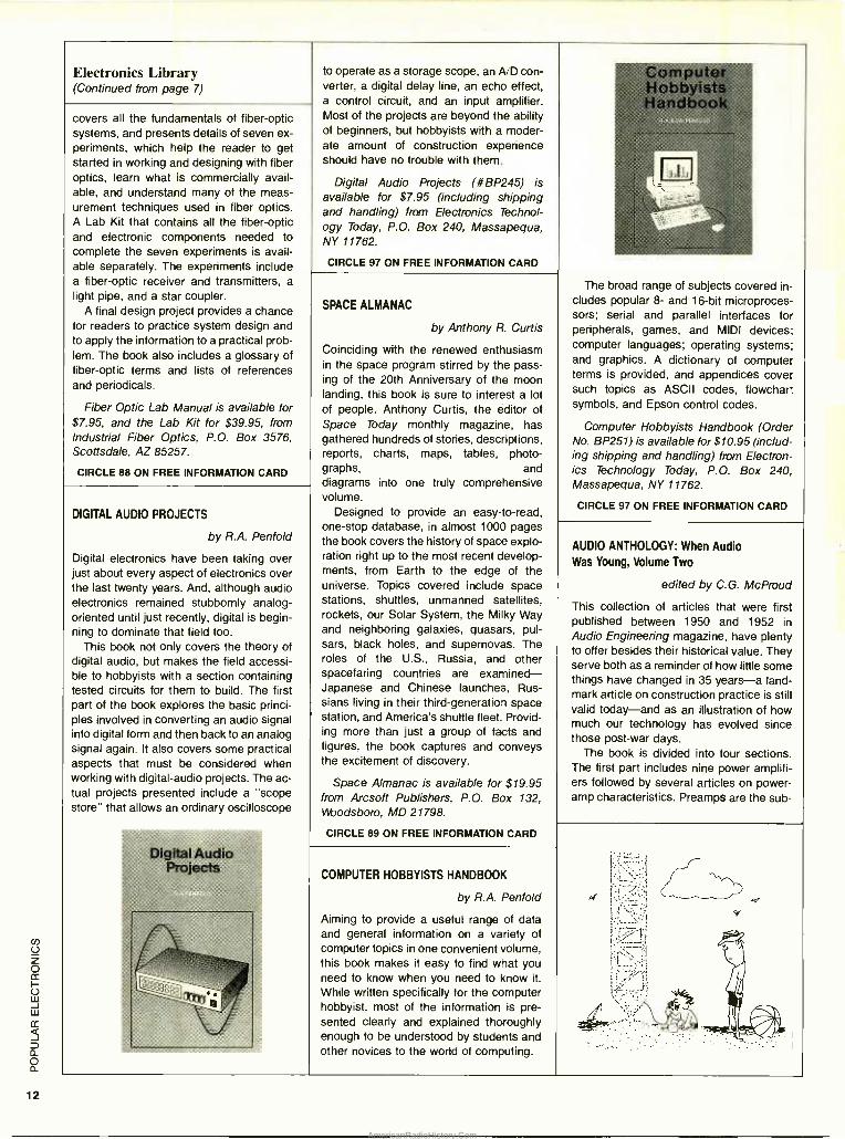
The broad range of subjects covered in- cludes popular 8- and 16 -bit microproces- sors; serial and parallel interfaces for peripherals, games, and MIDI devices. computer languages; operating systems and graphics. A dictionary of computer terms is provided, and appendices cover such topics as ASCII codes, flowchart symbols, and Epson control codes.
Computer Hobbyists Handbook (Order No. BP251) is available for $10.95 (includ- ing shipping and handling) from Electron- ics Technology Today, P.O. Box 240, Massapequa, NY 11762.
CIRCLE 97 ON FREE INFORMATION CARD
AUDIO ANTHOLOGY: When Audio Was Young, Volume Two
edited by C.G. McProud
This collection of articles that were first published between 1950 and 1952 in Audio Engineering magazine, have plenty to offer besides their historical value. They serve both as a reminder of how little some things have changed in 35 years -a land- mark article on construction practice is still valid today -and as an illustration of how much our technology has evolved since those post -war days.
The book is divided into four sections. The first part includes nine power amplifi- ers followed by several articles on power - amp characteristics. Preamps are the sub-
COMPUTER HOBBYISTS HANDBOOK
by R.A. Penfold
Aiming to provide a useful range of data and general information on a variety of computer topics in one convenient volume, this book makes it easy to find what you need to know when you need to know it.
While written specifically for the computer hobbyist, most of the information is pre- sented clearly and explained thoroughly enough to be understood by students and other novices to the world of computing.
AmericanRadioHistory.Com
ject of the second section, which also in-
cludes the first article on stereophonic re-
production and how it might be achieved by filtering of the mono signal. The third section focuses on loudspeakers, includ- ing resonant enclosures and port sizes, re-
flexed cabinets, how to deal with reso- nance peaks, and a survey of horn types, along with how to build several bass -en- hancing versions. The last section in-
cludes two tape- recording accessories -a portable interview amplifier and a tape
playback preamp. The book's editor, C.G. McProud,
helped found the Audio Engineering soci-
ety. He was editor and publisher of Audio Engineering in the pioneering days when
many of the projects presented in the magazine weren't yet being produced commercially.
Audio Anthology: When Audio Was
Young, Volume Two is available for $16.95 plus $1.75 shipping and handling from
Old Colony Sound Lab, P.O. Box 243, Pe-
terborough, NH 03458; Tel. 603 -924- 6371.
CIRCLE 84 ON FREE INFORMATION CARD
a professional recording engineer, it is full
of tips and shortcuts on everything from
what kind of equipment to choose to how
to package and present demo tapes. The book covers how to set up a studio
for the best sound quality and acoustics, and how to get the best results from mik-
ing, recording, and mixing. It includes pro-
fessional tips for training one's hearing, judging sound quality, and troubleshooting bad sound. Advice is given for on- location recording, and about protecting a musi-
cian's rights. The recent technology of digi-
tal sampling, sequencing, and MIDI are
also discussed.
Recording Demo Tapes at Home is
available for $19.95 from Howard W.
Sams & Company, 4300 West 62nd St.,
Indianapolis, IN 46268; Tel. 800-428 - SAMS.
CIRCLE 95 ON FREE INFORMATION CARD
RECORDING DEMO TAPES AT HOME
by Bruce Bartlett
Demo tapes are valuable tools for musi- cians in many ways. They provide a way to document musical ideas and progress; to audition for potential managers, club owners, and record companies; to enter contests; to send copies to friends and
relatives; to train new band members; and to start a professional studio production. With the new generation of small -scale
sound equipment that's available today, it's possible to put together professional-
Recording Demo Tapes at Home
sounding demo tapes in a home "studio" - without spending a fortune.
The equipment might be small, but it's
sophisticated, and getting the most out of
it requires a thorough understanding of
how it works, and of recording production in general. This book shows musicians all
they need to know about how to put a
home music studio to work, and does so
in plain, easy -to -read English. Written by
GLOSSARY OF MICROCOMPUTER
DATA ACQUISITION TERMS
compiled by MetraByte Corp.
Microcomputer data acquisition is used in
research & development, industrial /proc- ess control, communications, and auto-
matic test and measurements, to name just a few applications. This 23 -page book- let is a handy reference source in which almost 300 terms are defined. The defini- tions encompass data conversion, signal conditioning, and microcomputer systems and software.
Glossary of Microcomputer Data Acqui- sition terms is available at no charge from
MetraByte Corporation, 440 Myles Stan- dish Boulevard, Taunton, MA 02780; Tel.
508 -880 -3000.
CIRCLE 83 ON FREE INFORMATION CARD
CUSTOMIZE YOUR HOME
ENTERTAINMENT SYSTEM: TV
AND VCR ENHANCEMENT PROJECTS
by Steve Sokolowski
An unfortunate side -effect of the fast pace of technological developments is that to- day's cutting -edge video equipment can
become next month's "antique " -if not ob-
solete, then certainly no longer a state -of- the -art item. For those who are reluctant to invest big bucks in the consumer -elec- tronics game of chance, this book provides an alternative in the form of do- it- yourself upgrades for your old (or new) equipment. Twenty -two original projects, each de-
signed to transform TV's and VCR's into
more -sophisticated systems, are included. Along with the projects, the book offers a
hands -on guide to electronics, with full
coverage of the fundamentals ranging from electronic theory and components to
TALK IS
CHEAP. Have you heard? For less than $90 your AT or XT- compatible com- puter can talk! All it needs is the HV -2000 Computer Voice Kit from Heathkit.
Reading letters, transcriptions and computerized instruction can be easier and quicker than you ever thought possible. Computer games gain a new dimension. Your com- puter can even entertain children with stories and songs.
If you have a modem.
the HV -2000 Computer Voice will allow your computer to recite reference and research information from time- sharing services. Or, speak radio transmitted ASCII information.
The HV -2000 Computer Voice Card, containing speech synthesizer and audio amplifier, plugs into any AT or XT- compatible computer's expansion slot. An external speaker is also included. Versatile, Heath - developed software gives you a wide variety of voices and easy in- terface to high and low level languages.
The HV -2000 Computer Voice. At less than $90, talk IS cheap. To order, call toll -free 1- 800 -253 -0570. Use your Visa, MasterCard, Ameri- can Express or Heath Revolving Charge card. Use order code 218 -1 +07.
For your FREE Heathkit Catalog call 1- 800 -44 -HEATH
Heath Company i A subsidiary of Zenith Electronics Corporation
Prices, product availability and specifications are
subject to change without notice.
13
AmericanRadioHistory.Com
WORLD'S SMALLEST WEATHER STATION
THE AMAZING WEATHER COMPUTER THAI YOU CAN HOLD IN THE PALM OF YOUR HAY I
DIGITAR'S new WeatherPro weather station includes a computer, precision wind vane and speed sensor with mounting hardware, and 40 feet of cable. For only $175. With the optional, automatic -emptying Rain Collector (549.951 you can even monitor rainfall!
WIND RAINFALL fOpiional) WIND DIRECTION TIME OF DAY WIND CHILL AUTO SCAN WIND GUST RECORD METRIC/STANDARD
TEMPERATURE NICAD READY HVLOW TEMP RECORD ONE YEAR WARRANTY
Add $5.00 for shipping, plus sales lax for California deliveries. QUALITY ENGINEERING SINCE 1964
DIGITAR 3465 Diablo Avenue
MADE IN U.S.A. Hayward, CA 94545 WC & VISA ORDER TODAY: 1 -800- 678 -3669, ext. PE
M -F 7 AM -5:311 PM Pacific Tune.
74-Day Money -Back Guarantee FAX: 1- 415 -712 -9189
LEARN VIII CLEANING /MAINTENANCE /REPAIR EARN UP TO $1000 A WEEK, WORKING PART TIME FROM YOUR OWN HOME!
f NO Special
Tools or Equipment
Needed
THE MONEY MAKING OPPORTUNITY OF THE 1990'S
IF you are able to work with common small hand tools, and are familiar with basic electronics (i.e. able to use voltmeter, understand DC electronics)... .
IF you possess average mechanical ability, and have a
VCR on which to practice and learn. ...then we can teach YOU VCR maintenance and repair! FACT: up to 90% of ALL VCR malfunctions are due to simple MECHANICAL or ELECTRO- MECHANICAL breakdowns! FACT: over 77 million VCRs in use today nationwide! Average VCR needs service or repair every 12 to 18 months! Viejo's 400 PAGE TRAINING MANUAL (over 500 pho- tos and illustrations) and AWARD -WINNING VIDEO TRAINING TAPE reveals the SECRETS of VCR mainte- nance and repair -"real world" information that is NOT available elsewhere! Also includes all the info you'll need regarding the BUSINESS -SIDE of running a successful service op- eration!
FREE INFORMATION CALL TOLL -FREE 1- 800 -537 -0589
Or write to: Viejo Publications 3540 Wilshire BL. STE 310
Los Angeles, CA 90010 Dept HO
14 CIRCLE 8 ON FREE INFORMATION CARD
Electronics Library
techniques of project construction such as soldering and making printed- circuit boards.
Some of the projects include a TV -ste- reo adapter to convert an older TV or VCR to receive stereo broadcasts, and a stereo simulator to convert a mono output to a stereo sound -alike. A rear -speaker ambi- ence amplifier can be used with stereo output to decode and simulate surround
Customize Your Home Entertainment System: Nand VCR
Enhancement Projects -
5rowSnkololt5k1
sound, and a graphic equalizer lets the user tune the audio output to his prefer- ence. Noise- reduction circuits are also presented.
Customize Your Home Entertainment System: TV and VCR Enhancement Pro- jects is available for $15.95 from TAB Books Inc., Blue Ridge Summit, PA 17294 -0850; Tel. 1- 800 -233 -1128.
CIRCLE 98 ON FREE INFORMATION CARD
USEFUL NETWORK THEOREMS
with Applications
by Dr. Harry E. Stockman
The author of this book, a former U.S.A.F. scientist, professor of electrical engineer- ing, and independent researcher has as- sembled a no- nonsense, direct presenta- tion of common network theorems, as well as several of his own new theorems. While intended for Electrical Engineering students, the book provides a reference source and historical notes that will inter- est engineers as well.
The book begins with a review of com- mon network theorems -such as the Su- perposition Theorem, the Reciprocity Theorem, and dependent- source theo-
. rems -and proceeds to more specific the- orems. The basic Helmholtz' Equivalent Generator Theorem is considered in depth. That and the useful Mayer's Source Transformation Theorem, are ex- plained in detail in many of the worked -out problems that are presented in the book's "Applications" section.
Time -saving techniques are used wher-
ever possible. Many of the problems are applied in the cisoidal state, with complex frequency aiding a quick solution. For in- stant reference,. each solution is indexed with the number of each theorem used. The appendix includes a number of useful techniques, including coverage of matri- ces, twoports, initial conditions, and simi- lar tabulations.
Useful Network Theorems with Applica- tions is available for $11.25 (including shipping) in the U.S. and Canada from Sercolab Company, Box 767, East Den- nis, MA 02641.
CIRCLE 82 ON FREE INFORMATION CARD
RF FILTERS FOR HF, VHF, UHF
RADIO & OTHER RF SYSTEMS:
5 1000 MHZ
Microwave Filter Company, Inc.
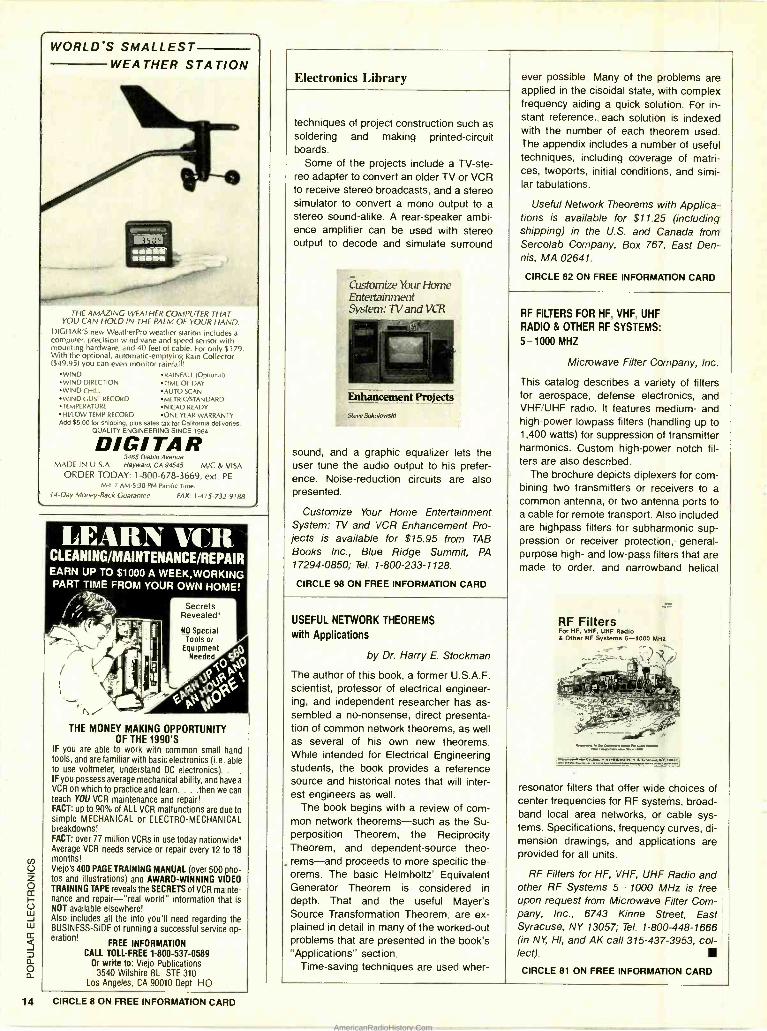
This catalog describes a variety of filters for aerospace, defense electronics, and VHF /UHF radio. It features medium- and high -power lowpass filters (handling up to 1,400 watts) for suppression of transmitter harmonics. Custom high -power notch fil- ters are also described.
The brochure depicts diplexers for com- bining two transmitters or receivers to a common antenna, or two antenna ports to a cable for remote transport. Also included are highpass filters for subharmonic sup- pression or receiver protection, general - purpose high- and low -pass filters that are made to order, and narrowband helical
RF Filters
resonator filters that offer wide choices of center frequencies for RF systems, broad- band local area networks, or cable sys- tems. Specifications, frequency curves, di- mension drawings, and applications are provided for all units.
RF Filters for HF, VHF, UHF Radio and other RF Systems 5 - 1000 MHz is free upon request from Microwave Filter Com- pany, Inc., 6743 Kinne Street, East Syracuse, NY 13057; Tel. 1- 800 -448 -1666 (in NY, HI, and AK call 315 -437 -3953, col- lect).
CIRCLE 81 ON FREE INFORMATION CARD
AmericanRadioHistory.Com
1.1 _ IIIIIII
New Products To obtain additional information products covered in this section manu/iuturer, please circle the
number 00 the Free Information
llil. - '
on new
from the
item's code
Card
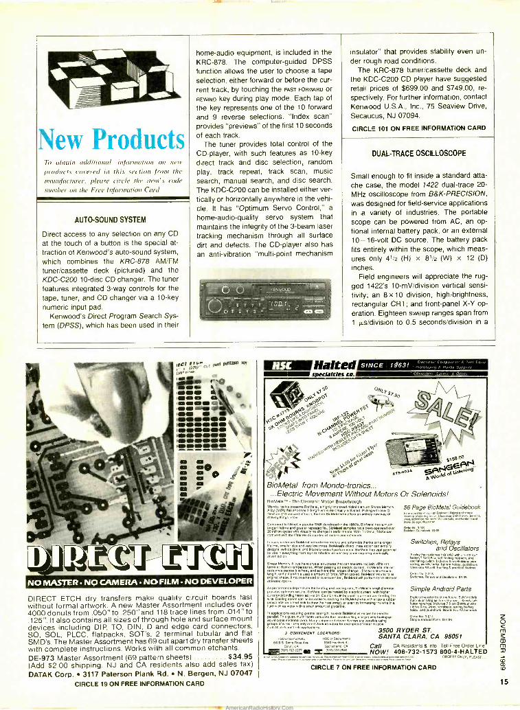
home KRC function selection, rent REWIND
the and provides of
CD- direct play, search, The fleetly de. home
tracking dirt an
-audio equipment, is included in the -878. The computer -guided DPSS
allows the user to choose a tape either forward or before the cur
track, by touching the FAST FORWARD Or
key during play mode. Each tap of
key represents one of the 10 forward 9 reverse selections. "Index scan"
"previews" of the first 10 seconds
The each track.
tuner provides total control of the player, with such features as 10 -key
track and disc selection, random track repeat, track scan, music
manual search, and disc search. KDC -C200 can be installed either ver
or horizontally anywhere in the vehi It has "Optimum Servo Control," a
-audio -quality servo system that maintains the integrity of the 3 -beam laser
mechanism through all surface and defects. The CD- player also has
anti -vibration "multi -point mechanism
insulator" that provides stability even un- der rough road conditions.
The KRC -878 tuner /cassette deck and the KDC-C200 CD player have suggested retail prices of $699.00 and $749.00, re- spectively. For further information, contact Kenwood U.S.A., Inc., 75 Seaview Drive,
Secaucus, NJ 07094.
CIRCLE 101 ON FREE INFORMATION CARD
DUAL -TRACE OSCILLOSCOPE
Small enough to fit inside a standard acre
the case, the model 1422 dual trace 20
MHz oscilloscope from B &K- PRECISION,
was designed for field- service applications in a variety of industries. The portable scope can be powered from AC, an op
tional internal battery pack, or an external 10 -16 -volt DC source. The battery pack
fits entirely within the scope, which meas-
ures only 41/2 (H) x 81/2 (W) x 12 (D)
inches. Field engineers will appreciate the rug-
ged 1422's 10 -mV /division vertical sensi- tivity; an 8 x 10 division, high -brightness, rectangular CRT; and front -panel X -Y op- eration. Eighteen sweep ranges span from
1µs /division to 0.5 seconds /division in a
AUTO -SOUND SYSTEM
Direct access to any selection on any CD
at the touch of a button is the special at-
traction of Kenwood's auto -sound system, which combines the KRC -878 AM /FM
tuner /cassette deck (pictured) and the KDC -C200 10 -disc CD changer. The tuner features integrated 3 -way controls for the tape, tuner, and CD changer via a 10 -key numeric input pad.
Kenwood's Direct Program Search Sys- tern (DPSS), which has been used In their
- C' u,
C ` CO °
®Halted specialties ca.1
50
Otv O
eQOt ' \ JPO`P PP
cO
aP?pFp
Z 6O
P É P
PSJ p*0
SG P0QV,PvEP E ti,'G P,P?5,p PSkk
NEJ SO < Ifi?c` Elb "ktO COY. g0 St6
gBgQaCaes mis o
s o
ßsú NO MASTER NO CAMERA NO FILM NO DEVELOPER
DIRECT ETCH dry transfers make quality circuit boards fast without formal artwork. A new Master Assortment includes over 4000 donuts from .050" to .250" and 118 trace lines from .014" to .125 ". It also contains all sizes of through hole and surface mount devices including DIP, TO, DIN, D and edge card connectors, SO, SOL, PLCC, flatpacks, SOT's, 2 terminal tubular and flat SM D's. The Master Assortment has 69 cut apart dry transfer sheets with complete instructions. Works with all common etchants. DE -973 Master Assortment (69 pattern sheets) $34.95 (Add $2.00 shipping. NJ and CA residents also add sales tax)
DATAK Corp. 3117 Paterson Plank Rd. N. Bergen, NJ 07047 CIRCLE 19 ON FREE INFORMATION CARD
$G198E00AN
pT5-B03A ¡ANSwf.rg.
BioMetal from Mondo- tronics... ...Electric Movement Without Motors Or Solenoids!
BioMetal" - The Electronic Motion Breakthrough Mondo.honke presents BoMetS, a highly Improved Mckel- Iltenium Shape Memory Alloy (SMA) that shortens In length when electrically activated. Pulling with over 3 Newtons (10 Bono°°) of bee, the min BbMmel wire opera an merely new way of making Things move.
Compared to Nltinol, a popular SMA developed In the IBaO., B.Me41 Ms a mud longer lifetime and greeter repeatability. BloMelai samples have been operated Over 20 reitlion cycles with WrMIy no charge in performance. With BioMetal. SMAt awn compete with the lifetimes demanded of motors end solenoids
in many instances BIBMeraI outperforms motors and solenoids thanks to Its longer lifetime, smaller size end very low mass. BloMe4 ra direct action n simpli designs, reduce cosh, end Increase overall performance. BloMetal has vast potential lor use in everything from toys to robotics. almost arty dace repairing electrically driven argon
...Memory Alloys have crystal vector,. that can assume redicaIIy dlllerenl
engel.erd pullawme ae'bleaemmrctnlol tortes WMncooled, TBroMeW reNms el4 original shape. If not overheated or on,t,Mrd.d, BloMelel wIll perform for millions of repealed cycle..
As performance depends Its the heating and cooing rate. B1oMetars smell diameter provides optimum results. BioMetal can be heated by &ache omen I, with higher
wirrents prodding feeler activation. Caution mull be used to prevent overheating the
e. cooling speed can be Increase by ling the BleMelal wire with silicone rubber (which
& ea as .at
WM a 1l amoouunt of p cerIne. awn by immersing lie wire lit.
In a Ze.1UOm rpubkg gaoler evangel. eewrei eloMe4i wo-e. can Se used m
lords M distinct temperatures. When passing an electric arment, Blo tars Internal
arel I. Tho aloa mach Iaelen'°°Come men would a skgle larger wire naving ac actinne on
al td deon drces pee pear
muscle al wi ee . one only needs look el nava Iw eeemdes of linear muscle convections acta their applications.
3500 RYDER ST. 3 CONVENIENT LOCATIONS: SANTA CLARA, CA 95051 HSC d Sta N50 t.
OM S. santa Roas Ave. 55x9 mento. St.
Comb. CA Sacramento. CA Call CA Residents & Info Toll Free Order Line 000)7922273 tail d2a'5 NOW! 408 -732 -1573 800 -4- HALTED
ORDERS ONLY, PLEASE...
56 Page BioMetal Guidebook EmnW.Immmxwn on Bò950.1, Nenwl end sM1roa
myaMS panxtl0lxuassrMnxmry.arl'.. M1N.I n xhotls. WXn wwM, mxNwsme ane
BMAIóultl009. faa5
Switches, Relays and Oscillators
A nary 01.5 Vest
110 VAC wIth 1,. and
Von batty? Vest Also sewOm.ing contacts, and
asclaati g switch. Includesry5 cm BbMMtel wire.
Ilaere nn MwÌI É stag heic knl .rinnNwok
Other No. 3.
Swechee. Re0lay15 s enti Oscillators Seas
Simple Android Parts Expo. the robotics of Ih. Idure. Bapd modals Ink It living systems Ike tan. elbows. Imis fiunsrirg wogs. Include.) 5 an BleM.41 vme rubber tube, wires, workbase spring, battery holder aid guidebook Needs no AA be... Orda No 3-Ola Simple Android Pads slags
CIRCLE 7 ON FREE INFORMATION CARD
AmericanRadioHistory.Com
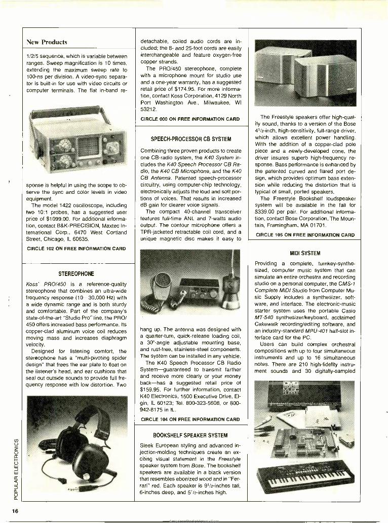
16
New Products
1/2/5 sequence, which is variable between ranges. Sweep magnification is 10 times, extending the maximum sweep rate to 100 -ns per division. A video -sync separa- tor is built -in for use with video circuits or computer terminals. The flat in -band re-
sponse is helpful in using the scope to ob- serve the sync and color levels in video equipment.
The model 1422 oscilloscope, including two 10:1 probes, has a suggested user price of $1099.00. For additional informa- tion, contact B&K- PRECISION, Maxtec In-
ternational Corp., 6470 West Cortland Street, Chicago, IL 60635.
CIRCLE 102 ON FREE INFORMATION CARD
detachable, coiled audio cords are in- cluded; the 8- and 25 -foot cords are easily interchangeable and feature oxygen -free copper strands.
The PRO /450 stereophone, complete with a microphone mount for studio use and a one -year warranty, has a suggested retail price of $174.95. For more informa- tion, contact Koss Corporation, 4129 North Port Washington Ave., Milwaukee, WI 53212.
CIRCLE 000 ON FREE INFORMATION CARD
STEREOPHONE
Koss' PRO /450 is a reference -quality stereophone that combines an ultra -wide frequency response (10- 30,000 Hz) with a wide dynamic range and is both sturdy and comfortable. Part of the company's state -of- the -art "Studio Pro" line, the PRO/ 450 offers increased bass performance. Its copper -clad aluminum voice coil reduces moving mass and increases diaphragm velocity.
Designed for listening comfort, the stereophone has a "multi- pivoting spider design" that frees the ear plate to float on the listener's head, and ear cushions that seal out outside sounds to provide full fre- quency response with low distortion. Two
SPEECH -PROCESSOR CB SYSTEM
Combining three proven products to create one CB -radio system, the K40 System in- cludes the K40 Speech Processor CB Ra- dio, the K40 CB Microphone, and the K40 CB Antenna. Patented speech -processor circuitry, using computer -chip technology, electronically adjusts the loud and soft por- tions of voices. That results in increased dB gain for clearer voice signals.
The compact 40- channel transceiver features full -time ANL and 7 -watts audio output. The contour microphone offers a TPR- jacketed retractable coil cord, and a
unique magnetic disc makes it easy to
hang up. The antenna was designed with a quarter -turn, quick -release loading coil, a 30° -angle adjustable mounting base, and rust -free, stainless -steel components. The system can be installed in any vehicle.
The K40 Speech Processor CB Radio System -guaranteed to transmit farther and receive more clearly or your money back -has a suggested retail price of $159.95. For further information, contact K40 Electronics, 1500 Executive Drive, El- gin, IL 60123; Tel. 800 -323 -5608, or 800- 942 -8175 in IL.
CIRCLE 104 ON FREE INFORMATION CARD
BOOKSHELF SPEAKER SYSTEM
Sleek European styling and advanced in-
jection- molding techniques create an ex- citing visual statement in the Freestyle speaker system from Bose. The bookshelf speakers are available in a black version that resembles ebonized wood and in "Fer- rari" red. Each speaker is 91/2- inches tall, 6- inches deep, and 51/2- inches high.
The Freestyle speakers offer high -qual- ity sound, thanks to a version of the Bose 4'/2 -inch, high -sensitivity, full -range driver, which allows excellent power handling. With the addition of a copper -clad pole piece and a newly -developed cone, the driver insures superb high- frequency re- sponse. Bass performance is enhanced by the patented curved and flared port de- sign, which provides optimum bass exten- sion while reducing the distortion that is typical of small, ported speakers.
The Freestyle Bookshelf loudspeaker system will be available in the fall for $339.00 per pair. For additional informa- tion, contact Bose Corporation, The Moun- tain, Framingham, MA 01701.
CIRCLE 105 ON FREE INFORMATION CARD
MIDI SYSTEM
Providing a complete, turnkey- synthe- sized, computer music system that can simulate an entire orchestra and recording studio on a personal computer, the CMS -1
Complete MIDI Studio from Computer Mu- sic Supply includes a synthesizer, soft- ware, and interface. The electronic -music starter system uses the portable Casio MT -540 synthesizer /keyboard, acclaimed Cakewalk recording /editing software, and an industry- standard MPU -401 half -slot in- terface card for the PC.
Users can build complex orchestral compositions with up to four simultaneous instruments and up to 16 simultaneous notes. There are 210 high -fidelity instru- ment sounds and 30 digitally- sampled
AmericanRadioHistory.Com
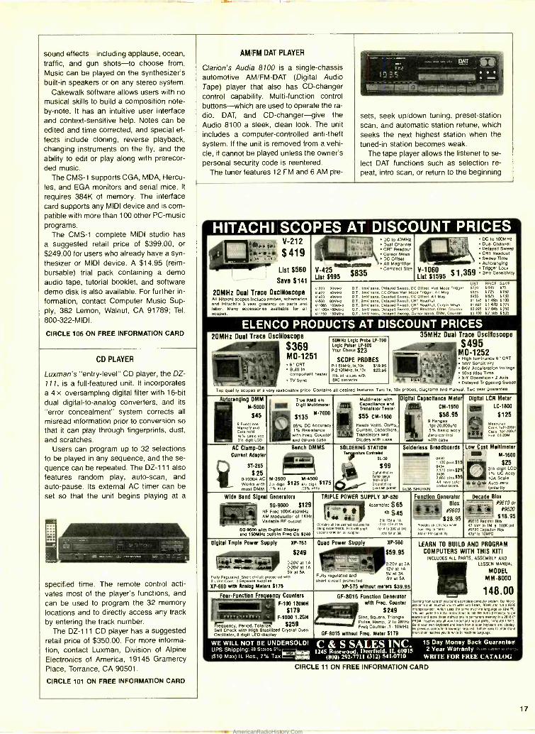
sound effects -including applause, ocean, traffic, and gun shots -to choose from. Music can be played on the synthesizer's built -in speakers or on any stereo system.
Cakewalk software allows users with no musical skills to build a composition note - by -note. It has an intuitive user interface and context -sensitive help. Notes can be
edited and time corrected, and special ef- fects include cloning, reverse playback, changing instruments on the fly, and the ability to edit or play along with prerecor- ded music.
The CMS -1 supports CGA, MDA, Hercu- les, and EGA monitors and serial mice. It
requires 384K of memory. The interface card supports any MIDI device and :s com- patible with more than 100 other PC -music programs.
The CMS -1 complete MIDI studio has a suggested retail price of $399.00, or $249.00 for users who already have a syn- thesizer or MIDI device. A $14.95 (reim- bursable) trial pack containing a demo audio tape, tutorial booklet, and software demo disk is also available. For further in-
formation, contact Computer Music Sup- ply, 382 Lemon, Walnut, CA 91789; Tel.
800 -322 -MIDI.
CIRCLE 106 ON FREE INFORMATION CARD
AM /FM DAT PLAYER
Clarion's Audia 8100 is a single- chassis automotive AM /FM -DAT (Digital Audio Tape) player that also has CD- changer control capability. Multi- function control buttons -which are used to operate the ra-
dio, DAT, and CD- changer -give the Audio 8100 a sleek, clean look. The unit includes a computer -controlled anti -theft system. If the unit is removed from a vehi- cle, it cannot be played unless the owner's personal security code is reentered.
The tuner features 12 FM and 6 AM pre-
DNT
sets, seek up /down tuning, preset- station scan, and automatic station retune, which seeks the next highest station when the tuned -in station becomes weak.
The tape player allows the listener to se- lect DAT functions such as selection re-
peat, intro scan, or return to the beginning
CD PLAYER
Luxman's "entry -level" CD player, the DZ- 111, is a full- featured unit. It incorporates a 4 x oversampling digital filter with 16 -bit dual digital -to- analog converters, and its
"error concealment" system corrects all
misread information prior to conversion so that it can play through fingerprints, dust, and scratches.
Users can program up to 32 selections to be played in any sequence, and the se- quence can be repeated. The DZ -111 also features random play, auto -scan, and auto -pause. Its external AC timer can be set so that the unit begins playing at a
specified time. The remote control acti- vates most of the player's functions, and
can be used to program the 32 memory locations and to directly access any track by entering the track number.
The DZ -111 CD player has a suggested retail price of $350.00. For more informa- tion, contact Luxman, Division of Alpine Electronics of America, 19145 Gramercy Place, Torrance, CA 90501.
CIRCLE 101 ON FREE INFORMATION CARD
HITACHI SCOPES AT DISCOUNT PRICES V 2 DC to 40
Dual Chal CRT Readout Cursor Meas DC Offset oar ;;\ All Magniller
- +L_
Delayed Sweep CRT Readout Sweep Time Autoranging
V -1060 Trigger Lock
List $1595 $1 ¡359 2mV Sensitivity
A -21 11, QQ -(
$ 4 1 9
List 5560
Save $141
20MHz Dual Trace Oscilloscope All Hitachi scopes Include probes, schematics and Hitachi's 3 year guaranty on parts and labor. Many accessories available for all scopes.
compact s +2e V -425 List $995 $835
LIST PRICE SAVE
V -223 20MHZ D.T.. ImV sans, Delayed Sweep, DC Off set. Vert Mode Tripper $770 $695 S75 VV22 40MHz ay.. 1i-fly sons, DC Of feet Vert M de Trigger, All Map 5875 $725 $150 V423 40MMZ DT., In sans, Delayed Sweep. DC Offset, Alt Hap $955 $825 $ 130
V 880 60MHZ D.T., 2mV tens, Delayed Sweep, C T Readout $1,195 $1.095 S100 V 1085 loomHz D.T., 2mV sane, Delayed Sweep. C T Readout. Cursor Meas $1.895 $1,670 $225
-1100At00MMZ 0 T., 1mO sans, Delayed Sweep, C T Readout. DOM, Counter $2,295 $2.045 $ 250 V -1150 150M1Z 07 ., 1mV sere, Delayed Sweep, Cursor Metre, DVM. Counter $3,100 $2,565 $ 535
ELENCO PRODUCTS AT DISCOUNT PRICES 20MHz Dual Trace Oscilloscope 35MHz Dual Trace Oscilloscope
_. $369 r MO -1251
_ fi" CRT
r ...`
_ Built In component teeter
Eyr TV Sync
50MHz Logic Robe LP -700 Logic Pillow LP -600 your Choice 523
SCOPE PROBES p.165MHZ,14.10x 819.aá P.2100MHZ.1x,10x 523.95 FN$ all scopes with BNC connector
, $495 ,- .,.:.. MO -1252 /p
p High luminance 6 "CRT ,e* 19V Sensitivity
6KV Acceleration Voltage fi 10ns
Operation 1 X y Operation Z Axis Delayed Triggering Swam
Top quality scopes at a ery reasonable price. Contains all desired features. Twc 1 . 10 probes, diagrams and manua . Two year guarantee
toranging 01AM
M -5000
$45
Memory end Date bold N% Daelc acc 3N digit LCO
Maltlnlater with Capacitance and Translator Taatar
p;t:; and
Digital Capacitance Mete
CM-1550
,1 p420,000ufd 5% basic act
Zero control i with case
Digital LCR Meter al LC -1800 True RMS 415
mill Digit Multlmatw
M -7000 $135 .s,
.1% witY and
AC Clamp -On
Current Adopter
ST -265
, 25 01000A AC
_ Works with most DMM
Bench OMMS -
SOLDERING STATION Iran DMbeá d
$99 oI 11Ldspuy g Temp range
3rOund69F Grounded lip
Overheat Prmect
Solderlass Breadboards Low Cost Multlmeter
M -1600
$25
aaai 930pins$1 2.t70 pi ^s $25 8438 2,860 pine i3á All nave color
3'h digit LCD ® 1% DC Accy Scale M.3500 M -4500
3vx digit í125 avr di d $175 t% eccy 05% ccy
st RI 4iW Auto zero Auto _ ¡polarity coded posts 9436 SHOWN
Wide Band Signal Generators TRIPLE POWER SUPPLY XP -620
Z Assembled $ 65 E s Kit $45 ' Of
2 to tau a1 IA. Conte its an the desired lulures tar -2 to ,15V at IA
doing expenmems Futures shod (or a to 30V at 'Al urcunprolecpon
a" .0... arc] Suet 3.
Function Generator Decade Blox
y+JI
- 09610 Reslsib 47 Ohm to 1M 19810 Gppaaccltor I7pf to 10MF0
N9 #96 or
I X620 i+
518.95 Bl01,
a 100k poi Blm
0 ' ' $28.95
Provides slne.lr,s0 wave
vwn imam IMMZ AM or FM cap abrph
30-9000 $129 i z 'Ai RF Freq 100K-450MHz
AM Modulation of 1 KHZ
T. ti Variable RF output
SD.9500 with Digital Display and 150MMZ built -In Frai Ctr $240
Digital Triple Power Supply XP -765
$249 'ET 020V at lA
Quad Power Supply 0P -580
$59.95 ..- -
2.20V at 2A c 12V
5V att3AA Fully regulated and .SV et SA short circuit protected
XP -575 without meters $39.95
LEARN TO BUILD AND PROGRAM
COMPUTERS WITH THIS KIT! INCLUDES ALL FARTS, ASSEMBLY AND
LESSON MANUAL
MODEL - MM-BDDD
- '- 148.ÚU
wMelle,a 0.20V at lA 5V at 5A
Fully Regulated, Short cI wt prnlecled wltn 2 Llmil Cont., 3 Separate S.W. s
XP -660 with Analog Meters $175
Four-Function Fre uency Counters OF -8016 Function Generator with Fra Courtier Q'
,r-c1 $249 L - Sine, Square, Triangle Pulse, Ramp, .2 to 2MHz Freq Counter .1 10MHz
OF -8015 without Freq. Motor $179
Surnng tram scratch you build a comp.. cmroulx system Our Mam- Mantar trainer teaches you to wale into RAMS. MOMS and run a 8085 microprocessor. which uses tM same machine language M IBM PC
You will vente the Mate instructions to wl me 8085 proonsor to pet
sorted and store these Instructions In permanent memory Ina 2816 E' PROM Teachn you all about maul and output eons, computer timers Build your own keyboard and learn how to man keyboard and display Nd prevmus Cmgt.. Otdps required Simple easy to understand Instruction Inches you to write In machine language
-' I
F -100 12p0MH
$179 F -1000 1,20H
Monty, period, rolal 5259 Self Check with High Stabilized Crystal Oven Oscillator, 8 digit LED display
WE WILL NOT BE UNDERSOLD! UPS Shipping:48 Slates 5 ̂ e 1 ($10 Max) IL Res., 7 % Tax 1-
C & S SALES INC. 1245 Rosewood, Deerfield, I1. 60015
(ROO) 292 -7711 (312) 541 -0710
15 Day Money Back Guarantee 2 Year Warranty
W'NITF'. FOR FREE CATALOG
CIRCLE 11 ON FREE INFORMATION CARD
17
AmericanRadioHistory.Com
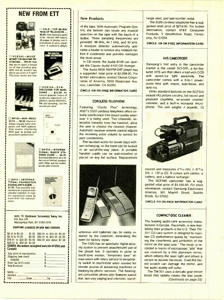
NEW FROM ETT
C] PCP105 -MAKE MONEY FROM HOME RE- CORDING $10.00. Now that you've spent a fortune on all that recording gear, MIDI and all, wouldn't you like to get some of it back? This book shows you how.
BP182 -MIDI PROJ- ECTS $6.95. How to in- terface popular home com- puters with MIDI systems. Also covers interfacing MIDI gear to analog and percussion synthesizers.
BP85- INTERNA- TIONAL TRANSISTOR EQUIVALENTS GUIDE $7.50. Find possible sub- stitutions fora popular user - oriented selection of mod- ern transistors made by more than 100 manufac- turers.
TELE -THE INVEN- TION OF TELEVISION $9.95. How television came to be. Packed with history. 36 -pages of photos and il- lustrations of early equip- ment. A collector's delight.
PCP106 -SYN- THESIZERS FOR MUSI- CIANS $10.00. All current popular forms of synthesis explained. LA, additive, phase distortion, FM and sampling. Get the sounds you want.
MIDI Projcots
BP255- INTERNA- TIONAL RADIO STA- TIONS GUIDE $8.95. Essential reference work for the casual listener, amateur radio DXer and the profes- sional radio monitor.
L
MAIL TO: Electronic Technology Today, Inc. P.O. Box 240 Massapequa Park, NY 11762 -0240
SHIPPING CHARGES IN USA ANO CANADA
$0.01 to $5.00 ...$1.25 $30 01 to $40.00 $5.00 $5.01 to 10.00 ...$2.00 $40 01 to $50.00 $6.00 $10.01 to $20.00 $3.00 $50 01 and above $7.50 $20.01 to $30.00 $4.00 SORRY, No orders accepted outside of USA and Canada
Total price of merchandise $ Shipping (see chart) $
Subtotal $ Sales Tax (NYS only) $ Total Enclosed $
Name Address City State Zip
a
New Products
of the tape. With Automatic Program Con- trol, the listener can locate any musical selection on the tape with the touch of a button. Three sampling frequencies are provided: 48 kHz, 44.1 kHz, and 32 kHz. A moisture detector automatically acti- vates a heater to remove any moisture be- fore it condenses and possibly damages the drum areas.
In CD mode, the Audia 8100 can oper- ate the Clarion Audio 6100 CD changer.
The Audia 8100 AM /FM -DAT player has a suggested retail price of $2,299.00. For further information, contact Clarion Corpo- ration of America, 5500 Rosecrans Ave- nue, Lawndale, CA 90260.
CIRCLE 108 ON FREE INFORMATION CARD
CORDLESS TELEPHONE
Featuring "Clarity Plus" technology, AT &T's 5320 cordless telephone offers vir- tually interference -free sound quality wher- ever it is being used. Two channels, se- lectable instantly from the handset, allow the user to choose the clearest channel. Automatic receiver -volume control adjusts the incoming voice volume to correct for poor connections.
The handset works for seven days with- out recharging, so the base can be tucked in an out -of- the -way place. A portable handset cradle can be wall- mounted or placed on any flat surface. Replacement
antennas and batteries can be easily in- stalled by the customer, eliminating the need for factory repair.
The 5320 has an automatic digital secu- rity system to prevent unauthorized use of the phone line. It operates in pulse or touch -tone modes; "temporary tone" al- lows users with rotary service to temporar- ily switch to touch -tone when needed for remote access of answering machines or banking -by -phone services. The hearing - aid compatible phone also features speed dial, two -way paging and intercom, out -of-
range alert, and last- number redial. The 5320 cordless telephone has a sug-
gested retail price of $219.00. For further information, contact AT &T Consumer Products, 5 Woodhollow Road, Parsip- piny, NJ 07054.
CIRCLE 109 ON FREE INFORMATION CARD
VHS CAMCORDER
Samsung's first entry in the camcorder market is the model SCF500, a full -fea- tured VHS unit that offers a half -inch CCD with seven -lux light sensitivity. The camcorder comes with a 6 -to -1 power - zoom lens with macro, auto -focus, and auto -iris.
Other standard features on the SCF500 include HQ picture circuitry, full record and playback capability, on- screen counter/ calendar, and a built -in monaural micro- phone. The unit weighs 4 pounds, 13
ounces and measures 415/16 (W) x 813/16
(H) x 133/16 (D). It comes with cables, a battery, and a battery recharger.
The SCF500 camcorder has a sug- gested retail price of $1,199.00. For more information, contact Samsung Electronics America, 301 Mayhill Street, Saddle Brook, NJ 07662.
CIRCLE 110 ON FREE INFORMATION CARD
COMPACT -DISC CLEANER
The leading audio -care accessory manu- facturer in Europe, Trackmate, is now mar- keting their products in the U.S. Their TM- 351 CD -care system is designed to main- tain CD performance quality by "maintain- ing the cleanliness and perfection of the mirror on the label side." The music is re- corded in tracks of microscopic "pits" that are covered by a thin aluminum mirror, which reflects the laser light and allows a sensor to decode the music. Even the tini- est scratch can damage the mirror, and the audio quality will suffer.
The TM -351 uses a delicate gear- driven brush that radially cleans the disc inside
(Continued on page 22)
AmericanRadioHistory.Com
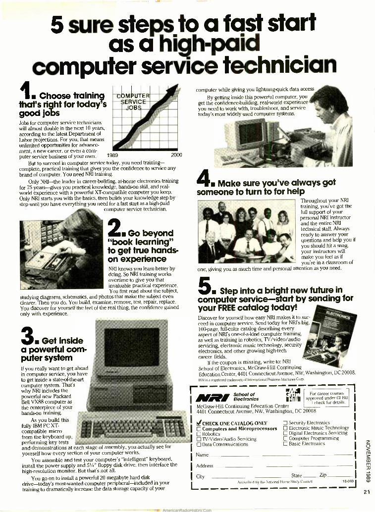
5 sure steps to a fast start as a high -paid
computer service technician I Choose training
that's right for today's good jobs Jobs for computer service technicians will almost double in the next 10 years, according to the latest Department of Labor projections. For you, that means unlimited opportunities for advance- ment, a new career, or even a com- puter service business of your own. 1989 2000
But to succeed in computer service tochy, you need training - complete, practical training that gives you the confidence to service any brand of computer. You need NRI training.
Only NRI -the leader in career- building, at -home electronics training for 75 years -gives you practical knowledge, hands-on skill, and real - world experience with a powerful XT-compatible computer you keep. Only NRI starts you with the basics, then builds your knowledge step by step until you have everything you need for a fast start as a high -paid
computer service technician.
2 Go beyond "book learning" to get true hands - on experience NRI knows you learn better by doing. So NRI training works overtime to give you that invaluable practical experience. You first read about the subject,
studying diagrams, schematics, and photos that make the subject even clearer. Then you do. You build, examine, remove, test, repair, replace. You discover for yourself the feel of the real thing, the confidence gained only with experience.
3 Get inside a powerful corn - puter system If you really want to get ahead in computer service, you have to get inside a state-of-the-art computer system. That's why NRI includes the powerful new Packard Bell VX88 computer as the centerpiece of your hands-on training.
As you build this fully IBM PC XT- compatible micro from the keyboard up, Ill performing key tests and demonstrations at each stage of assembly, you actually see for
yourself how every section of your computer works.
You assemble and test your computer's "intelligent" keyboard, install the power supply and 51/4" floppy disk drive, then interface the high -resolution monitor. But that's not all.
You go on to install a powerful 20 megabyte hard disk drive-today's most -wanted computer peripheral- included in your training to dramatically increase the data storage capacity of your
computer while giving you lightning-quick data access
By getting inside this powerful computer, you get the confidence -building, real -world experience you need to work with, troubleshoot, and service today's most widely used computer systems.
4 Make sure you've always got someone to turn to for help
Throughout your NRI training, you've got the full support of your personal NRI instructor and the entire NRI technical staff. Always ready to answer your questions and help you if
you should hit a snag, your instructors will make you feel as if
you're in a classroom of
one, giving you as much time and personal attention as you need.
5. Step into a bright new future in computer service -start by sending for your FREE catalog today! Discover for yourself how easy NRI makes it to suc- ceed in computer service. Send today for NR's big, 100 -page, full-color catalog describing every aspect of NRI's one-of- a-kind computer training, as well as training in robotics, TV /video /audio servicing, electronic music technology, security electronics, and other growing high -tech career fields.
If the coupon is missing, write to: NRI
School of Electronics, McGraw -Hill Continuing Education Center, 44D1 Connecticut Avenue, NW, Washington, DC 20008.
IBM is a registered trademark of International Business Machines Corp.
MA,School of Electronics
71 ,.141 141
WIN McGraw -Hill Continuing Education Center 4401 Connecticut Avenue, NW, Washington, DC 20008
For career courses approved under GI Bill
check for details.
1'CHECK ONE CATALOG ONLY Computers and Microprocessors Robotics TV /Video /Audio Servicing Data Communications
Security Electronics Electronic Music Technology Digital Electronics Servicing Computer Programming Basic Electronics
Name
Address
City State Zip
L Accredited by the National Home Study Council , 8.t169 t
21
AmericanRadioHistory.Com
22
New Products (Continued from page18)
its storage case -with no unnecessary handling. A small central platform supports the disc and allows the CD to "float" in its box. The brush connects to the center of the disc case and maintains even contact with the disc, gently cleaning the mirror side while the other side floats. That
method prevents dirt from being forced into the surface of the CD.
The Trackmate system also includes a felt pen that contains a proprietary clean- ing solution to "assure optical perfection for maximum laser transmission." The pen precisely controls the amount of cleaning solution released, preventing dripping and over -dosing.
The TM -351 CD- cleaning system has a suggested retail price of $19.95. For more information, contact Trackmate, I.D.A. En- terprise Centre, East Wall Road, Dublin 3, Ireland.
CIRCLE 112 ON FREE INFORMATION CARD
SPEAKER PROTECTION DEVICE
For those who like their music loud, Allison Acoustics' Power Shield could come in handy. Tne loudspeaker -protection de- vice, designed to prevent driver failure due to excessive volume levels, can be easily intstalled by the consumer in line with any loudspeaker. It differs from a fuse in that
the Power Shield automatically resets when the volume level is reduced.
Four power ratings, which equate to eight different wattages depending on the impedance of the speakers, are available. The lower wattages are well suited to auto- motive applications.
Power Shield has a suggested retail price of $39.95 per pair. For further infor- mation, contact Allison Acoustics Inc., 1590 Concord Street, Framingham, MA 01701.
CIRCLE 107 ON FREE INFORMATION CARD
VOLT /OHM METER
KAPPA /VIZ's model WV -595 VoltOhmyst Ill is a versatile 50,000- ohm /volt meter for use in school labs and workshops as well as in engineering, maintenance, and R &D applications. It features a taut band, high - sensitivity meter with mirrored scale; 52 measurement ranges; and a mid -scale switch for increased measuring capabili-
ties. The instrument offers separate dB measurements of 1.5 -, 1.55 -, and 9 -volt batteries. It also has two functions not nor- mally associated with an analog meter: a measurement of NPN and PNP transistor hFE gain, and continuity- testing that acti- vates an internal buzzer.
The WV -595 VoltOhmyst III has a sug- gested price of $69.96. For additional in- formation, contact KAPPA/VIZ Test Equip- ment, 175 Commerce Drive, Fort Wash- ington, PA 19034 -2496; Tel. 1- 800 -523- 3696.
CIRCLE 114 ON FREE INFORMATION CARD
PORTABLE CB RADIO
Full 5 -watt power and 40- channel synthe- sized circuitry are featured in Maxon's 27- LP portable Citizens Band radio. It has a
dual- conversion superheterodyne receiver with noise -limiting circuitry and an adjust- able squelch for crisp reception and quiet standby. Controls and indicators include a large, easy -to -read LED display; "transmit"
and "battery -low" LED's; and a battery - saving "Hi -Low" power switch.
The compact two -way radio weighs only one pound and measures 71/4 (H) x 27/8 (W) x 115/16 (D). It runs on 8 alkaline or 10 nickel- cadmium "AA" batteries, and comes with a durable case equipped with a belt clip. A removable "rubber- duck" an- tenna is also included.
The 27 -LP CB radio has a suggested retail price of $99.95. For more informa- tion, contact Maxon Systems, Inc., Depart- ment 777, 10828 NW Air World Drive, Kansas City, MO 64153.
CIRCLE 115 ON FREE INFORMATION CARD
AUDIO GENERATOR
Designed for use by students, hobbyists, and service technicians, the model SG- 9200 audio generator from Elenco pro- duces sine and square waves from 10 Hz to 1 MHz in five increments. The instru- ment is accurate to ±7% plus 2 Hz. Its output impedance is 600 ohms unbal- anced. The output has a 3- position switch,
which can be set to 0, 20, and 40 dB with a fine adjustment control. The square - wave output range is 10 Hz to 10 kHz at 10 volts P.P. max, with rise time at 0.5 microseconds.
The SG -9200 audio generator has a suggested retail price of $195.00. For ad- ditional information, contact Elenco Elec- tronics, Inc., 150 West Carpenter Ave., Wheeling, IL 60090.
CIRCLE 116 ON FREE INFORMATION CARD
AmericanRadioHistory.Com
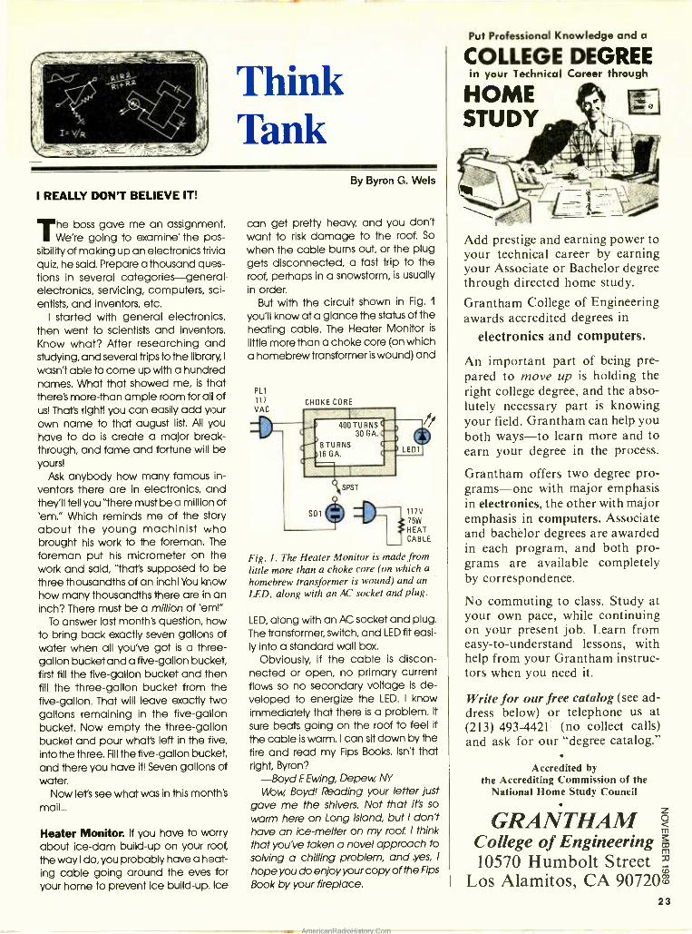
Think Tank
I REALLY DON'T BELIEVE IT!
The boss gave me an assignment. We're going to examine' the pos-
sibility of making up an electronics trivia quiz, he said. Prepare a thousand ques- tions in several categories -general electronics, servicing, computers, sci- entists, and inventors, etc.
I started with general electronics, then went to scientists and inventors. Know what? After researching and studying, and several trips to the library, I
wasn't able to come up with a hundred names. What that showed me, is that there's more -than ample room for all of us! That's right! you can easily add your own name to that august list. All you have to do is create a major break- through, and fame and fortune will be yours!
Ask anybody how many famous in- ventors there are in electronics, and they'll tell you "there must be a million of 'em." Which reminds me of the story about the young machinist who brought his work to the foreman. The
foreman put his micrometer on the work and said, "that's supposed to be three thousandths of an inch! You know how many thousandths there are in an inch? There must be a million of 'em!"
To answer last month's question, how to bring back exactly seven gallons of water when all you've got is a three - gallon bucket and a five -gallon bucket, first fill the five -gallon bucket and then fill the three -gallon bucket from the five -gallon. That will leave exactly Iwo gallons remaining in the five -gallon bucket. Now empty the three -gallon bucket and pour what's left in the five, into the three. Fill the five -gallon bucket, and there you have it! Seven gallons of water.
Now let's see what was in this month's mail...
Heater Monitor. If you have to worry about ice -dam build -up on your roof, the way I do, you probably have a heat- ing cable going around the eves for your home to prevent ice build -up. Ice
By Byron G. Wels
can get pretty heavy, and you don't want to risk damage to the roof. So
when the cable burns out, or the plug gets disconnected, a fast trip to the roof, perhaps in a snowstorm, is usually in order.
But with the circuit shown in Fig. 1
you'll know at a glance the status of the heating cable. The Heater Monitor is
little more than a choke core (on which a homebrew transformer is wound) and
PL1
117 VAC
CHOKE CORE
117V 75W
HEAT CABLE
Fig. I. The Heater Monitor is made from little more than a choke core (on which a homebrew transformer is wound) and an LED, along with an AC socket and plug.
LED, along with an AC socket and plug. The transformer, switch, and LED fit easi- ly into a standard wall box.
Obviously, if the cable is discon- nected or open, no primary current flows so no secondary voltage is de- veloped to energize the LED. I know immediately that there is a problem. It
sure beats going on the roof to feel if
the cable is warm. I can sit down by the fire and read my Fips Books. Isn't that right, Byron?
-Boyd F. Ewing, Depew, NY
Wow Boyd! Reading your letter just gave me the shivers. Not that it's so
warm here on Long Island, but I don't have an ice -melter on my root. I think that you've taken a novel approach to solving a chilling problem, and .yes, I
hope you do enjoy your copy of the Fips
Book by your fireplace.
Put Professional Knowledge and a
COLLEGE DEGREE in your Technical Career through
Add prestige and earning power to your technical career by earning your Associate or Bachelor degree through directed home study.
Grantham College of Engineering awards accredited degrees in
electronics and computers.
An important part of being pre- pared to move up is holding the right college degree, and the abso- lutely necessary part is knowing your field. Grantham can help you both ways to learn more and to earn your degree in the process.
Grantham offers two degree pro- grams -one with major emphasis in electronics, the other with major emphasis in computers. Associate and bachelor degrees are awarded in each program, and both pro- grams are available completely by correspondence.
No commuting to class. Study at your own pace, while continuing on your present job. Learn from easy -to- understand lessons, with help from your Grantham instruc- tors when you need it.
Write for our free catalog (see ad- dress below) or telephone us at (213) 493 -4421 (no collect calls) and ask for our "degree catalog."
Accredited by the Accrediting Commission of the
National Home Study Council
GRANTHAM College of Engineering 10570 Humbolt Street 32
Los Alamitos, CA 90720 23
AmericanRadioHistory.Com
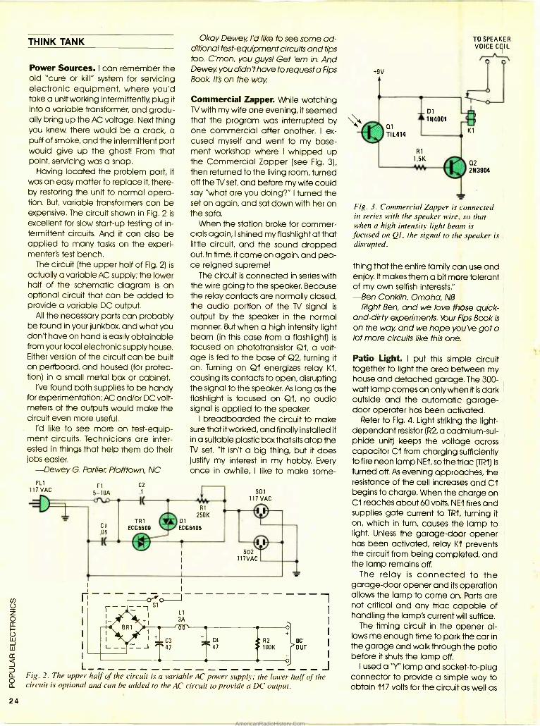
24
THINK TANK
Power Sources. I can remember the old "cure or kill" system for servicing electronic equipment, where you'd take a unit working intermittently, plug it into a variable transformer, and gradu- ally bring up the AC voltage. Next thing you knew, there would be a crack, a puff of smoke, and the intermittent part would give up the ghost! From that point, servicing was a snap.
Having located the problem part, it was an easy matter to replace it, there- by restoring the unit to normal opera- tion. But, variable transformers can be expensive. The circuit shown in Fig. 2 is
excellent for slow start -up testing of in- termittent circuits. And it can also be applied to many tasks on the experi- menter's test bench.
The circuit (the upper half of Fig. 2) is
actually a variable AC supply; the lower half of the schematic diagram is an optional circuit that can be added to provide a variable DC output.
All the necessary parts can probably be found in your junkbox, and what you don't have on hand is easily obtainable from your local electronic supply house. Either version of the circuit can be built on perfboard, and housed (for protec- tion) in a small metal box or cabinet.
I've found both supplies to be handy for experimentation; AC and /or DC volt- meters at the outputs would make the circuit even more useful.
I'd like to see more on test- equip- ment circuits. Technicians are inter- ested in things that help them do their jobs easier.
-Dewey G. Parlier,, Pfafftown, NC PLI FI C2
117 VAC 5 -10A .1
Okay Dewey, I'd like to see some ad- ditional test -equipment circuits and tips too. C'mon, you guys! Get 'em in. And Dewey, you didn't have to request a Fips Book. It's on the way.
Commercial Zapper. While watching TV with my wife one evening, it seemed that the program was interrupted by one commercial after another. I ex- cused myself and went to my base- ment workshop where I whipped up the Commercial Zapper (see Fig. 3), then returned to the living room, turned off the TV set, and before my wife could say "what are you doing ?" I turned the set on again, and sat down with her on the sofa.
When the station broke for commer- cials again, I shined my flashlight at that little circuit, and the sound dropped out. In time, it came on again, and pea- ce reigned supreme!
The circuit is connected in series with the wire going to the speaker. Because the relay contacts are normally closed, the audio portion of the TV signal is
output by the speaker in the normal manner. But when a high intensity light beam (in this case from a flashlight) is
focused on phototransistor Q1, a volt- age is fed to the base of Q2, turning it on. Turning on Q1 energizes relay Kl, causing its contacts to open, disrupting the signal to the speaker. As long as the flashlight is focused on Q1, no audio signal is applied to the speaker.
I breadboarded the circuit to make sure that it worked, and finally installed it in a suitable plastic box that sits atop the TV set. "lt isn't a big thing, but it does justify my interest in my hobby. Every once in awhile, I like to make some-
sol 117 VAC
Fig. 2. The upper half of the circuit is a variable AC power supply; the lower half of the circuit is optional and can be added to the AC circuit to provide a DC output.
+9v
O1
TIL414
_ Dl 1N4001
R1
1.5K
TO SPEAKER VOICE COIL
K1
Q2 2N3904
Fig. 3. Commercial Zapper is connected in series with the speaker wire, so that when a high intensity light beam is focused on Ql, the signal to the speaker is disrupted.
thing that the entire family can use and enjoy. lt makes them a bit more tolerant of my own selfish interests." -Ben Conklin, Omaha, NB
Right Ben, and we love those quick - and -dirty experiments. Your Fips Book is
on the way, and we hope you've got a lot more circuits like this one.
Patio Light. I put this simple circuit together to light the area between my house and detached garage. The 300 - watt lamp comes on only when it is dark outside and the automatic garage - door operater has been activated.
Refer to Fig. 4. Light striking the light - dependant resistor (R2, a cadmium -sul- phide unit) keeps the voltage across capacitor Cl from charging sufficiently to fire neon lamp NE1, so the triac (TR1) is
turned off. As evening approaches, the resistance of the cell increases and Cl begins to charge. When the charge on Cl reaches about 60 volts, NE1 fires and supplies gate current to TR1, turning it on, which in turn, causes the lamp to light. Unless the garage -door opener has been activated, relay K1 prevents the circuit from being completed, and the lamp remains off.
The relay is connected to the garage -door opener and its operation allows the lamp to come on. Parts are not critical and any triac capable of handling the lamp's current will suffice.
The timing circuit in the opener al- lows me enough time to park the car in the garage and walk through the patio before it shuts the lamp off.
I used a "Y" lamp and socket -to -plug connector to provide a simple way to obtain 117 volts for the circuit as well as
AmericanRadioHistory.Com
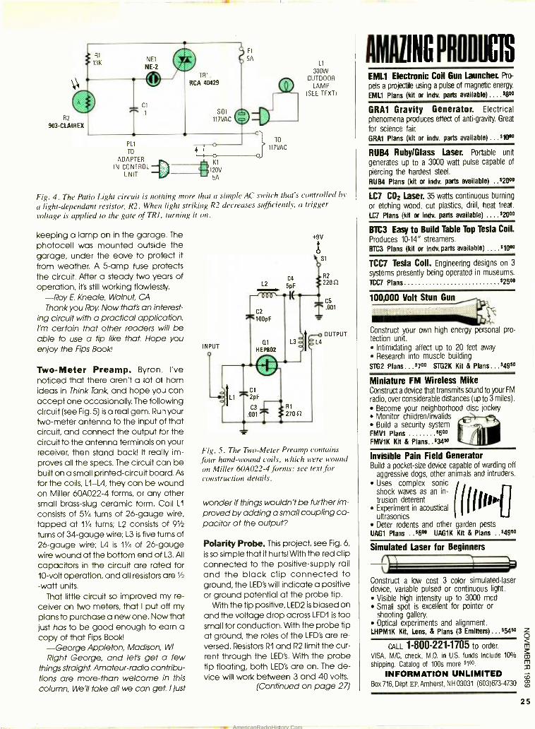
NEI NE -2
Fl
5A
RCA 40429
R2
903-CLAIREX 117VAC
PLI
TO o ADAPTER
K1 IN CONTROL 4-1120V
UNIT 5A
TO
117VAC
Ll 300W
OUTDOOR LAMP
(SEE TEXT)
Fig. 4. The Patio Light circuit is nothing more that a simple AC switch that's controlled by
a light- dependant resistor, R2. When light striking R2 decreases sufficiently, a trigger voltage is applied to the gate of TRI, turning it on.
keeping a lamp on in the garage. The photocell was mounted outside the garage, under the eave to protect it
from weather. A 5 -amp fuse protects the circuit. After a steady two years of operation, it's still working flawlessly.
-Roy E. Kneale, Walnut, CA Thank you Roy. Now that's an interest-
ing circuit with a practical application. I'm certain that other readers will be able to use a tip like that. Hope you enjoy the Fips Book.
Two -Meter Preamp. Byron, I've noticed that there aren't a lot of ham ideas in Think Tank, and hope you can accept one occasionally. The following circuit (see Fig. 5) is a real gem. Ru -1 your two -meter antenna to the input of that circuit, and connect the output for the circuit to the antenna terminals on your receiver, then stand back! It really im- proves all the specs. The circuit can be built on a small printed- circuit board. As
for the coils, L1 L4, they can be wound on Miller 60A022 -4 forms, or any other small brass -slug ceramic form. Coil L1
consists of 51/4 turns of 26 -gauge wire, tapped at I1/4 turns; L2 consists of 91/2
turns of 34 -gauge wire; L3 is five turns of 26 -gauge wire; L4 is 1 °/4 of 26 -gauge wire wound at the bottom end of L3. All
capacitors in the circuit are rated for 10 -volt operation, and all resistors are 1/2
-watt units. That little circuit so improved my re-
ceiver on two meters, that I put off my plans to purchase a new one. Now that just has to be good enough to earn a copy of that Fips Book!
-George Appleton, Madison, WI
Right George, and let's get a few things straight. Amateur -radio contribu- tions are more -than welcome in this
column, We'll take all we can get. I just
INPUT
+9V
sl
R2
220E2
C5 .001
OUTPUT L4
Fig. 5. The Two -Meter Preamp contains four hand -wound coils, which were wound on Miller 60A022 -4 forms; see text for construction details.
wonder if things wouldn't be further im- proved by adding a small coupling ca- pacitor at the output?
Polarity Probe. This project, see Fig. 6,
is so simple that it hurts! With the red clip connected to the positive -supply rail and the black clip connected to ground, the LED's will indicate a positive or ground potential at the probe tip.
With the tip positive, LED2 is biased on and the voltage drop across LEDI is too small for conduction. With the probe tip at ground, the roles of the LED's are re- versed. Resistors R1 and R2 limit the cur- rent through the LED's. With the probe tip floating, both LED's are on. The de- vice will work between 3 and 40 volts.
(Continued on page 27)
MPJING P000UCIS EML1 Electronic Coil Gun launches Pro-
pels a projectile using a pulse of magnetic energy.
EML1 Plans (kit or indv. parts available) .... $800
GRA1 Gravity Generator. Electrical phenomena produces effect of anti -gravity. Great
for science fair.
GRA1 Plans (kit or indv. parts available) $1000
RUM Ruby /Glass Laser. Portable unit
generates up to a 3000 watt pulse capable of
piercing the hardest steel.
RUM Plans (kit or indv. parts available) $2000
LC7 CO2 Laser. 35 watts continuous burning
or etching wood, cut plastics, drill, heat treat.
L.C7 Plans (kit or indv. parts available) salmi lmi
BTC3 Easy to Build Table Top Tesla Coil. Produces 10 -14" streamers. BTC3 Plans (kit or indv.parts available) $1000
TCC7 Tesla Coil. Engineering designs on 3
systems presently being operated in museums.
TM Plans $2500
100,000 Volt Stun Gun
Construct your own high energy personal pro- tection unit.
Intimidating affect up to 20 feet away Research into muscle building
STG2 Plans...5700 STG2K Kit & Plans ...$4955
Miniature FM Wireless Mike Construct a device that transmits sound to your FM
radio, over considerable distances (up to 3 miles).
Become your neighborhood disc jockey Monitor children /invalids Build a security system
FMV1 Plans $600
FMV1K Kit & Plans $3450
Invisible Pain Field Generator Build a pocket -size device capable of warding off
aggressive dogs, other animals and intruders.
Uses complex sonic shock waves as an in-
trusion deterent Experiment in acoustical ultrasonics Deter rodents and other garden pests
UAG1 Plans ..$600 UAG1K Kit & Plans ..$4950
((i'iu.#J
Simulated Laser for Beginners
Construct a low cost 3 color simulated -laser device, variable pulsed or continuous light.
Visible high intensity up to 3000 mcd Small spot is excellent for pointer or shooting gallery. Optical experiments and alignment.
LHPM1K Kit, Lens, & Plans (3 Emitters) ... $5450
CALL 1- 800 -221 -1705 to order.
VISA, M/C, check, M.O. in U.S. funds Include 10%
shipping. Catalog of 100s more s100.
INFORMATION UNLIMITED Box 716, Dept.EP, Amherst, NH 03031 (603)673 -4730
25
AmericanRadioHistory.Com
26
22 Reasons Why TAB Is Your Source for Electronics Books
Computer Technician's Handbook -3rd Ed. by A. Margolis. Repair compo- nents and systems, perform routine main- tenance, and diagnose defective equipment with this completely revised edition of the popular bestseller on microcomputers. Get the edge you need with the latest technolog- ical advancements, including RAMS; 80286, 80386, Z8001- Z8002, and 32 -bit processors; chip replacement; and soldering techniques with new surface mounted devices. 590 pp., 409 illus.
#3279H, $34.95
Save $10 on the Set Pass the Associate and journeyman
Exams with Flying Colors! The CET Exam Book -2nd Ed. by R. Crow and D. Glass. 226 pp., 211 illus.
The CET Study Guide -2nd Ed. by S. Wilson. 336 pp., 179 illus.
Two Volume Set ( #5300C) Yours for $35.90 (Regularly $45.90)
Enjoy Building These Fun Projects And Save 15%
49 Battery- Powered One -IC Projects by D. T. Horn. 168 pp., 153 illus.
49 Battery- Powered Two -IC Projects by D. T. Horn. 126 pp., 125 illus.
Two Volume Set ( #5381C) -Yours for $31.95! (Regularly $37.90)
L:13 --RSZ.::.
"This book is outstanding ... All of the circuits use the latest in state -of- the -art technology and may be used in the home or industry ... you should have a lot of fun with this fine book. -The Electron Encyclopedia of Electronic Circuits -Vol. 2 by R. Graf. 700+ circuits you'll use again and again including automotive circuits ... clock circuits ... gas and smoke detectors ... sine -wave oscillators ... and more. 744 pp., 728 illus. #3138H, $39.95 (Regularly $60.00)
Build Your Own 80386 IBM® Compatible and Save a Bundle by A. Pilgrim. Get power and efficien- cy at a down -to -earth price! 232 pp., 84 illus. #3131H, $24.95
Troubleshooting and Repairing the New Per- sonal Computers by A. Margolis. Save hundreds of dollars in repair costs! 416 pp., 350 illus. #2809H, $27.95
The Master Handbook of IC Circuits -2nd Ed. by D. Horn. Build over 950 different circuits using 200 + popular ICs! 544 pp., 960 illus. #3185H, $34.95
The 8088 Project Book by R. Grossblatt. Design and construct an 8088 computer and 17 hardware and software enhancements! 256 pp., 125 illus. #3171H, $27.95
Troubleshooting and Repairing VCRs by G. McComb. Save money making your own VCR repairs! 336 pp., 200 illus. #2960H, $27.95
Build Your Own Universal Interface by B. Chubb. Use your computer to control almost any- thing! 285 pp., 224 illus. #3122H, $27.95
Customize Your Home Entertainment System by S. Sokolowski. Build audio and video enhancements with 22 inexpensive projects! 288 pp., 100 illus. #3234H, $24.95
The Laser Cookbook by G. McComb. 88 inexpen- sive, fun -filled and useful projects! 401 pp., 361 illus. #3090H, $25.95
The Illustrated Home Electronics Fix -It Book -2nd Ed. by H.L. Davidson. Save yourself time, aggravation, and money with fix -it- yourself how -to! 432 pp., 377 illus. #2883P, $16.95
Practical Transformer Design Handbook -2nd Ed. by E. Lowdon. Build power, impedance, and current transformers for all your needs! 400 pp., 288 illus. #3212H, $34.95
General Radiotelephone Operator's License Study Guide -2nd Ed. by T. LeBlanc, NX7P. Get the edge you need to pass this important test! 259 pp., 125 illus. #3118H, $23.95
Save $ 50 on the TAB Hobby Electronic Series The Five -Volume Set ( #5282C) -Yours For Just $51.378 (Regularly $104.75)
Basic Electronics Course -2nd Ed. by N. Crowhurst. Master the fundamentals, prepare for the future! 400 pp., 347 illus. #2613H, $24.95
How to Read Electronic Circuit Diagrams -2nd Ed. by R. Brown, P. Lawrence, and J. Whitson. Become proficient in the "language" of circuitry! 224 pp., 213 illus. #2880H, $20.95
How to Test Almost Everything Electronic -2nd Ed. by J. Darr and D. Horn. A must -have bestseller, over 35,000 copies sold! 180 pp., 138 illus. #2925H, $16.95
44 Power Supplies for Your Electronics Projects by R. Traister and J. Mayo. Simple or advanced circuits for all your project designs! 220 pp., 208 illus. #2922H, $24.95
Beyond the Transistor: 133 Electronics Projects by R. Turner and B. Rutherford. Make the most of semiconductors -no experience necessary! 240 pp., 173 illus. #2887H, $16.95
TO ORDER, CALL TOLL FREE: 1- 800 -822 -8158
(in PA and AK call direct 1- 717- 794 -2191) or detach and mail coupon to:
TAB BOOKS Inc., Blue Ridge Summit, PA 17294 -0840 Please send me the book(s) below.
N Price
H Price
# Price
Price C Check or money order enclosed (made payable to TAB BOOKS Inc.)
In PA, NY, and ME add applicable sales tax. (Outside the U.S. add $5.00 for shipping and handling.)
Charge my Cl VISA L' MasterCard L American Express
Acct. No. Exp
Signature
Name
Address
City
State /Zip Prices subject to change.
Satisfaction Guaranteed -If you are not satisfied, return the books for a complete refund. PE119
CIRCLE 20 ON FREE INFORMATION CARD
AmericanRadioHistory.Com
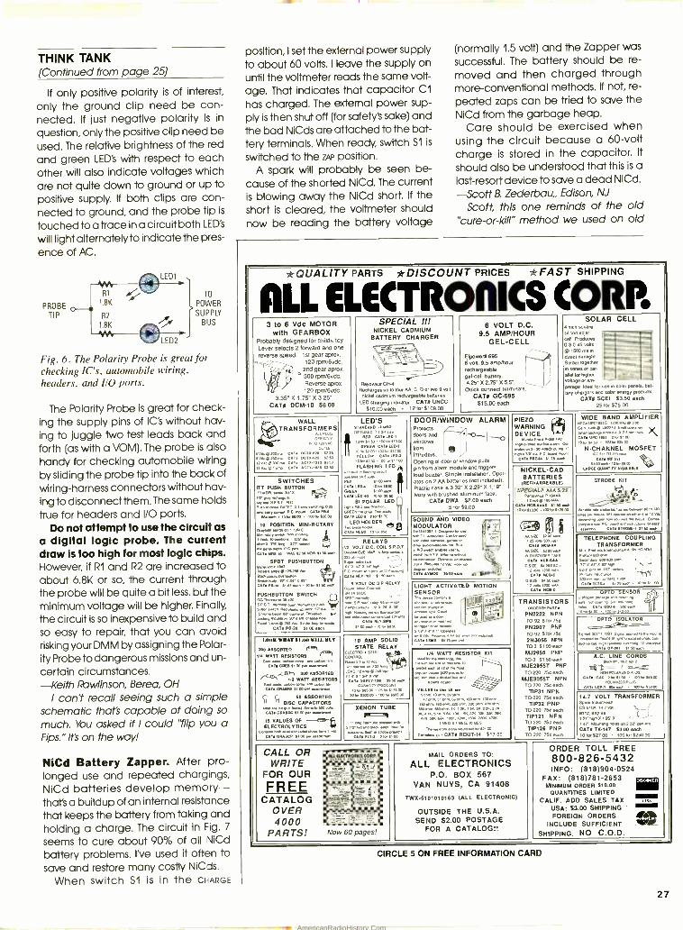
THINK TANK (Continued from page 25)
If only positive polarity is of interest,
only the ground clip need be con- nected. If just negative polarity is in
question, only the positive clip need be used. The relative brightness of the red
and green LED's with respect to each other will also indicate voltages which are not quite down to ground or up to positive supply. If both clips are con- nected to ground, and the probe tip is
touched to a trace in a circuit both LED's
will light alternately to indicate the pres-
ence of AC.
PROBE
TIP R2
1.8K
TO
POWER
SUPPLY BUS
Fig. 6. The Polarity Probe is great for checking IC's, automobile wiring, headers, and I/O ports.
The Polarity Probe is great for check- ing the supply pins of IC's without hav-
ing to juggle two test leads back and forth (as with a VOM). The probe is also handy for checking automobile wiring by sliding the probe tip into the back of wiring -harness connectors without hav-
ing to disconnect them. The same holds
true for headers and I/O ports. Do not attempt to use the circuit as
a digital logic probe. The current draw is too high for most logic chips. However, if R1 and R2 are increased to about 6.8K or so, the current through the probe will be quite a bit less, but the minimum voltage will be higher. Finally,
the circuit is so inexpensive to build and so easy to repair, that you can avoid risking your DMM by assigning the Polar-
ity Probe to dangerous missions and un-
certain circumstances. -Keith Rawlinson, Berea, OH
I can't recall seeing such a simple schematic That's capable of doing so
much. You asked if I could "flip you a Fips. "It's on the way.!
NiCd Battery Zapper. After pro- longed use and repeated chargings, NiCd batteries develop memory - that's a buildup of an internal resistance that keeps the battery from taking and holding a charge. The circuit in Fig. 7
seems to cure about 90% of all NiCd
battery problems. I've used it often to
save and restore many costly NiCds.
When switch S1 is in the CHARGE
position, I set the external power supply to about 60 volts. I leave the supply on until the voltmeter reads the same volt- age. That indicates that capacitor C1
has charged. The external power sup- ply is then shut off (for safety's sake) and the bad NiCds are attached to the bat- tery terminals. When ready, switch S1 is
switched to the ZAP position. A spark will probably be seen be-
cause of the shorted NiCd. The current is blowing away the NiCd short. If the short is cleared, the voltmeter should now be reading the battery voltage
(normally 1.5 volt) and the Zapper was
successful. The battery should be re-
moved and then charged through more -conventional methods. If not, re-
peated zaps can be tried to save the NiCd from the garbage heap.
Care should be exercised when using the circuit because a 60 -volt charge is stored in the capacitor. It
should also be understood that this is a last- resort device to save a dead NiCd.
-Scott B. Zederbau Edison, NJ
Scott, this one reminds of the old "cure -or- kill" method we used on old
*QUALITY PARTS *DISCOUNT PRICES *FAST SHIPPING
ALL ELECTRORICS CORR 3 to 6 Vdc MOTOR
with GEARBOX Probably designed for chikJs toy. Lever selects 2 forward and one reverse 1st ears s', Speed. g M - 120 rpnV6vdc,
2nd
SPECIAL I!! NICKEL CADMIUM
BATTERY CHARGER
Ç - Reyovace CH -4
Recharges up to four AA. C, D or two 9 volt
nickel cadmium rechargeable bananas.
charging LED char dn, r CATB UNCC $10.00 each 12 for 5108.00
6 VOLT D.C. 9.5 AL -CELLR
GEL -CELL
SOLAR CELL SOLAR square
silicon solar CAll. Prague. 0 3-0 45 volts @1500 ma in
Greet sunlight Idler together n seems 0r per. anal br higher
9.595 6 volt, 9.5 ampRwur rechargeable gel-cell battery.
Y l
_= E.
_ gear aprox. ` 300
Reverse Reverse aprox. 120 rprw6vdc.
CATS DCM -10 56.00 3TS X 1.75 - X
4.25- X 2.75' X 5.5'. ` Oulck connect terminals
CAT* GC -695 $15.00 each
voltage or am-
pe'a9e Ideal for use in solar panels, bat
rely chargers and solar energy products
CATI SCEL 53.50 each 25 for $75.00
WALL TRANSFORMERS
ALL PLUG Z..
ronWC
vm2mma CAT. n<m IS
vKu CAT ACTL.25 Ku {m.. c x n. AC
', v.. ''90 CATS Acnn.es taco
LED's JUDDO
asap ° LEO2
pub CAT; 1 ,osn.00 YELLOw.100T LED.,
,w 42.00 ,00I-SI200 ,0
FLASHING LED p1 nor w
DOOR /WINDOW
doors and f' windows
Protects
form intruders. L opening of door or
ALARM - -O ISO
JI
/ window Pulls
PIEZO WARNING DEVICE
En.PKm -.A0
mwd ww.Nw, ew sm'w. I. ,s"r'r Oa PC mwr '
CATS.u« SI75 nor
WIDE BAND AMPLIFIER WIDE NEON ,CM.. IMO Mn 3.N y
AMPLIFIER
^iOi' -"i" xm '"°- '\ cT ux.hu, bM s° , -S35m ro
N- CHANNEL MOSFET wv.sn TOM..
CATIRE SP Sim wen SOUK 10.00
WIDE QUA1mTYVwWKE pin from alarm module and triggers
bud buzzer. Simple installation. Opel-
ales on2AA bananas X Plastic case is 3.d2' 2.29- X
face. Ivory with brushed aluminum lace.
CATS DWA 62.00 each 5 for $9.00
NICKEL -CAD BATTERIES
(RECHARGEABLE) SWITCHES
ITT e0PLU3SH BUTTON
ID, ap'sys NO f
-n map.. DATED 0.1 °P.- ,mve.OW ...Try pup. G. no... CAT. PH
SS. own 10.10.00 ,m -$50.00
TO POSITION MINI- ROTARY Ora nRP >a ,,w°
Pub.. Lisw
Wu.... e.n.a
CAW n POP. cr. .e
PUSHBUTTON
NOW fl 50 AO
SPOT PUSHBUTTON L BM' o1' ' :',V
-. ed.
CAT. LO SI AO n n,. SI SO .a ' ary a.Ha
PUSHBUTTON SWITCH 0.71....3.5.420
pun s :.. R.N , K Has ..
44
°l.ÿ,,0_.'000000`00... 1T R 50.00" N
each
mpe. CAT. Pazo s,roe.m
CADw.D f,m.w C"'-"- ,°,a. Sam
CAW WUa 0 b go.
m
Lg. WO o.00:ó. BIPOLAR
GREEN ,Mm... L.o* TLEU 2lo SIm CATS
HOLDER 00 a PLED
STROBE KIT
SPECIALII AAA SIZE
12.d,.puu T. NoLA00,,o. ..n
101 Sam í,25.m
D
m SO Vn.u..w Wolu 10.1.1.... '12Vá
SOUND AND VIDEO
U141301 -1 lore MODULATOR ®
AT.LNO.í. AA SIEE 5220. 04
WITH SOLOED TABS
AT -f CS S. n EACH
CAT no.0
no....mou n.oguabenu.SofCO -.mw..e PC baud w."imood Cm
-wmY C22STRDBE..f7mown CA 10I -AL r
.. , ..°.a e.m d.7°ß. (.
SRN" ..." C_N
°iM°9" OP.-.. 0.0..p. !` -. O.K. Vse.,m90 I I l
CTVYpD ümuen - CCii
TELEPHONE COUPLING TRANSFORMER
ewi Products ro, w sm a° m
, 2"'° ! 1_ (' b 300
r ' ° ry ttT%n' f, Y+..c' ,
RELAYS VOLT D.a cos. S.P.O.T.
MS W D2E.,..P . AI-
m.... -t ' ~ C rmunl IRO* on OM
CATS PLY77 O SO sacn'p 5 VOLT DC SIP RELAY
SR IA SVOC
,,,PTSPr w, PM 003
-.v., thaws.. ***OR - an'OV" 1'00..el ,O,o SBA
LIGHT ACTIVATED MOTION SENSOR
oseE K. IMO IT
°''T MCSO OPTO SENSOR
o 14. n" I- n C 50 '
a ....»
.ws iyn, c: °> tear..,
101,, osw OO
QBVI
0 :1-
o °o T I ] Lys
TRANSISTORS oRaERe PRT.
PN2222 NPN T0925t00750 PN2907 PNP TO-92 5ó75C 2N3055 NPN TO-3 f1 CO Sad, M,$2955 PNP TO-3 51.50 each
MJE2955T PNP TO-220 750 each
MJE3055T NPN 700220 75c each
TIP31 NPN TO-220 754 each
TIP32 PNP Tan° 750 ee<I,
TIP121 NPN TO-220 75s each
T P126 PNP 70220 754 each
OPTO ISOLATOR
Se. 33171.1201 Sew N0a10 ,nwn LuMa,N^.NNp'Ienm.m+.amNpmp-
04°"°"'`;áúÓ30N; ¡50.c. tl°" UteH WHAT 111.00 WILL BUY
200 ASSORTED /'..1 /®1 ,/4 WA RESISTORS
CAW OM S,mw...pn1p.'Nm em,
.CSL11 200 ASSORTED - hR WATT RESISTORS
CMiliuAwEf CO
,. ( f SO ASSORTED Il Tl DISC CAPACITORS
Hoe a ro.c NHal Sanwa 500 .x. CATS GNAW S, CO RN/ Hammes
15 VALUES OF -ii Fi EL" "'.- -LYTICS j
w .ono CAT. °NAACP S1.m i
10 AMP SOLID STATE RELAY
LECmou WW1
q'o VW an pwlwm532 van\/fP LOA°. oulo2.o V-
'OATI550LVTO ° A ., a S050.4. OWNO7VD/SCOWT
p,- óS00 25.1175.00
501 u0040 KO tor X00'00
A.......° ' Haws` CAT4 MID S5 7sm +p
//4 WATT RESISTOR KR .-A.n- I..
a2dt osl P w ..0 ,00o. -I° ,N Inc.. aKK.a m..na P,. _
,wN -s0,. _ . VALUES M II. AN
e3 wnado Onm ss ohs.,oPnm. Lwpmn,N ,ac',x2N :xK x,K
m5'hK 5SPC,al ISK, K.:K....K. ' EO. S' 0.10 uEo '
.n-. Cann - An CATS REKIT -/4 517.00
A.C. cLINE vCORDS ,,p- / e,;11,"
ran rtRARosostuD CATELWC 2,90 5, 00 100óM500
wLARon1p c7 ... hm -Isom LDP.' m
14.7 VOLT TRANSFORMER Sons. mown*. cSS,a ,.7 vwl.
CO h. Set v `l ,.2.,, x,95% ,Lr Wunurp eoanw. CATS TK -147 f3 00 each 101°,5E7 03 00 for f25000
XENON TUBE P{c ,1 bne Panty. 0,09000 c111
*crone 1.11 or Wan pom. CATO ELT.3 2,0,Vá0
CALL OR WRITE
FOR OUR
FREE
-4' rc ' _ ; -_ r
_ ', A °}
MAIL ORDERS TO:
ALL ELECTRONICS P.O. BOX 567
VAN NUYS, CA 91408
TWX- 61 01 01 01 6 3 (ALL ELECTRONIC)
OUTSIDE THE U.S.A. SEND 52.00 POSTAGE
ORDER TOLL FREE 800 -826 -5432 INFO: (818)904-0524
FAX: (616)761 -2653 MINIMUM ORDER $10.00
xww
QUANTITIES LIMITED
CATALOG OVER 4000
CALIF. ADD SALES TAX t® ,ffl - - -
a
USA: $3.00 SHIPPING '
DE E INCLUDE SUFFICIENT
PARTS! Now 60 pages! FOR A CATALOG!! SHIPPING. NO C.O.D.
CIRCLE 5 ON FREE INFORMATION CARD
27
AmericanRadioHistory.Com
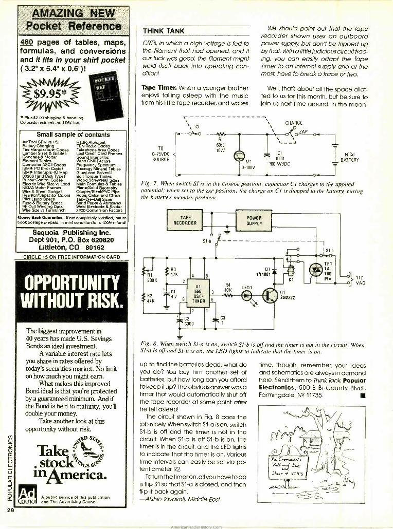
i M / / M /
480 pages of tables, maps, formulas, and conversions and it fits in your shirt pocket ( 3.2" x 5.4" x 0.6 ")!
REF
$9.95*
* Plus $2.00 shipping & handling. Colorado residents add 560 tax.
Small sample of contents Air Tool CFM vs PSI Radio Alphabet Battery Charging TEN Radio Codes Tire Manufacturer Codes Telephone Area Codes Lumber Sizes & Grades Lost Credit Card Phones Concrete & Mortar Sound Intensities Element Tables Wind Chill Factors Computer ASCII Codes Frequency Spectrum IBM* PC Error Codes Geology Mineral Tables IBM* Interrupts-I0 Map Glues and Solvents 80286 Hard Disk Types Bolt Torque Tables Printer Control Codes Wood Screw/Nail Sizes Electric Wire Size vs Load Math Formulas & Tables NEMA Motor Frames Plane /Solid Geometry Wire & Sheet Guages Copper /Steel/PVC Pipe Resistor /Capacitor Colors Rope Cable and Chain Pilot Lamp Specs Tap- Die-Drill Sizes Fuse & Battery Specs Send Paper & Abrasives RF Coll Winding Data Weld Electrode & Solder Wire Size vs Tums/Inch 3200 Conversion Factors
Money Back Guarantee- If not completely satisfied, return book postage prepaid, in mint condition for a 100% refund!
Sequoia Publishing Inc. Dept 901, P.O. Box 620820
Littleton, CO 80162 CIRCLE 15 ON FREE INFORMATION CARD
OPPORTUNITY WITHOUT RISK.
The biggest improvement in 40 years has made U.S. Savings Bonds an ideal investment.
A variable interest rate lets you share in rates offered by today's securities market. No limit on how much you might earn.
What makes this improved Bond ideal is that you're protected by a guaranteed minimum. And if the Bond is held to maturity, you'll double your money.
Take another look at this opportunity without risk.
Take a stockGse0
inAmerica. A public service of this publication
&1CI and The Advertising Council.
28
THINK TANK
CRT's, in which a high voltage is fed to the filament that had opened, and if our luck was good, the filament might weld itself back into operating con- dition!
Tape Timer. When a younger brother enjoys falling asleep with the music from his little tape recorder, and wakes
TO
0 -75VDC SOURCE
We should point out that the tape recorder shown uses an outboard power supply, but don't be tripped up by that. With a little judicious circuit trac- ing, you can easily adapt the Tape Timer to an internal supply and at the most, have to break a trace or Iwo.
Well, that's about all the space allot- ted to us for this month, but be sure to join us next time around. In the mean-
CHARGE o
ZAP o. Rl N,`--
6012
lOW
©Ml 0-100V
+ Cl
T 1000
100-WVDC
1 NiCd
! BATTERY
T
Fig. 7. When switch SI is in the CHARGE position, capacitor CI charges to the applied potential; when set to the ZAP position, the charge on CI is dumped to the battery, curing the battery's memory problem.
Fig. 8. When switch SI -a is on, switch SI -b is off and the timer is not in the circuit. When SI -a is off and Sl-b is on, the LED lights to indicate that the timer is on.
up to find the batteries dead, what do you do? You buy him another set of batteries, but how long can you afford to keep it up? The obvious answer was a timer that would automatically shut off the tape recorder at some point after he fell asleep!
The circuit shown in Fig. 8 does the job nicely. When switch Sl -a is on, switch S1 -b is off and the timer is not in the circuit. When S1 -a is off S1 -b is on, the timer is in the circuit. and the LED lights to indicate that the timer is on. Various time intervals can easily be set via po- tentiometer R2.
To turn the timer on, all you have to do is flip S1 so that Sl-a is closed, and then flip it back again. -Afshin Tavakoli, Middle East
time, though, remember, your ideas and schematics are always in demand here. Send them to Think Tank, Popular Electronics, 500 -B Bi- County Blvd., Farmingdale, NY 11735.
AmericanRadioHistory.Com
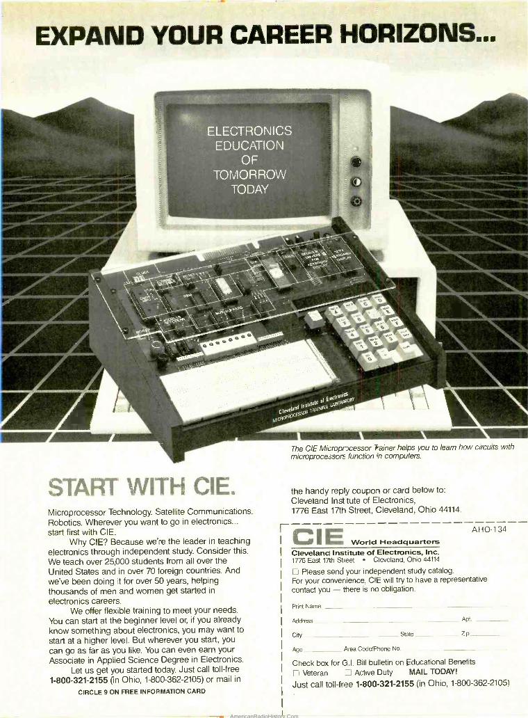
EXPAND YOUR CAREER HORIZONS...
ELECTRONICS EDUCATION
OF TOMORROW
TODAY
ca5A.* É ; ï
6,'..
START WITH CIE. Microprocessor Technology. Satellite Communications. Robotics. Wherever you want to go in electronics... start first with CIE.
Why CIE? Because we're the leader in teaching electronics through independent study. Consider this.
We teach over 25,000 students from all over the United States and in over 70 toreign countries. And we've been doing it for over 50 years, helping thousands of men and women get started in
electronics careers. We offer flexible training to meet your needs.
You can start at the beginner level or, if you already know something about electronics, you may want to
start at a higher level. But wherever you start, you
can go as far as you like. You can even earn your Associate in Applied Science Degree in Electronics.
Let us get you started today. Just call toll -free
1- 800 -321 -2155 (in Ohio, 1 -800- 362 -2105) or mail in
CIRCLE 9 ON FREE INFORMATION CARD
The CIE Micropr cessor Trainer helps you to learn how circuits with microprocessors function in computers.
the handy reply coupon or card below to:
Cleveland Institute of Electronics, 1776 East 17th Street, Cleveland, Ohio 44114.
C I E World Headquarters Cleveland Institute of Electronics, Inc. 1776 East 17th Street Cleveland, Ohio 44114
C Please send your independent study catalog. For your convenience, CIE will try to have a representative contact you - there is no obligation.
AHO-134
Print Name -
Address Apt,
City State - Zip
Age Area Code/Phone No.
Check box for G.I. Bill bulletin on Educational Benefits
Veteran `: Active Duty MAIL TODAY!
Just call toll -free 1- 800 -321 -2155 (in Ohio, 1- 800 -362 -2105)
AmericanRadioHistory.Com
32
/EjiaNt, C O R P O R A T I O N
1- 800 -344 -4539 AK, Puerto Rico - 218 -681 -6674 Telex - 62827914 FAX - 218-001 -3350 TN/ X - 9103508982 DIGI KEY CORD
INTEGRATED CIRCUITS
)1an TTt
74405
79516
7.51 70041 4736
410101
74.02
F1":.73114 1002
741704 E!
741 90
iijgÑ 11
NILH I.W
7.102 65 7,43076
74LM0 TEL
M
7457.
FiE ram
u 4MCMOS 7457406 63 AAA
22.223 .1001
1: macs .0101
.211109 403.7602 55 407-7009
0017806 402011.2 .0091 40.6 .16 403.06 4036906
4042609 .3809 404411.
4042619 404011.
050619
06.49 9363609 .06179
CMOS
40104
40103.4
401.091
AA. AAA
NC. 46 4034N 26
7.1414 40.0 4020 417 .424 I
6C400 1 32 MC77. 66
_
.199
*Me
7M 4.002
0:9411 1 701004
461009 017. O 0.
4577609 C19. 0.609 1cv1x .109
.77314 2 23 0774005
LYWr 0913. L5 ou AA.
09769 6 25 7,23479 T 20
401 401ä 1.431.
N11C
.9104
.9220
.5261 40.311 40.4
02191 01120
40.70 400960
600.1 117.10 7
MON
1.9 CMOS
1.094 20 721110.
14.1
700775
700 739 74.7402 791054 741.7511
74.11.
14.1260
IW4158
7.0694
/0.1960
36 2, 202.2,022
70.2610
1404..0 33
69
12300
0.433. 9230.2 540,
91.1774 1037144
140.
443.40.
.11
90144
9101900
943014 40 ir 127920
543050 10161
271.1.
.3602 1456414 166521
INTEGRATED CIRCUITS
'227 2 MA 2 16
0290. 20 MINN 20
6129:612 3 90 11.07N 110
1129074 0 2 70 M76170 273
0623175 0 03 909317 50 . 1120.11C1 1 29 0.664 1 36 2430042 26 .1160 64 0.022
.1329 91.319 1 02 0155702 3 IS 11MM 93 01090 /
WON I 50 11406110 72S 9430104 26 039156 54291. 205
7232223 2 40111.15/C2 54
1915C 96
1211110CC4 5:
11700? 75
16
WO 76
NM 43
1.00
AN 21 0602
22322
1.74
90121104 3. 00
:49999 19
74.76 7 00
7.47502 4 00 3 75
0p40. s
01061. s
001. 79224.
002. 017.9
MOW 2
03109
667302 11 5. 5100114 17
I 113 762 25 CO
1015.12..
A/D S D/A
S11Mep M A.
7.024
15491 15010
SRR'0. M TMwgiplS
.30
709
2114.6.
704402
Tg
10 9.2
Ig
a tm
12
2.1 230 1840
17.2
10 92 31
2232 P4
1019 260 TO 9.7
E 31
70 39 37
1,0
10 39
222
4,2
3232
70 02 a
gg
21
24
27
10
on
00 00
9,60 6150
SILICON TRANSISTORS
1.7503
12114274
10 92
1223
3823 2 TO 92 26
ig: 96 01
2 12 2 72
3g332 ;2; TO PO
6 03
10 270 3322 ;
220 .81
TO 220
10 DO
/OM In
10 220 4'
2222 ;21
10 T. 144
1 AMP SILICON RECTIFIERS
1'/e METAL OXIDE FILM RESISTORS
Pa m
NO
1460
911.76 5. Jose ir 70110 se 700
TRANSFORMERS 0.02 1.2.111551
5.0 10 .141 N Vtw 1Tr..no.0.m
evw VRBru _ _VA
oBaw 5000 7701-613 I.eBZO e.a07m
258225 ae® 12m.91220e0
150445
ÑIä iié 40 110 mBm r0lION eB2ao
4.4 10
3eBBaN e.]BIW meerm pBleR a15P 11*m HBem I28555
mlem mBaP 581en 1BBm00 e.sBSSm N 15.79
Trilg s ® XiO 11 ® Iso xlelmS
u1288 aBeP 1en aI 8 m0 12 Vt..] 11 P1 15leP aB1225 a 15.22
C29.11. h.. 11257127
5% CARBON FILM RESISTORS
PANASONIC LS SERIES
100
7000 2700
4700 9 71 232
16 158 13 56 03 00 1
25 21
51
7S 35 25 46 03
220 25 62 31 330 25 73
g9 Z i3 3030 25 2 20 7 04 157 00 2 9 59
470 ea 7 53 62 75 SI 1 WOO 05 134 11 46 9.0 176 IC. MO 35 220 NIP 157 00 2 29 19 APO 76 7 71 23 75 193 75
1/2 Wa0 e.._. 50 21 T 83
IR
6% WIREWOUNO REC. RESISTORS
5 Wen 110.
TOG 0021.
om n /S!
96 L eá10 ems
5 °., METAL OXIDE FILM RESISTORS
I.5Kw11w aMO 1 wml. t1w. m.Oy.IC pnl'.I 103120_. - I e IN rN :1_,M
TI N 1110 A 0 15.m
40 00 7250 lb 20 9
47,0111_7_ m I.M 13 15 U.W IW.tl
ot. P-i0 Y.ue.Wmr
NAS1nu
n Ml IRA
1-mmNV 901 5 each of .15440526 to 7 NM RTIO
total .4010 x102.10 _1NmnWx+.l.l1[aw1Ap
.. 1
nr-
5Yw1 A_R. _ ç
IMO .21erolw 0t
63 10 One 000 106
.2n 19 14 15950 2 29 1
470
Rom
74026
01006 8.03
111140
141
DISC CAPACITORS
AO 1CO2 p1
1500 of DOD of
4700 093
110,
.03 pt Ñ
03.0 pi
RISC CAPACITORS
6600 pi 1K 8 0 67,50 517 SR
RAI A
3300 pl 4700 of Rao 91
1.0 of 15050 pl
4103 1.0
330 p1 .4107 HO pl
660 01 070 of
Ff o
130 pf
500 01
pf 070 01 7
1500 9 11160 421
7100 01 2700 of 330010
3000 61
61 WOOD 0 SO IX 6 90
b ¿r 60
H am
93 23 40
3.1
>m W 71 131 41:
4703
1me1 100
.000 25 75 6 00 46 00
N05 p 22000 0 25 0
.300, IS
'.4.441 47003 pf 1: 127 It Itt!
2260 10
War
4404
007 31: 4.109
47 0
"1 921
03 40
20 CO
30 24. 22
pIW-n.y eg. YM. Nb im
"23 gn .2
10 6 3 42 3.64 3130 IS 50 4 34
66' t46 23 22
i9 1 02 Ts. 136 SO
I 10 10 30 06 50
100 31 41 200 10 0011 90
2 7 10 87.30
85 7 40 63 93
220
1 2 70 20 10
PAN
0222 0 92020
172072 003 97074 .075 177076 0077 92078 7104
ar lmlÓ
I 1 19 10410
"20 10 27 215 20 10 27 20 10
27
YO
25 00
16 45 141.
.50 36 11.0 1002 00 26 2 46
0 50 2 59 2100 00
I 41 19 029'
11.1 9: 25250
PANASONIC V SERIES
Peons
I/O. Dog. Key volume 2.7600 ä1d service r:11ä1ge5 nee 070111, 1u ¿,ply Must noms hold by U, k0y ouY ive uunr011rer1 I. a whs. dxvynt I ,,IS That are nu10X5ountaNe Tee aent/M by the R Iln NO IMkr eng Ile pan nome" ARer wrenrg your IIdee, 16101 all 01 the d10010IINR dens and apply Ike appIoPule descuunt Tu t11. su51n111 aadrl lire iron decounlaUe noms. Then add the 50.011 Merge. We pay 1/I II pmg and Insurance Io addresses ln Ile U S A Canada and Meeco vehe ime1 p1 eamev TIdre a.cunpanes order. Dgr Kay cr. .N RNlrs Ixders withal the 0100770. U S 41.02.1 015e9 Canada and Meets -
WINO 0006556 ST PRONE, CALL 1$083.845381.5. 1.11 21B.511 88741. BY NAIL SERD YOUR ORDER TO 51W -REY. P.O. Bea 877. T5N1 Ria., Falls. MS 58701. ens pa by 7157k. money ordo.. Masm1 Charge, VISA or C O U 0101 -REP GUARANTEE. Au puns p110.17417 11urthn V 11110 Dne EST 11.101711011. I... 007 T lT w.11 pre u:p1.r.x/ 0..1....1 I1 .! ram n u11I 9511191 00 flays 1100 sir npl 0. pXI el',ma ',mauves, 'WP MES SUBJECT TO CHANGE WITNO0T NOTICE. "h
16
AR
224
22,2
II 01 91 76 W:
22,2 12272
PANASONIC V SERIES
1172
21 I ill 75 0 IS 50
ó.ó71 ieP ISM 1.03
0 047 .73 703 77. 746 25 732 0034 N 2.10 18 03 150.25
iP ö.0 L 1.85 .89 MOO
22 34 70 2617 .75
0.47
I 44
/1 -:. 55m 18
19 I 00 14 S1 121.
PANASONIC B- SERIES
Psk. .265.2
1.555 .56 .4557
124660
Pa5m
0010 0022
0.44
2024
lnaa
22 12 T OS 900 12 1 OS 0 03 00
75 03 7S CO
NTT il Ihn Po. i° MT
CO3
1:00 006 10-111 966 70 SO
NC cs
mm 802 5046 MC 33 396 33 OD DM 00
50
07, if: 2322
21054 11019T MC 32
2 304 40377 01C-33
323 :223 22
3 COO 0411. ñ 1
W 33 145 7084 x C
3 67.6 0.6 1007 2 34 1950 156 00
3 515611
1071 NC IS I BC 13 60 10000 3
e m.05 110.05
4 003 40 IS 1.03 13.0 101100
:10304 6037 NC PI 1 122
X072 10.16 7.63 13.50 705 CO
,'7232
t0.5o item 4. 6.0083 0152
59904 4073 'illi I :9 5 1260
27.3
AA NC IS
111 000 060 NC 10
20003 SOD NC 10 1 by
PANASONIC OPTOELECTRONICS
ae .n aN
2461 Po .10.2 am
i n,' = 5
P.a
)
11324 Ow, PI1441
04.1176.1
01.91 009
lse ..
akw re t
x.mi 755 I/s]r50os77
gfft msw IV. 05 0
WR10..werm+.r10.1s0e..m0 TR.r1
-:::- SERVICE CHARGES VOLUME DISCOUNT 0.00424.11 44413.0o 5 0.009 99.99 NET
NS.BBeedUp No Charge 9 100 00.6219.99 Less 1O _.- - S 250,00- 5499.99. Less 15>, $ 500.00 -$999.99 $1000 &Up.... Less 25,
CIRCLE 10 ON FREE INFORMATION CARD
AmericanRadioHistory.Com
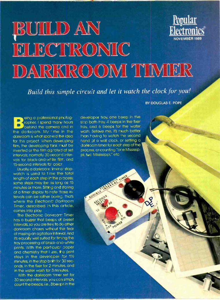
f
Popular
Electronics NOVEMBER 1989
r1-17vr D
Build this simple circuit and let it watch the clockfor you!
Being a professional photog- rapher, I spend many hours behind the camera cnd in
the darkroom. My - me In the darkroom is what spar4ed the idea for this project. When developing film, the developing Conk rnaist be inverted or the film ag -oleo at set intervals; normally 30 -, ecord inter- vals for black-and-write fills, and 15- second intervals fo- colcr
Usually, a darkroom -ümer co- stop- watch is used to t me the total length of each step it the process; some steps may be as Iona as 15
minutes or more. Sitting and staring at a timer display to rote -hose in-
tervals can be rather borin =. That's
where the Electrons: Darkroom Timer, described in this article, comes into play.
The Electronic Daricroa'r- Timer has a buzzer that beeps at areset intervals, so you are free to do other darkroom chores without the fear of missing an agitation interval. And it's equally well suited for tir i rg the tray processing of black -a-ic -white prints. With the partculc= Japer and chemistry that I use, iite print stays in the developer `or 11/2
minutes, in the stop bait for 30 sec- onds, in the fixer for 2 minutes, and in the water wash for 3 minutes.
With the darkroom timer set for 30 second intervals, you ccn simply count the beeps; i.e, 3 beeps in the
BY DOUSLAS E. POPE
developer tray, one beep in the sop both tay, 4 beeps in the tier tray, cnd b beeps for the water wcsh. 3elie 'e me, Ws much better tan raving to watch second hand of a wall clock, or setting a darkroom truer for eact- step of the process, crcounting "ore Mississip-
pi, twc Mississippi," etc.
AmericanRadioHistory.Com
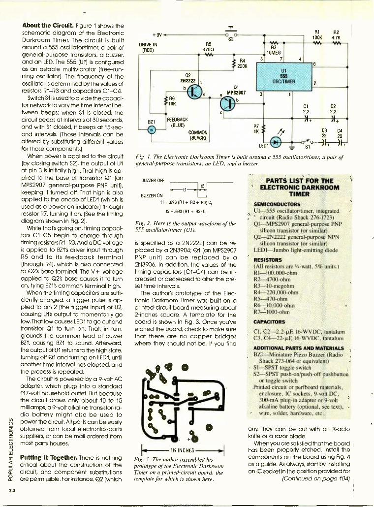
34
About the Circuit. Figure 1 shows the schematic diagram of the Electronic Darkroom Timer. The circuit is built around a 555 oscillator /timer, a pair of general -purpose transistors, a buzzer, and an LED. The 555 (U1) is configured as an astable multivibrator (free -run- ning oscillator). The frequency of the oscillator is determined by the values of resistors RI-R3 and capacitors CI-C4.
Switch S1 is used to divide the capaci- tor network to vary the time interval be- tween beeps; when S1 is closed, the circuit beeps at intervals of 30 seconds, and with S1 closed, it beeps at 15 -sec- ond intervals. (Those intervals can be altered by substituting different values for those components.)
When power is applied to the circuit (by closing switch S2), the output of U1
at pin 3 is initially high. That high is ap- plied to the base of transistor Q1 (an MPS2907 general -purpose PNP unit), keeping it turned off. That high is also applied to the anode of LEDI (which is
used as a power on indicator) through resistor R7, turning it on. (See the timing diagram shown in Fig. 2).
While that's going on, timing capaci- tors CI-05 begin to charge through timing resistors R1 -R3. And a DC voltage is applied to BZ1's driver input through R5 and to its feedback terminal (through R4), which is also connected to Q2's base terminal. The V+ voltage applied to Q2's base causes it to turn on, tying BZ1's common terminal high.
When the timing capacitors are suffi- ciently charged, a trigger pulse is ap- plied to pin 2 (the trigger input) of U2, causing U1's output to momentarily go low. That low causes LEDI to go out and transistor Q1 to turn on. That, in turn, grounds the common lead of buzzer BZ1, causing BZ1 to sound. Afterward, the output of U1 returns to the high state, turning off Q1 and turning on LEDI, until another time interval has elapsed, and the process is repeated.
The circuit is powered by a 9 -volt AC adapter, which plugs into a standard 117 -volt household outlet. But because the circuit draws only about 10 to 15 milliamps, a 9 -volt alkaline transistor -ra- dio battery might also be used to power the circuit. All parts can be easily obtained from local electronics -parts suppliers, or can be mail ordered from most parts houses.
Putting It Together. There is nothing critical about the construction of the circuit, and component substitutions are permissible. For instance, Q2 (which
+ 9V
DRIVE IN
(RED)
02 2N2222
b
R6 10K
R5
47052
Z 0 0
S2
BZ1 FEEDBACK
(BLUE)
COMMON (BLACK)
R4
220K
01
W. R3
10MEG
8 7 4
R1 R2 100K 4.7K
:.'. y1r
U1
555
OSC/TIMER
R7 1K
6
2
Fig. 1. The Electronic Darkroom Timer is built around a 555 oscillator /timer, a pair of general - purpose transistors, an LED, and a buzzer.
BUZZER OFF
t1 t2
BUZZER ON
t1 = .693 (R1 + R2 + R3 C,
t2 = .693 (R1 + R2) C,
Fig. 2. Here is the output waveform of the 555 oscillator /timer (UI).
is specified as a 2N2222) can be re- placed by a 2N3904; Q1 (an MPS2907 PNP unit) can be replaced by a 2N3906. In addition, the values of the timing capacitors (C1 -C4) can be in- creased or decreased to alter the pre- set time intervals.
The author's prototype of the Elec- tronic Darkroom Timer was built on a printed- circuit board measuring about 2- inches square. A template for the board is shown in Fig. 3. Once you've etched the board, check to make sure that there are no copper bridges where they should not be. If you find
1,9
%com"
o - -- -13/4 INCHES --I
Fig. 3. The author assembled his prototype of the Electronic Darkroom Timer on a printed- circuit board, the template for which is shown here.
PARTS LIST FOR THE ELECTRONIC DARKROOM
TIMER
SEMICONDUCTORS U1 -555 oscillator /timer, integrated
circuit (Radio Shack 276 -1723) Ql- MPS2907 general- purpose PNP
silicon transistor (or similar) Q2- 2N2222 general -purpose NPN
silicon transistor (or similar) LEDI -Jumbo light- emitting diode
RESISTORS (All resistors are 1/4-watt, 5% units.) R1- 100,000 -ohm R2 -4700 -ohm R3- 10- megohm R4- 220,000 -ohm R5-470-ohm R6- 10,000 -ohm R7 -1000 -ohm
CAPACITORS
CI, C2- 2.2 -µF, I6 -WVDC, tantalum C3. C4- 22 -11F, 16 -WVDC, tantalum
ADDITIONAL PARTS AND MATERIALS BZ1- Miniature Piezo Buzzer (Radio
Shack 273 -064 or equivalent) S1 -SPST toggle switch S2 -SPST push -on /push -off pushbutton
or toggle switch Printed circuit or perfboard materials,
enclosure, IC sockets, 9 -volt DC, 300 -mA plug -in adapter or 9 -volt alkaline battery (optional, see text), wire, solder, hardware, etc.
any, they can be cut with an X -acto knife or a razor blade.
When you are satisfied that the board has been properly etched, install the components on the board using Fig. 4 as a guide. As always, start by installing an IC socket in the position provided for
(Continued on page 104)
AmericanRadioHistory.Com
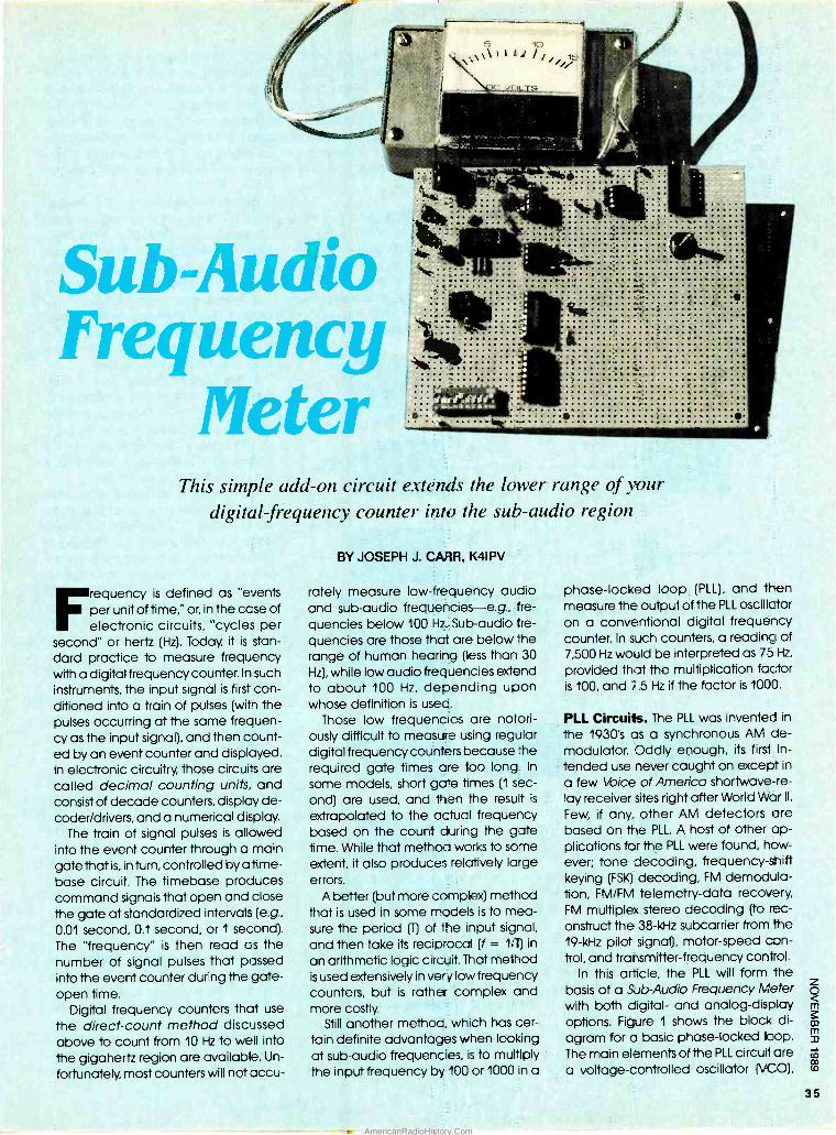
5 147
1\\ \ 1 1 1 /
Sub -Audio Frequency
Meter
.... . .......... ...... 74ies.
...
. .' ..::::,...
This simple add -on circuit extends the lower range of your digital frequency counter into the sub -audio region
Frequency is defined as "events per unit of time," or, in the ccse of electronic circuits, "cycles per
second" or hertz (Hz). Today, it is stan- dard practice to measure frequency with a digital frequency counter. In such instruments, the input signal is first con- ditioned into a train of pulses (witn the pulses occurring at the same frequen- cy as the input signal), and then count- ed by an event counter and displayed. In electronic circuitry, those circuits are called decimal counting units, and consist of decade counters, display de- coder /drivers, and a numerical display.
The train of signal pulses is allowed into the event counter through a main gate that is, in turn, controlled by a time - base circuit. The timebase produces command signals that open and close the gate at standardized intervals (e.g.,
0.01 second, 0.1 second, or 1 second). The "frequency" is then read os the number of signal pulses that passed into the event counter during the gate - open time.
Digital frequency counters that use
the direct -count method discussed above to count from 10 Hz to well into the gigahertz region are available. Un-
fortunately, most counters will not accu-
BY JOSEPH J. CARR, K4IPV
rately measure low -frequency audio and sub -audio frequencies -e.g., fre-
quencies below 100 Hz. Sub -audio fre-
quencies are those that are below the range of human hearing (less than 30
Hz), while low audio frequencies extend to about 100 Hz, depending upon whose definition is used.
Those low frequencies are notori- ously difficult to measure using regular digital frequency counters because the required gate times are too long. In
some models, short gate times (1 sec- ond) are used, and then the result is
extrapolated to the actual frequency based on the count during the gate time. While that method works to some extent, it also produces relatively large errors.
A better (but more complex) method that is used in some models is to mea- sure the period (T) of the input signal, and then take its reciprocal (f = 1 /1) in
an arithmetic logic circuit. That method is used extensively in very low frequency counters, but is rather complex and more costly.
Still another method, which has cer- tain definite advantages when looking at sub -audio frequencies, is to multiply the input frequency by 100 or 1000 in a
phase -locked loop (PLL), and then measure the output of the PLL oscillator on a conventional digital frequency counter. In such counters, a reading of 7,500 Hz would be interpreted as 75 Hz,
provided that the multiplication factor is 100, and 7.5 Hz if the factor is 1000.
PLL Circuits. The PLL was invented in
the 1930's as a synchronous AM de- modulator. Oddly enough, its first in- tended use never caught on except in
a few Voice of America shortwave- re-
lay receiver sites right after World War II.
Few, if any, other AM detectors are based on the PLL. A host of other ap- plications for the PLL were found, how- ever; tone decoding, frequency -sniff keying (FSK) decoding, FM demodula- tion, FM /FM telemetry -data recovery, FM multiplex stereo decoding (to rec- onstruct the 38 -kHz subcarrier from the 19 -kHz pilot signal), motor -speed con- trol, and transmitter- frequency control.
In this article, the PLL will form the basis of a Sub -Audio Frequency Meter with both digital- and analog -display options. Figure 1 shows the block di- agram for a basic phase -locked loop. The main elements of the PLL circuitare a voltage -controlled oscillator NCO),
35
AmericanRadioHistory.Com
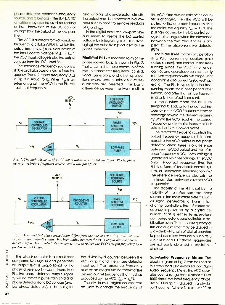
36
phase detector, reference -frequency source, and a low -pass filter (LPF). A DC amplifier may also be used for scaling or level translation of the DC control voltage from the output of the low -pass filter.
The VCO is a special form of variable - frequency oscillator (VFO) in which the output frequency, fosbo, is a function of the input control voltage (Vlr). In Fig. 1,
the VCO input voltage is also the output voltage from the DC amplifier.
The reference -frequency source is a stable oscillator operating at a fixed fre- quency. The reference frequency (fret) in Fig. 1 is equal to fo. When fret is an external signal, the VCO in the PLL will track that frequency.
VIN VOLTAGE
CONTROLLED OSCILLATOR
and analog phase- detector circuits, the output must be processed in a low - pass filter in order to remove residuals of fo and fref'
In the digital case, the low -pass filter also serves to create the DC control voltage by integrating (i.e., time -aver- aging) the pulse train produced by the phase detector.
Modified PLL. A modified form of the phase -locked loop is shown in Fig. 2. That circuit is the more common of the two in transmitter -frequency control, signal generators, and other applica- tions where presentable, discrete fre- quencies are needed. The basic difference between the two circuits is
vco OUTPUT
fo
fo
REFERENCE FREQUENCY
SOURCE
fill
PHASE - SENSITIVE DETECTOR
LOW -PASS FILTER
V(t)
Fig. I. The main elements of a PLL are a voltage -controlled oscillator (VCO), phase detector, reference frequency source, and a low -pass filter.
VIN VOLTAGE
CONTROLLED OSCILLATOR
VCO
OUTPUT o
DIVIDE -BY -N COUNTER
Vs
REFERENCE FREQUENCY
SOURCE
I HEI
PHASE - SENSITIVE DETECTOR
LOW -PASS FILTER
V(t)
Fig. 2. This modified phase- locked loop differs from the one s/u o n in Fig. 1 in oily one respect; a divide -by -N counter has been added between the VCO output and the phase - detector input. The divide -by -N counter is used to reduce the VCO's output frequency by a predetermined factor.
The phase detector is a circuit that compares two signals and generates an output that is proportional to the phase difference between them. In a PLL, the phase- detector output signal, Vt, will be either a pulse train (in digital phase detectors) or a DC voltage (ana - lóg phase detectors). In both digital
the divide -by -N counter between the VCO output and the phase- detector input port. The reference frequency must be an integer sub -harmonic of the desired output frequency that must be produced by the VCO: fret = fo /N.
The divide -by -N digital counter can be used to change the frequency of
the VCO. If the division ratio of the coun- ter is changed, then the VCO will be pulled to the one new frequency that maintains the equality fref = fo /N. The pulling is caused by the DC control volt- age that changes when the difference between the Iwo frequencies is ap- plied to the phase- sensitive detector (PSD).
There are three modes of operation in a PLL: free -running, capture (also called search), and locked. In the free - running mode, the VCO is not under control, and operates on an essentially random frequency within its range. That condition is also called "unlocked" op- eration. The PLL is typically in the free - running mode for a brief period after turn /on, and after that will be free -run- ning only if a defect is present.
In the capture mode, the PLL is at- tempting to lock onto the correct fre- quency, so the VCO frequency tends to converge toward the desired frequen- cy. When the VCO reaches the correct frequency, and remains there, the PLL is
said to be in the locked mode. The reference frequency controls the
output frequency because it is com- pared to the VCO output in the phase detector. When there is a difference between the VCO output and the refer- ence frequency, a DC control voltage is
generated, which tends to pull the VCO onto the correct frequency. Thus, the PLL is a form of feedback control sys- tem, or "electronic servomechanism." The reference frequency also sets the minimum step between discrete VCO frequencies.
The stability of the PLL is set by the stability of the reference -frequency source. In the most stable systems, such as signal generators or transmitter - channel controllers, the reference fre- quency is provided by a crystal os- cillator that is either temperature compensated or operated inside a sta- bilization oven. The output frequency of the crystal oscillator may be divided in a divide -by -N chain of digital counters to produce a low frequency, such as 5 kHz, 1 kHz, or 100 Hz (those frequencies are not easily obtained in crystal os- cillators).
Sub -Audio Frequency Meter. The block diagram of Fig. 2 can be used as the basis for a phase -locked loop Sub - Audio Frequency Meter. The VCO oper- ates over a range that is either 100 or 1000 times the input frequency range. The VCO output is divided in a divide - by-N counter (where N is either 100 or
AmericanRadioHistory.Com
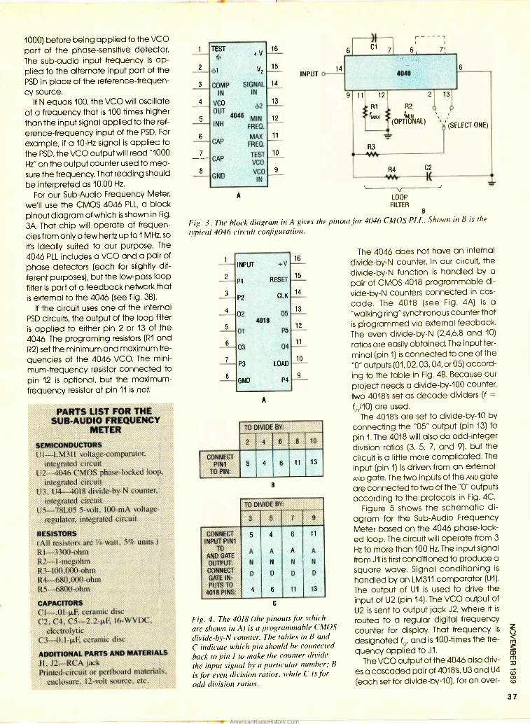
1000) before being applied to the VCO port of the phase- sensitive detector. The sub -audio input frequency is ap- plied to the alternate input port of the PSD in place of the reference- frequen- cy source.
If N equals 100, the VCO will oscillate at a frequency that is 100 times higher than the input signal applied to the ref-
erence- frequency input of the PSD. For
example, if a 10 -Hz signal is applied to the PSD, the VCO output will read "1000
Hz" on the output counter used to mea- sure the frequency. That reading should be interpreted as 10.00 Hz.
For our Sub -Audio Frequency Meter,
we'll use the CMOS 4046 PLL, a block pinout diagram of which is shown in Fig.
3A. That chip will operate at frequen- cies from only a few hertz up to 1 MHz, so
it's ideally suited to our purpose. The
4046 PLL includes a VCO and a pair of phase detectors (each for slightly dif- ferent purposes), but the low -pass loop filter is part of a feedback network that is external to the 4046 (see Fig. 3B).
If the circuit uses one of the internal PSD circuits, the output of the loop filter is applied to either pin 2 or 13 of the 4046. The programing resistors (R1 and R2) set the minimum and maximum fre-
quencies of the 4046 VCO. The mini-
mum- frequency resistor connected to pin 12 is optional, but the maximum - frequency resistor at pin 11 is not.
PARTS LIST FOR THE SUB -AUDIO FREQUENCY
METER
SEMICONDUCTORS U I LM 311 voltage- comparator.
integrated circuit U2 -4046 CMOS phase -locked loop,
integrated circuit U3, U4 4018 divide -by -N counter.
integrated circuit U5 -78L05 5 -volt, 100 -mA voltage -
regulator, integrated circuit
RESISTORS (All resistors are 1/4-watt, 5% units.) RI-3300-ohm R2- 1- megohm R3- 100,000-ohm R4- 680,000 -ohm R5 -6800 -ohm
CAPACITORS C1- .0I -pF, ceramic disc C2, C4, C5- 2.2 -11F, l6 -WVDC,
electrolytic C3-41.1-11F, ceramic disc
ADDITIONAL PARTS AND MATERIALS
JI, J2 -RCA jack Printed -circuit or pertboard materials,
enclosure, 12 -volt source, etc.
3
5
7
TEST (I)
(51
COMP IN
VCO
OUT
INH
CAP
CAP
GND
VZ
SIGNAL IN
4046
(1) 2
MIN FRED.
MAX FRED.
TEST
VCO
VCO
IN
16
15
14
13
12
A
11
10
9
INPUT
R2
'MIN (OPTIONAL)
LOOP FILTER
B
Fig. 3. The block diagram in A gives the pinout for 4046 CMOS PLL. Shown in B is the
typical 4046 circuit configuration.
INPUT +V 16
2 P1 RESET .
15
3 P2 CLK
14
13 02 05
4018 12
01 P5
11 03 04
7 P3 LOAD
10
GND P4 9- A
TO DIVIDE BY:
2 4 6 8 10
CONNECT PINI
TO PIN:
5 4 6 11 13
B
TO DIVIDE BY:
3 5 7 9
CONNECT INPUT PINI
TO
AND GATE
OUTPUT; CONNECT GATE IN- PUTS TO
4018 PINS:
5
A
N
D
4
4
A
N
D
6
6
A
N
D
11
11
A
N
D
13
C
Fig. 4. The 4018 (the pinouts for which
are shown in A) is a programmable CMOS
divide -by -N counter. The tables in B and
C indicate which pin should be connected
back to pin I to make the counter divide the input signal by a particular number; B
is for even division ratios, while C is for odd division ratios.
The 4046 does not have an internal
divide -by -N counter. In our circuit, the divide -by -N function is handled by a
pair of CMOS 4018 programmable di-
vide-by-N counters connected in cas-
cade. The 4018 (see Fig. 4A) is a
"walking ring" synchronous counter that is Orogrammed via external feedback. The even divide -by -N (2,4,6,8 and 10)
ratios are easily obtained. The input ter-
minal (pin 1) is connected to one of the "0" outputs (01, 02, 03, 04, or 05) accord- ing to the table in Fig. 4B. Because our
project needs a divide -by -100 counter, Iwo 4018's set as decade dividers (f =
fn /10) are used. The 4018's are set to divide -by -10 by
connecting the "05" output (pin 13) to pin 1. The 4018 will also do odd -integer division ratios (3, 5, 7, and 9), but the circuit is a little more complicated. The
input (pin 1) is driven from an external AND gate. The Iwo inputs of the AND gate are connected to Iwo of the "0" outputs according to the protocols in Fig. 4C.
Figure 5 shows the schematic di- agram for the Sub -Audio Frequency Meter based on the 4046 phase -lock- ed loop. The circuit will operate from 3
Hz to more than 100 Hz. The input signal from J1 is first conditioned to produce a
square wave. Signal conditioning is
handled by an LM311 comparator (U1).
The output of U1 is used to drive the input of U2 (pin 14). The VCO output of U2 is sent to output jack J2, where it is
routed to a regular digital frequency counter for display. That frequency is
designated fo, and is 100 -times the fre-
quency applied to J1.
The VCO output of the 4046 also driv-
es a cascaded pair of 4018's, U3 and U4
(each set for divide- by -10), for an over-
37
AmericanRadioHistory.Com
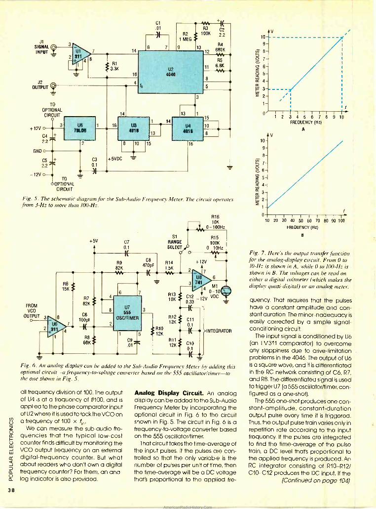
38
J1
SIGNAL (pj INPUT -
J2 OUTPUT 4
+12V
3
U1 7
2 311 4
1
8
14
R1
3.3K 16
TO
OPTIONAL CIRCUIT
3
C4 + 2.2
GND
- 12V
78105
C5 + 2.2
TO - OPTIONAL CIRCUIT
C3
0.1
16
14
Cl .01
0 13
vsos. +I R3 100K
U2
4046
U3 4018
10
+5VDC
14
13
3
13
U4 4018
16
12
11
C2
2.2
R4
680K 404 R5
6.8K -1VNr
15
10
8
Fig. 5. The schematic diagram for the Sub -Audio Frequency Meter. The circuit operates from 3 -Hz to more than 100 -Hz.
FROM VCO
OUTPUT 3 o
8
R6 , 15K
U6 7 ? +311
1
+ 5V C7
0.1
R7
82K
C6 100pF
v
R8 . 68K :
4
8
R9 C8
82K 470pF
6
U7
555 OSC/TIMER
C9
.01 T 15
3
R10 12K
s1 RANGE SELECT p 0'o
R14 1.5K SNA.
R13
R16 4L10K
0-100Hz
R15 100K
0-10Hz
41* +12V
7
U8 3+41
M1 4 0-10
10K C12 -12V VDC
0.33
R12 12K
R11
12K
I(
C11
0.1
C10 0.1
INTEGRATOR
Fig. 6. An analog display can be added to the Sub -Audio Frequency Meter by adding this optional circuit -a frequency -to- voltage converter based on the 555 oscillator /timer -to the one shown in Fig. 5.
all frequency division of 100. The output of U4 is at a frequency of f /100, and is
applied to the phase comparator input of U2 where it is used to lock the VCO on a frequency of 100 x
We can measure the sub -audio fre- quencies that the typical low -cost counter finds difficult by monitoring the VCO output frequency on an external digital- frequency counter. But what about readers who don't own a digital frequency counter? For them, an ana- log indicator is also provided.
Analog Display Circuit. An analog display can be added to the Sub -Audio Frequency Meter by incorporating the optional circuit in Fig. 6 to the circuit shown in Fig. 5. The circuit in Fig. 6 is a frequency -to- voltage converter based on the 555 oscillator /timer.
That circuit takes the time -average of the input pulses. f the pulses are con- trolled so that the only variable is the number of pulses per unit of time, then the time -average will be a DC voltage that's proportional to the applied fre-
° 6- z E 5- cr 4-
3-
2- 1-
V
0' r
10-
9- 8-
V
i
i l i i
1 2 3 4 5 6 7 8 9 10
FREQUENCY (Hz)
i1
A
10 20 30 40 50 60 70 80 90 100
FREQUENCY (Hz)
B
Fig. 7. Here's the output transfer function for the analog- display circuit. From 0 to 10 -Hz is shown in A, while 0 to 100 -Hz is shown in B. The voltages can be read on either a digital voltmeter (which makes the display quasi- digital) or an analog meter.
quency. That requires that the pulses have a constant amplitude and con- stant duration. The minor inadequacy is
easily corrected by a simple signal - conditioning circuit.
The input signal is conditioned by U6 (an LM311 comparator) to overcome any sloppiness due to drive -limitation problems in the 4046. The output of U6 is a square wave, and it is differentiated in the RC network consisting of C6, R7, and R8. The differentiated signal is used to trigger U7 (a 555 oscillator/timer, con- figured as a one -shot).
The 555 one -shot produces one con- stant- amplitude, constant -duration output pulse every time it is triggered. Thus, the output pulse train varies only in repetition rate according to the input frequency. If the pulses are integrated to find the time -average of the pulse train, a DC level that's proportional to the applied frequency is produced. An RC integrator consisting of R10 -R12/ C10-C12 produces the DC input. If the
(Continued on page 104)
AmericanRadioHistory.Com
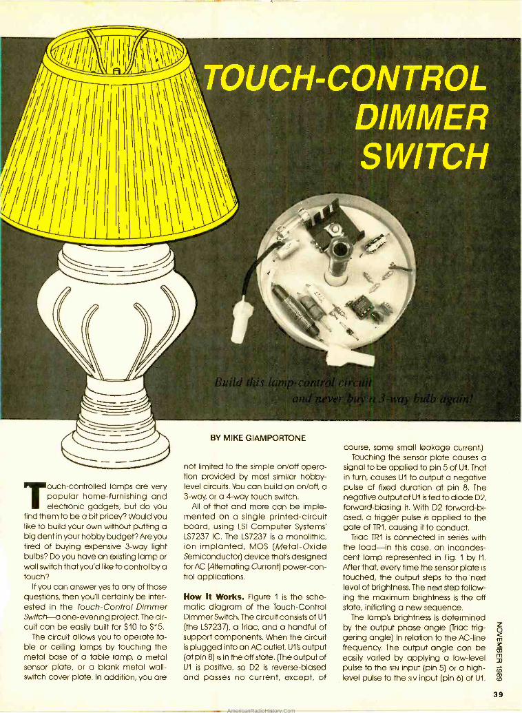
Touch -controlled lamps are very popular home -furnishing and electronic gadgets, but do you
find them to be a bit pricey? Would you like to build your own without putting a big dent in your hobby budget? Are you tired of buying expensive 3 -way light bulbs? Do you have an existing lamp or wall switch that you'd like to control by a touch?
If you can answer yes to any of those questions, then you'll certainly be inter- ested in the Touch- Control Dimmer Switch a one -evening project. The cir- cuit can be easily built for $10 to $'5.
The circuit allows you to operate ta- ble or ceiling lamps by touching the metal base of a table lamp, a metal sensor plate, or a blank metal wall - switch cover plate. In addition, you are
BY MIKE GIAMPORTONE
not limited to the simple on /off opera- tion provided by most similar hobby - level circuits. You can build an on /off, a 3 -way, or a 4 -way touch switch.
All of that and more can be imple- mented on a single printed- circuit board, using LSI Computer Systems' LS7237 IC. The LS7237 is a monolithic, ion -implanted, MOS (Metal -Oxide Semiconductor) device that's designed for AC (Alternating Current) power -con- trol applications.
How It Works. Figure 1 is the sche- matic diagram of the Touch -Control Dimmer Switch. The circuit consists of U1
(the LS7237), a Triac, and a handful of support components. When the circuit is plugged into an AC outlet, U1's output (at pin 8) is in the off state. (The output of U1 is positive, so D2 is reverse-biased and passes no current, except, of
course, some small leakage current.) Touching the sensor plate causes a
signal to be applied to pin 5 of U1. That in turn, causes U1 to output a negative pulse of fixed duration at pin 8. The negative output of U1 is fed to diode D2, forward -biasing it. With D2 forward -bi- ased, a trigger pulse is applied to the gate of TR1, causing it to conduct.
Triac TR1 is connected in series with the load -in this case, an incandes- cent lamp represented in Fig. 1 by 11.
After that, every time the sensor plate is
touched, the output steps to the next level of brightness. The next step follow- ing the maximum brightness is the off state, initiating a new sequence.
The lamp's brightness is determined by the output phase angle (Triac trig- gering angle) in relation to the AC -line frequency. The output angle can be easily varied by applying a low -level pulse to the SEN input (pin 5) or a high - level pulse to the sLv input (pin 6) of U1.
39
AmericanRadioHistory.Com
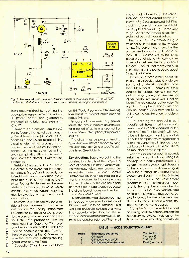
40
H
117 VAC
TR1
6A 400PIV
Cl 15
NEUTRAL
N
R2
1.5MEG
C2
.22
)I
D3
1N4744A 15V
ZENER
C5
47 ..
N D1
1N4148
D2 1 1144148
8
R3
680K .AM,
7 6
OUT Voo SLV
ss Ui SENS LS7237
CAP SYNC
3 4
* SEE TEXT
C3 _ C4 y 470pF .47 7
SENSOR PLATE
R6 2.7MEG
R5 2.7MEG
H C6
680pF
---VV1r R4*
1MEG-5MEG
Fig. I. The Touch -Control Dimmer Switch consists of little more than Ul (an LS7237 touch -controlled dimmer switch), a triac, and a handful of support components.
Tha1s accomplished by touching the appropriate sensor plate. The internal PLL (Phase- Locked Loop) guarantees the exact same brightness levels from IC to IC.
Power for U1 is derived from the AC
line by feeding the line voltage through a 15 -volt Zener diode (D3) and D1. Ca- pacitors C2 and C5 are included in the circuit to help maintain a constant volt- age for the circuit. Resistor R2 and ca- pacitor C4 filter the signal fed to the SYNC input (pin 4) of U1, which is used to synchronize the internal PLL with the line frequency.
Resistor R3 is used to limit current in
the circuit in the event that the exten- sion circuits (if used) are incorrectly po- larized. If extensions are not used, the SO/
input (pin 6) should be tied to pin 7
(VDD). Resistor R4 determines the sen- sitivity of the SEN input. Its value, which can range between land 5 megohms, must be selected through the trial and error method.
Resistors R5 and R6 are Iwo series re-
sistors placed between you and the cir- cuit, and are required by Underwriters Laboratories standards for your protec- tion. In case of one resistor shorting out, you'll still have protection from the household lines. Capacitor C3 is used as a filter for U1's internal PLL. Diode D2 is
used to decouple the Triac from U1,
thereby protecting the IC from excur- sions that may occur during the trig- gered state of some Triacs.
Capacitor C1 and inductor L1 form
an RFI (Radio -Frequency interference) filter circuit, to prevent interference to radios, TV's, etc.
In case of a momentary power failure, the circuit remains unchanged for a period of up to one second. For
longer power interruptions, the power is
shut off. The circuit may be programmed to
operate in one of three modes by tying the MODE input (pin 2) to a specific volt- age level. (See Table 1).
Construction. Before we get into the construction details of the project, a word of caution is in order: When work- ing with household current, you must be especially careful. The Touch -Control Dimmer Switch should be installed in a plastic enclosure. Testing or operating the circuit outside of the enclosure or in
one that is open is dangerous, because the circuit -board traces and heat sink
carry household current. Before assembly can begin, you must
first decide where your Touch -Control Dimmer Switch is to be installed -in a wall junction box, in the base of a lamp, in a separate project box, etc. The in-
tended location of the board will deter- mine its shape. For instance, if the circuit
is to control a table lamp, the round - shaped, printed- circuit template shown in Fig. 2 should be used. But, if the circuit is to control an overhead light, the template shown in Fig. 3 is the way to go. Choose the printed- circuit tern- plate that best suits your situation.
The round template shown in Fig. 2
fits under or in the base of many table lamps. The center hole should be the proper size for your lamp. I used a 1/2-
(O,D.), .062 -inch wall, 7/8 -inch long, piece of polyethylene tubing, for a shim or insulator between the lamp rod and the circuit board. That makes the hole in the center of the round board about Y2 inch in diameter.
The round printed- circuit board fits
nicely in a discarded plastic enclosure from a roll of electric tape (like those that 3M's Super 33 + comes in). If you decide to replace an existing wall switch, the rectangular pattern (see Fig.
3) fits neatly into most wall junction boxes. The rectangular pattern also fits
well in many plastic enclosures and can be located away from the lamp being controlled, like under a table or couch.
After etching the printed- circuit board(s), drill holes for all the compo- nents. The size of holes required for the fuse clips, Triac, RFI filter, and R1 will have to be a little larger than those for the rest of the components. It's a good idea to drill the center hole in the round cir- cuit board at this point, if the circuit is to be mounted on the lamp rod.
Once the board has been prepared, install the parts on the board using the appropriate parts -placement di- agram; the parts- placement diagram for the round version is shown in Fig. 4,
while the rectangular version's parts - placement diagram is in Fig. 5. Note: The lamp, 11, in either parts -placement diagram is not part of the circuit: it rep- resents the lamp being controlled by the circuit. Whichever version you choose to assemble, it may be neces- sary to reduce the size of the heat sink.
Heat sinks come in various sizes, de- pending on the manufacturer.
Mount the Triac in the well of the heat sink, using heat sink compound and the necessary hardware. Insulators of the type used when mounting transistors to
Mode o 1
2
TABLE 1 -MODE SELECTION CHART
Brightness sequence Off max off Off mood med max /off Off nightrmood: med /max /off
Tie pin 2 to: Vss (pin 1)
Vdd (pin 7) Float (no conn.)
AmericanRadioHistory.Com
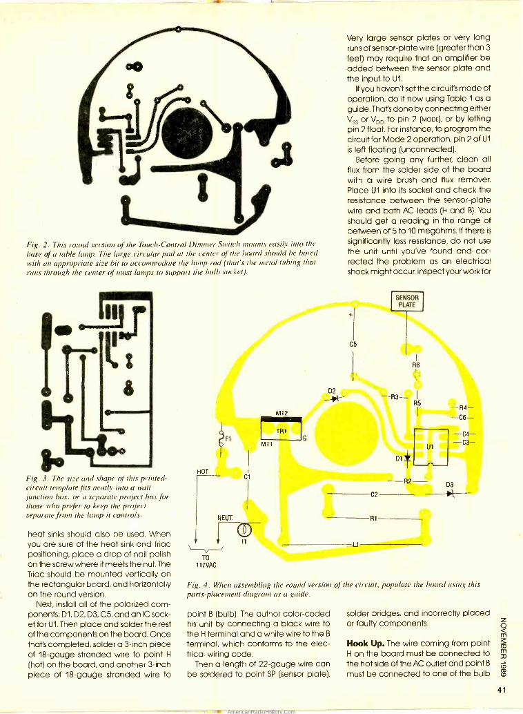
Fig. 2. This round version of the Touch- Control Dimmer Switch mounts easily into the
base of a table lamp. The large circular pad at the center of the board should be bored with an appropriate size bit w accommodate the lamp rod (that's the metal tubing that runs through the center of most lamps to support the bulb socket).
1 F[1:
N Fig. 3. The size and shape of this printed - circuit template fits neatly into a wall junction box, or a separate project box for those who prefer to keep the project separate from the lamp it controls.
heat sinks should also be used. When you are sure of the heat sink and Triac positioning, place a drop of nail polish on the screw where it meets the nut. The Triac should be mounted vertically on the rectangular board, and horizontally on the round version.
Next, install all of the polarized com- ponents; D1, D2, D3, C5, and an IC sock- et for U1. Then place and solder the rest of the components on the board. Once that's completed, solder a 3 -inch piece of 18 -gauge stranded wire to point H
(hot) on the board, and another 3 -inch piece of 18 -gauge stranded wire to
HOT
Very large sensor plates or very long runs of sensor -plate wire (greater than 3
feet) may require that an amplifier be added between the sensor plate and the input to U1.
If you haven't set the circuit's mode of operation, do it now using Table 1 as a guide. That's done by connecting either Vss or VDD to pin 2 (MODE), or by letting pin 2 float. For instance, to program the circuit for Mode 2 operation, pin 2 of U1
is left floating (unconnected). Before going any further, clean all
flux from the solder side of the board with a wire brush and flux remover. Place U1 into its socket and check the resistance between the sensor -plate wire and both AC leads (H and B). You
should get a reading in the range of between of 5 to 10 megohms. If there is
significantly less resistance, do not use the unit until you've found and cor- rected the problem as an electrical shock might occur. Inspect your work for
ISENSOR PLATE l
TR1
C
C2
NEUT. R1
i It L1
TO
117VAC
Fig. 4. When assembling the round version of the circuit, populate the board using this parts -placement diagram as a guide.
point B (bulb). The author color -coded his unit by connecting a black wire to the H terminal and a white wire to the B
terminal, which conforms to the elec- trical wiring code.
Then a length of 22 -gauge wire can be soldered to point SP (sensor plate).
solder bridges, and incorrectly placed or faulty components.
Hook Up. The wire coming from point H on the board must be connected to the hot side of the AC outlet and point B
must be connected to one of the bulb
41
AmericanRadioHistory.Com
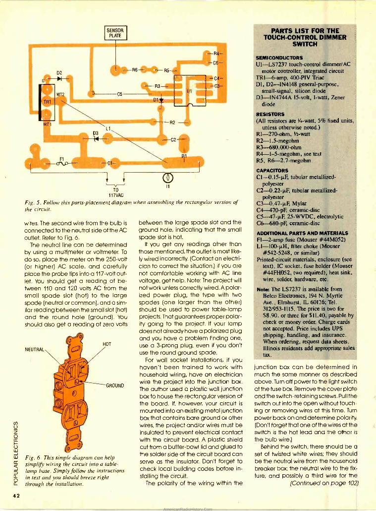
42
TO
117VAC
Fig. 5. Follow this parts -placement diagram when assembling the rectangular version of the circuit.
R1
- R4-
-C6--
-C4 -C3
wires. The second wire from the bulb is
connected to the neutral side of the AC outlet. Refer to Fig. 6.
The neutral line can be determined by using a multimeter or voltmeter. To
do so, place the meter on the 250 -volt (or higher) AC scale, and carefully place the probe tips into a 117 -volt out- let. You should get a reading of be- tween 110 and 120 volts AC from the small spade slot (hot) to the large spade (neutral or common), and a sim- ilar reading between the small slot (hot) and the round hole (ground). You should also get a reading of zero volts
NEUTRAL HOT
II GROUND
0
Fig. 6. This simple diagram can help simplify wiring the circuit into a table - lamp base. Simply follow the instructions in text and you should breeze right through the installation.
between the large spade slot and the ground hole, indicating that the small spade slot is hot.
If you get any readings other than those mentioned, the outlet is most like- ly wired incorrectly. (Contact an electri- cian to correct the situation.) If you are not comfortable working with AC line voltage, get help. Note: The project will not work unless correctly wired. A polar- ized power plug, the type with two spades (one larger than the other) should be used to power table -lamp projects. That guarantees proper polar- ity going to the project. If your lamp does not already have a polarized plug and you have a problem finding one, use a 3 -prong plug, even if you don't use the round ground spade.
For wall socket installations, if you haven't been trained to work with household wiring, have an electrician wire the project into the junction box. The author used a plastic wall junction box to house the rectangular version of the board. If, however, your circuit is
mounted into an existing metal junction box that contains bare ground or other wires, the project and /or wires must be insulated to prevent electrical contact with the circuit board. A plastic shield cut from a butter -bowl lid and glued to the solder side of the circuit board can serve as the insulator. Don't forget to check local building codes before in- stalling the circuit.
The polarity of the wiring within the
PARTS LIST FOR THE TOUCH -CONTROL DIMMER
SWITCH
SEMICONDUCTORS Ul- LS7237 touch -control dimmer /AC
motor controller, integrated circuit TRI- 6-amp, 400 -PIV Triac Dl, D2- 1N4148 general -purpose,
small -signal. silicon diode D3- 1N4744A 15 -volt, 1 -watt, Zener
diode
RESISTORS (All resistors are %d -watt, 5% fixed units.
unless otherwise noted.) RI -270 -ohm, 1/2-watt
R2 -1.5- megohm R3- 680.000 -ohm R4- 1- 5- megohm, see text R5. R6 -2.7- megohm
CAPACITORS C1-0.15-4 tubular metallized -
polyester C2- O.22 -p,F, tubular metallized -
polyester C3- 0.47 -1.LF, Mylar C4-470 pF, ceramic -disc C5- 47 -µF, 25 -WVDC, electrolytic C6- 680 -pF, ceramic -disc
ADDITIONAL PARTS AND MATERIALS Fl -2 -amp fuse (Mouser #44M052) Ll- l00 -p,H, filter choke (Mouser
#542 -5248, or similar) Printed- circuit materials, enclosure (see
text), IC socket. fuse holder (Mouser #44FH052, two required), heat sink. wire, solder, hardware, etc.
Note: The LS7237 is available from Belco Electronics, 194 N. Myrtle Ave., Elmhurst, IL 60126; Tel. 312 /953 -1115. The price is two for $8.90. or three for $11.40. payable by check or money order. Charge cards not accepted. Price includes UPS shipping, handling, and insurance. When ordering, request data sheets. Illinois residents add appropriate sales tax.
junction box can be determined in much the same manner as described above. Turn off power to the light switch at the fuse box. Remove the cover plate and the switch- retaining screws. Pull the switch out into the open without touch- ing or removing wires at this time. Turn
power back on and determine polarity. (Don't forget that one of the wires at the switch is the hot lead and the other is
the bulb wire.) Behind the switch, there should be a
set of twisted white wires; they should be the neutral wire from the household breaker box; the neutral wire to the fix- ture; and possibly a third wire for the
(Continued on page 102)
AmericanRadioHistory.Com
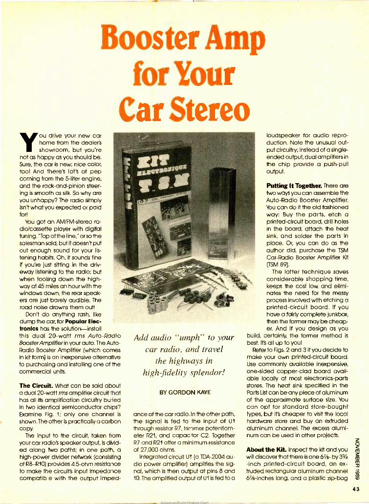
Booster Amp for Your
Car Stereo ou drive your new car home from the dealer's showroom, but you're
not as happy as you should be. Sure, the car is new; nice color, too! And there's lot's of pep coming from the 5 -liter engine, and the rack -and -pinion steer- ing is smooth as silk. So why are you unhappy? The radio simply isn't what you expected or paid for!
You got an AM /FM- stereo ra- dio /cassette player with digital tuning. "Top of the line," or so the salesman said, but it doesn't put out enough sound for your lis-
tening habits. Oh, it sounds fine if you're just sitting in the driv- eway listening to the radio; but when tooling down the high- way at 45 miles an hour with the windows down, the rear speak- ers are just barely audible. The road noise drowns them out!
Don't do anything rash, like dump the car, for Popular Elec- tronics has the solution -install this dual 20 -watt rms Auto -Radio BoosterAmplifier in your auto, The Auto - Radio Booster Amplifier (which comes in kit form) is an inexpensive alternative to purchasing and installing one of the commercial units.
The Circuit. What can be said about a dual 20 -watt rms amplifier circuit that has all its amplification circuitry buried in two identical semiconductor chips? Examine Fig. 1; only one channel is
shown. The other is practically a carbon copy.
The input to the circuit, taken from your car radio's speaker output, is divid- ed along two paths; in one path, a high -power divider network (consisting of R8 -R10) provides 4.5 -ohm resistance to make the circuit's input impedance compatible with the output imped-
Add audio "umph" car radio, and travel
the highways in
high - fidelity splendor!
to your
BY GORDON KAYE
ance of the car radio. In the other path, the signal is fed to the input of U1
through resistor R7, trimmer potentiom- eter R21, and capacitor C2. Together R7 and R21 offer a minimum resistance of 27,000 ohms.
Integrated circuit U1 (a TDA -2004 au- dio power amplifier) amplifies the sig- nal, which is then output at pins 8 and 10. The amplified output of U1 is fed to a
loudspeaker for audio repro- duction. Note the unusual out- put circuitry; Instead of a single - ended output, dual amplifiers in
the chip provide a push -pull output.
Putting It Together. There are two ways you can assemble the Auto -Radio Booster Amplifier. You can do it the old fashioned way: Buy the parts, etch a printed- circuit board, drill holes in the board, attach the heat sink, and solder the parts in
place. Or, you can do as the author did, purchase the TSM
Car -Radio Booster Amplifier Kt (TSM 89).
The latter technique saves considerable shopping time, keeps the cost low, and elimi- nates the need for the messy process involved with etching a printed- circuit board. If you have a fairly complete junkbox, then the former may be cheap- er. And if you design as you
build, certainly, the former method is
best. Its all up to you! Refer to Figs. 2 and 3 if you decide to
make your own printed -circuit board. Use commonly available inexpensive, one -sided copper -clad board avail- able locally at most electronics -parts stores. The heat sink specified in the Parts List can be any piece of aluminum of the approximate surface size. You
can opt for standard store -bought types, but it's cheaper to visit the local hardware store and buy an extruded aluminum channel. The excess alumi- num can be used in other projects.
About the Kit. Inspect the kit and you will discover that there is one 67/8- by 33/4
-inch printed- circuit board, an ex- truded rectangular aluminum channel 67/8- inches long, and a plastic zip -bag
43
AmericanRadioHistory.Com
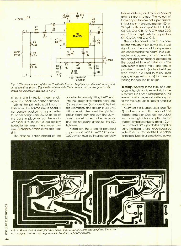
44
+12VDC
AUDIO INPUT
3,8 C8 %L, / C11 1007 T .1
9
R7 -2 7
1 27K 6.8 6
R21 4.7K
t R8 1.551
R9 t 1.552
t R10 1.552
11
C7 1+ loo
10
U1
TDA-2004
2 4
Cl + + C3 100 100
C5 68
+ f
C4
3 68
+IE +
C6
8 7100
4o
5
R3 R2
152 1K
C9 .1
R5 1052 { R6
1052
R1
1.8K
7 - CAR FRAME - GROUND
Fig. I. The two channels of the the Car -Radio Booster Amplifier are identical so only half of the circuit is shown. The numbered terminals (input, output, etc.) correspond to the
eleven -pin connector detailed in Fig. 3.
R4 152
C10 T .1
SPKR
of parts with instruction sheets pack- aged in a book -like plastic container.
Wiring the printed- circuit board is
fairly easy. The printed- circuit board is
not densely packed so opportunities for solder bridges are few. Solder all of the parts in place except the audio amplifier IC's. Those IC's are loosely bolted to the holes in the extruded alu- minum channel, which serves as a heat sink.
The channel is then placed on the
board while carefully fitting the IC leads into their respective mating holes. The IC's are polarized (so to speak) by their pin orientation, and as such those units will mate with the pre -drilled printed - circuit board only one way. The alumi- num channel is then bolted in place and the hardware attaching the IC's
tightened. In addition, there are 16 polarized
capacitors (C1 -C8, C12 -C17, C19, and C20), which must be inserted correctly
before soldering and then rechecked after all are in place. The values of those capacitors are not super critical; in fact, the kit may contain either 100- or 220 -µF units for capacitors Cl, C3, C6-C8, C12, C16, C17, C19, and C20; and 6.8- or 10 -1.1,F units for capacitors C2, C4, C5, and C13 -C15.
The kit also contains an 11 -pin con- nector, through which power, the input signal, and the output loudspeakers are connected to the board. That con- nector may be used, or it can be omit- ted and lead connections soldered to the board at time of installation. You
may elect to use a male and female polarized connector (such as the Molex type, which are used in many auto sound system installations) to make in-
stalling the circuit a bit easier.
Testing. Working in the trunk of a car, even a hatch back, especially in the summer's sun is not a wise practice. The winter months are just as hostile, so plan to test the Auto -Radio Booster Amplifier indoors.
Connect the loudspeakers (see Fig.
4) to the correct terminals of the booster amplifier. Connect the output from your high -fidelity amplifier to the booster amplifier's input terminals. Con- nect a 12 -volt DC supply to the amplifier using the fuse and fuse holder specified in the Parts List. Connect the fuse holder in the positive line as close to the power
Fig. 2. If you wish to make your own circuit board; use this same -size template. The extra
heavy copper runs are use to permit safe handling of heavy currents.
AmericanRadioHistory.Com
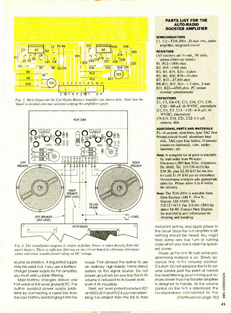
U1 C7 R3 R4
R2 I+
+
C11 C8
R6 Cg C10
C12
+
+ + C15 1+
R12 C13 C14
C17
U2
C16
R13
R14
1 2 3 4 5 6 7 8 9 10 11
E - z + H P E-z+ H P I
Fig. 3. Parts layout for the Car -Radio Booster Amplifier are shown here. Note that the
board is divided into two sections keeping the amplifiers apart.
R15 R19
+ Cl
C18+IC20 1 IC22
R16 R18 C21
HEAT SINK
O0
RIGHT SPEAKER
LEFT SPEAKER (HOT LEAD)
RIGHT SPEAKER
(HOT LEAD)
TO CAR FRAME
12VDC
P
Fig. 4. The installation diagram is simple to follow. Power is taken directly from the
auto's battery. There is sufficient filtering on the circuit board to eliminate alternator whine and noise usually found riding on DC voltage.
source as possible. A regulated supply may be used; but, if you use a battery - charger power supply for the amplifier, you must add suitable filtering.
Most battery chargers deliver raw half -wave or full -wave (pulsed) DC. The author avoided power supply prob- lems by connecting a fused line from the car's battery and bringing it into the
house. That allowed the author to use
an ordinary high -fidelity home -stereo system as the signal source. Do not power up just yet; be sure that the hi -fi's
volume is reduced to its lowest level - even if ifs inaudible.
Next, set level- potentiometers R21
and R22 (RV1 and RV2 if your are assem- bling the project from the kit) to their
PARTS LIST FOR THE AUTO -RADIO
BOOSTER AMPLIFIER
SEMICONDUCTORS UI , U2 -TDA -2004, 20 -watt rms, audio
amplifier, integrated circuit
RESISTORS (All resistors are %a -watt, 5% units,
unless otherwise noted.) RI. R12 -1800 -ohm R2, R15 -1000 -ohm R3, R4, RI9, R20-1 -ohm R5, R6, R16, R18-10 -ohm R7, R17-27,000-ohm R8 -RII, R13, R14 -1.5 -ohm, 2 -watt R21, R22- 4700 -ohm, PC -mount
trimmer potentiometer
CAPACITORS CI, C3, C6-C8, C12, C16, C17, C19,
C20- 100 -1 F 16 -WVDC, electrolytic C2, C4, C5, C13- C15- 6.8 -p.F, 16-
WVDC, electrolytic C9 --C1I, C18, C21, C22- 0.1 -11F,
ceramic disk
ADDITIONAL PARTS AND MATERIALS F1-6- ampere, slow -blow, type 3AG fuse Printed -circuit board, aluminum heat
sink, 3AG -type fuse holder, 11- contact connector (optional), wire, solder, hardware, etc.
Note: A complete kit of parts is available by mail order from Prospect Electronics (PO Box 9144, Allentown, PA 18105; Tel. 215/770 -9029) for $30.38, plus $2.50 S/H for the first kit (add $1.00 S/H per kit thereafter). Pennsylvania residents add appropriate sales tax. Please allow 6 to 8 weeks for delivery.
Note: The TDA -2004 is available from Parts Express (340 E. First St., Dayton, OH 45402: Tel. 513/222 -0173; Fax 513/461 -3391) for about $4.80. Contact Parts Express for availability and information on shipping and handling.
mid -point setting, and apply power to the circuit. Since the hi -fi amplifier is off,
nothing should be heard. You might hear some very low hum or rushing noise when your ear is near the speak - ers' cones.
Power up the hi -fi. Be sure some pro- gramming material is on. Slowly ad- vance the hi -fi's volume control. Caution: Do not advance the hi -fi's vol- ume control past the point of normal low -level listening; your hi -fi may put out more power than the booster amplifier is designed to handle! As the volume control on the hi -fi is advanced, the loudspeakers connected to the
(Continued on page 102)
45
AmericanRadioHistory.Com
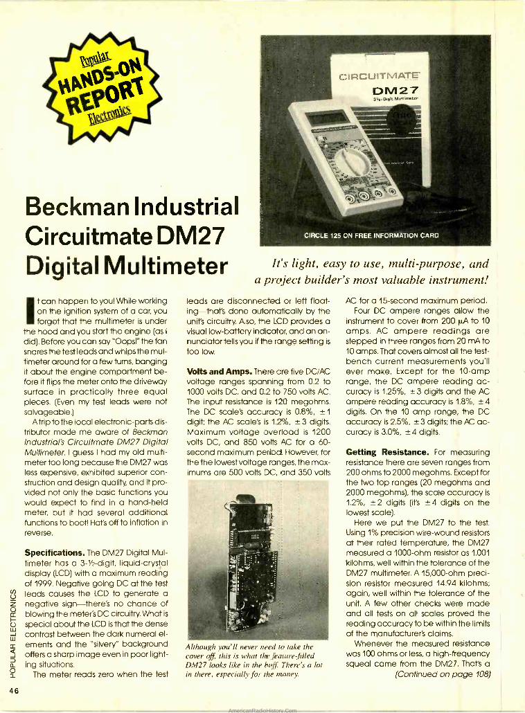
46
Beckman Industrial Circuitmate DM27 Digital Multimeter
It can happen to you! While working on the ignition system of a car, you forget that the multimeter is under
the hood and you start the engine (as I
did). Before you can say "Oops!" the fan snares the test leads and whips the mul- timeter around fora few turns, banging it about the engine compartment be- fore it flips the meter onto the driveway surface in practically three equal pieces. (Even my test leads were not salvageable.)
Atrip to the local electronic -parts dis- tributor made me aware of Beckman Industrial's Circuitmate DM27 Digital Multimeter. I guess I had my old multi - meter too long because the DM27 was less expensive, exhibited superior con- struction and design quality, and it pro- vided not only the basic functions you would expect to find in a hand -held meter, but it had several additional functions to boot! Hat's off to inflation in
reverse.
Specifications. The DM27 Digital Mul- timeter has a 3 -1/2- digit, liquid -crystal display (LCD) with a maximum reading of 1999. Negative going DC at the test leads causes the LCD to generate a negative sign- there's no chance of blowing the meter's DC circuitry. What is
special about the LCD is that the dense contrast between the dark numeral el- ements and the "silvery" background offers a sharp image even in poor light- ing situations.
The meter reads zero when the test
CIRCIJITMATE' DM27 3 z D gc MuttlmetCr
It's light, easy to use, multi -purpose, and a project builder's most valuable instrument!
leads are disconnected or left float- ing- that's done automatically by the unit's circuitry. Also, the LCD provides a visual low- battery indicator, and an an- nunciator tells you if the range setting is
too low.
Volts and Amps. There are five DC /AC voltage ranges spanning from 0.2 to 1000 volts DC, and 0.2 to 750 volts AC. The input resistance is 120 megohms. The DC scale's accuracy is 0.8 %, ± 1
digit; the AC scale's is 1.2%, ±3 digits. Maximum voltage overload is 1200 volts DC, and 850 volts AC for a 60- second maximum period. However, for the the lowest voltage ranges, the max- imums are 500 volts DC, and 350 volts
Although you'll never need to take the cover off, this is what the feature filled DM27 looks like in the buff There's a lot in there, especially for the money.
AC for a 15- second maximum period. Four DC ampere ranges allow the
instrument to cover from 200 ILA to 10
amps. AC ampere readings are stepped in three ranges from 20 mA to 10 amps. That covers almost all the test - bench current measurements you'll ever make. Except for the 10 -amp range, the DC ampere reading ac- curacy is 1.25 %, ±3 digits and the AC ampere reading accuracy is 1.8 %, ±4 digits. On the 10 amp range, the DC accuracy is 2.5 %, ± 3 digits; the AC ac- curacy is 3.0 %, ±4 digits.
Getting Resistance. For measuring resistance there are seven ranges from 200 ohms to 2000 megohms. Except for the two top ranges (20 megohms and 2000 megohms), the scale accuracy is
1,2 %, ±2 digits (it's ±4 digits on the lowest scale).
Here we put the DM27 to the test. Using 1% precision wire -wound resistors at their rated temperature, the DM27 measured a 1000 -ohm resistor as 1.001
kilohms, well within the tolerance of the DM27 multimeter. A 15,000 -ohm preci- sion resistor measured 14.94 kilohms; again, well within the tolerance of the unit. A few other checks were made and all tests on all scales proved the reading accuracy to be within the limits of the manufacturer's claims.
Whenever the measured resistance was 100 ohms or less, a high- frequency squeal came from the DM27. That's a
(Continued on page 108)
AmericanRadioHistory.Com
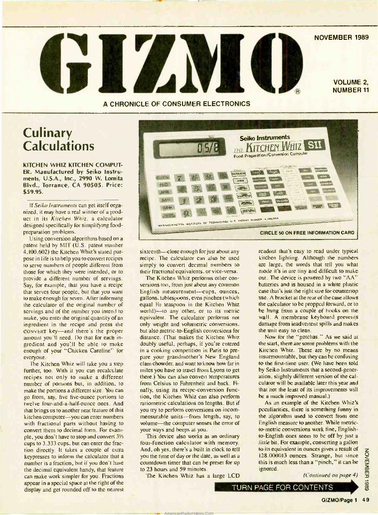
G 0 A CHRONICLE OF CONSUMER ELECTRONICS
NOVEMBER 1989
VOLUME 2,
NUMBER 11
Culinary Calculations KITCHEN WHIZ KITCHEN COMPUT- ER. Manufactured by Seiko Instru- ments, U.S.A., Inc., 2990 W. Lomita Blvd., Torrance, CA 90505. Price: $59.95.
If Seiko Instruments can get itself orga- nized, it may have a real winner of a prod- uct in its Kitchen Whiz, a calculator designed specifically for simplifying food - preparation problems.
Using conversion algorithms based on a patent held by MIT (U.S. patent number 4,100,602) the Kitchen Whiz's stated pur- pose in life is to help you to convert recipes to serve numbers of people different from those for which they were intended, or to provide a different number of servings. Say, for example, that you have a recipe that serves four people, but that you want to make enough for seven. After informing the calculator of the original number of servings and of the number you intend to make, you enter the original quantity of an ingredient in the recipe and press the CONVERT key -and there's the proper amount you'll need. Do that for each in- gredient and you;ll be able to make enough of your "Chicken Caroline" for everyone.
The Kitchen Whiz will take you a step further, too. With it you can recalculate recipes not only to make a different number of portions but, in addition, to make the portions a different size. You can go from, say, five five -ounce portions to twelve four -and -a- half -ounce ones. And that brings us to another neat feature of this kitchen computer -you can enter numbers with fractional parts without having to convert them to decimal form. For exam- ple, you don't have to stop and convert 3V3
cups to 3.333 cups, but can enter the frac- tion directly. It takes a couple of extra keypresses to inform the calculator that a number is a fraction, but if you don't have the decimal equivalent handy, that feature can make work simpler for you. Fractions appear in a special space at the right of the display and get rounded off to the nearest
Seiko Instruments
LbiLd>ñ il .l Food PreparationiConversion Compitar
EMI VIM` 1!1[ =T1 INK WOK 1 Ilia
TEA att4t&
Una
1lCi 1 loa votka "vir ">`.,
CIRCLE 50 ON FREE INFORMATION CARD
sixteenth -close enough for just about any recipe. The calculator can also be used simply to convert decimal numbers to their fractional equivalents, or vice- versa.
The Kitchen Whiz performs other con- versions too, from just about any common English measurement -cups, ounces, gallons, tablespoons, even pinches (which equal 1/42 teaspoon in the Kitchen Whiz world) -to any ' other, or to its metric equivalent. The calculator performs not only weight and volumetric conversions, but also metric -to- English conversions for distance. (That makes the Kitchen Whiz doubly useful, perhaps, if you're entered in a cooking competition in Paris to pre- pare your grandmother's New England clam chowder, and want to know how far in miles you have to travel from Lyons to get there.) You can also convert temperatures from Celsius to Fahrenheit and back. Fi- nally, using its recipe- conversion func- tion, the Kitchen Whiz can also perform ratiometric calculations on lengths. But if you try to perform conversions on incom- mensurable units -from length, say, to volume-the computer senses the error of your ways and beeps at you.
This device also works as an ordinary four -function calculator with memory. And, oh yes, there's a built in clock to tell you the time of day or the date, as well as a countdown timer that can be preset for up to 23 hours and 59 minutes.
The Kitchen Whiz has a large LCD
readout that's easy to read under typical kitchen lighting. Although the numbers are large, the words that tell you what mode it's in are tiny and difficult to make out. The device is powered by two "AA" batteries and is housed in a white plastic case that's just the right size for countertop use. A bracket at the rear of the case allows the calculator to be propped forward, or to be hung from a couple of hooks on the wall. A membrane keyboard prevelits damage from inadvertent spills and makes the unit easy to clean.
Now for the "gotchas." As we said at the start, there are some problems with the Kitchen Whiz. These are by no means insurmountable, but they can be confusing to the first -time user. (We have been told by Seiko Instruments that a second- gener- ation, slightly different version of the cal- culator will be available later this year and that'not the least of its improvements will be a much improved manual.)
As an example of the Kitchen Whiz's peculiarities, there is something funny in the algorithm used to convert from one English measure to another. While metric - to-metric conversions work fine, English - to- English ones seem to be off by just a little bit. For example, converting a gallon to its equivalent in ounces gives a result of 128.000013 ounces. Strange, but since this is much less than a "pinch," it can be ignored.
(Continued on page 4)
TURN PAGE FOR CONTENTS
GIZMO /Page 1 49
AmericanRadioHistory.Com
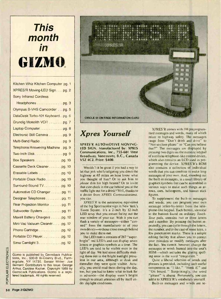
This month
in
GIZMO Kitchen Whiz Kitchen Computer pg. 1
XPRES'R Moving -LED Sign pg. 2
Sony Infrared Cordless
Headphones pg. 3
Olympus S -VHS Camcorder pg. 5
DataDesk Turbo -101 Keyboard pg. 6
Grundig Monolith VCR pg. 7
Laptop Computer pg. 8
Electronic Still Camera pg. 9
Multi -Band Radio pg. 9
Telephone Answering Machine pg. 9
Two -Inch Disk pg. 9
Box Speakers pg. 10
Cassette Deck Cleaner pg. 10
Erasable Labels . pg. 10
Portable Clock Radio pg. 10
Surround -Sound TV pg. 10
Automotive CD Changer pg. 11
Designer Telephones pg. 11
Rear Projection Monitor pg. 11
Subwoofer System pg. 11
Maxell Battery Chargers pg. 12
Mini -Vac Vacuum Cleaner pg. 12
Phono Cartridge pg. 12
Portable CD Player pg. 12
Sima Camlight 3 pg. 12
Gizmo is published by Gernsback Publica- tions, Inc.. 500 -B Bi- County Blvd., Farm- ingdale, NY 11735. Senior Writer: Joe Bernard. Contributors to this issue: George Arthur, Caroline Kaplan. Copyright 1989 by Gernsback Publications. Gizmo is a regis- tered trademark. All rights reserved.
50 Page 2 GIZMO
XPRES
CIRCLE 51 ON FREE INFORMATION CARD
Xpres Yourself XPRES'R AUTOMOTIVE MOVING - LED SIGN. Manufactured by: XPRES
Communications, Inc., 755 -601 West Broadway, Vancouver, B.C., Canada V5Z 4C2. Price: $400.
Wouldn't it be great if you had a way to let that jerk who's tailgating you down the highway at 65 miles an hour know what you thought of him? Or to ask him to please dim his high beams? Or to invite that cute chick in the car behind you at the traffic light out for a drink? Well, thanks to a device from XPRES Communications, you can.
XPRES'R is the automotive equivalent of the big Spectracolor sign in New York's Times Square. It's a 2 -inch by 12 -inch LED array that you mount facing out the rear window of your car. With it you can flash a variety of messages - either "can- ned" from the manufacturer or of your own device -to those close enough behind you to make them out.
The LED matrix consists of 287 "super - bright" red LED's and can display seven letters or graphics symbols at a time. The LED's are said to be visible even in the light of day. We had some difficulty mak- ing them out in the bright sunlight preva- lent in our area, although at dusk and thereafter they were quite visible. Actu- ally, you could read them during the day, too, but you had to know what to look for in advance -the display wasn't bright enough to attract attention all by itself un- der daylight conditions.
XPRES'R conies with 198 preprogram- med messages and words, many of which relate to highway safety. The messages range from "Don't drink and drive" to "Not so close please" to "Can you believe that ?" The messages are displayed by pressing two digits on the numeric keypad of a cellular -telephone -like control device, which also contains an LCD used in pro- gramming the device. XPRES'R's ROM also contains a collection of individual words that you can combine to make long messages of your own. And, rounding out the built -in messages, is a small library of graphics symbols that can be assembled in various ways to make such things as ar- rows, cars, helicopters, and human stick figures.
To supplement the built -in messages and words, you can program your own message letter -by- letter from the tele- phone -like keypad. Each button, identical to the buttons found on ordinary Touch - Tone pads, contains two or three letters and a number, By pressing the button re- peatedly, you can cycle through the letters, the number, and in the case of some keys, a
few punctuation marks. There is a simple editing facility that allows you to correct your mistakes or modify messages after the fact. You cannot, however, change the messages or words burned into the unit's ROM -which includes the glaring spell- ing error in the word "conjestion."
Quite a liberal selection of words and phrases is provided, including such useful components as "I like," -Honk if," and "On board." Surprisingly, the word "please" is absent. Fortunately, you can add it to XPRES'R's vocabulary yourself.
Built -in messages and words are se-
AmericanRadioHistory.Com
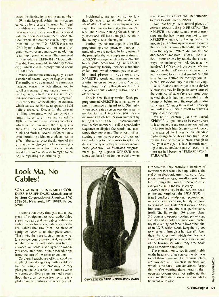
lected for display by pressing the number I -99 on the keypad. Additional words are called up by pressing "star-number" and "double -star- number" sequences. The messages you create yourself are accessed with the "pound- sign -number" combina- tion, where the number can be anything from "Ol" to "64." XPRES'R can store 1750 bytes (characters) of user -pro- grammed words and messages in addition to its preprogrammed ones. They are saved in non -volatile EEPROM (Electrically Erasable Programmable Read -Only Mem- ory), which can be reprogrammed about 10,000 times.
When you compose messages, you have a choice of several ways to display them. The attributes you can attach to a message include: SCROLL, which allows you to scroll a message of any length across the display; pop, which causes a seven -let- ter(s) -or -fewer word or message to "grow" from the bottom of the display up; and BIG,
which causes the display to appear in bold italic characters. Except for the case of scrolling messages, which can be of any length, screens, as they are called by XPRES, cannot exceed seven characters, which is the maximum the display can show at a time. Screens can be made to blink and flash at several different rates, even permitting a kind of crude animation effect. You can also set the duration of the display; your choices include running a
message from one to five times, or repeat- ing it for from five seconds to eight hours, or just repeating it continuously.
Incidentally, the unit consumes less than 100 mA in its standby mode, and about 700 mA when it's displaying a mes- sage. The manufacturer says that you can leave the display running for 48 hours in your car and still have enough juice left in the battery to start the engine.
Putting together messages is a lot like programming a computer, only not as in- timidating to the novice. In fact, many of the principles that you apply in creating an XPRES'R message are directly applicable to computer programming. XPRES'R's programming facility includes a function called LINK, which permits you to attach bits and pieces of your own and XPRES'R's words and messages to one another to create longer ones. You can bring along most, although not all, of a screen's attributes when you link it to an- other screen.
This is how linking works: Each pre- programmed XPRES'R item has, as we've seen, a number assigned to it. Similarly, when you create a screen you also assign a number to that. Using LINK, you create a message (which has its own number) by telling XPRES'R's 80C31 microcomputer brain which numbers to call in a particular sequence to display the words and mes- sages they represent. The process of as- signing a number to a piece of data and then referring to that number to get at the data is exactly what happens inside a com- puter program. For frustrated program- mers, putting together XPRES'R mes- sages can be a lot of fun, especially when
you use numbers to refer to other numbers to refer to still other numbers.
And that brings us to several pieces of advice about using XPRES'R. The XPRES'R instructions, and even a mes- sage on the box, warn you not to use XPRES'R when you're driving the car it's mounted in. Calling up a message requires that you enter a two- or three -digit number from the keypad. While you can do that one- handed, and even -after a little prac- tice- more-or -less by touch, there is al- ways the tendency to look down at the handset's LCD (which echoes what's go- ing on on the LED device facing out the rear window) to verify that you hit the right keys and are getting the message you ex- pected. Please don't try that while driving.
XPRES also cautions you that a device such as this may be illegal in some parts of the country. What we're even more con- cerned about is that the guy with his high beams on behind us at the stop light is also carrying a .22 under the seat of his pickup and will take it upon himself to deliver.a reply to our message.
We're not certain just how useful XPRES'R is-you have to be pretty close to it to make out the messages spelled out by its two -inch -high letters (for reference, we measured the letters on an interstate highway sign to be about a foot high). And by the time someone is close enough to read your message -at least in traffic mov- ing at any appreciable rate of speed -that message had better be "PLEASE DON'T TAILGATE."
Look Ma, No Cables! SONY MDR -IF5K INFRARED COR- DLESS HEADPHONES. Manufactured by: Sony Corporation of America, 9 W. 57th St., New York, NY 10019. Price: $200.
It seems that every time you add a new piece of equipment to your audio /video system you also add new cables: cables for audio, cables for video, cables for speak- ers, cables that run from one piece of equipment here to another piece there. That's why there are such things as wire- less remote controls -to cut down on the number of wires and cables you have to connect, and route, and maybe trip over as you encounter them in their meanderings from one part of the room to another.
Cordless headphones offer a good ex- ample of how doing away with a cable or two can simplify life. Not only do they give you one less cable to stumble over as you cross your living -room or media -room floor, they also free you from getting tan- gled up in that trailing cord where you sit.
CIRCLE 52 ON FREE INFORMATION CARD
Furthermore, they promise a freedom of movement that would be impossible at the end of an electronic umbilical cord. And, phones -of any variety -allow you to lis- ten to things that would otherwise drive everyone else in the house crazy.
Sony's new entry in the cordless -head- phone marketplace, the MDR -IF5K in- frared cordless headphone, provides not only cordless operation, but stylish good looks as well -a feature that seems to be as important in some circles as performance itself. The lightweight (98 grams, about 3'/ ounces), open -air -design phones are Meekly and curvily designed (and proba- bly have a drag coefficient lower than that of an RX -7, which would keep them glued to your ears through a hurricane!). Even their charging unit, which doubles as a stand when the phones are not in use and as the transmitter when they are, could pass as modern sculpture.
The phones themselves fit comfortably on the head and, after you learn which way to put them on-a number of visual clues are provided as to which is the front and which is the back -you can almost forget that you're wearing them. Again. their open -air design does not suffocate the ears, and they also allow outside sounds to be heard with ease.
GIZMO /Page 3 51
AmericanRadioHistory.Com
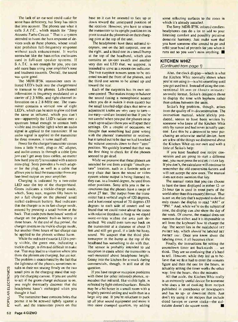
The lack of an ear -seal could make for some bass deficiency, but Sony has taken that into account. The phones use what it calls S.A.T.C., which stands for "Sony Acoustic Turbo Circuit." That is a system intended to boost the bass response of de- vices such as these phones, whose small size prohibits full- frequency response without such enhancement. It works somewhat like the bass -reflex enclosures used in full -size speaker systems. If S.A.T.C. is not enough for you, you can add more bass using your amplifier's tone and loudness controls. Overall, the sound was quite good.
The MDR -IF5K transmitter uses in- frared LED's built into the charger /stand to transmit to the phones. Left- channel information is frequency modulated on a carrier of 2.3 MHz, and right- channel in- formation on a 2.8 -MHz one. The trans- mitter contains a vertical row of eight LED's, which can be seen to glow red (not the same as infrared, which you can't see -apparently the LED's radiate over a spectrum broad enough to contain both visible and invisible light) when an audio signal is applied to the transmitter. If no audio signal is applied to the transmitter for three minutes, it turns itself off.
Power for the charger /transmitter comes from a little 9 -volt, plug -in AC adapter, and audio comes in through a cable (you just can't get away from cables, no matter how hard you try!) terminated with a stereo mini -plug. Sony provides a 1/4-inch adapt- er for the plug, as well as a cable that allows you to feed the transmitter from any line -level output on your amplifier.
Charging is indicated by a two -color LED near the top of the charger /stand. Green indicates a trickle- charge mode, which, Sony says, requires fifty hours to put a full charge on the phones' small nickel -cadmium battery. Red indicates that the charger is in its fast -charge mode, entered by pressing a small button at the back. That mode puts three hours' worth of charge on the phones' built -in battery in three hours. At the end of that period, the charger reverts to its trickle -charge mode, but another three hours of fast charge can be applied to the phones without harm.
While the red FAST -CHARGE LED is pret- ty visible, the green one, indicating a trickle charge, is dim and difficult to make out. That may lead to a situation where you think the phones aie charging, but are not. The problem is exacerbated by the fact that the lightness of the phones sometimes re- sults in their not seating firmly on the two small pins in the charging stand that sup- ply the charging current. If you are unable to tell if the green charge indicator is on, you might eventually discover that the headphone hasn't recharged when you thought it had.
The transmitter base contains holes that permit it to be screwed tightly against a wall, and the transmitter pivots on that
52 Page 4 /GIZMO
base so it can be oriented to face up or down toward the anticipated position of the receiver. However, you have to return the transmitter to its upright position on its pivot to make the phones sit on their charg- ing pins at the top of the unit.
The headphones have three infrared re- ceptors, one on the left earpiece, one on the right, and a third one in a small bump at the top of the headband, which also contains an ON -OFF switch and another very dim red LED that, we suppose, is intended to serve as a POWER ON indicator. The two earpiece sensors seem to be ori- ented toward the front of the phones, and the third one seems to be aimed up and toward the rear.
Each of the earpieces has its own vol- ume control. That makes it easy to balance the sound (using a monophonic source when you do it makes it even easier) but the small knurled -edge discs that serve as adjustment knobs are very easy to turn- too easy - and are located so that if you're not careful when you put the phones on or reach up to adjust them you will upset their settings. On a couple of occasions we thought that something had gone wrong with the phones' transmitter or receiver, but it turned out to be that we had knocked the volume controls down to their "zero" position. We quickly learned that that was the first thing to check for if the phones seemed to go dead.
While we presume that these phones are intended for use from a single "couch po- tato" location, such as a favorite sofa or easy chair that faces the sound or video system whose output is being listened to, they can, to a limited degree, be used from other positions. Sony tells you in the in- structions that the phones have a range of about 27 feet. The output from the trans- mitter has a vertical angle of 120 degrees, and a horizontal spread of 70 degrees (35 degrees to each side of center) and we found that we could move about the room with relative freedom as long as we stayed more -or -less within the area just de- scribed. We could even turn our back on the transmitter at a distance of about 15 feet and still get good, if a little bit hissy, sound. We suspect that the third pho- toreceptor in the bump at the top of the headband has something to do with that. The sensor is probably intended to aid reception in cases where the transmitter is wall- mounted above headphone height. Going into the kitchen for a snack during commercials, though, is still out of the question.
If you have range or reception problems with these (or other infrared) phones, re- member that infrared, like visible light, is reflected by light- colored surfaces. Results may be a bit better in a small room with a brightly painted ceiling and walls than in a large airy one. If you're reluctant to pack up all your sound equipment and move it into more cramped quarters, try adding
some reflecting surfaces to the room in which it's already installed.
The Sony MDR -IF5K infrared cordless headphones can do a lot to add to your listening comfort and possibly preserve domestic harmony. Just make sure that you have someone else around to go and refill your bowl of pretzels for you when it runs out so you won't miss anything.
KITCHEN WHIZ (Continued from page 9)
Also, the clock display -which is what the Kitchen Whiz normally shows when you're not using it -is a bit unsettling until you get used to it. Instead of using the con- ventional hh:mm:ss (hours:minutes: seconds) format, Seiko's designers chose to display the time with hyphens rather than colons between the units.
Seiko's big problem, though, arises from the quality of its documentation. The instruction manual, while slickly pro- duced, seems to have been written by someone who knew of the Kitchen Whiz only by rumor and had never actually used one. Lest this be a deterrent to your pur- chasing an otherwise useful device, here are a few of the things we discovered about the Kitchen Whiz on our own and with a little of Seiko's help:
If you have finished one recipe con- version and are going to start a different one, you must press the RECIPE CLEAR key_ If you don't, the calculator will continue to remember the old conversion factors and will not accept the new ones. The manual does not even mention that key.
The manual states that you can choose to have the time displayed in either 12- or 24 -hour (as is used in most parts of the world other than this country) format. That is not so; the key that's supposed to do that only causes the display to read "AM" or "PM. " And, while we're on the subject of time, the display can also show the day of the week. Of course, the manual does not mention that either, and it is impossible to tell from the keyboard how to change the day. The secret lies in the mislabeled SET
PM /SET key, which should be labeled SET
PM /SET DAY. Once you know about the labeling error, it all becomes clear.
Finally, the instructions for setting the countdown timer are backwards ... we think. They are so confusing that it's hard to tell. However, while they led us to be- lieve that we first had to enter the minutes figure and then the one for the hours, in actuality setting the timer works the other way: first the hours, then the minutes.
All that aside, the Kitchen Whiz really is an extremely useful device for someone who does a lot of cooking from recipes published in cookbooks or newspapers and has to up- or downsize them. Just don't try using it on recipes that include diced turnips or carrot sticks -the cal- culator doesn't do square roots.
AmericanRadioHistory.Com
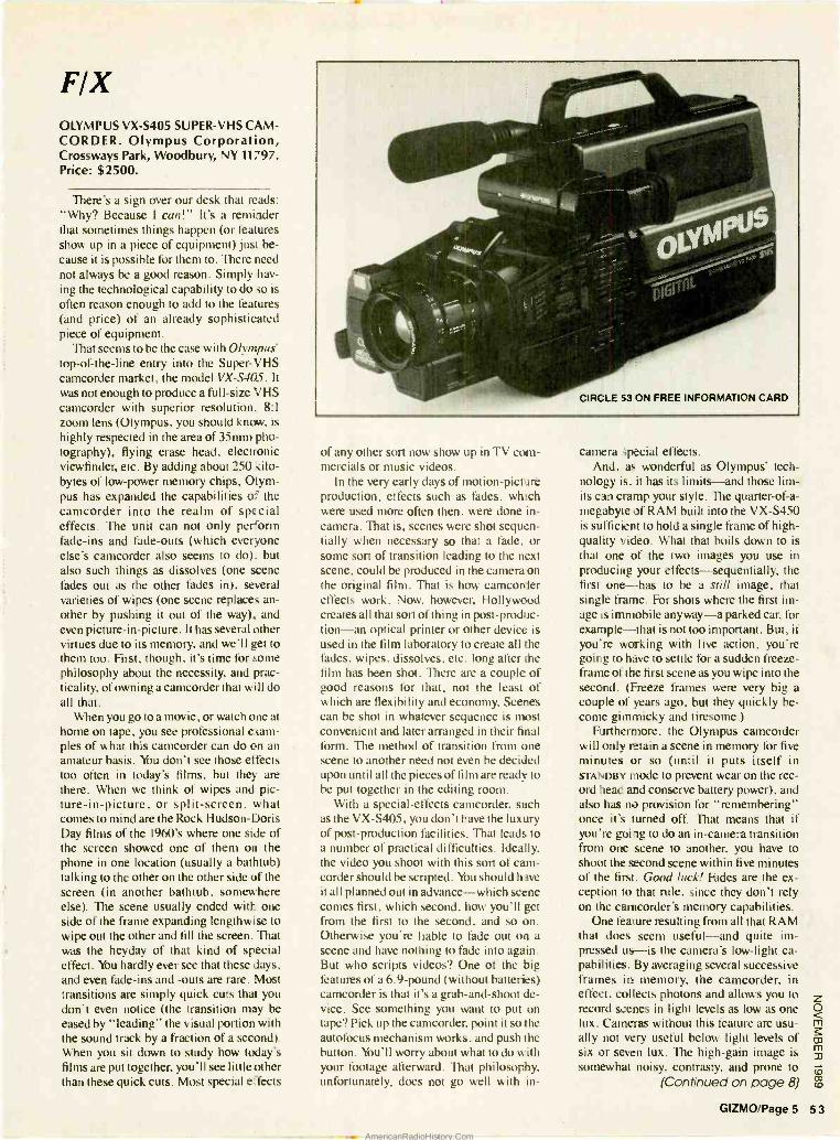
FIX OLYMPUS VX -S405 SUPER -VHS CAM- CORDER. Olympus Corporation, Crossways Park, Woodbury, NY 11797. Price: $2500.
There's a sign over our desk that reads: "Why? Because I can!" It's a reminder that sometimes things happen (or features show up in a piece of equipment) just be- cause it is possible for them to. There need not always be a good reason. Simply hav- ing the technological capability to do so is
often reason enough to add to the features (and price) of an already sophisticated piece of equipment.
That seems to be the case with Olympus' top -of -the -line entry into the Super -VHS camcorder market, the model VX -S405. It was not enough to produce a full -size VHS camcorder with superior resolution, 8:1
zoom lens (Olympus, you should know, is
highly respected in the area of 35mm pho- tography), flying erase head, electronic viewfinder, etc. By adding about 250 kilo- bytes of low -power memory chips, Olym- pus has expanded the capabilities of the camcorder into the realm of special effects. The unit can not only perform fade -ins and fade -outs (which everyone else's camcorder also seems to do). but also such things as dissolves (one scene fades out as the other fades in), several varieties of wipes (one scene replaces an- other by pushing it out of the way), and even picture -in- picture. It has several other virtues due to its memory, and we'll get to them too. First, though, it's time for some philosophy about the necessity, and prac- ticality, of owning a camcorder that will do all that.
When you go to a movie, or watch one at home on tape, you see professional exam- ples of what this camcorder can do on an amateur basis. You don't see those effects too often in today's films, but they are there. When we think of wipes and pic- ture-in- picture, or split -screen, what comes to mind are the Rock Hudson -Doris Day films of the 1960's where one side of the screen showed one of them on the phone in one location (usually a bathtub) talking to the other on the other side of the screen (in another bathtub, somewhere else). The scene usually ended with one side of the frame expanding lengthwise to wipe out the other and fill the screen. That was the heyday of that kind of special effect. You hardly ever see that these days, and even fade -ins and -outs are rare. Most transitions are simply quick cuts that you don't even notice (the transition may be eased by "leading" the visual portion with the sound track by a fraction of a second). When you sit down to study how today's films are put together, you'll see little other than these quick cuts. Most special effects
of any other sort now show up in TV com- mercials or music videos.
In the very early days of motion -picture production, effects such as fades, which were used more often then, were done in- camera. That is, scenes were shot sequen- tially when necessary so that a fade, or some sort of transition leading to the next scene, could be produced in the camera on the original film. That is how camcorder effects work. Now, however, Hollywood creates all that sort of thing in post- produc- tion -an optical printer or other device is used in the film laboratory to create all the fades, wipes, dissolves, etc. long after the film has been shot. There are a couple of good reasons for that, not the least of which are flexibility and economy. Scenes can be shot in whatever sequence is most convenient and later arranged in their final form. The method of transition from one scene to another need not even be decided upon until all the pieces of film are ready to be put together in the editing room.
With a special- effects camcorder, such as the VX -5405, you don't have the luxury of post- production facilities. That leads to a number of practical difficulties. Ideally, the video you shoot with this sort of cam- corder should be scripted. You should have it all planned out in advance -which scene comes first, which second, how you'll get from the first to the second, and so on. Otherwise you're liable to fade out on a scene and have nothing to fade into again. But who scripts videos? One of the big features of a 6.9 -pound (without batteries) camcorder is that it's a grab- and -shoot de- vice. See something you want to put on tape? Pick up the camcorder. point it so the autofocus mechanism works, and push the button. You'll worry about what to do with your footage afterward. That philosophy. unfortunately, does not go well with in-
camera special effects. And, as wonderful as Olympus' tech-
nology is, it has its limits -and those lim- its can cramp your style. The quarter -of -a- megabyte of RAM built into the VX -S450 is sufficient to hold a single frame of high - quality video. What that boils down to is that one of the two images you use in producing your effects -sequentially, the first one -has to be a still image, that single frame. For shots where the first im- age is immobile anyway -a parked car, for example -that is not too important. But, if you're working with live action, you're going to have to settle for a sudden freeze - frame of the first scene as you wipe into the second. (Freeze frames were very big a couple of years ago, but they quickly be- come gimmicky and tiresome.)
Furthermore, the Olympus camcorder will only retain a scene in memory for five minutes or so (until it puts itself in STANDBY mode to prevent wear on the rec- ord head and conserve battery power), and also has no provision for "remembering" once it's turned off. That means that if you're going to do an in- camera transition from one scene to another, you have to shoot the second scene within five minutes of the first. Good luck! Fades are ex- ception to that rule, since they don't rely on the camcorder's memory capabilities.
One feature resulting from all that RAM that does seem useful -and quite im- pressed us-is the camera's low -light ca- pabilities. By averaging several successive frames in memory, the camcorder, in effect, collects photons and allows you to record scenes in light levels as low as one lux. Cameras without this feature are usu- ally not very useful below light levels of six or seven lux. The high -gain image is somewhat noisy, contrasty, and prone to
(Continued on page 8)
GIZMO/Page 5 5 3
AmericanRadioHistory.Com
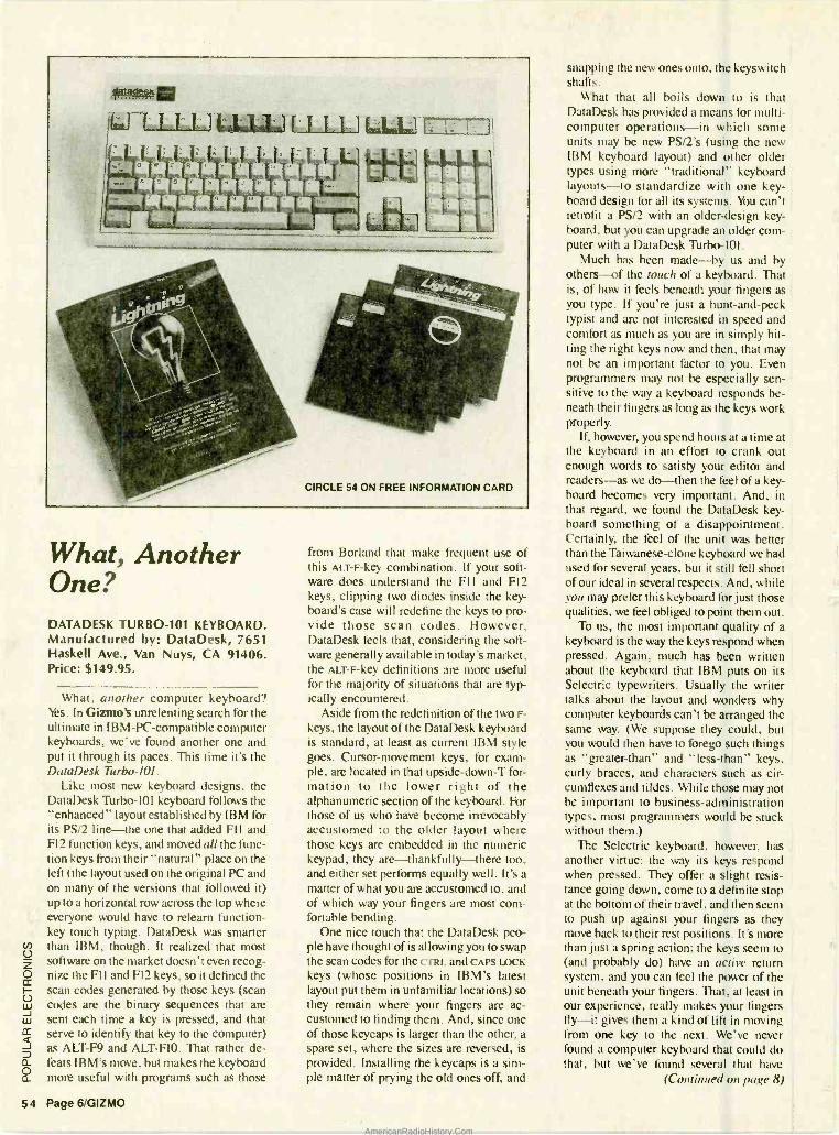
.,`0-t. all
ÌW [ I LLLLJ [ I I I
CIRCLE 54 ON FREE INFORMATION CARD
What, Another One? DATADESK TURBO -101 KEYBOARD. Manufactured by: DataDesk, 7651 Haskell Ave., Van Nuys, CA 91406. Price: $149.95.
What, another computer keyboard? Yes. In Gizmo's unrelenting search for the ultimate in IBM -PC- compatible computer keyboards, we've found another one and put it through its paces. This time it's the DataDesk Turbo -101.
Like most new keyboard designs. the DataDesk Turbo -l01 keyboard follows the "enhanced" layout established by IBM for its PS /2 line -the one that added FIl and FI2 function keys, and moved all the func- tion keys from their "natural" place on the left (the layout used on the original PC and on many of the versions that lìollowed it) up to a horizontal row across the top where everyone would have to relearn function - key touch typing. DataDesk was smarter than IBM, though. It realized that most software on the market doesn't even recog- nize the Fl I and F12 keys, so it defined the scan codes generated by those keys (scan codes are the binary sequences that are sent each time a key is pressed, and that serve to identify that key to the computer) as ALT -F9 and ALT -AO. That rather de- feats IBM's move, but makes the keyboard more useful with programs such as those
54 Page 6 /GIZMO
from Borland that make frequent use of this ALT -F -key combination. If your soft- ware does understand the Fl and F12 keys, clipping two diodes inside the key- board's case will redefine the keys to pro- vide those scan codes. However, DataDesk feels that, considering the soft- ware generally available in today's market, the ALT -F -key definitions are more useful for the majority of situations that are typ- ically encountered.
Aside from the redefinition of the two F-
keys , the layout of the DataDesk keyboard is standard, at least as current IBM style goes. Cursor -movement keys, for exam- ple, are located in that upside- down -T for- mation to the lower right of the alphanumeric section of the keyboard. For those of us who have become irrevocably accustomed to the older layout where those keys are embedded in the numeric keypad, they are- thankfully -there too, and either set performs equally well. It's a
matter of what you are accustomed to, and of which way your fingers are most com- fortable bending.
One nice touch that the DataDesk peo- ple have thought of is allowing you to swap the scan codes for the c rRL and CAPS LACK keys (whose positions in IBM's latest layout put them in unfamiliar locations) so they remain where your fingers are ac- customed to finding them. And, since one of those keycaps is larger than the other, a spare set, where the sizes are reversed, is
provided. Installing the keycaps is a sim- ple matter of prying the old ones off, and
snapping the new ones onto, the keyswitch shafts.
What that all boils down to is that DataDesk has provided a means for multi - computer operations -in which some ,,nits may be new PS /2's (using the new IBM keyboard layout) and other older types using more "traditional" keyboard layouts -to standardize with one key- board design for all its systems. You can't retrofit a PS /2 with an older -design key- board, but you can upgrade an older com- puter with a DataDesk Turbo -I01.
Much has been made -by us and by others -of the touch of a keyboard. That is, of how it feels beneath your fingers as you type. If you're just a hunt - and -peck typist and are not interested in speed and comfort as much as you are in simply hit- ting the right keys now and then, that may not be an important factor to you. Even programmers may not be especially sen- sitive to the way a keyboard responds be- neath their fingers as long as the keys work properly.
If, however, you spend hours at a time at the keyboard in an effort to crank out enough words to satisfy your editor and readers -as we do-then the feel of a key- board becomes very important. And, in that regard, we found the DataDesk key- board something of a disappointment. Certainly, the feel of the unit was better than the Taiwanese -clone keyboard we had used for several years, but it still fell short of our ideal in several respects. And, while you may prefer this keyboard for just those qualities, we feel obliged to point them out.
To us, the most important quality of a keyboard is the way the keys respond when pressed. Again, much has been written about the keyboard that IBM puts on its Selectric typewriters. Usually the writer talks about the layout and wonders why computer keyboards can't be arranged the same way. (We suppose they could, but you would then have to forego such things as "greater- than" and "less- than" keys, curly braces, and characters such as cir- cumflexes and tildes. While those may not be important to business- administration types, most programmers would be stuck without them.)
The Selectric keyboard, however, has another virtue: the way its keys respond when pressed. They offer a slight resis- tance going down, come to a definite stop at the bottom of their travel, and then seem to push up against your fingers as they move back to their rest positions. It's more than just a spring action; the keys seem to (and probably do) have an active return system, and you can feel the power of the unit beneath your fingers. That, at least in our experience, really makes your fingers fly -it gives them a kind of lift in moving from one key to the next. We've never found a computer keyboard that could do that, but we've found several that have
(Continued on page 8)
AmericanRadioHistory.Com
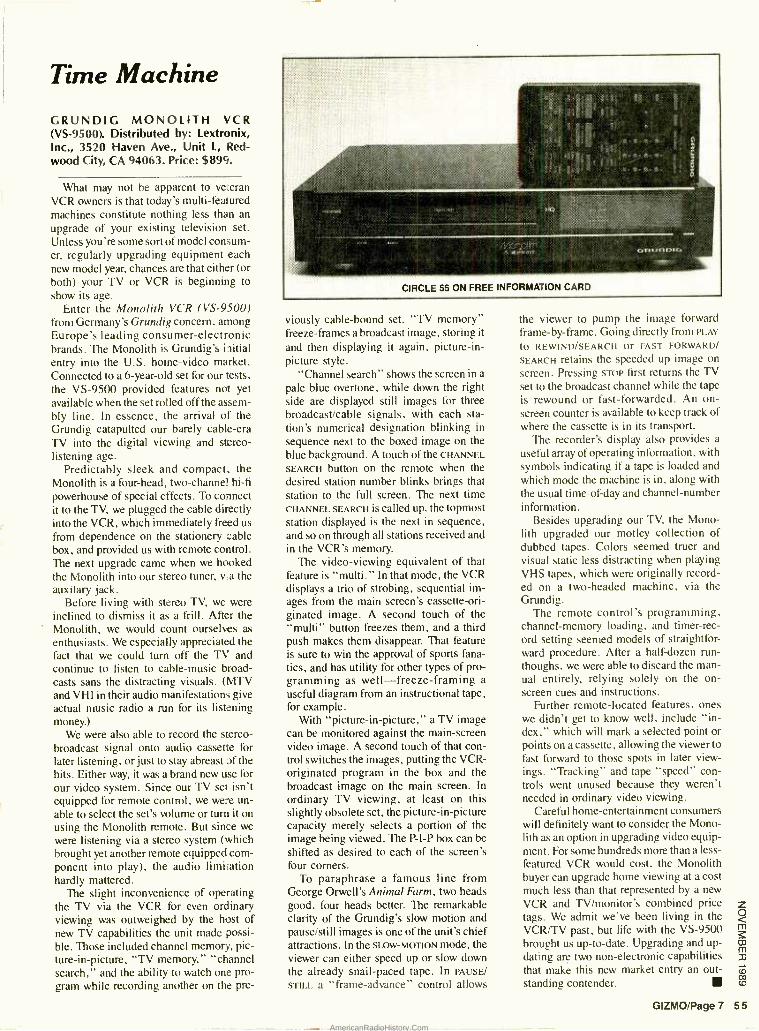
Time Machine
GRUNDIG MONOLITH VCR (VS- 9500). Distributed by: Lextronix, Inc., 3520 Haven Ave., Unit L, Red- wood City, CA 94063. Price: $899.
What may not be apparent to veteran VCR owners is that today's multi -featured machines constitute nothing less than an upgrade of your existing television set. Unless you're some sort of model consum- er, regularly upgrading equipment each new model year, chances are that either (or both) your TV or VCR is beginning to show its age.
Enter the Monolith VCR (VS -9500) from Germany's Grundig concern, among Europe's leading consumer -electronic brands. The Monolith is Grundig's iitial entry into the U.S. home -video market. Connected to a 6- year -old set for our tests, the VS -9500 provided features not yet available when the set rolled off the assem- bly line. In essence, the arrival of the Grundig catapulted our barely cable -era TV into the digital viewing and stereo - listening age.
Predictably sleek and compact, the Monolith is a four -head, two -channel hi -fi
powerhouse of special effects. To connect it to the TV, we plugged the cable directly into the VCR, which immediately freed us from dependence on the stationery cable box, and provided us with remote control. The next upgrade came when we hooked the Monolith into our stereo tuner, via the auxilary jack.
Before living with stereo TV, we were inclined to dismiss it as a frill. After the Monolith, we would count ourselves as enthusiasts. We especially appreciated the fact that we could turn off the TV and continue to listen to cable -music broad- casts sans the distracting visuals. (MTV and VHI in their audio manifestations give actual music radio a run for its listening money.)
We were also able to record the stereo - broadcast signal onto audio cassette for later listening, or just to stay abreast of the hits. Either way, it was a brand new use for our video system. Since our TV set isn't equipped for remote control, we were un- able to select the set's volume or turn it on using the Monolith remote. But since we were listening via a stereo system (which brought yet another remote equipped com- ponent into play), the audio limitation hardly mattered.
The slight inconvenience of operating the TV via the VCR for even ordinary viewing was outweighed by the host of new TV capabilities the unit made possi- ble. Those included channel memory, pic- ture-in- picture, "TV memory," "channel search," and the ability to watch one pro- gram while recording another on the pre-
viously cable -bound set. "TV memory" freeze -frames a broadcast image, storing it
and then displaying it again, picture -in- picture style.
"Channel search" shows the screen in a
pale blue overtone, while down the right side are displayed still images for three broadcast /cable signals, with each sta- tion's numerical designation blinking in
sequence next to the boxed image on the blue background. A touch of the CHANNEL
SEARCH button on the remote when the desired station number blinks brings that station to the full screen. The next time CHANNEL SEARCH IS called up, the topmost station displayed is the next in sequence, and so on through all stations received and in the VCR's memory.
The video- viewing equivalent of that feature is "multi." In that mode, the VCR displays a trio of strobing, sequential im- ages from the main screen's cassette -ori- ginated image. A second touch of the "multi" button freezes them, and a third push makes them disappear. That feature is sure to win the approval of sports fana- tics, and has utility for other types of pro- gramming as well- freeze -framing a
useful diagram from an instructional tape, for example.
With "picture-in- picture," a TV image can be monitored against the main -screen video image. A second touch of that con- trol switches the images, putting the VCR - originated program in the box and the broadcast image on the main screen. In ordinary TV viewing, at least on this slightly obsolete set, the picture-in- picture capacity merely selects a portion of the image being viewed. The P -I -P box can be shifted as desired to each of the screen's four corners.
To paraphrase a famous line from George Orwell's Animal Farm, two heads good, four heads better. The remarkable clarity of the Grundig's slow motion and pause /still images is one of the unit's chief attractions. In the SLOW- MOTION mode, the viewer can either speed up or slow down the already snail -paced tape. In PAUSE/
STILL a "frame- advance" control allows
the viewer to pump the image forward frame -by- frame. Going directly from PLAY
to REWIND /SEARCH or FAST FORWARD/
SEARCH retains the speeded up image on screen. Pressing sToP first returns the TV set to the broadcast channel while the tape is rewound or fast -forwarded. An on- screen counter is available to keep track of where the cassette is in its transport.
The recorder's display also provides a
useful array of operating information, with symbols indicating if a tape is loaded and which mode the machine is in, along with the usual time -of -day and channel- number information.
Besides upgrading our TV, the Mono- lith upgraded our motley collection of dubbed tapes. Colors seemed truer and visual static less distracting when playing VHS tapes, which were originally record- ed on a two- headed machine, via the Grundig.
The remote control's programming, channel -memory loading, and timer -rec- ord setting seemed models of straightfor- ward procedure. After a half -dozen run - thoughs, we were able to discard the man- ual entirely, relying solely on the on- screen cues and instructions.
Further remote- located features, ones we didn't get to know well, include "in- dex," which will mark a selected point or points on a cassette, allowing the viewer to fast forward to those spots in later view - ings. "Tracking" and tape "speed" con- trols went unused because they weren't needed in ordinary video viewing.
Careful home -entertainment consumers will definitely want to consider the Mono- lith as an option in upgrading video equip- ment. For some hundreds more than a less - featured VCR would cost, the Monolith buyer can upgrade home viewing at a cost much less than that represented by a new VCR and TV /monitor's combined price tags. We admit we've been living in the VCR/TV past, but life with the VS -9500 brought us up -to -date. Upgrading and up- dating are two non -electronic capabilities that make this new market entry an out- standing contender.
GIZMO/Page 7 5 5
AmericanRadioHistory.Com
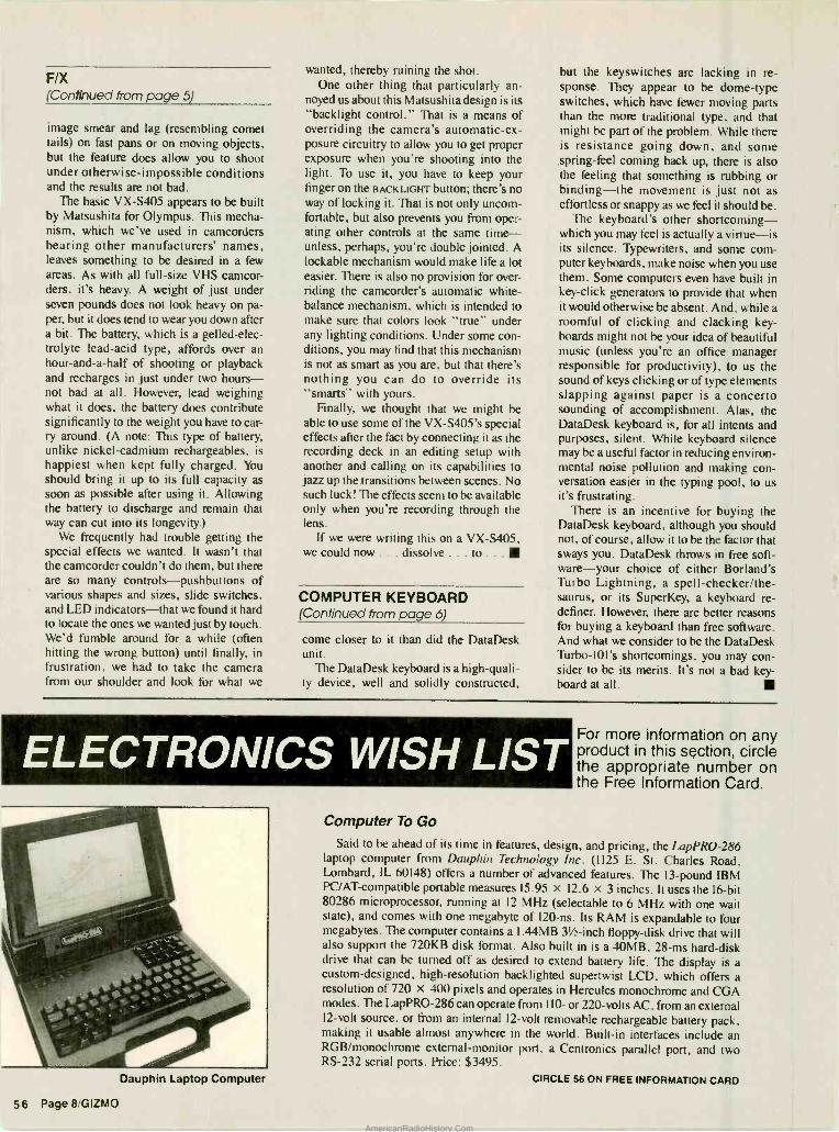
F/X (Continued from page 5)
image smear and lag (resembling comet tails) on fast pans or on moving objects, but the feature does allow you to shoot under otherwise- impossible conditions and the results are not bad.
The basic VX -S405 appears to be built by Matsushita for Olympus. This mecha- nism, which we've used in camcorders bearing other manufacturers' names, leaves something to be desired in a few areas. As with all full -size VHS camcor- ders, it's heavy. A weight of just under seven pounds does not look heavy on pa- per, but it does tend to wear you down after a bit. The battery, which is a gelled -elec- trolyte lead -acid type, affords over an hour -and -a -half of shooting or playback and recharges in just under two hours - not bad at all. However, lead weighing what it does, the battery does contribute significantly to the weight you have to car- ry around. (A note: This type of battery, unlike nickel -cadmium rechargeables, is happiest when kept fully charged. You should bring it up to its full capacity as soon as possible after using it. Allowing the battery to discharge and remain that way can cut into its longevity.)
We frequently had trouble getting the special effects we wanted. It wasn't that the camcorder couldn't do them, but there are so many controls- pushbuttons of various shapes and sizes, slide switches, and LED indicators -that we found it hard to locate the ones we wanted just by touch. We'd fumble around for a while (often hitting the wrong button) until finally, in frustration, we had to take the camera from our shoulder and look for what we
wanted, thereby ruining the shot. One other thing that particularly an-
noyed us about this Matsushita design is its "backlight control." That is a means of overriding the camera's automatic -ex- posure circuitry to allow you to get proper exposure when you're shooting into the light. To use it, you have to keep your finger on the BACKLIGHT button; there's no way of locking it. That is not only uncom- fortable, but also prevents you from oper- ating other controls at the same time - unless, perhaps, you're double jointed. A lockable mechanism would make life a lot easier. There is also no provision for over- riding the camcorder's automatic white - balance mechanism, which is intended to make sure that colors look "true" under any lighting conditions. Under some con- ditions, you may find that this mechanism is not as smart as you are, but that there's nothing you can do to override its "smarts" with yours.
Finally, we thought that we might be able to use some of the VX- S405's special effects after the fact by connecting it as the recording deck in an editing setup with another and calling on its capabilities to jazz up the transitions between scenes. No such luck! The effects seem to be available only when you're recording through the lens.
If we were writing this on a VX -S405, w e could now ... dissolve ... to ...
COMPUTER KEYBOARD (Continued from page 6)
come closer to it than did the DataDesk unit.
The DataDesk keyboard is a high- quali- ty device, well and solidly constructed,
but the keyswitches are lacking in re- sponse. They appear to be dome -type switches, which have fewer moving parts than the more traditional type, and that might be part of the problem. While there is resistance going down, and some spring -feel coming back up, there is also the feeling that something is rubbing or binding -the movement is just not as effortless or snappy as we feel it should be.
The keyboard's other shortcoming - which you may feel is actually a virtue -is its silence. Typewriters, and some com- puter keyboards, make noise when you use them. Some computers even have built in key -click generators to provide that when it would otherwise be absent. And, while a roomful of clicking and clacking key- boards might not be your idea of beautiful music (unless you're an office manager responsible for productivity), to us the sound of keys clicking or of type elements slapping against paper is a concerto sounding of accomplishment. Alas, the DataDesk keyboard is, for all intents and purposes, silent. While keyboard silence may be a useful factor in reducing environ- mental noise pollution and making con- versation easier in the typing pool, to us it's frustrating.
There is an incentive for buying the DataDesk keyboard, although you should not, of course, allow it to be the factor that sways you. DataDesk throws in free soft- ware -your choice of either Borland's Turbo Lightning, a spell- checker /the- saurus, or its SuperKey, a keyboard re- definer. However, there are better reasons for buying a keyboard than free software. And what we consider to be the DataDesk Turbo -101's shortcomings, you may con- sider to be its merits. It's not a bad key- board at all.
ELECTRONICS WISH LIST
Dauphin Laptop Computer
56 Page 8 GIZMO
For more information on any product in this section, circle the appropriate number on the Free Information Card.
Computer To Go
Said to be ahead of its time in features, design, and pricing, the LapPRO -286 laptop computer from Dauphin Technology Inc. (1125 E. St. Charles Road, Lombard, IL 60148) offers a number of advanced features. The 13 -pound IBM PC /AT- compatible portable measures 15.95 x 12.6 x 3 inches. It uses the 16 -bit 80286 microprocessor, running at 12 MHz (selectable to 6 MHz with one wait state), and comes with one megabyte of 120 -ns. Its RAM is expandable to four megabytes. The computer contains a 1.44MB 31/2-inch floppy -disk drive that will also support the 720KB disk format. Also built in is a 40MB, 28 -ms hard -disk drive that can be turned off as desired to extend battery life. The display is a custom -designed, high- resolution backlighted supertwist LCD, which offers a resolution of 720 x 400 pixels and operates in Hercules monochrome and CGA modes. The LapPRO -286 can operate from 110- or 220 -volts AC, from an external 12 -volt source, or from an internal 12 -volt removable rechargeable battery pack, making it usable almost anywhere in the world. Built -in interfaces include an RGB /monochrome external -monitor port. a Centronics parallel port, and two RS -232 serial ports. Price: $3495.
CIRCLE 56 ON FREE INFORMATION CARD
AmericanRadioHistory.Com
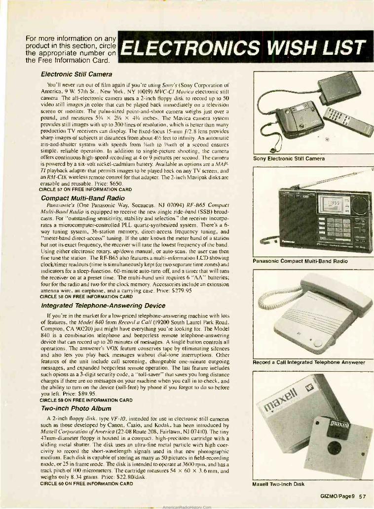
For more information on any product in this section, circle the appropriate number on the Free Information Card.
ELECTRONICS WISH LIST Electronic Still Camera
You'll never run out of film again if you're using Sony's (Sony Corporation of America, 9 W. 57th St., New York, NY 10019) MVC -CI Mavica electronic still camera. The all- electronic camera uses a 2 -inch floppy disk to record up to 50 video still images in color that can be played back immediately on a television screen or monitor. The palm -sized point- and -shoot camera weighs just over a pound, and measures 51/4 x 21/4 x 4' inches. The Mavica camera system provides still images with up to 300 lines of resolution, which is better than many production TV receivers can display. The fixed -focus 15 -mm f/2.8 lens provides sharp images of subjects at distances from about 41/2 feet to infinity. An automatic iris -and -shutter system with speeds from 1/60th to 1/400th of a second ensures simple, reliable operation. In addition to single -picture shooting, the camera offers continuous high -speed recording at 4 or 9 pictures per second. The camera is powered by a six -volt nickel -cadmium battery. Available as options are a MAP - TI playback adapter that permits images to be played back on any TV screen, and an RM -CIK wireless remote control for that adapter. The 2 -inch Mavipak disks are erasable and reusable. Price: $650.
CIRCLE 57 ON FREE INFORMATION CARD
Compact Multi -Band Radio Panasonic's (One Panasonic Way, Secaucus, NJ 07094) RF -B65 Compact
Multi -Band Radio is equipped to receive the new single side -band (SSB) broad- casts. For "outstanding sensitivity, stability and selection" the receiver incorpo- rates a microcomputer -controlled PLL quartz- synthesized system. There's a 6- way tuning system, 36- station memory, direct -access frequency tuning, and "meter -band direct -access" tuning. If the user knows the meter band of a station but not its exact frequency, the receiver will tune the lowest frequency of the band. Using either electronic rotary, up /down manual, or auto -scan, the user can then fine tune the station. The RF -B65 also features a multi -information LCD showing clock/timer readouts (time is simultaneously kept for two separate time zones) and indicators for a sleep- function, 60- minute auto -turn-off, and a timer that will turn the receiver on at a preset time. The multi -band unit requires 6 "AA" batteries; four for the radio and two for the clock memory. Accessories include an extension antenna wire, an earphone, and a carrying case. Price: $279.95 CIRCLE 58 ON FREE INFORMATION CARD
Integrated Telephone -Answering Device
If you're in the market for a low -priced telephone- answering machine with lots of features, the Model 840 from Record a Call (19200 South Laurel Park Road, Compton, CA 90220) just might have everything you're looking for. The Model 840 is a combination telephone and beeperless remote telephone -answering device that can record up to 20 minutes of messages. A single button controls all operations. The answerer's VOX feature conserves tape by eliminating silences and also lets you play back messages without dial -tone interruptions. Other features of the unit include call screening, changeable one -minute outgoing messages, and expanded beeperless remote operation. The last feature includes such opions as a 3 -digit security code, a "toll- saver" that saves you long distance charges if there are no messages on your machine when you call in to check, and the ability to turn on the device (toll -free) by phone if you forgot to do so before you left. Price: $89.95.
CIRCLE 59 ON FREE INFORMATION CARD
Two -inch Photo Album A 2 -inch floppy disk, type VF -10, intended for use in electronic still cameras
such as those developed by Canon, Casio, and Kodak, has been introduced by Maxell Corporation of America (22 -08 Route 208, Fairlawn, NJ 07410). The tiny 47mm- diameter floppy is housed in a compact, high -precision cartridge with a sliding metal shutter. The disk uses an ultra -fine metal particle with high coer- civity to record the short- wavelength signals used in that new photographic medium. Each disk is capable of storing as many as 50 pictures in field -recording mode, or 25 in frame mode. The disk is intended to operate at 3600 rpm, and has a track pitch of 100 micrometers. The cartridge measures 54 x 60 x 3.6 mm, and weighs only 8.34 grams. Price: $22.80 /disk. CIRCLE 60 ON FREE INFORMATION CARD
Sony Electronic Still Camera
Panasonic Compact Multi -Band Radio
Record a Call Integrated Telephone Answerer
Maxell Two -Inch Disk
GIZMO Page9 57
AmericanRadioHistory.Com
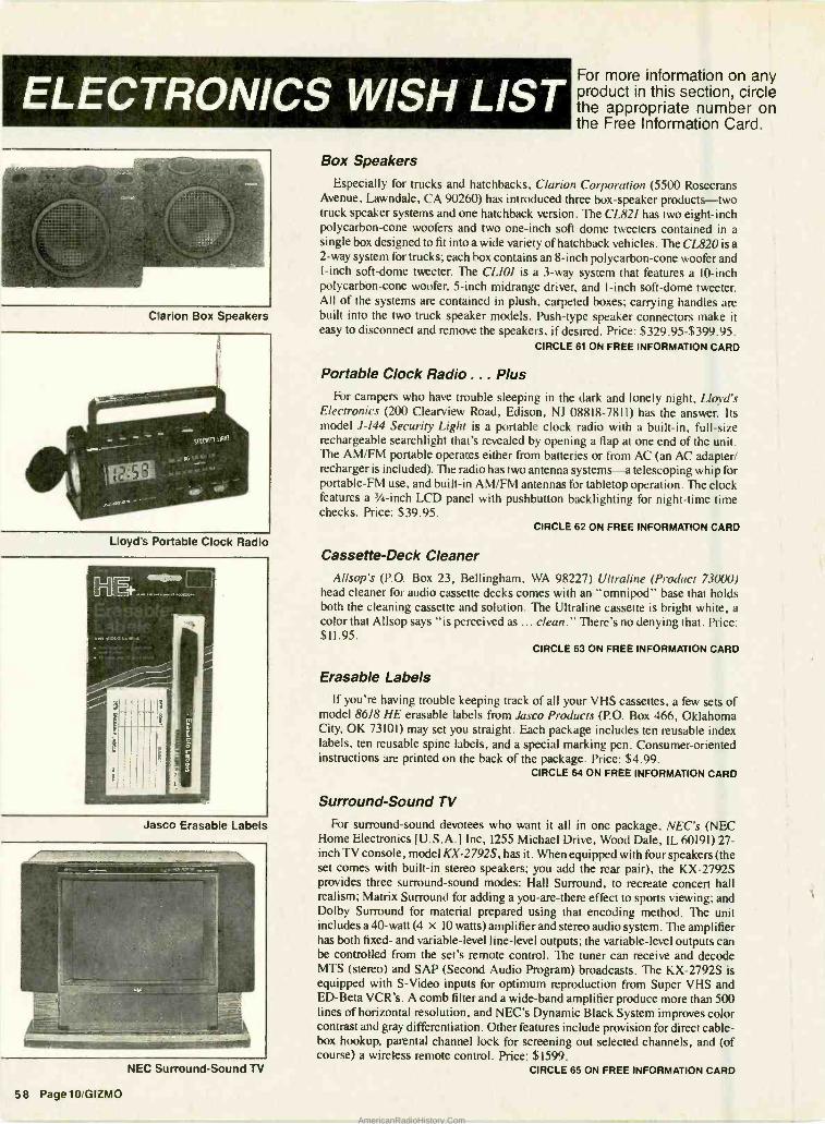
ELECTRONICS WISH LIST
Clarion Box Speakers
Lloyd's Portable Clock Radio
Jasco Erasable Labels
NEC Surround -Sound TV
58 Page10 GIZMO
For more information on any product in this section, circle the appropriate number on the Free Information Card.
Box Speakers Especially for trucks and hatchbacks, Clarion Corporation (5500 Rosecrans
Avenue, Lawndale, CA 90260) has introduced three box- speaker products -two truck speaker systems and one hatchback version. The CL821 has two eight -inch polycarbon -cone woofers and two one -inch soft dome tweeters contained in a single box designed to fit into a wide variety of hatchback vehicles. The CL820 is a 2 -way system for trucks; each box contains an 8 -inch polycarbon -cone woofer and 1 -inch soft -dome tweeter. The CL101 is a 3 -way system that features a 10 -inch polycarbon -cone woofer, 5 -inch midrange driver, and 1 -inch soft -dome tweeter. All of the systems are contained in plush, carpeted boxes; carrying handles are built into the two truck speaker models. Push -type speaker connectors make it easy to disconnect and remove the speakers, if desired. Price: $329.95- $399.95.
CIRCLE 61 ON FREE INFORMATION CARD
Portable Clock Radio ... Plus For campers who have trouble sleeping in the dark and lonely night, Lloyd's
Electronics (200 Clearview Road, Edison, NJ 08818 -7811) has the answer. Its model J -144 Security Light is a portable clock radio with a built -in, full -size rechargeable searchlight that's revealed by opening a flap at one end of the unit. The AM /FM portable operates either from batteries or from AC (an AC adapter/ recharger is included). The radio has two antenna systems -a telescoping whip for portable -FM use, and built -in AM /FM antennas for tabletop operation. The clock features a 3/4 -inch LCD panel with pushbutton backlighting for night -time time checks. Price: $39.95.
CIRCLE 62 ON FREE INFORMATION CARD
Cassette -Deck Cleaner Allsop's (P.O. Box 23, Bellingham, WA 98227) Ultraline (Product 73000)
head cleaner for audio cassette decks comes with an "omnipod" base that holds both the cleaning cassette and solution. The Ultraline cassette is bright white, a color that Allsop says "is perceived as ... clean." There's no denying that. Price: $11.95.
CIRCLE 63 ON FREE INFORMATION CARD
Erasable Labels
If you're having trouble keeping track of all your VHS cassettes, a few sets of model 8618 HE erasable labels from Jasco Products (P.O. Box 466, Oklahoma City, OK 73101) may set you straight. Each package includes ten reusable index labels, ten reusable spine labels, and a special marking pen. Consumer -oriented instructions are printed on the back of the package. Price: $4.99.
CIRCLE 64 ON FREE INFORMATION CARD
Surround -Sound TV
For surround -sound devotees who want it all in one package, NEC's (NEC Home Electronics [U.S.A.] Inc, 1255 Michael Drive, Wood Dale, IL 60191) 27- inch TV console, model KX- 2792S, has it. When equipped with four speakers (the set comes with built -in stereo speakers; you add the rear pair), the KX -2792S provides three surround -sound modes: Hall Surround, to recreate concert hall realism; Matrix Surround for adding a you -are -there effect to sports viewing; and Dolby Surround for material prepared using that encoding method. The unit includes a 40 -watt (4 x 10 watts) amplifier and stereo audio system. The amplifier has both fixed- and variable -level line -level outputs; the variable -level outputs can be controlled from the set's remote control. The tuner can receive and decode MTS (stereo) and SAP (Second Audio Program) broadcasts. The KX -2792S is equipped with S -Video inputs for optimum reproduction from Super VHS and ED -Beta VCR's. A comb filter and a wide -band amplifier produce more than 500 lines of horizontal resolution, and NEC's Dynamic Black System improves color contrast and gray differentiation. Other features include provision for direct cable - box hookup, parental channel lock for screening out selected channels, and (of course) a wireless remote control. Price: $1599.
CIRCLE 65 ON FREE INFORMATION CARD
AmericanRadioHistory.Com
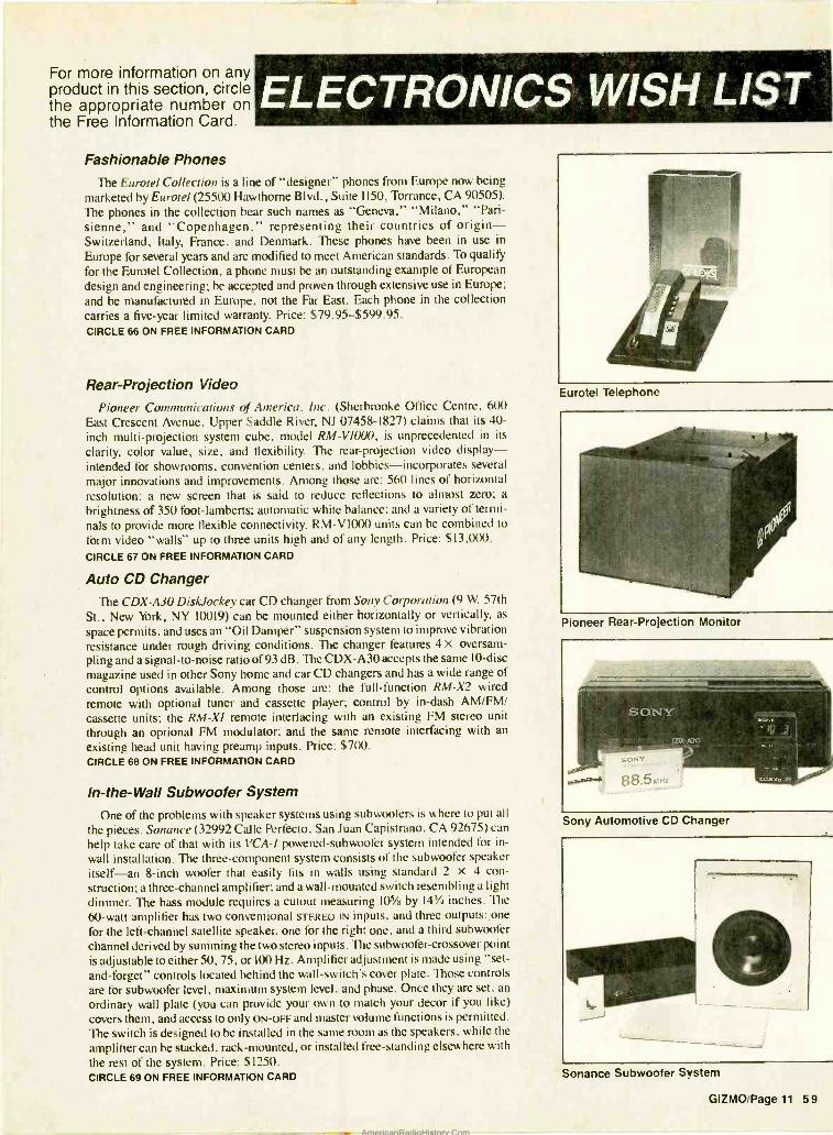
For more information on any product in this section, circle the appropriate number on the Free Information Card.
ELECTRONICS WISH LIST Fashionable Phones
The Eurotel Collection is a line of "designer" phones from Europe now being marketed by Eurotel (25500 Hawthorne Blvd., Suite 1150, Torrance, CA 90505). The phones in the collection bear such names as "Geneva," "Milano," "Pari- sienne," and "Copenhagen," representing their countries of origin - Switzerland, Italy, France, and Denmark. These phones have been in use in
Europe for several years and are modified to meet American standards. To qualify for the Eurotel Collection, a phone must be an outstanding example of European design and engineering; he accepted and proven through extensive use in Europe; and be manufactured in Europe, not the Far East. Each phone in the collection carries a five -year limited warranty. Price: $79.95 $599.95. CIRCLE 66 ON FREE INFORMATION CARD
Rear -Projection Video
Pioneer Communications of America, Inc. (Sherbrooke Office Centre, 600
East Crescent Avenue, Upper Saddle River, NJ 07458 -1827) claims that its 40- inch multi -projection system cube, model RM- VI000, is unprecedented in its
clarity, color value, size, and flexibility. The rear -projection video display - intended for showrooms, convention centers, and lobbies- incorporates several
major innovations and improvements. Among those are: 560 lines of horizontal resolution; a new screen that is said to reduce reflections to almost zero; a
brightness of 350 foot -lamberts; automatic white balance; and a variety of termi- nals to provide more flexible connectivity. RM -V 1000 units can be combined to form video "walls" up to three units high and of any length. Price: $13,000. CIRCLE 67 ON FREE INFORMATION CARD
Auto CD Changer The CDX -A30 DiskJockey car CD changer from Sony Corporation (9 W. 57th
St., New York, NY 10019) can be mounted either horizontally or vertically, as
space permits, and uses an "Oil Damper" suspension system to improve vibration resistance under rough driving conditions. The changer features 4 x oversam- pling and a signal -to -noise ratio of 93 dB. The CDX -A30 accepts the same 10 -disc magazine used in other Sony home and car CD changers and has a wide range of control options available. Among those are: the full- function RM -X2 wired
remote with optional tuner and cassette player; control by in -dash AM /FM/ cassette units; the RM -XI remote interfacing with an existing FM stereo unit
through an optional FM modulator; and the same remote interfacing with an
existing head unit having preamp inputs. Price: $700. CIRCLE 68 ON FREE INFORMATION CARD
!n- the -Wall Subwoofer System
One of the problems with speaker systems using subwoofers is where to put all
the pieces. Sonance (32992 Cal le Perfecto, San Juan Capistrano, CA 92675) can help take care of that with its VCA -I powered -subwoofer system intended for in-
wall installation. The three -component system consists of the subwoofer speaker itself -an 8 -inch woofer that easily fits in walls using standard 2 x 4 con- struction; a three - channel amplifier; and a wall- mounted switch resembling a light
dimmer. The bass module requires a cutout measuring 105/8 by 141/4 inches. The
60 -watt amplifier has two conventional STEREO IN inputs, and three outputs: one
for the left- channel satellite speaker, one for the right one, and a third subwoofer channel derived by summing the two stereo inputs. The subwoofer -crossover point is adjustable to either 50, 75, or 100 Hz. Amplifier adjustment is made using "set - and- forget" controls located behind the wall -switch's cover plate. Those controls are for subwoofer level, maximum system level, and phase. Once they are set, an
ordinary wall plate (you can provide your own to match your decor if you like) covers them, and access to only ON -OFF and master volume functions is permitted. The switch is designed to be installed in the same room as the speakers, while the
amplifier can be stacked, rack- mounted, or installed free -standing elsewhere with
the rest of the system. Price: $1250. CIRCLE 69 ON FREE INFORMATION CARD
Eurotel Telephone
Pioneer Rear -Projection Monitor
Sony Automotive CD Changer
Sonance Subwoofer System
GIZMO Page 11 59
AmericanRadioHistory.Com
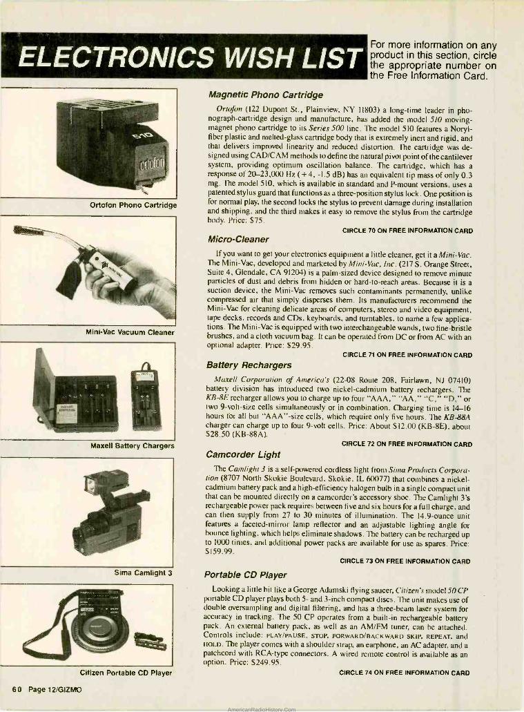
ELECTRONICS WISH LIST
Ortofon Phono Cartridge
Mini -Vac Vacuum Cleaner
Maxell Battery Chargers
Sima Camlight 3
Citizen Portable CD Player
60 Page 12 /GIZMO
For more information on any product in this section, circle the appropriate number on the Free Information Card.
Magnetic Phono Cartridge Ortofon (122 Dupont St., Plainview, NY 11803) a long -time leader in pho-
nograph- cartridge design and manufacture, has added the model 510 moving - magnet phono cartridge to its Series 500 line. The model 510 features a Noryl- fiber plastic and melted -glass cartridge body that is extremely inert and rigid, and that delivers improved linearity and reduced distortion. The cartridge was de- signed using CAD /CAM methods to define the natural pivot point of the cantilever system, providing optimum oscillation balance. The cartridge, which has a response of 20- 23,000 Hz ( +4, -1.5 dB) has an equivalent tip mass of only 0.3 mg. The model 510, which is available in standard and P -mount versions, uses a patented stylus guard that functions as a three -position stylus lock. One position is for normal play, the second locks the stylus to prevent damage during installation and shipping, and the third makes it easy to remove the stylus from the cartridge body. Price: $75.
CIRCLE 70 ON FREE INFORMATION CARD
Micro- Cleaner If you want to get your electronics equipment a little cleaner, get it a Mini -Vac.
The Mini -Vac, developed and marketed by Mini -Vac, Inc. (217 S. Orange Street, Suite 4, Glendale, CA 91204) is a palm -sized device designed to remove minute particles of dust and debris from hidden or hard -to -reach areas. Because it is a suction device, the Mini -Vac removes such contaminants permanently, unlike compressed air that simply disperses them. Its manufacturers recommend the Mini -Vac for cleaning delicate areas of computers, stereo and video equipment, tape decks, records and CDs, keyboards, and turntables, to natte a few applica- tions. The Mini -Vac is equipped with two interchangeable wands, two fine- bristle brushes, and a cloth vacuum bag. It can be operated from DC or from AC with an optional adapter. Price: $29.95.
CIRCLE 71 ON FREE INFORMATION CARD
Battery Rechargers Maxell Corporation of America's (22 -08 Route 208, Fairlawn, NJ 07410)
battery division has introduced two nickel- cadmium battery rechargers. The KB -8E recharger allows you to charge up to four "AAA," "AA," "C," "D," or two 9- volt -size cells simultaneously or in combination. Charging time is 14-16 hours for all but "AAA" -size cells, which require only five hours. The KB -88A charger can charge up to four 9 -volt cells. Price: About $12.00 (KB -8E), about $28.50 (KB -88A).
CIRCLE 72 ON FREE INFORMATION CARD
Camcorder Light The Camlight 3 is a self-powered cordless light from Sima Products Corpora-
tion (8707 North Skokie Boulevard, Skokie, IL 60077) that combines a nickel - cadmium battery pack and a high- efficiency halogen bulb in a single compact unit that can be mounted directly on a camcorder's accessory shoe. The Camlight 3's rechargeable power pack requires between five and six hours for a full charge, and can then supply from 27 to 30 minutes of illumination. The 14.9 -ounce unit features a faceted -mirror lamp reflector and an adjustable lighting angle for bounce lighting, which helps eliminate shadows. The battery can be recharged up to 1000 times, and additional power packs are available for use as spares. Price: $159.99.
CIRCLE 73 ON FREE INFORMATION CARD
Portable CD Player Looking a little bit like a George Adamski flying saucer, Citizen's model 50 CP
portable CD player plays both 5- and 3 -inch compact discs. The unit makes use of double oversampling and digital filtering, and has a three -beam laser system for accuracy in tracking. The 50 CP operates from a built -in rechargeable battery pack. An external battery pack, as well as an AM /FM tuner, can be attached. Controls include: PLAY /PAUSE, STOP, FORWARD /BACKWARD SKIP, REPEAT, and HOLD. The player comes with a shoulder strap, an earphone, an AC adapter, and a patchcord with RCA -type connectors. A wired remote control is available as an option. Price: $249.95.
CIRCLE 74 ON FREE INFORMATION CARD
AmericanRadioHistory.Com
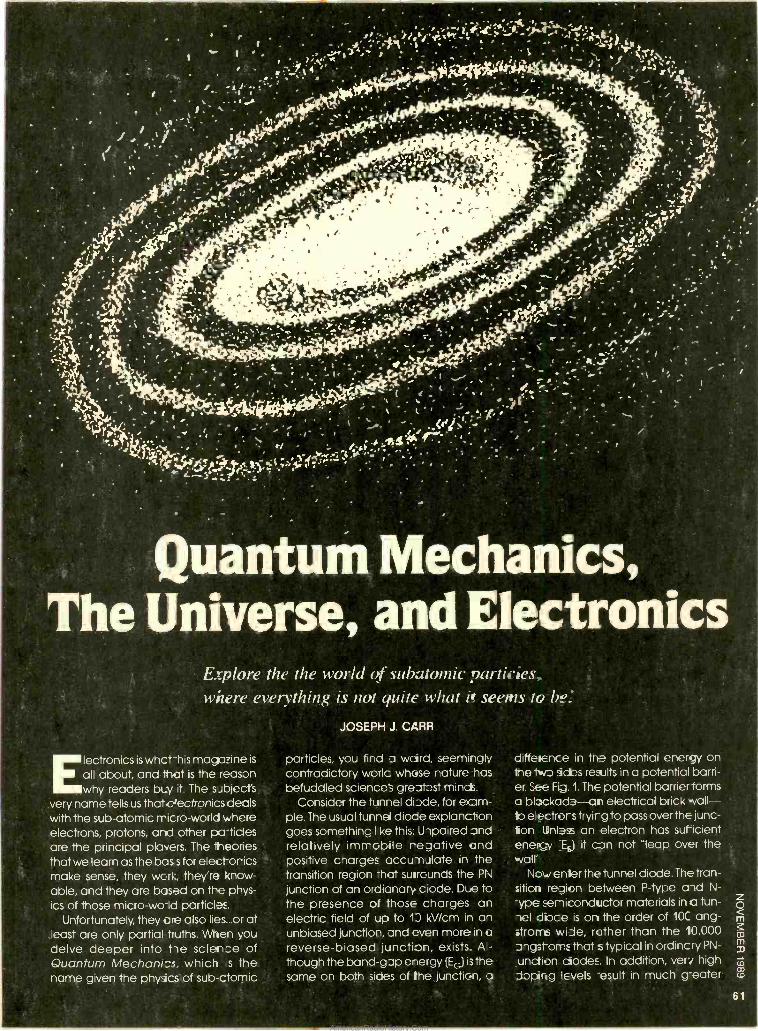
-
/./ I ,
' (,f,r ., -,;I(`. i : .
I
i +'y4'i'' r'>Y\w ` S r -`c~' +yr.Yf v .,..0 , '¡L/
N. 1( \ / } i`.. , . r : r, ,. ...lRi,±'t!rll}'-.T'. ,J. /-;
.I 1 1 ' . f' . /_!7/ _ t I ' . - l / \ . 1 _ ` , 1 . - , '1 t` r. r.\-'{,, . ..;;'; iÿ.
11,. 11,' j''. T1 ., ̀. . . , 1 -. , / - 't.. . - l- .f r! \ . ' .-
.
-r .4 /, %
. ;
.
.' , -1)11. .
ì ry`r .
:4).', ' .. , .
-
; , :L ,i.. .. .
.3
77 - _-
I , .
- I. 1..
.>;",,:. .,( .',_ 1- . .7> . : ' ' fI' `
. 'aY'Ec . ; - -\- , 'J J ' ì( Y '( ' ( ' \ J
1, J'Y' ,` `' - '
1 / . t ' f6y ̀ -4 . . ' . / rj_ f.;.r '1: .s%-"yY.
''.4 .0 ''. , .
. .
L' % . -'' ,
-' I . . ' , i 1, ,_
- ,` , .
pp . ÿ'~ ..- -. i -/` t>
- - 1 w_ÿ - ' ` -._
Quantum Mechanics, The Universe, and Electronics
Explore the the world of subatomic particles, where everything is not quite what if seems to be
JOSEPH J. CARR
Electronics iswhct -his magazine is
all about, and that is the reason why readers buy it. The sJbject's
very name tells us thate'ectronics deals with the sub -atomic micro -world where electrons, protons, and other particles are the principal players. The theories that we learn as the bas s for electorics make sense, they wcrl:, they're <now - able, and they are based on the phys- ics of those micro-wo-ld particles.
Unfortunately, they re also lies.. or at least are only partial truths. When you delve deeper into he science of Quantum Mechanics, which s the name given the physics of sub -ctomic
particles, you find a weird, seemingly cont-adictory wolc whose nature has
befuddled science's greatest minds. Consider the tunnel diode, for exam-
ple. The usual tunnel diode explanction goes something I ke this: U -)paired and relatively immobile regative and positive charges accu- nJlate in the transition region -hat suiraunds the PN
junction of an ordianary ciode. Due to the presence of those charges an electric field of up to 1D kV /cm in an unbiased junction, and even more in a
reverse -biased junction, exists. A -
though the band -gap energy (EG) is the same on both sides of the junction, a
diffeienee in the potential enemy on the two sides results in a potential barri- er. See Fig. 1. The potential barrier forms a blockade -an electrical brick wall - b e ectrors tryir g to pass over the junc- ion Unless an electron has sufricient enerc' :EE) it can not "leap over the wait
Now enter the tunnel diode. The tran- sition region between P -type aid N-
-ype semiconductor materials in a tun - el duce is on the order of 10C ang- stroms wile, rather than the 10,000 angst -oms that s typical in ordincry PN-
unction ciodes. In addition, veri high doping levels -esult in much g-eater
61
AmericanRadioHistory.Com
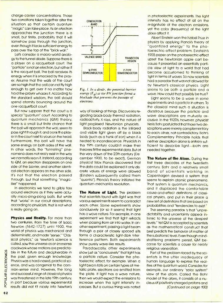
62
charge- carrier concentrations. Those two conditions taken together alter the situation so that certain quantum "magic" can take place. As an electron approaches the junction there is a small, but finite, probability that it will somehow pass through the junction, even though it lacks sufficient energy to pass over the top of the "brick wall."
Let's consider a macro -world analo- gy to the tunnel diode. Suppose there is
a player on a racquetball court. The "particle" is not an electron, but rather it is the racquet ball. The ball receives its
energy when it is smacked by the play- er. Assume that the walls of the court are so high that the ball can not fly high enough to get over it no matter how hard the player whacks it. According to the standard wisdom, the ball should spend eternity bouncing around the one racquetball court.
But now suppose that the court is a special "quantum" court. According to quantum mechanics (QM) theory, there is a small but finite chance that the ball will approach the wall, seem to pass right through it, and bonk the play- er in the court next to yours on the head. Furthermore, the ball will have the same energy on both sides of the wall. In other words, the "tunneling" phe- nomena does not really exist in the way we normally learn it. Instead, according to QM, an electron disappears on one side of the barrier, and another identi- cal electron appears on the other side. It's not that the electron passed through, but that something "magic - like" happened.
In electronics we tend to glibly toss around electrons as if they were actu- ally micro -ping -pong balls. But while that "works" in our circuit descriptions, according to physicists, that is not what is really going on.
Physics and Reality. For more than Iwo centuries, from the time of Isaac Newton (1642 -1727) until 1900, the world of physics was mechanical and deterministic, and made "sense." "Clas- sical physics," as Newton's science is
called, saw the universe as an immense clockwork whose motions are predicta- ble in the future and decipherable in the past, given enough knowledge. Physics was a hard -nosed, practical sci- ence, and was congenial to the com- mon -sense mind. However, the long and successful reign of classical physics was threatened in the late 19th century, in part because various experimental results did not fit nicely into Newton's
CONDUCTION BAND
VALENCE BAND TRANSITION REGION
N -TYPE SEMICONDUCTOR
P -TYPE SEMICONDUCTOR
Fig. I. In a diode, the potential- barrier energy (EB) at the PN junction forms a blockade that prevents the passage of electrons.
way of looking at things. Discoveries re- garding black -body thermal radiation, radioactivity, X -rays, and the nature of light perplexed Newtonian physicists.
Black -body radiation is the infrared and visible light given off by a black body (such as a hunk of iron) when it is
heated to incandescence. Physicists in the 19th century couldn't make their theories fitthe experimental data. But at the very dawn of the 20th century (De- cember 1900, to be exact), German physicist Max Planck discovered that the data could be explained if only dis- crete values of energy were allowed (Einstein subsequently called them "quanta'). Planck's theory initiated the quantum- mechanics revolution.
The Nature of Light. The problem that scientists found with light was that various experiments seem to contradict each other. Some experiments show conclusively (or so it seems) that light has a wave nature. For example, in one experiment we find that light refracts when passing from air into water. In an- other experiment, passing a light beam through a pair of closely spaced slits forms a characteristic light -dark inter- ference pattern. Both experiments show purely wave -like results.
Paradoxically, other experiments show just as "conclusively" that light has a particle nature. Consider the pho- toelectric effect, for example. When a light beam falls on certain types of me- tallic plate, electrons are emitted from the plate. If light has a wave nature, then we would expect the emissions to increase when the light intensity in- creases. But a curious thing was noted
in photoelectric experiments. The light intensity has no effect at all on the magnitude of the electron emissions, yet the color (frequency) of the light does affect it.
Albert Einstein won the Nobel Prize in physics by applying Planck's theory of "quantized energy" to the pho- toelectric- effect problem. Einstein's 1905 paper on the photoelectric effect upset the Newtonian apple cart be- cause it presented an essentially parti- cle view of light to a world that had become accustomed to thinking of light in terms of waves. So now scientists had a paradox that was not allowed for by Newton's classical physics. Light seems to be both a particle and a wave. How could that possibly be true?
Light seems to be a wave in some experiments and a particle in others. To
the classical mind such a situation is
disastrous because the particle and wave descriptions are mutually ex- clusive. In the 192O's, however, physicist Neils Bohr postulated that those two de- scriptions were merely complementary to each other, not contradictory. Bohr's Complementary Principle holds that neither description alone is entirely suf- ficient to describe light -both are needed together.
The Nature of the Atom. During the first three decades of the twentieth century, Bohr and a relatively small band of scientists working in Copenhagen devised a system that seems to explain atomic phenomena. That system is quantum mechanics, and it displaced the comfortable cause -and -effect definitions of classi- cal physics, and put in their place a new set of definitions that are based on probabilities and "tendencies to exist."
The seeming paradox is that "unpre- dictability and uncertainty appear in- trinsic to the universe at the deepest levels." Yet QM is accepted by scientists as the mathematical construct that best predicts the behavior of matter at the subatomic level. Even though mind - shattering problems persist, QM be- came for scientists a cause for nearly religious veneration.
Part of the problem faced by the sci- entists is the utter inadequacy of human language to express the real- ities of the quantum world. Consider, for example, our ordinary "solar system" view of the atom. Called the Bohr model of the atom, it consists of a nu- cleus of positively charged protons and
(Continued on page 100)
AmericanRadioHistory.Com
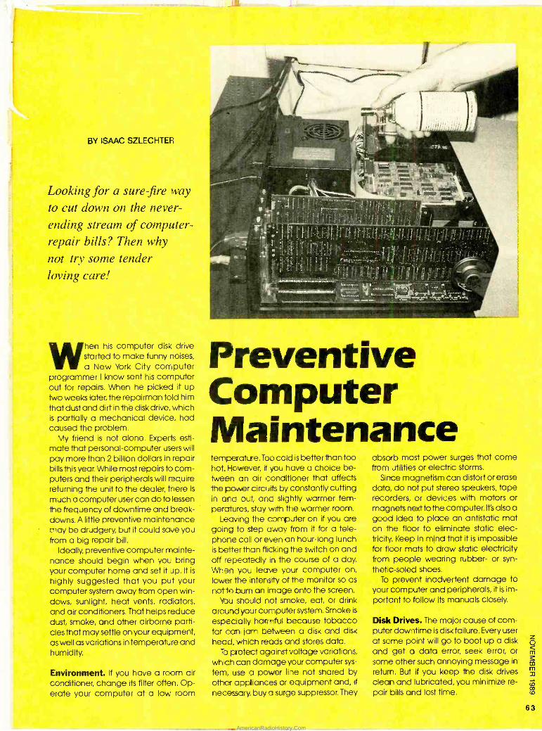
BY ISAAC SZLECHTER
Looking for a sure-fire way
to cut down on the never - ending stream of computer - repair bills? Then why
not try some tender loving care!
When his computer disk drive started to make funny noises,
a New York City computer programmer I know sent his computer out for repairs. When he picked it up Iwo weeks later, the repairman told him that dust and dirt in the disk drive, which is partially a mechanical device, had caused the problem.
My friend is not alone. Experts esti- mate that personal- computer users will pay more than 2 billion dollars in repair bills this year. While most repairs to corn - puters and their peripherals will require returning the unit to the dealer, here is
much a computer user can do to lessen the frequency of downtime and break- downs. A little preventive maintehance may be drudgery, but it could save you from a big repair bill.
Ideally, preventive computer mainte- nance should begin when yogi bring your computer home and set it Jp. It is
highly suggested that you put your computer system away from open win- dows, sunlight, heat vents, radiators, and air conditioners. That helps reduce dust, smoke, and other airborne parti- cles that may settle on your equipment, as well as variations in temperatLre and humidity.
Environment. If you have a room air conditioner, change its filter often. Op- erate your computer at a low room
Preventive Computer Maintenance temperature. Too cold is better than too hot. However, if you have a choice be- tween an air conditioner that affects the power clircuirs by constantly cutting in and out, and slightly warmer tem- peratures, stay with the warmer room.
Leaving the computer on if you are going to step away from it for a tele- phone calk or even an hour -long lunch is better than flicking the switch on and off repeatedly in the course of a day. When yoL leave your computer on, lower 'he intensity of the monitor so as
not to burn an image onto the screen. You should not smoke, eat, or drink
around your computer system. Smoke is
especially harmful because tobacco tar can jam between a disk and disk
head, which reads and stores data. lb protect against voltage variations,
which can damage your computer sys-
tem, use a power line not shared by other appliances or equipment and, if
necessary buy a su'ge suppressor. They
absorb most power surges that come from utilities or electric storms.
Since magnetism can distort or erase data. do not put stereo speakers, tape recorders, or devices with motors or magnets next to the computer. It's also a good idea to place an antistatic mat on the floor to eliminate static elec- tricity. Keep in mind that it is impossible for floor mats to draw static electricity from people wearing rubber- or syn-
thetic-soled shoes. To prevent inadvertent damage to
your computer and peripherals, it is im- portant to follow its manuals closely.
Disk Drives. The major cause of com- puter downtime is disk failure. Every user at some point will go to boot up a disk and get a data error, seek error, or some other such annoying message in
return. But if you keep the disk drives clean and lubricated, you minimize re- pair bills and lost time.
63
AmericanRadioHistory.Com
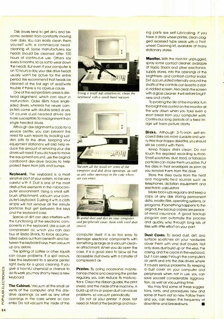
64
Disk drives tend to get dirty and be- come oxidized from constantly moving over disks. You can easily clean them yourself with a commercial head - cleaning kit. Some manufacturers say heads should be cleaned after 100 hours of continuous use. Others say every 6 months, so as not to wear down the heads. But even if your computer is
on 10 hours a day, your disk drive heads usually won't be active for the entire period. We recommend that heads be cleaned at the first sign of read /write trouble if there is no obvious cause.
One of the real problem areas is disk - head alignment, which can result in malfunction. Older IBM's have single - sided drives, whereas the newer com- puters come with double -sided drives. Of course dual- headed drives are more susceptible to misalignment than single- headed drives.
Although disk alignment is a job for a service center, you can prevent the need for such repairs by avoiding sud- den jolts to the drive. Keeping your equipment stationary will also help re- duce the amount of servicing your disk drives will need. If you do have to move the equipment around, use the original cardboard disk -drive braces to help protect them from jolts and bumps.
Keyboard. The keyboard is a most sensitive part of your system, so be very careful with it. Dust is one of the most destructive elements in the microcom- puter environment. Using a small soft- brush attachment, vacuum your com- puter's keyboard. Dusting it with a cloth simply will not remove all the minute particles that get between the keys and the keyboard case.
Specks of dirt can also interfere with the functioning of the electronic com- ponents in the keyboard. Use a can of compressed air, which you can also buy at Radio Shack, to force accumu- lated debris out from beneath and be- tween the keyboard keys, then vacuum up any debris.
The spilling of coffee or other liquids can cause problems. If a spill occurs, take the keyboard to a service center right away for a good cleaning. If you give a harmful chemical a chance to do its work, you may shortly need a new keyboard.
The Cabinet. Vacuum all the small air vents of the computer and the disk - drive openings, as well as any other openings in the case where air can enter. Do not vacuum the inside of the
Using a small soft attachment, clean the keyboard with a small hand vacuum.
Vacuum all the small air vents of the computer and disk drive openings, as well as any other openings in the case where air can enter.
To avoid dust and dirt on your computer and peripherals cover them with vinyl dust covers.
computer itself. It is all too easy to damage electronic components with something as large as a vacuum clean- er attachment. When you do open the case, it is a good idea to blow all the accessible dust away with a canister of compressed air.
Printer. By doing occasional mainte- nance checks and cleaning the printer regularly, you can reduce its malfunc- tions. Clean the ribbon guides, the print shield, and the inside of the machine. A build -up of ink or paper dust can cause problems, so vacuum periodically.
Do not oil your printer. It does not need oil. Most of the bearings and mov-
ing parts are self - have a daisy wheel ged recessed type wheel Cleaning kit, stationary stores.
lubricating. If you printer, clean clog - areas with a Print - available at many
Monitor. With the monitor unplugged, spray some contact cleaner, available at Radio Shack and other electronics - supply stores, into the openings of the brightness- and contrast- control knobs. Dirt accumulated internally around the shafts of the controls can lead to a stat- ic- riddled screen. Also clean the screen with a glass cleaner. It will restore bright- ness and clarity.
To prolong the life of the monitor, turn the brightness control on the monitor all the way down when you take even a short break from your computer work. Continuous long periods of a fixed im- age will harm picture clarity.
Disks. Although 3 -1 -inch self -en- cased disks are more durable and wor- ry -free than floppy diskettes, you should still be careful with them.
Keep floppy disks clean. Do not touch the exposed recording surface. Small scratches, dust, food, or tobacco particles can make them unusable. Put the disks in their envelopes as soon as you remove them from the drive.
Store the disks away from the heat and magnetic -field sources such as telephones, dictation equipment, and electronic calculators.
Make back -ups regularly and keep a copy of any disk storing permanent data, master files, operating systems, or programs. If something happens to the original, the backup copies are peace - of -mind insurance. A good backup program can automate the process and quickly whiz through long lists of files with little effort on your part.
Dust Cover. To avoid dust, dirt, and surface scratches on your hardware cover them with vinyl dust covers. Not only does dust build up on the keys, the casing, and the cracks in the keyboard, but it can seep through the computer's air vents and into the disk drives, where it causes serious problems. By keeping a dust cover on your computer and peripherals when not in use, you can save yourself considerable aggrava- tion, as well as vacuuming time.
You may find some of these sugges- tions, hints, and procedures new and some of them not so new. Follow them and you can lessen the frequency of downtime and breakdowns.
AmericanRadioHistory.Com
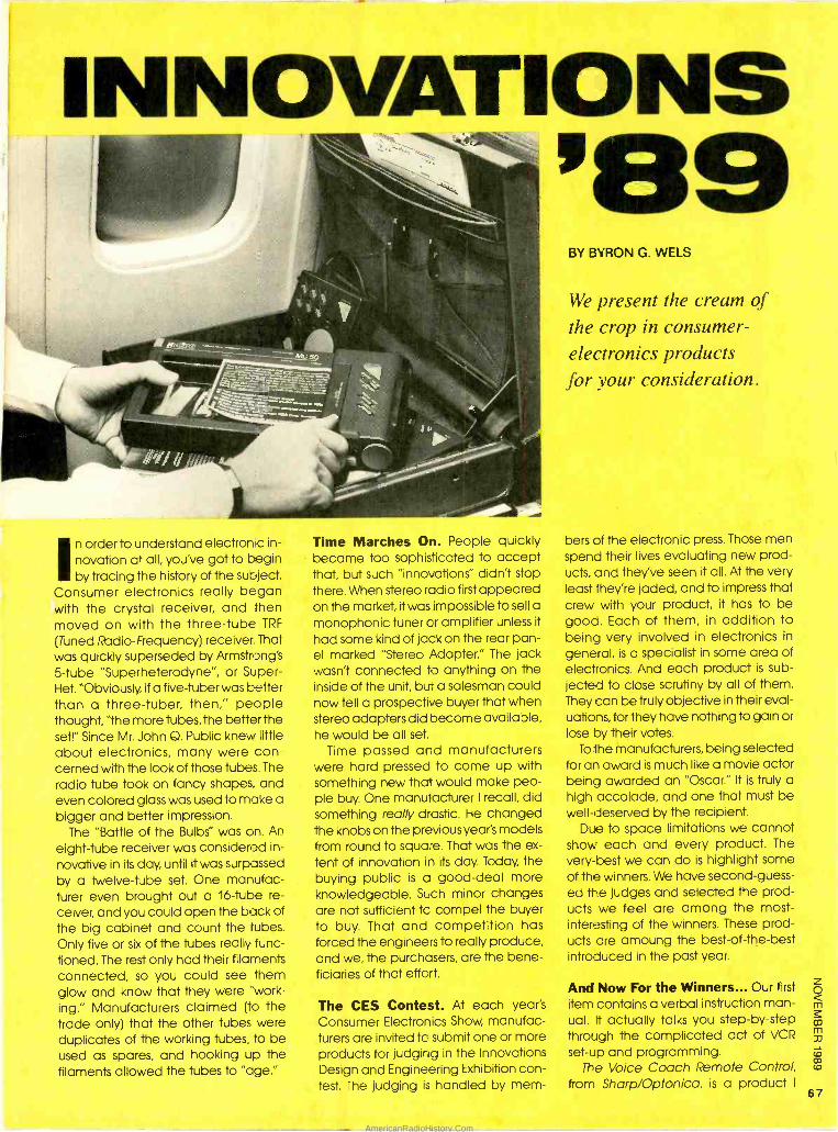
INNOVATIONS X89
In order to understand electronic in-
novation at all, you've got to begin by tracing the history of the subject.
Consumer electronics really began with the crystal receiver, and then moved on with the three -tube TRF
(Tuned Radio- Frequency) receiver That was quickly superseded by Armstrong's 5 -tube "Superheterodyne ", or Super - Het. "Obviously, if a five -tuber was better than a three -tuber, then," people thought, "the more tubes, the better the set!" Since Mr. John Q. Public knew little about electronics, many were con- cerned with the look of those tubes. The
radio tube took on fancy shapes, and even colored glass was used to make a bigger and better impression.
The "Battle of the Bulbs" was on. An
eight -tube receiver was considered in-
novative in its day, until it was surpassed by a twelve -tube set. One manufac- turer even brought out a 16 -tube re-
ceiver, and you could open the back of the big cabinet and count the tubes.
Only five or six of the tubes really func- tioned. The rest only had their filaments connected, so you could see them glow and know that they were "work- ing." Manufacturers claimed (to the trade only) that the other tubes were duplicates of the working tubes, to be used as spares, and hooking up the filaments allowed the tubes to "age."
Time Marches On People quickly became too sophisticated to accept that, but such "innovations" didn't stop there. When stereo radio first appeared on the market, it was impossible to sell a
monophonic tuner or amplifier unless it
had some kind of jack on the rear pan- el marked "Stereo Adapter." The jack wasn't connected to anything on the inside of the unit, but a salesman could now tell a prospective buyer that when stereo adapters did become available, he would be all set.
Time passed and manufacturers were hard -pressed to come up with something new that would make peo- ple buy. One manufacturer I recall, did something really drastic. He changed the knobs on the previous year's models from round to square. That was the ex-
tent of innovation in its day. Today, the buying public is a good -deal more knowledgeable. Such minor changes are not sufficient tc compel the buyer to buy. That and competition has forced the engineers to really produce, and we, the purchasers, are the bene- ficiaries of that effort.
The CES Contest. At each year's Consumer Electronics Show, manufac- turers are invited tc submit one or more products for judging in the Innovations Design and Engineering Exhibition con- test. The judging is handled by mem-
BY BYRON G. WELS
We present the cream of the crop in consumer - electronics products for your consideration.
bers of the electronic press. Those men spend their lives evaluating new prod- ucts, and they've seen it all. At the very least they're jaded, and to impress that crew with your product, it has to be gooa. Each of them, in addition to being very involved in electronics in
general, is a specialist in some area of electronics. And each product is sub-
jected to close scrutiny by all of them. They can be truly objective in their eval- uations, for they have nothing to gain or lose by their votes.
To the manufacturers, being selected for an award is much like a movie actor being awarded an "Oscar." It is truly a high accolade, and one that must be well -deserved by the recipient.
Due to space limitations we cannot show each and every product. The
very -best we can do is highlight some of the winners. We have second- guess-
ed the judges and selected the prod- ucts we feel are among the most - interesting of the winners. These prod- ucts are amoung the best -of- the -best introduced in the past year.
And Now For the Winners... Our first
item contains a verbal instruction man- ual. It actually talks you step -by -step through the complicated act of VCR
set -up and programming. The Voice Coach Remote Control,
from Sharp /Optonica, is a product I
67
AmericanRadioHistory.Com
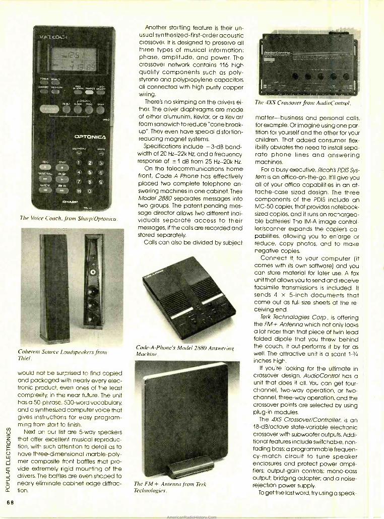
VUi=_'E 0.k. +
o
O?TONICA
Alk;
FAUSE'SPLI
ti7W
ST!OF
'Pt AY
!FF-
v 1
4
7
2
5
ß
68
The Voice Coach. from SharplOptonica.
Coherent Source Loudspeakers from Thiel.
would not be surprised to find copied and packaged with nearly every elec- tronic product, even ones of the least complexity, in the near future. The unit has a 50- phrase, 500 -word vocabulary, and a synthesized computer voice that gives instructions for easy program- ming from start to finish.
Next on our list are 5 -way speakers that offer excellent musical reproduc- tion, with such attention to detail as to have three -dimensional marble -poly- mer composite front baffles that pro- vide extremely rigid mounting of the drivers. The baffles are even shaped to nearly eliminate cabinet -edge diffrac- tion.
Another startling feature is their un- usual synthesized- first -order acoustic crossover. It is designed to preserve all three types of musical information: phase, amplitude, and power. The crossover network contains 116 high quality components such as poly- styrene and polypropylene capacitors all connected with high purity copper wiring.
There's no skimping on the drivers ei- ther. The driver diaphragms are made of either alumunim, Kevlar, or a Kevlar/ foam sandwich to reduce "cone break- up". They even have special distortion - reducing magnet systems.
Specifications include - 3-dB band- width of 20 Hz -22k Hz, and a frequency response of ± 1 dB from 25 Hz -20k Hz.
On the telecommunications home front, Code -A -Phone has effectively placed Iwo complete telephone an- swering machines in one cabinet. Their Model 2880 separates messages into two groups. The patent -pending mes- sage director allows two different indi- viduals separate access to their messages, if the calls are recorded and stored separately.
Calls can also be divided by subject
Code-A-Phone's Model 2880 Answering Machine.
The FM + Antenna from Terk Technologies.
The 4XS Crossover from AudioControl.
matter -business and personal calls, for example. Or imagine using one par- tition for yourself and the other for your children. That added consumer flex- ibility obviates the need to install sepa- rate phone lines and answering machines.
For a busy executive, Ricoh's PD /S Sys- tem is an office -on- the -go. MI give you all of your office capabilities in an at- tache -case sized design. The three components of the PDIS include an MC -50 copier, that provides notebook - sized copies, and it runs on rechargea- ble batteries! The IM -A image control- ler /scanner expands the copier's ca- pabilities, allowing you to enlarge or reduce, copy photos, and to make negative copies.
Connect it, to your computer (it comes with its own software) and you can store material for later use. A fax unit that allows you to send and receive facsimile transmissions is included. It sends 4 x 5 -inch documents that come out as full -size sheets at the re- ceiving end.
Terk Technologies Corp., is offering the FM+ Antenna which not only looks a lot nicer than that piece of twin -lead folded dipole that you threw behind the couch, it out -performs it by far as well. The attractive unit is a scant 1 -3/4
inches high. If you're looking for the ultimate in
crossover design, AudioControl has a unit that does it all. You can get four - channel, two -way operation, or two - channel, three -way operation, and the crossover points are selected by using plug -in modules.
The 4XS Crossover /Controller, is an 18 -dB /octave state -variable electronic crossover with subwoofer outputs. Addi- tional features include switchable, non - fading bass; a programmable frequen- cy -match circuit to tune speaker enclosures and protect power ampli- fiers; output -gain controls; mono -bass output; bridging adapter; and a noise - rejection power supply.
To get the last word, try using a speak-
AmericanRadioHistory.Com
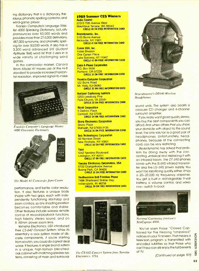
ing dictionary that is a dictionary, the- saurus, phonetic spelling corrector, and word -game player.
Franklin Computer's Language Mas-
ter 4000 Speaking Dictionary, actually pronounces over 83,000 words and provides more than 274,000 definitions, 487,000 synonyms, and phonetic spell-
ing for over 83,000 words. It also has a
3,300 -word advanced SAT (Sudent Aptitude Test) word list that it uses in a
wide variety of challenging word games.
In the camcorder market, Canon's 8mm Model Al makes use of the Hi -8
standard to provide increased horizon-
tal resolution, improved signal -to -noise
Franklin Computer' Language AIa.stzr
4000 Electronic Dictionary.
The Model Al Camcorder from Canon.
performance, and better color resolu-
tion. It also features a unique body shape with two grips, each with inde- pendently functioning start /stop and zoom controls, so any shooting position becomes comfortable and stable. Other features include wireless remote control of record /playback functions, high -fidelity stereo sound, and an 8-80mm power -zoom lens.
Yamaha Electronics, USA introduced their CS -642 Concert System. While it's
essentially a rack system made of dis-
crete components, if you're starting from scratch, you could do a great deal worse. It features a single -brand system
in a unique, high- fashion bleached - oak cabinet with matching speaker sys-
tems, consisting of main and surround-
1989 Summer CES Winners Audio Control 22313 70th Avenue West Mountlake Terrace, WA 98043
CIRCLE 40 ON FREE INFORMATION CARD
Beyerdynamic, Inc.
5 -05 Burns Avenue Hicksville, NY 11801
CIRCLE 41 ON FREE INFORMATION CARD
Canon USA, Inc. Video Division One Canon Plaza Lake Success, NY 11042
CIRCLE 42 ON FREE INFORMATION CARD
Code -A -Phone Corporation P.O. Box 5656 Portland, OR 97228
CIRCLE 31 ON FREE NFORMATION CARD
Franklin Computer Corporation 122 Burrs Road Mt. Holly, NJ 08060
CIRCLE 32 ON FREE INFORMATION CARD
National Captioning Institute 5203 Leesburg Pike Falls Church, VA 22041
CIRCLE 33 ON FREE INFORMATION CARD
Ricoh Corporation 5 Dedrick Place Caldwell, NJ 07006
CIRCLE 34 ON FREE INFORMATION CARD
Sharp Electronics Corporation Sharp Plaza Mahwah, NJ 07430 -2135
CIRCLE 35 ON FREE INFORMATION CARD
Terk Technologies Corporation 56 Harrison Street New Rochelle, NY 1C801
CIRCLE 36 ON FREE INFORMATION CARD
Thiel 1042 Nandino Boulevard Lexington, KY 40511
CIRCLE 37 ON FREE INFORMATION CARD
Yamaha Electronics Corporation, USA
6722 Orangethorpe Avenue Buena Park, CA 90620
CIRCLE 38 ON FREE INFORMATION CARD
Southwestern Bell Freedom Phone
7486 Shadeland Station Way Indianapolis, IN 46256
CIRCLE 39 ON FREE INFORMATION CARD
The CS -642 Concert System from Yamaha
Electronics, USA.
Beyerdynamic's DT690 Wireless
Headphones.
sound units. The system also boasts a carousel CD changer and 4- channel surround amplifier.
If you really want good quality stereo,
you buy the best components you can afford. And when others that you share
your domicile with object to the sound level, the only solution is a good pair of headphones. Unfortunately, head- phones, because of the connecting cord, can be very restricting.
Beyerdynamic has solved that prob- lem by doing away with the con- necting umbilical and replacing it with an infrared beam. The DT 690 phones come with the IS 690 infrared transmit- ter and the LG 690 power supply. You
won't be sacrificing quality, either: it has
a 20- 20,000 Hz frequency response. You get a built -in rechargeable 9 -volt battery, a volume control, and MONO/
STEREO switch to boot.
National Captioning Institute's TeleCaption 4000.
You've seen those "Closed Cap- tioned for the Hearing Inmpaired" notices on your 1V screen. That means a
television program is transmitted with
encoded subtitles so that those who can't hear can still enjoy the full benefits of iV
(Continued on page 101)
69
AmericanRadioHistory.Com
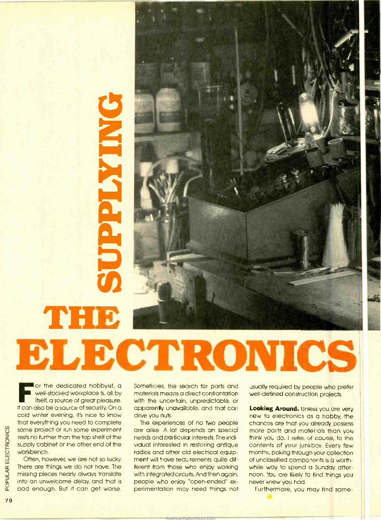
70
ELECTRONICS or the dedicated hobbyist, a well- stocked workplace is, all by itself, a source of great pleasure.
It can also be a source of security. On a cold winter evening, it's nice to know that everything you need to complete some project or run some experiment rests no further than the top shelf of the supply cabinet or the other end of the workbench.
Often, however, we are not so lucky.
There are things we do not have. The missing pieces nearly always translate into an unwelcome delay, and that is
bad enough. But it can get worse.
Sometimes, the search for parts and materials means a direct confrontation with the uncertain, unpredictable, or apparenly unavailable, and that can drive you nuts.
The experiences of no two people are alike. A lot depends on special needs and particular interests. The indi- vidual interested in restoring antique radios and other old electrical equip- ment will have requirements quite dif- ferent from those who enjoy working with integrated circuits. And then again, people who enjoy "open- ended" ex- perimentation may need things not
usually required by people who prefer well- defined construction projects.
Looking Around. Unless you are very new to electronics as a hobby, the chances are that you already possess more parts and materials than you think you do. I refer, of course, to the contents of your junkbox. Every few months, poking through your collection of unclassified components is a worth- while way lo spend a Sunday after- noon. You are likely to find things you never knew you had.
Furthermore, you may find some-
AmericanRadioHistory.Com
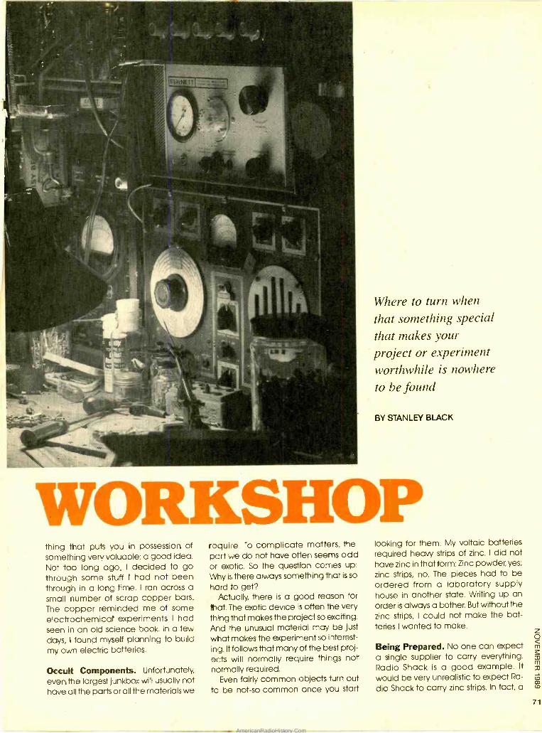
Where to turn when
that something special that makes your project or experiment worthwhile is nowhere
to be ,found
BY STANLEY BLACK
WORKSHOP thing that puts you in possession of something very valuable: a good idea. Not too long ago, I decided to go through some stuff I had not been through in a long time. I ran across a small number of scrap copper bars.
The copper reminded me of some electrochemical experiments I had seen in an old science book. In a few days, 1 found myself planning to build my own electric batteries.
Occult Components. Unfortunately, even the largest junkbox will usually not have all the parts or all the materials we
require. To complicate matters, the part we do not have often seems odd or exotic. So the question comes up:
Why is there always something that is so
hard to get? Actually, there is a good reason for
that. The exotic device is often the very thing that makes the project so exciting. And the unusual material may be just what makes the experiment so interest-
ing. It follows that many of the best proj- ects will normally require things not normally required.
Even fairly common objects turn out to be not -so- common once you start
looking for them. My voltaic batteries required heavy strips of zinc. I did not have zinc in that form: Zinc powder, yes;
zinc strips, no. The pieces had to be ordered from a laboratory supply house in another state. Writing up an order is always a bother. But without the zinc strips, I could not make the bat- teries I wanted to make.
Being Prepared. No one can expect a single supplier to carry everything. Radio Shack is a good example. It
would be very unrealistic to expect Ra-
dio Shack to carry zinc strips. In fact, a
71
AmericanRadioHistory.Com
72
NAMES AND ADDRESSES All- Electronics Corporation P.O. Box 567 Van Nuys, CA 91408.
CIRCLE 27 ON FREE INFORMATION CARD
Antique Electronic Supply 688 W. First St. Tempe, AZ 85281
CIRCLE 28 ON FREE INFORMATION CARD
B & L Scientific P0. Box 1054 Duvall, WA 98019 -1054
CIRCLE 29 ON FREE INFORMATION CARD
Chem -Lab 13814 Inglewood Ave. Hawthrone, CA 90250
CIRCLE 30 ON FREE INFORMATION CARD
Consolidated Electronics Incorporated 705 Watervliet Ave. Dayton, OH 45420 -2599
CIRCLE 75 ON FREE INFORMATION CARD
Dick Smith Electronics USA P.O. Box 468 Greenwood, IN 46142
CIRCLE 76 ON FREE INFORMATION CARD
Electronic Liquidators PO. Box 27656 Lansing, MI 48901
CIRCLE 77 ON FREE INFORMATION CARD
Fair Radio Sales 1016 E. Eureka Lima, OH 45802
CIRCLE 78 ON FREE INFORMATION CARD
Jerry Co Inc. 601 Linden PI.
Evanston, IL 60202 CIRCLE 79 ON FREE INFORMATION CARD
Hagenow Laboratories 1302 Washington St. Manitowoc, WI 54220
CIRCLE 80 ON FREE INFORMATION CARD
Halted Specialties 3500 Ryder St. Santa Clara, CA 95951
CIRCLE 21 ON FREE INFORMATION CARD
Lindsay Publications PO. Box 12 -WF5 Bradley, IL 60915
CIRCLE 22 ON FREE INFORMATION CARD
Mark V Electronics 8019 E. Slauson Ave. Montebello, CA 90640
CIRCLE 23 ON FREE INFORMATION CARD
Newark Electronics 4801 Ravenswood Ave. Chicago, IL, 60640
CIRCLE 24 ON FREE INFORMATION CARD
Peary Communications 12922 Harbor Blvd., Suite 800 Garden Grove, CA 92640
CIRCLE 26 ON FREE INFORMATION CARD
trip to the local hardware store ended with the discovery that it is unrealistic to expect some people to know what a zinc strip is!
So, for many of us, getting parts usu- ally means getting them from a mail - order company. This does not have to
be a frustrating, disappointing, or time - consuming activity. It all, I suppose, comes down to preparation. It is good to know beforehand where you are likely to find the parts or materials you are looking for. That means being famil- iar with what at least a few of the corn - ponies have to offer. Such is the purpose of this article.
The first step is to become familiar with the large number of companies out there and what they carry. And a good place to start is the relatively comprehensive list that appeared in the article "The Parts Connection" by Jack Cunkleman (Popular Electronics, July 1989). If what you need is a cur- rently manufactured part from all but the most obscure company, the odds are pretty good that one or more of them can come through.
We are not going to duplicate Jack's work here. Instead, we are going to look at where to turn to when our needs are more esoteric. Who carries surplus components? Who stocks fun gear for the electronics experimenter? Where can you get odd materials or chemi- cals? And so forth.
An Excellent Selection. One of the electronic supply, mail -order compa- nies I regularly turn to is the All -Elec- tronics Corporation. The All- Electronics inventory features a superior selection of parts and components. This includes a wide variety of semiconductors (tran- sistors, diodes etc), resistors, capacitors, switches, connectors, fasteners, project cases, batteries, and power supplies. Most components are available in the small quantities generally required by hobbyists. In addition, however, every free quarterly catalog introduces new items of special interest to experimen- ters, like a polarity switch, strobe unit, giant pushbutton, musical telephone ringer, or light- activated motion sensor and many others.
In addition, the All- Electronics cata- log is actually fun to look through, and I
recommend saving them. The mini- mum order from the company is $10.00 and there is a $3.00 charge for shipping and handling within the USA.
Another company that offers a sim- ilar merchandise line up is Halted Spe- cialties. Along with a good selection of components, they sell lasers, optical gear, and surplus equipment for experi- menters. Their catalog costs $1.00 by mail, but is available free of charge with orders or if you stop in at any of their three California stores.
Kits and Plans. For those of you who enjoy working with a variety of kits and plans, however, it may be necessary to widen your search. One place to look is
called Electronic Liquidators. A recent catalog from this company featured a number of very interesting kits, most of which are available for less than $15.00; some are less than $5.00. Included in the selection are a transistor tester, ca- pacitor tester, resistance box, function generator, LED level meter, microwave - oven leak detector, wireless micro- phone, electronic roulette circuit, and other items. An Electronic Liquidators catalog is $3.50.
Dick Smith is alive and well, and is
now living in Indiana. Dick Smith Elec- tronics USA offers a potpourri of interest- ing gear and components from down under, along with many of the popular Dick Smith kits. Catalogs are available for $2.00.
Audio enthusiasts will want to be- come familiar with the offerings of Mark V Electronics. They are the sole U.S.
agents for Sound Master (H.K.) Elec- tronics and Tung Yung Electrical Com- pany, two of the most popular kit makers in Asia and Europe. The projects available range from test instruments to talking clocks, but their line -up of audio equipment is especially impressive. The kits are rated according to ease- of -as- sembly, and are reasonably priced. The Mark V catalog is available free of charge.
High -voltage construction projects have been popular with amateur ex- perimenters for a long time. A west - coast company called B & L Scientific seems to specialize in things of that sort. From B & L Scientific you can get infor- mation on how to build elec- trophotographic equipment, lightning bulbs, Tesla coils, as well as some other very strange devices that date clear back to the late 19th century. The B & L
catalog, which is well -written and high- ly informative, is free of charge.
Another good source for plans for electronics projects and experiments is
Lindsay Publications. Their library con- sists of books on antique receivers, spark -gap transmitters, Tesla coils, Wimshurst lightning -bolt generators, lasers, and even the so- called "fringe sciences." The Lindsay's Electrical Books catalog costs $1.00.
Miscellaneous Materials. And speaking of a good catalog, not to mention a great collection of unusual
(Continued on page 98)
AmericanRadioHistory.Com
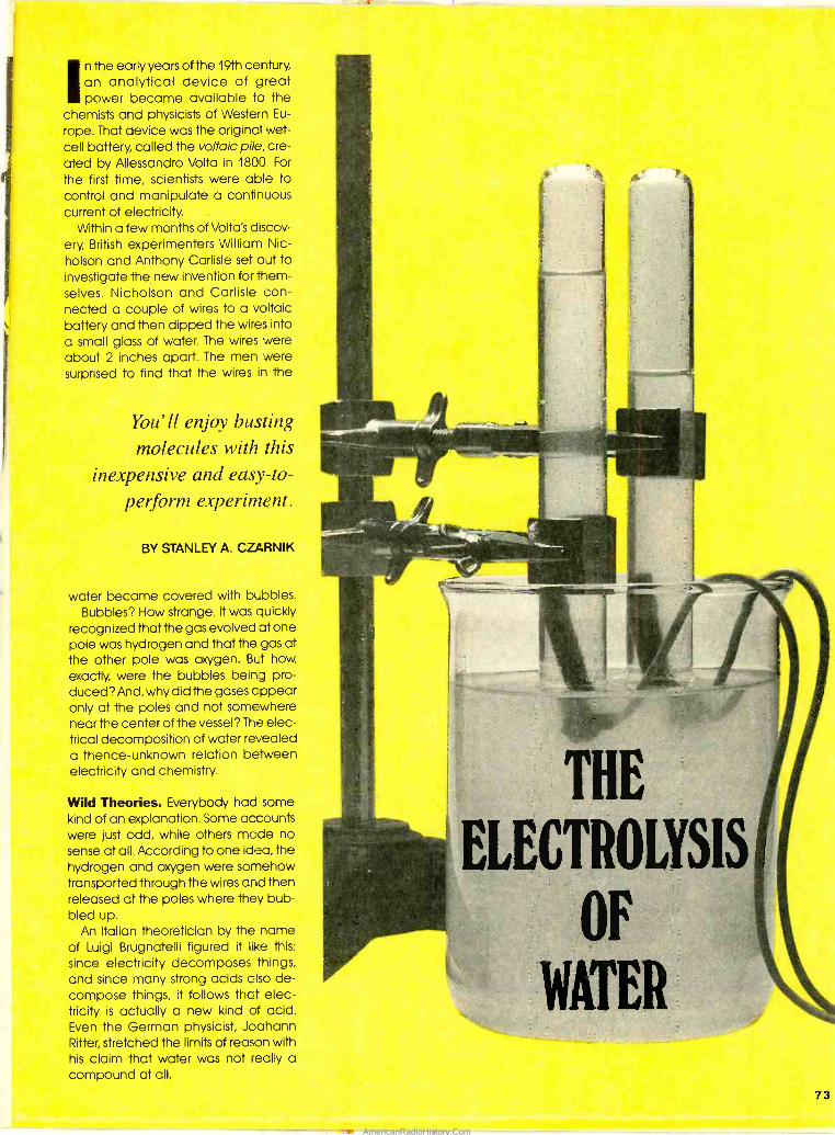
In the early years of the 19th century, an analytical device of great power became available to the
chemists and physicists of Western Eu-
rope. That device was the original wet - cell battery, called the voltaic pile, cre- ated by Allessandro Volta in 1800. For
the first time, scientists were able to control and manipulate a continuous current of electricity.
Within a few months of Volta's discov- ery, British experimenters William Nic- holson and Anthony Carlisle set oJt to investigate the new invention for them- selves. Nicholson and Carlisle con- nected a couple of wires to a voltaic battery and then dipped the wires into a small glass of water. The wires were about 2 inches apart. The men were surprised to find that the wires in the
You'll enjoy busting molecules with this
inexpensive and easy -to-
perform experiment.
BY STANLEY A. CZARNIK
water became covered with bubbles. Bubbles? How strange. It was quickly
recognized that the gas evolved at one pole was hydrogen and that the gas at the other pole was oxygen. But how exactly, were the bubbles being pro- duced? And, why did the gases appear only at the poles and not somewhere near the center of the vessel? The elec- trical decomposition of water revealed a thence -unknown relation between electricity and chemistry.
Wild Theories. Everybody had some kind of an explanation. Some accounts were just odd, while others made no sense at all. According to one idea, the hydrogen and oxygen were somehow transported through the wires arid then released at the poles where they bub- bled up.
An Italian theoretician by the name of Luigi Brugnatelli figured it like this:
since electricity decomposes things, and since many strong acids also de- compose things, it follows that elec- tricity is actually a new kind of acid. Even the German physicist, Joahann Ritter, stretched the limits of reason with his claim that water was not really a compound at all.
4.
73
AmericanRadioHistory.Com
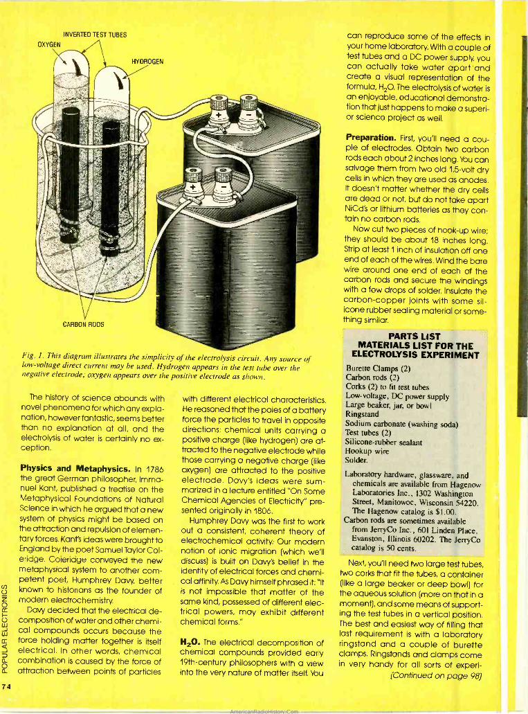
74
INVERTED TEST TUBES
O O i
-¡-35 '°-. 4® \ \\\
Fig. I. This diagram illustrates the simplicity of the electrolysis circuit. Any source of low - voltage direct current may be used. Hydrogen appears in the test tube over the negative electrode; oxygen appears over the positive electrode as shown.
The history of science abounds with novel phenomena for which any expla- nation, however fantastic, seems better than no explanation at all, and the electrolysis of water is certainly no ex- ception.
Physics and Metaphysics. In 1786 the great German philosopher, Imma- nuel Kant, published a treatise on the Metaphysical Foundations of Natural Science in which he argued that a new system of physics might be based on the attraction and repulsion of elemen- tary forces. Kant's ideas were brought to England by the poet Samuel Taylor Col- eridge. Coleridge conveyed the new metaphysical system to another com- petent poet, Humphrey Davy, better known to historians as the founder of modern electrochemistry.
Davy decided that the electrical de- composition of water and other chemi- cal compounds occurs because the force holding matter together is itself electrical. In other words, chemical combination is caused by the force of attraction between points of particles
with different electrical characteristics. He reasoned that the poles of a battery force the particles to travel in opposite directions: chemical units carrying a positive charge (like hydrogen) are at- tracted to the negative electrode while those carrying a negative charge (like oxygen) are attracted to the positive electrode. Davy's ideas were sum- marized in a lecture entitled "On Some Chemical Agencies of Electricity" pre- sented originally in 1806.
Humphrey Davy was the first to work out a consistent, coherent theory of electrochemical activity. Our modern notion of ionic migration (which we'll discuss) is built on Davy's belief in the identity of electrical forces and chemi- cal affinity. As Davy himself phrased it: "It is not impossible that matter of the same kind, possessed of different elec- trical powers, may exhibit different chemical forms."
H2O. The electrical decomposition of chemical compounds provided early 19th- century philosophers with a view into the very nature of matter itself. You
can reproduce some of the effects in your home laboratory. With a couple of test tubes and a DC power supply, you can actually take water apart and create a visual representation of the formula, H2O. The electrolysis of water is
an enjoyable, educational demonstra- tion that just happens to make a superi- or science project as well.
Preparation. First, you'll need a cou- ple of electrodes. Obtain two carbon rods each about 2 inches long. You can salvage them from two old 1.5 -volt dry cells in which they are used as anodes. It doesn't matter whether the dry cells are dead or not, but do not take apart NiCd's or lithium batteries as they con- tain no carbon rods.
Now cut two pieces of hook -up wire; they should be about 18 inches long. Strip at least 1 inch of insulation off one end of each of the wires. Wind the bare wire around one end of each of the carbon rods and secure the windings with a few drops of solder. Insulate the carbon -copper joints with some sil- icone rubber sealing material or some- thing similar.
PARTS LIST MATERIALS LIST FOR THE
ELECTROLYSIS EXPERIMENT
Burette Clamps (2) Carbon rods (2) Corks (2) to fit test tubes Low-voltage, DC power supply Large beaker, jar, or bowl Ringstand Sodium carbonate (washing soda) Test tubes (2) Silicone- rubber sealant Hookup wire Solder.
Laboratory hardware, glassware, and chemicals are available from Hagenow Laboratories Inc., 1302 Washington Street, Manitowoc, Wisconsin 54220. The Hagenow catalog is $1.00.
Carbon rods are sometimes available from JerryCo Inc., 601 Linden Place, Evanston, Illinois 60202. The JerryCo catalog is 50 cents.
Next, you'll need two large test tubes, Iwo corks that fit the tubes, a container (like a large beaker or deep bowl) for the aqueous solution (more on that in a moment), and some means of support- ing the test tubes in a vertical position. The best and easiest way of filling that last requirement is with a laboratory ringstand and a couple of burette clamps. Ringstands and clamps come in very handy for all sorts of experi-
(Continued on page 98)
AmericanRadioHistory.Com
Give a Friend a Year of Electronics Fun this Christmas...
Does fighting the crowds at Christmas short - circuit your holiday fun? Don't blow a fuse this year. ..for the friend who shares your love of project- oriented electronics - or a youngster who may need only a spark to ignite a life -long interest - give a gift subscription to Popular Electronics.
. .Because when you give him Popular Electronics, you're giving month after month of challenging construction projects - including complete plans for testing equipment, electronic worksavers for home and car, add -ons and modifications for hi -fi, computers, radio and TV.
He'll get the how -to he needs to build exciting, useful projects like these. ..a touch light dimmer. ..a traveler's theft alarm. ..an economy NiCd battery charger. ..a voice synthesizer. ..a wave form generator. ..the ultimate burglar alarm. ..a stereo graphic equalizer. . .and many, many more!
PLUS. ..testbench tips and techniques. ..circuit design... electronics fundamentals... book reviews and new product news including our 12 -page "Gizmo" section ...regular columns on computers, scanners, dx'ing, ham and antique radio. ..the list goes on and on!
SAVE MONEY. ..A great gift to receive, Popular Electronics is also a great gift for you to give! The Special Holiday Rate saves you $11.00 off the newsstand price on each gift. You can save another $11.00 when you start or extend your own subscription at the same time. It's our "thank - you" for sharing Popular Electronics with a friend this Christmas.
Send no money, unless you prefer. We'll be glad to bill you in January, Next Year. Just take a brief moment to go over your gift list and make sure you haven't forgotten anyone who might appreciate the many benefits of Popular Electronics. Then write the names on the attached Gift Certificate and mail it back in the postage -paid reply envelope. ..we'll take it from there!
Your friends will receive a handsome gift announcement card signed with your name just before Christmas. And all through the new year they'll remember and appreciate your thoughtful gift!
So don't blow a fuse. . _take it easy and enjoy the holidays. Give Christmas gifts of Popular Electronics!
75
AmericanRadioHistory.Com
76
Futuristic looking, intelligent ma- chines often play an important role in stories created by sci-
ence- fiction writers. Common among those devices is a vocal user inter- face -they spoke and understood spo- ken commands. But, yesteryear's sci- ence fiction is often a prelude to today's science fact.
Today speech synthesis is common in
industrial applications and can also be found in toys for children and adults. However, there is another story; at the industrial level, voice recognition re- quires lots of sophisticated hardware, even though breakthroughs are occur- ring daily.
One such breakthrough is a speech recognition chip -the VCP200 Speak- er- Independent Word Recognizer manufactured by Voice Control Prod-
the experimenter. The device has Iwo operating modes -command and yes-no/on-off-which are selected via the control logic presented to its mode - select input at pin 19. In the command mode, five motion commands are rec- ognized, while in the yes -no /on -off mode, the chip responds to the com- mands "yes/no" or "off /on."
About the Circuit. In a nutshell, spo- ken commands are broken down into broad phoneme classes, which are then compared to stored strings of se- lected commands. When a command is recognized, an output is generated, which is used to toggle a flip -flop. The output of the flip -flop triggers a Triac which controls AC power to a lamp.
Lets take a closer look at the circuit. Refer to Fig. 2. At first glance, the circuit
ucts Inc., 1140 Broadway, Suite 1402, New York, NY 10001 -recently added to Radio Shack's line of hobby -level com- ponents. Speaker independent refers to the fact that there is a high proba- bility that the IC will recognize a spoken command regardless of who the speaker is, as long as the command is
spoken in a manner that is compatible with the VCP200's internal programing.
The VCP200 (whose block pinout di- agram is shown in Fig. 1) comes pack- aged with an in -depth tutorial on its
use. Included in the tutorial are sche- matic diagrams for a band -pass speech filter /clipper circuit and a latch circuit for controlling a toy car. In addi- tion, it requires a minimum of support hardware and is of reasonable cost to
are chosen to shape the overall audit response so that it is essentially flat be tween 300-5000 Hz. The output of ths
amplifier section is fed through potent ometer R5 to the remaining gates of U1
which form a Schmitt trigger. Potenti ometer R5 allows the circuit's sensitivih to easily be adjusted to ambient sound thereby reducing the possibility of the
spoken command being misin terpreted by the circuit.
Gates U1 -d, U1 -e, and U1 -f are used tc
convert the incoming audio signal tc
the logic- compatible, 5 -volt peak -to- peak level that's required by U3 (the VCP200). The output of the Schmitt trig- ger circuit is fed to the audio input of U'2
at pin 7, where the signal is processec and compared. The VCP200 provides two output signals, pins 8 and 9, that are used to trigger U2 -a 556 dual os-
This electronic genie understands and obeys your spoken commands
may appear to be hardware heavy, but don't be fooled; its really a rather simple circuit. The spoken command is picked up by an electret microphone element (MICI) and is converted to an electrical signal. That signal is then fed to half of a 4069 hex inverter (U1 -a, U1 -b, and U1 -c), which is set up as an amplifier. Together those three gates offer very high audio gain.
The value of the feedback resistors
and coupling capacitors of each stage
cillator /timer wired as a dual monosta- ble with periods of 2 and 4 seconds.
If U3 signals that the command "on" is
recognized (placing a logic 1 on pin 8),
a short negative -going pulse is fed to U2 at pin 6. That pulse causes U2, pin 5
to be held at logic 0 for a period of Iwo seconds. If U3 recognizes the com- mand "turn right," a logic 0 is produced at pin 9. That signal is fed through C11 to the other half of U2 (at pin 8), causing it to turn on, thereby beginning a four - second delay.
The two outputs of U2 at pins 5 and 6
are fed to U7 -a (1/4 of a 7400 2 -input NAND gate). In this application, the NAND
gate functions as comparator; when both outputs of U2 are low, the output of U7 -a is forced high. The high output of
AmericanRadioHistory.Com
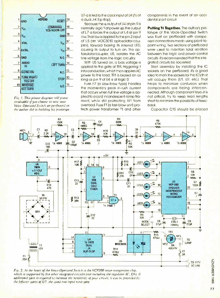
U5 MOC3010
R14
9 470f2 Wh
GND
U VCP200
RESET
Vce COMMAND/ YES -NO /ON -OFF
Vcc GND
XTAL
EXTAL
GND
AUDIO IN
Vcc
Vcc
N.C.
LEFT TURN
GO/NO-ON N.C.
TURN RIGHT/
YES -OFF
REVERSE/
NOT SURE
STOP
N.C,
Fig. I. This pinout diagram will prove invaluable if you choose to wire your Voice- Operated Switch on perfboard as the author did in building his prototype.
U7 -a is fed to the clock input of U4 (1/2 of a dual J -K flip -flop).
Because the Q output of U4 at pin 9 is
normally logic 1 at power up, the output of U7 -a forces the output of U4 at pin 9 low. That low is applied to the pin 2 input of U5 (an MOC3010 optoisolator/cou - pler), forward biasing its internal LED,
causing its output to turn on. The op- toisolator /coupler, U5, isolates the AC line voltage from the logic circuitry.
With U5 turned on, a bias voltage is
applied to the gate of TR1, triggering it into conduction, which then applies AC power to the load; TR1 is biased on as long as pin 9 of U4 is at logic O.
Fuse F2 (a slow -blow type) handles the momentary peak in -rush current that occurs when full line voltage is ap- plied to a cold incandescent -lamp fila- ment, while still protecting TR1 from overload. Fuse F1 (a fast -blow unit) pro- tects power transformer T1 and other
components in the event of an acci- dental short circuit.
Putting It Together. The author's pro- totype of the Voice -Operated Switch was built on perfboard with compo- nent connections made using point -to- point wiring. Two sections of perfboard were used to maintain total isolation between the logic and power -control circuits. It's recommended that the inte- grated circuits be socketed.
Start assembly by installing the IC
sockets on the perfboard; it's a good idea to mark the sockets for the IC's that will occupy them (U1, U2, etc.). That helps to minimize confusion when components are being intercon- nected. Although component layout is
not critical, try to keep lead lengths short to minimize the possibility of feed- back.
Capacitor C15 should be placed
MICI 3
C1 R2
2
11 2.2K
RI 150K
C15 1/6 4089
100
+IF
C3 .1
C2
F
^1 0pF I/ 4069
R3 1MEG V1h
1 C4
56pF
F14
680K -h-
50K
Vs 4069 'is 4069 1/6 4069
o
U6 7805
+5 VOLT REG.
G
~ 14 C 470
r
I
1A
50 PIV
+1
_J
F1
.25A
-.000 T1
(0000 12V
R12 10K 4
C13 _L.+
22
R13 39K
+5V
14 10
U2 558
DUAL OSO/
TIMER
13 2 1y -ir
' C12 ^ 22
R10 LEDI 27K
27K 01 LED2
5 1 14
2 U7-a
1/4 7400 7
C1 v .01
LED3 n LED4
0
--A' 12
14
6
7
11
U4 1/2 7479
DUAL JK
FLIP-FLOP
LED5 O 14
w 19
R9 10K
MODE SELECT
2
U3 VCP -200 SPEAKER
INDEPENDENT WORD
RECOGNIZER
4- 5
C8 - XTAL1 C9 27pFT 10MHz T27pF
3
R8
2 10K -JVw
R7 100K
C7 1 ^
20
18
6
'Oh F115
47052
TR1
G MT1
MT2 6A
400 PIV
Fig. 2. At the heart of the Voice -Operated Switch is the VCP200 voice -recognition chip, which is supported by five other integrated circuits (not including the regulator IC, U6). if additional gain is required to increase the sensitivity of your circuit, it can be provided by the leftover gates of U7, the quad two -input NAND gate.
TO
LAMP
F2
3A
o1 TO 117V
oT AC LINE
77
AmericanRadioHistory.Com
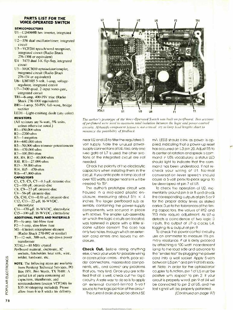
78
PARTS LIST FOR THE VOICE- OPERATED SWITCH
SEMICONDUCTORS U1-- CD4069B hex inverter, integrated
circuit U2 -556 dual oscillator /timer, integrated
circuit U3- VCP200 speech/word recognizer,
integrated circuit (Radio Shack 276 -1308 or equivalent)
U4 -7473 dual J -K flip -flop, integrated circuit
U5- MOC3010 optoisolator /coupler, integrated circuit (Radio Shack 276 -134 or equivalent)
U6- LM7805 5 -volt, I -amp, voltage - regulator, integrated circuit
U7 -7400 quad, 2 -input NAND -gate, integrated circuit
TRI-6 -amp, 400 -PIV triac (Radio Shack 276 -1000 equivalent)
BRI -I -amp, 50 -PIV, full -wave, bridge rectifier
LEDI- Light - emitting diode (any color) RESISTORS (All resistors are 1/4-watt, 5% units,
unless otherwise noted.) R1-150,000-ohm R2 -2200 -ohm R3- 1- megohm R4 680,000 -ohm R5- 50,000 -ohm trimmer potentiometer R6 470,000 -ohm R7- 100,000 -ohm R8, R9, R12- 10,000 -ohm RIO, R11- 27,000 -ohm R 13- 39,000 -ohm R14, RI5 -470 -ohm RI6 47,000 -ohm CAPACITORS CI, C3, C5, C7- 0.I -p.F, ceramic -disc C2- 100 -pF, ceramic -disc C8, C9- 27 -pF, ceramic -disc C4- 56-pF, ceramic -disc C6, CIO, C11- 0.01 -4 ceramic -disc C12, C13- 22 -p.l 16 -WVDC,
electrolytic C14-470 p.F. I6 -WVDC, electrolytic C15- 100 -11F, I6 -WVDC, electrolytic ADDITIONAL PARTS AND MATERIALS FI -% -amp, fast -blow fuse F2 -3 -amp, slow -blow fuse MI- Electret microphone element
(Radio Shack 270 -092 or similar) T1 -12 -volt, 300 -mA, step -down power
transformer XTALI -I0 -MHz crystal Perfboard material, enclosure, IC
sockets, fuseholder, heat sink, wire, solder, hardware, etc.
NOTE: The following items are available from Pershing Technical Services, PO Box 1951, Fort Worth, TX 76101: A partial kit of parts containing all capacitors, transformer, and semiconductors (except VCP200) for $35.00 (shipping included). Please allow from 6 to 8 weeks for delivery.
The author's prototype of the Voice- Operated Switch was built on perfboard. Two sections of perfboard were used to maintain total isolation between the logic and power- control circuits. Although component layout is not critical, try to keep lead lengths short to minimize the possibility of feedback.
near U2 and U3 to filter the regulated 5- volt supply. Note the unusual power - supply connections of U4. Also, only one NAND gate of U7 is used, the other sec- tions of the integrated circuit are not needed.
Check the polarity of the electrolytic capacitors when installing them in the circuit. If you anticipate a lamp load of over 100 watts, a larger heat sink will be needed for TRI.
The author's prototype circuit was housed in a mid -sized plastic en- closure, measuring about 5' x 4 inches. The larger perfboard sub -as- sembly, containing the power -supply components, was secured in place with screws. The smaller sub -assembly, on which the logic circuits are located, was fastened in place with a little sil-
icone rubber cement. The case has only two holes, through which an exten- sion cord enters and leaves the en- closure.
Check Out. Before doing anything else, check your work for possible wiring or construction errors -shorts, poor sol- der connections, misoriented compo- nents, etc., and correct any problems that you may find. Once you are satis- fied that all is well, check out the logic circuitry. A safe way to do so is to apply an external current -limited 5 -volt source to the logic portion of the circuit.
The current drain should be about 50
mA. LED3 should blink as power is ap- plied, indicating that a power -up reset has occurred on U3 pin 20. Adjust R5 to its center of rotation and speak a com- mand in U3's vocabulary; a status LED
should light to indicate that the com- mand has been understood. If not re- check your wiring of U1. Normal conversation -level speech should cause a 5 -volt peak -to -peak signal to be developed at pin 7 of U3.
To check the operation of U2, mo- mentarily ground pin 6 or 8 and check the corresponding outputs at pin 5 or 9 for the proper delay times as stated earlier. Due to the tolerances of the tim- ing capacitors, the values of R12 and R13 may require adjustment. As U7 -a detects a coincidence of two logic 0
inputs, the output of U7 -a clocks U4,
toggling its Q output at pin 9.
To check the power -control circuitry, use an ohmmeter to measure T1's pri- mary resistance. If all is okay, proceed by attaching a 100 -watt incandescent lamp to the load side and advance to the "smoke test" by plugging the power cord into a wall socket. Apply 5 -volts between U5 pin 1 and pin 9 of U4's sock- et. Note: in order for the optoisolator/ coupler to function, pin 1 of U5 must be positive with respect to pin 2. If your circuit is properly wired, pin 9 of U4 will be connected to pin 2 of U5, and the test signal will be properly polarized.
(Continued on page 97)
AmericanRadioHistory.Com
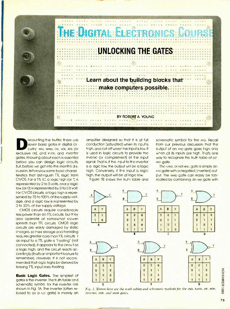
g a g e gegg Olt dege Meg, *Se
se va a
ivIRONI _ p. . a ., a a m a a a a a.a a a a a r x a e a e w e. a. a a a a a rt= a» Y
AV e
Agog AO a,_ eg mR:yUNLOCKINGTHEGATES Verge At Agee e ese ye es, v
Fts a s x m egg
a a ta
Learn about the building blocks that g
: : . make computers possible, : g a g e gee : es
W A+ e a gegt deg e a a,. .. ... . .. .. a a k A Se AS As M ß a
ge a a . : a a a g w a g e s e a s .. « a « g g e e g a g æ Vs, ., « s u. e« eSts a egelegate e a a gege a a m , a a a e s e a e a e g g e a a a s A g a a e m p s As a a e a a a a e a a. a e -c æ a a ì a a gee s a a a® a s a a o a
.p:.kgßu.:aa.#.w3,::.eBa3a3.a3:sa3&ageáe
.. egg ae ba Agee a.aeaaae. «
vg e
eaaea ageea
BY ROBERT A. YOUNG egg vs
Discounting the buffer, there are seven basic gates in digital cir- cuitry: AND, NAND, OR, NOR, XOR (or
exclusive OR), and XNOR, and inverter gates. Knowing about each is essential before you can design logic circuits. But, before we get into this month's dis- cussion, let's review some basic charac- teristics that distinguish TTL logic from CMOS. For a TTL IC, a logic high (or 1) is
represented by 2 to 5 volts, and a logic low (or 0) is represented by 0 to 0.8 volt. For CMOS circuits, a logic high is repre- sented by 70 to 100% of the supply volt- age, and a logic low is represented by 0 to 30% of the supply voltage.
CMOS circuits require considerably less power than do TTL circuits, but they also operate at somewhat slower speeds than TTL circuits. CMOS logic circuits are easily damaged by static charges, so their storage and handling requires greater care than TTL circuits. If
an input to a TTL gate is "floating" (not connected), it appears to the circuit as a logic high, and the circuit reacts ac- cordingly (that's an important feature to remember). However, it is not recom- mended that logic highs be derived by leaving TTL input lines floating.
Basic Logic Gates. The simplest of gates is the inverter. The truth table and schematic symbol for the inverter are shown in Fig. 1A. The inverter (often re- ferred to as a NOT gate) is merely an
amplifier designed so that it is at full conduction (saturated) when its input is
high, and cut -off when the input is low. It
is used in logic circuits to provide the inverse (or complement) of the input signal. That is, if the input to the inverter is a logic low, the output will be a logic high. Conversely, if the input is logic high, the output will be at logic low.
Figure 1B shows the truth table and
schematic symbol for the AND. Recall from our previous discussion that the output of an AND gate goes high only when all its inputs are high. That's one way to recognize the truth table of an AND gate.
The NAND, or NOT -AND, gate is simply an AND gate with a negated (inverted) out- put. The NAND gate can easily be fab- ricated by combining an AND gate with
A Y
o
A
A B Y
o
o
o
o
o
o
o
B
A B Y
o
o
o
A A
B B Y
A B Y
o
o
o
o
o
o
o
A B Y
o
o
o
o
o
o
A B Y
o
o
o
o
o
D
A
B )DC)17 A B Y
o
o
o
o
o
o
E F G
Fig. 1. Shown here are the truth tables and schematic symbols for the AND, NAND, OR, NOR,
inverter, XOR, and XNOR gates.
79
AmericanRadioHistory.Com
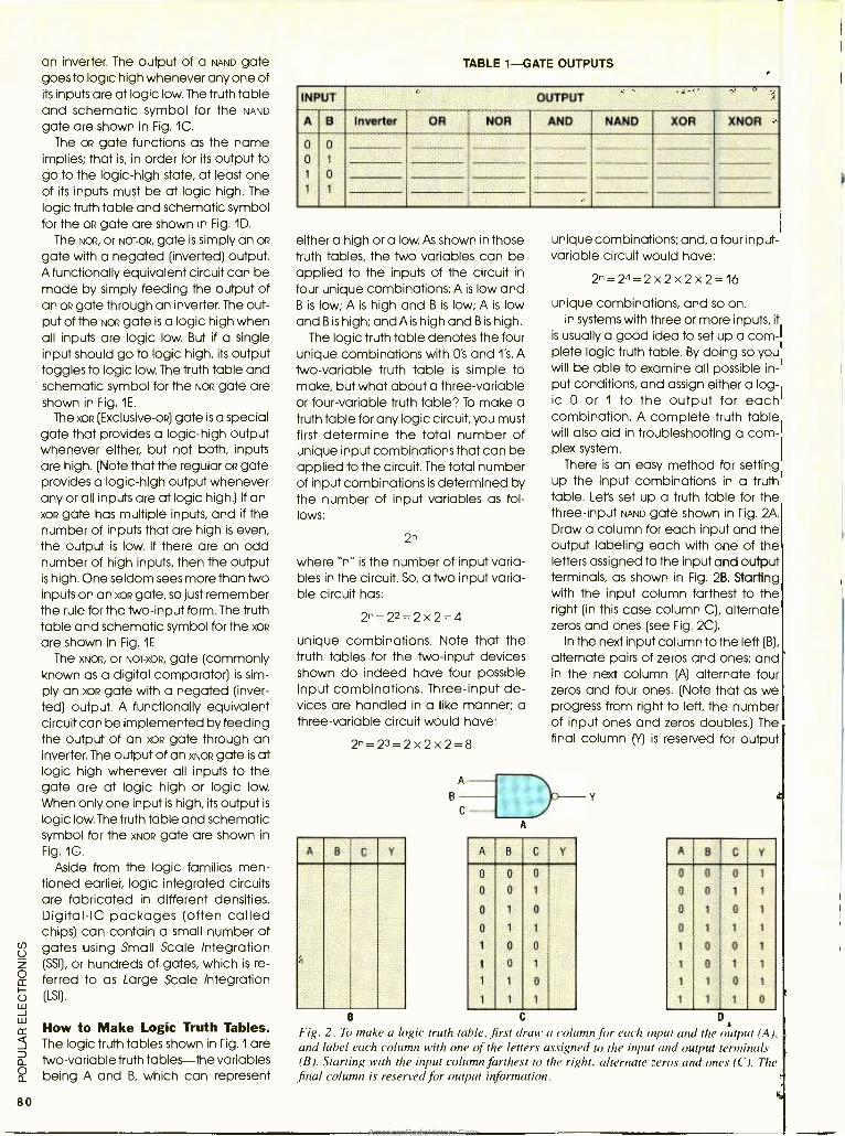
80
an inverter. The output of a NAND gate goes to logic high whenever any one of its inputs are at logic low. The truth table and schematic symbol for the NAND
gate are shown in Fig. 1C.
The op gate functions as the name implies; that is, in order for its output to go to the logic -high state, at least one of its inputs must be at logic high. The logic truth table and schematic symbol for the op gate are shown in Fig. 1D.
The NOR, or NOT -OR, gate is simply an OR
gate with a negated (inverted) output. A functionally equivalent circuit can be made by simply feeding the output of an OR gate through an inverter. The out- put of the NOR gate is a logic high when all inputs are logic low. But if a single input should go to logic high, its output toggles to logic low. The truth table and schematic symbol for the NOR gate are shown in Fig. 1E.
The xoR (Exclusive-op) gate is a special gate that provides a logic -high output whenever either, but not both, inputs are high. (Note that the regular oR gate provides a logic -high output whenever any or all inputs are at logic high.) If an XOR gate has multiple inputs, and if the number of inputs that are high is even, the output is low. If there are an odd number of high inputs, then the output is high. One seldom sees more than two inputs on an xoR gate, so just remember the rule for the Iwo-input form. The truth table and schematic symbol for the XOR
are shown in Fig. IF The XNOR, or NOT -XOR, gate (commonly
known as a digital comparator) is sim- ply an XOR gate with a negated (inver- ted) output. A functionally equivalent circuit can be implemented by feeding the output of an xoR gate through an inverter. The output of an XNOR gate is at logic high whenever all inputs to the gate are at logic high or logic low. When only one input is high, its output is
logic low. The truth table and schematic symbol for the XNOR gate are shown in Fig. 1G.
Aside from the logic families men- tioned earlier, logic integrated circuits are fabricated in different densities. Digital -IC packages (often called chips) can contain a small number of gates using Small Scale Integration (SSI), or hundreds of gates, which is re- ferred to as Large Scale Integration (LSI).
How to Make Logic Truth Tables. The logic truth tables shown in Hg. 1 are two -variable truth tables -the variables being A and B, which can represent
TABLE 1 -GATE OUTPUTS
INPUT OUTPUT
A B Inverter OR NOR AND NAND XOR XNOR
0
0
1
1
0
1
0
1
either a high or a low. As shown in those truth tables, the Iwo variables can be applied to the inputs of the circuit in
four unique combinations: A is low and B is low; A is high and B is low; A is low and B is high; and A is high and B is high.
The logic truth table denotes the four unique combinations with 0's and l's. A Iwo-variable truth table is simple to make, but what about a three -variable or four -variable truth table? To make a truth table for any logic circuit, you must first determine the total number of unique input combinations that can be applied to the circuit. The total number of input combinations is determined by the number of input variables as fol- lows:
2n
where "n" is the number of input varia- bles in the circuit. So, a two input varia- ble circuit has:
2 ̂ =22 =2x2 =4
unique combinations. Note that the truth tables for the two -input devices shown do indeed have four possible input combinations. Three -input de- vices are handled in a like manner; a three -variable circuit would have:
2 ̂ = 23= 2x2x2 =8
B
A B C Y
B
Fig. 2. To make a logic truth table, first draw a column for each input and the output (A), and label each column with one of the letters assigned to the input and output terminals (B). Starting with the input column farthest to the right, alternate zeros and ones (C). The final column is reserved for output information.
unique combinations; and, a four input - variable circuit would have:
2n= 24= 2x2x2x2 =16
unique combinations, and so on. In systems with three or more inputs, it
is usually a good idea to set up a com- plete logic truth table. By doing so you will be able to examine all possible in- put conditions, and assign either a log- ic 0 or 1 to the output for each combination. A complete truth table will also aid in troubleshooting a com- plex system.
There is an easy method for setting up the input combinations in a truth table. Let's set up a truth table for the three -input NAND gate shown in Fig. 2A. Draw a column for each input and the output labeling each with one of the letters assigned to the input and output terminals, as shown in Fig. 2B. Starting with the input column farthest to the right (in this case column C), alternate zeros and ones (see Fig. 2C).
In the next input column to the left (B),
alternate pairs of zeros and ones; and in the next column (A) alternate four zeros and four ones. (Note that as we progress from right to left, the number of input ones and zeros doubles.) The final column M is reserved for output
A B C Y
o o o
0 o 1
0 1 o
o 1 1
1 o o
1 o 1
1 1 0
1 1 1
A B C Y
o o o 1
o o 1 1
o 1 o 1
o 1 1 1
1 0 0 1
1 o 1 1
1 1 o 1
1 1 1 o
D
AmericanRadioHistory.Com
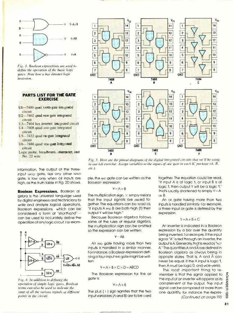
A
B
A
B
A
J
Y Y=A+B
Y Y=AB
Y Y=A
Fig. 3. Boolean expressions are used to define the operation of the basic logic gates. Note how a bar denotes logic inversion.
PARTS LIST FOR THE GATE EXERCISE
U1 -7400 quad NAND -gate integrated circuit
U2 -7402 quad NoR -gate integrated circuit
U3 -7404 hex inverter, integrated circuit U4 -7408 quad AND -gate integrated
circuit U5 -7432 quad OR-gate integrated
circuit U6 -7486 quad xoR -gate integrated
circuit Logic probe, breadboard, ohmmeter, and
No. 22 wire
information. The output of the three - input NAND gate, like any other NAND
gate, is low only when all inputs are high, as the truth table in Fig. 2D shows.
Boolean Expressions. Boolean al- gebra is the universal language used by digital engineers and technicians to write and analyze logical operations. Boolean expressions -which can be considered a form of "shorthand" - can be used to accurately define the operation of any logic circuit. For exam-
B A
Fig. 4. In addition to defining the operation of simple logic gates, Boolean terms can also be used to indicate the state of all the various signals at different points in the circuit.
-1 T
l7
GND
7
GND
r-
r r-
Vcc
14
7408 A
7432 D
V,
10
9
8 7
GND
7400 B
LB
7
GND
Vcc
14
L13 12
11 4
10 5 AE
7404 C
7402 E
7
GND
.
Vcc
14
13
8 1
7486
F
Fig. 5. Here are the pinout diagrams of the digital integrated circuits that we'll be using in our lab exercise. Assign variables to the inputs of one gate in each IC package (A, B,
etc.).
pie, the AND gate can be written as the Boolean expression:
Y =AxB
The multiplication sign, x simply means that the input signals are ANDed to- gether. The equations can be read as,
"if inputs A AND B are both high (1) then output Y will be high."
Because Boolean algebra follows some of the rules of regular algebra, the multiplication sign can be omitted so the expression can be written:
Y = AB
An AND gate having more than Iwo inputs is handled in a similar manner. For instance, a Boolean expression defi- ning a four -input AND gate might be writ- ten:
Y= AxBxCxD =ABCD
The Boolean expression for the OR
gate is:
Y=A+B
The plus ( +) sign signifies that the two input variables (A and B) are to be owed
together. The equation could be read, "if input A is at logic 1, or input B is at logic 1, then output Y will be a logic 1."
That's usually shortened to simply Y = A OR B.
An oa gate having more than two inputs is handled similarly. For example, a three -input OR gate is defined by the expression:
Y=A+B+C
An inverter is indicated in a Boolean expression by a bar over the quantity being inverted. For example, if the input signal "A" is fed through an inverter, the output is A. Generally, that is read as "NOT
A." The quantities A and A are defined in
Boolean algebra as always being in
opposite states. That is, A and A can never be equal. If the A input is logic 1,
then A must be logic 0, and vice -versa. The most important thing to re-
member is that the signal applied to the input of an inverter will appear as its
complement at the output. The input signal can be comprised of more than one quantity, for instance the expres-
(Continued on page 99)
81
AmericanRadioHistory.Com
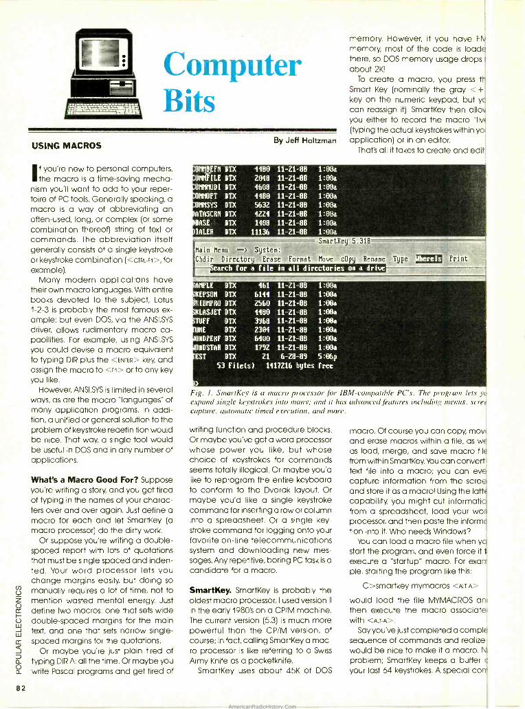
OMMDEFn DTX 4980 11 -21 -88 1:00a
OMMFILE DTX 2098 11 -21 -88 1:OOa
OMMMODI DTX 4608 11 -21 -80 1:OOa
OMMOPT DTX 4980 11 -Z1 -88 1:O0a
OMMSYS DTX 5632 11 -21 -88 1:00a
ATASCRM DTX 4224 11 -21 -88 1:OOa
BASE DTX 1408 11 -21 -88 1:00a
IALER DTX 11136 11 -21 -88 1:O0a
SmartRey 5.31B
82
Computer Bits
USING MACROS
If you're new to personal computers, the macro is a time -saving mecha-
nism you'll want to add to your reper- toire of PC tools. Generally speaking, a macro is a way of abbreviating an often -used, long, or complex (or some combination thereof) string of text or commands. The abbreviation itself generally consists of a single keystroke or keystroke combination (<cTRL -ri >, for example).
Many modern applications have their own macro languages. With entire books devoted to the subject, Lotus 1 -2 -3 is probably the most famous ex- ample; but even DOS, via the ANSI.SYS
driver, allows rudimentary macro ca- pabilities. For example, using ANSI.SYS
you could devise a macro equivalent to typing DIR plus the <ENTER> key, and assign the macro to <F1> or to any key you like.
However, ANSI.SYS is limited in several ways, as are the macro "languages" of many application programs. In addi- tion, a unified or general solution to the problem of keystroke redefinition would be nice. That way, a single tool would be useful in DOS and in any number of applications.
What's a Macro Good For? Suppose you're writing a story, and you get tired of typing in the names of your charac- ters over and over again. Just define a macro for each and let SmartKey (a macro processor) do the dirty work.
Or suppose you're writing a double - spaced report with lots of quotations that must be single spaced and inden- ted. Your word processor lets you change margins easily, but doing so manually requires a lot of time, not to mention wasted mental energy. Just define two macros: one that sets wide double- spaced margins for the main text, and one that sets narrow single - spaced margins for the quotations.
Or maybe you're just plain tired of typing DIR A: all the time. Or maybe you write Pascal programs and get tired of
By Jeff Holtzman
memory. However, if you have E
memory, most of the code is load_ there, so DOS memory usage drops about 2K!
To create a macro, you press t Smart Key (nominally the gray < + key on the numeric keypad, but yc
can reassign it). SmartKey then allo you either to record the macro "liv (typing the actual keystrokes within yo application) or in an editor.
That's all it takes to create and edit
Main Menu => System:
Chdir Directory Erase Format Move cOpy Rename
earch for a file in all directories on a drive
AMPLE DTX 461 11 -21 -88 1:OOa
KEPSON DTX 6144 11 -Z1 -88 1:00a
KIBMPBO DTX 2560 11 -Z1 -88 1:00a
KLASJET DIX 4480 11 -Z1 -88 1:00a
TUFF DTX 3968 11 -21 -88 1:00a
UNE DTX 2304 11 -21 -88 1:00a
IRDPERF DTX 6400 11 -21 -88 1:00a
URDSTAR DTX 1792 11 -21 -88 1:00a
EST DTX 21 6 -28 -89 5:06p
53 File(s) 1417Z16 bytes free
i>
Fig. I. SmartKey is a macro processor for IBM- compatible PC's. The program lets y expand single keystrokes into many; and it has advanced features including menus, sere capture, automatic timed execution, and more.
writing function and procedure blocks. Or maybe you've got a word processor whose power you like, but whose choice of keystrokes for commands seems totally illogical. Or maybe you'd like to reprogram the entire keyboard to conform to the Dvorak layout. Or maybe you'd like a single keystroke command for inserting a row or column into a spreadsheet. Or a single key- stroke command for logging onto your favorite on -line telecommunications system and downloading new mes- sages. Any repetitive, boring PC task is a candidate for a macro.
SmartKey. SmartKey is probably the oldest macro processor; I used version II
in the early 1980's on a CP /M machine. The current version (5.3) is much more powerful than the CP /M version, of course; in fact, calling SmartKey a mac- ro processor is like referring to a Swiss
Army Knife as a pocketknife. SmartKey uses about 45K of DOS
macro. Of course you can copy, may and erase macros within a file, as we as load, merge, and save macro file
from within SmartKey. You can convert text file into a macro; you can eve capture information from the scre and store it as a macro! Using the lath capability, you might cut informatio from a spreadsheet, load your wor processor, and then paste the informc tion into it. Who needs Windows?
You can load a macro file when yo start the program, and even force it t
execute a "startup" macro. For exan- ple, starting the program like this:
C >smartkey mymacros <ALTA>
would load the file MYMACROS an then execute the macro associate with <ALT -A >.
Say you've just completed a comp) sequence of commands and realize would be nice to make it a macro. problem; SmartKey keeps a buffer your last 64 keystrokes. A special co
AmericanRadioHistory.Com
mand converts the buffer into a macro that you're free to edit with the usual tools.
SmartKey macros can also get fancy. For example, you can halt a macro temporarily, allow the user to enter some information, and then continue. You can allow the user to type any number of keystrokes, or just a specific number of keystrokes; you can even force input to be a valid time or date. Going the other way, you can tell SmartKey to expand time and date strings in a macro. With that ability, you could press a "smart" key in your word processor and have formatted time and date strings entered into your doc- ument automatically.
Other advanced macro commands allow you to send strings to your printer, thus enabling special fonts, etc. Sim- ilarly, you can send strings to a modem, thus using it as an autodialer.
VENDOR INFORMATION
SmartKey, version 5.3 ($89.95) Command Software Systems, Inc. 28990 PC Highway., Suite 208 Malibu, CA 90265 800/423-9147; 213/457-1789
One of SmartKey's most powerful fea- tures is what the company calls an OmniKey, a means of executing a mac- ro automatically when a macro file is
loaded, at a specific time of day, after a specific time interval, or when a specif- ic string of text appears on the screen. For example, using the time -interval op- tion, you could force your word pro- cessor to back up your work every five minutes. You can have a total of four OmniKeys in memory at one time.
You can also include conditional pro- cessing in your macros. Using the "Until" command, you can cause a macro to pause until a specific time of day or until a specific text string appears on the screen. The "If' command allows a macro to execute in one of two ways, depending on whether a specified text string appears on the screen. The com- mands "If and Until" are useful, but would be even more useful if you could specify the exact screen location at which the desired text should appear.
SmartKey includes several other fea- tures that take it beyond the realm of macro processing. For one, the pro- gram includes its own set of DOS func- tions: making and changing directo-
ries; copying, moving, erasing, typing, printing, and locdting files (by name, by a text string, or both); and formatting floppy disks.
SmartKey also includes facilities for generating on- screen windows and menus. A window has a border, can appear anywhere on the screen in any size, and text can be placed anywhere within a window. You can also create a menu inside a window, and force dif- ferent actions to occur depending on which item a user chooses. With the menu facility, you could create your own on -line help system for any pro- gram, a pop -up printer controller (sev-
eral examples of these are supplied), or even a DOS shell.
In addition, SmartKey includes sev- eral utility programs: one allows you to "move" keyboard keys, another en- crypts and decrypts files, another blanks the screen after a specified period of inactivity, and another, called SmartPrint, that acts as macro pro- cessor for your printer. Several public domain programs (DOSEDIT and a sorted directory lister) that make life with DOS a little more pleasant are also included.
$350
THINK TANK 53 PAGES, OVER 130
PROJECTS!
SIMPLE, EASY-TO-BUILD AND USEFUL IDEAS FOR YOUR
HOME, HOBBY, CAR.
HERE'S THE ANSWER to that eternal question among electronics hobbyists - "What will I do ?" In WELS' THINK TANK you'll find over 53 pages jam -packed with over 130 one- evening projects that will keep you ab- sorbed. These are tantalizing devices that you can quickly put together and then use immediately. There are projects for your car, your home, your work bench, other hobbys, such as photography, music, and stereo. Telephone projects, light controls, and a vast assortment of miscellaneous do- it- yourself items. Flipping through the pages of this book, the question becomes "Which one will I
start with!
THE THINK TANK originally appeared in
rr
Hands -On Electronics Magazine, and imme- diately won a good deal of reader accep- tance. The mail poured in as readers offered their own circuits or asked for assistance with electronics projects they worked on.
WHAT KIND OF PROJECTS will you find in the WELS' THINK TANK BOOK? The in- dex, which occupies the entire back page, lists them. Choose from nearly a dozen am- plifiers, an assortment of automotive projects from automatic parking lights to electronic air horns, battery chargers to battery monitors. You'll find fuzz boxes for your guitar to a trem- olo unit. A darkroom timer for you photo buffs. And at a price of only $3.50, you can't go wrong!
THINK TANK -Circuits for Experimenters and Project Builders!
169 -Please send one copy of THINK TANK at $3.50. Shipping $1.25 (U.S. and Canada only).
169 -Please send copies of THINK TANK. Total cost is sum of copy price and shipping cost multiplied by number of copies ordered.
AlloH
Please print
(Name)
(Street Address)
(City) (State)
Detach and mail today: Popular Electronics Bookstore P.O. Box 4079 Farmingdale, NY 11735
All Payment must be in U.S. (Zip) Funds!
P-1189 83
AmericanRadioHistory.Com
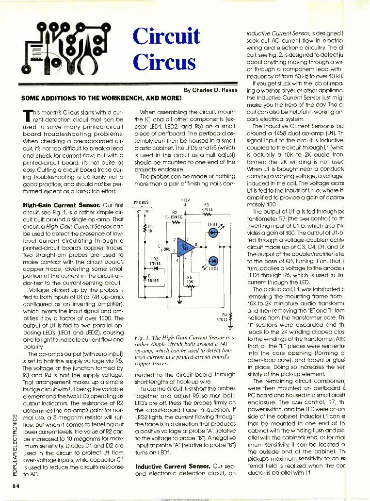
84
Circuit Circus
SOME ADDITIONS TO THE WORKBENCH, AND MORE!
his month's Circus starts with a cur- rent- detection circuit that can be
used to solve many printed- circuit board troubleshooting problems. When checking a breadboarded cir- cuit, it's not too difficult to break a lead and check for current flow; but with a printed -circuit board, it's not quite as easy. Cutting a circuit board trace dur- ing troubleshooting is certainly not a good practice, and should not be per- formed except as a last -ditch effort.
High -Gain Current Sensor. Our first circuit, see Fig. 1, is a rather simple cir- cuit built around a single op -amp. That circuit, a High -Gain Current Sensor, can be used to detect the presence of low - level current circulating through a printed- circuit board's copper traces. Two straight -pin probes are used to make contact with the circuit board's copper trace, diverting some small portion of the current in the circuit -un- der -test to the current -sensing circuit.
Voltage picked up by the probes is
fed to both inputs of U1 (a 741 op-amp, configured as an inverting amplifier), which inverts the input signal and am- plifies it by a factor of over 1000. The
output of U1 is fed to two parallel -op- posing LED's (LEDI and LED2), causing one to light to indicate current flow and polarity.
The op -amp's output (with zero input) is set to half the supply voltage via R5.
The voltage at the junction formed by R3 and R4 is half the supply voltage. That arrangement makes up a simple bridge circuit with U1 being the variable element and the Iwo LED's operating as
output indicators. The resistance of R2
determines the op -amp's gain; for nor- mal use, a 5- megohm resistor will suf-
fice, but when it comes to ferreting out lower current levels, the value of R2 can be increased to 10 megohms for max- imum sensitivity. Diodes D1 and D2 are used in the circuit to protect U1 from over -voltage inputs, while capacitor C1
is used to reduce the circuit's response to AC.
By Charles D. Rakes
When assembling the circuit, mount the IC and all other components (ex-
cept LEDI, LED2, and R5) on a small piece of perfboard. The perfboard as-
sembly can then be housed in a small plastic cabinet. The LED's and R5 (which is used in this circuit as a null adjust) should be mounted to one end of the project's enclosure.
The probes can be made of nothing more than a pair of finishing nails con-
R4
47052
Fig. 1. The High -Gain Current Sensor is a rather simple circuit built around a 741
op -amp, which can be used to detect low - level current in a printed -circuit board's copper traces.
nected to the circuit board through short lengths of hook -up wire.
To use the circuit, first short the probes together and adjust R5 so that both LED's are off. Press the probes firmly on the circuit -board trace in question. If
LED2 lights, the current flowing through the trace is in a direction that produces a positive voltage at probe "A" (relative to the voltage to probe "B "). A negative input at probe "A" (relative to probe "B'l turns on LEDI.
Inductive Current Sensor. Our sec- ond electronic detection circuit, an
Inductive Current Sensor, is designed I
seek out AC current flow in electric wiring and electronic circuitry. The d cuit, see Fig. 2, is designed to detect ju about anything moving through a win or through a component lead with frequency of from 60 Hz to over 10 kH;
If you get stuck with the job of repal ing a washer, dryer, or other appliance the Inductive Current Sensor just migl make you the hero of the day. The d cuit can also be helpful in working on car's electrical system.
The Inductive Current Sensor is bu around a 1458 dual op -amp (U1). Th
signal input to the circuit is inductive coupled to the circuit through LI (whic is actually a 10K to 2K audio tran former; the 2K winding is not usec When L1 is brought near a conduct, carrying a varying voltage, a voltage induced in the coil. The voltage acrd L1 is fed to the inputs of U1 -a, where it amplified to provide a gain of appro mately 100.
The output of U1 -a is fed through pc
tentiometer R7 (the GAIN control) to it- inverting input of U1 -b, which also prc
vides a gain of 100. The output of U1 -b fed through a voltage -doubler /rectifk circuit made up of C3, C4, D1, and D
The output of the doubler /rectifier is fe to the base of Q1, turning it on. That, turn, applies a voltage to the anode LEDI through R6, which is used to lirr current through the LED.
The pickup coil, L1, was fabricated C
removing the mounting frame from 10K -to -2K miniature audio transforme, and then removing the "E" and "I" lam nations from the transformer core. Th
"I" sections were discarded and th leads to the 2K winding clipped clos to the windings of the transformer. AffE
that, all the "E" pieces were reinserte into the core opening (forming a open -loop core), and taped or glue in place. Doing so increases the ser sitivity of the pick -up element.
The remaining circuit componen were then mounted on perfboard c
PC board and housed in a small plasti enclosure. The GAIN control, R7, th power switch, and the LED were on on side of the cabinet. Inductor L1 can e ther be mounted in one end of tl' cabinet with the winding flush and pal allel with the cabinet's end, or for mace
imum sensitivity, it can be located o the outside end of the cabinet. Thl
pickup's maximum sensitivity to an e ternal field is realized when the cor ductor is parallel with L1.
AmericanRadioHistory.Com
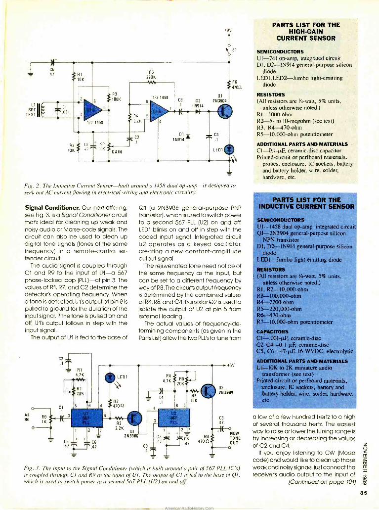
Fig. 2. The Inductive Current Sensor -built around a 1458 dual op- amp-is designed to
seek out AC current flowing in electrical wiring and electronic circuitry.
Signal Conditioner. Our next offering, see Fig. 3, is a Signal Conditioner circuit that's ideal for cleaning up weak and noisy audio or Morse -code signals. The circuit can also be used to clean up digital tone signals (tones of the same frequency) in a remote -control ex- tender circuit.
The audio signal is coupled through Cl and R9 to the input of U1-a 567 phase -locked loop (PLL) -at pin 3. The values of R1, R7, and C2 determine the detector's operating frequency. When a tone is detected, UI's output at pin 8 is
pulled to ground for the duration of the input signal. If the tone is pulsed on and off, UI's output follows in step with the input signal.
The output of U1 is fed to the base of
AF IN
R9 1K
01 (a 2N3906 general -purpose PNP
transistor), which is used to switch power to a second 567 PLL (U2) on and off. LEDI blinks on and off in step with the coded input signal. Integrated circuit U2 operates as a keyed oscillator, creating a new constant -amplitude output signal.
The rejuvenated tone need not be of the same frequency as the input, but can be set to a different frequency by way of R8. The circuit's output frequency is determined by the combined values of R4, R8, and C4. Transistor Q2 is used to isolate the output of U2 at pin 5 from external loading.
The actual values of frequency -de- termining components (as given in the Parts List) allow the two PLL's to tune from
C3
R4
4.7K
C4
.1
1 2 7
C7 C8
R6
47 .47 470SZ
R5
10K
02
+5V
2N 3904
C9 47
+ NEW TONE OUT
c o
Fig. 3. The input to the Signal Conditioner (which is built around a pair of 567 PLL IC's) is coupled through CI and R9 to the input of UI. The output of Ul is fed to the base of QI, which is used to switch power to a second 567 PLL (U2) on and off
PARTS LIST FOR THE HIGH -GAIN
CURRENT SENSOR
SEMICONDUCTORS UI -741 op -amp, integrated circuit DI, D2-1N914 general -purpose silicon
diode LEDI,LED2 -Jumbo light- emitting
diode
RESISTORS (All resistors are 1/4 -watt, 5% units,
unless otherwise noted.) R1-1000-ohm R2 -5- to 10- megohm (see text) R3, R4-470-ohm R5- 10,000 -ohm potentiometer
ADDITIONAL PARTS AND MATERIALS C1- 0.1 -µF, ceramic -disc capacitor Printed- circuit or perfboard materials,
probes, enclosure, IC sockets, battery and battery holder, wire, solder, hardware, etc.
PARTS LIST FOR THE INDUCTIVE CURRENT SENSOR
SEMICONDUCTORS UI -1458 dual op -amp. integrated circuit QI- 2N3904 general- purpose silicon
NPN transistor DI, D2-1N914 general -purpose silicon.
diode LED1-Jumbo 1
RESISTORS (All resistors are 1/4-watt, 5% units,
unless otherwise noted.) R1, R2- 10,000 -ohm R3--- 100,000 -ohm- R4 -2200 -ohm R5- 220,000 -ohms R6 470 -ohm R7- I0,000 -ohm potentiometer.
CAPACITORS C1- .001 -p F, ceramic -disc C2- C4-- -0.1 -p F, ceramic -disc CS, C6-- 47 -µF, 16 -WVDC. electrolytic
ADDITIONAL PARTS AND MATERIALS L1 -10K to 2K miniature audio
transformer (see text) Printed -circuit or perfboard materials,
enclosure, IC sockets, battery and battery holder, wire, solder, hardware tc.
a low of a few hundred hertz to a high of several thousand hertz. The easiest way to raise or lower the tuning range is
by increasing or decreasing the values of C2 and C4.
if you enjoy listening to CW (Morse code) and would like to clean up those weak and noisy signals, just connect the receiver's audio output to the input of
(Continued on page 101)
AmericanRadioHistory.Com
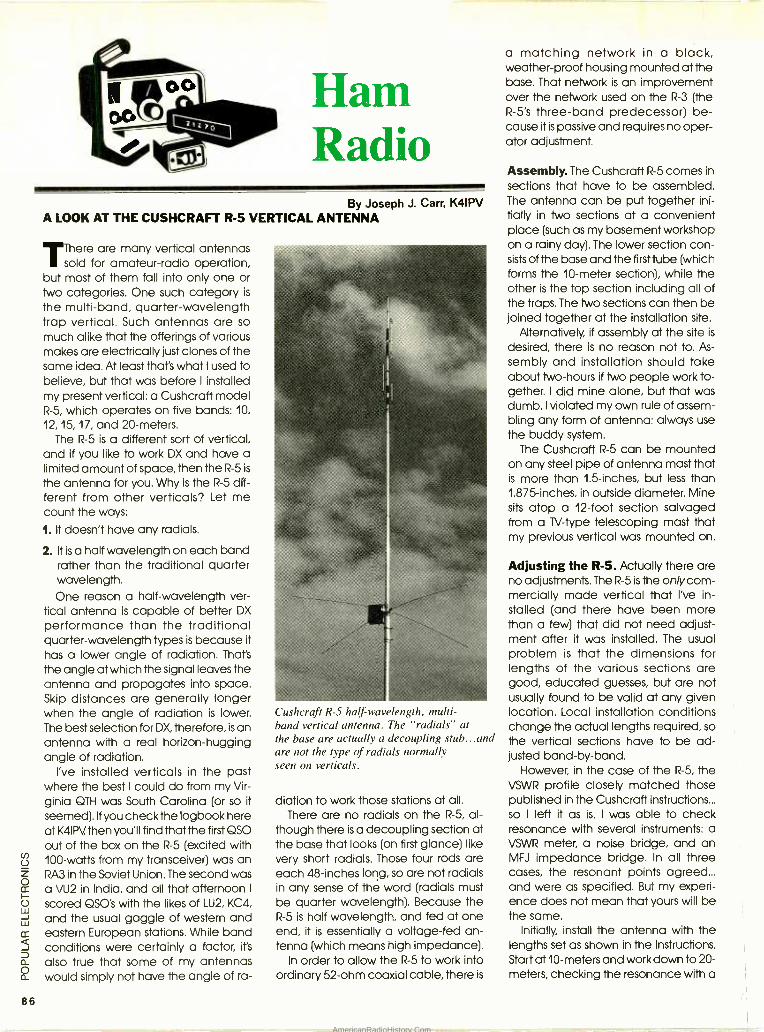
Ham Radio
86
By Joseph J. Carr, K4IPV A LOOK AT THE CUSHCRAFT R -5 VERTICAL ANTENNA
There are many vertical antennas sold for amateur -radio operation,
but most of them fall into only one or two categories. One such category is
the multi -band, quarter -wavelength trap vertical. Such antennas are so much alike that the offerings of various makes are electrically just clones of the same idea. At least that's what I used to believe, but that was before I installed my present vertical: a Cushcraff model R -5, which operates on five bands: 10,
12, 15, 17, and 20- meters. The R -5 is a different sort of vertical,
and if you like to work DX and have a limited amount of space, then the R -5 is
the antenna for you. Why is the R -5 dff- ferent from other verticals? Let me count the ways:
1. It doesn't have any radials.
2. It is a half wavelength on each band rather than the traditional quarter wavelength. One reason a half -wavelength ver-
tical antenna is capable of better DX
performance than the traditional quarter -wavelength types is because it has a lower angle of radiation. That's
the angle at which the signal leaves the antenna and propagates into space. Skip distances are generally longer when the angle of radiation is lower. The best selection for DX, therefore, is an antenna with a real horizon -hugging angle of radiation.
I've installed verticals in the past where the best I could do from my Vir- ginia 9TH was South Carolina (or so it
seemed). If you check the logbook here at K4IPV then you'll find that the first 9SO out of the box on the R -5 (excited with 100 -watts from my transceiver) was an RA3 in the Soviet Union. The second was a VU2 in India, and all that afternoon I
scored 9SO's with the likes of LU2, KC4,
and the usual gaggle of western and eastern European stations. While band conditions were certainly a factor, it's
also true that some of my antennas would simply not have the angle of ra-
Cushcraft R -5 half-wavelength, multi - band vertical antenna. The "radials" at the base are actually a decoupling stub...and are not the type of radials normally seen on verticals.
diation to work those stations at all. There are no radials on the R -5, al-
though there is a decoupling section at the base that looks (on first glance) like very short radials. Those four rods are each 48- inches long, so are not radials in any sense of the word (radials must be quarter wavelength). Because the R -5 is half wavelength, and fed at one end, it is essentially a voltage -fed an- tenna (which means high impedance).
In order to allow the R -5 to work into ordinary 52 -ohm coaxial cable, there is
a matching network in a black, weather -proof housing mounted at the base. That network is an improvement over the network used on the R -3 (the R -5's three -band predecessor) be- cause it is passive and requires no oper- ator adjustment.
Assembly. The Cushcraff R -5 comes in
sections that have to be assembled. The antenna can be put together ini- tially in two sections at a convenient place (such as my basement workshop on a rainy day). The lower section con- sists of the base and the first tube (which forms the 10 -meter section), while the other is the top section including all of the traps. The two sections can then be joined together at the installation site.
Alternatively, if assembly at the site is
desired, there is no reason not to. As-
sembly and installation should take about two -hours if two people work to- gether. I did mine alone, but that was dumb. I violated my own rule of assem- bling any form of antenna: always use the buddy system.
The Cushcraff R -5 can be mounted on any steel pipe of antenna mast that is more than 1.5- inches, but less than 1.875- inches, in outside diameter. Mine sits atop a 12 -foot section salvaged from a 1V-type telescoping mast that my previous vertical was mounted on.
Adjusting the R -5. Actually there are no adjustments. The R -5 is the only corn- mercially made vertical that I've in- stalled (and there have been more than a few) that did not need adjust- ment after it was installed. The usual problem is that the dimensions for lengths of the various sections are good, educated guesses, but are not usually found to be valid at any given location. Local installation conditions change the actual lengths required, so the vertical sections have to be ad- justed band -by -band.
However, in the case of the R -5, the VSWR profile closely matched those published in the Cushcraff instructions... so I left it as is. I was able to check resonance with several instruments: a VSWR meter, a noise bridge, and an MFJ impedance bridge. In all three cases, the resonant points agreed... and were as specified. But my experi- ence does not mean that yours will be the same.
Initially, install the antenna with the lengths set as shown in the instructions. Start at 10- meters and work down to 20- meters, checking the resonance with a
AmericanRadioHistory.Com
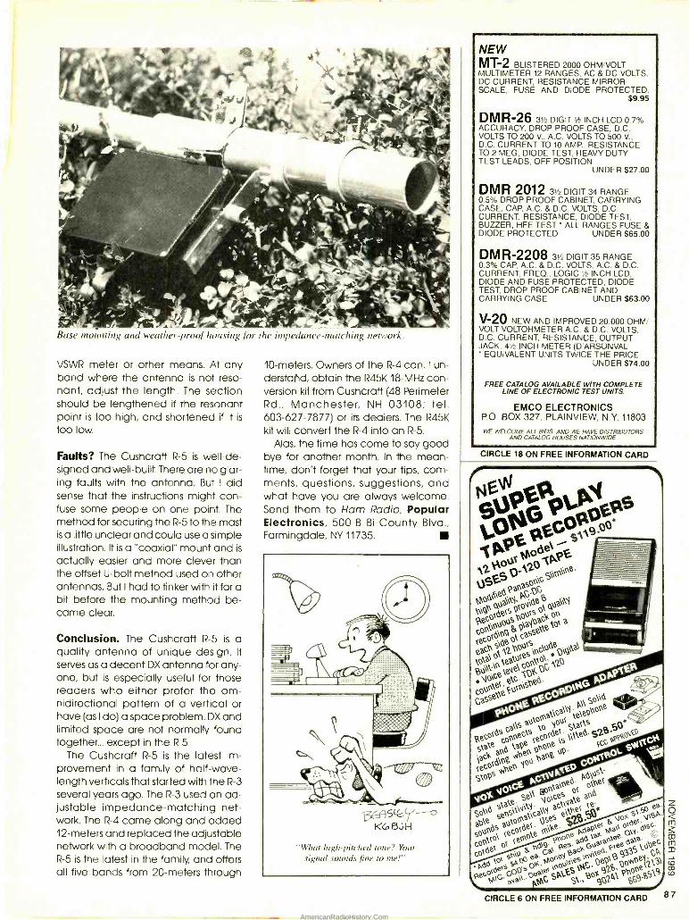
Nv SpN 1 ix p
two N o 1pP 12 0.12 tc°t°e, VgES as0c S
0060 q á qaCrl h9 woos
0040", cs ° p1 h° k °(N
p° d9 tass e t0\ a
ách°s`d2b°éstd°kep\gda\ I
tOta\. teatpl u°t, 0 0\ é tee\ c,pC 2
.0ie,etc S,lek. ., c0ut eF1 Casse NE
pEGpa
ikec0cNO t
ao t oRat tY
So\
stake
ectse p í ¢\ehOO
e
lack
a0k tape
1de1 Stacks
c0160 001%
pbp°e cSckscc o
gtopsvoe y°
kola p.
GrvAÓ( Ppihe
VOx Se\\ Voc¢s te a°k statetsvstyat actvh¢t .
$0 se°S mat ts¢s ¢\ g. vox$' sP, SpUto\
a¢emote rsko2aaP1i a`9 só
Go e1
or < pd9 Pes. eK
Geaca Fsee As t°bec COO el Moeu`ees\v`ó i89ow0¢yy,,3
l''660 decs
Odds OK. aec r`A g\N g28, 0 hp0¢l2
9 PeO M G aad., pMC SpkEst., 60 9p2Á1 p a69g5NÌ
1
co
co
CIRCLE 6 ON FREE INFORMATION CARD 8 7
16-
Base mounting and heather -proof housing for the impedance -thatching network.
VSWR meter or other means. At any band where the antenna is not reso- nant, adjust the length. The section should be lengthened if the resonant point is too high, and shortened if it is
too low
Faults? The Cushcraff R -5 is well -de- signed and well -built. There are no glar- ing faults with the antenna. But I did sense that the instructions might con- fuse some people on one point. The method for securing the R -5 to the mast is a little unclear and could use a simple illustration. It is a "coaxial" mount and is
actually easier and more clever than the offset U -bolt method used on other antennas. But I had to tinker with it for a bit before the mounting method be- came clear.
Conclusion. The Cushcraff R -5 is a quality antenna of unique design. It
serves as a decent DX antenna for any- one, but is especially useful for those readers who either prefer the om- nidirectional pattern of a vertical or have (as I do) a space problem. DX and limited space are not normally found together... except in the R -5.
The Cushcraff R -5 is the latest im- provement in a family of half -wave- length verticals that started with the R -3 several years ago. The R -3 used an ad- justable impedance- matching net- work. The R -4 came along and added 12- meters and replaced the adjustable network with a broadband model. The R -5 is the latest in the family, and offers all five bands from 20- meters through
10- meters. Owners of the R -4 can, I un- derstated, obtain the R45K 18 -MHz con- version kit from Cushcraff (48 Perimeter Rd., Manchester, NH 03108; tel. 603 -627 -7877) or its dealers. The R45K
kit will convert the R -4 into an R -5.
Alas, the time has come to say good bye for another month. In the mean- time, don't forget that your tips, com- ments, questions, suggestions, and what have you are always welcome. Send them to Ham Radio, Popular Electronics, 500 -B Bi- County Blvd., Farmingdale, NY 11735.
bti
PI
KCoBJN
"What high -pitched tone? Your signal sounds fine to me!"
NEW MT-2 BLISTERED 2000 OHM /VOLT MULTIMETER 12 RANGES, AC & DC VOLTS, DC CURRENT, RESISTANCE MIRROR SCALE, FUSE AND DIODE PROTECTED.
$9.95
DMR-26 31/2 DIGIT 1/2 INCH LCD 0.7% ACCURACY, DROP PROOF CASE, D.C. VOLTS TO 200 V., A.C. VOLTS TO 500 V., D.C. CURRENT TO 10 AMP., RESISTANCE TO 2 MEG, DIODE TEST, HEAVY DUTY TEST LEADS, OFF POSITION
UNDER $27.00
DMR 2012 31/2 DIGIT 34 RANGE 0.5% DROP PROOF CABINET, CARRYING CASE, CAP, A.C. & D.C. VOLTS, D.C. CURRENT, RESISTANCE, DIODE TEST, BUZZER, HFE TEST ALL RANGES FUSE & DIODE PROTECTED UNDER $65.00
DMR-2208 3+ DIGIT 35 RANGE 0.3% CAP, A.C. & D.C. VOLTS, A.C. & D.C. CURRENT, FREQ., LOGIC 1/2 INCH LCD, DIODE AND FUSE PROTECTED, DIODE TEST, DROP PROOF CABINET AND CARRYING CASE UNDER $63.00
V-20 NEW AND IMPROVED 20,000 OHM VOLT VOLTOHMETER A.C. & D.C. VOLTS, D.C. CURRENT, RESISTANCE, OUTPUT JACK, 4+ INCH METER (D'ARSONVAL
EQUIVALENT UNITS TWICE THE PRICE UNDER $74.00
FREE CATALOG AVAILABLE WITH COMPLETE LINE OF ELECTRONIC TEST UNITS.
EMCO ELECTRONICS P.O. BOX 327, PLAINVIEW, N.Y. 11803
WE WELCOME ALL BIDS. AND WE HAVE DISTRIBUTORS AND CATALOG HOUSES NATIONWIDE
CIRCLE 18 ON FREE INFORMATION CARD
AmericanRadioHistory.Com
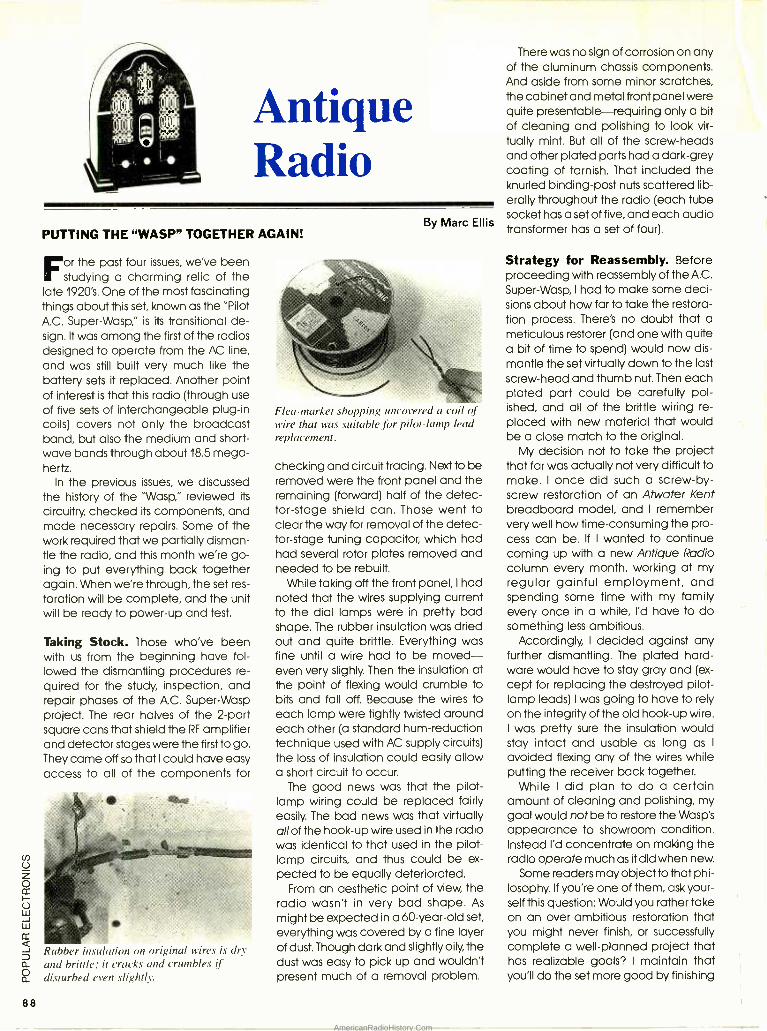
88
Antique Radio
PUTTING THE "WASP" TOGETHER AGAIN!
or the past four issues, we've been studying a charming relic of the
late 1920's. One of the most fascinating things about this set, known as the "Pilot A.C. Super-Wasp," is its transitional de- sign. It was among the first of the radios designed to operate from the AC line, and was still built very much like the battery sets it replaced. Another point of interest is that this radio (through use of five sets of interchangeable plug -in coils) covers not only the broadcast band, but also the medium and short- wave bands through about 18.5 mega- hertz.
In the previous issues, we discussed the history of the "Wasp," reviewed its
circuitry, checked its components, and made necessary repairs. Some of the work required that we partially disman- tle the radio, and this month we're go- ing to put everything back together again. When we're through, the set res-
toration will be complete, and the unit will be ready to power -up and test.
Taking Stock. Those who've been with us from the beginning have fol- lowed the dismantling procedures re- quired for the study, inspection, and repair phases of the A.C. Super -Wasp project. The rear halves of the 2 -part square cans that shield the RF amplifier and detector stages were the first to go. They came off so that I could have easy access to all of the components for
Rubber insulation on original wires is dry and brittle: it cracks and crumbles if disturbed even slightly.
By Marc Ellis
Flea -market shopping uncovered a coil of wire that was suitable for pilot -lamp lead replacement.
checking and circuit tracing. Next to be removed were the front panel and the remaining (forward) half of the detec- tor -stage shield can. Those went to clear the way for removal of the detec- tor- stage tuning capacitor, which had had several rotor plates removed and needed to be rebuilt.
While taking off the front panel, I had noted that the wires supplying current to the dial lamps were in pretty bad shape. The rubber insulation was dried out and quite brittle. Everything was fine until a wire had to be moved - even very slighly. Then the insulation at the point of flexing would crumble to bits and fall off. Because the wires to each lamp were tightly twisted around each other (a standard hum -reduction technique used with AC supply circuits) the loss of insulation could easily allow a short circuit to occur.
The good news was that the pilot - lamp wiring could be replaced fairly easily. The bad news was that virtually all of the hook -up wire used in the radio was identical to that used in the pilot - lamp circuits, and thus could be ex-
pected to be equally deteriorated. From an aesthetic point of view, the
radio wasn't in very bad shape. As
might be expected in a 60- year -old set,
everything was covered by a fine layer of dust. Though dark and slightly oily, the dust was easy to pick up and wouldn't present much of a removal problem.
There was no sign of corrosion on any of the aluminum chassis components. And aside from some minor scratches, the cabinet and metal front panel were quite presentable- requiring only a bit of cleaning and polishing to look vir- tually mint. But all of the screw -heads and other plated parts had a dark -grey coating of tarnish. That included the knurled binding -post nuts scattered lib- erally throughout the radio (each tube socket has a set of five, and each audio transformer has a set of four).
Strategy for Reassembly. Before proceeding with reassembly of the A.C.
Super -Wasp, I had to make some deci- sions about how far to take the restora- tion process. There's no doubt that a meticulous restorer (and one with quite a bit of time to spend) would now dis- mantle the set virtually down to the last screw -head and thumb nut. Then each plated part could be carefully pol- ished, and all of the brittle wiring re-
placed with new material that would be a close match to the original.
My decision not to take the project that far was actually not very difficult to make. I once did such a screw -by- screw restoration of an Atwater Kent breadboard model, and I remember very well how time -consuming the pro- cess can be. If I wanted to continue coming up with a new Antique Radio column every month, working at my regular gainful employment, and spending some time with my family every once in a while, I'd have to do something less ambitious.
Accordingly, I decided against any further dismantling. The plated hard- ware would have to stay gray and (ex-
cept for replacing the destroyed pilot - lamp leads) I was going to have to rely on the integrity of the old hook -up wire. I was pretty sure the insulation would stay intact and usable as long as I
avoided flexing any of the wires while putting the receiver back together.
While I did plan to do a certain amount of cleaning and polishing, my goal would not be to restore the Wasp's appearance to showroom condition. Instead I'd concentrate on making the radio operate much as it did when new.
Some readers may object to that phi- losophy. If you're one of them, ask your- self this question: Would you rather take on an over -ambitious restoration that you might never finish, or successfully complete a well -planned project that has realizable goals? I maintain that you'll do the set more good by finishing
AmericanRadioHistory.Com
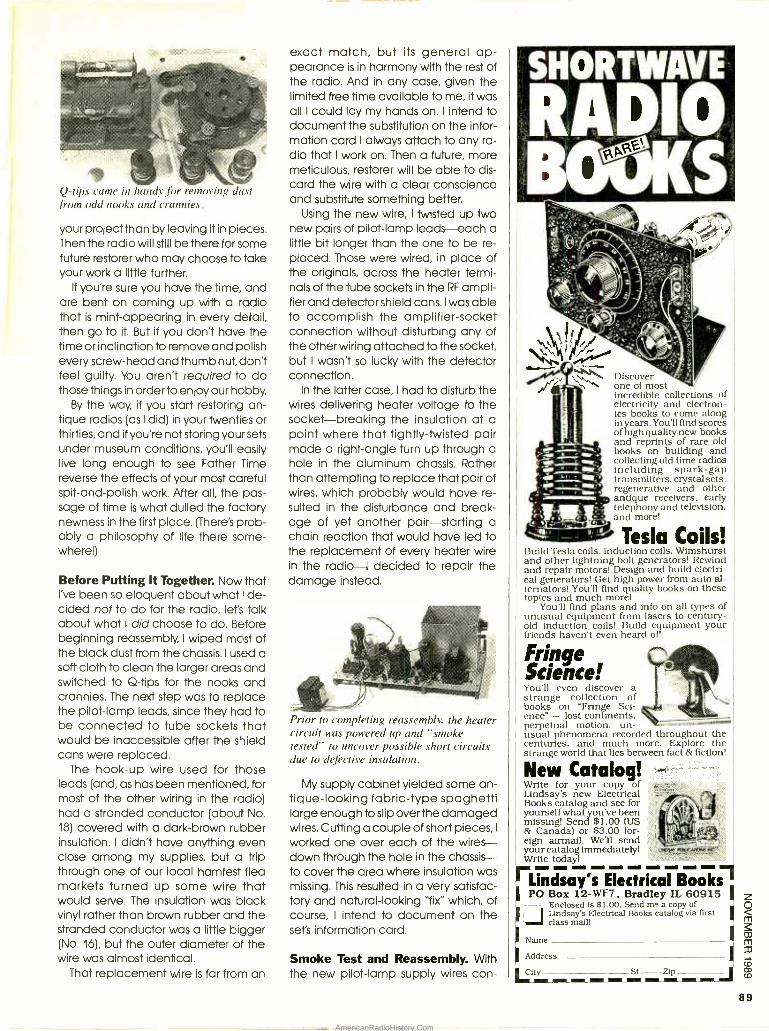
Q -tips came in handy for removing dust from odd nooks and crannies.
your project than by leaving it in pieces. Then the radio will still be there for some future restorer who may choose to take your work a little further.
If you're sure you have the time, and are bent on coming up with a radio that is mint -appearing in every detail, then go to it. But if you don't have the time or inclination to remove and polish every screw -head and thumb nut, don't feel guilty. You aren't required to do those things in order to enjoy our hobby.
By the way, if you start restoring an- tique radios (as I did) in your twenties or thirties, and if you're not storing your sets under museum conditions, you'll easily live long enough to see Father Time reverse the effects of your most careful spit- and -polish work. After all, the pas- sage of time is what dulled the factory newness in the first place. (There's prob- ably a philosophy of life there some- where!)
Before Putting It Together. Now that I've been so eloquent about what I de- cided not to do for the radio, let's talk about what I did choose to do. Before beginning reassembly, I wiped most of the black dust from the chassis. I used a soft cloth to clean the larger areas and switched to Q -tips for the nooks and crannies. The next step was to replace the pilot -lamp leads, since they had to be connected to tube sockets that would be inaccessible after the shield cans were replaced.
The hook -up wire used for those leads (and, as has been mentioned, for most of the other wiring in the radio) had a stranded conductor (about No. 18) covered with a dark -brown rubber insulation. I didn't have anything even close among my supplies, but a trip through one of our local hamfest flea markets turned up some wire that would serve. The insulation was black vinyl rather than brown rubber and the stranded conductor was a little bigger (No. 16), but the outer diameter of the wire was almost identical.
That replacement wire is far from an
exact match, but its general ap- pearance is in harmony with the rest of the radio. And in any case, given the limited free time available to me, it was all I could lay my hands on. I intend to document the substitution on the infor- mation card I always attach to any ra- dio that I work on. Then a future, more meticulous, restorer will be able to dis- card the wire with a clear conscience and substitute something better.
Using the new wire, I twisted up two new pairs of pilot -lamp leads-each a little bit longer than the one to be re- placed. Those were wired, in place of the originals, across the heater termi- nals of the tube sockets in the RF ampli- fier and detector shield cans. I was able to accomplish the amplifier- socket connection without disturbing any of the other wiring attached to the socket, but I wasn't so lucky with the detector connection.
In the latter case, I had to disturb the wires delivering heater voltage to the socket -breaking the insulation at a point where that tightly -twisted pair made a right -angle turn up through a hole in the aluminum chassis. Rather than attempting to replace that pair of wires, which probably would have re- sulted in the disturbance and break- age of yet another pair- starting a chain reaction that would have led to the replacement of every heater wire in the radio -I decided to repair the damage instead.
Prior to completing reassembly, the heater circuit was powered up and "smoke tested" to uncover possible short circuits due to defective insulation.
My supply cabinet yielded some an- tique- looking fabric -type spaghetti large enough to slip over the damaged wires. Cutting a couple of short pieces, I
worked one over each of the wires - down through the hole in the chassis - to cover the area where insulation was missing. This resulted in a very satisfac- tory and natural -looking "fix" which, of course, I intend to document on the sets information card.
Smoke Test and Reassembly. With the new pilot -lamp supply wires con-
Discover one of most incredible collections of electricity and electron- ics books to come along in years. You'll find scores of high quality new books and reprints of rare old books on building and collecting old time radios including spark -gap transmitters, crystal sets, regenerative and other antique receivers, early telephony and television, and more!
Tesla Coils! Build Tesla coils, induction coils, Wimshurst and other lightning bolt generators! Rewind and repair motors! Design and build electri- cal generators! Get high power from auto al- ternators! You'll find quality books on these topics and much morel
You'll find plans and info on all types of unusual equipment from lasers to century- old induction coils! Build equipment your friends haven't even heard ofl
Fringe Science! You'll even discover a strange collection of books on "Fringe Sci- ence" - lost continents, perpetual motion, un- usual phenomena recorded throughout the centuries, and much more. Explore the strange world that lies between fact & fiction!
New Catalog! Write for your copy al Lindsay's new Electrical Books catalog and see for yourself what you've been missing! Send $1.00 (US & Canada) or $3.00 for- eign airmail. We'll send your catalog immediately' Write today!
Lindsay's Electrical Books PO Boa 12- WF7 , Bradley IL 60915
Enclosed Is $1.00. Send me a copy of DLindsay's Electrical Books catalog via first class mail!
Name
Address ' Litt' St Zip
89
AmericanRadioHistory.Com
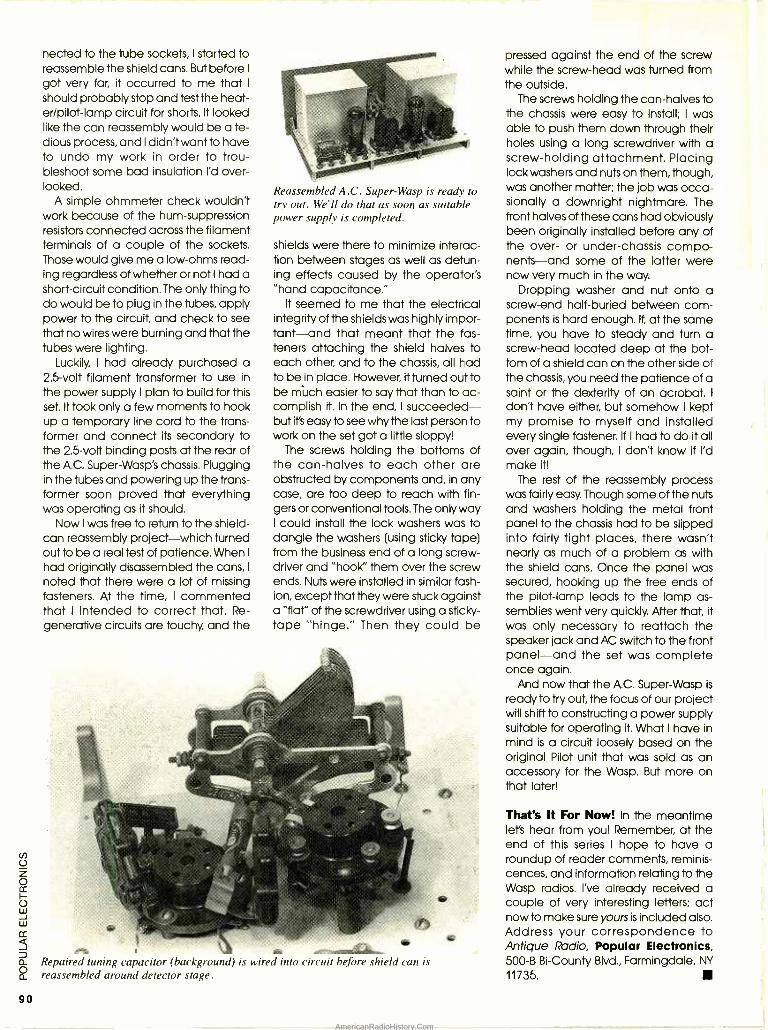
90
nected to the tube sockets, I started to reassemble the shield cans. But before I
got very far, it occurred to me that I
should probably stop and test the heat- er /pilot -lamp circuit for shorts. It looked like the can reassembly would be a te- dious process, and I didn't want to have to undo my work in order to trou- bleshoot some bad insulation I'd over- looked.
A simple ohmmeter check wouldn't work because of the hum -suppression resistors connected across the filament terminals of a couple of the sockets. Those would give me a low -ohms read- ing regardless of whether or not I had a short -circuit condition. The only thing to do would be to plug in the tubes, apply power to the circuit, and check to see that no wires were burning and that the tubes were lighting.
Luckily, I had already purchased a 2.5 -volt filament transformer to use in the power supply I plan to build for this set. It took only a few moments to hook up a temporary line cord to the trans- former and connect its secondary to the 2.5 -volt binding posts at the rear of the A.C. Super -Wasp's chassis. Plugging in the tubes and powering up the trans- former soon proved that everything was operating as it should.
Now I was free to return to the shield - can reassembly project-which turned out to be a real test of patience. When I
had originally disassembled the cans, I
noted that there were a lot of missing fasteners. At the time, I commented that I intended to correct that. Re- generative circuits are touchy, and the
Reassembled A.C. Super -Wasp is ready to try out. We'll do that as soon as suitable power supply is completed.
shields were there to minimize interac- tion between stages as well as detun- ing effects caused by the operator's "hand capacitance."
It seemed to me that the electrical integrity of the shields was highly impor- tant -and that meant that the fas- teners attaching the shield halves to each other, and to the chassis, all had to be in place. However, it turned out to be múch easier to say that than to ac- complish it. In the end, I succeeded - but it's easy to see why the last person to work on the set got a little sloppy!
The screws holding the bottoms of the can -halves to each other are obstructed by components and, in any case, are too deep to reach with fin- gers or conventional tools. The only way I could install the lock washers was to dangle the washers (using sticky tape) from the business end of a long screw- driver and "hook" them over the screw ends. Nuts were installed in similar fash- ion, except that they were stuck against a "flat" of the screwdriver using a sticky - tape "hinge." Then they could be
Repaired tuning capacitor (background) is wired into circuit before shield can is reassembled around detector stage.
pressed against the end of the screw while the screw -head was turned from the outside.
The screws holding the can -halves to the chassis were easy to install; I was able to push them down through their holes using a long screwdriver with a screw -holding attachment. Placing lock washers and nuts on them, though, was another matter; the job was occa- sionally a downright nightmare. The front halves of these cans had obviously been originally installed before any of the over- or under- chassis compo- nents -and some of the latter were now very much in the way.
Dropping washer and nut onto a screw -end half -buried between com- ponents is hard enough. If, at the same time, you have to steady and turn a screw -head located deep at the bot- tom of a shield can on the other side of the chassis, you need the patience of a saint or the dexterity of an acrobat. I
don't have either, but somehow I kept my promise to myself and installed every single fastener. If I had to do it all over again, though, I don't know if I'd make it!
The rest of the reassembly process was fairly easy. Though some of the nuts and washers holding the metal front panel to the chassis had to be slipped into fairly tight places, there wasn't nearly as much of a problem as with the shield cans. Once the panel was secured, hooking up the free ends of the pilot -lamp leads to the lamp as- semblies went very quickly. After that, it was only necessary to reattach the speaker jack and AC switch to the front panel -and the set was complete once again.
And now that the A.C. Super -Wasp is
ready to try out, the focus of our project will shift to constructing a power supply suitable for operating it. What I have in mind is a circuit loosely based on the original Pilot unit that was sold as an accessory for the Wasp. But more on that later!
That's It For Now! In the meantime let's hear from you! Remember, at the end of this series I hope to have a roundup of reader comments, reminis- cences, and information relating to the Wasp radios. I've already received a couple of very interesting letters; act now to make sure yours is included also. Address your correspondence to Antique Radio, Popular Electronics, 500 -B Bi- County Blvd., Farmingdale, NY
11735.
AmericanRadioHistory.Com
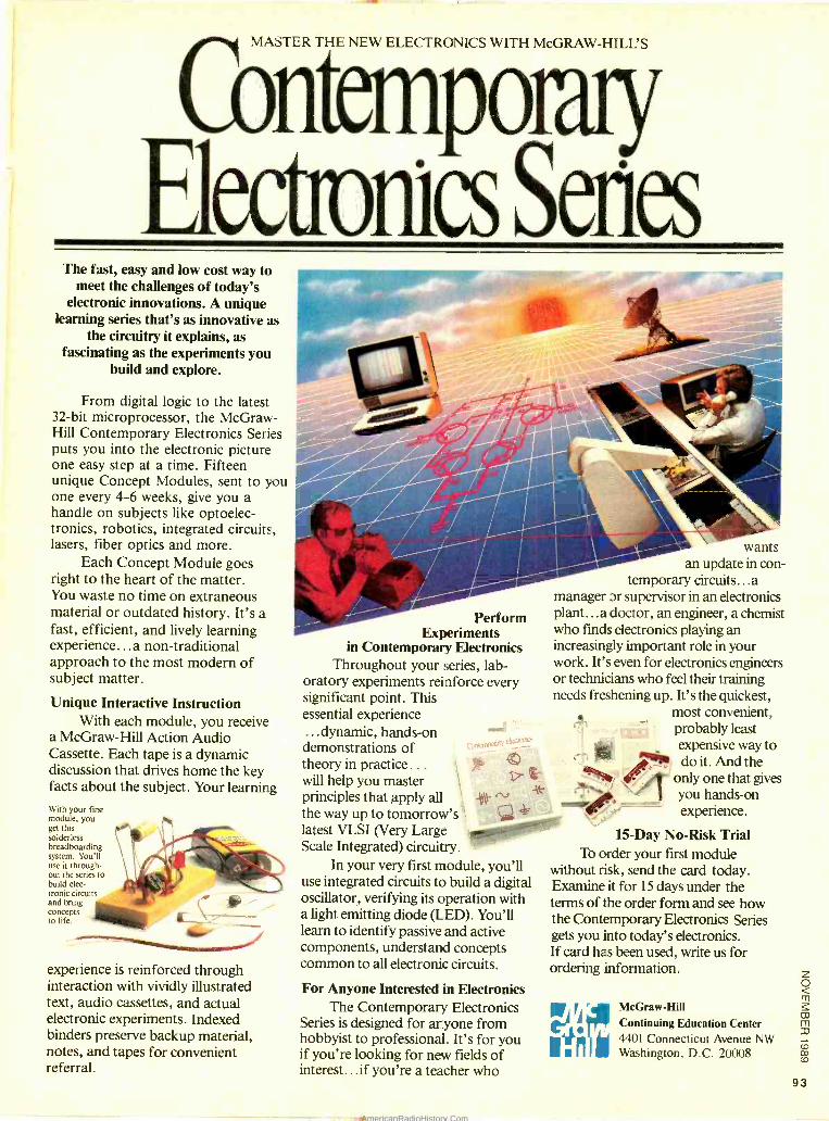
MASTER THE NEW ELECTRONICS WITH McGRAW -HILL'S
n poraiy &awes Series
The fast, easy and low cost way to meet the challenges of today's
electronic innovations. A unique learning series that's as innovative as
the circuitry it explains, as fascinating as the experiments you
build and explore.
From digital logic to the latest 32 -bit microprocessor, the McGraw - Hill Contemporary Electronics Series puts you into the electronic picture one easy step at a time. Fifteen unique Concept Modules, sent to yol one every 4 -6 weeks, give you a handle on subjects like optoelec- tronics, robotics, integrated circuits, lasers, fiber optics and more.
Each Concept Module goes right to the heart of the matter. You waste no time on extraneous material or outdated history. It's a fast, efficient, and lively learning experience ... a non -traditional approach to the most modern of subject matter.
Unique Interactive Instruction With each module, you receive
a McGraw -Hill Action Audio Cassette. Each tape is a dynamic discussion that drives home the key facts about the subject. Your learning With your first module, you get this solderless breadboarding system. You'll use it through- out the series to build elec- tronic circuits
concepts to life.
and bring
460-
experience is reinforced through interaction with vividly illustrated text, audio cassettes, and actual electronic experiments. Indexed binders preserve backup material, notes, and tapes for convenient referral.
Perform Experiments
in Contemporary Electronics Throughout your series, lab-
oratory experiments reinforce every significant point. This essential experience ...dynamic, hands -on demonstrations of theory in practice.. .
will help you master principles that apply all the way up to tomorrow's latest VLSI (Very Large Scale Integrated) circuitry.
In your very first module, you'll use integrated circuits to build a digital oscillator, verifying its operation with a light emitting diode (LED). You'll learn to identify passive and active components, understand concepts common to all electronic circuits.
For Anyone Interested in Electronics The Contemporary Electronics
Series is designed for anyone from hobbyist to professional. It's for you if you're looking for new fields of interest...if you're a teacher who
MOM
wants
111011.1.111111111 an update in con-
temporary circuits...a manager or supervisor in an electronics plant... a doctor, an engineer, a chemist who finds electronics playing an increasingly important role in your work. It's even for electronics engineers or technicians who feel their training needs freshening up. It's the quickest,
most convenient, probably least expensive way to I"! do it. And the
/ ` ' 1
only one that gives you hands -on experience.
15 -Day No -Risk Trial To order your first module
without risk, send the card today. Examine it for 15 days under the terms of the order form and see how the Contemporary Electronics Series gets you into today's electronics. If card has been used, write us for ordering information.
F/ , McGraw -Hill
Continuing Education Center I I 4401 Connecticut Avenue NW I I Washington, D.C. 20008
93
AmericanRadioHistory.Com
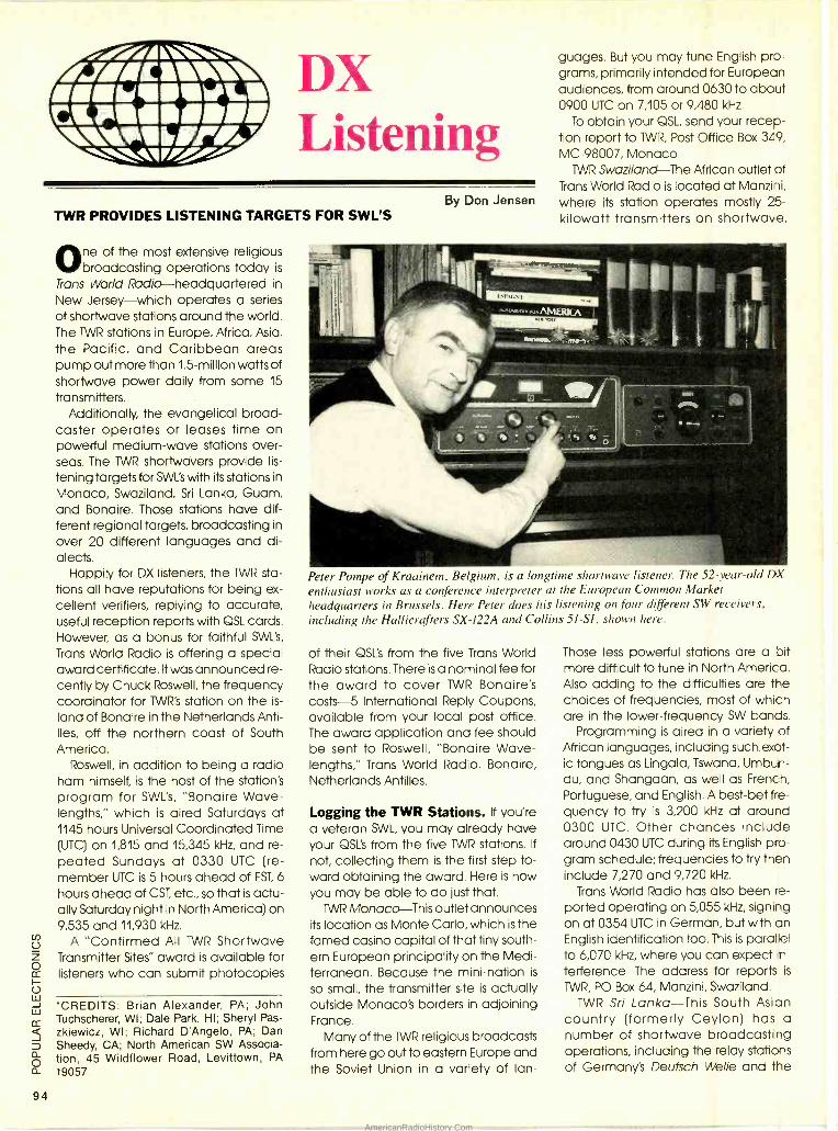
..1461101011 MAIM//1 \VW lb/P/' 1 // DX Listening
94
TWR PROVIDES LISTENING TARGETS FOR SWL'S
One of the most extensive religious broadcasting operations today is
Trans World Radio- headquartered in
New Jersey -which operates a series of shortwave stations around the world. The TWR stations in Europe, Africa, Asia, the Pacific, and Caribbean areas pump out more than 1.5- million watts of shortwave power daily from some 15
transmitters. Additionally, the evangelical broad-
caster operates or leases time on powerful medium -wave stations over- seas. The TWR shoriwavers provide lis-
tening targets for SWL's with its stations in
Monaco, Swaziland, Sri Lanka, Guam, and Bonaire. Those stations have dif- ferent regional targets, broadcasting in
over 20 different languages and di- alects.
Happily for DX listeners, the 1WR sta- tions all have reputations for being ex-
cellent verifiers, replying to accurate, useful reception reports with QSL cards. However, as a bonus for faithful SWL's,
Trans World Radio is offering a special award certificate. It was announced re- cently by Chuck Roswell, the frequency coordinator for TWR's station on the is-
land of Bonaire in the Netherlands Anti- lles, off the northern coast of South America.
Roswell, in addition to being a radio ham himself, is the host of the station's program for SWL's, "Bonaire Wave- lengths," which is aired Saturdays at 1145 hours Universal Coordinated Time (UTC) on 1,815 and 15,345 kHz, and re- peated Sundays at 0330 UTC (re- member UTC is 5 hours ahead of EST, 6 hours ahead of CST, etc., so that is actu- ally Saturday night in North America) on 9,535 and 11,930 kHz.
A "Confirmed All TWR Shortwave Transmitter Sites" award is available for listeners who can submit photocopies
*CREDITS: Brian Alexander, PA; John Tuchscherer, WI; Dale Park, HI; Sheryl Pas - zkiewicz, WI; Richard D'Angelo, PA; Dan Sheedy, CA; North American SW Associa- tion, 45 Wildflower Road, Levittown, PA 19057.
By Don Jensen
guages. But you may tune English pro- grams, primarily intended for European audiences, from around 0630 to about 0900 UTC on 7,105 or 9,480 kHz.
To obtain your QSL, send your recep- tion report to 1WR, Post Office Box 349, MC- 98007, Monaco.
TWR Swaziland -The African outlet of Trans World Radio is located at Manzhi, where its station operates mostly 25- kilowatt transmitters on shortwave.
Peter Pompe of Kraainem. Belgium, is a longtime shortwave listener. The 52 -year -old DX
enthusiast works as a conference interpreter at the European Common Market headquarters in Brussels. Here Peter does his listening on four different SW receivers, including the Hallicrafters SX -122A and Collins 51 -Sl, shown here.
of their QSL's from the five Trans World Radio stations. There is a nominal fee for the award to cover TWR Bonaire's costs 5 International Reply Coupons, available from your local post office. The award application and fee should be sent to Roswell, "Bonaire Wave- lengths," Trans World Radio, Bonaire, Netherlands Antilles.
Logging the TWR Stations. If you're a veteran SWL, you may already have your QSL's from the five TWR stations. If
not, collecting them is the first step to- ward obtaining the award. Here is how you may be able to do just that.
TWR Monaco -This outlet announces its location as Monte Carlo, which is the famed casino capital of that tiny south- em European principality on the Medi- terranean. Because the mini -nation is
so small, the transmitter site is actually outside Monaco's borders in adjoining France.
Many of the TWR religious broadcasts from here go out to eastern Europe and the Soviet Union in a variety of Ian-
Those less powerful stations are a pit more difficult to tune in North America. Also adding to the difficulties are the choices of frequencies, most of which are in the lower- frequency SW bands.
Programming is aired in a variety of African languages, including such exot- ic tongues as Lingala, Tswana, Umbun- du, and Shangaan, as well as French, Portuguese, and English. A best -bet fre- quency to try is 3,200 kHz at around 0300 UTC. Other chances include around 0430 UTC during its English pro- gram schedule; frequencies to try then include 7,270 and 9,720 kHz.
Trans World Radio has also been re- ported operating on 5,055 kHz, signing on at 0354 UTC in German, but with an English identification too. This is parallel to 6,070 kHz, where you can expect in-
terference. The address for reports is
TWR, PO Box 64, Manzini, Swaziland. TWR Sri Lanka -This South Asian
country (formerly Ceylon) has a number of shortwave broadcasting operations, including the relay stations of Germany's Deutsch Welle and the
AmericanRadioHistory.Com
Voice of America, plus the national Sri Lanka Broadcasting Corp. transmitters.
TWR leases shortwave broadcasting time from the latter, although it owns its
own powerful medium -wave transmit- ter on that island nation. The station has been noted on 11,830 kHz at its 1200 UTC sign on, and at other times and frequencies. Reports may be sent to TWR, PO Box 364, Columbo, Sri Lanka.
TWR Guam -This station announces as Trans World Radio Pacific and, since it is in U.S. Territory, it carries the call letters of KTWR. The station (located in Agana, Guam) operates four 100 -kW, SW trans- mitters that at times can be heard rather well in our part of the world.
Like Bonaire's outlet, this TWR broad- caster also has a program especially for shortwave listeners. It is called "Pacif- ic DX Magazine," and is broadcast Sat- urdays at 0380 UTC on 11,830 kHz. Or tune in for English programming on 11,650 kHz at around 1530 UTC. Another frequency for the Trans World Radio Pa- cific station is 11,650, which can be heard in English with religious talk and hymns from just before 1600 UTC. The address for your reports and QSL re- quests is TWR Pacific, KTWR, Box CC, Agana, Guam, 96910,
TWR Bonaire -This outlet is, without doubt, the easiest of the Trans World Radio outlets to hear. English program- ming is broadcast from 0300 to 0540 UTC on 9,535 kHz, and again during the 0115 -1300 UTC period on 11,815 and 15,345 kHz. The address is Trans World Radio, Bonaire, Netherlands Antilles.
As with most shortwave stations, the frequencies, and sometimes the broadcasting hours as well, do change with the seasons. So if you have some difficulty in finding those stations, tune around a bit and you may find them on other frequencies or bands. Also, those are stations financed by religious sup- porters, hence they do appreciate re- turn postage -in the form of Interna- tional Reply Coupons -if you would like an airmail reply to your reports and QSL requests.
Good luck in your quest for the TWR award!
Feedback. Keep those letters coming. Your comments, questions, and logging tips are always most welcome. I'll in- clude as many of them as I can in the feedback section of this column. Ad- dress your correspondence to DX Lis- tening, Popular Elèctronics, 500 -B Bi-
County Blvd., Farmingdale, NY 11735. Bill Smith, Weatland, WY writes with
the sort of message that warms the heart -and, I hope, catches the atten- tive eye of my editor. "Great column!" says Bill. "Keep it up. With columns like yours in it, I'm hooked on Popular Elec- tronics.
Thanks, Bill!
Next out of the mailbag is a question directed to me and also to you, the readers of DX Listening.
Art Ervin, Richmond, VA, has this que- ry? "Which shortwave station has the best QSL card? I have my own opinion, based on those I've received," notes Art. "I know it's an opinion question, but I
wonder what you think Don? And I'd also like to hear what other readers think about this."
That is a bit of a toughie, Art. Going back a goodly number of years, a long - silent shortwave outlet in the Canary Islands had a gorgeous embossed red, gold, and black card featuring a map grid of the Atlantic Ocean, with the Spanish -owned island chain promi- nently located. That surely must be one of my favorites.
Today there probably are a number of legitimate claimants to the title, Radio Japan and HCJB in Quito, Ec- uador, being just a couple of candi- dates that come quickly to mind.
Turning to the last part of Art's query, what do readers think is the best looking QSL card? Why? Send me your ideas on this question and we'll go over them in a future column.
Down the Dial. Here are some of the loggings that your fellow readers have been reporting recently.
Brazil -4,845 kHz. From the heart of the Amazon comes the Portuguese lan- guage programming of Radio Na- cional Manaus. This station has been reported in the eastern U.S. during the evening hours until sign off, just after 0400 UTC.
Iceland- 15,770 kHz. The Iceland Station Broadcasting Service at Reyk- javik has news in Icelandic, with a bit of English too, noted at 1410 UTC, which is
also transmitted on 17,530 kHz at the same time.
Mexico -9,555 kHz. La Hora Exacts, "the exact time station," in Mexico City, has time signals each minute, sur- rounded by Spanish -language com- mercials, announcements, and jingles.
Qatar -7,320 kHz. The shortwave outlet at Doah, capital of this Mid -East nation, can be heard until sign off at about 2130 UTC with Arabic music and Islamic religious programming.
BUILD -IT BOOKS FOR EXPERIMENTERS
Modern Op Amp BP106- MODERN OP- AMP PROJECTS .... $5.75. Wide range of build - it projects that use op- amps. Easy to build board layouts provided for most. A variety of projects of all kinds are included.
Projects
#223- PROJECTS USING T-IE CA3130 .... $5.00. 50 different ways to put this op -amp to work in- cluding audio, RF, test equipment, household and miscellaneous projects.
rro.°°`c.arao
BP44 -IC 555 PROJ- ECTS .... $5.95. Included are basic and general timer circuits, automobile and model railroad circuits, alarms and noise makers, as well as a section on 556, 558, and 559 timers.
n #224 -50 CMOS IC O. PROJECTS .... $5.25. These IC's are suitable for an extraordinary range of applications. This book shows you just how much you can do with them.
n BP59 -2ND BOOK OF CMOS IC PROJECTS ... .
$5.50. Still more ways to use these versatile devices. None of these projects over- lap those in book #224. The pair make a wonderful circuit reference set.
BP84- DIGITAL IC PROJECTS .... $5.50. Both simple and more ad- vanced projects to help the reader develop a knowl- edge of the workings of digi- tal circuits. A number of board layouts are included.
MOW
MAIL TO: Electronic Technology Today Inc. P.O. Box 240 Massapequa Park, NY 11762 -0240
SHIPPING CHARGES IN USA AND CANADA
$0.01 to $5.00 ... $1.25 $30.01 to $40.00 $5.00 $5.01 to 10.00 ... $2.00 $40.01 to $50.00 $6.00 $10.01 to $20.00 $3.00 $50.01 and above $7.50 $20.01 to $30.00 $4.00 SORRY, No orders accepted outside of USA and Canada
Total price of merchandise $ Shipping (see chart) $
Subtotal $
Sales Tax (NYS only) $
Total Enclosed $
Name
Address
City State Zip
I-
AmericanRadioHistory.Com
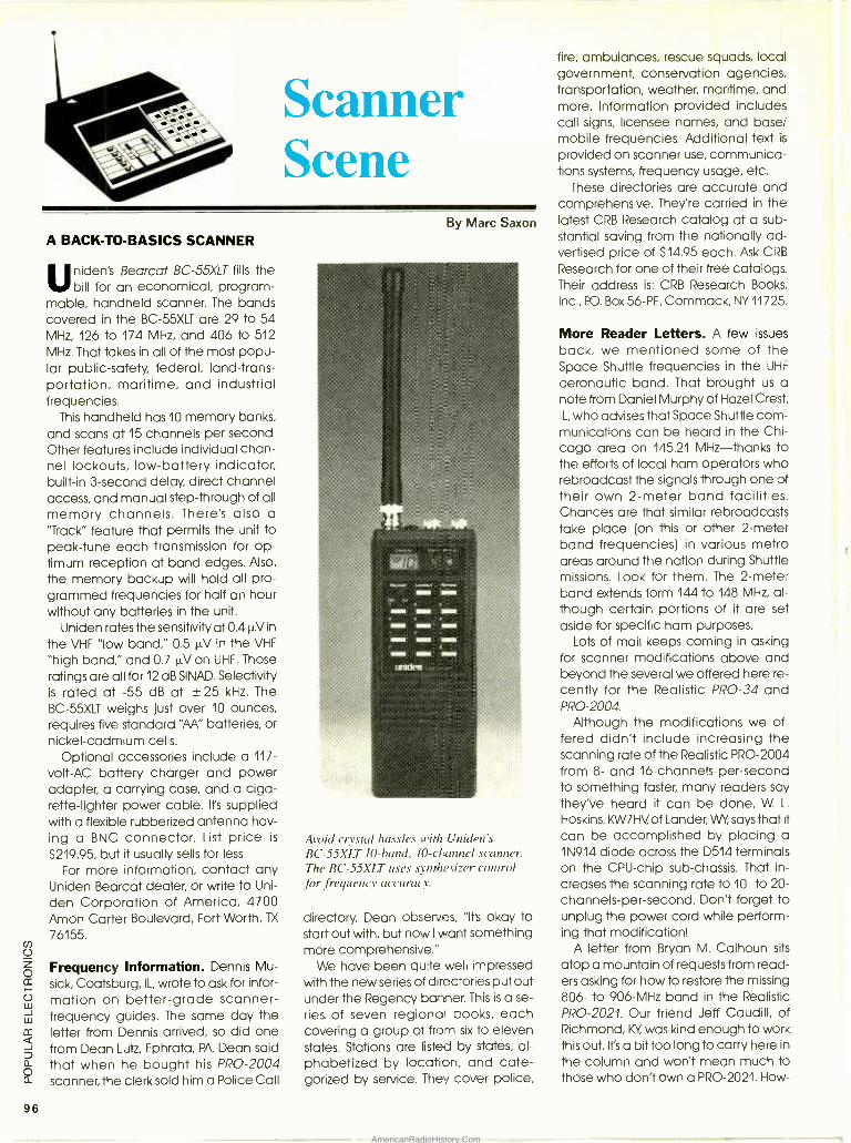
96
Scanner Scene
A BACK -TO- BASICS SCANNER
linden's Bearcat BC -55XLT fills the bill for an economical, program-
mable, handheld scanner. The bands covered in the BC -55XLT are 29 to 54 MHz, 126 to 174 MHz, and 406 to 512
MHz. That takes in all of the most popu- lar public- safety, federal, land- trans- portation, maritime, and industrial frequencies.
This handheld has 10 memory banks, and scans at 15 channels per second. Other features include individual chan- nel lockouts, low- battery indicator, built -in 3- second delay, direct channel access, and manual step- through of all memory channels. There's also a "Track" feature that permits the unit to peak -tune each transmission for op- timum reception at band edges. Also,
the memory backup will hold all pro- grammed frequencies for half an hour without any batteries in the unit.
Uniden rates the sensitivity at 0.4 µV in
the VHF "low band," 0.5 µV in the VHF
"high band," and 0.7 µV on UHF. Those ratings are all for 12 dB SINAD. Selectivity is rated at -55 dB at ± 25 kHz. The BC -55XLT weighs just over 10 ounces, requires five standard "M" batteries, or nickel- cadmium cells.
Optional accessories include a 117 -
volt-AC battery charger and power adapter, a carrying case, and a ciga- rette- lighter power cable. It's supplied with a flexible rubberized antenna hav- ing a BNC connector. List price is
$219.95, but it usually sells for less.
For more information, contact any Uniden Bearcat dealer, or write to Uni-
den Corporation of America, 4700 Amon Carter Boulevard, Fort Worth, TX
76155.
Frequency Information. Dennis Mu-
sick, Coatsburg, IL, wrote to ask for infor- mation on better -grade scanner - frequency guides. The same day the letter from Dennis arrived, so did one from Dean Lutz, Ephrata, PA. Dean said that when he bought his PRO -2004 scanner, the clerk sold him a Police Call
By Marc Saxon
Avoid crystal hassles with [Mitten's BC -55XLT 10 -band, 10- channel scanner. The BC -55X11 uses synthesizer control for frequency accuracy.
directory. Dean observes, "Ifs okay to start out with, but now I want something more comprehensive."
We have been quite well impressed with the new series of directories put out under the Regency banner. This is a se-
ries of seven regional books, each covering a group of from six to eleven states. Stations are listed by states, al- phabetized by location, and cate- gorized by service. They cover police,
fire, ambulances, rescue squads, local government, conservation agencies, transportation, weather, maritime, and more. Information provided includes call signs, licensee names, and base/ mobile frequencies. Additional text is
provided on scanner use, communica- tions systems, frequency usage, etc.
These directories are accurate and comprehensive. They're carried in the latest CRB Research catalog at a sub- stantial saving from the nationally ad- vertised price of $14.95 each. Ask CRB
Research for one of their free catalogs. Their address is: CRB Research Books,
Inc., PO. Box 56 -PE, Commack, NY 11725.
More Reader Letters. A few issues
back, we mentioned some of the Space Shuttle frequencies in the UHF
aeronautic band. That brought us a note from Daniel Murphy of Hazel Crest, IL, who advises that Space Shuttle com- munications can be heard in the Chi- cago area on 145.21 MHz -thanks to the efforts of local ham operators who rebroadcast the signals through one of their own 2 -meter band facilities. Chances are that similar rebroadcasts take place (on this or other 2 -meter band frequencies) in various metro areas around the nation during Shuttle missions. Look for them. The 2 -meter band extends form 144 to 148 MHz, al- though certain portions of it are set aside for specific ham purposes.
Lots of mail keeps coming in asking for scanner modifications above and beyond the several we offered here re- cently for the Realistic PRO -34 and PRO -2004.
Although the modifications we of- fered didn't include increasing the scanning rate of the Realistic PRO -2004 from 8- and 16- channels -per -second to something faster, many readers say they've heard it can be done. W. L.
Hoskins, KW7HVof Lander, WY, says that it can be accomplished by placing a 1N914 diode across the D514 terminals on the CPU -chip sub -chassis. That in- creases the scanning rate to 10- to 20- channels -per- second. Don't forget to unplug the power cord while perform- ing that modification!
A letter from Bryan M. Calhoun sits
atop a mountain of requests from read- ers asking for how to restore the missing 806- to 906 -MHz band in the Realistic PRO -2021. Our friend Jeff Caudill, of Richmond, KY was kind enough to work this out. It's a bit too long to carry here in
the column and won't mean much to those who don't own a PRO -2021. How-
AmericanRadioHistory.Com
ever, if you want that information, I'll be happy to send it if you send me a stamped self -addressed envelope. Use the address at the end of this column.
Manny Lopez, Jamaica, NY, says that he's interested in monitoring FAA ground and operational communica- tions that take place at larger airports, since he's within monitoring range of Iwo major airports.
Monitors, nationally, might wish to tune in on the operations of the FAA,
which are often interesting as they han- dle the behind- the -scenes logistics of air safety and navigation. I have found that 166.175 MHz is pretty active at many FM facilities. Also note that the agency has frequencies between 172.125 and 172.175 MHz, and 172.825 and 172.975 MHz (25 -kHz spacing) that you might wish to check. As previously mentioned here, monitor 135.85 and 135.95 MHz for FM "Flight Check" air- craft communicating with ground facil- ities while checking on the operations of airport radio -navigation facilities. There are some additional frequencies used nationally, but those mentioned here are the most popularly encoun- tered in all areas.
Ed Voscovik, of Alberta says that fre- quencies 36.25 and 40.01 MHz have produced activity during "skip" open- ings. Those have related to cleaning up the big oil spill in Alaskan waters. Ed passes along the information so that we can share it with all of our readers. Thanks Ed!
If you have loggings or frequencies to share, or questions, or photos of your station, or if you've got a scanner -re- lated newspaper clipping, we are wait- ing to hear from you, Write to us at: Scanner Scene, Popular Electronics, 500 -B Bi- County Boulevard, Farm- ingdale, NY 11735. Let's hear from you soon!
"I'm not sure what it does - but I had to have it!'
VOICE OPERATED SWITCH (Continued from page 78)
With a signal of proper polarity ap- plied to U5, TR1 will be activated, switch- ing AC power to the lamp. If the application of the proper signal doesn't trigger TR1 into conduction, dis- connect AC power and troubleshoot the wiring. Check the 5 -volt source with a voltmeter; if its okay, remove power, install U4, and finish assembly.
Using the Project. The lamp should flash once, indicating a system power - up reset and that the circuit is awaiting your verbal command of "turn light on" to activate the lamp. Follow with the command "turn light off" to extinguish the light. The author found that the cir- cuit also responds to "go light go" fol- lowed by "go light gone" for lamp control.
The Voice -Operated Switch preforms best if you limit the audio gain of the amplifier by adjusting R5 to no more than needed to avoid false triggering from random noise. The use of a direc- tional microphone can also help. Plac- ing a length of cardboard tubing over the condenser microphone can help make it directional.
The circuit is particularly useful for controlling a light where the switch is in a poor location or for the mobility im- paired person in your household. You can't help feeling a sense of power when walking into a dark room, asking for the light, and having it obey your command. Certainly, it should impress your friends.
SOMEONE YOU
KNOW HAS A RARE DISORDER
That may be fatal or disabling That many doctors don't recognize That may have no cure or treatment That is one of 5000 disorders with a total of 20 million victims
NORD is a coalition of non -profit agencies, re- searchers, and individuals that helps by pro- viding information and promoting research. Your membership helps.
NORD National Organization for Rare Disorders 1182 Broadway, Suite 402. New York, N.Y. 10001 212-686 -1057
A New AOR Scanner
100 Channels Low, Air, High, UHF & 800MHz
Perfect for base or mobile. Includes AC and DC power cords, mobile mount hardware $299.00 and 2 antennas. Covers 27- 54MHz, 108- 174MHz, 406- 512MHz and 830- 950MHz. 5 Scan Banks and 5 Search Banks 25 Day Satisfaction Guarantee No Frequencies Cut Out. Size: 3117"H x 52/5"W x 7743 'D. Wt.: 21b. 10 oz.
COMMUNICATIONS 10707 E. 106th St. Indpla., IN 46256
Toll Free 800 -445 -7717 Visa and MasterCard Nom+ t! (COD slightly higher) Lam_
In Indiana 317 -849 -2570 Collect FAX (317) 849 -8794
Total Price, Freight Prepaid (Express Shipping Optwna:
CIRCLE 16 ON FREE INFORMATION CARD
Be an FCC LICENSED ELECTRONIC TECHNICIAN!
_A-l I h - No costly School. No commuting to class. The Original Home -Study course pre- pares you for the "FCC Commercial Radio- telephone License". This valuable license is your "ticket" to thousands of exciting jobs in Communications, RadioTV, Micro- wave, Computers, Radar, Avionics and more! You don't need a college degree to qualify, but you do need an FCC License. No Need to Quit Your Job or Go To School This proven course is easy, fast and low cost! GUARANTEED PASS - You get your FCC License or money refunded. Send for FREE facts now. MAIL COUPON TODAY!
cómmáñD PRODUCTIOMS FCC LICENSE TRAINING, Dept. 203 - P.O. Box 2824, San Francisco, CA 94126
Please rush FREE details immediately! NAME
ADDRESS_
t CITY _ STATE ZIP
olio II
MOM o t °O O tr OI .
Learn it home in span time. No previous experience needed!
97 AmericanRadioHistory.Com
98
SUPPLYING THE WORKSHOP (Continued from page 72)
stuff, the first prize must certainly go to JerryCo, Inc. The selection of scientific, industrial, and military surplus offered by that company is simply amazing, and the prices are generally quite low.
The best way to convey some idea of the JerryCo inventory is to dip into it.
One recent catalog features the follow- ing: a spark coil, tube tester, laser unit, air compressor, robot motor, magnets, lenses, prisms, fiber optics, project boxes, pharmaceutical bottles, steel balls, carbide drills, heat sinks, quartz tubing, rubber tubing, vinyl tubing, filter paper, and a huge 5 -volt, 115 -amp transformer.
For those of you interested in expand- ing the range of your experimental work and construction activities, Jer- ryCo is an excellent place to begin. The
catalog, which comes out about six
times a year, is $0.50. Each year, the U.S. Government dis-
cards tons of serviceable but un- needed or unwanted goods. Where does it all wind up? Well, if it is elec- tronics oriented, a good deal of it winds up in the hands of Fair Radio Sales. Their catalog, which is free, is chock full of interesting components, subassem- blies, complete units, and wonderful oddities.
The serious amateur scientist will oc- casionally require materials, like chemi- cals, available only from a laboratory supply house. This does not necessarily mean buying 5 pounds of something when you only need a few ounces. Chemicals in small quantities, as well as
professional laboratory equipment, can be ordered from a couple of excel- lent companies, one in the Midwest, the other on the west coast. These are: Hagenow Laboratories and Chem - Lab. The Hagenow catalog is $1.00.
Chem -Lab puts out two catalogs, a chemical listing for $3.00 and an equipment listing for $4.00 (or both for $5.00).
Those who enjoy servicing video or audio equipment will want to obtain a catalog from Consolidated Electronics. There you will find such items as video and audio tape head, motors, flyback transformers, speakers, turntable belts, semiconductors, and even vacuum tubes! Their catalog costs $3.00 and there is a $10 minimum order.
Antique Parts. Perhaps the most diffi- cult area to discuss is that of antique
parts and materials. Some of those things can be very hard to locate. But
even that is not always true. Needs vary enormously and where you happen to live can make a big difference. In cer- tain urban areas, the large number of flea markets and antique stores can make looking for old components a pleasure. In certain newly developed suburban regions, the antique -radio enthusiast may just go hungry.
The most general recommendation I
can make is this; Keep your eyes peeled and never overlook anything.
A couple of years ago I spotted a very large old vacuum tube in the win- dow of a resale store near my home in
Chicago. So I walked in and asked how much. It was $3.00. Sold! Then, I looked around. Half the store was covered - and I mean covered -with electronic parts, some of them going back to the 1940's and 1950's. It was really a lot of stuff. I thought of buying it all. I figured it would cost too much money. Oh well.
But lust is lust, and as I headed for the door, I inquired, just for the heck of it:
"What do you want for the whole bunch ?" I couldn't believe my ears. They wanted $50.00 for what amounted to ten cardboard cartons and one shabby suitcase full of switch- es, coils, controls, tubes, knobs, and hardware -just about everything you could imagine.
As I packed my car, I became curi- ous. I wanted to know where it all came from. I was told that it was the entire contents of someone's basement work- shop.
"Doesn't the man want it anymore ?" I
asked. "hope" "How come ?" "He's dead." Someday, something like that may
happen again. But I think I'm in for a long wait. In the meantime, I keep a catalog from Antique Electronic Supply handy. This company stocks a wide vari- ety of pre- transistor components guar- anteed to make the antique -radio fan very happy. The selection includes high -voltage capacitors, power trans- formers, old style binding posts, tubes, tube sockets, speakers, grill cloths, and (believe it or not) cloth covered hook- up wire. The catalog is $2.00.
Parts for old radios, crystal sets es-
pecially, are also available from Yeary Communications. For a free catalog, send them one large SASE.
A Last Resort. When all else fails, or
sometimes when I'm simply too lazy to do the necessary consumer research,. I
generally turn to Newark Electronics, a very large organization with branch ot- fices all over the country. The Newark inventory is utterly tremendous. Even their catalog, which is nearly 2 inches thick, is tremendous. If you really, really need something (other than antique parts, of course), and if you're on the edge of giving up, look to Newark Elec- tronics. The chances are good that Newark will have what you want, or something close to it.
Several months ago, I needed some large 1.5 -volt dry cells. Newark had them. Then I needed a spool of heavy - gauge magnet wire. Newark had it.
Then I needed a large, deep, cube - shaped project box. Of course, Newark had that too.
I find it comforting to know that I can get this kind of stuff when I need it. Bu -,
Newark is definitely not cheap. Anc, since the minimum sale is $25.00, you may be forced to order things that you do not actually require at the moment. The Newark catalog, which also makes a pretty good technical reference manual, is free. Check the phone boo <
for the branch office nearest you.
Everything is Somewhere. I should like to end on an optimistic note. My experience is that no matter how strange, unusual, or downright bizarre your needs become, the thing you want exists somewhere. The companies I've mentioned here are the ones that have come through regularly for me. But they are by no means the only ones that carry items of interest for the elec- tronics enthusiast. Just keep looking, and don't forget the junkbox.
GET OUT OF THE DARK.
Open your eyes and see just how many subjects are covered in the new edition of the Consumer Information Catalog. It's free just for the asking and so are nearly half of the 200 federal publications described inside. Book- lets on subjects like financial and career planning; eating right, exercis- ing, and staying healthy; housing and child care; federal benefit programs. Just about everything you would need to know. Write today. We'll send you the latest edition of the Consumer Informa- tion Catalog, which is updated and published quarterly. It'll be a great help, you'll see. Just write:
Consumer Information Center Dept. TD, Pueblo, Colorado 81009
AmericanRadioHistory.Com
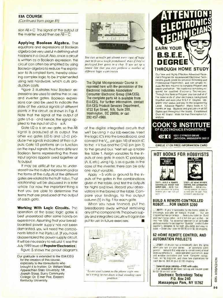
EIA COURSE (Continued from page 81)
sion AB + C. The signal at the output of the inverter would then be AB + C.
Applying Boolean Algebra. The equations and expressions of Boolean algebra are very useful in defining what happens in a circuit. Also, once a circuit is written as a Boolean expression, the circuit can often be simplified by using Boolean algebra to reduce the expres- sion to its simplest form, thereby allow- ing complex logic to be implemented using less hardware, which cuts pro- duction costs.
Figure 3 illustrates how Boolean ex- pressions are used to define the oR, AND,
and inverter gates. Boolean expres- sions can also be used to indicate the state of the various signals at different points in the circuit, as shown in Fig. 4. Note that the signal at the output of gate U1-a--and hence, the signal ap- plied to the input of U2 -a-is A.
Gate U2 -a is an AND gate, so the AB
signal is produced at its output. The other AND gates (U2 -b and U2 -c) pro- duce the signals indicated at their out- puts. Gate U3 performs an oR function on the input signals; thus three different Boolean terms representing the three input signals appear oRed together at its output.
It may be difficult for you to under- stand how the output expression and /or the terms at the outputs of the different gates are related to the truth table. That relationship will be discussed in a later article. For now, the important thing is
that you are able to determine the terms that are produced at the output of each gate.
Working With Logic Circuits. The operation of the basic logic gates is
best understood after some hands -on experience. Assuming that your bread- boarded power supply has not been dismantled, you will need the compo- nents listed in the Parts List. (If you have disassembled the power -supply circuit, it will be necessary to rebuild it; see the July, 1989 issue of Popular Electronics.)
Figure 5 shows the pinout diagrams
Our gratitude is extended to the EIA/CEG for the creation of this course, especially to the consultants who brought it to fruition: Dr. William Mast, Appalachian State University; Mr.
Joseph Sloop, Surry Community College; Dr. Elmer Poe, Eastern Kentucky University.
You can actually get almost cm :\ type of basic gate to fit on a single protoboard, even if they' re packaged four gates to a chip. If you set up a board like that you can perform a number of different logic experiments.
The Digital Microprocessor Course is
reprinted here with the permission of the Electronic Industries Association/ Consumer Electronic Group ( EIA/CEG). The complete parts kit is available from EIA /CEG. For further information, contact EIA/CEG Product Services Department, 1722 Eye Street, NW, Suite 200, Washington, DC 20006; or call 202/457 -4986.
of the digital integrated circuits that we'll be using in our lab exercise. Insert the logic IC's into the breadboard, and connect the Vcc pin (pin 14) of each IC to the +V bus and the GND pin (pin 7)
to the ground bus. Next set up a table like Table 1. Assign variables to the in- puts of one gate in each IC package (A B, etc.) using Fig. 5 as a guide. In the case of the inverter, there can be only one input variable.
Apply + 5 volts or ground to the in- puts of the gates in the combinations given in the table, and test the outputs for highs and lows. Record your obser- vations in the blanks of the table. Com- pare your findings, to the output column (Y) in Fig. 1 for each gate.
When you have finished, put the breadboard away without removing any of the components. The power sup- ply and integrated circuits will again be put to use in future exercises.
',Val WIN,
tcnsY KGRIH
"Lester can't come to the phone right now - he's trying to run down a bad standing-wave
problem."
ATTENTI CS
çHNt G'J i EARN YOUR \ B.S.E.E. DEGREE
THROUGH HOME STUDY Our New and Highly Effective Advanced- Place- ment Program for experienced Electronic Tech- nicians grants credit for previous Schooling and Professional Experience, and can greatly re- duce the time required to complete Program and reach graduation. No residence schooling re- quired for qualified Electronic Technicians. Through this Special Program you can pull all of the loose ends of your electronics background together and earn your B.S.E.E. Degree. Up- grade your status and pay to the Engineering Level. Advance Rapidly! Many finish in 12 months or less. Students and graduates in all 50 States and throughout the World. Established Over 40 Years! Write for free Descriptive Lit- erature.
COOK'S INSTITUTE OF ELECTRONICS ENGINEERING
CZE 4251 CYPRESS DRIVE E JACKSON, MISSISSIPPI 39212
CIRCLE 17 ON FREE INFORMATION CARD
HOT BOOKS FOR HOBBYISTS REMOTE -C NTROEIEO
ROBOT FOR UNDER OTTO
26171 -BUILD A REMOTE -
CONTROLLED ROBOT FOR
UNDER $300 $9.95. Fool-
proof instructions for putting together your own full -size robot
62 HOME REMOTE CONTROL
AUIOMATOM PROJECTS
27357 -62 HOME REMOTE
CONTROL ANO AUTOMATION
PROJECTS S12.95. A fas- cinating collection of projects to make your life safer. more convenient. and more fun.
BUILD A REMOTE -CONTROLLED ROBOT FOR UNDER $300
26171-If you're fascinated by the home robots in- creasingly available on today's market .... but are stopped by their price tags .... here's your solution. Build your own home robot -and a full size unit at that -for less than $300. No advanced electronics or computer skills are needed to put together "Ouestor", a robot butler especially designed to be both affordable and easy -to- build -Order your copy for $9.95 plus $2.00 shipping.
62 HOME REMOTE CONTROL AND AUTOMATION PROJECTS
l 2735T -A device that automatically dims the lights when you turn on your stereo ... an automatic guest greeter ... sensors that keep your air -conditioning at ideal levels automatically ... voice -operated transmitters, door and window controllers and more. Complete instruc- tions, wiring diagrams, and show -how illustrations for each device. $12.95 plus $3.00 shipping.
Send 40 -page catalog -FREE with order. I've included $2.00 Send catalog and coupon good
for $2.00 on first order
Electronic Technology Today P.O. Box 240
Massapequa Park, NY 11762
99
AmericanRadioHistory.Com
100
QUANTUM MECHANICS (Continued from page 62)
electrically neutral neutrons surrounded by a cloud of negatively charged elec- trons orbiting around the nucleus in fixed paths. Our inadequate model, no- doubt graphically reinforced by pic- tures in textbooks and ping -pong -ball models in the classroom, leads us to view subatomic particles as merely dif- ferent colored billiard balls of differing sizes and weights. The problems with the "solar- system and billiard -ball" model become apparent when elec- trons and protons show some very un- billiard -ball -like behavior.
Erwin Schrodinger disputed Bohr's so-
lar- system model of the atom. Instead of a billiard ball nucleus surrounded by billiard ball electrons, Schrodinger pro- posed an entirely new model. Like light waves, elementary subatomic particles sometime behave like particles and other times like waves. Again we have a complementary system, but in this case the waves are the "matter waves" pos- tulated by Prince Louis De Broglie. Ac- cording to Schrodinger's view, the atom consists of a matter -wave nucleus sur-
rounded by matter -wave electrons. Schrodinger's wave equation de-
scribes the matter waves in terms of probability, or the tendency to exist. It is
important to realize that matter -wave equations do not describe a real chain of events the way water -wave equa- tions describe real movement by real water particles. The equations describe only the probabilities of finding a real particle at a given place and time.
Matter and Reality. Physicists de- veloped a world of weirdness where matter (including electrons) -the hard stuff of reality -has a complementary wave- particle nature. Instead of a mass of tiny ping -pong balls, electrons and protons are a ghostly dance of proba- bility waves.
To those factors we must now add another ghostly facet: the Uncertainty Principle. In 1927 Werner Heisenberg proposed the Uncertainty Principle, which states that certain pairs of prop- erties of atomic particles cannot both be measured with accuracy. For exam- ple, it is impossible to precisely measure both the position and momentum of an electron.
Do not confound the Uncertainty Principle with the mere inability to mea- sure some parameters due to some kind of "disturbance" effect. Many
Selections for Further Reading
John Bell (Interview), OMNI, May 1988
(pp. 85 -92 - 121).
George Gamow, Thirty Years That Shook Physics: The Story of Quantum Mechanics, Dover Publications, Inc. (New York, 1966).
Martin Gardner, "Quantum Weirdness," Discover, Oct. 1982, pp. 69 -75.
John Gribbon, In Search of Schrodinger Cat: Quantum Physics and Reality, Bantam Books (New York, 1984).
Nick Herbert, Quantum Reality: Beyond the
New Physics, Anchor Press (Garden City, NY
1987).
Heinz Pagels, The Cosmic Code, Simon &
Schuster (New York, 1982); Bantam New Age
Books paperback edition 1983.
Michael Talbot, Beyond the Quantum, Mac- millan Publishing Company (New York, 1986).
Fred Alan Wolf, Taking the Quantum Leap: The New Physics for Nonscientists. Harper &
Row (San Francisco, 1981).
physical measurements are inaccurate because the act of measurement (or the nature of the instruments) disturbs the system and thereby changes the value of the measurement enough to introduce very large errors. Instead, what the QM scientist is telling us is that the electron actually does not possess both a precise location and a precise momentum. Truly astounding!
Taken together, the Uncertainty Prin-
ciple and the Complementary Princi- ple are called the "Copenhagen Interpretation" of quantum mechanics. The name is derived from the fact that most of the work was done at the Niels Bohr Institute in Copenhagen.
Consider the implications of the Copenhagen Interpretation. The elec- tron only tends to exist (weird enough a concept in its own right). An implication of that quantum reality is that there are several possible Schrodinger wave - functions for the electron until someone tries to measure either the position or the momentum.
Albert Einstein never fully accepted the Copenhagen Interpretation of QM, even though he contributed much to the field. Throughout the 1920's and 1930's he engaged in a public debate with Bohr and others on the implica- tions of QM. Suspecting an underlying "hidden variable," Einstein maintained a modified classical -physics position saying: "Surely God doesn't play dice with the universe." And on another oc-
casion: "The Lord is subtle, but He is not malicious."
In a paper published in 1935, Albert Einstein, Boris Podolsky, and Nathan Rosen challenged QM with what is now called the "EPR Paradox" (after the au- thors' initials). Suppose, states the EPR
Paradox, there is an atom with Iwo elec- trons (A" and "B') in the same orbit (hy-
drogen, for example). According to QM, the "spin" of those electrons will be op- posite each other (there are only two possible spin states). According to QM, however, neither electron has a definite spin until some experimenter comes along and measures that spin. Now, suppose enough energy is imparted to the atom to force those electrons miles apart, even though still in the same now -immense system. A scientist comes along with a "spinometer" and measures the spin of electron A. Its
wave function immediately collapses and the electron assumes one of the Iwo possible spin states. At the same time, however, the wave function of electron B must also collapse to assume the opposite spin because there were only Iwo possibilities. The point made by EPR was "how does electron B know from many miles away which spin was assumed by A ?" Remember, A had nei- ther spin until it was measured; it had only a tendency to either possible spin.
A possible consequence of the EPR
paradox is that the universe may con- tain a communications medium not presently known. Some people postu- lated so- called " tachyon" particles that travel faster than the speed of light (de- spite Einstein). So far, however, no evi- dence of tachyonic communication has surfaced and new theories place their existence in doubt. Other thinkers concede that the universe might be interconnected in some way that is
presently unknown. Although many physicists refuse to accept any "hidden variable" explanations at all, others have jumped off the scientific band- wagon into mystical religious realms.
The Bottom Line. So what is matter made of at the most fundamental quantum level? Some people say that it is made of nothing. Others say that it's
a ghostly something that's really there but it's totally indefinable in human la - -
guage. One such author calls it Qua n-
tumstuff, while another calls it Quons. Whatever it is, it is certainly fascinating. If you want to find out more, try some of the selections in the Reading List pro- vided elsewhere in this article. I
AmericanRadioHistory.Com
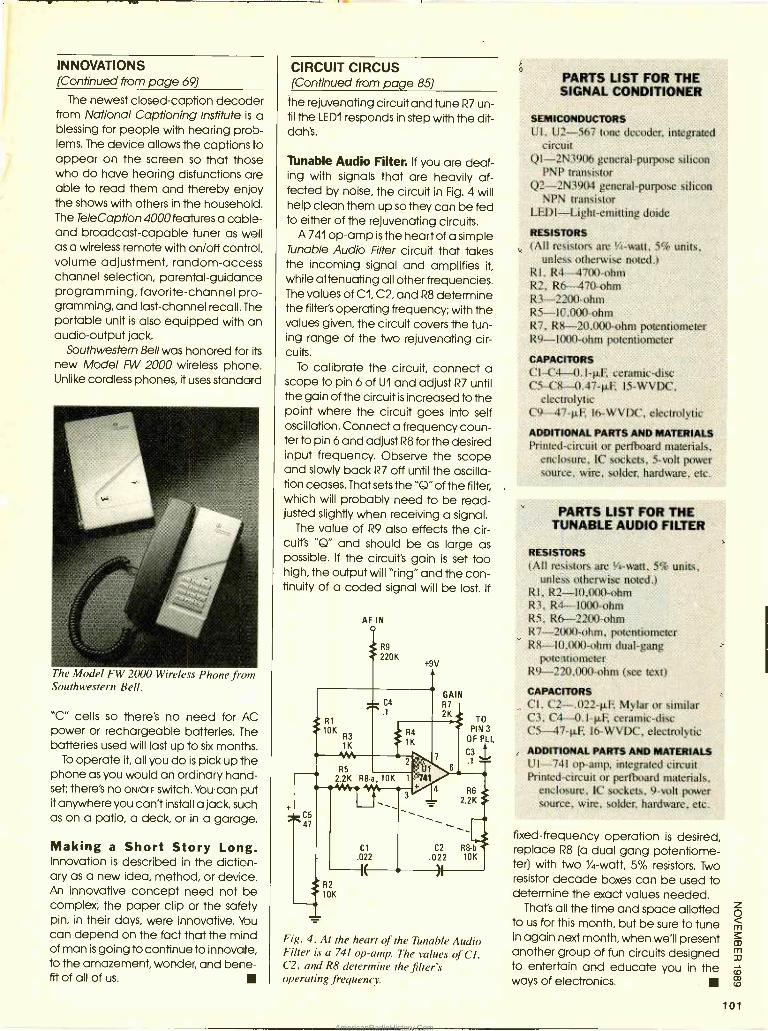
INNOVATIONS (Continued from page 69)
The newest closed- caption decoder from National Captioning Institute is a blessing for people with hearing prob- lems. The device allows the captions to appear on the screen so that those who do have hearing disfunctions are able to read them and thereby enjoy the shows with others in the household. The TeleCaption 4000 features a cable - and broadcast -capable tuner as well as a wireless remote with on /off control, volume adjustment, random -access channel selection, parental -guidance programming, favorite -channel pro- gramming, and last- channel recall. The portable unit is also equipped with an audio -output jack.
Southwestern Bell was honored for its
new Model FW 2000 wireless phone. Unlike cordless phones, it uses standard
The Model FW 2tÍ) 0 Wireless Phone from Southwestern Bell.
"C" cells so there's no need for AC power or rechargeable batteries. The batteries used will last up to six months.
To operate it, all you do is pick up the phone as you would an ordinary hand- set; there's no ON /OFF switch. You can put it anywhere you can't install a jack, such as on a patio, a deck, or in a garage.
Making a Short Story Long. Innovation is described in the diction- ary as a new idea, method, or device. An innovative concept need not be complex; the paper clip or the safety pin, in their days, were innovative. Ybu can depend on the fact that the mind of man is going to continue to innovate, to the amazement, wonder, and bene- fit of all of us.
CIRCUIT CIRCUS (Continued from page 85)
the rejuvenating circuit and tune R7 un- til the LEDI responds in step with the dit - dah's.
Tunable Audio Filter. If you are deal- ing with signals that are heavily af- fected by noise, the circuit in Fig. 4 will help clean them up so they can be fed to either of the rejuvenating circuits.
A 741 op -amp is the heart of a simple Tunable Audio Filter circuit that takes the incoming signal and amplifies it, while attenuating all other frequencies. The values of C1, C2, and R8 determine the filter's operating frequency; with the values given, the circuit covers the tun- ing range of the two rejuvenating cir- cuits.
To calibrate the circuit, connect a scope to pin 6 of U1 and adjust R7 until the gain of the circuit is increased to the point where the circuit goes into self oscillation. Connect a frequency coun- ter to pin 6 and adjust R8 for the desired input frequency. Observe the scope and slowly back R7 off until the oscilla- tion ceases. That sets the "Q" of the filter, which will probably need to be read- justed slightly when receiving a signal.
The value of R9 also effects the cir- cuit's "Q" and should be as large as possible. If the circuit's gain is set too high, the output will "ring" and the con- tinuity of a coded signal will be lost. If
AF IN 0
R9
220K +9V
R1
10K R3 1K
"AN
R5 2.2K R8-a, 10K 1
3
- C4 .- .1
R4
1K
2
vkC5 47
Cl .022
--Ic R2
10K
U1 741
4
GAIN R7
2K TO
PIN 3
OF PLI
C3 .1.
6
.1 > R6
2.2K
C2 R8 b
.022 10K
)1
Fig. 4. At the heart of the Tunable Audio Filter is a 741 op -amp. The values of CI, C2, and R8 determine the filter's operating frequency.
PARTS LIST FOR THE SIGNAL CONDITIONER
SEMICONDUCTORS UI, U2 -567 tone decoder, integrated
circuit QI- 2N3906 general -purpose silicon
PNP transistor Q2- 2N3904 general -purpose silicon
NPN transistor LEDI- Light- emitting doide
RESISTORS (All resistors are %a -watt, 5% units,
unless otherwise noted.) RI. R4 4700 -ohm R2, R6 470 -ohm R3 -2200 -ohm R5- 10,000 -ohm R7, R8- 20,000 -ohm potentiometer R9 -1000 -ohm potentiometer
CAPACITORS CIC/1 - 0.I -RF, ceramic -disc C5C8- 0.47 -µF I5 -WVDC.
electrolytic C9- 47 -µF, 16 -WVDC, electrolytic
ADDITIONAL PARTS AND MATERIALS Printed -circuit or perfboard materials,
enclosure, IC sockets, 5 -volt power source, wire, solder, hardware, etc.
PARTS LIST FOR THE TUNABLE AUDIO FILTER
RESISTORS (All resistors are 1/4-watt, 5% units,
unless otherwise noted.) RI, R2- 10,000 -ohm R3, R4 1000 -ohm R5, R6 -2200 -ohm R7 -2000 -ohm, potentiometer R8- I0,000 -ohm dual -gang
potentiometer R9- 220,000 -ohm (see text)
CAPACITORS CI, C2- .022 -µF, Mylar or similar C3, C4 0.1- .F, ceramic -disc C5- 47 -07, 16 -WVDC, electrolytic
ADDITIONAL PARTS AND MATERIALS U1 -741 op -amp, integrated circuit Printed -circuit or perfboard materials,
enclosure. IC sockets, 9 -volt power source, wire, solder, hardware, etc.
fixed -frequency operation is desired, replace R8 (a dual gang potentiome- ter) with two 1/4 -watt, 5% resistors. Two resistor decade boxes can be used to determine the exact values needed.
That's all the time and space allotted to us for this month, but be sure to tune in again next month, when we'll present another group of fun circuits designed to entertain and educate you in the ways of electronics.
101
AmericanRadioHistory.Com
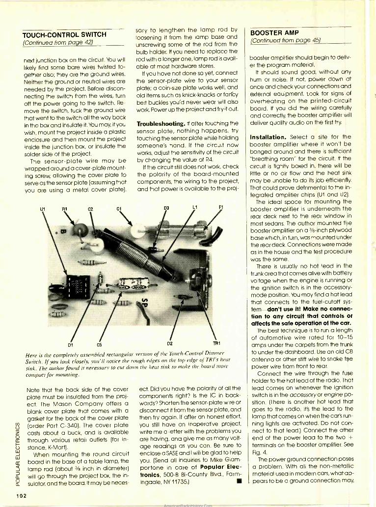
TOUCH -CONTROL SWITCH (Continued from page 42)
next junction box on the circuit. You will
likely find some bare wires twisted to- gether also; they are the ground wires.
Neither the ground or neutral wires are needed by the project. Before discon- necting the switch from the wires, turn
off the power going to the switch. Re-
move the switch, tuck the ground wire that went to the switch all the way back in the box and insulate it. You may, if you
wish, mount the project inside a plastic enclosure and then mount the project inside the junction box, or insulate the solder side of the project.
The sensor -plate wire may be wrapped around a cover -plate mount- ing screw, allowing the cover plate to serve as the sensor plate (assuming that you are using a metal cover plate).
sary to lengthen the lamp rod by loosening it from the lamp base and unscrewing some of the rod from the bulb holder. If you need to replace the rod with a longer one, lamp rod is avail- able at most hardware stores.
If you have not done so yet, connect the sensor -plate wire to your sensor plate; a coin -size plate works well, and old items such as knick- knacks or farfcy belt buckles you'd never wear will also
work. Power up the project and try it out.
Troubleshooting. If after touching the sensor plate, nothing happens, try touching the sensor plate while holding someone's hand. If the circuit now works, adjust the sensitivity of the circuit by changing the value of R4.
If the circuit still does not work, check the polarity of the board -mounted components, the wiring to the project, and that power is available to the proj-
D1 Cb D2 mm1
Here is the completely assembled rectangular version of the Touch- Control Dimmer
Switch. If you look closely, you'll notice the rough edges on the top edge of TRI's heut
sink. The author found it necessary to cut down the heat sink to make the board more
compact for mounting.
102
Note that the back side of the cover plate must be insulated from the proj- ect. The Mason Company offers a
blank cover plate that comes with a gasket for the back of the cover plate (order Part C -340). The cover plate costs about a buck, and is available through various retail outlets (for in-
stance, K- Mart). When mounting the round circuit
board in the base of a table lamp, the lamp rod (about 3/s inch in diameter) will go through the project box, the in-
sulator, and the board. It may be neces-
ect. Did you have the polarity of all the components right? Is the IC in back- wards? Shorten the sensor -plate wire or disconnect it from the sensor plate, and then try again. If after an honest effort, you still have an inoperative project, write me a letter with the problems you
are having, and give me as many volt-
age readings as you can. Be sure to enclose a SASE and I will be glad to help you. (Send all inquiries to Mike Giam- portone in care of Popular Elec- tronics, 500 -B Bi- County Blvd., Farm-
ingdale, NY 11735.)
BOOSTER AMP (Continued from page 45)
booster amplifier should begin to deliv- er the program material.
It should sound good, without any hum or noise. If not, power down at once and check your connections and external equipment. Look for signs of overheating on the printed- circuit board. If you did the wiring carefully and correctly, the booster amplifier will
deliver quality audio on the first try.
Installation. Select a site for the booster amplifier where it won't be banged around and there is sufficient "breathing room" for the circuit. If the circuit is tightly boxed in, there will be little or no air flow and the heat sink
may be unable to do its job efficiently. That could prove detrimental to the in-
tegrated amplifier chips (U1 and U2).
The ideal space for mounting the booster amplifier is underneath the rear deck next to the rear window in
most sedans. The author mounted the booster amplifier on a 3/8 -inch plywood base which, in turn, was mounted under the rear deck. Connections were made as in the house and the test procedure was the same.
There is usually no hot lead in the trunk area that comes alive with battery voltage when the engine is running or the ignition switch is in the accessory - mode position. You may find a hot lead that connects to the fuel -cutoff sys-
tern -don't use it! Make no connec- tion to any circuit that controls or affects the safe operation of the car.
The best technique is to run a length of automotive wire rated for 10 -15 amps under the carpets from the trunk to under the dashboard. Use an old CB
antenna or other stiff wire to snake the power wire from front to rear.
Connect the wire through the fuse
holder to the hot lead of the radio. That lead comes on whenever the ignition switch is in the accessoryor engine po- sition. (There is another hot lead that goes to the radio. It's the lead to the lamp that comes on when the car's run-
ning lights are activated. Do not con- nect to that lead.) Connect the other end of the power lead to the two + terminals on the booster amplifier. See
Fig. 4.
The power ground connection poses
a problem. With all the non -metallic material used in modern cars, what ap- pears to be a ground connection may,
AmericanRadioHistory.Com
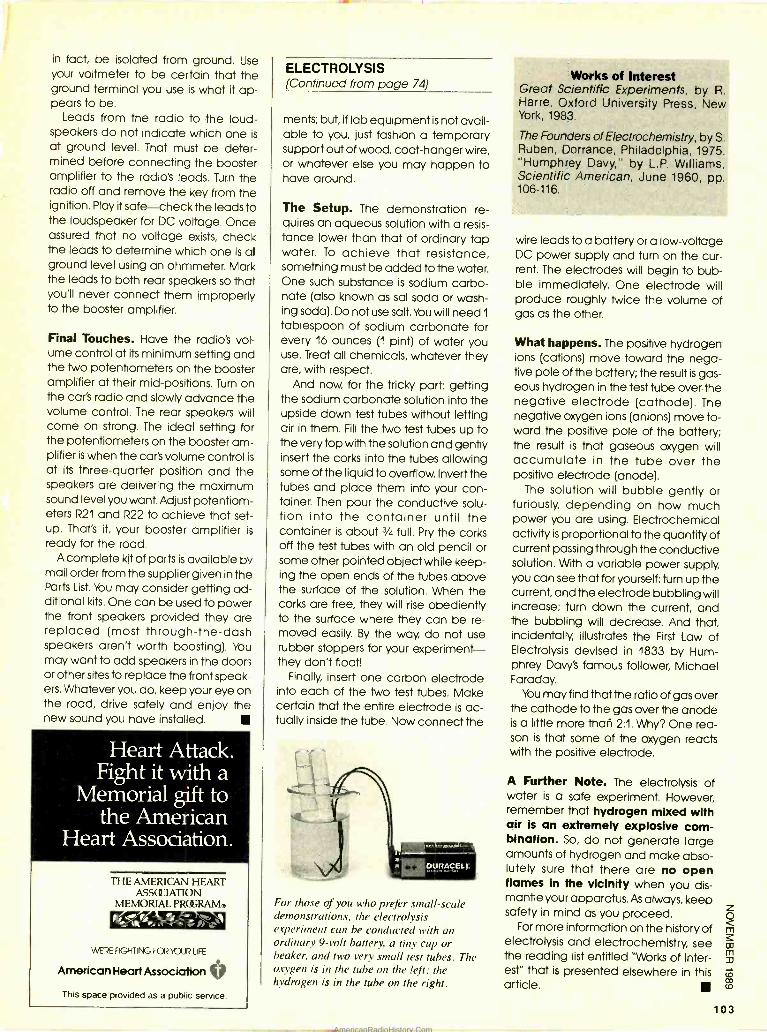
in fact, be isolated from ground. Use your voltmeter to be certain that the ground terminal you use is what it ap- pears to be.
Leads from the radio to the loud- speakers do not indicate which one is
at ground level. That must be deter- mined before connecting the booster amplifier to the radio's leads. Turn the radio off and remove the key from the ignition. Play it safe -check the leads to the loudspeaker for DC voltage. Once assured that no voltage exists, check the leads to determine which one is at ground level using an ohmmeter. Mark the leads to both rear speakers so that you'll never connect them improperly to the booster amplifier.
Final Touches. Have the radio's vol- ume control at its minimum setting and the two potentiometers on the booster amplifier at their mid -positions. Turn on the car's radio and slowly advance the volume control. The rear speakers will come on strong. The ideal setting for the potentiometers on the booster am- plifier is when the car's volume control is
at its three -quarter position and the speakers are delivering the maximum sound level you want. Adjust potentiom- eters R21 and R22 to achieve that set- up. That's it, your booster amplifier is
ready for the road. A complete kit of parts is available by
mail order from the supplier given in the Parts List. You may consider getting ad- ditional kits. One can be used to power the front speakers provided they are replaced (most through- the -dash speakers aren't worth boosting). You may want to add speakers in the doors or other sites to replace the front speak- ers. Whatever you do, keep your eye on the road, drive safely and enjoy the new sound you have installed.
Heart Attack. Fight it with a
Memorial gift to the American
Heart Association.
THE AMERICAN HEART ASSOCIATION
MEMORIAL PROGRAM.
WERE FIGHTING FOR 'CUR LIFE
American Heart Association V This space provided as a public service.
ELECTROLYSIS (Continued from page 74)
ments; but, if lab equipment is not avail- able to you, just fashion a temporary support out of wood, coat -hanger wire, or whatever else you may happen to have around.
The Setup. The demonstration re- quires an aqueous solution with a resis- tance lower than that of ordinary tap water. To achieve that resistance, something must be added to the water. One such substance is sodium carbo- nate (also known as sal soda or wash- ing soda). Do not use salt. You will need 1
tablespoon of sodium carbonate for every 16 ounces (1 pint) of water you use. Treat all chemicals, whatever they are, with respect.
And now, for the tricky part: getting the sodium carbonate solution into the upside down test tubes without letting air in them. Fill the two test tubes up to the very top with the solution and gently insert the corks into the tubes allowing some of the liquid to overflow. Invert the tubes and place them into your con- tainer. Then pour the conductive solu- tion into the container until the container is about 3/4 full. Pry the corks off the test tubes with an old pencil or some other pointed object while keep- ing the open ends of the tubes above the surface of the solution. When the corks are free, they will rise obediently to the surface where they can be re- moved easily. By the way, do not use rubber stoppers for your experiment - they don't float!
Finally, insert one carbon electrode into each of the two test tubes. Make certain that the entire electrode is ac- tually inside the tube. Now connect the
For those of you who prefer small-scale demonstrations, the electrolysis experiment can be conducted with an ordinary 9 -volt battery, a tiny cup or beaker, and two very small test tubes. The oxygen is in the tube on the left: the hydrogen is in the tube on the right.
Works of Interest Great Scientific Experiments, by R. Harre, Oxford University Press, New York, 1983.
The Founders of Electrochemistry, by S. Ruben, Dorrance, Philadelphia, 1975. "Humphrey Davy," by L.P. Williams, Scientific American, June 1960, pp. 106 -116.
wire leads to a battery or a low- voltage DC power supply and turn on the cur- rent. The electrodes will begin to bub- ble immediately. One electrode will produce roughly twice the volume of gas as the other.
What happens. The positive hydrogen ions (cations) move toward the nega- tive pole of the battery; the result is gas- eous hydrogen in the test tube over the negative electrode (cathode). The negative oxygen ions (anions) move to- ward the positive pole of the battery; the result is that gaseous oxygen will accumulate in the tube over the positive electrode (anode).
The solution will bubble gently or furiously, depending on how much power you are using. Electrochemical activity is proportional to the quantity of current passing through the conductive solution. With a variable power supply, you can see that for yourself: turn up the current, and the electrode bubbling will increase; turn down the current, and the bubbling will decrease. And that, incidentally, illustrates the First Law of Electrolysis devised in 1833 by Hum- phrey Davy's famous follower, Michael Faraday.
You may find that the ratio of gas over the cathode to the gas over the anode is a little more than 2:1. Why? One rea- son is that some of the oxygen reacts with the positive electrode.
A Further Note. The electrolysis of water is a safe experiment. However, remember that hydrogen mixed with air is an extremely explosive com- bination. So, do not generate large amounts of hydrogen and make abso- lutely sure that there are no open flames in the vicinity when you dis- mantle your apparatus. As always, keep safety in mind as you proceed.
For more information on the history of electrolysis and electrochemistry, see the reading list entitled "Works of Inter- est" that is presented elsewhere in this article.
103
AmericanRadioHistory.Com
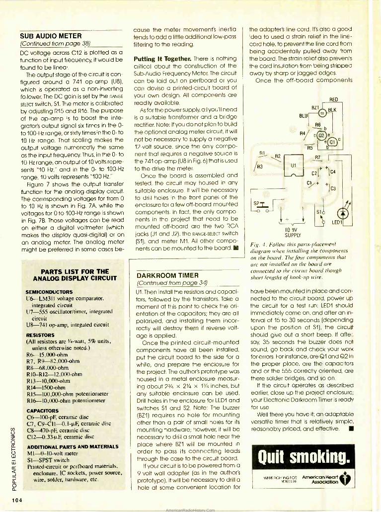
SUB AUDIO METER (Continued from page 38)
DC voltage across C12 is plotted as a function of input frequency, it would be found to be linear.
The output stage of the circuit is con- figured around a 741 op -amp (U8),
which is operated as a non -inverting follower. The DC gain is set by the RANGE
SELECT switch, S1. The meter is calibrated by adjusting R15 and R16. The purpose of the op -amp is to boost the inte- grator's output signal six times in the 0-
to 100 -Hz range, or sixty times in the 0- to 10 -Hz range. That scaling makes the output voltage numerically the same as the input frequency. Thus, in the 0- to 10 -Hz range, an output of 10 volts repre- sents "10 Hz," and in the 0- to 100 -Hz
range, 10 volts represents "100 Hz."
Figure 7 shows the output transfer function for the analog -display circuit. The corresponding voltages for from 0
to 10 Hz is shown in Fig. 7A, while the voltages for O to 100 -Hz range is shown in Fig. 7B. Those voltages can be read on either a digital voltmeter (which makes the display quasi -digital) or on an analog meter. The analog meter might be preferred in some cases be-
104
PARTS LIST FOR THE ANALOG DISPLAY CIRCUIT
SEMICONDUCTORS U6 -LM311 voltage comparator,
integrated circuit U7 -555 oscillator /timer, integrated
circuit U8 -741 op -amp, integated circuit
RESISTORS (All resistors are 1/4-watt, 5% units,
unless otherwise noted.) R6- 15,000 -ohm R7, R9- 82,000 -ohm R8- 68,000 -ohm R10- R12- 12,000 -ohm R13- 10,000 -ohm R14-1500-ohm R15- 100,000 -ohm potentiometer R16- 10,000 -ohm potentiometer
CAPACITORS C6- 100 -pF, ceramic disc C7, C9- C11- 0.1 -µF, ceramic disc C8- 1170 -pF ceramic disc C12- 0.33 -p-F, ceramic disc
ADDITIONAL PARTS AND MATERIALS MI -0-10 -volt meter SI -SPST switch Printed- circuit or perfboard materials,
enclosure, IC sockets, power source, wire, solder, hardware, etc.
cause the meter movement's inertia tends to add a little additional low -pass
filtering to the reading.
Putting It Together. There is nothing critical about the construction of the Sub -Audio Frequency Meter. The circuit can be laid out on perfboard or you can devise a printed -circuit board of your own design. All components are readily available.
As for the power supply, all you'll need is a suitable transformer and a bridge rectifier. Note: If you do not plan to build the optional analog meter circuit, it will
not be necessary to supply a negative 12 -volt source, since the only compo- nent that requires a negative source is
the 741 op -amp (U8 in Fig. 6) that is used to the drive the meter.
Once the board is assembled and tested, the circuit may housed in any suitable enclosure. It will be necessary to drill holes in the front panel of the enclosure for a few off -board -mounted components. In fact, the only compo- nents in the project that need to be mounted off -board are the Iwo RCA
jacks (J1 and J2), the RANGE- SELECT switch (S1), and meter Ml. All other compo- nents can be mounted to the board.
DARKROOM TIMER (Continued from page 34)
U1. Then install the resistors and capaci- tors, followed by the transistors. Take a moment at this point to check the ori- entation of the capacitors; they are all polarized, and installing them incor- rectly will destroy them if reverse volt-
age is applied. Once the printed- circuit -mounted
components have all been installed, put the circuit board to the side for a while, and prepare the enclosure for the project. The author's prototype was housed in a metal enclosure measur- ing about 23/4 x 21/4 x 13/4 inches, but any suitable enclosure can be used. Drill holes in the enclosure for LEDI and switches S1 and S2. Note: The buzzer (BZ1) requires no hole for mounting other than a pair of small holes for its
mounting hardware; however, it will be necessary to drill a small hole near the place where BZ1 will be mounted in
order to pass its connecting leads through the case to the circuit board.
If your circuit is to be powered from a 9 -volt wall adapter (as in the author's prototype), it will be necessary to drill a hole at some convenient location for
the adapter's line cord. It's also a good idea to used a strain relief in the line - cord hole, to prevent the line cord from being accidentally pulled away from the board. The strain relief also preven-s the cord insulation from being stripped away by sharp or jagged edges.
Once the off -board components
\ /R3
S2
U1
RED
S10 1'j
LEDI
TO 9V SUPPLY
Fig. 4. Follow this parts -placement diagram when installing the components on the board. The four components that are not installed on the board are connected to the circuit board though short lengths of hook -up wire.
have been mounted in place and con- nected to the circuit board, power up the circuit for a test run: LEDI should immediately come on, and after an in- terval of 15 to 30 seconds (depending upon the position of S1), the circuit should give out a short beep. If after, say, 35 seconds the buzzer does not sound, go back and check your work for errors. For instance, are Q1 and Q2 in
the proper place, are the capacitors and or the 555 correctly oriented, are there solder bridges, and so on.
If the circuit operates as described earlier, close up the project enclosure; your Electronic Darkroom Timer is ready for use.
Well there you have it; an adaptable versatile timer that is relatively simple, reasonably priced, and effective.
AmericanRadioHistory.Com
There is a way to get help when you need it. The American Home Satellite Association. An organization created exclusively to protect and enhance your enjoyment of your satellite TV system.
Take our toll free "Helpline, for example. Flom locating satellite signals to locating a reputable dealer, help is just a phone call away. ARSA provides educational videotapes and informative books, too. At very special member prices.
Plus, 10 times a year, AHSA's official newsletter, Sky Repor4 will bring you the latest word on products, legislation, programming, and more. Not to mention reviews of new products and services. And that's not all AHSA has in store for you.
Programming shouldn't cost a fortune. With AHSA's group buying power,
you can save on premium services, superstations and basic programming services. Enjoy savings on accessories, equipment, and programming guides, too.
You're not alone anymore! With your voice behind us, AHSA is
promoting legislation to guarantee fair access at reasonable prices. Addressing zoning and piracy issues. Even sending expert witnesses to Congressional hearings. Join other dish owners around the nation, and become a force to be reckoned with.
D Rush my free information kit. Name
Address
City State Zip
Sign me up right away and send my complete membership kit.
Check enclosed for $36 (made out to AHSA) Bill my VISA MasterCard Card # Exp. Date Authorized Signature X
30 -day Money Back Guarantee
Return completed coupon to: American Home Satellite Association, Inc., Suite 800, 500108th Ave. NE,
American Home Bellevue,WA 98004 -5560 Or call Toll Free
Satellite Association 1 -800- 321 -AHSA (2472). CA
105
AmericanRadioHistory.Com
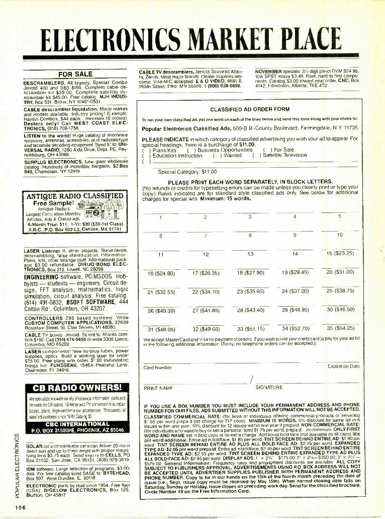
ELECTRONICS MARKET PLACE
FOR SALE DESCRAMBLERS. All brands. Special: Combo Jerrold 400 and SB3 $165. Complete cable de- scrambler kit $39.00. Complete satellite de- scrambler kit $45.00. Free catalog. MJH INDUS- TRY, Box 531, Bronx, NY 10461 -0531.
CABLE descrambier liquidation. Major makes and models available. Industry pricing! (Example: Hamlin Combo's, $44 each... minimum 10 orders). Dealers only! Call WEST COAST ELEC- TRONICS, (818) 709 -1758.
LISTEN to the world! Huge catalog of shortwave receivers, antennas, acessories, plus radioteletype and facsimile decoding equipment. Send $1 to: UNI- VERSAL RADIO, 1280 Aida Drive, Dept. PE, Rey - noldsburg, OH 43068.
SURPLUS ELECTRONICS. New giant wholesale catalog. Hundreds of incredible bargains. $2.Box 840, Champlain, NY 12919.
ANTIQUE RADIO CLASSIFIED Free Sample!
Antique Radio's Largest Circulation Monthly. Articles, Ads & Classifieds. 6 -Month Trial: $11. 1 -Yr: $20 ($30 -1st Class). A.R.C., P.O. Box 802 -L3, Carlisle, MA 01741
LASER Listener II, other projects. Surveillance, descrambling, false identification, information. Plans, kits, other strange stuff. Informational pack- age $3.00 refundable. DIRIJO /BOND ELEC- TRONICS, Box 212, Lowell, NC 28098.
ENGINEERING software, PC /MSDOS. Hob-
byists - students - engineers. Circuit de-
sign, FFT analysis, mathematics, logic simulation, circuit analysis. Free catalog, (614) 491 -0832, BSOFT SOFTWARE, 444
Colton Rd., Columbus, OH 43207.
CONTROLLERS Z80 based systems. Write CUSTOM COMPUTER APPLICATIONS, 22639 Rosedale Street, St. Clair Shores, MI 48080.
CABLE TV boxes. Jerrold, Scientific Atlanta com- bo's $150. Call (314) 474 -5656 or write 3309 Lance, Columbia, MO 65202.
LASER components! New surplus tubes, power supplies, optics. Build a working laser for under $75.00. Free plans with order. $1.00 (refundable) brings list. FUNDSERV, 1546A Peaceful Lane, Clearwater, FL 34616.
CB RADIO OWNERS! We specialize in a wide variety of technical information, parts and
services for CB radios. 10-Meter and FM conversion kits, repair
books, plans, high -performance accessories. Thousands of
satisfied customer since 1976! Catalog $2.
CBC INTERNATIONAL P.O. BOX 31500PE, PHOENIX, AZ 85046
106
SOLAR cells concentrator cells can deliver 20 ma in
direct sun and up to three amps with proper magni- fying lens $3.75 each. Send inquiry to CELLS, PO Box 21532, San Jose, CA 95151. (408) 929 -3619.
IBM software. Large selection of programs. $3.001 disk. For free catalog send SASE to: BYTEHEAD, Box 597, West Dundee, IL, 60118.
ELECTRONIC parts by mail since 1954. Free flyer (USA). BIGELOW ELECTRONICS, Box 125, Bluffton, OH 45817.
CABLE TV descramblers, Jerrold, Scientific Atlan- ta, Zenith. Most major brands. Dealer inquiries wel- come. Visa -M /C accepted. E & O VIDEO, 9691 E.
265th Street, Elko, MN 55020. 1 (800) 638 -6898.
NOVEMBER specials: 3V2 digit panel DVM $24.95, 10A SPST relays $3.49. Rare, hard to find compo- nents. Catalog $3.00 toward next order. CNC, Box 4142, Edmonton, Alberta, T6E 472.
CLASSIFIED AD ORDER FORM
To run your own classified ad, put one word on each of the lines below and send this form along with your check to:
Popular Electronics Classified Ads, 500 -B Bi- County Boulevard, Farmingdale, N.Y. 11735
PLEASE INDICATE in which category of classified advertising you wish your ad to appear. For
special headings, there is a surcharge of $11.00. ( ) Plans /Kits ( ) Business Opportunities ( ) For Sale ( ) Education /Instruction ( ) Wanted ( ) Satellite Television
)
Special Category: $11.00
PLEASE PRINT EACH WORD SEPARATELY, IN BLOCK LETTERS. (No refunds or credits for typesetting errors can be made unless you clearly print or type your copy.) Rates indicated are for standard style classified ads only. See below for additional charges for special ads. Minimum: 15 words.
1 2 3 4 5
6 7 8 9 10
11 12 13 14 15 ($23.25)
16 ($24.80) 17 ($26.35) 18 ($27.90) 19 ($29.45) 20 ($31.00)
21 ($32.55) 22 ($34.10) 23 ($35.65) 24 ($37.20) 25 ($38.75)
26 ($40.30) 27 ($41.85) 28 ($43.40) 29 ($44.95) 30 ($46.50)
31 ($48.05) 32 ($49.60) 33 ($51.15) 34 ($52.70) 35 ($54.25)
We accept MasterCard and Visa for payment of orders. If you wish to use your credit card to pay for your ad fill in the following additional information (Sorry, no telephone orders can be accepted.):
Card Number Expiration Date
PRINT NAME SIGNATURE
IF YOU USE A BOX NUMBER YOU MUST INCLUDE YOUR PERMANENT ADDRESS AND PHONE NUMBER FOR OUR FILES. ADS SUBMITTED WITHOUT THIS INFORMATION WILL NOT BE ACCEPTED.
CLASSIFIED COMMERCIAL RATE: (for firms or individuals offering commercial products or services) $1.55 per word prepaid (no charge for ZIP code)...MINIMUM 15 WORDS. 5% discount for same ad in 6
issues within one year; 10% discount for 12 issues within one year if prepaid. NON -COMMERCIAL RATE:
(for individuals who want to buy or sell a personal item) $1.25 per word, prepaid....no minimum. ONLY FIRST
WORD AND NAME set in bold caps at no extra charge. Additional bold face (not available as all caps) 30e per word additional. Entire ad in boldface, $1.85 per word. TINT SCREEN BEHIND ENTIRE AD: $1.90 per
word. TINT SCREEN BEHIND ENTIRE AD PLUS ALL BOLD FACE AD: $2.25 per word. EXPANDED TYPE AD: $2.05 per word prepaid. Entire ad in boldface, $2.45 per word. TINT SCREEN BEHIND ENTIRE EXPANDED TYPE AD: $2.55 per word. TINT SCREEN BEHIND ENTIRE EXPANDED TYPE AD PLUS
ALL BOLD FACE AD: $2.95 per word. DISPLAY ADS:1" x 21/4'- $175.00; 2" x 21/4- $350.00; 3" x 21/4"-
$525.00. General Information: Frequency rates and prepayment discounts are available. ALL COPY
SUBJECT TO PUBLISHERS APPROVAL. ADVERTISEMENTS USING P.O. BOX ADDRESS WILL NOT
BE ACCEPTED UNTIL ADVERTISER SUPPLIES PUBLISHER WITH PERMANENT ADDRESS AND
PHONE NUMBER. Copy to be in our hands on the 15th of the fourth month preceding the date of issue (i.e.; Sept. issue copy must be received by May 15th). When normal closing date falls on
Saturday, Sunday or Holiday, issue closes on preceding work day. Send for the classified brochure. Circle Number 49 on the Free Information Card.
AmericanRadioHistory.Com
FREE power supply, connectors ($8.95 value) with TV project assortment #103 (RE's February 1984 G. Sync article) contains PCB, TOKO coils, transistors (BFQ85), IC's, diodes, article reprint. $25.00. Five /$112.50. Assortment #104 contains all other parts $10.00. Shipping $3.00. MCNisa, COD accepted. JIM RHODES, INC., PO Box 3421, Bristol, TN 37625.
PC- OSCILLOSCOPE for only $259.00. Turn your PC, PC -XT, PC -AT or compatible into a powerful 25MHz digital storage oscilloscope. Write for free information or send $5.00 for demo package to: CHASE SCIENTIFIC COMPANY, Box 1895, AAptos, CA 95001.
PLANS & KITS ELECTRONIC kits! Transmitters! Recorders! Phone devices! Bug detectors! Surveillance items! More! Catalog $1.00: XANDI ELECTRONICS, Box 25647, 32HH, Tempe AZ 85285 -5647.
SPEAKERS - subwoofers, woofers, midranges, tweeters for auto, home, MI, commercial applica- tions. 88 page color catalog - $2.00. Amplifiers, microphones, DJ equipment. McGEE RADIO, 1901 McGee, Kansas City, MO 64108.
PRINTED circuit boards etched & drilled. Free deliv- ery. K & F ELECTRONICS, INC., 33041 Groesbeck, Fraser, MI 48026. (313) 294 -8720.
CATALOG: hobby /broadcasting/HAM /CB: Cable TV, transmitters, amplifiers, surveillance devices, computers, morel PANAXIS, Box 130 -H11, Para- dise, CA 95967.
PROJECTION TV Convert your TV to project 7 foot picture... Easy!... Results comparable to $2,500 projectors... Plans and 8" Lens $24.95... Profes- sional systems available... Illustrated catalog free. MACROCOMA, 15HC Main Street, Washington Crossing, PA 18977. Creditcard orders 24 hrs. (215) 736 -3979.
KIT catalog - Automotive, audio, phone, sports, surveillance, test. Catalog $1.00. BALLco, PO Box 1078, Snellville, GA 30278 -1078.
SHORT -wave -craft. 1933. One-tube DX radio. Free plans from BOB RYAN, PO Box 3039, Anaheim, CA 92803.
STAINED glass starter kit. Send for free details. ASTROSOFT, 15006 La Mesa Street, Sylmar, CA 91342.
BOARDS for Popular Electronics and Radio -Elec- tronics projects. Inexpensive! Free Information! INDUSTRIAL MICRO, Box 596, Logan, Utah 84321.
TV FILTERS T.V. tunable notch filters. Free brochure. D. K. VID- EO, Box 63/6025, Margate, FL 33063. (305) 752 -9202.
DIGITAL CAR DASHBOARDS BUILD yourself complete electronic dashboards. Informational package: $2.00 (rufundable). MOD- ERN LABS, 2900 -F Ruisseau, Saint- Elizabeth, QC, JOK 2J0, Canada.
KIT TRONICS FREE shipping when ordering any kit advertised. Dual Variable power supply 0 -24V, 0 -1A, ripple - free, PS -024 only $57.39 ($49.95 US) function generator 0 -1MHz, sine, triangle, square waves. Separate TTL, AM, FM, outputs. Power supply, alu- minum chassis box, and even solder included. FG -100 just $89.95 ($74.95 US). Kits comes with 90 day warranty. Kit -Tronics, carries tools, books, test -equipment, chemicals, semiconductors, and kits. Send for free information. Retailers and schools welcomed. C.O.D.'S available in Canada only, add $3.00. Send cheque, money order or Visa informa- tion to: KIT -TRONICS, L.B. 141, LaPrairie, Quebec, J5R 3Y2.
WANTED, dealers to distribute Kit -Tronic's prod- ucts. Send for free information ($5 for samples). KIT TRONICS SUPPLY, 69 Perras, St- Constant, Quebec, J5A 2E9.
CABLE T.V. CONVERTERS WHY PAY A HIGH MONTHLY FEE?
All Jerrold, Oak, Hamlin, Zenith, Scientific Atlanta, Magnavox and all specialized cable equipment available for shipment within 24 hours. For fast service MC / VISA or C.O.D. telephone orders accepted (800) 648 -3030 60 Day Guarantee (Quantity Discounts) 8 A.M. to 5 P.M. C.S.T. CLOSED WEEK- ENDS. Send self -addressed Stamped enve- lope (600 postage) for Catalog.
TI WEST P.O. Box 5000
ELKTROf1KS Inc. Suite 311 (PE)
Carpentersville, IL 60110
No Illinois Orders Accepted.
SATELLITE TV FREE catalog. Systems, upgrades, Houston, Uni - den, Chapparal, etc. Save $$$$$. SKYVISION, 2008 Collegeway, Fergus Falls, MN 56537. (218) 739 -5231.
FREE 36 page catalog. Americas largest! All major brands. Save 40 - 60 %. Since 1977 nobody under- sells WEST INC., 1741 Cedardale Road, Mt. Ver- non, WA 98273. Visa/MC /Disc/Amex/COD. 1 (800) 222 -9064.
CABLE -TV BOXES Descramblers Converters
FREE CATALOG TRANS -WORLD CABLE CO.
12062 Southwest 117th Ct., Suite 126 Miami, Florida 33186
800 -442 -9333
COMPUTERS AMIGA/Commodore chips. 8364(Paula) - $56.95, 8362(Denise) - $56.95, 8370(F.agnus) - $61.50, 8520A1- $17.95, 6526 - $12.95, 6581- $11.95, PIA - $12.95, 901226 - $9.50, 6567 - $17.95. Heavy duty replacement power supply C64 - $22.50. Newly revised, just released, the Com- modore Diagnostian II fantastic reference guide for fixing all Commodore computers. (10,000 sold) $6.95 postpaid. Free catalog, Mastercard /Visa. GRAPEVINE GROUP, INC., 35 Charlotte Drive, Wesley Hills, NY 10977. 1 (800) 292 -7445.
WANTED INVENTORS! Call IMPAC -We submit ideas to manufacturers! For free information package call toll free in U.S. and Canada 1 (800) 225 -5800.
CABLE EQUIPMENT CABLE TV Secrets - the outlaw publication the cable companies tried to ban. HBO, Movie Channel, Showtime, descramblers, converters, etc. Sup- pliers list included. $8.95. CABLE FACTS, Box 711 - H, Pataskala, OH 43062.
BUSINESS OPPORTUNITIES EASY work! Excellent pay! Assemble products at home. Call for info. (504) 641 -8003 Ext. 5730.
WARNING salaried jobs are hazardous to wealth. Fabulous home business, no selling, no inventory, no overhead. $144,000 per year easy. Write: LAKE, 1740 So. Pecan Circle, Dept. EM, Mesa, AZ 85202.
CABLE TV CONVERTERS IN STOCK
Stocking all types of converters - Panasonic, Jerrold, Tocom, Pioneer,
Scientific Atlanta, Zenith, Oak, Hamlin, Eagle, and others brands available.
Call or write for FREE CATALOG 10 am - 6 pm Eastern, Mon. - Fri.
VIDEO -LINK Enterprises, Inc. 165 WEST PUTNAM AVE. GREENWICH, CT 06830 Phone (203) 622 -4386
YOUR own radio station! AM, FM, TV, cable. Li- censed /unlicensed. BROADCASTING, Box 130 - H11, Paradise, Ca 95967.
INVENTIONS, ideas, technology wanted for pre- sentation to industry/exhibition at national innova- tion exposition. Call 1 (800) 288 -IDEA. ASSEMBLE digital dashboards. Details $2.00. MODERN LABS, Digidash Division, 2900 Ruisseau, Saint -Elizabeth, Quebec, JOK 2J0, Can- ada.
MAKE $75,000 to $250,000 yearly or more fixing IBM color monitors. No investment, Start doing it from your home (a telephone required). Infor- mation, USA, Canada $1.00, Europe or other countries $8.00, US funds. RANDALL DISPLAY, Box 2168 -H, Van Nuys, CA 91404, USA.
NEW HE NE LASER TUBES $35
Dealer Inquiries Invited. Free Catalog!
MEREDITH INSTRUMENTS: 6403 N. 59th Ave. Glendale, AZ 85301 (602) 934 -9387
"Me Source for Laser Surplus"
TUBES - 2000 TYPES DISCOUNT PRICES!
Early, hard -to-find, and modern tubes. Also transformers, capacitors and parts for tube equipment. Send $2.00
r for 24 page wholesale catalog.
ANTIQUE ELECTRONIC SUPPLY 688 W. First St.Tempe, AZ 85281.602/894 -9503
EDUCATION /INSTRUCTION MAGIC! Four illustrated lessons plus inside infor- mation shows you how. We provide almost 50 tricks including equipment for four professional effects. You get a binder to keep the materials in, and a one - year membership in the International Performing Magicians with a plastic membership card that has your name gold -embossed. You get a one -year sub- scription to our quarterly newsletter, "IT'S MAGIC!" Order now! $29.95 for each course + $3.50 postage and handling. (New York residents add applicable state and local sales tax). The Magic Course, 500 - B BiCounty Blvd., Farmingdale, NY 11735.
LEARN IBM PC assembly language. 80 pro- grams. Games, quizzes, animation, utilities. In- cludes license. 360K $5.00, 720K $6.00, Book $18.00. ZIPFAST, Box 12238, Lexington, KY 40581 -2238.
F.C.C. Commercial General Radiotelephone Li- cense. Electronics home study. Fast, inexpensive! "Free" details. COMMAND, D -178, Box 2824, San Francisco, CA 94126.
CCD Video camera. Learn how imaging IC's work and how to use them to build a low cost video camera. Send $19.95, VITRONICS, PO Box 7, Sta- tion G, Calgary, Alberta T3A 2G1.
LEARN VCR service today! We make it easy! 90 minute video tape cleanings and servicing $31.95. SALCO, 318 Mesa Verde, Palmdale, CA 93551. Visa/MC accepted.
107 AmericanRadioHistory.Com
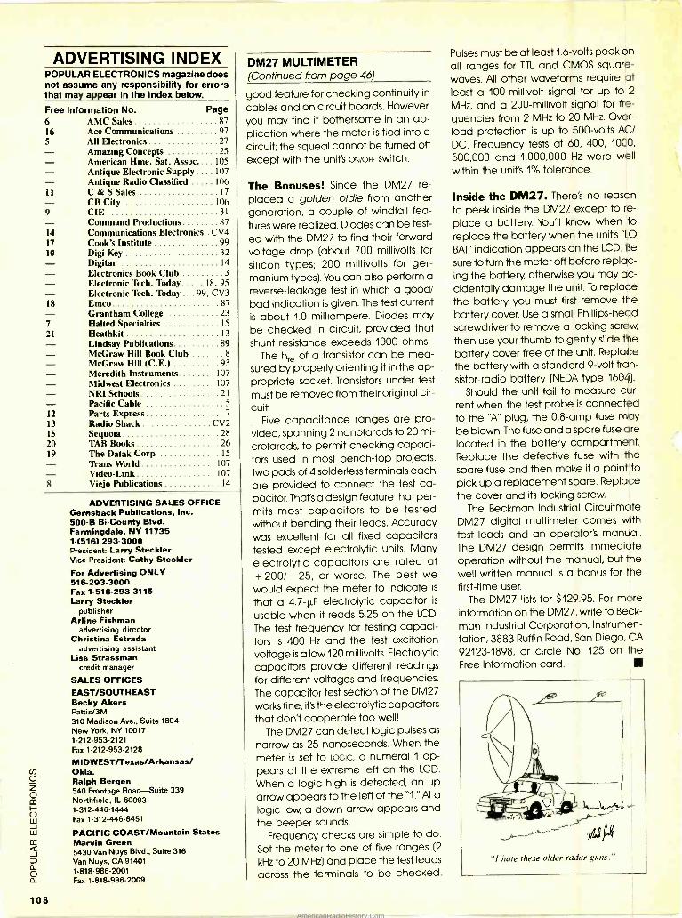
ADVERTISING INDEX POPULAR ELECTRONICS magazine does not assume any responsibility for errors that may appear in the index below.
Free Information No. Page 6 AMC Sales 87 16 Ace Communications 97 5 All Electronics 27 - Amazing Concepts 25 - American Hme. Sat. Assoc.... 105 - Antique Electronic Supply .... 107 - Antique Radio Classified 106 11 C & S Sales 17 - CB City 106 9 CIE 31 - Command Productions 87 14 Communications Electronics . CV4 17 Cook's Institute 99 10 Digi Key 32 - Digitar 14 - Electronics Book Club 3
Electronic Tech. Today 18, 95 - Electronic Tech. Today .. 99, CV3 18 Emco 87 - Grantham College 23 7 Halted Specialties 15
21 Heathkit 13 - Lindsay Publications 89 McGraw Hill Book Club 8
McGraw Hill (C.E ) 93 Meredith Instruments 107 Midwest Electronics 107 - NRI Schools 21 - Pacific Cable 5
12 Parts Express 7
13 Radio Shack CV2 15 Sequoia 28 20 TAB Books 26 19 The Datak Corp 15 - Trans World 107 - Video -Link 107
8 Viejo Publications 14
108
ADVERTISING SALES OFFICE Gernsback Publications, Inc. 500 -B Bi- County Blvd. Farmingdale. NY 11735 1 -[516) 293-3000 President: Larry Steckler Vice President: Cathy Steckler For Advertising ONLY 516- 293 -3000 Fax 1- 516- 293 -3115 Larry Steckler
publisher Arline Fishman
advertising director Christina Estrada
advertising assistant Lisa Strassman
credit manager
SALES OFFICES EAST /SOUTHEAST Becky Akers Pattis/3M 310 Madison Ave., Suite 1804 New York, NY 10017 1- 212- 953 -2121 Fax 1- 212 -953 -2128
MIDWEST/Texas/Arkansas/ Okla. Ralph Bergen 540 Frontage Road -Suite 339 Northfield, IL 60093 1-312-446-1444 Fax 1- 312 -446 -8451
PACIFIC COAST /Mountain States Marvin Green 5430 Van Nuys Blvd., Suite 316 Van Nuys, CA 91401 1-818-986-2001 Fax 1-818-986-2009
DM27 MULTIMETER (Continued from page 46)
good feature for checking continuity in
cables and on circuit boards. However,
you may find it bothersome in an ap- plication where the meter is tied into a
circuit; the squeal cannot be turned off except with the unit's ON /OFF switch.
The Bonuses! Since the DM27 re-
placed a golden oldie from another generation, a couple of windfall fea-
tures were realized. Diodes c'an be test-
ed with the DM27 to find their forward voltage drop (about 700 millivolts for
silicon types; 200 millivolts for ger- manium types). You can also perform a
reverse -leakage test in which a good/ bad indication is given. The test current is about 1.0 milliampere. Diodes may be checked in circuit, provided that shunt resistance exceeds 1000 ohms.
The hte of a transistor can be mea- sured by properly orienting it in the ap- propriate socket. Transistors under test
must be removed from their original cir-
cuit. Five capacitance ranges are pro-
vided, spanning 2 nanofarads to 20 mi-
crofarads, to permit checking capaci- tors used in most bench -top projects. Two pads of 4 solderless terminals each are provided to connect the test ca- pacitor. That's a design feature that per- mits most capacitors to be tested without bending their leads. Accuracy was excellent for all fixed capacitors tested except electrolytic units. Many
electrolytic capacitors are rated at + 200/ - 25, or worse. The best we would expect the meter to indicate is
that a 4.7 -11F electrolytic capacitor is
usable when it reads 5.25 on the LCD.
The test frequency for testing capaci- tors is 400 Hz and the test excitation voltage is a low 120 millivolts. Electrolytic capacitors provide different readings for different voltages and frequencies. The capacitor test section of the DM27
works fine, it's the electrolytic capacitors that don't cooperate too well!
The DM27 can detect logic pulses as
narrow as 25 nanoseconds. When the meter is set to LOGIC, a numeral 1 ap- pears at the extreme left on the LCD.
When a logic high is detected, an up
arrow appears to the left of the "1." At a
logic low, a down arrow appears and the beeper sounds.
Frequency checks are simple to do.
Set the meter to one of five ranges (2
kHz to 20 MHz) and place the test leads
across the terminals to be checked.
Pulses must be at least 1.6 -volts peak on all ranges for TTL and CMOS square - waves. All other waveforms require at least a 100 -millivolt signal for up to 2
MHz, and a 200 -millivolt signal for fre-
quencies from 2 MHz to 20 MHz. Over-
load protection is up to 500 -volts AC/
DC. Frequency tests at 60, 400, 1000,
500,000 and 1,000,000 Hz were well within the unit's 1% tolerance.
Inside the DM27. There's no reason
to peek inside the DM27 except to re-
place a battery. You'll know when to replace the battery when the unit's "LO
BAT" indication appears on the LCD. Be
sure to turn the meter off before replac- ing the battery, otherwise you may ac- cidentally damage the unit. To replace the battery you must first remove the battery cover. Use a small Phillips -head screwdriver to remove a locking screw,
then use your thumb to gently slide the battery cover free of the unit. Replace the battery with a standard 9 -volt tran- sistor -radio battery (NEDA type 1604).
Should the unit fail to measure cur- rent when the test probe is connected to the "A" plug, the 0.8 -amp fuse may be blown. The fuse and a spare fuse are located in the battery compartment. Replace the defective fuse with the spare fuse and then make it a point to pick up a replacement spare. Replace the cover and its locking screw.
The Beckman Industrial Circuitmate DM27 digital multimeter comes with test leads and an operator's manual. The DM27 design permits immediate operation without the manual, but the well written manual is a bonus for the first -time user.
The DM27 lists for $129.95. For more information on the DM27, write to Beck-
man Industrial Corporation, Instrumen- tation, 3883 Ruffin Road, San Diego, CA
92123 -1898, or circle No. 125 on the Free Information card.
"1 hate these older radar guns."
AmericanRadioHistory.Com
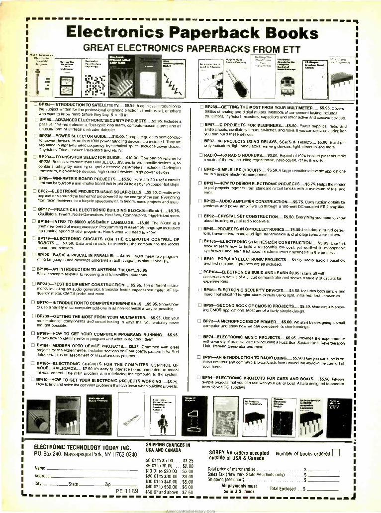
MINOietl00 iNegendif SOttIMe
!It
r
More M,vonced Vectronm Security Pcoioc.
Electronics Paperback Books GREAT ELECTRONICS PAPERBACKS FROM ETT
An introductron to
\} \
AI (IC Chat ae.,e. P,aìneeR
ID** OtreWYrtrlr M er WtW1YYwe
BP195- INTRODUCTION TO SATELLITE TV..... $9.95. A definitive introduction to the subject written for the professional engineer, electronics enthusiast, or others who want to know more before they buy. 8 x 10 in. BP190- ADVANCED ELECTRONIC SECURITY PROJECTS.....$5.95. Includes a passive infra -red detector, a fiber -optic loop alarm, computer -based alarms and an unusual form of ultrasonic intruder detector.
BP235 -POWER SELECTOR GUIDE $10.00. Complete guide to semiconduc- tor power devices. Mom than 1000 power handling devices are included. They are tabulated in alpha- numeric sequency, by technical specs. Includes power diodes, Thyristors, Triacs, Power Transistors and FET's.
BP234- TRANSISTOR SELECTOR GUIDE $10.00. Companion volume to BP235. Book covers mom than 1400 JEDEC, JIS, and brand -specific devices. Also contains listing by case type, and electronic parameters. Includes Darlington transistors, high -voltage devices, high- current devices, high power devices.
BP99 -MINI- MATRIX BOARD PROJECTS $5.50. Here are 20 useful circuits that can be built on a mini -matrix board that is just 24 holes by ten copper -foil strips.
BP82- ELECTRONIC PROJECTS USING SOLAR CELLS $5.50. Circuits with applications around the home that are powered by the energy of the sun. Everything from radio receivers, to a bicycle speedometer, to timers, audio projects and more.
BP117- PRACTICAL ELECTRONIC BUILDING BLOCKS -Book 1 $5.75. Oscillators, Timers. Noise Generators, Rectifiers, Comparators, Triggers and mom.
BP184 -INTRO TO 68000 ASSEMBLY LANGUAGE $6.95. The 68000 is a great new breed of microprocessor. Programming in assembly language increases the running speed of your programs. Hem's what you need to know.
BP179- ELECTRONIC CIRCUITS FOR THE COMPUTER CONTROL OF ROBOTS $7.50. Data and circuits for interfcing the computer to the robot's motors and sensors.
BP126 -BASIC & PASCAL IN PARALLEL y4.95. Takes these two program- ming languages and develops programs in both languages simultaneously
BP198 -AN INTRODUCTION TO ANTENNA THEORY...$6.95 Basic concepts relevant to receiving and transmitting antennas.
BP248 -TEST EQUIPMENT CONSTRUCTION. $5.95. Ten different instru- ments including an audio generator, transistor tester, capacitance meter, AF fre- quency meter, CMOS probe and more.
8P170- INTRODUCTION TO COMPUTER PERIPHERALS $5.95. Shows how to use a variety of co computer add -ons in as non -technical a way as possible.
n BP239-GETTING THE MOST FROM YOUR MULTIMETER $5.95. Use your multimeter for components and circuit testing in ways that you probably never thought possible.
BP169 -HOW TO GET YOUR COMPUTER PROGRAMS RUNNING $5.95. Shows how to identify error in program and what to do about them.
f 1 BP194- MODERN OPTO DEVICE PROJECTS......$6.25. Crammed with great projects for the experimenter. Includes sections on Fiber optics, passive Infra -Red detectors, plus an assortment of miscellaneous projects..
1 BP180- ELECTRONIC CIRCUITS FOR THE COMPUTER CONTROL OF MODEL RAILROADS $7.50.It's easy to interface home computers to model railroad control. The main problem is in interfacing the computer to the system. BP110 -HOW TO GET YOUR ELECTRONIC PROJECTS WORKING.....$5.75. How to find and solve the common problems that can occur when building projects.
441tt-ctrcvn Dmro Pmtn..ö eMCtrs,c
CYCwN Ne
G,tYN M IN
ELECTRONIC TECHNOLOGY TODAY INC. PO, Box 240, Massapequa Park, NY 11762 -0240
Name
Address
City State Zip
JO B.O. lbem As.*
7
C P.ntects: Ong ,ner%
ofor
[1 BP239- GETTING THE MOST FROM YOUR MULTIMETER $5.95. Covers basics of analog and digital meters. Methods of component testing includes transistors, thyristors, resistors, capacitors and other active and passive devices.
8P97 -IC PROJECTS FOR BEGINNERS.....$5.50. Power supplies, radio and audio circuits, oscillators, timers, switches, and mom. If you can use a soldering iron you can build these devices.
I BP37 -50 PROJECTS USING RELAYS, SCR'S & TRIACS $5.00. Build pri- ority indicators, light modulators, warning devices. light dimmers and more.
I I RADIO -100 RADIO HOOKUPS $3.00. Reprint of 1924 booklet presents radio circuits of the era including regenerative, neutrodyne, reflex & more.
BP42- SIMPLE LED CIRCUITS $5.50. A large selection of simple applications for this simple electronic component.
BP127 -HOW TO DESIGN ELECTRONIC PROJECTS $5.75. Helps the reader to put projects together from standard circuit blocks with a minimum of trial and error.
f 1 BP122 -AUDIO AMPLIFIER CONSTRUCTION $5.75. Construction details for preamps and power amplifiers up through a 100 -watt DC- coupled FED amplifier.
BP92- CRYSTAL SET CONSTRUCTION $5.50. Everything you need to know about building crystal radio receivers.
BP45- PROJECTS IN OPTOELECTRONICS.....$5.50. Includes infra -red detec- tors, transmitters, modulated light transmission and photographic applications.
BP185- ELECTRONIC SYNTHESIZER CONSTRUCTION $5.95. Use this book to learn how to build a reasonably low cost, yet worthwhile monophonic synthesizer and learn a lot about electronic music synthesis in the process.
BP49- POPULAR ELECTRONIC PROJECTS.... $5.95. Radio, audio, household and test equipment projects am all included.
PCP104- ELECTRONICS BUILD AND LEARN $9.95; starts off with construction details of a circuit demonstrator and shows a variety of circuits for experimenters.
BP56- ELECTRONIC SECURITY DEVICES $5.50. Includes both simple and mom sophisticated burglar alarm circuits using light, infra -red, and ultrasonics.
BP59- SECOND BOOK OF CMOS IC PROJECTS $5.50. Mom circuits show- ing CMOS applications. Most am of a fairly simple design.
I-1 BP72 -A MICROPROCESSOR PRIMER $5.00. We start by designing a small computer and show how we can overcome its shortcomings.
C7 BP74- ELECTRONIC MUSIC PROJECTS $5.95. Provides the experimenter with a variety of practical circuits including a Fuzz Box, Sustain Unit, Reverberation Unit, Tremelo Generator and more.
f 1 BP91 -AN INTRODUCTION TO RA01O DXING $5.50. How you can tune in on those amateur and commercial broadcasts from around the world in the comfort of your home.
BP94- ELECTRONIC PROJECTS FOR CARS AND BOATS $5.50. Fifteen simple projects that you can use with your car or boat. All am designed to operate from 12 -volt DC supplies.
SHIPPING CHARGES IN USA AND CANADA
$0.01 to $5.00 . . . $1.25 $5.01 to 10.00 . . . $2.00 $10.01 to $20.00 . $3.00 $20.01 to $30.00 .$4.00 $30.01, to $40.00 . $5.00 $40.01 to $50.00 . $6.00
PE-1189 $50.01 and above .$7.50
CYW
SORRY No orders accepted Number of books ordered 1-1 outside of USA & Canada
Total price of merehandise $ Sales Tax (New York State Residents only) $ Shipping (see chart) $
All payments must Total Enclosed $ be In U.S. funds
J AmericanRadioHistory.Com
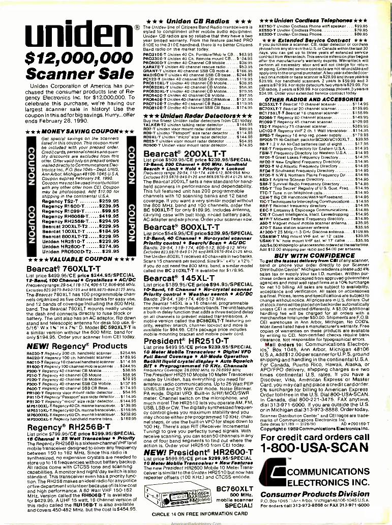
uniden® $12,000,000 Scanner Sale
Uniden Corporation of America has pur- chased the consumer products line of Re- gency Electronics Inc. for $12;000,000. To celebrate this purchase, we're having our largest scanner sale in history! Use the coupon in this ad for big savings. Hurry...offer ends February 28, 1990.
** *MONEYSAVING COUPON * ** Get special savings on the scanners listed in this coupon. This coupon must be included with your prepaid order. Credit cards, personal checks and quan- tity discounts are excluded from this offer. Offer valid only on prepaid orders mailed directly to Communications Elec- tronics Inc., P.O. Box 1045 - Dept. UNIS, Ann Arbor, Michigan 48106-1045 USA Coupon expires February 28, 1990. Coupon may not be used in conjunction with any other offer from CEI. Coupon may be photocopied. Add $12.00 for shipping in the continental U.S.A. Regency TS2 -T $259.95 Regency R1600 -T $239.95 Regency R1099 -T $99.95 Regency RH606B -T $419.95 Regency RH256B -T $294.95 Bearcat 200XLT -T2 $229.95 Bearcat 100XLT -T $184.95 Bearcat 800XLT -T2 $229.95 Uniden HR2510 -T $229.95 Uniden HR2600 -T $274.95 Uniden PRO500D-T2 $29.95
* ** *VALUABLE COUPON * * ** Bearcat/ 760XLT -T List price $499.95/CE price $244.95 /SPECIAL 12 -Band, 100 Channel Crystalless AC /DC Frequencyrange: 29-54,118-174,406-512,806-956 MHz Excludes 823.9875-849.0125 and 868.9875. 894.0125 MHz.
The Bearcat 76OXLT has 100 programmable chan- nels organized as five channel banks for easy use, and 12 bands of coverage including the 800 MHz. band. The Bearcat 76OXLT mounts neatly under the dash and connects directly to fuse block or battery. The unit also has an AC adaptor, flip down stand and telescopic antenna for desk top use. 6- 5/16" W x 1%" H x 7%" D. Model BC 590XLT -T is a similar version without the 800 MHz. band for only $194.95. Order your scanner from CEI today.
NEW! Regency® Products R4030 -T Regency 200 ch. handheld scanner .... $254.95 84020 -T Regency 100 ch. handheld scanner .... $189.95 84010 -T Regency 10 channel handheld scanner... $114.95 R1600 -T Regency 100 chañnel mobile scanner ... $244.95 P200 -T Regency 40 channel CB Mobile $38.95
$56.95 $79.95
$137.95 $174.95
o o C
o z
o C o z
o C
o z
n o C
o z
P210 -T Regency 40 channel CB Mobile P220 -T Regency 40 channel CB Mobile P300 -T Regency 40 channel SSB CB Mobile P400 -T Regency 40 channel SSB CB Base PRI00 -T Regency visor mount radar detector $54.95 PR110-T Regency "Passport" size radar detector ... $114.95 PR120 -T Regency "micro" size radar detector.... $144.95 MP5100XL- TRegency40 Ch. manne transceiver... $139.95 M P551 OXL-T Regency 60 Ch. marine transceiver... $159.95 MP6000XL -T Regency60 Ch. manne transceiver... 5209.95 MP2000XL.T Regency handheld manne trans $189.95
Regency® RH256B -T List price $799.95/CE price 5299.95 /SPECIAL 10 Channel 25 Watt Transceiver Priority The Regency RH256B is a sixteen-channel VHF land mobile transceiver designed to cover any frequency between 150 to 162 MHz. Since this radio is synthesized, no expensive crystals are needed to store up to 16 frequencies without battery backup. All radios come with CTCSS tone and scanning capabilities. A monitor and night/day switch is also standard. This transceiver even has a priority func- tion. The RH256 makes an ideal radiofor any police or fire department volunteer because of its low cost and high performance. A 60 Watt VHF 150 -162 MHz. version called the RH808B -T is available for $429.95. A UHF 15 watt, 16 channel version of this radio called the RU158B -T is also available and covers 450 -482 MHz. but the cost is $454.95.
* ** Uniden CB Radios * ** The Uniden line of Citizens Band Radio transceivers is styled to compliment other mobile audio equipment. Uniden CB radios are so reliable that they have a two year limited warranty. From the feature packed PRO 810E to the 310E handheld, there is no better Citizens Band radio on the market today. PRO310E -T Uniden 40 Ch. Portable /Mobile CB... $83.95 PRO330E -T Uniden 40 Ch. Remote mount CB... $104.95 PRO500D -T Uniden 40 Channel CB Mobile $38.95 KARATE -T Uniden 40 channel rescue radio $53.95 GRANT -T Uniden 40 channel SSB CB mobile .... $166.95 MADISON -T Uniden 40 channel SSB CB base ... $244.95 PC122 -T Uniden 40 channel SSB CB mobile $119.95 PRO51 OXL-T Uniden 40 channel CB Mobile $38.95 PRO52OXL -T Uniden 40 channel CB Mobile $56.95 PRO53OXL -T Uniden 40 channel CB Mobile $79.95 PRO540E -T Uniden 40 channel CB Mobile $97.95 PRO640E -T Uniden 40 channel SSB CB Mobile ... $137.95 PRO710E -T Uniden 40 channel CB Base 5119.95 PRO810E -T Uniden 40 channel SSB CB Base ... $174.95
* * * Uniden Radar Detectors*** Buy the finest Uniden radar detectors from CEI today. TALKER -T2 Uniden talking radar detector $144.95 RD7 -T Uniden visor mount radar detector $99.95 RD9 -T Uniden "Passport" size radar detector .... $114.95 RD9XL -T Uniden "micro" size radar detector $144.95 R025 -T Uniden visor mount radar detector $54.95 RD500 -T Uniden visor mount radar detector $74.95
Bearcat® 200XLT-T List price $509.95/CE price $239.95 /SPECIAL 12 -Band, 200 Channel 800 MHz. Handheld Search Limit Hold Priority Lockout Frequency range: 29 -54, 118 -174, 406 -512, 806.958 MHz Excludes 823.9875- 849.0125 and 868.9875. 894.0125 MHz. The Bearcat 200XLT sets a new standard for hand- held scanners in performance and dependability. This full featured unit has 200 programmable channels with 10 scanning banks and 12 band coverage. If you want a very similar model without the 800 MHz. band and 100 channels, order the BC 100XLT T for only $189.95. Includes antenna, carrying case with belt loop, ni -cad battery pack, AC adapter and earphone. Order your scanner now.
Bearcat® 800XLT -T List price$549.95 /CE price8239.95 /SPECIAL 12 -Band, 40 Channel No- crystal scanner Priority control Search/Sean AC /DC Bands: 29 -54, 118 -174, 406 -512, 806 -912 MHz Excludes 823.9875- 849.0125 and 868.9875- 894.0125 MHz. The Uniden 800XLT receives 40 channels in two banks. Scans 15 channels per second. Size9' /." x4'/2" x 121/2." If you do not need the 800 MHz. band, a similar model called the BC 21OXLT -T is available for $178.95.
Bearcat® 145XL -T List price $189.95/CE price $94.95 /SPECIAL 10 -Band, 10 Chanel No- crystal scanner Priority control Weather search AC /DC Bands: 29 -64, 136-174, 406 -512 MHz The Bearcat 145XL is a 16 channel, programmable scanner covering ten frequency bands. The unit features a built -in delay function that adds a three second delay on all channels to prevent missed transmissions. A mobile version called the BC560XLT -T featuring pri- ority, weather search, channel lockout and more is available for $94.95. CEI's package price includes mobile mounting bracket and mobile power cord.
President® H R251 O -T List price $499.95/CE price $239.95 /SPECIAL 10 Meter Mobile Transceiver Digital VFO Full Band Coverage Ail -Mode Operation Backlit liquid crystal display Auto Squelch RIT Preprogrammed 10 KHz. Channels Frequency Coverage: 28.0000 MHz to 29.6999 MHz.
The President HR2510 Mobile 10 Meter Transceiver made by Uniden, has everything you need for amateur radio communications. Up to 25 Watt PEP USB/LSB and 25 Watt CW mode. Noise Blanker. PA mode. Digital VFO. Built -in S /RF /MOD /SWR meter. Channel switch on the microphone, and much more! The HR2510 lets you operate AM, FM, USB, LSB or CW. The digitally synthesized frequen- cy control gives you maximum stability,and you may choose either pre -programmed 10 KHz. chan- nel steps, or use the built -in VFO for steps down to 100 Hz. There's also RIT (Receiver Incremental Tuning) to give you perfectly tuned signals. With receive scanning, you can scan 50 channels in any one of four band segments to find out where the action is. Order your HR2510 from CEI today.
NEW! President® HR2600 -T List price $599.95/CE price 5299.95 /SPECIAL I0 Meter Mobile Transceiver New Features The new President HR2600 Mobile 10 Meter Trans- ceiver is similar to the Uniden HR2510 but now has repeater offsets (100 KHz.) and CTCSS encode.
BC760XLT 800 MHz.
mobile scanner SPECIAL!
CIRCLE 14 ON FREE INFORMATION CARD
** *Uniden Cordless Telephones * ** XE750 -T Uniden Cordless Phone witfl speaker .... $99.95 XE550 -T Uniden Cordless Phone $79.95 XE300 -T Uniden Cordless Phone $69.95
* ** Extended Semler) Contract * ** If you purchase a scanner, CB, radar detector or cordless phone from any store in the U.S. or Canada within the last 30 days, you can get up to three years of extended service contract from Warrantech. This service extension plan begins after the manufacturer's warranty expires. Warrantech will perform all necessary labor and will not charge for return shipping. Extended service contracts are not refundable and apply only to the original purchaser. A two year extended con- tract on a mobile or base scanner is $29.99 and three years is $39.99. For handheld scanners, 2 years is $59.99 and 3 years is$79.99. For radar detectors, two years is 529.99. For CB radios, 2 years is $39.99. For cordless phones, 3 years is $34.99. Order your extended service contract today.
OTHER RADIOS AND ACCESSORIES BC55XLT -T Bearcat 10 channel scanner $114.95 BC7OXLT -T Bearcat 20 channel scanner $159.95 BC175XLT -T Bearcat 16 channel scanner $156.95 R2086 -T Regency 60 channel scanner $149.95 R1099 -T Regency 45 channel scanner $109.95 132 -T Regency 75 channel scanner $269.95 UC102 -T Regency VHF 2 ch. 1 Watt transceiver. $1 14.95 BPS5-T Regency 16 amp reg. power supply $179.95 BP205 -T1 Ni-Cad batt pack for BC200 /BC100XLT...$39.95 138 -T 1.2 V AA Ni -Cad batteries (set of eight) $17.95 FBE -T Frequency Directory for Eastern U.S.A $14.95 FBW -T Frequency Directory for Western USA $14.95 RFD1-T Great Lakes Frequency Directory $14.95 RFD2 -T New England Frequency Directory $14.95 RFD3 -T Mid Atlantic Frequency Directory $14.95 RFD4 -T Southeast Frequency Directory $14.95 RFD5 -T N.W 8 Northern Plains Frequency Dir $14.95 ASD-T Airplane Scanner Directory $14.95 SRF -T Survival Radio Frequency Directory $14.95 TSG-T "Top Secret" Registry of U.S. Govt. Freq $14.95 TTC -T Tune in on telephone calls $14.95 CBH-T Big CB HandbooI/AM /FM /Freeband $14.95 TIC-TTechniques for Intercepting Communications $14.95 RRF -T Railroad frequency directory $14.95 EEC -T Embassy 8 Espionage Communications $14.95 CIE -T Covert Intelligence, Elect. Eavesdropping $14.95 MFF -T Midwest Federal Frequency directory $14.95 A60-T Magnet mount mobile scanner antenna $35.95 A70-T Base station scanner antenna $35.95 Al 300-T 25 MHz. -1.3 GHz Diacone antenna $109.95 USAMM -T Mag mount VHF ant. w/ 12' cable $39.95 USAK -T y." hole mount VHF ant. w/ 17 cable $35.95 Add $4.00 shipping for all accessories ordered at the same time. Add $12.00 shipping per radio and $4.00 per antenna.
BUY WITH CONFIDENCE To get the fastest delivery from CBI of any scanner, send or phone your order directly to our Scanner Distribution Center" Michigan residents please add4% sales tax or supply your tax I.D. number. Written pur- chase orders are accepted from approved government agencies and most well rated firma at a 10% surcharge for net 10 billing. All sales are subject to availability, acceptance and verification. All sales on accessories are final. Prices, terms and specifications are subject to change without notice. All pricesare in U.S. dollars. Out of stock items wil l be placed on backorder automatically unless CEI is instructed differently. A $5.00 additional handling fee will be charged for all orders with a merchandise total under$50.00. Shipments are F.O.B. CEI warehouse in Ann Arbor, Michigan. No COD's. Most items listed have a manufacturer's warranty. Free copies of warranties on these products are available by writing to CEI. Non -certified checks require bank clearance. Not responsible for typographical errors.
Mail orders to: Communications Electron- ics" Box 1045, Ann Arbor, Michigan 48106 U.S.A. Add $12.00 per scan nerfor U.P.S. ground shipping and handling in the continental U.S.A. For Canada, Puerto Rico, Hawaii, Alaska, or APO /FPO delivery, shipping charges are two times continental U.S. rates. If you have a Discover, Visa, American Express or Master Card, you may call and place a credit card order. 5% surcharge for billing to American Express. Order toll -free in the U.S. Dial 800-USA-SCAN. In Canada, dial 800 -221 -3475. FAX anytime, dial 313- 971 -6000. If you are outside the U.S. or in Michigan dial 313-973-8888. Order today. Scanner Distribution Center" and CEI logos are trade- marks of Communications Electronics Inc. Sale dates 9/1/89 - 2/28/90 AD *090189 -T
Copyrights, 1989 Communications Electronlcsinc.
For credit card orders call 1-800-USA-SCAN
MCOMMUNICATIONS ELECTRONICS INC.
Consumer Products Division P.O. Box 1045 O Ann Arbor, Michigan 48106 -1045 U.S.A. For orders call 313. 973.8888 or FAX 313-971-6000
AmericanRadioHistory.Com
Related Documents