This item was submitted to Loughborough's Research Repository by the author. Items in Figshare are protected by copyright, with all rights reserved, unless otherwise indicated. Innovation in construction techniques for tall buildings Innovation in construction techniques for tall buildings PLEASE CITE THE PUBLISHED VERSION PUBLISHER © Ian R. Skelton PUBLISHER STATEMENT This work is made available according to the conditions of the Creative Commons Attribution-NonCommercial- NoDerivatives 4.0 International (CC BY-NC-ND 4.0) licence. Full details of this licence are available at: https://creativecommons.org/licenses/by-nc-nd/4.0/ LICENCE CC BY-NC-ND 4.0 REPOSITORY RECORD Skelton, Ian R.. 2019. “Innovation in Construction Techniques for Tall Buildings”. figshare. https://hdl.handle.net/2134/19637.

Welcome message from author
This document is posted to help you gain knowledge. Please leave a comment to let me know what you think about it! Share it to your friends and learn new things together.
Transcript

This item was submitted to Loughborough's Research Repository by the author. Items in Figshare are protected by copyright, with all rights reserved, unless otherwise indicated.
Innovation in construction techniques for tall buildingsInnovation in construction techniques for tall buildings
PLEASE CITE THE PUBLISHED VERSION
PUBLISHER
© Ian R. Skelton
PUBLISHER STATEMENT
This work is made available according to the conditions of the Creative Commons Attribution-NonCommercial-NoDerivatives 4.0 International (CC BY-NC-ND 4.0) licence. Full details of this licence are available at:https://creativecommons.org/licenses/by-nc-nd/4.0/
LICENCE
CC BY-NC-ND 4.0
REPOSITORY RECORD
Skelton, Ian R.. 2019. “Innovation in Construction Techniques for Tall Buildings”. figshare.https://hdl.handle.net/2134/19637.

Innovation in Construction Techniques
for Tall Buildings – Aerodynamic Advancement of the Lifting Wing
Ian R Skelton
Lend Lease
Regents Place
London
NW1 3BF
Centre for Innovative and Collaborative
Construction Engineering
Department of Civil & Building Engineering
Loughborough University
Loughborough
Leicestershire, LE11 3TU

Certificate of Originality
Thesis Access Conditions and Deposit Agreement
Students should consult the guidance notes on the electronic thesis deposit and the access conditions in the
University’s Code of Practice on Research Degree Programmes
Author Ian Robert Skelton
Title Innovation in Construction Techniques for Tall Buildings – Aerodynamic Advancement of the Lifting Wing
I, Ian Robert Skelton of Thames Bank House, Park Avenue, Sunnymeads, Wraysbury, Windsor, “the Depositor”,
would like to deposit ‘Innovation in Construction Techniques for Tall Buildings’, hereafter referred to as the
“Work”, once it has successfully been examined in Loughborough University Institutional Repository
Status of access OPEN
Moratorium Period 2 years, ending December / 2016
Status of access approved by (CAPITALS):……………………………………………………………………
Supervisor (Signature)………………………………………………...…………………………………...
School of……………………………………………………………………...…………………………………
Author's Declaration I confirm the following:
CERTIFICATE OF ORIGINALITY
This is to certify that I am responsible for the work submitted in this thesis, that the original work is my own
except as specified in acknowledgements or in footnotes, and that neither the thesis nor the original work therein
has been submitted to this or any other institution for a degree
NON-EXCLUSIVE RIGHTS
The licence rights granted to Loughborough University Institutional Repository through this agreement are
entirely non-exclusive and royalty free. I am free to publish the Work in its present version or future versions
elsewhere. I agree that Loughborough University Institutional Repository administrators or any third party with
whom Loughborough University Institutional Repository has an agreement to do so may, without changing
content, convert the Work to any medium or format for the purpose of future preservation and accessibility.
DEPOSIT IN LOUGHBOROUGH UNIVERSITY INSTITUTIONAL REPOSITORY
I understand that open access work deposited in Loughborough University Institutional Repository will be
accessible to a wide variety of people and institutions - including automated agents - via the World Wide Web.
An electronic copy of my thesis may also be included in the British Library Electronic Theses On-line System
(EThOS).
I understand that once the Work is deposited, a citation to the Work will always remain visible. Removal of the
Work can be made after discussion with Loughborough University Institutional Repository, who shall make best
efforts to ensure removal of the Work from any third party with whom Loughborough University Institutional
Repository has an agreement. Restricted or Confidential access material will not be available on the World Wide
Web until the moratorium period has expired.

- That I am the author of the Work and have the authority to make this agreement and to hereby give
Loughborough University Institutional Repository administrators the right to make available the Work in the
way described above.
- That I have exercised reasonable care to ensure that the Work is original, and does not to the best of my
knowledge break any UK law or infringe any third party’s copyright or other Intellectual Property Right. I have
read the University’s guidance on third party copyright material in theses.
- The administrators of Loughborough University Institutional Repository do not hold any obligation to take
legal action on behalf of the Depositor, or other rights holders, in the event of breach of Intellectual Property
Rights, or any other right, in the material deposited.
The statement below shall apply to ALL copies:
This copy has been supplied on the understanding that it is copyright material and that no quotation from
the thesis may be published without proper acknowledgement.
Restricted/confidential work: All access and any copying shall be strictly subject to written permission from
the University Dean of School and any external sponsor, if any.
Author's Signature Date 28/5/14
User’s declaration: for signature during any Moratorium period (Not Open work):
I undertake to uphold the above conditions:
Date Name (CAPITALS) Signature Address

INNOVATION IN CONSTRUCTION TECHNIQUES FOR
TALL BUILDINGS – AERODYNAMIC ADVANCEMENT OF THE LIFTING WING
By
Ian R Skelton
A dissertation thesis submitted in partial fulfilment of the requirements for the award of the
degree Doctor of Engineering (EngD), at Loughborough University
May 2014
© by Ian R Skelton 2014
Lend Lease
Regents Place
London
NW1 3BF
Centre for Innovative and Collaborative Construction
Engineering
Department of Civil & Building Engineering
Loughborough University
Loughborough
Leicestershire, LE11 3TU

Acknowledgements
1
ACKNOWLEDGEMENTS
All my thanks to:
The diligent and undiminishing Jacqui Glass, Peter Demian, Dino Bouchlaghem, and Chimay Anumba who
supervised, directed and encouraged me along my lengthy research path;
The Aeronautical Professors, Engineers and Technicians of Loughborough University who helped model and
test the ‘Wing’;
Lend Lease (Bovis Lend Lease (Bovis)) for sticking with the programme through the high peaks and deep
troughs of the fickle construction market;
The ever-enthusiastic tall building specialists who travel the world chasing the tallest towers and complete
carefully considered responses to probing questionnaires and interviews.
Finally, special thanks to:
Ellie for her unwavering support throughout;
Max and Sam Skelton for providing brief periods of quiet and calm, allowing me to focus the attention, whilst
they grew from babies to toddlers to ‘big boys’;
Mum and Dad for the gentle prods and pokes along the way;
Grandpa Bob for his searching weekly questions like “haven’t you finished it yet E?” – Finally, Yes!
i

Abstract
ii
ABSTRACT
Tall Buildings Are Here To Stay - Historical Précis
The skyline of many ‘world cities’ are defined and punctuated by tall buildings. The drivers for such dominant
skylines range from land scarcity and social needs; high real estate values; commercial opportunity and corporate
demand, through to metropolitan signposting. This fascination with tall buildings started with the patrician
families who created the 11th Century skyline of San Gimignano by building seventy tower-houses (some up to
50m tall) as symbols of their wealth and power. This was most famously followed in the late 19th Century with
the Manhattan skyline, then Dubai building the world’s highest building, then China building some eighty tall
buildings completed in the last 5 years, then UK building Europe’s highest tower, the Shard and finally back to
Dubai, planning a kilometre tall tower, potentially realising Ludwig Mies van der Rohe’s ‘Impossible Dream’ of
the 1920’s and Frank Lloyd Wright’s 1956 ‘Mile High Illinois’. This ambition to build higher and higher
continues to challenge the Architects, Engineers and Builders of tall buildings and is expected to continue into
the future. The tall building format is clearly here to stay.
“Building Skyscrapers is the nearest peace-time equivalent to war. The analogy to war is the strife
against the elements…..Foundations buried deep in the earth alongside existing towering skyscrapers.
Water, quicksand and clay block our path to the bedrock. Traffic rumbles in the crowded highways
above us and the subways, gas, water-mains, electricity and delicate signal communications demand
that they not be disturbed lest the nerve system of a great city be deranged. The service of supply of
materials in peace-time warfare, the logistics of building; these men are the soldiers of a great creative
effort”
Col. W. A. Starrett, Skyscrapers and Men Who Built Them (1928). New York NY.
Evolution of Tall Buildings and Current Changes
The development of increasingly sophisticated construction materials and technologies has fuelled the evolution
of the modern skyscraper throughout the 20th and early 21st century. The resulting structures have reflected this
evolution in the advancement in height, but the overall form of virtually every tall building until fifteen years ago
adhered to one of only two design philosophies: the simple extrusion footprint or staggered setback, dictated by
planning designed to abate the growing darkness on streets below. In pioneering cities around the world, the
majority of designs for tall buildings now reject those conventional limitations with structures that tower, taper,
tilt and twist, previously thought impossible to build.
These innovative tall buildings bring unprecedented challenges to the developers, designers and not least, the
builders. Technological obstacles must be overcome. Cutting edge design must be converted into a built reality.
Safety of its builders and occupants must be ensured. The substantial risk of cost and programme overruns must
be minimised. All must be overcome to ensure success of the tall building. As the builders of the Empire State

Abstract
iii
Building, Starrett Brothers and Eken noted “between the completion of the plans and the opening of the doors, it
is the builder’s show”.
This EngD research and the resulting thesis explores the challenges that face the builder of tall, increasingly
irregularly shaped structures and determines a new solution to one of the most critical issues. This is seen as
fundamental to the commercial viability and sustainability of the new breed of tall buildings. To date there has
been very little research in this building arena, in contrast to the voluminous research on the urban planning,
structural, architectural and services design of tall buildings. This EngD partially redresses that imbalance by
presenting three research stages driven by three key objectives:
Objective One
‘Undertake a Literature Review and profile the UK Tall Building market for value, growth and demand
sub-sectors’ - From early 2006 up to the freeze induced by the worlds faltering financial markets during
the first quarter of 2008, Britain experienced demand for tall buildings of an unprecedented high level -
in London alone, ten tall buildings have started, or were due to start on site between first quarter of
2007 to the fourth quarter 2008. This is directly comparable in size to America’s Manhattan Island
skyscraper boom of the 1920’s. A number of important results revealed during this first stage of
research were: firstly, investigation into the evolution of the UK tall building construction and
determination of the reasons behind its growth at previously unprecedented rates; secondly, creation of
a definition of the UK tall building and comparison to the international tall building stage; thirdly,
analysis of the differing types of demand and definition of these sub sectors of UK tall building market;
finally, the calculation of the size and value of this specialist construction market, forecasting its growth
potential and model it against the ‘Skyscraper Index’;
Objective Two
‘Capture and analyse International survey information from Tall Building experts to determine key
‘wins’ & ‘losses’ on tall building projects’ - This research stage captured the global state-of-the-art of
the tall building industry. This was achieved by: firstly, designing a questionnaire which tackled the
most pressing issues of the tall building process; secondly, targeting the questionnaire at the most active
tall building professionals around the globe; and thirdly, gaining an 80% response rate, giving a great
insight to the differences of opinion from Dubai to London, China to Chicago, Sydney to Vietnam. The
research was conducted in five key areas: the current state-of-the-art of the international tall building
industry; the build process of a tall building; the tall building principal contractor key features/issues;
‘wins’ and ‘losses’ inherent with past tall building projects; and new techniques from overseas and
other industries that could be adapted to the construction industry. The analysed results lead to some
surprising conclusions and offered a clearly signposted way ahead for innovative construction of tall
buildings, headlining on ‘expertise of project staff’ and ‘the negative effect of wind’ as two of the most
common, critical issues;
ii

Abstract
iv
Objective Three
‘Develop an innovative solution to one of the most critical and common key tall building project losses’
– In this final stage, innovative research was undertaken into the most common critical issue raised by
the global tall building experts in the second stage of the research: that of wind and its profound
negative effect on the construction critical path of the tall building. Theoretical and aerodynamic
research was undertaken, culminating in model making and wind tunnel testing of the ‘Lifting Wing’, a
unique design allowing building material to be lifted by tower cranes in higher and more unstable wind
conditions.
The Thesis concludes by outlining a number of recommendations for adoption by the tall building industry and
suggestions for future research.
KEY WORDS
Tall Building, Skyscraper, High-Rise, Construction, Building, Innovation, Aerodynamic Engineering, Lifting
Wing, Wind, Tower Crane.

Abstract
v
Figure 0-1 Frank Lloyd Wright’s 1956 The Mile High Illinois
vi

Used Acronyms And Abbreviations
vi
USED ACRONYMS AND ABBREVIATIONS
AAE Aeronautical and Automotive Engineering
BLL Bovis Lend Lease
CAD Computer Aided Design
CAM Computer Aided Manufacturing
CICE Centre for Innovative and Collaborative Engineering
CDrag Coefficient of Drag
CLift Coefficient of Lift
CM Construction Management
CNC Computer Numerical Control
CSideforce Coefficient of Side Force
EngD Engineering Doctorate
GFC Global Financial Crisis
GMP Guaranteed Maximum Price
HS&E Health, Safety & Environment
ICE Institute of Civil Engineers
IS Ian Skelton
LL Lend Lease
LU Loughborough University
MDPI Multi-Disciplinary Digital Publishing Institute
NTC Net Trade Cost
PC Principal Contractor
PM Project Management
R&D Research and Development
RE Research Engineer
Re Reynolds Number
USP Unique Selling Point

Table of Contents
vii
TABLE OF CONTENTS
Acknowledgements .................................................................................................................... i
Abstract ................................................................................................................................. …ii
Key Words ............................................................................................................................... iv
Used Acronyms And Abbreviations ...................................................................................... vi
Table of Contents ................................................................................................................... vii
List of Figures And Tables ..................................................................................................... ix
List of Papers ............................................................................................................................ x
1 Background to the Research ........................................................................................ 1 1.1 The General Subject Domain .......................................................................................... 2 1.2 The Industrial Sponsor .................................................................................................... 3 1.3 The Context of the Research ........................................................................................... 3 1.4 Thesis Structure .............................................................................................................. 4
1.5 Summary .......................................................................................................................... 5
2 Overarching Aim and Objectives ................................................................................ 6 2.1 Detailed Objectives ......................................................................................................... 7
2.2 Justification of the Research ........................................................................................... 7 2.3 Novelty of the Research .................................................................................................. 8
2.4 Summary ......................................................................................................................... 8
3 Adopted Methodology .................................................................................................. 9 3.1 Methodology Overview………………………………………………………………...9
3.2 Methodological Considerations.....................................................................................10
3.3 Methods Used…………………………………………………………………………10
3.3.1 Stage 1...........................................................................................................................11
3.3.2 Stage 2...........................................................................................................................13
3.4 Summary.......................................................................................................................14
4 The Research Undertaken .......................................................................................... 15 4.1 Introduction ................................................................................................................... 15 4.2 Research Order .............................................................................................................. 15 4.3 Taught Element ............................................................................................................. 15 4.4 Literature Review .......................................................................................................... 17 4.5 Focus Group and Questionnaire Design ....................................................................... 27
4.6 Innovation for Single Critical ‘Loss’ ............................................................................ 36 4.7 Summary ....................................................................................................................... 65
5 Findings & Implications ............................................................................................. 67 5.1 The Key Findings of the Research ................................................................................ 67 5.2 Contribution to Existing Theory and Practice .............................................................. 70
5.3 Implications/Impact on the Sponsor ............................................................................. 71
5.4 Implications/Impact on Wider Industry ........................................................................ 72
5.5 Recommendations for Industry/Further Research ........................................................ 73 5.6 Critical Evaluation of the Research .............................................................................. 74 5.7 Summary ....................................................................................................................... 75

Table of Contents
viii
6 References .................................................................................................................... 92
Appendix A Paper 1 ............................................................................................................ 97
Appendix B Paper 2 .......................................................................................................... 109
Appendix C Paper 3 .......................................................................................................... 116
Appendix D Business Market Review ............................................................................. 139
Appendix E Business Case For The Lifting Wing ........................................................ .170
Appendix F CTBUH Questionnaire .............................................................................. .185

List of Figures ANd Tables
ix
LIST OF FIGURES AND TABLES
Figure 0-1 Frank Lloyd Wright’s 1956 The Mile High Illinois...............................................................v
Figure 2-1. The Aim, Objectives and Resultant Published Papers of the EngD.....................................6
Figure 3-1 Research Stages, Objectives and Methodologies.................................................................9
Figure 4-1. Future 150m+ Skyline of London?.....................................................................................18
Figure 4-2. Or is 300m+ the Future for London?..................................................................................19
Figure 4-3. Past Future of Tall? (Wakisaka 1995).................................................................................22
Figure 4-4. The Air Ships of Old – Inspiration for the Lifting Wing....................................................37
Figure 4-5. Flat Section Separated Flow (Kermode 2012)....................................................................42
Figure 4-6. Cylinder Section Separated Flow (Kermode 2012)............................................................42
Figure 4-7. Aerofoil Separated Flow (Kermode 2012)..........................................................................43
Figure 4-8. Wind Force coefficients on the Lifting Wing.....................................................................45
Figure 4-9. Loughborough University Aeronautical and Automotive Engineering Open Circuit
Wind Tunnel Isometric……………………………………………..………………..………………...51
Figure 4-10. LU AAE Wind Tunnel Bell-mouth & Exhaust…………..………….................………...52
Figure 4-11. Six-Component Balance below Tunnel Working Section…………..…………………...52
Figure 4-12. Scale Model Wing Mounted on the Working Balance of the Tunnel................................54
Figure 4-13. Scale Model ‘Brick’ Mounted on the Working Balance of the Tunnel.............................55
Figure 4-14a. Brick Re V's Cd................................................................................................................56
Figure 4-14b. Wing Re V's Cd...............................................................................................................57
Figure 4-15. LU Wind Tunnel Aerotech Balance OGI. Recording Lift, Pitch, Drag, Side, Yaw,
Roll & Wind Speed (at 30m/s)...............................................................................................................58
Figure 4-16a Wing and Brick Yaw Angles Vs CDrag for 30m/s and 40m/s………..………………...58
Figure 4-16b. Wing and Brick Yaw Angles Vs CLift for 30m/s and 40m/s…………..………..……..59
Figure 4-17. Brick nose at -25 degrees, 40m/s.......................................................................................61
Figure 4-18 Wing tail at -25 degrees, 40m/s..........................................................................................61
Figure 4-19a. Wing Suspended for Dynamic Test.................................................................................63
Figure 4-19b. Wing with Internal Load Plates Inside.............................................................................63
Figure 5-20. USS Macon over New York City, Summer 1933..............................................................77

List of Papers
x
LIST OF PAPERS
The following papers, included in the appendices, have been produced in partial fulfilment of the award
requirements of the Engineering Doctorate during the course of the research.
PAPER 1 (SEE APPENDIX A)
Skelton, I. Demian, P. Bouchlaghem, D. (2009). Britain’s Tall Building Boom: Now Bust? Proceedings
of the Institution of Civil Engineers Structures and Buildings 162. June 2009, Issue SB3, Pages 161–
168. doi: 10.1680/stbu.2009.162.3.161
PAPER 2 (SEE APPENDIX B)
Skelton, I. Bouchlaghem, D. Demian, P. Anumba C. (2009). The State-of-the-Art of Building Tall.
Challenges, Opportunities and Solutions in Structural Engineering and Construction. ISEC-5,
September 2009, University of Nevada, Las Vegas, USA. Taylor & Francis Group, London. ISBN 978-
0-415-56809-8.
PAPER 3 (SEE APPENDIX C)
Skelton, I. Demian, P. Glass, J. Bouchlaghem, D. Anumba C. (2014). The Lifting Wing In Constructing
Tall Buildings – Aerodynamic Testing. Proceedings of the MDPI AG Buildings & Engineering Journal.
Basel, Switzerland. ISBN 2075-5309. Published 28th May 2014. Buildings 2014, 245-265;
doi:10.3390/buildings4020245.
List of Papers
1
1 BACKGROUND TO THE RESEARCH
1.1 THE GENERAL SUBJECT DOMAIN
This chapter provides an introduction to the thesis and EngD research which explores the challenges that face the
builder of tall, increasingly irregularly shaped structures and determines an innovative solution to one of the
most critical challenges in six key phases of work. It sets out the context of the Industry and the Industrial
Sponsor, Lend Lease (formally Bovis Lend Lease, preceded by Bovis).
A total of three papers have been published (the first of which was published as a 5000 word version for the ICE
Structures and Building Journal, also as an abridged 3000 word version for the ICE Civil Engineer Journal, as
well as a revised version for the US, published by ISEC). Paper 1 and 2 were also presented at an ISEC
conference, all in fulfilment of the EngD. These are discussed later in this Chapter and are enclosed in Appendix
A, B & C.
The research formed six significant work phases:
The first significant work phase was the completion of the five MSc-level modules stipulated by Loughborough
University in fulfilment of the formal learning requirements for the Engineering Doctorate. These were carefully
selected to align with the needs of the RE in filling knowledge gaps and giving specialist skills needed to achieve
the objectives of the EngD. Three modules were successfully completed at Loughborough University, the first
CVP008 ‘Research, Innovation and Communication’ in March 2007, the second CVP034 ‘Management and
Professional Development 1’ in August 2007 and the third CV035 ‘Management and Professional Development
2’ in the second quarter of 2008. Simultaneously, an MBA module ‘Entrepreneurial and Business Creativity’ and
an MSc module ‘Entrepreneurial Strategy’ were both taken during the third and fourth quarters of 2007 at
University of Surrey. The final award of ‘Distinction’ for both modules was made by the University of Surrey in
the first quarter 2008. In December 2008, following the completion of these formal learning modules,
Loughborough University awarded a Post Graduate Certificate with Distinction in Engineering Innovation and
Management;
The second significant work phase was undertaking the Literature Review, which captured an over-view of the
high rise building market in the UK, calculated its size, and captured its key issues, perceived problems and
market growth prospects. A report was generated from the Literature Review and issued to the sponsor company
BLL UK Executive Management Team in May 2007. This economic-biased report was stipulated by the BLL
EMT as the first output required from the EngD, and its resultant information was planned to inform the business
of the scale and growth prospects for the UK tall building market. It was subsequently used to determine the
forthcoming BLL UK Three Year Business Plan. The findings of this report were also utilised by the BLL office
in Milan and Lend Lease Ventures in Sydney during 2008 to inform business decisions regarding entering the
tall building market. The literature review also investigated the current state of innovation in the construction

2
industry and established the ‘current cutting edge’ for tall building construction and contextualised this against
the historic influence of new methods of construction on architectural design.
The third significant work phase was the research undertaken for the writing of ‘Britain’s Tall Building Boom –
Now Bust?’ a five thousand word technical paper published by the Institute of Civil Engineers for their
Structures and Building Journal (ISI Impact Factor of 2) in June 2009. The ICE also published a three thousand
word abridged version of this paper for their July 2009 publication of Civil Engineer (ISI Impact Factor of 1.5);
The fourth significant work phase was the research undertaken for the paper ‘The State of the Art of Building
Tall’. This five thousand word paper was published and presented at the 5th International Structural Engineering
& Construction (ISEC) Conference at the University of Nevada, Las Vegas in September 2009, along with a four
thousand five hundred word version of ‘Britain’s Tall Building Boom – Now Bust?’ paper, revised for the
American audience. The research for this paper commenced with targeted structured interviews, held with four
major tall building related companies. These interviews gave shape, direction and focus to the designing of the
‘State of the Art of Building Tall’ questionnaire. The questionnaire was tailored to capture the most pressing
issues of the tall building process, then issued through a variety of methods, targeting the most active specialist
tall building professionals around the globe. The dominant method of targeting the specialist professionals was
to hand-issue to a selection of attendees at the Council of Tall Buildings and Urban Habitat (CTBUH) 8th World
Congress, held in March 2008 in Dubai, along with hand-issue at the New Civil Engineer’s ‘Engineering Tall
Buildings September 2008 Conference’, held in London. An 80% response rate was obtained from these
conferences. The results and feedback was collated and analysed to form the basis of this third paper;
The fifth significant work phase was a distinct analysis of the most common and highest ranked tall building
‘losses’ determined from the results and feedback given during ‘The State-of-the-Art of Building Tall’ research.
This led to the focus of the final phase of research on the most critical of these ‘losses’ – the critical path effect
of wind on construction programme.
The sixth and final significant work phase developed an innovative concept aimed at positively affecting the
critical path delay of wind on the construction programme for tall buildings, called the ‘Lifting Wing’. A scale
model was been constructed and successfully tested at Loughborough University’s Aeronautical and Automotive
Engineering (AAE) wind tunnel during the first half of 2013. This series of wind tunnel tests generated results
allowing detailed analysis to be undertaken and conclusion to be drawn, forming the final paper ‘Lifting Wing –
Aerodynamic Testing’. This was accepted for publication by the Editorial Panel of Buildings & Engineering
Journal and published in May 2014.
As ever, the RE’s motivation, enthusiasm and interest in the topic remain ‘high’!

3
1.2 THE INDUSTRIAL SPONSOR
Tall Buildings – Bovis Lend Lease Desires & Aims for the EngD
‘With our ever increasing involvement in major high rise projects across the global business, and the
ever more challenging designs of these buildings in terms of height, form and complexity, the need for
collaboration and knowledge sharing in this specialist field has never been greater’
(John Spanswick, former Bovis Lend Lease Chairman and Global Sponsor of High Rise Community of
Practice. September 2006.)
Lend Lease (previously registered and widely-known as Bovis until 2001, then as Bovis Lend Lease until 2012)
is an internationally recognised leader in the construction of innovative and challenging projects. This has
included tall buildings around the globe. The successful delivery of these projects demands the spanning of
divisional, functional and geographical boundaries in order to distil and corral internal high rise experience,
bringing innovation, ideas and insights into the way we manage the planning and construction of tall buildings.
This EngD research was initiated in late 2006 and was aimed at exploring the challenges that face the builder of
tall, increasingly irregularly shaped structures to determine a new or improved technique, system or method to
address one of the critical challenges. The intention was that this would assist Lend Lease regain their position as
innovative leaders in the UK construction market by developing a unique selling point (USP) to be utilised when
bidding tall building projects and allow the RE to establish a centre of excellence for high rise construction
techniques, improving the way Lend Lease compete in the UK high-rise business environment.
At inception, the aim of this EngD was closely aligned with Bovis’s organisational strategy and planned as a
USP and key differentiator in winning tall building work. Its outputs were planned to be a valuable resource in
developing best practice solutions to meeting future tall building challenges in the UK. This was unfortunately
superseded by the global recession from 2007 until early 2013, when demand for tall buildings reduced or
disappeared in many countries. The only tall buildings to be constructed during this period were those that had
already started or had been committed to financially. Fortunately, this started to change during mid-2013 as tall
building projects began once more to make financial sense. Lend Lease was again keen to pursue tall building
projects and so the original EngD aim re-aligned with post global financial crisis (GFC) corporate strategy.
1.3 THE CONTEXT OF THE RESEARCH
Bovis Lend Lease Innovation and Performance Department ran an internal national competition in 2006 to find
the most suitable candidate to undertake an Engineering Doctorate (EngD) on any proposed topic that was
deemed most valuable to Bovis Lend Lease. In August 2006 the RE won this competition with a proposal to
undertake the Doctorate on the topic of innovation in the construction of tall buildings. On award, the RE
transferred from UK Operations Division to the Innovation and Performance Division. The EngD commenced

4
and progressed ahead of programme until the RE’s transfer from BLL’s Innovation and Performance Division
into the Construction Services Division of UK South in January 2008, when EngD progress faltered due to
bidding work commitments. This move was instigated to enable the RE to assist in winning new work for the
company and it had several benefits to the work of the EngD, including gaining more tall building knowledge
through heavy involvement with two significant tall building bids (Project Centurion, a 46 storey steel framed
commercial building in the City of London for JP Morgan with a construction cost of circa £400million and
Newington Butts, a 44 storey concrete framed residential tower in Southwark designed by Richard Rodgers for a
private Client, construction cost circa £80 million) plus several substantial, high density residential development
bids (Project Blue at Chelsea Barracks, construction cost circa £1.6 billion and Penthouses A, B & C at One
Hyde Park, Knightsbridge, total construction cost circa £90 million) during 2008 and early 2009. This bidding
work substantially increased the RE’s knowledge of the each type of construction project, and gave valuable
experience of undertaking ‘hook time analysis’ of a steel framed tall building and a concrete framed tall
building. This analysis utilised the Bill of Quantities, structural, architectural and services drawings of the two
tall buildings to determine all construction materials to be lifted by tower crane or hoist (for smaller materials)
and the time taken to lift, land and return to the material pick up point, which ultimately helps build the
Construction Programme for a tall building. This analysis also allowed the RE to determine a list of the most
commonly lifted materials and their physical dimensions, utilised later in the research for developing the
innovative solution named the Lifting Wing. Valuable experience was also gained in cutting edge competitive
bidding in a rapidly shrinking market. The demands of this bid work resulted in a delay of six months to the
EngD programme. In September 2009, the RE led a bid for a £35million Penthouse C Project for the Prime
Minister and Foreign Minister of Qatar at One Hyde Park, Knightsbridge. This prestigious project was
subsequently awarded and commenced on site in November 2009, with the RE as Project Director. The project
had a planned completion of 23rd
July 2012, however several substantial design changes resulted in the
completion being extended to 16th
November 2012. During this period, research on the EngD slowed and was
eventually formally placed on hold via a Leave of Absence granted by the University. The Penthouse Project
was successfully completed on programme, allowing the RE to re-register at LU and recommence research in
January 2013, with a planned completion date of the EngD of May 2014.
1.4 THESIS STRUCTURE
This Thesis is structured into five remaining Chapters:
Chapter Two, ‘Overarching Aims and Objectives’ presents the CICE and Sponsoring Company demands for the
EngD and how these were incorporated into the main aim, the detailed objectives and how this correlates to the
published papers. It also clarifies the justification for the research.
Chapter Three, ‘Adopted Methodology’ presents the qualitative and quantitative research methodology
selected. It includes the Literature Review, in-depth focused research on critical issues, focus group work, survey
and scientific experimentation methods, each used at a different stage of research in fulfilment of the overall
EngD requirements.

5
Chapter Four ‘Research Undertaken’ presents in chronological order the research completed by the RE,
commencing with the taught element, the Literature Review, the research into international tall building project
critical issues, the focusing on one common and critical issue (that of the effect of wind on the build programme
of the tall building), the development of the innovative concept to solve this problem and the experimental
analysis undertaken to prove its effectiveness.
Chapter Five, ‘Findings and Implications’ presents the main findings and conclusions drawn from the research.
It discusses the impact on the Sponsor Company and for the wider industry. A critical evaluation of the study is
discussed and areas for further study are proposed.
1.5 SUMMARY
This Chapter introduced the Industrial Sponsor and its desires for the EngD in the context of the Tall Building
Industry. It outlined the resulting EngD research and presented the thesis subject, which is the exploration of the
challenges that face the builder of tall, increasingly irregularly shaped structures and determination of an
innovative solution to one of the most critical and common challenges. The research work phases and resulting
published papers were presented and the structure of the thesis itself was clarified.

6
2 OVERARCHING AIM AND OBJECTIVES
Loughborough University CICE defines a key aspect of the Engineering Doctorate as the solution of one or more
significant and challenging problem with the industry (CICE 2010). The RE and Sponsor Company set the
primary aim as the exploration of the challenges that face the builder of tall, increasingly irregularly shaped
structures to determine the key ‘wins’ and ‘losses’ and ultimately determine a new or improved technique,
system or method to address one of these critical challenges. As research progressed on the EngD, the ranking of
key tall building project losses was undertaken, the most critical of these being determined as the effect of wind
on the critical path of a tall building, ultimately leading to the invention of a potential solution. In order to
achieve the primary aim, a total of three key objectives and five sub-objectives were set to break the research
down into meaningful work stages. These are detailed in Section 2.1. The aim and the objectives are detailed in
Figure 2-1 below, including reference to the resulting published papers.
Figure 2-1. The Aim, Objectives and Resultant Published Papers of the EngD
PRIMARY AIM Investigate the challenges that face the builder of tall, increasingly irregularly shaped structures to determine the key
‘wins’ and ‘losses’ and ultimately determine a new or improved technique, system or method to address one of these
critical challenges
OBJECTIVE 1
Undertake a Literature Review
and profile the UK Tall Building
market for value, growth and
demand sub-sectors
OBJECTIVE 2
Capture and analyse
International survey information
from Tall Building experts to
determine key ‘wins’ & ‘losses’
on tall building projects.
OBJECTIVE 3
Develop an innovative solution
to one of the most critical and
common key Tall Building
Project ‘loss’
PAPER 1
‘Britain’s tall building boom:
now bust?’ Proceedings of the
Institution of Civil Engineers
Structures and Buildings
PAPER 2
‘The State-of-the-art of Building
Tall.’ Challenges, Opportunities
and Solutions in Structural
Engineering and Construction.
ISEC-5
PAPER 3
‘The Lifting Wing In
Construction Tall Buildings –
Aerodynamic Testing.’
Engineering and Building
Journal
ENGINEERING DOCTORATE THESIS Innovation in Construction Techniques for Tall Buildings

7
2.1 DETAILED OBJECTIVES
To achieve the primary aim of the EngD, The 3 main objectives and 5 sub-objectives were set to corral and
direct the research though the EngD period. These were:
1. Undertake a literature review of tall building construction industry and profile the UK market. Identify
key issues, components and problems inherent in the discipline of building tall buildings.
1.1 Determine the construction value and forecast the potential growth of the UK tall building market.
Determine the demand sub-sectors for tall buildings and the drivers for each sub-sector. Determine the
threats and opportunities for the market.
2. Capture and analyse International survey information from Tall Building experts to determine key
‘wins’ & ‘losses’ on tall building projects.
2.1 Design and develop a questionnaire tool to capture key tall building information from expert
international tall building project personnel. Apply the tool to capture international high rise project
experience from specifically identified leading international tall building specialist, including a cross
section of developers, architects, engineers and builders.
2.2 Distil the international survey information to highlight key ‘wins’ & ‘losses’ on tall building
projects.
2.3 Investigate outstanding project wins. Assess the contributing factors and the environment. Consider
adaptations required to allow these international wins to ‘fit’ into UK market.
2.4 Isolate recurring construction ‘loss’ underlying root causes. Analyse emerging patterns to highlight
recurring weaknesses in the approach to high rise construction.
3. Develop an innovative construction technique to overcome one of the root causes of the construction
‘losses’ and that responds to the latest design demands.
2.2 JUSTIFICATION OF THE RESEARCH
The construction industry has long had a reputation of lacking innovation, being slow to develop and risk
averse. This was famously reinforced by the findings of The Latham Report ‘Constructing the Team
(Latham, 1994) and followed up by The Construction Task Force headed by Sir J Egan ‘Rethinking
Construction’ HMSO (Egan, 1998). Perhaps unsurprisingly, the industry has been traditionally slow to react
to these findings, however in more recent years the most proactive main contractors and sub-contractors
have become keener to improve their image by investing in innovation and development as they see this as a
unique selling point (USP) in the very competitive post-recession market place. BLL recognised this and
saw the EngD output as a potential USP or key differentiator for one of their targeted growing specialist
markets, the tall building.
This EngD research was initiated in late 2006 and was aimed at exploring the UK tall building market and
the challenges that face the builder of tall, increasingly irregularly shaped structures to ultimately determine

8
a new or improved technique, system or method to address one of the critical challenges. The intention was
that research would assist BLL regain their position as innovative leaders in the UK construction market by
developing a USP to be utilised when bidding high-profile tall building projects and allow the writer to
establish a centre of excellence for high rise construction techniques in the UK.
BLL had previously won and built numerous notable tall buildings across the world including Petronas
Towers in Kuala Lumpa, Trump Towers in New York, Aurora Place in Sydney and Bishopsgate Tower and
early works on 122 Leadenhall in London. However, BLL were replaced on Leadenhall following the
project being placed on hold due to the financial recession and subsequently did not win a tall building
tender for several years. Additionally, many of the key personnel directly involved with these tall building
projects had left the company. Once BLL commissioned the RE to commence the EngD, an internal report
was requested to be presented to the UK Board determining the tall building market size, value and growth
potential. This report showed that from early 2005 Britain was experiencing a demand for tall buildings of
an unprecedented high level. In London, five tall buildings were due to start on site between first quarter
2005 to the first quarter of 2006 and more tall buildings were being worked on by architectural practices in
London than ever before. BLL decided they wanted a share of this market and recognised that they needed
to regain the cutting-edge tall building knowledge and a USP to win such projects. The EngD was a direct
result of this desire.
2.3 NOVELTY OF THE RESEARCH
This EngD research explores the challenges that face the builder of tall, increasingly irregularly shaped
structures and aims to determine a new solution to a key project loss, which is deemed fundamental to the
commercial viability and sustainability of tall buildings. The information gathered and analysed for this
EngD has in many instances been determined first-hand from first principles, as sector specific information
for the tall building construction market does not readily exist. Data was compiled and extrapolated from
standard construction market sector information, then filtered against a number of criteria to provide
meaningful tall building results. The Literature Review showed that to date there had been very little
research in this building arena, in contrast to the voluminous research on the design of tall buildings. This
EngD aims to redress that imbalance.
2.4 SUMMARY
This Chapter clarified the primary aim of the EngD, distilled from the key requirements of the CICE and
BLL. From this, three key objectives and numerous sub-objectives were established to fulfil the
requirements of the EngD. The research justification was also presented.

9
3 ADOPTED METHDOLOGY
This chapter provides an overview of the considerations recognised in the selection of the methodology, the
individual methodologies adopted in each stage of the EngD research and the ability of each to achieve the
research objectives presented in Chapter 2.
3.1 METHODOLOGY OVERVIEW
The EngD research methodology was broken down into two main stages involving several distinct
methodologies. Multiple research techniques or procedures were actively used to gather and analyse the
specialist data needed for the Thesis. This ‘mixed research method’ has been recognised as having a beneficial
contribution to the findings due to reduced or eliminated disadvantages of each individual approach, whilst
maximising advantages (Fellows & Liu, 2003). The mixed research method is described below:
Stage 1: International best practice tall building research (Background Theory) leading to the key
‘wins’ & ‘losses’ on tall building projects (Focal Theory);
Stage 2: Research focusing on a single key ‘loss’ and developing a theoretical solution (Data Theory)
then proving the theoretical solution with innovative research (New Contribution).
STAGE 1 STAGE 2
OBJECTIVE 1 OBJECTIVE 2 OBJECTIVE 3 OBJECTIVE 3
Figure 3-1. Research Stages, Objectives and Methodologies.
Stage one research was initiated with Background Theory, undertaken to provide an understanding of the current
high rise construction market. This commenced by undertaking a Literature Review of the tall building industry,
academically recognised as the most effective method to determine the status of the chosen research field by
providing the ‘foundation’ of knowledge. The Literature Review was undertaken by reviewing previous
published research work highlighting common themes, arguments, gaps in current understanding and ultimately
isolating areas warranting further research. The findings from this Literature Review were then utilised to
generate the Market Report, primarily to satisfy the initial requirement of the Sponsoring Company. The report
was designed to help convey an understanding the market sector, allowing the company to decide if it was
deemed a commercially desirable sector and help determine what measures would need to be taken for the
sponsor company to re-enter this market. The stage one research then progressed on to Focal Theory. This
methodology allowed the cataloguing of best practice techniques or ‘wins’ both within and external to BLL,
BACKGROUND THEORY
Literature Review and
Market Report
FOCAL THEORY
Key Tall Building ‘Wins’
and ‘Losses’
DATA THEORY
Focus on a solution to
one Common and Critical
‘Loss’ with theoretical
research
NEW CONTRIBUTION
Test and Prove the
Innovation

10
allowing comparisons across the globe to be drawn. This would highlight common critical ‘loss’ areas that lack a
cutting-edge or state-of-the-art approach.
Stage one research acted as the springboard for stage two, which commenced with Data Theory assisting in
focusing the research toward one common and critical tall building ‘loss’. This in turn led to the creation of an
innovative solution, or concept. The final methodological approach was New Contribution, the proving of the
concept through a blend of established academic theory and innovative testing and experimentation.
3.2 METHODOLOGICAL CONSIDERATIONS
The CICE and the sponsoring company (BLL) requirements were at the forefront of determining the
methodology of the research. The CICE state ‘a fundamental element of a successful EngD is the contribution to
a solution of a significant and challenging engineering problem’. Similarly BLL required the EngD to ‘span
divisional, functional and geographical boundaries in order to distil and corral internal high rise experience,
bringing innovation, ideas and insights into the way we manage the planning and construction of tall buildings’
(Spanswick, J. BLL Chairman). These two key requirements led to the methodology strategy utilised in the
delivery of the EngD research. Flexibility and dynamism also had to be built into the research methodology to
react to dramatic cyclical changes to the marketplace resulting in changing desires from the Sponsor Company,
particularly prevalent through the GFC of 2008 – 2013.
3.3 METHODS USED
A mix of quantitative and qualitative research methods were planned to be used during the research process to
maximise benefits and minimise the disadvantages of each individual approach. This ‘mixed methods’ approach
reduces or eliminates recognised disadvantages with each distinct approach whilst maintaining their advantages
(Fellows & Liu, 2003). Within the four research theories described in the following section, five distinct
methodologies were utilised at various stages of the research. These included: Action Research (collaborative
problem solving); Focus Group (group discussion based interviews determining the jointly understood
conclusion); Survey (systematic data collection from a defined population); Statistical Analysis (interpretation of
this survey data) and Experimental Research (experiments undertaken in controlled environment with
controllable variables); all recognised research styles (Fellows & Lui, 2003).

11
3.3.1 STAGE 1
BACKGROUND THEORY
Literature Review and Market Report
The methodology adopted for the Background Theory was an extensive literature review of tall building
academic research and of the UK tall building market. This provided the foundation of knowledge for the EngD
research to build upon and allowed the refinement of the objectives and methodology adopted. It produced new
data allowing the Net Trade Cost of the tall building market to be calculated and captured the ‘first draft’ of the
market’s key issues, perceived problems and market growth prospects. It also showed gaps in previous research
and highlighted areas for further research. This report was issued to the Bovis Lend Lease UK Executive
Management Team in May 2007. The findings of this report have subsequently been utilised by the BLL office
in Milan and Lend Lease Ventures in Sydney during 2008 to position the company for future tall building work.
This work satisfied Objective 1, to ‘undertake a Literature Review and profile the UK Tall Building market for
value, growth and demand sub-sectors’.
FOCAL THEORY
Key Tall Building ‘Wins’ and ‘Losses’
This initial literature review was then focused on several key areas of research and supplemented in depth during
the Focal Theory stage of the research. This was undertaken in two steps:
Firstly, the data gained during the literature review was investigated in more detail for the seventeen key findings
determined as of critical importance to the UK Tall Building industry. This formed the basis for the first paper
‘Britain’s Tall Building Boom – Now Bust?’ published by the Institute of Civil Engineers for their Structures
and Building Journal in June 2009 (Appendix A). An abstract for the paper follows:
‘From early 2006 up to the freeze induced by the worlds faltering financial markets during the first quarter of 2008, Britain
experienced demand for tall buildings of an unprecedented high level – in London alone, ten tall buildings have started, or
are due to start on site between first quarter 2007 to fourth quarter 2008. This is directly comparable in size to America’s
Manhattan Island skyscraper boom of the 1920’s. The objectives of this paper are: Firstly, to investigate the evolution of the
UK tall building construction and determine the reasons behind its growth at previously unprecedented rates; Secondly, to
create a definition of the UK tall building and compare it to the international tall building stage; Thirdly, to analyse the
differing types of demand and define these sub sectors of UK tall building market; Finally, to calculate the size and value of
this specialist construction market, forecast its growth potential and model it against the Skyscraper Index.’
The seventeen findings of the research for this paper were distilled down to nine key results for the first
publication and are discussed in Chapter 5 ‘Findings and Implications’, Section 5.

12
Secondly, Focus Group and Survey methods were utilised to gain the data for the second paper ‘The State of the
Art of Building Tall’, published and presented at the 5th International Structural Engineering & Construction
(ISEC) Conference at the University of Nevada, Las Vegas in September 2009.
The research for this second paper involved understanding the specific issues associated with building a tall
building and the ‘wins’ and ‘losses’ experienced during the process. This commenced with Focus Group semi-
structured interviews, held with four tall building project construction Company Directors, one of which was
internal to BLL. Two sets of these interviews gave shape, direction and clarity to the designing of the ‘State of
the Art of Building Tall’ questionnaire. This led to the next stage of research utilising Survey methodology. A
questionnaire was tailored from feedback gained during the Focus Group to clearly capture the most pressing
issues of the tall building process and allow them to be rated and ranked. It was issued to a defined population of
the most active tall building professionals around the globe, as well as being hand-issued to targeted specialist
professionals attending the Council of Tall Buildings and Urban Habitat (CTBUH) 8th World Congress, held in
March 2008 in Dubai and the New Civil Engineer’s ‘Engineering Tall Buildings September 2008 Conference’,
held in London. The results gained from the questionnaire responses were analysed and formed the basis for the
second published paper ‘The State of the Art of Building Tall’ (Appendix B). An abstract follows:
‘Following on from the first published paper titled 'Tall Building Boom - Now Bust?' which concluded that Britain's demand
for tall buildings of an unprecedented high level, directly comparable in size to Americas Manhattan Island skyscraper boom
of the 1920’s, but was ultimately heading for a recession, this second paper determines the global state of the art of building
tall. This has been achieved by firstly designing a questionnaire which tackles the most pressing issues of the tall
building process, secondly, targeting the questionnaire at the most active tall building professionals around the globe and
thirdly, gaining an 80 % response rate, giving a great insight to the differences of opinion from Dubai to London, China to
Chicago, Sydney to Vietnam. In summary, this paper investigates five key areas: the current state-of-the-art of the
international tall building industry; the build process of a tall building; the tall building principal contractor key
features/issues; lastly, wins and losses inherent with past tall building projects; new techniques from overseas and other
industries.
The analysed results lead to some surprising conclusions and offer a clearly signposted way ahead for innovative
construction of tall buildings.’
The work undertaken to this point satisfied Objective 2, to ‘capture and analyse international survey information
from tall building experts to determine key ‘wins’ & ‘losses’ on tall building projects’.

13
3.3.2 STAGE 2
DATA THEORY
Focus on a solution to one Common and Critical ‘Loss’ with theoretical research
This involved isolating the construction ‘losses’ reported in the above work, analysing the underlying / root
causes and determining the most important loss upon which to concentrate efforts to mitigate or solve. A
clearly recurring theme of the analysed questionnaire responses returned from the Dubai and London
conferences was that wind had a critical impact on construction risk and the ability to deliver surety in
programme and therefore cost of a tall building. This lead to a focus on investigating ways to mitigate the
effect of wind on the most critical single element of building a tall building - the tower crane. Two ideas
were conceived, both aimed at increasing the safety and speed of construction of tall buildings. They were
christened the ‘Mag Spanner’ and the ‘Lifting Wing’. They were both aimed at satisfying the diametrically
opposed needs of time, cost, quality and safety on tall building projects. The mag spanner was quickly
developed and has been introduced on many BLL steel frame projects with a significant reduction in the
number of dropped bolts, washers and spanners. The Lifting Wing was deemed the more important of the
two innovations having the most profound potential benefit and therefore became the focus for the final
stage of research.
NEW CONTRIBUTION
Test and Prove the Innovation
This stage of the research was the development of one innovative construction technique to overcome a root
cause of a key construction ‘loss’. Of the two innovative ideas conceived during the research, the concept
with the biggest potential impact on speed of construction of tall buildings was determined to be the Lifting
Wing. This was demonstrated to have the potential to reduce the tall building industry accepted norm of
40% down-time for a tower crane, thereby saving time on the critical path of the tall building construction
programme and hence, substantial costs. Experimental methodology was employed to test the concept. This
initially involved theoretical aerodynamic development, followed by scale model building and finally
obtaining quantitative data from wind tunnel testing and qualitative date from flow visualisation and
dynamic testing.
The results gained from the experimental analysis formed the basis for the final published paper ‘The Lifting
Wing In Constructing Tall Buildings – Aerodynamic Testing’, published in May 2014 in MDPI AG
Buildings & Engineering Journal (Appendix C). An abstract follows:
This paper builds on previous research by the authors which determined the global state-of-the-art of constructing tall buildings
by surveying the most active specialist tall building professionals around the globe. That research identified the effect of wind on
tower cranes as a highly ranked, common critical issue in tall building construction. The research reported here presents a design

14
for a ‘Lifting Wing’, a uniquely designed shroud which potentially allows the lifting of building materials by a tower crane in
higher and more unstable wind conditions, thereby reducing delay on the programmed critical path of a tall building. Wind tunnel
tests were undertaken to compare the aerodynamic performance of a scale model of a typical ‘brick shaped’ construction load
(replicating a load profile most commonly lifted via a tower crane) against the aerodynamic performance of the scale model of the
Lifting Wing in a range of wind conditions. The data indicates that the Lifting Wing improves the aerodynamic performance by a
factor of 50%.
This work satisfied Objective 3, to ‘develop an innovative solution to one of the most critical and common key
Tall Building Project ‘loss”.
3.4 SUMMARY
This chapter detailed the methodology adopted in each stage of the research, structured to achieve each of the
research objectives discussed in Chapter 2 whilst being flexible and dynamic to accommodate changing demands
from the sponsoring company. A mix of quantitative and qualitative research methods were used as the research
progressed to maximise benefits of each. Literature Review, In-depth Focused Research on critical issues, Focus
Group, Survey and Experimentation methods were all utilised in fulfilment of the EngD requirements.
15
4 THE RESEARCH UNDERTAKEN
4.1 INTRODUCTION
This chapter describes in chronological order, the original research work completed to fulfil the aims and
objectives of the EngD, as described in Chapter 2 and in accordance with the research methodology clarified in
Chapter 3. Each activity is then described in detail and the relevance to the EngD research is explained.
Reference to the published papers (Appendix A-C) is made where relevant.
4.2 RESEARCH ORDER
The order in which the research was carried out was dictated by the set objectives, with the exception of the
Taught Element which was a CICE mandatory requirement to be completed in the second year of the EngD.
Firstly, the Literature Review of tall building construction was undertaken and the UK tall building market
was profiled. Investigation into the future of tall buildings generated a working list of areas for latter stage
EngD research.
Secondly, a questionnaire tool was designed and developed to capture key information on the international
tall building process. This was used to capture key information from specifically identified leading
international tall building professionals over a market cross section of developers, architects, engineers and
builders. This information was analysed to highlight key ‘wins’ & ‘losses’ on international tall building
projects. The outstanding project wins and recurring construction ‘losses’ were analysed to highlight
recurring weaknesses in the approach to high rise construction and possible areas for improvement.
Thirdly, one of the most common and critical construction ‘losses’ was selected as the focus for
development of the innovative construction solution. This idea was developed by critiquing it against
established theory. The resulting refined design was then modelled and wind tunnel tested to validate the
innovation.
The detail of the research undertaken is presented below.
4.3 TAUGHT ELEMENT
The successful completion of a maximum of six MSc-level modules totalling 60 Credits was stipulated by
Loughborough University in fulfilment of the formal learning requirements for the Engineering Doctorate. These
were to be completed within the first two years of the EngD and were carefully selected by the RE, where not
mandatory courses, to align with the needs of the RE, filling knowledge gaps and giving specialist skills needed
to achieve the objectives of the EngD. The sixty Credits were achieve with five selected modules.
Three modules were successfully completed at Loughborough University, the first CVP008 ‘Research,
Innovation and Communication’ in March 2007, the second CVP034 ‘Management and Professional

16
Development 1’ in August 2007 and the third CV035 ‘Management and Professional Development 2’ in the
second quarter of 2008. Each was awarded ‘with Distinction’ by CICE, LU.
An MBA module ‘Entrepreneurial and Business Creativity’ and an MSc module ‘Entrepreneurial Strategy’ were
taken during the third and fourth quarters of 2007 at the University of Surrey. Each was awarded ‘with
Distinction’ by SU.
Additional skills training activities were undertaken during 2008. These topics selected for training fulfilled the
writer’s skill gap requirements and allowed fulfilment of the Management and Professional Development
Module CVP0035, the final stipulated LU taught element of the EngD:
1. Corporate Strategy
This involved a literary review of corporate management theory followed by a comparison to BLL
UK’s developing strategy. These findings were utilised to assist in the setting up of BLL Construction
Services strategy to deliver the LL Corporate Vision. It developed a clear understanding of corporate
strategy which assisted in translating the tall building specialist service vision developed through the
EngD, into a feasible proposition fitting within the latest BLL corporate strategy.
2. Business Plans and Objectives
This required improving skills in developing business objectives and business plan writing and has
allowed the progression of the tall building concept products currently being worked up through the
EngD toward a marketable product. This followed on from the corporate strategy skill in providing the
next step in the development of the tall building business strategy to a feasible business proposition. A
literature review of business plan writing and development theory was applied to the context of the UK
tall building market and allowed the feasibility of the tall building concept products to be investigated.
A business plan was written for future consideration by BLL.
3. Business Analysis (Strengths, Weaknesses, Opportunities and Threats, SWOT)
This involved a literature review of business analysis theory and application to the UK tall building
market for the innovative products under development in the EngD. Skills gained in undertaking this
research were used to clarifying how the proposed tall building innovative product would fit in the
market, which competitors exist, what they offer and the size of the market. This helped in proving the
business case for the product. The result were a picture of the market fit, the product strengths,
weaknesses, opportunities and threats, lending weight to proving the business case.
17
4. Proposals and Presentations
This involved reviewing the latest proposal and presentation techniques used in the construction
industry, determine what the best of LL’s competitors were doing in this field and determined the best
approach for the proposal document and presentations for a live project bid, running from May 2008 to
November 2008 (Project Blue, a £1.6 billion super-prime residential development for developers Candy
& Candy at Chelsea Barracks in London). The presentation and proposal techniques learned were also
utilised to internally promote the EngD primary output, the Lifting Wing concept. The development of
these skills was immediately required to help sustain the funding of the EngD which was under threat
through the initial UK economic recessionary period from 2008 – 2009. Internal promotion to the LL
Executive Management Team of the potential benefits of the EngD outputs assisted in retaining funding
to complete the EngD. These presentation skills were also used in fulfilling the RE’s Construction
Services role, bidding for tall buildings and ensuring submitted presentations were of an industry-
leading standard.
5. Implementation of Best Practice
This involved research into the specialised sub-sector of the tall building industry, the supplier of tower
cranes. The research determined the current UK best practices to maximise tower crane efficiency
whilst maintaining or improving safety on large projects. The factors influencing crane efficiency were
determined and methods to tackle these were investigated. The information gathered during this
research was been beneficial in proving the case for the Lifting Wing concept.
Additionally, skills were developed in the specialised area of scale model making and aerodynamics,
involving the theoretical analysis, design, building and wind testing of scale models at Loughborough
University’s Aeronautical and Automotive Engineering Department. This culminated in the wind tunnel
testing of the scale models of the Lifting Wing and Brick.
The final award of ‘Distinction’ for the MBA module ‘Entrepreneurial and Business Creativity’ and an MSc
module ‘Entrepreneurial Strategy’ was made by the University of Surrey in the first quarter 2008. This award
formally completed the requirements of the taught element of the Engineering Doctorate and in December 2008
Loughborough University awarded a Post Graduate Certificate with Distinction in Engineering Innovation and
Management.
4.4 LITERATURE REVIEW
This section details the research undertaken for the Literature Review. This was undertaken to fulfil Stage 1
Background Theory and Objective 1 of the EngD research, ‘Undertake a Literature Review and profile the UK
Tall Building market for value, growth and demand sub-sectors’. The Literature Review commenced at the

18
outset of the EngD, running in parallel with the Taught Element, but continued until May 2007. Once complete,
it provided a solid foundation of knowledge to commence Stage 2 of the research. A summary of the findings of
the report resulting from the Literature Review is included in this section of Chapter 4. The full report was issued
to the BLL Board in May 2007 and utilised to inform business strategy for the following 3 year business plan.
The full report is included in Appendix D. All results and conclusions were correct at that time.
UK Tall Building Market Sector Report - An Overview of the Market and its Forecast to 2012
(May 2007).
Figure 4-1. Future 150m+ Skyline of London?
Report Introduction
This report was the result of first-hand, first principles research into the tall building market sector of the UK
construction industry. The objectives of this report were:
To analyse the size of this specialist market and determine the potential value of this market to
Bovis Lend Lease;
To analyse the reasons why the local market is currently growing at an unprecedented rate,
understand the types of demand and forecast its growth potential;
To explain the UK tall building in a Global tall building setting;
To determine the nature and structure of the tall building industry, the business models, risk
profile and its supply chain characteristics;
To consider how these factors influence the delivery of tall buildings in London to achieve the
Mayor of London’s target, meet the unsatisfied demand of client's tall building requirements
and aspirations;

19
To determine Bovis Lend Lease’s current market position, review what the competitors are
doing differently, outline market opportunities and provide new data on which a Bovis Lend
Lease tall building strategy can be based;
To investigate typical cost and revenue generators for tall buildings;
To provide innovative data worthy of future publication, in partial fulfillment of the
Engineering Doctorate requirements.
The report was in three parts:
Part I - Evolution of the UK Tall Building and the EngD. Key information from this report is utilised in
Paper 1 in Appendix A.
Part II - The Market Analysis. This sets out in detail the state-of-the-art of the UK Tall Building
market, calculates its current value at nearly £10 billion (Net Trade Cost) and forecasts its growth
prospects. Key information from this report is utilised in Paper 1 in Appendix A. The full report is
included in Appendix D.
Part III - The Future of Tall Buildings – This set out potential areas for further study during the
remaining research period of the EngD and sought BLL EMT direction on the what was deemed most
valuable or business relevant topics, assisting in the final selection of the area for further study.
Figure 4-2. Or is 300m+ the Future for London?
Executive Summary
This Market Analysis section of this report created a valuable and unique snap shot of the UK tall building
market. It included the current state and types of demand and supply, the market’s current value and its forecast
growth. The information contained in the analysis has been determined first-hand from first principles, as sector
specific information for the tall building construction market does not readily exist – it has to be compiled by
hand and extrapolated from current generic information for the standard market sectors, then filtered against a

20
number of criteria to provide meaningful tall building results. The full picture of the tall building market
presented in this analysis has been built up from a blend of new data generated during this research, live
information from industry recognised expert sources, plus theoretical and professional knowledge. This market
analysis concentrates on London as this forms almost 70% of the current UK tall building market, but also
considers all areas of the UK. This analysis made seventeen key findings:
The tall building form is not a passing design fad in the UK, it is here to stay and is currently
backed from the upper echelons of Central Government down to popular public opinion;
The UK tall building is defined in this report as a building of a height of twenty stories and
greater, due primarily to the change in building methodology required, but this only equates to
mid-rise on the international skyscraper stage;
Several new tall building clusters are being encouraged in London by Central Government, the
Mayor’s London Plan, CABE and by unsatisfied demand from the office, mixed use and
residential sectors;
The biggest threat to the continued growth of the London tall building market was considered
to be UNESCO’s pressure to stop tall buildings close to heritage sites of London and
Liverpool. This was fostered by Ruth Kelly’s (previous Secretary of the State at the
Department of Communities) anti–tall building stance, resulting in a Public Inquiry for 20
Fenchurch St. An anti-tall building precedent was expected to be set, but the Inquiry gave
approval, due mainly to the replacement Secretary of the State at the Department of
Communities (Hazel Blears) being more supportive of tall buildings.
There are four types of London tall buildings driven by four distinct areas of demand: the fat
office tower (18% of market demand); the skinny/iconic office tower (36%); the mixed use
tower (18%) and the residential tower (28%); as evidenced in the Tall Building Market Sector
Report, Appendix D;
The sum of these four markets means that the current high demand for tall buildings is
unprecedented – ten London tall buildings are due to start on site in 2007. This is directly
comparable in size to the Manhattan skyscraper boom of the 1920’s;
Capable tall building main contractors are now hardening their commercial stance by
becoming more selective, more risk averse and demanding a higher price. Tall building Clients
are increasingly having to use two stage or negotiated tenders to secure an experienced tall
building main contractor;
Bovis Lend Lease are consistently in the top three constructors of offices within the tall
building market sector, but do not rate in the residential sector of tall buildings;
Bovis Lend Lease’s biggest tall building competitors are Carillion, Skanska, Mace and Laing
O’Rourke (plus several residential tower builders). Each of these competitors has recognised
tall buildings as a target sector and have significant capital invested in specialist divisions to
bring in tall building work;

21
High barriers to entry minimise the likelihood of increasing overseas competition for the
construction of UK tall buildings;
London has thirty nine tall buildings potentially reaching site in the next three to five years, the
South East has four and the balance of the UK has fifteen. The total estimated net trade cost of
which is £9.957 Billion.
If BLL win only 5% of tall buildings in London and the South East (which equates to winning
just over two of the total forty seven projects proposed in this region) it would bring in
£47million (net trade cost) per annum for circa eight years (the average gestation and build
period of a UK tall building);
If BLL win 5% of all UK tall buildings it would bring in £62million (net trade cost) per annum
for circa eight years;
The average view of the independent economic forecasts considered for years 2007 to 20011 is
one of sustained growth for both the commercial and residential drivers of the tall building
market, with an increasing focus on mixed use (part commercial and part residential space)
towers as the most efficient way forward;
Costing models indicate twenty stories as the optimum height for tall buildings - there is an
exponential growth in cost from twenty to forty stories, which then levels out at the fiftieth
storey. This is discussed in the Tall Building Market Sector Report, Appendix D;
There are fifteen key cost generators and four revenue generators identified for a typical tall
building, again discussed in the Tall Building Market Sector Report, Appendix D;
Methods for increasing levels of prefabrication, mitigating the effect of wind on tall building
construction have been identified as warranting further study, as does speed of construction
versus cost and international best practice build methodology. These are possible areas for
further research during the EngD;
The facts behind these seventeen key findings are explained in more detail in the body of the market analysis -
Tall Building Market Sector Report in Appendix D.
In conclusion, this report found that the UK tall building construction market offers a considerable opportunity
for BLL immediately and over the next ten years. It is clear from the findings that a strategy needs to be
formulated to maximise on this market potential, whilst minimising operational risk. The report also clarifies that
BLL needs to capitalise on its in-house specialist skills and reputation as a builder of high quality tall buildings,
which should grow in stature once Bridgewater Place is handed over and as 201 Bishopsgate, 122 Leadenhall
and Newington Butts are successfully started on site. Capable tall building main contractors have all hardened
their stance in the UK market and tall building clients are increasingly using having to use two stage or
negotiated tenders to secure an experienced tall building contractor. The market was seen to bear a higher
contractor reward for the high risk of building tall.

22
Early ideas to be used in the formulation of a BLL tall building market strategy by the RE included methods to
gain an early position on tall building projects. These included: the utilisation and growth of in-house expertise
to give tall building advice earlier in the project life cycle (concept design stage); the potential benefit of the
procurement of, or partnering with, a tall building specialist service provider (such as tall building cranes,
logistics, high speed hoisting, etc.) again, aimed at gaining an early position on the project; plus the development
of an innovative concept to assist in the building of tall buildings. This last ideas was deemed the most
favourable outcome as it would provide a USP for the sponsoring company in a competitive market.
The Future of Tall Buildings – Potential Areas for Further Study
Figure 4-3. Past Future of Tall? (Wakisaka 1995)
Innovation in Tall Buildings
Tall buildings are recognised as a test-bed for innovations in the building industry. Following successful
application on a tall building, innovations then percolate down to the wider industry and other building types.
(Reina, 2009). One of the most successful tall building design innovations to date was unitised cladding (finished
glazing, frame & gaskets delivered to site as a prefabricated panel to be internally fixed), first developed for use
on American tall buildings, it is now widespread. Advantages include a safe, rapid and higher quality installation
of a cladding system available to commercial, residential and even industrial buildings worldwide. A more recent
example of tall building innovation is the pioneering use of robotic cleaning on the Mori Tower in Shanghai built
in 2005. One of the next big-impact design innovations yet to be built, but theoretically designed, could be the
use of multiple shuttle cars in a single lift shaft, the next progression on from recent vertical circulation

23
innovations such as sky lobbies, destination hall-call systems and double-decker lifts. This would have a
dramatic effect on the ability to build higher with fewer cores, substantially increasing net letable area of tall
buildings and therefore their commercial feasibility.
Innovation in the construction of tall buildings centres on the efficient management of a build process and the
achievement of speed safely. ‘The principle function of the builder of tall buildings is not to erect steel, brick or
concrete, but to provide a skilful, centralised management for coordinating the various trades, timing their
installations and synchronising their work according to a predetermined plan, a highly specialised function the
success of which depends on the personal skills and direction of its staff’ (Starrett, W. 1928). Following this
mantra of management of men, materials and money, Bill Starrett’s company, Starrett Brothers & Eken
successfully built the 86 storey Empire State building from foundations to occupancy in less than one year,
achieving one storey a day for a 10 day period. The planned durations for the key trades were: steel frame, 3.5
storeys per week; brick walls, a storey a day; stonework cladding, 2 stories a week. Trade workers peaked at
3500 on site (Willis C 1998). These build rates are the only record that the Empire State Building still holds
today (it was beaten in height in the 1970’s by New York’s World Trade Centre, then Chicago’s Sears Tower )
and is still an unattainable goal for the modern tall building some 70 years later.
Unlike the well-defined problems facing the design team, builders have to deal with external conditions beyond
their direct control such as the availability of raw materials, fluctuations in labour and material prices, and most
importantly, transportation of men and materials to meet programme. As William Starrett wrote in Skyscrapers
and the Men who Build Them (1928) ‘Building Skyscrapers is the nearest peace-time equivalent to war. It is
strife against the elements…The service of supply in peace-time warfare. The logistics of building and these men
are the soldiers of a great creative effort’. Logistics is therefore recognised as one of the key challenges to the
success of large building projects and is one of the oldest problems. The oldest known construction law is the
prohibition on daytime passage of carts bearing building material through the streets of Imperial Rome. Logistics
for the tall building was therefore warranted as an area for further study during the EngD.
Innovation in Construction
Historical studies show that new ideas are slow to be accepted in the construction industry. Traditionally a long
path is followed with the commonly recurring stages of; inception of the idea, testing of prototypes, trial use,
failure, gestation on the shelf, reinvention, retrial, success through construction of a seminal building, adoption,
misuse, rejection due to failure, introduction of legislation to control its use, gradual improvement of the material
or technique and finally, general acceptance (Strike 1991).
According to Leading Edge White Paper W/G1 on innovation (Leading Edge, 2006), the British Construction
Industry has appetite for incremental innovation as opposed to radical innovation (deemed to carry the highest
risk and highest potential returns). This taste for low risk product augmentation is due to market pressure for
quick profits, fast growth and share price dependency. This incremental innovation is also due to the marketplace
being mature and crowded. Within the building industry it is believed that differentiation can be achieved by
improving existing products, but competitor imitation can lead to cynical customers refusing to pay more. This
can then lead to discounting to increase sales volumes leading to low prices and little recovery prospects. This

24
has happened periodically in the construction market where companies have resorted to ‘buying’ competitive
tender projects to maintain turnover and profile in the market place. This means the market is ready for substitute
products or services that outmode the traditional market. The Lifting Wing innovation fulfils this definition.
The construction industry is traditionally adverse to high risk, break though innovation. The constraints inherent
in the construction industry in promoting this type of innovation are (Ettlie, 2006):
Clients or their procurement managers who are risk averse and stick to who they know;
No structured innovation process to manage risk, leading to expensive failures;
Need for complex formal analysis and metrics to prove investment potential of innovation;
Genuine complexity of market opportunities;
Companies fear of failure in tight job markets.
Overcoming these obstacles within BLL was determined as fundamental to the success of creating the tall
building USP required to raise BLL’s profile in the market.
The type of innovation sought by BLL then needed to be clarified. An established framework for innovation in
the construction industry is The Three Zones of Innovation (Leading Edge, 2006):
Zone 1 Basic Innovation: minor enhancement to an existing product or service giving short term returns
and saturated markets;
Zone 2 Relative Innovation: Adapting an existing product or service for new markets;
Zone 3 Concept Innovation: Creation of new product or service, break through business models or
value propositions. These have greater perceived risk and returns.
The focus of the latter stages of the EngD was agreed with BLL EMT to be on Zone 2 and 3 innovations. A
working list of ideas generated whilst undertaking the EngD research was used to understand the scope of
potential improvement areas during the Background Theory stage, until focus was turned on only one key idea
for further development during the Focus and Data Theory stages of research, thereby fulfilling the second set of
objectives detailed in Chapter 2.
Two other key areas researched in depth as part of a Literature Review but that did not ultimately get selected for
final stage innovative research were the prefabrication of tall buildings and improving safety in tall buildings
through minimising falls from height. The findings are discussed briefly below.
Can Tall Buildings be prefabricated?
Tall buildings are laboratories for design and construction. There will be problems associated with innovative
solutions - economies of scale cost implications of the small volume of production, learning curve productivity
issues etc. According to The Housing Forum (THF 2001), the advantages off-site fabrication for house building
include 50% reduction in handover defects, up to 50% saving on construction time and less weather and
vandalism risk to building and materials through earlier closure. Off-site fabrication requires substantially more

25
engineering to work effectively on tall buildings, but modular suppliers are actively researching this area and
have successfully built up to 14 stories to date.
(Forbes, 1996) argues the development of high strength concrete, which can be pumped 500m above ground is
the biggest factor against prefabrication. Its success has led to a trend across Australia for tall buildings
constructed in insitu concrete (transported as a liquid to its final position in a building and poured into steel,
plastic or plywood formwork). In the Middle East the Burj Dubai structure was built predominantly from high
strength, super plasticised, chilled concrete. However, there are huge potential benefits of prefabrication in
building tall due to the largely repetitive nature. This area was selected as a potential area to be investigated in
detail during the research as a potential innovation area, but was ultimately not taken forward due to the results
of the Focus and Data research stages indicating other areas having greater potential benefit.
Safety in Tall Buildings
Safety in the construction of tall buildings has always been a crucially important part of building, due in part to
the high profile level of interest that the construction process generates, plus the public’s daily visibility into the
works. Since 9/11, safety has become the focus of more disciplines in the tall building arena, but this effort has
focused predominantly on design changes for life safety systems and limited structural changes, rather than the
construction process itself.
One of the earliest records of investment in significant safety systems employed in the construction of tall
buildings is that of the Empire State Building. Contrary to popular belief, Starrett Brothers & Eken, the builder
of the Empire State Building were very concerned with safety and undertook numerous innovative measures to
increase mechanisation and ensure accidents were limited, even if it was believed at that time, some were
inevitable (Willis 1998). There were six deaths of construction workers on the Empire State and one death of a
member of the pubic, struck by falling timber, but Starrett & Co made substantial inroads towards a safer process
through mechanisation of construction.
The methods of erection have become substantially more mechanised since the 1930’s and the increasing use in
off-site production for elements of a tall building mean fewer onsite resources are required to construct a
building of similar scale today. A 3500 peak labour level for the Empire State Building would be circa 800 using
modern methods of construction. This reduced number would greatly assist in reducing the risk of accidents.
However, the main cause of accident on tall buildings is falls – either materials or man. This area was researched
in more detail as part of this study and culminated in the innovation named the ‘Mag Spanner’. Early Focus
Group interviews undertaken by the RE with the Project Directors of two BLL tall building projects had shown
that dropped bolts, nuts, washers and shims were the most frequent ‘near-miss’ safety occurrence on site. This
was caused when the structural frame installers working at height, commonly in adverse weather conditions,
dropped one of the fixing items (nut, washer, bolt or the spanner). To reduce this risk the RE developed a
magnetised socket-spanner which allowed the nut head and washer to be safely held in one socket head, whilst
the bolt was safely held within the other, released only when the elements had been securely bolted together.
Both spanners were securely attached to the steel fixer’s belt with a karabiner and an elasticated shock chord. In

26
trials on a BLL steel frame site, the Mag Spanners were well received by the steel frame contractor and their
operatives and as a result the number of items dropped from height over the period tested reduced significantly.
It has since been adopted on several UK BLL sites utilising steel structural frames.
Literature Review Summary
The extensive literature review achieved the following objectives that the sponsor company had defined as
desirable EngD outputs:
determine the size of this specialist market and determine the potential value of this market to
Bovis Lend Lease;
determine the reasons why the local market is currently growing at an unprecedented rate,
determine the types of demand and forecast the growth potential;
define the UK tall building in a Global tall building setting;
determine the nature and structure of the tall building industry, the business models, risk
profile and its supply chain characteristics;
consider how these factors influence the delivery of tall buildings in London to achieve the
Mayor of London’s target, meet the unsatisfied demand of client's tall building requirements
and aspirations;
determine Bovis Lend Lease’s current market position, review what the competitors are doing
differently, outline market opportunities and provide new data on which a Bovis Lend Lease
tall building strategy can be based;
determine typical cost and revenue generators for tall buildings;
Final object was to provide innovative data worthy of future publication. This was achieved as data from this
review was further researched and refined, then used as the basis for the first published paper ‘Britain’s tall
building boom: now bust?’ (Skelton, I. 2009).
Conclusion
This section of research concluded the EngD Objective 1 ‘Undertake a Literature Review and profile the UK
Tall Building market for value, growth and demand sub-sectors.

27
4.5 FOCUS GROUP AND QUESTIONNAIRE DESIGN
The research then moved on to fulfilling Stage 1, Objective 2, Focal Theory - establishing the key international
‘wins’ & ‘losses’ on tall building projects.
A working list of tall building project ‘key issues’ had been generated by the RE during the Literature Review
stage of the Doctorate. This long list was then distilled by conducting a series of semi-structured interviews with
a Focus Group of four tall building project construction Company Directors, one of which was internal to BLL.
This group were selected by the RE from the industry recognised major project experts and Directors of
construction companies who fulfilled the following three criteria:
The construction company (of which they were a Director) had completed in the last year, or were
currently building a tall building, as defined in the RE’s 1st published paper (Appendix A);
The construction company was in the Top 10 of the Construction News Contracts League,
Commercial Contractors (excl. Retail) Jan 2006 – Jan 2007 (Fig 7 Appendix D);
The construction company had current international major project experience.
Two sets of these interviews were held. The first was predominantly information gathering, whereby the original
RE-generated long-list of key issues was openly discussed in light of each Focus Group Director’s recent tall
building experience. Initially, this grew the list substantially, however after the RE analysed all issues raised in
this first round of interviews, it became clear there were five common topics that covered the majority of the
issues raised by the focus group. This rationalisation and refinement of the issues provided clarity and flow,
whilst preventing overlap and reiteration and were used to form the key sections of the questionnaire, designed
to allow an accurate snap-shot of the international tall building industry to be taken.
The RE conducted a literature review of questionnaire survey design theory, then utilised the refined tall building
key issues list (cross checked to ensure the Objective Two requirements were being met) to developing a draft
‘State-of-the-Art of Building Tall’ questionnaire. This draft questionnaire was reviewed with each of the Focus
Group Directors and refined further to ensure that the layout and questions were clear, unambiguous, whilst
capturing the critical information needed in a form that would allow rational scoring and meaningful analysis of
the results.
A Pilot Test was then conducted with ten tall building specialists, two from each of the five key disciplines to be
ultimately targeted in the formal questionnaire issue. These disciplines were: End User or Client; Investor or
Developer; Design Team member or Consultant; Specialist Contractor or Supplier; Main Contractor. Overall, the
Pilot Test was considered successful, with a few layout refinements made to make the questionnaire more
interesting, presentable and to enable the topics to flow. Relatively easy questions were presented first to engage
the respondent without over taxing them, followed by the more complex, open ended questions toward the end,
hence increasing the likely response rate. The pilot test also showed that a fuller and more considered response
was obtained if the questionnaire was issued personally by the RE and if the intent of the background research
(to which the questionnaire responses would form a key part) was given by the RE.

28
A cover letter was written that aimed to motivate respondents in the same way as the face-to-face discussion had
in the pilot test, whilst also reassuring respondent’s confidentiality. It also gave clear instructions on how to
complete the questionnaire and advised that the targeted 10 minute completion time was achieved in 50% of the
pilot test cases.
The final questionnaire was designed to have a mixture of quantitative and qualitative questions. The
quantitative sections were designed with a 5 point Likert method, ensuring the more difficult questions could be
answered with a ‘don’t know’ rather than missed out, giving a more analytical response. Scoring of the rated
questions utilised the System Usability Scale (Brooke, 1986). The qualitative questions were open ended, but
gave clear description, definition, and contextual framing for the responses required.
The five key areas captured in the survey were:
1. The current state-of-the-art of the international tall building industry, containing 11 rated questions;
2. The build process of a tall building, containing 3 rated questions and 1 question rating a list of 11 risk
elements;
3. The tall building principal contractor key features/issues, containing 8 rated questions;
4. ‘Wins’ and ‘Losses’ inherent with past tall building projects. This was an open ended question asking the
respondent to describe their personal experience of a memorable ‘win’ and ‘loss’ on a tall building project
they were involved in. These could be from any project phase from detailed design development, through
construction to completion, handover and occupancy of the building. ‘Wins’ were defined as things that
were done well on a tall building project that significantly contributed to the success of the construction
process. ‘Losses’ were defined as things that were not done well on a tall building project that negatively
contributed to the construction process.
5. New techniques from overseas and other industries, an open question asking the respondent to describe any
ideas, new techniques or practices they have seen that could be adopted in the construction process of a tall
building project. These ideas could be from overseas construction methods, other industry practices or just
areas where the traditional building approach seems outdated and in need of a fresh approach. They could
cover any project phase from detailed design development, through construction to completion, handover
and occupancy of the building;
The final section asked for respondent’s details, including their tall building project name, professional
discipline and contact details, to enable analysis of the results gained by discipline, geographical location
and the ability for the RE to follow up on tardy responses.
The final questionnaire issued at the CTBUH Tall Building Conference in Dubai is enclosed in Appendix F.
Lightly amended versions of this questionnaire were issued at the other tall building conferences as
discussed below.

29
Questionnaire Sampling
The questionnaire was targeted at a Purposive Sample, hand-picked because they were likely to produce best
specialist data. The sample selected were the most active tall building professionals around the globe (defined as
either most prolific in quantum of tall building work undertaken (determined by the research undertaken in the
Literature Review), or as in attending or presenting at numerous international tall building conferences). The
sample selection initially started with BLL tall building project professional contacts in Asia, Australia, North
America, Europe, the Middle East and Europe. This was then supplemented by adding the most prolific
professionals gathered from the Tall Building Project list complied as part of the Literature Review and updated
to include additional tall buildings having been subsequently submitted for planning approval since the
Literature Review was conducted. This sample was then supplemented by the RE hand-issuing the questionnaire
to targeted professionals attending the Council of Tall Buildings and Urban Habitat (CTBUH) 8th World
Congress, held in March 2008 in Dubai. The majority of the completed responses were returned direct to the RE
on day two of the conference. This very successful ‘direct approach’ was repeated at the New Civil Engineer’s
‘Engineering Tall Buildings September 2008 Conference’, held in London. Subsequently, the CTBUH expressed
great interest in the Engineering Doctorate and its questionnaire topic and invited the RE to have it published on
the American Council on Tall Buildings and Urban Habitat website:
http://www.ctbuh.org/Research/Overview/Constructionquestionnaire/tabid/454/Default.aspx . The research was
also featured in the global CTBUH Tall Building Newsletter, May 2008 which generated additional responses.
This targeted, direct approach ultimately achieved an excellent response rate of 80 % overall, yielding just over
150 valid, completed responses. This compares very well to the accepted ‘normal’ response rate of 20-30% for
questionnaire surveys in the construction industry (Akintoye. 2000). This favourable response rate is thought to
be due to the direct and targeted approach to the ‘most active’ tall building professionals around the world who
are a surprisingly enthusiastic and proactive group that are very willing to share their specialist knowledge. The
results gained from the questionnaire responses are presented in Chapter 5 and formed the basis for the second
published paper ‘The State-of-the-Art of Building Tall’ (Appendix B).
One of the most interesting aspects of the questionnaire design was the many and varied responses received to
the open ended questions. These gave an insight from viewpoints of the different disciplined professionals in the
international tall building industry. One of the most ‘cutting edge’ and relevant responses to the EngD topic that
resulted from this open ended approach was from the Project Director of Emaar Properties, Mr Greg Sang, who
was responsible for the delivery of the Burj Dubai (now renamed Burj Kalif). His tall building project ‘win’ was
the successful use of a super plasticised, high strength concrete which was specifically developed for the project
to solve the requirement to be pumped into place up to 600m above ground via specially designed and built high-
power and capacity concrete pumps situated at ground level. Mr Sang noted on his response “If steel had been
selected as the structural frame for the building, it would have meant a total reliance on tower cranes to lift the
steel members into position during the programme critical superstructure build. I don’t think that we could have
built this building as fast if it had been built from steel because of the danger of the cranes not being able to
operate because of the wind.” Thus, the man in charge of the world record breaking tall building project gave the
RE further motivation to prove the idea of the Lifting Wing in combatting the effect of wind.

30
Analysis Undertaken
The results obtained from around the world were checked to ensure they were valid responses, then were
recorded on a spreadsheet spilt per geographical area and professional discipline. Each quantitative question was
scored utilising the SUS method as described in Paper 2, Appendix B and summarised below, allowing analysis
of results for each quantitative question by respondent’s professional discipline and geographical region to allow
ranking and to determine any significant variance in opinion due to either.
Qualitative questions on wins and losses were analysed across geography and discipline to determine any
significant patterns.
The results from each of the five key sections reflecting the five common topics selected for investigation to
capture the international tall building picture are described below. A summary representation of the 151 valid
questionnaire responses is included in brackets for each question. This is shown as the median value of the
responses, giving the central tendency and was calculated by ranking the selected response number for each
question in ascending order and finding the mid-point response, thereby reducing the effect of extremes in
distribution given by a radical or potentially ‘error’ response (Hogg, 2012). The percentage of respondents who
actually selected the median answer is shown in brackets. The evaluated median results are also shown on the
completed Innovation In Tall Building Construction Questionnaire in Appendix F. These results, the discussion
and conclusions drawn are detailed in the second published paper in Appendix B.
Section 1. International Tall Building Industry – Current State-of-the-Art
This section set out to establish an overview of the tall building industry across the globe and the key issues
inherent in building tall buildings.
Analysis of the results from this section showed that the majority of respondents from all specialist sectors and
locations believe that the international construction industry was not keeping pace with the latest, cutting edge
design developments in tall buildings (93 of 151 valid responses = 62%) and that the UK construction industry
was perceived as not keeping pace with overseas construction industry developments (77 of 151 responses =
51%).
The UAE was perceived as the most innovative construction industry, followed by China, the USA, Japan,
Australia and the UK joint fifth, followed by Korea
It was widely believed that the global demand for tall buildings would continue to grow (81%) and that the
‘iconic’ tall building form would take over in popularity and frequency from the more traditional, rectilinear
form (78%).
It was also the consensus that the tall building format provides a sustainable future for the growing global
population (44%) and that the sustainability or ‘green image’ of a tall building is growing in importance (42%).
It was most commonly believed that the sustainability of the construction process of a tall building is not as
important as that of the finished building (51%), probably due to the relatively short period for construction as
opposed to the long operational life span of a tall building.

31
From a safety perspective, the majority of respondents believed that safety was of paramount importance in the
construction of tall buildings (88%). Falls from height were recognised as a large contributor to health and safety
incidents in the construction of tall buildings (62%), which correlates to the RE’s sponsor company HS&E
records from monthly tall building safety inspections.
There was a strongly held belief (86%) that a more innovative build approach should be sought to minimise falls
from heights during the build process. This was directly tackled by one of the two innovations developed during
the EngD – the Mag Spanner, discussed in later in this chapter.
Section 2. The Build Process of a Tall Building
This section investigated the build process of a tall building, wherein respondents rated fourteen risks inherent
with a tall building project. These results were then analysed to produce a ranking of tall building risks.
This showed that across all geographies and disciplines ‘Principal Contractor staff experience’, ‘inclement
weather (winding-off tower cranes)’, ‘specialist trade procurement’ and ‘defects completion and handover for
progressive occupation’ were consistently ranked the highest risk (76%). Ranked second were ‘logistical
problems (man and material access, hoist / crane strategies)’, ‘superstructure cycle times / speed of erection’,
‘façade installation’, ‘services installation / commissioning’ risks (72%). The third ranked risks were ‘lift
installation / builders use / commissioning’, ‘roof / waterproofing / cleaning / specialist architectural features’,
‘shell & core interface with fit-out works’ (60%). Interestingly, the lowest ranked risks for the tall build process
were perceived by a small majority (46%) as ‘demolition of existing building / site clearance’, ‘ground
conditions / foundations’, followed by ‘substructure construction’, which in traditional (low rise) building
industry is generally considered as one of the highest construction risks.
This section also investigated the respondent’s desire for innovation in tall building construction and their
experience of structural frame build speeds, a critical-path activity of every tall building. The results concluded
that the majority of respondents (84%) would strongly embrace and promote innovative construction approach
on their tall building project, above a tried and tested construction technique (the example given was the
potential use of an innovative crane lifting device reducing the effect of wind on material lifts which, at the stage
of the research, one of several innovations being considered as the final focus for the EngD research).
Section 3. Tall Building Principal Contractors
This section investigated the tall building Principal Contractor (PC), wherein respondents rated statements
regarding experiences of procuring a tall building project PC, the perceived inherent benefits and most desired
attributes.
The results showed that the majority of respondents across geographical and disciplinary spread believed that:
Tall building PC offer a poor level of safety analysis and value analysis (buildability) of the design at
preconstruction stage (63%). This was contrary to the widely held belief that involving the PC at an early stage
in the tall building design does assists in delivering value, safety, programme and cost certainty (76%).
It was common across all geography’s that the procurement route options are severely restricted on tall buildings
due to the limited number of high quality, capable PC’s (81%) – clearly a global short supply in times of

32
construction boom. Construction Management form of contract was the highest rated procurement route for a tall
building PC (53%) and it was widely believe this form would continue to grow in favour.
The vast majority of professional disciplines were unanimous in the belief that previous tall building experience
is critical in the selection process of a principal contractor for a tall building project (88%).
This section also showed that Construction Management and Two Stage Lump Sum forms of contract were the
two most widely used forms to enter in contract with the tall building principal contractor on the respondents
‘live’ tall building projects (41%), but discussions with some of the respondents showed that the Two Stage
approach was less favoured by the PC in times of construction boom when they were more in demand as this
form held higher inherent risks.
Respondents were then asked to rate the importance of nine inherent tall building project risks previously
disseminated from the structured interviews held with the four most prolific tall building PC’s in the UK. The
results showed that the majority of respondents across both geographical and disciplinary spread believed that
‘securing finance’, ‘construction programme surety’ and ‘cost control / certainty’ were the three highest rated
risks (70%). These were followed by ‘the design process meeting expectation’, ‘securing tenant pre-lets’, ‘build
quality’ and ‘construction safety’ (64%). The lowest risks were seen as ‘declining demand for tall buildings’ and
‘regulatory and statutory requirements’ (60%).
Respondents were then asked to rate the importance of PC key attributes that they would consider in selecting
the PC for their tall building project. The most important attribute was the ‘provision of an experienced tall
building team’ (82%), followed by ‘lowest cost’, ‘innovative build approach’, ‘history of programme certainty’,
‘logistics management efficiency’, ‘procurement expertise’ and ‘local knowledge and experience’ (58%). Mid-
rated attributes included ‘history of cost certainty’, ‘design management ability’ and ‘value management ability’
(55%). Lower rated attributes included ‘safety record’, ‘established supply chain’, ‘political connections’ and
‘rank or position held in the construction industry’ (58%). The least important attribute was the ‘ability to offer
project funding’ (72%).
Section 4. Wins and Losses Inherent with Building Tall
The fourth part investigated respondent’s qualitative responses on experiences of tall building project ‘wins’ or
‘losses’. ‘Wins’ were defined as things that were done well on a tall building project that significantly
contributed to the success of the construction process. ‘Losses’ were defined as things that were not done well on
a tall building project that negatively contributed to the construction process.
This open ended qualitative section was more demanding for the respondents to complete and therefore received
a lower response rate than the quantitative sections. 20% of the respondents did not fully complete this section.
However, of the 80% completed, the qualitative responses were highly varied. On analysis, responses across all
geographies and disciplines could be categorised into: management techniques or systems; technological
advances such as innovative material or methods; perceived skills of the tall building project team; or design
related wins and losses.
Perhaps unsurprisingly by discipline, Architects most frequently listed design related wins and losses, PC’s most
frequently discussed management techniques and technological methods. Clients most frequently noted the skill
(or lack) of the PC.

33
When analysed across all disciplines and geography, the majority of both wins and losses related to the
perceived skills of the tall building project team.
The highest ranked tall building project win was regarding a high quality construction and management team,
with tall building experience from around the globe. The second ranked win was related to the early involvement
of key trade contractors or specialist suppliers, positively influencing the cost, buildability and hence programme
surety. Third ranked win was related to good and consistent team communication on project issues such as cost,
programme and design drivers.
Five recurring types of innovative construction methods were also captured, including slip-form advances,
tower-crane and hoist advances (all from the UAE region), concrete related advances (from three different
discipline members the Burj Project Team based in the UAE) and delivery phasing or staging related advances
(from Australia, USA and UK). The majority of these technological wins came from respondents across the five
specialist sectors who were directly involved with super-tall towers in the UAE.
The highest ranked tall building project loss was regarding a perceived low quality construction and management
team, lacking tall building experience and skills. Second highest ranked loss was related to a weaknesses or
specific area where mistakes had been made including: poor management of the design team; poor trade
contractor and supplier procurement; underestimating cost (inadequate budget), excessive design complexity and
delayed programme; lack of understanding of efficient construction methods and techniques (relying on trade
contractor knowledge, rather than in-house expertise). There was no perceivable pattern on either geographical
or disciplinary spread or than the focus on technological advancement in UAE driven by the Burj project team
responses.
Section 5. New Techniques from Overseas or Other Industries
This section investigated new or innovative techniques or practices witnessed by the respondents, which could
be adopted in the construction process of a tall building project. These were described in the questionnaire as
potentially being either from overseas construction methods, other industry practices, or simply areas where the
traditional building approach seems outdated and in need of a fresh approach. Even though this section was open
ended and qualitative, is was completed by just under 80% of respondents, whose observations covered a wide
range of topics and aspects from each project phase from detailed design development, through construction to
completion, handover and occupancy of the tall building.
A selection of the most radical and potentially most beneficial from each project phase include:
Design development – A Dubai mixed use tall building utilised early specialist input to influence the
design to incorporate a structural ‘jump start’ at Level 8. This allowed the construction works for this
section of building to run early, in parallel with the lower levels, thereby reducing the overall
construction programme;
Construction and completion – the Leadenhall Building in London developed a ‘bottom-up’
demolition of the existing building to allow an early start on excavation and substructure construction
directly below a huge suspended crash-deck above which the overhead demolition was proceeding;
Handover and occupancy – An Australian residential tall building in Melbourne developed a phased
completion strategy accepted by the statutory authorities. This entailed achieving early sectional

34
completion and owner-occupation of lower floors of the tower, whilst the construction of the frame,
cladding and fit-out continued on the higher floors. This involved more costly solutions for segregation,
waterproofing, mechanical and electrical services, life safety systems and the lifts to ensure each was
fully functional on the lower floors whilst each system was still being installed on the higher floors,
however it allowed early sectional completion and occupation, hence front end loading project cash
flow and return on investment.
Section 6. Respondent’s Details
Respondent’s professional specialist sector, or discipline, within the tall building industry were categorised as a
tall building: End User or Client; Investor or Developer; Design Team Member or Consultant; Specialist
Contractor or Supplier; and Principal Contractor.
This also captured the type of tall building project the respondent was currently involved with, showing that the
majority of respondents were working on ‘Commercial / Office’, followed by ‘Residential’, then ‘Mixed Use’
tall buildings. It also captured the respondent’s geographical location, their organisation / company, and the
name of their current tall building project. Although the last two sets of information remained confidential, it was
relevant to note that responses were gained from specialist involved with the majority of the current set of iconic
tall and super tall buildings currently under design and construction in USA, UAE, London, Paris, Italy,
Vietnam, Korea, Japan, Australia and across China. This demonstrated the information gleaned was from leading
professionals on the teams of the most demanding tall buildings under design and construction.
Discussion
The results gained from this questionnaire targeted at a Purposive Sample, hand-picked because they were likely
to produce the best specialist data, did actually produce both a very good response rate and unique data. This
data analysis created a unique snapshot of the global state-of-the-art of the tall building industry over the first to
third quarters of 2008. It captured the industry’s buoyant mood and strong belief in continual growth in demand
for tall buildings, especially for iconic tall buildings and its unexpected thirst for innovation in the build process
over tried and tested approaches.
The results reflected the industry’s growing desire for sustainability in completed tall buildings, if not in the
construction process itself. A high level of appreciation of safety risks associated with building tall was common
across all industry sectors and recognition of falls from heights as a primary cause of incidents on tall buildings.
The results also showed that the industry’s leading practitioners believed that the construction industry was not
keeping pace with cutting edge designs for tall buildings. This maybe reflecting a frustration on the Design
Team, Consultants and Client’s perspectives that their iconic designs cannot be constructed as cheaply or quickly
as more traditional rectilinear designs for tall buildings.
From a UK perspective, it highlighted some surprising results as the UK was deemed not to be keeping up with
overseas construction industry developments and was ranked as joint sixth out of seven countries for an
innovative approach to construction. This shows the industry as a whole and particularly the UK, needs to
increase the level of innovation in the tall building construction process.

35
The risk that was rated the highest in the tall building process across all geographical and disciplinary sectors
was the provision of experienced PC staff, showing the majority of the industry feel they are under-resourced
with skilled and experienced tall building professionals. This was mirrored by responses in the PC section, where
it was strongly felt that procurement route options were restricted due to the limited number of high quality,
capable tall building PC’s globally. This theme was also reflected by the top rated PC attribute being ‘provision
of an experienced tall building team’. Additionally, the most common tall building ‘win’ was related to a high
quality construction and management team, and most common ‘loss’ was related to a poor quality construction
and management team, lacking tall building experience and skills. The recurring theme of the responses
throughout each section of the questionnaire point to an overheating tall building construction market during the
first three quarters of 2008, with insufficient skilled resources to cover the unprecedented demand for tall
buildings.
It is interesting to note that the declining demand for tall buildings was seen as the lowest of nine tall building
risks across all industry sectors and geographic locations. Clearly, in the first to third quarters of 2008, the
industry specialists did not foresee the Skyscraper Index (Lawrence 1999) about to bite. This infamous index
historically demonstrates that tall building construction follows the peak of a country’s economic cycle and is
followed by a significant economic slump.
Conclusion
The questionnaire was designed to corral the views of a wide spread of specialists within the tall building sector
of the construction industry and determine the state of the art of building tall. This was achieved through focus
group research and targeted (and mostly direct face to face) issue of the questionnaire by the RE to the top tall
building industry specialists. It resulted in an unprecedented response rate and allowed the best possible
specialist data to be captured. This data was analysed to satisfy the objectives of investigating the five key areas
of the global tall building industry across geographical and disciplinary spread, providing a snap shot of the state
of the art of building tall. This concluded the Focal Theory section of the EngD research which was categorised
as capturing ‘Key Tall Building ‘Wins’ and ‘Losses’.
The final object of this stage of the EngD research was to provide innovative data worthy of publication. This
element of research formed the basis for the second published paper ‘The State-of-the-Art of Building Tall’
(Skelton, I. 2009) and provided direction for Stage 2 of the EngD research, consisting of two research steps. The
first of these is Data Theory – ‘Focusing on a solution to one common and critical ‘Loss’ with theoretical
research’, followed by the New Contribution step – ‘Testing and proving the innovation’, discussed in the
following section.
This concluded Stage 1, Objective 2 of the EngD – ‘to capture and analyse international survey information from
Tall Building experts to determine key ‘wins’ & ‘losses’ on tall building projects’.

36
4.6 INNOVATION FOR SINGLE CRITICAL ‘LOSS’
The research then commenced on Stage 2, focusing in on a single critical and common tall building ‘loss’ and
developing a theoretical solution (Data Theory). Once this was established, the research moved on to proving the
theoretically developed solution by undertaking innovative research and experimentation (New Contribution).
This stage of research fulfilled Objective 3, to ‘develop an innovative solution to a critical and common key tall
building project ‘loss’.
Findings from the earlier research, presented in Chapter 5 and summarised in the second published paper
(Appendix B), determined that one of the two most common, critical losses on tall building projects was the
detrimental effect of wind on the construction process of a tall building (the other being lack of skill levels and
tall building experience of the project staff, an area warranting further research, but ultimately not selected by the
RE due to a high level of personal interest in the more technical challenge set by the wind effect). The criticality
of the wind effect was distilled from the following three key results:
‘Inclement weather (winding-off tower cranes)’, consistently ranked one of the two highest
construction risks, followed by ‘logistical problems (man and material access via hoist and crane)’,
‘superstructure cycle times / speed of erection’ and ‘façade installation’, all directly related to wind and
its effect on the tower crane;
Tall building experts believe ‘construction programme surety’ and ‘cost certainty’ were the two most
significant risks to a tall build. The most important attribute of principal contractor was determined as
‘innovative build approach and the provision of an experienced tall building team’, followed by ‘history
of programme certainty’, ‘logistics management efficiency’, reinforcing the industry’s thirst for
innovation, desire for logistical, programme and therefore cost certainty;
84% of tall building experts interviewed confirmed they would strongly embrace and promote the
use of an innovative construction technique that reduces the effect of wind on tower crane material lifts
on their tall building project.
The conclusion of this stage of the research was that there was strong international desire for an innovative
solution to critical construction problems, the most highly ranked of which was wind negatively affecting the
build. Paired with the highest ranked desire of programme certainly and hence cost certainty, this signposted that
an innovative concept was needed to mitigate delays to the tall building programme duration by reducing the
effect of wind on the critical path activities of the tower crane. This focused the final ‘new contribution’ part of
the research on testing and proving an innovative concept, subsequently named the ‘Lifting Wing’, aimed at
directly addressing this global industry need.

37
Figure 4-4. The Air Ships of Old – Inspiration for the Lifting Wing
Hypothesis
The Lifting Wing takes design inspiration from airships of old and applies this aerodynamic engineering concept
to the actual building of a tall building and its crucial construction device, the tower crane.
Conclusions from the earlier published paper (Skelton 2009), along with research undertaken in aerodynamic
theory reinforced by the RE’s own observations of the effect of wind force on a suspended load of a tower crane,
led to the idea of reducing the effect of this force by sheathing construction materials in an aerodynamic profile
during lifting operations. The RE hypothesised that a specifically designed aerodynamic shroud may reduce the
wind force effect on a typical construction load, creating more stable flight characteristics and ultimately
reducing the loads imposed on a tower crane, thereby increasing the ability to lift safely in challenging wind
conditions.
Various profiles were investigated to achieve the best compromise of two diametrically opposed requirements;
that of an aerodynamic shape and the ability to allow large and irregular shaped construction materials to be
encapsulated within the aerodynamic profile. The cross section of an aerofoil (a two dimensional wing) rotated
to a horizontal orientation was eventually selected by the RE as most suitable due to established aerodynamic
research showing that at low approach angles, air flow is able to follow the curve of the upper and lower surfaces
of the aerofoil closely, then join smoothly towards the trailing edge, minimising eddies (Anderson 2010).
A summary of the key research undertaken into the effect of wind on tower cranes, their height, location,
proximity of other tall buildings and most importantly their loads, are presented in the following section of work.

38
The Theory of Wind Effect on Tower Cranes
Wind forces exerted on the lattice structure of a tower crane and the construction load suspended from it, directly
affect the ability to safely operate and control a crane and its load. The higher the wind speed, the greater the
force exerted on the crane and load. This force is wind pressure, caused by gas molecules that make up the
airstream moving with a velocity and gaining Kinetic Energy as the velocity increases. When these molecules
meet a relatively fixed surface, they are slowed or stopped and the energy of the molecules is transferred into
wind pressure or force per unit area. The relationship between wind pressure (p) and wind speed (vs) is p = K vs2
where K is a factor related to the density of air, which for design purposes is assumed to be constant. Where the
wind pressure (p) is in N/m2 and wind speed (vs) in m/s, K is 0.613, giving p=0.613 vs
2 (Allen, 1999). This
squared relationship between wind speed and wind pressure means that a relatively small increase in wind speed
can have a significant effect on the wind force and hence the stability of a crane and its load.
From the RE’s experience as Project Director on many construction site utilising tower cranes, it was known that
the manufacturer of each tower crane specifies a maximum theoretical wind speed at which their tower crane
should be taken out of service. In high wind speed conditions experienced on a construction site, the Tower
Crane Operator (crane driver) has the responsibility to decide to take the crane out of service due high wind. This
generally happens at a wind speed significantly lower that the manufacturers prescribed ‘out of service’ speed,
due to the driver’s increased difficulty in safely controlling the crane. This is primarily due to the effect of the
wind pressure on the construction load being lifted, rather than the crane structure itself. The wind pressure
acting on the load suspended at the end of the tower crane lifting cable results in increasing difficulty for the
operator controlling the crane’s operations of lift, swing, travel, lowering and landing of loads in a congested
construction site teaming with construction operatives. This causes a significant safety risk, not only the crane
operator, but to anyone in the vicinity of the crane and its load, hence the crane is taken out of service.
In the UK, the Tower Crane Operator has the primary responsibility for making the decision to cease lifting
operations and put the crane out of service, in conjunction with the Appointed Person or Crane Supervisor. This
decision is subjective, but would very rarely be overridden by site management due to safety concerns, even
though the management’s primary interest is the continued operation of the tower crane to ensure the tall
building progress continues, programme does not suffer and that substantial costs are not incurred.
The currently accepted norm for tower crane inactivity or ‘down time’ due to high winds in the UK construction
industry is 40% over the life of the project (CPA 2008). For a typical tall building project constructed over 3
years (150 working weeks), a tower crane is on the critical path of the construction project for circa 100 weeks
whilst demolition, excavation, foundations, structural frame, possibly cladding, and roof top equipment are
constructed. A 40% downtime over this period equates to programme loss of 40 working weeks, or almost 1
year. Any improvement on this would clearly save substantial time on the critical path of a tall building
construction programme and hence save substantial costs. ‘Winding off’ is the construction industry term used to

39
describe when the wind speed is so high it makes the load on a tower crane unstable and act unpredictably, or the
driver feels uncomfortable with the risk of continuing. Research was undertaken by the RE as part of this EngD
on four BLL UK tall building projects. This showed that the tower cranes on a tall building site are, on average,
winded off at wind speeds less than half that specified by the crane manufacturer as the maximum speed
operationally permissible. This obviously have very costly implications on the project programme and finance.
Long range weather forecasts indicate the UK climate is getting more adverse with higher wind speeds expected
to occur more regularly over more months (Met Office 2014), which will exacerbate tower crane average down
time on tall buildings, lengthening programme and increasing build costs. Clearly, a technique or method to
reduce or mitigate the effect of high wind speed on the construction of tall buildings would be extremely
beneficial.
Wind Effect on Suspended Loads
Meteorology shows that strong winds have a tendency to gust rather than blow consistently. This is amplified in
tall building construction site locations, which are generally in or adjacent to built-up clusters in city centres. The
existing neighbouring buildings break up the relatively smooth flow that wind would achieve over open land and
cause turbulent layers in the flow, resulting in large eddies. Aerodynamic theory calls this separated flow and it
causes a mix of high pressure in clear space and low pressure behind neighbouring buildings (Anderson 2010).
This separated flow of air across a construction load suspended from a tower crane results in a swinging motion
of the load, pushing it out of balance and increasing the radius from the load’s centre of gravity to the tower
crane mast, increasing the turning moment and potentially making the tower crane unstable. For relatively light
loads with a large surface area, such as plywood shutters of formwork for concrete frame buildings, steel floor
pans for steel frame buildings or cladding panels, this situation will occur significantly below the tower crane's
design wind speed. This is demonstrated below:
At wind speed of 14m/s (30mph), the wind load on an 2.5m x 1.3m (8ft x 4ft) standard formwork shutter is 375
Newtons (N). If the wind speed increases by 50% to 20 m/s (45 mph), the wind load rises to 740 N, almost 100%
increase in load. If the wind blows from behind the crane, the load radius will be significantly increased,
potentially overloading the crane. For example, a formwork shutter weighing 750kg with an area of 3.25m2 and
suspended on a 27m hoist rope will move 1.4m from the vertical when subjected to a 14m/s (30mph) wind.
Moving the load radius by this distance on a 35 tonne capacity crane with a 34m main boom working at 18m
radius would reduce the rated capacity of the crane from 950kg to 640kg. If this occurs close to the lifting and
radius limit of a tower crane, the result could be a catastrophic crane collapse.
This effect has caused the failure of many tower cranes, the most famous of these being ‘Big Blue’. The
concluding independent report is extracted below:

40
‘On July 14, 1999, while lifting a section of the retractable roof for the Milwaukee Brewers new
stadium, the Lampson Transi-Lift crane nicknamed 'Big Blue' suddenly collapsed. As a result of the
collapse, three workers died, five more were injured and the opening of Miller Park was delayed for a
season. The litigation stemming from this accident has resulted in sizable monetary penalties. Directly
following the collapse, a number of theories were offered as possible reasons for the failure, including
faulty crane parts, poor soil conditions under the crane and wind loads on the crane. The crane had a
rated capacity of 1500 tonnes and was lifting a load of 450 tonne, well inside its maximum capacity.
Upon investigation by independent specialist bodies, the conclusion was that the primary factor of the
collapse was the high wind load acting on the section of roof being lifted and lack of consideration of
those loads on the crane's rated capacity’. (Riewestahl 2010)
Miller Park, Milwaukee, USA during crane failure (Photo courtesy of NIOSH FACE report 99-11)
Large structures such as the ill-fated roof panel at Miller Park should not be lifted by cranes in winds of 20 to
32mph, according to the crane accident investigators (OSHA 1999). The wind loads on the day of the failure
along with the failure of the people responsible for the lift to account for such wind loads were at the heart of the
collapse of Big Blue. Wind speeds taken at various sites around the Milwaukee area varied in measurements at
the time of the failure, but an average wind speed was concluded to be 23mph with gusts up to 35mph (Ross
2006). However, the crane's anemometer was located only 180 feet above ground and recorded wind speeds
topping out at 20mph, but the top of the crane was actually at 530 feet above ground. The winds at higher
elevations above grade were so noticeable on the day of the failure that group of ironworkers left the job site
around noon refusing to work at elevation due to concern over their personal safety (Ross 2006). During the
investigation it was found two monitoring devices on the crane that were designed to trigger an alarm if the wind
speeds were excessive or the load was off balance, were found to have dead batteries.

41
Height effect on Wind Speed
It is established practice in the UK construction industry that tower crane lifting operations should be planned in
advance and anticipate wind speeds from site specific weather forecasts to ensure that lifts are not started in
rising wind speeds. In the UK weather forecast wind speeds are given for a typical height of 10m above ground
and must be corrected for the additional height of a tower crane. In open countryside, wind speed increases with
height by a factor of 1.39 at 100m above ground and 1.47 at 150m above ground. In city centre locations the gust
wind speed at a height of 100m will be approximately twice the gust wind speed at pedestrian level. Nearby
buildings can have a significant influence on wind forces, if they are the same height as the crane, they may
provide an element of shelter, or channel and increase the wind speed depending on their layout in relation the
wind path and tower crane. If surrounding buildings are significantly taller, they may funnel the wind and
generate increased wind loading on tower cranes and their suspended loads.
The force exerted by wind on a tower crane structure is the wind pressure multiplied by the surface area of the
structure. This force acts at the centre of an area, or centre of pressure of the crane structure and creates an
overturning moment, calculated as the wind force multiplied by the distance from the centre of the crane to the
ground. The greater the distance between the ground and the centre of pressure, the greater the overturning
moment. These effects result in a doubling effect for very tall cranes commonly used to construct tall buildings.
High Wind Conditions Taking a Tower Crane Out of Service
It is clearly important that the crane operator constantly monitors the wind speed using the anemometer display
in the cab to give an early warning of rising wind speeds and give enough time to take the tower crane out of
service and descend the tower whilst still safe.
Tower cranes are designed to international standards that specify the ‘in-service’ wind speed that a crane must be
able to withstand and operate safely. These are typically 14m/s (31mph) for mobile cranes, 20m/s (45mph) for
tower cranes and 28.5m/s (64mph) for dockside and container cranes. In addition, the standards specify the ‘out
of service’ wind speeds for those cranes which cannot be easily lowered to the ground such as tower, dock and
offshore cranes. These wind speeds are typically 36m/s (80mph) onshore and 44m/s (98mph) offshore.
Putting a crane ‘out of service’ includes ensuring that the crane jib is free to rotate or ‘weather vane’, to ensure
the minimum surface area of the crane is presented to the prevailing wind. This theory has been utilised in the
design of the Lifting Wing which also presents the minimum surface area to the prevailing wind.
Aerodynamic Theory Shaping the Lifting Wing
Wind force on a particular crane can be calculated by multiplying the pressure by the area of the parts of the
crane structure exposed to the wind. A crane structure is made up of many components of different shapes and
sizes, each having a different surface area, resistance to the wind and hence wind load. Each differently shaped

42
component is assessed separately, with its area square to the wind being multiplied by the appropriate force
coefficient (Cf). This process is covered in detail in the International Standard ISO 4302-1981 Cranes – Wind
Load Assessment.
The wind force on a construction load suspended from a tower crane is simpler to calculate, but as previously
described has a more dramatic effect. A streamline flow of air past a flat sheet section (such as a section of
formwork, steel floor pan, or cladding panel) perpendicular to the direction of the prevailing wind is shown in
the diagram below. In front of the sheet, the air separates to move around it. Approximately half the flow goes
above the sheet and half below. Along the centre of the sheet, there is a stagnation point as the air is forced to
stop, resulting in the separation streamlines.
According to Bernoulli's theory (Kermode 2012 ), when air is slowed down its pressure increases, and vice-
versa. As the air comes to a stop at the stagnation point, it creates a high pressure region ahead of the sheet,
pushing it backwards. Behind the sheet the air is not able to closely follow the surface of the sheet and so large
eddies form. This separated flow creates a low pressure region behind the sheet, literally sucking it backwards.
Figure 4-5. Flat Section Separated Flow (Kermode 2012).
This flat sheet section is the most common shape for construction materials regularly lifted by a tower crane. A
cylinder shape is also commonly lifted (concrete kibble, column sections, moulds, cylinders, pipe sections,
bundled services and any loose materials contained in a drum). The flow of air around a cylinder is shown
below:
Figure 4-6. Cylinder Section Separated Flow (Kermode 2012).
The high pressure in front of the cylinder and low pressure behind is similar to the flat sheet, but less dramatic as
the air flow follows the curve of the cylinder more closely before becoming separated, or eddying. The low
pressure behind the cylinder is not as low as behind the flat sheet, resulting in a resistance of approximately half
that of the flat sheet.

43
This theory led to the RE’s idea of reducing this resistance further by lifting construction materials encapsulated
in the most aerodynamically efficient shaped profile to minimise the resistance or wind force effect on a tower
crane and its load.
The section of an aerofoil (a two dimensional wing) is shown below. It can be seen that the air flow is able to
follow the curve of the upper and lower surfaces of the foil very closely and join smoothly towards the trailing
edge, minimising eddies. There is still a high pressure region at the front, but the low pressure at the rear is much
closer to atmospheric pressure. This results in a resistance that is around twenty times less than the flat sheet and
ten times less than the cylinder.
Figure 4-7. Aerofoil Separated Flow (Kermode 2012).
As an aerodynamic ideal, the Lifting Wing design would follow a slim, streamlined aerofoil profile with a sharp
trailing edge. However, the practical consideration of ensuring typically large construction loads can be
accommodated inside the profile outweighs the desire to reduce the drag to an absolute minimum level. This
results in an aerofoil profile that is wider than the ideal, but still aerodynamically efficient.
NACA Foil Design
The National Advisory Committee for Aeronautics (NACA) conducted extensive research into aerofoils from the
1930’s, some of which are still utilised in aircraft manufacturing and are defined by four-digit wing sections:
The first digit describes the maximum camber as percentage of the chord (the line between the leading
and trailing edges);
The second digit describes the distance of maximum camber from the aerofoil leading edge in tens of
percent of the chord;
The third and fourth digits describe the maximum width of the aerofoil as percent of the chord.
Mathematical analysis of the typical NACA profile is widely accepted aerodynamic theory and was not needed
to be repeated in this Thesis. The XFOIL programme (Drela 1989) was utilised to review 2D aerofoils between
NACA 0012 – 50 to determine the most suitable profile that when extrapolated into a 3D shape would achieve a
balance between aerodynamic efficiency and sufficient width to accommodate an array of typical construction
load dimensions.

44
NACA 0035 (00 indicating that it has no camber, 35 indicating that the aerofoil has a 35% width to chord length
ratio) was ultimately selected as the aerofoil profile most suitable for the Lifting Wing design, balancing length
and width to accommodate the largest, most commonly lifted tall building construction loads. An analysis was
undertaken of materials most commonly lifted in the construction of a typical concrete and steel framed tall
buildings. This analysis showed that metal floor pans or decking used as permanent formwork for concrete floors
in the majority of steel framed tall buildings, plus timber formwork, bundles of structural steel, reinforcement or
concrete planks for concrete framed tall buildings (both circa 1.2m wide up to 4.5m long) can be inserted within
the profile which would have a chord length of 6m at full scale. The selected profile would also comfortably
accommodate typical individual or loose loads such mechanical and electrical services components, concrete
kibbles and skips, edge protection screens, and palletised or bagged loads such as blocks, sand & cement. At full
scale, the selected profile would accommodate these most commonly lifted items, whilst offering a relatively
narrow frontal area, smooth flow path around the flanks to minimised flow separation and a sharp trailing edge
to minimise drag and side forces otherwise exerted on the load and transferred to the crane.
The Lifting Wing
The full scale Lifting Wing described by the NACA 0035 aerodynamic profile would be 6m long x 2.16 m wide
by 2.0m high, built of a lightweight, high impact resistant clear plastic skin over a stiff, skeletal frame. It would
be open at the top and bottom to allow it to be lowered over the load and for access to the lifting chains. It will
be hung with 3 point lifting chains attached to the crane hook and lowered by crane over the construction
materials to be lifted. The load would then be propped or strapped inside the Wing, restraining the load’s
position relative to the Wing. The Wing would fully encapsulate the load, which is then directly suspended from
the hook of the tower crane. The Wing profile thereby gives the load an aerodynamically efficient, predictable
and more controllable profile in high wind speeds. A smaller version could also be made to accommodate
smaller loads such as palletised and bagged loads, 3m long and 1.5m high. A bigger version could also be
created for special loads such as cladding elements, external architectural features or roof mounted service
equipment.
Following established aerodynamic theory, the Wing should reduce the critical drag load (C Drag) and pitching
moment (C Pitch) acting on the suspended material thereby reducing its tendency to swing fore and aft on a
crane rope. The Wing should also reduce the effect side force (C Sideforce) and yaw (Yaw Angle +/-) which
cause lateral oscillation of the lifted material induced by the wind forces (Wind Velocity) acting on the load
being lifted. This is diagrammatically shown in Figure 4-8, below. The reduction of the effect of these wind
force induced loads and the production of a more stable ‘flight’ of the lift should theoretically result in safer
lifting of construction materials in higher and gustier wind-speed conditions than the current industry standard.
The ultimate objective is to reduce the industry accepted norm of 40% ‘down time’ for the tower crane over the
construction phase of a tall building due to ‘winding off’. This would thereby save time on the critical path of the
tall building construction programme and hence, substantial costs. This hypothesis was then tested in the final

45
stages of the EngD research by building an accurate scale model of the Lifting Wing, specifically designed for
wind tunnel testing.
Figure 4-8. Wind Force coefficients on the Lifting Wing.
Practicalities of the Lifting Wing Design
To ensure that aerodynamic theory behind the design of the Lifting Wing could translate to practical use on a
construction site, an analysis was undertaken by the RE of the practicalities of using a Lifting Wing on site.
Following initial research undertaken by the RE on a number of key practical, logistical and operational
considerations, it was decided to reuse the focus group method of research to ensure answers determined to these
key issues were derived from a cross section of experienced tall building practitioners. To this end, a second
focus group was established to review the following: practicalities the Wing design; wind-off frequency; list and
rank the most commonly lifted construction materials during the programme-critical tower crane dependant
period of a tall building; the cost of wind related delay to a tall building project; how to build and operate the
Wing; and to answer the question why this potential solution has not been produced by in the international
industry to date.

46
The Lifting Wing Focus Group
The Focus Group methodology successfully used for the earlier stage of the EngD research was again employed
in this section of the research to explore, rationalise and refine the issues of logistics and safety associated with
the use of the Lifting Wing. A series of semi-structured interviews were held with a Focus Group of four Senior
Construction Managers running either tall or major projects located on logistically challenging London city
centre sites. A set of drawings of the Lifting Wing were produced by the RE and used to help portray to the
group the intended purpose, size and shape of the Lifting Wing. These discussions provided clarity to the initial
‘long’ list of issues raised by grouping and ranking the key issues raised by the focus group. The following are
the resultant key issues and potential solutions resulting from these interviews:
Initially the focus group assisted the RE analyse the ‘As-Built’ verses ‘Planned’ construction programs and the
associated delay records for one of the Senior Construction Managers tall building projects – those of
Bishopsgate Tower in London. These were then cross checked against similar records received from the
Australian BLL business from the recently completed tall building ‘Aurora Place’ in Sydney. Analysis of results
of both tall building site records showed crane wind off frequency resulting in an average down time of 42%
(London tall building) and 45% (Sydney tall building) during the time period that the tower cranes were on the
critical path of each project (foundations, basement, frame, cladding and roof plant). This compares with advice
published by the Tower Crane Interest Group & Construction Plant-hire Association -Tower Crane Technical
Information Note 27, 2009, which states that 40% down time is the industry ‘norm’ in the UK. The group
concluded that wind was the most significant single source of delay to a tall building project.
The focus group then generated a table of commonly lifted construction materials during the programme-critical
tower crane dependant period of a tall building, then ranked the materials from worst to best ‘handling’ in higher
wind conditions. The best performing i.e. those able to be lifted in relatively high wind speeds were reinforcing
or structural steel bundles concrete kibbles and pallets of blocks. The worst performing materials i.e. very
susceptible to wind speed increases, were ranked as cladding panels, plywood sheeting, formwork panels, roof
sheets, metal floor pans and precast floor planks. The group concluded that the Wing had to be designed to
accommodate a wide range of material sizes and shapes up to circa 4.5m long and up to 2m wide.
The focus group then examined an analyses of tower crane wind-off cost that was undertaken at the BLL tall
building project Bishopsgate Tower. This information was then utilised to determine the potential commercial
value of the Lifting Wing saving time on the critical path of the programme (costs included direct cost,
preliminaries, loss of rental income, but not the commercial penalty effect of missing the contract completion
date and Liquidated and Ascertained Damages being applied). Summary results showed that savings were
substantial, running into tens of thousands per lost working day on a large project such as Bishopsgate.
Additionally, the Senior CM on Bishopsgate raised the previously unrecognised benefit of an increase in
reputational value due to the potential ability to work on windy days when other tall building sites in the City are
winded off. The group concluded this would indeed be a unique selling point to the tall building market.

47
The focus group then examined the possible reasons why no-one has come up with this idea before. The RE
presented the market analysis previously undertaken as part of the taught element of the EngD (Surry University
Master’s Degree in Entrepreneurship), which attempted to understand why this area had not been investigated by
key parties in the tall building construction industry. Each relevant sector of the market directly involved with
the manufacturing, hiring, provision, and utilisation of tower cranes were discussed and analysed. Summary
findings were that reducing winding off time is not in the crane manufacturers or supplier’s interests as they
currently benefit from delays which result in longer hire periods, rental being paid regardless of crane utilisation.
Crane drivers and ground crew are similarly are paid hourly rates or fixed salary, regardless of utilisation. Trade
Contractors needing to use the crane would also potentially benefit from weather delays as this is traditionally
held as a Client or Principal Contractor risk. They would simply submit delay claims and potentially benefit
commercially. Only PC’s and Clients would benefit from a reduction in wind induced delay and both parties
have their focus on other critical aspects of the project delivery process. These findings were agreed by the focus
group as reasons why this area of innovation has not been pursued to date by any party in the construction of tall
buildings.
The focus group then examined existing component technology. The material construction options potentially
suitable for use in constructing the Lifting Wing were discussed, ideally satisfying the diametrically opposed
needs of light weight and ability to withstand the damage from rough handling, common on construction sites.
Focus group ideas included:
Type of props to be used to restrain load inside the Wing – car boot gas struts or hydraulics with soft
clamp were discussed, but simple tension straps / taught liner strops (commonly used on lorry’s to
restrain loads) were favoured by the group for simplicity of operation;
High impact plastic material for the ‘skin’ to offer light weight yet relatively indestructible
characteristics needed on a typical construction site;
Sailing industry technology – carbon fibre / Kevlar woven sail material ‘skin’ stretched over carbon
fibre lattice frame would give lightest solution, but potentially may not robust enough for a site
environment.
The focus group finally examined the issues of practicalities of the Wing on site. The key problem and potential
topics were discussed:
Site storage is always an issue on physically constrained construction sites. At circa 6m long x 2.5m
wide, it was clear the Wing needed to be stored out of valuable and congested site space at ground level.
The solution developed by the group was to design a secure fixing method to allow the Wing to be
lowered and fixed to the roof of a metal site container, (commonly used for storage of site materials or
as a site office) and locked securely into position, thereby taking up no room at the congested ground
level of a site;

48
Potentially, two different sizes of Wings could be commonly utilised; a small circa 3m long version for
skips, pallets, small cladding panels and bagged or bundled materials; the 6m version for roof sheets,
full height cladding panels, formwork, tables, mechanical and electrical services equipment etc.
Transportation to and from site would be by standard articulating lorry, therefore meeting standard site
logistic planning for delivery space, swept-path turning circles etc.
To ensure safety on site the Wing would be treated as a Lifting Accessory and therefore subject to
annual testing procedures to ensure all fixings used for lifting were fit for purpose.
Build cost, commercial lifespan and whether to hire or sell Lifting Wings was studied as part of the
Surry University Master’s Degree in Entrepreneurship undertaken by the RE, part of which required the
development of a Business Plan, submitted as part fulfilment of the EngD Taught Element. The Plan is
enclosed in Appendix E.
The focus group again proved beneficial in producing the ‘long’ list, grouping and then refining the issues.
In this instance, this approach allowed the tackling of a wide range of problems associated with logistics and
safety aspects of using a Lifting Wing on site. It was especially beneficial in providing a number of
solutions to these issues which were outside the professional expertise of the RE and in reinforcing that the
Wing was generally received as a sound concept, even at the highly practical and robust Senior Construction
Manager level, a group deemed to be fundamental to the acceptance or rejection of the Lifting Wing at site
level and hence, its viability.
Aerodynamic Testing of the Lifting Wing
Having completed critiquing the idea practically and against established aerodynamic theory, the next stage
of research was to conduct aerodynamic testing of the Lifting Wing, with the specialist assistance of
Loughborough University Aeronautical and Automotive Engineering Department. The methodology of the
modelling and wind tunnel testing are presented here. The results of this stage of research are presented in
Chapter 5, Findings & Implications.
CFD V’s Wind Tunnel Testing
Firstly, the two main alternative approaches of analysing aerodynamic behaviour were investigated. These
methods are computational fluid dynamics (CFD) and low speed wind tunnel testing, both widely used to
predict the impact of wind on buildings and their surroundings and also on automotive and aeronautical
design.
A comparison of the two appraisal methods was undertaken resulting in the following summary:

49
Comparison of Appraisal Methods Advantages Disadvantages
Wind Tunnel
Well established and validated. Mainly performed by specialist contractors. Suitable for safety critical issues. Flexible – can be used for most applications. Numerous wind directions can be tested quickly and easily. Flow visualisation possible.
Relatively few suitable facilities. Measurements at discrete points – not the entire flow field. Reliable model-making may sometimes be an issue.
CFD
Can be done in-house. Full flow field predicted. Flow visualisation possible.
Not well established for wind engineering. Not suitable for structural studies and safety-critical issues. Time-averaged results only. Results difficult to interpret – specialist knowledge is essential. Reliability of results can be uncertain.
Table 4-1. Comparison of Wind Tunnel Testing Versus CFD.
Clearly there are benefits and limitations of each method and each is more suitability for different applications.
CFD is more successfully applied to predict internal flows and assess thermal comfort and air quality, but some
designers require the confidence that can only be gained from full-scale mock-up testing of complex solutions.
Wind tunnel testing is still probably the most appropriate tool for examining external flows around the building
and its impact on surroundings (The Architect’s Journal 2002), along with automotive and low speed
aeronautical applications (sub-supersonic flight). Additionally, wind tunnel testing is often preferred in early
stages of design as it can provide the full complexity of real fluid flow and produce large amounts of reliable
data, rapidly and accurately. Results from the use of scale models in wind tunnels have been proven to accurately
predict full scale behaviour (Barlow 1999).
It was therefore determined that CFD techniques were not preferable and low speed wind tunnel testing was
selected for the EngD Lifting Wing aerodynamic research.
Aerodynamic theory of low speed wind tunnel testing was then researched and that theory applied to the Lifting
Wing hypothesis. The first question the RE considered was the correlation of wind tunnel to actual flight data
once a model (aircraft) had been developed in to full scale. Research showed that this is a closely guarded area of
data by companies. There are very few comparison studies, but the Aeronautics industry agrees that model
testing use in early design stages saves both money and lives (Barlow 1999).
Low Speed Wind Tunnel Tests and the Parameters for Similarity of the Model and Full Scale
Low speed wind tunnel tests by definition are those capable of undertaking tests of up to 300mph, or 134m/s and
are based on the three fundamental principles from which equations are used to model low speed aerodynamics:
Mass is conserved; Newton’s 2nd
law of motion F=ma; and energy exchanges are governed by 1st law of
thermodynamics (Barlow 1999).

50
To ensure these tests are successful, the parameters for similarity of the model and full scale must be considered.
Research shows that the most important aspect for a test in which the model is held static during data gathering
is:
Reynolds Number (Re) = Inertia Force / Viscous Force = (Density x Velocity x Length)
/ Absolute Coefficient of Viscosity
If the model has the same Re as the full scale application, then they are dynamically similar. The non-
dimensional functions of fluid viscosity, density, pressure coefficient and temperature will be the same for the
model and full scale. In turn, the force and moment coefficients will be the same for both, therefore the forces
developed by the model can be directly related to forces on the full scale Wing by multiplying the force
coefficients obtained in the experiment by the factor ½ pdela V2delta L
2delta.
Similarly, the moments developed by the model can be directly related to the full scale Wing by multiplying the
moment coefficients obtained in the experiment by the factor ½ pdela V2delta L
3delta.
In practice, it is acknowledged that it’s rare to match the Re for the model and full scale, so careful evaluation of
the effect of the Re must be made to ensure the results can be applied to full scale. The scaleable relationship
(provided that pressure and temperature are constant) is that drag coefficient on a given shape with fixed Re at
full scale at 20mph = 1/10 th
scale at 200mph.
Wind Tunnel Test Design
Established theory determines that at sea level, a tunnel must be designed to achieve the following:
Vdelta = circa 100m/s and Unit Reynolds No = circa 6.98x10⁶ m
-1
It is must also be designed to capture aerodynamic changes as they are affected by a variation of Re, so useful
conclusions can be drawn without duplicating the full scale Re. The ratio of the model Re to full scale should
equal the size ratio of model scale to full scale.
These aspects were considered in designing the model and testing procedure utilising the Loughborough
University facility. Efforts were made to mimic the true profile of the full scale Lifting Wing to allow the model
Wing drag results to be extrapolated to the net Re, the results of which would only be slightly optimistic due to
the drag factor of the full scale lifting block and chains that are not represented on the model.
The wind tunnel testing was designed in conjunction senior staff and technicians from Loughborough
University’s Aeronautical and Automotive Engineering Department and was undertaken in the largest of their
three wind tunnel facilities, the scale of which is evident from Figure 4-10, showing the Bell-mouth and Exhaust
ducts. This wind tunnel has an open circuit layout and a closed working section of 1.92m wide, 1.32m high and
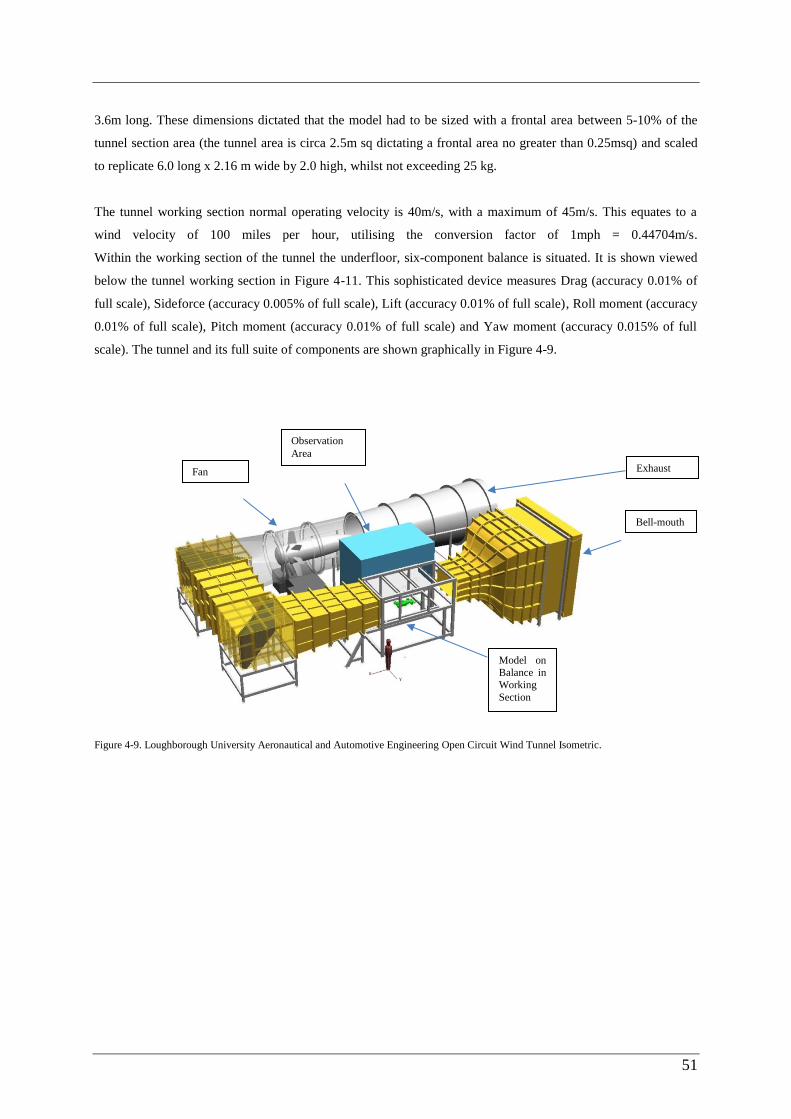
51
3.6m long. These dimensions dictated that the model had to be sized with a frontal area between 5-10% of the
tunnel section area (the tunnel area is circa 2.5m sq dictating a frontal area no greater than 0.25msq) and scaled
to replicate 6.0 long x 2.16 m wide by 2.0 high, whilst not exceeding 25 kg.
The tunnel working section normal operating velocity is 40m/s, with a maximum of 45m/s. This equates to a
wind velocity of 100 miles per hour, utilising the conversion factor of 1mph = 0.44704m/s.
Within the working section of the tunnel the underfloor, six-component balance is situated. It is shown viewed
below the tunnel working section in Figure 4-11. This sophisticated device measures Drag (accuracy 0.01% of
full scale), Sideforce (accuracy 0.005% of full scale), Lift (accuracy 0.01% of full scale), Roll moment (accuracy
0.01% of full scale), Pitch moment (accuracy 0.01% of full scale) and Yaw moment (accuracy 0.015% of full
scale). The tunnel and its full suite of components are shown graphically in Figure 4-9.
Figure 4-9. Loughborough University Aeronautical and Automotive Engineering Open Circuit Wind Tunnel Isometric.
Exhaust
Observation
Area
Fan
Model on
Balance in
Working
Section
Bell-mouth

52
Figure 4-10. LU AAE Wind Tunnel Bell-mouth & Exhaust.
Figure 4-11. Six-Component Balance below Tunnel Working Section.

53
Test Aim and Design
The aim of the test was to compare the aerodynamic performance of the scale model of a typical rectangular,
‘brick’ shaped construction load (designed to replicate the load profile most commonly lifted via a tower
crane) against the aerodynamic performance of the scale model of the Lifting Wing in a range of wind
speeds and yaw angles. This would therefore determine the increased aerodynamic performance of using the
Wing in a range of wind speeds and yaw angles.
The tunnel wind quantitative test results were then designed to be checked by two distinct qualitative
methods of aerodynamic analysis:
Firstly, surface flow visualisation analysis was undertaken at key stages of the wind testing allowing the
wind path to be established helping to explain the results of the wind test. This method makes invisible
airflow patterns visible, revealing air flow streamlines as they approach and flow across the Wing’s
solid surface. A series of flow visualisation photographs of the Brick and Wing models were taken at
key stages in the wind tunnel testing, allowing comparison of aerodynamic flow around the models.
Secondly, a preliminary dynamic test was undertaken providing a real-time visual indication of the
Wing’s aerodynamic characteristics under conditions reflecting, as closely as possible, suspension of
the Wing from a tower crane cable in wind conditions likely to be experienced on a tall building site.
No quantitative measurements could be taken during this test, purely a visual analysis of the Wing’s
aerodynamic performance.
These are both discussed in more detail in the following sections.
To ensure the wind tunnel test results were predicative of full scale results, the tests were planned to be
undertaken with a Reynolds number (Re) as close to the calculated full scale Wing, Re of 8.2 x10⁶,
calculated for a wind speed of 20m/s, where Re = Inertia Force / Viscous Force = (Density x Velocity x
Length) / absolute coefficient of Viscosity. This would then then reflect the accepted academic theory that if
the model has the same Re as the full scale application, then they are dynamically similar as the non-
dimensional function of Fluid Viscosity, Density, Pressure, and Temperature are the same for the model and
full scale.
To determine this for the Lifting Wing model, a number of Re sweep tests of both models were undertaken
(discussed in more detail later in this Chapter). The results of these sweeps showed that Re became invariant
above 1.5x10⁶. This demonstrated that the results obtained for both models would replicate the full scale
Lifting Wing in wind speeds of up to 90mph (current international standards for tower crane ‘in-service’
wind speeds with no aerodynamic aid are up to 20m/s or 45mph).

54
Building The Models
To undertake the planned test, two scale models had to be accurately constructed. After several attempts to
construct the models using plastic sheet and dense foam with limited success, it was decided that the models
would be built using a 2mm thick plywood veneer sheet forming the outer face of the models, fixed to a
plywood spar frame cut utilising a computer numerical control (CNC) machine. This form of construction
was inspired by the build method of acoustic guitars which have a sweeping curved form of similar radius to
the planned Wing model. The Loughborough University CNC wood router machine used for the model
making created the 3D frame elements from plywood using the Cartesian coordinate system (X, Y, Z) for
3D motion control. The model frame elements were firstly designed in the computer with a CAD/CAM
program. This allowed these elements to be cut automatically using a routing and trimming head to produce
finished parts to within 0.5mm accuracy, crucially important to ensure symmetry of the Wing model. The
2mm thick ply veneer was then bent and forming of the around the spar frame, fixed, glued, filled and
sanded and sprayed matt black to complete the models.
The resultant scale model of the Lifting Wing was built to an accuracy of +/-1mm, with the design based on
the NACA 0035 aerofoil. The chord length was 600mm, maximum width of 216mm and height 200mm,
with a cross sectional area of 0.0432m2. This equates to a 1:10 scale model of the full size Lifting Wing. It is
shown below mounted on the working section of the tunnel.
Figure 4-12. Scale Model Wing Mounted on the Working Balance of the Tunnel.

55
Figure 4-13. Scale Model ‘Brick’ Mounted on the Working Balance of the Tunnel.
Similarly, the 1:10 scale model of the typical construction load, the ‘Brick’, was built with the same
tolerances, having a chord length of 600mm, maximum width of 210mm and height of 200mm, giving a
reference area of 0.043m2. It is shown below similarly mounted.
Wind Tunnel Test Objective and Summary
The objective of the wind tunnel test was to generate quantitative data for the model’s drag (Cd), lift (Cl)
and pitching (Cp) moments at varying degrees of yaw and wind speed. The wind tunnel test was designed to
minimise systematic errors by considering and compensating for the three most likely causes of error which
were deemed as: error due to model or tunnel asymmetry; error caused by the wind forces acting on the
connection shaft between the models and the tunnel balance, thirdly any random or human errors. The
method of testing involved connecting, in turn, the reference Brick model, then the Lifting Wing, each
rigidly fixed to a steel connection shaft which is fitted through the floor of the working section of the tunnel
and connected to the balance (as shown above in Figures 4-12 and 4-13 above).
Once true zero (head to wind) position was established by undertaking a yaw sweep for each model, a run of
tests were undertaken for each model in turn. The reference areas of the models, the wind speed, barometric
pressure, air temperature, drag, lift, side-force, pitching moment, yawing moment and rolling moments, plus
their coefficients, were recorded by the tunnel computer data logger (Figure 4-15 is a live screen shot of the
Aerotech Balance OGI in test) at a range of wind speeds from zero to 40m/s. Each model was then rotated
(yawed) on the balance through two degrees away from true zero and all measurements recorded. This was
repeated by further two degree increments up to +/-20 degrees, then 1 degree increments up to a maximum
of +/-25 degrees yaw. Tests for each model were re-run after powering down the wind tunnel (effectively re-

56
setting, or zeroing the tunnel and its data logger) to determine the repeatability of results. All results taken
were within 5% of the initial result with no outliers, allowing the arithmetic mean to be utilisied for the final
results. Measurements for the Wing were compared to the comparable results for the reference Brick model,
ultimately demonstrating the aerodynamic improvement of the Wing.
Wind Tunnel Test Methodology
The test was conducted in four stages:
Firstly the steel connection shaft was mounted to the tunnel balance and the wind tunnel was run at
5m/s increments from zero up to 45m/s to determine forces due to shaft alone and allow balance
results for each model to be adjusted for shaft effects. To refine these results, a replica support shaft
of the same diameter as the one used to support each model was raised into the tunnel to a height of
450mm. Each model was then attached to the tunnel roof via the original support shaft and lowered
until it was just clear of the replica shaft fixed to the balance. This gave a more accurate balance
reading of the shaft value to be subtracted from each model final measurements.
Secondly, the Brick model was mounted on the steel shaft fixed to balance. The maximum velocity
(Vmax) was established by running wind tunnel from 0 m/s at 5 m/s incremental speeds, whilst
ensuring drag, lift, side-force, pitch, yaw and roll loads did not exceed 90% of the limit of the wind
tunnel balance. This was repeated for the Wing model, resulting in a Vmax of 40m/s, with
generated forces at just over 85% of the balance limit for the Brick model.
Thirdly, a Reynolds Number (Re) sweep for the Brick at zero degrees yaw was undertaken, over
incremental wind speeds from 0 to 40m/s. This allowed the calculation of the Re for the range of
wind speeds, plotted to determine the minimum wind speed at which the Re becomes a constant
(thus replicating full scale results). This was repeated for the Lifting Wing. Resulting Re values are
shown below in Figures 4-14 a&b. These demonstrated that above Re of 600000, there is relatively
little Re effect and results are as close to full scale as possible.
Figure 4-14a. Brick Re V's Cd.
CD
rag
Re
2.07E+05 4.15E+05 6.25E+05 8.46E+05 1.05E+06 1.25E+06
1.46E+06 1.51E+06 1.58E+06 1.64E+06 1.70E+06

57
Figure 4-14b. Wing Re V's Cd.
Finally, a series of tests for both the Brick and Wing models were run, recording all required forces.
The results of which are shown graphically in Figure 4-16 a&b below:
Brick Yaw Angle Vs CDrag for 30m/s and 40m/s;
Brick Yaw Angle Vs CLift for 30m/s and 40m/s;
Brick Yaw Angle Vs CSideforce for 30m/s and 40m/s;
Brick Yaw Angle Vs CPitch for 30m/s and 40m/s;
Wing Yaw Angle Vs CDrag for 30m/s and 40m/s;
Wing Yaw Angle Vs CLift for 30m/s and 40m/s;
Wing Yaw Angle Vs CSideforce for 30m/s and 40m/s;
Wing Yaw Angle Vs CPitch for 30m/s and 40m/s.
The results were recorded via the Aerotech Balance OGI, which allowed live recording of all the
required forces during the testing. A live screen shot of recorded coefficients is shown in Figure 4-15.
CD
rag
Re
2.06E+05 4.05E+05 6.22E+05 8.44E+05 1.04E+06
1.26E+06 1.46E+06 1.51E+06 1.58E+06 1.63E+06
1.69E+06 1.75E+06 1.81E+06

58
Figure 4-15. LU Wind Tunnel Aerotech Balance OGI. Recording Lift, Pitch, Drag, Side, Yaw, Roll & Wind Speed (at 30m/s)
Wind Tunnel Test Results
An overlay of the two crucial sets of results for the Wing and Brick Yaw Angles versus CDrag at 30m/s and
40m/s, and the Wing and Brick Yaw Angles verses CLift at 30m/s and 40m/s were graphically plotted, shown in
Figures 4-16a and 4-16b.
Figure 4-16a Wing and Brick Yaw Angles Vs CDrag for 30m/s and 40m/s.
The primary conclusions drawn from the CDrag overlay of the Wing and Brick were:
CD
RA
G
YAW ANGLE (DEGREES) Wing 30m/s Wing 40m/s Brick 30m/s Brick 40m/s

59
The Wing profile had a dramatically lower overall drag profile (in excess of 50% less CDrag than
that of the Brick), hence significantly less drag load would be induced on the cable and the crane, in all
wind conditions;
The Brick results plotted graphically exhibited a deep V, which shows a relatively large sensitivity to
wind direction changes, which dramatically increase drag and swing induced loading, hence load on the
crane. This feature was cross checked by undertaking flow visualisation on the Brick demonstrating a
substantially increased size of the wake area and reverse flow behind the Brick, meaning increased
drag;
By comparison, the Wing plotted results exhibited a smooth, shallow curve, showing relative
insensitivity to changes in wind direction, with less drag and swing induced forces, hence a more stable
flight. The flow visualisation on the Wing showed smooth attachment lines running to the sharp trailing
edge of the Wing, limiting the separated flow, or wake area behind the Wing, hence low drag;
The tendency for drag to increase as yaw angle increases dropped off earlier with the Wing, reaching
a maximum at around +/- 12 degrees (See Figure 4-16a) due to the sharp trailing edge and smooth
flanks, whereas the Brick drag forces continued to increase as yaw angle increases to a maximum at
around +/- 18 degrees as the wake area behind the Brick and reverse flow continued to grow. This
demonstrated the improved stability generated by the Wing, reducing drag imposed loads on the crane
in higher wind speed and with changeable wind directions.
Figure 4-16b. Wing and Brick Yaw Angles Vs CLift for 30m/s and 40m/s.
The primary conclusions drawn from the CLift overlay of the Wing (with Brick load inside the Wing) and
Brick were:
C L
IFT
YAW ANGLE (DEGREES) Wing 30m/s Wing 40m/s Brick 30m/s Brick 40m/s

60
Lift forces generated on both models were less than a 10th
of magnitude of drag forces and therefore
its influence is likely to be less significant;
The Wing profile had a lower overall lift profile (less than 1/4th
of the lift of the Brick at higher yaw
angles) hence significantly less rise-and-fall load would be induced on the cable and crane in higher
wind conditions. This feature was checked by comparing flow visualisation on the leeward side of the
Brick and the Wing. The Brick showed a more pronounced flow along the top and bottom edges, which
became more dominant at the higher yaw angle. In contrast the leeward side of the Wing showed more
fractured, multiple flow separation lines running from the nose toward the tail that drop away much
earlier. These markedly differing flow features would explain the differing lift forces generated on each
model;
The Brick exhibited a sharp and deep W profile, which signifies sensitivity of this shape to
increasing wind yaw angle, dramatically increasing lift and fall induced loading, hence load on the
crane. This would result in a rotation of the load when freely suspended from a crane, causing safety
issues when trying to fly and land the load safely;
The Brick also showed increasing sensitivity to higher wind speed as the results for 30 and 40m/s
diverge at higher yaw angles producing unstable flight characteristics as these factors increase;
By contrast, the Wing exhibited a smooth, shallow curve, showing relative insensitivity to changes
in wind yaw angle or wind speed, hence less rise-and-fall induced forces and more stable flight
characteristics.
Wind Tunnel Test Conclusion
Each of the tests described above were run twice and results analysed to show a high level of repeatability of
generated quantitative data for both model’s drag and lift forces at varying degrees of yaw and wind speeds. The
arithmetic mean was then taken to give the central tendency as there were no outlier results taken (all values
were within 5% of the initial the result). Side force and pitching moment were also measured in this method, but
ultimately deemed less critical, being relatively similar for both models, with slightly less pitching moment
generated by the Wing under extreme yaw angles and slightly higher side forces generated by the Wing at higher
yaw angles, creating a restoring yawing moment (a desirable self-correcting characteristic), ultimately producing
a stable flight in changing wind direction.
These results demonstrated a significant improvement in aerodynamic characteristics of the Wing, which would
at full scale provide significant reductions in critical forces generated by wind acting on the Wing, hence a
reduction in forces imposed on the tower crane. These results pointed toward the Wing significantly assisting the
Tower Crane Operator in their control of the tower crane in higher wind speed conditions experienced on a
construction site, thereby delaying his decision to take the crane out of service at a wind speed significantly
lower that the manufacturers prescribed ‘out of service’ speed.

61
These conclusions were further tested by conducting flow visualisation analysis of the Wing and Brick at
varying wind speeds and yaw angles in the wind tunnel, discussed in the following section.
Flow Visualisation Analysis
A series of flow visualisation photographs of the Brick and Wing models were taken at key stages in the wind
tunnel testing for each model to allow comparison of aerodynamic flow around the models. These were achieved
by coating the matt-black painted Brick and Wing models with a mixture of titanium dioxide, paraffin and
linseed oil. This white mixture responded to the surface shear stress of the air molecules and forms resultant flow
patterns at true zero degrees, plus and minus 10 degrees and plus and minus 25 degrees yaw at varying wind
speeds.
The details of this section of work is recorded in the 3rd
resultant paper of the EngD ‘Lifting Wing In
Constructing Tall Buildings – Aerodynamic Testing’ enclosed in Appendix C. Two example photographs of the
flow visualisation of the Brick model in Figure 4-17 and the Wing model in Figure 4-18 are shown below
indicating the differing flow patterns achieved by each model at the same yaw angle (-25 degrees) and wind
speed (40m/s) resulting in differing drag and lift forces generated, as discussed earlier. Detailed analysis of the
flow visualisation is included in Paper 3, Appendix C.
Figure 4-17. Brick nose at -25 degrees, 40m/s. Figure 4-18 Wing tail at -25 degrees, 40m/s.
Conclusion of Flow Visualisation
The flow visualisation testing showed a relatively clean, stable flow over the Wing at varying degrees of yaw,
demonstrating stable and predictable aerodynamic behaviour. The significantly reduced drag of the Wing
compared to the Brick, along with the Wing’s invariance of drag at higher yaw angle were the key factors in
proving the ability of the Wing to operate safely in higher and gustier wind conditions than a standard
construction load. These observations correlated with the quantitative data taken during wind tunnel testing and
reinforced the characteristics of stable and improved aerodynamic behaviour of the Wing over the Brick. These
results were further tested by conducting a dynamic test of the Wing suspended in the wind tunnel.

62
Preliminary Dynamic Test
The objective of this dynamic test was to conduct visual analysis of the Wing’s aerodynamic characteristics
under conditions reflecting, as closely as possible, suspension of the Wing from a tower crane cable in wind
conditions likely to be experienced on a tall building site. No quantitative measurements could be taken during
this test, purely a visual analysis of the Wing’s aerodynamic performance. This test was run three times and the
results recorded on video from the side window and roof window of the tunnel working section.
It was noted during this test that minor error in model symmetry and the inability to finitely level the model
effected the results and would need further refinement to achieve an accurate replication of full scale results.
The Wing model was freely suspended by three, 2mm diameter multi-strand steel cables, each with a 10kg
breaking strain. These were mechanically fixed to the top edge of the model, one directly above the centre of the
nose and two equally positioned on the top edge either side of the Wing, behind the widest section of the Wing.
The centre line of the three wires being over the centre of gravity of the model. These wires were sufficiently
long to allow the Wing to be suspended in the centre of the tunnel working section, with the wires running
through a hole in the roof of the tunnel and mechanically fixed externally to support the dead and live loads of
the model during testing (Figure 4-19a). This suspension method replicated the envisaged method of suspension
of the full scale Wing from a tower crane.
A series of videos were taken to record the behaviour of the Wing under increasing wind speeds from 0-12m/s.
These tests were then repeated with loads added inside the Wing (1kg metal plates fixed inside the wing profile)
to replicate 1, 2 and 3 tonne loads on a full scale Wing (Figure 4-19b). Observations were made on Wing
stability and flight behaviour from the side and roof windows of the tunnel working section.

63
Figure 4-19a. Wing Suspended for Dynamic Test. Figure 4-19b. Wing with Internal Load Plates Inside.
Dynamic Test Observations
The test was initially run with no internal load and videoed from the side window of the tunnel. The Wing
remained relatively static as the wind speed was increased from 0m/s to 9m/s, swinging slowly back by
approximately 5 degrees from the vertical as wind speed increased to 9m/s. At 10m/s the nose of the Wing was
observed to begin to move horizontally from left to right, stop and then return from right to left through the head-
to-wind at zero degrees yaw. This repeating oscillation increased in yaw angle as the wind speed was increase to
a maximum of 12m/s, whereupon the nose of the model, viewed from above, moved left to right whilst swinging
forward and back, describing a repeating infinity ( ) symbol movement over a distance approximately equal to
half the length of the model (300mm). This oscillation reduced as the wind speed was reduced to 9m/s,
whereupon the model became relatively static again, holding the 5 degree inclined position.
This test was repeated with a load of 2kg fixed inside the Wing. It repeated the pattern of the first test, with the
exception that the oscillation began at the increased wind speed of 11m/s and diminished as the wind speed was
reduced below 11m/s.
Finally a load of 3kg was fixed inside the Wing, again repeating the pattern of the first and second tests, with the
exception that the oscillation began at an increased wind speed of 12m/s and diminished when wind speed was
reduced below 12m/s.

64
The initial movement of the nose from left to right was deemed to be caused by a lack of absolute symmetry of
the model and it being slightly out of level horizontally due to unequal lengths of its three suspension cables.
These small errors created a gradually increasing turning moment on the model as the wind speed increases.
However, this also demonstrates the Wing’s self-correcting characteristic, producing stability of flight at full
scale, as this would ensure a slowly correcting nose-to-wind position of the Wing, desirable in changeable, gusty
wind conditions typified on congested city-centre tall building sites.
Implications of Results on Wing Design
This preliminary dynamic test demonstrated that the full scale Lifting Wing would need to be made
symmetrically, ideally utilising vacuumed formed thermoplastic technology or moulded carbon-fibre-reinforced
polymer, plastic or thermoplastic giving the added benefits of a higher strength to weight ratio and greater ability
to withstand impact deformation. Residual error could be corrected by adding a top mounted vertical stabilising
fin, fixed above the trailing edge of the Wing. The dynamic test also demonstrated the need for finite adjustment
of suspension cables to ensure truly level flight. Following this EngD, the dynamic test will be further refined by
the introduction of turnbuckles on each of the three suspension wires above the tunnel, allowing finite
adjustment of each cable length, and hence achieving true horizontal suspension of the model in the tunnel.
This test also demonstrated the proportional relationship of increasing load to more stable flight – the greater the
load carried inside the Wing, the less effect the non-symmetrical features of the model had on the stability of the
flight in increased wind speed. It also proved that the ultimate wind speed in which stable flight could be
achieved would be directly related to the size of the load carried inside the Wing.
Overall Conclusion
The wind tunnel test quantitative data correlated with the flow visualisation and preliminary dynamic test
observations. These reinforced the primary Wing characteristics of reduced drag in excess of 50% lower than the
Brick and of side forces on the Wing creating a restoring moment when flying in changeable wind direction
conditions, giving a desirable nose-to-wind behaviour These key characteristics at full scale should combine to
reduce induced loads on the tower crane and produce stable improved aerodynamic behaviour of the Wing when
compared to typical construction loads.
This conclusion demonstrates that the full scale Wing should achieve its primary purpose of increasing the
ability to lift construction materials safely in higher, or more gusty wind speed conditions than is currently
possible safely. Therefore the Lifting Wing design, if used on a tower crane of a tall building, should create a
valuable contribution in mitigating the effect of wind causing critical path delay during the construction of a tall
building, potentially reaping substantial time and cost savings. This knowledge and benefit could be transferable
internationally as, without exception, tall buildings across the world are built using tower cranes which are

65
negatively affected by wind during the build period, delaying completion, frustrating builders from completing
on time and budget and ultimately, owners from occupying their new tall buildings. These positive results will be
further demonstrated by future studies utilising a full scale Lifting Wing on a tower crane, discussed in Chapter
5.
4.7 SUMMARY
This Chapter described, in chronological order, the original research work completed to fulfil the aims and
objectives of the EngD, as clarified in Chapter 2 and in accordance with the research methodology, clarified
in Chapter 3.
Firstly, the taught element of the EngD was presented. This element was successfully completed and
officially recognised by Loughborough University awarding a Post Graduate Certificate with Distinction in
Engineering Innovation and Management in December 2008.
Secondly, the Literature Review of tall building construction was described and the UK tall building market
was profiled. The investigation into the future of tall buildings and the resulting working list of areas for
latter stage EngD research was described. This concluded Objective 1 of the EngD - ‘Undertake a Literature
Review and profile the UK Tall Building market for value, growth and demand sub-sectors’.
Thirdly, the design and development of the questionnaire tool designed to capture key information on the
international tall building process from targeted leading international tall building specialists was described.
The analyses of the resulting information and distillation to the key ‘wins’ & ‘losses’ on international tall
building projects was presented, highlighting recurring weaknesses in the approach to high rise construction
and areas for improvement. This concluded Objective 2 of the EngD – ‘to capture and analyse international
survey information from Tall Building experts to determine key ‘wins’ & ‘losses’ on tall building projects’.
Finally, the rationale behind the selection of one of the most common and critical construction ‘loss’ as the
focus for development of the innovative construction solution was described. The critiquing of the idea
against established theory, then modelling and wind tunnel testing was presented. The results of this
research were discussed and are presented in Chapter 5, Findings & Implication, validating the innovation.
This concluded Objective 3 of the EngD. – ‘to develop an innovative solution to one of the most critical and
common key Tall Building Project ‘loss’.

66
Each activity was described in detail and the relevance to the EngD research was clarified. Reference to the
published papers (Appendix A-C) were made where relevant.

67
5 FINDINGS & IMPLICATIONS
This chapter presents the main findings and discusses the implications of the research on the sponsor company,
the wider tall building industry and its contributions to existing theory and practice. It also provides a critical
evaluation of the research and suggests areas for further study.
5.1 THE KEY FINDINGS OF THE RESEARCH
The key findings of the EngD research and the conclusions drawn at each stage of research work are presented
below. The fulfilment of each objective by the research findings is also clarified.
5.1.1 STAGE 1
BACKGROUND THEORY - Literature Review and Market Report
The Background Theory work was conducted as an extensive literature review of tall building academic research
and of the UK tall building market providing the foundation for the EngD and allowing the refinement of the
objectives and selection of methods to be adopted. The seventeen main findings of this stage of the research are
described in full in the Tall Building Market Sector Report, Appendix D. These findings were distilled down to
the following nine key findings:
The tall building form is not a passing design trend in the UK, it is here to stay and is currently backed
from the upper echelons of Central Government down to popular public opinion;
The UK tall building is defined in this research as twenty storeys plus, due primarily to the change in
building methodology required. However, this only equates to mid-rise on the international tall building
stage;
Several new tall building clusters were being encouraged in London by Central Government, the
existing London Plan, CABE and by unsatisfied demand from the office, mixed use and residential
sectors;
The three biggest threats to the continued growth of the UK tall building market were the current US-
led global economic slump, UNESCO’s pressure to stop tall buildings being constructed close to
heritage sites of London (particularly near the Tower of London) and the London Mayor, Boris
Johnson’s threatened reverse of the current pro-tall building stance (having expressed his personal
disapproval of tall buildings that block historic views);
There are four types of UK tall buildings, driven by four distinct areas of demand, creating four sub
sectors of the market: the ‘fat’ office tower (18% of market demand); the ‘thin’ or ‘iconic’ office tower
(36%); the mixed use tower (18%) and the residential tower (28%);
In the fourth quarter of 2007, London had thirty nine tall buildings potentially reaching site in three to
five years, the South East had eight and the balance of the UK had thirty. The total estimated net trade
cost of which is £9.77 billion, directly equivalent to the construction budget for the 2012 Olympics;
The average gestation and build period for a UK tall building is eight years, made up of an average of
five years preconstruction and three years build period;

68
The average view of the many independent economic forecasts considered in this research prior to 2008
for the years 2008 to 2012, was one of sustained growth for both the commercial and residential drivers
of the tall building market, with an increasing focus on mixed use towers as the most efficient and
sustainable tall building format. This positive economic outlook has subsequently been tempered
throughout 2008 by the US led economic slump, reducing the UK’s commercial and residential markets
growth potential;
The UK tall building boom overlaid with 2006-2007 financial market buoyancy and the current
economic uncertainty are a mirror of the model conditions presented in the Skyscraper Index, a tool
used to forecast the economic downside of building tall. This infamous index historically demonstrates
that tall building construction follows the peak of a country’s economic cycle and is followed by a
significant economic slump. This overlay is presented in Paper 1, ‘Britain’s tall building boom now
bust?’, Appendix A and predicted an economic slump during 2008 (which was subsequently realised).
This work satisfied Objective 1, to ‘undertake a Literature Review and profile the UK Tall Building market for
value, growth and demand sub-sectors’.
FOCAL THEORY - Key Tall Building ‘Wins’ and ‘Losses’
This initial literature review resulted in a focus on several key areas of research during the Focal Theory stage of
the research. This was undertaken in two steps:
Firstly, data gained during the literature review was investigated in more detail for the nine key areas determined
as of critical importance to the UK Tall Building industry and formed the basis for the first paper ‘Britain’s Tall
Building Boom – Now Bust?’ published by the Institute of Civil Engineers for their Structures and Building
Journal in June 2009 (Appendix A).
Secondly, focus group and survey research methods were utilised to identify key strengths and challenges in tall
building construction. This provided the material for the second paper ‘The State of the Art of Building Tall’,
published and presented at the 5th International Structural Engineering & Construction (ISEC) Conference at the
University of Nevada, Las Vegas in September 2009 (Appendix B).
This work determined that one of the two most common, critical losses on tall building projects was the
detrimental effect of wind on the construction process of a tall building (the other being skill levels and tall
building experience of the project staff). This was distilled from the following three key findings:
‘Inclement weather (winding-off tower cranes)’, consistently ranked one of the two highest
construction risks, followed by ‘logistical problems (man and material access via hoist and crane)’,
‘superstructure cycle times / speed of erection’ and ‘façade installation’, all of which are directly related
to wind and its effect on the tower crane;
69
Tall building experts believed ‘construction programme surety’ and ‘cost certainty’ were the two
most significant risks to a tall build. The most important attribute of principal contractor was found to
be ‘innovative build approach and the provision of an experienced tall building team’, followed by
‘history of programme certainty’, ‘logistics management efficiency’, reinforcing the industry’s thirst for
innovation, desire for logistical, programme and therefore cost certainty. All of these findings are
directly tackled by the new contribution stage of this research undertaken on the Lifting Wing concept;
Of all tall building experts interviewed, 80% confirmed they would strongly embrace and promote
the use of an innovative construction technique that reduces the effect of wind on tower crane material
lifts on their tall building project. This finding supported the development of the Lifting Wing
innovation;
The conclusion of this stage of the research was that there was strong international demand for an innovative
solution to critical construction problems, the most highly ranked of which was wind negatively affecting the
build. Paired with the highest ranked desire of programme certainly and hence cost certainty, this signposted that
an innovative concept was needed to mitigate delays to the tall building programme duration by reducing the
effect of wind on the critical path activities of the tower crane. This finding led directly to the development of the
innovation of the Lifting Wing. The results gained from the questionnaire responses were analysed and formed
the basis for the second published paper ‘The State of the Art of Building Tall’ (Appendix B).
The work undertaken to this point satisfied Objective 2, to ‘capture and analyse international survey information
from tall building experts to determine key ‘wins’ & ‘losses’ on tall building projects’.
5.1.2 STAGE 2
DATA THEORY - Focus on a solution to one common and critical ‘loss’ with theoretical
research
This stage of research involved isolating the construction ‘losses’ reported in the above work, analysing the
underlying / root causes and determined the most important loss upon which to concentrate future research
efforts. The key finding was:
Wind and its critical impact on construction risk, the ability to deliver surety in programme and
therefore cost of a tall building was the clearly recurring theme of the questionnaire responses
returned by the international respondents.
This finding lead to a focus on ways to mitigate the effect of wind on the most critical construction
instrument of the tall building, the tower crane. During this stage of the research two ideas were conceived,
aimed at increasing the safety and speed of construction of tall buildings. The first was named the ‘Mag
Spanner’ and the second, the ‘Lifting Wing’. They were both aimed at satisfying the diametrically opposed
needs of time, cost and safety on tall building projects. The Mag Spanner was quickly developed and has
been introduced on many BLL steel frame projects. It is described in more detail in the Business Plan,

70
Appendix E. The Lifting Wing was deemed the more important of the two innovations, with the most
profound potential benefit and therefore became the focus for the final stage of research.
NEW CONTRIBUTION -Test and Prove the Innovation
This involved the development of the innovative construction technique to overcome the root cause of a key
construction ‘loss’. Of the two innovative ideas, the concept with the biggest potential impact on speed of
construction of tall buildings was determined as the Lifting Wing due to its potential to reduce the tall
building industry accepted norm of 40% down-time for a tower crane, thereby saving time on the critical
path of the tall building construction programme and hence, substantial costs. Experimental methodology
was employed to test the concept. This involved firstly, theoretical aerodynamic development, followed by
scale model building and finally obtaining quantitative data from wind tunnel testing and qualitative date
from flow visualisation and dynamic testing. The experimental analysis resulted in the following key
findings:
The wind tunnel testing quantitative data correlated closely with the qualitative flow
visualisation test findings and preliminary dynamic test observations. All three findings overlaid
confirmed the primary intended Wing characteristics of reduced drag in excess of 50% lower than
the reference Brick along with a desirable restoring nose-to-wind characteristic.
These key aerodynamic characteristics combined to reduce induced loads on the tower crane
and produce stable and improved aerodynamic behaviour of the Wing when compared to typical
construction loads.
The above findings demonstrated that the Wing achieves its primary purpose of increasing the
ability to lift construction materials safely in higher and more gusty wind-speed conditions than is
currently achievable.
The detailed findings from this aerodynamic research formed the basis for the final published paper which
was accepted by Structures and Engineering Editorial Panel for the final publication in 'Buildings’, in
fulfilment of the EngD formal requirements (Appendix C).
This work satisfied Objective 3, to ‘develop an innovative solution to one of the most critical and common key
Tall Building Project ‘loss”.
5.2 CONTRIBUTION TO EXISTING THEORY AND PRACTICE
This research makes the following contributions to existing theory and practice in the field of innovation in tall
building construction:
Providing a unique insight into the tall building market, its value and forecast growth. Determining
there are four distinct types of London tall buildings driven by four distinct areas of demand: the fat
office tower (18% of market demand); the skinny/iconic office tower (36%); the mixed use tower (18%)
and the residential tower (28%). The sum of these four markets meant that the demand for tall buildings

71
was unprecedented – ten London tall buildings were due to start on site in 2007, directly comparable in
size to the Manhattan skyscraper boom of the 1920’s. London had thirty nine tall buildings potentially
reaching site in the next three to five years, the South East had four and the balance of the UK had
fifteen. The total estimated net trade cost of which was £9.957 billion.
Determination of a proposed definition of a UK tall building. Above twenty stories in the UK a
building becomes technically distinct in its structure, services, vertical circulation, life safety and cost.
This is why they deserve a different classification – the UK tall building, which is directly comparable
to the classification of a global mid-rise building. It also determined that the mean gestation and build
period of a UK tall building is circa eight years.
Providing an overlay of skyscraper Index criteria on 2007 market conditions and the forecast of a
global financial crisis.
The development and implementation of a method to collect data from a wide spread of specialists
within the tall building sector of the construction industry. This captured the five key areas of the global
tall building industry across geographical and disciplinary spread, providing a snap shot of the state of
the art of the international tall building industry, the key risks of the tall building build process, desired
principal contractor key features, analysis of new techniques from overseas and other industries and
determination of the key tall building ‘Wins’ and ‘Losses’.
The development of two innovative concepts in response to the two most important issues identified
as challenges in tall building construction: improving the health, safety and productivity of the tall
building construction site; the Mag Spanner and the Lifting Wing. The Wing will be further developed
through future research following the EngD completion.
The development and implementation of a scientific method to test the aerodynamic improvement of
a model of the Wing over the typical construction crane load.
Contribution to partially redress the imbalance due to the vast majority of existing tall building
research being focused on the structural, services and architectural design. This research contributes to
the body of knowledge on the actual construction of tall buildings.
5.3 IMPLICATIONS/IMPACT ON THE SPONSOR
The EngD research process and outputs helped raise awareness and noticeably raised interest levels in tall
buildings within BLL. This was reflected in the significant increase in membership levels of the BLL High Rise
Community of Practice, an internal specialist interest group set up to focus on the tall building market sector,
chaired by the RE. Membership increased from 11 in 2007 to 32 by 2010. The EngD also assisted in raising
BLL’s professional profile externally in the London (and to a lesser extent the international) tall building market
sector and help reinforce BLL’s perceived level of appetite to build these relatively high-risk construction
projects. This was mainly achieved through the RE speaking at several tall building conferences and also through
networking at these specialist conferences and by contacts made during the research period. The EngD also

72
assisted in raising BLL’s profile within Academic circles as an innovator, supporter of the CICE, the EngD
programme and of higher education generally in the discipline of construction, tall buildings and innovation.
As a result BLL has benefited from:
A unique insight into the tall building construction market through the Market Analysis which
calculated the market value at nearly £10 billion (Net Trade Cost) and forecasted its growth prospects;
An investigation into the future of tall buildings which set out a wide range of potential areas for
further study during the remaining research period of the EngD. This enabled BLL’s EMT to influence
the direction of the final stages of research on what was deemed to be the most valuable of the research
options for the corporation;
Higher corporate visibility in the tall building industry, predominantly in London, then UAE and
America (where the RE presented), but also gave wider international visibility via engagement with the
respondents of the questionnaire by the RE at numerous international specialist conferences;
An increase in interest levels of BLL staff in the tall building specialist market sector, demonstrated
by the increase in membership to the BLL High Rise Community of Practice;
The first invitation to tender for a tall building since 2006. This was received directly from the
Client, W.R. Berkley Corporation, for the Lime Street Tower also known as the ‘Scalpel’, a bespoke tall
building to be constructed in the City of London, adjacent to the ‘Gherkin’ and opposite to Lloyds of
London. This lead came from two sources within BLL, one of which was via a contact made by the RE
during the EngD research;
A unique solution to mitigate a key tall building ‘loss’, providing a USP in the tall building
construction market.
The sponsor company was therefore in a unique position at the end of the EngD to maximise on the unique
position established in the London tall building market, but also on the international market.
5.4 IMPLICATIONS/IMPACT ON WIDER INDUSTRY
The Chartered Institute of Building published their Report Number 24 in June 2008 which found that two-thirds
of high-rise projects are finished late. Their research shows a high proportion of complex schemes are delayed.
The worst offending were high-rise construction projects, with two-thirds being completed late and almost a fifth
more than six months behind schedule. This reinforced the recognition of the need in the wider industry for
methods of mitigating delays to programme, especially for tall building projects.
The literature review highlighted substantial gaps in existing research undertaken in the actual build process of
tall buildings. The vast majority of existing tall building research had been undertaken in structural and
architectural design. This EngD work partially redresses that imbalance. The RE and co-authors of the papers
produced during the EngD believe this research has produced an important innovation that can potentially
provide substantial benefits to the tall building industry. Following the completion of the EngD and thesis

73
publication, funds are planned to be made available to build and test a full scale Wing, prior to taking the
proposition to market.
Additionally, falls on site of either materials or man are acknowledged across the industry as the biggest safety
hazard on a site. This area was researched in more detail as part of this study and culminated in the innovation
named the ‘Mag Spanner’. In trials on a BLL steel frame site, the spanners were well received by the steel frame
contractor and operatives. Their use during the trial significantly reduced the number of items dropped from
height over the period tested. It has since been adopted on several UK BLL sites with a steel structural frame.
This could have the potential to reduce accidents on site if adopted across the industry.
5.5 RECOMMENDATIONS FOR INDUSTRY/FURTHER RESEARCH
Having considered the findings of the research undertaken for this EngD, a number of recommendations for
further research can be made.
Firstly, this research uncovered a number of key wins and losses of tall building projects, many of which were
not selected for the final focus of this research. Several of these are considered to have potential far-reaching
implications on the building of tall buildings. Further research into the root causes of these wins and losses
would be beneficial to the industry. The two of the most significant are:
The industry’s leading practitioners believe that the construction industry is not keeping pace with
cutting edge designs for tall buildings and from a UK perspective, it highlighted that the UK was
deemed not to be keeping up with overseas construction industry developments and was ranked as joint
sixth out of seven countries for an innovative approach to construction. This shows the industry as a
whole and particularly the UK, needs to increase the level of innovation in the tall building construction
process. Barriers to innovation in the UK construction industry, particularly with respect to tall building
projects should be researched further, alongside methods to increase motivation to innovate.
The risk that was rated the highest in the tall building process across all geographical and
disciplinary sectors was the provision of experienced principal contractor staff, showing the majority of
the industry feel they are under-resourced with skilled and experienced tall building professionals. This
theme was also reflected by the top rated principal contractor attribute being ‘provision of an
experienced tall building team’. Additionally, the most common tall building ‘win’ was related to a high
quality construction and management team, and most common ‘loss’ was related to a poor quality
construction and management team, lacking tall building experience and skills. The recurring theme of
the responses throughout each section of the questionnaire point to an excess demand for tall builders
and insufficient supply of skilled resources to satisfy. Further research could investigate methods of
increasing the level of specialism to satisfy this demand and investigate ways to ensure this skill set can
be transferred to other types of complex major projects during the relatively cyclical tall building
market downturns.

74
Secondly, further research into the aerodynamic performance of the Lifting Wing and design refinement work is
warranted, including:
A further refined dynamic test of the scale model Lifting Wing will be undertaken by the RE on
completion of the EngD, allowing the model to be hung perfectly level in the wind tunnel. This is
planned to be achieved by the introduction of turnbuckles on each of the 3 suspension wires above the
tunnel which would allow finite adjustment of each cable length, hence achieving a true horizontal
suspension of the model in the tunnel. Additionally, the model would be further refined to ensure it is as
near to symmetrical as possible. The fitment of an adjustable tail fin would also be considered to ensure
the model sits at true nose to wind (zero degree yaw angle) when in circa 10m/s wind speed, thereby
preventing the previously experienced repeat oscillation which increased in yaw angle as the wind
speed increased. This would provide further refined aerodynamic results, better reflecting the increased
efficiencies gained by the lifting wing.
This would be followed by the next stage of the Wing development to be undertaken by the RE post
EngD, which is to construct a full scale model and dynamically test it utilising a Saddle Jib or Luffing
Jib Tower Crane on a sponsor company site. In this test, an experienced Tower Crane Operator will lift
a rectangular ‘brick’ shaped reference load in wind conditions approaching industry-recognised winding
off speeds. The load will then be placed inside the full scale Wing and lifted in the same wind
conditions. The Operator will be asked to note flight characteristics of each lift and determine the
increased wind speed in which the Wing can still be lifted safely. This quantitative analysis will rely on
the feedback from the Operator, rather than any measured force data. However, it is exactly this
Operator analysis that is used across the industry to determine the safe limit of lifting by cranes on
every site the world over. If Tower Crane Operators feel the Wing allows extended lifting in higher
wind conditions, then it will have succeeded.
An international patent has been applied for covering the Lifting Wing and research undertaken to date.
5.6 CRITICAL EVALUATION OF THE RESEARCH
At inception, the aim of this EngD was closely aligned with Bovis Lend Lease organisational strategy and
planned as a USP or key differentiator in winning tall building work. Its outputs were planned to be a
valuable resource in developing best practice solutions to meeting future tall building challenges in the UK.
This was unfortunately superseded by the global recession from 2007 until early 2013, when demand for tall
buildings reduced significantly or stopped completely in many countries. The only tall buildings to be
constructed during this period were those that had already started and were committed to financially. During
this period the EngD was threatened with termination as is was seen as a redundant work area by the
sponsor company. This stalled the research for a significant period as the RE was redirected to bid, win and
deliver projects. Fortunately, this started to change during mid-2013 as tall building projects began once
more to make financial sense and the sponsor company became keen to pursue tall building projects,

75
although in a more risk adverse position than before the global financial crisis. This caused prolongation of
and a disjoint in the research as the first 2 years were conducted in the peak of the market and the last 3
during the tale-end of a global recession and a cautious economic growth period, resulting in some disparity
in the research results. Fortunately, in the closing stages of the EngD the original aim is now re-aligning
with post-GFC corporate strategy and become meaningful once more. The first paper can now be considered
out of date and therefore warrants refreshing to reflect the current market status, forecast growth and overlay
the current market conditions on the Skyscraper Index criteria to determine if the next recession is indeed
imminent.
To this end, the questionnaire results determined from the focus group, pilot study and semi–structured
questionnaire interviews during 2007 and 2008 tall building conferences may reveal differing results if this
was repeated in today’s market conditions. This may also reveal new tall building ‘wins’ and ‘losses’. The
findings determined in this research may therefore be considered to be worthy of refreshing.
The final stage of this study is limited by the need for a full scale case study to prove that the experimental
findings are repeatable at full scale, as established aerodynamic theory suggests. This cannot be conducted
within the period of the EngD due to both time and financial constraints. However, further testing has been
described within this thesis, including the proposed full scale testing methodology. The next stage of
research, post EngD, would require significant funding to undertake and act as a post-EngD case study for
the Lifting Wing.
5.7 SUMMARY
This chapter presented the original findings of the research and the conclusions drawn at each stage of that
research work. The fulfilment of the overall EngD aim and of each objective by the research findings were also
clarified at each stage. The implications of the research on the sponsor company, on the wider tall building
industry and the contributions to existing theory and practice were discussed. Critical evaluation of the research
was presented and significant areas for further study were proposed.
The key findings of the research discussed earlier in Chapter 5 are summarised below, determined in three key
stages driven by the three objectives of the EngD:
Objective One
‘Undertake a Literature Review and profile the UK Tall Building market for value, growth and demand
sub-sectors’ - From early 2006 up to the freeze induced by the worlds faltering financial markets during
the first quarter of 2008, Britain experienced demand for tall buildings of an unprecedented high level -
in London alone, ten tall buildings had started, or were due to start on site between first quarter of 2007
to the fourth quarter 2008. This was directly comparable in size to America’s Manhattan Island
skyscraper boom of the 1920’s. The aims achieved in this first stage of research were: firstly, the
investigation the evolution of the UK tall building construction and determination of the reasons behind

76
its growth at previously unprecedented rates; secondly, the creation of the definition of the UK tall
building of 20 storeys and up, and contrasting it to the international tall building stage; thirdly, the
analysis of the differing types of demand and definition of the four resulting sub sectors of UK tall
building market; finally, the calculation of the size and value of the tall building market, the forecast of
its growth potential and the modelling against the ‘Skyscraper Index’, ultimately demonstrating that a
financial crisis was looming;
Objective Two
‘Capture and analyse international survey information from Tall Building experts to determine key
‘wins’ & ‘losses’ on tall building projects’ - This stage of the research captured the global state-of-the-
art of the tall building industry. This was achieved by: firstly, designing a questionnaire which tackled
the most pressing issues of the tall building process; secondly, targeting the questionnaire at the most
active tall building professionals around the globe; and thirdly, gaining an 80% response rate, giving a
great insight to the differences of opinion from Dubai to London, China to Chicago, Sydney to
Vietnam. The research was conducted in five key tall building areas: the current state-of-the-art of the
international tall building industry; the build process of a tall building; the tall building principal
contractor key features/issues; ‘wins’ and ‘losses’ inherent with past tall building projects; and new
techniques from overseas and other industries that could be adapted to the construction industry. The
analysed results gave some surprising conclusions, but offered a clearly signposted way ahead for
innovative construction of tall buildings, headlining on ‘wind’ and ‘expertise of project staff’ as the two
of the most common critical issues;
Objective Three
‘Develop an innovative solution to one of the most critical and common key tall building project losses’
– This stage of the innovative research was undertaken into one of the two most common critical issue
raised by the global tall building experts in the second stage of research: that of wind and its profound
negative effect on the construction critical path of the tall building. Theoretical and aerodynamic
research was undertaken, culminating in model making, wind tunnel testing and analysis of the ‘Lifting
Wing’. This demonstrated the Wing’s potential to allow building material to be lifted by tower cranes in
higher and more unstable wind conditions, reducing the construction duration of a tall building.
This EngD research fulfilled its vision of exploring the challenges that face the builder of tall, increasingly
irregular structures and determined a new solution to one of the most critical issues. This new solution, the
Lifting Wing, has the potential to improve the build speed, safety and hence commercial viability and
sustainability of tall buildings. In response to Col W. A. Starrett’s 1920’s analogy of the building of skyscrapers
being the nearest peacetime equivalent to war, the Lifting Wing provides air support as did the flying aircraft
carrier dirigible USS Macon.
To date there had been little research in this building area, in contrast to the voluminous research on the
structural, architectural and sustainability design of tall buildings. This EngD partially redressed that imbalance.

77
Figure 5-20. USS Macon over New York City, Summer 1933. US Naval History & Heritage Command.

78
6 REFERENCES
Akintoye, A. and Fitzgerald, E. (2000). A survey of current cost estimating practices in the UK. Construction
Management and Economics, 18(2), pp161-172.
Allen, J. (1999). Aerodynamics. The Science of Air in Motion. University of Michigan, Michigan City, MI, USA.
pp. 83–85.
Anderson, J. (2010) Fundamentals of Aerodynamics; McGraw-Hill: New York, NY, USA.
pp. 23–24.
Ankers, M. (2007). Welcome to the Future. Forecasting Conference, Construction Products Association & DTI.
Bar-Hilley, M. (2006). The Mayors New Powers. Evening Standard London. 17th
July.
Barlow, J. Rae, W. Pope, A. (1999). Low Speed Wind Tunnel Testing, 3rd
Edition, ISBN 0-471-5574-9, New
York.
Brandenburger, A.M. and Nalebuff, B.J. (1995). The Right Game: Use Game Theory to Shape Strategy. Harvard
Business Review, Jul-Aug, pp57-71.
Brooke, J. (1986). System Usability Scale – A Quick and Dirty Usability Scale. Digital Equipment Co Ltd.,
Reading, UK.
Building (2006). The Dream Towers of MIPIM. Building, 23rd
March. pp27.
CABE & English Heritage. (2003). Guidance on Tall Buildings.
Centre for Innovative and Collaborative Engineering (CICE), (2010). What is the Engineering Doctorate?
(Accessed May 2013). http://www.lboro.ac.co.uk/cice/
Chew M.Y.L. (2001). Construction Technology for Tall Buildings. Singapore University Press.
Cityoffices.net. (2006). Skyscrapers – Development Pipeline. (Accessed May 2013).
http://www.cityoffices.net/uk/london/skyscrapers.cfm
Construction Industry Forecasts. (2007-2011). Winter Edition 06/07. Construction Products Association,
London. ISSN 1470-028X.
Construction Plant Hire Association (CPA). (2008) Tower Crane Interests Group and Health & Safety
Executive. The Tower Crane Operator’s Handbook; HSE: London, UK. pp. 27–28.
Construction Task Force. (1998). Rethinking Construction: The report of the Construction Task Force to the
Deputy Prime Minister, John Prescott, on the scope for improving the quality and efficiency of UK construction.
Department of the Environment, Transport and the Regions, chaired by Sir John Egan. London,
Corporation of London. (2001). Economic Implications of Proposed Development at 110 Bishopsgate. Report by
Price Waterhouse Coopers.

79
CTBUH. (2006). Chicago International Conference Thinking outside the Box – Tapered, Tilted and Twisted
Towers. Dubai 2006.
Dorrell, E. (2006). Has the Tower Met Its Match? Architects’ Journal V224, pp10-11.
Drela, M. (1989). XFOIL: An Analysis and Design System for Low Reynolds Number Airfoils. Springer.
Berlin/Heidelberg, Germany.
Duffy, F. (2007). DEGW. Work Place Trends. Knowledge Management and the Creative Workplace. Office of
Government Commerce. London.
EC Harris & Knight Frank LLP. (2004). High Rise Residential Towers. Knight Frank Residential Research Ltd.
Egan, J (Sir). (1998). The Construction Task Force. Rethinking Construction. London, HMSO.
Egbu, C. (2004). Managing Knowledge…in the Construction Industry. DCAM Journal V11, pp301-15.
Egbu, C. (1999). The Role of Knowledge Management in Construction Competitiveness. Building Technology
and Management Journal. V25, pp1-10.
EGi’s London Office Database. (2006). Market Analysis, Issue 4, Oct-Dec2006. Estates Gazette.
Elliot, B. Jones, S. (2003). Jumpforming at Canary Wharf. Concrete Society, London. May 2003, V37.
Ettlie, J. (2006). Managing Innovation, Second Edition. Butterworth-Heineman, an imprint of Elsevier.
Fellows, R & Liu, A. (2003) Research Methods for Construction 2nd
Edition, London. Blackwell Science.
Forbes, J. (1996). Prefabrication In Tall Buildings: The Australian Experience. Proceedings of the Fifth World
Congress Collected Papers, CTBUH. 1996.
Fordham, P. (2007). Market Forecast, 2007. Economics, Building, 2nd
February 2007. CMP Information Ltd.
Foster, N. (2006). Exhibition, Sky High: Vertical Architecture. The Royal Academy, London.2006.
Fuerst, F. (2007). Russell Sage Foundation. Manhattan’s Financial Firms, Three Years After. Research
Associate at City University of New York’s Graduate Centre.
GLA, Greater London Authority. (2001). Strategic Views and the Skyline in London. Interim Strategic Planning
Guidance on Tall Buildings, 2001.
GLA, Greater London Authority. (2004). The London Plan. 2004.
Hodgekiss, A. (2007). Ad Giant Move to County Hall. Property Week. March 2007. CMP United Business
Media, London.
Hogg, R. McKean, J & Craig, A. (2012). Introduction to Mathematical Statistics. Seventh Edition, Pearson.
ISBN 10: 0321795431. P 10.

80
Independent, (2007). Gerkin Sold for a Record £600m. Business News Article, 6th
February 2007. London.
Insignia Richard Ellis Research. (2002). Tall Office Buildings in London, The Economic Realities, BCO 2002.
International Standard ISO 4302-1981. Cranes—Wind Load Assessment. Available online:
http://www.iso.org/iso/home/store/catalogue_ics/catalogue_detail_ics.htm?csnumber=10156 (Accessed May
2014).
Jones Lang Lasalle Research. (2006). UK Capital Markets Bulletin H2, 2006.
file:///C:/Users/Home/Downloads/2007-02_JLL_European_Capital_Markets_Bulletin.pdf (Accessed April
2007).
Kermode, A.; Philpot, D.R.; Barnard, R.H. Mechanics of Flight; Prentice Hall: London, UK, 2012.
Kitching, R. Jan 2006. Cloud Busters - The latest trend for tall buildings. New Civil Engineer, pp18-21.
Knight Frank Residential Research (2004): High Rise Residential Towers, London: Knight Frank LLP. London.
Latham, Sir M. (1993) Trust and Money: Interim report of the joint government/industry review of procurement
and contractual arrangements in the United Kingdom construction industry. London, HMSO.
Latham, Sir M. (1994). The Latham Report - Constructing the Team: Report from the Joint Review of
Procurement and Contractual Arrangements in the UK Construction Industry. London, HMSO.
Lawrence, A. (1999). The Curse Bites: The Skyscraper Index Strikes. Property Report, Dresdner, Kleinwort,
Benson Research (March).
Leading Edge Management Consultancy. (2006). White Paper W/G1 Innovation. www.leading-edge.co.uk
(Accessed June 2007).
Linklaters. (2002). Tall Office Buildings in London, Guidance on Planning, pp10-11. BCO.
Livingstone, K. (2001). Foreword to Interim Strategic Planning Guidance on Tall Buildings, Strategic Views
and the Skyline in London.
Lombard Street Research (1998). Growth Prospects of City Industries. Corporation of London.
London Property Research. (1998). High Buildings and Strategic Views. Economic Implications Working Paper.
Mason, S. (2007). CABE introduce tall buildings planning policy. News, Cabe.org.uk. (Accessed September
2007).
LPAC, London Planning Advisory Committee. (1998). High Buildings and Strategic Views. A Study for LPAC
by Building Design Partnership, London Property Research, London Research Centre and Ziona Strelitz
Associates.
McAlister, M. (2006). Marketing Tall Developments. Proceedings of the Talking Tall Conference. CB Richard
Ellis. London 2006.
Messenger, J. (2007) Forecast for Building and Construction. Morgan Stanley Research Analysts.
Met Office (2014) UK Weather: How stormy has it been and why? Jan 2014.
https://metofficenews.wordpress.com/2014/01/03/uk-weather-how-stormy-has-it-been-and-why/ (Accessed May
2014).
Morby, A. (2007) Confidence is Soaring. Construction Forecast 2007, Construction News, Emap Construct Ltd.

81
Morrell, P. (2006). The Economics of the Unusual. Director, Davis Langdon & Seah International. Proceedings
of CTBUH Conference.
OSHA. 1999. Big Blue Crane. Video by Occupational Safety & Health Administration Safety Inspector on site
the day of the collapse. Available online: http://www.osha.gov/video/bigblue.wmv (Accessed November 2013).
Planning Act (1990). Listed Building and Conservation Areas. Section 66.
Porter, M. (2004). Competitive strategy: techniques for analysing industries and competitors. New
York; London: Free Press.
Rawlinson, S. (2007). Office Boom Until 2010 – London’s ‘wall of work’ as Global Financial Centre. Partner,
Davis Langdon. Construction News. 1st January 2007.
Reiner, P. (2009). Next Generation Skyscrapers. Engineering News-Record. McGraw Hill ISSN 0891-9526.
Ridley, N (2007). REIT’s Effect on Construction. Executive Director, British Council for Offices & Junior Vice
President Colliers CRE.
Riewestahl, B. Lampson Transi-Lift ‘Big Blue’ Crane Collapse E.I.T., M.S., Penn State, 2010. Available online:
https://www.youtube.com/watch?v=zRvQlEbJnqc (Accessed May 2014).
Ross, B.; McDonald, B.; Vijay Saraf, S.E. Big Blue Goes Down. The Miller Park Crane Accident. Eng. Fail.
Anal. 2006, 14, 942–961.
Savills Research (2007). UK Residential Research Bulletin, No 56 Winter 2006/07. Savills PLC.
Skelton, I. Demian, P. Bouchlaghem, D. (2009). Britain’s tall building boom: now bust? Proceedings of the
Institution of Civil Engineers Structures and Buildings 162. June 2009, Issue SB3, Pages 161–168. doi:
10.1680/stbu.2009.162.3.161.
Skelton, I. Bouchlaghem, D. Demian, P. Anumba C. (2009). The State-of-the-art of building tall. Challenges,
Opportunities and Solutions in Structural Engineering and Construction. ISEC-5. September 2009, University of
Nevada, Las Vegas, USA. Taylor & Francis Group, London. ISBN 978-0-415-56809-8.
Skelton, I. Demian, P. Glass, J. Bouchlaghem, D. Anumba C (2014). The Lifting Wing in Constructing Tall
Buildings – Aerodynamic Testing. Proceedings of the MDPI AG (Multidisciplinary Digital Publishing Institute)
Buildings & Engineering Journal. Basel, Switzerland. ISBN 2075-5309. Accepted for publication on 12th
May
2014.
Smith, D. (2003). Beetham Tower, Liverpool – Innovation in Climbing Formwork. Concrete Society, London.
V 37, May 2003.
Smith, D. (2007). All Ahead Together. Economics Editor, The Sunday Times. Forecasting Conference, Emap
Communications.
Stansfield, K. (2004). Swiss Re sets the agenda for future high-rise buildings. Institute of Structural Engineers,
V82, May 2004.
Starett W.A. (1928). Skyscrapers and the Men Who Build Them. Simon & Schuster. NY, NY.
Strategic Forum For Construction. (2002). Accelerating Change. Proceedings for Rethinking Construction,
London, chaired by Sir John Egan.

82
Strike, James. Construction into Design: The Influence of new methods of construction on architectural design
1690-1990. Butterworth Architecture, 1991.
Strelitz, Ziona. (2005). Tall Buildings, A Strategic Design Guide. The British Council for Offices & RIBA
Publishing. ISBN 1 85946 168 9.
The Architects’ Journal (2002), Issue 41, 30th
May 2002. Technical and Practice ‘It’s a Breeze’.
The Times. (2007). Luxury property prices go through the roof as London flats set £4,200 sq ft record. 7th
February 2007. UK Business pp43.
THF. The Housing Forum. (2001). Rethinking Construction.
Thompson, I. (2006). Director, SKM Stadium. Stadiums. New Civil Engineer Sept 2006.
http://www.nce.co.uk/sydney-and-beyond/481814.article (Accessed June 2008).
Thornton, M. (2005) Skyscrapers and Business Cycles. The Quarterly Journal of Austrian Economics, V8, No1
(Spring 2005).
Wakisaka, T. (1995). Automated Construction System for High Rise Reinforced Concrete Buildings. Technical
Research Institute of Obayashi Corporation. Tokyo, 204, Japan.
Watts, S. (2006). Talking Tall, Proceedings of the 2nd
Annual Conference. Taylor & Francis London.
Willis, C. (1998). Building The Empire State. The Sky Scraper Museum. W Norton & Co. NY, NY.
Willis, C. (2007). Skyscrapers and Skylines in New York and Chicago. Director of The Skyscraper Museum. W
Norton & Co. NY, NY.

___________________________________________________________________________
APPENDIX A
PAPER 1 APPENDIX A
Skelton, I. Demian, P. Bouchlaghem, D. (2009). Britain’s Tall Building Boom: Now Bust?
Proceedings of the Institution of Civil Engineers Structures and Buildings 162. June 2009, Issue SB3,
Pages 161–168. doi: 10.1680/stbu.2009.162.3.161

Structures and Buildings
CONTENTSEditorialR. Smith 149
PapersNovelloadingtestsonfull-scaletaperedmemberportalframesG. I. B. Rankin, J. C. Leinster and D. J. Robinson 151
Britain'stallbuildingboom:nowbust?I. R. Skelton, P. Demian and D. Bouchlaghem 161
Seismicperformanceofwaffled-slabfloorbuildingsJ. Vielma, A. H. Barbat and S. Oller 169
NewmethodsforroadtunnelfiresafetyevaluationandupgradingG. A. Khoury, D. Walley and D. McWilliams 183
AxiallyloadedRCcolumnsstrengthenedbysteelcagesJ. M. Adam, S. Ivorra, F. J. Pallares, E. Giménez and P. A. Calderón 199
DiscussionTreatmentofriskandreliabilityintheEurocodesT. Vrouwenvelder 209
Bookreview 210
Structures and Buildings
Novel loading tests on full-scale tapered member portal frames
Britain's tall building boom: now bust?
Seismic performance of waffled-slab floor buildings
New methods for road tunnel fire safety evaluation and upgrading
Axially loaded RC columns strengthened by steel cages
www.structuresandbuildings.com
ISSN 0965-0911
Proceedings of the
Institution of Civil Engineers
volume 162 • issue SB3
June 2009
Proceedings of the
Institution of Civil Engineers
volume 162 • issue SB3
June 2009
www.structuresandbuildings.com
ISSN 0965-0911
Structures and Buildings
volum
e 162 • issue SB
3
June 2009
pages 149—
210
Institution of Civil Engineers

Proceedings of the Institution ofCivil EngineersStructures and Buildings 162June 2009 Issue SB3Pages 149–150doi: 10.1680/stbu.2009.162.3.149 Rob Smith
Chairman, Editorial AdvisoryPanel
Editorial
R. Smith MEng, CEng, MICE
This issue starts with an impressive set of full-scale loading
tests. It is rare to find such large-scale testing of portal frame
structures.1 The tests are based upon tapered portal frame
structures designed using BS 5950. Although this structural
type has existed for a long time, much of the testing was done
over 30 years ago before the common use of finite-element
(FE) modelling. The authors (Rankin et al.) propose that this
form of construction will become more popular as automated
welding technology becomes more widely available. Certainly,
the ubiquitous nature of portal frame modelling software is no
impediment to this form of construction. It is a pity that the BS
5950 code is about to be made obsolescent by the introduction
of Eurocode 3.
The next paper in the issue, by Skelton et al.,2 looks at
economic trends in tall building design. It examines the
cyclical nature of tall building construction, and suggests how
the ‘Skyscraper Index’ can be used to predict recession;
obviously a very topical subject. Although not a pure
engineering paper, the subject matter should be of interest to
all involved in high rise design and construction—it is the
market that drives the construction of high rise.
Vielma et al.3 look at a common form of construction, the
waffle slab, which is used frequently in Europe and Latin
America. It is also used frequently as part of the seismic
resistance of a building structure. The Spanish earthquake
resistant design code NCSE-02 gives rules for their use and it is
this application that is the subject of the paper. The
performance of waffle slabs is compared against moment
frames and, not surprisingly, the moment frames perform
better. The authors conclude that the prescribed ductility levels
stated within the code are too high and the best way to
improve the performance of waffle slabs is to increase their
depth!
Continuing a long string of papers examining structures and
fire, Khoury et al.4 look at the fire safety evaluation in tunnels.
In this case, the approach is holistic, looking at the social and
economic consequence of fires, methods of evaluation, escape
strategies and upgrading options. This is set against a
background of an EU directive setting minimum safety
standards.
Adam et al. provides a second paper on the subject of columns
strengthened by steel cages.5 The same authors have previously
written on the same subject.6 In this case the axial capacity of
the strengthened columns is reviewed, comparing experimental
and FE test results.
Lastly, we have some discussion on Eurocodes and a book
review.7,8 The discussion relates to risk and reliability in
Eurocodes, particularly with respect to the partial safety factor.
A number of cases are examined, reviewing how
simplifications in the factoring system can lead to some
unusual scenarios. An interesting read to anybody who ever
uses load factors.
REFERENCES
1. RANKIN G. I. B., LEINSTER J. C. and ROBINSON D. J. Novel
loading tests on full-scale tapered member portal frames.
Proceedings of the Institution of Civil Engineers, Structures
and Buildings, 2009, 162, No. 3, 151–159, doi: 10.1680/
stbu.2009.162.3.151.
2. SKELTON I. R., DEMIAN P. and BOUCHLAGHEM D. Britain’s tall
building boom: now bust? Proceedings of the Institution of
Civil Engineers, Structures and Buildings, 2009, 162, No. 3,
161–168, doi: 10.1680/stbu.2009.162.3.161.
3. VIELMA J., BARBAT A. H. and OLLER S. Seismic performance
of waffled-slab floor buildings. Proceedings of the
Institution of Civil Engineers, Structures and Buildings,
2009, 162, No. 3, 169–182, doi: 10.1680/stbu.2009.
162.3.169.
4. KHOURY G. A., WALLEY D. and MCWILLIAMS D. New methods
for road tunnel fire safety evaluation and upgrading.
Proceedings of the Institution of Civil Engineers, Structures
and Buildings, 2009, 162, No. 3, 183–197, doi: 10.1680/
stbu.2009.162.3.183.
5. ADAM J. M., PALLARES F. J., GIMENEZ E. and CALDERON P. A.
Axially loaded RC columns strengthened by steel cages.
Proceedings of the Institution of Civil Engineers, Structures
and Buildings, 2009, 162, No. 3, 199–208, doi: 10.1680/
stbu.2009.162.3.199.
6. ADAM J. M., IVORRA S., PALLARES F. J., JIMENEZ E. and
CALDERON P. A. Column–joint assembly in RC columns
strengthened by steel caging. Proceedings of the
Institution of Civil Engineers, Structures and Buildings,
2008, 161, No. 6, 337–348, doi: 10.1680/stbu.2008.
161.6.337.
7. VROUWENVELDER T. Discussion. Treatment of risk and
reliability in the Eurocodes. Contribution by A. N. Beal.
Structures and Buildings 162 Issue SB3 Editorial Smith 149

Proceedings of the Institution of Civil Engineers, Structures
and Buildings, 2009, 162, No. 3, 209, doi: 10.1680/
stbu.2009.162.3.209.
8. MINSON A. Book review. Developments in the formulation
and reinforcement of concrete. Proceedings of the
Institution of Civil Engineers, Structures and Buildings,
2009, 162, No. 3, 210, doi: 10.1680/stbu.2009.
162.3.210.
150 Structures and Buildings 162 Issue SB3 Editorial Smith
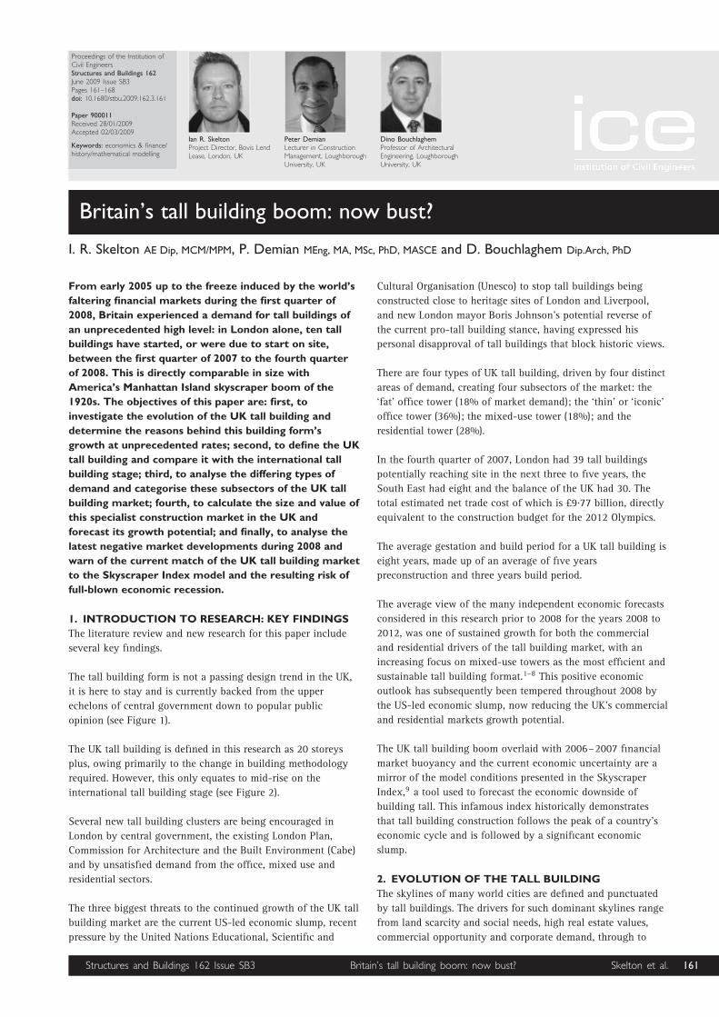
Proceedings of the Institution ofCivil EngineersStructures and Buildings 162June 2009 Issue SB3Pages 161–168doi: 10.1680/stbu.2009.162.3.161
Paper 900011Received 28/01/2009Accepted 02/03/2009
Keywords: economics & finance/history/mathematical modelling
Ian R. SkeltonProject Director, Bovis LendLease, London, UK
Peter DemianLecturer in ConstructionManagement, LoughboroughUniversity, UK
Dino BouchlaghemProfessor of ArchitecturalEngineering, LoughboroughUniversity, UK
Britain’s tall building boom: now bust?
I. R. Skelton AE Dip, MCM/MPM, P. Demian MEng, MA, MSc, PhD, MASCE and D. Bouchlaghem Dip.Arch, PhD
From early 2005 up to the freeze induced by the world’s
faltering financial markets during the first quarter of
2008, Britain experienced a demand for tall buildings of
an unprecedented high level: in London alone, ten tall
buildings have started, or were due to start on site,
between the first quarter of 2007 to the fourth quarter
of 2008. This is directly comparable in size with
America’s Manhattan Island skyscraper boom of the
1920s. The objectives of this paper are: first, to
investigate the evolution of the UK tall building and
determine the reasons behind this building form’s
growth at unprecedented rates; second, to define the UK
tall building and compare it with the international tall
building stage; third, to analyse the differing types of
demand and categorise these subsectors of the UK tall
building market; fourth, to calculate the size and value of
this specialist construction market in the UK and
forecast its growth potential; and finally, to analyse the
latest negative market developments during 2008 and
warn of the current match of the UK tall building market
to the Skyscraper Index model and the resulting risk of
full-blown economic recession.
1. INTRODUCTION TO RESEARCH: KEY FINDINGS
The literature review and new research for this paper include
several key findings.
The tall building form is not a passing design trend in the UK,
it is here to stay and is currently backed from the upper
echelons of central government down to popular public
opinion (see Figure 1).
The UK tall building is defined in this research as 20 storeys
plus, owing primarily to the change in building methodology
required. However, this only equates to mid-rise on the
international tall building stage (see Figure 2).
Several new tall building clusters are being encouraged in
London by central government, the existing London Plan,
Commission for Architecture and the Built Environment (Cabe)
and by unsatisfied demand from the office, mixed use and
residential sectors.
The three biggest threats to the continued growth of the UK tall
building market are the current US-led economic slump, recent
pressure by the United Nations Educational, Scientific and
Cultural Organisation (Unesco) to stop tall buildings being
constructed close to heritage sites of London and Liverpool,
and new London mayor Boris Johnson’s potential reverse of
the current pro-tall building stance, having expressed his
personal disapproval of tall buildings that block historic views.
There are four types of UK tall building, driven by four distinct
areas of demand, creating four subsectors of the market: the
‘fat’ office tower (18% of market demand); the ‘thin’ or ‘iconic’
office tower (36%); the mixed-use tower (18%); and the
residential tower (28%).
In the fourth quarter of 2007, London had 39 tall buildings
potentially reaching site in the next three to five years, the
South East had eight and the balance of the UK had 30. The
total estimated net trade cost of which is £9.77 billion, directly
equivalent to the construction budget for the 2012 Olympics.
The average gestation and build period for a UK tall building is
eight years, made up of an average of five years
preconstruction and three years build period.
The average view of the many independent economic forecasts
considered in this research prior to 2008 for the years 2008 to
2012, was one of sustained growth for both the commercial
and residential drivers of the tall building market, with an
increasing focus on mixed-use towers as the most efficient and
sustainable tall building format.1–8 This positive economic
outlook has subsequently been tempered throughout 2008 by
the US-led economic slump, now reducing the UK’s commercial
and residential markets growth potential.
The UK tall building boom overlaid with 2006–2007 financial
market buoyancy and the current economic uncertainty are a
mirror of the model conditions presented in the Skyscraper
Index,9 a tool used to forecast the economic downside of
building tall. This infamous index historically demonstrates
that tall building construction follows the peak of a country’s
economic cycle and is followed by a significant economic
slump.
2. EVOLUTION OF THE TALL BUILDING
The skylines of many world cities are defined and punctuated
by tall buildings. The drivers for such dominant skylines range
from land scarcity and social needs, high real estate values,
commercial opportunity and corporate demand, through to
Structures and Buildings 162 Issue SB3 Britain’s tall building boom: now bust? Skelton et al. 161

metropolitan signposting.10 This obsession with the still-
current form of tall, slender buildings can be traced to the
Italian patrician families who created the eleventh century
skyline of San Gimignano by building 70 tower-houses, some
50 m tall, as symbols of their wealth and power (see Figure 3).
This was most famously followed in the late nineteenth century
with the Manhattan skyline. This obsession with building tall
continues to spread worldwide and is forecast in this research
to grow into the future. Even after the World Trade Center
towers collapsed following a terrorist atttack in September,
2001, the tall building format is very much here to stay.
The development of increasingly sophisticated construction
materials and technologies has driven the evolution of the
modern tall building throughout the twentieth and early twenty-
first century. The resulting structures have reflected this
evolution in height, but the form has generally adhered to one of
only two design philosophies—straight up or stepped—owing to
twentieth century light-protecting planning laws (see Figure 4).
The new ‘iconic’ breed of innovatively designed tall buildings,
however, brings unprecedented challenges to the developers,
designers and not least, the builders: commercial feasibility
must be achieved; technological obstacles must be overcome;
cutting edge design must be converted into a built reality;
safety of its builders and occupants must be ensured; risk of
cost and programme overrun must be minimised. Tall
challenges for the tall building industry to surmount.
2.1. The rise and rise of tall buildings in London
Britain’s experience of tall buildings has been blighted by post-
war regeneration. The 1950s to 1970s produced a large number
of local authority housing towers and brutalist office towers
between ten and 30 storeys high. The high-profile failure of
many of these post war experiments was attributable to weak
design, detailing and construction, which led to a general
rejection of the high rise form in the 1980s and a focus on the
conservation and heritage building arenas. There were a few
exceptions to this rule in the first generation of UK tall
buildings, the most successful of which have now achieved
listed building status, including Centrepoint (grade II), BT tower
(grade II) and the Trellick tower (grade II*).
Figure 1. Possible future 150 m+ skyline of London
Figure 2. Is 300 m+ the future for London?
(a) (b) (c)
Figure 3. San Gimignano, (a) World Trade Center before (b) and after (c) collapse of its towers in September 2001
162 Structures and Buildings 162 Issue SB3 Britain’s tall building boom: now bust? Skelton et al.

Over the last ten years, general interest in tall buildings has
risen to new heights, both in the commercial and residential
sectors. This is evident on the supply side, especially in
London, where a pro tall building stance is notable in: The
London Plan;11 the number of planning proposals submitted
for tall buildings; the granting of planning consent to new
proposals such as Heron tower, the Shard in Southwark,
122 Leadenhall building, 20 Fenchurch Street, DIFA (or
Bishopsgate) tower and Columbus tower; the recent completion
of numerous tall buildings in various London locations such as
Paddington, the West End, the City (London’s financial district)
and Canary Wharf; the successful refurbishment of first-
generation tall buildings including Tower 42 and City Point. In
response to this favourable profile, signature architects are now
scrambling to design tall buildings.12
This high profile is also reflected in the demand side. There
is now a strong City ambition to build high. This has grown
from Foster and Partners’ form-breaking design for the Swiss
Re building, 30 St Mary Axe (the Gherkin), which won
support from Cabe, English Heritage and the City, all of
whom were keen to secure bespoke headquarters for major
commercial institutions.13 The continuing high-profile success
of 30 St Mary Axe undoubtedly led to increasing demand for
more commercial towers.14 The Heron inquiry followed and
forced the evolution of city policy, developing the concept of
an ‘eastern cluster’ in the city, not affected by St Paul’s
Cathedral heights, grid, strategic viewing corridors,15 or
conservation areas. The forthcoming 50-storey 122
Leadenhall building currently being built by Bovis Lend
Lease will become the focal point of this new tall building
cluster.
The rising profile of London as a ‘world city’16 over the past
decade, allied to the refocus of the planning system for high-
density developments and brown field schemes, has assisted
this growth in building tall. London, commonly seen as the de
facto capital of Europe, is consolidating its position as a world-
leading financial centre, second only in trade value to
Frankfurt. The new London mayor believes London is now
challenging Tokyo and New York as their only global
competitor. Planning policies laid down by the previous mayor
underpinned this vision, permitting the provision of world-
class office space and infrastructure and encourages ‘London to
continue to reach for the skies’.17
It is apparent from research undertaken for the present paper
that the current suite of tall buildings being constructed in the
heart of the City (122 Leadenhall, the Shard of Glass, the
Gerkin, Heron tower, 20 Fenchurch Street, the DIFA or
Bishopsgate tower and the Broadgate tower) were all
commissioned due to the threat of London Docklands on the
City’s position in the mid-1990s. The City responded by
relaxing plot ratios to encourage development. The reaction to
a ten year old threat is now finally hitting the streets, even
though the threat is long gone as Canary Wharf has been 90%
full for the last three years.
3. DEFINING A UK TALL BUILDING
The second objective of this paper is to define a UK tall
building and compare it with the international tall building
stage. This research has defined the UK tall building as between
20 to 80 storeys, approximately 70–300 m (depending on
whether the building has commercial or residential floor to
floor heights). A generally accepted definition of a tall building
in town planning terms is one which stands above the
prevailing skyline. A good construction definition has been
determined as a building which has technical and design
differentiation from its neighbours. Even with modern build
methods, above 20 storeys a building becomes technically
distinct in its structure, services, vertical circulation, life safety
and cost. Therefore, above 20 storeys, a different classification
is required: the UK tall building.
Research undertaken for this paper shows that of the 77 UK tall
buildings currently proposed, almost 70% by value are in
London. This report therefore focuses on London, but also
considers the South East and the balance of the UK (‘other
regions’).
3.1. London high rise global mid rise
London’s skyline is predominantly low rise with distinct
pockets of medium to high rise, allowing space for the St Paul’s
Cathedral sightlines to strategic London viewpoints.15 At the
top end of the London scale are the proposed London Bridge
tower and the Bishopsgate tower in excess of 300 m high,
(a) (b) (c)
Figure 4. Empire State Building (a) top, (b) bottom and (c) Fiera Milano
Structures and Buildings 162 Issue SB3 Britain’s tall building boom: now bust? Skelton et al. 163

containing 80+ storeys. The lower end of the London scale is
dictated by the need at this height for technological changes to
the way buildings are constructed, utilising tall building
techniques as opposed to low-rise construction techniques.
New York’s Manhattan Island is widely recognised as one of
London’s main competitors for the status of financial centre of
the world. Its skyline, by comparison with London’s, is
predominantly medium rise with widespread pockets of high
rise. A tall building (skyscraper) here is deemed to be 30 to
100+ storeys (although local fire codes change at 15 storeys).
In the last seven years America’s appetite for commercial tall
buildings has cooled, but residential demand remains strong
and international developments are beginning to influence
corporate decision making in New York, especially regarding
sustainable design.18 The future of the skyscraper seems
assured in New York City, even after the soul-searching in
Manhattan after the loss of nearly 3000 lives in the World
Trade Center collapse.
Tokyo is the second main competitor to London for the status
of financial centre of the world. The Asian skylines of central
Tokyo, Hong Kong and Shanghai, in comparison with
London’s, are predominantly high rise with isolated pockets of
low rise on the peripheries. Asia is regarded as the natural
environment of the very tall building, the format of which
makes sense where density and the urban infrastructure make
it the logical way to occupy land. High density is a historically
accepted norm in much of Asia. Many towers are
simultaneously going up in Hong Kong, Guangzhou, and the
other high-growth Asian cities. The tallest, densest buildings
are rising over rail stations, with airport access.19 With the
massive Chinese population rapidly industrialising in a modern
version of Victorian Britain, there is a boom in tall buildings
on an unprecedented scale. China currently has around 60,
300 m+ buildings, or ‘supertalls’, at some level of development.
This research finds that the UK tall building is therefore defined
on the international stage by its more conservative height,
individual architectural approach to the internal and external
form, its response to its non-regular site footprint and the
heritage of the surrounding city-scape. These local factors
generally result in high-quality, individualistic tall building
designs demanding high-quality building solutions. Modularity
and repetition are not seen as UK tall building traits, resulting
in a more costly tall building solution.
4. WHO IS DRIVING DEMAND FOR LONDON TALL
BUILDINGS?
Research undertaken for this paper shows that little academic
work has been done on analysing the tall building market and
categorising the demand for different types of tall buildings;
this forms the third objective of the current paper. Research
undertaken during 2007 has determined that there are four
distinct occupiers of tall buildings in London, driving demand
for four different types, or subsectors of tall buildings.
The first tall building subsector is represented by large
corporations wishing to relocate in a single building, requiring
a ‘fat’ tower with large floor plates of 3000 m2 gross and up to
50 000 m2 total area. This is usually a planned amalgamation
of various operations, aimed at creating synergies and savings
between business units, plus reducing facilities management
costs. Examples include HSBC, Citigroup, Barclays and most
recently, JP Morgan, who are moving to Canary Wharf as it
offered the right mix of floor plate, quality of space, size and
critical mass of complementary businesses. These types of
offices are now achieving an average rent of £70 per sq ft
(1 sq ft = 0.09 m2) across the seven London fringes.20
The second tall building subsector is represented by small
international companies demanding a prestige location in a
multi-tenanted, ‘thin’ or ‘iconic’ building. Their floor plate
requirement is 1000–2000 m2 gross. They value prestige, high
quality, shared facilities and opportunities for interrelations
with neighbouring businesses. The demand of this type of
occupier is shown by low vacancy rates and high rental yields
for these iconic buildings. These types of offices are regularly
achieving £100 per sq ft across London, a new record set
during the fourth quarter of 2006.20
A third, emerging tall building subsector is the mixed-use
tower, incorporating a mix of residential, retail, office and
possibly hotel and leisure space. This tall-building form shows
signs of increasing its tall building market share as they are
inherently efficient with higher densities, complementary
structural requirements and potential heating and cooling
shares between different occupiers systems. They are generally
located over, or close to, public transport hubs and are
generating an image of being an efficient and sustainable tall
building solution.
The fourth tall building subsector is the tall residential market,
rapidly growing in popularity owing to high potential returns
on investment. The renaissance of residential tall buildings is
attributable to increasing house prices outstripping build cost
inflation along with the rising profile of ‘city living’. This has
lead to a relatively new phenomenon of a price premium
relative to the height of the residential development.
Research undertaken for this paper shows the fourth quarter
2007 tall building market subsector split for London is: 54%
commercial towers (18% fat and 36% iconic); 28% residential
towers and 18% mixed use towers, shown graphically in
Figure 5.
The sum of these four tall building subsectors shows that
London’s demand for tall buildings was at an unprecedented
level in December 2007. The UK construction industry now
waits to see the impact of the US-led economic slump
throughout 2009.
18%
36%18%
28%
Office (fat)
Office (iconic)
Mixed use
Residential
Figure 5. London’s proposed tall buildings, the fourth quarterof 2007
164 Structures and Buildings 162 Issue SB3 Britain’s tall building boom: now bust? Skelton et al.

5. METHODOLOGY OF THE MARKET ANALYSIS
The market analysis undertaken for this paper created a unique
snapshot of the UK tall building market in the fourth quarter
2007. It captured the market’s mood, categorised the types of
demand, determined the market’s current value and was then
used to forecast its growth. The full picture of the tall building
market presented in this analysis was built up from a blend of
new data generated during this research, live information
gained from industry-recognised expert sources by way of
targeted interviews and questionnaires, plus in-house
theoretical and practical construction market knowledge. The
analysis concentrates on London as it forms almost 70% of the
current UK tall building market by value, but also considers
other areas of the UK.
5.1. Cataloguing current UK tall buildings
A catalogue of all proposed UK tall buildings was compiled to
determine the size of the current tall building market in the
UK, the type of tall building, the proposed height above
ground, the feasibility of actually being built and also captured
construction cost information, if available. This tall buildings
catalogue was then filtered to include only those tall buildings
deemed to be feasible of reaching site in the next three to five
years and exclude ‘visionary’ tall buildings with a low
likelihood of being built owing to their being out of context
with their location through extreme height, outlandish design,
impracticalities of proposed occupier use, or being a high-
density scheme submitted for planning approval to purely
increase site value. The catalogue contains 77 proposed UK tall
buildings. It has been broken down geographically into
‘London’ (which has 39), the ‘south east’ (which has eight) and
the ‘balance of the UK’ (which has 30) and then sorted into the
previously determined four tall building subsectors:
commercial (fat), commercial (iconic), mixed use and
residential for each geographic area. This breakdown is shown
in Figure 6.
5.2. Calculating current UK tall building market value
Definitive or reliable construction cost information can rarely
be found for the majority of projects owing to the confidential
nature of finance for tall buildings; therefore, the shell and
core construction costs of five Bovis Lend Lease tall building
projects were utilised. These tall building projects were selected
on the basis of being a London project that would feasibly
enter the construction phase with the next three to five years,
having had the cost plan checked for robustness during 2006
or 2007, the projects consisting of competitively tendered
packages under a construction management form of contract
and the projects proportionately representing the four
previously determined UK tall building market subsectors. The
project details of the five selected tall buildings are withheld
owing to the confidential nature of the project information, but
can be suitably described as
(a) tower 1: a signature-architect-designed tall commercial
building in the City; construction commenced in the first
quarter of 2008
(b) tower 2: a signature-architect-designed tall commercial
building in the City; construction commenced in the
second quarter of 2006
(c) tower 3: an existing tall commercial building in the City,
stripped, structurally extended and comprehensively
refurbished; construction commenced in the third quarter
of 2006
(d ) tower 4: a signature-architect-designed tall commercial
building in the City; construction due to commence in the
second quarter of 2008.
(e) tower 5: a signature-architect-designed residential tower in
London; construction due to commence in the third quarter
of 2008.
These figures were supplemented by independently published
construction cost projections for tower 6—London Bridge tower
(the Shard), the UK’s tallest mixed-use building, which entered
the construction phase in the first quarter of 2008.
The net trade shell and core construction cost per meter height
of building above street level was then selected as the most
reliable, publicly available metric common across all tall
buildings in the catalogue. This metric is historically reliable
and generally one of the first facts published for a tall building,
which can be used to extrapolate the value of the total UK tall
building market.
A range of costs were found across the six sample tall
buildings, the extremes of which were tower 5, the 44-storey,
slender residential tall building and tower 6, the 82-storey,
mixed-use London Bridge tower. The disparity of cost between
the two buildings is fundamentally attributable to height,
differing design complexity, the structural solution adopted,
floor plate sizes and the performance and complexity of the
cladding and services specified. These realistically reflect the
two book-ends of the UK tall building spectrum.
The average of the sample tall building net trade shell and core
construction costs per meter height was multiplied by the
cumulative height of the filtered catalogued tall buildings for
each geographical location in the UK, then factored utilising
published tall building cost location factors (London and the
South East cost index 1, the balance of the UK an average cost
index of 0.92).21 This results in the calculation of the total
value of the UK tall building construction market.
(NTC represents net trade cost, which, in this calculation is
defined as a tall building shell and core construction cost,
excluding demolition and enabling works, external works,
incoming services and fitting out, developer’s professional and
statutory fees, taxation, insurances, finance charges, disposal
costs and design and construction related professional fees,
VAT and any site abnormalities.)
Balanceof UK
SouthEast
0
5
10
15
Num
ber
ofta
llbu
ildin
gs p
ropo
sed
London
Geographical market area
Office (fat)Office (iconic)Mixed useResidential
Figure 6. Demand for UK tall buildings, the fourth quarter of2007
Structures and Buildings 162 Issue SB3 Britain’s tall building boom: now bust? Skelton et al. 165

(a) Tower 1. NTC £253 m/222 m height ¼ £1.14 m/m
(b) Tower 2. NTC £181 m/161 m height ¼ £1.12 m/m
(c) Tower 3. NTC £80 m/100 m height ¼ £0.80 m/m
(d ) Tower 4. NTC £257 m/160 m height ¼ £1.60 m/m
(e) Tower 5. NTC £55 m/140 m height ¼ £0.39 m/m
( f ) Tower 6. The Shard NTC £350 m/310 m height ¼ £1.13 m/m
Average construction (NTC) cost per m height ¼ £1.03 m/m
height.
Therefore, total construction value for tall buildings in London
and the South East ¼ cumulative height of catalogued tall
buildings 3 average NTC/m height ¼ (6968 m London + 422 m
South East) 3 £1 030 000/m ¼ £7 611 700 000.
Using the same method of calculation, the total construction
value of tall buildings in the balance of the UK (location factor
0.92) ¼ 2277 m 3 £1 030 000/m 3 0.92 ¼ £2 157 700 000.
Therefore, the total construction value for the current UK tall
building market ¼ £9 770 000 000.
To determine the potential UK tall building construction value
per year, the average gestation period of a UK tall building
needs to be determined. By analysis of the 20 most recently
awarded UK tall buildings for construction up until the fourth
quarter of 2007, the average UK tall building gestation period
(from project planning proposal date to completion of
construction date) has been calculated as eight years. This
consists of an average period of five years for preconstruction
(from initial project planning proposal to start on site) and
three years for construction (from start on site to completion of
construction) (see Figure 7).
Owing in part to the current uncertain economic climate, it is
not certain when any building on the tall building list will
progress from planning and preconstruction into the
construction phase and hence generate potential construction
spend for that year, so an equal spread over the average
gestation period of eight years must be assumed. This gives an
average annual construction spend (construction market value)
of £1 221 200 000 for the UK tall building market from 2007
until 2014 inclusive.
6. DISCUSSION
This forecast construction value for the UK’s tall building
market is of a scale directly comparable with the latest
government declared construction budget for the 2012
Olympics of £9.325 billion pounds over seven years (2006–
2012), but is not a one off event. If this building form is
nurtured, it has the potential to deliver this order of value year
on year into the future.
It is recognised that the London Olympic win has increased
delivery pressures on the current set of tall buildings. 2012 has
become an artificial deadline for a large number of major
projects, which will cause consolidation of work.22 There is
concern that the simultaneous start of construction of a
significant number of these tall building projects, running
concurrently with the Olympics, will overheat the construction
market, creating local shortages of skilled labour and materials
and force prices up by factors of up to 20% for steel
reinforcement and concrete. The 2007 market forecast report
summarises that the top and bottom of London’s construction
market is polarising, whereby large projects are suffering from
greater inflationary pressures, while smaller schemes retain a
more competitive edge.23
This forecast of rising construction costs has not noticeably
dampened the demand for the UK tall building, possibly
because its effect was swamped early in 2008 by the US’s
economic uncertainty and risk of global recession, the effects
of which are now starting to be seen in the UK tall building
market by the stalling of some speculative developments and a
requirement for higher pre-let percentages prior to construction
start.
Bringing this forecast up to date with recent economic
developments as of the fourth quarter of 2008, the amount of
commercial development in the UK has fallen to its lowest level
in five years24 and is directly attributed to tighter bank lending
conditions, deteriorating market sentiment and weaker growth
prospects for the global economy. This commercial fall could
affect three of the four tall building markets (fat office, thin/
iconic office and mixed use), the residential sector being
separately affected by the current UK housing market
stagnation caused by a lack of liquidity in the mortgage
market.
The tall building boom presented here, overlaid with 2006–
2007 financial market buoyancy and the current economic
uncertainty are a mirror of the model conditions presented in
the Skyscraper Index:9 a tool used to forecast the potential
economic downside of building tall. When London’s current
tall building market conditions are overlaid, there is an almost
perfect match. This infamous index historically demonstrated
that tall building construction follows the peak of a country’s
economic cycle and is followed by a significant economic
slump.25 This index was previously thought to be unable to
predict the UK tall building market as it was based on US
economic cycles and while its logic stood for historic cycles, it
Figure 7. Broadgate tower going up, the fourth quarter of2007
166 Structures and Buildings 162 Issue SB3 Britain’s tall building boom: now bust? Skelton et al.

unsuccessfully predicted the last two US economic slumps (the
last of which was 9/11 driven), owing to changing investment
criteria and expectations as the index was conceived in 1999.
However, this research shows that the recent history of
London’s tall buildings shows strict correlation to the
Skyscraper Index. London’s office market suffered downturns
in 1974, 1982, 1990 and 2002. The two most recent falls were
marked by the construction of London’s best-known
skyscrapers: Canary Wharf tower in 1991 and 30 St Mary Axe
in 2003. As previously proposed, the average gestation period
(from proposal to completion) for a UK tall building is eight
years and each economic cycle lasts for some ten years. This
makes it virtually impossible to get the timing right on tall
buildings.26
It is apparent from this research that the current suite of tall
buildings being constructed in the heart of the City, (122
Leadenhall, the London Bridge tower, Heron tower, 20
Fenchurch Street, the Bishopsgate tower or Pinnacle and the
Broadgate tower) which were all commissioned in the mid to
late 1990s, are due for completion between 2008 and 2011. If
the Skyscraper Index is to be believed, the current uncertainty
in the UK economy will degenerate into a full-blown recession
as these buildings are nearing completion over the next few
years.
7. CONCLUSION
This paper has investigated the evolution of the UK tall
building, and has determined the reasons behind this building
form’s growth at previously unprecedented rates. A definition
has been created of the UK tall building and it has been
compared with the international tall building stage. The types
of demand have been analysed and four subsectors of UK tall
building market have been categorised. The value of the UK tall
building construction market has been calculated, its growth
potential has been forecasted and the latest negative market
developments during 2008 have been discussed, warning of the
current match of the UK market to the Skyscraper Index model
and the resulting risk of full-blown economic recession.
The findings of this research will become more relevant as the
market hardens. Builders of tall buildings will increasingly
need to refine their approach to potential clients based on the
four demand types explained here and tailor the build
approach for each form of tall building. Speculative fat, thin/
iconic and mixed-use tall building developments will be the
first to disappear, while those being built with an element of
pre-let have a longer forecast and may be able to ride out the
current economic uncertainty. Residential towers, which have
not yet started on site, will be held back in increasing numbers
until the current month-on-month residential price drop
stabilises and the bottom of the market is seen to be reached.
Tower cranes across the London’s skyline have traditionally
been a highly visible measure of the health of the construction
industry as well as an accepted indicator of the strength of the
UK economy as a whole. If the view from the City to St Paul’s
is unblemished by Wolff’s, Liebherrs and Potains, then a slump
is on the horizon.27 If this indicator is to be believed, then the
London tall building market is thriving as almost 30 tower
cranes were counted on 1 January 2009 from London’s St
Pauls.
At the other end of the forecast spectrum, if the Skycraper
Index is to be believed, then both the UK tall building and
whole economic outlook is dire. Arguably one of the world’s
most enduring famous tall buildings, the Empire State
Building, closely followed the index’s prediction. On
completion it was nicknamed the Empty State Building owing
to its low occupancy rates until after World War II. Sales
publicity for the building claimed the feeling of looking out
from its viewing gallery was better than air travel. It was not
publicised that the viewing platform was only built because the
office space could not be sold.28 Will the UK’s tall building
momentum stall, will London’s skyline soon be host to a
myriad of sky-high, empty viewing galleries, or will the UK’s
new tall buildings continue ever upwards, unbending in the
current economic storm (see Figure 8)?
REFERENCES
1. See www.cityoffices.net.
2. CONSTRUCTION PRODUCTS ASSOCIATION. Construction Industry
Forecasts: 2007–2011. Winter Edition 07. Construction
Products Association, London, 2007.
3. EC HARRIS AND KNIGHT FRANK. High Rise Residential Towers.
Knight Frank Residential Research Limited, London, 2004.
4. FORDHAM P. Market forecast, 2007. Economics, Building.
CMP Information, London, 2007.
5. JONES LANG LASALLE RESEARCH. UK Capital Markets Bulletin
H2 2006, 2007. See www.joneslanglasalle.co.uk/
unitedkingdom/en-gb/Pages/Home.aspx.
6. LONDON PROPERTY RESEARCH. High Buildings and Strategic
Views. Economic Implications Working Paper. London
Property Research, London, 1998.
7. SAVILLS RESEARCH. UK Residential Research Bulletin. Savills,
London, 2007. Savills Research Report No 56, Winter
2006/07.
8. WATTS S. The cost of tall. 2nd Annual Conference on
Talking Tall, London, 2006.
9. LAWRENCE A. The curse bites: the Skyscraper Index strikes.
Property Report, Dresdner, Kleinwort, Benson Research
(March), 1999.
10. COUNCIL ON TALL BUILDINGS AND URBAN HABITAT. Chicago
International Conference: Thinking Outside the Box —
Tapered, Tilted and Twisted Towers. CTBU, 2006.
Figure 8. Proposed tall building clusters on London’s skyline
Structures and Buildings 162 Issue SB3 Britain’s tall building boom: now bust? Skelton et al. 167

11. GREATER LONDON AUTHORITY. The London Plan. GLA,
London, 2004.
12. STRELITZ Z. Tall Buildings, A Strategic Design Guide. The
British Council for Offices and RIBA Publishing, London,
2005.
13. MORRELL P. The economics of the unusual. CTBUH Talking
Tall Conference. Davis Langdon and Seah International,
Chicago, 2006.
14. LINKLATERS. Tall Office Buildings in London, Guidance on
Planning. British Council for Offices, London, 2002, pp.
10–11.
15. GREATER LONDON AUTHORITY. Interim Strategic Planning
Guidance on Tall Buildings, Strategic Views and the
Skyline in London. GLA, London, 2001.
16. LONDON PLANNING ADVISORY COMMITTEE. High Buildings and
Strategic Views. LPAC, London, 1998.
17. LIVINGSTONE K. Foreword. Interim Strategic Planning
Guidance on Tall Buildings, Strategic Views and the Skyline
in London. Greater London Authority, London, 2001.
18. FUERST F. Manhattan’s Financial Firms, Three Years After.
Russell Sage Foundation, New York, 2007.
19. WILLIS C. 2007. Skyscrapers and Skylines in New York and
Chicago. See www.skyscraper.org for further details.
20. EGi’s LONDON OFFICE DATABASE. Market analysis. Estates
Gazette, 2007, No. 4, Oct–Dec.
21. WATTS S. 2007. Tall Buildings: Cost Model, April 2007.
Davis Langdon, London, 2007.
22. THOMPSON H. S. New Civil Engineer, September 2006.
23. DAVIS LANGDON. Market forecast for 2007. Building
Magazine, 2007.
24. Savills and NTC Research. Commercial development
activity index. Property Week, 2008, June, 20–45.
25. THORNTON M. Skyscrapers and business cycles 2005. The
Quarterly Journal of Austrian Economics, 2005, 8, No. 1.
26. DAMESICK P. 2008. See www.cbre.eu/portal/page/portal/
uk_en/research.
27. MORBY A. Confidence is soaring. construction forecast
2007. Construction News. Emap Construct, London,
2007.
28. GARCIA J. M. The skyscraper boom: better than flying. The
Economist Print Edition, Dubai, London and New York, 1
June 2006.
What do you think?To comment on this paper, please email up to 500 words to the editor at [email protected]
Proceedings journals rely entirely on contributions sent in by civil engineers and related professionals, academics and students. Papersshould be 2000–5000 words long, with adequate illustrations and references. Please visit www.thomastelford.com/journals for authorguidelines and further details.
168 Structures and Buildings 162 Issue SB3 Britain’s tall building boom: now bust? Skelton et al.

___________________________________________________________________________
APPENDIX B
APPENDIX B PAPER 2
Skelton, I. Bouchlaghem, D. Demian, P. Anumba C. (2009). The State-of-the-Art of Building Tall.
Challenges, Opportunities and Solutions in Structural Engineering and Construction. ISEC-5, September
2009, University of Nevada, Las Vegas, USA. Taylor & Francis Group, London. ISBN 978-0-415-56809-8.
The state-of-the-art of building tall
I. R. Skelton Engineering Doctorate, CICE, Department of Civil and Building Engineering, Loughborough University, UK D. Bouchlaghem Professor of Architectural Engineering, Director, CICE, Department of Civil and Build-ing Engineering, Loughborough University, UK P. Demian Lecturer in Construction Management, Department of Civil and Building Engineering, Loughborough University, UK C. Anumba Professor and Head of Department of Architectural Engineering, Pennsylvania State University, USA
1 0INTRODUCTION
1.1 5Preceding research The paper by the same author titled ‘Tall Building
Boom – Now Bust?’ established that Britain experi-enced demand for tall buildings of an unprecedented high level from late 2006 to the financial freeze of late 2008. During this period in London alone, ten tall buildings have started, or were due to start on site. This is directly comparable in size to America’s Manhattan Island skyscraper boom of the 1920’s. The first paper investigated the evolution of the UK tall building and determined the reasons behind its growth at previously unprecedented rates; it created a definition of the UK tall building of twenty stories and above, which compares to the international tall building stage as mid-rise; it determined the average gestation and build period for a UK tall building as eight years, made up of an average of five years pre-construction and three years build period; it deter-mined the three biggest threats to the continued growth of the UK tall building market; it analysed the differing types of demand, defining four distinct sub sectors and calculated the size and value of UK tall building market as £9.77 billion, directly equiva-lent to the construction budget for the 2012 Olym-pics; it concluded by forecasting the UK tall build-ing market growth potential and modelled this
against the Skyscraper Index (Lawrence 1999), re-sulting in an almost perfect match (this infamous in-dex historically demonstrates that tall building con-struction follows the peak of a country’s economic cycle and is followed by a significant economic slump).
This second paper follows on from this work and sets out to establish the state-of-the-art of the inter-national tall building industry, concentrating on the four main geographical areas of Europe, UAE, USA and Asia Pacific. This has been achieved by: firstly, undertaking a series of interviews and pilot ques-tionnaires with targeted tall building industry spe-cialist, then utilising these findings to design a ques-tionnaire which tackles the most pressing issues of the tall building process; secondly, by targeting the questionnaire at the most active specialist tall build-ing professionals from each key discipline around the globe; thirdly, by delivering the questionnaires face to face, thereby gaining an 80 % response rate and over 150 valid responses; fourthly, by analysing the responses across all geographical areas and in-dustry disciplines, giving insight to the professional opinions ranging from Dubai to London, Shanghai to Chicago, Sydney to Tokyo, Holland to Vietnam. This paper will be followed by a more in-depth
ABSTRACT: Following on from the author’s first published paper titled 'Tall Building Boom - Now Bust?' which con-cluded that Britain's recent demand for tall buildings was of an unprecedented high level, directly comparable in size to Americas Manhattan Island skyscraper boom of the 1920’s, but that the construction market was ul-timately heading for a recession, this second paper determines the global state-of-the-art of building tall build-ings. This has been achieved by designing a questionnaire which captures the most pressing issues of the tall building process, targeting the questionnaire at the most active specialist tall building professionals around the globe, then delivering these questionnaires face to face, resulting in an 80 % response rate. The results give great insight to the consensus of professional opinion across the globe and across the specialist sectors of the industry. This paper investigates five key areas: the current state-of-the-art of the international tall build-ing industry; the build process of a tall building; the tall building principal contractor key attributes; ‘wins’ and ‘losses’ inherent with building tall and new techniques from overseas or other industries. The paper offers a clearly signposted way ahead for innovative construction of tall buildings.

analysis of the results, correlating industry specialist sector per geographical region, drawing out con-trasts and trends between specialism and geographi-cal location in the global tall building industry and isolating areas of global innovation in tall building construction that could be beneficially applied to the UK tall building industry.
The objective of this paper is to investigate five key areas of the global tall building industry:
The current state-of-the-art of the international tall building industry; The international build process of a tall building; The tall building principal contractors key fea-tures; Wins and losses inherent with past tall building projects; New techniques from overseas or other industries. The analysed results lead to some surprising con-
clusions, but offer a clearly signposted way ahead for the innovative construction of tall buildings.
1.2 6Pilot interviews and questionnaire development The research for this paper initially involved un-
derstanding the specific issues associated with build-ing tall, firstly on a UK basis, then expanding this to a global view. This stage commenced with a litera-ture review, followed by targeted structured inter-views held with the four most prolific tall building principal contractors in the UK. These interviews gave shape, direction and provided specialist insight to the tall building process, risks, experienced ‘pro-ject losses’ and some innovative ‘project wins’, plus signposted some areas demanding further develop-ment. This stage was followed by a series of pilot questionnaires, tested on academic and professional colleagues, each version being further refined and tailored to capture the most pressing issues of the tall building process. This ultimately led to the de-sign of the ‘State of the Art of Building Tall Ques-tionnaire’, issued by hand at Dubai and London tall building conferences and on the American Council on Tall Buildings and Urban Habitat website: http://www.ctbuh.org/Research/Overview/Constructionquestionnaire/tabid/454/Default.aspx, as featured in the global CTBUH Tall Building Newsletter, May 2008.
The final questionnaire design captured qualita-tive and quantitative data, aimed at building a com-prehensive picture of the global tall building indus-try. The respondents targeted for the questionnaire were the most active and high profile specialist tall building professionals around the globe, all attend-ing or presenting at the Council of Tall Buildings and Urban Habitat (CTBUH) 8th World Congress, held in March 2008 in Dubai and the New Civil En-gineer’s ‘Engineering Tall Buildings September
2008 Conference’, held in London. The results gained from over 150 questionnaire responses are presented and discussed in this paper.
2 1THE QUESTIONNAIRE
Questionnaire responses were gained from five tall building industry sectors, representing a cross section of specialists in the global tall building in-dustry:
The tall building End User or Client; The tall building Investor or Developer; The tall building Design Team Member or Con-sultant; The tall building Specialist Contractor or Sup-plier; The tall building Principal Contractor. A minimum of five and maximum of ten re-
sponses from each of the five specialist sectors were gained for each of the four geographical areas con-sidered, resulting in a good representation of the global tall building industry.
The questionnaire was split into six sections, the first five sections addressing each of the five tall building key areas and the sixth capturing respon-dent’s professional details, including current tall building project type, name and their industry spe-cialist sector. The analysed responses to each section are presented below.
2.1 7Section 1. International tall building industry – current state-of-the-art
This section set out to establish an overview of the tall building industry across the globe and the key issues inherent in building tall buildings.
The results showed that the majority of respon-dents from all specialist sectors and locations be-lieve that:
The international construction industry is not keeping pace with the latest, cutting edge design developments in tall buildings; The UK construction industry is not keeping pace with overseas construction industry develop-ments; The UAE has the most innovative construction industry, followed by China, the USA, Japan, Australia and the UK (joint), then Korea; The global demand for tall buildings will con-tinue to grow; The ‘iconic’ tall building form will take over from the more traditional, rectilinear form; The tall building format provides a sustainable future for the growing global population; The sustainability or ‘green image’ of a tall build-ing is growing in importance;

The sustainability of the construction process of a tall building is not as important as that of the fin-ished building; Safety is of paramount importance in the con-struction of tall buildings; Falls from height are recognised as a large con-tributor to health and safety incidents in the con-struction of tall buildings; A more innovative build approach should be sought to minimise falls from heights during the build process.
2.2 8Section 2. The build process of a tall building This section investigated the build process of a tall
building, wherein respondents rated fourteen risks inherent with a tall building project.
‘Principal contractor staff experience’, ‘inclement weather (winding-off tower cranes)’, ‘specialist trade procurement’ and ‘defects completion and handover for progressive occupation’ were consis-tently ranked the highest risk. These were followed by ‘logistical problems (man and material access, hoist / crane strategies)’, ‘superstructure cycle times / speed of erection’, ‘façade installation’, ‘services installation / commissioning’ risks. The next series of risks were ‘lift installation / builders use / com-missioning’, ‘roof / waterproofing / cleaning / spe-cialist architectural features’, ‘shell & core interface with fit-out works’. The lowest rated risks for the tall build process were perceived as ‘demolition of existing building / site clearance’, ‘ground condi-tions / foundations’, followed by ‘substructure con-struction’.
This section also investigated the respondent’s de-sire for innovation in tall building construction and their experience of structural frame build speeds, a critical-path activity of every tall building. It con-cluded that the majority of respondents would strongly embrace and promote innovative construc-tion approach on their tall building project, over a tried and tested construction technique (the example given was the potential use of an innovative crane accessory reducing the effect of wind on material lifts). It also found that the majority of respondents believe a typical tall building concrete frame can be built one floor to the next floor (floor cycle time) averaging 2-4 days. The majority of respondents also believe a typical tall building steel frame can be built with an average piece rate (number of pieces of structural steel erected per crane per day) of 16-20 pieces.
2.3 9Section 3. Tall building principle contractors
This section investigated the tall building princi-pal contractor, wherein respondents rated statements regarding experiences of procuring a tall building
project principal contractor, the perceived inherent benefits and most desired attributes.
The results showed that the majority of respon-dents believe that:
Tall building principal contractors offer a poor level of safety analysis and value analysis (buildability) of the design at preconstruction stage; Involving the principal contractor at an early stage in the tall building design does assists in de-livering value, safety, programme and cost cer-tainty; Procurement route options are severely restricted on tall buildings due to the limited number of high quality, capable principal contractors; Construction Management is currently the pre-ferred procurement route for a tall building prin-cipal contractor and this form will continue to grow in favour; Previous tall building experience is critical in the selection process of a principal contractor for a tall building project. This section also showed that Construction Man-
agement and Two Stage Lump Sum forms of Con-tract were the two most widely used forms to enter in contract with the tall building principal contractor on the respondents ‘live’ tall building projects.
Respondents were then asked to rate the impor-tance of nine inherent tall building project risks pre-viously disseminated from the structured interviews held with the four most prolific tall building princi-pal contractors in the UK. The results showed that the majority of respondents believe that ‘securing fi-nance’, ‘construction programme surety’ and ‘cost control / certainty’ were the three highest risks. These were followed by ‘the design process meeting expectation’, ‘securing tenant pre-lets’, ‘build qual-ity’ and ‘construction safety’. The lowest risks were seen as ‘declining demand for tall buildings’ and ‘regulatory and statutory requirements’.
Respondents were then asked to rate the impor-tance of principal contractor key attributes that they would consider in selecting the principal contractor for their tall building project. The most important at-tribute was the ‘provision of an experienced tall building team’. This was followed by ‘lowest cost’, ‘innovative build approach’, ‘history of programme certainty’, ‘logistics management efficiency’, ‘pro-curement expertise’ and ‘local knowledge and ex-perience’. Mid-rated attributes included ‘history of cost certainty’, ‘design management ability’ and ‘value management ability’. Lower ranked attributes included ‘safety record’, ‘established supply chain’, ‘political connections’ and ‘rank or position held in the construction industry’. The least important at-tribute was the ‘ability to offer project funding’.

2.4 1 0Section 4. Wins and losses inherent with building tall
This section investigated respondent’s experience of tall building project ‘wins’ or ‘losses’. ‘Wins’ were defined as things that were done well on a tall building project that significantly contributed to the success of the construction process. ‘Losses’ were defined as things that were not done well on a tall building project that negatively contributed to the construction process.
This section was not completed in 20% of the re-sponses. However, of the 80% completed, the quali-tative responses were highly varied, relating to man-agement techniques or systems, technological advances such as innovative material or methods, plus design related wins and losses. However, the majority of both wins and losses related to the per-ceived skills of the tall building project team.
The most repeated tall building project win was regarding a high quality construction and manage-ment team, with tall building experience from a round the globe. The second most repeated win was the early involvement of key trade contractors or specialist suppliers, positively influencing the cost, buildability and programme surety. Good and con-sistent team communication on project issues such as cost, programme and design drivers was also a re-curring theme. Five recurring types of innovative construction methods were also captured, including slipform advances, tower-crane / hoist advances, concrete related advances and delivery phasing or staging related advances. The majority of these tech-nological wins came from respondents across the five specialist sectors who were directly involved with super-tall towers in the UAE.
The most repeated tall building project loss was regarding a perceived low quality construction and management team, lacking tall building experience and skills. Noted weaknesses or specific areas where mistakes had been made included: poor management of the design team; poor trade contractor and sup-plier procurement; underestimating cost (inadequate budget), design complexity and programme; lack of understanding of efficient construction methods and techniques (relying on trade contractor knowledge, rather than in-house expertise).
2.5 1 1Section 5. New techniques from overseas or other industries
This section investigated new or innovative tech-niques or practices witnessed by the respondents, which could be adopted in the construction process of a tall building project. These ideas could be either from overseas construction methods, other industry practices, or simply areas where the traditional building approach seems outdated and in need of a
fresh approach. It was completed by 80% of respon-dents, whose observations covered a wide range of topics. They covered aspects from each project phase from detailed design development, through construction to completion, handover and occupancy of the tall building.
A selection of the most radical and potentially most beneficial from each project phase include:
Design development – A Dubai mixed use tall building utilised early specialist input to influ-ence the design to incorporate a structural ‘jump start’ at Level 8. This allowed the construction works for this section of building to run early, in parallel with the lower levels; Construction and completion – the Leadenhall Building in London developed a ‘bottom-up’ demolition of the existing building to allow an early start on excavation and substructure con-struction. (see Fig 1 and 2); Handover and occupancy – An Australian resi-dential tall building in Melbourne developed a phased completion strategy accepted by the statu-tory authorities, allowing early sectional comple-tion, occupation and easing project cash flow. Figure 1. Leadenhall Building, London. Bovis Lend Lease bottom-up demolition

Figure 2. Leadenhall Building, London. View on comple-tion – currently on hold
2.6 1 2Section 6. Respondents details
This section captured the respondent’s profes-sional specialist sector, or discipline, within the tall building industry, categorised as: the tall building End User or Client; Investor or Developer; Design Team Member or Consultant; Specialist Contractor or Supplier; and lastly the tall building Principal Contractor.
This section also captured the type of tall build-ing project the respondent was currently involved with, showing that the majority of respondents were working on ‘Commercial / Office’, followed by ‘Residential’, then ‘Mixed Use’ tall buildings. It also captured the respondent’s geographical location, their organisation / company, and the name of their current tall building project. Although the last two sets of information remain confidential, it is relevant to note that responses were gained from specialist involved with the majority of the current set of iconic tall and super tall buildings currently under design and construction in USA, UAE, London, Paris, Italy, Vietnam, Korea, Japan, Australia and across China.
This information will allow further analysis of the responses to be undertaken, investigating the corre-lation of each industry specialist sector across each geographical region, drawing out contrasts and trends between specialism and geographical location in the global tall building industry and isolating ar-eas of global innovation in tall building construction that could be beneficially applied to the UK tall building industry.
3 2DISCUSSION
The analysis undertaken for this paper created a unique snapshot of the global state-of-the-art of the tall building industry over the first to third quarters of 2008. It captured the industry’s buoyant mood and strong belief in continual growth in demand for tall buildings, especially for iconic tall buildings and its unexpected thirst for innovation in the build process over tried-and-tested approaches. It reflects the industry’s growing desire for sustainability in tall buildings, if not in the construction process it-self. A high level of appreciation of safety risks as-sociated with building tall was common across all
industry sectors and recognition of falls from heights as a primary cause of incidents on tall buildings.
It also shows that the industry’s leading practitio-ners believe that the construction industry is not keeping pace with cutting edge designs for tall buildings. This may be reflecting a frustration on the Design Team, Consultants and Client’s perspectives that their iconic designs cannot be constructed as cheaply or quickly as the more traditional rectilinear designs for tall buildings.
From a UK perspective, it highlighted some sur-prising results as the UK was deemed not to be keeping up with overseas construction industry de-velopments and was ranked as joint sixth out of seven countries for an innovative approach to con-struction. This shows the industry as a whole and particularly the UK needs to increase the level of in-novation in the tall building construction process.
The risk rated the highest in the tall building proc-ess was the provision of experienced principal con-tractor staff, showing the majority of the industry feel they are under-resourced with skilled, experi-enced tall building professionals. This was mirrored by responses in the principal contractor section, where it was strongly felt that procurement route op-tions were restricted due to the limited number of high quality, capable tall building principal contrac-tors globally. This theme was also reflected by the top rated principal contractor attribute being ‘provi-sion of an experienced tall building team’. Addition-ally, the most common tall building ‘win’ was re-lated to a high quality construction and management team, and most common ‘loss’ was related to a poor quality construction and management team, lacking tall building experience and skills. The recuring-theme of the responses throughout each section of the questionnaire point to an overheating tall build-ing construction market during the first three quar-ters of 2008, with insufficient skilled resources to cover the unprecedented demand for tall buildings.
It is interesting to note that the declining demand for tall buildings was seem as the lowest of nine tall building risks across all industry sectors and geo-graphic locations. Clearly, in the first to third quar-ters of 2008, the industry specialists did not foresee the Skyscraper Index (Lawrence 1999) about to bite. (this infamous index historically demonstrates that tall building construction follows the peak of a coun-try’s economic cycle and is followed by a significant economic slump).
4 3CONCLUSIONS
This paper has satisfied the objective of investi-gating five key areas of the global tall building in-dustry, across four main geographical areas of Eu-rope, UAE, USA and Asia Pacific:

It has established the current state-of-the-art of the international tall building industry; It has captured key features of, and ranks per-ceived risk in the international build process of a tall building; It rates the desired tall building principal contrac-tor’s key attributes; It has captured ‘wins’ and ‘losses’ inherent with past tall building projects; It has captured new ideas and techniques from overseas and other industries, potentially bringing benefit to the UK tall building industry. This initial analysis of the results lead to some
surprising conclusions, but offers a clearly signposted way ahead for the innovative con-struction of tall buildings. This paper will be fol-lowed up by a more in-depth analysis of the results, correlating industry specialist sector per geographi-cal region, drawing out contrasts between industry specialism and geographical location in the global tall building industry. This further research will also focus on isolating areas of global innovation in tall building construction that could be beneficially ap-plied to the UK tall building industry along with ar-eas clearly needing further innovation to improve the current state-of-the-art.
5 4REFERENCES
CTBUH Tall Building Newsletter, May 2008. http://newsletter.ctbuh.org/newsletter/08-05ctbuhnewsletter.html
Lawrence, A. 1999. The Curse Bites: The Skyscraper Index Strikes. Property Report, Dresdner, Kleinwort, Benson Re-search (March)
Skelton, I 2009.Tall Building Boom - Now Bust? ISEC-5, Sep-
tember 2009, University of Nevada, Las Vegas.

___________________________________________________________________________
APPENDIX C
APPENDIX C PAPER 3

Buildings 2014, 4, 1-x; doi:10.3390/buildings40x000x
buildings ISSN 2075-5309
www.mdpi.com/journal/buildings/
Article
Lifting Wing In Constructing Tall Buildings—Aerodynamic
Testing
Ian Skelton 1,*, Peter Demian 1, Jacqui Glass 1, Dino Bouchlaghem 2 and Chimay Anumba 3
1 School of Civil and Building Engineering, Loughborough University, LE11 3TU, UK;
E-Mails: [email protected] (P.D.); [email protected] (J.G.) 2 School of Architecture, Nottingham Trent University, NG1 4BU, UK;
E-Mail: [email protected] 3 Department of Architectural Engineering, Pennsylvania State University, University Park,
State College, PA 16801, USA; E-Mail: [email protected]
* Author to whom correspondence should be addressed; E-Mail: [email protected];
Tel: +44-(0)-790-408-4369.
Received: 23 December 2013; in revised form: 17 February 2014 / Accepted: 13 May 2014 /
Published:
Abstract: This paper builds on previous research by the authors which determined the
global state-of-the-art of constructing tall buildings by surveying the most active specialist
tall building professionals around the globe. That research identified the effect of wind on
tower cranes as a highly ranked, common critical issue in tall building construction.
The research reported here presents a design for a “Lifting Wing,” a uniquely designed
shroud which potentially allows the lifting of building materials by a tower crane in higher
and more unstable wind conditions, thereby reducing delay on the programmed critical
path of a tall building. Wind tunnel tests were undertaken to compare the aerodynamic
performance of a scale model of a typical “brick-shaped” construction load (replicating a
load profile most commonly lifted via a tower crane) against the aerodynamic performance
of the scale model of the Lifting Wing in a range of wind conditions. The data indicate that
the Lifting Wing improves the aerodynamic performance by a factor of up to 50%.
Keywords: aerodynamic; wind tunnel; tower crane; tall building; construction; innovation.
OPEN ACCESS

Buildings 2014, 4 2
1. Introduction
The primary concern in the engineering of tall buildings is the effect of the wind on the building’s
structure. Each uniquely shaped section of the world’s tallest tower (Burj Dubai) prevents the wind
from becoming organised and limits lateral movement [4].
The Lifting Wing applies this fundamental engineering concept to the actual build process of a tall
building and its life blood, the tower crane.
Previous research undertaken for “Britain’s Tall Building Boom: Now Bust?” [17] and “The State
of the Art of Building Tall” [18] provided a unique snapshot of the Britain’s unprecedented demand
for tall buildings in first quarter of 2007 to end of 2008 and the global state-of-the-art of the tall
building industry over the first to third quarters of 2008. This research captured the industry’s buoyant
mood and strong belief in continual growth in demand for tall buildings, especially for those of
“iconic” design. It also captured the industry’s unexpected thirst for innovation in the build process
over tried-and-tested approaches. The four key results were:
The international construction industry is not keeping pace with the latest, cutting-edge design
developments in tall buildings, and that the UK construction industry is not keeping pace with
overseas construction industry developments;
“Inclement weather (winding-off tower cranes),” consistently ranked one of the two highest
construction risks, followed by “logistical problems (man and material access via hoist and
crane),” “superstructure cycle times/speed of erection” and “façade installation,” all directly
related to wind and its effect on the tower crane;
Tall building experts believe “construction programme surety” and “cost certainty” were the
two most significant risks of a tall build. The most important attribute of a principal contractor
was determined as “innovative build approach and the provision of an experienced tall
building team,” followed by “history of programme certainty,” “logistics management
efficiency,” reinforcing the industry’s thirst for innovation, as well as desire for logistical,
programme and therefore cost certainty;
Eighty percent of tall building experts interviewed would strongly embrace and promote the
use of the innovative construction technique that reduces the effect of wind on tower crane
material lifts on their tall building project.
The conclusion of that paper’s research was that there was strong international desire for an
innovative solution to critical construction problems, the most highly ranked of which was wind
negatively affecting the build. Paired with the key desire of programme certainty and hence cost
certainty, this clearly signposted that an innovative concept was needed to mitigate delays to the tall
building programme duration by reducing the effect of wind on the critical path activities of the tower
crane. This focused the final stage of the research on the design and testing of an innovative concept
named the “Lifting Wing,” aimed at directly addressing this industry need.
This paper describes the scientific advancement in applying aerodynamic theory, refined via
modelling and testing, to a specific aspect of the building process of a tall building with potentially
significant time and commercial benefits. The specific research undertaken in design, modelling and
methodologically testing an aerodynamic shroud, was aimed at reducing the wind-induced load on a

Buildings 2014, 4 3
tower crane and the construction material being lifted, thereby allowing lifting in higher wind
conditions, reducing the UK average of 40% down time for a tall building tower crane. This would
therefore potentially reduce very costly wind-induced critical path delay to a tall building
construction period.
1.1. Wind and its Effect on Tower Cranes—The Life Blood of the Tall Building
Tower cranes have come to symbolize the construction industry and perform an indispensable
service in moving material components horizontally and vertically to their required positions. They are
central to mid- and high-rise building projects [15]. They have become internationally recognised as a
highly visible gauge of a city’s economic growth. In the UK, if the view of London’s skyline from the
city to St Paul’s Cathedral is unblemished by Wolff, Liebherr and Pontain cranes, then a slump is on
the horizon [10]. In the US, the popularity of tower cranes has been slower to develop; however, in
2006, Miami was named “Crane City,” as over 300 tower cranes were estimated to be working [16].
It is universally recognised that the tower crane’s main weakness is the debilitating affect that high
or gusting wind conditions can have on their ability to perform their critical construction role, hence
there is a risk of delay to the tall building programme through a drop—or even halt—in the
construction productivity rate. This delay can have huge commercial and reputational consequences for
the builder if a tall building project is not completed and handed over in accordance with the
construction contract dates.
There have been many technical advancements in computerisation, communication and control of tower
cranes, the latest of which are integral to new cranes and available as retro-fit kit for older cranes [14], all
aimed at improving productivity and safety. However, there have been no advancements aimed at the
crane’s oldest adversary—wind. The Lifting Wing aims to address this imbalance.
Wind forces exerted on the lattice structure of a tower crane and the construction load suspended
from the crane hook directly affect the ability to safely operate and control a crane and its construction
material load. The higher the wind speed, the greater the force exerted on the crane and load, and the
greater the likelihood of having to shut down crane operations and hence site productivity on
programme critical activities drops. The force exerted is wind pressure, caused by air particles
travelling at speed and hitting a stationary object—in this case, the crane structure and its bulky
suspended load. Wind pressure varies as the square of wind speed. Therefore, if wind speed doubles,
the wind pressure increases by a factor of four. A relatively small increase of wind speed can therefore
have a significant effect on the safe lifting operations of a tower crane.
Tower cranes are designed to international standards that specify the “in-service” wind speed that a
crane must be able to withstand and operate safely. These are typically 14 m/s (31 mph) for mobile
cranes and 20 m/s (45 mph, Beaufort Scale Gale Force 8) for tower cranes [8]. However, the reality of
the construction site is that the Tower Crane Operator will decide to take the crane out of service at a
wind speed significantly lower that the manufacturer’s prescribed “out of service” speed, due to their
increased difficulty in safely controlling the crane. This is recommended practice in the UK crane
industry [5]. The primary reason for the inability to control the crane is due to the effect of the wind
pressure on the construction load being lifted, rather than the crane structure itself. Wind pressure
acting on the load suspended at the end of the tower crane’s lifting cable results in increasing difficulty

Buildings 2014, 4 4
for the operator controlling the crane’s operations of lift, swing, travel, lowering and landing of loads
on a congested construction site. This causes a significant safety risk, not only for the crane operator,
but for any operatives in the vicinity of the crane and its load. This effect results in the crane ceasing
operations at relatively low wind speed with a relatively frequent occurrence, hence critical path
programme activities are commonly delayed.
1.2. The Effect of Wind on Suspended Loads
Strong winds tend to gust rather than blow consistently. This is amplified in tall building
construction site locations which are generally in, or adjacent to, built-up clusters in city centres.
The neighbouring buildings tend to break up the relatively smooth flow of wind over open land and
cause turbulent or separated flow. This turbulent flow of air across a tower crane and its load can result
in an induced rotating (yaw) and swinging motion (drag caused by a gusting wind) on the suspended
construction load, pushing it out of balance, increasing the radius from the centre of gravity of the
crane and therefore the overturning moment on the crane, potentially making the tower crane unstable.
For a relatively light load with a large surface area, such as formwork shutters for concrete frame
buildings, steel floor pans for steel frame buildings or cladding panels, this situation will occur
significantly below the tower crane’s design wind speed.
For example, a wind speed of 14 m/s (30 mph) generates a wind load on a 2.5 m × 1.3 m (8 ft × 4 ft)
standard formwork shutter of 372 Newtons (N). If the wind speed increases by circa 50% to 20 m/s
(45 mph), the wind load rises to 740 N an almost 100% increase of load. If this wind blows from
behind the crane, the load radius will be significantly increased, potentially overloading the crane. For
example, a formwork shutter weighing 750 kg with an area of 3.25 m2 and suspended on a 27 m cable
will move 1.4 m from the vertical when subjected to a 14 m/s (30 mph) wind. Moving the load radius
by this distance on a 35 tonne capacity crane with a 34 m main boom working at 18 m radius would
reduce the rated capacity from 950 kg to 640 kg. If this occurs close to the lifting and radius limit of a
tower crane, the result could be a catastrophic crane collapse.
This has occurred many times across the world with disastrous effect, the most famous of which is
“Big Blue,” a giant Lampson Transi-Lift crane that collapsed due to the effect of wind on its load
whilst building Miller Park, the Milwaukee Brewers Stadium, USA [12], which was recorded by the
Occupational Safety & Health Administration safety inspector on site the day of the collapse [11]. It
had a rated capacity of 1500 tonnes and was lifting a load of 450 tonnes, well inside its maximum
capacity. Upon investigation by independent specialist bodies, the concluded primary factor of the
collapse was the high wind load acting on the section of roof being lifted and lack of consideration of
those loads on the crane’s rated capacity [13].
2. Hypothesis
Conclusions from the earlier published paper summarised above [18] which signposted a
widespread demand for innovation in the area of wind and its negative effect on the construction
process, along with research undertaken in aerodynamic theory and site observations of the effect of
wind force on a suspended load of a tower crane on many of the authors’ construction projects, led to
the idea of reducing the effect of this force by sheathing construction materials in an aerodynamic

Buildings 2014, 4 5
profile during lifting operations. This would reduce the wind force effect on the load, create more
stable flight characteristics, ultimately reducing the loads imposed on a tower crane and thereby
increasing the ability to lift safely in challenging wind conditions.
Various profiles were investigated to achieve the best compromise of two diametrically opposed
requirements: that of an aerodynamic shape and the ability to allow large and irregular shaped
construction materials to be encapsulated within the aerodynamic profile. A section of an aerofoil
(a two-dimensional wing) in a horizontal orientation was ultimately selected, as established
aerodynamic research shows that at low approach angles the air flow is able to follow the curve of the
upper and lower surfaces of the aerofoil closely, then join smoothly towards the trailing edge,
minimising eddies [2]. There remains a relatively high pressure region at the front, but the low
pressure at the rear is much closer to atmospheric pressure, resulting in a resistance (coefficient of
drag, CDrag) that is around 20 times less than a flat sheet and 10 times less than a cylinder profile [9].
CDrag is a dimensionless quantity that is used to quantify the drag or resistance of the Wing in air. The
lower the CDrag, the less aerodynamic drag on the surface of the shape.
Figure 1 is a view from above a section of aerofoil and shows the smooth flow of air from left to
right over the streamlined shape, but that flow separation occurs progressively as the aerofoil is turned
at an oblique angle to the air flow (yaw angle). The Lifting Wing aerofoil design aims to prevent this
“stall” effect by being freely suspended from the tower crane lifting cable, ensuring it is free to rotate
and remain “nose to wind,” presenting the minimal surface area to the prevailing wind direction,
thereby minimising the effect of wind on the tower crane suspended load.
Figure 1. Increasing flow separation as yaw angle increases [9]. (Reprinted with
permission from [9] Copyright 2012 Prentice Hall).
As an aerodynamic ideal, the Lifting Wing design would follow a slim, streamlined aerofoil profile
with a sharp trailing edge [7]. However, the practical consideration of ensuring typically large

Buildings 2014, 4 6
construction loads can be accommodated inside the profile outweighs the desire to reduce the drag
(Cd) to an absolute minimum level. This results in an aerofoil profile that is wider than the ideal, but
still aerodynamically efficient.
2.1. NACA Foil Design
The National Advisory Committee for Aeronautics (NACA) conducted extensive research into
aerofoils from the 1930s, some of which are still utilised in aircraft manufacturing [1]. They are
defined by four-digit wing sections:
• The first digit describes the maximum camber as percentage of the chord (the line between the
leading and trailing edges);
• The second digit describes the distance of maximum camber from the aerofoil leading edge in
tens of percent of the chord;
• The third and fourth digits describe the maximum width of the aerofoil as percent of the chord.
The XFOIL programme [6] was utilised to review 2D aerofoils between NACA 0012-50 to
determine the most suitable profile that when extrapolated into a 3D shape would achieve a balance
between aerodynamic efficiency and sufficient width to accommodate an array of typical construction
load dimensions.
NACA 0035 (00 indicating that it has no camber, 35 indicates that the aerofoil has a 35% width to
chord length ratio) was ultimately selected as the profile most suitable for the Lifting Wing design,
balancing length and width to accommodate the largest, most commonly lifted tall building
construction loads. An analysis was undertaken of materials most commonly lifted in the construction
of typical concrete and steel-framed tall buildings. This analysis showed that metal floor pans or
decking used as permanent formwork for concrete floors in the majority of steel-framed tall buildings,
plus timber formwork, bundles of structural steel or concrete planks for concrete framed tall buildings
(both commonly 1.2 m wide and up to 5 m long) can be inserted within the profile which would have a
chord length of 6 m at full scale. The selected profile would also comfortably accommodate typical
individual or loose loads such as mechanical and electrical services components, concrete kibbles and
skips, edge protection screens, and palletised or bagged loads such as blocks, sand and cement. At full
scale, the selected profile would accommodate these most commonly lifted items, whilst offering a
relatively narrow frontal area, smooth flow path around the flanks to minimised flow separation and a
sharp trailing edge to minimise drag and side forces otherwise exerted on the load and transferred to
the crane.
2.2. The Lifting Wing
The full-scale Lifting Wing described by the NACA 0035 aerodynamic profile would be
6 m long × 2.10 m wide by 2.0 m high, built of a lightweight, high impact resistant clear plastic skin
over a stiff, skeletal frame. It would be open at the top and bottom to allow it to be lowered over the
load and for access to the lifting chains. It will be hung with three-point lifting chains attached to the
crane hook and lowered by crane over the construction materials to be lifted. The load is then
propped/strapped inside the Wing, restraining the load’s position relative to the Wing. The Wing fully
encapsulates the load, which is directly suspended from the hook of the tower crane. The Wing profile

Buildings 2014, 4 7
then gives the load an aerodynamically efficient, predictable and more controllable profile in high
wind speeds. A smaller version would be made to accommodate smaller loads such as palletised and
bagged loads, 3 m long and 1.5 m high.
Following established aerodynamic theory, the Wing would reduce the key drag load and pitching
moment (which would cause the suspended material to swing fore and aft on a crane rope), along with
side force and yaw (which would cause lateral oscillation of the lifted material) induced by the wind
forces acting on the load being lifted. This is diagrammatically shown in Figure 6. The reduction of the
effect of these wind-force-induced loads and a more stable “flight” of the lift should result in safer
lifting of construction materials in higher and gustier wind-speed conditions than the current industry
standard. The ultimate objective is to reduce the industry-accepted norm of 40% “down time” for the
tower crane over the construction phase of a tall building due to “winding off.” This would thereby
save time on the critical path of the tall building construction programme and, hence, substantial costs.
This theory was then tested by building a scale model of the Lifting Wing for wind tunnel testing.
3. Aerodynamic Testing
3.1. Aim of the Testing Programme
Tests were conducted at Loughborough University’s open circuit wind tunnel, the layout of which
is shown in Figure 2 and the scale of which can be determined from Figure 4a. The aim was to
compare the aerodynamic performance of a scale model of a typical rectangular, “brick”-shaped
construction load (replicating a load profile most commonly lifted via a tower crane) against the
aerodynamic performance of the scale model of the Lifting Wing in a range of wind speeds and yaw
angles. To ensure the test results are predicative of full-scale results, the tests were planned to be
undertaken with a Reynolds number (Re) as close to the calculated full-scale Wing, Re of 8.2 × 10⁶,
calculated for a wind speed of 20 m/s, where Re = Inertia Force/Viscous Force = (Density × Velocity ×
Length)/absolute coefficient of Viscosity. If the model has the same Re as the full-scale application,
then they are dynamically similar [3]. The non-dimensional function of Fluid Viscosity, Density,
Pressure, and Temperature will be the same for the model and full scale. However, Re sweep tests of
both models showed the Re became invariant above 1.5 × 10⁶, allowing the results obtained to
replicate the full-scale Lifting Wing in wind speeds of up to 90 mph (current international standards
for tower crane “in-service” wind speeds with no aerodynamic aid are up to 20 m/s or 45 mph).
Figure 2. Loughborough university aeronautical and automotive engineering wind
tunnel isometric.

Buildings 2014, 4 8
3.2. Testing Method
The scale model of the Lifting Wing was built to an accuracy of ±1 mm, with the design based on
the NACA 0035 aerofoil. The chord length was 600 mm, maximum width of 216 mm and height 200 mm,
with a cross-sectional area of 0.0432 m2. This equates to a 1:10 scale model of the full size Lifting
Wing. The model construction was formed using a 2 mm-thin plywood sheet laid over and fixed to a
slim CNC cut plywood spar frame at the top and bottom of the wing, as shown in Figure 3a,b.
Figure 3. (a) Lifting Wing model and top mounting bracket; (b) Wing internal void, spar
frame and brackets.
(a) (b)
Similarly, the 1:10 scale model of the typical construction load, the “Brick”, was built with the
same technique, having a chord length of 600 mm, maximum width of 210 mm and height of 200 mm,
giving a reference area of 0.043 m2.
It was initially anticipated that multiple sets of results would need to be taken, depending on the
accuracy and repeatability of the obtained results. However the first series of test results showed good
accuracy and repeatability (within 5%) and a minor, but consistent level of asymmetry. This test series
was run twice allowing the arithmetic mean to record the central tendency. The asymmetric tendency
was subsequently determined as a feature of the tunnel and had been repeated in numerous wind tunnel
test experiments undertaken by Aeronautical Researchers at Loughborough University and was
quantified and accounted for, therefore deemed to be insignificant to the results.

Buildings 2014, 4 9
The wind tunnel test allowed quantitative data for drag, pitch, side force and other relevant forces
acting on the Brick model and the Wing model at a range of wind speeds and yaw angles to be
compared. These forces and their directional impact on the Wing are shown in Figure 6. These tests
were conducted in parallel with flow visualisation observations at key stages of the testing to cross
check the quantitative results and the logic behind conclusions drawn. Additionally, a preliminary
dynamic test was also undertaken as a third method of cross checking results obtained from the first
two methods, giving qualitative information in the form of a visual display of the Wing under freely
suspended conditions reflecting, as closely as possible, the conditions of the full-scale Wing suspended
by a tower crane. However, results obtained were indicative only, due to issues with model symmetry
and difficulty finitely levelling the model. The dynamic test will be refined and re-run in the next stage
of research.
3.3. Test Summary
The objective of this test was to generate quantitative data for the model’s drag (Cd), lift (Cl) and
pitching (Cp) moments at varying degrees of yaw and wind speed. The wind tunnel test was designed
to minimize systematic errors by considering and compensating for the most likely causes of error
including model or tunnel asymmetry, error caused by the wind forces acting on the connection shaft
between the model and the tunnel balance, plus random errors. The method of testing involved both
the reference “Brick” model and the Lifting Wing being rigidly fixed by a steel connection shaft to the
balance (Figure 4b), which is fitted into the floor of the working section of the tunnel. Once true zero
(head-to-wind) position was established by undertaking a yaw sweep for each model, the tests were
undertaken for each model in turn. The reference areas of the models, the wind speed, barometric
pressure, air temperature, drag, lift, side-force, pitching moment, yawing moment and rolling
moments, plus their coefficients, were recorded by the tunnel computer data logger at a range of wind
speeds from zero to 40 m/s. The model was then rotated (yawed) on the balance through two degrees
away from true zero and all measurements recorded. This was repeated by further 2° increments up to
±20°, then 1 degree increments up to a maximum of ±25° yaw. Tests for each model were re-run after
powering down the wind tunnel (effectively re-setting, or zeroing the tunnel and its data logger) to
determine the repeatability of results. All results taken were within 5% of the initial result with no
outliers, allowing the arithmetic mean to be utilised for the final result. Measurements for the Wing
were compared to the reference Brick model, ultimately demonstrating the aerodynamic improvement
of the Wing.
Figure 4. (a) LU AAE Wind Tunnel Bell-mouth and Exhaust; (b) Balance below Tunnel
Working Section.

Buildings 2014, 4 10
(a) (b)
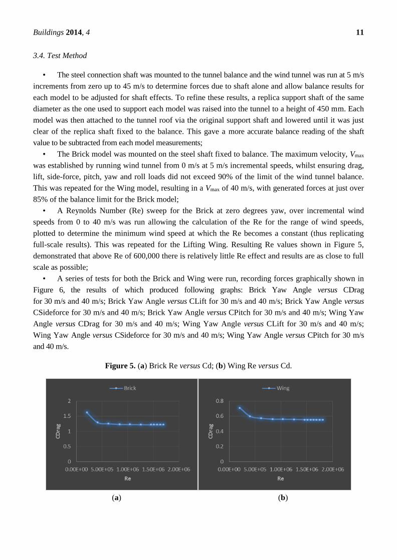
Buildings 2014, 4 11
3.4. Test Method
• The steel connection shaft was mounted to the tunnel balance and the wind tunnel was run at 5 m/s
increments from zero up to 45 m/s to determine forces due to shaft alone and allow balance results for
each model to be adjusted for shaft effects. To refine these results, a replica support shaft of the same
diameter as the one used to support each model was raised into the tunnel to a height of 450 mm. Each
model was then attached to the tunnel roof via the original support shaft and lowered until it was just
clear of the replica shaft fixed to the balance. This gave a more accurate balance reading of the shaft
value to be subtracted from each model measurements;
• The Brick model was mounted on the steel shaft fixed to balance. The maximum velocity, Vmax
was established by running wind tunnel from 0 m/s at 5 m/s incremental speeds, whilst ensuring drag,
lift, side-force, pitch, yaw and roll loads did not exceed 90% of the limit of the wind tunnel balance.
This was repeated for the Wing model, resulting in a Vmax of 40 m/s, with generated forces at just over
85% of the balance limit for the Brick model;
• A Reynolds Number (Re) sweep for the Brick at zero degrees yaw, over incremental wind
speeds from 0 to 40 m/s was run allowing the calculation of the Re for the range of wind speeds,
plotted to determine the minimum wind speed at which the Re becomes a constant (thus replicating
full-scale results). This was repeated for the Lifting Wing. Resulting Re values shown in Figure 5,
demonstrated that above Re of 600,000 there is relatively little Re effect and results are as close to full
scale as possible;
• A series of tests for both the Brick and Wing were run, recording forces graphically shown in
Figure 6, the results of which produced following graphs: Brick Yaw Angle versus CDrag
for 30 m/s and 40 m/s; Brick Yaw Angle versus CLift for 30 m/s and 40 m/s; Brick Yaw Angle versus
CSideforce for 30 m/s and 40 m/s; Brick Yaw Angle versus CPitch for 30 m/s and 40 m/s; Wing Yaw
Angle versus CDrag for 30 m/s and 40 m/s; Wing Yaw Angle versus CLift for 30 m/s and 40 m/s;
Wing Yaw Angle versus CSideforce for 30 m/s and 40 m/s; Wing Yaw Angle versus CPitch for 30 m/s
and 40 m/s.
Figure 5. (a) Brick Re versus Cd; (b) Wing Re versus Cd.
(a) (b)

Buildings 2014, 4 12
Figure 6. Wind force coefficients on the Lifting Wing.
3.5. Test Results
An overlay of the two crucial sets of results for the Wing and Brick Yaw Angles versus CDrag
at 30 m/s and 40 m/s, and the Wing and Brick Yaw Angles verses CLift at 30 m/s and 40 m/s were
graphically plotted, shown in Figure 7a,b.
The primary conclusions drawn from the CDrag overlay of the Wing and Brick are:
• The Wing profile had a dramatically lower overall drag profile (in excess of 50% less CDrag
than that of the Brick), hence significantly less drag load would be induced on the cable and the crane,
in all wind conditions;
• The Brick results plotted graphically exhibit a deep V, which shows a relatively large
sensitivity to wind direction changes, which dramatically increase drag- and swing-induced loading,
hence load on the crane. This feature is shown by comparing flow visualisation Figure 8a at zero
degrees showing a wide flow attachment line one third back from the nose and Figure 8b at 10 degree
offset, showing a more defined flow attachment line further forward, directly behind the front corner.
This increases the size of the wake area and reverse flow behind the Brick, thereby increasing drag;
• By comparison, the Wing plotted results exhibit a smooth, shallow curve, showing relative
insensitivity to changes in wind direction, with less drag- and swing-induced forces, hence a more
stable flight. This is demonstrated by comparing the Brick Figure 8b and the Wing Figure 11a at
10 degree offset. This shows smooth attachment lines running to the sharp trailing edge of the Wing,
limiting the separated flow, or wake area behind the Wing, hence low drag;
• The tendency for drag to increase as yaw angle increases tails off earlier with the Wing,
reaching a maximum at around ±12° (See Figure 7a) due to the sharp trailing edge and smooth flanks,
whereas the Brick drag forces continue to increase as yaw angle increases to a maximum at around
±18° as the wake area behind the Brick and reverse flow continues to grow. This demonstrates the
improved stability generated by the Wing, reducing drag-imposed loads on the crane in higher wind
speed and with changeable wind directions.
The primary conclusions drawn from the CLift overlay of the Wing (with Brick load inside the
Wing) and Brick are:

Buildings 2014, 4 13
• Lift forces generated on both models are less than a 10th of magnitude of drag forces and
therefore its influence is likely to be less significant;
• The Wing profile has a lower overall lift profile (less than 1/4th of the lift of the Brick at higher
yaw angles) hence significantly less rise-and-fall load would be induced on the cable and crane
in higher wind conditions. This feature is most clearly demonstrated by comparing flow visualisation
Figure 9a, the leeward side of the Brick at −25°. It shows a more pronounced flow along the top
and bottom edges, which become more dominant at the higher yaw angle. In contrast, the Wing
(Figure 12a) shows the leeward side of the Wing at −10° (which was almost identical to the
Wing at −25°). The Wing shows more fractured, multiple flow separation lines running from the
nose toward the tail that drop away much earlier. These markedly differing flow features would
explain the differing lift forces generated on each model;
• The Brick exhibits a sharp and deep W profile, which signifies sensitivity of this shape to
increasing wind yaw angle, dramatically increasing lift- and fall-induced loading, hence load on
the crane. This would result in a rotation of the load when freely suspended from a crane,
causing safety issues when trying to fly and land the load safely;
• The Brick also shows increasing sensitivity to higher wind speed as the results for 30 m/s and 40 m/s
diverge at higher yaw angles producing unstable flight characteristics as these factors increase;
• By contrast, the Wing exhibits a smooth, shallow curve, showing relative insensitivity to changes
in wind yaw angle or wind speed, hence less rise- and fall-induced forces and more stable flight
characteristics.
Figure 7. (a) Wing and Brick Yaw Angles versus CDrag for 30 m/s and 40 m/s; (b) Wing
and Brick Yaw Angles versus CLift for 30 m/s and 40 m/s.
0.4
0.6
0.8
1
1.2
1.4
-30 -20 -10 0 10 20 30
CDRA
G
YAW ANGLE (DEGREES)
Wing 30m/s Wing 40m/s Brick 30m/s Brick 40m/s
(a)
0
0.02
0.04
0.06
0.08
0.1
0.12
0.14
0.16
0.18
0.2
-30 -20 -10 0 10 20 30
C LI
FT
YAW ANGLE (DEGREES)
Wing 30m/s Wing 40m/s Brick 30m/s Brick 40m/s
(b)

Buildings 2014, 4 14
3.6. Wind Tunnel Test Conclusion
Each of these tests were run twice and results showed good repeatability of generated quantitative
data for both model’s drag and lift forces at varying degrees of yaw and wind speeds. The arithmetic
mean was taken to give the central tendency as there were no outlier results taken (all values were
within 5% of the initial the result). Side force and pitching moment were also measured in this method,
but ultimately deemed less critical, being relatively similar for both models, with slightly less pitching
moment generated by the Wing under extreme yaw angles and slightly higher side forces generated by
the Wing at higher yaw angles, creating a restoring yawing moment (self-correcting characteristic),
ultimately producing a stable flight in changing wind direction. These mean results demonstrated
significantly improved aerodynamic characteristics of the Wing, resulting in significant reductions in
critical forces generated by wind acting on the Wing, hence forces imposed on the tower crane at full
scale. These results point toward the Wing assisting the tower crane operator in their control of the
tower crane in higher wind-speed conditions experienced on a construction site, thereby delaying his
decision to take the crane out of service at a wind speed significantly lower that the manufacturers
prescribed “out of service” speed.
These conclusions were further tested by conducting flow visualisation analysis of the Wing and
Brick at varying wind speeds and yaw angles in the wind tunnel, discussed below.
3.7. Flow Visualisation
A series of flow visualisation photographs of the Brick and Wing models were taken at key stages
in the wind tunnel testing for each model to allow comparison of aerodynamic flow around the models.
These were achieved by coating the Brick and Wing models with a mixture of titanium dioxide,
paraffin and linseed oil, and capturing the resultant flows at true zero degrees, plus and minus 10° and plus
and minus 25° yaw at varying wind speeds. A demonstrative selection of flow images are given in
Figures 8–12. Wind is flowing from left to right in all figures with exception of 11a,b, where it is right
to left. Windward is a (+) yaw angle from true zero (head-to-wind flow), showing the side facing into
the wind and leeward a (−) yaw angle showing the side in the wind “shadow”.
Figure 8a is a flow visualisation photograph of the Brick at true zero to the wind flow and is viewed
from the leading edge corner. The wind flow impacts on the flat face and spreads out towards all four
sides of the Brick. The flow separates at the four edges and a large wake is formed behind the Brick.
This wake is responsible for the large coefficient of drag seen in the wind test results. The wide flow
separation line running from the top to bottom of the Brick at the point where the vortices at each side
of the Brick, created by the blunt nose, reverse the flow back toward the front of the Brick where it
meets the wind flow spilling around the nose corner and become entrained in the wake. This causes the
flow to stall and gravity then drags the mixture down. These flow patterns should occur on all four
sides (excepting gravitational effect).
Figure 8b, taken from the same position, but with the Brick at +10° yaw (windward), shows the
reverse flow separation line being pushed much nearer the front corner of the nose. This is caused by a
more dramatic meeting of the vortex flow (which has increased force due to the +10° yaw) and the
frontal flow spilling around the nose corner. It also shows flow detachment approximately mid-way

Buildings 2014, 4 15
along the Brick, with some flow being pushed toward the nose and some being pushed toward the rear
of the Brick.
Figure 8. (a) Brick at 0°, 40 m/s; (b) Brick at +10°, 40 m/s.
(a) (b)
Figure 9a shows the leeward side of the Brick at −25° yaw. There is more pronounced flow along
the top and bottom edges, which becomes more dominant at the higher offset angle. The flow has
separated at the edge on the front face, but the reverse flow is now three dimensional, flowing towards
both the front and side edges. The flow towards the sides meets flow spilling around from the top and
separates at the white line and is entrained into the wake. The separation line at the lower edge is
smaller due to gravity. This will contribute to the lift force seen in wind test results. The resulting wake
will be more pronounced on this side.
Figure 9b shows the windward side of the Brick at +25° yaw. The flow is pushing from the front
centre in three dimensions toward the top, bottom and rear trailing edges remaining attached along the
flank. The resulting wake will be less pronounced on this side.
Figure 9. (a) Brick nose at −25°, 40 m/s; (b) Brick tail at +25°, 40 m/s.
(a) (b)
Figure 10a shows the Lifting Wing model at 0°. The Wing has a very low aspect ratio and the flow
around the trailing edge is highly significant. The extent of the separated flow producing the wake is
much smaller than for the Brick, resulting in a significantly lower drag. The flow is attached from the
nose and forms two strong flow separation lines running from the nose toward the tail.
These drop away toward the bottom rail at the tail of the Wing as flow rate reduces and gravitational
forces take over. The collection of mixture at approximately one third along from the nose of the Wing

Buildings 2014, 4 16
is at its widest point. This may indicate a nearing of flow separation at this potential transition point,
but the flow successfully negotiates the curve of the Wing and continues in laminar flow along the
Wing’s surface until it nears the tail’s trailing edge.
Figure 10b shows this effect from the tail view. It shows the flow reducing as it runs along the
Wing and gradually falling under gravitational force as it nears the narrowest point, the trailing edge.
It then separates, creating a relatively small wake.
Figure 10. (a) Wing nose at 0°, 40 m/s; (b) Wing tail at 0°, 40 m/s.
(a) (b)
Figure 11a shows the Wing at +10° yaw, where it exhibits a more singular flow separation line
running from the nose toward the tail. This drops away more gradually, only hitting the bottom rail at
the tail intersection point. The collection of mixture has moved further back from the nose of the Wing
and is now behind the point of maximum Wing width. This indicates the potential transition point has
moved further back due to the increased windward yaw angle, hence increased flow across this face of
the Wing. Again, it does not actually separate at this point and continues toward the tail in laminar
flow until it nears the tail trailing edge, but at a point further from the tail, indicating that the turbulent
boundary layer is occurring earlier. The flow patterns are very similar to the 0° case which explains
why the drag appears to be relatively invariant for the Wing.
Figure 11b shows this effect from the tail view and shows the flow reducing and falling under
gravitational force as it travels to the trailing edge, but that it separates earlier to become turbulent flow.
Figure 11. (a) Wing nose at +10°, 40 m/s; (b) Wing tail at +10°, 40 m/s.
(a) (b)
Figure 12a shows the Wing at −10° yaw, leeward side viewed from the nose. The Wing now
exhibits more fractured, multiple flow separation lines running from the nose toward the tail that drop

Buildings 2014, 4 17
away much earlier, demonstrating that the flow rate is much reduced across this face and gravitational
forces take over earlier. The collection of mixture has moved further toward the nose and is now in
front of the maximum Wing width position. This indicates the transition point has moved forward due
to the more turbulent, reduced flow formed in the wind shadow. It now actually begins to partially
separate at this point, whilst some flow does continue toward the tail in laminar flow but then separates
at a point much closer to the midpoint of the Wing, indicating that the turbulent boundary layer is
occurring much earlier. This effect would create the restoring turning moment in the Wing, ensuring it
returns to a zero yaw position (nose-to-wind).
Figure 12b is the tail view and shows the flow reducing and falling under gravitational force much
earlier as it travels along the Wing and separates earlier to become turbulent flow across the rear third
of the Wing.
Flow visualisation pictures of the Wing at ±25° yaw showed no significantly differing patterns to
the ±10° discussed above. This fact demonstrates that the drag is relatively invariant for the Wing,
whilst exhibiting significantly less drag variation than the Brick.
Figure 12. (a) Wing nose at −10°, 40 m/s; (b) Wing tail at −10°, 40 m/s.
(a) (b)
3.8. Flow Visualisation Conclusion
These flow visualisations show a relatively clean, stable flow over the Wing at varying degrees of
yaw, demonstrating stable and predictable aerodynamic behaviour. The significantly reduced drag of
the Wing compared to the Brick, along with the Wing’s invariance of drag at higher yaw angle, are the
key factors in proving the ability of the Wing to operate safely in higher and gustier wind conditions
than a standard construction load. These observations correlate with the quantitative data taken during
wind tunnel testing and reinforce the characteristics of stable and improved aerodynamic behaviour of
the Wing over the Brick. These results were further tested by conducting a dynamic test of the Wing
suspended in the wind tunnel.
3.9. Preliminary Dynamic Test
The objective of this dynamic test was to conduct visual analysis of the Wing’s aerodynamic
characteristics under conditions reflecting, as closely as possible, suspension of the Wing from a
tower crane cable in wind conditions likely to be experienced on a tall building site. No

Buildings 2014, 4 18
quantitative measurements could be taken during this test, as it was purely a visual analysis of the
Wing’s aerodynamic performance.
It was noted during this test that error in model symmetry and the inability to finitely level the
model affected the results and would need further refinement to achieve an accurate replication of
full-scale results.
The Wing model was freely suspended by three, 2 mm in diameter multi-strand steel cables, each
with a 10 kg breaking strain. These were mechanically fixed to the top edge of the model, one directly
above the centre of the nose and two equally positioned on the top edge either side of the Wing, behind
the widest section of the Wing. The centre line of the three wires were over the centre of gravity of the
model. These wires were sufficiently long to allow the Wing to be suspended in the centre of the
tunnel working section, with the wires running through a hole in the roof of the tunnel and
mechanically fixed externally to support the dead and live loads of the model during testing
(Figure 13a). This suspension method replicates the envisaged method of suspension of the full-scale
Wing from a tower crane.
A series of videos were taken to record the behaviour of the Wing under increasing wind speeds
from 0–12 m/s. These tests were then repeated with loads added inside the Wing (1 kg metal plates
fixed inside the wing profile) to replicate 1, 2 and 3 tonne loads on a full-scale Wing (Figure 13b).
Observations were made on Wing stability and flight behaviour from the side and roof windows of the
tunnel working section.
Figure 13. (a) Wing Suspended for Dynamic Test; (b) Wing with Internal Load.
(a) (b)
3.10. Dynamic Test Observations
The test was initially run with no internal load and videoed from the side window of the tunnel.
The Wing remained relatively static as the wind speed was increased from 0 m/s to 9 m/s, swinging

Buildings 2014, 4 19
slowly back by approximately 5° from the vertical as wind speed increased to 9 m/s. At 10 m/s the
nose of the Wing was observed to begin to move horizontally from left to right, stop and then return
from right to left through the head-to-wind at 0° yaw. This repeating oscillation increased in yaw angle
as the wind speed was increase to a maximum of 12 m/s, whereupon the nose of the model, viewed
from above, moved left to right whilst swinging forward and back, describing a repeating infinity (∞)
symbol movement over a distance approximately equal to half the length of the model (300 mm). This
oscillation reduced as the wind speed was reduced to 9 m/s, whereupon the model became relatively
static again, holding the 5° inclined position.
This test was repeated with a load of 2 kg fixed inside the Wing. It repeated the pattern of the first
test, with the exception that the oscillation began at the increased wind speed of 11 m/s and diminished
as the wind speed was reduced below 11 m/s.
Finally, a load of 3 kg was fixed inside the Wing, again repeating the pattern of the first and second
tests, with the exception that the oscillation began at an increased wind speed of 12 m/s and diminished
when wind speed was reduced below 12 m/s.
The initial movement of the nose from left to right was deemed to be caused by a lack of absolute
symmetry of the model and it being slightly out of level horizontally due to unequal lengths of its three
suspension cables. These small errors create a gradually increasing turning moment on the model as
the wind speed increases. However, this also demonstrates the Wing’s self-correcting characteristic,
producing stability of flight at full scale, as this would ensure a slowly correcting nose-to-wind
position of the Wing, desirable in changeable, gusty wind conditions typified on congested city-centre
tall building sites.
3.11. Implications of Results on Wing Design
This preliminary dynamic test demonstrated that the full-scale Lifting Wing would need to be
made symmetrically, ideally utilising vacuumed formed thermoplastic technology or moulded
carbon-fibre-reinforced polymer, plastic or thermoplastic giving the added benefits of a higher
strength-to-weight ratio and greater ability to withstand impact deformation. Residual error could be
corrected by adding a top mounted vertical stabilising fin, fixed above the trailing edge of the Wing. The
dynamic test also demonstrated the need for finite adjustment of suspension cables to ensure truly level
flight. Following this paper’s publication, this dynamic test will be further refined by the introduction
of turnbuckles on each of the three suspension wires above the tunnel, allowing finite adjustment of
each cable length, and hence achieving true horizontal suspension of the model in the tunnel.
This test also demonstrated the proportional relationship of increasing load to more stable
flight—the greater the load carried inside the Wing, the less effect the non-symmetrical features of the
model had on the stability of the flight in increased wind speed. It also proved that the ultimate wind
speed in which stable flight could be achieved would be directly related to the size of the load carried
inside the Wing.
4. Overall Conclusions
The wind tunnel test quantitative data correlates with the flow visualisation and preliminary
dynamic test observations. These reinforce the primary Wing characteristics of reduced drag in excess

Buildings 2014, 4 20
of 50% lower than the Brick and of side forces on the Wing creating a restoring moment when flying
in changeable wind direction conditions, giving a desirable nose-to-wind behaviour. These key
characteristics combine to reduce induced loads on the tower crane and produce stable improved
aerodynamic behaviour of the Wing when compared to typical construction loads.
This demonstrates that the Wing achieves its primary purpose of increasing the ability to lift
construction materials safely in higher and more gusty wind-speed conditions than is currently
achievable. Therefore, the Lifting Wing design, if used on a tower crane of a tall building, should
create a valuable contribution in mitigating the effect of wind causing critical path delay during the
construction of a tall building, potentially reaping substantial time and cost savings. This knowledge
and benefit could be transferable internationally as, without exception, tall buildings across the world
are built using tower cranes which are negatively affected by wind during the build period, delaying
completion, frustrating builders from completing on time and budget and ultimately, owners from
occupying their new tall buildings. These positive results will be further demonstrated by future studies
utilising a full-scale Lifting Wing on a tower crane, discussed in the following section.
5. Further Work
Following running the refined dynamic test discussed above, the final stage of the Wing
development will be undertaken with assistance from the authors’ sponsoring company involving the
construction of a full-scale Wing and its dynamic testing utilising a Saddle Jib or Luffing Jib Tower
Crane. In this test, an experienced tower crane operator will lift a rectangular “Brick”-shaped reference
load in wind conditions approaching industry-recognised winding-off speeds. The load will then be
placed inside the full-scale Wing and lifted in the same wind conditions. The operator will note flight
characteristics of each lift and determine the increased wind speed in which the Wing can still be lifted
safely. This qualitative analysis will rely on the feedback from the operator, rather than on any
measured force data. However it is exactly this operator analysis that is used across the industry to
determine the safe limit of lifting by cranes on every site the world over. If tower crane operators feel
the Wing allows extended lifting in higher wind conditions, then it will have succeeded.
An international patent has been applied for covering the Lifting Wing and the research that has been
undertaken to date.
Author Contributions
This paper describes an element of the doctoral research conducted at Loughborough University in
partnership with Lend Lease for the award of Engineering Doctorate. Ian Skelton was the Research
Engineer and undertook the majority of the primary work. The co-authors of this paper are the EngD
supervisory team, augmented as the project progressed due to staff movements. All supervisors
contributed to manuscripts as the paper was being developed and reviewed. Peter Demian was the
principal supervisor from the beginning of the project. Jacqui Glass was the second supervisor at
Loughborough University at the time the experiments for this paper were conducted and the paper was
written. Dino Bouchlaghem and Chimay Anumba were supervisors during their time at Loughborough
University, and remained active contributors after moving to other organisations.

Buildings 2014, 4 21
Conflicts of Interest
The authors declare there are no conflicts of interest.
References
1. Allen, J.E.E. Aerodynamics. The Science of Air in Motion; University of Michigan: Michigan City,
MI, USA, 1999; pp. 83–85.
2. Anderson, J. Fundamentals of Aerodynamics; McGraw-Hill: New York, NY, USA, 2010;
pp. 23–24.
3. Barlow, J.B.; Rae, W.H.; Pope, A. Low Speed Wind Tunnel Testing; Wiley-Interscience:
Ann Arbor, MI, USA, 1999; pp. 143–149.
4. Baker, W.F. S.O.M. Structural Engineering Partner. In Proceedings of the World’s Tallest
Building, Burj Dubai, UAE, Seoul, Korea, 10–14 October 2004.
5. Construction Plant Hire Association (CPA). Tower Crane Interests Group and Health & Safety
Executive the Tower Crane Operator’s Handbook; HSE: London, UK, 2008; pp. 27–28.
6. Drela, M. XFOIL: An Analysis and Design System for Low Reynolds Number Airfoils; Springer:
Berlin/Heidelberg, Germany, 1989.
7. Dole, C.E.; Lewis, J.E. Flight Theory and Aerodynamics: A Practical Guide for Operational
Safety; John Wiley & Sons: New York, NY, USA, 2000; p. 351.
8. International Standard ISO 4302-1981. Cranes—Wind Load Assessment. Available online:
http://www.iso.org/iso/home/store/catalogue_ics/catalogue_detail_ics.htm?csnumber=10156
(accessed on 16 May 2014).
9. Kermode, A.; Philpot, D.R.; Barnard, R.H. Mechanics of Flight; Prentice Hall: London, UK, 2012.
10. Morby, A. Dreaming Spires for the Towering Giants. Available online: http://www.cnplus.
co.uk/news/dreaming-spires-for-the-towering-giants/893729.article (accessed on 23 May 2014).
11. OSHA. 1999. Big Blue Crane. Video by Occupational Safety & Health Administration safety
inspector on site the day of the collapse. Available online: http://www.osha.gov/video/
bigblue.wmv (accessed on 25 November 2013).
12. Ross, B.; McDonald, B.; Vijay Saraf, S.E. Big Blue Goes Down. The Miller Park Crane Accident.
Eng. Fail. Anal. 2006, 14, 942–961.
13. Riewestahl, B. Lampson Transi-Lift “Big Blue” Crane Collapse E.I.T., M.S., Penn State, 2010.
Available online: https://www.youtube.com/watch?v=zRvQlEbJnqc (accessed on 23 May 2014).
14. Rosenfeld, Y.; Shapira, A. Automation of existing tower cranes: Economic and technological
feasibility. Autom. Constr. 1998, 7, 285–298.
15. Shapria, M.; Lucko, G.; Schexnayder, C. Cranes for Building Construction Projects. J. Constr.
Eng. Manag. 2007, 133, 690–700.
16. Shiffler, D.A. Crane City. Am. Cranes Transp. 2012, 2, 21–25.
17. Skelton, I.; Demian, P.; Bouchlaghem, D. Britain’s tall building boom: Now bust? Proc. Inst. Civ.
Eng. Struct. Build. 2009, 162, 161–168.

Buildings 2014, 4 22
18. Skelton, I.; Demian, P.; Bouchlaghem, D.; Anumba, C. The State-of-the-art of Building Tall.
Challenges, Opportunities and Solutions in Structural Engineering and Construction; Taylor &
Francis Group: London, UK, 2010.
© 2014 by the authors; licensee MDPI, Basel, Switzerland. This article is an open access article
distributed under the terms and conditions of the Creative Commons Attribution license
(http://creativecommons.org/licenses/by/3.0/).

___________________________________________________________________________
APPENDIX D
APPENDIX D BUSINESS MARKET REVIEW

UK Tall Building Market Sector Report - An Overview of the Market and its
Forecast to 2012 (May 2007)
Defining a Tall Building in the UK
This research focuses on tall buildings in the UK as being between twenty to sixty stories, circa 80 – 300m
(depending on whether the building has commercial or residential floor to floor heights). A good definition of a
tall building in town planning terms is one which stands above the prevailing skyline. A good construction
definition is a building which has technical and design differentiation from its neighbours. Even with modern
build methods, above twenty stories a building becomes technically distinct in its structure, services, vertical
circulation, life safety and cost. This is why they deserve a different classification – the UK tall building.
Research undertaken for this review shows that of the fifty eight current UK tall buildings currently proposed,
almost 70% are in London. This report therefore focuses on London, but does consider the South East and Other
Regions.
London High Rise = Global Mid Rise
London’s skyline is predominantly low rise with distinct pockets of medium to high rise, planned to allow space
for the protected St Paul’s Cathedral sight lines from strategic London viewpoints (Planning Act 1990). A tall
building in the London context is considered to be twenty to sixty storeys. At the top end of the London scale are
London Bridge Tower (the Shard) and The Bishopsgate Tower topping 300m and containing more than eighty
storeys. The lower end of the London scale is dictated by the need at this height for technological changes to the
way buildings are constructed, utilising tall building techniques as opposed to low rise construction techniques.
New York City is widely recognised as one of London’s main competitors for the status of financial centre of the
world. Its skyline, in comparison to London, is predominantly medium rise with widespread pockets of high rise.
A tall building (skyscraper) here is deemed to be thirty to one hundred plus stories (although local fire codes
change at fifteen storeys). In the last six years America’s appetite for commercial tall buildings has cooled, but
residential demand remains strong and international developments are beginning to influence corporate decision-
making in New York, especially regarding sustainable design. The future of the skyscraper seems assured in
New York City, even after the loss of nearly three thousand lives in the Twin Towers disaster of Manhattan.
Manhattan has showed resilience as a business location, according to recent research conducted for the Russell
Sage Foundation: three years after the attacks, financial firms have mostly decided to stay in Manhattan. Even
Cantor Fitzgerald, a trading firm that lost two-thirds of its employees in the collapse of the World Trade Center
towers, will move into new quarters in midtown (Fuerst 2007). These businesses, according to a recent New
York Times report, are now spending $3.8 billion annually on security and disaster contingency planning. The
key factor for financial firms influencing the decision to stay ‘in the hub’ is the importance of access to sensitive
knowledge through face-to-face interaction and a tightly woven network of personal relationships between
APPENDIX D

industry professionals, Clients, suppliers, and other decision-makers. America’s other largest cities of Chicago,
Washington and Los Angeles are also consolidating their global-hub status. The idea that businesses must cluster
‘downtown’ as they do in London had seemed ‘quaint’ in America. The assumption was that technology would
liberate workers from the inconveniences of the congested centre, but the business location decisions post 9/11
seem to disprove this.
American tall building developers and large tenants have resisted the thin ‘Euro towers’ typified by small floor
plates and bespoke cladding systems. Americans argue this form of tall building is costly and not enough people
can gather on a single floor. A design such as Swiss Re’s 30 St Mary’s Axe would not be feasible in America
due to the lower importance placed on internal spatial quality and external sculptural effect, plus the widespread
availability of large, regular shaped building plots in the US. Floor plates are deeper and more efficient in
America, where core to wall depths of 13-18m (42-60’) are standard. Due to the bigger floor space per height,
American tall buildings are financially more efficient. Less constrained sites in the UK such as Canary Wharf
allowed tall buildings to follow the American model (although on a shallower floor plate depth).
Tokyo is the second main competitor to London for the status of financial centre of the world. The skylines of
Tokyo, Hong Kong and Shanghai cities, in comparison to London’s, are predominantly high rise with isolated
pockets of low rise on the peripheries. Asia is seen as the natural environment of the very tall building. These
very tall buildings make sense where density and the urban infrastructure make it the most effective way to
occupy land. High density living is already an accepted norm in much of Asia. Towers are constantly being built
in Hong Kong, Guangzhou, and the other high-growth Asian cities. The tallest, densest Chinese buildings are
rising over rail stations, with airport access, (Willis, 2007). As the Chinese population continues with rapid
industrialisation, there is a boom in tall buildings on an unprecedented scale. China has at least sixty two, three
hundred metre buildings, or ‘supertalls’, at some level of development - there are nine in Chongqing alone,
which means it is building more 150m tall towers now than New York has ever built. This is extraordinary as
every major Chinese city is undergoing a similar scale of development in an organic and market driven manner,
rather than following the property speculation bubble model that Dubai followed. Dubai is impressive in its
construction of tall buildings, but China is growing an equivalent of ten Dubai's.
The UK tall building is therefore defined on the international stage by its more conservative height, individual
architectural approach to the internals and externals, its response to its non-regular site and the surrounding
heritage of the city-scape. This results in high quality, individualistic buildings demanding high quality building
solutions. Modularity and repetition are not seen as UK tall building traits, resulting in a more costly solution.
The Rise and Rise of Tall Buildings in London
Britain’s experience of tall buildings has long been in the shadow of post-war regeneration. The 1950’s to 1970’s
produced a swathe of local authority housing towers and brutalist office towers between ten and thirty storeys
high. The high-profile failure of these post war experiments due to weak design, detailing and construction led to
a general rejection of the high rise form in the 1980’s and a concentration on the conservation and heritage
arenas. There were a few exceptions to this rule in the first generation of tall buildings. The notably successful
APPENDIX D

tall buildings of this era have now achieved listed building status: Centrepoint (Grade II), BT Tower (Grade II)
and Trellick Tower (Grade II*).
Interest in tall buildings has risen to new heights recently, both in the commercial and residential sectors. This is
evident on the supply side, especially in London, where a pro tall building stance is notable in: The London Plan;
the number of planning proposals for tall buildings; the granting of planning consent to new proposals such as
Heron Tower, the Shard in Southwark and Columbus Tower in Tower Hamletts; the recent completion of
numerous tall buildings in various London locations including Paddington, The West End, The City and Canary
Wharf; the successful refurbishment of previous generations of tall buildings such as Tower 42 and City Point.
Signature architects are now falling over themselves to design tall buildings (Strelitz 2005).
There is now a strong City ambition to build high. Davis Langdon & Seah International believe this has grown
from Foster and Partners mould breaking design for the owner-occupied Swiss Re development, which won
support from CABE (Commission for Architecture and the Built Environment), English Heritage and the City,
all of whom were keen to secure bespoke headquarters for major commercial institutions (Morrell, 2006). The
high profile success of Swiss Re’s 30 St Mary’s Axe undoubtedly led to increasing pressure for more towers.
The Heron Tower Inquiry followed and forced the evolution of city policy, developing the concept of an
‘Eastern Cluster’ in the city, not affected by St Paul’s Cathedral Height Grid, Strategic Viewing Corridors or
Conservation Areas (Linklaters, 2002). 122 Leadenhall Building will become the focal point of this new cluster.
The rising profile of London as a ‘World City’ over the past decade (LPAC 1998), allied to the refocus of the
planning system for high density developments and brown field schemes, have assisted this growth in building
tall. London, now seen as the de-facto capital of Europe and is consolidating its position of a world leading
financial centre, second only in trade value to Frankfurt. It has desires to eclipse Frankfurt as Europe’s financial-
services capital. Some experts believe this is already happening as it has more people with more skills, depth and
expertise in one spot than any other in Europe (Duffy 2007). The London Mayor believes London is now
challenging Tokyo and New York as their only global competitor. He has repeatedly stated this must be
underpinned by the provision of world class office space and infrastructure. ‘London must continue to reach for
the skies’ (Livingstone, 2001).
Globally, property has enjoyed a re-rating as an asset class and London particularly has benefited. Jones Lang
Lasalle believes London is vying with New York as the world’s premier financial centre as a result of tighter
financial regulation in the US and a growing reluctance in the Middle East to invest in America post 9/11 (Jones
Lang Lasalle Research 2006). Savills Research foresees a resurgence in institutional investment activity in
London residential stock due to its ‘more benign regulatory environment’ and the continued globalisation of
property markets. UK funds are being benchmarked against other countries where residential is already a mature
investment sector. The relatively strong and stable UK performance produced over the last ten years in
comparison to other asset classes will continue to act as a draw to more funds in the future (Savills Research,
2007).
The current suite of tall buildings being constructed in the heart of the City (Leadenhall, Shard, Gerkin, Heron,
Fenchurch St. and the Bishopsgate Tower) were all commissioned due to the threat of London Docklands on the
City’s position in the mid 1990’s. Plot ratios were relaxed to encourage development in the City. This response
APPENDIX D

to a ten year old threat is now visible on the streets even though the threat has gone as Canary Wharf is now 90%
full (McAlister, 2006). The latest development in this office turf-war between the City and the Docklands is that
of global advertising agency Ogilvy & Mather being in advanced talks to move back to central London from
Canary Wharf. They were the first tenants to move to Docklands in the late 1980s and are interested in a
refurbishment of the former GLC headquarters at County Hall (Hodgekiss, 2007). The prestige of the City seems
to be coming back into effect according to cityoffices.net, an independent property advisor to the property
market. Figure 1 shows the huge area of office space under construction in the seven sectors of London in Q4 of
2006.
Figure 1. London City Office under Construction, Q4, 2006 (cityoffices.net 2007)
Evolution of London Policy for Tall Buildings
Research shows a recent rise in public interest in tall buildings has coincided with a change in policy and the
emergence of widespread support, which has been dormant for over twenty years. Tall building-proactive policy
changes include:
0100,000200,000300,000400,000500,000600,000700,000
Sq m Being Built
City
City
Frin
ge
Dockla
nds
Mid
Tow
n
Sout
hbank
Wes
t End
Wes
t End
Frin
ge
London City Sectors
London Offices Under Construction, Q4 2006
City 606,929 sqm - ( 6,532,932 sq ft )
City Fringe 54,440 sqm - ( 585,988 sq ft )
Docklands 32,516 sqm - ( 349,999 sq ft )
Mid Town 7,838 sqm - ( 84,368 sq ft )
Southbank 88,884 sqm - ( 956,740 sq ft )
West End 254,262 sqm - ( 2,736,855 sq ft )
West End Fringe 67,351 sqm - ( 724,960 sq ft )
APPENDIX D

Central Government now believes that tall buildings meet with their current focus on sustainable
development, satisfy their urban renaissance requirements of increased density and could help toward
the reduction of private car commuting, thereby assisting with the ‘Kyoto Objectives’.
The Government has stated that ‘high rise buildings generally require smaller sites than low rise
buildings with big floor plates offering an equivalent amount of space’ (Linklaters, 2002).
The Government recently encouraged local councils to generate proactive policies toward tall buildings
and identify suitable and non-suitable sites in their local plans.
The Government’s support of tall buildings has been proven recently with the Deputy Prime Ministers
approval of planning consent for London Bridge Tower and Heron Tower.
The Government re-established a strategic planning authority for London in 2000. The GLA superseded
the London Planning Committee in 2000 and published the London Plan in February 2004: ‘London
must cater for its projected population growth to 8.1 million people by 2016, with 636,000 new jobs
being created over this period in order to maintain its status as a Global City. It must do this without
sacrificing London’s open spaces and green belt. To achieve this objective, tall buildings are identified
as mechanisms to facilitate increased densities at locations with good public transport’ (GLA, 2004).
All London Authorities are now required to bring their local plans into broad compliance with the
Mayor’s London Plan (Strelitz, 2005).
New powers were granted to the Major of London in July 2006, which allow the Mayor to approve
‘strategic’ planning applications, although ministers have yet to fully define the meaning of ‘strategic’.
The Mayor will also be able to override local consultations on planning policies and order boroughs to
conform to his planning priorities.
Many London Local Authorities are now actively supportive of tall buildings, arguing that they promote
economic development (such as Corporation of London, Westminster and London Boroughs of
Southwark, Croydon and Hackney.
The Mayor advised ‘there are only a limited number of strategic locations where tall buildings are
viable and there are strict guidelines which developers and planners must meet. Tall buildings are likely
to be built in small clusters, like Canary Wharf, where the surrounding infrastructure can support them’
(Bar Hilley, 2006).
The Commission for Architecture and the Built Environment (CABE) replaced the Royal Fine Arts
Commission in 1999. CABE is a non-statutory planning consultee that champions quality architecture
and urban design. It published jointly with English Heritage (also a statutory consultee) the ‘Guidance
on Tall Buildings’ in 2003 which forms part of the policy that tall building proposals are judged against.
Together they have backed tall buildings deemed to be in ‘the appropriate site and achieving
architectural, urban and economic benefit’. (CABE 2003). In January 2007, CABE and English
Heritage published a consultation draft of their newly-updated Guidance on Tall Buildings, which has
been updated to reflect changes to the planning system and the experiences CABE and English Heritage
APPENDIX D

have had in evaluating planning applications for tall buildings. Additionally, CABE publicly backed the
proposed 20 Fenchurch St on the eve of its public hearing, stating it is a fine investment in architecture,
a world class design and changes its environment for the better.
The most potentially damaging recent development for tall buildings was the replacement of John
Prescott as Secretary of State at the Department of Communities and Local Government in October
2006. This caused problems for the tall building as his replacement, Ruth Kelly, rejected planning
permission for Rafael Vinoly’s Fenchurch St Tower and Ian Simpson’s Brunswick Tower as her first
move in office. English Heritage had not asked for an inquiry on either tower and the developer, Land
Securities, believed John Prescott would have approved the shorter 20 Fenchurch St proposal. This
change of stance may be due in part to the comments made by UNESCO Inspection Team about the
unsuitability of oversized developments adjacent to the World Heritage sites of Liverpool’s docklands
and The Tower of London (Dorrell, 2006). The Government is currently undertaking a study to
determine if these strategic viewpoints need more protection against tall buildings – this will potentially
be at odds with the London Plan and cause further debate. Fortunately for the tall building market,
Kelly has been recently replaced by Hazel Blears, who appears to have a more tolerant tall building
approach, although this may be tempered by her calling in of Lambeth’s 140m high Doon Street Towers
in October 2007 in response to English Heritage and CABE’s concerns over sight lines.
Who’s Driving Demand for London Tall Buildings?
Two distinct occupiers of tall office buildings in London have been identified by previous research and are
driving demand for two types of tall buildings (LPR, 2001 & Insignia Richard Ellis Research, 2002). However,
this research has identified two additional occupiers:
The first is large corporations relocating to a single building requiring ‘fat’ towers with floor plates of 3000m2
gross and up to 50000m2 total area. Their relocations are planned amalgamations of various operations, creation
of synergies between business units and to reduce facilities management costs. Examples are HSBC, Citygroup,
and Barclays, who moved to Canary Wharf as it offered the right mix of floor plate, quality of space, size and
critical mass of complementary businesses. These type of offices are now achieving an average rent of £70 per
sq ft across the seven London fringes (EGi, 2007).
The second is small international companies demanding a prestige location in multi-tenanted tall ‘iconic’
buildings. Their floor plate requirement is between 1500 – 2000m2 gross. They value prestige, high quality
shared facilities and opportunities for interrelations with neighbouring businesses. This is shown by low vacancy
rates and high rental yields. These types of offices are now regularly achieving £100 per sq ft across London, a
new record set during the second quarter of 2006 (EGi, 2007).
A third, emerging tall building market is the mixed use tower, incorporating residential, retail, office and hotel.
This form shows signs of increasing its high density tall building market share. These schemes can be inherently
efficient with complimentary structural requirements and heating and cooling shares between different
occupiers’ systems. (McAlister, 2006). This specialist tall building is discussed further in this review under
‘Mixed Use Comes of Age’.
The fourth tall building demand is the residential market, reviewed separately in this report.
APPENDIX D

Based on the research undertaken for this report, the current tall building market split for London is 54%
commercial towers (fat and iconic), 28% residential towers and 18% mixed use towers, shown graphically in
Figure 2.
Figure 2.
London’s Proposed Tall Building Demand.
The sum of these four markets means that London’s demand for tall buildings is at an unprecedented level.
Sixteen of the twenty six tallest structures in London are currently in the detailed design or construction phase
(Morrell, 2006). Additional delivery pressure is being brought by the looming 2012 Olympics, which forms a
small part of the construction planned in and around the capital constituting £5 billion of the £20 billion
estimated budget. The Olympics has become an artificial deadline for a large number of projects, which causes
consolidation of work (Thompson, 2006). This has proven to be the case with a number of tall buildings
currently being worked on with Bovis Lend Lease. There is concern that these large projects running
concurrently with the Olympics will overheat the construction market, creating local shortages of skilled labour
and materials, forcing up prices by a factor of 20% for steel reinforcement and concrete costs according to EC
Harris. Davis Langdon’s Market Forecast Report for 2007 summarises that the top and bottom of London’s
market is polarising, whereby large projects are suffering from greater inflationary pressures, while smaller
schemes retain a more competitive edge (Fordham, 2007).
Tall Commercial and Mixed Use Demand
Demand for tall buildings will be bolstered by the recent sale of 30 St Mary’s Axe, Swiss Re’s 41 storey tower,
which set a record for a UK office at £600m, bought by UK investment bank Evans Randell and German fund
manager IVG Immobilien, realising a profit of circa £250m for Swiss Re (even though it is famously inefficient
as an office with only 60% net lettable area). This sale was rapidly followed in the property press by Tishman’s
potential sale of the 36 storey City Point Tower at £650m and HSBC’s sale and lease back of its docklands tower
at circa £800m. The latest in these tall building purchases was in early March 2007, when Arab Investments Ltd
purchased the rights to the proposed 288 metre tall Bishopsgate Tower from DIFA for £200 million. The record
profits made by these sales are good omens for the continued demand for tall buildings as a profitable
investment.
London's Proposed Tall Buildings
18%
36%18%
28%
Office (Fat)
Office (Iconic)
Mixed Use
Residential
APPENDIX D

EGi, the independent research consultants and owner of The London Office Database are forecasting a flurry of
further property deals throughout 2007 as property companies that have delayed signing until after the
introduction of Real Estate Investment Trusts (REITs) now complete. Many property companies have
themselves become REIT’s to maximise tax advantages, British Land amongst the first batch. These deals
reinforce the commercial property boom which started early in 2005. King Sturge’s Head of Research reports the
amount of foreign finance looking to invest in London is unprecedented – ‘as if people are not so much investing
in London, as buying London’ (Independent 2007). King Sturge put the 2006 investment in the City alone, not
including the Docklands and West End as £8.5billion, up from £6billion in 2005.
Jones Lang Lasalle record the volume of office space taken up by new occupiers rose by 1.1million sq ft, an
increase of 35% from 2005 to 2006. This is the highest rate of growth since 2000 in the City. Rental rates in the
City grew by 20%, in 2006 but the West End grew 27% driven by banks, investment houses, private equity and
professional services firms expanding and regularly exceeding the £100 per sq ft barrier (Cityoffices.net 19-01-
2007). Vacancy rates have dropped from 18% in 2005 to 3-4% in 2007. They forecast another three or so years
of 10% growth in the London office market assisted by ‘the London growth storey’, the transparent market and
relatively long leases offered.
Savills Commercial Research Ltd summed up 2006 by publishing investment returns for the year on offices as
23% against 17% in industrial and 15% in retail. They expect the strong office performance to continue driven
by rising demand and falling vacancy rates across London and the South East which will push the regional cities
to make significant progress.
This is reflected by predictions made by Davis Langdon at the February Economic Forecasting Conference.
They stated the that 40% of all new orders placed in the UK in the last 9 months (from May 06 - Feb 07) were
for London offices, driven by the availability of London floor space dropping below demand. This has created a
two to three year window before there is a return to an overhang (supply of office space exceeding demand).
This gives ‘an unprecedented development portfolio in terms of scale, with many of these schemes to be towers’
(Rawlinson, 2007). This sharp increase in quantity of office space commencing construction is shown in Figure
3, with over 100, 000 m2 started in the City in Q4 of 2006, the highest in the last six years. Figure 3 also shows
the growth profile, or trend, since 2003.
APPENDIX D

Figure 3. City Office Construction Starts for Jan 07. (Estates Gazette, ECi, London Office Database).
Tall Residential Demand
The renaissance of tall residential buildings is due to increasing house prices outstripping build cost inflation and
the rising profile of ‘city living’ as a desirable lifestyle. This has led to a relatively new phenomenon of a price
premium relative to the height of the development. Residential property in London is some of the most
expensive in the world, with the record being taken in March 2007 by the luxury Candy & Candy development,
One Hyde Park. It is a high density four block by twelve storey scheme, which achieved £4200 per sq ft when
the first penthouse sold for £100m. (The Times January 2007). The writer subsequently won the fit out contract
for this Penthouse at £35m, making it the most expensive home per square foot in the world. In the lower market
levels, many inner and outer London boroughs have reported values over £400 per sq ft, only achieved in top
developments in other UK cities. The increase in London’s international profile has generated a rivalry between
provincial cities, whilst a demographic shift to these cities has led to an increased demand for smaller units in
high density schemes – hence the resurgence of the tall residential building across the UK. The high rise
residential tower is now widely recognised as a rapidly developing sector (EC Harris & Knight Frank LLP,
2004).
This type of residential developments, which include high and medium density residential and regeneration
apartment buildings, have been largely forward funded by the creation of the buy-to-let market in the UK. These
developments require a significant amount of advanced funding for the necessary infrastructure, sub,
superstructures, cladding, services and fit out costs involved. The viability of these cash intensive schemes has
been improved by off-the-plan sales to buy-to-let investors, providing evidence of demand to banks and
financiers funding the project.
Q1 2
003
Q4 2
003
Q3 2
004
Q2 2
005
Q1 2
006
Q4 2
006
0
20000
40000
60000
80000
100000
120000
Sp
ac
e (
sq m
)
Period
City Office Construction Starts (Source Estates Gazette, Jan 07)
APPENDIX D

This market has become the biggest investment market in the UK generating an estimated £130 billion
investment into the private rented sector and £30 billion in ancillary services to the annual Gross Domestic
Product (Savills Research, 2007). This investment market was given a kick start by the Government in the form
of the 1988 Housing Act, giving Landlords the ability to charge market rates and regain possession of their
properties via the Assured Shorthold Tenancy Agreement. The dramatic market expansion that followed
increased again in the late 1990’s following the introduction of buy-to-let mortgages, which was at a time when
the UK house price was rising by an average of 10% per annum. This relatively new area of residential growth
has been ‘pulled’ by the general confidence in the residential sector and ‘pushed’ by the volatility and weak
performance of equities and other investment sectors since 2000 (average house prices have doubled since 2000,
resulting in increased confidence and exceptional profit growth) (Savills Research 2007).
High density residential competition in other cities in the UK has intensified as a result of London’s successes
and developers are seeing the need to differentiate their product from others – building tall is an obvious way of
attracting attention as well as potentially increasing revenue. Signpost projects of this nature have recently been
completed in Birmingham, Leeds and Manchester, Glasgow and Liverpool, as each competes for the title of the
‘UK’s Second City’ (Cityoffices.net, 2006)
Growth forecasts for in the UK residential market look positive, with Savills forecasting an average of 7% for
the UK in 2007, whilst the South East and London market will see up to 20%. They state that the housing market
is not overheated and there is no speculation-created ‘residential bubble’ to burst. This is backed up by the EC
Harris Residential Research, forecasting a UK average of 6% for 2007. Both predict a slower growth toward
2010, but caveat this with the now standard concerns of global energy crisis and any ‘spectacular’ external
market influences, offset by the net population growth through influx of immigrants and growing disposable
income trends. These experts believe the UK population has one of worlds the strongest desires to invest in
property.
The Potential Downside of Tall
Countering these positive predictions with a pessimistic tall building forecast, it could be argued that the
Skyscraper Index will come into effect in London following this ‘tall building boom’ overlaid with the current
financial market buoyancy. The author of this renowned index, Andrew Lawrence, demonstrated that
historically, increase in tall building construction follows the peak of a country’s economic cycle and will be
followed by significant economic slump (Thornton 2005). This is index is unlikely to effectively predict the UK
tall building market, however, as it was an American study based on American economic cycles and even though
it’s logic stood for the historic cycles, it unsuccessfully predicted the last two slumps (the last of which was 9/11
driven), mainly due to changing investment criteria and expectations since the index was created in 1999.
Hardening stance of the Main Contractor
In response to the high level of construction activity rising toward the end of 2006, main contractors are seen to
becoming more selective on complex or high risk projects such as tall buildings. In February 2007, Davis
APPENDIX D

Langdon reported shorter main contractor shortlists and difficulties in attracting a selection of meaningful
tenders for these project types above the £50m net trade cost figure, resulting in a number of projects being
secured at premium prices. (Fordham, 2007). Clients of these project types are now increasingly using two stage
tenders, often with a negotiated second stage to make them more attractive to main contractors. This recent
hardening of negotiating position and higher price for the main contractor is due to:
Recent consolidation of the London major project contracting market with Multiplex’s withdrawal and,
others announcing concentration on alternative market areas;
A buoyant construction market, with main contractors and specialist trade contractors at, or near full
capacity;
Rising material costs for structural frames and cladding (Fordham 2007);
Very limited number of specialist cladding contractors with the ability to undertake complex schemes;
Limited availability of good design and management resources available in the marketplace;
Client focus on large, complex mixed use projects demanding high levels of skilled management input;
Clients increasingly risk-averse stance;
Clients chasing planning consent in the City utilising signature architects to satisfy CABE and Mayor’s
Office;
Main contractor supply chain initiatives with specialist contractors have increased barriers to entry and
have set up secured turnover, hence less diversity and competition;
Main contractor’s increased use of single point negotiating with specialist trade contractors reducing
competition;
Main contractor’s hardening commercial position on the pricing of risk, profit, and higher preliminary
and overhead costs, following widespread profit write-downs over the last year.
These changes in the market give a positive outlook to the top ten tall building contractors for the forthcoming
£50m-plus projects (Bovis Lend Lease are currently ranked either one or two in the commercial market, but not
ranked in the top ten for residential, the fourth tall building market driver). Rank tables and a graphic illustration
of market position are included in the following section of this report, Figures 4, 5, 6 and 7.
The Fragmented Tall Building Construction Market and BLL’s Place Within it
The UK construction market is seen as very fragmented in comparison to other UK industries (THF, 2001). The
majority of construction companies, irrespective of size, operate as management contractors employing little
direct labour and pass on the site based work to a wide variety of sub-contractors, sub-sub-contractors and self-
employed labour (Construction Task Force, 1998). Investment in fixed assets tends to be very low, with the
exception of land banks for some builder/developers. Both Egan (as chair of Rethinking Construction) in
Accelerating Change and Latham in Trust and Money and Constructing the Team state, very few contractors
APPENDIX D

have meaningfully addressed the supply chain with formalised management and committed volume (Latham,
1993).
The resulting highly elastic, low cost delivery system that makes no demand on risk capital is the free market
response to decades of wildly fluctuating demand over time and geographical location and to the obsessive focus
on first cost as opposed to running cost, reliability, quality and other manufacturing industry mantras. The better
organised medium / large building companies are close to the ideal ‘virtual company’, employing few
construction workers of their own, operating in numerous locations which change quickly in response to
economic forces and returning ‘double digit’ profit over the last ten years. Bovis Lend Lease is different to the
industry standard model as it employs in excess of seven thousand management staff worldwide (though few
construction workers) and holds a Facilities Management and Real Estate Investment and Development arm. It
does strive to maintain flexibility and quick reaction times to changes in market demand by sector and
geography. A good phrase coined in the BLL Sydney Office in 2000, shows what the company strives to achieve
- ‘local building knowledge on an international scale’.
BLL’s Competitors
Bovis lend Lease’s closest market sector competitors are currently Skanska, Lang O’Rourke Group, Sir Robert
McAlpine, Mace, ISG and Canary Wharf Contractors. This list previously included Multiplex, but the November
2006 announcement of a withdrawal from competitive tender work has potentially eliminated them. Investment
in capital is higher in some of Bovis Lend Lease’s tall building competitors:
Laing O’Rourke investment in Select Plant Hire, Expanded Ltd. Crown House Technologies and Off
Site Manufacturing allows for potential provision of some specialist services required for tall building
at cost, to assist the winning of work.
Skanska’s specialist businesses of Cementation Foundations, Richard Lees Steel Decking, Clarke &
Fenn Drylining, Rashleigh Weatherfoil ME&P Services lend in-house specialist support to the
fundamental function of winning complex project work. This strategy worked well to win and deliver
30 St Mary’s Axe, where Skanska utilised seven of their UK Operating Units to deliver the project on
programme and budget. This high profile success has placed them in good stead for winning future tall
building work.
Mace has invested in internal specialist service providers, as opposed to delivery providers. The most
successful of which in respect to winning large projects is Senses, the in house cost consultancy service.
They provide strategic cost advice, feasibility studies, development appraisals, landlord-tenant
negotiations, land and premises search, procurement and contractual advisory services, affording them
an early involvement in tall building project teams.
Carillion utilised their ‘whole project approach’ utilising in house specialist services to successfully
deliver Beetham Tower in Manchester. This has directly resulted in the award of two further Beetham
tall buildings.
APPENDIX D

These competitor strategies should be reviewed in more detail to assist in the formulation of the Bovis Lend
Lease tall building strategy moving forward.
Bovis Lend Lease’s Position
This research shows the London office sector forms the largest subset of the tall building market (54%) and is
the largest source of available data in the industry. Therefore, Bovis Lend Lease’s position has been analysed
and catalogued by four categories over the last eight years to determine the true position and forecast trend. The
four categories are:
London office buildings complete since 1999;
London office buildings complete since 2005;
London office buildings in the 2007 pipeline;
London office contract values from Jan 06 – Jan 07.
These independent research results graphically shown in Figures 4-7, clearly indicate BLL as the consistent
market leader in the London office sector, being top contractor for new offices by area built since 1999, holding
this lead through to 2005 and is forecast to continue this lead into the projected pipeline work for 2007 (provided
it wins a share of the unallocated 30% of new offices for 2007). This data is backed up by the recent
Construction News Contracts League, placing Bovis Lend Lease as the top commercial contractors, by value for
2006-07.
Figure 4.
Key Market Players, Contractors, Offices, London. ‘All Buildings since 1999’ March 2007 (Cityoffices)
London Office Buildings Complete Since 1999
Bovis Lend Lease
Canary Wharf Contractors
Sir Robert McAlpine
Skanska
Mace
HBG Construction
ISG InteriorExterior
Laing O'Rourke Group
Not Appointed - Main
ContractorCarillion (London)
Carillion
Kier London
APPENDIX D

Figure 5. Key Market Players, Contractors, Offices, London. ‘All Buildings Under Construction or Completed Since 2005’ March 2007
(Cityoffices)
Figure 6. Key
Market Players, Contractors, Offices, London. ‘All Buildings Potentially in Pipeline’ March 2007 (Cityoffices)
London Office Buildings Completed Since 2005
Bovis Lend Lease
Mace
Sir Robert McAlpine
Skanska
HGB Construction
ISG InteriorExterior
Canary Wharf Contractors
Laing O'Rourke Group
Carillion (London)
Kier London
Overbury
London Office Buildings in 2007 Pipeline
Main Contractor Not
AppointedBovis Lend Lease
Skanska
Laing O'Rourke Group
Sir Robert McAlpine
ISG InteriorExterior
Canary Wharf Contractors
Mace
Wates Building Group
Galliford Try
SJS Management
Kier London
APPENDIX D

Figure 7. Construction News Contracts League, Commercial Contractors (excl. Retail) Jan 2006 – Jan 2007 (15.02.07)
The research undertaken for this report shows the London office market is the largest subset of the London tall
building sector making up 54%, the other subsets are residential at 28% and mixed use tall buildings at 18%.
In this tall office building sector, the construction leaders are currently perceived to be Carillion, Mace, Laing
O’Rourke Group, Skanska, Canary Wharf Contractors and BLL, although no journal, professional body or
market researcher could be sourced who charts progress particular to this sector. This data has been compiled
from the list of tall buildings generated by this research.
It can be argued from the preceding charts and from an analysis undertaken of the number of tall buildings
(greater than twenty stories) as a percentage of current commercial opportunities that Bovis Lend Lease are
chasing, then Bovis Lend Lease are one of the top three Contractors for commercial tall buildings. As previously
clarified, no professional body holds information on construction companies specific to tall buildings, so this has
to be determined from first principles from the collated data that follows.
Current Commercial Office bids that Bovis Lend Lease are converting to projects
There are sixteen office projects, 20% of which by number are tall buildings. (Furey, P. BLL Cost Planning,
06.03.07):
190 Strand Under 20 storeys. BLL appointed for Stage 2 of 2 Stage competitive tender
N°1 New Change Under 20 storeys. BLL negotiating CM appointment with Client
20 Fenchurch Street Over 20 storeys. BLL negotiating appointment, subject to Public Hearing and
approvals
122 Leadenhall Street Over 20 storeys. BLL working under a pre-construction appointment and are
negotiating full CM appointment
Bovi
s Le
nd
Le
ase
Ska
nsk
a
Lain
g O
'Rourk
e G
roup
Ma
ce
Sir Rob
ert
Mc
Alp
ine
HBG
Const
ructio
n
Kie
r Lo
nd
on
ISG
Inte
riorE
xterio
r
Morg
an S
ind
all
Miller
050
100150
200250
300
350
400
450
500
£ Mill
London Office Contract Values Jan06-Jan07
Management
Traditional
APPENDIX D

Regent's Place Under 20 storeys. Ditto as last
One Southampton Row Under 20 storeys. BLL appointed under a negotiated GMP arrangement, team are
now firming up the lump sum
New Bond Street Under 20 storeys. BLL just appointed to build two new buildings
Central St Giles Under 20 storeys. BLL won a competitive 'capability' submission
64-74 Mark Lane Under 20 storeys. BLL negotiating a GMP
200 Aldersgate Street Refurbishment over 20 storeys. BLL submitted 2nd Stage lump sum offer, under
review
BP Sunbury Blocks E&J Under 20 storeys. LL acting as PM
Plot 106 Spinningfields Under 20 storeys. BLL finalising lump sum prior to commencement of works
Chiswick Park 8&9 Under 20 storeys. BLL preparing lump sum/GMP proposal
Sony BMG Refurbishment under 20 storeys. BLL awaiting appointment for second stage
following competitive two-stage tender
Semple Street Under 20 storeys. BLL Scotland just appointed to the second stage following
competitive two-stage tender
Salford Media Centre Under 20 storeys. BLL assisting in development of new facility and are continuing
to negotiate our appointment
Similarly for residential:
Newington Butts 44 storeys. BLL working on preconstruction agreement
Bridgewater Place 32 storeys. BLL due for completion Q1 2007
Adelaide Wharf Under 20 Storeys. BLL due for completion Q2 2007
KX200 Under 20 Storeys. BLL due for completion Q3 2007
This indicates a high proportion of tall building work in the residential sector, compared to the size of the sector.
This raises the question of how Bovis Lend Lease should maximise this marketable skill to create further
opportunities, which should be investigated further in formulation of a tall building sector strategy.
Current UK Tall Building Project List
This section of research was undertaken to determine the size of the current tall building market in the UK, the
type of tall building and the organisations involved in these projects. It includes those tall buildings feasibly
reaching site in the next three to five years and excludes ‘visionary’ tall buildings with a low likelihood of being
built. This research commenced with a literature review of industrial publications including Construction News,
Building Magazine, New Civil Engineer, Structural Engineer, Estates Gazette, AJ, RIBA Journal, British
Council of Offices and Property & Real Estate. The information gleaned was deemed inconclusive and so was
supplemented by visits to live projects in London, contacting previous BLL Client organisations, generating a
list of tall buildings from delegates at the 2006 Taylor & Francis Talking Tall, 2nd
Annual Conference and
APPENDIX D

accessing numerous tall building property knowledge databases such as cityoffices.net, skyscrapernews.com and
emporisbuildings.com to determine the complete market picture. It has been broken down geographically into
London, the South East and the Balance of the UK and then sorted to determine the demand for Commercial,
Residential and Mixed Use in each area, shown graphically in Figure 8:
Figure 8. Demand for Tall Buildings in the UK.
London
122 Leadenhall St. Team: BLL, Arup, Richard Rogers. Frame: steel 7 storey megaframe & conc. on Hollorib
Height: 222m, 49 storeys. Status: Detailed Design, awaiting planning approval, demolition starts Q1 2007,
complete 2009. Approx Constn Cost: £180m
201 Broadgate Tower. Team: BLL, Arup. Frame: steel 5 storey megaframe & conc. on Hollorib. Height: 161m,
34 storeys. Status: under construction, frame at level 21, completion 2008. Approx Constn Cost: £100m
125 Old Bridge Street. Team: BLL, Arup. Frame: existing insitu concrete. Height: 100m, 26 storeys. Status:
under construction, completion 2008. Approx Constn Cost: £75m
1-10 Blackfriars Road. Team: Unknown. Frame: steel & conc on Hollorib. Height: 200m, 68 storeys
Status: Outline planning approval, complete tbc. Approx Constn Cost TBC
Vauxhall Tower. Team: Arup Broadway Malyan. Frame: Insitu Concrete. Height: 180m, 49 storeys. Status:
Concept Design, awaiting planning approval. Approx Constn Cost TBC
Columbus Tower. Team: WSP. Frame: steel & conc on Hollorib. Height: 239m, 63 storeys. Status: Awaiting
planning approval, complete 2009. Approx Constn Cost TBC
Willis Building (51 Lime St). Team: Mace, Whitby Bird. Frame: Steel & conc on Hollorib. Height: 125m, 29
storeys. Status: under construction, complete mid 2007. Approx Constn Cost: TBC
Newington Butts. Team: BLL, AKT, Richard Rogers. Frame: insitu conc, slip core & post tensioned slabs
Height: 140m, 44 storeys. Status: Detailed Design, awaiting planning approval, start mid 2007, complete 2009
Approx Constn Cost: £45m NTC
0
5
10
15
20
25
Number of Tall
Buildings Proposed
London South East Balance of UK
Geographical Market Area
Demand For Tall Buildings
Office
Mixed Use
Residential
APPENDIX D

Minerva Building. Team: Arup. Frame: steel & conc on Hollorib. Height: 217m, 50 storeys. Status: Planning
approval granted. Approx Constn Cost: TBC
Citygate Eco Tower. Team: M3 Architects. Frame: TBC. Height: 485m, 108 storeys. Status: Concept design
Approx Constn Cost: TBC
Heron Tower. Team: Skanska, Arup. Frame: TBC. Height: 202m, 41 storeys. Status: Planning permission
granted Jan 06 (1week steel floor cycle planned – Severfield). Approx Constn Cost: TBC
Multiplex Living Tower. Team: Multiplex, Hamilton, WSP. Frame: TBC. Height: 147m, 43 storeys. Status:
Planning approval granted, demolition starts Jan 07. Complete 2009. Approx Constn Cost: TBC
Bishopsgate (was DIFA) Tower. Team: Arup, Kohn Pedersen Fox. Frame: TBC. Height: 300m, 63 storeys,
88,257 sq m of office space. Status: Planning approved Oct 06. Approx Constn Cost: TBC
100 Bishopsgate, EC2. Team Great Portland Estates, Allies and Morrison Architects. Frame: Concrete core and
steel frame. Height 165m, 40 storeys. Status Proposed early 2006, existing tenancy agreement on site may delay
start till 2012. Approx Constn Cost: TBC
Canary Wharf Riverside South. Team: Halcrow Yolles. Frame: steel & concrete on Hollorib. Height: 225m,
44 storeys. Status: Planning approval granted. Approx Constn Cost: TBC
1 Millharbour. Team: WSP. Frame: TBC. Height: 140m, 50 storeys. Status: Under construction, complete 2009
Approx Constn Cost: TBC
Doon Street Towers. Team: Arup. Frame: TBC. Height: 168m, 48 storeys. Status: Outline planning ongoing,
complete 2010. Approx Constn Cost: TBC
The Green Bird, Battersea. Team: Future Systems. Frame: TBC. Height: 442m, 83 storeys. Status: Vision /
concept design stage. Approx Constn Cost: TBC
London Bridge Tower (Shard). Team: Mace, WSP, Arup. Frame: Low - steel megaframe & conc shaft, Mid –
Conc slab and core, Top – steel outrigger. Height: 310m, 83 storeys. Status: Construction started 06, completion
due 2012. Approx Constn Cost: £350m
New Providence Wharf. Team: WSP. Frame: TBC. Height: 140m, 45 storeys. Status: Under construction,
complete 2009. Approx Constn Cost: TBC
Heron Quays West Towers. Team: WSP. Frame: TBC. Height: 139m, 47 storeys. Status: Under construction,
complete 2009. Approx Constn Cost: TBC
20 Fenchurch Street, EC3. Team: Land Securities PLC, BLL, Rafael Vinoly. Frame: Height:
160m. Reduced from 45 to 36 storeys. Status: Planning approved, called in by Secretary of State Dec 06
Approx Constn Cost:
Tate Tower, Hopton Street. Team: TBC. Frame: TBC. Height: 54m, 20 storeys (previously 32). Status: Yet to
be built. Approx Constn Cost: TBC
Park Plaza Hotel, Westminster Bridge. Team: TBC. Frame: TBC. Height: 70m, 28 storeys. Status: Planning
approval. Approx Constn Cost: TBC
APPENDIX D

‘Plunging Neckline’ 100 West Cromwell Rd, Kensington. Team: Multiplex (Developments) & Tesco, Woods
Bagot. Frame: TBC. Height: 75m, 27 storeys. Status: Planning granted Feb 07 for 433 flats & 155 affordable
homes. Approx Constn Cost: £200m
Vauxhall Cross, Lambeth SW8. Team: Developer London Regional, Squire & Partners, Frame: TBC
Height: 180m, 49 storeys. Status: Concept Design, awaiting planning approval, planned to complete 2009
Approx Constn Cost: TBC
Beetham Tower, Southwark. Team: Developer Beetham Developments, Ian Simpson. Frame: TBC. Height:
219m, 68 storeys. Status: Proposed. Approx Constn Cost: TBC
North Quay Tower, Tower Hamlets E14. Team: Developer Canary Wharf Group, Caesar Pelli. Frame: TBC
Height: 216m, 44 storeys. Status: Proposed. Approx Constn Cost: TBC
Lots Road Tower, Hammersmith & Fulham SW16. Team: Developer Taylor Woodrow & Hutchinson
Whompa, Farrells. Frame: TBC. Height: 122m, 32 storeys. Status: Proposed. Approx Constn Cost: TBC
Ropemaker Place, EC2, City of London. Team: Developer British Land, Gensler. Frame: TBC. Height: 93m,
23 storeys. Status: Under construction, complete 2009. Approx Constn Cost: TBC
Blackwall Tower, London Borough of Tower Hamlets. Team: Swan Housing Group, BLDA. Height: 74m, 24
storeys. Frame: TBC. Approx Constn Cost: TBC
City Pride Tower, off Heron Quays West, Docklands. Team: Developer The Oracle Group, Galliard Homes.
Frame: TBC. Height: circa 105m, 40 storeys. Approx Constn Cost: TBC
Ailsa Waterside Twin Towers, River Lea, Stratford. Team: Developers Sylvania Holdings, Neptune Group,
Metropolitan Workshop Architects. Frame: TBC. Height: Twin 35 storey 105m towers, Approx Constn Cost:
£200 million
Victoria Towers, Bresenden Place, Victoria Street Station. Team: Land Securities, KPF Architects. Frame:
TBC. Height: 3 tall buildings of 100m. Approx Constn Cost: TBC
Croydon Gateway Landmark Tower. Team: Tribal Property, Nightingale Associates Frame: TBC. Height:
155m, 29-storey tower.
Wellesley Square, Croydon. Team: Berkeley Homes, Rolfe Judd. Frame: TBC. Height: 120m, 43 storeys.
Plans for the residential tower were unveiled at MIPIM, March 07.
St Katherine's Point, St Katherine’s Dock. Team: Developer Reit Asset Management, Sturgis Associates
Architects. Frame: TBC. Height:17 storeys, 55m.
20 Blackfriars Road SE1. Team: Land Securities, Wilkinson Eyre. Frame: TBC. Height: 160m, 42 storey
residential & 90m, 23 storey office tower. Status: Planning submitted for 2 towers March 2007.
15 Canada Square, Canary Wharf, E14. Team: Developer Canary Wharf Group, Canary Wharf Contractors,
Skidmore Owings & Merrill. Frame: TBC. Height: 63m, 15 storeys. Status: foundations completed for previous
design with Enron as Tenant, revised design construction starts early 2007.
APPENDIX D
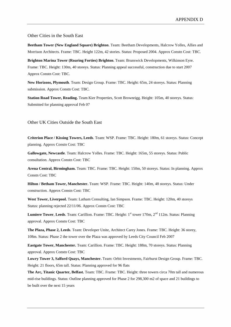
Other Cities in the South East
Beetham Tower (New England Square) Brighton. Team: Beetham Developments, Halcrow Yolles, Allies and
Morrison Architects. Frame: TBC. Height 122m, 42 stories. Status: Proposed 2004. Approx Constn Cost: TBC.
Brighton Marina Tower (Roaring Forties) Brighton. Team: Brunswick Developments, Wilkinson Eyre.
Frame: TBC. Height: 130m, 40 storeys. Status: Planning appeal successful, construction due to start 2007
Approx Constn Cost: TBC.
New Horizons, Plymouth. Team: Design Group. Frame: TBC. Height: 65m, 24 storeys. Status: Planning
submission. Approx Constn Cost: TBC.
Station Road Tower, Reading. Team Kier Properties, Scott Brownrigg. Height: 105m, 40 storeys. Status:
Submitted for planning approval Feb 07
Other UK Cities Outside the South East
Criterion Place / Kissing Towers, Leeds. Team: WSP. Frame: TBC. Height: 180m, 61 storeys. Status: Concept
planning. Approx Constn Cost: TBC
Gallowgate, Newcastle. Team: Halcrow Yolles. Frame: TBC. Height: 165m, 55 storeys. Status: Public
consultation. Approx Constn Cost: TBC
Arena Central, Birmingham. Team: TBC. Frame: TBC. Height: 150m, 50 storeys. Status: In planning. Approx
Constn Cost: TBC
Hilton / Betham Tower, Manchester. Team: WSP. Frame: TBC. Height: 140m, 48 storeys. Status: Under
construction. Approx Constn Cost: TBC
West Tower, Liverpool. Team: Latham Consulting, Ian Simpson. Frame: TBC. Height: 120m, 40 storeys
Status: planning rejected 22/11/06. Approx Constn Cost: TBC
Lumiere Tower, Leeds. Team: Carillion. Frame: TBC. Height: 1st tower 170m, 2
nd 112m. Status: Planning
approval. Approx Constn Cost: TBC
The Plaza, Phase 2, Leeds. Team: Developer Unite, Architect Carey Jones. Frame: TBC. Height: 36 storey,
108m. Status: Phase 2 the tower over the Plaza was approved by Leeds City Council Feb 2007
Eastgate Tower, Manchester. Team: Carillion. Frame: TBC. Height: 188m, 70 storeys. Status: Planning
approval. Approx Constn Cost: TBC
Lowry Tower 3, Salford Quays, Manchester. Team: Orbit Investments, Fairhurst Design Group. Frame: TBC.
Height: 21 floors, 65m tall. Status: Planning approved for 96 flats
The Arc, Titanic Quarter, Belfast. Team: TBC. Frame: TBC. Height: three towers circa 70m tall and numerous
mid-rise buildings. Status: Outline planning approved for Phase 2 for 298,300 m2 of space and 21 buildings to
be built over the next 15 years
APPENDIX D

V Building, Arena Central, Birmingham. Team: Architect Eric Kuhne & Associates. Frame: TBC. Height:
150m, 50 storey. Status: Unveiled at MIPIM, March 07, containing 600 apartments. Approx Constn Cost: circa
£150m
1 Furnival Square, Sheffield. Team: Architects Urban Innovations. Frame: TBC. Height: 17 storeys, 68m.
Status: Planning permission for Office and hotel submitted Nov 06.
Chesham House, Sheffield. Team: Developers RREEF (UK) Ltd. Architects John McAslan and Partners.
Frame: TBC. Height: 24 floors, 70m. Status: Outline planning submitted 2007 for 10,000 square metres of retail
space, 5,000 sq m offices, 19,000 sq m of residential featuring 210 apartments
Aurora Tower, Belfast. Team: Developer McAlister Holdings, HKR Architects. Frame: TBC. Height: 109
metres, 37 floors. Approx Constn Cost: £91 million. Status: Outline planning submitted 2007 for 291 luxury
apartments and 700 square metres of office space
Canopus Twin Towers, Salford. Team: Developer BSC, Arca Architects. Frame: TBC. Height: 46 and 31
floors respectively, tallest is 164 m, lower is 108m.Status: Planning application lodged Feb 2006 with Salford
City Council. 50,000 square metres of commercial space.
Estimate of Current UK Tall Building Market Value
To determine the value of the current tall building market, construction net trade cost (NTC) has been
extrapolated from the limited accurate cost information available. No definitive or reliable construction cost
information can be found for the majority of projects at design stage, or those in a later stage with competitor
construction companies. Therefore, Bovis Lend Lease project costs have been utilised from the 122 Leadenhall,
201 Bishopsgate, 125 Old Broad St, 20 Fenchurch St. and Newington Butts cost plans. This has been
supplemented by a published construction cost projection for The Shard. These six selected tall building projects
are a representative cross section of the current UK tall building market, from small footprint residential, to
existing tall building reclad/refurb, to cutting edge speculative commercial, to London’s leading mixed use
scheme. They are deemed therefore give a representative UK tall building ‘average’ construction cost.
Using the average of these construction NTC per m height above ground (as storey heights vary depending on
commercial or residential use), a calculation of the total value of the UK tall building construction market can be
made:
(NTC=Net Trade Cost)
122 Leadenhall NTC £253m / 222m height = £1.14m/m
201 Bishopsgate NTC £181m / 161m height = £1.12m/m
125 Old Broad St NTC £80m / 100m height = £0.80m/m
20 Fenchurch St NTC £257m / 160m height = £1.60m/m
Newington Butts NTC £55m / 140m height = £0.39m/m
The Shard NTC £350m/ 310m height = £1.13m/m
Average construction (NTC) cost per m height = £1.03m/m height
APPENDIX D

Therefore,
Total cost of construction for London and the South East projects listed above
= cumulative height of tall buildings x average NTC / m height
= (6968m London +422m South East) x £1,030,000/m
= £7,611,700,000
A conservative estimate of the potential BLL market share can now be made assuming 10% success rate on
pursuing 50% of the London & SE projects listed above, i.e. the win rate of work is taken 5% of total London &
SE market, which equates to winning just over 2 of the total 47 projects proposed in this region.
= £380,585,000
To determine the potential construction value per year, we need to determine the average gestation period of a
UK tall building (which has been calculated in this research as 8 years in total made up of 5 years design
development and preconstruction, plus 3 years construction).
It is unknown when any building will progress from planning into construction phase and generate potential
income if won by BLL, so assume an equal spread over the average gestation period of 8 years.
Therefore, annual potential turnover for BLL wining 5% of tall building in London & SE is:
= £380,585,000 / 8
= £47,573,000 per annum
Using the same method of calculation, the total value of tall buildings in the balance of the UK
= 2277m x £1,030,000/m = £2,345,300000
Therefore, annual potential turnover for BLL wining 5% of tall building in the balance of the UK is:
= £117,266,000 / 8
= £ 14,658,000 per annum
In summary, the total annual potential turnover for the BLL wining a conservative 5% of all tall building
projects across the UK is:
= £62,231,000 per annum
Mixed Use Comes of Age
APPENDIX D

The third emerging tall building market referred to earlier in this report is that of the mixed use tall building.
Design for mixed use tall buildings as opposed to single occupancy presents complex problems and
opportunities. This form is increasing in popularity worldwide, as well as in the UK. There are a number of
issues specific to this form of tall building that need careful consideration to ensure success:
Optimisation of floor plate design to suit different requirements for floor space depth and riser
configurations, using either a stepped floor plate or tapered building profile;
Use of efficient transfer structures to accommodate changes in the structural grid;
Stacking of the tower efficiently to optimise use of differing floor plate sizes and minimise lifting
requirements by locating lighter lift demand occupiers toward the top (residential and hotel users)
thereby reducing car numbers and core size;
Maximising the efficiency of means of escape by phase evacuation, fire escape lifts, efficient core and
stair layouts and accommodating increased security and privacy issues of multiple occupiers;
Provision of dedicated services to each occupancy group and isolating each group for fire, security and
acoustics;
Allowing heating and cooling load transfers between occupier groups to maximise energy efficiencies.
A successful example of a mixed use tall building is New York’s recently completed $1.7 billion, 2.1million sq
ft Time Warner Center, which is acknowledged to currently lead the way for occupier diversity. Behind its
glazed façade there is a four-level shopping centre over a basement supermarket and health club. Two offices sit
on top the mall, one devoted to Time Warner, including studios for CNN and one tenanted. A residential tower
rises above the restaurant, bar and retail area to the South. The North tower includes a 251-room hotel and more
private apartments.
The biggest and earliest advantage for the developer Related Companies, was that the various uses balanced the
financial risks and delivered an early income stream in the form of off-the-plan sales of residential.
Time Warner Center used a different structural and mechanical solution for each occupier group. The most
efficient system was to transfer the high loads from the concrete frame and shear wall structure for the hotel and
residential levels through gigantic trusses to a steel-framed office grid below. The long spans in the shopping
concourse below this fell outside the higher bulk of the building requiring further transfer structures.
Additionally each occupier group had to have its own lobby presence requiring seven lobbies at street level. Sky
lobbies would have been more space efficient, but tenants and owners who pay these rates do not want to
transfer. One hundred-thirty elevators serve the building.
The UK leading example of a mixed use tall building is still at design stage, in the form of Renzo Piano’s
London Bridge Tower. This stacks narrow spire of private apartments above a hotel over a thickening base for
offices and retail, all over the refurbished railway station. The functions meet at dramatic sky lobbies, visible
from outside. The specific construction related issues in building mixed use tall buildings will be examined
further in this research.
APPENDIX D

Costing of Tall Buildings
The cost and scarcity of developable land, the permitted footprint, building bulk and height, quality of
specification and the time required for design, construction and occupation are all key cost drivers of tall
buildings. The medieval street pattern of the City of London creates small, complex footprints. The proximity of
listed buildings and conservation areas influences the articulation of tall buildings. Both factors serve to produce
structures of relatively high cost (Watts, 2005).
Tall buildings have a longer lifespan than low rise equivalents, due to the high level of first cost and high level of
removal costs, favouring their retention. Modern tall buildings are planned for a much longer lifespan, with
higher initial investment in their design and capital cost being offset over the long life cycle of the building.
The main opportunities of tall building design and construction are the exploitation of standardisation,
modularisation and repetition across major cost elements along with the overlapping of the construction
activities. Achieving and maintaining speed is crucial to successful project delivery. Procurement strategies that
allow the overlapping of design, procurement and construction are essential to success.
EC Harris developed a model in 2004 which plots construction cost against height for residential towers. They
examined 7 projects and plotted construction cost against height. This shows cost increases with height, but
levels off at 50 storeys. The major rise in costs is between the 20th
and 40th
floor due to the increased complexity
of building at height, which then achieve economies of scale above 40 floors. This also shows the cost premium
for complex shape and design. To achieve planning consent and good sales, a residential tower design needs to
be attractive, but not necessarily cutting-edge. They indicate a large percentage of construction costs for
mechanical (comfort cooling and extract) and electrical systems (structured wiring, network, audio and security
technology). Additionally, high costs are allocated to provision of main and ensuite bathrooms, kitchens (EC
Harris & Knight Frank LLP, 2004).
Tall buildings are intrinsically less efficient and more expensive than low riser schemes due to lower Net to
Gross ratios because of the space required for risers and cores. Additionally, the efficiency of cladding the tower
is low due to the low wall to floor ratio (small plan area). Structural design is a key driver of construction cost.
(Morrell, 2006). Every aspect of the tall building should be optimised for material content, cost and time.
The key engineering and cost issues include:
Slenderness Ratio – Slenderness ratio is the relationship between height and plan width. Conventional
ratios are 1:8 optimum and 1:12 maximum. Wind has a bigger effect on slender tall buildings and can set
up forces which needs additional structural mass or dampers to counteract.
Building Orientation – Wind load will vary depending on orientation to the prevailing wind. Correct
building profile orientation can reduce wind load and therefore cost.
Swaying and Damping – wind induced motion can be felt by occupants. Wind tunnel testing should
guide the design to reduce effect. Costly structural damping can be introduced. Concrete’s mass assists
APPENDIX D

in resisting the sway more efficiently than steel. Additional active damping may be required at great
cost.
Stability and Robustness – Tall buildings generally resist lateral loads through their core. The more
slender the tower, the greater need to utilise the full depth of the building by having additional structure
at the perimeter – outriggers, mega-bracing and bundled tubes increase the bending stiffness of the
building. Robustness, or collapse resistance has been an area of great focus since 9/11 to ensure a direct
and efficient load path to the foundations.
Structural Grid and Floor Structure – structural grid requirements affects the frame and foundation
systems available. Floor structural depth will effect space available for service zones and flexibility of
space for different users and provide the minimum economical storey height. The saving of 100mm per
floor on a 40 storey building could give an extra floor and therefore, revenue. The balance between
structural repetition and variety can have large time and cost consequences.
Thermal Mass - heating and cooling are relatively constant for a residential tower so concrete slabs will
act as a thermal store. Cheaper night time power can be used for heating and cooling. Concrete also
provides acoustic damping.
Façade Treatment – Cladding on a tall building must be of high specification and detailing to
accommodate the relatively large movements each elevation experiences due to differential loadings
from solar gain, wind and rain. Developers invariably demand large areas of glass to maximise views
and hence income. Higher glass performance is necessary as glass area increases to allow Part L
requirements to be met. Interstitial blinds or external shading are commonly required on the Southern
elevation (UK) to offset solar gain. Active vented facades are more expensive but can be offset by lower
running cost. The more slender the building, the lower the wall to floor ratio, the higher the proportional
cost of cladding. External envelope costs are a quarter of the total project cost of a high rise scheme
(Watts, 2006).
Steel V’s Concrete Frame – numerous advantages and disadvantages of both. The decision will be driven
by the most efficient frame solution for the site, specialist contractor availability and cost.
Internal Fit Out – The high level of finishes specification for a tall building lead to high cost of fit out. In
tall residential schemes of high density and specification, the cost of £9000 - £12000 per bathroom and
£15000 - £40000 per kitchen. Bathroom pods may cost more, but offer higher quality control and
reduced fit out time if the layouts are repetitive. Accommodation of large tolerances and movement
associated with tall buildings in finishes is expensive, It may be cheaper to tighten tolerances by
stiffening the structure.
M&E Installations – building over 100m in height increases M&E costs disproportionately. This can be
mitigated by careful services engineering:
Heating and cooling systems above 100m need to cope with higher pressures adding 30% to cost; fully
ventilated schemes are expensive due to the size of ducting required, reducing net floor area.
Intermediate plant floors may be beneficial above 100m, but take floor area and mechanical ducting will
penetrate the facade; Dry risers can protect schemes up to 60m in height, above this sprinklers are reqd at
a cost of £25/m2; Lift installation cost increases with height and demand volume. It is cheaper and less
APPENDIX D

demand on floor space to increase speed of lifts rather than number, however, high speed lifts have a
high cost premium and long lead times. Fire-fighting provision must be made over 18m in height. Lifts
typically add 3% to construction costs (EC Harris 2004).
Logistics – tall buildings are generally constructed on constricted inner-city sites, especially true in
London. This may result in inefficiencies through delivery, storage, handling, and delivery to the work
face via hook or hoist. Trade contractors have been shown historically to add a premium to cover their
expected risk of inefficiencies. This is difficult to price and can be substantial percentage of cost.
Productivity is affected by the risk of winding off delaying deliveries and installation as well as the
extended travel time for workforce to workface. This may be partially offset by the ability to work on
many levels simultaneously, but depends on the ability of the main contractor to plan, coordinate and
avoid the typical labour peaks and troughs. Welfare facilities at regular intervals up the building reduce
lost time of labour in hoists. Frame cycle times are fundamental to programme as is achieving a
watertight building, both on the critical path allowing dry finishing trades to commence. Correctly sized
and located craneage is mandatory to provide sufficient hook time for dependant trades. Long
procurement times for specialist tall building elements lead to high inflationary costs, especially relevant
as the artificial Olympic deadline looms. As a result, preliminary costs will be higher for a tall building.
This is supplemented by the increased health and safety requirements and higher risk of programme
failure due to the high level of repetition and coordination.
Phasing – With a residential tower there is a balance between early release to the market giving an early
revenue return, not flooding the market and minimising construction costs. There is limited opportunity
for phased release in a tall building as opposed to a horizontal residential development, but is vital for
scheme viability. Early contractor involvement will allow investigation of horizontal and vertical
phasing of a tower achieved through early scaffold free elevations, early commissioning, and segregation
of lifts and staged commissioning of services. Phasing will increase construction cost as it will not be the
most efficient work method, needing higher levels of management coordination, longer trade durations
and enforced return visits.
Main Contractor Preliminaries - The inherent cost and complexity of tall buildings will inevitably result
in higher levels of staff, accommodation, plant and equipment for a longer duration. Investment in the
main contractors’ preliminaries will mitigate pressures on trade contractors’ preliminaries, which can be
substantially greater for tall buildings and will avoid potential duplication (Watts, 2005). Additionally,
design and construction contingency sums are much greater for tall buildings when indexed against
lower buildings.
Height equals Price – the residential market established a premium for higher level properties, to the
extent that not only penthouses but sub-penthouses command a specialist market. Basement properties
are discounted as they offer no outlook, ground floor are at a higher risk of being broken into, upper
floors command good light and views. This gives a clearly established relationship between floor height
and price. This is blurred on tall buildings as the floor difference becomes less distinct. The lowest floors
have a negative price impact with rapid price growth occurring above these floors. This increase then
APPENDIX D

levels out over the mid-section of the tall building, with a huge growth for the top third floors. This
pattern is dependent on the condition and strength of the market (EC Harris, 2004).
Specialist Market, Small Pool – There are a limited number of main contractors interested in tall
buildings in the UK, limited further by relevant experience and availability. The limited pool of high rise
main contractor and trades reduces competition and therefore raises price. Early contractor involvement
through partnering can give greater periods to review the design to ensure buildability. Additionally,
once established, partnering will allow repetitive design and standardisation across the supply chain.
Economies may be made from modularisation and prefabrication. It is acknowledged that trade
contractors price a higher level of risk in tall buildings due to lack of experience and their bespoke
nature. Better contractor knowledge through early involvement should lead to a lowering of these risk
premiums.
Tall Building Revenue Generators
To offset the high cost of building tall there are greater revenues generated. Irrespective of floor plates, landmark
status, form and proportion, development costs per m2 of gross floor area increase with height. To be viable the
value of tall buildings per m2 must also be higher and market evidence suggests it is possible for tall buildings to
provide an acceptable long-term return. The macro and micro economics for a tall building will vary according
to location. London is a ‘young market for tall buildings’ and as increased knowledge and experience is gained,
cost and efficiency premiums may reduce (Watts 2005).
Knight Frank believes the revenue premium for tall buildings is due to:
The scale of the development adding amenity value in the form of exclusive shops, restaurants, bars and
hotels;
The brand awareness – Beetham brand has been established though their internal marketing of both
towers;
The height of the profile - landmark developments infer high quality build, fittings and fixtures.
The rarity value attached to these developments. This factor may reduce as the supply of tall buildings
increase.
A case study was conducted of 3 residential tall buildings; the £150m development Beetham Tower, Deansgate,
Manchester which showed it achieved an 18-23% price premium over the standard new build market. Beetham
Tower, Old Hall St in Liverpool showed an increase of 15%. Crosby Homes 1 Deansgate, Manchester was seen
to have led the market on high density tall residential and achieved an 8-10% premium, but was only 14 stories.
(Knight Frank Residential Research 2004).
APPENDIX D

However, the financials of building very tall are brought into focus by an American study (EC Harris 2002)
which plots the construction cost and whole life cycle cost per occupant of a number of tall buildings of varying
heights. The results indicate the best return on investment is given by 20 storey buildings.
APPENDIX
Data for Graphs within the ‘UK Tall Building Market Sector Report - An Overview of the
Market and its Forecast to 2012’. (May 2007)
Key Market Players, Contractors, Offices, London. ‘All Buildings since 1999’ March 2007 (Cityoffices)
Main Contractors Projects Total m2 Total ft
2
1 Bovis Lend Lease 43 969,399 10,434,528
2 Canary Wharf Contractors 11 570,776 6,143,784
3 Sir Robert McAlpine 33 507,322 5,460,771
4 Skanska 23 481,477 5,182,578
5 Mace 10 237,590 2,557,399
6 HBG Construction 19 232,652 2,504,246
7 ISG InteriorExterior 18 181,324 1,951,756
8 Laing O'Rourke Group 11 154,190 1,659,688
9 Not Appointed - Main Contractor 5 147,353 1,586,095
10 Carillion (London) 10 119,391 1,285,115
11 Carillion 11 110,367 1,187,981
12 Kier London 16 93,388 1,005,220
APPENDIX D

Key Market Players, Contractors, Offices, London. ‘All Buildings Under Construction or Completed Since
2005’ March 2007 (Cityoffices)
Main Contractors Projects Total m2 Total ft
2
1 Bovis Lend Lease 17 446,825 4,809,586
2 Mace 6 193,045 2,077,920
3 Sir Robert McAlpine 11 122,658 1,320,280
4 Skanska 5 122,620 1,319,871
5 HBG Construction 6 100,001 1,076,402
6 ISG InteriorExterior 7 75,990 817,950
7 Canary Wharf Contractors 1 32,516 349,999
8 Laing O'Rourke Group 3 25,405 273,457
9 Carillion (London) 3 21,681 233,372
10 Laing O'Rourke Group 1 18,680 201,070
11 Kier London 4 18,563 199,811
12 Overbury 2 17,838 192,007
Key Market Players, Contractors, Offices, London. ‘All Buildings Potentially in Pipeline’ March 2007
(Cityoffices)
Main Contractors Projects Total m2 Total ft
2
1 Not Appointed - Main Contractor 5 147,353 1,586,095
2 Bovis Lend Lease 4 106,201 1,143,139
3 Skanska 2 55,650 599,012
4 Laing O'Rourke Group 1 36,975 397,996
5 Sir Robert McAlpine 2 24,193 260,411
6 ISG InteriorExterior 2 21,864 235,342
7 Canary Wharf Contractors 1 18,580 199,994
8 Mace 1 7,804 84,002
9 Wates Building Group 1 6,500 69,965
10 Galliford Try 1 4,548 48,954
11 SJS Management 1 2,972 31,990
12 Kier London 1 1,900 20,451
APPENDIX D

Construction News Contracts League, Commercial Contractors (ex-Retail) Jan 2006 – Jan 2007 (15.02.07)
Main Contractors Projects No Man £m
Trad £m
1 Bovis Lend Lease 13 150 443
2 Skanska 7 0 472
3 Laing O'Rourke Group 16 0 459
4 Mace 7 16.5 415
5 Sir Robert McAlpine 12 0 418
6 HBG Construction 22 0 378
7 Kier London 52 0 371
8 ISG InteriorExterior 39 0 333
9 Morgan Sindall 82 0 289
10 Miller 15 0 228
APPENDIX D
APPENDIX D

___________________________________________________________________________
APPENDIX E
APPENDIX E BUSINESS CASE FOR THE LIFTING WING

University of Surrey
School of Management
MSc Entrepreneurship and Creativity
Assignment Two
Name of CICE EngD Student: Ian Skelton I.D No: 6046980
Title of MSc Project: Business Plan for the Think Tall Company
Name of Module Contributor: Dr Spinder Dhaliwal
Submitted: 14th November 2007 via email
Word count: 3004 (main text body)

2
Executive Summary
The Think Tall Company is concerned with developing innovative construction techniques allowing
more efficient building of tall buildings. It has at concept stage a number of innovative tools that will
reduce the build period tall buildings by eliminating or reducing construction time, cost and safety risks.
The company is run by Ian Skelton, a qualified Civil Engineer, Master of Project Management and shortly
to be, Doctor of Engineering. Ian has worked as a main contractor on tall buildings both in the UK and
Australia and so has a detailed understanding of the polarised needs of time, cost, quality and safety on
such projects. The Think Tall Company Tools are designed to satisfy these diametrically opposed needs.
The first such tool to be ready for the market is the Lifting-Wing. It is a 6.5m long x 3.5m wide by 2.5m
high aerodynamic wing-on-end, built of a light weight, high impact resistant clear plastic skin over a frame.
The Wing is connected to the crane hook and is lowered over the bulky construction material to be lifted
and propped off the load, fixing its position. The Wing fully encapsulates the load suspended from the hook
of a tower crane, thereby giving the load a predictable and more controllable wind profile, allowing safe
lifting in higher and gustier wind-speeds. This will reduce the industry accepted norm of 40% down time
for the tower crane, saving time on the critical path of the tall building construction programme and hence,
substantial costs.
The intellectual property of this and the next concept tool to be market ready, the Mag-Spanner, are
currently protected by International Online Copyright Registration and are about to be internationally
patented.
The UK tall building market sector is forecast over the next 3-5 years to be circa £10billion Net Trade Cost.
Growth is forecast conservatively as 5% annually, boosted by the recent glut of tall building planning
permissions approved in London and other cities and topped by the proposed Olympic residential towers.
The market opportunity that this company addresses is the current boom in demand for UK tall buildings,
directly comparable in size to the skyscraper boom of Manhattan Island in the 1920’s. Every tall building
construction company must be seen to build the highest quality, in the fastest and safest manner to win
these prestige projects. The innovative tools produced by the Think Tall Company will be in demand from
every one of these specialist construction companies.
The central competitive advantage of this company and its innovative products is that no-one else is in this
specialist arena. Even on an international scale, no-one is producing specialist products of this type as they
fall between traditional client demands in the construction industry: Tower crane suppliers and major plant
companies have no interest in increasing construction speed (therefore reducing equipment hire time and
revenues), whilst trade contractors similarly have little interest in committing to tighter programmes than
the ‘norm’, with the tower crane being their Get-Out-Of-Jail Card, as its time and cost risk are traditionally
the main contractors. Main contractors themselves are not interested in producing niche products to reduce

3
time and cost risk as it is deemed outside their core business. This is where the Think Tall Company comes
in.
Traditionally, if tower cranes are winded off, this may cause an extension to the tall building programme,
resulting in either the tall building client paying increased preliminary costs (Construction Management
contract), or the Main Contractor loosing profit (Lump Sum Contract). The niche products of The Think
Tall Company capitalise on this unexplored market opportunity and once proven and utilised by one of the
industry players (traditionally slow to accept innovation and change), they will be demanded by every
building company to retain their competitive edge. They will become vitally important to two very wealthy
customers – the tall building client and main contractor.
The objectives of the company in the short term are:
1. Commission a scale model of the Lifting Wing and full scale Mag-Spanner
2. Wind test the Lifting Wing scale model. Determine increased levels of wind speed safetly
serviceable against current ‘norm’ windspeed
3. Calculate typical tall building programme saving and hence value of prelim cost saving, ignoring
the value of performance clauses or Liquidated and Ascertained Damages clauses.
4. Secure International Patent
5. Furnish wind test report and obtain Lifting Wing reviews from key market players (BLL Safety
Department, BRE, Tim Watson Consultants, CPA’s Tower Crane Interest Group, HSE)
6. Determine best product for construction, tender production cost to 4 prospective companies.
Contract one manufacturer. Test full scale Wing on BLL site. Gather expert reviews.
7. Determine sale verse rental marketing strategy and establish agreements with plant hire
companies, though crane suppliers or direct sales force.
Medium term objectives are to successfully establish the manufacture and sale the Lifting Wing, commence
production of the Mag-Spanner and develop the next product. The key marketing strategy will be to
develop sales leads through existing construction industry contacts.
Long Term objectives are the establishment of The Think Tall Company in the industry due to the existing
products, the development of the future stream of products and investigation into the feasibility of a tall
building consultancy service. A natural market growth to be targeted early is overseas, with the US, Asia
Pac and UAE all undergoing tall building booms currently.
Evidence of success of the Company Director can be determined from the CV in Appendix 1. Evidence of
success of the company will follow shortly as initial concept models are tested, reviewed by trade experts
and working prototypes are tested on Bovis Lend Lease pilot projects.
It should be noted there is an ongoing early discussion with Bovis Lend Lease Ventures regarding the
raising of capital to fund the development of the Lifting Wing.
The current finance requirements, stake in the company on offer and the proposed exit strategy for the
investor are excluded from this assignment, but will be worked up separately.

4
Contents
Introduction to the Think Tall Company and its People
Products – the Think Tall Tools
The Market
Business Strategy
Marketing Plan
Sales and Distribution
Production Strategy
Provisional Costs / Revenue
Conclusion - Evaluation of the Exercise
References
Appendix

5
Introduction – the Think Tall Company and its People
The Think Tall Company is a new venture concerned with developing innovative construction
techniques allowing more efficient building of tall buildings. It has at concept stage a number of innovative
tools that will reduce the build period tall buildings by eliminating or reducing time and cost construction
risks. The company is run by Ian Skelton, a qualified Civil Engineer, Master of Project Management and
shortly to be, Doctor of Engineering. The ideas have resulted from the research into innovative tall building
techniques Ian has undertaken for the Engineering Doctorate at Loughborough University and from his
experience working for main contractors on tall buildings both in the UK and Australia. This detailed
understanding of the polarised needs of time, cost, quality and safety on such projects has given rise to the
Think Tall Company Tools, designed to satisfy these diametrically opposed needs.
Two tools are close to being ready for the market. These are the Lifting-Wing and the Mag-Spanner.
Both products break new ground and offer something not currently available in the market place. They are
described in detail in the next section.
Research shows the average UK tall building is circa £200million pounds (Net Trade Cost) and there are
thirty nine tall buildings potentially starting on site in the UK in the next three years .This specialist market
sector is forecast over the next 3-5 years to be circa £10billion (NTC). Growth is forecast conservatively as
5% annually, until 2012, when construction forecasts are uncertain due to the completion of the Olympics
and potential downturn.
However history shows us that the construction industries in key foreign markets will boom whilst the UK
is in potentially slowing down, ideal for the Think Tall Company’s medium term international expansion
plans.
The market opportunity that this company addresses is the current boom in demand for UK tall buildings,
directly comparable in size to the skyscraper boom of Manhattan Island in the 1920’s. Every tall building
construction company worldwide must be seen to build the highest quality, in the fastest and safest manner
to win these prestige projects. The innovative tools produced by the Think Tall Company will be in demand
from every one of these specialist construction companies.
The central competitive advantage of this company and its innovative products is that no-one else is in this
specialist arena. Even on an international scale, no-one is producing specialist products of this type as they
fall between traditional client demands in the construction industry: Tower crane suppliers and major plant
companies have no interest in increasing construction speed (therefore reducing equipment hire time and
revenues), whilst trade contractors similarly have little interest in committing to tighter programmes than
the ‘norm’, with the tower crane being their Get-Out-Of-Jail Card, as its time and cost risk are traditionally
the main contractors. Main contractors themselves are not interested in producing niche products to reduce
time and cost risk as it is deemed outside their core business.

6
This is where the Think Tall Company comes in. Traditionally, if tower cranes are winded off and cause an
extension to the tall building programme, either the tall building client will pay increased preliminary costs
(Construction Management contract), or the Main Contractor will lose profit (Lump Sum Contract). The
niche products of The Think Tall Company capitalises on this unexplored market opportunity and once
proven to and utilised by one of the industry players (traditionally slow to accept innovation and change),
will be demanded by every building company to retain their competitive edge. They will become vitally
important to two very wealthy customers – the tall building client and main contractor.
The current organisational structure is sole trader. There are currently no plans for increasing the people
employed by the company as short term needs are better satisfied by outsourcing to independent specialists,
for example the model making, wind testing, design adjustments, full scale mock-up production, seeking
expert opinions, full scale tower crane trials etc.
Once this development stage has been successfully completed, specialist staff will be recruited to assist
with production, sales and marketing.
Business advisors todate include Bovis Lend Lease Ventures, Barclays Bank, and Waseem Malleck (MD of
C&G Construction).
The existing alliance with Bovis Lend Lease Ventures is a potential source of future investment and
business mentoring. Additionally, BLL has an established construction industry supply chain including
several large plant hire companies that could be approached for a potential sale and marketing alliance.
Long Term objectives are the establishment of The Think Tall Company in the UK industry via the proven
capability of these two products, the development of the future stream of products and investigation into the
feasibility of a tall building consultancy service. A natural market growth to be targeted early is the US,
Asia Pac and UAE construction markets, all undergoing tall building booms currently, with no-one
currently offering this specialist service or advice.
Arup Wind Engineering, a subsidiary of the worlds largest consultant structural engineering company, have
been approached for wind testing and commented that this concept is ground breaking in an area not
previously envisaged.
Products – the Think Tall Tools
The first two tools to be ready for market first are the Lifting Wing and the Mag-Spanner:
The Lifting Wing allows the potential of lifting construction loads in higher than currently acceptable
wind speeds as it gives the load more predictable and more controllable wind profile. The result is safer
lifting in higher and gustier wind-speeds. This will reduce the industry accepted norm of 40% down time
for the tower crane, saving time on the critical path of the tall building construction programme and hence

7
substantial costs. ‘Winding off’ is the term used to describe when the wind speed is such it makes the load
on a tower crane unstable and act unpredictably, or if the driver feels uncomfortable with the risk of
continuing. It is interesting to note that this may occur at wind speeds of less than half that designed as
operationally acceptable by the crane manufacturer. Weather forecasts show the UK climate is getting more
adverse with higher wind speeds expected to more regularly occur over more months.
It can be demonstrated that main contractor preliminary costs on a typical UK tall building are in the order
of £200,000 per month (including site staff, offices, crane hire etc) and the typical tall building construction
programme is 36 months (three years), with the tower crane being critical for 26 months (two years). The
existing industry accepted down time of 40%, equating to 10 months (due to several possible factors, but
the most common of these is winding off). Conservatively estimating the Lifting Wing only saves 20% of
this crane down time equates to a cost saving of 2 months at £200,000 per month = £400,000 over the
construction period of a typical UK tall building.
The Lifting Wing is therefore potentially a high cost / high revenue tool either rented or sold to
construction companies. There could feasibly be up to four per site, depending on the size of the loads to be
lifted and number of tower cranes required to lift in higher winds. Cost of production would be
comparatively cheap, estimated to be in the order of £2000 per unit, with an expected life span of 5 years
due to wear and tear on site. Maintenance would be minimal, but checking and re-certification would be
undertaken annually.
The Lifting Wing could be sold in the region of £15,000 - £20,000 without being excessively priced for the
typical tall building main contractor or crane hire company consumables budget. Especially when
demonstrated that the Wing can save circa £6500 per salvaged lifting day, therefore only needs to save 3
days to pay for itself! Alternatively it could be rented at a monthly rate to be calculated.
The Mag-Spanner is a magnetised hand tool to be used by structural steel frame erectors in the bolting up
of steel beams and columns. A pair of Mag-Spanners are connected by lanyard to the steel fixer’s tool belt.
One is used to securely hold the bolt and washers, another holds the nut and washers allowing safe bolting
up without the risk of dropping these items from height. Items such as these are potentially lethal when
falling from in excess of 10m and is currently a major health and safety risk on all steel framed building
over two storeys, not isolated to tall buildings alone.
The Mag-Spanner is a low cost, medium return tool, sold to steel erection companies to issue to their men.
There could be up to twenty per site as they are used in pairs and bigger projects commonly have two teams
of five steel erecting crews. Cost of production would be very cheap, estimated to be in the order of £5 per
unit, with a life span of circa 10 years. Maintenance would be the offer of free re-magnetising should it be
necessary. The Mag Spanner could be sold for £100 per pair, equating to the cost of a good quality pair of
wrenches. Lanyards could be sold separately as they may wear out.

8
Both tools are unique, with nothing similar being offered in the UK market, or internationally.
The intellectual property of these tools is currently protected by International Online Copyright
Registration and are about to be internationally patented on receipt of funding.
The Market
The tall building market is highly segmented. It is a very specialist, high value market with many contracts
negotiated rather than tendered, as lowest cost is not the way to procure the level of quality service and
product demanded. As already highlighted in the Executive Summary, research undertaken in 2007 shows
the average UK tall building is circa £200million pounds (Net Trade Cost) and. This specialist market
sector is forecast over the next 3-5 years to be worth circa £10billion (NTC). Growth is forecast
conservatively as 5% annually, until 2012, when construction forecasts are uncertain due to the completion
of the Olympics and potential downturn.
However economic history shows us that key foreign market construction industries will boom whilst the
UK is potentially slowing down, offering the ideal opportunity for then established UK Think Tall
Company to expand operations overseas.
The market opportunity that this company addresses is the current boom in demand for UK tall buildings,
directly comparable in size to the skyscraper boom of Manhattan Island in the 1920’s. Every tall building
construction company worldwide must be seen to build the highest quality, in the fastest and safest manner
to win these prestige projects. The innovative tools produced by the Think Tall Company will be in demand
from every one of these specialist construction companies.
Business Strategy
The Think Tall Company will be in a competitive marketplace. It is entering a niche market with new
products offering the key point of difference. A market analysis has been undertaken using Porters Five
Forces and a SWOT matrix.

9
Forces driving
industry competition – ME Porter, 1980
POTENTIAL ENTRANTS
Threat of new entrants
SUPPLIERS
Bargaining power of suppliers
INDUSTRY COMPETITORS
Rivalry amongst
existing firms
Bargaining power of buyers
BUYERS
Threat of substitute products
SUSBSTITUTES
Power of Suppliers: The power of suppliers will be weak as there are large numbers of potential
suppliers and intense competition amongst them, including overseas companies.
Threat of new entrants: The barriers to entry into this sector are high as it is highly specialized
knowledge. Risks of copying these products would be overcome through international patented
technologies. If not adequately protected, a rash of copy products could swamp the marketplace and
endanger the established high quality reputation.
Power of buyers: The power of buyers in this industry is high. A relatively small number of customers
control the market. However, the innovative technology offered by the Think Tall Company would serve
to mitigate this power.
Threat of substitute products: At present there is no known or likely prospect of products that can
substitute for the Think Tall Tools in this market sector. The threat of substitutes is low provided patents
are in force.
Rivalry amongst existing firms: There are no direct competitors. The closet is the Plant and Tool hire
market, rivalry amongst them is strong, leading to heavy price competition. However the strategy would be
either to sell direct to the main contractors via the client, tower crane suppliers or form an alliance with the
two Preferred Suppliers of Bovis Lend Lease’s Supply Chain.

10
SWOT Analysis (Internal & External)
The Internal Strengths and Weaknesses of the Think Tall Company, and the External Opportunities and
Threats it faces, can be summarised as follows:
STRENGTHS OPPORTUNITIES
Alliance with Bovis Lend Lease
Innovative technology
Professional management
Low cost base, high revenue
Ability to expand production swiftly
Ability to shift production overseas,
reducing costs
Low production lead times
Low capital consumption, high revenues
Detailed knowledge of specialist market and
key players
Growing, very lucrative market sector
Huge potential savings to customers
No rival products
Current widespread Tall Building Client
dissatisfaction with build periods and wind
risk
New consumers entering the market as tall
residential is the trend across UK
Growing overseas tall building markets, US,
Asia Pac, UAE
WEAKNESSES THREATS
Low resources
Lack of sales experience
Dependence on suppliers
Wind tests not yet complete
Industry expert opinions not yet gained
HSE approval will be reqd.
International Copyright for intellectual
property and products not in place
Undercut by copy-cat technology from main
tool hire companies
Potential economic recession could impact
on construction spending
Downer if involved in a safety incident on
site
The Think Tall Company’s strengths will allow for exploitation of the opportunities in the market. This
innovative technology has no current rivals, leaving this company solely placed to take advantage of the
existing dissatisfaction amongst tall building clients with the period of build, safety of the build process and
desire to reduce levels of risk. Both products go toward solving these issues.
Current weaknesses and threats will be mitigated by securing patents and intellectual property rights,
conducting wind test to prove the aerodynamic theory, gaining industry opinions, conducting full sized
trials and determining a detailed sales V’s leasing strategy. The existing alliance with Bovis Lend Lease
and detailed knowledge of expert organisations, will allow the speedy acceptance of the products once
trials are completed. On the product side, the company will be less vulnerable to price competition because
of the lower costs involved in the production of the technologically innovative products.

11
Marketing Plan
The major marketing activities that the company plans to undertake include:
The core strategy for getting tall building clients on board to encourage recommended selling direct to
main contractor’s and possibly key plant hire companies and crane suppliers.
The tall building client and the main contractor will be made aware of the products through articles
planned to be published in recognised industry professional and academic journals, followed by an
advertising campaign in the same publications. Additionally, direct contact will be made to key
potential clients through existing industry contacts.
The potential secondary client, the plant-hire or tower crane suppliers will be made aware by the same
three methods.
The Thinking Tall Company will launch an educational website offering free advice to customers on
the details and test results of the two existing tools, to be supplemented as further tools are developed.
The targeted marketing approach will achieve widespread exposure in a short timescale and will allow
relationships to be quickly forged with key clients establishing the products firmly in the marketplace.
Sales and Distribution
The major marketing activities that the company plans to undertake include:
A sales force will be hired as demand increases. This could either be developed in-house or a potential
alliance could be formed with Speedy Hire, BLL’s preferred construction equipment and plant-hire
company. They would be paid an intermediary margin of circa 1% for the current range of products.
The products would be warehoused in Windsor, offering good access into London, the key UK tall
building market location. Mag Spanners would be dispatched using a courier service, the Lifting Wing
would be delivered via flatbed Lorries. Initially, a contract would be entered into with a local Sales &
Distribution outfit that offer the entire service.
Customers would be invoiced with the delivery of the product and followed up in 14 days.
Settlement terms would be payment in 14 days on receipt of delivery, or if leased, payment of delivery
and first months rent on delivery, each following month paid in advance.

12
Production Strategy
The production strategy that the company plans to undertake includes:
A contract would be entered into with a number of production plants either contracting the entire
production, or license the technology. Tenders will be sought on both forms and the most efficient
method selected.
Different production facilities would be required for the Lifting Wing which requires laying up of clear
plastic over a lightweight carbon fibre frame, and the Mag Spanner which requires lathwork and metal
tooling. Quality assurance procedures would form part of the contract for both production facilities.
The total production cost per unit has not yet been established, but will be determinable upon the
completion of the full scale mock-up and decisions on the most efficient material usage.
The product lead-times will also be determinable on completion of each mock-up.
Policies would be set up covering limited stock holding to ensure that stock does not consume too
much working capital and ensuring sufficient lead time for component reordering.
Production capacity would be established as part of production the tendering process.
Provisional Costs / Revenue
The amount of finance needed to execute this plan has not yet been determined. This will be answered in
the next stage following the completion of wind testing, mock-up testing and production tendering.
The potential methods of fund raising include approaching Lend Lease Ventures, Business Angels, Venture
Capitalists, Bank Finance, or a mixture of these.
Money raised will be utilised on executing this business plan, establishing demand for and stock of the
existing tools and commencing development on the next suite of tools and services.
Investors capital and return would be released via an agreed percentage of sales revenue and through a
trade sale, flotation, or a management buy-out envisaged within 5 years.

13
Conclusion -Evaluation of the Exercise
Following on from the bewildering array of definitions of the ‘Entrepreneur’ discovered in the first
assignment, the literature review for this assignment shows there is an equally wide variety in the academic
views on writing of business plans and their inclusions. Research even seems inconclusive as to whether
writing a good business plan lends to a successful business, rather, the main body of research seems to
focus on not having a business plan leading to the failure of a business (Baechler 1996, Labich 1994, Perry
2001). However, several academics were found that extolled the virtues of a good business plan (Hormozi
et al’s 2002, Maranville 1999, O’Hara 1994, Sahlman 1997), with Maranville’s quote ‘failing to plan is
planning to fail’ and Hormozi et al’s quote ‘If you don't know where you are going, any path will get you
there’ ringing true to the writer.
Of these positive viewpoints, Sahlman details a simplistic approach to business planning in the Harvard
Business Review (1997). His logic was followed, but embellished to suit the needs of the Think Tall
Company.
The writer found the exercise initially frustrating, but eventually extremely satisfying. Completing the
business plan process for the first time (excluding the financial side) and capturing the full potential of one
idea as an entrepreneurial opportunity was something the writer had meant to do for years, but never
actually got down to it. Initially it was difficult to concentrate solely on one or two ideas and capture the
next steps in the development process. The temptation was to ‘concept brainstorm’ and list out hundreds of
different potential product ideas.
The second difficulty was keeping the plan short and concise, not attempting to capture all relevant date in
this one document. Determining details of the most suitable marketing, sales and production strategies had
not been previously done and caused much difficulty, requiring constant direction from the literature
review.
Finally, the writing of this business plan crystallised the scale of the opportunity for this endeavour, and the
fact that no-one else is looking into this area. It also forced the realisation of two design problems and one
marketing and sales problem that need to be overcome – several influential industry bodies will need to be
won over to ensure this venture ‘has legs’. In the classic catch 22, these cannot be resolved until sufficient
international patenting is in place protecting the intellect – itself an expensive process requiring funding.

14
References
Arkebauer J. (1995) The McGraw-Hill Guide to Writing a High Impact Business Plan: A Proven
Blueprint to Entrepreneurs. New York McGraw-Hill.
Baechler M. (1996). Do Business Plans Matter? Inc. 18, 2, 21.
Bygrave W. The Portable MBA in Entrepreneurship. New York. J Wiley & Sons
Gartner, WB. (1988). Who is an Entrepreneur? is the Wrong Question. American Journal of Small
Business. Florida International University.
Hall, G (1992). Reasons For Insolvancy Amongst Small Firms - A Review and Fresh Evidence.
Small Business Economics 4.
Hormozi A, Lucio W, McMinn R, Sutton G. (2002) Business Plans New of Small Businesses:
Paving the Path to Success. Management Decision, 2002.
Labich, K ( Nov. 1994) Why Companies Fail. Fortune, 130.
Lasher W (1994) The Perfect Business Plan Made Simple. New York. Doubleday.
Maranville, S (Aug.1999) The Business Plan is a Learning Plan. American Business Perspective
216.
O’Hara, P (1994) The Total Business Plan: How to Write, Rewrite and Revise. New York. J Wiley
& Sons.
Perry, S (July 2001) The Relationship between written business plans and the failure of small
businesses in the US. Journal of Small Business Management. 2001 201-8.
Sahlman, W (1997). How to Write A Great Business Plan. Harvard Business Review July – Aug
1997.
Skelton, I (2007). UK Tall Building Market Sector Report - An Overview of the Market and its Forecast to
2012. Extract of ICE Municipal Engineer publication Dec 2007

___________________________________________________________________________
APPENDIX F
APPENDIX F COUNCIL ON TALL BUILDINGS AND URBAN
HABITAT (CTBUH) QUESTIONAIRE

Innovation in Tall Building Construction
XX9874
Introduction
This questionnaire is targeted at the tall building industry specialists attending the CTBUH 8th World Congress to enable the best possible specialist data to be captured. It has been designed to corral the views of the wide spread of specialists within the tall building sector of the construction industry and determine the state of the art of building tall.
The Information gleaned will be treated confidentially and utilised in an Engineering Doctorate research being undertaken by the
author, Ian Skelton, at Loughborough University’s Centre for Innovative and Collaborative Engineering, sponsored by Bovis
Lend Lease.
The Engineering Doctorate is investigating innovation in the construction of tall buildings. The ultimate aim is to improve aspects
of the construction process. Findings from this research will be published in academic and professional journals (details to be
confirmed).
The six sections should take around ten minutes to complete and can be handed to the Bovis Lend Lease representative Bill
Holloway during the conference, or scanned and emailed to the author at either address below.
The author, Loughborough University and Bovis Lend Lease thank you in advance for sharing your valuable views, experience
and tall building insight……Enjoy the event!
Ian Skelton

Innovation in Tall Building Construction
XX9874
Note - Responses in Red: = Median (Central tendency, calculated by ranking values
in ascending order and finding mid-point);
Percentages = % of respondents selecting median response.
1 International Tall Building Industry – Current State-of-the-Art
Strongly Disagree
Strongly Agree
1 Do you believe the international construction industry is keeping pace with the latest, cutting-edge, design developments in tall buildings?
62%
1 2 3 4 5
2 Do you consider that the UK construction industry is keeping pace with overseas construction industry developments?
51%
1 2 3 4 5
3 Do you think the most innovative construction industry currently is: U.A.E., U.S.A., Australia, China, Japan, Korea, or U.K.? Ranked
1 3 6 2 4 7 6
UAE USA AUS CH JA KO UK
4 Do you think the world wide demand for tall buildings will continue to grow at its current rate?
81%
1 2 3 4 5
5 Do you think the ‘Iconic’ tall building form will take over from the more traditional, rectilinear for?
78%
1 2 3 4 5
6 Do you think the tall building format provides a sustainable future for a rapidly growing world population?
44%
1 2 3 4 5
7 Is the sustainability or green image of a new tall building growing in importance?
42%
1 2 3 4 5
8 Is the sustainability of the construction process of a tall building project equally important as that of the finished product?
51%
1 2 3 4 5
9 Is safety during the construction process of paramount importance?
88%
1 2 3 4 5
10 Do you consider falls from height and items being dropped from height to be a large contributor to health and safety incidents whilst building tall buildings?
62%
1 2 3 4 5
11 In your opinion could more innovative build approaches minimise falls from heights during the construction process?
86%
1 2 3 4 5

Innovation in Tall Building Construction
XX9874
2 The Build Process of a Tall Building
1. Please rate the importance of the following typical construction risks for a tall building project:
Lowest Risk
Highest Risk
Principal contractor staff experience 78%
1 2 3 4 5
Inclement weather (winding-off tower cranes) 82%
1 2 3 4 5
Logistical problems (man & material access, hoist / crane strategies) 76%
1 2 3 4 5
Specialist trade contractor procurement 64%
1 2 3 4 5
Demolition of existing building or site clearance 48%
1 2 3 4 5
Ground conditions and foundations 44%
1 2 3 4 5
Substructure construction 47%
1 2 3 4 5
Superstructure cycle times / speed of erection 65%
1 2 3 4 5
Facade installation 74%
1 2 3 4 5
Services installation and commissioning 70%
1 2 3 4 5
Lift installation, builders use and commissioning 62%
1 2 3 4 5
Roof, waterproofing, cleaning and special architectural features 58%
1 2 3 4 5
Shell and core interface with fit-out works 59%
1 2 3 4 5
Defects completion and handover for progressive occupancy 79%
1 2 3 4 5
Strongly Disagree
Strongly Agree
2 Would you embrace and promote an innovative construction approach on your tall building project over a tried and tested construction technique (eg. use of a new crane lifting accessory to reduce the effect of wind on material lifts)?
84%
1 2 3 4 5
3 In your experience, can a typical tall building concrete frame be built from one floor to the next (floor cycle time) averaging: 2-4 days, 5-7days, 8-10 days, More? (Leave blank if unknown)
46%
2-4 5-7 8-10 More
4 In your experience, can a typical tall building steel frame be built with an average piece rate of (number of pieces of structural steel erected per crane per day): 6-10, 11-15, 16-20, 21-25, More? (Ditto)
38%
6-10 11-15 16-20 21-25 More

Innovation in Tall Building Construction
XX9874
3 Tall Building Principal Contractors (Main Contractors, Construction Managers, Management Contractors)
Strongly Disagree
Strongly Agree
1 Do you believe tall building principal contractors offer a good safety analysis and value (or buildability) analysis of the design at preconstruction stage?
63%
1 2 3 4 5
2 Do you believe involving the principal contractor at an early stage in the tall building design assists in delivering value, safety, programme and cost certainty?
76%
1 2 3 4 5
3 If you are involved in a tall building project at present, what is the principal contractor procurement route: Traditional / Design and Build, Two Stage Lump Sum, Construction Management, Management Contracting, Other/Currently undefined?
41%
T/D&B 2SLS CM MC Other
4 Do you believe that procurement route options are restricted on tall buildings due to the limited number of high quality, capable principal contractors?
81%
1 2 3 4 5
5 Do you believe Construction Management is the current preferred procurement route of for a tall building principal contractor and will continue to grow in favour?
53%
1 2 3 4 5
6 Do you believe previous tall building experience is fundamental in the selection of a principal contractor for a tall building project?
88%
1 2 3 4 5

Innovation in Tall Building Construction
XX9874
7. Please rate the importance of the following overall tall building project risks:
Lowest Risk
Highest Risk
Securing finance 63%
1 2 3 4 5
Securing tenant pre-lets 58%
1 2 3 4 5
The design process meeting expectation 65%
1 2 3 4 5
Construction safety 53%
1 2 3 4 5
Programme surety 72%
1 2 3 4 5
Cost control / certainty 76%
1 2 3 4 5
Build quality 78%
1 2 3 4 5
Declining demand in the tall building market 72%
1 2 3 4 5
Regulations and statutory requirements 48%
1 2 3 4 5

Innovation in Tall Building Construction
XX9874
8. Please rate the importance of the following list of principal contractor key attributes that you would consider in their selection for a tall building project:
Least Most
Lowest cost 63%
1 2 3 4 5
Provision of an experienced tall building team 82%
1 2 3 4 5
Innovative build approach 55%
1 2 3 4 5
History of cost certainty 53%
1 2 3 4 5
History of programme certainty 57%
1 2 3 4 5
Logistics management efficiency 59%
1 2 3 4 5
Safety record 52%
1 2 3 4 5
Design management ability 55%
1 2 3 4 5
Value management ability 58%
1 2 3 4 5
Ability to offer project funding 22%
1 2 3 4 5
Procurement expertise 57%
1 2 3 4 5
Established specialist supply chain 59%
1 2 3 4 5
Political connections 60%
1 2 3 4 5
Rank or position held in the construction industry 62%
1 2 3 4 5
Local knowledge and experience 56%
1 2 3 4 5

Innovation in Tall Building Construction
XX9874
4 Wins and Losses Inherent with Building Tall
Please describe your personal experience of a memorable ‘win’ and ‘loss’ on a tall building project you have been involved in. These could
be from any project phase from detailed design development, through construction to completion, handover and occupancy of the building.
‘Wins’ are defined as things that were done well on a tall building project that significantly contributed to the success of the construction
process.
‘Losses’ are defined as things that were not done well on a tall building project that negatively contributed to the construction process.
Wins on my Project: Losses on my Project:

Innovation in Tall Building Construction
XX9874
5 New Techniques from Overseas or Other Industries
Please describe any ideas, new techniques or practices you have seen that could be adopted in the construction process of a tall building
project. These ideas could be from overseas construction methods, other industry practices or just areas where the traditional building
approach seems outdated and in need of a fresh approach. They could cover any project phase from detailed design development, through
construction to completion, handover and occupancy of the building:
6 Your Details (Optional)
Your Current Tall Building Project Name and Description:
Office
Residential
Mixed Use
Other (Please Specify)
Email:
Name:
Position:
Company Name:
Tall Building Name:
Your Company is a:
Tall Building End User or Client
Tall Building Investor or Developer
Tall Building Design Team Member or Consultant
Tall Building Specialist Contractor or Specialist Supplier
Tall Building Principal Contractor
Other (Please specify)
Related Documents