Manual 825 324 52 05.2004 Radio Control Central Unit 0358 18

Welcome message from author
This document is posted to help you gain knowledge. Please leave a comment to let me know what you think about it! Share it to your friends and learn new things together.
Transcript

Manual
825 324 52 05.2004
Radio Control Central Unit0358 18
Controls and connectors
(1) Display with 7 lines
(2) 4 function keys (soft-keys)
(3) 12 keys (keypad)
(4) Chip-card reader
(5) Main connection
(6) Interface (Western socket)
(7) Digital input
(8) Temperature sensor
(9) Master key
Standard display
(10) Time of day
(11) Weekday
(12) DCF77 field-strength indicator
(13) DCF77 receive indicator
(14) Keypad lock
(15) Short-message symbol
(16) Presence / absence symbol
(17) Function key menu line
(18) Temperature indication
(19) Transmit / receive indicator
(20) Power supply
(21) Battery indicator

- 5 -
Introduction
Overview
With the radio control central unit you have decided in favour of a modern radiocontrol central unit which gives you all the comfort and security needed in yourenvironment.
The radio control unit enlarges your radio control installation by time-controlledand automated lighting and shutter operation functions. Controlled by programsof own, it can switch the lighting and move the shutters for you during yourabsence (presence simulation). The astro function gives you the possibility toexecute switching commands depending on sunrise and sunset times.Moreover, all radio control devices can still be operated in the usual waywithout the radio control unit.
You can store and recall light-scenes, set up time-dependent logic links in-volving several radio control transmitters and store a short message.
With chip-cards, you can save your own settings and program new functionsinto the device.
To make use of all the advantages offered by the system, read this manualcarefully. It contains useful information and suggestions ensuring faultlessoperation of the system.
System information
The radio control unit is compatible with all transmitters and receivers of theRadioBus System, except for the radio control power amplifier (order no. 0843 02).
The radio control unit is furthermore not compatible with the followingsystems or units:
- DALI System- Instabus radio control converter (order no. 0868 00)
Radio control unit - Introduction

- 6 -
About this manual
This manual is composed of 3 parts:
1.) The Fitting and initial start-up instructions are intended for theelectrical fitter with important information for optimal installation andprogramming of the radio control unit.
2.) The Operating instructions are intended in first place for the customerand contain a step-by-step introduction into the operation of the unit andare also of help in answering more detailed questions.
3.) The Annex contains information about the technical characteristics,troubleshooting procedures and product warranty.
Symbols used
Warnings against risks of injury and life-threateninghazards
Technical information and recommendations for abetter understanding of the device and its functions.
Page reference to more detailed information in thismanual.
Radio control unit - Introduction
- 7 -
Fit
tin
g a
nd
init
ial s
tart
-up
Manual
Fitting and initial start-up(for the electrical fitter)

- 8 -
Table of contents
Fitting and initial start-up
1.0 Fitting and initial start-up ............................................................ 10
1.1 Scope of supply ..................................................................... 10
1.2 Selecting the fitting location ................................................... 10
1.2.1 Information on radio equipment operation ..................... 11
1.2.2 Radio transmission........................................................ 12
1.3 Fitting ..................................................................................... 13
1.4 Removal of the front cover ..................................................... 17
1.5 Inserting or replacing the batteries......................................... 18
2.0 Initial start-up ............................................................................... 20
2.1 Setting the time ...................................................................... 22
2.2 Integrating an external repeater ............................................. 24
2.3 Programming of radio control receivers ................................. 26
2.4 Programming of radio control transmitters ............................. 32
2.5 Setting up time-controlled programs ...................................... 38
2.6 Setting up logic links .............................................................. 51
Radio control unit - Table of contents
Fit
tin
g a
nd
init
ial s
tart
-up
- 9 -
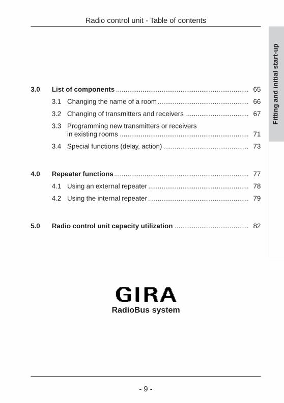
3.0 List of components ...................................................................... 65
3.1 Changing the name of a room................................................ 66
3.2 Changing of transmitters and receivers ................................. 67
3.3 Programming new transmitters or receiversin existing rooms .................................................................... 71
3.4 Special functions (delay, action) ............................................. 73
4.0 Repeater functions ....................................................................... 77
4.1 Using an external repeater ..................................................... 78
4.2 Using the internal repeater ..................................................... 79
5.0 Radio control unit capacity utilization ....................................... 82
Radio control unit - Table of contents
Fit
tin
g a
nd
init
ial s
tart
-up
RadioBus system

- 10 -
1.0 Fitting and initial start-up
1.0 Fitting and initial start-up
Safety warning
Attention!Electrical appliances must be fitted and installedby qualified electricians only.
1.1 Scope of supply
The scope of supply of the radio control unit includes:
• 1 radio control unit• 1 mains connection cord• 1 drill template• 1 fitting set with 3 screws and plugs• 1 manual with 1 radio control unit Mastercard
To ensure operation of the radio control unit in the event of mains failures,the device must be equipped in addition with 5 Micro batteries (type: AAA1.5 V LR 03). The batteries also facilitate the programming procedures fortransmitters and receivers.
1.2 Selecting the fitting location
For optimal viewing of the radio control unit display, it is recommended toinstall the device at the customer’s eye level.
As the transfer of information between the radio control unit and theprogrammed transmitters and receivers is ensured by radio waves, thefollowing points should be observed when selecting the fitting location:
Fit
tin
g a
nd
init
ial s
tart
-up

- 11 -
1.0 Fitting and initial start-up
- In order to protect the radio transmission against interference from otherelectrical appliances, the device should be installed at an approximatedistance of 0.5 m from other electrical consumers (e.g. microwave oven,HiFi and TV equipment).
- To ensure optimal radio transmission, the fitting location should also be ata sufficient distance from large metal pieces (e.g metallic door frames orcupboards).
- Select an easily accessible, central location inside your radio control systemand make sure that all components of the radio system can be safelyreached. Observe also the instructions set out in chapters 1.2.1 and 1.2.2.
1.2.1 Information on the operation of radio equipment
- The inter-connection of this radio system with other communicationnetworks must comply with national legislation.
- This radio system must not be used for communication beyond propertyboundaries.
- Operation in Germany is subject to the relevant regulations of AmtsblattVfg 73/2000.
- If utilized in conformity with its designated use, this unit fulfills therequirements of the R&TTE Directive (1999/5/EG). The complete declarationof conformity can be found in the Internet under: www.gira.de/konformitaet
The radio control unit may be operated in all countries of the EU andthe EFTA.
Fit
tin
g a
nd
init
ial s
tart
-up

- 12 -
1.2.2 Radio transmission
Radio transmission takes place on non-exclusive frequencies.Interference can therefore not be excluded. This type of radio transmissionis not suitable for safety applications such as emergency shut-off oremergency calling functions.
The range of a radio system depends on transmitter output power, receivercharacteristics, humidity of the air, installation height and on local buildingconditions. Some examples for radio wave penetration in building materials:
Material PenetrationTimber, gypsum, gypsum plaster-boards approx. 90 %Brickwork, press-boards approx. 70 %Reinforced concrete approx. 30 %Metal, metal grating, aluminium approx. 10 %Rain, snow approx 0-40 %
Fig. 1.a: Material penetration
1.2.2 Radio transmission
Fit
tin
g a
nd
init
ial s
tart
-up
- 13 -
1.3 Fitting
Fit
tin
g a
nd
init
ial s
tart
-up1.3 Fitting
Safety warnings
AttentionElectrical appliances must be installed and fittedonly by qualified electricians.
Important
• Before fitting the radio control unit it isrecommended to program the radio controltransmitters and receivers already existing intoyour radio control unit beforehand. Read theinformation in chapter 2.0 "Initial start-up".
• When selecting a suitable location for the unit,observe also the information provided in chapter2.1 "Setting the time" in order to ensure optimalreception of the DCF77 time standard signals.
• For easy reading of the display, the radio controlunit should not be installed in direct sunlight.
The radio control unit can be installed as stand-alone unit, but can also beintegrated into the modular function console. For installing individual units onthe surface, a fitting frame is required.
- 14 -
1.3 Fitting
Fit
tin
g a
nd
init
ial s
tart
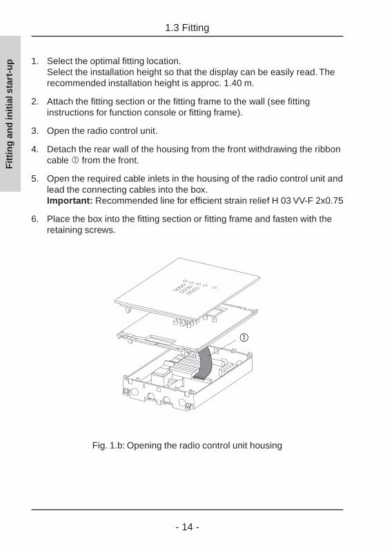
-up 1. Select the optimal fitting location.
Select the installation height so that the display can be easily read. Therecommended installation height is approc. 1.40 m.
2. Attach the fitting section or the fitting frame to the wall (see fittinginstructions for function console or fitting frame).
3. Open the radio control unit.
4. Detach the rear wall of the housing from the front withdrawing the ribboncable from the front.
5. Open the required cable inlets in the housing of the radio control unit andlead the connecting cables into the box.Important: Recommended line for efficient strain relief H 03 VV-F 2x0.75
6. Place the box into the fitting section or fitting frame and fasten with theretaining screws.
Fig. 1.b: Opening the radio control unit housing

- 15 -
1.3 Fitting
Fit
tin
g a
nd
init
ial s
tart
-up7. Remove the terminal box by loosening screw .
8. Remove the insulation of the connecting cables.
9. Open the strain-relief clamp .
10. Lead the cable through the inlet into the housing and connect toterminal .
11. Close the strain-relief clamp and screw the terminal box back in place.Important: Make sure the cable jacket reaches into the terminal box .
12. Replug the ribbon cable into the connector in the front part of thehousing.Make sure the connector is plugged in properly.
13. Put the base-plate on the housing and fasten it with the four screws tothe fitting section or the fitting frame.
14. Install the glass cover and press until the retaining clips engage.
Fig. 1.c: Connection of mains supply line

- 16 -
Fitting and initial start-up

- 17 -
1.4 Removal of the front cover
Fit
tin
g a
nd
init
ial s
tart
-up1.4 Removal of the front cover
To remove, withdraw the glass front cover forwards using both hands (seeillustration).
Fig. 1.d: Removal of the glass front

- 18 -
Fit
tin
g a
nd
init
ial s
tart
-up 1.5 Inserting or replacing the batteries
To ensure operation of the radio control unit in the event of mains failures, thedevice must be equipped with 5 Micro cell batteries (type: AAA 1.5 V LR 03).The batteries also facilitate the programming procedures for transmitters andreceivers.
The battery charge is indicated by the battery symbol (21) on the standarddisplay. More information on this subject can be found in chapter 1.2 "Thestandard display".
Safety warnings and disposal instructions
Attention: Batteries must not get into the hands ofchildren. Remove used batteries immediately anddiscard without polluting the environment. Replacebatteries only by batteries of the same type.
After opening of the radio control unit there is arisk of accidental contact with exposed live wiresand of electric shocks. Therefore, pull the mainscord of the unit out of the socket or cut out therespective circuit breaker.
General information
- Do not use rechargeable batteries. They have alower capacity than primary batteries.
- During normal operation of the radio control unitwith mains voltage, no power is drained from thebatteries.
- With new batteries, the radio control unit can besupplied with power in the event of mains failuresfor about 6 hours.
1.5 Inserting or replacing the batteries
- 19 -
Fit
tin
g a
nd
init
ial s
tart
-up
1.5 Inserting or replacing the batteries
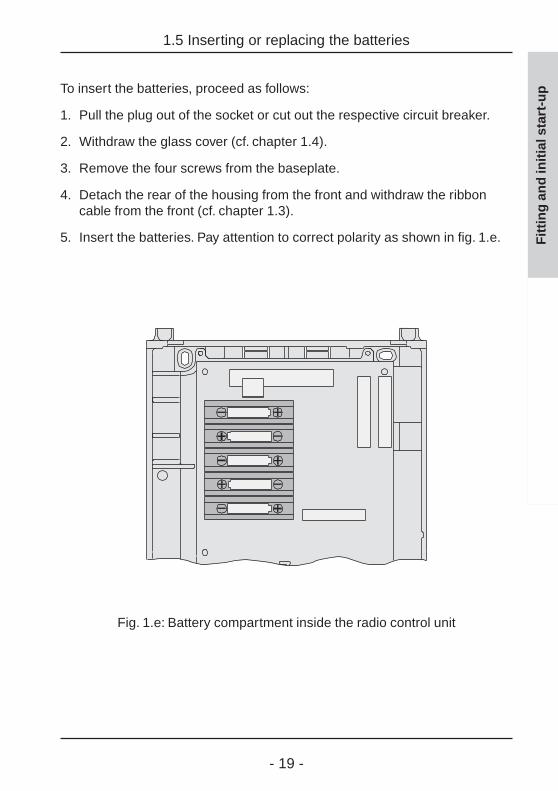
To insert the batteries, proceed as follows:
1. Pull the plug out of the socket or cut out the respective circuit breaker.
2. Withdraw the glass cover (cf. chapter 1.4).
3. Remove the four screws from the baseplate.
4. Detach the rear of the housing from the front and withdraw the ribboncable from the front (cf. chapter 1.3).
5. Insert the batteries. Pay attention to correct polarity as shown in fig. 1.e.
Fig. 1.e: Battery compartment inside the radio control unit

- 20 -
2.0 Initial start-up
At first please make yourself familiar with the use ofthe radio control unit menu. Detailed instructions areset out in chapter 1.0 "Introduction“ of the manualand especially in 1.3 "Directions for use".
It is recommended to operate the radio control unitduring initial start-up with batteries as the radio controlunit must be operated for programming purposes withina radius of 5 m from your radio control appliances. Donot forget that for energy saving purposes the displaybacklighting is always off during battery operation.
To facilitate the initial start-up, you will be guidedautomatically through the first steps by an initial start-up assistant afterconnecting the power supply (batteries or mains). The assistant will guideyou through the following start-up dialogs:
1. Setting the time (chapter 2.1)
2. Integrating an external repeater (chapter 2.2)
3. Programming of radio control receveirs (chapter 2.3)
4. Programming of radio control transmitters (chapter 2.4)
5. Setting up time-controlled programs (chapter 2.5)
6. Setting up logic links (chapter 2.6)
If you have already stored data in the radio control unit, the initial start-upassistant is not started automatically. It can nevertheless be used for furtherentries and can be activated in the radio control unit menu under"Configuration – Initial start-up". The initial start-up will then begin withscreen 2.0.2.
2.0 Initial start-up
Fit
tin
g a
nd
init
ial s
tart
-up

- 21 -
For initial start-up, please follow the instructions of the initial start-upassistant on the display of the radio control unit:
2.0.1Confirm the opening screen with "Next"
2.0.2Confirm the following info screen with "Next"."Abort" returns to the main menu.
2.0.3To enter into the start-up dialog "Setting thetime", press "Yes". Continue with chapter 2.1."No" takes you to the next start-up dialog (inthis case: "Repeater").
2.0 Initial start-up
Fit
tin
g a
nd
init
ial s
tart
-up

- 22 -
2.1 Setting the time
The radio control unit is equipped with a DCF77 radio receiver. Within aradius of about 1500 km from the time signal transmitter (DCF77) inFrankfurt, Germany, the date and time display can be synchronized with thesignal from this station. The advantage of using the DCF77 time signal isthat the time of day is always correct without any manual correction beingneeded.
To determine the field strength of the DCF77 signal when setting the time,the radio control unit is equipped with a field strength indicator (cf. fold-outpage (12).The quality of the DCF77 signal received is indicated by the field strengthindicator as a figure between 0 and 5:
0, 1, 2: DCF77 reception is insufficient.3: DCF77 can be received only with restrictions.4: DCF77 reception is good.5: DCF77 reception is very good.
The first synchronizing procedure may last between 2 and 15 minutes. Whenthe clock is synchronized, the field strength indicator is no longer displayed.
If the reception of the DCF77 time signal is not possible, the time must beset by hand. In this case, the clock runs with quartz precision.
The setting of date and time can be effected with the help of the start-updialog "Setting the time" which is part of the initial start-up assistant.
To set the time and date after initial start-up, the start-up dialog "Setting thetime" can also be called up directly in the main menu under "Configuration -System – Setting the time".
To set the time, follow the dialog instructions on the display of the radiocontrol unit.
2.1 Setting the time
Fit
tin
g a
nd
init
ial s
tart
-up

- 23 -
2.1 Setting the time
Fit
tin
g a
nd
init
ial s
tart
-up2.1.1
When DCF reception is possible, select here"DCF on" (continue with 2.2.1) otherwiseselect "DCF off" (continue with 2.1.2)."Back" returns to the previous screen.
2.1.2If "DCF off" is selected, the date must be sethere. The weekday is set automatically. Setthe date directly with the numerical keys. With" =" and " > " the date can be changed by theday either slowly (brief press) or fast (longpress).Confirm your selection with "Ok"."Back" returns to the previous screen.
2.1.3Set the time directly using the numerical keys.With " =" and " > " the time can be changedby the minute either slowly (brief press) or fast(long press).Conform your selection with "Ok"."Back" returns to the previous screen.
If the start-up dialog "Setting the time" had been called up directly fromwithin the menu, "Ok" will take you back to the menu.
If you are within the initial start-up, "Ok" continues with the integration of anexternal repeater. Continue with chapter 2.2.
- 24 -
2.2 Integrating an external repeater
Fit
tin
g a
nd
init
ial s
tart
-up 2.2 Integrating an external repeater
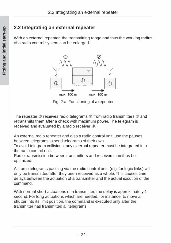
With an external repeater, the transmitting range and thus the working radiusof a radio control system can be enlarged.
Fig. 2.a: Functioning of a repeater
The repeater receives radio telegrams from radio transmitters andretransmits them after a check with maximum power. The telegram isreceived and evaluated by a radio receiver .
An external radio repeater and also a radio control unit use the pausesbetween telegrams to send telegrams of their own.To avoid telegram collisions, any external repeater must be integrated intothe radio control unit.Radio transmission between transmitters and receivers can thus beoptimized.
All radio telegrams passing via the radio control unit (e.g. for logic links) willonly be transmitted after they been received as a whole. This causes timedelays between the actuation of a transmitter and the actual excution of thecommand.
With normal short actuations of a transmitter, the delay is approximately 1second. For long actuations which are needed, for instance, to move ashutter into its limit position, the command is executed only after thetransmitter has transmitted all telegrams.

- 25 -
2.2.1Confirm the info text with "Next"."Abort" returns to the main menu.
2.2.2If you do not use a repeater in your radiocontrol system, select "No", or otherwise"Yes".
An external repeater can also be integrated later into the radio control unit.To do so, select "Configuration - System - Repeater" in the menu. Moreover,the radio control unit itself can also be used as a repeater. Read chapter 4 ofthe fitting and start-up instructions.
In the initial start-up, the next dialog is the start-up dialog "new receiver"(screen 2.2.3).
2.2.3To launch the start-up dialog "new receiver",press "Yes". Continue reading in chapter 2.3."No" takes you to the next start-up dialog(here: "new receiver").
2.2 Integrating an external repeater
Fit
tin
g a
nd
init
ial s
tart
-up

- 26 -
2.3 Programming of radio control receivers
In order to integrate your existing radio control unit (e.g. switching, dimmingand shutter actuators) into time-controlled programs of the radio control unit,the radio control unit must be programmed into these radio control receivers.
This is done with the start-up dialog "new receiver" which is part of the initialstart-up assistant.
For adding further radio control receivers after initial start-up, the "newreceiver" start-up dialog can also be called up directly from the main menuunder "Configuration – Components – New receiver".
Since the radio control unit and the radio controlreceiver must not be farther apart than 5 m from eachother for programming, it is recommended to operatethe radio control unit with batteries. Do not forget thatfor energy saving purposes the display backlighting isalways off during battery operation.
To program radio control receivers, follow the dialog instructions on thedisplay of the radio control unit.
2.3 Programming of radio control receivers
Fit
tin
g a
nd
init
ial s
tart
-up

- 27 -
2.3.1Confirm the info text for receiver programmingwith "Next"."Abort" returns to the main menu.
2.3.2Select at first a room for the receiver. Thenconfirm the info text with "Next"."Abort" returns to the main menu.
2.3.3Select a room from the room list (continue with2.3.7) or add a new room. To add a new room,select <new room > (continue with 2.3.4)."Back" returns to the previous screen.
2.3.4If you have selected <new room >, you cangive the room a name.Confirm the info text with "Next"."Back" returns to the previous screen.
2.3.5Select a room name from the list or select<new name> in order to add a new roomname. Confirm your selection with "Select"."Back" returns to the previous screen.
2.3 Programming of radio control receivers
Fit
tin
g a
nd
init
ial s
tart
-up

- 28 -
2.3.6In this screen, the selected room name can beedited or the new room name entered. Thename may consist of up to 16 characters.For entering text, use the keypad (see fold-outpage (3))."Abc" shifts between capital and small letters."<-" deletes the last character.When you have entered a room name, confirmwith "Ok"."Back" returns to the previous screen.
2.3.7Confirm the info text with "Next""Back" returns to the previous screen.
2.3.8Select the type of your radio control receiverfrom the following list. Confirm with "Select".The receivers above the broken line arereceiver types that have already beenprogrammed (here: none)."Back" returns to the previous screen.
2.3.9In the example above, a dimming actuator wasselected. Confirm the following info screenwith "Next"."Back" returns to the previous screen.
2.3 Programming of radio control receivers
Fit
tin
g a
nd
init
ial s
tart
-up
- 29 -
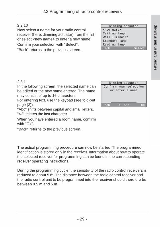
2.3.10Now select a name for your radio controlreceiver (here: dimming actuator) from the listor select <new name> to enter a new name.Confirm your selection with "Select"."Back" returns to the previous screen.
2.3.11In the following screen, the selected name canbe edited or the new name entered. The namemay consist of up to 16 characters.For entering text, use the keypad (see fold-outpage (3))."Abc" shifts between capital and small letters."<-" deletes the last character.When you have entered a room name, confirmwith "Ok"."Back" returns to the previous screen.
The actual programming procedure can now be started. The programmedidentification is stored only in the receiver. Information about how to operatethe selected receiver for programming can be found in the correspondingreceiver operating instructions.
During the programming cycle, the sensitivity of the radio control receivers isreduced to about 5 m. The distance between the radio control receiver andthe radio control unit to be programmed into the receiver should therefore bebetween 0.5 m and 5 m.
2.3 Programming of radio control receivers
Fit
tin
g a
nd
init
ial s
tart
-up

- 30 -
2.3.12Bring the radio control unit to within a radius of5 m from your radio control receiver andswitch the receiver into the programmingmode (see radio receiver operatinginstructions).Confirm with "Next". The radio control unitstarts sending programming telegrams."Back" returns to the previous screen.
2.3.13Check whether the radio control receiver hasconfirmed the programming procedure (seeradio receiver operating instructions). In theabsence of a confirmation, the programmingcycle can be repeated from step 2.3.12onwards by pressing "No".
2.3.14Quit the receiver programming mode. (seeradio receiver operating instructions) and thenconfirm with "OK".
2.3.15The programming procedure for this radiocontrol receiver is now terminated. If you wantto program another receiver, press "Yes" andthe programming procedure begins again withstep 2.3.2.
2.3 Programming of radio control receivers
Fit
tin
g a
nd
init
ial s
tart
-up

- 31 -
If you have called up the "new receiver" start-up dialog directly from withinthe menu, pressing "No" takes you back to the menu.
If you are within the initial start-up, pressing "No" now launches the "newtransmitter" start-up dialog (step 2.3.16).
2.3.16To launch the "new transmitter" start-updialog, press "Yes". Continue reading inchapter 2.4."No" takes you to the next start-up dialog(here: "new program").
To change or to delete a programmed radio controlreceiver, read chapter 3.2 "Changing transmitters andreceivers" of the present fitting and start-up instructions.
2.3 Programming of radio control receivers
Fit
tin
g a
nd
init
ial s
tart
-up

- 32 -
2.4 Programming of radio control transmitters
All radio control transmitters (e.g. hand-held or wall-mounted transmitters) towhich functions are assigned via logic linking in the radio control unit, mustbe programmed into the radio control unit.
This is done with the start-up dialog "new transmitter" which is part of theinitial start-up assistant.
For adding further radio control transmitters after initial start-up, the "newtransmitter" start-up dialog can also be called up directly from the mainmenu under "Configuration – Components – New transmitter".
Since the radio control unit and the radio controltransmitter must not be farther apart than 5 m fromeach other for programming, it is recommended tooperate the radio control unit with batteries. Do notforget that for energy saving purposes the displaybacklighting is always off during battery operation.
To program radio control transmitters, follow the dialog instructions on thedisplay of the radio control unit.
2.4 Programming of radio control transmitters
Fit
tin
g a
nd
init
ial s
tart
-up
- 33 -
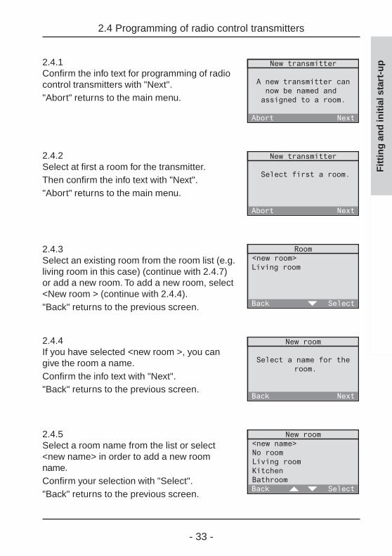
2.4.1Confirm the info text for programming of radiocontrol transmitters with "Next"."Abort" returns to the main menu.
2.4.2Select at first a room for the transmitter.Then confirm the info text with "Next"."Abort" returns to the main menu.
2.4.3Select an existing room from the room list (e.g.living room in this case) (continue with 2.4.7)or add a new room. To add a new room, select<New room > (continue with 2.4.4)."Back" returns to the previous screen.
2.4.4If you have selected <new room >, you cangive the room a name.Confirm the info text with "Next"."Back" returns to the previous screen.
2.4.5Select a room name from the list or select<new name> in order to add a new roomname.Confirm your selection with "Select"."Back" returns to the previous screen.
2.4 Programming of radio control transmitters
Fit
tin
g a
nd
init
ial s
tart
-up

- 34 -
2.4.6In this screen, the selected room name can beedited or the new room name entered. Thename may consist of up to 16 characters.For entering text, use the keypad (see fold-outpage (3))."Abc" shifts between capital and small letters."<-" deletes the last character. When you haveentered a room name, confirm with "Ok"."Back" returns to the previous screen.
2.4.7Confirm the info text with "Next"."Back" returns to the previous screen.
2.4.8Select the type of your radio controltransmitter from the following list.Confirm with "Next".The transmitters above the broken line aretransmitter types that have already beenprogrammed (here: none)."Back" returns to the previous screen.
2.4.9In the example above, a hand-held transmitterwas selected.Confirm the following info screen with "Next"."Back" returns to the previous screen.
2.4 Programming of radio control transmitters
Fit
tin
g a
nd
init
ial s
tart
-up

- 35 -
2.4.10Now select a name for your radio controltransmitter (here: hand-held transmitter) fromthe list or select <New name> to define a newname.Confirm your selection with "Select“.
2.4.11In the following screen, the selected name canbe edited or the new name entered. The namemay consist of up to 16 characters.For entering text, use the keypad (see fold-outpage (3))."Abc" shifts between capital and small letters."<-" deletes the last character. When you haveentered a room name, confirm with "Ok"."Back" returns to the previous screen.
The actual programming procedure can now be started. The programmedidentification is stored only in the receiver.
To change or to delete a programmed radio controlreceiver, read chapter 3.2 "Changing transmitters andreceivers" of the present fitting and start-up instructions.
2.4 Programming of radio control transmitters
Fit
tin
g a
nd
init
ial s
tart
-up

- 36 -
2.4 Programming of radio control transmitters
Fit
tin
g a
nd
init
ial s
tart
-up 2.4.12
During programming of a radio control transmitter,the sensitivity of the radio control unit is reducedto about 5 m. The distance between the radiocontrol transmitter and the radio control unitshould therefore be between 0.5 m and 5 m."Back" returns to the previous screen.
2.4.13Start sending a programming telegram fromyour transmitter (see radio control transmitteroperating instructions). If the radio control trans-mitter is identified, the radio control unitautomatically changes over to the next screen(2.4.14). If the transmitter was already programmedbefore, the radio control unit remains in thisscreen.
2.4.14"Yes" adds the identified transmitter to the listof transmitters. "No" rejects the identifiedtransmitter and takes you back to step 2.4.12.
2.4.15The transmitter is now programmed in theradio control unit. If you want to programanother radio control transmitter, press "Yes"and the programming procedure for a newtransmitter begins again with step 2.4.2.
- 37 -
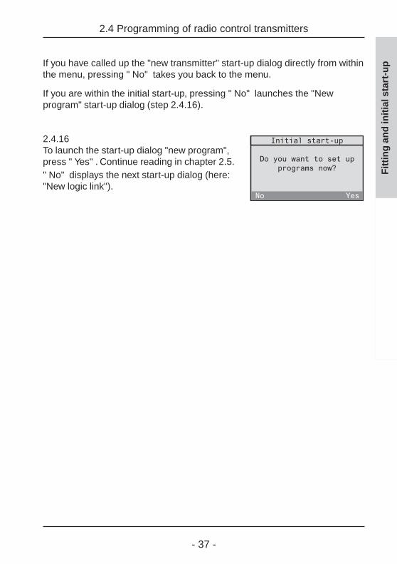
If you have called up the "new transmitter" start-up dialog directly from withinthe menu, pressing " No" takes you back to the menu.
If you are within the initial start-up, pressing " No" launches the "Newprogram" start-up dialog (step 2.4.16).
2.4.16To launch the start-up dialog "new program",press " Yes" . Continue reading in chapter 2.5." No" displays the next start-up dialog (here:"New logic link").
2.4 Programming of radio control transmitters
Fit
tin
g a
nd
init
ial s
tart
-up

- 38 -
2.5 Setting up time-controlled programs
Programs can be used to assign tasks consisting of certain actions to beperformed at specified times to your previously programmed radio controlreceivers.
Programs are set up with the help of the start-up dialog "new program"which is part of the initial start-up assistant.
For setting up new programs after initial start-up, the start-up dialog "newprogram" can also be called up directly from the main menu under"Configuration – Programs – <New program>".
To set up time-controlled programs, follow the dialog instructions on thedisplay of the radio control unit.
2.5 Setting up time-controlled programs
Fig. 2.b:Program entry sequence
Fit
tin
g a
nd
init
ial s
tart
-up

- 39 -
Fit
tin
g a
nd
init
ial s
tart
-up
2.5 Setting up time-controlled programs
Astro time
The switching times stored in your programs can – if necessary – beautomatically adapted to the astro time (sunset and/or sunrise times duringthe year). A distinction is made between switching times for blinds/shuttersand lighting.
WZ:Central European winter timeSZ: Central European summer
time (winter + 1 h)
Fig. 2.c:Astro switching times over theyear (approx. location: Würzburg)
When the astro function is active, the switching times will be shifted as follows:
Blind/shutter:
Switching times in the morning falling into darkness will be executed at thetime of sunrise (astro morning curve).
Switching times in the evening falling into darkness will be executed at thetime of sunset (astro evening curve).

- 40 -
Fit
tin
g a
nd
init
ial s
tart
-up
2.5 Setting up time-controlled programs
Example for blinds/shutters:
MON - SUN: 06:30 h shutter raisedMON - SUN: 19:10 h shutter lowered
The shutter is raised in the morning at sunset – but not before 6:30 h – andis lowered in the evening at sunset – but not later than 19:10 h..
Lighting:
Switching times in the morning falling into daylight are executed already atthe time of sunrise (astro morning curve).
Switching times in the evening falling into daylight are executed only at thetime of sunset (astro evening curve).
Example for lighting:
MON - SUN: 09:00 h lights switched offMON - SUN: 16:15 h lights switched on
Both times fall into daylight during the whole year; this means that not theswitching times indicated, but rather the astro times will be executed.
Important information:Switching times valid for blinds/shutters and also forlighting (type: all) will be handled in the astro mode asshutter switching times.
Fig. 2.d:Astro function example forshutter moving actions

- 41 -
Fit
tin
g a
nd
init
ial s
tart
-up
2.5 Setting up time-controlled programs
Astro time-shift
The astro time-shift permits adapting the factory-adjusted surise and sunsettimes (cf. fig. 2.c) to individual local conditions. The maximum shift of ± 120 minis performed for all days of the year.
Example 1:
The veranda is located at the southwest side of the house. Since the sun sets inthe west, it will get dark there a little later. The astro time for sunset can thereforebe shifted slightly forwards (e.g. + 0:50 shutter lowered 50 min later)
Example 2:
On a slope at the east side of the house it will get dark earlier than fixed by theastro curve. The astro time for sunset can therefore be shift slightly backwards(e.g. - 0:20 shuuter lowered 20 min earlier).

- 42 -
2.5 Setting up time-controlled programs
Fit
tin
g a
nd
init
ial s
tart
-up Procedure for setting up time-controlled programs
2.5.1Confirm the info text for setting up a newprogram with "Next"."Abort" returns to the main menu.
2.5.2At first, the program must be given a name.Confirm the info text "Next"."Abort" returns to the main menu.
2.5.3Select a new name for the program from thelist or select <new name> to define a newprogram name.Confirm your selection with "Select"."Back" returns to the previous screen.
2.5.4In this screen, the selected room name can beedited or the new room name entered. Thename may consist of up to 16 characters.For entering text, use the keypad (see fold-outpage (3))."Abc" shifts between capital and small letters."<-" deletes the last character.When you have entered a room name, confirmwith "Ok"."Back" returns to the previous screen.

- 43 -
2.5.5Confirm the info text for the astro function with"Next"."Back" returns to the previous screen.
2.5.6If you want to use the astro function in thisprogram, confirm with "Yes". The astrofunction can then still be added later on forindividual switching times (continue withscreen 2.5.7).If you do not want to use the astro function inthis program, press "No" (continue with2.5.10).
2.5.7In this step, the astro time-shifts for morningand evening can be set. Confirm the info textwith "Next"."Back" returns to the previous screen.
2.5.8Set the shift for the morning directly with thenumerical keys or with ">" and "=". The signcan be changed with the "*" and also with the"#" key. The maximum admissible shift is± 120 min. Confirm your selection with "Ok".
2.5.9The next screen is an info screen for the astrotime-shift in the evening. Confirm with "Next".Then, set the shift for the evening asdescribed under 2.5.8.
2.5 Setting up time-controlled programs
Fit
tin
g a
nd
init
ial s
tart
-up

- 44 -
2.5.10In the next step, you can fix the weekdays onwhich the desired action is to be performed.The action (e.g. activating the switchingactuator or raising the shutter) is determinedat the end of this dialog.Confirm the info text with "Next"."Back" returns to the previous screen.
2.5.11Select now a predefined weekday combination(in this case: Mo to Fr). The selection can stillbe changed in the following screen. If youwant to define the days freely, select "Other".Confirm your selection with "Select"."Back" returns to the previous screen.
2.5.12This screen displays the weekdaycombination. Selected days are shownunderlined (in this case: Mo to Fr). If you wantto change this combination, you can move thecursor in the weekday display with "<-" and"->" and add or remove a day to or from theweekday combination with "Select".If the underlinded days correspond to thedesired combination, place the cursor on "Ok"and confirm with "Select".
2.5.13In the next step, you can fix the time of day atwhich the action is to be performed. Confirmthe info text with "Next"."Back" returns to the previous screen.
2.5 Setting up time-controlled programs
Fit
tin
g a
nd
init
ial s
tart
-up

- 45 -
2.5 Setting up time-controlled programs
2.5.14Set the time directly using the numerical keys.The time can alternatively also be changed bythe minute with "=" and ">" slowly (brief presson the key) or fast (long press on the key).Confirm your selection with "Ok"."Back" returns to the previous screen.
2.5.15Only if the astro function has been activatedfor this programm (cf. screen 2.5.6) can theastro function for the previously selectedswitching time be enabled with "Yes" ordisabled with "No".
2.5.16In the next step, select the room and thepertaining receiver which is to perform theaction.Confirm the info text with "Next"."Back" returns to the previous screen.
2.5.17Select now the room in which the desiredreceiver is located (in this case: kitchen). Youcan also select "Central function". Thisfunction permits controlling several actuatorsof the same type in different rooms."Back" returns to the previous screen.
Fit
tin
g a
nd
init
ial s
tart
-up
- 46 -
2.5 Setting up time-controlled programs
Fit
tin
g a
nd
init
ial s
tart
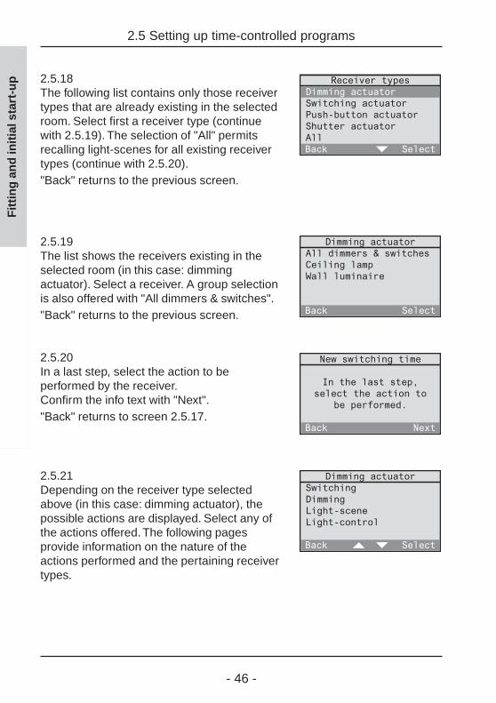
-up 2.5.18
The following list contains only those receivertypes that are already existing in the selectedroom. Select first a receiver type (continuewith 2.5.19). The selection of "All" permitsrecalling light-scenes for all existing receivertypes (continue with 2.5.20)."Back" returns to the previous screen.
2.5.19The list shows the receivers existing in theselected room (in this case: dimmingactuator). Select a receiver. A group selectionis also offered with "All dimmers & switches"."Back" returns to the previous screen.
2.5.20In a last step, select the action to beperformed by the receiver.Confirm the info text with "Next"."Back" returns to screen 2.5.17.
2.5.21Depending on the receiver type selectedabove (in this case: dimming actuator), thepossible actions are displayed. Select any ofthe actions offered. The following pagesprovide information on the nature of theactions performed and the pertaining receivertypes.

- 47 -
Description of performed actions
Important information:If you program also a special function for the receiver,it is possible that after performing the action described,the receiver will moreover perfom a special function.Read also chapter 3.4 "Special functions".
Switching (only with: switching and dimming actuators)
On / OffThe selected receiver is switched on and off.
Dimming (only with: dimming actuators)
Dimming levelThe dimming actuator can be dimmed to acertain brightness level. Adjust the brightnesslevel directly with the numerical keys or with"=" and ">".When "Ok" is pressed for the first time, thebrightness level is set in the assigned receiverfor visual checking.When "Ok" is pressed a second time, thebrightness level is definitely stored and thescreen terminated."Back" returns to the previous screen.
2.5 Setting up time-controlled programs
Fit
tin
g a
nd
init
ial s
tart
-up
- 48 -
Momentary contact function (only with: push-button actuators)
ActuateA press on the selected push-button actuator transmits a single pulse.
Light-scene (only with: switching, dimming, shutter actuators and All)
Light-scene 1-5The lamps are set to the value of the recalled light-scene. With shutters,only one of the two limit positions can be stored in a light-scene.
All-ON / All-OFFThe All-ON resp. the All-OFF function is executed in the selected receiver.
Shutter (only with: shutter actuators)
Limit position – top / bottomThe selected shutter is moved to the upper or lower position.
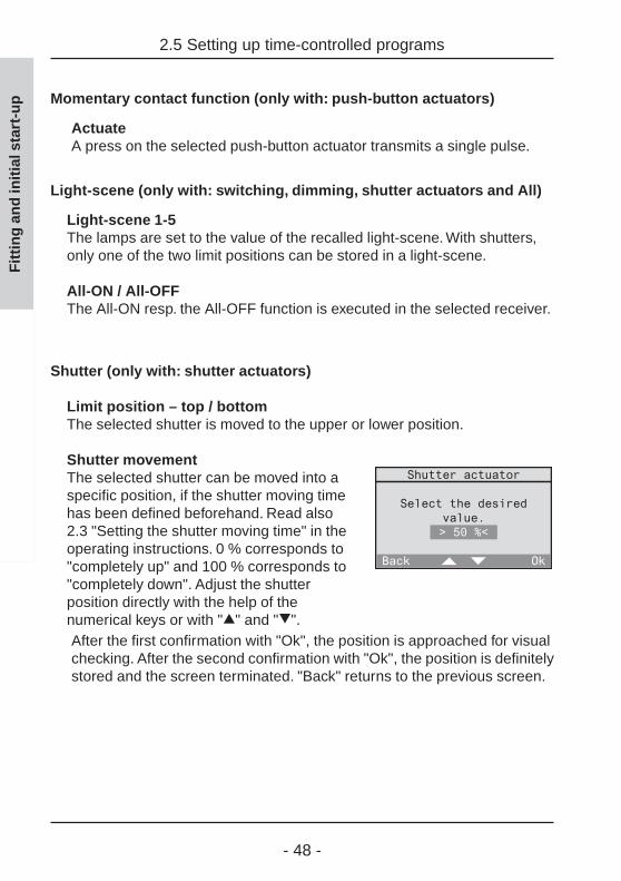
Shutter movementThe selected shutter can be moved into aspecific position, if the shutter moving timehas been defined beforehand. Read also2.3 "Setting the shutter moving time" in theoperating instructions. 0 % corresponds to"completely up" and 100 % corresponds to"completely down". Adjust the shutterposition directly with the help of thenumerical keys or with "=" and ">".After the first confirmation with "Ok", the position is approached for visualchecking. After the second confirmation with "Ok", the position is definitelystored and the screen terminated. "Back" returns to the previous screen.
2.5 Setting up time-controlled programs
Fit
tin
g a
nd
init
ial s
tart
-up
- 49 -
Presence (only with: All)
LeavingThe last brightness values of the lighting and the shutter end positions arestored before the All-Off telegram is transmitted.
ReturningDepending on the defined special functions (delay, action) of the radiocontrol receiver, 3 types of reactions are available:- Delay: 0 min; action: <none>
The value stored before leaving is restored on returning. Observe alsothe information in chapter 3.4.
- Delay: 0 min; action: definedThe defined action is performed on return.
- Delay: > 0 min; action: definedAt first, the value stored before leaving is restored on returning. Thedefined action is then performed at the end of the delay.
Read also chapter 5.2 "The leaving / returning function" in the operatinginstructions.
Light control (only with: switching and dimming actuators)
Light control on /offIf a radio control presence detector has been programmed into thereceiver, the light control can be activated or deactivated here. Any otheraction transmitted by the radio control unit deactives an active lightcontrol.
Adopting the lux valueIf a radio presence detector has been programmed into the selectedreceiver, the actual brightness value can be stored in the actuator asbrightness reference value (lux value) for the light control function.
2.5 Setting up time-controlled programs
Fit
tin
g a
nd
init
ial s
tart
-up
- 50 -
2.5 Setting up time-controlled programs
Fit
tin
g a
nd
init
ial s
tart
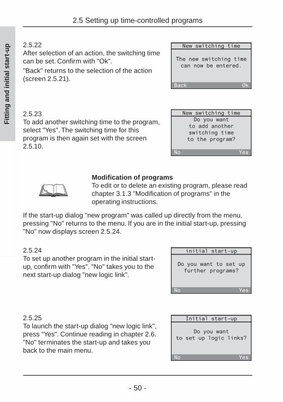
-up 2.5.22
After selection of an action, the switching timecan be set. Confirm with "Ok"."Back" returns to the selection of the action(screen 2.5.21).
2.5.23To add another switching time to the program,select "Yes". The switching time for thisprogram is then again set with the screen2.5.10.
Modification of programsTo edit or to delete an existing program, please readchapter 3.1.3 "Modification of programs" in theoperating instructions.
If the start-up dialog "new program" was called up directly from the menu,pressing "No" returns to the menu. If you are in the initial start-up, pressing"No" now displays screen 2.5.24.
2.5.24To set up another program in the initial start-up, confirm with "Yes". "No" takes you to thenext start-up dialog "new logic link".
2.5.25To launch the start-up dialog "new logic link",press "Yes". Continue reading in chapter 2.6."No" terminates the start-up and takes youback to the main menu.

- 51 -
2.6 Setting up logic links
A logic link can be used to control a receiver from a transmitter via the radiocontrol unit. This logic link can be set up in such a way that it is dependenton time and/or the status of another transmitter.
Example 1:The switching actuator in the study can only be switched from the hand trans-mitter, if wall transmitter channel 1 in the hallway is activated (central function).As another condition, switching is to be possible only from Monday thru Fridaybetween 18:00h and 23:00h.
Example 2:The smoke detector is to switch on the light in the bedroom via the radiocontrol unit in the event of smoke alarm.
The following description makes use of different terms which are definedhere with reference to example 1:
Receiver (logic link): in this case switching actuator in the study
A logic link includes a receiver which can perform an action defined by acontrol set. Each receiver can be assigned several control sets which arelinked by a logic OR.
Control set:The term „control set“ includes the following elements:
Time (time of day and weekdays) Condition (state of transmitter) Initiator (transmitter) Action (only with presence detector or monitor)
Time: in this case Monday thru Friday between 18:00h and 23:00h
The weekdays and the duration during which the logic link can beactivated. If starting and ending time are set to 00:00h, the duration istaken as a full day (24 hours).
2.6 Setting up logic links
Fit
tin
g a
nd
init
ial s
tart
-up
- 52 -
Condition (transmitter status): in this case wall transmitter channel 1 active
The receiver can only be activated if the condition is fulfilled. A conditionalways implies a certain transmitter status.A logic link must not necessarily include a condition.
Initiator (transmitter): in this case hand transmitter
The transmitter triggering an action in your receiver, if time requirementsand, if applicable, also the condition are fulfilled.
Action:If a presence detector or a monitor has been selected as an initiator(transmitter), the action to be performed can also be chosen freelydepending on the type of receiver.In all other cases (e.g. channel key or light-scene of a hand transmitter)no action can be chosen, as the key-specific function will be executed.
Important information
• The "dimming" and "slat adjustment" functions arenot supported by logic links. The dimming level orshutter position functions can be used instead.
• The "All-On" and "All-Off" keys should not be usedas initiator or condition as the long transmit times(up to about 12 seconds) may cause delayedreactions.
2.6 Setting up logic links
Fit
tin
g a
nd
init
ial s
tart
-up

- 53 -
Logic links are set up with the help of the "new logic link" start-up dialogwhich is part of the initial start-up assistant.
To set up further new logic links even after the initial start-up, the "new logiclink" start-up dialog can also be called up directly in the main menu under"Configuration – Logic link – <new logic link>".
To set up logic links, follow the dialog instructions on the display of the radiocontrol unit.
2.6 Setting up logic links
Fig. 2.e:Logic link entry sequence
Fit
tin
g a
nd
init
ial s
tart
-up

- 54 -
2.6.1Confirm the info text for setting up a new logiclink with "Next"."Abort" returns to the main menu.
2.6.2The logic link must first be given a name.Confirm the info text with "Next"."Abort" returns to the main menu.
2.6.3Select a new name for the logic link from thelist or select <new name> to define a newname for the logic link. Confirm your selectionwith "Select"."Back" returns to the previous screen.
2.6.4In this screen, the selected name can beedited or the new name entered. The namemay consist of up to 16 characters.For entering text, use the keypad (see fold-outpage (3))."Abc" shifts between capital and small letters."<-" deletes the last character. When you haveentered a name, confirm with "Ok".
2.6 Setting up logic links
Fit
tin
g a
nd
init
ial s
tart
-up

- 55 -
2.6.5Select first the receiver to be incorporated intoyour logic link.Confirm the info text with "Next"."Back" returns to the previous screen.
2.6.6Select the room in which the desired receiveris located (in this case: study). To communicatewith all receivers or all receivers of the sametype located in other rooms, select "Centralfunction"."Back" returns to the previous screen.
2.6.7The following list contains only those receivertypes that are already existing in the selectedroom. Select first a receiver type (in this case:switching actuator). The selection of "All" permitscommunication with all receivers in the selectedroom."Back" returns to the previous screen.
2.6.8If a receiver type has been selected as above,a list of the receivers existing in the selectedroom is displayed (in this case switchingactuator). Select a receiver for the logic link.The selection of a group is also possible (inthis case "All dimmers and switches")."Back" returns to the previous screen.
2.6 Setting up logic links
Fit
tin
g a
nd
init
ial s
tart
-up

- 56 -
2.6.9Define a control set for your logic link. Thecontrol set includes a time, a condition, aninitiator and, if applicable, an action. Beginwith the selection of the weekdays.Confirm the info text with "Next"."Back" returns to the previous screen.
Fixing the time
At first, the weekdays and the duration during which the logic link is to beactivated can be fixed.
2.6.10Select a predefined weekday combination (inthis case Mo to Fr). This combination can thenstill be edited in the following screen. If thedays are to be chosen freely, select "Other".Confirm your selection with "Select"."Back" returns to the previous screen.
2.6.11This screen shows the weekday combination.Selected days are underlined (in this case Moto Fr).If you want to change this combination, thecursor can be moved with "<-" and "->" and aday added to or removed from thecombination with "Select".When the days selected correspond to the desired combination, place thecursor on "Ok" and confirm with "Select"."Back" returns to the previous screen.
2.6 Setting up logic links
Fit
tin
g a
nd
init
ial s
tart
-up

- 57 -
2.6.12After selection of the weekdays, fix next theduration limited by the control set starting andending times. Begin with the starting time.Confirm the info text with "Next"."Back" returns to the previous screen.
2.6.13Set the starting time directly with the numericalkeys.As an alternative, the time can also be changedslowly by the minute with "=" and ">" (shortpress on the key) or fast (long press on thekey). Confirm your selection with "Ok"."Back" returns to the previous screen.
2.6.14In the next step, the ending time must be set.Confirm the info text with "Next"."Back" returns to the previous screen.
2.6.15Set the ending time. If starting and endingtimes are both set to 00:00h, the duration ofthe ON time corresponds to a full day (24 h).
2.6 Setting up logic links
Fit
tin
g a
nd
init
ial s
tart
-up
- 58 -
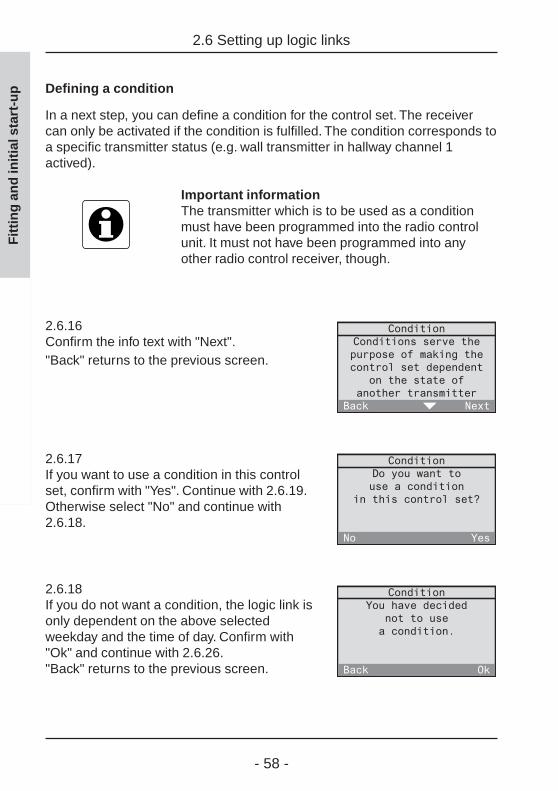
Defining a condition
In a next step, you can define a condition for the control set. The receivercan only be activated if the condition is fulfilled. The condition corresponds toa specific transmitter status (e.g. wall transmitter in hallway channel 1actived).
Important informationThe transmitter which is to be used as a conditionmust have been programmed into the radio controlunit. It must not have been programmed into anyother radio control receiver, though.
2.6.16Confirm the info text with "Next"."Back" returns to the previous screen.
2.6.17If you want to use a condition in this controlset, confirm with "Yes". Continue with 2.6.19.Otherwise select "No" and continue with2.6.18.
2.6.18If you do not want a condition, the logic link isonly dependent on the above selectedweekday and the time of day. Confirm with"Ok" and continue with 2.6.26."Back" returns to the previous screen.
2.6 Setting up logic links
Fit
tin
g a
nd
init
ial s
tart
-up

- 59 -
2.6 Setting up logic links
2.6.19If you want to use a condition, you must firstselect the radio control transmitter. Confirmthe info text with "Next".Important: A radio control detector and asmoke detector with radio control module isnot suitable for use as a condition.
2.6.20Select the room where the desired transmitteris located (in this case: hallway)."Back" returns to the previous screen.
2.6.21The following list contains only types oftransmitters already existing in the selectedroom. Select first a transmitter type (in thiscase: wall transmitter). Depending on theselected transmitter, observe also theinstructions on the following page."Back" returns to the previous screen.
2.6.22A list with the transmitters existing in thedesired room (in this case: wall transmitters)appears. Select the transmitter that is to serveas a condition."Back" returns to the previous screen.
2.6.23In the next step, select first the channel andthen the status of the transmitter.Confirm the info text with "Next"."Back" returns to the previous screen.
Fit
tin
g a
nd
init
ial s
tart
-up
- 60 -
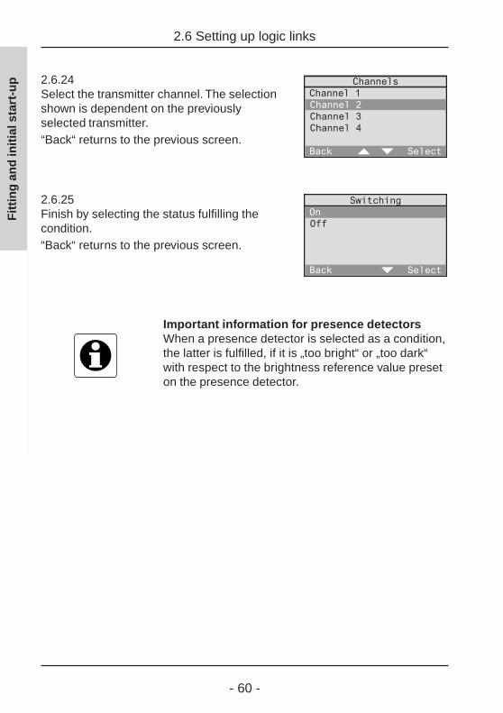
2.6.24Select the transmitter channel. The selectionshown is dependent on the previouslyselected transmitter.“Back“ returns to the previous screen.
2.6.25Finish by selecting the status fulfilling thecondition.“Back“ returns to the previous screen.
Important information for presence detectorsWhen a presence detector is selected as a condition,the latter is fulfilled, if it is „too bright“ or „too dark“with respect to the brightness reference value preseton the presence detector.
2.6 Setting up logic links
Fit
tin
g a
nd
init
ial s
tart
-up
- 61 -
2.6 Setting up logic links
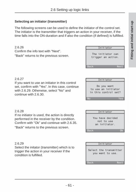
Selecting an initiator (transmitter)
The following screens can be used to define the initiator of the control set.The initiator is the transmitter that triggers an action in your receiver, if thetime falls into the ON-duration and if also the condition (if defined) is fulfilled.
2.6.26Confirm the info text with "Next"."Back" returns to the previous screen.
2.6.27If you want to use an initiator in this controlset, confirm with "Yes". In this case, continuewith 2.6.29. Otherwise, select "No" andcontinue with 2.6.30.
2.6.28If no initiator is used, the action is directlyperformed in the receiver by the condition.Confirm with "Ok" and continue with 2.6.35."Back" returns to the previous screen.
2.6.29Select the initator (transmitter) which is totrigger the action in your receiver if thecondition is fulfilled.
Fit
tin
g a
nd
init
ial s
tart
-up
- 62 -
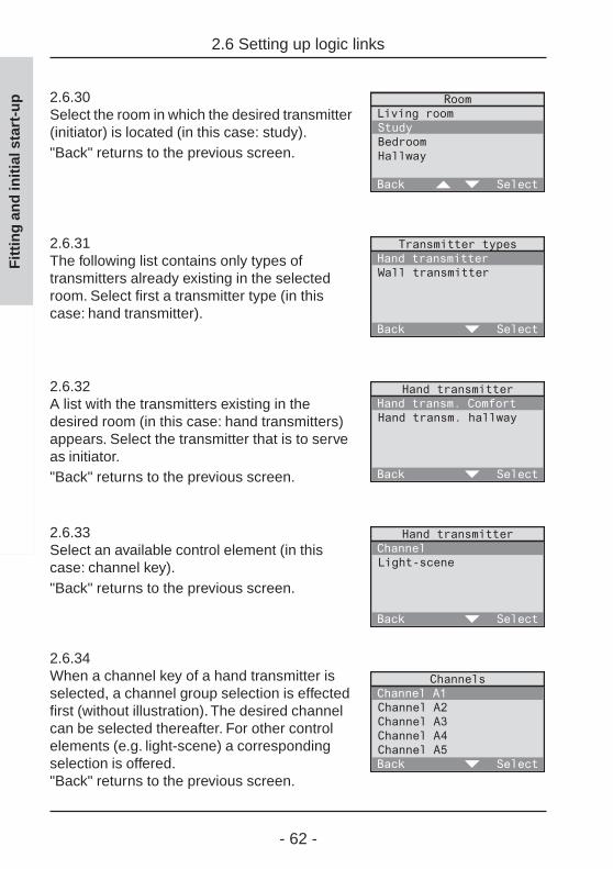
2.6.30Select the room in which the desired transmitter(initiator) is located (in this case: study)."Back" returns to the previous screen.
2.6.31The following list contains only types oftransmitters already existing in the selectedroom. Select first a transmitter type (in thiscase: hand transmitter).
2.6.32A list with the transmitters existing in thedesired room (in this case: hand transmitters)appears. Select the transmitter that is to serveas initiator."Back" returns to the previous screen.
2.6.33Select an available control element (in thiscase: channel key)."Back" returns to the previous screen.
2.6.34When a channel key of a hand transmitter isselected, a channel group selection is effectedfirst (without illustration). The desired channelcan be selected thereafter. For other controlelements (e.g. light-scene) a correspondingselection is offered."Back" returns to the previous screen.
2.6 Setting up logic links
Fit
tin
g a
nd
init
ial s
tart
-up
- 63 -
2.6 Setting up logic links
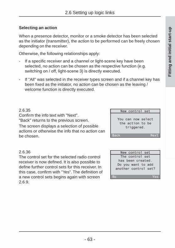
Selecting an action
When a presence detector, monitor or a smoke detector has been selectedas the initiator (transmitter), the action to be performed can be freely chosendepending on the receiver.
Otherwise, the following relationships apply:
- If a specific receiver and a channel or light-scene key have beenselected, no action can be chosen as the respective function (e.g.switching on / off, light-scene 3) is directly executed.
- If "All" was selected in the receiver types screen and if a channel key hasbeen fixed as the initiator, no action can be chosen as the leaving /welcome function is directly executed.
2.6.35Confirm the info text with "Next"."Back" returns to the previous screen.The screen displays a selection of possibleactions or otherwise the info that no action canbe chosen.
2.6.36The control set for the selected radio controlreceiver is now defined. It is also possible todefine further control sets for this receiver. Inthis case, confirm with "Yes". The definition ofa new control sets begins again with screen2.6.9.
Fit
tin
g a
nd
init
ial s
tart
-up

- 64 -
Changing logic linksTo edit or to delete an established logic link, readchapter 3.2.3 "Changing logic links".
If the start-up dialog "new logic link" was called up directly from the menu,pressing "No" takes you back to the menu.
If you are in the initial start-up, pressing "No" displays screen 2.6.36.
2.6.37To set up another logic link in the intial start-up, confirm now with "Yes". "No" terminatesthe initial start-up and takes you back to themenu.
2.6 Setting up logic links
Fit
tin
g a
nd
init
ial s
tart
-up

- 65 -
3.0 List of components
3.0 List of components
After initial start-up, a list of all programmed transmitters and receivers canbe displayed for each room under "Configuration - Components - Overview"in the menu.
This list offers the possibility of making individual changes:
3.1 Changing the name of a room
3.2 Changing transmitters and receivers
• Changing the name of a transmitter or receiver
• Assigning another room to transmitters or receivers
• Deleting a transmitter
• Deleting a receiver
3.3 Programming new transmitters or receivers for existing rooms
This menu moreover permits defining special functions for individualreceivers such as delay times and actions to be performed within the"Welcome" function:
3.4 Special functions
Fit
tin
g a
nd
init
ial s
tart
-up

- 66 -
3.1 Changing the name of a room
To change the name of a room, select "Configuration - Components –Overview" in the menu.
3.1.1A list of available rooms is displayed. Selectthe room whose name is to be changed (inthis case: study)."Back" returns to the previous screen.
3.1.2Select "Change name" in this menu."Back" returns to the previous screen.
3.1.3In this screen, the selected name can beedited or the new name entered.For entering text, use the keypad (see fold-outpage (3))."Abc" shifts between capital and small letters."<-" deletes the last character. When you haveentered a name, confirm with "Ok"."Back" returns to the previous screen.
3.1 Changing the name of a room
Fit
tin
g a
nd
init
ial s
tart
-up
- 67 -
3.2 Changing of transmitters and receivers
3.2 Changing of transmitters and receivers
The following changes can be made with respect to programmedtransmitters and receivers:
• Changing the name of a transmitter or receiver• Assigning another room to transmitters or receivers• Deleting a transmitter• Deleting a receiver
To make one of these changes, select first "Configuration - Components -Overview" in the menu. The example describes the selection of a transmitter forwhich a change is to be made. Receiver changes are made in the same way.
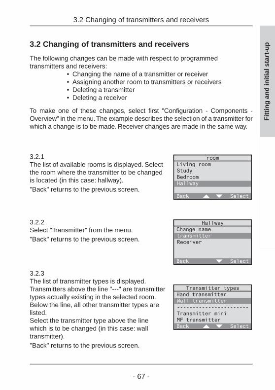
3.2.1The list of available rooms is displayed. Selectthe room where the transmitter to be changedis located (in this case: hallway)."Back" returns to the previous screen.
3.2.2Select "Transmitter" from the menu."Back" returns to the previous screen.
3.2.3The list of transmitter types is displayed.Transmitters above the line "---" are transmittertypes actually existing in the selected room.Below the line, all other transmitter types arelisted.Select the transmitter type above the linewhich is to be changed (in this case: walltransmitter)."Back" returns to the previous screen.
Fit
tin
g a
nd
init
ial s
tart
-up
- 68 -
3.2 Changing of transmitters and receivers
Fit
tin
g a
nd
init
ial s
tart
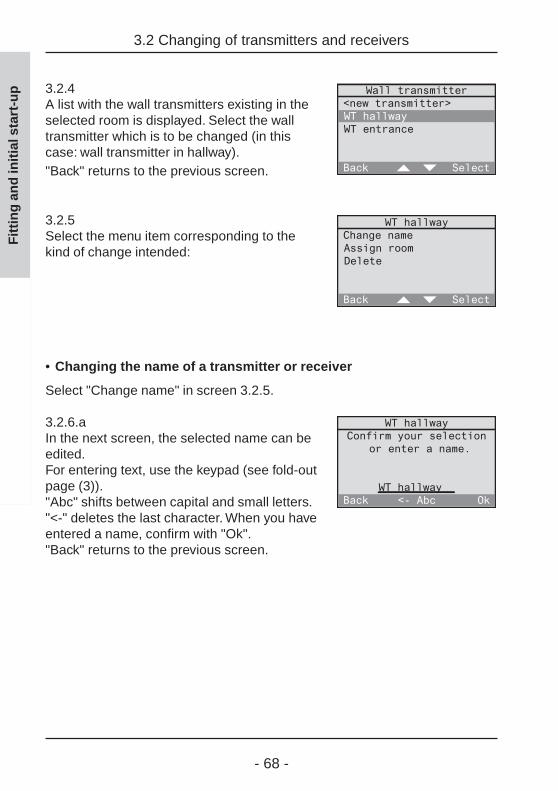
-up 3.2.4
A list with the wall transmitters existing in theselected room is displayed. Select the walltransmitter which is to be changed (in thiscase: wall transmitter in hallway)."Back" returns to the previous screen.
3.2.5Select the menu item corresponding to thekind of change intended:
• Changing the name of a transmitter or receiver
Select "Change name" in screen 3.2.5.
3.2.6.aIn the next screen, the selected name can beedited.For entering text, use the keypad (see fold-outpage (3))."Abc" shifts between capital and small letters."<-" deletes the last character. When you haveentered a name, confirm with "Ok"."Back" returns to the previous screen.

- 69 -
3.2 Changing of transmitters and receivers
• Assigning another room to transmitters or receivers
Select "Assign room" in screen 3.2.5.
3.2.6.bIn the following screen, you can then selectanother room for the transmitter."Back" returns to the previous screen.
• Deleting a transmitter
Select "Delete" in screen 3.2.5.
3.2.6.cTo definitely delete the selected transmitter,answer the confirmation request with "Yes".Otherwise select "No".
• Deleting a receiver
Select "Receiver" in screen 3.2.2 and "Delete" in screen 3.2.5.
3.2.6.dTo delete the selected receiver, answer theconfirmation request with "Yes". Otherwiseselect "No".
Fit
tin
g a
nd
init
ial s
tart
-up

- 70 -
3.2.6.eTo delete the link between the radio controlunit and the receiver completely, bring theradio control unit to within 5 m of your radiocontrol receiver and switch the receiver intoprogramming mode (cf. radio control receiveroperating instructions).Pressing "Next" deletes the receiver.
3.2.6.fCheck whether the radio control receiver hasconfirmed deletion (cf. radio control receiveroperating instructions). Without confirmation,press "No" to repeat the deleting procedurefrom step 3.2.6.e onwards.
3.2 Changing of transmitters and receivers
Fit
tin
g a
nd
init
ial s
tart
-up

- 71 -
3.3 Programming new transmitters or receivers in existing rooms
3.3 Programming new transmitters or receivers inexisting rooms
Besides programming of transmitters and receivers with the initial start-upassistant, fast programming of new radio control transmitters or receivers foralready existing rooms is also possible.
Start by selecting "Configuration - Components - Overview" from the menu.
3.3.1A list of available rooms is displayed. Selectthe room for which you want to program a newtransmitter or receiver (in this case: Hallway)."Back" returns to the previous screen.
3.3.2Select "Transmitter" or "Receiver" dependingon what you want to program. The followingdescription is an example for programming ofa new transmitter. The procedure for a receiveris the same."Back" returns to the previous screen.
3.3.3The list of transmitter types is displayed.Transmitters above the line "---" are transmittertypes actually existing in the selected room.Below the line, all other transmitter types arelisted.Select the new transmitter type above the linewhich is to be programmed (in this case: walltransmitter)."Back" returns to the previous screen.
Fit
tin
g a
nd
init
ial s
tart
-up
- 72 -
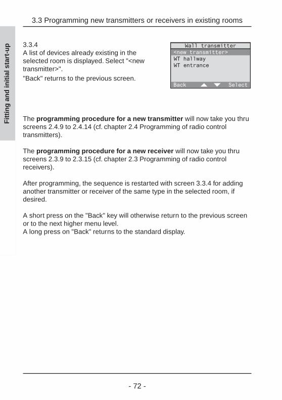
3.3.4A list of devices already existing in theselected room is displayed. Select "<newtransmitter>"."Back" returns to the previous screen.
The programming procedure for a new transmitter will now take you thruscreens 2.4.9 to 2.4.14 (cf. chapter 2.4 Programming of radio controltransmitters).
The programming procedure for a new receiver will now take you thruscreens 2.3.9 to 2.3.15 (cf. chapter 2.3 Programming of radio controlreceivers).
After programming, the sequence is restarted with screen 3.3.4 for addinganother transmitter or receiver of the same type in the selected room, ifdesired.
A short press on the "Back" key will otherwise return to the previous screenor to the next higher menu level.A long press on "Back" returns to the standard display.
3.3 Programming new transmitters or receivers in existing rooms
Fit
tin
g a
nd
init
ial s
tart
-up

- 73 -
3.4 Special functions (delay, action)
3.4 Special functions (delay, action)
If required, each radio control receiver can be programmed for the specialfunctions ‘delay’ and ‘action’. Three different settings are available:
Delay: 0 min; action: <none>
This is the preset configuration for each receiver, i.e. the respectivereceiver does not execute any special functions. When the returningfunction (‘welcome’ function) is called up, the value stored before leavingwill be restored.
Delay: 0 min; action: defined
On activation of the returning function, the respective receiver immediatelyexecutes the function defined here.
Example: switching actuator; delay: 0 min; action: on On activation of the returning function, the switching actuator switches on.
Delay: > 0 min; action: defined
On reception of a programmed radio telegram from the RADIO CONTROL UNIT, therespective receiver executes first the corresponding action. After thedefined delay, the receiver executes the action defined here under specialfunctions.
Example: switching actuator; delay: 1 min; action: offIn addition, a logic link is defined for this switching actuator, in which aradio control detector as initiator is to switch on the radio control receiver.
On reception of a detector telegram via the radio control unit, theswitching actuator is first switched on and then off again after 1 min.
On activation of the returning function, the value stored before leaving isrestored. After the delay of 1 min has elapsed, the actuator switches off.
Fit
tin
g a
nd
init
ial s
tart
-up
- 74 -
Technical information 1-channel flush-mountedswitching actuatorIf a 1-channel flush-mounted switching actuatorwhich is not at least version R2 is used in your radiocontrol system (see device rating plate), note thefollowing special behaviour:
On activation of the leaving function or on storing of alight-scene via the radio control unit, this switchingactuator always saves the "Off" status.In special function setting , this actuator would there-fore remain off on activation of the returning function.
If you prefer the "On" state instead, it is recommendedto select special function setting ‚ with
delay = 0 min; action: onThe switching actuator will then always switch onwhen the returning function is activated.
If light-scenes are stored with this actuator via theradio control unit, the device will always save the"Off" state. To save the "On" state for the light-scene,the scene must be stored with another radio controltransmitter (e.g. radio control hand transmitter).
Further reading
For more details please read also the two followingchapters of the operating instructions:
3.3 Working with light-scenes5.2 The returning / leaving function
3.4 Special functions (delay, action)
Fit
tin
g a
nd
init
ial s
tart
-up

- 75 -
3.4 Special functions (delay, action)
Setting of delays and actions for receivers
To set the delay time and the action for a specific receiver, select"Configuration - Components - Overview" from the menu.
3.4.1Select the room where the desired receiver islocated (in this case: Study)."Back" returns to the previous screen.
3.4.2Select "Receiver" in the menu."Back" returns to the previous screen.
3.4.3The list of receiver types is displayed.Receivers above the line "---" are receivertypes actually existing in the selected room.Below the line, all other receiver types arelisted.Select the receiver type above the line forwhich the delay and the action are to be set(in this case: Switching actuator)."Back" returns to the previous screen.
3.4.4A list with the switching actuators existing inthe selected room is displayed. Select theswitching actuator for which you want to setthe delay and the action (in this case: Desk)."Back" returns to the previous screen.
Fit
tin
g a
nd
init
ial s
tart
-up

- 76 -
3.4.5Select here "Special functions"."Back" returns to the previous screen.
3.4.6Select "Delay" to set a delay between 0 and240 min (interval 1 min).Select "Action" to program an action into thereceiver."Back" stores the adjusted values.
Actions: further reading
The meaning of individual actions is explained in thepresent fitting and start-up instructions in chapter 2.5"Setting up time-controlled programs" on page 47.
3.4 Special functions (delay, action)
Fit
tin
g a
nd
init
ial s
tart
-up

- 77 -
4.0 Repeater functions
4.0 Repeater functions
A repeater permits enlarging the transmitting and thus the working range ofa radio system.
Abb. 4.a: Function of a repeater
The repeater receives radio telegrams from radio control transmitters and retransmits these telegrams after a check with maximum power. The tele-gram is received and evaluated in a radio control receiver .
When a radio control unit is used in a radio control system, there are twopossible variants of realizing a repeater function:
4.1 Use of an external repeaterRead chapter 4.1, if you want to increase the working range ofyour radio system with an external repeater or if such a deviceis already in use.
4.2 Use of an internal repeaterRead chapter 4.2, if you want to improve the exchange of suchradio signals between a transmitter and a receiver that are inde-pendent of the control unit. In this case, the radio control unit itselfcan be used as repeater.
Fit
tin
g a
nd
init
ial s
tart
-up
- 78 -
4.1 Using an external repeater
An external repeater can be programmed into the radio control unit right fromthe beginning during the initial start-up procedure (cf. chapter 2.2). It is alsopossible to add an external repeater later to the radio control system.
To do so, select "Configuration - System - Repeater" in the menu. Confirmthe info screen with "Next".
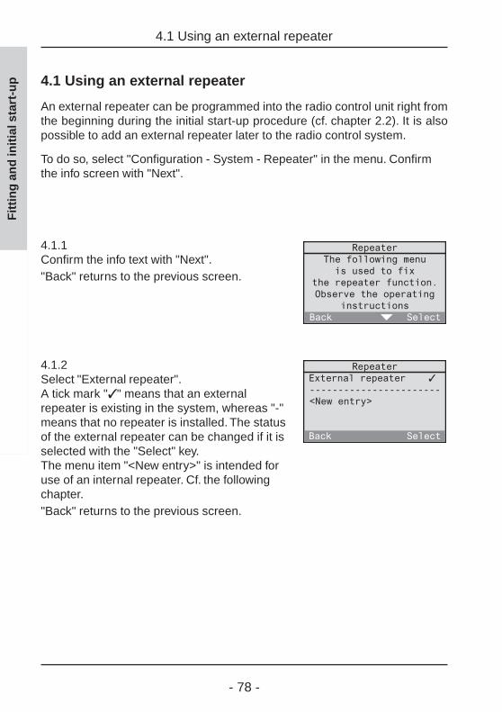
4.1.1Confirm the info text with "Next"."Back" returns to the previous screen.
4.1.2Select "External repeater".A tick mark "✓ " means that an externalrepeater is existing in the system, whereas "-"means that no repeater is installed. The statusof the external repeater can be changed if it isselected with the "Select" key.The menu item "<New entry>" is intended foruse of an internal repeater. Cf. the followingchapter."Back" returns to the previous screen.
4.1 Using an external repeater
Fit
tin
g a
nd
init
ial s
tart
-up

- 79 -
4.2 Using an internal repeater
4.2 Using an internal repeater
For radio communications between a transmitter and a receiver taking placeindependently of the radio control control unit, i.e. not used in logic links, theinternal repeater of the radio control unit itself can be used.
Abb. 4.b: Radio communication independentof the radio control unit
The internal repeater permits increasing the transmitting and thus theworking range of radio communication devices.
Abb. 4.c: Use of internal repeater
Important informationThe internal repeater can handle up to 30 different radiotransmitters.
Fit
tin
g a
nd
init
ial s
tart
-up
- 80 -
To use the radio control unit as a repeater, start by programming your radiotransmitter into the radio control unit. Cf. chapter 2.3 "Programming of radiocontrol transmitters".
Select then "Configuration - System - Repeater" in the menu. Confirm thefollowing info screen with "Next".
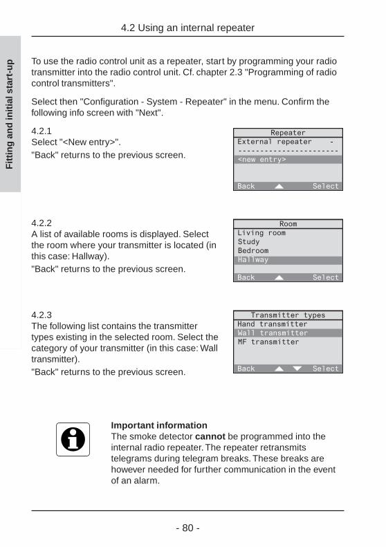
4.2.1Select "<New entry>"."Back" returns to the previous screen.
4.2.2A list of available rooms is displayed. Selectthe room where your transmitter is located (inthis case: Hallway)."Back" returns to the previous screen.
4.2.3The following list contains the transmittertypes existing in the selected room. Select thecategory of your transmitter (in this case: Walltransmitter)."Back" returns to the previous screen.
Important informationThe smoke detector cannot be programmed into theinternal radio repeater. The repeater retransmitstelegrams during telegram breaks. These breaks arehowever needed for further communication in the eventof an alarm.
4.2 Using an internal repeater
Fit
tin
g a
nd
init
ial s
tart
-up
- 81 -
4.2 Using an internal repeater
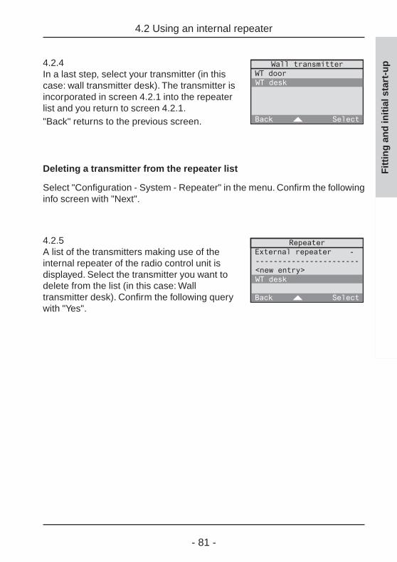
4.2.4In a last step, select your transmitter (in thiscase: wall transmitter desk). The transmitter isincorporated in screen 4.2.1 into the repeaterlist and you return to screen 4.2.1."Back" returns to the previous screen.
Deleting a transmitter from the repeater list
Select "Configuration - System - Repeater" in the menu. Confirm the followinginfo screen with "Next".
4.2.5A list of the transmitters making use of theinternal repeater of the radio control unit isdisplayed. Select the transmitter you want todelete from the list (in this case: Walltransmitter desk). Confirm the following querywith "Yes".
Fit
tin
g a
nd
init
ial s
tart
-up

- 82 -
5.0 Radio control unit utilization
The radio control unit is equipped with a dynamic memory which isoccupied by programmed transmitters and receivers, rooms, establishedprograms and logic links.
The memory utilization can be displayed by the radio control unit. Select"Configuration - System" from the menu.
5.0.1Select "Information" at the end of the systemmenu."Back" returns to the previous screen.
5.0.2The following screen displays the degree ofutilization of the radio control unit in percentand also the serial and version numbers (cf."Annex B – Serial and version numbers").
Utilization – example 1:
- 5 rooms: bedroom, living room, kitchen, hallway and bathroom- 20 radio transmitters and 20 radio receivers are in use- 5 programs with altogether 25 switching times are existing- 26 logic links with altogether 60 control sets are are existing
Degree of radio control unit utilization = approx. 12 %
5.0 Radio control unit
Fit
tin
g a
nd
init
ial s
tart
-up

- 83 -
5.0 Radio control unit
Fit
tin
g a
nd
init
ial s
tart
-upUtilization – example 2:
- 6 rooms: bedroom, children’s room, living room, kitchen, hallway andbathroom
- 60 radio transmitters and 90 radio receivers are in use- 18 programs with altogether 120 switching times are existing- 60 logic links with altogether 600 control sets are are existing
Degree of radio control unit utilization = approx. 70 %
Maximum limits
Besides the degree of utilization in percent, the following maximum limitsmust be observed for programming of the radio control unit:
- Receivers: max. 60 light actuators (switching or dimming actuators)max. 60 shutter actuators
- Transmitters: max. 60 radio transmitters per type and per room(transmitter types: hand transmitter, hand transmitterMini, wall transmitter, multifunction sensor, universaltransmitter, detector, presence detector, smoke detector)
- Rooms: max. 60 rooms
- Programs: max. 60 programsper program, 60 switching times max. can be used.
- Logic links: max. 60 logic linksper logic link, 60 control sets max. can be used.

- 84 -

- 85 -
Manual
Operating instructions(for the customer)

- 86 -
Table of contents
Operating instructions
1.0 Introduction ................................................................................. 88
1.1 Controls and connections ..................................................... 89
1.2 The standard screen ............................................................. 91
1.3 Directions for use .................................................................. 94
1.3.1 The function keys ......................................................... 94
1.3.2 The menu functions ...................................................... 95
1.3.3 Entering text ................................................................. 96
1.4 Component list ...................................................................... 97
2.0 Configuration .............................................................................. 98
2.1 Basic settings ........................................................................ 99
2.2 Setting the time ..................................................................... 101
2.3 Setting the shutter moving time ............................................. 102
2.4 Configuration menu access lock ........................................... 103
3.0 Automatic mode .......................................................................... 104
3.1 Working with programs ......................................................... 105
3.1.1 Setting up time-controlled programs ............................ 106
3.1.2 Activating and deactivating programs .......................... 119
3.1.3 Changing of programs .................................................. 120
3.1.4 Deleting programs ........................................................ 137
3.1.5 Simulation of presence ................................................. 138
Operating instructions - Table of contents
Op
erat
ing
inst
ruct
ion
s

- 87 -
3.2 Working with logic links ......................................................... 141
3.2.1 Setting up logic links .................................................... 143
3.2.2 Activating and deactivating logic links .......................... 154
3.2.3 Changing logic links ..................................................... 155
3.2.4 Deleting logic links ....................................................... 164
3.3 Working with light-scenes ..................................................... 165
3.3.1 Storing and changing light-scenes ............................... 167
3.3.2 Recalling light-scenes .................................................. 170
4.0 Manual operation ........................................................................ 172
5.0 Extra functions ............................................................................ 177
5.1 Using short messages .......................................................... 177
5.2 The returning (welcome) / leaving function ........................... 180
5.3 The Master key ..................................................................... 182
5.4 Special functions (delay, action) ............................................. 183
6.0 Project saving ............................................................................... 187
6.1 Saving the project ................................................................. 188
6.2 Loading the project ................................................................ 189
7.0 Transmitter diagnosis ................................................................. 190
Operating instructions - Table of contents
Op
erat
ing
inst
ruct
ion
s

- 88 -
Op
erat
ing
inst
ruct
ion
s
1.0 Introduction
Your electrical fitter has installed your RADIO CONTROL UNIT and and put intooperation for you. He has moreover performed the first software settings(e.g. by storing time-controlled programs).
The present operating instructions inform you about the designated use of aradio control unit and make you familiar with all its functions.
For more detailed information, fold out the front cover page. This pagecontains illustrations of all controls and connections and of the standarddisplay screen of your radio control unit. A detailed description is given inchapters 1.1 and 1.2.
Safety warnings
Attention!The unit must be repaired only by qualifiedelectricians.
1.0 Introduction
Op
erat
ing
inst
ruct
ion
s

- 89 -
Op
erat
ing
inst
ruct
ion
s
1.1 Controls and connections
(1) Display (7 lines of 20 characters each)The display screen displays all data and menu entries.The display can moreover be used to write, save and edit shortmessages.
(2) 4 function keys (soft-keys)The function keys control the menu operations. The respective functionof the key is indicated in the bottom line of the display.
(3) 12-key keypadThe keypad can be used to enter letters, numbers and special characters.
(4) Chip-card readerThe chip-cards supplied with the device can be used to save and toreload the actual settings. Chip-cards can also be used to expand andto update the software.
(5) Mains connectionThe radio control unit is supplied with power via a mains connecting cordor a 230 V installation line.
(6) Interface (Western socket)In future software versions, this interface can be used for dataexchange with other devices.
1.1 Controls and connections
Op
erat
ing
inst
ruct
ion
s

- 90 -
Op
erat
ing
inst
ruct
ion
s
(7) Digital inputThis input can be used in future software versions to enlarge thefunctionality.
(8) Temperature sensorThe standard screen displays the current room temperature. Thistemperature is measured by the temperature sensor and is dependenton the fitting location. A temperature correction permits adaptation tothe current room temperature (cf. chapter 2.1 "Basic settings").
(9) Master keyThe master key can be used to call up and edit short messages or toactivate the leave / welcome function. Please read also chapter 5.0"Extra functions".
1.1 Controls and connections
Op
erat
ing
inst
ruct
ion
s

- 91 -
Op
erat
ing
inst
ruct
ion
s
1.2 The standard screen
In everdyay use, your screen shows the standard display (see fold-out page),where you can call up further functions. When the menu is displayed and whenno key is pressed within ca. 1 minute, the screen goes back to the standarddisplay.The standard screen displays the following information:
(10) Time of dayThe actual time is displayed in the 24h or 12h format. In Germany, thetime can also be controlled by the DCF77 radio time signal.
(11) WeekdayDisplays the actual day of the week.
(12) DCF77 field strength indicatorWhen setting the time, the number displayed represents the fieldstrength of the received DCF77 signal.The field strength indicator shows the DCF77 signal quality in the formof a number between ‘1’ and ‘5’. With a ‘0’ and a ‘1’, reception is nearlyimpossible. With a ‘2’, ‘3’, ‘4’ or ‘5’, reception is possible with a higherfigure corresponding to better reception. When the clock issynchronized on the time signal, the number disappears.
(13) DCF77 receive indicatorThe antenna symbol show the status of the DCF77 time signal. Threedifferent states can be indicated:
symbol on: DCF77 time signal being received
symbol flashing: DCF77 time signal synchronizing or signal receptiondisturbed
no symbol: Clock actually not controlled by DCF77 time signal.
1.2 The standard screen
Op
erat
ing
inst
ruct
ion
s

- 92 -
(14) Key lockTo prevent unauthorized use of the radio control unit, the keypad canbe locked. To lock and unlock the key-pad, depress the key in thestandard display for ca. 1 s. The key lock function concerns only on thekeys of the standard display.
(15) Short message symbolThe reception of a short message is signalled by the letter envelopesymbol. In the absence of short messages, this symbol is not displayed.The short message can be called up from the menu or with the masterkey (9) of the radio control unit. Read also chapter 5.0 "Extra functions".
(16) Presence / absence symbolThis symbol signals the state of your radio control unit.
present
absent
The respective welcome / leave function with which you can changebetween the ‘present’ and ‘absent’ modes, is described in chapter 5.2"The welcome / leave function" of the operating instructions.
(17) Menu line function keysThe 4 function keys control different functions which depend on themenu line. The functions are displayed in the dark bottom line line.
(18) Temperature displayThe actual room temperature is indicated in "Degrees Celsius" or"Degrees Fahrenheit".
Op
erat
ing
inst
ruct
ion
s
1.2 The standard screen
Op
erat
ing
inst
ruct
ion
s

- 93 -
Op
erat
ing
inst
ruct
ion
s
(19) Transmit / receive indicatorWhen the radio control unit sends or receives telegrams, this isindicated by the letters
T (transmit)R (receive)
Receive indicator R indicates reception of every telegram irrespectiveof this telegram having been programmed beforehand or not.
(20) Power supplyWhen the 230 V supply is o.k., no plug sysmbol is visible. If the powersupply is disturbed or interrupted, the plug symbol flashes.
(21) Battery displayThe battery symbol signals the status of the batteries inserted withthree different displays:
No symbol: The batteries are in good condition.
Symbol on: In the event of power failure, the batteries canensure an emergency operation of less than 6 hours.
Symbol flashing: The batteries must be replaced. In addition to thewarning tone sounding every minute, the standardscreen displays the message "Please insert newbatteries". The message must be confirmed with "Ok".
HourglassIf the hourglass symbol appears in the upper right-hand corner of the display,the radio control unit is busy and does not accept commands. Radiotelegrams received during this time will be processed after the hourglasshas disappeared.
Display settingsTo configure the display screen, read chapter 2.0"Settings" of the present operating instructions.
1.2 The standard screen
Op
erat
ing
inst
ruct
ion
s

- 94 -
Op
erat
ing
inst
ruct
ion
s
1.3 Directions for use
Op
erat
ing
inst
ruct
ion
s
1.3 Directions for use
1.3.1 The function keys
The 4 function keys (2) are the central control elements of the radio controlunit. The function of these keys depends on the text in the function key menuline (17). The function keys can all be assigned to the same function or todifferent functions.
In fig. 1.a, all 4 keys have the same function: pressing any of these keys willin this case display the main menu.
Fig. 1.a: Function of the function keys

- 95 -
Op
erat
ing
inst
ruct
ion
s
1.3.2 The menu functions
Your radio control unit offers a number of functions and settings with which itcan be optimally adapted to your requirements.
These functions are contained in menus and submenus which can beaccessed with the function keys.
Access to a menu function
- In the standard display, press any of the 4function keys (Fig. 1.b) to get into the mainmenu.
- In the menu, the bar can be moved withfunction keys 2 and 3 up (=) and down (> ).To activate a menu item highlighted by thegrey bar, press function key 4 "Select" todisplay the corresponding submenu of theradio control unit.
Quick selection of a menu item is alsopossible with the number keys of the keypad.Just press the number key corresponding tothe position of the menu item (in this case: 3for automatic). Menu items in position 10 orhigher in the menu list cannot be activatedwith the quick-select option.
Quitting the menu functions
To quit a submenu and get back to the next higher level, press briefly fuctionkey 1 "Back". A long press on function key 1 "Back" takes you back to thestandard display.
1.3.2 The menu functions
Op
erat
ing
inst
ruct
ion
s
Fig. 1.c: Menu

- 96 -
Op
erat
ing
inst
ruct
ion
s
1.3.3 Entering text
Op
erat
ing
inst
ruct
ion
s
1.3.3 Entering text
In some functions, the entry of text is possible. This concerns, for instance,the writing of short messages. Entering is done in the same way as with amobile phone by pressing a key once or several times for each character.
Please note that not all of the charactersavailable are printed on the keys. Fig. 1.d isa list of all available characters
Examples:
- To type an "a" press key (2) once.
- To type an "e" press key (3) quickly twotimes.
- To type an "s" press key (7) quickly fourtimes.
- To insert a blank, press key (1) once.
To type a character using the same key as for the previous character, waitca. 1 second before entering the new character.
Fig. 1.d: Character assignment

- 97 -
Op
erat
ing
inst
ruct
ion
s
For entering text, the function keys always have the same function. They canbe used for text editing purposes:
- To change between capital letters (Abc)and small letters (abc) use function key 3.
- Function key 2 "<-" can be used todelete the character last typed. To deletemore than one character, keep this keypressed.
1.4 Component list
All radio control components (receivers and transmitters) programmed intothe radio control unit are stored in the radio control unit as shown in thediagram (Fig. 1.f).
This list simplifies in many cases the search for and the retrieval of radiocontrol components.
Examples: Hallway - Transmitters - Wall transmitters - WT doorKitchen - Receivers - Dimming actuators - DA dining table
1.4 Component list
Op
erat
ing
inst
ruct
ion
s
Fig. 1.e: Entering text
Fig. 1.f: Component list

- 98 -
Op
erat
ing
inst
ruct
ion
s
2.0 Configuration
Op
erat
ing
inst
ruct
ion
s
2.0 Configuration
To make the use of the radio control unit as agreable as possible for you, itis recommended to make some adjustments beforehand:
2.1 Basic settings
2.2 Setting the time
2.3 Setting the shutter moving time
2.4 Configuration menu access lock
For adjustment, select the system menu from the main menu "Configuration- System" (see fig. 2.a).
Fig. 2.a: The system menu

- 99 -
Op
erat
ing
inst
ruct
ion
s
2.1 Basic settings
In the system menu ("Configuration - System") the following basic settings ofyour radio control unit can be made:
Lighting
always on: The display lighting is always on.always off: The display lighting is always off.automatic: After each key press, the display lighting is on for ca. 60 s.
To save batteries, the lighting is always off during battery operation.
Contrast
This setting adjusts the display contrast in steps from 1 to 7. Step 1corresponds to a low contrast whereas step 7 gives high contrast.
The contrast can moreover be set by pressing the key simultaneouslywith function key 2 for higher and with function key 3 for lower contrast.
2.1 Basic settings
Op
erat
ing
inst
ruct
ion
s
Fig. 2.b: Function keys 2 & 3
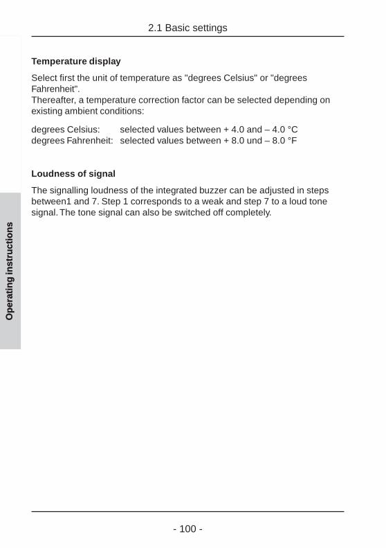
- 100 -
Op
erat
ing
inst
ruct
ion
s
2.1 Basic settings
Op
erat
ing
inst
ruct
ion
s
Temperature display
Select first the unit of temperature as "degrees Celsius" or "degreesFahrenheit".Thereafter, a temperature correction factor can be selected depending onexisting ambient conditions:
degrees Celsius: selected values between + 4.0 and – 4.0 °Cdegrees Fahrenheit: selected values between + 8.0 und – 8.0 °F
Loudness of signal
The signalling loudness of the integrated buzzer can be adjusted in stepsbetween1 and 7. Step 1 corresponds to a weak and step 7 to a loud tonesignal. The tone signal can also be switched off completely.
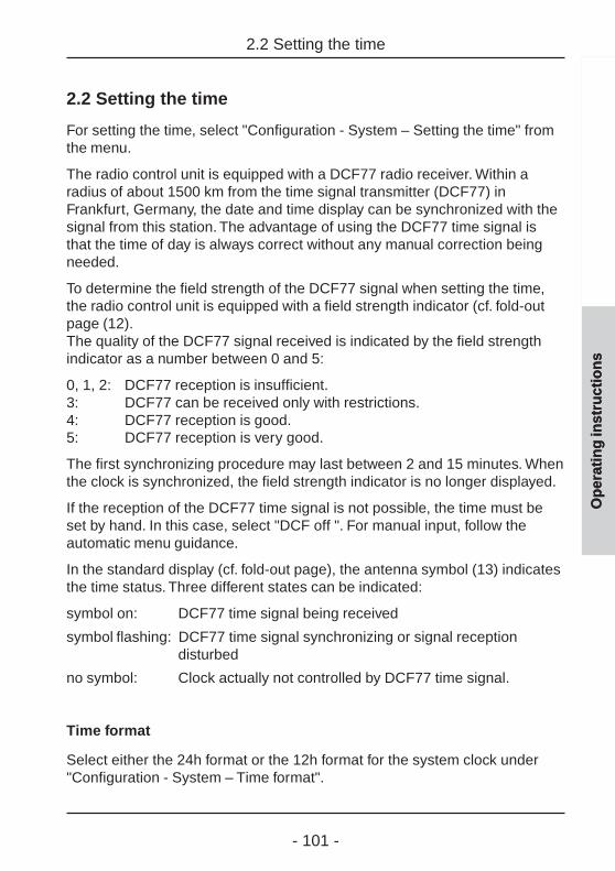
- 101 -
Op
erat
ing
inst
ruct
ion
s
2.2 Setting the time
For setting the time, select "Configuration - System – Setting the time" fromthe menu.
The radio control unit is equipped with a DCF77 radio receiver. Within aradius of about 1500 km from the time signal transmitter (DCF77) inFrankfurt, Germany, the date and time display can be synchronized with thesignal from this station. The advantage of using the DCF77 time signal isthat the time of day is always correct without any manual correction beingneeded.
To determine the field strength of the DCF77 signal when setting the time,the radio control unit is equipped with a field strength indicator (cf. fold-outpage (12).The quality of the DCF77 signal received is indicated by the field strengthindicator as a number between 0 and 5:
0, 1, 2: DCF77 reception is insufficient.3: DCF77 can be received only with restrictions.4: DCF77 reception is good.5: DCF77 reception is very good.
The first synchronizing procedure may last between 2 and 15 minutes. Whenthe clock is synchronized, the field strength indicator is no longer displayed.
If the reception of the DCF77 time signal is not possible, the time must beset by hand. In this case, select "DCF off ". For manual input, follow theautomatic menu guidance.
In the standard display (cf. fold-out page), the antenna symbol (13) indicatesthe time status. Three different states can be indicated:
symbol on: DCF77 time signal being received
symbol flashing: DCF77 time signal synchronizing or signal receptiondisturbed
no symbol: Clock actually not controlled by DCF77 time signal.
Time format
Select either the 24h format or the 12h format for the system clock under"Configuration - System – Time format".
2.2 Setting the time
Op
erat
ing
inst
ruct
ion
s

- 102 -
Op
erat
ing
inst
ruct
ion
s
2.3 Setting the shutter moving time
Op
erat
ing
inst
ruct
ion
s
2.3 Setting the shutter moving time
For shutters with identical moving times, the radio control unit offers the possi-bility of moving the shutter into predefined shutter positions between 0 %(uppermost position) and 100 % (lowermost position) (Fig. 2.c). Theseshutter positions can be used for actions in programs or in logic links. Formore information, read the corresponding chapters.
Fig. 2.c: Shutter position
Measure first the moving time of the concerned shutter from the highest tothe lowest point using a stop timer. Enter the time in seconds in the menuunder "Configuration - System – Shutter moving time" (Fig. 2.d). Shuttermoving times between 10 s and 120 s can be set.
Fig. 2.d: Setting the shutter moving time
This shutter moving time is the basis for movement into all of the selectedpositions.
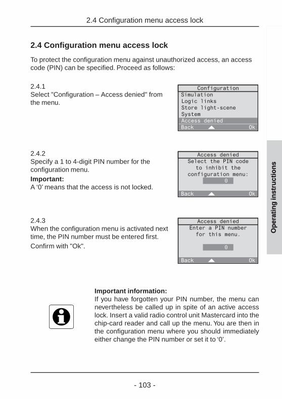
- 103 -
Op
erat
ing
inst
ruct
ion
s
2.4 Configuration menu access lock
To protect the configuration menu against unauthorized access, an accesscode (PIN) can be specified. Proceed as follows:
2.4.1Select "Configuration – Access denied" fromthe menu.
2.4.2Specify a 1 to 4-digit PIN number for theconfiguration menu.Important:A ‘0’ means that the access is not locked.
2.4.3When the configuration menu is activated nexttime, the PIN number must be entered first.Confirm with "Ok".
Important information:If you have forgotten your PIN number, the menu cannevertheless be called up in spite of an active accesslock. Insert a valid radio control unit Mastercard into thechip-card reader and call up the menu. You are then inthe configuration menu where you should immediatelyeither change the PIN number or set it to ‘0’.
2.4 Configuration menu access lock
Op
erat
ing
inst
ruct
ion
s
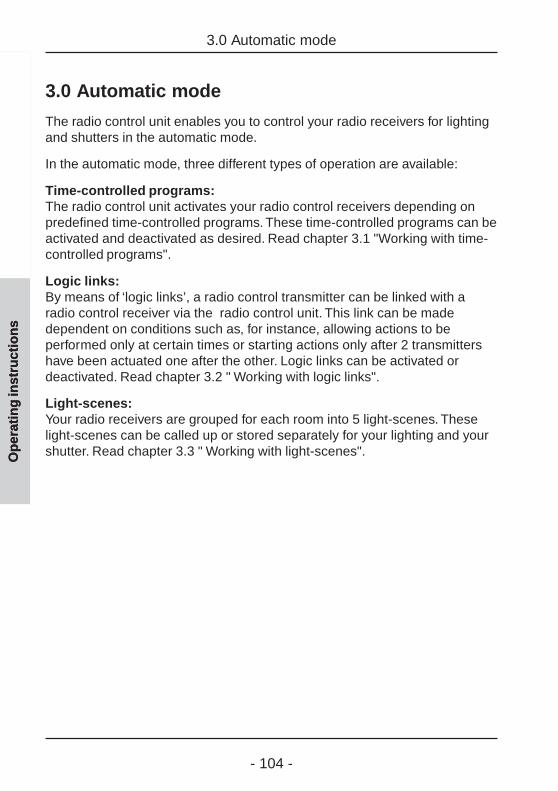
- 104 -
Op
erat
ing
inst
ruct
ion
s
3.0 Automatic mode
Op
erat
ing
inst
ruct
ion
s
3.0 Automatic mode
The radio control unit enables you to control your radio receivers for lightingand shutters in the automatic mode.
In the automatic mode, three different types of operation are available:
Time-controlled programs:The radio control unit activates your radio control receivers depending onpredefined time-controlled programs. These time-controlled programs can beactivated and deactivated as desired. Read chapter 3.1 "Working with time-controlled programs".
Logic links:By means of ‘logic links’, a radio control transmitter can be linked with aradio control receiver via the radio control unit. This link can be madedependent on conditions such as, for instance, allowing actions to beperformed only at certain times or starting actions only after 2 transmittershave been actuated one after the other. Logic links can be activated ordeactivated. Read chapter 3.2 " Working with logic links".
Light-scenes:Your radio receivers are grouped for each room into 5 light-scenes. Theselight-scenes can be called up or stored separately for your lighting and yourshutter. Read chapter 3.3 " Working with light-scenes".

- 105 -
Op
erat
ing
inst
ruct
ion
s
3.1 Working with programs
A program can control your lighting and your shutters automaticallydepending on the time of day. You can, for instance set up and activate aprogram which simulates presence during your holidays.
The following chapters explain how to- set up (chapter 3.1.1)- activate (chapter 3.1.2)- deactivate (chapter 3.1.2)- modify (chapter 3.1.3)- delete (chapter 3.1.4)
time-controlled programs.
You will also learn how to use a time-controlled program for the simulation ofpresence (chapter 3.1.5).
3.1 Working with programs
Op
erat
ing
inst
ruct
ion
s

- 106 -
3.1.1 Setting up time-controlled programs
Your electrical fitter may already have installed some initial time-controlledprograms in your radio control unit. You can, however, add further programsin accordance with your personal needs.
This is done with the help of the initial start-up dialog "new program" whichcan be called up in the main menu under "Configuration – Programs – <Newprogram>".
To set up time-controlled programs, follow the dialog instructions on thedisplay of your radio control unit.
3.1.1 Setting up time-controlled programs
Fig.. 3.a: Program entry sequence
Op
erat
ing
inst
ruct
ion
s

- 107 -
Op
erat
ing
inst
ruct
ion
s
3.1.1 Setting up time-controlled programs
Astro time
The switching times stored in your programs can – if necessary – beautomatically adapted to the astro time (sunset and/or sunrise times duringthe year). A distinction is made between switching times for blinds/shuttersand lighting.
WZ:Central European winter timeSZ: Central European summer
time (winter + 1 h)
Fig. 2.c:Astro switching times over theyear (approx. location: Würzburg)
When the astro function is active, the switching times will be shifted as follows:
Blind/shutter:
Switching times in the morning falling into darkness will be executed at thetime of sunrise (astro morning curve).
Switching times in the evening falling into darkness will be executed at thetime of sunset (astro evening curve).

- 108 -
Op
erat
ing
inst
ruct
ion
s
3.1.1 Setting up time-controlled programs
Example for blinds/shutters:
MON - SUN: 06:30 h shutter raisedMON - SUN: 19:10 h shutter lowered
The shutter is raised in the morning at sunset – but not before 6:30 h – andis lowered in the evening at sunset – but not later than 19:10 h..
Lighting:
Switching times in the morning falling into daylight are executed already atthe time of sunrise (astro morning curve).
Switching times in the evening falling into daylight are executed only at thetime of sunset (astro evening curve).
Example for lighting:
MON - SUN: 09:00 h lights switched offMON - SUN: 16:15 h lights switched on
Both times fall into daylight during the whole year; this means that not theswitching times indicated, but rather the astro times will be executed.
Important information:Switching times valid for blinds/shutters and also forlighting (type: all) will be handled in the astro mode asshutter switching times.
Fig. 3.c:Astro function example forshutter moving actions
- 109 -
Op
erat
ing
inst
ruct
ion
s
3.1.1 Setting up time-controlled programs
Astro time-shift
The astro time-shift permits adapting the factory-adjusted surise and sunsettimes (cf. fig. 3.b) to individual local conditions. The maximum shift of ± 120 minis performed for all days of the year.
Example 1:
The veranda is located at the southwest side of the house. Since the sun sets inthe west, it will get dark there a little later. The astro time for sunset can thereforebe shifted slightly forwards (e.g. + 0:50 shutter lowered 50 min later)
Example 2:
On a slope at the east side of the house it will get dark earlier than fixed by theastro curve. The astro time for sunset can therefore be shift slightly backwards(e.g. - 0:20 shuuter lowered 20 min earlier).

- 110 -
3.1.1 Setting up time-controlled programs
Op
erat
ing
inst
ruct
ion
s
Procedure for setting up time-controlled programs
3.1.1.1Confirm the info text for setting up a newprogram with "Next"."Abort" returns to the main menu.
3.1.1.2At first, the program must be given a name.Confirm the info text "Next"."Abort" returns to the main menu.
3.1.1.3Select a new name for the program from thelist or select <New name> to define a newprogram name.Confirm your selection with "Select"."Back" returns to the previous screen.
3.1.1.4In this screen, the selected room name can beedited or the new room name entered. Thename may consist of up to 16 characters.For entering text, use the keypad (see fold-outpage (3))."Abc" shifts between capital and small letters."<-" deletes the last character.When you have entered a room name, confirmwith "Ok"."Back" returns to the previous screen.
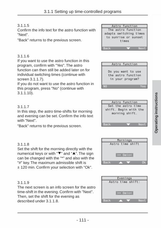
- 111 -
Op
erat
ing
inst
ruct
ion
s
3.1.1 Setting up time-controlled programs
3.1.1.5Confirm the info text for the astro function with"Next"."Back" returns to the previous screen.
3.1.1.6If you want to use the astro function in thisprogram, confirm with "Yes". The astrofunction can then still be added later on forindividual switching times (continue withscreen 3.1.1.7).If you do not want to use the astro function inthis program, press "No" (continue with3.1.1.10).
3.1.1.7In this step, the astro time-shifts for morningand evening can be set. Confirm the info textwith "Next"."Back" returns to the previous screen.
3.1.1.8Set the shift for the morning directly with thenumerical keys or with ">" and "=". The signcan be changed with the "*" and also with the"#" key. The maximum admissible shift is± 120 min. Confirm your selection with "Ok".
3.1.1.9The next screen is an info screen for the astrotime-shift in the evening. Confirm with "Next".Then, set the shift for the evening asdescribed under 3.1.1.8.

- 112 -
3.1.1 Setting up time-controlled programs
Op
erat
ing
inst
ruct
ion
s
3.1.1.10In the next step, you can fix the weekdays onwhich the desired action is to be performed.The action (e.g. activating the switchingactuator or raising the shutter) is determinedat the end of this dialog.Confirm the info text with "Next"."Back" returns to the previous screen.
3.1.1.11Select now a predefined weekday combination(in this case: Mo to Fr). The selection can stillbe changed in the following screen. If youwant to define the days freely, select "Other".Confirm your selection with "Select"."Back" returns to the previous screen.
3.1.1.12This screen displays the weekdaycombination. Selected days are shownunderlined (in this case: Mo to Fr). If you wantto change this combination, you can move thecursor in the weekday display with "<-" and"->" and add or remove a day to or from theweekday combination with "Select".If the underlinded days correspond to thedesired combination, place the cursor on "Ok"and confirm with "Select".
3.1.1.13In the next step, you can fix the time of day atwhich the action is to be performed. Confirmthe info text with "Next"."Back" returns to the previous screen.
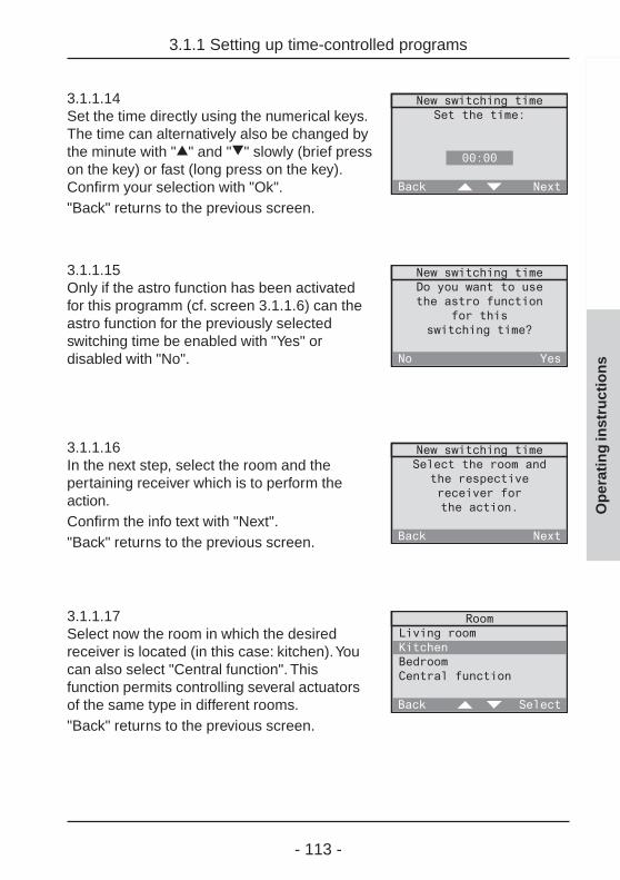
- 113 -
3.1.1 Setting up time-controlled programs
Op
erat
ing
inst
ruct
ion
s
3.1.1.14Set the time directly using the numerical keys.The time can alternatively also be changed bythe minute with "=" and ">" slowly (brief presson the key) or fast (long press on the key).Confirm your selection with "Ok"."Back" returns to the previous screen.
3.1.1.15Only if the astro function has been activatedfor this programm (cf. screen 3.1.1.6) can theastro function for the previously selectedswitching time be enabled with "Yes" ordisabled with "No".
3.1.1.16In the next step, select the room and thepertaining receiver which is to perform theaction.Confirm the info text with "Next"."Back" returns to the previous screen.
3.1.1.17Select now the room in which the desiredreceiver is located (in this case: kitchen). Youcan also select "Central function". Thisfunction permits controlling several actuatorsof the same type in different rooms."Back" returns to the previous screen.
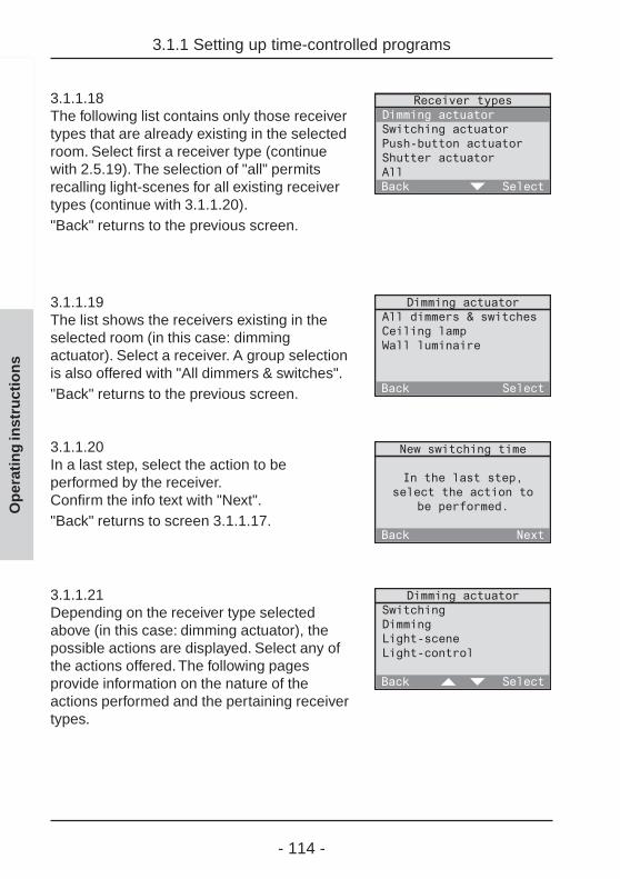
- 114 -
3.1.1 Setting up time-controlled programs
Op
erat
ing
inst
ruct
ion
s
3.1.1.18The following list contains only those receivertypes that are already existing in the selectedroom. Select first a receiver type (continuewith 2.5.19). The selection of "all" permitsrecalling light-scenes for all existing receivertypes (continue with 3.1.1.20)."Back" returns to the previous screen.
3.1.1.19The list shows the receivers existing in theselected room (in this case: dimmingactuator). Select a receiver. A group selectionis also offered with "All dimmers & switches"."Back" returns to the previous screen.
3.1.1.20In a last step, select the action to beperformed by the receiver.Confirm the info text with "Next"."Back" returns to screen 3.1.1.17.
3.1.1.21Depending on the receiver type selectedabove (in this case: dimming actuator), thepossible actions are displayed. Select any ofthe actions offered. The following pagesprovide information on the nature of theactions performed and the pertaining receivertypes.

- 115 -
3.1.1 Setting up time-controlled programs
Op
erat
ing
inst
ruct
ion
s
Description of performed actions
Important information:If you program also a special function for the receiver,it is possible that after performing the action described,the receiver will moreover perfom a special function.Read also chapter 5.4 "Special functions".
Switching (only with: switching and dimming actuators)
On / OffThe selected receiver is switched on and off.
Dimming (only with: dimming actuators)
Dimming levelThe dimming actuator can be dimmed to acertain brightness level. Adjust the brightnesslevel directly with the numerical keys or with"=" and ">".When "Ok" is pressed for the first time, thebrightness level is set in the assigned receiverfor visual checking.When "Ok" is pressed a second time, thebrightness level is definitely stored and thescreen terminated."Back" returns to the previous screen.

- 116 -
3.1.1 Setting up time-controlled programs
Op
erat
ing
inst
ruct
ion
s
Momentary contact function (only with: push-button actuators)
ActuateA press on the selected push-button actuator transmits a single pulse.
Light-scene (only with: switching, dimming, shutter actuators and All)
Light-scene 1-5The lamps are set to the value of the recalled light-scene. With shutters,only one of the two limit positions can be stored in a light-scene.
All-ON / All-OFFThe All-ON resp. the All-OFF function is executed in the selected receiver.
Shutter (only with: shutter actuators)
Limit position – top / bottomThe selected shutter is moved to the upper or lower position.
Shutter movementThe selected shutter can be moved into aspecific position, if the shutter moving timehas been defined beforehand. Read also2.3 "Setting the shutter moving time" in theoperating instructions. 0 % corresponds to"completely up" and 100 % corresponds to"completely down". Adjust the shutterposition directly with the help of thenumerical keys or with "=" and ">".After the first confirmation with "Ok", the position is approached for visualchecking. After the second confirmation with "Ok", the position is definitelystored and the screen terminated. "Back" returns to the previous screen.
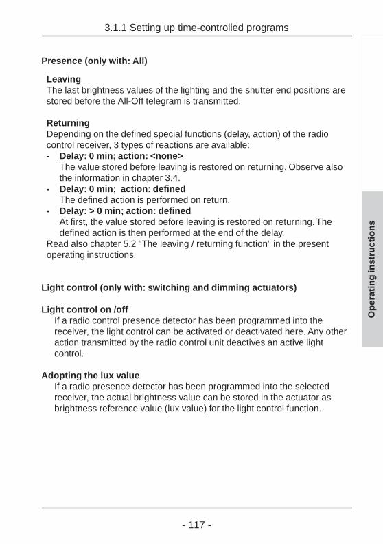
- 117 -
3.1.1 Setting up time-controlled programs
Op
erat
ing
inst
ruct
ion
s
Presence (only with: All)
LeavingThe last brightness values of the lighting and the shutter end positions arestored before the All-Off telegram is transmitted.
ReturningDepending on the defined special functions (delay, action) of the radiocontrol receiver, 3 types of reactions are available:- Delay: 0 min; action: <none>
The value stored before leaving is restored on returning. Observe alsothe information in chapter 3.4.
- Delay: 0 min; action: definedThe defined action is performed on return.
- Delay: > 0 min; action: definedAt first, the value stored before leaving is restored on returning. Thedefined action is then performed at the end of the delay.
Read also chapter 5.2 "The leaving / returning function" in the presentoperating instructions.
Light control (only with: switching and dimming actuators)
Light control on /offIf a radio control presence detector has been programmed into thereceiver, the light control can be activated or deactivated here. Any otheraction transmitted by the radio control unit deactives an active lightcontrol.
Adopting the lux valueIf a radio presence detector has been programmed into the selectedreceiver, the actual brightness value can be stored in the actuator asbrightness reference value (lux value) for the light control function.
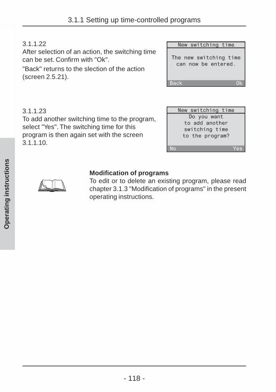
- 118 -
3.1.1 Setting up time-controlled programs
Op
erat
ing
inst
ruct
ion
s
3.1.1.22After selection of an action, the switching timecan be set. Confirm with "Ok"."Back" returns to the slection of the action(screen 2.5.21).
3.1.1.23To add another switching time to the program,select "Yes". The switching time for thisprogram is then again set with the screen3.1.1.10.
Modification of programsTo edit or to delete an existing program, please readchapter 3.1.3 "Modification of programs" in the presentoperating instructions.

- 119 -
3.1.2 Activating and deactivating programs
Op
erat
ing
inst
ruct
ion
s
3.1.2 Activating and deactivating programs
The programs stored in your radio control unit can be activated or deactivatedin accordance with your requirements. To do so, proceed as follows:
3.1.2.1Select "Automatic" in the main menu.
3.1.2.2In the Automatic menu, select "Programactivation".
3.1.2.3The list of stored programs is displayed.Activated programs are marked "✓ ",deactivated programs are marked "-". Thestatus of a program can be changed byselecting the corresponding program with"Select".
Important information
• A newly created program is activated by default.
• Several programs can be active at the same time.The programs are completely independent of eachother.

- 120 -
3.1.3 Changing programs
Op
erat
ing
inst
ruct
ion
s
3.1.3 Changing programs
You can change existing programs at any time to adapt them to yourrequirements. The changes mentioned below will be explained in greaterdetail on the following pages:
- Changing the name of a program Page 121
- Adding a new switching time Page 122
- Deleting an existing switching time Page 123
- Changing the weekdays of a switching time Page 125
- Changing a switching time Page 127
- Selecting another receiver Page 129
- Selecting another action Page 132
- Activating, deactivating or changing the astro time Page 133

- 121 -
3.1.3 Changing programs
Op
erat
ing
inst
ruct
ion
s
Changing the name of a program
3.1.3.1Select "Configuration - Programs" in the menu.The list with all programs stored is displayed.Select the program whose name is to bechanged (in this case: Holidays).
3.1.3.2Select "Change name" in this menu.
3.1.3.3In this screen, the program name can beedited.For entering text, use the 12-key key-pad(cf. fold-out page (3))."Abc" shifts between capital and small letters."<-" deletes the last character. When you haveentered a name, confirm with "Ok".
A brief press on "Back" returns to the previous screen or the next highermenu level.
A long press on "Back" returns to the standard display.
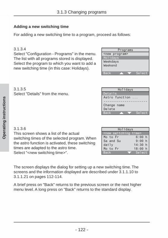
- 122 -
3.1.3 Changing programs
Op
erat
ing
inst
ruct
ion
s
Adding a new switching time
For adding a new switching time to a program, proceed as follows:
3.1.3.4Select "Configuration - Programs" in the menu.The list with all programs stored is displayed.Select the program to which you want to add anew switching time (in this case: Holidays).
3.1.3.5Select "Details" from the menu.
3.1.3.6This screen shows a list of the actualswitching times of the selected program. Whenthe astro function is activated, these switchingtimes are adapted to the astro time.Select "<new switching time>".
The screen displays the dialog for setting up a new switching time. Thescreens and the information displayed are described under 3.1.1.10 to3.1.1.21 on pages 112-114.
A brief press on "Back" returns to the previous screen or the next highermenu level. A long press on "Back" returns to the standard display.

- 123 -
3.1.3 Changing programs
Op
erat
ing
inst
ruct
ion
s
Deleting an existing switching time
To delete a switching time in a program, proceed as follows
3.1.3.7Select "Configuration - Programs" in the menu.The list with all programs stored is displayed.Select the program in which you want to deletea switching time (in this case: Holidays).
3.1.3.8Select "Details" from the menu.
3.1.3.9This screen shows a list of the actualswitching times of the selected program. Whenthe astro function is activated, these switchingtimes are adapted to the astro time. Select theswitching time you want to remove.
3.1.3.10This screen shows all details of the selectedswitching time. Move the cursor to the end ofthe list by pressing ">".
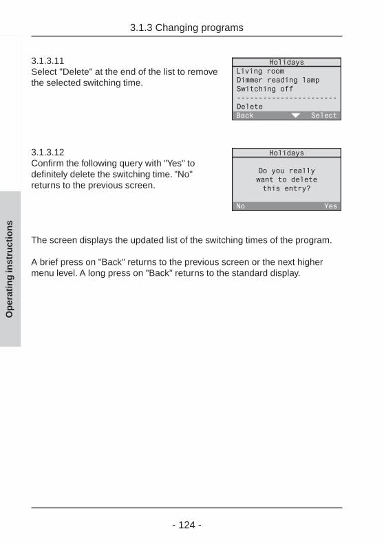
- 124 -
3.1.3 Changing programs
Op
erat
ing
inst
ruct
ion
s
3.1.3.11Select "Delete" at the end of the list to removethe selected switching time.
3.1.3.12Confirm the following query with "Yes" todefinitely delete the switching time. "No"returns to the previous screen.
The screen displays the updated list of the switching times of the program.
A brief press on "Back" returns to the previous screen or the next highermenu level. A long press on "Back" returns to the standard display.
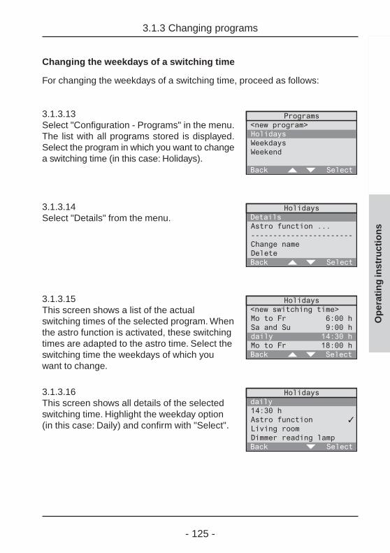
- 125 -
3.1.3 Changing programs
Op
erat
ing
inst
ruct
ion
s
Changing the weekdays of a switching time
For changing the weekdays of a switching time, proceed as follows:
3.1.3.13Select "Configuration - Programs" in the menu.The list with all programs stored is displayed.Select the program in which you want to changea switching time (in this case: Holidays).
3.1.3.14Select "Details" from the menu.
3.1.3.15This screen shows a list of the actualswitching times of the selected program. Whenthe astro function is activated, these switchingtimes are adapted to the astro time. Select theswitching time the weekdays of which youwant to change.
3.1.3.16This screen shows all details of the selectedswitching time. Highlight the weekday option(in this case: Daily) and confirm with "Select".
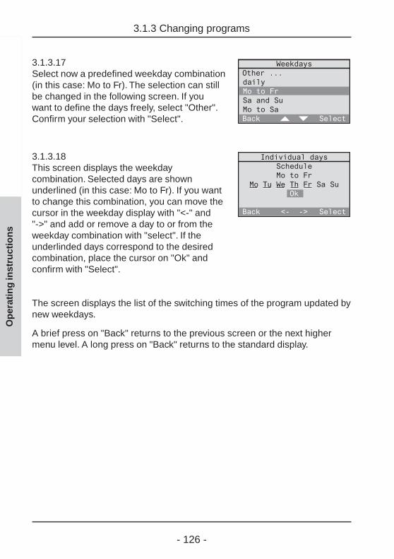
- 126 -
3.1.3 Changing programs
Op
erat
ing
inst
ruct
ion
s
3.1.3.17Select now a predefined weekday combination(in this case: Mo to Fr). The selection can stillbe changed in the following screen. If youwant to define the days freely, select "Other".Confirm your selection with "Select".
3.1.3.18This screen displays the weekdaycombination. Selected days are shownunderlined (in this case: Mo to Fr). If you wantto change this combination, you can move thecursor in the weekday display with "<-" and"->" and add or remove a day to or from theweekday combination with "select". If theunderlinded days correspond to the desiredcombination, place the cursor on "Ok" andconfirm with "Select".
The screen displays the list of the switching times of the program updated bynew weekdays.
A brief press on "Back" returns to the previous screen or the next highermenu level. A long press on "Back" returns to the standard display.

- 127 -
3.1.3 Changing programs
Op
erat
ing
inst
ruct
ion
s
Changing a switching time
For changing a switching time in an existing program, proceed as follows:
3.1.3.19Select "Configuration - Programs" in the menu.The list with all programs stored is displayed.Select the program in which you want to changea switching time (in this case: Holidays).
3.1.3.20Select "Details" from the menu.
3.1.3.21This screen shows a list of the actual switchingtimes of the selected program. When the astrofunction is activated, these switching times areadapted to the astro time. Select the switchingtime you want to change.
3.1.3.22This screen shows all details of the selectedswitching time. Highlight the time (in this case:14:30 h) and confirm with "Select".
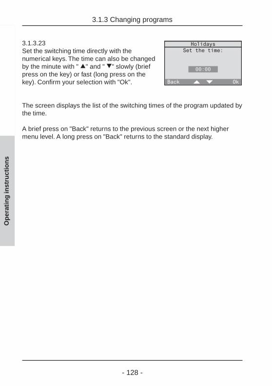
- 128 -
3.1.3 Changing programs
Op
erat
ing
inst
ruct
ion
s
3.1.3.23Set the switching time directly with thenumerical keys. The time can also be changedby the minute with " =" and " >" slowly (briefpress on the key) or fast (long press on thekey). Confirm your selection with "Ok".
The screen displays the list of the switching times of the program updated bythe time.
A brief press on "Back" returns to the previous screen or the next highermenu level. A long press on "Back" returns to the standard display.
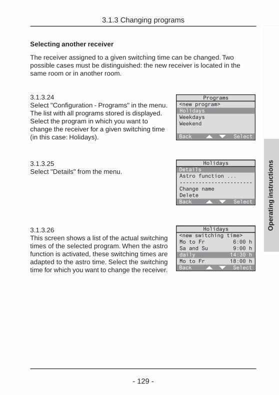
- 129 -
3.1.3 Changing programs
Op
erat
ing
inst
ruct
ion
s
Selecting another receiver
The receiver assigned to a given switching time can be changed. Twopossible cases must be distinguished: the new receiver is located in thesame room or in another room.
3.1.3.24Select "Configuration - Programs" in the menu.The list with all programs stored is displayed.Select the program in which you want tochange the receiver for a given switching time(in this case: Holidays).
3.1.3.25Select "Details" from the menu.
3.1.3.26This screen shows a list of the actual switchingtimes of the selected program. When the astrofunction is activated, these switching times areadapted to the astro time. Select the switchingtime for which you want to change the receiver.

- 130 -
3.1.3 Changing programs
Op
erat
ing
inst
ruct
ion
s
3.1.3.27This screen shows the details of the selectedswitching time.If the new receiver is located in another room,select this room (in this case: Living room).
Continue with screen 3.1.3.28.If the new receiver is located in the sameroom, select the actual receiver(in this case: Lighting).
Continue with screen 3.1.3.29.
3.1.3.28The list of existing rooms is displayed. Selectthe room where the new receiver is located.
3.1.3.29The list of all receiver types existing in yourroom is displayed. Select the type of the newreceiver (in this case: Dimming actuator).
3.1.3.30The list with the receivers of the selected typeexisting in the room is displayed (in this case:Dimming actuators).Select your new receiver.

- 131 -
3.1.3 Changing programs
Op
erat
ing
inst
ruct
ion
s
3.1.3.31The possible actions depending on receivertype (in this case: Dimming actuator) aredisplayed. Select the desired action.
Description of performed actionsThe individual actions are described in the presentoperating instructions in chapter 3.1.1. "Setting uptime-controlled programs" on page 115.

- 132 -
3.1.3 Changing programs
Op
erat
ing
inst
ruct
ion
s
Selecting another action
The action performed at a given switching time in a program can bechanged. Proceed as follows:
3.1.3.32Select "Configuration - Programs" in the menu.The list with all programs stored is displayed.Select the program in which you want tochange the receiver for a given switching time(in this case: Holidays).
3.1.3.33Select "Details" from the menu.
3.1.3.34This screen shows a list of the actual switchingtimes of the selected program. When the astrofunction is activated, these switching times areadapted to the astro time. Select the switchingtime for which you want to change the action tobe performed.
3.1.3.35This screen shows the details of the selectedswitching time.Select the action to be changed at the end ofthe list (in this case: Switching off).
A list with the possible actions that can be selected is displayed. Theremaining procedure is identical with that for "Selecting another receiver"from screen 3.1.3.31 on page 131 onwards.

- 133 -
3.1.3 Changing programs
Op
erat
ing
inst
ruct
ion
s
Activating, deactivating or changing the astro time
You can make the following changes:a) activate or deactivate the astro time in a programb) activate or deactivate the astro time in a given switching timec) change the astro time shift
a) Activating or deactivating the astro time in a program
3.1.3.36Select "Configuration - Programs" in the menu.The list with all programs stored is displayed.Select the program for which you want toactivate or deactivate the astro time(in this case: Holidays).
3.1.3.37aIf astro time is not activated in the selectedprogram, the screen displays "Astro functionoff". Select this item to activate the astrofunction and follow the dialog in 3.1.1.5 to3.1.1.9 (cf. chapter 3.1.1).
3.1.3.37bIf astro time is activated in the selected program,the screen displays "Astro function...".Select this to deactivate the astro function inthe following screen for the whole program.

- 134 -
3.1.3 Changing programs
Op
erat
ing
inst
ruct
ion
s
3.1.3.38Select "Deactivate" to deactivate the astrofunction for this program.
b) Activating or deactivating the astro time for the switching time
If the astro function is activated, the astro function can be activated ordeactivated individually for each switching time of the program.
3.1.3.39Select "Configuration - Programs" in the menu.The list with all programs stored is displayed.Select the program in which you want to activateor deactivate the astro time in individual switch-ing times (in this case: Holidays).
3.1.3.40Select "Details" from the menu.
3.1.3.41This screen shows all stored switching timesof the selected program. These switchingtimes are adapted to the astro time when theastro function is activated. Select the switchingtime in which you want to activate ordeactivate the astro time.

- 135 -
3.1.3 Changing programs
Op
erat
ing
inst
ruct
ion
s
3.1.3.42Select "Astro function". The symbols have thefollowing meaning:
: astro function is activated– : astro function is deactivatedBy pressing "se lect" you can alternate betweenactivated and deactivated for this switching time.
c) Changing the astro time shift
If you want to change the astro time shift in a program, proceed as follows:
3.1.3.43Select "Configuration - Programs" in the menu.The program list showing all programs storedis displayed. Select the program in which youwant to change the astro time shift (in thiscase: Holidays).
3.1.3.44To display an overview of both astro timeshifts, select "Astro function ...".
3.1.3.45Then select the astro time shift you want tochange (in this case: Evening).

- 136 -
3.1.3 Changing programs
Op
erat
ing
inst
ruct
ion
s
3.1.3.46Select the shift directly with the numericalkeys or with "=" en ">". The sign can bechanged with the "*" and also with the "#" key.The maximum shift is ± 120 min. Confirm yourselection with "Ok".
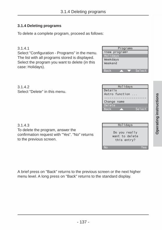
- 137 -
3.1.4 Deleting programs
Op
erat
ing
inst
ruct
ion
s
3.1.4 Deleting programs
To delete a complete program, proceed as follows:
3.1.4.1Select "Configuration - Programs" in the menu.The list with all programs stored is displayed.Select the program you want to delete (in thiscase: Holidays).
3.1.4.2Select "Delete" in this menu.
3.1.4.3To delete the program, answer theconfirmation request with "Yes". "No" returnsto the previous screen.
A brief press on "Back" returns to the previous screen or the next highermenu level. A long press on "Back" returns to the standard display.
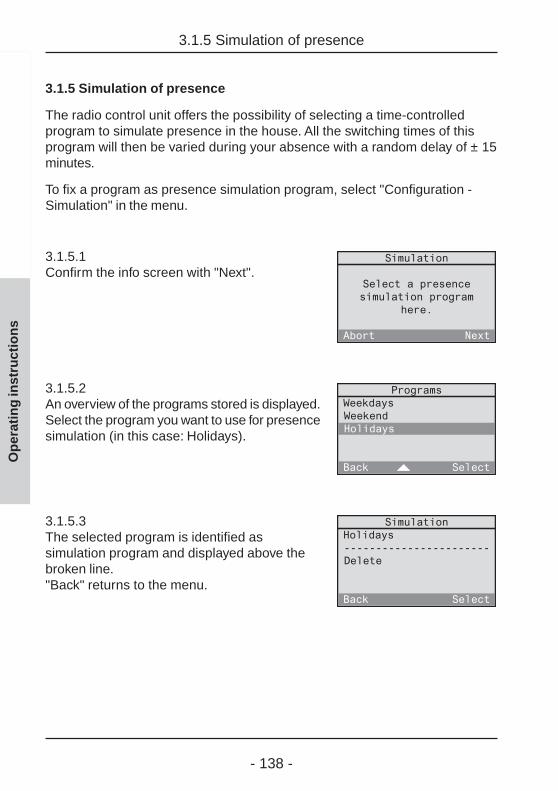
- 138 -
3.1.5 Simulation of presence
Op
erat
ing
inst
ruct
ion
s
3.1.5 Simulation of presence
The radio control unit offers the possibility of selecting a time-controlledprogram to simulate presence in the house. All the switching times of thisprogram will then be varied during your absence with a random delay of ± 15minutes.
To fix a program as presence simulation program, select "Configuration -Simulation" in the menu.
3.1.5.1Confirm the info screen with "Next".
3.1.5.2An overview of the programs stored is displayed.Select the program you want to use for presencesimulation (in this case: Holidays).
3.1.5.3The selected program is identified assimulation program and displayed above thebroken line."Back" returns to the menu.

- 139 -
3.1.5 Simulation of presence
Op
erat
ing
inst
ruct
ion
s
Changing or deleting the presence simulation program
To fix another program as presence simulation program, select the oldprogram (in this case: Holidays) in screen 3.1.5.3. You are then taken back toscreen 3.1.5.2 from where another program can be selected.
To delete the selected program as presence simulation program, select"Delete" in screen 3.1.5.3. The program as such is not deleted and continuesto be available as a normal program without simulation function.
Activating and deactivating of the presence simulation function
A program defined as presence simulation program is activated by theleaving function and deactivated by the returning (welcome) function,independent of whether the program is activated or deactivated in theprogram list.
Read chapter 5.2 "The returning (welcome) / leavingfunction".
- 140 -
Operating instructions

- 141 -
3.2 Setting up logic links
Op
erat
ing
inst
ruct
ion
s
3.2 Setting up logic links
A logic link can be used to control a receiver from a transmitter via the radiocontrol unit. This logic link can be set up in such a way that it is dependenton time and/or the status of another transmitter.
Example 1:The switching actuator in the study can only be switched from the hand trans-mitter, if wall transmitter channel 1 in the hallway is activated (central function).As another condition, switching is to be possible only from Monday thru Fridaybetween 18:00h and 23:00h.
Example 2:The smoke detector is to switch on the light in the bedroom via the radiocontrol unit in the event of smoke alarm.
The following description makes use of different terms which are definedhere with reference to example 1:
Receiver (logic link): in this case switching actuator in the study
A logic link includes a receiver which can perform an action defined by acontrol set. Each receiver can be assigned several control sets which arelinked by a logic OR.
Control set:The term "control set" includes the following elements:
Time (time of day and weekdays) Condition (state of transmitter) Initiator (transmitter) Action (only with presence detector or monitor)
Time: in this case Monday thru Friday between 18:00h and 23:00h
The weekdays and the duration during which the logic link can be activated.If starting and ending time are set to 00:00h, the duration is taken as a fullday (24 hours).
- 142 -
3.2 Setting up logic links
Op
erat
ing
inst
ruct
ion
s
Condition (transmitter status): in this case wall transmitter channel 1 active
The receiver can only be activated if the condition is fulfilled. A conditionalways implies a certain transmitter status.A logic link must not necessarily include a condition.
Initiator (transmitter): in this case hand transmitter
The transmitter triggering an action in your receiver, if time requirementsand, if applicable, also the condition are fulfilled.
Action:If a presence detector or a monitor has been selected as an initiator(transmitter), the action to be performed can also be chosen freelydepending on the type of receiver.In all other cases (e.g. channel key or light-scene of a hand transmitter) noaction can be chosen, as the key-specific function will be executed.
Important information
• The "dimming" and "slat adjustment" functions arenot supported by logic links. The dimming level orshutter position functions can be used instead.
• The "All-On" and "All-Off" keys should not be usedas initiator or condition as the long transmit times(up to about 12 seconds) may cause delayedreactions.
The following chapters explain how to
- set up (chapter 3.2.1)- activate (chapter 3.2.2)- deactivate (chapter 3.2.2)- change (chapter 3.2.3)- delete (chapter 3.2.4)
logic links.

- 143 -
Op
erat
ing
inst
ruct
ion
s
3.2.1 Setting up logic links
3.2.1 Setting up logic links
Your electrical fitter may already have installed some initial logic links in yourradio control unit. You can, however, add further logic links in accordance withyour personal needs.
This is done with the help of the initial start-up dialog "new logic links" whichcan be called up in the main menu under "Configuration – Logic links –<New logic link>".
To set up a new logic link, follow the dialog instructions on the display of yourradio control unit.
Fig. 3.d: Logic link set-up sequence

- 144 -
3.2.1 Setting up logic links
Op
erat
ing
inst
ruct
ion
s
3.2.1.1Confirm the info text for setting up a new logiclink with "Next"."Abort" returns to the main menu.
3.2.1.2The logic link must first be given a name.Confirm the info text with "Next"."Abort" returns to the main menu.
3.2.1.3Select a new name for the logic link from thelist or select <New name> to define a newname for the logic link. Confirm your selectionwith "Select"."Back" returns to the previous screen.
3.2.1.4In this screen, the selected name can beedited or the new name entered. The namemay consist of up to 16 characters.For entering text, use the keypad (see fold-outpage (3))."Abc" shifts between capital and small letters."<-" deletes the last character. When you haveentered a name, confirm with "Ok".
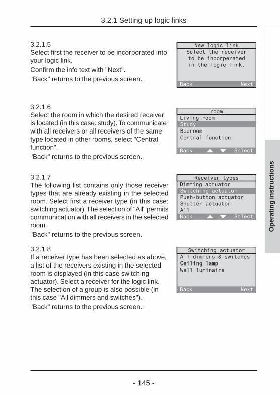
- 145 -
3.2.1 Setting up logic links
Op
erat
ing
inst
ruct
ion
s
3.2.1.5Select first the receiver to be incorporated intoyour logic link.Confirm the info text with "Next"."Back" returns to the previous screen.
3.2.1.6Select the room in which the desired receiveris located (in this case: study). To communicatewith all receivers or all receivers of the sametype located in other rooms, select "Centralfunction"."Back" returns to the previous screen.
3.2.1.7The following list contains only those receivertypes that are already existing in the selectedroom. Select first a receiver type (in this case:switching actuator). The selection of "All" permitscommunication with all receivers in the selectedroom."Back" returns to the previous screen.
3.2.1.8If a receiver type has been selected as above,a list of the receivers existing in the selectedroom is displayed (in this case switchingactuator). Select a receiver for the logic link.The selection of a group is also possible (inthis case "All dimmers and switches")."Back" returns to the previous screen.
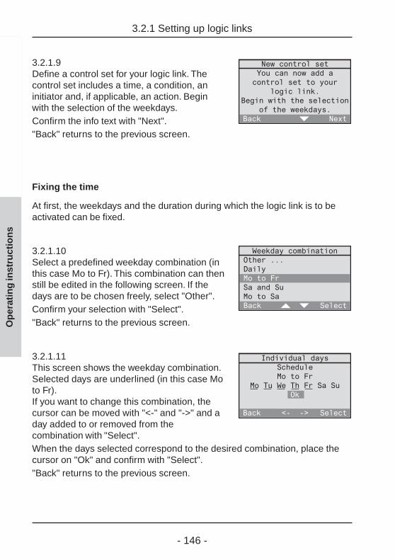
- 146 -
Op
erat
ing
inst
ruct
ion
s
3.2.1.9Define a control set for your logic link. Thecontrol set includes a time, a condition, aninitiator and, if applicable, an action. Beginwith the selection of the weekdays.Confirm the info text with "Next"."Back" returns to the previous screen.
Fixing the time
At first, the weekdays and the duration during which the logic link is to beactivated can be fixed.
3.2.1.10Select a predefined weekday combination (inthis case Mo to Fr). This combination can thenstill be edited in the following screen. If thedays are to be chosen freely, select "Other".Confirm your selection with "Select"."Back" returns to the previous screen.
3.2.1.11This screen shows the weekday combination.Selected days are underlined (in this case Moto Fr).If you want to change this combination, thecursor can be moved with "<-" and "->" and aday added to or removed from thecombination with "Select".When the days selected correspond to the desired combination, place thecursor on "Ok" and confirm with "Select"."Back" returns to the previous screen.
3.2.1 Setting up logic links

- 147 -
Op
erat
ing
inst
ruct
ion
s
3.2.1.12After selection of the weekdays, fix next theduration limited by the control set starting andending times. Begin with the starting time.Confirm the info text with "Next"."Back" returns to the previous screen.
3.2.1.13Set the starting time directly with the numericalkeys.As an alternative, the time can also be changedslowly by the minute with "=" and ">" (shortpress on the key) or fast (long press on thekey). Confirm your selection with "Ok"."Back" returns to the previous screen.
3.2.1.14In the next step, the ending time must be set.Confirm the info text with "Next"."Back" returns to the previous screen.
3.2.1.15Set the ending time. If starting and endingtimes are both set to 00:00h, the duration ofthe ON time corresponds to a full day (24 h).
3.2.1 Setting up logic links
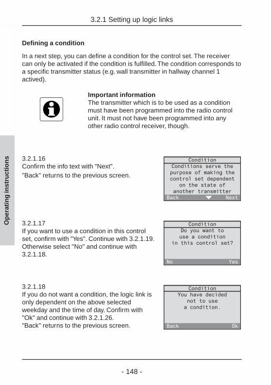
- 148 -
Op
erat
ing
inst
ruct
ion
s
Defining a condition
In a next step, you can define a condition for the control set. The receivercan only be activated if the condition is fulfilled. The condition corresponds toa specific transmitter status (e.g. wall transmitter in hallway channel 1actived).
Important informationThe transmitter which is to be used as a conditionmust have been programmed into the radio controlunit. It must not have been programmed into anyother radio control receiver, though.
3.2.1.16Confirm the info text with "Next"."Back" returns to the previous screen.
3.2.1.17If you want to use a condition in this controlset, confirm with "Yes". Continue with 3.2.1.19.Otherwise select "No" and continue with3.2.1.18.
3.2.1.18If you do not want a condition, the logic link isonly dependent on the above selectedweekday and the time of day. Confirm with"Ok" and continue with 3.2.1.26."Back" returns to the previous screen.
3.2.1 Setting up logic links

- 149 -
Op
erat
ing
inst
ruct
ion
s
2.6 Setting up logic links
3.2.1.19If you want to use a condition, you must firstselect the radio control transmitter. Confirmthe info text with "Next".Important: A radio control detector and asmoke detector with radio control module isnot suitable for use as a condition.
3.2.1.20Select the room where the desired transmitteris located (in this case: hallway)."Back" returns to the previous screen.
3.2.1.21The following list contains only types oftransmitters already existing in the selectedroom. Select first a transmitter type (in thiscase: wall transmitter). Depending on theselected transmitter, observe also theinstructions on the following page."Back" returns to the previous screen.
3.2.1.22A list with the transmitters existing in thedesired room (in this case: wall transmitters)appears. Select the transmitter that is to serveas a condition."Back" returns to the previous screen.
3.2.1.23In the next step, select first the channel andthen the status of the transmitter.Confirm the info text with "Next"."Back" returns to the previous screen.

- 150 -
Op
erat
ing
inst
ruct
ion
s
3.2.1.24Select the transmitter channel. The selectionshown is dependent on the previouslyselected transmitter."Back" returns to the previous screen.
3.2.1.25Finish by selecting the status fulfilling thecondition."Back" returns to the previous screen.
Important information for presence detectorsWhen a presence detector is selected as a condition,the latter is fulfilled, if it is "too bright" or "too dark"with respect to the brightness reference value preseton the presence detector.
3.2.1 Setting up logic links

- 151 -
Op
erat
ing
inst
ruct
ion
s
3.2.1 Setting up logic links
Selecting an initiator (transmitter)
The following screens can be used to define the initiator of the control set.The initiator is the transmitter that triggers an action in your receiver, if thetime falls into the ON-duration and if also the condition (if defined) is fulfilled.
3.2.1.26Confirm the info text with "Next"."Back" returns to the previous screen.
3.2.1.27If you want to use an initiator in this controlset, confirm with "Yes". In this case, continuewith 3.2.1.29. Otherwise, select "No" andcontinue with 3.2.1.30.
3.2.1.28If no initiator is used, the action is directlyperformed in the receiver by the condition.Confirm with "Ok" and continue with 3.2.1.35."Back" returns to the previous screen.
3.2.1.29Select the initator (transmitter) which is totrigger the action in your receiver if thecondition is fulfilled.
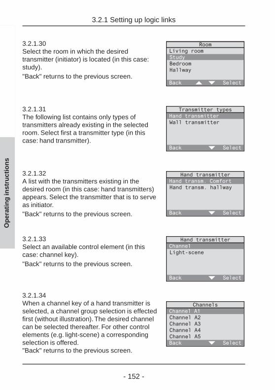
- 152 -
Op
erat
ing
inst
ruct
ion
s
3.2.1.30Select the room in which the desiredtransmitter (initiator) is located (in this case:study)."Back" returns to the previous screen.
3.2.1.31The following list contains only types oftransmitters already existing in the selectedroom. Select first a transmitter type (in thiscase: hand transmitter).
3.2.1.32A list with the transmitters existing in thedesired room (in this case: hand transmitters)appears. Select the transmitter that is to serveas initiator."Back" returns to the previous screen.
3.2.1.33Select an available control element (in thiscase: channel key)."Back" returns to the previous screen.
3.2.1.34When a channel key of a hand transmitter isselected, a channel group selection is effectedfirst (without illustration). The desired channelcan be selected thereafter. For other controlelements (e.g. light-scene) a correspondingselection is offered."Back" returns to the previous screen.
3.2.1 Setting up logic links

- 153 -
Op
erat
ing
inst
ruct
ion
s
3.2.1 Setting up logic links
Selecting an action
When a presence detector, monitor or a smoke detector has been selectedas the initiator (transmitter), the action to be performed can be freely chosendepending on the receiver.
Otherwise, the following relationships apply:
- If a specific receiver and a channel or light-scene key have beenselected, no action can be chosen as the respective function (e.g.switching on / off, light-scene 3) is directly executed.
- If "All" was selected in the receiver types screen and if a channel key hasbeen fixed as the initiator, no action can be chosen as the leaving /welcome function is directly executed.
3.2.1.35Confirm the info text with "Next"."Back" returns to the previous screen.The screen displays a selection of possibleactions or otherwise the info that no action canbe chosen.
3.2.1.36The control set for the selected radio controlreceiver is now defined. It is also possible todefine further control sets for this receiver. Inthis case, confirm with "Yes". The definition ofa new control sets begins again with screen3.2.1.9. "No" returns to the menu.
Changing logic linksTo edit or to delete an existing logic link, read chapter3.2.3 "Changing logic links" in the operatinginstructions.

- 154 -
Op
erat
ing
inst
ruct
ion
s
3.2.2 Activating and deactivating logic links
3.2.2 Activating and deactivating logic links
The logic links stored in the radio control unit can be activated or deactivatedin acc. with your requirements. To do so, proceed as follows:
3.2.2.1Select "Automatic mode" in the main menu.
3.2.2.2Select "Logic links" in the Automatic menu.
3.2.2.3The list of stored logic links is displayed.Activated logic links are marked "✓ ",deactivated ones are marked "-". The status ofthe logic link can be changed by selecting thelink with "Select".
Important information
• A newly established logic link is activated bydefault.
• Several logic links may be active at the same time.The links are completely independent of eachother.

- 155 -
Op
erat
ing
inst
ruct
ion
s
3.2.3 Changing logic links
3.2.3 Changing logic links
You can change existing logic links at any time to adapt them to yourrequirements. The changes mentioned below will be explained in greaterdetail on the following pages:
- Changing the name of a logic link Page 156
- Adding a new control set Page 157
- Deleting an existing control set Page 158
- Changing the receiver in the logic link Page 159
- Changing the time of the logic link Page 160
- Changing the condition (transmittter status) Page 160
- Changing the initiator (transmitter) Page 160
- Changing the action to be performed Page 160
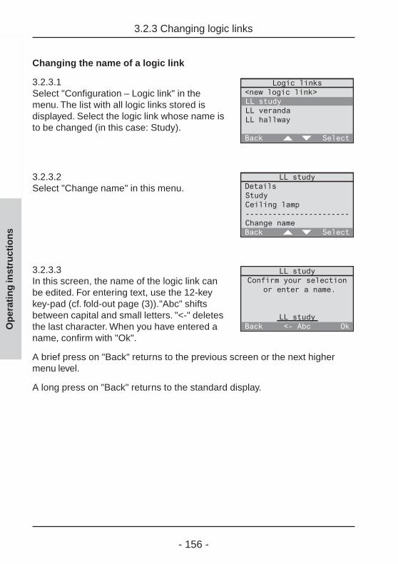
- 156 -
Op
erat
ing
inst
ruct
ion
s
3.2.3 Changing logic links
Changing the name of a logic link
3.2.3.1Select "Configuration – Logic link" in themenu. The list with all logic links stored isdisplayed. Select the logic link whose name isto be changed (in this case: Study).
3.2.3.2Select "Change name" in this menu.
3.2.3.3In this screen, the name of the logic link canbe edited. For entering text, use the 12-keykey-pad (cf. fold-out page (3))."Abc" shiftsbetween capital and small letters. "<-" deletesthe last character. When you have entered aname, confirm with "Ok".
A brief press on "Back" returns to the previous screen or the next highermenu level.
A long press on "Back" returns to the standard display.

- 157 -
Adding a new control set
3.2.3.4Select "Configuration – Logic link" in the menu.The list with all logic links stored is displayed.Select the logic link to which you want to add anew control set (in this case: Study).
3.2.3.5Select "Details" from the menu.
3.2.3.6This screen shows a list of the actual controlsets. Select <New control set > to add a newcontrol set to the logic link.
To add the new control set, proceed in acc. with the instructions of screens3.2.1.9 to 3.2.1.34.
Op
erat
ing
inst
ruct
ion
s
3.2.3 Changing logic links

- 158 -
Op
erat
ing
inst
ruct
ion
s
3.2.3 Changing logic links
Deleting an existing control set
3.2.3.7Select "Configuration – Logic links" in the menu.The list with all logic links stored is displayed.Select the logic link in which you want to deletea control set (in this case: Study).
3.2.3.8Select "Details" from the menu.
3.2.3.9This screen shows a list of the actual controlsets. Select the control set you want to remove(in this case: Control set 2).
3.2.3.10To delete the control set, select "Delete" at theend of the screen. Answer the subsequentconfirmation request with "Yes".
A brief press on "Back" returns to the previous screen or the next highermenu level.
A long press on "Back" returns to the standard display.

- 159 -
Changing the receiver in the logic link
You can change the receiver in an existing logic link. The new receiver maybe located in the same room or in another room.
Important informationTo ensure proper functioning of the logic link after thechange, the new receiver must be of the same type asthe old one (e.g. switching actuator). If this is not thecase, it is recommended to set up a new logic link.
3.2.3.11Select "Configuration – Logic links" in the menu.The list with all logic links stored is displayed.Select the logic link in which you want tochange the receiver (in this case: Study).
3.2.3.12If the new receiver is located in another room,select the corresponding room (in this case:Study). At first, a list of all available rooms isdisplayed and then a list of the receivers of thesame type (e.g. all switching actuators).
If the new receiver is located in the sameroom, select directly the old receiver (in thiscase: Ceiling lamp). The list of receivers of thesame type available in this room is displayed.
A brief press on "Back" returns to the previous screen or the next highermenu level. A long press on "Back" returns to the standard display.
Op
erat
ing
inst
ruct
ion
s
3.2.3 Changing logic links
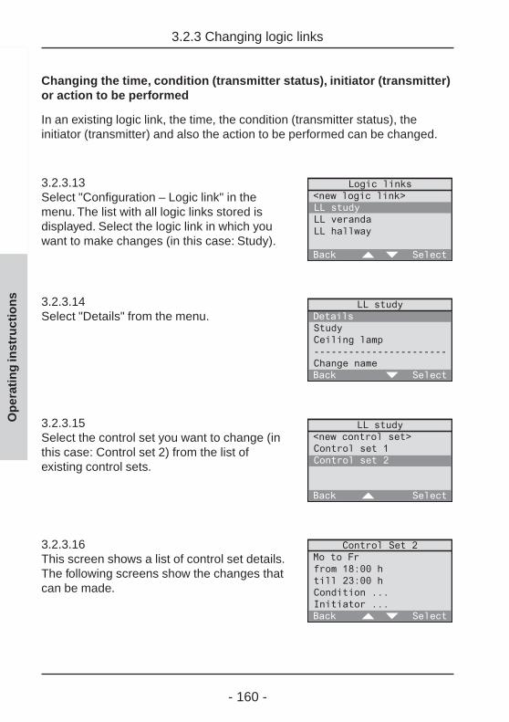
- 160 -
Op
erat
ing
inst
ruct
ion
s
3.2.3 Changing logic links
Changing the time, condition (transmitter status), initiator (transmitter)or action to be performed
In an existing logic link, the time, the condition (transmitter status), theinitiator (transmitter) and also the action to be performed can be changed.
3.2.3.13Select "Configuration – Logic link" in themenu. The list with all logic links stored isdisplayed. Select the logic link in which youwant to make changes (in this case: Study).
3.2.3.14Select "Details" from the menu.
3.2.3.15Select the control set you want to change (inthis case: Control set 2) from the list ofexisting control sets.
3.2.3.16This screen shows a list of control set details.The following screens show the changes thatcan be made.
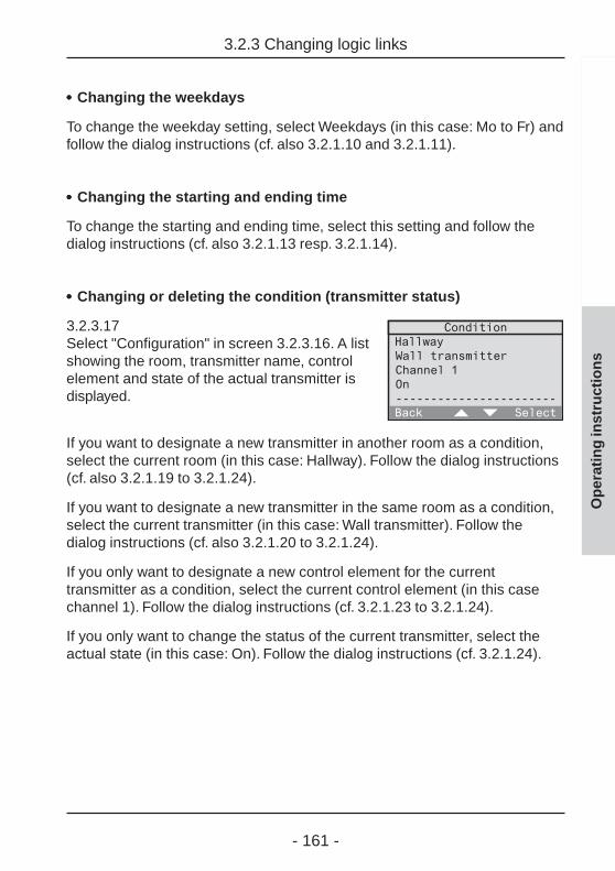
- 161 -
••••• Changing the weekdays
To change the weekday setting, select Weekdays (in this case: Mo to Fr) andfollow the dialog instructions (cf. also 3.2.1.10 and 3.2.1.11).
••••• Changing the starting and ending time
To change the starting and ending time, select this setting and follow thedialog instructions (cf. also 3.2.1.13 resp. 3.2.1.14).
••••• Changing or deleting the condition (transmitter status)
3.2.3.17Select "Configuration" in screen 3.2.3.16. A listshowing the room, transmitter name, controlelement and state of the actual transmitter isdisplayed.
If you want to designate a new transmitter in another room as a condition,select the current room (in this case: Hallway). Follow the dialog instructions(cf. also 3.2.1.19 to 3.2.1.24).
If you want to designate a new transmitter in the same room as a condition,select the current transmitter (in this case: Wall transmitter). Follow thedialog instructions (cf. also 3.2.1.20 to 3.2.1.24).
If you only want to designate a new control element for the currenttransmitter as a condition, select the current control element (in this casechannel 1). Follow the dialog instructions (cf. 3.2.1.23 to 3.2.1.24).
If you only want to change the status of the current transmitter, select theactual state (in this case: On). Follow the dialog instructions (cf. 3.2.1.24).
Op
erat
ing
inst
ruct
ion
s
3.2.3 Changing logic links

- 162 -
Op
erat
ing
inst
ruct
ion
s
3.2.3 Changing logic links
You can also delete the complete condition. In this case, the control set isdefined only by the weekday and the time of day already selected.To delete the condition, select "Delete" at the end of screen 3.2.3.17. Answerthe subsequent confirmation request with "Yes".
Screen 3.2.3.16 indicates the status behind the term "Condition" by meansof the following signs:
---no condition existing... condition existing
••••• Changing the initiator (transmitter)
3.2.3.18Select "Initiator" in screen 3.2.3.16. Anoverview showing the room, transmitter nameand control element of the current initiator isdisplayed.
If you want to designate a new transmitter in another room as an initiator,select the current room (in this case: Study). Follow the dialog instructions(cf. also 3.2.1.29 to 3.2.1.33).
If you want to designate a new transmitter in the same room as an initiator,select the current transmitter (in this case: Hand transmitter). Follow thedialog instructions (cf. also 3.2.1.30 to 3.2.1.33)
If you only want to designate a new control element for the current transmitteras a condition, select the current control element (in this case: channel A1).Follow the dialog instructions (cf. 3.2.1.32 to 3.2.1.33).
You can also delete the complete initiator. In this case, the action performedby the receiver is directly controlled by the condition.To delete the initiator, select "Delete" at the end of screen 3.2.3.18. Answerthe subsequent confirmation request with "Yes".
Screen 3.2.3.16 indicates the status behind the term "Initiator" by means ofthe following signs:
---no initiator existing... initiator existing

- 163 -
••••• Changing the action to be performed
3.2.3.19If a presence detector or monitor is selectedas an initiator, the action to be performed canbe changed as well. Select the current action(in this case: On). A list of alternative actionsis displayed.
3.2.3.20If another transmitter is designated as initiator,no action can be chosen, as the activatedfunction will be executed (e.g. short key-press
switching).In the detailed list, this is marked as "<standard>".
Op
erat
ing
inst
ruct
ion
s
3.2.3 Changing logic links

- 164 -
Op
erat
ing
inst
ruct
ion
s
3.2.4 Deleting logic links
3.2.4 Deleting logic links
Logic links can be deleted completely. To do so, proceed as follows:
3.2.4.1Select "Configuration – Logic links" in themenu. The list with all logic links stored isdisplayed. Select the logic link you want todelete (in this case: Study).
3.2.4.2Select "Delete" at the end of the menu.
3.2.4.3To delete the logic link, answer the confirmationrequest with "Yes". "No" returns to the previousscreen.
A brief press on "Back" returns to the previous screen or the next highermenu level. A long press on "Back" returns to the standard display.

- 165 -
3.3 Working with light-scenes
All radio control receivers programmed into the radio control unit canaccomodate 5 light-scenes.
Lighting actuators (dimming and switching actuators) can be programmedfor a specific brightness level (e.g. 70 %) or switching state (e.g. On) in alight-scene.
Shutter actuators can be programmed for a limit stop position (completely upor completely down) in a light-scene.
Light-scenes can be stored and recalled for all the rooms or for each roomindividually. They can moreover be stored and recalled completely orseparately for lighting actuators (dimming and switching actuators) or forshutter actuators.
Application examples:
In your dining room, you have a dimmable ceiling lamp and a dimmablereading lamp. The room also has two shutters (shutter facing north andshutter facing south).When the TV is running, the ceiling lamp is to be at 50% brightness and thereading lamp at approximately 30% brightness. The shutter facing south islowered whereas the shutter facing north is still up.
These settings and positions can be stored completely or separately forlighting and for shutters in the radio control unit in a light-scene which can berecalled or also modified at any time.
Op
erat
ing
inst
ruct
ion
s
3.3 Working with light-scenes

- 166 -
Op
erat
ing
inst
ruct
ion
s
3.3 Working with light-scenes
In addition, the light-scenes labelled "All-On" and "All-Off" are also availablefor each room. These scenes are predefined for lighting purposes. Whenrecalled, all lighting actuators (switching and dimming actuators) in a roomare switched on or off. These scenes can be modified, if necessary.
The 5 light-scenes and also "All-On" and "All-Off" can be programmed withshutter actuators only for the limit-stop positions (completely up or completelydown).
Important information:The values for light-scenes 1-5 and the All-On and All-Off functions stored and recalled via the radio controlunit are the same as those recalled from or stored inanother radio control transmitter (e.g. hand transmitter).

- 167 -
3.3.1 Storing and changing light-scenes
A light-scene or also an "All-On" or "All-Off function" can be changed andstored completely or separately as desired for individual rooms. In addition,you can also change and store only the settings for lighting actuators orshutter actuators.
Information for shuttersWith shutter actuators, only the limit-stop positions ofthe shutter (completely up or completely down) can bestored in light-scenes. If the shutter is not in its limit-stop position or on its way to this position duringstoring of a light-scene, the corresponding shuttercannot be stored in this light-scene.
Information for 1-channel UP switching actuatorIf a 1-channel UP radio switching actuator which is notlabelled at least R2 (see device rating plate) is used inyour radio control system, note the following specialreactions:
If light-scenes are stored in this switching actuator viathe radio control unit, the actuator always saves the"Off" state.To save the "On" state for the light-scene, the scenemust be stored with another radio control transmitter(e.g. radio control hand transmitter). Read the operatinginstructions of the corresponding radio control transmitter.
Op
erat
ing
inst
ruct
ion
s
3.3.1 Storing and changing light-scenes

- 168 -
Op
erat
ing
inst
ruct
ion
s
3.3.1 Storing and changing light-scenes
Procedure
Start by setting the light-scene for lighting actuators and/or shutter actuators inthe desired area (room or all rooms) in accordance with your requirements.
3.3.1.1Select "Configuration – Save light-scene" inthe menu.
3.3.1.2A list with the available rooms is displayed.Select the room for which you want to changeand store a light-scene. The selection of"Central function" permits changing andstoring a light-scene for more than one room.
3.3.1.3Select now whether you want to change andstore the light-scene for all actuators or onlyfor the lighting or the shutter actuators.
3.3.1.4Select finally the light-scene you want to store.The list offers light-scenes 1-5, All-On and All-Off.

- 169 -
Op
erat
ing
inst
ruct
ion
s
3.3.1 Storing and changing light-scenes
3.3.1.5Before storing the light-scene make sure onceagain that the corresponding actuators areadjusted as desired. Then, confirm with "Ok".
A short tone can be heard and the light-scene is stored. This will take youback to screen 3.3.1.3 for changing and storing further light-scenes in theselected area.
A brief press on "Back" returns to the previous screen or the next highermenu level. A long press on "Back" returns to the standard display.

- 170 -
Op
erat
ing
inst
ruct
ion
s
3.3.2 Recalling light-scenes
3.3.2 Recalling light-scenes
All stored light-scenes (including All-On and All-Off) can be recalled for eachroom and separately for lighting and shutter via the menu or user-definedhotkeys on the keypad.
Recalling light-scenes via the menu
To recall light-scenes via the menu, select first "Automatic – Light-scenes" inthe menu.
3.3.2.1A list with available rooms is displayed. Selectthe room in which you want to recall a light-scene. Select "Central function" if you want torecall a light-scene for more than room.
3.3.2.2Select now whether you want to recall thelight-scene for all actuators or for the lightingor the shutter actuators only.
3.3.2.3Select finally the light-scene you want torecall. The list offers light-scenes 1-5, All-Onand All-Off.

- 171 -
Op
erat
ing
inst
ruct
ion
s
3.3.2 Recalling light-scenes
The light-scene is recalled and you are taken back to screen 3.3.2.2 forrecalling further light-scenes in the selected area.
A brief press on "Back" returns to the previous screen or the next highermenu level. A long press on "Back" returns to the standard display.
Recalling light-scenes via hotkeys
Often used light-scenes can be programmed on one of the numerical keys0-9 of keypad (3) and then be recalled directly via hotkey.
3.3.2.4To program a light-scene on a numerical key,mark first the light-scene as shown in screens3.3.2.1 to 3.3.2.3 (in this case: Light-scene 3).Depress the desired numerical key (ca. 1 s)until a short tone is heard.The key is now programmed.
To recall a light-scene by user-defined hotkey, the radio control unit mustdisplay the standard screen (see fold-out page). For recalling the light-scene,depress the desired numerical key briefly.

- 172 -
Op
erat
ing
inst
ruct
ion
s
4.0 Manual operation
4.0 Manual operation
A programmed radio control receiver can also be addressed via the menu ordirectly by pressing a hotkey on the keypad independently of runningprograms. The receiver can also be made to execute an action.
Controlling a receiver via the menu
To control a programmed radio control receiver via the menu, select first"Actions" in the menu.
4.0.1The next screen lists the rooms where radiocontrol reveivers are installed. Select the room inwhich you want to control a radio receiver (in thiscase: Study). To control receicvers of the sametype also in other rooms, select "Central function".
4.0.2A list showing the receiver types installed in theselected room is displayed. Select the receivertype you want operate (in this case: dimmingactuator). The selection of "All" permits callingup directly the Returning (welcome) / Leavingfunction.
4.0.3Select the desired receiver from the list. Withdimming, switching or push-button actuatorsyou are always offered the "All dimmers &switches" option.
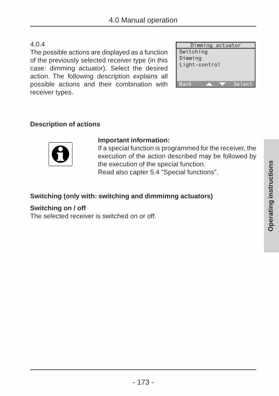
- 173 -
Op
erat
ing
inst
ruct
ion
s
4.0 Manual operation
4.0.4The possible actions are displayed as a functionof the previously selected receiver type (in thiscase: dimming actuator). Select the desiredaction. The following description explains allpossible actions and their combination withreceiver types.
Description of actions
Important information:If a special function is programmed for the receiver, theexecution of the action described may be followed bythe execution of the special function.Read also capter 5.4 "Special functions".
Switching (only with: switching and dimmimng actuators)
Switching on / offThe selected receiver is switched on or off.

- 174 -
Op
erat
ing
inst
ruct
ion
s
4.0 Manual operation
Dimming (only with: dimming actuators)
Dimming levelThe actuator can be adjusted to a specificdimming level. Adjust the dimming leveldirectly with the numerical keys or with "="and ">".When "Ok" is pressed once, the corres-ponding receiver switches to the selecteddimming level for approval.When "Ok" is pressed a second time, thedimming level is stored and the screen dis-appears. "Back" returns to the previous screen.
Momentary contact function (only with: push-button actuators)
ActuateThe selected push-button actuator transmits a short pulse.
Shutter (only with: shutter actuators)
Limit-stop position – top / bottomThe selected shutter is moved into the upper or lower limit-stop position.
Movement - positionThe selected shutter can be moved into aspecific position, if the shutter moving timehas been defined beforehand (cf. chapter2.3). 0 % corresponds to "completely up"and 100 % to "completely down". Adjust theshutter position directly with the numericalkeys or with "=" and ">".When "Ok" is pressed once, the corresponding actuator moves theshutter to the selected position for approval.When "Ok" is pressed a second time, the position is stored and the screendisappears. "Back" returns to the previous screen.

- 175 -
Op
erat
ing
inst
ruct
ion
s
4.0 Manual operation
Presence (only with: All)
LeavingThe last brightness values of the lighting and the shutter end positions arestored before the All-Off telegram is transmitted.
ReturningDepending on the defined special functions (delay, action) of the radio-control receiver, 3 types of reactions are available:- Delay: 0 min; action: <none>
The value stored before leaving is restored on returning. Observe alsothe information in chapter 5.4.
- Delay: 0 min; action: definedThe defined action is performed on return.
- Delay: > 0 min; action: definedAt first, the value stored before leaving is restored on returning. Thedefined action is then performed at the end of the delay.
Read also chapter 5.2 "The leaving / returning function" in the operatinginstructions.
Light control (only with: switching and dimming actuators)
Light control on /offIf a radio-control presence detector has been programmed into thereceiver, the light control can be activated or deactivated here. Any otheraction transmitted by the radio control unit deactives an active light control.
Adopting the lux valueIf a radio presence detector has been programmed into the selectedreceiver, the actual brightness value can be stored in the actuator asbrightness reference value (lux value) for the light control function.
- 176 -
Op
erat
ing
inst
ruct
ion
s
4.0 Manual operation
Controlling receivers via hotkey
Often needed actions can be programmed on one of the numerical keys 0-9of keypad (3) for direct recall via hotkey. The following two actions cannot beactivated by hotkey as they both need a percentage as input:
- dimming – dimming level- shutter - movement - position
To program an action on a numerical key, selelct first the action in screens 4.0.1to 4.0.4 and mark them. Then, depress the desired numerical key (ca. 1 s) untila short tone is heard.Programming of the key is terminated.
To recall an action by user-defined hotkey, the radio control unit must displaythe standard screen (see fold-out page). For recalling the action, depress thedesired numerical key briefly.
Important information:You can also control your radio receivers directly withradio transmitters independent of the radio control unit.To do so, the transmitter must have been programmedbeforehand into the corresponding receivers (read theoperating instructions of the corresponding product).
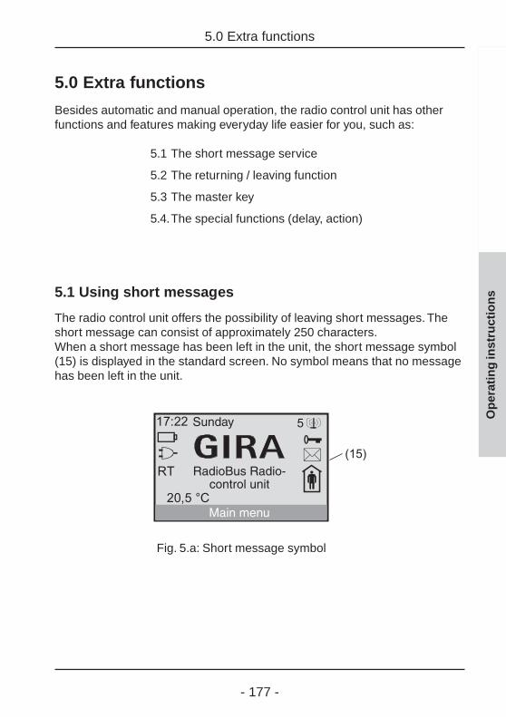
- 177 -
Op
erat
ing
inst
ruct
ion
s
5.0 Extra functions
5.0 Extra functions
Besides automatic and manual operation, the radio control unit has otherfunctions and features making everyday life easier for you, such as:
5.1 The short message service
5.2 The returning / leaving function
5.3 The master key
5.4.The special functions (delay, action)
5.1 Using short messages
The radio control unit offers the possibility of leaving short messages. Theshort message can consist of approximately 250 characters.When a short message has been left in the unit, the short message symbol(15) is displayed in the standard screen. No symbol means that no messagehas been left in the unit.
Fig. 5.a: Short message symbol
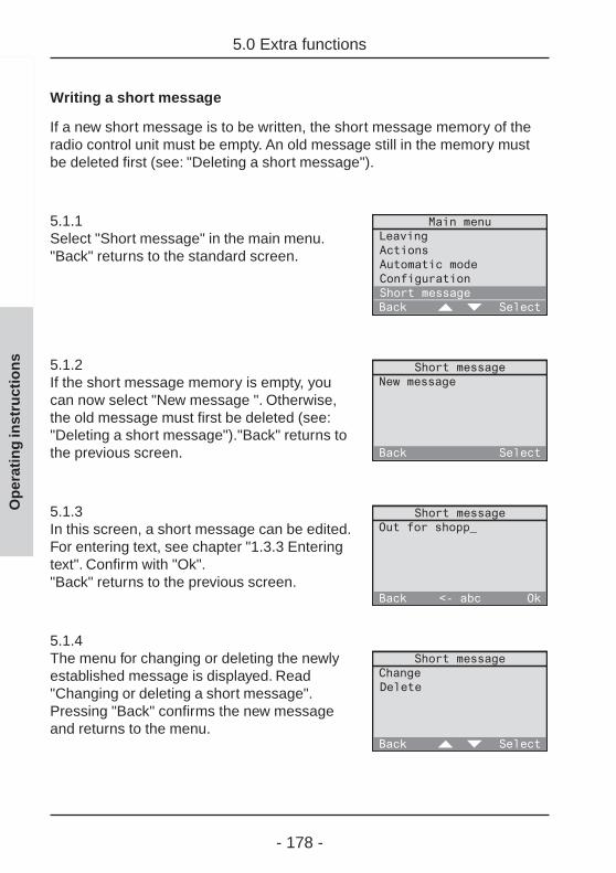
- 178 -
Op
erat
ing
inst
ruct
ion
s
5.0 Extra functions
Writing a short message
If a new short message is to be written, the short message memory of theradio control unit must be empty. An old message still in the memory mustbe deleted first (see: "Deleting a short message").
5.1.1Select "Short message" in the main menu."Back" returns to the standard screen.
5.1.2If the short message memory is empty, youcan now select "New message ". Otherwise,the old message must first be deleted (see:"Deleting a short message")."Back" returns tothe previous screen.
5.1.3In this screen, a short message can be edited.For entering text, see chapter "1.3.3 Enteringtext". Confirm with "Ok"."Back" returns to the previous screen.
5.1.4The menu for changing or deleting the newlyestablished message is displayed. Read"Changing or deleting a short message".Pressing "Back" confirms the new messageand returns to the menu.

- 179 -
Changing or deleting a short message
To delete or to change an existing short message, select "Short message" inthe menu.
5.1.5The text of the short message is displayed.Pressing "Next" displays a menu for changingor deleting of the message. "Back" returns tothe menu.
5.1.6Select "Change" to edit the message. Select"Delete" and answer the confirmation requestwith "Yes" to delete the message."Back" returns to the menu.
Important informationThe master key (9) can optionally be programmed forthe short message menu or for the returning / leavingfunction for direct access to the respective functionjust by pressing the master key. Read chapter 5.3"The master key".
Op
erat
ing
inst
ruct
ion
s
5.0 Extra functions
- 180 -
Op
erat
ing
inst
ruct
ion
s
5.2 The returning (welcome) / leaving function
5.2 The returning (welcome) / leaving function
The last brightness values of the lighting and the shutter end positions arestored on activation of the ‘Leaving’ function before the radio control unittransmits the All-Off telegram.
Depending on the predefined special functions, the returning (welcome)function leads to the following reactions (see chapter 5.4):
Delay: 0 min; action: <none>The value stored before leaving is restored on returning.
Delay: 0 min; action: definedThe defined action is performed on return.
Delay: > 0 min; action: definedAt first, the value stored before leaving is restored on returning. Thedefined action is then performed at the end of the delay.
Technical information 1-channel flush-mountedswitching actuator
If a 1-channel flush-mounted switching actuatorwhich is not at least version R2 is used in your radiocontrol system (see device rating plate), note thefollowing special behaviour:
On recalling of the leaving function, this switchingactuator always saves the "Off" status.
In special function setting , this actuator wouldtherefore remain off on activation of the returningfunction.If you prefer the "On" state instead, it is recommendedto select special function setting ‚ with
delay = 0 min; action: onThe switching actuator will then always switch onwhen the returning function is activated.
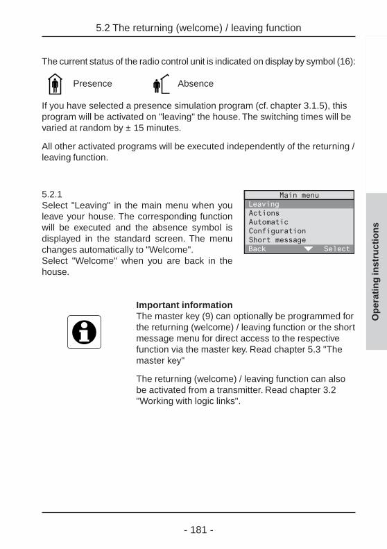
- 181 -
The current status of the radio control unit is indicated on display by symbol (16):
Presence Absence
If you have selected a presence simulation program (cf. chapter 3.1.5), thisprogram will be activated on "leaving" the house. The switching times will bevaried at random by ± 15 minutes.
All other activated programs will be executed independently of the returning /leaving function.
5.2.1Select "Leaving" in the main menu when youleave your house. The corresponding functionwill be executed and the absence symbol isdisplayed in the standard screen. The menuchanges automatically to "Welcome".Select "Welcome" when you are back in thehouse.
Important informationThe master key (9) can optionally be programmed forthe returning (welcome) / leaving function or the shortmessage menu for direct access to the respectivefunction via the master key. Read chapter 5.3 "Themaster key"
The returning (welcome) / leaving function can alsobe activated from a transmitter. Read chapter 3.2"Working with logic links".
Op
erat
ing
inst
ruct
ion
s
5.2 The returning (welcome) / leaving function

- 182 -
Op
erat
ing
inst
ruct
ion
s
5.3 The master key
5.3 The master key
The master key (9) can optionally be programmed for one of the followingfunctions:
- No functionThe master key has no function.
- Short messageThe master key can be used to recall, write, change or delete a shortmessage. Read chapter 5.1 "Using short messages".
- Returning / leaving functionThe master key can be used to activate alternately the returning(welcome) / leaving function. Read chapter 5.2 "The returning / leavingfunction".
5.3.1To program the master key for a specificfunction, select "Configuration -System –Master key" in the menu."Back" returns to the next higher menu level.
5.3.2The possible functions for the master key aredisplayed. Move the bar to the function youwant to activate directly with the master keyand confirm your selection with "Select". Thefunction is now programmed and the screenreturns to the next higher level.

- 183 -
5.4 Special functions (delay, action)
If required, each radio control receiver can be programmed for the specialfunctions ‘delay’ and ‘action’. Three different settings are available:
Delay: 0 min; action: <none>
This is the preset configuration for each receiver, i.e. the respective receiverdoes not execute any special functions. When the returning function(‘welcome’ function) is called up, the value stored before leaving will berestored.
Delay: 0 min; action: defined
On activation of the returning function, the respective receiver immediatelyexecutes the function defined here.
Example: switching actuator; delay: 0 min; action: on On activation of the returning function, the switching actuator switches on.
Delay: > 0 min; action: defined
On reception of a programmed radio telegram from the radio control unit,the respective receiver executes first the corresponding action. After thedefined delay, the receiver executes the action defined here under specialfunctions.
Example: switching actuator; delay: 1 min; action: offIn addition, a logic link is defined for this switching actuator, in which a radiocontrol detector as initiator is to switch on the radio control receiver.
On reception of a detector telegram via the radio control unit, theswitching actuator is first switched on and then off again after 1 min.
On activation of the returning function, the value stored before leaving isrestored. After the delay of 1 min has elapsed, the actuator switches off.
Op
erat
ing
inst
ruct
ion
s
5.4 Special functions (delay, action)

- 184 -
Op
erat
ing
inst
ruct
ion
s
5.4 Special functions (delay, action)
Technical information 1-channel flush-mountedswitching actuator
If a 1-channel flush-mounted switching actuatorwhich is not at least version R2 is used in your radiocontrol system (see device rating plate), note thefollowing special behaviour:
On activation of the leaving function or on storing of alight-scene via the radio control unit, this switchingactuator always saves the "Off" status.
In special function setting , this actuator wouldtherefore remain off on activation of the returningfunction.If you prefer the "On" state instead, it is recommendedto select special function setting ‚ with
delay = 0 min; action: onThe switching actuator will then always switch onwhen the returning function is activated.
If light-scenes are stored with this actuator via theradio control unit, the device will always save the"Off" state. To save the "On" state for the light-scene,the scene must be stored with another radio controltransmitter (e.g. radio control hand transmitter).

- 185 -
Setting of delays and actions for receivers
To set the delay time and the action for a specific receiver, select"Configuration - Components - Overview" from the menu.
5.4.1Select the room where the desired receiver islocated (in this case: Study)."Back" returns to the previous screen.
5.4.2Select "receiver" in the menu."Back" returns to the previous screen.
5.4.3The list of receiver types is displayed.Receivers above the line "---" are receivertypes actually existing in the selected room.Below the line, all other receiver types arelisted.Select the receiver type above the line forwhich the delay and the action are to be set(in this case: Switching actuator)."Back" returns to the previous screen.
5.4.4A list with the switching actuators existing inthe selected room is displayed. Select theswitching actuator for which you want to setthe delay and the action (in this case: Desk)."Back" returns to the previous screen.
Op
erat
ing
inst
ruct
ion
s
5.4 Special functions (delay, action)

- 186 -
Op
erat
ing
inst
ruct
ion
s
5.4 Special functions (delay, action)
5.4.5Select here "Special functions"."Back" returns to the previous screen.
5.4.6Select "Delay" to set a delay between 0 and240 min (interval 1 min).Select "Action" to program an action into thereceiver."Back" stores the adjusted values.
Actions: further reading
The meaning of individual actions is explained in thepresent operating instructions in chapter 3.1.1"Setting up time-controlled programs" on page 115.

- 187 -
Op
erat
ing
inst
ruct
ion
s
6.0 Project saving
6.0 Project saving
The radio control unit manual is supplied with a radio control unit Mastercardfor saving project data.
All customer-specific project data can be saved on this card and, if needed,also be reloaded into the unit.
The radio control unit Mastercard is detected automatically by the radiocontrol unit when the standard screen is displayed. The card is inserted withthe micro-chip ahead into the chip-card reader (4) as shown in fig. 6.a.
Important informationIf the inserted radio control unit Mastercard is not thecard issued with your radio control unit, a correspondinginformation will be displayed. After confirming the info,it is never-theless possible to load project data fromand to save project data back onto this card.
Glass front coverTo remove the front cover, cf. chapter 1.4 "Removal ofthe front cover" of the fitting and start-up instructions.
Fig. 6.a: Inserting the radio control unit Mastercard

- 188 -
Op
erat
ing
inst
ruct
ion
s
6.1 Saving the project
6.1 Saving the project
To save the current project data, insert the radio control unit Mastercard intothe chip-card reader as shown in chapter 6.0.
6.1.1After identification of the card, the radiocontrol unit automatically displays the mastercard menu. Select "Save project"."Back" returns to the standard screen.
6.1.2If you want to save the current project data,confirm with "Yes".Important:Any existing project data on the radio controlunit Mastercard will be overwritten.
After successful saving of the data, the radio control unit returns to the menuand the radio control unit Mastercard can be removed.

- 189 -
Op
erat
ing
inst
ruct
ion
s
6.2 Loading the project
6.2 Loading the project
To load project data from an radio control unit Mastercard, insert the cardinto the chip-card reader as shown in fig. 6.0.
6.2.1After identification of the card, the radiocontrol unit automatically displays the mastercard menu. Select "Load project"."Back" returns to the standard screen.
6.2.2If you want to load the project data from theinserted card, confirm with "Yes".Important:Any existing project data in the radio controlunit will be overwritten.
After successful loading of the data, the radio control unit returns to themenu and the radio control unit Mastercard can be removed.

- 190 -
Op
erat
ing
inst
ruct
ion
s
7.0 Transmitter diagnosis
7.0 Transmitter diagnosis
Your radio control unit offers the possibility to display the room, name andbattery condition of programmed transmitters for diagnosis purposes.
7.0.1Select "Configuration - Components –Transmitter test" in the menu."Back" returns to the next higher menu level.
7.0.2Send a radio telegram from a programmedtransmitter. "Back" returns to the previousscreen.
7.0.3If the transmitter is a programmed one, theradio control unit displays the following datafor the control transmitter:
- room- transmitter type- transmitter name- battery condition
No battery status message will be displayed, if the batteries are still in goodcondition.

- 191 -
Manual
Annex

- 192 -
A) Troubleshooting and answers to problems
Overview
a) Plug symbol (20) flashing
b) Battery symbol (21) flashing or on
c) Keypad does not react
d) PIN number of configuration menu access lock forgotten.
e) A program does not work.
f) On recalling of light-scenes or of the returning function, a 1-channelflush-mounted switching actuator remains always off although a differentbrightness should be in memory.
g) After actuation of All-Off or triggering of the leaving function, one or moreactuators switch on again.
h) A logic link shows no reaction.
i) Logic links do not respond to a battery-operated transmitter (e.g. hand orwall transmitter)
j) Delays occurring between actuation of transmitter and actual execution ofaction in actuator (receiver).
k) Display too dark or too bright.
Annex A – Troubleshooting and answers to problems
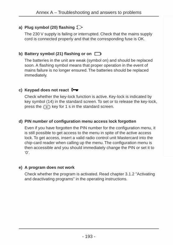
- 193 -
a) Plug symbol (20) flashing
The 230 V supply is failing or interrupted. Check that the mains supplycord is connected properly and that the corresponding fuse is OK.
b) Battery symbol (21) flashing or on
The batteries in the unit are weak (symbol on) and should be replacedsoon. A flashing symbol means that proper operation in the event ofmains failure is no longer ensured. The batteries should be replacedimmediately.
c) Keypad does not react
Check whether the key-lock function is active. Key-lock is indicated bykey symbol (14) in the standard screen. To set or to release the key-lock,press the key for 1 s in the standard screen.
d) PIN number of configuration menu access lock forgotten
Even if you have forgotten the PIN number for the configuration menu, itis still possible to get access to the menu in spite of the active accesslock. To get access, insert a valid radio control unit Mastercard into thechip-card reader when calling up the menu. The configuration menu isthen accessible and you should immediately change the PIN or set it to‘0’.
e) A program does not work
Check whether the program is activated. Read chapter 3.1.2 "Activatingand deactivating programs" in the operating instructions.
Annex A – Troubleshooting and answers to problems
- 194 -
f) On recalling of light-scenes or of the returning function, a 1-channelflush-mounted switching actuator remains always off although adifferent brightness should be in memory.
Light-scene: Note the info concerning the 1-channel flush-mountedswitching actuator in chapter 3.3.1 "Storing and changing of light-scenes"in the operating instructions.
Returning (welcome) function: Note the info concerning the 1-channelflush-mounted switching actuator in chapter 5.2 "The returning / leavingfunction" in the operating instructions.
g) After actuation of All-Off or triggering of the leaving function, one ormore actuators switch on again.
If this is not desired (e.g. as emergency lighting) check the specialfunctions assigned to the actuators concerned. Read chapter 5.4."Special functions" in the operating instructions. If a delay is preset forthese actuators and if an action (e.g switching on) is defined, set delay to"0 min" and action to "<no function>".
h) A logic link shows no reaction
Check whether the logic link is activated. Read chapter 3.2.2 "Activatingand deactivating logic links" in the operating instructions. Check also thatthe defined time (day and time of day) are OK and that a predefinedcondition, if any, is fulfilled.
i) Logic links do not respond to a battery-operated transmitter (e.g.hand or wall transmitter)
Check out first the solutions offered under (h). Then, check thetransmitter batteries for condition by performing a transmitter diagnosis.Read chapter 7.0 "Transmitter diagnosis" in the operating instructions.
Annex A – Troubleshooting and answers to problems

- 195 -
j) Delays occurring between actuation of transmitter and actualexecution of action in actuator (receiver).
If an external repeater is used to improve the transmitting range, thisdevice must have been programmed into the radio control unit. Repeatersmay cause time delays.If no external repeater is installed, no such device must be programmedin the unit. Read also chapters 2.2 and 4.0 "Repeater functions" in theoperating instructions.
k) Display too dark or too bright
Readjust the contrast in the "Configuration - System - Contrast" menu.The contrast can also be adjusted by pressing the key together withfunction key 2 for more contrast and together with function key 3 for lesscontrast.
Fig. A1: Function keys 2 & 3
Annex A – Troubleshooting and answers to problems

- 196 -
B) Serial numbers and versions
The serial numbers and version info for your radio control unit can be foundin the menu under "Configuration - System - Information".
Note the numbers here to have them available in case the unit needsservicing:
1: * _ _ _ _ _ _ _ _ *2: * _ _ _ _ _ _ _ _ *3: * _ _ _ _ *
4: * _ _ _ _ _ _ _ _ *5: * _ _ _ _ _ _ _ _ *6: * _ _ _ _ _ _ _ _ *7: * _ _ _ _ _ _ _ _ *
ImportantThe field marked in grey _ contains the software versionnumber
Annex B - Serial numbers and versions
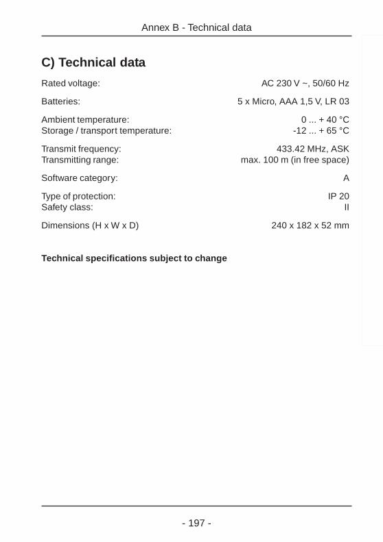
- 197 -
C) Technical dataRated voltage: AC 230 V ~, 50/60 Hz
Batteries: 5 x Micro, AAA 1,5 V, LR 03
Ambient temperature: 0 ... + 40 °CStorage / transport temperature: -12 ... + 65 °C
Transmit frequency: 433.42 MHz, ASKTransmitting range: max. 100 m (in free space)
Software category: A
Type of protection: IP 20Safety class: II
Dimensions (H x W x D) 240 x 182 x 52 mm
Technical specifications subject to change
Annex B - Technical data
- 198 -
Annex D - Acceptance of guarantee
D) Acceptance of guarantee
We accept the guarantee in accordance with the corresponding legal provisions.
Please return the unit postage paid to our central service departmentgiving a brief description of the fault:
GiraGiersiepen GmbH & Co. KGService CenterDahlienstraße 12D-42461 RadevormwaldFederal Republic of Germany
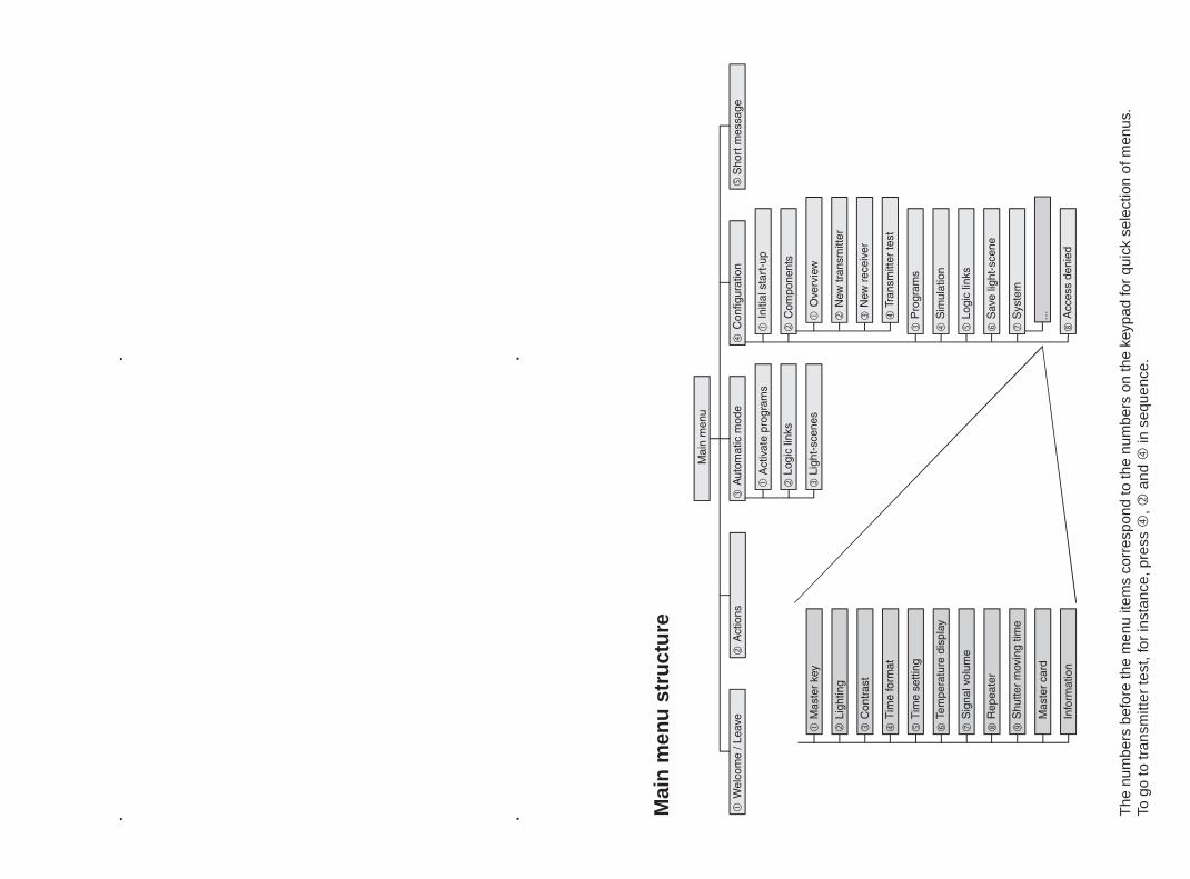
. .
. . The
num
bers
bef
ore
the
men
u ite
ms
corr
espo
nd to
the
num
bers
on
the
keyp
ad fo
r qu
ick
sele
ctio
n of
men
us.
To g
o to
tran
smitt
er te
st, f
or in
stan
ce, p
ress
,
and
in
seq
uenc
e.
Mai
n m
enu
str
uct
ure
GIRAGiersiepen GmbH & Co. KG
Postfach 12 20D-42461 Radevormwald
Telefon: 0 21 95 / 602-0Telefax: 0 21 95 / 602 339Internet: www.gira.deE-mail: [email protected]

Supplement to Manual on Heating Control
Radio Controller 0358 18

2
This manual provides you with information on the latest "Heating control" software update for the radio controller. This latest change is not yet contained in the radio controller manual. You can request the revised manual from us from November 2005 or download it on the Internet at www.gira.de.

3
Heating Control The motor valve drives of your heating can be controlled both without and with room temperature sensors via the radio controller. In both cases the radio controller specifies temperature setpoints via time-controlled programs, links and in the manual mode for the motor valve drives. The respective last value sent applies. • Time-controlled programs
Temperature setpoints are sent to selected motor valve drives at specified times and evaluated there.
• Links With radio transmitters (e.g. hand-held transmitters, wall transmitters etc.) you can have the radio controller send temperature setpoints to the motor valve drives.
• Manual operation In the "Action menu" of the Radio controllers you can set or change temperature setpoints for your motor valve drives. In addition, the Party function or frost protection can also be selected.
The related actual temperature values are delivered by the motor valve drives, the room temperature sensors or the radio controller depending on the setting. This setting is located in the configuration menu (see "Special functions for motor valve drives“).
The following additional functions offer you convenience for heating control with the radio controller:
Holiday When the Holiday function is activated, a temperature setpoint you have defined is permanently set for a certain period (1 to 31 days), i.e. it is not overwritten by any other setpoint (e.g. from a time-controlled program). The Holiday function ends after the set period ends or through manual deactivation. The first day of the Holiday function is the day on which the Holiday function is activated. The Holiday function can refer to your entire house (central function), to certain rooms or to individual motor valve drives. You can activate and deactivate the Holiday function in the "Automatic menu".

4
Frost Protection When the Frost Protection function is activated, a temperature setpoint you have defined (default: 15 °C) is permanently set, i.e. it is not overwritten by any other setpoint (e.g. from a time-controlled program). The Frost Protection function must be ended by switching it off manually. It is practical if you are away from home for more than 31 days. Otherwise it is advisable to use the Holiday function. The Frost Protection function can be activated or deactivated in the "Actions menu", via "Links" or via "Programs".
Party When the Party function is activated, a temperature setpoint you have defined is permanently set for a certain time (1, 2, 3 or 4 hrs.), i.e. it is not overwritten by any other setpoint (e.g. from a time-controlled program). The Party function ends after the set time ends or through manual switch-off. You can activate or deactivate the Party function in the "Actions menu" or via "Links".
Assigning a Motor Valve Drive When assigning a motor valve drive, the radio controller expects a confirmation from the valve drive. These are cyclically sent by the valve drive as soon as it is in the programming mode.
Special Functions for Motor Valve Drives You can define the following special functions for your motor valve drives in the menu "Configuration - Components - Overview - <Room> - Receiver - Valve Drive". • Heating circuit distributor • Basic temperature • Departing temperature • Actual value sensor • Status

5
Heating circuit distributor If the motor valve drive is operated on a heating circuit distributor (e.g. floor heating), you should set it here. As a result, the temperature setpoint and actual value are updated every 3 minutes instead of every 10 minutes.
Basic temperature Set a basic temperature here between 5 °C and 30 °C (increment: 0.5 K). If you do not specify a value, then the basic temperature is set to 18 °C. The related motor valve drive sets this basic temperature if no other temperature setpoint is available to it (e.g. following initialisation).
Departing temperature Set the temperature here which is to be set when the Departing function is activated. A temperature range from 5 °C to 30 °C with increments of 0.5 K is available. If you do not wish a change to be made when departing, select "No action" here.
Actual value sensor So that a motor valve drive can carry out control with a temperature setpoint, it requires an actual temperature value. The motor valve drive provides itself with this. However, it can also be provided by a room temperature sensor or the radio controller as an alternative. Select a corresponding actual value sensor from the list specified here. The setting "Sensor valve drive" means that the respective motor valve drive uses its own actual temperature value for control.
Status In the Status screen you can view the current temperature setpoint and actual value of the respective motor valve drive for information purposes. If a "–" is shown for the actual value instead of a temperature, then "Sensor valve drive" has been selected as the actual value sensor. In this case the motor valve drive uses its own actual temperature valve for control. In addition, the status of the Party, Frost Protection and Holiday functions, as well as of the heating circuit distributor is also shown in the status screen. Here the symbols have the following meaning: = Function is activated – = Function is deactivated

6
Creating Time-Controlled Programs With a motor valve drive as a receiver (link), the following actions can be selected independently of the selected triggering device: Setpoint, Change setpoint, Party and Frost Protection.
Presence (only with: All) • Departing
With motor valve drives, the temperature defined for "Departing" is set or no action is carried out (menu: Configuration - Components - Overview - Receiver - <Valve drive list> - Special Functions)
• Arriving With motor valve drives, the temperature setpoint applicable at this point in time (e.g. time-controlled program) is restored.
Setpoint Setting temperature The valve drive can be set here to a certain setpoint temperature between 5 °C and 30 °C in 0.5 °C increments. First the current setpoint temperature is shown on the screen. Set the new setpoint temperature directly with the numeric keypad or with "▲" and "▼" and then confirm your entry with "OK". "Back" returns to the previous screen. Note: If one of the functions Frost Protection, Party or Holiday is active, then this must first be deactivated.
Changing Setpoint Increasing/decreasing The temperature setpoint can be increased or decreased here between 0.5 K and 5 K (0.5 K increments). The increase or decrease applies temporarily until the next new temperature setpoint is received (e.g. by a program). Entering 0 sets the temperature to the original temperature setpoint again.
Party Function When the Party function is activated, a temperature setpoint you have defined is permanently set for a certain time (1, 2, 3 or 4 hrs.), i.e. it is not overwritten by any other setpoint (e.g. from a time-controlled program). The Party function ends after the set time ends or through manual switch-off.
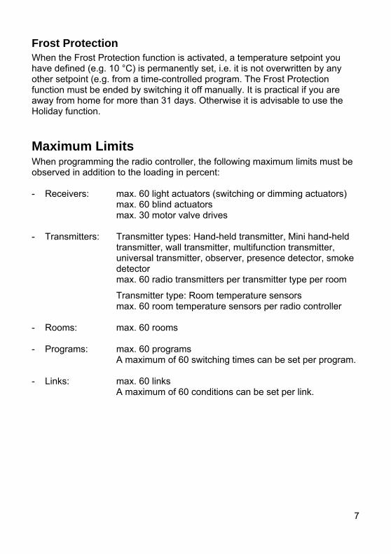
7
Frost Protection When the Frost Protection function is activated, a temperature setpoint you have defined (e.g. 10 °C) is permanently set, i.e. it is not overwritten by any other setpoint (e.g. from a time-controlled program. The Frost Protection function must be ended by switching it off manually. It is practical if you are away from home for more than 31 days. Otherwise it is advisable to use the Holiday function.
Maximum Limits When programming the radio controller, the following maximum limits must be observed in addition to the loading in percent: - Receivers: max. 60 light actuators (switching or dimming actuators)
max. 60 blind actuators max. 30 motor valve drives
- Transmitters: Transmitter types: Hand-held transmitter, Mini hand-held
transmitter, wall transmitter, multifunction transmitter, universal transmitter, observer, presence detector, smoke detector max. 60 radio transmitters per transmitter type per room
Transmitter type: Room temperature sensors max. 60 room temperature sensors per radio controller - Rooms: max. 60 rooms - Programs: max. 60 programs
A maximum of 60 switching times can be set per program. - Links: max. 60 links
A maximum of 60 conditions can be set per link.
8
Gira Giersiepen GmbH & Co. KG Electrical Installation Systems Industriegebiet Mermbach Dahlienstrasse 42477 Radevormwald Postfach 1220 42461 Radevormwald Tel.: +49 (0) 21 95- 602-0 Fax: +49 (0) 21 95- 602-339 www.gira.de [email protected]
09.2
005
Related Documents