1 jector Accelerator Readiness Review, 10/31/06 nrik Loos Beam Losses During LCLS Injector Phase-1 Operation Scope of phase 1 operation Operating modes Operating plan for phase 1 Beam power and losses during nominal operation Maximum credible beam Summary of maximum credible beam in injector and linac

Injector Accelerator Readiness Review, 10/31/06 Henrik Loos 1 Beam Losses During LCLS Injector Phase-1 Operation Scope of phase 1 operation Operating modes.
Dec 27, 2015
Welcome message from author
This document is posted to help you gain knowledge. Please leave a comment to let me know what you think about it! Share it to your friends and learn new things together.
Transcript

1Injector Accelerator Readiness Review, 10/31/06Henrik Loos
Beam Losses DuringLCLS Injector Phase-1 Operation
Scope of phase 1 operationOperating modesOperating plan for phase 1Beam power and losses during nominal operationMaximum credible beam Summary of maximum credible beam in injector and linac
2Injector Accelerator Readiness Review, 10/31/06Henrik Loos
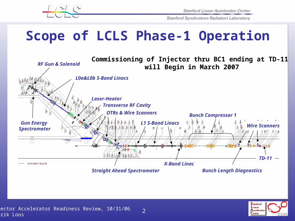
RF Gun & Solenoid
Gun Energy Spectrometer
L0a&L0b S-Band Linacs
Laser-Heater
OTRs & Wire Scanners
Straight Ahead Spectrometer
Transverse RF Cavity
L1 S-Band Linacs
Bunch Compressor 1
Wire Scanners
Bunch Length DiagnosticsX-Band Linac
Commissioning of Injector thru BC1 ending at TD-11 will Begin in March 2007
TD-11
Scope of LCLS Phase-1 Operation

3Injector Accelerator Readiness Review, 10/31/06Henrik Loos
1. Beam operation from the LCLS injector gun to dump SDMP during LINAC operation, which is located in Sector 21-1. Magnets BX01/BX02 will be locked off.
2. Beam operation from the LCLS injector gun to dump TD11, which is located in sector 21-3. Dump TD11 will be disabled “in”.
The following modes of operation for phase-1 of LCLS injector commissioning have been approved:
Modes for LCLS Injector Phase-1 Operation

4Injector Accelerator Readiness Review, 10/31/06Henrik Loos
http://www-ssrl.slac.stanford.edu/lcls/internals/commissioning/documents/commissioning-dates-2006-2007.ppthttp://www-ssrl.slac.stanford.edu/lcls/internals/commissioning/documents/commissioning-dates-2006-2007.ppt
Dec 22:Dec 22: PPS CertifiedPPS Certified
Dec 20-Jan 1:Dec 20-Jan 1: HolidaysHolidays
Jan 2:Jan 2: VVS’s switched on for PEP-II (RF power available)VVS’s switched on for PEP-II (RF power available)
Jan 15:Jan 15: L0a, L0b, L1 RF processing beginsL0a, L0b, L1 RF processing begins
Feb. 1:Feb. 1: X-band RF X-band RF processing beginsprocessing begins
Feb 20:Feb 20: GTL beamline installation completeGTL beamline installation complete
Mar 6:Mar 6: Virtual cathode fully characterized (ready to install gun)Virtual cathode fully characterized (ready to install gun)
Mar 7:Mar 7: RF gun installation begins – laser rate to 30 HzRF gun installation begins – laser rate to 30 Hz
Mar 16:Mar 16: First laser UV-light on cathode!First laser UV-light on cathode!
Mar 17:Mar 17: Electrons in GTL and gun-spectrometerElectrons in GTL and gun-spectrometer
Apr 9:Apr 9: Beam through L0a, L0b and down to 135-MeV spectrometerBeam through L0a, L0b and down to 135-MeV spectrometer
Apr 24:Apr 24: Beam into main linac (to TD11 dump)Beam into main linac (to TD11 dump)
~July:~July: Take beam down full linac (to BSY SL2 stopper)Take beam down full linac (to BSY SL2 stopper)
LCLS Injector Commissioning Dates (2006 - 2007)

5Injector Accelerator Readiness Review, 10/31/06Henrik Loos
LCLS Phase 1 Operation
Date LCLS Program Test Beam Program
Administrative Controls
Jan 4 –Jan 29
RF Processing, no beam
Linac set-up and SABER
BX01/02 locked off
Jan 30 –Feb 12
RF Processing, no beam
ESA for ILC BX01/02 locked off
Feb 12 –Mar 25
Beam to 7 MeV Gun Spectrometer
OFF TD11 disabled IN
Mar 26 –Apr 8
Beam to 7 MeV Gun Spectrometer
SABER BX01/02 locked off
Apr 9 –Jul 9
Beam to TD11 (and 52SL2 ?)
OFF TD11 disabled IN
Jul 9 –Jul 22
Off or Beam to 135 MeV Inj. Spect.
ESA for ILC and test beams
BX01/02 locked off
Jul 23 –Aug 20
Beam to TD11 (and 52SL2 ?)
OFF TD11 disabled IN
Aug 20 –Aug 31
Off or Beam to 135 MeV Inj. Spect.
SABER BX01/02 locked off

6Injector Accelerator Readiness Review, 10/31/06Henrik Loos
Nominal operation120 Hz., 1 nC, 6.2 MeV0.744 watts Stopped in
Either FC01/YAG01, FCG1 or YAG02
Nominal operation120 Hz., 1 nC, 6.2 MeV0.744 watts Stopped in
Either FC01/YAG01, FCG1 or YAG02
Penetration to Drive Laser Rm.
Nominal beam loss locations in the gun-to-linac region, not including dark current
L0-a
RF Gun
Nominal Beam: Losses in the Gun-to-Linac (GTL) Region

7Injector Accelerator Readiness Review, 10/31/06Henrik Loos
Gun: 6 MeV, 0.7 W
TD11: 250 MeV, 30 W
135 MeV, 16 W
SDMP: 135 MeV, 16 W
250 MeV, 30 W
Nominal Beam Power Along Injector

8Injector Accelerator Readiness Review, 10/31/06Henrik Loos
3-nC initial gun dark current based on worst-case GTF operations
where dark current is generated
where dark current is observed
dark current energy (MeV)
dark current charge/ pulse
(nC)
current at 120 Hz (A)
average beam power (W)
in gun after gun 6.2 3 0.36 2.2 in L0-a in L0-b
after L0-a after L0-b
56 73
0.16 0.16
0.019 0.019
1.1 1.4
in L0-a after L0-b 130 0.16 0.019 2.5
Dark current energy sources and powerestimates for the LCLS injector at 120 Hz

9Injector Accelerator Readiness Review, 10/31/06Henrik Loos
Estimated average beam power loss and location along the LCLS in nominal and special tune-up conditions. Power levels set in bold type occur in normal operating conditions. Non-bold entries are special configurations as described in the “note” column.
Table Notes:aa. This loss occurs only when this Faraday cup is inserted (6 MeV, 120 Hz).a. This loss occurs only with beam on the gun spectrometer (6 MeV, 120 Hz).b. This loss occurs only with beam on the injector spectrometer (135 MeV, 120 Hz).c. This is a normal loss due primarily to dark current from gun and injector.d. This loss occurs only with beam on this tune-up dump (120 Hz).
Component Description Area Linac z [m]
LCLS z [m]†
Energy [GeV]
Power [W]
note
FC01 Gun Faraday cup gun 2018.42 - 0.006 3 aa FCG1 Spec. Faraday cup gun 2018.47 - 0.006 1.15 aa GSDMP gun-spec. dump gun 2018.44 - 0.006 1.15 a SDMP inj.-spec. dump SAB 2036.08 - 0.135 16 b BX01 DL1 bend chamber DL1 2032.07 - 0.135 2 c L1X X-band struc. iris BC1 2044.76 - 0.260 0.5 c CE11 energy collimator BC1 2049.34 - 0.250 < 0.1 c TD11 tune-up dump BC1 2058.57 - 0.250 30 d
Nominal and Tune-up Beam Losses from Gun through BC1 ending at TD11

10Injector Accelerator Readiness Review, 10/31/06Henrik Loos
Explosive electron emission occurs from the photocathode if the drive laser intensity exceeds the threshold for plasma production. This emission persists until it has depleted the gun of all its stored energy.
Source in a RF Photocathode Gun is Explosive Electron Emission
Maximum Credible Beam

11Injector Accelerator Readiness Review, 10/31/06Henrik Loos
The quads between L0-a and L0-b transport 64 MeV electrons so will over-focus MCB electrons causing lost in the L0-b structure. Max power deposited in L0-b is assumed to be the full beam power of 2.2 kW.
The macro pulse 1.2 A is accelerated by L0-a, with beam loading it will have energies between 21 to 76 MeV, with 48 MeV average energy. Average beam power at L0-a exit: (48 MeV)(0.38 C)(120 Hz) 2.2 kW.
The maximum stored energy in the gun is 10 J at 140 MV/m. Beam loading gives 4 MeV energy, therefore the max charge/pulse is (10 J)/(4 MeV) = 2.5microC, at 120 Hz, current is 0.30mA. Studies show 85% lost in GTL, average loss is (4 MeV)(0.30mA) (85%) 1.0 kW.
Quads OFF: this beam could be accelerated by L0-b, with range of 56 to 160 MeV, for the max 62 MW RF power and beam loading. The average energy is (160 MeV+56 MeV)/2 110 MeV, average power is (110 MeV)(0.38 C)(120 Hz) 5.0 kW after L0-b.
DL1 bend off: 5.0 kW lost in and after the spectrometer dipole.
Max energy is 160 MeV and DL1 energy acceptance is 5%, the highest energy with max transmission is (1 - 5%)(160 MeV) 150 MeV. Worst case MCB to main linac is 150 MeV with average power of (13%)(0.38 C)(150 MeV)(120 Hz) 0.9 kW.
Acceleration to 250MeV, MCB ~ 6A*250MeV=1.5kW after L1
MCB in TD11 ~ 1.5 kW
Estimate for Maximum Credible Beam

12Injector Accelerator Readiness Review, 10/31/06Henrik Loos
LCLS GRD 1.1-001 at: http://www-ssrl.slac.stanford.edu/lcls/prd/1.1-001-r0.pdf.
Location Average Energy (GeV)
Charge per pulse
(C)
Current at 120 Hz
(A)
Beam Power (kW)
Gun exit 0.004 2.5 300 1.2
Beam loss in gun region 0.004 2.1 260 1.0
Beam on FCG1 Faraday cup in gun spectrometer 0.004 0.38 45 0.18
L0-a exit 0.048 0.38 45 2.2
Max. beam loss in L0-b 0.048 0.38 45 2.2
L0-b exit 0.110 0.38 45 5.0
Beam loss at straight ahead spectrometer 0.110 0.38 45 5.0
Beam transported to main linac (nom. DL1 setting) 0.110 0.050 6.0 0.6
X-iris 0.250 0.050 6.0 1.5
Bunch Compressor BC1 0.250 0.050 6.0 1.5
Dump TD11 0.250 0.050 6.0 1.5
Summary of Maximum Credible Beam PowerAlong the Injector and into the Linac
Related Documents


![DEVICE OPERATION OF POLYMER LIGHT-EMITTING … Bound... · DEVICE OPERATION OF POLYMER LIGHT-EMITTING DIODES ... and Ca asan electron injector. ... in disordered materials [13] ...](https://static.cupdf.com/doc/110x72/5a9e077d7f8b9a39338be6c2/device-operation-of-polymer-light-emitting-bounddevice-operation-of-polymer.jpg)


