1-5012-4-EN Injection oilers, micro pumps for minimal quantity metering Delivery rates Metering pumps deliver lubricants in a mea- sured amount. These piston pumps are for small delivery rates from 3 to 30 mm 3 . The lubricant’s delivery rate is partially adjustable. Main features • Optimal metering of every lube point re- gardless of line lengths and cross sections • Lubricant supplied from one central res- ervoir, a standalone reservoir, and also by a central pressurized oil line in the case of injection oilers • Metering elements can be actuated indi- vidually or in groups • Splash lubrication through high oil accel- eration (injection oiler) • Fast sequence of pulses: up to 120 pulses per minute (injection oiler) • Space saving design • Ecofriendly: no oil in the exhaust air Possible applications • Air oiling (assembly tools) • Greasing of small parts (assembly support) • Chain lubrication Injection oiler, 3-port type Micro pump Injection oiler, 1-port type

Welcome message from author
This document is posted to help you gain knowledge. Please leave a comment to let me know what you think about it! Share it to your friends and learn new things together.
Transcript

1-5012-4-EN
Injection oilers, micro pumpsfor minimal quantity metering
Delivery rates
Metering pumps deliver lubricants in a mea-
sured amount. These piston pumps are for
small delivery rates from 3 to 30 mm3. The
lubricant’s delivery rate is partially adjustable.
Main features
• Optimal metering of every lube point re-
gardless of line lengths and cross sections
• Lubricant supplied from one central res-
ervoir, a standalone reservoir, and also by
a central pressurized oil line in the case of
injection oilers
• Metering elements can be actuated indi-
vidually or in groups
• Splash lubrication through high oil accel-
eration (injection oiler)
• Fast sequence of pulses:
up to 120 pulses per minute
(injection oiler)
• Space saving design
• Ecofriendly: no oil in the exhaust air
Possible applications
• Air oiling (assembly tools)
• Greasing of small parts (assembly support)
• Chain lubrication
Injection oiler, 3-port type Micro pumpInjection oiler, 1-port type

Injection Oilers, Micro Pumps
2 1-5012-4-EN
S
P T1
P3
P2
P1
Z P
Oiling during production of camshafts
Adjustment of delivery rate
All injection oilers are set for maximum de-
livery volume at the plant. The delivery rate
can be reduced in increments by turning the
setting sleeve counterclockwise.
Max. delivery rate/stroke 30 mm3
1 full turn to the left: 25 mm3
2 full turns to the left: 20 mm3
3 full turns to the left: 15 mm3
4 full turns to the left: 10 mm3
5 full turns to the left: 5 mm3
over 6 full turns to the left: 3 mm3
The setting sleeve can be set by hand.
It engages 4 times per revolution (which
can be heard and felt) so that intermediate
settings are also possible. The maximum de-
livery rate is set again by turning the setting
sleeve clockwise to the stop.
The first start-up should take place at the
maximum delivery rate.
Sectional view of injection oiler
P
Z Compressed air pulse
P Lubricant
Injection Oilers, Micro Pumps
31-5012-4-EN
45
32
14 40
50
10534 30
21
21
56
8
28.5
72
P1
P2
P3
Z1
Z3
Z2
SZ
P
G1/8G1/8 M6
x0.7
5
(M8
x1)
1)
ø6.72)
ø6.5
SZ
ø6.72)
G1/8
–
+
–
+
–
+
–
+
1
2
3
5)4)3)
5)4)3)
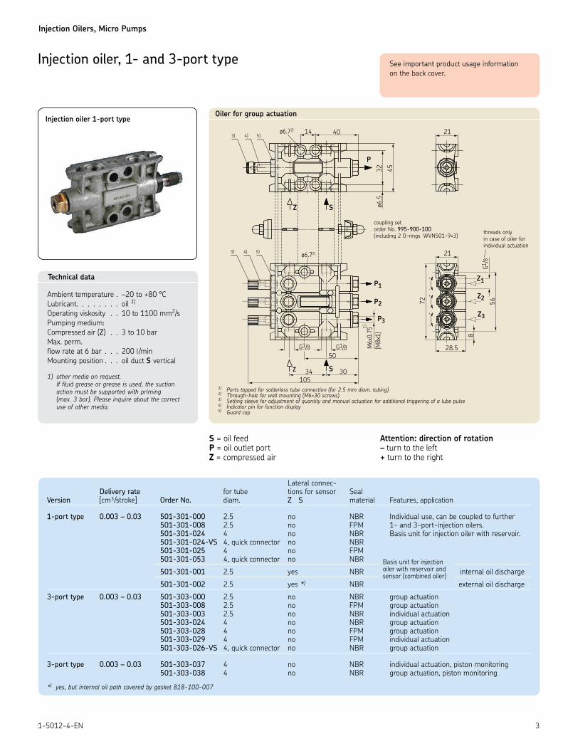
Oiler for group actuation
Injection oiler, 1- and 3-port type
S = oil feed P = oil outlet port Z = compressed air
Attention: direction of rotation – turn to the left + turn to the right
Technical data
Ambient temperature . –20 to +80 °CLubricant. . . . . . . . oil 1)
Operating viskosity . . 10 to 1100 mm2/sPumping medium:Compressed air (Z) . . 3 to 10 barMax. perm. flow rate at 6 bar . . . 200 l/min Mounting position . . . oil duct S vertical
1) other media on request. If fluid grease or grease is used, the suction action must be supported with priming (max. 3 bar). Please inquire about the correct use of other media.
threads only in case of oiler for individual actuation
coupling set order No. 995-900-100 (including 2 O-rings WVN501-9×3)
Lateral connec- Delivery rate for tube tions for sensor Seal Version [cm³/stroke] Order No. diam. Z S material Features, application
1-port type 0.003 – 0.03 501-301-000 2.5 no NBR Individual use, can be coupled to further 501-301-008 2.5 no FPM 1- and 3-port-injection oilers. 501-301-024 4 no NBR Basis unit for injection oiler with reservoir. 501-301-024-VS 4, quick connector no NBR 501-301-025 4 no FPM 501-301-053 4, quick connector no NBR
501-301-001 2.5 yes NBR internal oil discharge
501-301-002 2.5 yes *) NBR external oil discharge
3-port type 0.003 – 0.03 501-303-000 2.5 no NBR group actuation 501-303-008 2.5 no FPM group actuation 501-303-003 2.5 no NBR individual actuation 501-303-024 4 no NBR group actuation 501-303-028 4 no FPM group actuation 501-303-029 4 no FPM individual actuation 501-303-026-VS 4, quick connector no NBR group actuation
3-port type 0.003 – 0.03 501-303-037 4 no NBR individual actuation, piston monitoring 501-303-038 4 no NBR group actuation, piston monitoring
*) yes, but internal oil path covered by gasket 818-100-007
Basis unit for injection oiler with reservoir and sensor (combined oiler)
See important product usage information on the back cover.
1) Ports tapped for solderless tube connection (for 2.5 mm diam. tubing)2) Through-hole for wall mounting (M6×30 screws)3) Setting sleeve for adjustment of quantity and manual actuation for additional triggering of a lube pulse4) Indicator pin for function display5) Guard cap
Injection oiler 1-port type
Injection Oilers, Micro Pumps
4 1-5012-4-EN
G1/8 (4×)
LUFT
AIR
1)M
8×1OEL
OIL
P
32
M12
×1
LED
–
+
02135
66.3
(Öl/oil)(Luft/air)Z S
03444108
34
45
2)
3) 4) 5)
–+
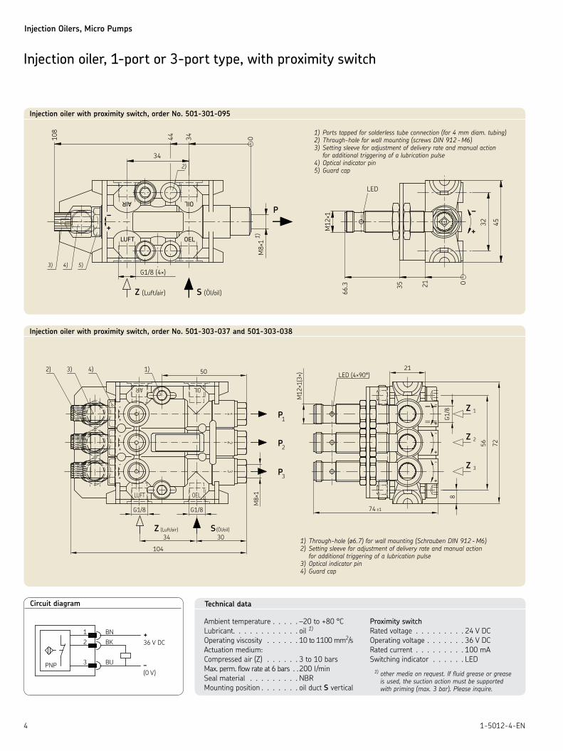
Injection oiler with proximity switch, order No. 501-301-095
1) Ports tapped for solderless tube connection (for 4 mm diam. tubing)2) Through-hole for wall mounting (screws DIN 912 - M6)3) Setting sleeve for adjustment of delivery rate and manual action for additional triggering of a lubrication pulse4) Optical indicator pin5) Guard cap
Injection oiler, 1-port or 3-port type, with proximity switch
+36 V DC
PNP 3
2
1
BU – (0 V)
BK
BN
Circuit diagram Technical data
Ambient temperature . . . . . –20 to +80 °CLubricant. . . . . . . . . . . . oil 1)
Operating viscosity . . . . . . 10 to 1100 mm2/sActuation medium:Compressed air (Z) . . . . . . 3 to 10 barsMax. perm. flow rate at 6 bars . . 200 l/min Seal material . . . . . . . . . NBR Mounting position . . . . . . . oil duct S vertical
Proximity switch
Rated voltage . . . . . . . . . 24 V DCOperating voltage . . . . . . . 36 V DCRated current . . . . . . . . . 100 mASwitching indicator . . . . . . LED
1) other media on request. If fluid grease or grease is used, the suction action must be supported with priming (max. 3 bar). Please inquire.
(Öl/oil)(Luft/air)Z S
+
-
Z 1
Z 2
Z 3
OELLUFT
-
-
32
+
-
AIR OIL
1
G1/8 G1/8
21
72
G1/8
74 ±1
M12
×1(3
×)+
-
+
-
56
8
3P
P2
1P
M8×
1
501)4)3)2)
3034
104
LED (4×90°)
+
+
1) Through-hole (ø6.7) for wall mounting (Schrauben DIN 912 - M6)2) Setting sleeve for adjustment of delivery rate and manual action for additional triggering of a lubrication pulse3) Optical indicator pin4) Guard cap
Injection oiler with proximity switch, order No. 501-303-037 and 501-303-038

Injection Oilers, Micro Pumps
51-5012-4-EN
Z
S
Z1
Z2
Z3
P
Example 2: Gravity oil layout with venting line (group and individual actuation combined)
ZSP
Example 1: Gravity oil layout (group actuation)
P
Z
S
Example 3: Configuration of a large system with ring line (group actuation)
to the lube points
to the lube points
air pulse for group actuation
air pulse for group actuation
priming pump
max. 3 bar
screw plug sealing ring
S = oil feedP = oil outlet portZ = compressed air port
to the lube points air pulse for
individual actuation
air pulse for group actuation
Both control types can be combined in any way desired.
Injection oiler, 1-port type
Z3
Z2
P3
P2
Z1 P
P1
Injection oiler, 3-port type, individual actuation
P3
P2
P1
Z P
Injection oiler, 3-port type, group actuation
Z1 Z3Z2
Air flow with individual actuation
Z Z
Air flow with group actuation

Injection Oilers, Micro Pumps
6 1-5012-4-EN
132.5
113.5
38.5
22.5
6.5
9
0
13
73
G 1/8
Z
P
M6
×0.7
51
)
105
1) Ports tapped for solderless tube connection (for 2.5 mm diam. tubing)
Injection oilers, 1- and 3-port type, with reservoir
Injection oiler, 1-port type, with reservoir
The injection oiler is combined with a reser-
voir of transparent material when used with
only a few lube points.
Applications
• tool lubrication
Further injection oilers can be hooked up.
The individual metering pumps can in turn
be actuated individually or in groups. If the
lubrication frequency has to be scaled down,
the injection oiler can be coupled with a
counting stage.
We recommend that a venting line be laid
for automatic venting of the oil-conducting
chambers and bores (cf. illus.).
Injection oilers with reservoir
Reservoir Reservoir Seal Order No. Version capacity [l] material material
501-301-011 NBR501-301-028 1-port type 0.25 PA6-3-T FPM501-301-029 NBR
501-303-011 3-port type 0.25 PA6-3-T NBR
Mounting position as shownSee page 3 for technical dataSee page 2 for adjustment of delivery rate
O-ring WVN501-9×3
O-ring WVN501-9×3
venting line
Injection oiler, 1-port type, with reservoir
Automatic venting when coupled
to further injection oilers

Injection Oilers, Micro Pumps
71-5012-4-EN
105
ø8.5
20
M12×1
ø100
WS
~ 21
0
G1/880
Z
1)M
8×1
P
Injection oiler, 1-port type, with reservoir
Reservoir Seal Order No. capacity [l] material
501-301-056 0.8 NBR
Mounting position as shownSee page 3 for technical dataSee page 2 for adjustment of delivery rate
The reservoir is equipped with a float switch
(WS) for minimum level.
The float switch opens with sinking level.
Circular plug connection M12×1
Max. load: 10 VA
0.25 A
240 V AC
P = oil outlet
Z = compressed air connection
1) Ports tapped for solderless tube connection (for 4 mm diam. tubing)
Injection oiler with reservoir, order No. 501-301-056

Injection Oilers, Micro Pumps
8 1-5012-4-EN
72
323
ø9 (4×)
ø120
P
100
82
M14×1.51)
105
G1/4
Grease reservoir
filler socket
grease level indicator
compressed air connection port for following piston
1) Ports tapped for solderless tube connection (for 8 mm diam. tubing)
Technical data
Order No. . . . . . . . . . . . . . . . . . . . . . . . . . . . . . . . . . . . . . . . . . . . . . . . . . . . . . . BF1.5
Compressed air for following piston . . . . . . . . . . . . . . . . . . . . . . . . . . . . . . . . . . max. 10 bar
Lubricant . . . . . . . . . . . . . . . . . . . . . . . . . . . . . . . . . . . . . . . . . . . . . . . . . . . . . . . grease up to . . . . . . . . . . . . . . . . . . . . . . . . . . . . . . . . . . . . . . . . . . . . . . . . . . . . . . . . . . . . . . . NLGI grade 2Reservoir capacity . . . . . . . . . . . . . . . . . . . . . . . . . . . . . . . . . . . . . . . . . . . . . . . . 1.5 kg Mounting position . . . . . . . . . . . . . . . . . . . . . . . . . . . . . . . . . . . . . . . . . . . . . . . . any
Grease reservoir, order No. BF1.5
Connection fittings
for M14×1.5: socket union 408-202 double tapered sleeve 408-001
for G1/4: washer 508-108 adaptor 406-054 for tube 6 mm diam. or 301-020 for tube 8 mm diam.
Grease reservoir 1,5 Liter
Injection Oilers, Micro Pumps
91-5012-4-EN
PV.PV.003
03
2× ø5.5
71
BA 10C
P2
P3
20.2
77.5
20.2
=20.2
52
(PVU.1643)
= 20.2
16.5
7.2 14
21.3
ø5.5
M4= =
max. 4 ports 20
A
B
C
stroke
12=
=
air port
20
2× G1/8
2× G1/4
outlet ports M10×1
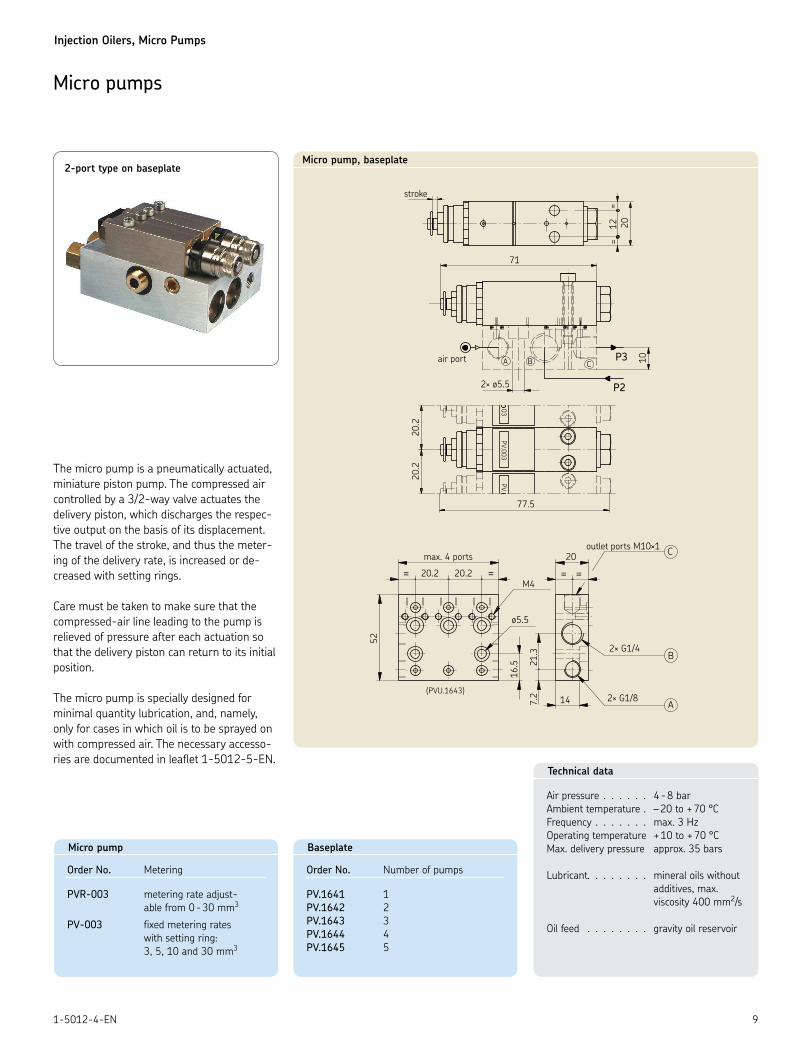
Micro pumps
2-port type on baseplate
The micro pump is a pneumatically actuated,
miniature piston pump. The compressed air
controlled by a 3/2-way valve actuates the
delivery piston, which discharges the respec-
tive output on the basis of its displacement.
The travel of the stroke, and thus the meter-
ing of the delivery rate, is increased or de-
creased with setting rings.
Care must be taken to make sure that the
compressed-air line leading to the pump is
relieved of pressure after each actuation so
that the delivery piston can return to its initial
position.
The micro pump is specially designed for
minimal quantity lubrication, and, namely,
only for cases in which oil is to be sprayed on
with compressed air. The necessary accesso-
ries are documented in leaflet 1-5012-5-EN. Technical data
Air pressure . . . . . . 4 - 8 bar Ambient temperature . – 20 to + 70 °CFrequency . . . . . . . max. 3 HzOperating temperature + 10 to + 70 °CMax. delivery pressure approx. 35 bars
Lubricant. . . . . . . . mineral oils without additives, max. viscosity 400 mm2/s
Oil feed . . . . . . . . gravity oil reservoir
Micro pump, baseplate
Baseplate
Order No. Number of pumps
PV.1641 1 PV.1642 2 PV.1643 3 PV.1644 4 PV.1645 5
Micro pump
Order No. Metering
PVR-003 metering rate adjust- able from 0 - 30 mm3
PV-003 fixed metering rates with setting ring: 3, 5, 10 and 30 mm3


This brochure was presented by:
Order No. 1-5012-4-ENSubject to change without notice! (09/2017)
Important product usage informationAll products from SKF may be used only for their intended purpose as described in this brochure and in any instructions. If operating instructions are supplied with the products, they must be read and followed.Not all lubricants are suitable for use in centralized lubrication systems. SKF does offer an inspection service to test customer supplied lubricant to determine if it can be used in a centralized system. SKF lubrication systems or their components are not approved for use with gases, liquefied gases, pressurized gases in solution and fluids with a vapor pressure exceeding normal atmospheric pressure (1013 mbars) by more than 0.5 bar at their maximum permissible temperature.Hazardous materials of any kind, especially the materials classified as hazard-ous by European Community Directive EC 67/548/EEC, Article 2, Par. 2, may only be used to fill SKF centralized lubrication systems and components and delivered and/or distributed with the same after consulting with and receiving written approval from SKF.
SKF Lubrication Systems Germany GmbH
Motzener Strasse 35/37 · 12277 Berlin · Germany
PF 970444 · 12704 Berlin · Germany
Tel. +49 (0)30 72002-0 · Fax +49 (0)30 72002-111
www.skf.com/lubrication
® SKF is a registered trademark of the SKF Group.
© SKF Group 2017The contents of this publication are the copyright of the publisher and may not be reproduced (even extracts) unless prior written permission is granted. Every care has been taken to ensure the accuracy of the information contained in this publication but no liability can be accepted for any loss or damage whether direct, indirect or consequential arising out of the use of the information contained herein.
Further brochures1-4003-EN Electromagnetic pump PE 1-9201-EN Transport of Lubricants in Centralized Lubrication Systems
Related Documents