OS137 SERIES Miniature Non-Contact Infrared Temperature Sensor/Transmitter CAUTION! – This product is not intended for medical use or use on humans e-mail: [email protected] For latest product manuals: omegamanual.info Shop online at omega.com ® User’s Guide

Welcome message from author
This document is posted to help you gain knowledge. Please leave a comment to let me know what you think about it! Share it to your friends and learn new things together.
Transcript

OS137 SERIESMiniature Non-Contact Infrared Temperature Sensor/Transmitter
CAUTION! – This product�is not intended for medical�use or use on humans
e-mail: [email protected] latest product manuals:
omegamanual.info
Shop online atomega.com®
User’s Guide

Servicing North America:U.S.A.: Omega Engineering, Inc., One Omega Drive, P.O. Box 4047ISO 9001 Certified Stamford, CT 06907-0047 USA
Toll Free: 1-800-826-6342 TEL: (203) 359-1660FAX: (203) 359-7700 e-mail: [email protected]
Canada: 976 BergarLaval (Quebec), H7L 5A1 CanadaToll-Free: 1-800-826-6342 TEL: (514) 856-6928FAX: (514) 856-6886 e-mail: [email protected]
For immediate technical or application assistance:U.S.A. and Canada: Sales Service: 1-800-826-6342/1-800-TC-OMEGA®
Customer Service: 1-800-622-2378/1-800-622-BEST®
Engineering Service: 1-800-872-9436/1-800-USA-WHEN®
Mexico/ En Español: 001 (203) 359-7803 FAX: 001 (203) 359-7807Latin America: [email protected] e-mail: [email protected]
Servicing Europe:Benelux: Managed by the United Kingdom Office
Toll-Free: 0800 099 3344 TEL: +31 20 347 21 21FAX: +31 20 643 46 43 e-mail: [email protected]
Czech Republic: Frystatska 184733 01 Karviná, Czech RepublicToll-Free: 0800-1-66342 TEL: +420-59-6311899FAX: +420-59-6311114 e-mail: [email protected]
France: Managed by the United Kingdom OfficeToll-Free: 0800 466 342 TEL: +33 (0) 161 37 29 00FAX: +33 (0) 130 57 54 27 e-mail: [email protected]
Germany/ Austria: Daimlerstrasse 26D-75392 Deckenpfronn, GermanyToll-Free: 0800 6397678 TEL: +49 (0) 7056 9398-0FAX: +49 (0) 7056 9398-29 e-mail: [email protected]
United Kingdom: OMEGA Engineering Ltd.ISO 9001 Certified One Omega Drive, River Bend Technology Centre, Northbank
Irlam, Manchester M44 5BD United KingdomToll-Free: 0800-488-488 TEL: +44 (0) 161 777-6611FAX: +44 (0) 161 777-6622 e-mail: [email protected]
OMEGAnet® Online Service Internet e-mailomega.com [email protected]
It is the policy of OMEGA Engineering, Inc. to comply with all worldwide safety and EMC/EMIregulations that apply. OMEGA is constantly pursuing certification of its products to the European New Approach Directives. OMEGA will add the mark to every appropriate device upon certification.The information contained in this document is believed to be correct, but OMEGA accepts no liability for any errors it contains, and reserves the right to alter specifications without notice.WARNING: These products are not designed for use in, and should not be used for, human applications.
i
OS137 Series Miniature Non-Contact Infrared Temperature Sensor/Transmitter
Table of Contents
Section Page
Caution & Safety Information ........................................................................ iiiSafety Warnings and IEC Symbols ................................................................. iii
Section 1 Introduction ..................................................................................... 1
Section 2 Installation ........................................................................................ 12.1 Unpacking .................................................................................. 12.2 Electrical Connection ................................................................ 2
Section 3 Operation ......................................................................................... 33.1 Measuring Temperature ........................................................... 33.2 Ambient Temperature ............................................................... 43.3 Atmospheric Quality ................................................................ 43.4 Alarm Setting ............................................................................. 6
Section 4 Laser Sight Accessory ..................................................................... 74.1 Warnings and Caution .............................................................. 74.2 Operating the Laser Sight Accessory ..................................... 7
Section 5 Specifications ................................................................................... 95.1 General ........................................................................................ 95.2 Laser Sight Accessory ............................................................. 10
Section 6 Emissivity Tables ........................................................................... 11
OS137 Series Miniature Non-Contact Infrared Temperature Sensor/Transmitter
ii
Table of Figures
Figure Description Page
2-1 General Wiring Diagram ................................................................ 2
2-2 Alarm Output Wiring Diagram .................................................... 2
3-1 Optical Field of View ...................................................................... 3
3-2 Location of Emissivity & Alarm Adjust and Alarm Switch ......... 3
3-3 Mounting Bracket, OS137-MB ....................................................... 4
3-4 Air Purge Collar, OS137-AP ........................................................... 4
3-5 Stainless Steel Housing .................................................................. 5
3-6 Water/Air Cool Jacket, OS137-WC .............................................. 5
4-1 Laser Sighting Accessory, OS137-LS ............................................. 8
4-2 Laser Warning Label........................................................................ 8
OS137 Series Miniature Non-Contact Infrared Temperature Sensor/Transmitter
iii
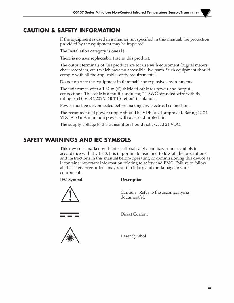
CAUTION & SAFETY INFORMATIONIf the equipment is used in a manner not specified in this manual, the protectionprovided by the equipment may be impaired.
The Installation category is one (1).
There is no user replaceable fuse in this product.
The output terminals of this product are for use with equipment (digital meters,chart recorders, etc.) which have no accessible live parts. Such equipment shouldcomply with all the applicable safety requirements.
Do not operate the equipment in flammable or explosive environments.
The unit comes with a 1.82 m (6') shielded cable for power and outputconnections. The cable is a multi-conductor, 24 AWG stranded wire with therating of 600 VDC, 205ºC (401°F) Teflon® insulation.
Power must be disconnected before making any electrical connections.
The recommended power supply should be VDE or UL approved. Rating:12-24VDC @ 50 mA mininum power with overload protection.
The supply voltage to the transmitter should not exceed 24 VDC.
SAFETY WARNINGS AND IEC SYMBOLSThis device is marked with international safety and hazardous symbols inaccordance with IEC1010. It is important to read and follow all the precautionsand instructions in this manual before operating or commissioning this device asit contains important information relating to safety and EMC. Failure to followall the safety precautions may result in injury and/or damage to yourequipment.
IEC Symbol Description
Caution - Refer to the accompanyingdocument(s).
Direct Current
Laser Symbol
1
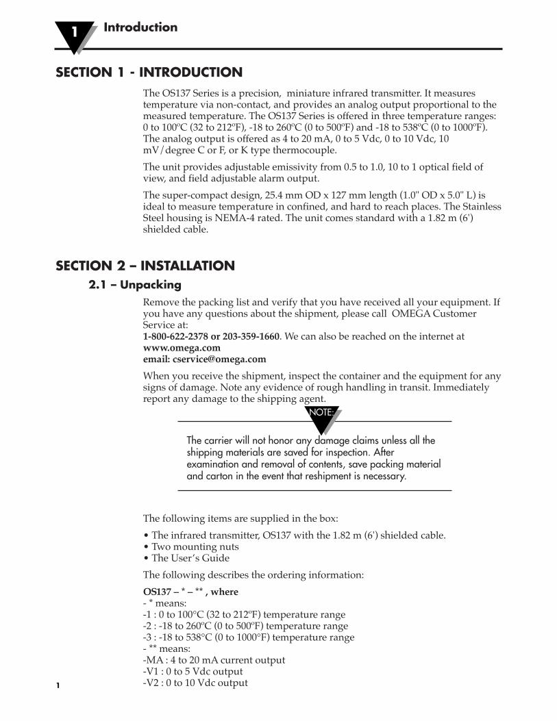
SECTION 1 - INTRODUCTIONThe OS137 Series is a precision, miniature infrared transmitter. It measurestemperature via non-contact, and provides an analog output proportional to themeasured temperature. The OS137 Series is offered in three temperature ranges:0 to 100ºC (32 to 212ºF), -18 to 260ºC (0 to 500ºF) and -18 to 538ºC (0 to 1000ºF).The analog output is offered as 4 to 20 mA, 0 to 5 Vdc, 0 to 10 Vdc, 10mV/degree C or F, or K type thermocouple.
The unit provides adjustable emissivity from 0.5 to 1.0, 10 to 1 optical field ofview, and field adjustable alarm output.
The super-compact design, 25.4 mm OD x 127 mm length (1.0" OD x 5.0" L) isideal to measure temperature in confined, and hard to reach places. The StainlessSteel housing is NEMA-4 rated. The unit comes standard with a 1.82 m (6')shielded cable.
SECTION 2 – INSTALLATION2.1 – Unpacking
Remove the packing list and verify that you have received all your equipment. Ifyou have any questions about the shipment, please call OMEGA CustomerService at:1-800-622-2378 or 203-359-1660. We can also be reached on the internet atwww.omega.comemail: [email protected]
When you receive the shipment, inspect the container and the equipment for anysigns of damage. Note any evidence of rough handling in transit. Immediatelyreport any damage to the shipping agent.
The carrier will not honor any damage claims unless all theshipping materials are saved for inspection. Afterexamination and removal of contents, save packing materialand carton in the event that reshipment is necessary.
The following items are supplied in the box:
• The infrared transmitter, OS137 with the 1.82 m (6') shielded cable.• Two mounting nuts• The User’s Guide
The following describes the ordering information:
OS137 – * – ** , where- * means:-1 : 0 to 100°C (32 to 212ºF) temperature range-2 : -18 to 260ºC (0 to 500ºF) temperature range-3 : -18 to 538°C (0 to 1000°F) temperature range- ** means:-MA : 4 to 20 mA current output-V1 : 0 to 5 Vdc output-V2 : 0 to 10 Vdc output
Introduction1
NOTE:
2
2
-K : K type thermocouple output-MVC : 10 mV/ºC output-MVF : 10 mV/ºF outputFor longer power/output cable, add suffix “xxFT” to the model part number.
The following table lists the optional accessories:
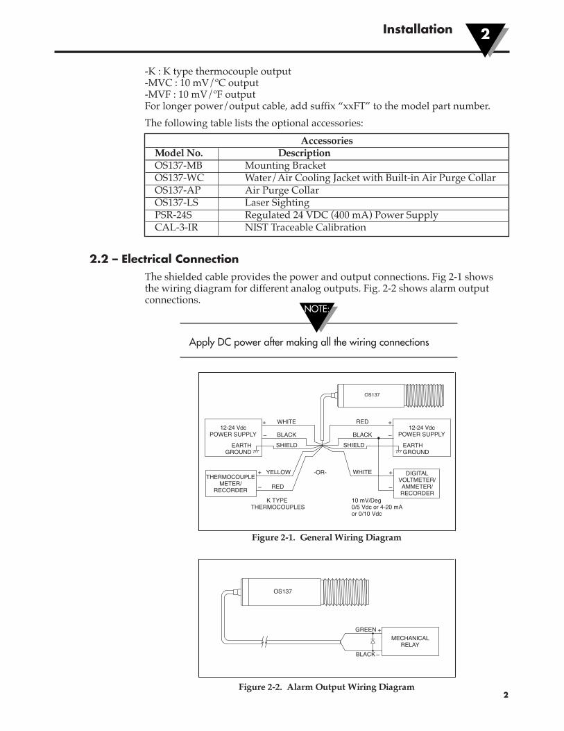
2.2 – Electrical ConnectionThe shielded cable provides the power and output connections. Fig 2-1 showsthe wiring diagram for different analog outputs. Fig. 2-2 shows alarm outputconnections.
Apply DC power after making all the wiring connections
Figure 2-1. General Wiring Diagram
Figure 2-2. Alarm Output Wiring Diagram
AccessoriesModel No. DescriptionOS137-MB Mounting BracketOS137-WC Water/Air Cooling Jacket with Built-in Air Purge CollarOS137-AP Air Purge CollarOS137-LS Laser SightingPSR-24S Regulated 24 VDC (400 mA) Power SupplyCAL-3-IR NIST Traceable Calibration
Installation
RED
WHITE
12-24 VdcPOWER SUPPLY
-OR-
10 mV/Deg0/5 Vdc or 4-20 mAor 0/10 Vdc
EARTHGROUND
DIGITALVOLTMETER/
AMMETER/RECORDER
BLACKSHIELD
+
+
–
–
YELLOWTHERMOCOUPLE
METER/RECORDER RED
K TYPE THERMOCOUPLES
+
–
OS137
WHITE12-24 Vdc
POWER SUPPLY
EARTHGROUND
BLACKSHIELD
+
–
NOTE:
OS137
+
–
MECHANICALRELAY
BLACK
GREEN
3
Operation3
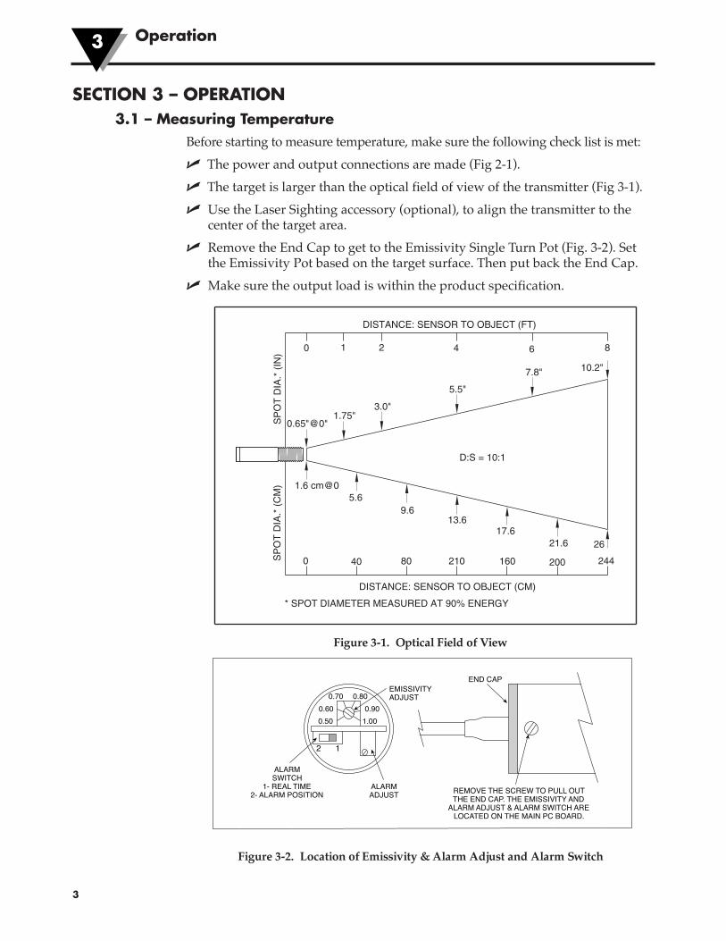
SECTION 3 – OPERATION3.1 – Measuring Temperature
Before starting to measure temperature, make sure the following check list is met:
� The power and output connections are made (Fig 2-1).
� The target is larger than the optical field of view of the transmitter (Fig 3-1).
� Use the Laser Sighting accessory (optional), to align the transmitter to thecenter of the target area.
� Remove the End Cap to get to the Emissivity Single Turn Pot (Fig. 3-2). Setthe Emissivity Pot based on the target surface. Then put back the End Cap.
� Make sure the output load is within the product specification.
Figure 3-1. Optical Field of View
Figure 3-2. Location of Emissivity & Alarm Adjust and Alarm Switch
SP
OT
DIA
.* (
CM
)S
PO
T D
IA.*
(IN
)
DISTANCE: SENSOR TO OBJECT (FT)
D:S = 10:1
1.6 cm@0
0 40
5.6
80
9.6
210
13.6
160
17.6
200
21.6
244
26
0.65"@0"
3.0"1.75"
5.5"
7.8" 10.2"
864210
DISTANCE: SENSOR TO OBJECT (CM)
* SPOT DIAMETER MEASURED AT 90% ENERGY
ALARM SWITCH
1- REAL TIME 2- ALARM POSITION
ALARM ADJUST
EMISSIVITY ADJUST
REMOVE THE SCREW TO PULL OUT THE END CAP. THE EMISSIVITY AND
ALARM ADJUST & ALARM SWITCH ARE LOCATED ON THE MAIN PC BOARD.
END CAP
12
1.00
0.70 0.60 0.90
0.80
0.50
Operation 3
4
3.2 – Ambient TemperatureThe transmitter can operate in an ambient temperature of 0 to 70°C (32 to 158°F)without any water cool jacket. It can operate from 0 to 200°C (32 to 392°F) withthe water cool jacket accessory, OS137-WC (Fig 3-6 & 3-7). It can operate up to110°C (230°F) with air cooling.
There is a warm up period of 1 to 2 minutes after power up. After the warm upperiod, temperature measurement can be made.
When the ambient temperature around the transmitter changes abruptly, the sensor headgoes through a thermal shock. It takes a certain amount of time for the sensor head to getstabilized to the new ambient temperature. For example, it takes about 30 minutes for thetransmitter to stabilize from the 25°C to 50°C (77°F to 122°F) ambient temperature.
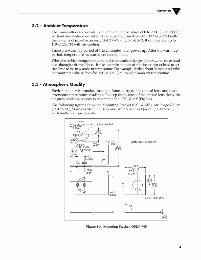
3.3 - Atmospheric QualityEnvironments with smoke, dust, and fumes dirty up the optical lens, and causeerroneous temperature readings. To keep the surface of the optical lens clean, theair purge collar accessory is recommended, OS137-AP (Fig 3-4).
The following figures show the Mounting Bracket (OS137-MB), Air Purge Collar(OS137-AP), Stainless Steel Housing and Water/Air Cool Jacket (OS137-WC),with built-in air purge collar.
Figure 3-3. Mounting Bracket, OS137-MB
DIMENSIONS mm (in)
57.2(2.25)
12.7(0.50)
95.3(3.75)
90
90
17.4(0.687)
19.8(0.78)
3.2(1/8)
3.2(1/8)
17.4(0.686)
INSERTOS137 HEAD
INTO THE HOLE
98.8(3.89)
96.5(3.80)
53.3(2.10)
25.4(1.0)
50.8(2.0)
25.9 (1.020) DIA.
4.3 (0.170) DIA.
4.3(0.170)
15.2(0.6)
32.5(1.28)
28.6(1.125)
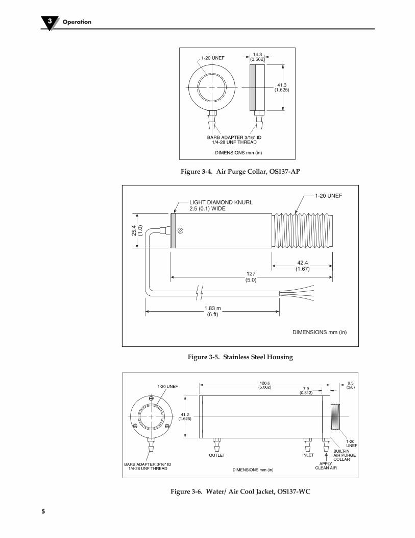
Figure 3-4. Air Purge Collar, OS137-AP
Figure 3-5. Stainless Steel Housing
Figure 3-6. Water/ Air Cool Jacket, OS137-WC
Operation3
5
LIGHT DIAMOND KNURL2.5 (0.1) WIDE
DIMENSIONS mm (in)
1-20 UNEF
127(5.0)
1.83 m(6 ft)
42.4(1.67)
25.4
(1.0
)
DIMENSIONS mm (in)
128.6(5.062) 7.9
(0.312)
41.2(1.625)
1-20 UNEF9.5
(3/8)
1-20UNEF
BUILT-INAIR PURGECOLLAR
APPLYCLEAN AIR
INLETOUTLET
BARB ADAPTER 3/16" ID1/4-28 UNF THREAD
DIMENSIONS mm (in)
BARB ADAPTER 3/16" ID1/4-28 UNF THREAD
1-20 UNEF14.3
(0.562)
41.3(1.625)
3.4 Alarm SettingThe unit provides 0-100% alarm setpoint adjustment. Here is an exampleof an alarm setting:
• An OS137-3-MA (4/20 mA output), the alarm is to be set at 204°C(400°F) temperature.
• Connect the alarm output as shown in Fig. 2-2.
• Remove the End Cap to get to the Alarm Switch and the Alarm Adjust (Fig. 3-2).
• Set the Slide Switch on the main board to the Alarm position (2).
• Measure the analog output, and adjust the Alarm Potentiometer untilthe output reads 10.4 mA which is 40% (204°C, 400°F) of thetemperature range -18 to 538°C, (0 to 1000°F)
40 x (20-4)[10.4mA = 100
+ 4]
• Set the Alarm Slide Switch back to the Real Time position (1).
• If the temperature reading is below the alarm setpoint, the AlarmOutput stays low, otherwise it goes high (Alarm Condition).
• The Alarm Output can drive an external mechanical relay.
Operation 3
6
SECTION 4 - LASER SIGHT ACCESSORY4.1 – Warnings and Caution
You may receive harmful laser radiation exposure if you donot adhere to the warnings listed below:
• USE OF CONTROLS OR ADJUSTMENTS OR PERFORMANCE OFPROCEDURES OTHER THAN THOSE SPECIFIED IN THIS GUIDE MAYRESULT IN HAZARDOUS RADIATION EXPOSURE.
• DO NOT LOOK AT THE LASER BEAM COMING OUT OF THE LENS ORVIEW IT DIRECTLY WITH OPTICAL INSTRUMENTS – EYE DAMAGE CANRESULT.
• USE EXTREME CAUTION WHEN OPERATING THE LASER SIGHTACCESSORY.
• NEVER POINT THE LASER ACCESSORY AT A PERSON.
• KEEP THE LASER SIGHT ACCESSORY OUT OF REACH OF ALLCHILDREN.
Do not attempt to open the laser sight accessory. There are nouser serviceable parts inside.
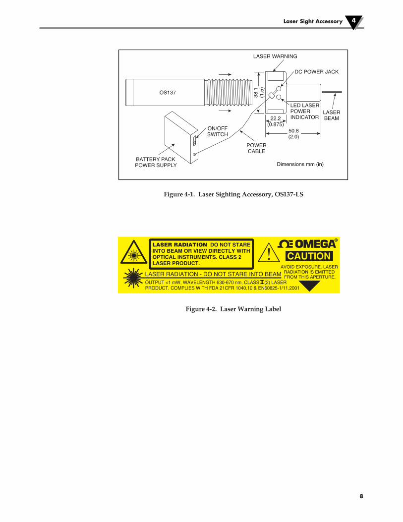
4.2 – Operating the Laser Sight AccessoryThe laser sight accessory screws onto the front of the transmitter sensor head.This accessory is only used for alignment of the transmitter head to the targetarea. After the alignment process, the accessory has to be removed from the frontof the transmitter head before temperature measurement is made.
The laser sight accessory is powered from a small, compact battery pack(included with the accessory). Connect the battery pack to the accessory usingthe cable provided. Aim at the target, and turn on the battery power using theslide switch on the battery pack. Adjust the sensor head position so that the laserbeam points to the center of the target area. Turn off the battery pack, andremove the laser sighting accessory from the sensor head (Fig 4-1).
CAUTION:
WARNING:
Laser Sight Accessory4
7
8
Figure 4-1. Laser Sighting Accessory, OS137-LS
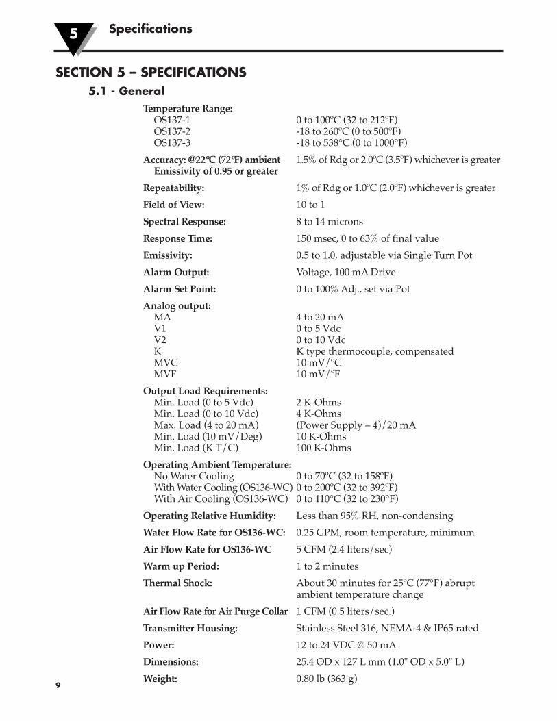
Figure 4-2. Laser Warning Label
LASER WARNING LABEL
DC POWER JACK
LED LASERPOWER INDICATOR
LASERBEAM22.2
(0.875)50.8(2.0)
38.1
(1.5
)
POWERCABLE
ON/OFFSWITCH
BATTERY PACKPOWER SUPPLY
OS137
Dimensions mm (in)
OUTPUT <1 mW, WAVELENGTH 630-670 nm, CLASS II (2) LASER PRODUCT. COMPLIES WITH FDA 21CFR 1040.10 & EN60825-1/11.2001
LASER RADIATION - DO NOT STARE INTO BEAM
LASER RADIATION DO NOT STARE INTO BEAM OR VIEW DIRECTLY WITH OPTICAL INSTRUMENTS. CLASS 2 LASER PRODUCT.
®
CAUTIONAVOID EXPOSURE. LASER
RADIATION IS EMITTED FROM THIS APERTURE.
Laser Sight Accessory 4
9
SECTION 5 – SPECIFICATIONS5.1 - General
Temperature Range:OS137-1 0 to 100ºC (32 to 212ºF)OS137-2 -18 to 260ºC (0 to 500ºF)OS137-3 -18 to 538°C (0 to 1000°F)
Accuracy: @22ºC (72ºF) ambient 1.5% of Rdg or 2.0ºC (3.5ºF) whichever is greaterEmissivity of 0.95 or greater
Repeatability: 1% of Rdg or 1.0ºC (2.0ºF) whichever is greater
Field of View: 10 to 1
Spectral Response: 8 to 14 microns
Response Time: 150 msec, 0 to 63% of final value
Emissivity: 0.5 to 1.0, adjustable via Single Turn Pot
Alarm Output: Voltage, 100 mA Drive
Alarm Set Point: 0 to 100% Adj., set via Pot
Analog output:MA 4 to 20 mAV1 0 to 5 VdcV2 0 to 10 VdcK K type thermocouple, compensatedMVC 10 mV/ºCMVF 10 mV/ºF
Output Load Requirements:Min. Load (0 to 5 Vdc) 2 K-OhmsMin. Load (0 to 10 Vdc) 4 K-OhmsMax. Load (4 to 20 mA) (Power Supply – 4)/20 mAMin. Load (10 mV/Deg) 10 K-OhmsMin. Load (K T/C) 100 K-Ohms
Operating Ambient Temperature:No Water Cooling 0 to 70ºC (32 to 158ºF)With Water Cooling (OS136-WC) 0 to 200ºC (32 to 392ºF)With Air Cooling (OS136-WC) 0 to 110°C (32 to 230°F)
Operating Relative Humidity: Less than 95% RH, non-condensing
Water Flow Rate for OS136-WC: 0.25 GPM, room temperature, minimum
Air Flow Rate for OS136-WC 5 CFM (2.4 liters/sec)
Warm up Period: 1 to 2 minutes
Thermal Shock: About 30 minutes for 25ºC (77°F) abruptambient temperature change
Air Flow Rate for Air Purge Collar 1 CFM (0.5 liters/sec.)
Transmitter Housing: Stainless Steel 316, NEMA-4 & IP65 rated
Power: 12 to 24 VDC @ 50 mA
Dimensions: 25.4 OD x 127 L mm (1.0" OD x 5.0" L)
Weight: 0.80 lb (363 g)
Specifications5
10
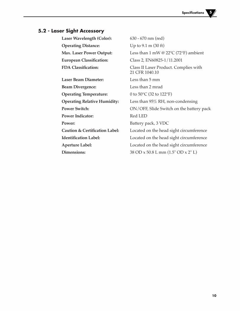
5.2 - Laser Sight AccessoryLaser Wavelength (Color): 630 - 670 nm (red)
Operating Distance: Up to 9.1 m (30 ft)
Max. Laser Power Output: Less than 1 mW @ 22ºC (72°F) ambient
European Classification: Class 2, EN60825-1/11.2001
FDA Classification: Class II Laser Product. Complies with21 CFR 1040.10
Laser Beam Diameter: Less than 5 mm
Beam Divergence: Less than 2 mrad
Operating Temperature: 0 to 50°C (32 to 122°F)
Operating Relative Humidity: Less than 95% RH, non-condensing
Power Switch: ON/OFF, Slide Switch on the battery pack
Power Indicator: Red LED
Power: Battery pack, 3 VDC
Caution & Certification Label: Located on the head sight circumference
Identification Label: Located on the head sight circumference
Aperture Label: Located on the head sight circumference
Dimensions: 38 OD x 50.8 L mm (1.5" OD x 2" L)
Specifications 5
Emissivity Table6
11
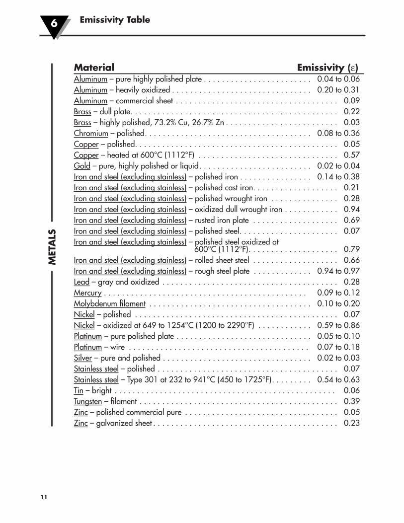
Material Emissivity (ε)Aluminum – pure highly polished plate . . . . . . . . . . . . . . . . . . . . . . . . 0.04 to 0.06Aluminum – heavily oxidized . . . . . . . . . . . . . . . . . . . . . . . . . . . . . . . 0.20 to 0.31Aluminum – commercial sheet . . . . . . . . . . . . . . . . . . . . . . . . . . . . . . . . . . . . 0.09Brass – dull plate. . . . . . . . . . . . . . . . . . . . . . . . . . . . . . . . . . . . . . . . . . . . . . 0.22Brass – highly polished, 73.2% Cu, 26.7% Zn . . . . . . . . . . . . . . . . . . . . . . . . . 0.03Chromium – polished. . . . . . . . . . . . . . . . . . . . . . . . . . . . . . . . . . . . . 0.08 to 0.36Copper – polished. . . . . . . . . . . . . . . . . . . . . . . . . . . . . . . . . . . . . . . . . . . . . 0.05Copper – heated at 600°C (1112°F) . . . . . . . . . . . . . . . . . . . . . . . . . . . . . . . 0.57Gold – pure, highly polished or liquid. . . . . . . . . . . . . . . . . . . . . . . . . 0.02 to 0.04Iron and steel (excluding stainless) – polished iron . . . . . . . . . . . . . . . . 0.14 to 0.38Iron and steel (excluding stainless) – polished cast iron. . . . . . . . . . . . . . . . . . . 0.21Iron and steel (excluding stainless) – polished wrought iron . . . . . . . . . . . . . . . 0.28Iron and steel (excluding stainless) – oxidized dull wrought iron . . . . . . . . . . . . 0.94Iron and steel (excluding stainless) – rusted iron plate . . . . . . . . . . . . . . . . . . . 0.69Iron and steel (excluding stainless) – polished steel. . . . . . . . . . . . . . . . . . . . . . 0.07Iron and steel (excluding stainless) – polished steel oxidized at
600°C (1112°F). . . . . . . . . . . . . . . . . . . . 0.79Iron and steel (excluding stainless) – rolled sheet steel . . . . . . . . . . . . . . . . . . . 0.66Iron and steel (excluding stainless) – rough steel plate . . . . . . . . . . . . . 0.94 to 0.97Lead – gray and oxidized . . . . . . . . . . . . . . . . . . . . . . . . . . . . . . . . . . . . . . . 0.28Mercury . . . . . . . . . . . . . . . . . . . . . . . . . . . . . . . . . . . . . . . . . . . . . 0.09 to 0.12Molybdenum filament . . . . . . . . . . . . . . . . . . . . . . . . . . . . . . . . . . . . 0.10 to 0.20Nickel – polished . . . . . . . . . . . . . . . . . . . . . . . . . . . . . . . . . . . . . . . . . . . . . 0.07Nickel – oxidized at 649 to 1254°C (1200 to 2290°F) . . . . . . . . . . . . 0.59 to 0.86Platinum – pure polished plate . . . . . . . . . . . . . . . . . . . . . . . . . . . . . . 0.05 to 0.10Platinum – wire . . . . . . . . . . . . . . . . . . . . . . . . . . . . . . . . . . . . . . . . 0.07 to 0.18Silver – pure and polished . . . . . . . . . . . . . . . . . . . . . . . . . . . . . . . . . 0.02 to 0.03Stainless steel – polished . . . . . . . . . . . . . . . . . . . . . . . . . . . . . . . . . . . . . . . . 0.07Stainless steel – Type 301 at 232 to 941°C (450 to 1725°F). . . . . . . . . 0.54 to 0.63Tin – bright . . . . . . . . . . . . . . . . . . . . . . . . . . . . . . . . . . . . . . . . . . . . . . . . . 0.06Tungsten – filament . . . . . . . . . . . . . . . . . . . . . . . . . . . . . . . . . . . . . . . . . . . . 0.39Zinc – polished commercial pure . . . . . . . . . . . . . . . . . . . . . . . . . . . . . . . . . . 0.05Zinc – galvanized sheet . . . . . . . . . . . . . . . . . . . . . . . . . . . . . . . . . . . . . . . . . 0.23
MET
ALS
Emissivity Table 6
12
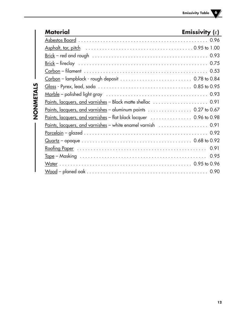
Material Emissivity (ε)Asbestos Board . . . . . . . . . . . . . . . . . . . . . . . . . . . . . . . . . . . . . . . . . . . . . . . 0.96
Asphalt, tar, pitch . . . . . . . . . . . . . . . . . . . . . . . . . . . . . . . . . . . . . . . 0.95 to 1.00
Brick – red and rough . . . . . . . . . . . . . . . . . . . . . . . . . . . . . . . . . . . . . . . . . . 0.93
Brick – fireclay . . . . . . . . . . . . . . . . . . . . . . . . . . . . . . . . . . . . . . . . . . . . . . . 0.75
Carbon – filament . . . . . . . . . . . . . . . . . . . . . . . . . . . . . . . . . . . . . . . . . . . . . 0.53
Carbon – lampblack - rough deposit . . . . . . . . . . . . . . . . . . . . . . . . . . 0.78 to 0.84
Glass - Pyrex, lead, soda . . . . . . . . . . . . . . . . . . . . . . . . . . . . . . . . . . 0.85 to 0.95
Marble – polished light gray . . . . . . . . . . . . . . . . . . . . . . . . . . . . . . . . . . . . . 0.93
Paints, lacquers, and varnishes – Black matte shellac . . . . . . . . . . . . . . . . . . . . 0.91
Paints, lacquers, and varnishes – aluminum paints . . . . . . . . . . . . . . . . 0.27 to 0.67
Paints, lacquers, and varnishes – flat black lacquer . . . . . . . . . . . . . . . 0.96 to 0.98
Paints, lacquers, and varnishes – white enamel varnish . . . . . . . . . . . . . . . . . . 0.91
Porcelain – glazed . . . . . . . . . . . . . . . . . . . . . . . . . . . . . . . . . . . . . . . . . . . . . 0.92
Quartz – opaque . . . . . . . . . . . . . . . . . . . . . . . . . . . . . . . . . . . . . . . . 0.68 to 0.92
Roofing Paper . . . . . . . . . . . . . . . . . . . . . . . . . . . . . . . . . . . . . . . . . . . . . . . 0.91
Tape – Masking . . . . . . . . . . . . . . . . . . . . . . . . . . . . . . . . . . . . . . . . . . . . . . 0.95
Water . . . . . . . . . . . . . . . . . . . . . . . . . . . . . . . . . . . . . . . . . . . . . . . . 0.95 to 0.96
Wood – planed oak . . . . . . . . . . . . . . . . . . . . . . . . . . . . . . . . . . . . . . . . . . . . 0.90
NONMET
ALS

OS137 Series Miniature Non-Contact Infrared Temperature Sensor/Transmitter 6
13
NOTES:
WARRANTY/DISCLAIMEROMEGA ENGINEERING, INC. warrants this unit to be free of defects in materials and workmanship for aperiod of 13 months from date of purchase. OMEGA’s WARRANTY adds an additional one (1) monthgrace period to the normal one (1) year product warranty to cover handling and shipping time. Thisensures that OMEGA’s customers receive maximum coverage on each product. If the unit malfunctions, it must be returned to the factory for evaluation. OMEGA’s Customer ServiceDepartment will issue an Authorized Return (AR) number immediately upon phone or written request.Upon examination by OMEGA, if the unit is found to be defective, it will be repaired or replaced at nocharge. OMEGA’s WARRANTY does not apply to defects resulting from any action of the purchaser,including but not limited to mishandling, improper interfacing, operation outside of design limits, improper repair, or unauthorized modification. This WARRANTY is VOID if the unit shows evidence of having been tampered with or shows evidence of having been damaged as a result of excessive corrosion;or current, heat, moisture or vibration; improper specification; misapplication; misuse or other operatingconditions outside of OMEGA’s control. Components in which wear is not warranted, include but are not limited to contact points, fuses, and triacs.OMEGA is pleased to offer suggestions on the use of its various products. However, OMEGA neither assumes responsibility for any omissions or errors nor assumes liability for anydamages that result from the use of its products in accordance with information provided byOMEGA, either verbal or written. OMEGA warrants only that the parts manufactured by thecompany will be as specified and free of defects. OMEGA MAKES NO OTHER WARRANTIES OR REPRESENTATIONS OF ANY KIND WHATSOEVER, EXPRESSED OR IMPLIED, EXCEPT THAT OFTITLE, AND ALL IMPLIED WARRANTIES INCLUDING ANY WARRANTY OF MERCHANTABILITYAND FITNESS FOR A PARTICULAR PURPOSE ARE HEREBY DISCLAIMED. LIMITATION OF LIABILITY: The remedies of purchaser set forth herein are exclusive, and the total liability of OMEGA with respect to this order, whether based on contract, warranty, negligence, indemnification, strict liability or otherwise, shall not exceed the purchase price of the component upon which liability is based. In no event shall OMEGA be liable for consequential, incidental or special damages.CONDITIONS: Equipment sold by OMEGA is not intended to be used, nor shall it be used: (1) as a “BasicComponent” under 10 CFR 21 (NRC), used in or with any nuclear installation or activity; or (2) in medicalapplications or used on humans. Should any Product(s) be used in or with any nuclear installation oractivity, medical application, used on humans, or misused in any way, OMEGA assumes no responsibilityas set forth in our basic WARRANTY/DISCLAIMER language, and, additionally, purchaser will indemnifyOMEGA and hold OMEGA harmless from any liability or damage whatsoever arising out of the use of theProduct(s) in such a manner.
RETURN REQUESTS/INQUIRIESDirect all warranty and repair requests/inquiries to the OMEGA Customer Service Department. BEFORERETURNING ANY PRODUCT(S) TO OMEGA, PURCHASER MUST OBTAIN AN AUTHORIZED RETURN(AR) NUMBER FROM OMEGA’S CUSTOMER SERVICE DEPARTMENT (IN ORDER TO AVOIDPROCESSING DELAYS). The assigned AR number should then be marked on the outside of the returnpackage and on any correspondence.The purchaser is responsible for shipping charges, freight, insurance and proper packaging to preventbreakage in transit.
FOR WARRANTY RETURNS, please have the following information available BEFORE contacting OMEGA:1. Purchase Order number under which the product
was PURCHASED,2. Model and serial number of the product under
warranty, and3. Repair instructions and/or specific problems
relative to the product.
FOR NON-WARRANTY REPAIRS, consult OMEGAfor current repair charges. Have the followinginformation available BEFORE contacting OMEGA:1. Purchase Order number to cover the COST
of the repair,2. Model and serial number of the product, and3. Repair instructions and/or specific problems
relative to the product.
OMEGA’s policy is to make running changes, not model changes, whenever an improvement is possible. This affordsour customers the latest in technology and engineering.OMEGA is a registered trademark of OMEGA ENGINEERING, INC.© Copyright 2012 OMEGA ENGINEERING, INC. All rights reserved. This document may not be copied, photocopied,reproduced, translated, or reduced to any electronic medium or machine-readable form, in whole or in part, without theprior written consent of OMEGA ENGINEERING, INC.

M4015/0512
Where Do I Find Everything I Need forProcess Measurement and Control?
OMEGA…Of Course!Shop online at omega.com SM
TEMPERATURE�� Thermocouple, RTD & Thermistor Probes, Connectors, Panels & Assemblies�� Wire: Thermocouple, RTD & Thermistor�� Calibrators & Ice Point References�� Recorders, Controllers & Process Monitors�� Infrared Pyrometers
PRESSURE, STRAIN AND FORCE�� Transducers & Strain Gages�� Load Cells & Pressure Gages�� Displacement Transducers�� Instrumentation & Accessories
FLOW/LEVEL�� Rotameters, Gas Mass Flowmeters & Flow Computers�� Air Velocity Indicators�� Turbine/Paddlewheel Systems�� Totalizers & Batch Controllers
pH/CONDUCTIVITY�� pH Electrodes, Testers & Accessories�� Benchtop/Laboratory Meters�� Controllers, Calibrators, Simulators & Pumps�� Industrial pH & Conductivity Equipment
DATA ACQUISITION�� Data Acquisition & Engineering Software�� Communications-Based Acquisition Systems�� Plug-in Cards for Apple, IBM & Compatibles�� Data Logging Systems�� Recorders, Printers & Plotters
HEATERS�� Heating Cable�� Cartridge & Strip Heaters�� Immersion & Band Heaters�� Flexible Heaters�� Laboratory Heaters
ENVIRONMENTALMONITORING AND CONTROL�� Metering & Control Instrumentation�� Refractometers�� Pumps & Tubing�� Air, Soil & Water Monitors�� Industrial Water & Wastewater Treatment�� pH, Conductivity & Dissolved Oxygen Instruments
Related Documents