Information Systems Engineering Class Diagram 1

Welcome message from author
This document is posted to help you gain knowledge. Please leave a comment to let me know what you think about it! Share it to your friends and learn new things together.
Transcript
Information Systems Engineering
Class Diagram
1
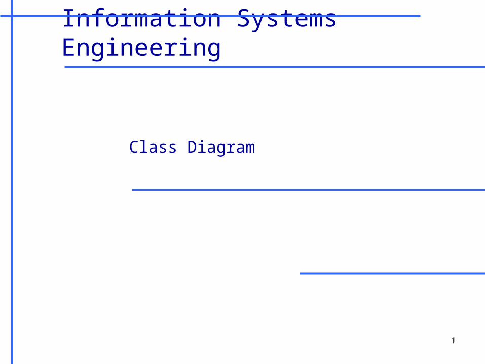
diagrams UML
2
*Communication diagram(Collaboration diagram)
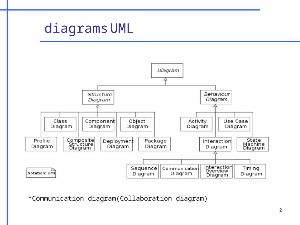
Class Diagram
• A Class diagram is used to display some of the classes and packages in your system
• It gives you a static picture of the pieces in the system and of the relationships between them
• They help the developers see and plan the structure of the system before the code is written, helping to ensure that the system is well designed from the beginning
3
Class Types: Class Utility
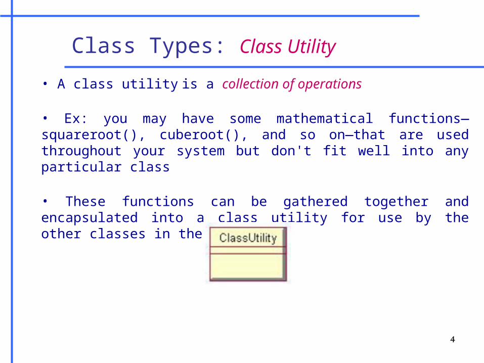
• A class utility is a collection of operations
• Ex: you may have some mathematical functions—squareroot(), cuberoot(), and so on—that are used throughout your system but don't fit well into any particular class
• These functions can be gathered together and encapsulated into a class utility for use by the other classes in the system
4
Class Types: Abstract Class
• Abstract Class - is a class that will not be instantiated. In other words, if Class A is abstract, there will never be any objects of Type A in memory.
•it exists extensively for inheritance and it must be inherited. There are scenarios in which it is useful to define classes that is not intended to instantiate; because such classes normally are used as base-classes in inheritance hierarchies.(Animal class Example)
5

Class Specifications
• Class Name - Unique Name, No spaces, Short, Starting with an upper-case letter
• Class Visibility • Public - the class can be seen by all of the other classes in the system• Protected or private - the class can be seen in nested classes
• Class Multiplicity - The number of instances that you expect to have of a class
• Storage Requirements for a Class - The amount of memory you expect each object of the class to require
6
Class Specifications cont.
• Class Persistence • Persistent – the information in objects of the class will be saved to a database or some other form of persistent storage• Transient – the information in objects of the class will not be saved to persistent storage
7
Class Attributes Specifications
• Data Type (e.g. string, double, int, etc..)
• Initial Value – Not required
• Visibility• Public - the attribute is visible to all other classes ( + )• Private - the attribute is not visible to any other class ( - )• Protected - the class and any of its descendants have access
to the attribute (#)
8
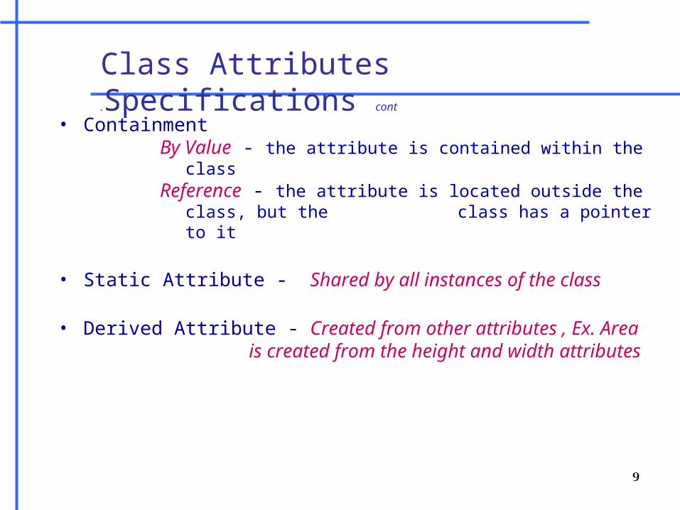
Class Attributes Specifications cont.
• Containment By Value - the attribute is contained within the classReference - the attribute is located outside the class, but
the class has a pointer to it
• Static Attribute - Shared by all instances of the class
• Derived Attribute - Created from other attributes , Ex. Area is created from the height and width
attributes
9
Class Operations
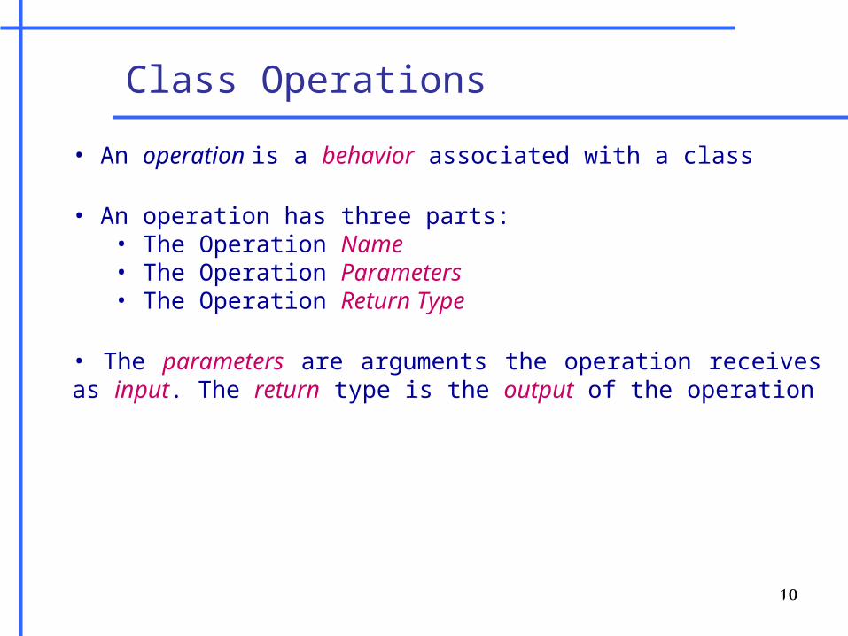
• An operation is a behavior associated with a class
• An operation has three parts: • The Operation Name• The Operation Parameters • The Operation Return Type
• The parameters are arguments the operation receives as input. The return type is the output of the operation
10
Practice
• Draw the classes found in the ATM Withdraw Money use case
•Classes•Attributes•Operations
11
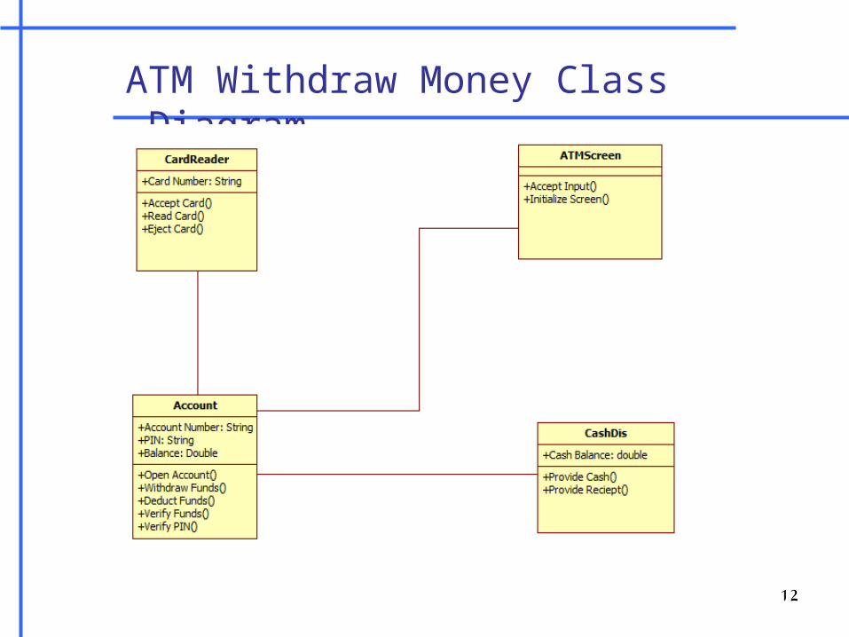
ATM Withdraw Money Class Diagram
12
Related Documents