This article appeared in a journal published by Elsevier. The attached copy is furnished to the author for internal non-commercial research and education use, including for instruction at the authors institution and sharing with colleagues. Other uses, including reproduction and distribution, or selling or licensing copies, or posting to personal, institutional or third party websites are prohibited. In most cases authors are permitted to post their version of the article (e.g. in Word or Tex form) to their personal website or institutional repository. Authors requiring further information regarding Elsevier’s archiving and manuscript policies are encouraged to visit: http://www.elsevier.com/authorsrights

Welcome message from author
This document is posted to help you gain knowledge. Please leave a comment to let me know what you think about it! Share it to your friends and learn new things together.
Transcript
This article appeared in a journal published by Elsevier. The attachedcopy is furnished to the author for internal non-commercial researchand education use, including for instruction at the authors institution
and sharing with colleagues.
Other uses, including reproduction and distribution, or selling orlicensing copies, or posting to personal, institutional or third party
websites are prohibited.
In most cases authors are permitted to post their version of thearticle (e.g. in Word or Tex form) to their personal website orinstitutional repository. Authors requiring further information
regarding Elsevier’s archiving and manuscript policies areencouraged to visit:
http://www.elsevier.com/authorsrights
Author's personal copy
Influence of thermoelectric junctions on the electrical signalsgenerated by the tool–workpiece thermocouple system inmachining
Mário C. Santos Jr. a, Álisson R. Machado a,⇑, Marcos A.S. Barrozo b, Luciano M. Neto c,Ernane A.A. Coelho c
a Laboratory for Teaching and Research in Machining, School of Mechanical Engineering, Federal University of Uberlandia, Av. João Naves de Ávila, 2121, MinasGerais CEP 38408100, Brazilb School of Chemical Engineering, Federal University of Uberlandia, Av. João Naves de Ávila, 2121, Minas Gerais CEP 38408100, Brazilc School Electrical Engineering, Federal University of Uberlandia, Av. João Naves de Ávila, 2121, Minas Gerais CEP 38408100, Brazil
a r t i c l e i n f o
Article history:Received 31 August 2011Received in revised form 16 April 2013Accepted 26 April 2013Available online 16 May 2013
Keywords:Tool–workpiece thermocouple systemThermoelectrical motive forceTurning process
a b s t r a c t
This work investigates the influence of the electrical circuits on TMF (total thermoelectro-motive force) response signals captured from the rotating workpiece generated by thetool–workpiece thermocouple system in turning process considering four different ther-moelectrical circuits – Ec namely: C1 – bronze pin, C2 – aluminum pin, C3 – graphite brushand C4 – liquid mercury contact. The tests were carried out under different cutting condi-tions. A multifactorial analysis of variance was performed using the 2k factorial design,always considering the C4 as the lower level. In addition, a single factor analysis of variancewas performed, keeping the cutting speed, Vc, the feed rate, f, the depth of cut, doc, and thelubri-coolant system, Lub, constants while varying the Ec in order to validate the resultsfound with the factorial design. The results indicated that there was no statistical signifi-cant difference in the TMF responses of the tool–workpiece thermocouples C1 and C4 aswell as C2 and C4. However, when comparing the TMF generated by C3 and C4 a significantdifference was detected, indicating that graphite brushes is not recommended for suchapplication, while the bronze and aluminum pins can be thought as an advantageous sub-stitute for the laborious liquid mercury system.
� 2013 Elsevier Ltd. All rights reserved.
1. Introduction
The action of the cutting tool causes intense plasticdeformations on the primary and secondary shear zonesof the machined material, whose work is converted almostentirely into heat around the cutting edge of the tool [1–3].In machining high productivity is always pursued and thisis usually achieved increasing the cutting speed and feedrate which in turn increases deformation rates of the work
material and hence the cutting temperature, principallywhen cutting high resistance and high melting point mate-rials [2,4–7].
Among the main problems that high cutting tempera-tures can cause are tool wear, residual stresses and work-piece distortions [2,8,9] especially in thin-walledworkpieces [7]. Measuring the temperature in machiningis not an easy task but important in order to study itsbehavior and effect on the product quality. A method formeasuring the cutting temperature that is widely em-ployed to monitor the temperature in the region of thechip–tool interface is the tool–workpiece thermocouplesystem [10–12].
0263-2241/$ - see front matter � 2013 Elsevier Ltd. All rights reserved.http://dx.doi.org/10.1016/j.measurement.2013.04.056
⇑ Corresponding author. Tel.: +55 34 3239 4031; fax: +55 3432394206.E-mail addresses: [email protected] (M.C. Santos Jr.), alissonm@me-
canica.ufu.br (Á.R. Machado), [email protected] (M.A.S. Barrozo),[email protected] (L.M. Neto), [email protected] (E.A.A. Coelho).
Measurement 46 (2013) 2540–2546
Contents lists available at SciVerse ScienceDirect
Measurement
journal homepage: www.elsevier .com/ locate /measurement
Author's personal copy
A thermocouple signal is generated by the electrical po-tential difference formed by the movement of electricalcharge (tmf: thermoelectrical motive forces) between twodifferent materials in contact due to the temperature gra-dient between its ends [13]. Two main laws govern a ther-mocouple circuit: (1) A thermoelectric current cannot besustained in a circuit of a single homogeneous material,however, varying in cross section, by the application ofheat alone; and (2) the algebraic sum of the thermoelectri-cal motive forces in a circuit composed of any number ofdissimilar materials is zero if all of the circuits are at a uni-form temperature [14].
In machining, the cutting temperature at the chip–toolinterface can be determined by a thermoelectrical motiveforce which is proportional to the temperature in that re-gion [8]. A technique that has provided good results inthe acquisition of the TMF signal from the tool–workpiecethermocouple in turning processes is the one that uses amercury bath to provide contact with the rotating work-piece and hence shutting the electrical circuit [5]. How-ever, this method may involve some inconveniences suchas environmental contamination if the mercury bath isnot hermetically closed or encapsulated because this is avery toxic chemical element; and depending on the setup,it may generate vibrations, particularly under severe cut-ting conditions.
Another way to capture the voltage signal of the tool–workpiece thermocouple is by using a conducting elementsuch as a graphite brush sliding on the workpiece surface[15]. However, depending on the surface quality and thecollection point on the workpiece, it may generate consid-erable noise in the TMF.
The two main difficulties in using a tool–workpiecethermocouple system during machining for acquisition ofthe TMF signal of the tool–workpiece interface are: (i) toacquire the TMF signal from the rotating workpiece; (ii)the TMF signal measured by the multimeter is actuallythe algebraic sum of the thermoelectric motive forces(tmf) generated by all the junctions that such electrical cir-cuit is comprised of.
The aim of the present work is to compare the simul-taneous TMF (total Thermoelectrical Motive Force) re-sponses produced by four different circuits (C1, C2, C3
and C4) used for the tool–workpiece thermocouple systemwhen turning an AA-6263 aluminum alloy. In these cir-cuits there are several thermoelectrical motive junctions(Ji) that allow the passage of electrical current. The pinsthat make contact with the rotating workpiece of the C1,C2 and C3 circuits are made of different materials (bronze,pure-aluminum and graphite) while C4 circuit make con-tact with aluminum-bar by mean of the traditional metal-lic liquid mercury bath. The TMF4 response of the C4
circuit was taken as the reference for the comparisonsassigned.
Although liquid mercury is a material of high thermalconductivity and low friction coefficient and hence it nor-mally provides a noiseless electrical circuit of the tradi-tional tool–workpiece thermocouple system, this workaims to look for a possible substitute, in order to simplifythe system, as well as eliminate safety risks that the toxicmetallic mercury may cause.
2. Experimental procedure
2.1. Workpiece material and consumables
In this experiment an AA-6263 aluminum alloy bar(�£80 � 400 mm) was used as work material with thechemical composition and properties given in Tables 1and 2, respectively.
In the wet machining condition a base vegetable oil(Vasco 1000 – manufactured by Blaser Swisslube) withthe properties given in Table 3, was used at a concentrationof 6% (checked with an Atago hand refractometer). It waspumped in the cutting area through a nozzle with a flowrate of 360 L/h.
2.2. Equipment and tools
Turning was carried out on an Imor 520 lathe with 11 kWof power manufactured by Indústrias Romi S.A. A toolholderwith ISO specification ‘‘DCGT3252-AL/KS05F’’ and N05 ce-mented carbide inserts (ISO specification ‘‘DCGT11T308-AL KS05F’’) manufactured by OSG-Tungaloy were used.When an insert is mounted on the toolholder, the followinggeometry is derived: ao = 7� (clearance angle); co = 20� (rakeangle) and vr = 90� (approach angel). The TMF on the electri-cal circuits was measured with an high impedance (1 M X)voltmeter, Agilent 34970A (resolution of 0.000001 V).
2.3. Factorial design and analysis of variance
To carry out the experimental investigation a 24 factorialdesign was used with the following input factors: cuttingspeed, feed rate, lubri/cooling condition and the electricalcircuit. The low (�1) and high (+1) levels of the factors were:cutting speed – Vc (73 m/min, 363 m/min); feed rate – f(0.138 mm/rev, 0.388 mm/rev); lubri/cooling condition –Lub (dry, wet) and electrical circuit – Ec (C1, C2, C3, C4), whichhas generated the TMF1, TMF2, TMF3 and TMF4 keeping thedepth of cut (doc) constant at 0.5 mm. Since the Ec had fourlevels, the analysis of variance/significance of the factors
Table 1Chemical composition of the AA-6263 aluminum alloy.
Elements Al Si Cu Mg
Weights (%) 98 0.40–0.60 0.28 0.70–1.00
Table 2Properties of the work material (25 �C).
Properties Density (g/cm3)
Young modulus(GPa)
Tensile strength(MPa)
Values 2.7 70–80 90
Table 3Properties of the cutting fluid (Vasco 1000) according to the manufacturer.
Properties Density (g/cm3) Viscosity (mm2/s) Flashpoint (�C)
Value 0.95 (20 �C) 56 (40 �C) 180
M.C. Santos Jr. et al. / Measurement 46 (2013) 2540–2546 2541
Author's personal copy
was carried out in pairs, always considering C4 (mercurysystem) as the lower level.
A single factor analysis of variance was also performedwith the aim of checking the results found through facto-rial design with the factors Vc = 178 m/min;f = 0.204 mm/rev; doc = 0.75 mm and Lub = dry kept con-stants while the Ec was varied. The experimental design in-volved samples from 40 observations of each treatment.
2.4. Electrical circuits of the tool–workpiece thermocouplesystem
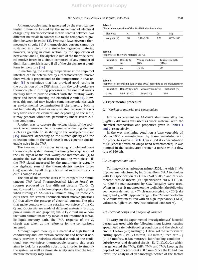
Fig. 1 presents a schematic draw of the four thermocou-ple workpiece systems (C1, C2, C3 and C4) used to simulta-neously capture the TMF responses during machining tests.A technyl body (�£100 � 200 mm) with mercury is usedfor the C4 electrical circuit. It is basically composed of amain shaft of copper (�£20 � 100 mm) which is in con-tact with the workpiece, hence rotating with it, mountedbetween two bearings, fixed at a stationary technyl body(Fig. 1). Inside this body there is a channel filled with liquidmercury that is in contact with the copper shaft and a wirethat captures the electrical signal from the system. Thetechnyl chamber has also a mandrel that is mounted intothe tailstock of the lathe. All its elements are carefully elec-trical insulated from the structure of the lathe.
C1 is consisted of the junctions J1, . . ., J7; C2 of the junc-tions J1, . . ., J5, J8 and J9; C3 of the junctions J1, . . ., J4, J10 andJ11 and C4 of the junctions J1, . . ., J4, J12, . . ., J15. All representedby the dotted line ellipses. J1 is the hot-junction formed bythe tool (carbide insert)–workpiece (aluminum-bar) ther-mocouple, where intense heat is generated by the machin-ing process, being thereby the junction of main interest tostudy the temperature into the tool–chip interface duringthe machining tests. All the others (J2 to J15) are junctionsneeded for completing the four electrical circuits.
J2 is the carbide insert – toolholder junction; J3 is thetoolholder – commercial copper wires (�£0.75 mm �1500 mm) junctions. The toolholder was properly insulated
from the rest of the machine’s structure by means of acrylicblades (shims) illustrated in Fig. 2.
J4 is the copper wire – multimeter’s copper connectorjunctions; J5 is the copper wire – commercial pure alumi-num support junctions. They were joined by electricalwelding. The supports (�£12 mm � �150 mm) have a
Fig. 1. Electrical circuits of the tool–workpiece thermocouple system.
Fig. 2. The (J3) copper wire – toolholder junctions insulated by acrylicblades.
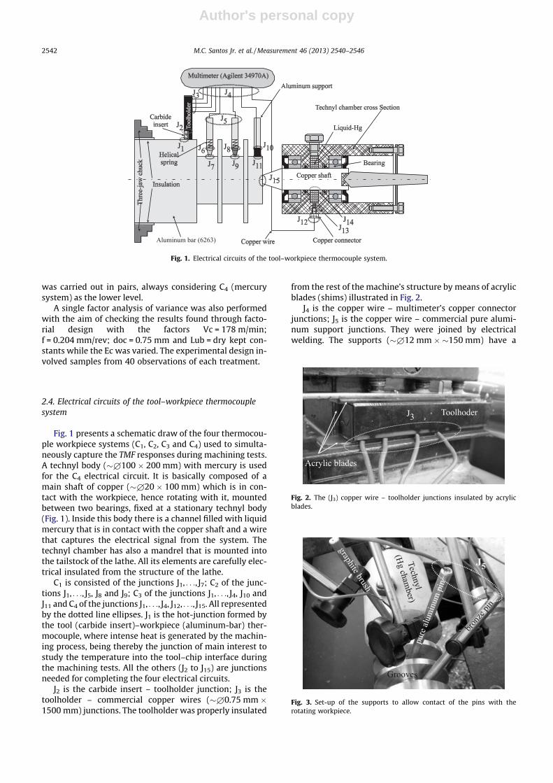
Fig. 3. Set-up of the supports to allow contact of the pins with therotating workpiece.
2542 M.C. Santos Jr. et al. / Measurement 46 (2013) 2540–2546
Author's personal copy
small hole drilled in one of their ends (�£9 mm ��20 mm) to allow the aluminum and bronze pins bemounted in them. Fig. 3 presents the set-up of the supportsof the pins, where J5 junctions can be seen. Grooves weremachined in the workpiece to allow the contacts of thepins.
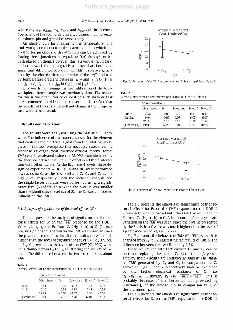
Both J6 and J8 are the pure aluminum support – bronzeand pure-aluminum pins (�£8.90 mm � 15 mm) junc-tions, respectively. The pure-aluminum and bronze pinswere inserted into the blind holes of the aluminum sup-ports as showed in Fig. 4. Helical springs (�£8.5 � 10 mm)were used to press the pins against the rotating cylindricalsurface of the workpiece (force of approximately 10 N) inthe grooves prepared specifically for this purpose, asshown in Fig. 3.
J7, J9 and J11 are the aluminum workpiece bar – bronze(ASTM 51000) and pure aluminum (99.95%) pins and com-mercial graphite (density of 2.0 g/cm3 and particles sizes of30–40 lm) brush junctions, respectively. These junctionswere mounted near to the center of the bar (radius of15.5 mm) to reduce the peripheral speed and thus the ki-netic friction effect that could generate heat in the junc-tions. In the two former junctions a fine layer of lubricantoil (Texamatic B fluid) was used to reduce the friction be-tween the moving parts, without, however, affecting theelectrical conductivity between them.
The graphite brush was fixed in a solid aluminum sup-port by means of a rigid adhesive tape without electricalcontact between them (see Fig. 4). J10 is the copper wire– graphite brush junction. J12 is the cooper wire – copperconnector (under the technyl cylinder) junction; J13 is thecopper connector – liquid mercury inside of the technylchamber, junction; J14 is the liquid mercury – copper shaft(inside the technyl chamber) junction; and finally, J15 is thecopper shaft – aluminum workpiece bar junction.
2.5. Electrical circuits of the thermocouple
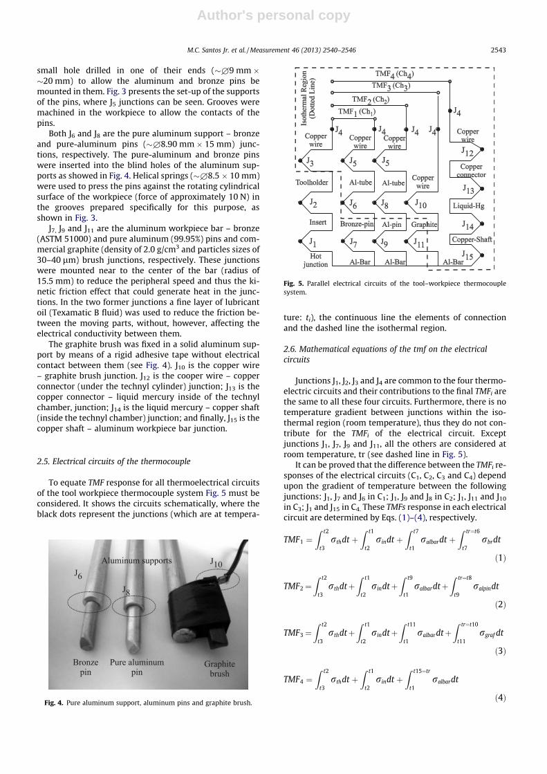
To equate TMF response for all thermoelectrical circuitsof the tool workpiece thermocouple system Fig. 5 must beconsidered. It shows the circuits schematically, where theblack dots represent the junctions (which are at tempera-
ture: ti), the continuous line the elements of connectionand the dashed line the isothermal region.
2.6. Mathematical equations of the tmf on the electricalcircuits
Junctions J1, J2, J3 and J4 are common to the four thermo-electric circuits and their contributions to the final TMFi arethe same to all these four circuits. Furthermore, there is notemperature gradient between junctions within the iso-thermal region (room temperature), thus they do not con-tribute for the TMFi of the electrical circuit. Exceptjunctions J1, J7, J9 and J11, all the others are considered atroom temperature, tr (see dashed line in Fig. 5).
It can be proved that the difference between the TMFi re-sponses of the electrical circuits (C1, C2, C3 and C4) dependupon the gradient of temperature between the followingjunctions: J1, J7 and J6 in C1; J1, J9 and J8 in C2; J1, J11 and J10
in C3; J1 and J15 in C4. These TMFs response in each electricalcircuit are determined by Eqs. (1)–(4), respectively.
TMF1 ¼Z t2
t3rthdt þ
Z t1
t2rindt þ
Z t7
t1ralbardt þ
Z tr¼t6
t7rbrdt
ð1Þ
TMF2¼Z t2
t3rthdtþ
Z t1
t2rindtþ
Z t9
t1ralbardtþ
Z tr¼t8
t9ralpindt
ð2Þ
TMF3¼Z t2
t3rthdtþ
Z t1
t2rindtþ
Z t11
t1ralbardtþ
Z tr¼t10
t11rgraf dt
ð3Þ
TMF4 ¼Z t2
t3rthdt þ
Z t1
t2rindt þ
Z t15¼tr
t1ralbardt
ð4ÞFig. 4. Pure aluminum support, aluminum pins and graphite brush.
Fig. 5. Parallel electrical circuits of the tool–workpiece thermocouplesystem.
M.C. Santos Jr. et al. / Measurement 46 (2013) 2540–2546 2543
Author's personal copy
where rth, rin, ralbar, rbr, ralpin and rgraf are the SeebeckCoefficient of the toolholder, insert, aluminum bar, bronze,aluminum-pin and graphite, respectively.
An ideal circuit for measuring the temperature in atool–workpiece thermocouple system is one in which theti = 0 �C for junctions with i – 1. This can be achieved byforcing those junctions be equals to 0 �C through an icebath placed on them. However, this is a very difficult task.
In this work the main goal is to prove that there is nosignificant difference between the TMF responses gener-ated by the electric circuits, in spite of the tmf’s inducedby temperature gradient between J1, J7 and J6 in C1; J1, J9
and J8 in C2; J1, J11 and J10 in C3; J1 and J15 in C4.It is worth mentioning that no calibration of the tool–
workpiece thermocouple was previously done. The reasonfor this is the difficulties of calibrating such systems thatuses cemented carbide tool tip inserts and the fact thatthe results of this research will not change if the tempera-ture were used instead.
3. Results and discussion
The results were analysed using the Statistic 7.0 soft-ware. The influence of the materials used for the elementthat captures the electrical signal from the rotating work-piece in the tool–workpiece thermocouple system on theresponse (average total thermoelectrical motive force:TMF) was investigated using the ANOVA, considering onlythe thermoelectrical circuits – Ec effects and their interac-tion with other factors. As the Ecs have 4 levels, three de-sign of experiments – DOE (I, II and III) were performedalways using C4 as the low level and C1, C2 and C3 as thehigh level, respectively. Both the factorial analysis andthe single factor analysis were performed using a signifi-cance level (a) of 5%. Thus when the p-value was smallerthan the significance level (a) of 5% the Ec was consideredinfluent on the TMF.
3.1. Analysis of significance of factorial effects (2k)
Table 4 presents the analysis of significance of the fac-torial effects for Ec on the TMF response for the DOE I.When changing the Ec from C4 (Hg bath) to C1 (bronzepin) no significant variation on the TMF was observed sincethe p-value presented by the Statistic software was muchhigher than the level of significance (a) of 5%, i.e., 37.15%.
Fig. 6 presents the behavior of the TMF (CI: 95%) whenEc is changed from C4 to C1, illustrating the results of Ta-ble 4. The difference between the two circuits Ec is about14%.
Table 5 presents the analysis of significance of the fac-torial effects for Ec on the TMF response for the DOE II.Similarly to what occurred with the DOE I, when changingEc from C4 (Hg bath) to C2 (aluminum pin) no significantvariation on the TMF was seen, since the p-value presentedby the Statistic software was much higher than the level ofsignificance (a) of 5%, i.e., 32.29%.
Fig. 7 presents the behavior of TMF (CI: 95%) when Ec ischanged from C4 to C2, illustrating the results of Tab. 5. Thedifference between the two Ec is only 2.7%.
These results indicate that circuits C1 and C2 can beused for replacing the circuit C4, since the tmfs gener-ated by these circuits are statistically similar. The smal-ler TMF generated by C1 and C2 in comparison to C4
shown in Figs. 6 and 7 respectively may be explainedby the higher electrical resistance of C4, i.e,R4 > R1 > R2. Although, R1 > R2, TMF2 > TMF1. This isprobably because of the better contact provided byjunctions J7 of the bronze pin in comparison to J9 ofthe aluminum pin.
Table 6 presents the analysis of significance of the fac-torial effects for Ec on the TMF response for the DOE III.
Table 4Factorial effects for Ec and interactions in DOE I (R-sqr = 0.85866).
Sources of variation
Mean/Interc. Ec Ec vs. Lub Ec vs. f Ec vs. Vc
Effect 2.41 �0.37 �0.37 0.38 �0.37Std.Err. 0.19 0.38 0.38 0.38 0.38t 12.67 �0.98 �0.97 0.98 �0.98p-Value (%) 0.01 37.15 37.70 37.01 37.13
Fig. 6. Behavior of the TMF response when Ec is changed from C4 to C1.
Table 5Factorial effects for Ec and interactions in DOE II (R-sqr = 0.99515).
Source variations
Mean/Interc. Ec Ec vs. Lub Ec vs. f Ec vs. Vc
Effect 2.56 �0.08 �0.15 0.11 0.14Std.Err. 0.04 0.07 0.07 0.07 0.07t 73.84 �1.10 �2.10 1.58 1.94p-Value (%) �0.01 32.29 9.01 17.57 10.95
Fig. 7. Behavior of the TMF when Ec is changed from C4 to C2.
2544 M.C. Santos Jr. et al. / Measurement 46 (2013) 2540–2546
Author's personal copy
Contrary to what happened to the DOEs I and II, the resultsshowed that there is a significant influence of the electricalcircuits on the TMF since the p-value of 1.21% calculated byStatistical software is lower than a of 5%.
Fig. 8 presents the behavior of TMF (CI: 95%) when Ec ischanged from C4 (Hg bath) to C3 (graphite brush), illustrat-ing the results of Table 6. The TMF response has increasedabout 161%. With this result the circuit C3, with the graph-ite brushes, cannot replace the electrical circuit C4. Proba-bly the contact of the graphite brush with the workpiece(junctions J10 and J11), generates sufficient noises thatinterfere the TMF signals.
The behavior of TMF measured by the Ec C1 is due to thehigher electrical resistance of this electrical circuit.Although R4 > R3, adhering material accumulates betweenthe graphite brush and the aluminum-bar in the junctionJ11, that could change the electrical resistance of the Ec.This is clearly seen in Fig. 9. This adhering material will af-fect the continuous contact of the brush against the alumi-num bar, causing a wide dispersion of the response. This ispossibly increasing the electrical resistance.
3.2. Single factor analysis of variance
Table 7 presents the single factor analysis of variance atfour levels of Ec (C1, C2, C3, C4). It confirms that there aredifferences in the TMF responses among them when theyare compared all together, since the p-value is much lowerthan the significance level of 5%.
Fig. 10 illustrates the TMF of these electrical circuits,where it is clear that Ec C3 generates the highest valuesamong them all, confirming that the graphite brush differfrom the other circuits.
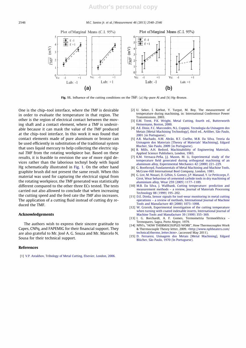
Figs. 11a and b present the expected general behavior ofTMF when the cutting speed (Vc), feed rate (f) and lubri-
colling condition are varied. In Fig. 11a considering thepairs Hg–pure Al and Fig. 11b Hg–Bronze.
It can be observed that when increasing the cuttingspeed and the feed rate individually the TMF, representingthe chip–tool interface temperature, also increases. Whena cutting fluid is used a small drop in the cutting tempera-ture is also seen. These are in accordance with the litera-ture [3,5] that indicates that the cutting speed and feedrate are directly proportional to the chip–tool interfacetemperature and the lubricant action of the cutting fluidis most probably the responsible for the reduction of theheat generated when wet cut is performed.
4. Conclusions
In a tool–workpiece thermocouple system there are twocritical regions that can generate TMFs in response to heat.
Table 6Factorial effects for Ec and interactions in design experiment III (R-sqr = 0.83241).
Sources of variation
Mean/Interc.
Ec Ec vs. Lub Ec vs. f Ec vs. Vc
Effect 4.70 4.21 �1.24 0.32 �0.51Std.Err. 0.55 1.10 1.10 1.10 1.10t 8.59 3.84 �1.13 0.29 �0.46p-Value (%) 0.04 1.21 31.04 78.32 66.29
Fig. 8. Behavior of the TMF when Ec is changed from C4 to C3.
Fig. 9. A view of the junctions with the aluminum workpiece of theelectrical circuits C1 (bronze pin – J7); C2 (aluminum pin – J9) and C3
(graphite brush – J11) with adhering material in the latter.
Table 7Single factor analysis of variance for TMF.
Effective hypothesis decomposition
SS dof MS F p-Value (%)
Intercept 683.76 1 683.76 102146.60 �0.01EC 0.43 3 0.14 21.50 0.00Error 1.04 156 0.01
Fig. 10. Influence of the electric circuit C1, C2, C3 and C4 on the TMF.
M.C. Santos Jr. et al. / Measurement 46 (2013) 2540–2546 2545
Author's personal copy
One is the chip–tool interface, where the TMF is desirablein order to evaluate the temperature in that region. Theother is the region of electrical contact between the mov-ing shaft and a contact element, where a TMF is undesir-able because it can mask the value of the TMF producedat the chip–tool interface. In this work it was found thatcontact elements made of pure aluminum or bronze canbe used efficiently in substitution of the traditional systemthat uses liquid mercury to help collecting the electric sig-nal TMF from the rotating workpiece bar. Based on theseresults, it is feasible to envision the use of more rigid de-vices rather than the laborious technyl body with liquidHg schematically illustrated in Fig. 1. On the other handgraphite brush did not present the same result. When thismaterial was used for capturing the electrical signal fromthe rotating workpiece, the TMF generated was statisticallydifferent compared to the other three ECs tested. The testscarried out also allowed to conclude that when increasingthe cutting speed and the feed rate the TMF also increases.The application of a cutting fluid instead of cutting dry re-duced the TMF.
Acknowledgements
The authors wish to express their sincere gratitude toCapes, CNPq, and FAPEMIG for their financial support. Theyare also grateful to Mr. José A. G. Souza and Mr. Marcelo N.Sousa for their technical support.
References
[1] V.P. Astakhov, Tribology of Metal Cutting, Elsevier, London, 2006.
[2] U. Seker, _I. Korkut, Y. Turgut, M. Boy, The measurement oftemperature during machining, in: International Conference PowerTransmissions, 2003.
[3] E.M. Trent, P.K. Wright, Metal Cutting, fourth ed., ButterworthHeinemann, Boston, 2000.
[4] A.E. Diniz, F.C. Marcondes, N.L. Coppini, Tecnologia da Usinagem dosMetais [Metal Machining Technology], third ed., Artliber, São Paulo,2001 (in Portuguese).
[5] A.R. Machado, A.M. Abrão, R.T. Coelho, M.B. Da Silva, Teoria daUsinagem dos Materiais [Theory of Materials’ Machining], EdgardBlucher, São Paulo, 2009 (in Portuguese).
[6] B. Mills, A.H. Redord, Machinabilitty of Engineering Materials,Applied Science Publishers, London, 1983.
[7] K.M. Vernaza-Pefia, J.J. Mason, M. Li, Experimental study of thetemperature field generated during orthogonal machining of analuminum alloy, Experimental Mechanics 42 (2000) 221–229.
[8] G. Boothroyd, Fundamentals of Metal Machining and Machine Tools,McGraw-Hill International Bool Company, London, 1981.
[9] G. List, M. Nouari, D. Géhin, S. Gomez, J.P. Manaud, Y. Le Petitcorps, F.Girot, Wear behaviour of cemented carbide tools in dry machining ofaluminium alloy, Wear 259 (2005) 1177–1189.
[10] M.B. Da Silva, J. Wallbank, Cutting temperature: prediction andmeasurement methods – a review, Journal of Materials ProcessingTechnology 88 (1999) 195–202.
[11] D.E. Dimla, Sensor signals for tool-wear monitoring in metal cuttingoperations – a review of methods, International Journal of MachineTools and Manufacture 40 (2000) 1073–1098.
[12] W. Grzesik, Experimental investigation of the cutting temperaturewhen turning with coated indexable inserts, International Journal ofMachine Tools and Manufacture 39 (1999) 355–369.
[13] I. G. Borchardt, A. F. Gomes, Termometria Termoelétrica –Termopares, Sagra, Porto Alegre, 1979.
[14] NPH’s, ‘‘HOW THERMOCOUPLES WORK’’, How Thermocouples Work& Thermocouple Theory letter, 2009. <http://www.nphheaters.com/technical/thermo_letter.htm>. (accessed May 2011).
[15] D. Ferraresi, Usinagem dos Metais [Metal Machining], EdgardBlücher, São Paulo, 1970 (In Portuguese).
(a) (b)Fig. 11. Influence of the cutting conditions on the TMF: (a) Hg–pure Al and (b) Hg–Bronze.
2546 M.C. Santos Jr. et al. / Measurement 46 (2013) 2540–2546
Related Documents