Proceedings of the 5 th Manufacturing Engineering Society International Conference – Zaragoza – June 2013 Influence of the Process Parameters to Manufacture Micro- cavities by Electro Discharge Machining (EDM) D. Gurguí (1) , E. Vázquez, I. Ferrer (1) Departamento de Ingeniería Mecánica y Construcción Industrial, Universidad de Girona, Av/ Lluís Santaló s/n, Girona 17003, SPAIN. [email protected] ABSTRACT Increasing demand on micro-product has driven the development of innovative manufacturing process to this new requirements as well as the adaptation of conventional metal cutting process to these micro-scale applications. In the medical field a huge variety of micro products can be found in prosthesis, surgery devices or tissue engineering. This paper researches the application of the conventional EDM process to manufacture micro cavities with the objective to obtain how the process parameters could effects on the result. As a result the dimensions and shape of the micro-cavities are analyzed. Keywords: EDM technology; Die-sinking EDM; micromachining; micro-cavities. 1. Introduction Electro-discharge machining (EDM) is a thermal process by which conductive material can be machined using electric discharges. The process is based on applying a voltage between the tool electrode and the workpiece while both are immersed in a dielectric fluid. During the process, the tool and workpiece are at a distance of microns when a plasma channel is created between the anode and cathode. Most of the electrical energy is transformed into thermal energy and the material melts or vaporizes instantly. This absence of contact between the tool and the workpiece and the use of thermal energy for machining make this technology highly suitable for applications where really hard materials are required solving important problems such as residual stress, chatter and other vibrations due its negligible cutting force [1].Micro-EDM is capable that holes have to be machined with diameters smaller than 5 µm and with surface roughness (Rmax) less than 0.1 µm [2]. Typical hole diameters range from 8 to 500 mm and depth to diameter ratios (L/d) of 20 or more can be achieved [3]. The downscaling of the manufacture processes requires a new approach to EDM process design. Typically micro-EDM has tended to use conventional EDM machines adapting to ensure the new requirements of micro-manufacturing, due to issues in the process manifested. The main limitations of EDM are that only conductive materials can be machined and that the tool electrodes have to be replaced regularly due to the tool wear, principally with not suitable machining conditions [1,4]. The needing to produce accurate three-dimensional cavities, convert the electro wear in interest topic of research In conventional die-sinking electro discharge machining (EDM), the problem of wear occurring on the electrode is well-known [5]. The solution of this problem usually is using a number of electrodes to produce a cavity. The error caused by electrode wear often insignificant due to the feature sizes and tolerances required. The machining conditions in micro-EDM differ significantly from those in conventional EDM [6]. The usual die-sinking method based on employing electrodes for roughing followed by electrodes for finishing is not applicable due to the cost of multiple electrodes with microfeatures. In addition, the microfeatures will suffer severe wear resulting in the need for even more electrodes. Tool wear is affected by the precipitation of carbon from the hydrocarbon dielectric on to the electrode surface during sparking according to Mohri et al [5]. They also found that the reason of the rapid wear of the electrode edge portion was due to the failure of carbon to precipitate at the region with large curvature. The first challenge related with tool wear is accurately measuring the amount of wear due to very small wear volumes are involved. The tool wear can be divided in two aspects, deformation of the electrode shape and volumetric wear [7]. Rajurkar et al. [8] also investigated the uniform wear method (UWM). They achieved integrate CAD/CAM system (commercially available) with the uniform wear method in order to compensate for tool wear and finally produce complex 3D

Welcome message from author
This document is posted to help you gain knowledge. Please leave a comment to let me know what you think about it! Share it to your friends and learn new things together.
Transcript

Proceedings of the 5th Manufacturing Engineering Society International Conference – Zaragoza – June 2013
Influence of the Process Parameters to Manufacture Micro-cavities by Electro Discharge Machining (EDM)
D. Gurguí(1), E. Vázquez, I. Ferrer
(1) Departamento de Ingeniería Mecánica y Construcción Industrial, Universidad de Girona, Av/ Lluís Santaló s/n, Girona 17003, SPAIN. [email protected]
ABSTRACT
Increasing demand on micro-product has driven the development of innovative manufacturing process to this new requirements as well as the adaptation of conventional metal cutting process to these micro-scale applications. In the medical field a huge variety of micro products can be found in prosthesis, surgery devices or tissue engineering. This paper researches the application of the conventional EDM process to manufacture micro cavities with the objective to obtain how the process parameters could effects on the result. As a result the dimensions and shape of the micro-cavities are analyzed.
Keywords: EDM technology; Die-sinking EDM; micromachining; micro-cavities.
1. Introduction
Electro-discharge machining (EDM) is a thermal process by which conductive material can be machined using electric discharges. The process is based on applying a voltage between the tool electrode and the workpiece while both are immersed in a dielectric fluid. During the process, the tool and workpiece are at a distance of microns when a plasma channel is created between the anode and cathode. Most of the electrical energy is transformed into thermal energy and the material melts or vaporizes instantly.
This absence of contact between the tool and the workpiece and the use of thermal energy for machining make this technology highly suitable for applications where really hard materials are required solving important problems such as residual stress, chatter and other vibrations due its negligible cutting force [1].Micro-EDM is capable that holes have to be machined with diameters smaller than 5 µm and with surface roughness (Rmax) less than 0.1 µm [2]. Typical hole diameters range from 8 to 500 mm and depth to diameter ratios (L/d) of 20 or more can be achieved [3]. The downscaling of the manufacture processes requires a new approach to EDM process design. Typically micro-EDM has tended to use conventional EDM machines adapting to ensure the new requirements of micro-manufacturing, due to issues in the process manifested.
The main limitations of EDM are that only conductive materials can be machined and that the tool electrodes have to be replaced regularly due to the tool wear, principally with not suitable machining conditions [1,4]. The needing to produce accurate three-dimensional cavities, convert the electro wear in interest topic of research In conventional die-sinking electro discharge machining (EDM), the problem of wear occurring on the electrode is well-known [5]. The solution of this problem usually is using a number of electrodes to produce a cavity. The error caused by electrode wear often insignificant due to the feature sizes and tolerances required. The machining conditions in micro-EDM differ significantly from those in conventional EDM [6]. The usual die-sinking method based on employing electrodes for roughing followed by electrodes for finishing is not applicable due to the cost of multiple electrodes with microfeatures. In addition, the microfeatures will suffer severe wear resulting in the need for even more electrodes. Tool wear is affected by the precipitation of carbon from the hydrocarbon dielectric on to the electrode surface during sparking according to Mohri et al [5]. They also found that the reason of the rapid wear of the electrode edge portion was due to the failure of carbon to precipitate at the region with large curvature. The first challenge related with tool wear is accurately measuring the amount of wear due to very small wear volumes are involved. The tool wear can be divided in two aspects, deformation of the electrode shape and volumetric wear [7]. Rajurkar et al. [8] also investigated the uniform wear method (UWM). They achieved integrate CAD/CAM system (commercially available) with the uniform wear method in order to compensate for tool wear and finally produce complex 3D
Proceedings of the 5th Manufacturing Engineering Society International Conference – Zaragoza – June 2013
micro shapes using simple shaped electrodes. The experimental results show that the proposed method successfully addresses the problem of electrode wear in generating tool paths.
According to Ho and Newmann [9] a similar tool wear compensation was investigated by Bleys et al. studied initially evaluated the reduction of tool length based on pulse analysis and subsequently compensated the tool wear by controlling the machining downward feeding movement in real-time. Moreover, Kunieda and Yoshida [10] reduced the tool wear ratio by performing micro-EDM using high-velocity gas as the dielectric medium. They concluded that the tool electrode wear ratio is almost zero for any pulse duration. At the same topic of research, according to Kunieda [11], Kagaya et al. studied to use water as a working fluid and to find characteristics. As a result, high removal rate, low electrode wear and consequently higher working efficiency, without formation of carbonaceous materials are found under optimum experimental conditions, as compared with the case when kerosene is used.
Mahardika and Mitsui [12] propose a new method for monitoring micro-EDM processes by using discharge pulses counting. They found a good agreement between the discharge pulses number and total energy of the discharge pulses to the amount of material removed and the tool electrode wear characteristics for micro-EDM. The tool wear compensation factor was calculated by dividing the volume of tool electrode wear with the total volume of material removed. The tool electrode wear compensation factor can be calculated in order to obtain accurate dimension, since the amount of tool electrode wear is not same in each machining type and condition due to this compensation is only valid for tool electrode of Ag–W and workpiece of brass.
Typically the materials used as tool electrode in micro-EDM are cooper, cemented carbide or tungsten copper, due to acceptable wear behaviour and machinability. Jahan et al. [13] developed an extensive experimental investigation in order to obtain fine surface finish in die-sinking micro-EDM of tungsten carbide using different electrode materials such as tungsten (W), tungsten-copper (CuW) and tungsten-silver (AgW). The effect of different operating parameters in addition to electrode material properties on the finishing micro-EDM of tungsten carbide has been investigated. They conclude that for the finishing micro-EDM of WC, nanosurface can be produced using RC-type pulse generator by minimizing the discharge energy per pulse by means of low gap voltage and capacitance. However, at very low voltage there may be some traces of surface defects due to arcing and short circuits taking place at lower gap width. Among the three electrodes, AgW is the best choice for the finishing micro-EDM of tungsten carbide, giving lower Ra and Rmax, considerably high material removal rate and lower corner wear. However, for faster micro-EDM, CuW can perform well as it exhibits the highest material removal rate and relatively lower electrode wear ratio. Additionally, AgW provides better electrical and thermal properties compared to other EDM electrodes which make it an important choice for the finishing micro-EDM of tungsten carbide.
Blatnik et al. [6] developed experimental study concerning to find the significant machining parameters for the material removal rate (MRR) and to predict and verify the optimal machining parameters. They deduce that the optimal value of the current depends on the electrode size: greater the electrode higher the working and ignition current. Respect to voltage has no significant effect to the material remove rate as long as the machining process is stable. Bamberg and Heamawatanachai [3] studid the effect of the electrode orbital motion for drilling micro-holes on the electrode wear and the MRR. The comparison between orbiting and non-orbiting has been done. The results show that orbiting the axial wear is reduced as a consequence better dimensional accuracy is achieved. The machining time in also reduced and the MMR keep constant along the depth of the hole. Sanchez et. al. [14] Propose the Inverse Slab Electrical Discharge Milling process (ISEDM) process for the set-up of microelectrodes of high aspect ratio with high precision. Materials like hardened steel, graphite and CuW micropins have been tested in several aspect ratio values. Jahan et. al. [15] experimented the effect of vibration frequency and amplitude in micro EDM drilling. The results show that after applying workpiece vibration the MRR increases and EWR decreases significantly. The amounts of deposited debris around the edge of micro-holes reduce significantly after applying vibration. Generally improve the process stability and the efficiency. Garn et. al. [16] investigated the effect of vibrations on micro-EDM process for the start-up process.
The paper is focused on analyzing the effect of the process parameters for manufacturing micro cavities used in several medical field such us grown biological cells, mono fluidics systems for dosing drug, tissue engineering or human DNA testing. The micro cavities dimensions can vary from 400 – 700 µm

Proceedings of the 5th Manufacturing Engineering Society International Conference – Zaragoza – June 2013
depending on the application. After the manufacturing their dimensions and shape were measured in the results.
2. Experimental Setup
The electro discharge machine used to perform the experimentation was an ONA DB 300 SERIES ED (Figure 1). A conventional dielectric fluid was used (ONA oil – specific gravity = 0.760-0.770 gr/cm3). The workpiece material tested in this study was stainless steel 316L. The electrode tools material is electrolytic copper because its good behaviour in steel machining. Higher material removal rates (MRR) with low relative tool wear (RTW) and good surface roughness can be achieved offering a good overall performance.
Figure 1. Setup electro discharge machining. Figure 2. Schematic view of the electrode and orbital
strategy (Without scale).
The electrode tools were manufactured using a Deckel-Maho© 64V Linear. In order to minimize errors, Erowa© clamping device was aligned with machine’s X, Y and Z axis using a dial indicator with 1µm accuracy to provide a fine adjustment between the machined electrodes axis and the subsequent machining path in the EDM machine. The dimensions of the electrode were 400µm x 400µm and 800µm in depth. The Figure 2 shows the schematic view of the electrode and also shows the orbital strategy of the experiment set, the orbital radio was 200 µm, so that the final dimensions of the micro-cavity were 600 µm x 600µm and 100 µm in depth. To determine influential parameters for micro-EDM machining on accuracy and shape of the micro-cavities, 24 experiments have been carried out based on the design of experiments showed in Table 1. In this study, these input parameters were selected according the expertise achieved in previous research work [17].The EDM parameters presented in Table 2 were kept constant during the experimentation to ensure a correct comparison between the 24 tests.
TrayectoriaElectrodo
Orbital Trajectory
Table 1. Variable factors and factor levels of Micro-scale EDM.
Parameters Level 1 Level 2 Level 3 Level 4
Intensity, I [A] 1 2
Voltage, V [V] -200 -120 120 200
Pulse off time, to [µs] 4.8 1.6 3.2
Table 2. Variable factors and factor levels of Micro-scale EDM
Parameters
Servo, S [%] 65
Pulse on time, ti [µs] 3.2
Working Time, Tw [s] 0.8
Pause Time, Tp [s] 0.2

Proceedings of the 5th Manufacturing Engineering Society International Conference – Zaragoza – June 2013
Dimensional measurements in plane XY were performed with a Microscope Discovery 12 from Zeiss© to collect the digital images using Quartz PCI© Software. The measurement of profile on the micro-cavity bottom surface was conducted with a stylus instrument Mitutoyo SV2000 Surftest.
3. Results and Discussion
A total number of 24 micro-cavities were machined with electro discharge machining by following the experimental plan presented in Table 1 and Table 2. The geometrical features and the accuracy are inspected using the imaging system described in Section 2. In order to obtain the measure of micro-cavity, four measurements are conducted as illustrated in Figure 3.
A
D
B C
Figure 3. Top view of final measured micro-cavity (Without scale).
The dimensional and geometrical quality of the micro-cavities produced with electro discharge machining process exhibit large variations. Figure 4 shows some of the micro-cavities produced by using different EDM input parameters. These pictures clearly indicate that in some cases there were formation of recast areas this could be related with the pulse off-time that is not enough to clear all the debris. Furthermore, the circulation of the dielectric liquid and the existent debris in this could be affecting the discharging process.
Figure 4. Micro-cavities results pictures
Proceedings of the 5th Manufacturing Engineering Society International Conference – Zaragoza – June 2013
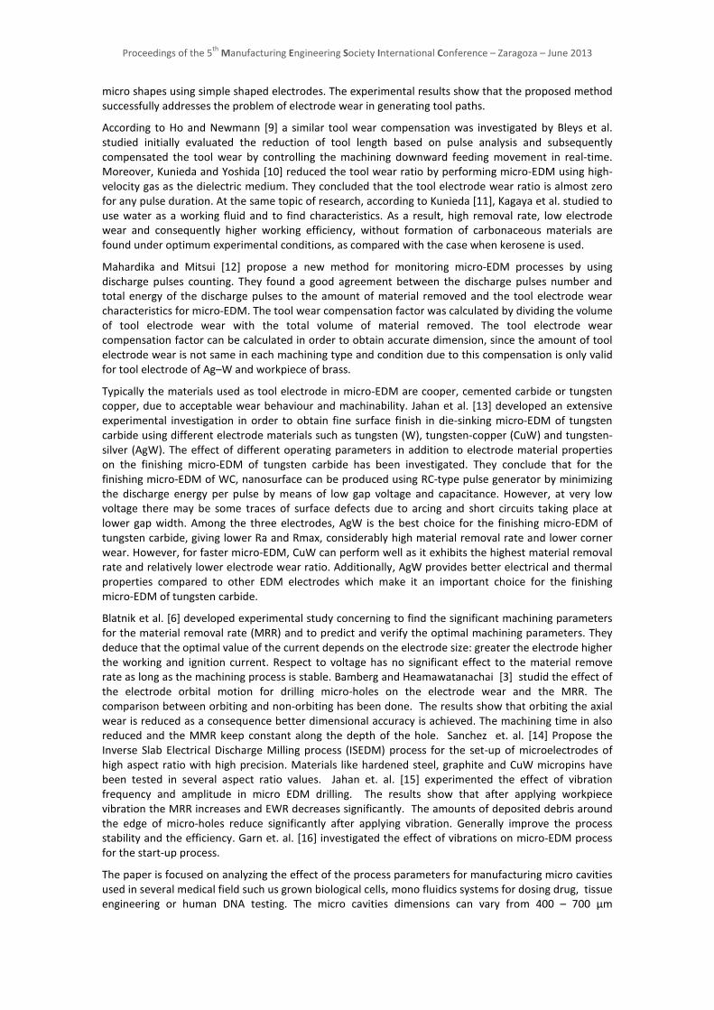
Figure 5a shows the influence of voltage on the accuracy of the final micro-cavity. The results show that there is not trend about the effect of this variable although when -120V was used more dispersion in the data results was detected. The same trend is repeated on the effect of the Peak current although in both values the results are quite grouped around the objective value (Figure 5b).
400
450
500
550
600
650
700
-240 -120 0 120 240
Leng
th o
f sid
e, [µ
m]
Voltage (V), [V]
Length A Length B Length C Length D
a)
400
450
500
550
600
650
700
0 0,5 1 1,5 2 2,5
Leng
th o
f si
de, [
µm]
Peak current (I), [A]
Length A Length B Length C Length D
b) Figure 5. Influence of voltage and peak current on the accuracy of the final micro-cavity.
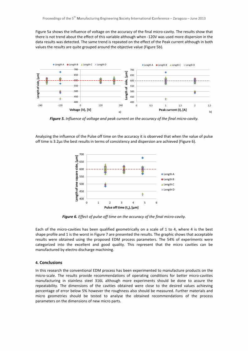
Analyzing the influence of the Pulse off time on the accuracy it is observed that when the value of pulse off time is 3.2µs the best results in terms of consistency and dispersion are achieved (Figure 6).
400
450
500
550
600
650
700
0 1 2 3 4 5 6
Leng
th o
f one
squ
are
side
, [µ
m]
Pulse off time (to), [µm]
Length A
Length B
Length C
Length D
Figure 6. Effect of pulse off time on the accuracy of the final micro-cavity.
Each of the micro-cavities has been qualified geometrically on a scale of 1 to 4, where 4 is the best shape profile and 1 is the worst in Figure 7 are presented the results. The graphic shows that acceptable results were obtained using the proposed EDM process parameters. The 54% of experiments were categorized into the excellent and good quality. This represent that the micro cavities can be manufactured by electro discharge machining.
4. Conclusions
In this research the conventional EDM process has been experimented to manufacture products on the micro-scale. The results provide recommendations of operating conditions for better micro-cavities manufacturing in stainless steel 316L although more experiments should be done to assure the repeatability. The dimensions of the cavities obtained were close to the desired values achieving percentage of error below 5% however the roughness also should be measured. Further materials and micro geometries should be tested to analyse the obtained recommendations of the process parameters on the dimensions of new micro parts.

Proceedings of the 5th Manufacturing Engineering Society International Conference – Zaragoza – June 2013
Figure 7. Effect of voltage, peak current and pulse off time on the geometric quality of the micro-cavity.
5. Acknowledgements
The authors would like to express their gratitude to the Product, Process and Production Engineering Research Group from the University of Girona and ASCAMM Technological Centre. This work was carried out with the grant supports from the Spanish Government (project DPI 2009 – 09852)´.
6. References
[1] Nguyen M.D., Wong Y.S., Rahman M. (2013) . Profile error compensation in high precision 3D micro-EDM milling. Precision Engineering, 37 , 99– 407
[2] Masuzawa, T. (2000). "State of the Art of Micromachining" CIRP Annals-Manufacturing Technology, 49(2), 473-488.
[3] Bamberg E., Heamawatanachai S. (2009). Orbital electrode actuation to improve efficiency of drilling microholes by microEDM. Journal of materials processing technology ,209, 1826–1834
[4] Diver, C., Atkinson, J., Helml, H., & Li, L. (2004). "Micro-EDM drilling of tapered holes for industrial applications" Journal of Materials Processing Technology, 149(1-3), 296-303.
[5] Mohri, N., Suzuki, M., Furuya, M., Saito, N., Kobayashi, A. (1995). "Electrode Wear Process in Electrical Discharge Machinings" CIRP Annals-Manufacturing Technology, 44(1), 165-168.
[6] Blatnik, O., Valentincic, J., Junkar, M. (2005). "Comparison of optimal machining parameters of sinking EDM and micro EDM processes" Proc., International Conference on Multi-Material Micro Manufacture, Karslruhe, Germany, 473–476.
[7] Pham, D. T., Ivanov, A., Bigot, S., Popov, K., Dimov, S. (2007). "A Study of Micro-Electro Discharge Machining Electrode Wear" Proceedings of the Institution of Mechanical Engineers - Part C, 221(5), 605-612.
[8] Rajurkar, K. P., and Yu, Z. Y. (2000). "3D Micro-EDM using CAD/CAM" CIRP Annals-Manufacturing Technology, 49(1), 127-130.
[10] Ho, K. H., and Newman, S. T. (2003). "State of the Art Electrical Discharge Machining (EDM)" International Journal of Machine Tools and Manufacture, 43(13), 1287-1300.
[11] Kunieda, M., and Yoshida, M. (1997). "Electrical Discharge Machining in Gas" CIRP Annals-Manufacturing Technology, 46(1), 143-146.
[12] Mahardika, M., and Mitsui, K. (2008). "A New Method for Monitoring Micro-Electric Discharge Machining Processes" International Journal of Machine Tools and Manufacture, 48(3-4), 446-458.
[13] Jahan, M. P., Wong, Y. S., Rahman, M. (2009). "A Study on the Fine-Finish Die-Sinking Micro-EDM of Tungsten Carbide using Different Electrode Materials" Journal of Materials Processing Technology, 209(8), 3956-3967.
4.8
-200
-120
3.2
0
120
1
200
1.62
Pulse off time, [µm]
Peak current, [A]
1 Bad2 Poor3 Good
4 Excellent
QualityGeometric
Voltage, [V]
28%
18%24%
30%
1 Bad
2 Poor
3 Good
4 Excellent

Proceedings of the 5th Manufacturing Engineering Society International Conference – Zaragoza – June 2013
[14] J.A. Sanchez, S. Plaza, R. Gila, J.M. Ramos, B. Izquierdo, N. Ortega, I. Pombo. (2013 ) Electrode set-up for EDM-drilling of large aspect-ratio microholes. Procedia CIRP, 6, 275 – 280
[15] Jahan M.P., Wong Y.S., Rahman M.. Evaluation of the effectiveness of low frequency workpiece vibration in deep hole microEDM drilling of tungsten carbide. Journal of Manufacturing Processes 14 (2012) 343–359
[16] Garn R., Schubert A., Zeidler H. (2011) Analysis of the effect of vibrations on the micro-EDM process at the workpiece surface. Precision Engineering, 35, 364–368
[17] Pellicer, N., Ciurana, J., Ozel, T. (2009). "Influence of Process Parameters and Electrode Geometry on Feature Micro-Accuracy in Electro Discharge Machining of Tool Steel" Materials and Manufacturing Processes, 24(12), 1282-1289.
Related Documents