DOI 10.1007/s12289-008-0 # Springer/ESAFORM 2008 1 INTRODUCTION The ultrasonic aiding is very effective in EDM finishing. In this case, the material removal process is very instable because it is deployed in very narrow gap between electrode-tool and workpiece. The huge pressure and shock waves oriented parallel to frontal machined surface, resulted from gas bubbles collective implosion at the end of each ultrasonic oscillation cycle, solve the particular instability of EDM finishing and spectacularly improve machining rate, surface quality and volumetric relative wear. 2 BASICS OF EDM+US REMOVAL PROCESS 2.1 Specific Mechanisms For obtaining advantages concerning efficiency and quality of machined surface of EDM aided by ultrasonics (EDM+US), ultrasonic cavitation must be induced within the machining gap. The cavitational phenomena are strongly related to acoustic pressure (p ac ), which can be calculated using the following relation [1]: s US ac c A f p 2 [Pa] (1) where: f US is ultrasonic oscillations frequency on normal direction [Hz]; - dielectric liquid density [kg/m 3 ]; A – ultrasonic oscillation amplitude [m]; c s – sound velocity in dielectric liquid [m/s]. In our experimental researches, cavitation was obtained using f US = 20 kHz, A = 1…2 m in dielectric liquid with density = 840 kg/m 3 . Maximum p ac obtained was around 0.15-0.3 MPa, which was greater than cavitation threshold in this working environmental - condition (3), section 2.2. Fig. 1. Variation of elongation and pressure in working gap at ultrasonics aided EDM ABSTRACT: The paper deals with theoretical and experimental researches concerning specific mechanism of material removal process through electrodischarge machining (EDM) aided by ultrasonic (US) longitudinal - i.e. normal on machined surface – vibrations of electrode (EDM+US). The influence of machined surface shape at macro and microgeometric level on material removal process is highlighted through finite elements analysis (FEA) in agreement with experimental data obtained at finishing different kinds of surface types. The completion of optimisation conditions referring to input working parameters, specific to pulse types, achieves the improvement of all main output technological parameters comparatively with classic EDM. Key words: electrodischarge machining, ultrasonics, macrogeometry, microgeometry, surface finishing Influence of macro and microgeometry machined surface on ultrasonic aided electrodischarge machining D. Ghiculescu 1 , N.I. Marinescu 2 , S. Nanu 3 1 University “Politehnica” of Bucharest – Splaiul Independentei, 313, sector 6, Bucharest, Romania URL: www.pub.ro e-mail: liviudanielghiculescu@ yahoo.com; 2 University “Politehnica” of Bucharest – Splaiul Independentei, 313, sector 6, Bucharest, Romania URL: www.pub.ro e-mail: [email protected]; 3 University “Politehnica” of Bucharest – Splaiul Independentei, 313, sector 6, Bucharest, Romania URL: www.pub.ro e-mail: [email protected] p eb [MPa] y [ m] time [ s] s F s L workpiece tool liquid compression liquid stretching -2.5 -2 -1.5 -1 -0.5 0 0.5 1 1.5 2 2.5 y peb 0 10 20 30 40 50 cumulative microjets 1 11 3 - Int J Mater Form (2008) Suppl 1:1339–1342

Welcome message from author
This document is posted to help you gain knowledge. Please leave a comment to let me know what you think about it! Share it to your friends and learn new things together.
Transcript

DOI 10.1007/s12289-008-0# Springer/ESAFORM 2008
1 INTRODUCTION
The ultrasonic aiding is very effective in EDM finishing. In this case, the material removal process is very instable because it is deployed in very narrow gap between electrode-tool and workpiece. The huge pressure and shock waves oriented parallel to frontal machined surface, resulted from gas bubbles collective implosion at the end of each ultrasonic oscillation cycle, solve the particular instability of EDM finishing and spectacularly improve machining rate, surface quality and volumetric relative wear.
2 BASICS OF EDM+US REMOVAL PROCESS
2.1 Specific Mechanisms
For obtaining advantages concerning efficiency and quality of machined surface of EDM aided by ultrasonics (EDM+US), ultrasonic cavitation must be induced within the machining gap. The cavitational phenomena are strongly related to acoustic pressure (pac), which can be calculated using the following relation [1]:
sUSac cAfp 2 [Pa] (1)
where: fUS is ultrasonic oscillations frequency on normal direction [Hz]; - dielectric liquid density [kg/m3]; A – ultrasonic oscillation amplitude [m]; cs
– sound velocity in dielectric liquid [m/s]. In our experimental researches, cavitation was obtained using fUS = 20 kHz, A = 1…2 m in dielectric liquid with density = 840 kg/m3.Maximum pac obtained was around 0.15-0.3 MPa, which was greater than cavitation threshold in this working environmental - condition (3), section 2.2.
Fig. 1. Variation of elongation and pressure in working gap at ultrasonics aided EDM
ABSTRACT: The paper deals with theoretical and experimental researches concerning specific mechanism of material removal process through electrodischarge machining (EDM) aided by ultrasonic (US) longitudinal - i.e. normal on machined surface – vibrations of electrode (EDM+US). The influence of machined surface shape at macro and microgeometric level on material removal process is highlighted through finite elements analysis (FEA) in agreement with experimental data obtained at finishing different kinds of surface types. The completion of optimisation conditions referring to input working parameters, specific to pulse types, achieves the improvement of all main output technological parameters comparatively with classic EDM.
Key words: electrodischarge machining, ultrasonics, macrogeometry, microgeometry, surface finishing
Influence of macro and microgeometry machined surface on ultrasonic aided electrodischarge machining
D. Ghiculescu1, N.I. Marinescu 2, S. Nanu3
1University “Politehnica” of Bucharest – Splaiul Independentei, 313, sector 6, Bucharest, Romania
URL: www.pub.ro e-mail: liviudanielghiculescu@ yahoo.com;
2University “Politehnica” of Bucharest – Splaiul Independentei, 313, sector 6, Bucharest, Romania
URL: www.pub.ro e-mail: [email protected];
3 University “Politehnica” of Bucharest – Splaiul Independentei, 313, sector 6, Bucharest, Romania
URL: www.pub.ro e-mail: [email protected]
peb
[MPa
] y
[m
]
time[ s]
s F
sL
workpiece
tool
liquid compression
liquidstretching
-2.5
-2
-1.5
-1
-0.5
0
0.5
1
1.5
2
2.5
y
peb
0 10 20 30 40 50
cumulativemicrojets
111 3-Int J Mater Form (2008) Suppl 1:1339–1342

The cavitational phenomena occurring in the gap at EDM+US are synthesised in figure 1. The tool oscillates on longitudinal direction and sometimes on transversal direction if tool transversal dimensions are greater than /4, where is the ultrasonic wave length [2]. The amplitude A must be smaller than frontal sF and lateral gap sL - condition (1), section 2.2. Oscillation period (TUS) is divided in two semiperiods, in which capillary phenomena occur: liquid compression in the first one and liquid stretching in the second one. Forming and development of gas bubbles take place in the stretching semiperiod, in which acoustic pressure has negative value as well as total hydrostatic pressure (pht) equal with pressure from exterior of a gas bubble (peb), determined with:
peb= pac sin t+ ph [MPa] (2)
where fUS [s-1].After each stretching semiperiod all gas bubbles formed in the gap, produced by discharges and cavitational phenomena, implode in less than 1 s,producing pressure of tens MPa order and shock waves oriented parallel with machined surface, the only orientation possible in very narrow gap. Due to pressure growing, the gas bubbles developed implodes at maximum 50 s or much less from the end of each pulse. Consequently, when cumulative microjets emerge, it is possible that melted metal produced by discharge could be still in liquid state and removed by high cavitational pressures. Comparatively, in classic EDM, the gas bubble formed around the plasma channel collapses at relative long time after the pulse end (usually more than 100 s) when the most part of material melted by discharge is already solidified [3]. In addition, cumulative microjets remove material in solid or plastic state. Shock waves contribute to erosion of workpiece surface when developed pressure, at contact with solid wall, surpasses flowing limit of material individual grains. Microjets oriented parallel to machined surface assure, besides evacuation of particles from the gap, generation of tangential forces, which can remove superficial micropeaks [4]. During the stretching semiperiod because of bubbles development, probability of discharges produced in gaseous medium increases. Therefore, EDM process takes place with low current density in plasma channel, favourable conditions for finishing process.
2.2 Optimisation Conditions
As our experimental researches demonstrated, ultrasonic aiding of EDM finishing process has the capacity to decrease surface roughness (Ra) and volumetric relative wear ( ) with up to 50% and increase machining rate (VW) with up to 500%, reported to classic EDM, in the same working conditions. In order to attain these three objectives, mentioned in priority order, the following optimisation conditions, which are briefly described below, must be satisfied [5]: (1) condition of EDM process stability – amplitude lower than gap size as it is illustrated in figure 1; (2) condition of frontal gap (sF) maximisation - achieved by increasing the reference tension (ur)within the working gap; (3) condition of cavitation – acoustic pressure (pac)has to be greater than cavitation threshold, which mainly depends on hydrostatic pressure, but also of the nature, viscosity, density, temperature and purity of the liquid, i. e. the cavitation nuclei presence; (4) condition of ultrasonic chain supply power (PcUS)minimisation (opposite to (3)) - PcUS must be lower with around 30% at relaxation pulses than in case of commanded pulses. The craters produced with commanded pulses have overrisen borders with great shear resistance due to resolidification of the molten material removed from specific depth crater.At relaxation pulses, the margins of flat craters are not overrisen, having great sensitivity at cumulative microjets action as it presented in figure 2.
Fig. 2. Craters profile influence on supply power of US chain
(5) condition of resonance – working of acoustic chain imposes equality between own frequency of PZT sandwich transducer and assembly formed by horn and electrode-tool, both of them situated withinfrequency range provided by ultrasonics generator; (6) condition of maximisation of commanded pulse number (nic) within an oscillation period (TUS);(7) condition of pulse energy minimisation - both final conditions are related to decrease of pulse time (ti) and pause time (to), as well as current I or capacity C in case of commanded pulses, respectively relaxation pulses.
commanded pulses microgeometry relaxation pulses microgeometry
action of cumulative microjets on margins of craters
1340

3 INFLUENCE OF MACHINED SURFACE MACRO AND MICROGEOMETRY
The macro and microgeometry exert a significant influence both on thermal phenomena specific to EDM and also to cavitational phenomena characteristic to US aiding of the process. The first ones are related to thermal transfer produced by discharges to volumes located in proximity of EDM spot. The second ones contribute to hydraulic resistance influencing the propagation of pressure created by gas bubbles implosion within the gap.
3.1 Macrogeometry Influence
Some results provided by finite elements analysis (FEA) are presented, aiming to emphasise the influence of machined surface macrogeometry on temperature distribution and implicitly on crater form produced by discharge and surface quality. The discrete structures were designed using SOLID 70 and 87 elements provided by ANSYS specialised library, which take into account the changing of aggregate state, specific to thermal phenomena produced by discharge. The types of boundary conditions were: (1) constant temperature surface; (2) constant thermal output flux. Regarding condition (1), it was introduced the simplifying hypothesis that temperature in the cathode and anode spot is constant. Taking account of Utsumi’s measurements concerning the spot temperature and Conn’s hypothesis related to narrowing of the plasma channel in the cathode zone, previously experimentally confirmed [3], for commanded pulses and positive polarity, the temperature in thecathode spot, tspot = 2550 oC and its radius Rcs = 2.5
m were considered. The dimensions of workpiece (assimilated with technological system - TS) used for simulation were of mm order, according to real cases in which dimensions of TS are much greater than EDM spot size. Consequently, the zones with temperature of 40oC (dielectric liquid temperature) are much greater than ones thermally influenced by discharge as it is shown in figures 3 and 5. The comparative analysis between classic EDM finishing and EDM+US material removal mechanisms, provided by FEA, led to the following considerations. As it is pointed out in figure 3, the crater volume at EDM, delimited by boiling isothermal, is 4-5 times lower than that produced by EDM+US, which is
bounded by melting isothermal. At steels machining, in case of Fe constituent, boiling isothermal has 2550oC. At classic EDM, gas bubble lifetime surrounding plasma channel is much greater than pulse time. Thus, when liquid forces access the EDM spot, the about molten material is already solidified [3]. Comparatively, at EDM+US, melting isothermal has 1538oC and the volume bordered by this isothermal is almost entirely removed by cumulative microjets. The crater dimensions resulted from FEA are in agreement with experimental data shown in figure 4. Machining rate increase was confirmed by technological experiments [5].
Fig. 3. Temperature distribution and meshing in transversal section of conical shape cavity after a commanded pulse time
In order to achieve a low roughness, it is recommended to machine aided by US homogenous steel with Fe constituent, whose thermo-physical characteristics determined low craters volumes [5]. Crater dimensions when machining cavity shapes (figure 3) are sensible reduced than in case of opposite shapes, because discharge energy is dispersed on much greater adjacent volume. Consequently, the power for actuating the acoustic chain can be increased with positive consequences on EDM products evacuation from the gap and without damaging the fine details of cavity shapes.
2 m
Legend: EDM+US, commanded pulses
EDM, commanded pulses
EDM+US, relaxation pulses
EDM, relaxation pulses
Fig. 4. Crater dimensions in transversal section experimentally determined
1
MX
40
318.889597.778
876.6671156
14341713
19922271
2550
JUN 25 2001
15:32:11
NODAL SOLUTION
STEP=1
SUB =1
TIME=1
TEMP (AVG)
SMN =40SMX =2550
Conical shape: height, 0.1 mm; base radius, 5 m; upper radius, 0.1 mm
ti= 4 s and Fe constituent
1341
3.2 Microgeometry Influence
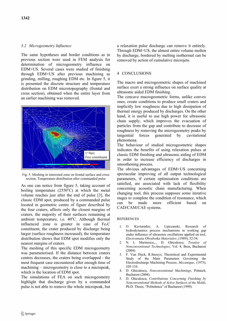
The same hypotheses and border conditions as in previous section were used in FEM analysis for determination of microgeometry influence on EDM+US. Several cases were studied of finishing through EDM+US after previous machining as grinding, milling, roughing EDM etc. In figure 5, it is presented the discrete structure and temperaturedistribution on EDM microtopography (frontal and cross section), obtained when the entire layer from an earlier machining was removed.
Fig. 5. Meshing in interested zone on frontal surface and cross section. Temperature distribution after commanded pulse
As one can notice from figure 5, taking account of boiling temperature (2550oC) at which the metal volume reaches just after the end of pulse [3], the classic EDM spot, produced by a commanded pulse located in geometric centre of figure described by the four craters, affects only the closest margins of craters, the majority of their surfaces remaining atambient temperature, i.e. 40oC. Although thermal influenced zone is greater in case of Fe3Cconstituent, the crater produced by discharge being larger (surface roughness increased), the temperature distribution shows that EDM spot modifies only the nearest margins of craters. The meshing of this specific EDM microgeometry was parameterised. If the distance between craters centres decreases, the craters being overlapped - the most frequent case encountered after enough time of machining – microgeometry is close to a micropeak, which is the location of EDM spot. The simulations of FEA on such microgeometry highlight that discharge given by a commanded pulse is not able to remove the whole micropeak, but
a relaxation pulse discharge can remove it entirely. Through EDM+US, the almost entire volume molten by discharge, bordered by melting isothermal can beremoved by action of cumulative microjets.
4 CONCLUSIONS
The macro and microgeometric shapes of machined surface exert a strong influence on surface quality at ultrasonic aided EDM finishing. The concave macrogeometric forms, unlike convex ones, create conditions to produce small craters and implicitly low roughness due to high dissipation of thermal energy produced by discharges. On the other hand, it is useful to use high power for ultrasonic chain supply, which improves the evacuation of particles from the gap and contribute to decrease of roughness by removing the microgeometry peaks by tangential forces generated by cavitational phenomena. The behaviour of studied microgeometric shapes indicates the benefits of using relaxation pulses at classic EDM finishing and ultrasonic aiding of EDM in order to increase efficiency of discharges in smoothening process. The obvious advantages of EDM+US concerning spectacular improving of all output technological parameters, if certain optimisation conditions are satisfied, are associated with lack of flexibility concerning acoustic chain manufacturing. When changing tool, this process supposes some iterative stages to complete the condition of resonance, which can be made more efficient based on CAD/CAM/CAE systems.
REFERENCES
1. O. Kavtaradze, A. Lipceanski, Research of hydrodynamics process mechanisms in working gap under influence of ultrasonic oscillations applied on tool, Electronnaia Obrabotka Materialov, (1989), 52-54.
2. N. I. Marinescu,.., D. Ghiculescu, Treatise of
Nonconventional Technologies, Vol. 8, Bren, Bucharest (2004).
3. F. Van Dijck, R.Snoeys, Theoretical and Experimental Study of the Main Parameters Governing the Electrodischarge Machining Process, Mecanique, (1975), 105-110.
4. D. Ghiculescu, Nonconventional Machinings, Printech, Bucharest (2004).
5. D. Ghiculescu, Contributions Concerning Finishing by
Nonconventional Methods of Active Surfaces of the Molds,Ph.D. Thesis, “Politehnica” of Bucharest (1999).
1
MX
XY
Z
40
318.889597.778
876.6671156
14341713
19922271
2550
JUL 1 2001
08:40:52
NODAL SOLUTION
STEP=1SUB =1
TIME=1TEMP (AVG)
SMN =40SMX =2550
ti=4 s;Fe constituent
1342
Related Documents