DOCTORAL THESIS Luleå University of Technology Department of Chemical Engineering and Geosciences Division of Process Metallurgy 2007:14|:1402-1544|: - -- 07⁄14 -- 2007:14 Influence of Green Pellet Properties on Pelletizing of Magnetite Iron Ore Seija Forsmo

Welcome message from author
This document is posted to help you gain knowledge. Please leave a comment to let me know what you think about it! Share it to your friends and learn new things together.
Transcript
DOCTORA L T H E S I S
Luleå University of TechnologyDepartment of Chemical Engineering and Geosciences
Division of Process Metallurgy
2007:14|: 1402-1544|: - -- 07⁄14 --
2007:14
Influence of Green Pellet Properties on Pelletizing of Magnetite Iron Ore
Seija Forsmo
Influence of Green Pellet Properties on Pelletizingof Magnetite Iron Ore
Seija Pirkko Elina Forsmo
Doctoral ThesisLule
Department of Chemical Engineering and GeosciencesDivision of Process Metallurgy
SE-971 87 LuleSweden
2007


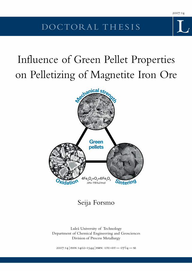
Cover illustration:
A schematic drawing visualizing the influence of green pellet properties onpelletizing of magnetite iron ore.
Mechanical strength in green pellets (sphere on top): A SEM image showingpacking of particles on the surface of a green pellet.
Oxidation (sphere to the left): A microscope image showing hematite needles in apartially oxidized green pellet.
Sintering (sphere to the right): A SEM image showing the structure in a sinteredpellet.


1
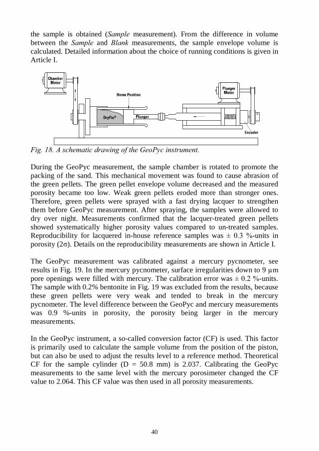
Magnetite iron ore green pellets are produced by balling moist concentrates togreen pellets, which are then dried, oxidized to hematite, sintered, cooled andtransported to steelmaking plants. The existing theory for balling is based on thecapillary theory, but its applicability under industrial balling conditions is unclear.The aim of this study has been to clarify the principal mechanisms controlling theproperties of iron ore green pellets. Special attention has been paid to studyinghow variations in raw material fineness influence green pellets behaviour duringballing, oxidation and sintering. This knowledge of the principal mechanisms isneeded to provide a sound basis for a successful process control strategy. Theapplied approach was to further develop the laboratory methods used in greenpellet characterization. Oxidation in green pellets was measured bythermogravimetry and sintering was followed by dilatometry.
A new measuring device for the characterization of green pellet strength was builtand a new measuring method for green pellet plasticity was developed. Theoptimum moisture content in balling was defined as the moisture content resultingin a given degree of plasticity in green pellets. Pellet feeds with steeper particlesize distributions required a higher moisture content in balling. Properties of greenpellets prepared from different raw materials should be compared at constantplasticity (under realistic balling conditions), not at constant moisture content, ashas been done earlier. At constant plasticity and with 0.5% bentonite binder,variations in the fineness of the magnetite concentrate did not influence the greenpellet wet strength, within the limits studied in this work. This is because in thepresence of the bentonite binder, green pellet wet strength was mainly controlledby the viscous forces of the binder liquid.
A marked degradation in green pellet mechanical strength both in wet and drystates was found in the presence of a surface-active flotation collector reagent.This loss in green pellet quality was explained by a strong attachment of airbubbles in the green pellet structure. High-speed camera images showed multi-breakage patterns due to crack propagation between the air bubbles. This explainsthe increased generation of dust observed at the pellet plant. The negative effectsof the flotation collector reagent on balling diminished during storage of the pelletfeed. The results emphasize the importance of minimizing the reagent dosages inflotation and maximizing the residence time of the pellet feed in thehomogenizing storage before balling.
When a pellet starts to oxidize, a shell of hematite is formed while the pellet coreis still magnetite. Thermal volume changes in these two phases were studied.Sintering in the magnetite phase started earlier (950
2
phase (1100 Therefore, the difference in sintering rates between the magnetiteand hematite phases was largest at around 1100oC. The sintering rate increased inboth phases with increasing fineness in the magnetite concentrate. A finer grind inthe raw material would, therefore, promote the formation of the unwanted duplexstructures with a more heavily sintered core pulling off from the shell. At constantoriginal porosity in green pellets, the oxidation rate decreased as the magnetiteconcentrate became finer, because of the enhanced sintering. However, inpractical balling, finer raw materials would necessitate the use of more water inballing, which results in an increase in green pellet porosity. These two oppositeeffects levelled out and the oxidation time became constant. Under processconditions, differences in the duplex structure would still be expected. This isbecause only partial oxidation takes place before sintering in the kiln.
Olivine, which is used as an additive in LKAB blast furnace pellets, was found toinitiate the dissociation of hematite back to magnetite already at temperatures thatcan occur during oxidation in the PH zone. The rate of dissociation was largelyinfluenced by the olivine fineness. If the dissociation temperature is exceeded, theresulting decrease in the oxidation rate increases the size of the un-oxidized coreexposed to sintering before oxidation. Also, dilatometer measurements showedopposite thermal volume changes in the oxidized hematite shell and in themagnetite core in the presence of olivine. Dissociation caused a large volumeincrease in the oxidized hematite shell, while the olivine addition furtherenhanced the sintering of the magnetite core. These mechanisms lead to increasedstructural stress between the hematite shell and the magnetite core. Thisknowledge was applied at the LKAB Svappavaara pelletizing plant. Coarsergrinding of the olivine additive resulted in a marked improvement in the low-temperature reduction strength (LTD) in pellets.
The final conclusion, then, is that excessive grinding of the pelletizing rawmaterials, both the magnetite concentrate and the additives, can cause severeproblems and step-wise changes in the oxidation and sintering mechanismswithout resulting in any additional gain in terms of green pellet mechanicalstrength. The capillary theory failed to describe the properties of wet green pelletsunder industrial balling conditions. The results also clearly point out thatcontinuous in raw material properties would cause complexfluctuations in both balling and induration.
Agglomeration; Pelletizing; Iron ore; Magnetite; Green pellets;Oxidation; Dilatation; Particle size

3
I wish to thank the Agricola Research Centre (ARC) for giving me the possibilityto perform these studies. I also wish to thank my company, Luossavaara-Kiirunavaara AB (LKAB), for encouraging me to accomplish this thesis. I havebeen met with enthusiasm and interest at LKAB. I hope I managed to fulfil atleast some of your high expectations.
My sincerest thanks go to my supervisors, Professor Bo Bj at LTU,Division of Process Metallurgy and Per-Olof Samskog, Manager StrategicResearch Projects at LKAB. You both have an extraordinary ability to find theessential questions. I am deeply grateful for your highly valuable and kind advice.I have felt very confident in working under your guidance. Per-Olof, you havebeen my boss at LKAB for 17 years. You have worked persistently through allthese years to make this research possible. You also convinced me that I wouldmanage with the doctoral studies and finally, when ARC was established, I tookthe challenge. I am most grateful for your initiative and support.
I also want to thank Professor Willis Forsling, the leader of ARC, for all theconferences: I enjoyed them. Thanks also for introducing me to the press andgiving me a chance to try a career as a movie star , I was also given theopportunity to attend the inspiring lectures of such luminaries as Professors JohnRalston, Janusz Laskowski and J
Building of the Pellet Multi Press instrument was one of the major breakthroughsin the practical laboratory work. We started by building a simple prototype, but Isoon understood that what we really needed was an accurate instrument withcomprehensive software. Building the Pellet Multi Press was teamwork at its best.Running the first samples and taking the first films was like opening Christmaspresents. Many people were involved in this development work. Special thanks goto my colleagues Anders Apelqvist and Kjell-Ove Mickelsson for their competentway of running the development project and making the dreams come true. I alsowant to thank the external companies involved: Urban Holmdahl at OptimationAB, John Erik Larsson at MBV systems AB and Thomas Nordmark, DanR -Benima.
My present supervisor, Kent Tano, General Manager Process Technology atLKAB, thank you for your encouragement and for allowing me the time to writethis thesis. It is a pleasure working with you. Thanks also to all my colleagues atLKAB R&D who have encouraged me during the studies. Special thanks go toSten-Evert Forsmo for our inspiring discussions concerning problems andpossibilities in agglomeration and for Magnus Rutfors for our discussions aboutballing in full scale. To Anders Apelqvist, I extend my sincerest thanks for the

4
numerous times you have helped me with data handling problems of variouskinds. Lena Fjellstr many thanks for your energetic and initiative work withimplementing the new knowledge of green pellet properties at LKAB. Anna-Karin Rosberg, thank you for your help with studying the behaviour of bentonitesuspensions. I also want to acknowledge Benny Andreasson, Manager MineralsProcess Technology at LKAB, for his work as a project leader during thereconstruction of the olivine grinding circuit at the LKAB Svappavaara plants.Many thanks also to Eva Alld - , Senior Process Engineer at LKAB andmy former colleague at R&D, for your co-operation and support.
I have had the pleasure to work at LKAB surrounded by glad and enthusiasticpeople. Maria Rova and Maria Johansson, many thanks for your excellent workwith micro-balling and for your efforts during the in-house training sessions.Carola Yngman, thank you for launching the new porosity measurement in dailyuse at the Metallurgical Laboratory and for preparing the polished samples.Thanks also to our summer trainee, Laura Rissanen, who was the first one to ball
with running the TGA and TMA instruments. I also wish to thank KatarinaMagnusson and Tommy Svalqvist for the laboratory work some years ago, LarsHolmstedt and Christer Lindqvist from the instrument service group and MagnusAndersson for helping with the SEM images. I have worked with so many peopleat LKAB during these years, that it is impossible to mention you all. Thanks foryour work and for your positive attitude!
Magnus Tottie, Manager DR Products at LKAB, is acknowledged for reading andcommenting on this thesis. My sincerest thanks to Mark Wilcox for correctingthe language in all my publications as well as in this thesis. By now, you alreadyknow how we use the comma in the Finnish language! Thank you also to theUniversity Printing Office for your friendly and professional help with printing ofthis book. Many thanks to Pia and Yngve at Imega Promotion for your help withthe images. To my pleasure, I have become acquainted with many people workingat LTU, at the divisions of Process Metallurgy, Chemistry, Mineral Processingand Chemical Technology. Thanks for the interesting discussions in the coffeeroom and for your practical advice during my studies.
A doctoral thesis is a long journey with both ups and downs. My dear family,Sten, Oskar and Annika, thank you for loving me as I am. Without you, therewould be nothing. My sisters Tuija and Hilkka, my brother Jouko, my dearmother Fanni and my late father Eino, I love you.
5
This thesis summarizes the following publications, referred to by Romannumerals in the text:
S.P.E. Forsmo, J.P. VuoriPowder Technology 159 (2005) 71-77.
S.P.E. ForsmoInternational Journal of Mineral Processing 75 (2005) 135-144.
S.P.E. Forsmo, A.J. Apelqvist, B.M.T. Bj -O. SamskogPowder Technology 169 (2006) 147-158.
S.P.E. Forsmo, P-O. Samskog, B.M.T. BjSubmitted to Powder Technology (Feb 2006).
S.P.E. Forsmo, S-E. Forsmo, B.M.T. Bj -O. SamskogSubmitted to Powder Technology (June 2006).
S.P.E. Forsmo, A. HInternational Journal of Mineral Processing 70 (2003) 109-122.
S.P.E. Forsmo, S-E. Forsmo, P-O. Samskog, B.M.T. BjSubmitted to Powder Technology (March 2007).
6
1. A. Apelqvist, U. Holmdahl, S.P.E. Forsmo, K-O. Mickelsson, Anordning ochfj (
), Patent accepted12 September 2006: SE 528 150 C2.
2. K-O. Mickelsson, A. Apelqvist, S.P.E. Forsmo, U. Holmdahl, Anordning ochmetod vid optisk analys av en provkropp av reducerbart j(
), Patent accepted 12 September 2006: SE 528 158 C2.
3. S.P.E. Forsmo, A. Apelqvist, K-O. Mickelsson, U. Holmdahl, Metod vid analysav en provkropp av reducerbart j (
), Patentpending submitted 3 January 2005: SE 0500018-7.
B. Bj , Professor at LTU, Division of Process Metallurgy, and P-O.Samskog, Professor at LTU, Division of Chemistry and Manager StrategicResearch Projects at LKAB, have contributed as supervisors.
J. Vuori, Researcher at Helsinki University of Technology, performed themercury pycnometer measurements used to calibrate the GeoPyc porositymeasurement, as reported in Article I.
A. Apelqvist, Research Engineer at LKAB R&D, conducted the projecting workfor construction and programming of the Pellet Multi Press measuring device(Article III). The idea of constructing a modern measuring device and themeasuring methodology was provided by S.P.E. Forsmo.
S-E. Forsmo, Senior Researcher, Specialist on oxidation metallurgy at LKABR&D, provided process knowledge in Articles V and VII.
A. H , Research Engineer at LKAB R&D, performed the pilot-plantgrinding studies of olivine as reported in Article VI. The reactivity of the olivinesamples was then evaluated by S.P.E. Forsmo.

7
...................................................9.......................................................................................11
1.2.1 Green pellet compression strength..................................................................111.2.2 Green pellet plasticity ......................................................................................171.2.3 Ballability .........................................................................................................18
........................................................................20...........................................................22
....................................................................................27
...............................................................................................................31........................................................................................................33
.......................................................................34..........................................................................................34
...............................................................................35
.....................................393.1.1 Porosity in green pellets (I)..............................................................................393.1.2 Oxidation of magnetite concentrates during storage and drying (II) ................413.1.3 Pellet Multi Press, PMP (III).............................................................................443.1.4 Green pellet compression strength and sorting by breakage pattern (III)........453.1.5 Green pellet plasticity and linearity of pressure curves (III) .............................463.1.6 High-speed camera images (III) ......................................................................47
.........................................................483.2.1 Influence of moisture content and liquid filling degree on plasticity (III)...........483.2.2 Influence of raw material fineness on plasticity (IV).........................................51
............................543.3.1 Influence of bentonite binder dosage on wet-CS (III) ......................................543.3.2 Influence of moisture content and liquid filling degree on wet-CS (III).............553.3.3 Influence of raw material fineness on wet-CS (IV)...........................................56
8
..........................................................583.4.1 Influence of moisture content and bentonite dosage on drop number (III) ......583.4.2 Influence of raw material fineness on drop number (unpublished) ..................58
.............................593.5.1 Influence of original moisture content and bentonite dosage on dry-CS .........593.5.2 Influence of raw material fineness on dry-CS..................................................60
.............................................................................................................60
...........................................................................................653.7.1 Interpretation of dilatation curves for green pellets (VII) ..................................653.7.2 Influence of raw material fineness on dilatation (VII) .......................................693.7.3 Influence of green pellet porosity on dilatation (VII).........................................69
..................................................................................713.8.1 Influence of the olivine additive fineness on the oxidation of magnetite
particles (VI) ....................................................................................................713.8.2 Interpretation of oxidation curves for green pellets (VII) ..................................733.8.3 Influence of raw material fineness on oxidation in green pellets (VII)..............783.8.4 Influence of green pellet porosity on oxidation (VII).........................................79
.............................................................................................................81
....................................................................84
..........................85
...........................86
.............87
...............................................88
..............................................89
...................................................................92
....................................................................94

9
Pelletizing of iron ore was started in the 1950s to facilitate the utilization of finelyground iron ore concentrates in steel production. Two main types of processeshave been developed, the Straight Grate and the Grate Kiln processes. In theStraight Grate process, a stationary bed of pellets is transported on an endlesstravelling grate through the drying, oxidation, sintering and cooling zones. In theGrate Kiln process, drying and most of the oxidation is accomplished in astationary pellet bed. Thereafter, pellets are loaded in a rotary kiln for sintering.This way, more homogenous induration in pellets is achieved. A flow scheme forthe Luossavaara-Kiirunavaara AB (LKAB, Sweden) Kiruna pelletizing plant(KK3) utilizing the Grate Kiln process, is shown in Fig. 1. General outlines of theprocess are given below.
Agglomeration is started by grinding and upgrading the iron ore concentrate to thedesirable chemical quality and to a particle size distribution suitable for balling.Cleaning of the magnetite ore is done by magnetic separation. The LKAB Kirunaore contains some apatite and, therefore, cleaning of the magnetite concentrate iscompleted by flotation. The magnetite concentrate slurry is then mixed withadditives and filtered. Balling is done in large balling drums using water together

10
with an external binder as a binding media. The green pellets are screened toseparate the production size fraction (9 to 16 mm in diameter) for induration. Theunder-size fraction (<9 mm) is returned to the balling drums as seeds. Therecycling loads in balling circuits are usually large, about 1.2 - 2.0 times theamount of fresh feed. The over-size fraction is usually crushed and returned to theballing drums. The production rate in one balling circuit at the KK3 pelletizingplant is typically around 180 t/h. The agglomerates are calledthey are sintered in the kiln and become
A narrow size distribution in green pellets is an important criterion for the pelletquality, because high permeability in a bed of pellets is beneficial for both thepellet production process and the subsequent reduction process in steelmaking. Inpractice, variations occur in the properties of the incoming pellet feed, likemoisture content, fineness and wettability, which result in fluctuations in thegreen pellet growth rate and size distribution. Disturbances in balling give rise toincreasing recycling loads and pulsation in the production rate of the on-sizegreen pellet fraction (surging). Excessive surging causes problems not only in theballing circuits but also in the induration machine. Disturbances in the pellet sizedistribution are regulated either mechanically, by adjusting the screen openingsfor the recycling load or for the on-size fraction, orvarying the moisture content or the binder dosage. Increasing the binder dosage isknown to decrease the green pellet growth rate, making the pellets smaller, whileincreasing the water content results in an opposite effect.
Wet green pellets are loaded on a travelling grate with a bed height of 23 cm. Thisbed of wet green pellets is transported through the drying zones, the updraftdrying (UDD) and downdraft drying (DDD) zones. After the drying zones theupper part of the pellet bed is dry and warm, around 250oC, while the bottom ofthe bed is still partly humid. The travelling time through the UDD and DDDzones is typically 6 minutes. After drying, the bed of green pellets is transportedthrough the temperate preheat zone (TPH) and the preheat zone (PH), where themain part of magnetite oxidation takes place. The gas temperature at the end ofthe PH zone is around 1150 to 1250oC. The gas flow rate is in the order of 6 m/sand the oxygen content of the incoming gas is 16 to 18%. The travelling timethrough the TPH and PH zones is 6 to 7 minutes. During this time, the upper partof the pellet bed is heated up to the gas temperature, while the bottom of the pelletbed barely reaches 1000oC. After passing through the PH zone the pellets aretransferred to a rotating kiln and sintered at around 1250oC. Little or no oxidationtakes place in the kiln, due to the high temperature. Even some dissociation ofhematite back to magnetite can occur. Final oxidation of the sintered pellets takesplace in the annular cooler. Thereafter, the pellets are ready for transportation tosteelmaking plants.
11
1.2.1 Green pellet compression strength
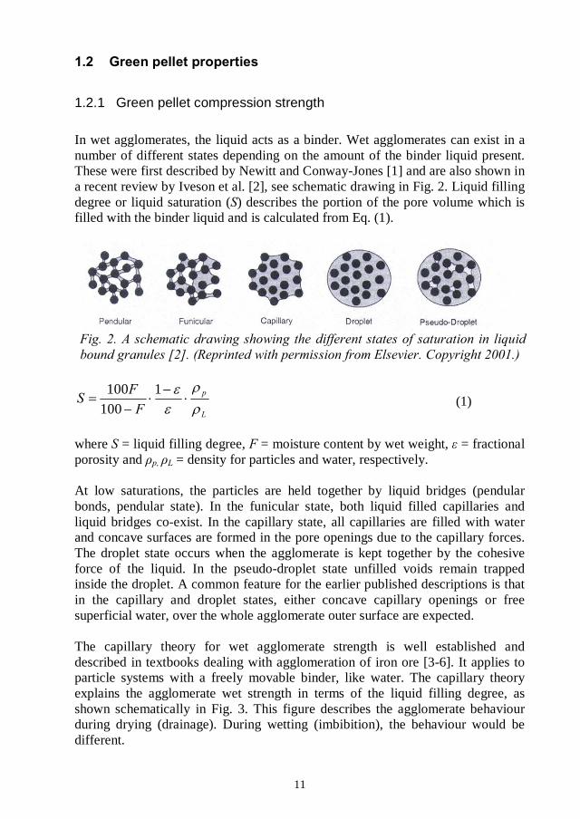
In wet agglomerates, the liquid acts as a binder. Wet agglomerates can exist in anumber of different states depending on the amount of the binder liquid present.These were first described by Newitt and Conway-Jones [1] and are also shown ina recent review by Iveson et al. [2], see schematic drawing in Fig. 2. Liquid fillingdegree or liquid saturation ( ) describes the portion of the pore volume which isfilled with the binder liquid and is calculated from Eq. (1).
1100100
(1)
where = liquid filling degree, = moisture content by wet weight, = fractionalporosity and = density for particles and water, respectively.
At low saturations, the particles are held together by liquid bridges (pendularbonds, pendular state). In the funicular state, both liquid filled capillaries andliquid bridges co-exist. In the capillary state, all capillaries are filled with waterand concave surfaces are formed in the pore openings due to the capillary forces.The droplet state occurs when the agglomerate is kept together by the cohesiveforce of the liquid. In the pseudo-droplet state unfilled voids remain trappedinside the droplet. A common feature for the earlier published descriptions is thatin the capillary and droplet states, either concave capillary openings or freesuperficial water, over the whole agglomerate outer surface are expected.
The capillary theory for wet agglomerate strength is well established anddescribed in textbooks dealing with agglomeration of iron ore [3-6]. It applies toparticle systems with a freely movable binder, like water. The capillary theoryexplains the agglomerate wet strength in terms of the liquid filling degree, asshown schematically in Fig. 3. This figure describes the agglomerate behaviourduring drying (drainage). During wetting (imbibition), the behaviour would bedifferent.

12
According to the capillary theory, the agglomerate wet strength reaches amaximum at the capillary state. This takes place at around 90% liquid fillingdegree. The agglomerate strength at this point is given by the so called Rumpfequation, Eq. (2) [7]. It states that the tensile strength of a wet agglomerateincreases with decreasing porosity and particle size and with increasing surfacetension. Complete wetting is necessary for fully developed capillary forces.
cos11
(2)
Where = green pellet wet tensile strength due to the capillary forces, =constant, = fractional porosity, = liquid surface tension, = average particlesize, = liquid-solid contact angle.
The capillary forces are much stronger than the pendular bonds. The agglomeratestrength with fully developed liquid bridges (at = 30%) is only about one thirdof the maximum strength. In the funicular state, where binding takes place byboth the pendular bonds and the capillary forces, the agglomerate strength can beestimated from the relative amount of filled capillaries. At =100%, floodingtakes place and the agglomerate deforms under its own weight.
Recently, Iveson et al. [2] reviewed the nucleation, growth and breakagephenomena in agitated wet granulation processes. The Rumpf equation (Eq. 2)has been found to over-predict the agglomerate strength. For coarse particulatesystems, the over-prediction has been explained by crack growth along pore
13
structures [2]. For fine particulate systems (dicalcium phosphate, 21diameter), the over-prediction takes place because the maximum strength hasbeen found to occur already at 20 to 30% filling degree [8]. At higher liquidfilling degrees the strength decreases rapidly. This is explained by a difference inthe main binding force. In fine particle systems, inter-particle friction forcesdominate over the capillary forces [2,9]. As the liquid filling degree increases, thelubricating effect of the liquid layer between particles reduces the frictional forcesand the agglomerate becomes weaker. In coarse particle systems, the inter-particlefriction forces are considered to be insignificant and the capillary forces prevail.
The influence of surface tension on wet agglomerate strength according to Eq. (2)has been verified by balling iron ore with water-alcohol mixtures [1,6(Fig. 72)].The agglomerate wet strength decreased with decreasing surface tension in thebinder liquid. A similar effect was seen by Kristensen et al. [9], who studied thestrength in agglomerates prepared from lactose, dicalcium phosphate and glassspheres with an aqueous polymer solution as a binder ( 47 mN/m).
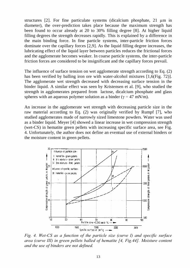
An increase in the agglomerate wet strength with decreasing particle size in theraw material according to Eq. (2) was originally verified by Rumpf [7], whostudied agglomerates made of narrowly sized limestone powders. Water was usedas a binder liquid. Meyer [4] showed a linear increase in wet compression strength(wet-CS) in hematite green pellets with increasing specific surface area, see Fig.4. Unfortunately, the author does not define an eventual use of external binders orthe moisture content in green pellets.

14
Urich and Han [10] showed an increase in wet-CS of hematite green pellets withincreasing raw material fineness, see Fig. 5. The green pellets were balled at aconstant moisture content and with 0.5% bentonite binder. The variation infineness was very large, from 45 to 99% -44 much larger than normal processvariations expected in a pelletizing plant. When looking at the whole measuringrange in fineness, the increase in wet-CS with increasing fineness is clear.However, in the midrange, near to more common fineness in iron ore pellet feeds(between 65 and 90% -44
R2 = 0.97
0.0
1.0
2.0
3.0
4.0
0 10 20 30 40 50 60 70 80 90 100
% passing by screening
Wet
-CS
,daN
/pel
let
-20 -44
Tapia et al. [11] found that green pellet wet strength increased from 0.64 to 1.76daN/pellet when the fineness of the magnetite concentrate raw material wasincreased from 79 to 100% -38 cm2/g in Blaine). As theraw material became finer, the moisture content in green pellets decreased from8.5 to 7.0%. The authors do not mention possible use of binders in balling.
The dependency of pellet wet-CS on porosity according to Eq. (2) has beenexperimentally shown by preparing agglomerates from silica sand [1] and glassspheres [6, Fig.73]. No experimental data on iron ore green pellets specifically,was found. However, wide particle size distributions are claimed to lead tostronger agglomerates [2,3-6,12], because packing of such materials tends toresult in lower porosity. When large (L) and small (S) particles are mixed indifferent proportions, a porosity minimum occurs when the mixture containsabout two thirds of the large particles, see Fig. 6 [13]. The larger the sizedifference between the large and small particles, the more distinct becomes theminimum in porosity. At the minimum porosity, the mixing ratio is such that theamount of small particles is just enough to fill the spaces formed between thelarge particles. If the amount of small particles is smaller, unfilled spaces remain.If the amount of small particles becomes larger, they start disturbing the packing

15
of the large particles and the packing pattern becomes one of large particles beingpacked in a matrix of small particles.
No experimental studies to validate the dependency of agglomerate wet strengthon variations in the liquid-solid contact angle in Eq. (2) were found. This isprobably because in practice, it is difficult to vary the contact angle independentlywithout influencing the surface tension. Complete wetting has generally beenassumed ( = 0 cos = 1). However, Iveson et al. [14,15] report contactangles from 30 to 70 gglomeration of ironore concentrates cleaned by flotation has been recognized as a problem. Iwasakiet al. [16] found that balling of iron ore concentrates in the presence of a fatty acidflotation collector reagent resulted in weaker green pellets both in wet and drystates. They found that an addition of activated carbon effectively restored thegreen pellet properties. Gustafsson and Adolfsson [17] also report that balling offlotated pellet feeds resulted in weaker green pellets (lower drop number),increased circulating loads in the balling circuits and increased generation of finesduring induration. The negative effects were explained by a combination ofdecreased surface tension in the water phase and by adsorption of the collectorreagent on magnetite. The amount of rest reagent on magnetite was analyzed andvaried between 10 and 30 g/t. The authors conclude that the scope of problems inballing decreased when the temperature in flotation was increased.
The Rumpf equation (Eq. 2) describes, strictly speaking, the strength ofagglomerates. The measurement of tensile strength is, however, very time-consuming and cannot be applied to a large number of pellets in a similar manner

16
as is applicable in the compression strength measurement. The compressionstrength is always larger than the tensile strength, because the compression forceneeds to overcome the friction between particles [7]. Rumpf [7] found a non-linear relationship between these two forces. Ball et al. [3, p.262] suggest that thecompression strength should be calculated by dividing the compression force bythe cross-section area of the pellet. Other writers claim that this kind ofcalculation is not scientifically valid, because the pellet is exposed to a point load.Further, during compression, a small variable portion of the pellet is oftensquashed flat at the point of contact forming a flat platform which distributes theload [7, in prepared discussion]. A true point contact no longer exists and a widescatter in pressure readings can result from relatively small variations in localpellet topography. This problematic issue is generally solved by using a screenedsize fraction of green pellets in the compression strength measurement and byexpressing the compression strength in daN/pellet [4, p.80]. This approach is usedat LKAB, too. In large-scale iron ore pelletization, wet-CS above 1 daN/pellet anddry-CS above 3 daN/pellet are commonly considered satisfactory [3,4].
As mentioned earlier, the capillary theory was developed for particle systems withfreely movable binders, like water, and viscosity effects are not included in thismodel. Today, viscous binders are used in iron ore pelletization. A large variety ofbinders have been tested [18]. Their positive effect on green pellet quality andpelletizing capacity in the sintering machine is well known. The most commonbinder is the bentonite clay. The amount of bentonite added is typically between0.5 and 0.7%. Bentonite swells when mixed with water and increases the viscosityof the water phase. The influence of bentonite binder on the green pellet wet-CSand dry-CS, according to Meyer [4], is shown in Fig. 7. In magnetite greenpellets, both wet-CS and dry-CS increased with increasing bentonite dosage. Themechanisms for the increase in wet-CS have not been discussed in earlierliterature. The favourable effect of bentonite for dry-CS is explained by bentonitebeing concentrated in particle contact points during drying. During the finalevaporation of the bentonite gel, solid mortar bridges are formed with increasingdry-CS as a result [4, p. 112]. The dehydration of bentonite gel is also claimed tobe accompanied by a shrinkage which increases the adhesion forces [4, p.36].According to Pietsch [6], the rate of drying influences the distribution of bentoniteflakes in green pellets and dry-CS. Kawatra and Ripke [19,20] have found thatbentonite clays form fibrous structures under compressive shear, which results inan appreciable increase in green pellet strength.
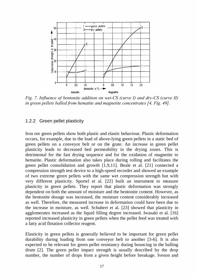
17
1.2.2 Green pellet plasticity
Iron ore green pellets show both plastic and elastic behaviour. Plastic deformationoccurs, for example, due to the load of above-lying green pellets in a static bed ofgreen pellets on a conveyor belt or on the grate. An increase in green pelletplasticity leads to decreased bed permeability in the drying zones. This isdetrimental for the fast drying sequence and for the oxidation of magnetite tohematite. Plastic deformation also takes place during rolling and facilitates thegreen pellet consolidation and growth [1,9,11]. Beale et al. [21] connected acompression strength test device to a high-speed recorder and showed an exampleof two extreme green pellets with the same wet compression strength but withvery different plasticity. Sportel et al. [22] built an instrument to measureplasticity in green pellets. They report that plastic deformation was stronglydependent on both the amount of moisture and the bentonite content. However, asthe bentonite dosage was increased, the moisture content considerably increasedas well. Therefore, the measured increase in deformation could have been due tothe increase in moisture, as well. Schubert et al. [23] showed that plasticity inagglomerates increased as the liquid filling degree increased. Iwasaki et al. [16]reported increased plasticity in green pellets when the pellet feed was treated witha fatty acid flotation collector reagent.
Elasticity in green pellets is generally believed to be important for green pelletdurability during loading from one conveyor belt to another [3-6]. It is alsoexpected to be relevant for green pellet resistancy during bouncing in the ballingdrum [2]. The green pellet impact strength is usually described by the dropnumber, the number of drops from a given height before breakage. Iveson and

18
Litster [24] found that increasing binder viscosity increased the extent of elasticdeformation in wet granules made of glass spheres. This is in good agreementwith iron ore green pellet behaviour, because the drop number is known toincrease with the amount of bentonite added [4, p.114].
1.2.3 Ballability
Ballability is defined as the ability of particulate matter to form pellets [6, p. 12].The main parameters for good ballability in iron ore pellet feeds are the finenessof the raw material, the moisture content in balling, binder dosage and goodwetting of the particles. Raw material fineness in balling is commonly expressedusing the specific surface area measured with the Blaine permeability method.The Blaine apparatus and measuring principle are shown by e.g. Ball et al. [3,p.270]. The Blaine values are expressed in cm2/g. At LKAB, the specific surfacearea is measured with a similar permeability method described by Svensson [25].It is called as the KTH-surface area and the results are given in cm2/cm3. TheKTH-surface area and Blaine values show a linear relationship [26]. KTH-surfacearea values can be converted to Blaine by dividing by particle density (typically5.12 g/cm3 for LKAB magnetite concentrates).
Meyer [4, Fig.46] collected data on running conditions from sixteen differentpelletizing plants regarding raw material fineness. He found that the relativeuniformity in Blaine values was striking; all pellet feeds showed Blaine valuesbetween 1,500 and 2,000 cm2/g. The screening fraction %-45 m underwentgreater variations (70 to 95%). At LKAB, the minimum specific surface area forgood ballability is considered to be somewhere around 9,500 cm2/cm3 (1,900cm2/g). This figure is based on practical experience, but the exact behaviour inballing with coarser raw materials is not well documented. Reasons for deviatingballing behaviour are difficult to verify in full production scale because of thecomplex nature of the balling process.
Each raw material has an optimum moisture content for balling [3-6]. It dependson the particle size and the particle size distribution, inner porosity in particles,surface roughness and wettability of the solids [6, p.167]. According to Meyer [4,p.105], these parameters often overlap in a complex manner and, therefore, theoptimum moisture content cannot be clearly defined. The optimum moisturecontent increases with increasing fineness. Meyer [4] showed the influence ofmoisture content on wet-CS and drop number in green pellets prepared frommagnetite concentrates with varying fineness, see Fig. 8. Wet-CS showed a broadmaximum and the maximum value became higher when the raw material becamefiner. The maximum wet-CS values were throughout very high, 2.3 daN/pellet forthe coarsest material (1,100 cm2/g, approx. 5,600 cm2/cm3) and 3.8 daN/pellet forthe finest raw material (3,370 cm2/g, approx. 17,300 cm2/cm3). Eventual use of
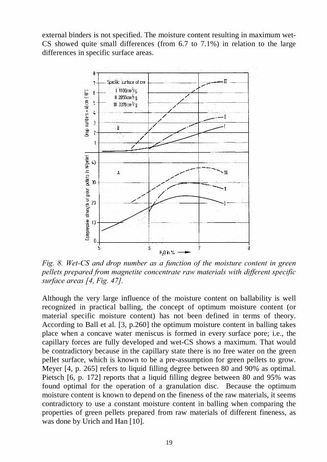
19
external binders is not specified. The moisture content resulting in maximum wet-CS showed quite small differences (from 6.7 to 7.1%) in relation to the largedifferences in specific surface areas.
Although the very large influence of the moisture content on ballability is wellrecognized in practical balling, the concept of optimum moisture content (ormaterial specific moisture content) has not been defined in terms of theory.According to Ball et al. [3, p.260] the optimum moisture content in balling takesplace when a concave water meniscus is formed in every surface pore; i.e., thecapillary forces are fully developed and wet-CS shows a maximum. That wouldbe contradictory because in the capillary state there is no free water on the greenpellet surface, which is known to be a pre-assumption for green pellets to grow.Meyer [4, p. 265] refers to liquid filling degree between 80 and 90% as optimal.Pietsch [6, p. 172] reports that a liquid filling degree between 80 and 95% wasfound optimal for the operation of a granulation disc. Because the optimummoisture content is known to depend on the fineness of the raw materials, it seemscontradictory to use a constant moisture content in balling when comparing theproperties of green pellets prepared from raw materials of different fineness, aswas done by Urich and Han [10].

20
Both the moisture content and the bentonite dosage are well known to influencethe green pellet growth rate [e.g. 27]. Increasing the moisture content increasesthe green pellet growth rate and increasing the bentonite dosage has an oppositeeffect, see Fig. 9. The figure shows the large sensitivity of pellet growth rate tovariations in the moisture content. Small adjustments can be made by changingthe bentonite dosage. Sastry and Fuerstenau [27] introduced the concept ofballability index ( ), shown in Eq. (3). The ballability index considers the waterbalance in terms of decreases with increasingadditions of bentonite.
(3)
wheretotal mass of moisture, y one gram binderand B = bentonite dosage.
02468
1012141618
9.8 10.0 10.2 10.4 10.6 10.8 11.0
Moisture content, %
Ave
rage
gre
en
pe
llet
dia
me
ter,
mm
Without bentonite 0.5% bentonite
0.75% bentonite 1.0% bentonite
0.0%
0.5%0.75%1.0%
Oxidation of magnetite to hematite is a highly exothermic reaction (Eq. 4).
4 FeO Fe2O3 + O2 = 6 Fe2O3 -119 kJ/mol magnetite (4)
Oxidation of magnetite concentrate particles with increasing temperature showsthree main steps (see TGA curves later in Fig. 69). The first oxidation step runs at

21
low temperatures, below 400oC. Thereafter, the second oxidation step starts andleads to complete oxidation between 900 and 1100oC [28]. The third step startswhen dissociation of hematite back to magnetite is initiated. According to thephase diagram [29, Fig. 3.6], dissociation starts at 1457 in O2 and at 1392air. The dissociation of hematite has been reported to start at lower temperatureswhen basic additives are present [4, p.154]. This was first explained by atemperature rise inside pellets due to the exothermic heat of formation of calciumferrites and their additional melting heat, which would bring about an over-heating in the pellet core to temperatures exceeding 1400showed, however, that the formation of solid solutions with the hematite phaseactivates the dissociation of hematite back to magnetite several hundred degreescentigrade earlier than in a pure hematite phase. Of the studied additives, thestarting temperature for dissociation was lowest with MgO additions [31].
In view of current knowledge, the low-temperature oxidation of colloidalmagnetite particles produces -hematite, also called maghemite, as the onlyoxidation product at temperatures below about 500oC [32,33]. Like magnetite, -hematite is magnetic. Heating above 500oC converts the -hematite to -hematite.In the case of larger magnetite particles, it is now generally agreed that a step-wise oxidation mechanism takes place [32,34,35]. Low-temperature oxidationstarts by initial formation of -hematite followed by a spontaneous nucleation of
-hematite arising from increasing structural stress in the -hematite phase. Afternucleation, the low-temperature oxidation proceeds with -hematite as the onlyoxidation product.
Oxidation of magnetite particles to -hematite at intermediate temperatures startsby the formation of hematite needles (lamellae) at particle surfaces. This isbecause oxidation starts parallel to the closed packed planes in magnetite and the{111} planes in magnetite are transformed to {1000} planes in hematite [36,37].The distance between closed packed planes is greater in hematite than inmagnetite (0.687 and 0.485 nm, respectively), which implies that perpendiculargrowth is halted because of a shortage of space. The needles grow fast in lengthbut widen slowly. According to Bentell and Mathisson [37], the hematite needlesare formed due to diffusion of Fe2+/Fe3+ ions in the magnetite phase. The diffusionrate can be affected by dislocations, vacancies and impurities, i.e. the properties ofthe magnetite mineral [3, p.325]. At the particle surfaces, Fe2+ ions lose oneelectron to surface adsorbed oxygen, so that Fe3+ and O2
- ions are formed. TheFe3+ ions return to most favourable sites of the hematite crystal being formed,while diffusion of O2
- ions is only possible to a limited extent along the hematite-magnetite crystal boundaries [37]. When the magnetite particles become coveredby a thin layer of hematite, the oxidation rate decreases. This is because diffusionin the hematite phase is limited by the high stoichiometry in the hematitestructure. At higher temperatures, fast diffusion through the hematite shellbecomes possible. At higher temperatures structural stress due to the volumetricchanges caused by oxidation is expected to open up the structure for the diffusion

22
of oxygen, as well. This increases the driving force of oxidation and allows forfurther growth of the lamellae [37].
Niiniskorpi [38] found differences in the oxidation pattern in magnetite particlesat different process stages. Oxidation to hematite lamellae was favoured duringoxidation in the TPH-zone and in the cooler, while oxidation to single hematitecrystals was favoured in the kiln.
Monsen [39] studied the kinetics in oxidation of Sydvaranger magnetite insamples with particle sizes between 74 and 100blown together with air into a hot reactor and then purged out after up to 60seconds oxidation time. The studied temperature range was between 400 and850 s was found.The rate of oxidation followed the parabolic rate law, except during an initialperiod of around ten seconds, see Fig. 10. The maximum conversion was 42%after 60 seconds at 850
For the pelletizing process, oxidation at high temperatures, above 900main interest. More than two thirds of the total energy needed for sintering at theLKAB pelletizing plants comes from the oxidation reaction. High-temperatureoxidation of magnetite concentrate particles can essentially differ fromthe behaviour registered for clean powders, because in pellets the magnetiteparticles are in near contact with the bentonite binder and the additives mixed in
23
pellet feeds. In pellets, porosity influences the diffusion rate of oxygen and theoxidation rate can be retarded by both sintering and slag formation. Therefore, aseparate literature overview covering the oxidation and sintering in pellets isprovided.
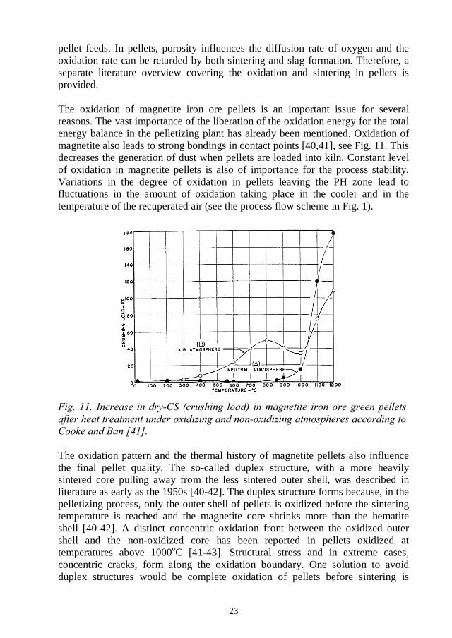
The oxidation of magnetite iron ore pellets is an important issue for severalreasons. The vast importance of the liberation of the oxidation energy for the totalenergy balance in the pelletizing plant has already been mentioned. Oxidation ofmagnetite also leads to strong bondings in contact points [40,41], see Fig. 11. Thisdecreases the generation of dust when pellets are loaded into kiln. Constant levelof oxidation in magnetite pellets is also of importance for the process stability.Variations in the degree of oxidation in pellets leaving the PH zone lead tofluctuations in the amount of oxidation taking place in the cooler and in thetemperature of the recuperated air (see the process flow scheme in Fig. 1).
The oxidation pattern and the thermal history of magnetite pellets also influencethe final pellet quality. The so-called duplex structure, with a more heavilysintered core pulling away from the less sintered outer shell, was described inliterature as early as the 1950s [40-42]. The duplex structure forms because, in thepelletizing process, only the outer shell of pellets is oxidized before the sinteringtemperature is reached and the magnetite core shrinks more than the hematiteshell [40-42]. A distinct concentric oxidation front between the oxidized outershell and the non-oxidized core has been reported in pellets oxidized attemperatures above 1000oC [41-43]. Structural stress and in extreme cases,concentric cracks, form along the oxidation boundary. One solution to avoidduplex structures would be complete oxidation of pellets before sintering is

24
started, as suggested by Cooke and Stowasser [42]. They called this processdouble firing. Ilmoni and Uggla [40] found that the degree of oxidation needs tobe at least 80% in pellets leaving the PH zone to get acceptable strength in pelletsafter firing. According to Haas et al. [45], enriching the oxidizing gas in the PHzone to around 30% oxygen and controlling the speed of temperature rise in thePH zone to be below 150oC/min would improve the pellet quality.
Several comprehensive studies on oxidation mechanisms in magnetite iron orepellets have been published starting from the early 1950s [28,40-49]. Theinfluence of partial pressure of oxygen [28,43], pellet porosity [43], pellet size[28,40,45], magnetite concentrate fineness [43] and calcining [49] on theoxidation of pellets has been described. Oxidation of the outer shell of pellets isfast and controlled by the rate of the chemical reaction [43,46]. After the fastsuperficial oxidation, the oxidation rate is claimed to be controlled by thediffusion rate of oxygen through the growing product layer [43,46,50]. Someexamples of oxidation curves measured by Zetterstr 8] for pellets preparedfrom Scrub Oak magnetite and oxidized isothermally in air are shown in Fig. 12.
.
Zetterstr 28] found that the time needed for oxidation is largely dependent onthe partial pressure of oxygen, which is the driving force for diffusion. The time
25
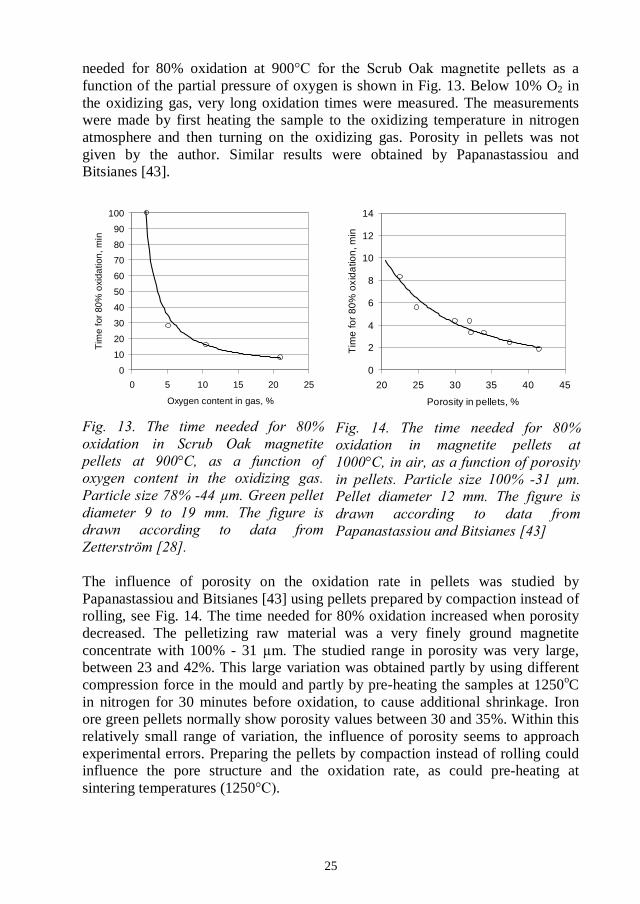
needed for 80% oxidation at 900 as afunction of the partial pressure of oxygen is shown in Fig. 13. Below 10% O2 inthe oxidizing gas, very long oxidation times were measured. The measurementswere made by first heating the sample to the oxidizing temperature in nitrogenatmosphere and then turning on the oxidizing gas. Porosity in pellets was notgiven by the author. Similar results were obtained by Papanastassiou andBitsianes [43].
0
10
20
30
40
50
60
70
80
90
100
0 5 10 15 20 25
Oxygen content in gas, %
Tim
efo
r80
%o
xida
tion
,min
0
2
4
6
8
10
12
14
20 25 30 35 40 45
Porosity in pellets, %
Tim
efo
r80
%ox
ida
tion
,min
The influence of porosity on the oxidation rate in pellets was studied byPapanastassiou and Bitsianes [43] using pellets prepared by compaction instead ofrolling, see Fig. 14. The time needed for 80% oxidation increased when porositydecreased. The pelletizing raw material was a very finely ground magnetiteconcentrate with 100% - 31 The studied range in porosity was very large,between 23 and 42%. This large variation was obtained partly by using differentcompression force in the mould and partly by pre-heating the samples at 1250oCin nitrogen for 30 minutes before oxidation, to cause additional shrinkage. Ironore green pellets normally show porosity values between 30 and 35%. Within thisrelatively small range of variation, the influence of porosity seems to approachexperimental errors. Preparing the pellets by compaction instead of rolling couldinfluence the pore structure and the oxidation rate, as could pre-heating atsintering temperatures (1250 .

26
The time needed to obtain a given degree of oxidation in pellets has been found tobe directly proportional to the square of the diameter of the pellet [40,45]. If thepellet size is doubled, the oxidation time would be four times longer. Theseresults are based on isothermal oxidation measurements at quite hightemperatures, at 1230oxidation reaction could also be retarded by dissociation [30,31].
Very limited data regarding the influence of magnetite concentrate fineness on theoxidation rate in pellets was found in earlier literature. Zetterstr 28] showedoxidation curves for pellets balled from two different magnetite concentrates,artificially prepared to similar fineness. Only oxidation at 700oC was measured.The conclusion was that particle size accounts only for a part of the measureddifference in oxidation rates. Porosity in the studied green pellets was notmentioned.
Although the oxidation and sintering phenomena show complex interdependencyduring the formation of duplex structures, only a few dilatometer studies onmagnetite iron ore pellets have been published [28,40,45]. Contraction in pelletsduring oxidation [28,45] and incipient sintering at 900oC have been reported[40,45]. Ilmoni and Uggla [40] showed that at 1230phase was about 1.4 times greater than in the hematite phase. They also showedthat shrinkage in pellets increased with increasing specific surface area in themagnetite raw material. The degree of shrinkage was dependent on the time thepellet was exposed to sintering temperatures.
Linear thermal expansion for both magnetite and hematite crystals during heatingfrom 20 to 400 has been measured to be 0.4% [51]. Linear thermal expansionin magnetite during heating from 20 to 1000[51]. For hematite, values for thermal expansion at temperatures above 400were not found.
Most of the earlier work has been directed towards measuring the isothermaloxidation rate in pellets. Some principally different experimental set-ups havebeen applied which could influence the obtained results. One method is to allowthe sample to reach the desired isothermal temperature under non-oxidizingatmosphere before the oxygen containing gas, most often air, is turned on[28,43,47]. This method is truly isothermal but there are two drawbacks, both ofwhich tend to decrease the measured oxidation rate. First, the oxidizing gas isdiluted by the inert gas in the beginning of the oxidation experiment [26] and theinitial rate of oxidation becomes too low. Secondly, if this method is used attemperatures above 800oC, sintering would take place before oxidation andsuppress the oxidation rate. Also, the degree of sintering would be dependent onthe time used for pre-heating. Differences in the pre-heating time would make theoxidation results non-comparable. Another method that has been used is to pre-heat the sample at around 500oC before measuring the oxidation rate [45].This was regarded as justified, because the extent of oxidation in temperatures

27
below 500oC was considered too small to be relevant for the subsequentpelletizing process. However, in magnetite pellet concentrates of typicalpelletizing fineness as much as 10 to 25% of all oxidation can take place alreadyat temperatures below 400oC [28]. Finally, if no heat pre-treatment is done beforeregistering the oxidation weight gain [46], any loss of weight, like calcining andespecially the dehydration of the bentonite binder, would take place during theoxidation period and diminish the measured weight gain. Bentonite contains bothfree water (about 10%) and structurally bound water (about 10%), which is lostbetween 500 and 800oC.
Because of the largely exothermic nature of the oxidation reaction (Eq. 4), atemperature rise inside the pellet during oxidation can be expected. Temperaturedifferences between the pellet outer surface and the pellet core of 100oC inmagnitude have been reported [40,42,48]. Papanastassiou and Bitsianes [43]pointed out that pellets oxidizing in a bed of similarly-reacting pellets faceanother thermal environment than a single pellet being oxidized in a combustiontube furnace. In the combustion tube furnace, if the pellet surface temperaturerises through oxidation, it can lose heat to the gas stream which acts as a heat sinkat the furnace operating temperature. In a bed of pellets, a similar situation wouldraise the gas temperature.
The properties of iron ore green pellets are of vast importance for the pelletizingprocess, as visualized in Fig. 15. Green pellet properties not only influence theproductivity in balling through the pellets mechanical strength, but also influencethe oxidation and sintering mechanisms during induration.
The existing theory to describe the strength of wet iron ore green pellets is basedon the capillary theory. It describes the interaction between the raw materialproperties (like fineness) and the balling conditions (like moisture content). Theraw material properties originate from the concentrating plant while the ballingconditions are regulated at the pelletizing plant. For practical process control, themutual interdependency of these parameters needs to be understood. Theapplicability of the capillary theory on balling under industrial conditions isunclear. This uncertainty in the prevailing binding mechanisms tends to restrictfurther process development at both the pelletizing and the concentrating plants,because the consequences of process changes for agglomeration are difficult topredict. A number of full-scale and pot grate tests have been carried out at LKABduring the past years to quantify the influence of raw material parameters on theagglomeration process. The results have, however, been unclear, probablybecause of several contemporary changes. Also the available measuring methodsfor the characterization of green pellet properties have been insufficient.

28
One of the key parameters influencing the behaviour of iron ore green pellets isthe raw material fineness. In the capillary theory, the raw material fineness isconsidered as a parameter controlling the green pellet mechanical strength. In thecase of magnetite iron ore concentrates, however, raw material fineness influencesthe oxidation and sintering mechanisms, as well. Raw material fineness caninfluence the oxidation and sintering patterns either directly through a change inthe actual particle size, or, indirectly through variations in green pellet porosity.The capillary theory claims that wet agglomerates should be strongest when theporosity in green pellets is low, but low porosity would not be beneficial for theoxidation process. These interactions are not sufficiently well understood andneeded to be studied further.
The aim of this study has been to clarify the principal mechanisms controllingiron ore green pellet behaviour during balling, oxidation and sintering whenvariations in raw material properties and balling conditions occur. Special

29
attention has been paid to variations in the raw material fineness. The approachchosen in this study was to further develop the laboratory methods used in greenpellet characterization. In laboratory, the experiments can be done under well-controlled and repeatable conditions. This kind of knowledge of the principalmechanisms provides a sound basis for a successful process control strategy.
The scope of the seven articles included in this thesis is outlined in Fig. 15.Porosity in green pellets is a common parameter for balling, oxidation andsintering. The existing porosity measurement needed to be further improved(Article I). The existing instrument that was used to measure the green pelletcompression strength was inaccurate and the results were operator-dependent.Therefore, a new modern measuring instrument was developed and newparameters for the characterization of green pellets were introduced (Article III).Thereafter, binding mechanisms in wet green pellets as a function of the moisturecontent and the bentonite binder dosage were studied (Article III). Also theinfluence of raw material fineness and additions of a flotation collector reagent ongreen pellet strength were studied (Articles IV and V).
The oxidation studies were started by examining in detail the non-isothermalTGA curves for magnetite particles (Article II). Thereafter, the influence of thefineness of the olivine additive on oxidation of magnetite particles was studied(Article VI). And finally, mechanisms in oxidation and sintering of green pelletsin relation to variations in magnetite concentrate fineness and green pelletporosity, were studied (Article VII).

30

31
Magnetite pellet concentrate samples were collected from the LKAB(Luossavaara-Kiirunavaara AB, Sweden) Malmberget (MPC), Svappavaara (SPC)and Kiruna (KPC) concentrating plants. They typically contain 71% Fe, 23% Fe2+
and 0.6% SiO2. MPC is produced from the Malmberget magnetite ore and groundin ball mills in three stages, in open grinding circuits. SPC is produced using acertain fraction of the magnetite ore from the Kiruna mine. The last grinding stepat Svappavaara is done in a pebble mill connected to a spiral classifier. KPC isproduced from the Kiruna ore and ground in closed circuit with hydro cyclonesand, therefore, the particle size distribution is narrower than that of MPC andSPC. To reach the target of around 10,000 cm2/cm3 in specific surface area in thepellet feed, MPC needs to be ground to 68% -45 -45KPC to 85%-45layout, but also because less fines is created from the Kiruna ore compared to theMalmberget ore [unpublished data]. The moisture content in balling is typically8.0% for MPC, 9.0% for SPC and 9.2% for KPC.
To study the influence of variations in magnetite concentrate fineness on greenpellet properties [Articles IV and VII], five MPC samples (MPC-1 to MPC-5) andsix SPC samples (SPC-1 to SPC-6) were collected from the concentrating plantsby varying the feed rate into the grinding mills. The sampling was spread over aperiod of a few weeks so that the samples would also reflect some of the normalvariations in ore quality. The magnetite concentrate from Kiruna was not includedin these studies, because the influence of the flotation collector reagent (a surface-active agent) on the agglomeration system was not known when this work wasstarted. Instead, the influence of additions of the flotation collector reagent wasstudied separately (Article V). Particle size data obtained by screening andcyclosizer and the specific surface areas according to Svensson [25] for each ofthe materials are shown in Table 1. The samples are arranged in order ofincreasing %-45MPC-2 and SPC-3, represent typical process finenesses.
The SPC-3 sample was used to study the influence of moisture content and thebinder dosage on green pellet properties [Article III] as well as in the methoddevelopment work done to improve the reproducibility in the porositymeasurement [Article I]. A typical KPC sample was used to study the influence ofthe flotation collector reagent on green pellet properties [Article V], becauseflotation is only applied at the LKAB Kiruna concentrating plants. Particle sizingdata for this KPC sample is given in Table 1. The KPC and MPC samples, whichwere used to study the oxidation of magnetite concentrate powders during storageand drying [Article II], were of typical process fineness.

32
Spec. surface Cyklosizer Screeningarea -7 -13 -26 -45 -63 -90
cm2/cm3% % % % % %
MPC-1 9491 16.5 29.2 49.0 66.1 77.5 88.5MPC-2 10038 17.2 31.3 52.2 68.8 80.3 90.5MPC-3 10774 18.8 34.1 55.8 71.7 81.7 91.3MPC-4 11606 20.8 36.5 58.5 75.4 84.9 93.3MPC-5 12386 20.3 37.0 59.9 77.2 86.7 94.7
SPC-1 9404 16.1 30.0 52.3 71.4 82.0 90.3SPC-2 9747 16.4 31.1 54.4 74.9 86.0 94.2SPC-3 10089 17.2 31.1 53.4 75.2 84.7 93.4SPC-4 10184 16.0 30.4 53.6 75.3 85.9 94.5SPC-5 10450 17.2 32.8 57.7 78.1 88.0 95.5SPC-6 11000 18.5 34.5 59.9 80.1 90.0 96.3
KPC 9918 17.4 34.2 60.9 84.4 94.0 98.5
The influence of olivine fineness on the oxidation of magnetite particles wasstudied by mixing olivine ( ) with the SPC-3 magnetiteconcentrate [Article VI]. Thehigh magnesium content, typically 48% MgO, 42% SiO2 and 5% Fe. The olivinelumps were first crushed to a fineness of 95% -12 mm and then ground further atthe LKAB pilot plant using several different grinding circuit lay-outs, with eitherrod mill or ball mill grinding. Some of the rod mill ground products were also de-slimed. The slime products were also characterized and studied. Detailed particlesizing data for the olivine products is given in Article VI.
Bentonite was used as a binder in balling. The bentonite showed an Enslin valueof 580% (after 2 h) and a fineness of 94% -75overnight at 105oC and stored in a desiccator before balling. Normally, a dosageof 0.5% was used, unless otherwise stated.
The flotation collector reagent, Atrac 1563 (Akzo Nobel, Sweden) used in ArticleV, is a mixed anionic collector consisting of a main collector, a co-collector and afoam regulator. It consists to about 95-98% of surface-active compounds andcontains 2-5% organic compounds such as maleic acid and glycol derivates.
33
In the iron ore industry, small-scale balling is commonly called as micro-balling.When this research work was started, efforts were made to improve both theworking methods in micro-balling and the instrumentation used to characterizethe green pellet properties. The development work on instrumentation is describedin the Results chapter.
Micro-balling was done in 7-kg batches of filtered material with about 6%moisture content. The moisture was adjusted in two steps. First, it was adjusted0.5%-units below the target moisture content. The batch was allowed to stand inan acclimatization cabinet at 80% relative humidity and 40oC for two hours. Asthe raw material was colder than the humid air, some moisture condensed on theparticles. This treatment attempted to achieve effective wetting of the particlesand to temper the material before balling. The batch was then allowed to stand atroom temperature for about half an hour. Thereafter, an accurately weighedamount of dried bentonite and the rest of the water were mixed with the magnetiteconcentrate using a laboratory mixer (Eirich R02, Germany).
Balling was done in a drum corresponding to a 0.15-m wide slice of a ballingdrum. The diameter of the drum was 0.8 m. The rotation speed was 37 rpm whenpreparing the seeds and 47 rpm when balling the green pellets. Balling was donein three steps. First, the dry balling drum was conditioned to relevant ballinghumidity by balling a small batch of the studied material for about 5 minutes,after which this material was discarded. Thereafter, thethe production of seeds. Seeds were produced by scattering the pellet feed insmall amounts on the rotating drum. Small amounts of tempered water weresprayed to initiate growth. After 5 minutes, the drum was stopped and the materialwas screened to obtain the 3.5 to 5 mm seeds. The amount of seeds was adjustedto the 7-kg batch to assure that the raw material would suffice to produce asufficient amount of full-sized green pellets. About 150 g of the seeds was foundsuitable and the seeds were returned to the balling drum. The green pellets wereallowed to grow by scattering them with fresh pellet feed. Water was sprayedlightly when needed. The production of green pellets took 4 minutes. The greenpellets were screened to between 10 and 12.5 mm and all characterization wasapplied on this size fraction.
Atrac additions described in Article V, were done by mixing it with the waterused to adjust the moisture content to its final level, i.e. after the material hadbeen conditioned in the acclimatization cabinet.
Variation in test values for twenty individual green pellets analyzed from thesame micro-balling batch and the repeatability between average values of ten
34
parallel micro-balling batches is shown in Article III. The fairly large spreadbetween individual green pellets should be noticed. The spread increases whengreen pellets with extreme properties are prepared (very weak, very wet or dry).To compare green pellets with different properties, at least two replicate micro-balling batches with each set-up are prepared and average values are used inevaluation. This increases the amount of practical work but results in moreaccurate figures for evaluation.
Iron ore green pellets are traditionally characterized by measuring wetcompression strength (wet-CS), moisture content, drop number, dry compressionstrength (dry-CS) and porosity. When this work was started, the compressionstrength measurements were done using a simple analogue balance. The greenpellets were placed on the pan of the balance and the balance was tared. The greenpellets were crushed one-by-one using a motorized piston and the maximumreading was visually read from a pointer. This method was highly inaccurate andthe results showed operator-dependency. It was replaced by a modern measuringinstrument, the Pellet Multi Press, as described in the Results chapter.
Moisture content in green pellets was measured by drying overnight at 105oC andis given by moist weight, according to standard praxis within the iron oreindustry. The drop number describes the wet green pellet strength under fastimpact. The green pellets are allowed to fall from a height of 0.45 m to a steelplate and the breakage is visually detected. The drop number gives the averagenumber of drops before a fracture is observed. The drop number values areoperator-dependent. Porosity was measured using the GeoPyc 1360 measuringinstrument (Micromeritics Inc., USA). However, when this work was started,severe problems with repeatability and measuring accuracy were found. This ledto further development of the measuring method, as described in the Resultschapter.
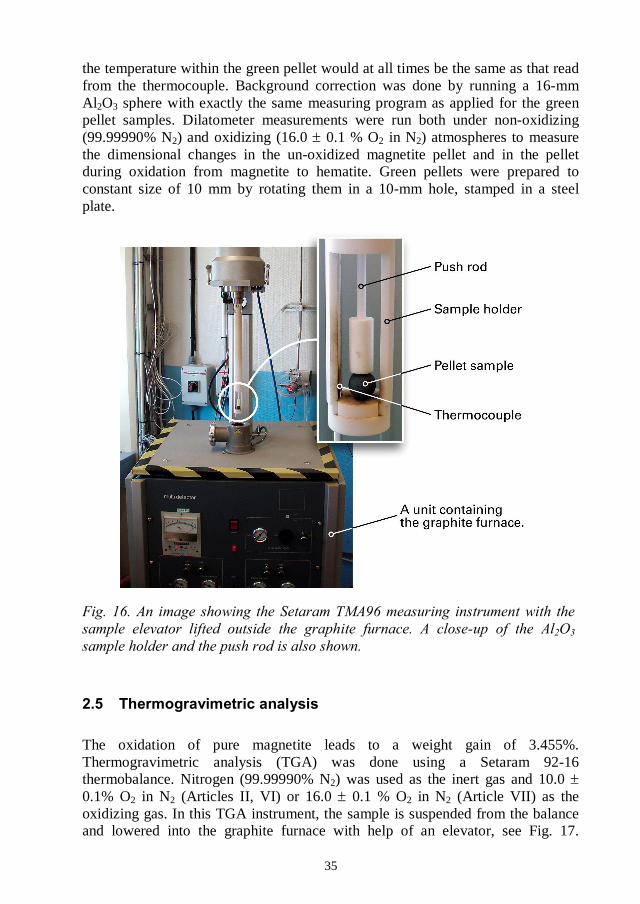
A Setaram TMA96 instrument was used in the dilatometer measurements. In theTMA96 instrument, the sample is placed on a Al2O3 sample holder, which isdescended in the graphite furnace with the help of an elevator, see Fig. 16. AnAl2O3 push rod is used to detect variations in sample dimensions as a function ofthe furnace temperature or time. A weight of 5 g was applied to the push rod toget good contact with the sample. The sample temperature is measured with athermocouple fastened to the Al2O3 sample holder, about 3 mm from the sample.A heating rate of 5oC/min was used. A slow heating rate was chosen to ensure that
35
the temperature within the green pellet would at all times be the same as that readfrom the thermocouple. Background correction was done by running a 16-mmAl2O3 sphere with exactly the same measuring program as applied for the greenpellet samples. Dilatometer measurements were run both under non-oxidizing(99.99990% N2) and oxidizing (16.0 0.1 % O2 in N2) atmospheres to measurethe dimensional changes in the un-oxidized magnetite pellet and in the pelletduring oxidation from magnetite to hematite. Green pellets were prepared toconstant size of 10 mm by rotating them in a 10-mm hole, stamped in a steelplate.
The oxidation of pure magnetite leads to a weight gain of 3.455%.Thermogravimetric analysis (TGA) was done using a Setaram 92-16thermobalance. Nitrogen (99.99990% N2) was used as the inert gas and 10.00.1% O2 in N2 (Articles II, VI) or 16.0 0.1 % O2 in N2 (Article VII) as theoxidizing gas. In this TGA instrument, the sample is suspended from the balanceand lowered into the graphite furnace with help of an elevator, see Fig. 17.

36
Powder samples were measured by using open, shallow platinum crucibles with avolume of 130 l (Articles II and VI). The sample size was 105 5 mg. Powdersamples were measured non-isothermally, using a heating rate of 5oC/min. Greenpellet samples were measured using a platinum wire-basket (Article VII). Thepellets were prepared to constant size of 10 mm by rotating them in a 10-mmhole.
The measurement of green pellet samples was started by pre-heating the pellet to800oC under nitrogen atmosphere for 60 minutes and then slowly cooling back toroom temperature, before starting the oxidation run. If no heat pre-treatment isdone before registering the oxidation weight gain, any loss of weight, likecalcining and especially the dehydration of the bentonite binder, would take placeduring the oxidation period and diminish the measured weight gain. At 800oC ininert gas, only normal thermal expansion takes place. The pre-heated and cooledgreen pellet was then weighed and returned to the suspension device. The greenpellet weight decreased by 0.22% during pre-heating. The oxidation experimentwas started by heating the furnace to the desired temperature while flushing with
37
the oxidizing gas. At this stage, the sample elevator was in the upper position withthe sample hanging outside the furnace. The sample inlet of the furnace wasclosed with a plate. The oxidation measurement was started by lowering thesample in the hot furnace. Using this method, the oxygen content in the oxidizinggas is constant. The first part of oxidation takes place non-isothermally as thesample temperature rises from room temperature to the furnace temperature. Thisis also the oxidation pattern for pellets in the full-scale pelletizing process.
Background correction was done by running two annealed Al2O3 spheres of aboutsimilar total weight as the green pellet. The background run showed about 1 mgincrease in sample weight, as a step-change directly after lowering the sample inthe furnace. This was subtracted from the oxidation run. This kind of backgroundcorrection does not take into account the apparent weight loss at the Curie point[Article II]. Also, the extent of the apparent weight loss can vary, depending onthe degree of oxidation in the pellet when the Curie point is reached. Therefore,the total oxidation weight gains obtained for pellets in these experiments areslightly too low. These errors are marginal and do not change the interpretation ofthe oxidation data.

38
39
3.1.1 Porosity in green pellets (I)
Porosity in green pellets has been traditionally measured by measuring the pelletsvolume when descended in mercury. At LKAB, the use of mercury was stoppedin 1998 and the porosity measurements were shifted over to the GeoPyc 1360instrument (Micromeritics Inc., USA). The reproducibility in these measurementswas approximately 0.7%-units in porosity and step-wise changes in the resultswere frequently observed. Because the total range of variation in green pelletporosity is normally only about 3%-units, from 30 to 33%, development work wasstarted to improve the repeatability of this measuring method.
Porosity is calculated by subtracting the volume of particles from the envelopevolume of pellets according to Eq. (5).
= (Ve m / p) / Ve (5)
where = fractional porosity, Ve = envelope volume of pellets, m = sample massand p = absolute density of particles.
Particle density was measured using the AccuPyc 1330 instrument. It is a simpleand well-documented measuring method [52]. The reproducibility isthe nominal sample chamber volume, which gives an error of 3 indensity for magnetite concentrate powders. This error in the density determinationleads to an error of et porosity, which is negligible. However,the particle densities tended initially to be too high and instable. This wasexplained by the fact that the bentonite binder is very hygroscopic and makes thegreen pellet samples susceptible to re-absorption of moisture after drying. In thepresence of rest-humidity, the error in the density measurement can appearalready in the second decimal and cause an appreciable error in the calculation ofporosity. The applied AccuPyc measuring procedure for green pellets is describedin detail in Article I.
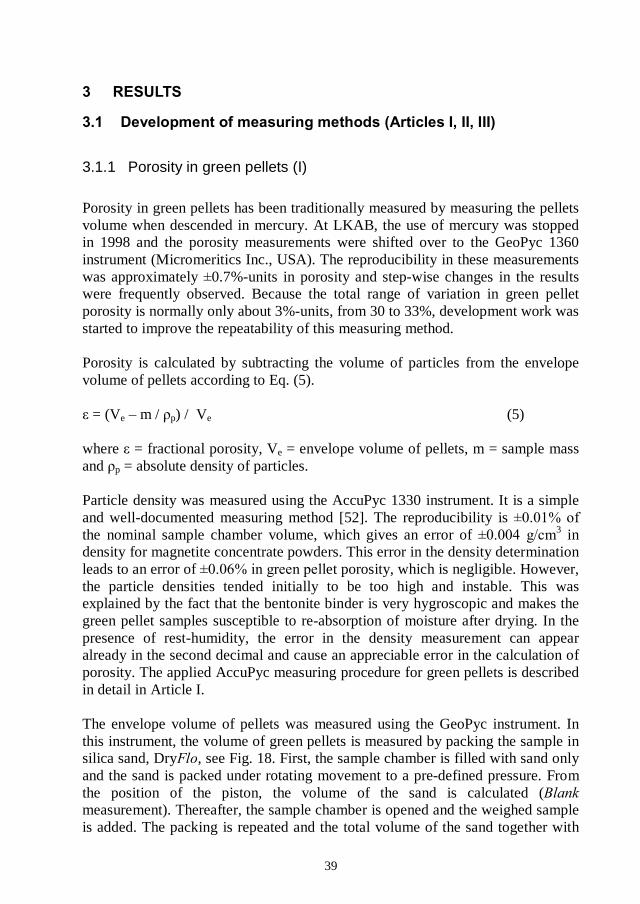
The envelope volume of pellets was measured using the GeoPyc instrument. Inthis instrument, the volume of green pellets is measured by packing the sample insilica sand, Dry , see Fig. 18. First, the sample chamber is filled with sand onlyand the sand is packed under rotating movement to a pre-defined pressure. Fromthe position of the piston, the volume of the sand is calculated (measurement). Thereafter, the sample chamber is opened and the weighed sampleis added. The packing is repeated and the total volume of the sand together with
40
the sample is obtained ( measurement). From the difference in volumebetween the and measurements, the sample envelope volume iscalculated. Detailed information about the choice of running conditions is given inArticle I.
During the GeoPyc measurement, the sample chamber is rotated to promote thepacking of the sand. This mechanical movement was found to cause abrasion ofthe green pellets. The green pellet envelope volume decreased and the measuredporosity became too low. Weak green pellets eroded more than stronger ones.Therefore, green pellets were sprayed with a fast drying lacquer to strengthenthem before GeoPyc measurement. After spraying, the samples were allowed todry over night. Measurements confirmed that the lacquer-treated green pelletsshowed systematically higher porosity values compared to un-treated samples.Reproducibility for lacquered in-house reference samples was -units inporosity (2 ). Details on the reproducibility measurements are shown in Article I.
The GeoPyc measurement was calibrated against a mercury pycnometer, seeresults in Fig. 19. In the mercury pycnometer, surface irregularities down to 9pore openings were filled with mercury. The calibration error was -units.The sample with 0.2% bentonite in Fig. 19 was excluded from the results, becausethese green pellets were very weak and tended to break in the mercurypycnometer. The level difference between the GeoPyc and mercury measurementswas 0.9 %-units in porosity, the porosity being larger in the mercurymeasurements.
In the GeoPyc instrument, a so-called conversion factor (CF) is used. This factoris primarily used to calculate the sample volume from the position of the piston,but can also be used to adjust the results level to a reference method. TheoreticalCF for the sample cylinder (D = 50.8 mm) is 2.037. Calibrating the GeoPycmeasurements to the same level with the mercury porosimeter changed the CFvalue to 2.064. This CF value was then used in all porosity measurements.

41
R2 = 0.94
29
30
31
32
33
29 30 31 32 33
Porosity by mercury pycnometer, %
Por
osity
byG
eoP
yc,%
x = yExcl.
(0.2% bent.)
Due to the improvements described above, good correlation between porosity andgreen pellet moisture content was obtained (Articles III and IV). Porosity alsoplays a vital role for understanding the green pellets behaviour when surface-active agents are present in the pellet feed (Article V). Understanding theoxidation and sintering behaviour of iron ore green pellets presumes that porosityin green pellets is known [Article VII]. These studies would not have beenpossible without a reliable porosity measurement.
3.1.2 Oxidation of magnetite concentrates during storage and drying (II)
For the pelletizing process, the oxidation of magnetite concentrates at hightemperatures, above 900oC, is naturally of main interest. However, when theoxidation studies were started, some discrepancy was found in the non-isothermalTGA curves. Background correction by the sample itself, run under nitrogenatmosphere, was applied because the KPC samples contain small amounts ofcarbonates. After the background correction, both the KPC and MPC samplesshowed higher oxidation mass gain values than expected from the chemicallyanalyzed Fe2+ values. In TGA curves run under nitrogen atmosphere, two broadweight loss bands were seen between 200oC and the Curie point. Further studiesshowed that the overestimation of the oxidation mass gain values was explainedpartly by the behaviour of the magnetite concentrate samples around the Curiepoint, and partly by oxidation of the samples that had taken place during storageand drying. These observations led to results published in Article II. Below, firstthe results showing oxidation of magnetite concentrate pellet feeds during storageand drying are briefly reviewed, and then the consequences for the total oxidationweight gain calculated from a TGA run are explained.

42
LKAB magnetite pellet concentrates are wet ground and therefore sampled asslurries and dried at 105oC. Because of the large amount of water, drying takes afew days. To study possible oxidation during drying, typical KPC and MPCsamples were freeze-dried and measured in TGA by running them isothermally at75oC, 105oC and 130oC for 48 hours under oxidizing conditions. Thecorresponding weight gain curves are shown in Figures 20 and 21. At 75oC, nooxidation could be seen. At 105oC, the MPC sample showed distinct oxidation(0.19% Fe2+), especially during the first 24 hours. When the temperature wasraised to 130oC, the KPC sample also oxidized in measurable amounts (0.17%Fe2+). The results show that drying of magnetite concentrates of typical pelletizingfineness at 105oC is questionable, although 105oC is recommended by ISO 7764[53] and ISO 3087 [54] and given as the maximum allowable drying temperaturein ISO 3082 [55]. The importance of the drying time should also be recognized.The samples should be removed from the drying furnace as soon as they are dryand not left there, for example, over weekends.
0.00
0.10
0.20
0.30
0.40
0 10 20 30 40 50
Time, hours
Oxi
datio
n,%
Fe
75 105 130
130
105
750.00
0.10
0.20
0.30
0.40
0 10 20 30 40 50
Time, hours
Oxi
da
tion
,%F
e
75 105 130
130
105
75
Oxidation during storage at room temperature was detected as well. The Fe2+
content in a normal LKAB pellet feed decreased by 0.3%-units during four yearsof storage at room temperature. Oxidation during storage was completelyhindered when the samples were stored in a freezer at -50oC. Therefore, forprolonged storage of magnetite concentrate samples (like reference materials),storage in a freezer is recommended. Oxidation during storage was also followedby regularly running TGA on the MPC and KPC samples stored at roomtemperature. The results showed that the oxidation product formed during storageat room temperature is -hematite, which starts to nucleate to -hematite at around270oC [Article II].

43
The two broad weight loss bands found in DTG curves collected under nitrogenatmosphere are shown in Fig. 22. The samples are MPC magnetite concentratestored either at room temperature or in a freezer for four years. MPC samples donot contain measurable amounts of carbonates. The first weight loss bandappeared between 200oC and 350oC and was only found in the sample stored atroom temperature. This weight loss corresponds to 0.3% Fe2+ (0.043 dm%) and isexplained by the dissociation of -hematite (formed during storage at roomtemperature), back to magnetite [56]. The second weight loss band between 400and 600oC is connected to the Curie point. A sharp overlying peak with a suddenweight loss appeared at the exact Curie temperature (563oC). Under the runningconditions used in this study, the apparent weight loss caused by the Curie point(in N2) corresponded to 0.24% Fe2+ (0.035 dm%). The weight loss at the Curiepoint during an oxidation run is smaller, because part of the sample has alreadyoxidized to hematite when the Curie point is reached.
Stored at -50 C
Stored at room temperature
Stored at room temperature
Stored at -50 C
TG
DTG
Curie point Temperature/ C
TG / % DTG / %/min
Background correction by the sample itself, is based on the assumption that anypossible weight loss from the sample takes place in a similar manner both undernon-oxidizing and oxidizing atmospheres. However, the above describeddissociation weight loss only appears under non-oxidizing atmosphere and theapparent weight loss around the Curie point is larger under non-oxidizingatmosphere. This makes the background correction too large and the net weightgain during oxidation is over estimated. The weight loss due to dissociation of -hematite back to magnetite (under non-oxidizing atmosphere) can be utilized toestimate the amount of -hematite formed during storage or drying and that way,
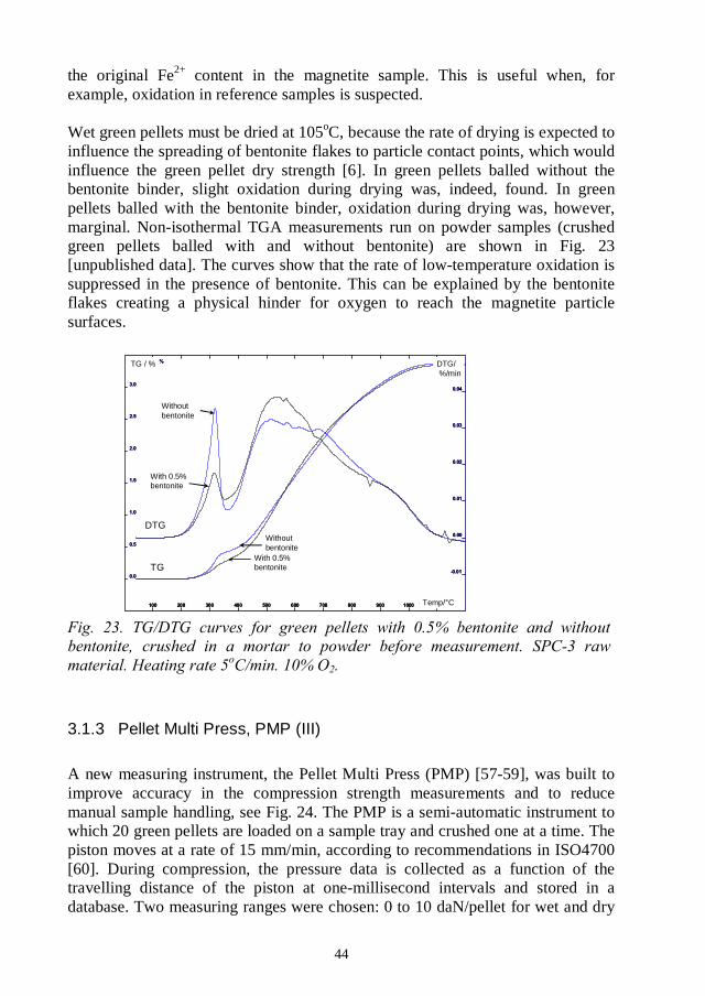
44
the original Fe2+ content in the magnetite sample. This is useful when, forexample, oxidation in reference samples is suspected.
Wet green pellets must be dried at 105oC, because the rate of drying is expected toinfluence the spreading of bentonite flakes to particle contact points, which wouldinfluence the green pellet dry strength [6]. In green pellets balled without thebentonite binder, slight oxidation during drying was, indeed, found. In greenpellets balled with the bentonite binder, oxidation during drying was, however,marginal. Non-isothermal TGA measurements run on powder samples (crushedgreen pellets balled with and without bentonite) are shown in Fig. 23[unpublished data]. The curves show that the rate of low-temperature oxidation issuppressed in the presence of bentonite. This can be explained by the bentoniteflakes creating a physical hinder for oxygen to reach the magnetite particlesurfaces.
Temp/ C
DTG/%/min
TG / %
With 0.5%bentonite
With 0.5%bentonite
Withoutbentonite
Withoutbentonite
TG
DTG
3.1.3 Pellet Multi Press, PMP (III)
A new measuring instrument, the Pellet Multi Press (PMP) [57-59], was built toimprove accuracy in the compression strength measurements and to reducemanual sample handling, see Fig. 24. The PMP is a semi-automatic instrument towhich 20 green pellets are loaded on a sample tray and crushed one at a time. Thepiston moves at a rate of 15 mm/min, according to recommendations in ISO4700[60]. During compression, the pressure data is collected as a function of thetravelling distance of the piston at one-millisecond intervals and stored in adatabase. Two measuring ranges were chosen: 0 to 10 daN/pellet for wet and dry

45
green pellets and 0 to 100 daN/pellet for exceptionally strong dry green pellets orfor partly oxidized magnetite green pellets. After crushing, the pressure curvescan be visually examined and are mathematically evaluated. A set of evaluationrules was developed, as explained later. The average values, standard deviations,minimum and maximum values are calculated. The daN units are used inaccordance with ISO4700 [60] to adapt the numerical values to the same level asin earlier iron ore pelletizing literature; 1 daN = 10 N = 1.02 kg.
3.1.4 Green pellet compression strength and sorting by breakage pattern(III)
The point of breakage in green pellets is defined as the maximum load after whichthe pressure falls by at least 10%. The breakage curves differ considerably,depending on the nature of bindings. To be able to describe the shape of thecrushing curves numerically in a table of figures, the curves were classifiedaccording to their breakage pattern into three groups, see Fig. 25. In group A, thebreakage pattern is very distinct. After the breakage point, the pressure drops bymore than 80% of the maximum value. This kind of breakage pattern is onlyfound in dry green pellets. If the pressure drop is between 50 and 80%, the greenpellet is classed to belong to group B. This pattern is typical for weaker bindings,when a moredrop is between 10 and 50%, the green pellet is classed as group C. B- and C-typebreakage patterns are found in both dry and wet green pellets.
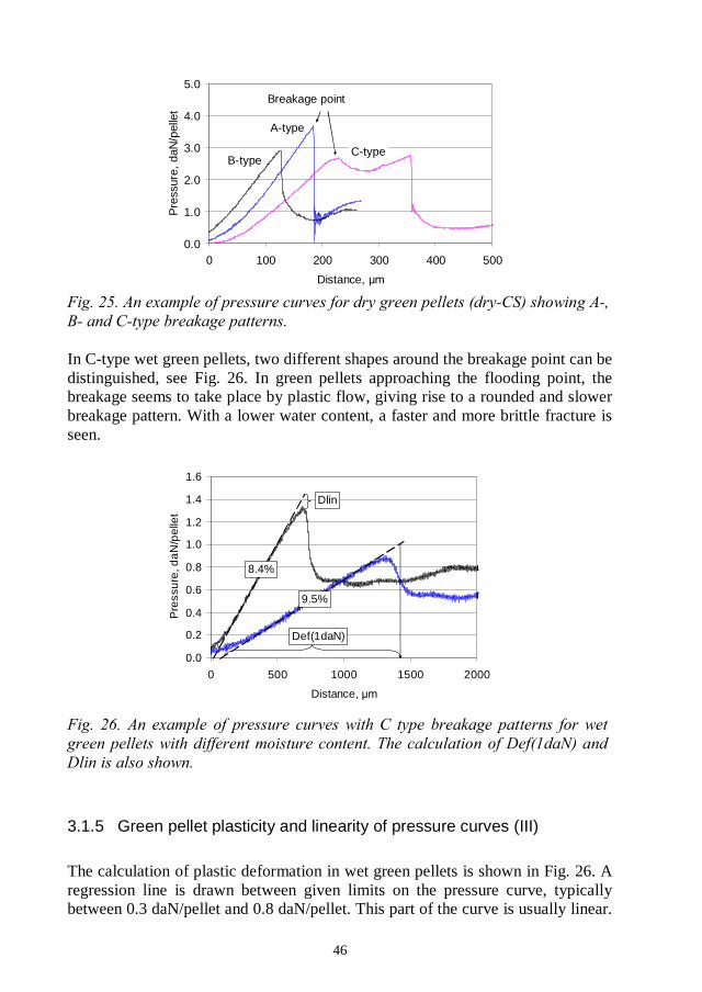
46
0.0
1.0
2.0
3.0
4.0
5.0
0 100 200 300 400 500
Distance,
Pre
ssur
e,da
N/p
elle
t
A-type
B-type
Breakage point
C-type
In C-type wet green pellets, two different shapes around the breakage point can bedistinguished, see Fig. 26. In green pellets approaching the flooding point, thebreakage seems to take place by plastic flow, giving rise to a rounded and slowerbreakage pattern. With a lower water content, a faster and more brittle fracture isseen.
0.0
0.2
0.4
0.6
0.8
1.0
1.2
1.4
1.6
0 500 1000 1500 2000
Distance,
Pre
ssur
e,d
aN/p
elle
t
Dlin
Def(1daN)
8.4%
9.5%
3.1.5 Green pellet plasticity and linearity of pressure curves (III)
The calculation of plastic deformation in wet green pellets is shown in Fig. 26. Aregression line is drawn between given limits on the pressure curve, typicallybetween 0.3 daN/pellet and 0.8 daN/pellet. This part of the curve is usually linear.

47
The amount of deformation when the green pellet is gradually loaded with a forceof 1 daN, Def(1daN), is read as a distance between the piston positions at theregression line intercept with the x-axis and at a pressure of 1 daN/pellet. If thegreen pellet is weaker than 1 daN/pellet, the regression line is extended over thebreakage point to 1 daN/pellet. This way, the deformation values are independentof the green pellet strength. 1 daN/pellet was chosen as a reference point for thecalculation of plastic deformation because wet iron ore green pellets normallyneed to withstand this load. Def(1daN) is expressed in micrometer units.
The calculation of Def(1daN) is done automatically. However, the pressure curvesare sometimes slightly S-shaped, which can lead to an incorrectly drawnregression line. Therefore, a measure named (Dlin) wasdefined. Dlin is the difference in compression pressure read from the regressionline compared to the actually measured value at the breakage point, see Fig. 26.Dlin is expressed in units daN/pellet. If Dlin is zero, the pressure curve iscompletely linear up to the breakage point. If Dlin is positive, the pressure curvestarts deviating before the breakage point is achieved. If Dlin is negative, theregression line is incorrectly drawn and not relevant for the calculation of plasticdeformation. In most cases, this can be corrected by choosing new limits for thecalculation of the regression line. This is easily done with the evaluation software.
3.1.6 High-speed camera images (III)
A high-speed camera (maximum 200 images per second with 640x480 resolution)was connected to the PMP instrument for registration of the green pellet breakagewhen desired, see Fig. 27. The film sequences can be synchronized with thepressure curves. Some images of typical breakage patterns are shown in Chapter3.6.
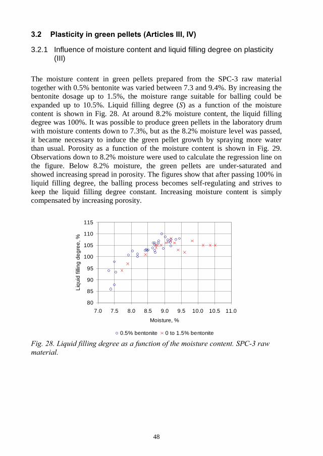
48
3.2.1 Influence of moisture content and liquid filling degree on plasticity(III)
The moisture content in green pellets prepared from the SPC-3 raw materialtogether with 0.5% bentonite was varied between 7.3 and 9.4%. By increasing thebentonite dosage up to 1.5%, the moisture range suitable for balling could beexpanded up to 10.5%. Liquid filling degree ( ) as a function of the moisturecontent is shown in Fig. 28. At around 8.2% moisture content, the liquid fillingdegree was 100%. It was possible to produce green pellets in the laboratory drumwith moisture contents down to 7.3%, but as the 8.2% moisture level was passed,it became necessary to induce the green pellet growth by spraying more waterthan usual. Porosity as a function of the moisture content is shown in Fig. 29.Observations down to 8.2% moisture were used to calculate the regression line onthe figure. Below 8.2% moisture, the green pellets are under-saturated andshowed increasing spread in porosity. The figures show that after passing 100% inliquid filling degree, the balling process becomes self-regulating and strives tokeep the liquid filling degree constant. Increasing moisture content is simplycompensated by increasing porosity.
80
85
90
95
100
105
110
115
7.0 7.5 8.0 8.5 9.0 9.5 10.0 10.5 11.0
Moisture, %
Liq
uid
fillin
gde
gre
e,%
0.5% bentonite 0 to 1.5% bentonite
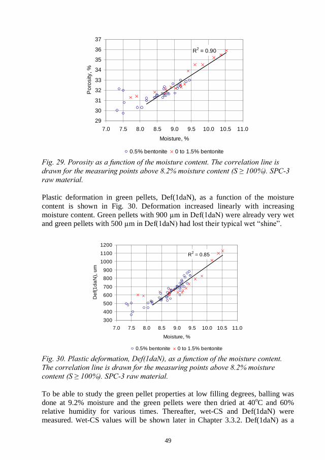
49
R2 = 0.90
29
30
31
32
33
34
35
36
37
7.0 7.5 8.0 8.5 9.0 9.5 10.0 10.5 11.0
Moisture, %
Po
rosi
ty,%
0.5% bentonite 0 to 1.5% bentonite
Plastic deformation in green pellets, Def(1daN), as a function of the moisturecontent is shown in Fig. 30. Deformation increased linearly with increasingmoisture content. Green pellets with 900 ere already very wetand green pellets with 500
R2 = 0.85
300
400
500
600
700
800
900
1000
1100
1200
7.0 7.5 8.0 8.5 9.0 9.5 10.0 10.5 11.0
Moisture, %
De
f(1
da
N),
um
0.5% bentonite 0 to 1.5% bentonite
To be able to study the green pellet properties at low filling degrees, balling wasdone at 9.2% moisture and the green pellets were then dried at 40oC and 60%relative humidity for various times. Thereafter, wet-CS and Def(1daN) weremeasured. Wet-CS values will be shown later in Chapter 3.3.2. Def(1daN) as a

50
function of the liquid filling degree is shown in Fig. 31. A large, linear increase inplastic deformation was seen as soon as the liquid filling degree exceeded 100%.At < 100%, deformation became constant. At < 70%, the deformation valuesfurther decreased, probably because dry bentonite bindings started to form. At =100% the particles are packed to minimum porosity (maximum packing density).The pores are filled with water, but there is not enough water to create liquid glideplanes between particles. At > 100% the increasing moisture contentthe particles by drawing them further apart from each other. Liquid glide planesbetween particles are formed and plastic deformation of the agglomerates begins.
200
300
400
500
600
700
800
900
1000
0 10 20 30 40 50 60 70 80 90 100 110
Liquid filling degree, %
De
f(1da
N),
After drying Balled directly at given S
The sorting of wet green pellets by the breakage pattern showed a change in thebreakage mechanism at = 100% (8.2% moisture), see Fig. 32. In wet greenpellets, only breakage patterns of type C and B are found. At 9.4% moisture,practically all green pellets showed the C-type breakage pattern where breakagetakes place by plastic flow. As the moisture content decreased, the proportion ofB-type breakage pattern gradually increased and the C-type breakagecorrespondingly decreased. Finally, at around 8.2% moisture, all green pelletsshowed the more brittle B-type breakage.

51
0
10
20
30
40
50
60
70
80
90
100
7.0 7.5 8.0 8.5 9.0 9.5
Moisture, %
B-t
ype
bre
aka
ge
,%
3.2.2 Influence of raw material fineness on plasticity (IV)
MPC and SPC samples with varying fineness (see Table 1) were balled with 0.5%bentonite binder at different moisture contents. All the MPC and SPC sampleswere collected on the same porosity-moisture correlation line as shown earlier inFig. 29. This ascertains that the porosity-moisture correlation is independent ofraw material fineness as long as the amount of air inclusions in green pellets issmall and constant and the same measuring method for the determination ofporosity is used. However, different materials show very different plasticity at agiven moisture content.
Plasticity, Def(1daN), as a function of the moisture content in the MPC and SPCsamples is shown in Fig. 33 and 34, respectively. The figures show that as the rawmaterial became finer, an increasing amount of water was needed to createplasticity in green pellets. The MPC and SPC samples clearly separated to theirown groups. At 8.2% moisture content, the MPC samples showed plasticityvalues between 600 and 800while the SPC samples at 8.2% moisture, all showed very low plasticity (500indicating that the green pellets were dry and fragile. Two of the samples showeddeviating behaviour, namely MPC-2 and SPC-4. The reasons for this deviatingbehaviour could not be verified. It highlights, however, that particle sizedistribution is only one parameter controlling the moisture content needed inballing.
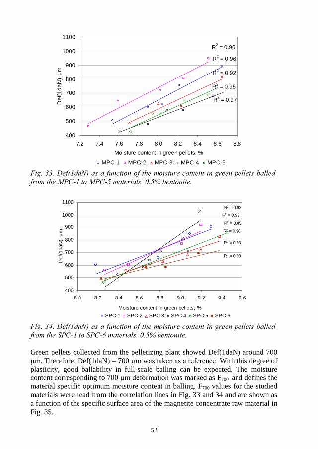
52
R2 = 0.96
R2 = 0.96
R2 = 0.92
R2 = 0.97
R2 = 0.95
400
500
600
700
800
900
1000
1100
7.2 7.4 7.6 7.8 8.0 8.2 8.4 8.6 8.8
Moisture content in green pellets, %
Def
(1d
aN),
MPC-1 MPC-2 MPC-3 MPC-4 MPC-5
R2 = 0.85
R2 = 0.98
R2 = 0.93
R2 = 0.92
R2 = 0.92
R2 = 0.93
400
500
600
700
800
900
1000
1100
8.0 8.2 8.4 8.6 8.8 9.0 9.2 9.4 9.6
Moisture content in green pellets, %
Def
(1da
N),
SPC-1 SPC-2 SPC-3 SPC-4 SPC-5 SPC-6
Green pellets collected from the pelletizing plant showed Def(1daN) around 700. Therefore, Def(1daN) = 700 . With this degree of
plasticity, good ballability in full-scale balling can be expected. The moisturecontent corresponding to 700 was marked as F700 and defines thematerial specific optimum moisture content in balling. F700 values for the studiedmaterials were read from the correlation lines in Fig. 33 and 34 and are shown asa function of the specific surface area of the magnetite concentrate raw material inFig. 35.

53
R2 = 0.75
R2 = 0.82
7.6
8.0
8.4
8.8
9.2
9.6
9000 10000 11000 12000 13000
Specific surface area, cm
F70
0,%
MPC samples SPC samples
The separation between the MPC and SPC samples was distinct. With 10,000cm2/cm3 specific surface area, F700 varied between 8.1 and 8.9%, depending onthe origin of the sample. If the F700 values are drawn against the %-45fraction, the two sample groups are brought closer to each other, although theystill separate, see Fig. 36.
R2 = 0.70
R2 = 0.80
7.6
8.0
8.4
8.8
9.2
9.6
64 66 68 70 72 74 76 78 80 82
Screening, %-45
F70
0,%
MPC samples SPC samples
This means that neither the fine tail, nor the large particles can predict theamount of water needed in balling. Instead, when the F700 values are drawnagainst the between the %-45 and %-13 , marked here as D45-13
(describes the slope of the particle size distribution), both sample groups arecollected on the same correlation line, see Fig. 37. The prediction error for F700
was 0.2% in F700.
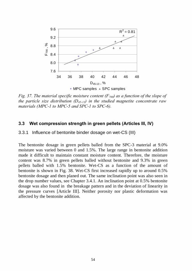
54
R2 = 0.81
7.6
8.0
8.4
8.8
9.2
9.6
34 36 38 40 42 44 46 48
D45-13 , %
F70
0,%
MPC samples SPC samples
3.3.1 Influence of bentonite binder dosage on wet-CS (III)
The bentonite dosage in green pellets balled from the SPC-3 material at 9.0%moisture was varied between 0 and 1.5%. The large range in bentonite additionmade it difficult to maintain constant moisture content. Therefore, the moisturecontent was 8.7% in green pellets balled without bentonite and 9.3% in greenpellets balled with 1.5% bentonite. Wet-CS as a function of the amount ofbentonite is shown in Fig. 38. Wet-CS first increased rapidly up to around 0.5%bentonite dosage and then planed out. The same inclination point was also seen inthe drop number values, see Chapter 3.4.1. An inclination point at 0.5% bentonitedosage was also found in the breakage pattern and in the deviation of linearity inthe pressure curves [Article III]. Neither porosity nor plastic deformation wasaffected by the bentonite addition.
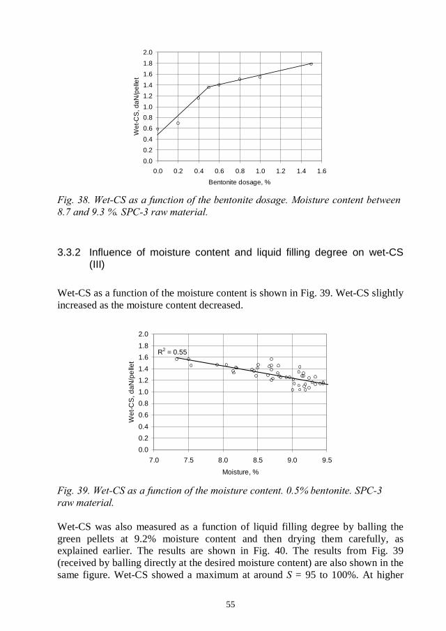
55
0.0
0.2
0.4
0.6
0.8
1.0
1.2
1.4
1.6
1.8
2.0
0.0 0.2 0.4 0.6 0.8 1.0 1.2 1.4 1.6
Bentonite dosage, %
Wet
-CS
,da
N/p
elle
t
3.3.2 Influence of moisture content and liquid filling degree on wet-CS(III)
Wet-CS as a function of the moisture content is shown in Fig. 39. Wet-CS slightlyincreased as the moisture content decreased.
R2 = 0.55
0.0
0.2
0.4
0.6
0.8
1.0
1.2
1.4
1.6
1.8
2.0
7.0 7.5 8.0 8.5 9.0 9.5
Moisture, %
Wet
-CS
,daN
/pe
llet
Wet-CS was also measured as a function of liquid filling degree by balling thegreen pellets at 9.2% moisture content and then drying them carefully, asexplained earlier. The results are shown in Fig. 40. The results from Fig. 39(received by balling directly at the desired moisture content) are also shown in thesame figure. Wet-CS showed a maximum at around = 95 to 100%. At higher

56
saturations, wet-CS decreased slightly as the flooding point at around = 110%approached. The green pellets were weakest when dropped to about 70%. Atthis point, some of the capillaries have been drained of water, but dry bentonitebindings have not yet started to form. As the dry bentonite bindings started toform, the compression strength increased rapidly.
Liquid saturation, %
W et-CS, daN/pellet
0 10 20 30 40 50 60 70 80 90 100 1100,5
1
4
3
2
5
Balled directly at given SAfter drying
3.3.3 Influence of raw material fineness on wet-CS (IV)
The MPC and SPC samples of varying fineness were balled with 0.5% bentonitebinder, partly at the material specific moisture content (F700, constant plasticity),partly at a constant moisture content (8.2%). In green pellets balled at F700, nodependency on raw material fineness was found, see Fig. 41. No differencebetween the MPC and SPC samples was found either, although the MPC sampleshave a broader particle size distribution compared to the SPC samples.
When green pellets balled at constant moisture content and with 0.5% bentoniteare compared (see Fig. 42), the two coarsest MPC samples (MPC-1 and MPC-2)would be classified as too coarse, because of the weak green pellets. Wet-CSvalues for green pellets balled without bentonite are shown in Fig. 43. Wet-CSincreased when the raw material became finer, especially after exceeding thespecific surface area of about 11,000 cm2/cm3.

57
0.40
0.60
0.80
1.00
1.20
1.40
9000 10000 11000 12000 13000
Specific surface area, cm
Wet
-CS
,daN
/pel
let
MPC samples SPC samples
.
0.40
0.60
0.80
1.00
1.20
1.40
9000 10000 11000 12000 13000
Specific surface area, cm
We
t-CS
,da
N/p
elle
t
MPC samples SPC samples
MPC-1
MPC-2
R2 = 0.93
0.40
0.60
0.80
1.00
1.20
1.40
9000 10000 11000 12000 13000
Specific surface area, cm
Wet
-CS
,daN
/pel
let
MPC samples SPC samples
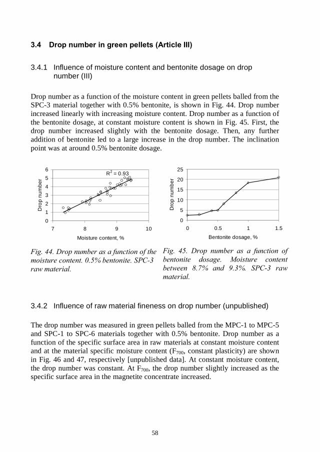
58
3.4.1 Influence of moisture content and bentonite dosage on dropnumber (III)
Drop number as a function of the moisture content in green pellets balled from theSPC-3 material together with 0.5% bentonite, is shown in Fig. 44. Drop numberincreased linearly with increasing moisture content. Drop number as a function ofthe bentonite dosage, at constant moisture content is shown in Fig. 45. First, thedrop number increased slightly with the bentonite dosage. Then, any furtheraddition of bentonite led to a large increase in the drop number. The inclinationpoint was at around 0.5% bentonite dosage.
R2 = 0.93
0
1
2
3
4
5
6
7 8 9 10
Moisture content, %
Dro
pn
um
be
r
0
5
10
15
20
25
0 0.5 1 1.5
Bentonite dosage, %
Dro
pn
um
be
r
3.4.2 Influence of raw material fineness on drop number (unpublished)
The drop number was measured in green pellets balled from the MPC-1 to MPC-5and SPC-1 to SPC-6 materials together with 0.5% bentonite. Drop number as afunction of the specific surface area in raw materials at constant moisture contentand at the material specific moisture content (F700, constant plasticity) are shownin Fig. 46 and 47, respectively [unpublished data]. At constant moisture content,the drop number was constant. At F700, the drop number slightly increased as thespecific surface area in the magnetite concentrate increased.
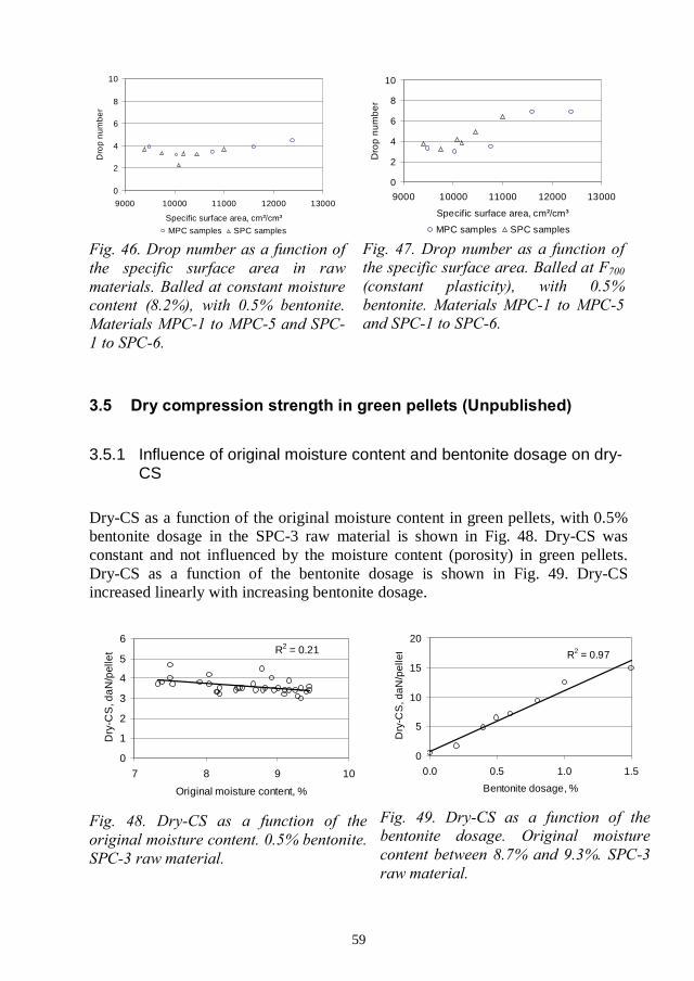
59
0
2
4
6
8
10
9000 10000 11000 12000 13000
Specific surface area, cm
Dro
pn
umb
er
MPC samples SPC samples
0
2
4
6
8
10
9000 10000 11000 12000 13000
Specific surface area, cm
Dro
pn
um
be
r
MPC samples SPC samples
3.5.1 Influence of original moisture content and bentonite dosage on dry-CS
Dry-CS as a function of the original moisture content in green pellets, with 0.5%bentonite dosage in the SPC-3 raw material is shown in Fig. 48. Dry-CS wasconstant and not influenced by the moisture content (porosity) in green pellets.Dry-CS as a function of the bentonite dosage is shown in Fig. 49. Dry-CSincreased linearly with increasing bentonite dosage.
R2 = 0.21
0
1
2
3
4
5
6
7 8 9 10
Original moisture content, %
Dry
-CS
,da
N/p
elle
t R2 = 0.97
0
5
10
15
20
0.0 0.5 1.0 1.5
Bentonite dosage, %
Dry
-CS
,daN
/pel
let
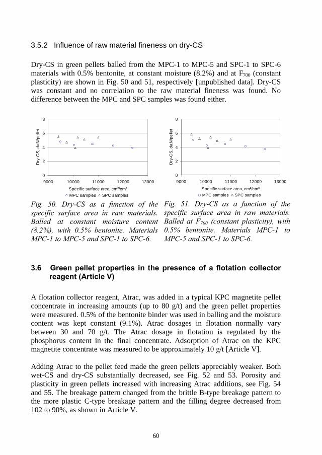
60
3.5.2 Influence of raw material fineness on dry-CS
Dry-CS in green pellets balled from the MPC-1 to MPC-5 and SPC-1 to SPC-6materials with 0.5% bentonite, at constant moisture (8.2%) and at F700 (constantplasticity) are shown in Fig. 50 and 51, respectively [unpublished data]. Dry-CSwas constant and no correlation to the raw material fineness was found. Nodifference between the MPC and SPC samples was found either.
0
2
4
6
8
9000 10000 11000 12000 13000
Specific surface area, cm
Dry
-CS
,daN
/pel
let
MPC samples SPC samples
0
2
4
6
8
9000 10000 11000 12000 13000
Specific surface area, cm
Dry
-CS
,da
N/p
elle
t
MPC samples SPC samples
A flotation collector reagent, Atrac, was added in a typical KPC magnetite pelletconcentrate in increasing amounts (up to 80 g/t) and the green pellet propertieswere measured. 0.5% of the bentonite binder was used in balling and the moisturecontent was kept constant (9.1%). Atrac dosages in flotation normally varybetween 30 and 70 g/t. The Atrac dosage in flotation is regulated by thephosphorus content in the final concentrate. Adsorption of Atrac on the KPCmagnetite concentrate was measured to be approximately 10 g/t [Article V].
Adding Atrac to the pellet feed made the green pellets appreciably weaker. Bothwet-CS and dry-CS substantially decreased, see Fig. 52 and 53. Porosity andplasticity in green pellets increased with increasing Atrac additions, see Fig. 54and 55. The breakage pattern changed from the brittle B-type breakage pattern tothe more plastic C-type breakage pattern and the filling degree decreased from102 to 90%, as shown in Article V.
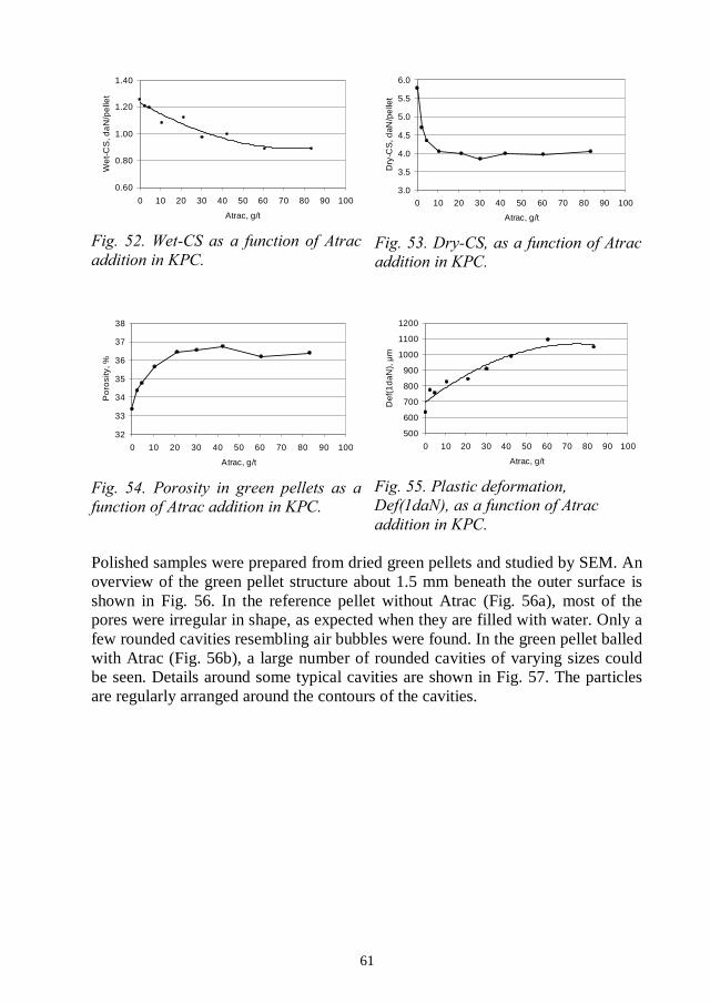
61
0.60
0.80
1.00
1.20
1.40
0 10 20 30 40 50 60 70 80 90 100
Atrac, g/t
We
t-C
S,d
aN
/pe
llet
3.0
3.5
4.0
4.5
5.0
5.5
6.0
0 10 20 30 40 50 60 70 80 90 100
Atrac, g/t
Dry
-CS
,daN
/pe
llet
32
33
34
35
36
37
38
0 10 20 30 40 50 60 70 80 90 100
Atrac, g/t
Po
rosi
ty,%
500
600
700
800
900
1000
1100
1200
0 10 20 30 40 50 60 70 80 90 100
Atrac, g/t
Def
(1d
aN),
Polished samples were prepared from dried green pellets and studied by SEM. Anoverview of the green pellet structure about 1.5 mm beneath the outer surface isshown in Fig. 56. In the reference pellet without Atrac (Fig. 56a), most of thepores were irregular in shape, as expected when they are filled with water. Only afew rounded cavities resembling air bubbles were found. In the green pellet balledwith Atrac (Fig. 56b), a large number of rounded cavities of varying sizes couldbe seen. Details around some typical cavities are shown in Fig. 57. The particlesare regularly arranged around the contours of the cavities.
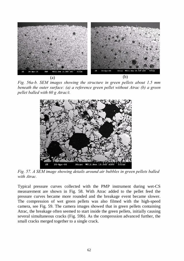
62
(a) (b)
Typical pressure curves collected with the PMP instrument during wet-CSmeasurement are shown in Fig. 58. With Atrac added to the pellet feed thepressure curves became more rounded and the breakage event became slower.The compression of wet green pellets was also filmed with the high-speedcamera, see Fig. 59. The camera images showed that in green pellets containingAtrac, the breakage often seemed to start inside the green pellets, initially causingseveral simultaneous cracks (Fig. 59b). As the compression advanced further, thesmall cracks merged together to a single crack.
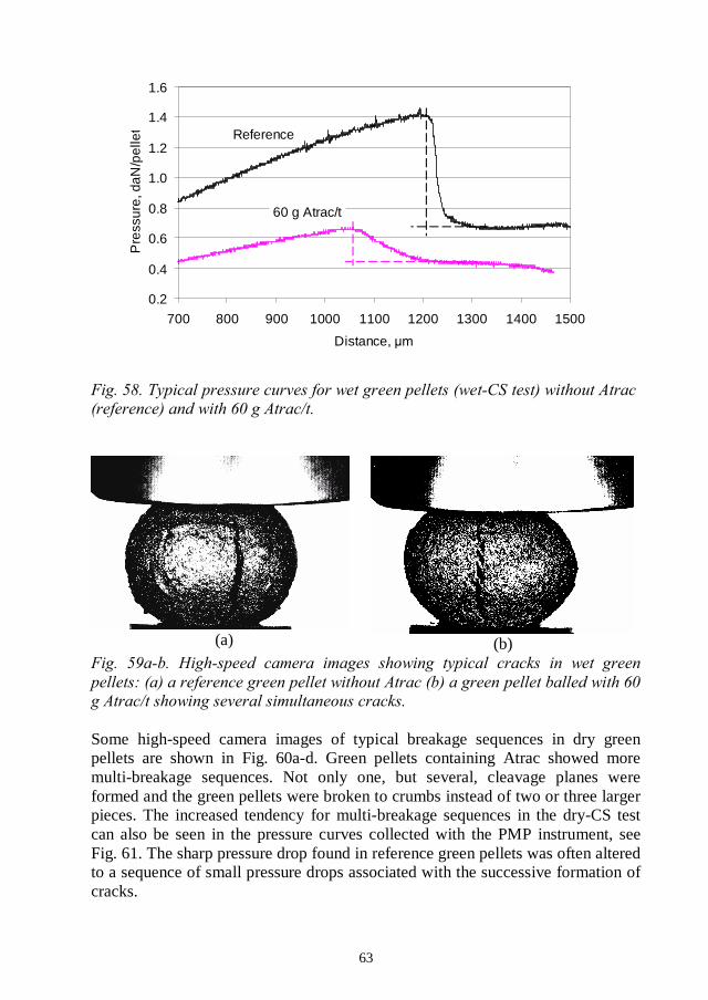
63
0.2
0.4
0.6
0.8
1.0
1.2
1.4
1.6
700 800 900 1000 1100 1200 1300 1400 1500
Distance,
Pre
ssur
e,da
N/p
elle
t Reference
60 g Atrac/t
(a) (b)
Some high-speed camera images of typical breakage sequences in dry greenpellets are shown in Fig. 60a-d. Green pellets containing Atrac showed moremulti-breakage sequences. Not only one, but several, cleavage planes wereformed and the green pellets were broken to crumbs instead of two or three largerpieces. The increased tendency for multi-breakage sequences in the dry-CS testcan also be seen in the pressure curves collected with the PMP instrument, seeFig. 61. The sharp pressure drop found in reference green pellets was often alteredto a sequence of small pressure drops associated with the successive formation ofcracks.
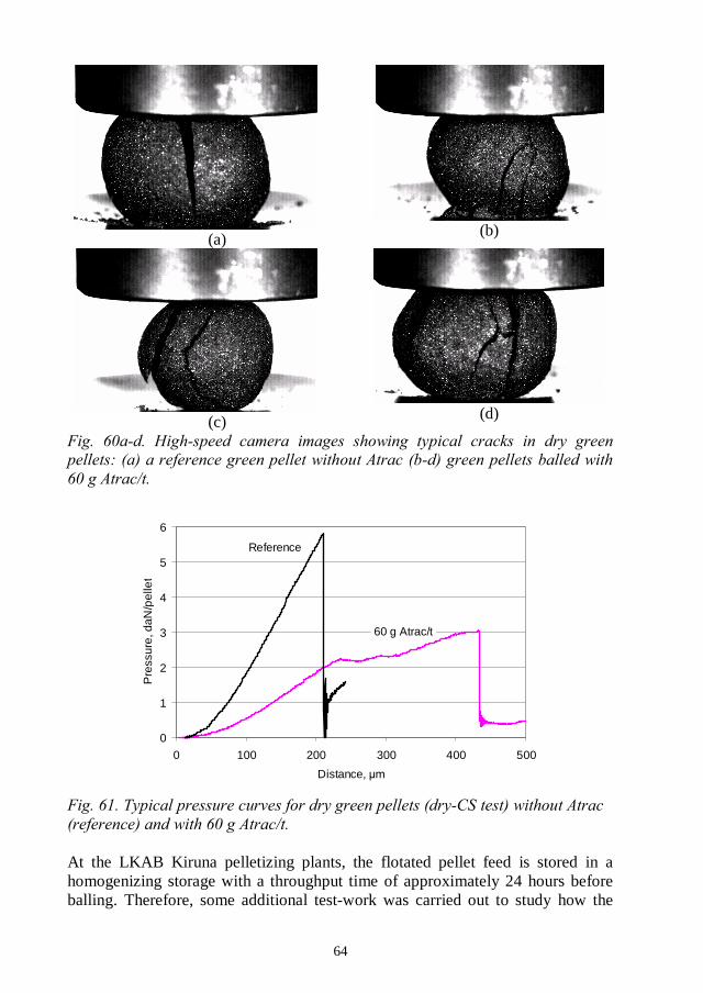
64
(a) (b)
(c) (d)
0
1
2
3
4
5
6
0 100 200 300 400 500
Distance,
Pre
ssur
e,da
N/p
elle
t
Reference
60 g Atrac/t
At the LKAB Kiruna pelletizing plants, the flotated pellet feed is stored in ahomogenizing storage with a throughput time of approximately 24 hours beforeballing. Therefore, some additional test-work was carried out to study how the

65
storage time would influence the behaviour of the flotated pellet feeds. For thispurpose, 60 g/t and 20 g/t Atrac was added to the magnetite concentrate and themixture was then allowed to stand at room temperature for different times beforeballing. Blank samples were prepared with exactly the same treatment, butwithout Atrac additions. The changes in wet-CS and porosity as a function of thestorage time, on the two different Atrac dosage levels, are shown in Fig. 62 and63 [unpublished data]. The results show a gradual improvement in green pelletquality as a function of the storage time. With 60 g Atrac/t added to the pelletfeed, about one third of the difference in wet-CS and porosity was restored within24 hours. With 20 g Atrac/t, a storage time of 24 hours seemed to be enough torestore the original green pellet quality.
0.80
1.00
1.20
1.40
1.60
0 1 2 3 4 5 6 7Storage time before balling, days
Wet
-CS
,daN
/pel
let
60 g Atrac/t 20 g Atrac/t Blank samples
32
33
34
35
36
37
38
0 1 2 3 4 5 6 7Storage time before balling, days
Por
osity
,%
60 g atrac/t 20 g atrac/t Blank samples
3.7.1 Interpretation of dilatation curves for green pellets (VII)
When a green pellet starts to oxidize, a shell of hematite is formed around thepellet while the core is still magnetite. Displacement curves (Disp) andcorresponding derivate curves (dDisp) were measured for green pellets under non-oxidizing and oxidizing atmospheres to separately describe thermal volumechanges in these two phases. The dilatation curve collected under nitrogenatmosphere is used to describe the behaviour of the magnetite core in pellets. Thedilatation curve collected under oxidizing atmosphere is used to describe thebehaviour of the oxidized hematite shell in pellets.
Dilatation curves for green pellets prepared from the MPC-5 raw material andmeasured under non-oxidizing and oxidizing atmospheres are shown in Fig. 64(Disp) and Fig. 65 (dDisp). Under non-oxidizing atmosphere, linear expansion upto 800oC was found. The breakpoint seen at 570oC is the Curie point. The
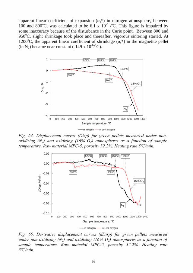
66
apparent linear coefficient of expansion ( e*) in nitrogen atmosphere, between100 and 800oC, was calculated to be 6.1 x 10⁻⁶ /oC. This figure is impaired bysome inaccuracy because of the disturbance in the Curie point. Between 800 and950oC, slight shrinkage took place and thereafter, vigorous sintering started. At1200oC, the apparent linear coefficient of shrinkage ( s*) in the magnetite pellet(in N2) became near constant (-149 x 10-6/oC).
-4
-3
-2
-1
0
1
0 100 200 300 400 500 600 700 800 900 1000 1100 1200 1300 1400
Sample temperature,
Dis
p,%
in nitrogen in 16% oxygen
N2
16% O2
330
570 800 950
1100
900
-0.10
-0.08
-0.06
-0.04
-0.02
0.00
0.02
0 100 200 300 400 500 600 700 800 900 1000 1100 1200 1300 1400
Sample temperature,
dD
isp
,%/m
in
in nitrogen in 16% oxygen
N2
16% O2
330
570 800 950 1100
900
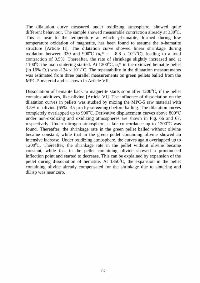
67
The dilatation curve measured under oxidizing atmosphere, showed quitedifferent behaviour. The sample showed measurable contraction already at 330oC.This is near to the temperature at which -hematite, formed during lowtemperature oxidation of magnetite, has been found to assume the -hematitestructure [Article II]. The dilatation curve showed linear shrinkage duringoxidation between 330 and 900oC ( s* = -8.8 x 10⁻⁶/oC), leading to a totalcontraction of 0.5%. Thereafter, the rate of shrinkage slightly increased and at1100oC the main sintering started. At 1200oC, s* in the oxidized hematite pellet(in 16% O2) was -134 x 10-6/oC. The repeatability in the dilatation measurementswas estimated from three parallel measurements on green pellets balled from theMPC-5 material and is shown in Article VII.
Dissociation of hematite back to magnetite starts soon after 1200oC, if the pelletcontains additives, like olivine [Article VI]. The influence of dissociation on thedilatation curves in pellets was studied by mixing the MPC-5 raw material with3.5% of olivine (65% -45 before balling. The dilatation curvescompletely overlapped up to 900oC. Derivative displacement curves above 800under non-oxidizing and oxidizing atmospheres are shown in Fig. 66 and 67,respectively. Under nitrogen atmosphere, a fair concordance up to 1200oC wasfound. Thereafter, the shrinkage rate in the green pellet balled without olivinebecame constant, while that in the green pellet containing olivine showed anintensive increase. Under oxidizing atmosphere, the curves again overlapped up to1200oC. Thereafter, the shrinkage rate in the pellet without olivine becameconstant, while that in the pellet containing olivine showed a pronouncedinflection point and started to decrease. This can be explained by expansion of thepellet during dissociation of hematite. At 1350oC, the expansion in the pelletcontaining olivine already compensated for the shrinkage due to sintering anddDisp was near zero.
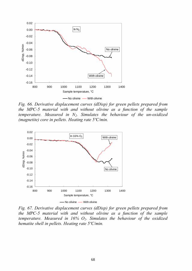
68
-0.16
-0.14
-0.12
-0.10
-0.08
-0.06
-0.04
-0.02
0.00
0.02
800 900 1000 1100 1200 1300 1400
Sample temperature,
dDis
p,%
/min
No olivine With olivine
With olivine
No olivine
In N2
-0.16
-0.14
-0.12
-0.10
-0.08
-0.06
-0.04
-0.02
0.00
0.02
800 900 1000 1100 1200 1300 1400
Sample temperature,
dD
isp
,%/m
in
No olivine With olivine
With olivine
No olivine
In 16% O2
69
3.7.2 Influence of raw material fineness on dilatation (VII)
Dilatation curves for green pellets prepared from the MPC-1 to MPC-5 materialsat constant porosity (31.9%) were measured under non-oxidizing and oxidizingatmospheres. The curves completely overlapped at temperatures below 900oC. s*calculated at 1100oC, 1200 -oxidizing and oxidizing atmospheres, are shown as a function of fineness in Fig.68a-c. The shrinkage rate increased as the raw material became finer at 1100 and1200oC in N2 atmosphere and at 1200 and 1300oC in 16% O2 atmosphere. Thedifference in shrinkage rates under non-oxidizing and oxidizing conditions waslargest at 1100 at this temperature, the main shrinkage in the hematitephase has not yet started. The difference increased as the raw material becamefiner. The large influence of the olivine addition on s* at 130068c. Under N2 atmosphere the olivine addition largely increased the shrinkagerate and under oxidizing atmosphere, the shrinkage rate substantially decreased.
3.7.3 Influence of green pellet porosity on dilatation (VII)
Dilatation curves on green pellets prepared from the coarsest and finest rawmaterials (MPC-1 and MPC-5) with porosities varying between 29 and 33%, weremeasured. The dilatation curves completely overlapped. The dilatation curveswere also measured for green pellets balled from the five MPC materials (MPC-1to MPC-5) at the material specific moisture content (F700, constant plasticity).These dilatation curves overlapped completely, as well.

70
-300
-250
-200
-150
-100
-50
0
64 66 68 70 72 74 76 78 80
Screening %-45
s*x
10-6
,-1
in 16%O2 with olivine in 16% O2
in N2 with olivine in N2
1100
in 16%O2 16%O2
N2N2
(a)
-300
-250
-200
-150
-100
-50
0
64 66 68 70 72 74 76 78 80
Screening %-45
s*x
10-6
,-1
in 16%O2 with olivine in 16% O2
in N2 with olivine in N2
1200
in 16%O2
in N2
16%O2
N2
(b)
-300
-250
-200
-150
-100
-50
0
64 66 68 70 72 74 76 78 80
Screening %-45
s*x
10-6
,-1
in 16%O2 with olivine in 16% O2
in N2 with olivine in N2
1300
N2 N2
in 16%O2 in 16%O2
(c)
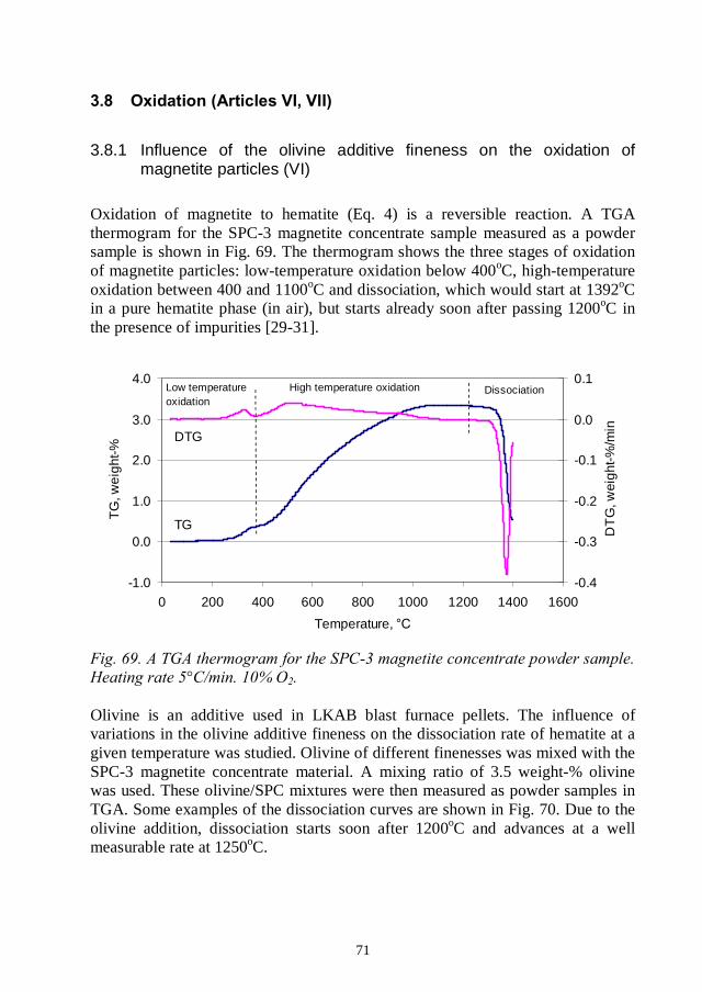
71
3.8.1 Influence of the olivine additive fineness on the oxidation ofmagnetite particles (VI)
Oxidation of magnetite to hematite (Eq. 4) is a reversible reaction. A TGAthermogram for the SPC-3 magnetite concentrate sample measured as a powdersample is shown in Fig. 69. The thermogram shows the three stages of oxidationof magnetite particles: low-temperature oxidation below 400oC, high-temperatureoxidation between 400 and 1100oC and dissociation, which would start at 1392oCin a pure hematite phase (in air), but starts already soon after passing 1200oC inthe presence of impurities [29-31].
-1.0
0.0
1.0
2.0
3.0
4.0
0 200 400 600 800 1000 1200 1400 1600
Temperature,
TG
,wei
ght-%
-0.4
-0.3
-0.2
-0.1
0.0
0.1
DT
G,w
eigh
t-%/m
in
TG
DTG
Low temperatureoxidation
High temperature oxidation Dissociation
Olivine is an additive used in LKAB blast furnace pellets. The influence ofvariations in the olivine additive fineness on the dissociation rate of hematite at agiven temperature was studied. Olivine of different finenesses was mixed with theSPC-3 magnetite concentrate material. A mixing ratio of 3.5 weight-% olivinewas used. These olivine/SPC mixtures were then measured as powder samples inTGA. Some examples of the dissociation curves are shown in Fig. 70. Due to theolivine addition, dissociation starts soon after 1200oC and advances at a wellmeasurable rate at 1250oC.
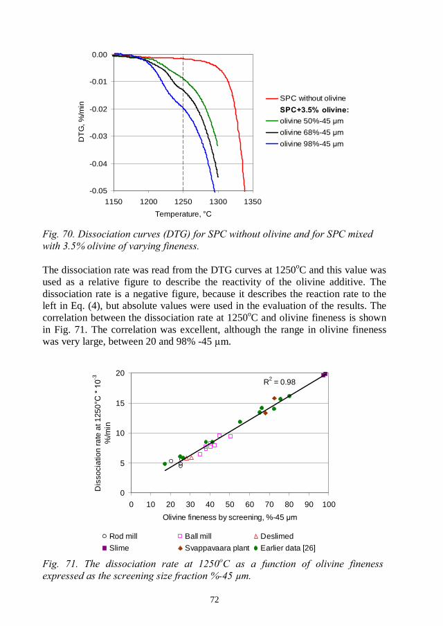
72
-0.05
-0.04
-0.03
-0.02
-0.01
0.00
1150 1200 1250 1300 1350
Temperature,
DT
G,%
/min
SPC without olivine
olivine 50%-45
olivine 68%-45
olivine 98%-45
The dissociation rate was read from the DTG curves at 1250oC and this value wasused as a relative figure to describe the reactivity of the olivine additive. Thedissociation rate is a negative figure, because it describes the reaction rate to theleft in Eq. (4), but absolute values were used in the evaluation of the results. Thecorrelation between the dissociation rate at 1250oC and olivine fineness is shownin Fig. 71. The correlation was excellent, although the range in olivine finenesswas very large, between 20 and 98% -45 .
R2 = 0.98
0
5
10
15
20
0 10 20 30 40 50 60 70 80 90 100
Olivine fineness by screening, %-45
Dis
soci
atio
nra
teat
1250
-3
%/m
in
Rod mill Ball mill Deslimed
Slime Svappavaara plant Earlier data [26]
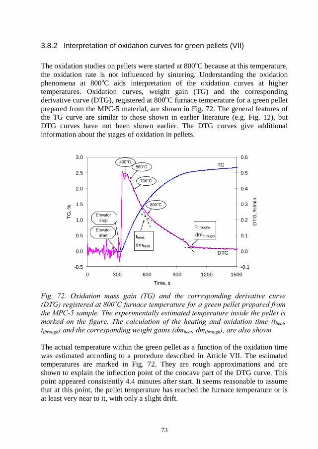
73
3.8.2 Interpretation of oxidation curves for green pellets (VII)
The oxidation studies on pellets were started at 800oC because at this temperature,the oxidation rate is not influenced by sintering. Understanding the oxidationphenomena at 800oC aids interpretation of the oxidation curves at highertemperatures. Oxidation curves, weight gain (TG) and the correspondingderivative curve (DTG), registered at 800oC furnace temperature for a green pelletprepared from the MPC-5 material, are shown in Fig. 72. The general features ofthe TG curve are similar to those shown in earlier literature (e.g. Fig. 12), butDTG curves have not been shown earlier. The DTG curves give additionalinformation about the stages of oxidation in pellets.
-0.5
0.0
0.5
1.0
1.5
2.0
2.5
3.0
0 300 600 900 1200 1500
Time, s
TG
,%
-0.1
0.0
0.1
0.2
0.3
0.4
0.5
0.6
DT
G,%
/min
tthrough,
dmthroughtheat,
dmheat
800
700
560400
Elevatorstart
Elevatorstop
TG
DTG
The actual temperature within the green pellet as a function of the oxidation timewas estimated according to a procedure described in Article VII. The estimatedtemperatures are marked in Fig. 72. They are rough approximations and areshown to explain the inflection point of the concave part of the DTG curve. Thispoint appeared consistently 4.4 minutes after start. It seems reasonable to assumethat at this point, the pellet temperature has reached the furnace temperature or isat least very near to it, with only a slight drift.

74
The calculation of the heating time and the oxidation time (theat, tthrough) andcorresponding mass gains (dmheat, dmthrough) are shown in Fig. 72. It should benoted that here, the oxidation time (tthrough) refers to the total time needed totransfer oxygen through the pellet. The degree of oxidation need not be 100% atthis point. The time delay and mass gain for the isothermal (or near isothermal)oxidation period were also calculated (tiso= tthrough theat , dmiso= dmthrough - dmheat).The average oxidation rate during the isothermal oxidation period was calculatedas dmiso/ tiso. The heating time (theat) was 4.4 ) minutes at 800oC and 3.90.1 (1 ) minutes at 1100 and 1200oC.
The oxidation sequence was also studied by interrupting the oxidation run afterdifferent oxidation times and preparing the pellets to polished samples. Sometypical microscope images are shown in Fig. 73a-f [unpublished]. The oxidationwas interrupted at the minimum on the DTG curve when the sample had reached atemperature of about 400 (a-b), at theat (c-d) and at tthrough (e-f). After reachingthe minimum on the DTG curve a partially oxidized shell of roughly 1 mm inthickness, had formed. The oxidation front was diffuse and the degree ofoxidation was higher in particles on the pellet outer surface (Fig. 73a) comparedto those near to the oxidation front (Fig. 73b). Oxidation mainly to hematiteneedles was seen.
Oxidized areas on the pellet outer surface and near the oxidation front in the pelletinterrupted at theat, are shown in Fig. 73c-d, respectively. Oxidation to bothneedles and single crystals can be seen, the pattern of single crystals being moredominant in areas near the oxidation front. The oxidation front was diffuse. Thethickness of the partially oxidized shell was about 2 mm. Differences in thedegree of oxidation in particles between the pellet outer surface and the oxidationfront seemed to have levelled out somewhat. However, visual judgement of thedegree of oxidation is difficult. Oxidized areas on the pellet outer surface and inthe core of the pellet after interrupting the oxidation at tthrough, are shown in Fig.73e-f. Visually, no difference between the degree of oxidation in particles on thepellet outer surface and in the pellet core, was found. Oxidation throughout thewhole pellet was seen.
The oxidation sequence at 800 is explained as follows.During the non-isothermal heating period (the first 4.4 minutes), a partiallyoxidized shell with a diffuse oxidation front, is formed. As the temperaturecontinuously rises, the capability of particles to take up oxygen within a relevanttime scale (a few minutes) continuously increases. Particles on the periphery ofthe pellet are first in line to fill up with oxygen, while particles further inside thepellet oxidize at a low oxygen pressure. As the temperature in the pellet stabilizes,the degree of oxidation in the partly oxidized shell levels out. Thereafter,isothermal oxidation by diffusion of oxygen through the oxidized hematite shellstarts. At tthrough, the oxidation front has reached the midpoint of the pellet.

75
(a) DTG-min, surface (b) DTG-min, shell
(c) theat, surface (d) theat, shell
(e) tthrough, surface (f) tthrough, core
During oxidation of a pellet, the oxidation rate in magnetite particles should beconsidered in relation to the speed of penetration of the oxidation front. The

76
superficial oxidation of magnetite particles is fast, less than one minute, as wasshown by Monsen [39]. Thereafter, oxidation proceeds by the slow diffusion ofFe2+/Fe3+ ions in hematite [37]. Increasing the temperature facilitates fasterdiffusion through the hematite phase and also the diffusion of O2
- ions [37].Therefore, oxidation in magnetite particles is limited by both their size and by thetemperature. Thermograms measured on sized magnetite concentrate particles areshown in Fig. 74.
-0.5
0.0
0.5
1.0
1.5
2.0
2.5
3.0
3.5
4.0
0 100 200 300 400 500 600 700 800 900 1000 1100 1200
Temperature,
TG
,%
7-9 13-17 24-45 +45
7-9
+45
24-45
13-17
Particles larger than 20 oC. Therefore, the degreeof oxidation in pellets does not reach 100% at this temperature, not even after avery long oxidation time (one hour). At 1100oC, magnetite particles of all sizesfound in typical pellet feeds oxidize to near 100% (within a relevant time scale)and a more distinct oxidation front in pellets is found. At 1200oC, sinteringseverely hinders oxidation and a very clear oxidation front in pellets is formed.This was confirmed by polished samples prepared from pellets obtained fromoxidation runs interrupted at theat, at 1100 furnace temperatures[unpublished]. Some microscope images are shown in Fig. 75a-f.
At 1100magnetite particles were almost completely oxidized (Fig. 75a). Thickness of theoxidized shell formed during the heating period was about 2 mm. Near theoxidation front, mainly oxidation to single hematite crystals was found (Fig. 75b)and bridging in the fine particle fraction could be seen. In the pellet core (Fig.75c), occasional hematite needles were found. At 1200bridging was seen throughout the whole pellet (Fig. 75d-f). On the surface of thepellet and within the oxidized shell, complete oxidation in particles was seen. Theoxidation front was distinct and only a narrow band of partially oxidized particlesat the oxidation front was found. Practically no oxidation in the pellet core (Fig.75f) was found.
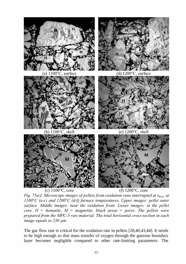
77
(a) 1100 (d) 1200
(b) 1100 (e) 1200
(c) 1100 (f) 1200
The gas flow rate is critical for the oxidation rate in pellets [28,40,43,44]. It needsto be high enough so that mass transfer of oxygen through the gaseous boundarylayer becomes negligible compared to other rate-limiting parameters. The
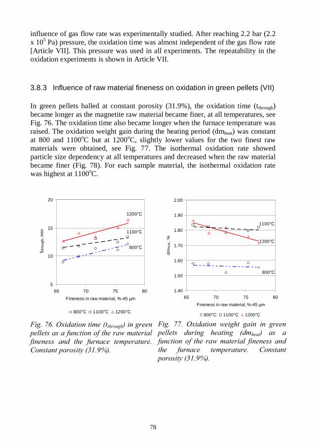
78
influence of gas flow rate was experimentally studied. After reaching 2.2 bar (2.2x 10⁵ Pa) pressure, the oxidation time was almost independent of the gas flow rate[Article VII]. This pressure was used in all experiments. The repeatability in theoxidation experiments is shown in Article VII.
3.8.3 Influence of raw material fineness on oxidation in green pellets (VII)
In green pellets balled at constant porosity (31.9%), the oxidation time (tthrough)became longer as the magnetite raw material became finer, at all temperatures, seeFig. 76. The oxidation time also became longer when the furnace temperature wasraised. The oxidation weight gain during the heating period (dmheat) was constantat 800 and 1100oC but at 1200oC, slightly lower values for the two finest rawmaterials were obtained, see Fig. 77. The isothermal oxidation rate showedparticle size dependency at all temperatures and decreased when the raw materialbecame finer (Fig. 78). For each sample material, the isothermal oxidation ratewas highest at 1100oC.
5
10
15
20
65 70 75 80
Fineness in raw material, %-45
t thro
ugh,
min
800 1100 1200
800
1100
1200
1.40
1.50
1.60
1.70
1.80
1.90
2.00
65 70 75 80
Fineness in raw material, %-45
dmhe
at,
%
800 1100 1200
800
1200
1100
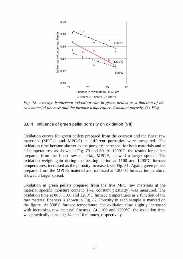
79
0.10
0.12
0.14
0.16
0.18
0.20
65 70 75 80
Fineness in raw material, %-45
Isot
herm
alox
idat
ion
rate
,%/m
in..
800 1100 1200
1100
800
1200
3.8.4 Influence of green pellet porosity on oxidation (VII)
Oxidation curves for green pellets prepared from the coarsest and the finest rawmaterials (MPC-1 and MPC-5) at different porosities were measured. Theoxidation time became shorter as the porosity increased, for both materials and atall temperatures, as shown in Fig. 79 and 80. At 1200 lts for pelletsprepared from the finest raw material, MPC-5, showed a larger spread. Theoxidation weight gain during the heating period at 1100 and 1200temperatures, increased as the porosity increased, see Fig. 81. Again, green pelletsprepared from the MPC-5 material and oxidized at 1200showed a larger spread.
Oxidation in green pellets prepared from the five MPC raw materials at thematerial specific moisture content (F700, constant plasticity) was measured. Theoxidation time at 800, 1100 and 1200raw material fineness is shown in Fig. 82. Porosity in each sample is marked onthe figure. At 800 slightly increasedwith increasing raw material fineness. At 1100 and 1200was practically constant; 14 and 16 minutes, respectively.
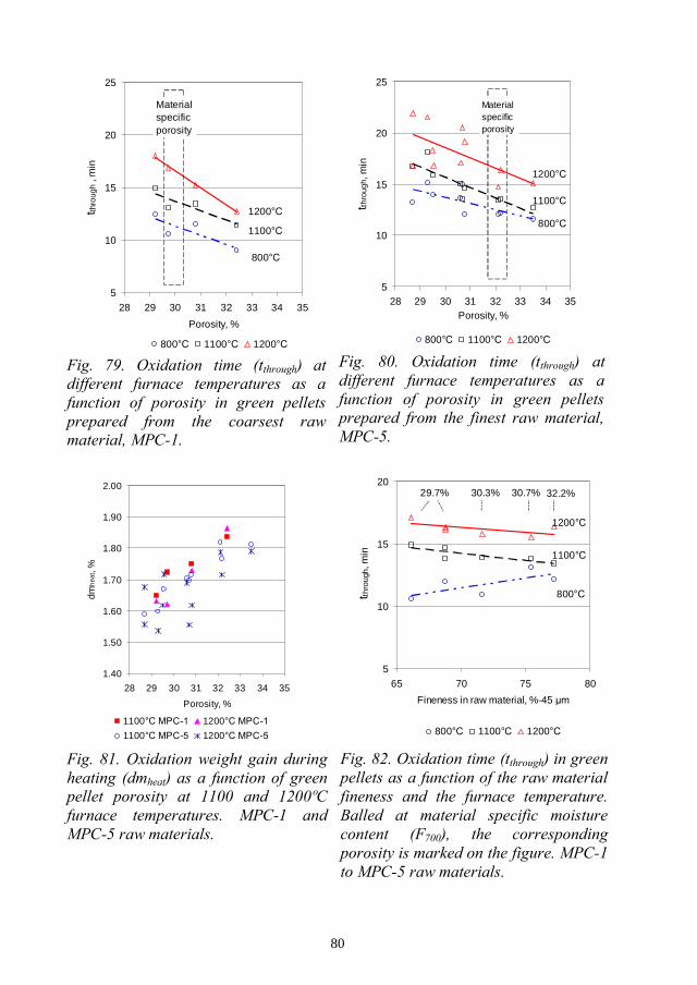
80
5
10
15
20
25
28 29 30 31 32 33 34 35
Porosity, %
t thro
ugh
,min
800 1100 1200
1100
800
1200
Materialspecificporosity
5
10
15
20
25
28 29 30 31 32 33 34 35Porosity, %
tthro
ugh,
min
800 1100 1200
800
1100
1200
Materialspecificporosity
1.40
1.50
1.60
1.70
1.80
1.90
2.00
28 29 30 31 32 33 34 35
Porosity, %
dmh
eat ,
%
1100 1200
1100 1200
5
10
15
20
65 70 75 80
Fineness in raw material, %-45
t thro
ugh,
min
800 1100 1200
800
1100
1200
29.7% 30.3% 30.7% 32.2%
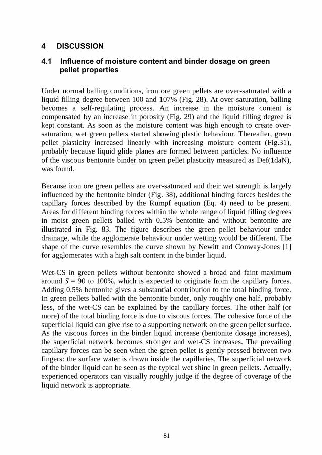
81
Under normal balling conditions, iron ore green pellets are over-saturated with aliquid filling degree between 100 and 107% (Fig. 28). At over-saturation, ballingbecomes a self-regulating process. An increase in the moisture content iscompensated by an increase in porosity (Fig. 29) and the liquid filling degree iskept constant. As soon as the moisture content was high enough to create over-saturation, wet green pellets started showing plastic behaviour. Thereafter, greenpellet plasticity increased linearly with increasing moisture content (Fig.31),probably because liquid glide planes are formed between particles. No influenceof the viscous bentonite binder on green pellet plasticity measured as Def(1daN),was found.
Because iron ore green pellets are over-saturated and their wet strength is largelyinfluenced by the bentonite binder (Fig. 38), additional binding forces besides thecapillary forces described by the Rumpf equation (Eq. 4) need to be present.Areas for different binding forces within the whole range of liquid filling degreesin moist green pellets balled with 0.5% bentonite and without bentonite areillustrated in Fig. 83. The figure describes the green pellet behaviour underdrainage, while the agglomerate behaviour under wetting would be different. Theshape of the curve resembles the curve shown by Newitt and Conway-Jones [1]for agglomerates with a high salt content in the binder liquid.
Wet-CS in green pellets without bentonite showed a broad and faint maximumaround = 90 to 100%, which is expected to originate from the capillary forces.Adding 0.5% bentonite gives a substantial contribution to the total binding force.In green pellets balled with the bentonite binder, only roughly one half, probablyless, of the wet-CS can be explained by the capillary forces. The other half (ormore) of the total binding force is due to viscous forces. The cohesive force of thesuperficial liquid can give rise to a supporting network on the green pellet surface.As the viscous forces in the binder liquid increase (bentonite dosage increases),the superficial network becomes stronger and wet-CS increases. The prevailingcapillary forces can be seen when the green pellet is gently pressed between twofingers: the surface water is drawn inside the capillaries. The superficial networkof the binder liquid can be seen as the typical wet shine in green pellets. Actually,experienced operators can visually roughly judge if the degree of coverage of theliquid network is appropriate.
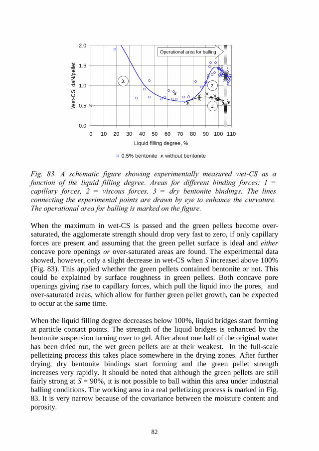
82
0.0
0.5
1.0
1.5
2.0
0 10 20 30 40 50 60 70 80 90 100 110
Liquid filling degree, %
Wet
-CS
,da
N/p
elle
t
0.5% bentonite without bentonite
Operational area for balling
2.
1.
3.
When the maximum in wet-CS is passed and the green pellets become over-saturated, the agglomerate strength should drop very fast to zero, if only capillaryforces are present and assuming that the green pellet surface is ideal andconcave pore openings over-saturated areas are found. The experimental datashowed, however, only a slight decrease in wet-CS when increased above 100%(Fig. 83). This applied whether the green pellets contained bentonite or not. Thiscould be explained by surface roughness in green pellets. Both concave poreopenings giving rise to capillary forces, which pull the liquid into the pores, andover-saturated areas, which allow for further green pellet growth, can be expectedto occur at the same time.
When the liquid filling degree decreases below 100%, liquid bridges start formingat particle contact points. The strength of the liquid bridges is enhanced by thebentonite suspension turning over to gel. After about one half of the original waterhas been dried out, the wet green pellets are at their weakest. In the full-scalepelletizing process this takes place somewhere in the drying zones. After furtherdrying, dry bentonite bindings start forming and the green pellet strengthincreases very rapidly. It should be noted that although the green pellets are stillfairly strong at = 90%, it is not possible to ball within this area under industrialballing conditions. The working area in a real pelletizing process is marked in Fig.83. It is very narrow because of the covariance between the moisture content andporosity.
83
The increase in Wet-CS as a function of the bentonite dosage (Fig. 38) has beenshown in earlier literature [4], but the binding mechanisms have not beendiscussed earlier. Two distinct ranges were found. At low bentonite dosages thebinding force is suggested to be a combination of the capillary force and thecohesive force due to the viscous binder, as described earlier. Their relativecontribution depends on the binder dosage. As the bentonite dosage passes theinclination point at around 0.5%, the cohesive force (viscosity) still increases, butthe adhesion of the binder liquid on the particle surfaces could become weakerand start controlling the green pellet breakage. According to this approach, theadhesion of the binder liquid to particle surfaces would dictate how much of theincrease in viscosity can be utilized to build up the green pellet wet compressionstrength. Fibrous structures in bentonite would be expected to further increase thegreen pellet wet strength, as was shown experimentally by Kawatra and Ripke[19,20].
Based on the binding mechanisms described above, a new mechanism for greenpellet growth is suggested. Two limiting parameters are identified. Firstly, thegreen pellet plasticity needs to exceed a minimum level to enable growth. Thislimiting plasticity defines the moisture content needed in balling. Secondly,viscosity in the liquid phase needs to be such that the superficial water on thegrowing green pellet and on the free pellet feed can coalesce within the timeavailable during collision.
Drop number values depended on changes both in the moisture content and in thebentonite dosage (Fig. 44 and 45). The linear increase in the drop number withincreasing moisture content can be explained by the simultaneous increase inplastic deformation (Fig. 30). The increase in the drop number with increasingbentonite dosage is probably due to increasing elasticity. This change in elasticityis not seen in Def(1daN) because of the much lower shear rate applied in this test.Therefore, Def(1daN) and the drop number only correlate if the bentonite dosageis kept constant. Bentonite also shifts the flooding point, at which the greenpellets deform under their own weight, towards higher moisture contents.
Dry-CS was independent of the original moisture content in green pellets (Fig.48), even if the studied range in moisture (and porosity) was very large comparedto normal variations in balling. Dry-CS was completely controlled by the amountof bentonite added (Fig. 49). This result shows that an increase in porosity, assuch, need not be harmful for dry-CS. However, if the increase in porosity takesplace through air bubbles trapped in the green pellet structure, the pellets canbecome very weak as will be discussed in Chapter 4.5.
84
Saturations above 100% are quite contradictory to earlier published data [3-7],which assume flooding at = 100% and fully developed capillary forces at =90%. A certain shift in could have been caused by different methods used inporosity determination. Porosity is calculated by subtracting the volume ofparticles from the volume of the green pellets. The volume of particles is welldefined and calculated from the sample weight and the absolute density of theparticles. However, the volume of green pellets depends on how the borderline onthe green pellet surface is defined how much of the surface roughness isconsidered to belong to the green pellet pore structure. In this study, the limit wasset in such a way that the pore structure ends as the pore openings become largerthan 9as was done by Rumpf [7], the measured porosity will naturally be larger and inall cases < 100%.
Some air was found in all studied green pellets. In the presence of surface-activeagents, the amount of air could be considerable. Air bubbles in green pellets makethe concept of the liquid filling degree more complex. Liquid filling degree is alsocalled . These two names for the same parameter fairly welldescribe its dual meaning. If part of the pore volume is filled with air bubblesinstead of water, calculated from Eq. (1) becomes < 100% and theis low. However, the green pellets can still be in the sense that thegreen pellet surface is wet, which is a pre-assumption for the green pellets togrow. A situation where the pellets are truly under-saturated arises when there istoo little water available in balling to fill the pores when particles are fullypacked. In that case, binding by liquid bridges would take place and pellets wouldbe in the funicular state. During micro-balling, pellet growth can be forced evenin such situations. In full-scale balling this situation is not likely to happen,because it would result in an increase in the recycling loads of the balling circuitsand would be compensated by adding more water.
As described earlier, in iron ore green pellets, the liquid filling degree undernormal balling conditions is constant. The calculation of the liquid filling degreeis a good way to estimate the amount of air in green pellets, but does notnecessarily describe the prevailing binding mechanisms (pendular, capillary ordroplet states) in the way commonly presented in earlier literature [1,4,6,7] andas shown in Fig. 2. Also, the filling degree does not reveal the optimum moisturecontent in balling as suggested in earlier literature [3,4,6].
85
A definition for the optimum moisture content in balling is introduced. It can bedefined in terms of plasticity in green pellets. The moisture content that results in700 , F700, is regarded as the optimum moisturecontent, because this level of plasticity was found in green pellets produced infull-scale balling. At F700, about half of the green pellets showed the C-typebreakage pattern (Fig. 32 with F700 = 9.0%) typical for breakage through plasticflow. A lower degree of plasticity would lead to increasing circulating loads andsurging in the balling circuits. Moisture contents higher than F700 would increasethe green pellets growth rate and reduce surging in the balling circuits, but theincrease in green pellet plasticity would also reduce the permeability of the pelletbed in the drying zones. The optimum running conditions are chosen by balancingthese advantages and disadvantages against each other.
The results show that as the raw material becomes finer, an increasing amount ofwater is needed to keep the plasticity constant. Variations in F700 were betterdescribed by the large particles (%-45 -13 r thespecific surface area). Best correlation to F700 values was obtained using the slopeof the particle size distribution, here expressed as a difference between the sizefractions %-45 -13 (Fig. 37). If the slope increases, more water isneeded in balling. The raw material fineness analysis in Table 1 shows thatvarying the mill feed rate causes only relatively small changes in the %-13fraction (expressed in mass per cent), compared to changes in the %-45fraction. This explains why the correlation lines drawn for the MPC and SPCsamples were closer to each other when F700 was drawn against %-4536) than the corresponding lines drawn against specific surface area (Fig. 35).Naturally, if the process variations in the slope of the particle size distribution aresmall, F700 can be predicted by only measuring the %-45assumption is actually made today, because the grinding of MPC and SPC pelletfeeds is controlled by the %-45 , exclusively.
For good ballability, the specific surface area in pellet feeds (at LKAB) shouldexceed around 9,500 cm2/cm3. Therefore, the -45needs to be chosen so that this threshold value is exceeded. Thereafter, themoisture content needs to be adjusted to give the desired degree of plasticity ingreen pellets. Probably, the most detrimental factor for a balling process would becontinuous in fineness. The moisture content in balling would bealternately too high and too low compared to the F700 of the incoming pellet feed.
Judgement as to whether balling is running is recommended to bebased on green pellet plasticity and compression strength, instead of using therather inaccurate drop number. The balling process can be controlled by adjusting
86
the moisture content (plasticity) or by adjusting the bentonite dosage (viscosity).These two operations are not interchangeable. Even if they would compensate ingrowth rate, as suggested by the ballability index (see Eq. 3 and Fig. 9), the greenpellet properties would differ.
The above described interpretation of the plasticity values requires that the liquidfilling degree isdeformation would rather imply the presence of air inclusions than a too lowmoisture content, as will be described later in Chapter 4.5.
The Rumpf equation (Eq. 4) claims that the agglomerate wet strength increases asthe raw material becomes finer. This was, indeed, confirmed by green pelletsballed without bentonite binder (Fig. 43). The results resemble the data shown inearlier literature, see Fig. 4 and 5 [4,10]. This increase in wet-CS can be explainedby an increase in the capillary forces as the capillaries become smaller, accordingto Eq. (4).
However, in green pellets balled with 0.5% of the bentonite binder and(i.e., under realistic balling conditions), wet-CS was constant
and independent of the raw material fineness (Fig. 41). In this case, theagglomerate strength is mainly controlled by the viscous forces and Eq. (4) doesnot apply. This means that low wet-CS values cannot be compensated by furthergrinding of the raw material. For process control purposes, it is also important tobe aware that changes in the raw material fineness would not show in wet-CS(presuming that plasticity and the bentonite dosage are constant). The results alsoshow that the general statement of broader particle size distributions resulting inincreasing pellet wet strength [3-6], did not apply. Broader particle sizedistributions (MPC samples) indeed showed lower porosity in pellets, but becausewet-CS is mainly controlled by the viscous forces in the binder liquid, a lowerporosity does not contribute to the wet-CS values. Broader particle sizedistributions can, however, have an influence on nucleation and the green pelletgrowth rate in balling circuits. These studies were outside the scope of this thesis.
A comparison of wet-CS values and with 0.5% bentonitewould lead to incorrect conclusions (Fig. 42). If the moisture content is slightlylower than F700 for the specific material, wet-CS is at maximum (as in the SPCsamples), but green pellets would be too dry for large-scale balling. If themoisture content is larger than F700 (as in the MPC-1 and MPC-2 samples), greenpellets would become weaker due to their higher plasticity.

87
Dry-CS showed no correlation to magnetite concentrate fineness within thestudied range. The drop number seemed to increase slightly, when the specificsurface area in the magnetite raw material increased (Fig. 47). This might beexplained by an increase in the viscous forces caused by the increasing amount offine particles. However, the drop number is a fairly inaccurate figure and it ishighly dependent on the amount of the bentonite binder (Fig. 45). An increase inthe magnetite concentrate fineness might give a positive contribution to the dropnumber values, but the differences are so small that they could easily be coveredunder normal variations in the bentonite dosage or in the bentonite quality. A dropnumber around four is usually considered necessary for the green pellet durabilityduring reloading from one conveyor belt to another. A drop number larger thanthat would not be of any use.
Additions of the surface-active flotation collector reagent, Atrac, on pellet feedsbefore balling were found to lead to serious degradation in green pellet strength(Fig. 52-55). In the presence of the Atrac reagent, air bubbles attached so stronglyin the green pellet structure that they could not be removed during balling. Greenpellets became very weak both in wet and dry states and showed multi-breakagepatterns. Breakage to several crumbs can explain the increased generation of dustobserved at the pelletizing plant [16,17]. The green pellet plasticity increasedbecause the air bubbles behaved like large plastic particles.
The best way to detect that Atrac is carried over to the pelletizing plant is tomeasure the green pellet porosity and the moisture content and to calculate thefilling degree. This simple measure helps the process operators to find the correctsource of disturbance, which can otherwise be difficult because of the complexnature of the balling process. Because the calculation of the filling degree is verysensitive to changes in porosity, high accuracy, or at least high repeatability, inthe porosity measurement is essential. The development work described in ArticleI has resulted in stable and repeatable porosity values at LKAB laboratories.
The obtained experimental results could not be fitted with the Rumpf equation(Eq. 2) because the liquid-solid contact angles as a function of Atrac additions arenot known. However, the breakage follows the weakest path and the breakagepatterns recorded by the high-speed camera did suggest crack growth along thepore structures rather than breakage through the loss of the capillary forces.Further grinding of the magnetite concentrate is not expected to make the greenpellets stronger, but could result in an opposite effect, because of the increasedparticle surface area exposed to Atrac adsorption.
88
The negative influence of Atrac on balling gradually decreased during storage(Fig. 62,63). The recovery time was influenced by the amount of Atrac present inthe pellet feed being about one day for Atrac additions of 20 g/t and around oneweek for Atrac additions of 60 g/t. Even if the principal reasons for thisrestoration of the balling behaviour is not known today, it can be utilized forprocess control. In case of Atrac carry-over to the pelletizing plant, the correctiveprocess control measures would be to revise the function of the homogenizingstorage to maximize the throughput time and to revise the status of the flotationprocess. The reagent dosages should be kept at the lowest possible level at alltimes. Another conclusion of practical importance is that flotated pellet feeds needto be regarded as materials, at least for some days after flotation. Thisneeds to be considered when flotated pellet feeds are sampled for ballingexperiments or for pot grate tests. If a stable sample material is required, it shouldbe stored for a few weeks before balling. The desired surface properties can thenbe created by controlled reagent additions just before balling.
When a pellet starts to oxidize, a shell of hematite is formed while the core of thepellet is still magnetite. Dilatation curves were measured under non-oxidizing andoxidizing atmospheres to separately describe thermal volume changes in thesetwo phases. The dilatation curve observed under nitrogen atmosphere is used todescribe the behaviour of the magnetite core in pellets. The dilatation curveobserved under oxidizing atmosphere is used to describe the behaviour of theoxidized hematite shell in pellets.
These two phases showed very different thermal volume changes (Fig. 64 and65). The un-oxidized magnetite core showed thermal expansion up to 800oC,while contraction by 0.5% during oxidation between 330 and 900oC, wasobserved. After 800oC, the magnetite core started to shrink slightly and soon after950oC, it shrank much faster than the hematite shell, because the main sintering ofthe hematite shell started only after passing 1100oC. Due to the higher shrinkagerate in the pellet core compared to the oxidized shell, the core is pulled away fromthe shell and the duplex structure starts to form. At 1200oC the shrinkage rates inthe magnetite core and in the hematite shell were near equal.
These thermal volume changes cause structural stress in pellets and, in the worstcase, concentric cracks along the structural boarder between the more heavilysintered core and less sintered shell (duplex structure). After sintering in the kilnand cooling in the cooler, practically all magnetite is oxidized to hematite, but thedifferences in the pellet macro-structure remain, as was shown recently in a widestudy of macro-structures in plant pellets [38]. The remaining structural stress inpellets can be released upon reduction in the blast furnace and result in fracturing

89
to pieces and fines. Ilmoni and Uggla [40] found that the degree of oxidationneeds to be at least 80% in pellets leaving the PH zone to get acceptable strengthin pellets after firing. When the oxidized shell is pushed further inside the pelletbefore final sintering in the kiln, the contact area between the core and the shelldecreases, as does the structural stress.
Dilatometer measurements showed that the shrinkage rate increased as the rawmaterial became finer at 1100 and 1200oC for the magnetite core (in N2) and at1200 and 1300oC for the oxidized shell (in 16% O2), see Fig. 68. The difference inshrinkage rates between these two phases was largest at around 1100oC andincreased as the magnetite concentrate raw materials became finer. A finer grindin the raw material would, therefore, promote the formation of the duplexstructures. The sintering rate was not influenced by the original porosity in greenpellets, within the studied range (between 28 and 34%). Contraction duringoxidation between 330 and 900oC was not influenced by the original porosity inpellets or by the magnetite concentrate fineness.
The measured differences in the sintering rate as a function of raw materialfineness were, however, small compared to the large influence of the olivineadditive found soon after passing 1200oC. Dilatation measurements showed thatdissociation of hematite back to magnetite gave rise to an increase in volume ofthe oxidized hematite shell. At the same time, the sintering rate of the magnetitecore was further increased (Fig. 66 and 67). Therefore, if the temperature fordissociation in pellets is exceeded, the risk of formation of concentric cracks isenhanced. In that case, the structural stress in pellets is expected to be mainlycontrolled by the rate of dissociation (temperature, the amount and fineness of theadditive) rather than by the fineness of the magnetite concentrate. Interactionsbetween the magnetite concentrate and olivine additive fineness could occur. Inthe present work, the influence of olivine on thermal volume changes in iron orepellets is only qualitatively shown. For quantifying these effects, more laboratorywork is needed.
When a 10-mm pellet was heated by placing it in a hot furnace at 800 to 1200oC,roughly half of the pellet mass was oxidized under non-isothermal conditions,during the heating period. When the temperature inside the pellet reached thefurnace temperature, isothermal (or at least near isothermal) oxidation started. Theoxidation time (time needed to transport oxygen through the whole pellet)increased and the isothermal oxidation rate correspondingly decreased as themagnetite concentrate raw material became finer, at all furnace temperatures (Fig.76 and 78). At 800oC this can be explained by an increase in the degree ofoxidation of the magnetite particles, which is limited by the particle size at this
90
temperature. Decreasing the particle size simply increases the consumption ofoxygen. At 1100oC, magnetite particles of all sizes found in typical pellet feedsoxidize near completely, within a relevant time interval (a few minutes).Therefore, at 1100 and 1200oC furnace temperatures the underlying mechanismsneed to be different.
At 1100oC, the increase in the oxidation time as the magnetite concentrate becamefiner cannot be explained by enhanced sintering of the oxidized hematite shell,because at this temperature, the main sintering in the hematite phase has not yetstarted. Also, no difference in shrinkage during the formation of the hematite shell(oxidation between 330 and 900oC) as a function of the raw material fineness wasfound. Therefore, at 1100oC the logical explanation to the particle sizedependency of the oxidation time is the increased sintering in the magnetite core,taking place and suppressing then the diffusion rate of oxygen.
At 1200oC, the hematite shell and the magnetite core both show vigoroussintering and the sintering rate in both phases increased as the magnetiteconcentrate became finer (Fig. 68). Therefore, at 1200oC, the oxidation ratebecomes limited both by the decreased diffusion rate through the oxidizedhematite shell being sintered and by the sintering in the magnetite core takingplace before oxidation. This dual mechanism explains why the oxidation rate at1200oC was appreciably lower compared to oxidation at 1100oC. At 1200oC, thesuppressing effect of sintering on oxidation became so severe in green pelletsballed from the two finest raw materials that the oxidation weight gain started tolag behind already during the heating period (Fig. 77). The results show that thetemperature range for optimal oxidation is very narrow, between 1100 and1200oC. 1100oC is the temperature needed for complete oxidation in particles andsoon after 1200oC the increasing dissociation pressure and severe sintering in boththe oxidized hematite shell and in the magnetite core slow down the oxidationrate.
In the experiments described above, the green pellet porosity was kept constantwhile the particle size in the pelletizing raw material was varied. In theseexperiments, the diffusion rate of oxygen before sintering started, was constant.As describe earlier, finer raw materials demand a higher moisture content inballing, which results in a higher porosity in green pellets. No differences in thesintering behaviour at different levels of original green pellet porosity were foundand therefore, increasing the original green pellet porosity should result inincreasing oxidation rates throughout the whole oxidation process. This wasconfirmed by the experimental results (Fig. 79 to 81). The oxidation timedecreased and the amount of oxidation taking place during the heating periodincreased as porosity increased. Green pellets prepared from the finest rawmaterial (MPC-5) showed, however, a substantial spread in the results at 1200oCfurnace temperature. Samples that showed long oxidation times showed also lessoxidation during heating. This could be explained by the subtle balance between
91
oxidation and sintering. Even a slight decrease in the initial oxidation rate due to,for example, small differences in porosity, would leave more time for sinteringbefore oxidation and further decrease the oxidation rate.
Oxidation rate in green pellets prepared from the five MPC materials underrealistic balling conditions (F700, constant plasticity) showed that in the laboratoryoxidation experiments the decrease in the oxidation rate due to the finer grind inthe raw material was levelled out by the opposite effect of an increase in porosity.In green pellets balled at constant plasticity and oxidized at 1100temperature, the oxidation time was constant (14 minutes, Fig. 82). In the realpelletizing process, the situation would, however, be different. Only partialoxidation takes place in the PH zone before pellets are loaded in the kiln.Therefore, even if the oxidation rate in the green pellets were the same until theend of the PH zone, more sintering in the kiln would take place in green pelletsprepared from the finer materials. This would result in enhanced duplex structuresas the raw material becomes finer. Also, the spread in the degree of duplexstructures can be expected to increase. The results highlight the complexity of theoxidation and sintering process and the importance of process knowledge whenlaboratory data is used to predict pellets behaviour in the full-scale process.
In these experiments, the real temperature inside the pellet was not measured. Asthe oxidation of magnetite to hematite is a largely exothermic reaction, atemperature rise inside the pellet can be expected. If the temperature inside thepellet rises, it is expected to happen during the fast oxidation of the pellet outershell and can have a large influence on the oxidation rate. If the temperatureinside the pellet exceeds the limiting temperature for dissociation to start, theoxidation and dilatation patterns would be substantially changed. For furtherunderstanding of the oxidation and sintering patterns, a fast and accuratetemperature measurement would be needed.
The oxidation rate in pellets is not only controlled by the pellet properties but alsoby process parameters applied in the pellet plant. One of the most importantprocess variables regarding the oxidation rate is the heating rate of pellets, as wasalso pointed out by Haas et al. [44]. In the present work, the temperature rise wasaround 300oC/min, calculated as an average for the whole heating period. In thereal process, the heating rate is roughly the same for the upper part of the pelletbed, while the heating rate for pellets in the bottom of the bed is lower (about150oC/min). The rate of heating applied in the TPH and PH zones needs to beadjusted for the specific raw material and green pellet properties, like fineness ofthe magnetite concentrate and the additive, porosity in green pellets and theoxygen content in the oxidizing gas. A lower heating rate allows the formation ofa thicker hematite shell before the sintering temperature is reached. The degree ofoxidation in pellets when leaving the PH zone should preferably be above 80%[40], on average for the whole bed of pellets. Obviously, it would be difficult tocompensate for fast fluctuations in green pellet properties in induration. In
92
pelletizing, consistency in all parameters is a fundamental requirement for stableproduct quality.
In this work, the size of the studied green pellets was limited by the graphitefurnace in the TGA instrument to 10 mm. Industrial green pellets are normallylarger. The size of green pellets can be expected to have a large influence on theformation of duplex structures. As the green pellets become larger, the size of theun-oxidized magnetite core subjected to sintering before oxidation increases.
Some other process parameters can influence the oxidation of iron ore pellets, aswell. Large sensitivity of the oxidation rate to variations in the partial pressure ofoxygen has been reported [28,43]. The oxidation results obtained with differentgas flow rates [Article VII] visualize the fact that if the gas flow in the bed ofpellets is hindered by, for example, crumbs from broken pellets or by deformationof over-wetted green pellets, it has an essential influence on the oxidation process.
The repeatability in the experimental test work has been reported in respectivearticles. Some sources of experimental errors are further discussed below.
In micro-balling, as performed in this thesis, green pellets with largely deviatingporosity and moisture content can be produced. It is a suitable method forstudying green pellet properties with different raw material mixtures. However,the green pellet cannot be predicted by this kind of ballingexperiments. Also, in micro-balling, the green pellet growth takes place mainly bylayering. In a full-scale production plant pellet growth takes place by coalescence,as well. Therefore, differences between plant green pellets and micro-balled greenpellets can occur. The principal mechanisms regarding the green pellet propertiesare, however, the same.
When highly plastic wet green pellets are measured in the Pellet Multi Press,some deformation can take place as soon as the green pellet is placed on thesample tray. Therefore, the measured green pellet plasticity values (Def(1daN))could be systematically somewhat too low. The measurements are, however,consistent and this eventual deviation would not change the interpretation of theresults reported in this thesis.
The compression force in the Pellet Multi Press instrument is regularly calibratedagainst a certified load cell. The calibration correction for the load cell has beennegligible compared to other experimental errors. Also, in each micro-balling testseries, a relevant reference sample has been balled and characterized.
93
The magnetite concentrate materials (MPC-1 to MPC-5 and SPC-1 to SPC-6, seeTable 1) were homogenized before packing into barrels. However, the samplesare authentic materials from the concentrating plants and some quality variationsmay occur. Contact angle measurements on these materials were not available.All materials were stored during at least one year before balling. The sizing datain Table 1 shows average values for five or more analysis samples taken fromdifferent batches used in micro-balling. The calculated standard errors (2 n,where n is the number of parallel samples) were 90 cm2/cm3 for the specificsurface area and 1 %-units for the %-45 by screening and for the%-13 measured by the cyklosizer.
Porosity is measured in the GeoPyc instrument as an for a batch of greenpellets (100 g, appr. 25 pellets). Variations in porosity between individual pelletscan occur. Differences in porosity between the pellet core and shell can occur, aswell. Green pellets can even contain hidden cracks. In the oxidation experiments,only one pellet can be measured at a time and the porosity is assumed to be theaverage value obtained from the GeoPyc measurement. This variation is includedin the estimated repeatability for the oxidation measurements shown in ArticleVII.
Preparing the green pellets to constant size by rotating them in a 10-mm hole, asdescribed in Article VII, could slightly loosen up the outer particle layers on thegreen pellets. In that case, the measured initial oxidation rates could be slightlytoo high, but would not change the conclusions regarding the oxidation andsintering mechanisms described in Article VII.
The pressure of the oxidizing gas in the TGA measurements was chosen to be 2.2bar (2.2 x 10⁵ Pa). At this pressure, the gas flow rate might still have a smallinfluence on the oxidation rate [Article VII]. The gas pressure was, however,limited by the design of the graphite furnace in the TGA 92-16 instrument andcould not be further increased. This possible effect would make the measuredoxidation times somewhat too long, but would not change the interpretation of theoxidation results.

94
The results showing the negative influence of finely ground olivine particles onthe oxidation of magnetite [Article VI] were applied at the LKAB Svappavaarapelletizing plant, starting from spring 2001. The control value for olivine grindingwas decreased from 72 to 65% -45 . The top-size control was accomplished byclosing the grinding circuit with a hydro cyclone. No problems with green pelletstrength were experienced. The low-temperature reduction strength (LTD, ISO13930) measured on sintered pellets sampled on a daily basis at the pelletizingplant showed an increase from 92 2 to 95 1 (1 ) %+6.3 mm. This can beconsidered a marked improvement. This improvement in LTD values was at firstinterpreted to be exclusively due to the faster oxidation in the grate because of alower dissociation pressure. Later, as the dilatation results were obtained, itbecame clear that the large thermal volume changes associated with thedissociation of hematite also contribute to and enhance the duplex structures inpellets. In addition to the improvements in pellet quality, the coarser grind forolivine made it possible to increase the throughput of the olivine grinding circuitwith relatively small investments.
Today, micro-balling is an essential part of the continuous research work atLKAB. Three people are employed full-time to do the laboratory work. Two moreresearchers have been employed to work within this research area. The PelletMulti Press instrument has been tested for process control purposes and today,three instruments are in continuous use at LKAB.
Both practical and theoretical training courses for different occupational groups atLKAB have been arranged on a regular basis to spread the new knowledge gainedduring the course if these studies. Compendiums describing green pelletproperties have been prepared.

95
1. The capillary theory predicts that wet agglomerates can be made stronger byfurther grinding of the raw materials. Further grinding should also compensate forproblems with wetting or surface tension. Furthermore, the capillary theorypredicts that wider particle size distributions in the raw materials would result instronger agglomerates, because they pack to a lower porosity. Within the limitscovered in this work, the capillary theory did not describe the green pelletbehaviour when balling was done by using the viscous bentonite binder. Thefindings leading to this conclusion are specified below.
2. A new measuring method for green pellet plasticity was developed. Theoptimum moisture content in balling was defined as the moisture content resultingin a given degree of plasticity in green pellets. Too much plasticity would reducethe permeability of the pellet bed during drying and oxidation with negativeconsequences for both the pelletizing capacity and the pellet quality. If the greenpellets are not plastic enough, they become fragile and would lead to increasedcirculating loads and surging in the balling circuits.
3. The optimum moisture content in balling is largely dependent on the slope ofthe particle size distribution in the raw materials. Pellet feeds with steeper particlesize distributions require more water in balling and thus result in larger porosity ingreen pellets. Continuous variations in the raw material fineness would result inalternately too high and too low moisture content compared to the properties ofthe incoming raw material. This would cause fluctuations in both balling andinduration.
4. Green pellet properties with varying raw material fineness should be comparedat constant plasticity, instead of comparing at constant moisture content as hascommonly been done in earlier literature. Wet compression strength measured ingreen pellets balled at constant plasticity and with 0.5% of the bentonite binder,was not influenced by the raw material fineness. This is because the wet strengthis mainly controlled by the viscous forces of the binder liquid. Raw materialfineness could, however, influence the nucleation and growth rate in balling. Drystrength was not influenced by the raw material fineness or the green pelletporosity; unless the green pellets contained entrapped air bubbles. Dry strengthwas completely controlled by the amount of the bentonite binder.
5. A marked degradation in green pellet mechanical strength both in wet and drystates was found in the presence of a surface-active flotation collector reagent.This loss in green pellet quality was explained by a strong attachment of airbubbles in the green pellet structure. High-speed camera images showed multi-breakage patterns, which explains the increased generation of dust observed at the
96
pellet plant. The breakage follows the weakest path. Breakage took place by crackpropagation between the air bubbles, rather than through a loss of the capillaryforces. The negative effects of the flotation collector reagent on agglomerationdiminished during storage of the pellet feed. The results emphasize theimportance of minimizing the reagent dosages in flotation and maximizing theresidence time of the pellet feed in the homogenizing storage before balling.
6. The dilatation measurements showed contraction during oxidation in greenpellets balled with 0.5% bentonite. Total shrinkage during oxidation between 330and 900oC was 0.5%. This shrinkage was not influenced by the raw materialfineness or the original porosity in pellets. Simultaneously with the contractionduring formation of the hematite shell, thermal expansion in the un-oxidizedmagnetite core was measured. Sintering started earlier in the magnetite core(950 shell (1100 . The sintering rate increasedwith increasing fineness in the magnetite concentrate. The difference in sinteringrates between the magnetite core and the hematite shell was largest at 1100 andincreased with increasing fineness in the magnetite concentrate. A finer grind inthe raw material would, therefore, promote the formation of the un-wanted duplexstructures with a more heavily sintered core pulling off from the shell.
7. Combining the results from the oxidation and dilatation studies revealed newinformation about the rate limiting factors in oxidation of iron ore pellets. At1100oC, the diffusion rate of oxygen was limited by sintering in the magnetitecore, taking place oxidation rather than by the diffusion rate of oxygenthrough the oxidized hematite shell, as has been claimed in earlier literature. Theoxidation rate was at maximum at around 1100oC. At 1200oC, the rate ofoxidation substantially decreased because both the hematite shell and themagnetite core show heavy sintering at this temperature. The results illustrate thatthe temperature range for optimal oxidation is very narrow. 1100oC is thetemperature required for complete oxidation in particles and soon after 1200oCthe increased dissociation pressure and severe sintering slow down the oxidationrate.
8. At constant porosity in green pellets, the oxidation time increased as themagnetite concentrate became finer, because of the enhanced sintering. Inpractical balling, however, the increase in fineness would necessitate the use ofmore water in balling, which results in an increase in green pellet porosity. In thelaboratory oxidation measurements, these two opposite effects levelled out andthe oxidation time became constant when green pellets were balled at constantplasticity, i.e. under realistic balling conditions. However, in a full scalepelletizing process, differences in the duplex structure would still be expected.This is because pellets are only partially oxidized before sintering in the kiln andsintering was enhanced by a finer grind in the magnetite concentrate rawmaterials.

97
9. Olivine, which is used as an additive in LKAB blast furnace pellets, was foundto initiate the dissociation of hematite back to magnetite already at temperaturesthat can occur during oxidation in the PH zone. The rate of dissociation waslargely influenced by the olivine fineness. If the dissociation temperature isexceeded, the resulting decrease in oxidation rate would increase the size of theun-oxidized core exposed to sintering before oxidation. Also, dilatometermeasurements showed opposite thermal volume changes in the oxidized hematiteshell and in the magnetite core in the presence of olivine. Dissociation caused alarge volume increase in the oxidized hematite shell, while the olivine additionfurther enhanced the sintering of the magnetite core. These mechanisms lead toincreased structural stress between the hematite shell and the magnetite core.
10. The knowledge about the negative influence of finely ground olivine on theoxidation in pellets was applied at the LKAB Svappavaara pelletizing plant. Thecontrol value for the grinding of olivine was decreased from 72 to 65 % -45The pellet low-temperature reduction strength (LTD, ISO 13930) measured onpellets sampled on a daily basis at the pelletizing plant showed an increase from92 2 to 95 1 (1 ) %+6.3 mm. This can be considered a marked improvement.

98

99
Some suggestions for future research objects are given below.
1. The available theory failed to describe the binding mechanisms in wet iron oregreen pellets under industrial balling conditions. Fundamental research combinedwith practical balling experiments is suggested as a viable route for updating thetheoretical knowledge.
2. The knowledge gained in this thesis on green pellet properties should beapplied to investigate the dynamics in balling in relation to variations in rawmaterials. It would be of special interest to study balling and green pelletbehaviour when the specific surface area falls below theballability (around 9500 cm2/cm3 in LKAB pellet feeds).
3. Wetting properties of the pelletizing raw materials are of vast importance forthe agglomeration of iron ore. Further studies regarding the behaviour of surface-active agents, especially flotation collector reagents, during agglomeration arenecessary. Fundamental research to explain the principal mechanisms as well asapplied research to minimize the disadvantages of flotation in agglomeration areneeded.
4. Oxidation studies combining different partial pressures of oxygen withvariations in the magnetite concentrate fineness would be of interest. A fasttemperature measurement showing the actual temperature profile through thewhole pellet during oxidation would constitute a breakthrough in further researchwithin this area.
5. Additives are used in iron ore pellets. Additives can lead to step-wise changesin oxidation and dilatation in magnetite iron ore pellets. The extent of theseeffects should be studied further.

100
101
1. D.M. Newitt, J.M. Conway-Jones, A contribution to the theory and practice ofgranulation, Trans. Instn. Chem. Engrs. 36 (1958) 422-442.
2. S.M. Iveson, J.D. Litster, K. Hapgood, B. J. Ennis, Nucleation, growth andbreakage phenomena in agitated wet granulation processes: a review, PowderTechnol. 117 (2001) 3-39.
3. D.F. Ball, J. Dartnell, J. Davison, A. Grieve, R. Wild, Agglomeration of ironores, Heinemann Educational Books Ltd., London (1973).
4. K. Meyer, Pelletizing of iron ores, Springer-Verlag, Berlin (1980).
5. J. Srb, Z. Ruzickova, Pelletization of fines, Elsevier Science PublishingCompany Inc., New York (1988).
6. W. Pietsch, Size enlargement by agglomeration, John Wiley & Sons,Chichester (1991).
7. H. Rumpf, The strength of granules and agglomerates, in W. A. Knepper (Ed.),Agglomeration, Interscience, New York (1962) 379-418.
8. P. Holm, T. Schaefer, H.G. Kristensen, Granulation in high-speed mixers: PartV. Power consumption and temperature changes during granulation, PowderTechnol. 43 (1985) 213-223.
9. H. G. Kristensen, P. Holm, T. Schaefer, Mechanical properties of moistagglomerates in relation to granulation mechanisms. Part I. Deformability ofmoist, densified agglomerates, Powder Technol. 44 (1985) 227-237.
10. D.M. Urich, Tsu-Ming Han, A progress report on the effect of grind,temperature, and pellet size upon the quality of specular hematite pellets, in W.A.Knepper (Ed.), Agglomeration, Interscience, New York (1962) 669-719.
11. P. Tapia, J. Palacios, F. Parra, A. Rodriguez, B. Flores, Effect of grindinggrade on green pellet quality, 3rd IAS Ironmaking Seminar, Buenos Aires,Argentina, Oct. 29th Nov. 1st (2001) 67-72.
12. H.G. Kristensen, P. Holm, T. Schaefer, Mechanical properties of moistagglomerates in relation to granulation mechanisms. Part II. Effects of particlesize distribution, Powder Technol. 44 (1985) 239-247.

102
13. R.M. German, Particle packing characteristics, Metal Powder IndustriesFederation, Princeton, New Jersey (1989).
14. S.M. Iveson, S. Holt, S. Biggs, Contact angle measurements of iron orepowders, Colloids and Surfaces A: Physicochemical and Engineering Aspects 166(2000) 203-214.
15. S.M. Iveson, S. Holt, S. Biggs, Advancing contact angle of iron ores as afunction of their hematite and goethite content: implications for pelletizing andsintering, Int. J. Miner. Process. 74 (2004) 281-287.
16. I. Iwasaki, J.D. Zetterstriron oxide surfaces and its effect on the duplex flotation process and onpelletizing, Transactions of the Society of Mining Engineers of AIME 238 (1967)304-312.
17. J-O. Gustafsson, G. Adolfsson, Adsorption of carboxylate collectors onmagnetite and their influence on the pelletizing process, XX International MineralProcessing Congress, Aachen, Sep. 21-26 (1997) 377-390.
18. T.C. Eisele, S.K. Kawatra, A review of binders in iron ore pelletization,Mineral Processing & Extractive Metal. Rev. 24 (2003) 1-90.
19. S.K. Kawatra, S.J. Ripke, Developing and understanding the bentonite fiberbonding mechanism, Minerals Engineering 14, No. 6 (2001) 647-659.
20. S.K. Kawatra, S.J. Ripke, Effects of bentonite fiber formation in iron orepelletization, Int. J. Miner. Process. 65 (2002) 141-149.
21. C.O. Beale, J.E. Appleby, P. Butterfield, P.A. Young, Iron and Steel Institute(London), Special Report 78 (1964) 50-62.
22. H. Sportel, P. Beentjes, J. Rengersen, J. Droog, Quality of green iron orepellets, Ironmaking and Steelmaking 24 (1997) 129-132.
23. H. Schubert, W. Herrmann, H. Rumpf, Deformation behaviour ofagglomerates under tensile stress, Powder Technol. 11 (1975) 121-131.
24. S.M. Iveson, J.D. Litster, Liquid-bound granule impact deformation andcoefficient of restitution, Powder Technol. 99 (1998) 234-242.
25. J. Svensson, Best -och malgods enligtpermeabilitetsmetoden, Jernkontorets Ann. 133 (1949) 33-86 (in Swedish).
103
26. P-O. Samskog, A. Broussad, R. Chaigneau, E. Mertins, E. Forsberg,Improvement of blast furnace pellet quality through an integrated analysis of theproduct chain and process modelling. Final report on ECSC project Contract No7215-PP/001, Report EUR 21291 EN, Office for Official Publications of theEuropean Communities, Luxenbourg (2000).
27. K.V.S. Sastry, D.W. Fuerstenau, Ballability index to quantify agglomerategrowth by green pelletization, AIME Transactions 252 (1972) 254-258.
28. J.D. ZetterstrDepartment of the Interior, Bureau of Mines, Report of Investigations 4728(1950) 1-8.
29. L.S. Darken, R.W. Gurry, The system iron-oxygen. II. Equilibrium andthermodynamics of liquid oxide and other phases, J. Am. Chem. Soc. 68 (1946)798-816.
30. S. Ferreiera, D. Siguin, F. Garcia, Physicochemical study of presence of Fe2+
ion in pyroconsolidated magnetite pellets, Ironmaking and Steelmaking 20 (1993)482-484.
31. S. Ferreira, D. Siguin, F. Garcia, Thermal analysis of sintering of magnetitepellets, Ironmaking and Steelmaking 21 (1994) 119-123.
32. B. Gillot, A. Rousset, G. Dupre, Influence of crystallite size on the oxidationkinetics of magnetite, J. Solid State Chem. 25 (1978) 263-271.
33. B. Gillot, F. Jemmali, A. Rousset, Kinetics and mechanism of ferrous spineloxidation studied by electrical conductivity and thermogravimetry, Journal ofMaterials Science 21 (1986) 4436-4442.
34. H. Lepp, Stages in the oxidation of magnetite, The American Mineralogist 42(1957) 679-681.
35. R.M. Cornell, U. Schwertmann, The iron oxides. Structure, properties,reactions, occurrence and uses, VCH Verlagsgesellschaft mbH, Weinheim, FRG(1996).
36. J.O. Edstr oxides, Journal of the Ironand Steel Institute (1953) 289-303.
37. L. Bentell, G. Mathisson, Oxidation and slag-forming process in dolomite-fluxed pellets based on magnetite concentrates, Scand. J. Metallurgy 7 (1978)230-236.
104
38. V. Niiniskorpi, Development of phases and structures during pelletizing ofKiruna magnetite ore, Doctoral thesis 04-3, emi University, Faculty ofMathematics and Natural Sciences, Laboratory of Inorganic Chemisty (2004).
39. B.E. Monsen, Iron ore concentrates oxidation and reduction, Doctoral thesis1992:14, The University of Trondheim, The Norwegian Institute of Technology,Division of Metallurgy (1992).
40. P-A. Ilmoni, J. Uggla, Kulsintringsf -10 slig,Jernkontorets tekniska r -866 (in Swedish).
41. S.R.B. Cooke, T.E. Ban, Microstructures in iron ore pellets, TransactionsAIME 193 (1952) 1053-1058.
42. S.R.B. Cooke, W.F. Stowasser, The effect of heat treatment and certainadditives on the strength of fired magnetite pellets, Transactions AIME 193(1952) 1223-1230.
43. D. Papanastassiou, G. Bitsianes, Mechanism and kinetics underlying theoxidation of magnetite in the induration of iron ore pellets, Met. Trans. 4 (1973)487-496.
44. L.A. Haas, J.C. Nigro, R. Moe, Magnetite oxidation of acid and fluxedtaconite pellets, Ironmaking Conference proceedings 51 (1992) 533-549.
45. J.O. Edstrmagnetite pellets, Jernkontorets Ann. 141 (1957) 457-478.
46. P.O. Pape, R.D. Frans, G.H. Geiger, Magnetite oxidation kinetics and thermalprofiles in a magnetite pellet plant cooler, Ironmaking and Steelmaking 4, No.3(1976) 138-145.
47. S.E. Olsen, T. Malvik, Mineralogy of iron ore and structure of the pellets, 5th
International Symposium on Agglomeration, 25-27 September (1989) 299-309.
48. J.C. Ruiz Sierra, J.M. Badie, F. Chejne Janna, Non-isothermal conditionsinside magnetite pellet due to its oxidation by air, Ironmaking and Steelmaking21, No. 2 (1994) 114-117.
49. A.R. Firth, Interactions between magnetite oxidation, calcination of carbonateminerals and melt formation in iron ore pellets, Iron Ore Conference, FremantleWA, 19-21 September (2005) 335-341.
105
50. J.B. Gassel, D.W. Rierson, Reaction rate study in the oxidation of a magnetiteore, 2nd International Congress on the Science and Technology of Ironmaking and57th Ironmaking Conference, Toronto, Canada, 22-25 Mar. (1998).
51. B.J. Skinner, Thermal expansion, in S.P. Clark (Ed.), Handbook of PhysicalConstants, Geological Society of America, New York (1966) 75-96.
52. AccuPyc 330 Operator romeritics Instrument Corporation(1996).
53. International Standard ISO 7764-1985(E), Iron ores Preparation of pre-driedtest samples for chemical analysis (1985).
54. International Standard ISO 3087:1987(E), Iron ores Determination ofmoisture content of a consignment (1987).
55. International Standard ISO 3082:2000(E), Iron ores Sampling and samplepreparation procedures (2000).
56. A. F. Wells, Structural Inorganic Chemistry, 5th ed., Clarendon Press, Oxford(1984).
57. A. Apelqvist, U. Holmdahl, S.P.E. Forsmo, K-O. Mickelsson, Anordning ochfj (Arrangement and method for the analysis of thestrength of a specimen of reducible material that contains iron), Patent accepted12 September 2006: SE 528 150 C2.
58. K-O. Mickelsson, A. Apelqvist, S.P.E. Forsmo, U. Holmdahl, Anordning ochmetod vid optisk analys av en provkropp av reducerbart j(Arrangement and method for the optical analysis of a test specimen of reduciblematerial that contains iron), Patent accepted 12 September 2006: SE 528 158 C2.
59. S.P.E. Forsmo, A, Apelqvist, K-O. Mickelsson, U. Holmdahl, Metod vidanalys av en provkropp av reducerbart j l (Method for theanalysis of a test specimen of reducible material that contains iron), Patentpending submitted 3 January 2005: SE 0500018-7.
60. International Standard ISO4700:1996(E), Iron ore pellets determination ofcrushing strength (1996).

106
ARTICLE I
The determination of porosity in iron ore green pellets by packing in silica sand
S.P.E. Forsmo, J.P. Vuori
Powder Technology 159 (2005) 71-77.
Reprinted with permission from Elsevier. Copyright 2005.
I


The determination of porosity in iron ore green pellets by packing in
silica sand
S.P.E. Forsmo a,b,*, J.P. Vuori c
aLKAB, R&D, SE-98381 Malmberget, SwedenbLulea University of Technology, Division of Process Metallurgy, SE-97187 Lulea, Sweden
cHelsinki University of Technology, Mechanical Process Technology and Recycling, P.O. Box 6200, FIN-02015 HUT, Finland
Received 25 October 2004; accepted 11 May 2005
Available online 24 August 2005
Abstract
Porosity is a very important property of iron ore green pellets. At LKAB, the mercury porosimeter was replaced some years ago by the
GeoPyc instrument, in which the sample volume is measured by packing in silica sand. Some critical features of the GeoPyc measurement are
pointed out in this study. The green pellets need to be strengthened by spraying with a fast-drying lacquer before measurement. A system for
continuous instrument control is needed to detect any wear on the measuring tools that might lead to erroneous measurement results. The
reproducibility measured on steel spheres was T 1% (2r), which is equal to the reproducibility given by the instrument manufacturer. The
reproducibility measured on lacquer-strengthened green pellets used as in-house reference samples was, however, much better, T 0.3% (2r).The calibration error against mercury porosimetry was improved from T 0.6% to T 0.2% (2r) after introducing the changes specified in the
text. The GeoPyc instrument is easy to use and the problematic handling of mercury is avoided.
D 2005 Elsevier B.V. All rights reserved.
Keywords: Porosity; Iron ore; Pellets; Green pellets; Agglomeration
1. Introduction
Luossavaara-Kiirunavaara (LKAB) produces yearly
about 15 million tonnes of iron ore pellets for the steel
industry worldwide. The pellets are produced by balling
iron ore concentrates to green pellets with around 9%
humidity. The green pellets are then dried and sintered.
LKAB pellet concentrates are magnetite and oxidize
exothermally to hematite during sintering. Porosity is a
very important property of green pellets. Lower porosity
leads to a better particle–particle contact, but obstructs the
diffusion of oxygen throughout the green pellet during
oxidation.
Porosity in green pellets is traditionally measured by a
mercury porosimeter. The use of mercury is, however, not
desirable. At LKAB, the mercury porosimeter was taken out
of use in 1998. Since then, green pellet porosity has been
measured using the GeoPyc instrument. The reducibility of
the GeoPyc measurement has been approximately T 0.7%-
units in porosity. The whole measuring range in green pellet
porosity is only about 3%-units, between 30% and 33%.
Therefore, it was of interest to determine whether the
reproducibility of the GeoPyc measuring method could be
improved. The results indeed pointed out some critical
features, which has led to a considerable improvement. No
earlier literature dealing with the reproducibility of this
method, when applied to iron ore pellets or green pellets,
was found.
2. Materials and methods
LKAB magnetite pellet concentrate from Svappavaara
(SPC) was used to prepare green pellets of varying porosity
0032-5910/$ - see front matter D 2005 Elsevier B.V. All rights reserved.
doi:10.1016/j.powtec.2005.05.032
* Corresponding author. LKAB, R&D, SE-98381 Malmberget, Sweden.
Tel.: +46 970 76150; fax: +46 970 30617.
E-mail address: [email protected] (S.P.E. Forsmo).
Powder Technology 159 (2005) 71 – 77
www.elsevier.com/locate/powtec
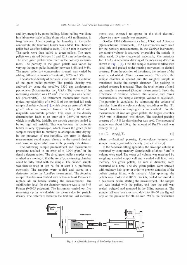
and dry strength by micro-balling. Micro-balling was done
in a laboratory-scale balling drum with a 0.8 m diameter, in
6-kg batches. After adjusting the humidity in the pellet
concentrate, the bentonite binder was added. The obtained
pellet feed was first balled to seeds, 3.5 to 5 mm in diameter.
The seeds were then balled to green pellets. The green
pellets were sieved between 10 and 12.5 mm before drying.
The dried green pellets were used in the porosity measure-
ment. The porosity in the green pellets was varied by
varying the green pellet humidity between 8.4% and 9.4%.
The green pellet dry compression strength was varied by
adding different amounts of bentonite, 0.2% to 1.5%.
The absolute density of particles is used in the calculation
of the green pellet porosity. The particle density was
analysed by using the AccuPyc 1330 gas displacement
pycnometer (Micromeritics Inc., USA). The volume of the
measuring chamber was 12 cm3. The inert gas was helium
6.0 (99.99990%). The instrument manufacturer states a
typical reproducibility of T 0.01% of the nominal full-scale
sample chamber volume [1], which gives an error of T 0.004g/cm3 when the sample chamber is fully filled with
magnetite concentrate powder. This error in the density
determination leads to an error of T 0.06% in porosity,
which is negligible. Initially, the particle densities tended to
be too high and instable. This was because the bentonite
binder is very hygroscopic, which makes the green pellet
samples susceptible to humidity re-absorption after drying.
In the presence of rest-humidity, the error in density
measurement could appear already in the second decimal
and cause an appreciable error in the porosity calculation.
The following sample pre-treatment and measurement
procedure resulted in an error of T 0.004 g/cm3 in the
density determination. The dried green pellet samples were
crushed in a mortar, so that the AccuPyc measuring chamber
could be fully filled with the sample. The crushed sample
was then re-dried at 105 -C for at least 4 h, preferably
overnight. The samples were cooled and stored in a
desiccator before the AccuPyc measurement. The AccuPyc
sample chamber was flushed with helium at least 15 times to
replace all air before starting the measurement. The
stabilization level for the chamber pressure was set to 3.45
Pa/min (0.0005 psig/min). The instrument carried out five
measuring cycles to calculate the mean value for particle
density. The difference between the first and last measure-
ments was expected to appear in the third decimal,
otherwise a new sample was prepared.
GeoPyc 1360 (Micromeritics Inc., USA) and Autoscan
(Quantachrome Instruments, USA) instruments were used
for the porosity measurements. In the GeoPyc instrument,
the sample volume is analyzed by packing the sample in
silica sand, DryFlo (registered trademark, Micromeritics
Inc., USA). A schematic drawing of the measuring device is
shown in Fig. 1 [2]. First, the sample chamber is filled with
sand only and packed under rotating movement to desired
pressure. From the position of the piston, the volume of the
sand is calculated (Blank measurement). Thereafter, the
sample chamber is opened and the weighed sample is
transferred inside the sample chamber. The packing to
desired pressure is repeated. Then, the total volume of sand
and sample is measured (Sample measurement). From the
difference in volume between the Sample and Blank
measurements, the sample envelope volume is calculated.
The porosity is calculated by subtracting the volume of
particles from the envelope volume according to Eq. (1).
Sample chambers of varying sizes are available. For the
measurement of iron ore green pellets, the largest chamber
(50.8 mm in diameter) was chosen. The standard packing
pressure of 145 N for this chamber was used. The amount of
sample was about 100 g, the amount of DryFlo sand was
exactly 30.0 g.
e ¼ Ve � m=qað Þ=Ve ð1Þwhere e =fractional porosity, Ve=envelope volume, m =
sample mass, qa=absolute density (particle density).
In the Autoscan filling apparatus, the envelope volume is
measured by using mercury. Sample cells of about 7 cm3 in
volume were used. The exact cell volume was measured by
weighing a sealed empty cell and a sealed cell filled with
mercury. Six green pellets, 10 mm in diameter, were
measured at a time. The dry green pellets were sprayed
with ordinary hair spray in order to prevent abrasion of the
pellets during filling with mercury. After spraying, the
pellets were re-dried at 105 -C for 4 h, cooled and stored in
a desiccator before starting the measurement. The sample
cell was loaded with the pellets, and then the cell was
sealed, weighed and mounted in the filling apparatus. The
sample cell was then evacuated down to 50–60 Am Hg and
kept at this pressure for 30–40 min. When the evacuation
Fig. 1. A schematic drawing of the GeoPyc instrument.
S.P.E. Forsmo, J.P. Vuori / Powder Technology 159 (2005) 71–7772

was completed, the cell was filled with mercury by slowly
increasing the pressure in the vacuum jar. The pressure was
increased to about 165 kPa in order to ensure proper filling.
The sample cell was then re-weighed and the envelope
volume was calculated. The porosity is calculated by
subtracting the volume of particles from the envelope
volume according to Eq. (1). By using the Washburn
equation [3] shown in Eq. (2), it could be estimated that in
the Autoscan filling apparatus, pores greater than about 9
Am in diameter were filled with mercury. According to
earlier knowledge, the pore openings in iron ore green
pellets are typically in the range of 1 to 2 Am. Therefore, the
mercury did not intrude inside the pores in the green pellets.
d ¼ � 4cpcosh ð2Þ
where p =applied pressure (MPa), d =pore diameter (Am),
c =surface tension of mercury (0.48 N m� 1), h =contactangle between mercury and pore wall (140.0-).
3. Results
3.1. Sample preparation: strengthening of the green pellets
During the GeoPyc measurement, the sample chamber is
rotated to help the sand to pack properly around the sample.
This mechanical movement causes abrasion of the green
pellets. The green pellet envelope volume decreases and the
detected porosity becomes too low. Also, due to the erosion,
magnetite concentrate particles get mixed in the DryFlo
sand. Therefore, to strengthen them, the green pellets were
sprayed with a fast drying lacquer (Servalack, Alcro,
Sweden). Both transparent and pigmented Servalack is
available. The Servalack lacquer with white pigment was
found practical, because the lacquer coverage on the green
pellets is visible. Three to five rounds with the lacquer
spray, while shaking the pellets slightly in between to
prevent them from fastening on the sample tray, was found
suitable. The manufacturer gives a drying time of 5 min.
However, the smell of the organic solvent takes all night to
dissipate. The sample pre-treatment had to be done in a
fume cupboard.
Ordinary hair spray and a marking spray (Mercalin RS
marking spray, Geveco Industri AB, Sweden) were tested
for strengthening the green pellets as well. The marking
spray formed excessively large droplets and the green
pellets tended to fasten on the bottom of the sample tray.
Ordinary hair spray did not increase the green pellet
strength enough, but the very finely divided spray proved
advantageous when treating green pellets balled with an
organic binder (Alcotac Fe13). In green pellets balled with
the organic binder, the Servalack lacquer penetrated inside
the pores and the green pellets remained black even after
several flushes with the white lacquer. When the lacquer
then started to dry, the green pellets tended to erode by
flaking from the outer surface. This was remedied by
spraying slightly with hair spray before the lacquer was
applied.
The porosity measured by the GeoPyc instrument on
untreated green pellets and on lacquer-strengthened green
pellets is shown in Fig. 2. The results show that there is a
distinct difference in the results; the lacquer-treated green
pellets showing systematically higher porosity values.
Drawing this difference against the dry compression
strength of the green pellets confirms that as the green
pellets become weaker, they erode to an increasing degree
during the GeoPyc measurement, see Fig. 3. This would
lead to erroneous conclusions when, for example, porosity
in green pellets with different binders and with different dry
strengths is studied. The Servalack lacquer treatment
prevents this systematic error and helps to keep the chamber
and the DryFlo sand cleaner.
3.2. Number of preparation cycles: consistent packing
In the GeoPyc instrument, the consolidation by a specific
force is repeated several times in order to get consistent
packing. The consolidation cycles, which are done before
the actual measurement is started, are called preparation
cycles. The consolidation cycles, which are used to calculate
the mean value for the envelope volume, are called
measuring cycles. A high number of consolidation cycles
increase the measuring time, but give a more reproducible
packing. The number of consolidation cycles needed for
iron ore green pellets was studied using lacquerized green
pellets. The increase in the envelope volume as a function of
the number of consolidation cycles is shown in Fig. 4. At
least 20 consolidation cycles are necessary before constant
envelope volume is reached. In the operator’s manual, five
preparation cycles is recommended as a good starting
number [2]. These results show that the number of
preparation cycles needed for iron ore green pellets is
appreciably higher. The number of preparation cycles was
Fig. 2. Porosity measured by the GeoPyc instrument on untreated and on
lacquer-strengthened iron ore green pellets. Conversion Factor=2.064.
S.P.E. Forsmo, J.P. Vuori / Powder Technology 159 (2005) 71–77 73
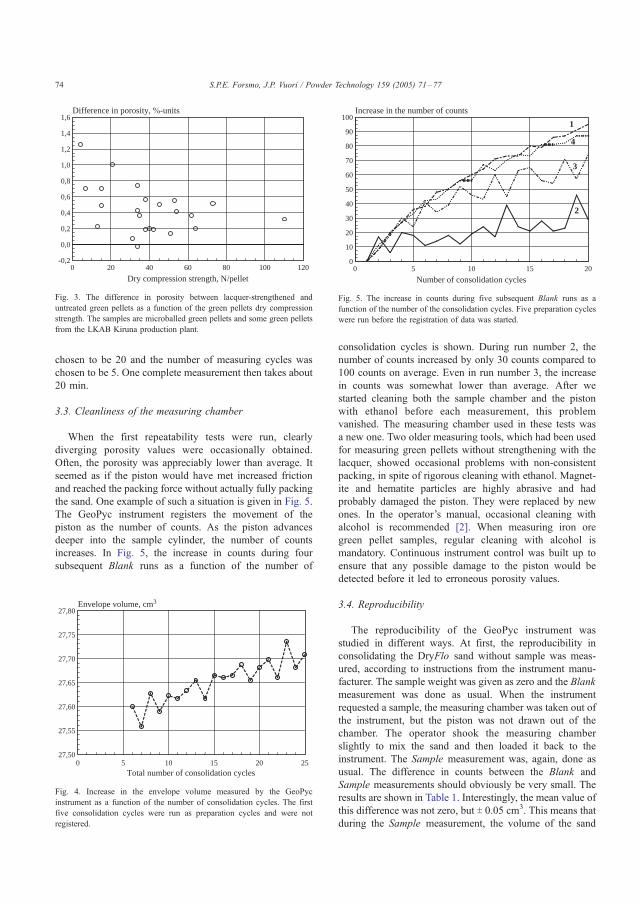
chosen to be 20 and the number of measuring cycles was
chosen to be 5. One complete measurement then takes about
20 min.
3.3. Cleanliness of the measuring chamber
When the first repeatability tests were run, clearly
diverging porosity values were occasionally obtained.
Often, the porosity was appreciably lower than average. It
seemed as if the piston would have met increased friction
and reached the packing force without actually fully packing
the sand. One example of such a situation is given in Fig. 5.
The GeoPyc instrument registers the movement of the
piston as the number of counts. As the piston advances
deeper into the sample cylinder, the number of counts
increases. In Fig. 5, the increase in counts during four
subsequent Blank runs as a function of the number of
consolidation cycles is shown. During run number 2, the
number of counts increased by only 30 counts compared to
100 counts on average. Even in run number 3, the increase
in counts was somewhat lower than average. After we
started cleaning both the sample chamber and the piston
with ethanol before each measurement, this problem
vanished. The measuring chamber used in these tests was
a new one. Two older measuring tools, which had been used
for measuring green pellets without strengthening with the
lacquer, showed occasional problems with non-consistent
packing, in spite of rigorous cleaning with ethanol. Magnet-
ite and hematite particles are highly abrasive and had
probably damaged the piston. They were replaced by new
ones. In the operator’s manual, occasional cleaning with
alcohol is recommended [2]. When measuring iron ore
green pellet samples, regular cleaning with alcohol is
mandatory. Continuous instrument control was built up to
ensure that any possible damage to the piston would be
detected before it led to erroneous porosity values.
3.4. Reproducibility
The reproducibility of the GeoPyc instrument was
studied in different ways. At first, the reproducibility in
consolidating the DryFlo sand without sample was meas-
ured, according to instructions from the instrument manu-
facturer. The sample weight was given as zero and the Blank
measurement was done as usual. When the instrument
requested a sample, the measuring chamber was taken out of
the instrument, but the piston was not drawn out of the
chamber. The operator shook the measuring chamber
slightly to mix the sand and then loaded it back to the
instrument. The Sample measurement was, again, done as
usual. The difference in counts between the Blank and
Sample measurements should obviously be very small. The
results are shown in Table 1. Interestingly, the mean value of
this difference was not zero, but T 0.05 cm3. This means that
during the Sample measurement, the volume of the sand
Total number of consolidation cycles
Envelope volume, cm3
0 5 10 15 20 2527,50
27,55
27,60
27,65
27,70
27,75
27,80
Fig. 4. Increase in the envelope volume measured by the GeoPyc
instrument as a function of the number of consolidation cycles. The first
five consolidation cycles were run as preparation cycles and were not
registered.
Number of consolidation cycles
Increase in the number of counts
0 5 10 15 200
10
20
30
40
50
60
70
80
90
1001
2
3
4
Fig. 5. The increase in counts during five subsequent Blank runs as a
function of the number of the consolidation cycles. Five preparation cycles
were run before the registration of data was started.
Dry compression strength, N/pellet
Difference in porosity, %-units
0 20 40 60 80 100 120-0,2
0,0
0,2
0,4
0,6
0,8
1,0
1,2
1,4
1,6
Fig. 3. The difference in porosity between lacquer-strengthened and
untreated green pellets as a function of the green pellets dry compression
strength. The samples are microballed green pellets and some green pellets
from the LKAB Kiruna production plant.
S.P.E. Forsmo, J.P. Vuori / Powder Technology 159 (2005) 71–7774
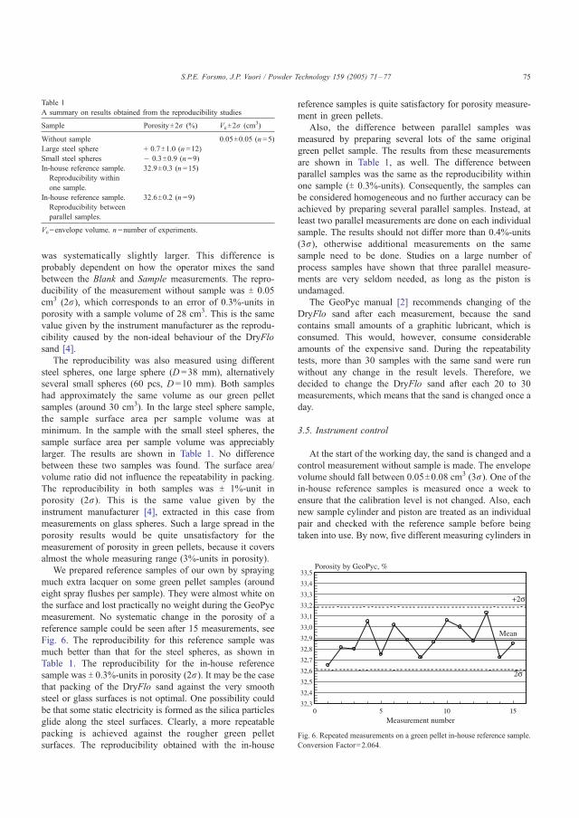
was systematically slightly larger. This difference is
probably dependent on how the operator mixes the sand
between the Blank and Sample measurements. The repro-
ducibility of the measurement without sample was T 0.05
cm3 (2r), which corresponds to an error of 0.3%-units in
porosity with a sample volume of 28 cm3. This is the same
value given by the instrument manufacturer as the reprodu-
cibility caused by the non-ideal behaviour of the DryFlo
sand [4].
The reproducibility was also measured using different
steel spheres, one large sphere (D =38 mm), alternatively
several small spheres (60 pcs, D =10 mm). Both samples
had approximately the same volume as our green pellet
samples (around 30 cm3). In the large steel sphere sample,
the sample surface area per sample volume was at
minimum. In the sample with the small steel spheres, the
sample surface area per sample volume was appreciably
larger. The results are shown in Table 1. No difference
between these two samples was found. The surface area/
volume ratio did not influence the repeatability in packing.
The reproducibility in both samples was T 1%-unit in
porosity (2r). This is the same value given by the
instrument manufacturer [4], extracted in this case from
measurements on glass spheres. Such a large spread in the
porosity results would be quite unsatisfactory for the
measurement of porosity in green pellets, because it covers
almost the whole measuring range (3%-units in porosity).
We prepared reference samples of our own by spraying
much extra lacquer on some green pellet samples (around
eight spray flushes per sample). They were almost white on
the surface and lost practically no weight during the GeoPyc
measurement. No systematic change in the porosity of a
reference sample could be seen after 15 measurements, see
Fig. 6. The reproducibility for this reference sample was
much better than that for the steel spheres, as shown in
Table 1. The reproducibility for the in-house reference
sample was T 0.3%-units in porosity (2r). It may be the case
that packing of the DryFlo sand against the very smooth
steel or glass surfaces is not optimal. One possibility could
be that some static electricity is formed as the silica particles
glide along the steel surfaces. Clearly, a more repeatable
packing is achieved against the rougher green pellet
surfaces. The reproducibility obtained with the in-house
reference samples is quite satisfactory for porosity measure-
ment in green pellets.
Also, the difference between parallel samples was
measured by preparing several lots of the same original
green pellet sample. The results from these measurements
are shown in Table 1, as well. The difference between
parallel samples was the same as the reproducibility within
one sample (T 0.3%-units). Consequently, the samples can
be considered homogeneous and no further accuracy can be
achieved by preparing several parallel samples. Instead, at
least two parallel measurements are done on each individual
sample. The results should not differ more than 0.4%-units
(3r), otherwise additional measurements on the same
sample need to be done. Studies on a large number of
process samples have shown that three parallel measure-
ments are very seldom needed, as long as the piston is
undamaged.
The GeoPyc manual [2] recommends changing of the
DryFlo sand after each measurement, because the sand
contains small amounts of a graphitic lubricant, which is
consumed. This would, however, consume considerable
amounts of the expensive sand. During the repeatability
tests, more than 30 samples with the same sand were run
without any change in the result levels. Therefore, we
decided to change the DryFlo sand after each 20 to 30
measurements, which means that the sand is changed once a
day.
3.5. Instrument control
At the start of the working day, the sand is changed and a
control measurement without sample is made. The envelope
volume should fall between 0.05T0.08 cm3 (3r). One of thein-house reference samples is measured once a week to
ensure that the calibration level is not changed. Also, each
new sample cylinder and piston are treated as an individual
pair and checked with the reference sample before being
taken into use. By now, five different measuring cylinders in
Table 1
A summary on results obtained from the reproducibility studies
Sample PorosityT2r (%) VeT2r (cm3)
Without sample 0.05T0.05 (n =5)
Large steel sphere + 0.7T1.0 (n =12)
Small steel spheres � 0.3T0.9 (n =9)
In-house reference sample.
Reproducibility within
one sample.
32.9T0.3 (n =15)
In-house reference sample.
Reproducibility between
parallel samples.
32.6T0.2 (n =9)
Ve=envelope volume. n =number of experiments.
Fig. 6. Repeated measurements on a green pellet in-house reference sample.
Conversion Factor=2.064.
S.P.E. Forsmo, J.P. Vuori / Powder Technology 159 (2005) 71–77 75
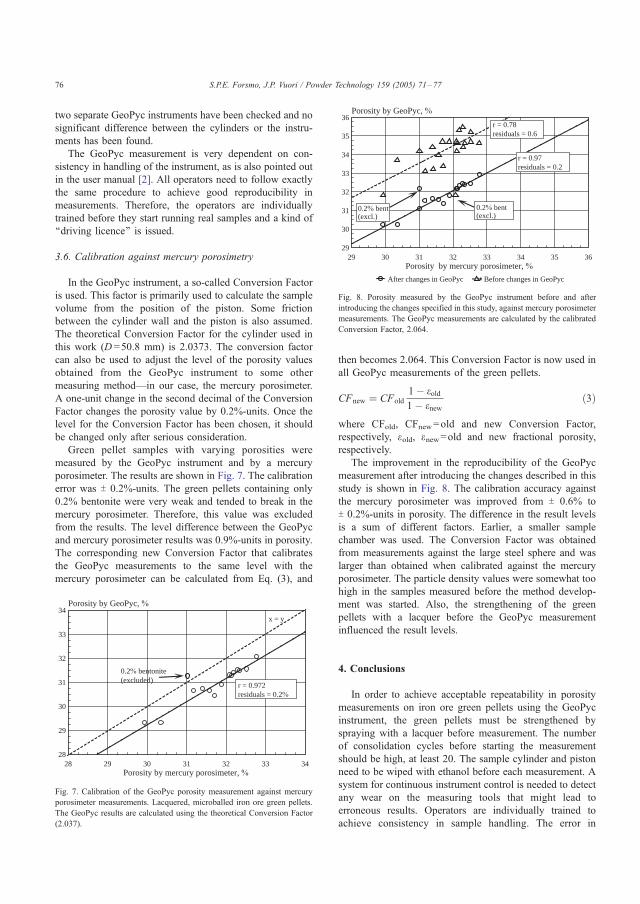
two separate GeoPyc instruments have been checked and no
significant difference between the cylinders or the instru-
ments has been found.
The GeoPyc measurement is very dependent on con-
sistency in handling of the instrument, as is also pointed out
in the user manual [2]. All operators need to follow exactly
the same procedure to achieve good reproducibility in
measurements. Therefore, the operators are individually
trained before they start running real samples and a kind of
‘‘driving licence’’ is issued.
3.6. Calibration against mercury porosimetry
In the GeoPyc instrument, a so-called Conversion Factor
is used. This factor is primarily used to calculate the sample
volume from the position of the piston. Some friction
between the cylinder wall and the piston is also assumed.
The theoretical Conversion Factor for the cylinder used in
this work (D =50.8 mm) is 2.0373. The conversion factor
can also be used to adjust the level of the porosity values
obtained from the GeoPyc instrument to some other
measuring method—in our case, the mercury porosimeter.
A one-unit change in the second decimal of the Conversion
Factor changes the porosity value by 0.2%-units. Once the
level for the Conversion Factor has been chosen, it should
be changed only after serious consideration.
Green pellet samples with varying porosities were
measured by the GeoPyc instrument and by a mercury
porosimeter. The results are shown in Fig. 7. The calibration
error was T 0.2%-units. The green pellets containing only
0.2% bentonite were very weak and tended to break in the
mercury porosimeter. Therefore, this value was excluded
from the results. The level difference between the GeoPyc
and mercury porosimeter results was 0.9%-units in porosity.
The corresponding new Conversion Factor that calibrates
the GeoPyc measurements to the same level with the
mercury porosimeter can be calculated from Eq. (3), and
then becomes 2.064. This Conversion Factor is now used in
all GeoPyc measurements of the green pellets.
CFnew ¼ CFold
1� eold1� enew
ð3Þ
where CFold, CFnew=old and new Conversion Factor,
respectively, eold, enew=old and new fractional porosity,
respectively.
The improvement in the reproducibility of the GeoPyc
measurement after introducing the changes described in this
study is shown in Fig. 8. The calibration accuracy against
the mercury porosimeter was improved from T 0.6% to
T 0.2%-units in porosity. The difference in the result levels
is a sum of different factors. Earlier, a smaller sample
chamber was used. The Conversion Factor was obtained
from measurements against the large steel sphere and was
larger than obtained when calibrated against the mercury
porosimeter. The particle density values were somewhat too
high in the samples measured before the method develop-
ment was started. Also, the strengthening of the green
pellets with a lacquer before the GeoPyc measurement
influenced the result levels.
4. Conclusions
In order to achieve acceptable repeatability in porosity
measurements on iron ore green pellets using the GeoPyc
instrument, the green pellets must be strengthened by
spraying with a lacquer before measurement. The number
of consolidation cycles before starting the measurement
should be high, at least 20. The sample cylinder and piston
need to be wiped with ethanol before each measurement. A
system for continuous instrument control is needed to detect
any wear on the measuring tools that might lead to
erroneous results. Operators are individually trained to
achieve consistency in sample handling. The error in
Porosity by mercury porosimeter, %
Porosity by GeoPyc, %
28 29 30 31 32 33 3428
29
30
31
32
33
34
r = 0.972residuals = 0.2%
0.2% bentonite(excluded)
x = y
Fig. 7. Calibration of the GeoPyc porosity measurement against mercury
porosimeter measurements. Lacquered, microballed iron ore green pellets.
The GeoPyc results are calculated using the theoretical Conversion Factor
(2.037).
Porosity by mercury porosimeter, %
Porosity by GeoPyc, %
29 30 31 32 33 34 35 3629
30
31
32
33
34
35
36
Before changes in GeoPycAfter changes in GeoPyc
0.2% bent(excl.)
r = 0.78residuals = 0.6
r = 0.97residuals = 0.2
0.2% bent(excl.)
Fig. 8. Porosity measured by the GeoPyc instrument before and after
introducing the changes specified in this study, against mercury porosimeter
measurements. The GeoPyc measurements are calculated by the calibrated
Conversion Factor, 2.064.
S.P.E. Forsmo, J.P. Vuori / Powder Technology 159 (2005) 71–7776
particle density determination should appear only in the
third decimal.
After introducing these changes, the GeoPyc instrument
has given highly satisfactory results on iron ore green
pellets. Calibration against mercury porosimetry showed an
error of 0.2%-units in porosity. The reproducibility of the
GeoPyc measurements was T 0.3%-units (2r) measured on
in-house reference samples. The GeoPyc instrument is easy
to use and the problematic handling of mercury is avoided.
In this work, the applicability of the GeoPyc measuring
method was studied exclusively with green pellets. How-
ever, the results are applicable for the measurement of
porosity in sintered and reduced pellets, as well. In that case,
it is not necessary to spray the pellets with a lacquer to
strengthen them, but it is necessary to prevent the abrasive
hematite dust from getting mixed with the DryFlo sand.
Acknowledgements
Funding from the Agricola Research Centre (ARC) at the
Lulea University of Technology and Luossavaara-Kiiruna-
vaara AB (LKAB) is gratefully acknowledged.
References
[1] Micromeritics Instrument Incorporation, AccuPyc 1330 Operator’s
Manual, 1996.
[2] Micromeritics Instrument Incorporation, GeoPyc 1360 Operator’s
Manual V3.01, 2001.
[3] T. Allen, Surface Area and Pore Size Determination, 5th ednRParticleSize Measurement, vol. 2, Chapman & Hall, London, 1997, 251 pp.
[4] Micromeritics Instrument Incorporation, Attaining envelope density
reproducibility and accuracy with your GeoPyc, Application Notes,
vol. 109, 1997.
S.P.E. Forsmo, J.P. Vuori / Powder Technology 159 (2005) 71–77 77

ARTICLE II
Oxidation of magnetite concentrate powders during storage and drying
S.P.E. Forsmo
International Journal of Mineral Processing 75 (2005) 135-144.
Reprinted with permission from Elsevier. Copyright 2005.
II

Oxidation of magnetite concentrate powders during storage
and drying
S.P.E. Forsmo*,1
LKAB, R&D, SE-98381 Malmberget, Sweden
Received 15 January 2004; received in revised form 24 June 2004; accepted 6 August 2004
Abstract
Oxidation of magnetite pellet concentrates (from LKAB, Sweden) during drying and storage was studied using
thermogravimetric analysis (TGA). The Fe2+content of a standard LKAB pellet feed decreased by 0.2% during heat treatment at
105 8C for 2 days. The results indicate that magnetite concentrates of pelletizing fineness already start to oxidize to g-hematite
during drying at 105 8C, although 105 8C is recommended by ISO 7764 and ISO 3087 and given as the maximum allowable
drying temperature in ISO 3082. The importance of drying time for the amount of magnetite oxidized should also be
recognized, but is not mentioned in the ISO standards. The sensitivity of magnetite particles for oxidation during drying could
not be predicted by measuring the BET surface area. A simple isothermal TGA run gives exact experimental data and is
recommended as a standard procedure before choosing the drying temperature for magnetite concentrate samples.
Oxidation during storage at room temperature was observed as well. The Fe2+content in a standard Luossavaara-
Kiirunavaara (LKAB) pellet feed decreased by 0.3% Fe2+during 4 years of storage at room temperature. Oxidation during
storage was completely hindered when the samples were stored in a freezer at �50 8C. Therefore, freezer storage is
recommended for all magnetite reference materials. These materials are used over several years and are especially susceptible to
oxidation because they are usually finely ground and high in Fe2+content. The results also show that if the magnetite sample has
partly oxidized to g-hematite, the oxidation curve obtained by TGA will overestimate the Fe2+content of the sample, if
background correction is necessary.
D 2004 Elsevier B.V. All rights reserved.
Keywords: magnetite; oxidation; thermogravimetric analysis; agglomeration; particle size
1. Introduction
The oxidation of magnetite mineral particles has
been widely studied because of its great importance in
the industrial production of iron ore pellets. The
oxidation reaction is highly exothermic and actually
provides more than two-thirds of the total sintering
0301-7516/$ - see front matter D 2004 Elsevier B.V. All rights reserved.
doi:10.1016/j.minpro.2004.08.010
* Fax: +46 970 30617.
E-mail address: [email protected] Part of a doctoral thesis project, Lule3 University of
Technology, Division of Process Metallurgy.
Int. J. Miner. Process. 75 (2005) 135–144
www.elsevier.com/locate/ijminpro
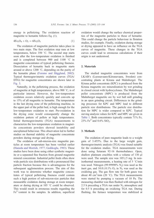
energy in pelletizing. The oxidation reaction of
magnetite to hematite follows Eq. (1).
4Fe3O4 þ O2 ¼ 6Fe2O3 ð1ÞThe oxidation of magnetite particles takes place in
two main steps. The first oxidation step runs at low
temperatures, below 350 8C. The second step starts
soon after the low-temperature oxidation is finished
and is completed between 900 and 1100 8C in
magnetite concentrates of typical pelletizing fineness.
Dissociation of hematite back to magnetite starts
around or above 1200 8C, depending on the purity of
the hematite phase (Forsmo and Hagglund, 2002).
Typical thermogravimetric oxidation curves (TGA/
DTG) for magnetite concentrates are shown later in
Fig. 3.
Naturally, in the pelletizing process, the oxidation
of magnetite at high temperatures, above 900 8C, is ofparticular interest. However, the low-temperature
oxidation occurs relatively quickly and converts up
to 15% of all magnetite to hematite. The temperature
in the last drying zone of the pelletizing machine, in
the upper part of the pellet bed, is high enough for the
low-temperature oxidation to start. Pre-oxidation in
the drying zone would consequently change the
oxidation pattern of pellets at high temperatures.
Initial thermogravimetric (TGA) measurements to
characterize the low-temperature oxidation in magnet-
ite concentrate powders showed instability and
unexplained behaviour. This observation led to further
studies on thermal stability of magnetite concentrate
powders during storage and drying.
The oxidation of sub-micron-size magnetite par-
ticles at room temperature has been verified earlier
(Haneda and Morrish, 1977; Gedikoglu, 1983). These
studies have been done using either synthetic magnet-
ite or a separated fine fraction from ground magnetite
mineral concentrate. Industrial pellet feeds often show
wide particle size distributions with a pronounced fine
particle fraction because this is advantageous for the
subsequent agglomeration process. The aim of this
work was to determine whether magnetite concen-
trates of typical pelletizing fineness could contain
such a high portion of sub-micron-size particles that
measurable oxidation during storage at room temper-
ature or during drying at 105 8C could be observed.
This would result in erroneous results regarding the
Fe2+content in the samples. In addition, superficial
oxidation would change the surface chemical proper-
ties of the magnetite particles to those of hematite.
This could change the particle behaviour in flotation
studies, for example. Finally, oxidation during storage
or drying appeared to have an influence on the TGA
curves of magnetite. These changes in the TGA
curves could lead to erroneous calculations if their
origin is not understood.
2. Materials
The studied magnetite concentrates were from
LKAB’s (Luossavaara-Kiirunavaara, Sweden) con-
centrating plants at Kiruna and Malmberget. The
Kiruna pellet concentrate (KPC) is produced from the
Kiruna magnetite ore mineralization by wet grinding
in closed circuit with hydrocyclones. The Malmberget
pellet concentrate (MPC) is produced from the
Malmberget magnetite ore by wet ball mill grinding
in an open grinding circuit. Differences in the grind-
ing processes for KPC and MPC lead to different
particle size distributions. The particle size distribu-
tion for MPC is wider compared to KPC. Typical
sieving analysis values for KPC and MPC are given in
Table 1. Both concentrates typically contain 71% Fe,
23% Fe2+and 0.6% SiO2.
3. Methods
The oxidation of pure magnetite leads to a weight
gain of 3.455%. Due to the large weight gain,
thermogravimetric analysis (TGA) was found suitable
for the oxidation studies. TGA measurements were
done using Setaram 92-16 thermobalance. Open,
shallow platinum crucibles with a volume of 130 Alwere used. The sample size was 105F5 mg. In non-
isothermal measurements, a heating rate of 5 8C/min
was used. Nitrogen (99.99990% N2) was used as the
inert gas, and 10.0F0.1% O2 in N2 was used as the
oxidizing gas. The gas flow rate for both gases was
about 40 cm3/min (20 8C). The TGA measurements
were started by pumping a vacuum of 10 Pa. The
measuring chamber was then flushed with nitrogen for
2.5 h preceding a TGA run under N2 atmosphere and
for 0.5 h preceding an oxidizing TGA run. During
flushing, the furnace temperature was stabilized at
S.P.E. Forsmo / Int. J. Miner. Process. 75 (2005) 135–144136
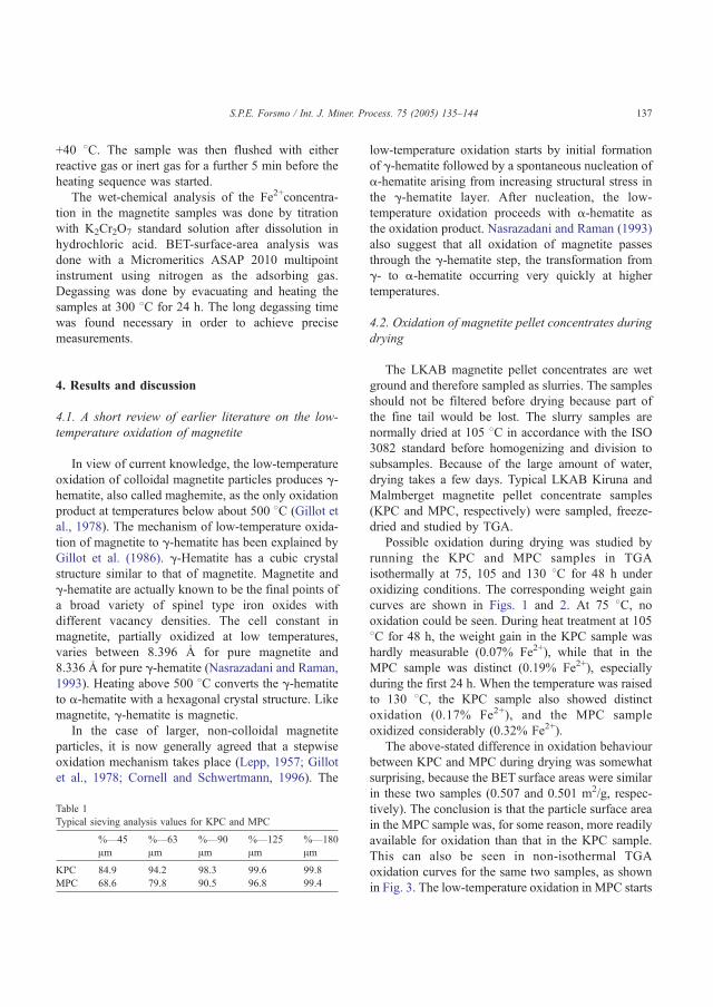
+40 8C. The sample was then flushed with either
reactive gas or inert gas for a further 5 min before the
heating sequence was started.
The wet-chemical analysis of the Fe2+concentra-
tion in the magnetite samples was done by titration
with K2Cr2O7 standard solution after dissolution in
hydrochloric acid. BET-surface-area analysis was
done with a Micromeritics ASAP 2010 multipoint
instrument using nitrogen as the adsorbing gas.
Degassing was done by evacuating and heating the
samples at 300 8C for 24 h. The long degassing time
was found necessary in order to achieve precise
measurements.
4. Results and discussion
4.1. A short review of earlier literature on the low-
temperature oxidation of magnetite
In view of current knowledge, the low-temperature
oxidation of colloidal magnetite particles produces g-hematite, also called maghemite, as the only oxidation
product at temperatures below about 500 8C (Gillot et
al., 1978). The mechanism of low-temperature oxida-
tion of magnetite to g-hematite has been explained by
Gillot et al. (1986). g-Hematite has a cubic crystal
structure similar to that of magnetite. Magnetite and
g-hematite are actually known to be the final points of
a broad variety of spinel type iron oxides with
different vacancy densities. The cell constant in
magnetite, partially oxidized at low temperatures,
varies between 8.396 2 for pure magnetite and
8.336 2 for pure g-hematite (Nasrazadani and Raman,
1993). Heating above 500 8C converts the g-hematite
to a-hematite with a hexagonal crystal structure. Like
magnetite, g-hematite is magnetic.
In the case of larger, non-colloidal magnetite
particles, it is now generally agreed that a stepwise
oxidation mechanism takes place (Lepp, 1957; Gillot
et al., 1978; Cornell and Schwertmann, 1996). The
low-temperature oxidation starts by initial formation
of g-hematite followed by a spontaneous nucleation of
a-hematite arising from increasing structural stress in
the g-hematite layer. After nucleation, the low-
temperature oxidation proceeds with a-hematite as
the oxidation product. Nasrazadani and Raman (1993)
also suggest that all oxidation of magnetite passes
through the g-hematite step, the transformation from
g- to a-hematite occurring very quickly at higher
temperatures.
4.2. Oxidation of magnetite pellet concentrates during
drying
The LKAB magnetite pellet concentrates are wet
ground and therefore sampled as slurries. The samples
should not be filtered before drying because part of
the fine tail would be lost. The slurry samples are
normally dried at 105 8C in accordance with the ISO
3082 standard before homogenizing and division to
subsamples. Because of the large amount of water,
drying takes a few days. Typical LKAB Kiruna and
Malmberget magnetite pellet concentrate samples
(KPC and MPC, respectively) were sampled, freeze-
dried and studied by TGA.
Possible oxidation during drying was studied by
running the KPC and MPC samples in TGA
isothermally at 75, 105 and 130 8C for 48 h under
oxidizing conditions. The corresponding weight gain
curves are shown in Figs. 1 and 2. At 75 8C, no
oxidation could be seen. During heat treatment at 105
8C for 48 h, the weight gain in the KPC sample was
hardly measurable (0.07% Fe2+), while that in the
MPC sample was distinct (0.19% Fe2+), especially
during the first 24 h. When the temperature was raised
to 130 8C, the KPC sample also showed distinct
oxidation (0.17% Fe2+), and the MPC sample
oxidized considerably (0.32% Fe2+).
The above-stated difference in oxidation behaviour
between KPC and MPC during drying was somewhat
surprising, because the BET surface areas were similar
in these two samples (0.507 and 0.501 m2/g, respec-
tively). The conclusion is that the particle surface area
in the MPC sample was, for some reason, more readily
available for oxidation than that in the KPC sample.
This can also be seen in non-isothermal TGA
oxidation curves for the same two samples, as shown
in Fig. 3. The low-temperature oxidation in MPC starts
Table 1
Typical sieving analysis values for KPC and MPC
%—45
Am%—63
Am%—90
Am%—125
Am%—180
Am
KPC 84.9 94.2 98.3 99.6 99.8
MPC 68.6 79.8 90.5 96.8 99.4
S.P.E. Forsmo / Int. J. Miner. Process. 75 (2005) 135–144 137
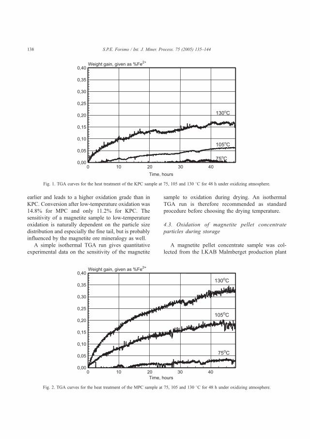
earlier and leads to a higher oxidation grade than in
KPC. Conversion after low-temperature oxidation was
14.8% for MPC and only 11.2% for KPC. The
sensitivity of a magnetite sample to low-temperature
oxidation is naturally dependent on the particle size
distribution and especially the fine tail, but is probably
influenced by the magnetite ore mineralogy as well.
A simple isothermal TGA run gives quantitative
experimental data on the sensitivity of the magnetite
sample to oxidation during drying. An isothermal
TGA run is therefore recommended as standard
procedure before choosing the drying temperature.
4.3. Oxidation of magnetite pellet concentrate
particles during storage
A magnetite pellet concentrate sample was col-
lected from the LKAB Malmberget production plant
Fig. 2. TGA curves for the heat treatment of the MPC sample at 75, 105 and 130 8C for 48 h under oxidizing atmosphere.
Fig. 1. TGA curves for the heat treatment of the KPC sample at 75, 105 and 130 8C for 48 h under oxidizing atmosphere.
S.P.E. Forsmo / Int. J. Miner. Process. 75 (2005) 135–144138

(MPC). The sample was filtered in a Buchner funnel,
and the filter cake was divided into two parallel
samples. One part of the sample was allowed to dry at
room temperature and then stored in a paper sample
bag at room temperature. The other part was freeze-
dried and stored in a freezer at �50 8C. These two
samples were chemically analyzed directly after
sample preparation and showed 23.7% Fe2+. They
were also analyzed after 4 years of storage. The
sample stored in the freezer at �50 8C still showed
23.7% Fe2+, while the other sample stored at room
temperature showed only 23.4% Fe2+. The results
show that magnetite concentrate samples of pelletiz-
ing fineness are susceptible to oxidation during
storage at room temperature. The oxidation was
completely hindered when the samples were stored
in a freezer.
4.4. Influence of the low-temperature oxidation of
magnetite on the TGA curves
The same two MPC samples specified in the
previous chapter were also measured by TGA, first
directly after sample preparation and then more or less
regularly during the 4 years of storage. Observations
regarding changes in the TGA curves are reported
below.
4.4.1. Change in weight gain over the low-temper-
ature oxidation peak
The weight gain (dmL) over the low-temperature
oxidation peak as a function of varying storage time is
shown in Fig. 4. The sample stored at room temper-
ature showed gradually decreasing weight gain. After
4 years of storage, the dmL had decreased by 0.3%
Fe2+, which is the same difference as obtained from
the chemically analyzed Fe2+values. The dmL for the
Fig. 4. Low-temperature oxidation integral (dmL) as a function of
storage time for two parallel MPC samples. One was stored at room
temperature, the other in a freezer at �50 8C.
Fig. 3. Non-isothermal TG/DTG oxidation curves for KPC (solid lines) and MPC (dashed lines).
S.P.E. Forsmo / Int. J. Miner. Process. 75 (2005) 135–144 139
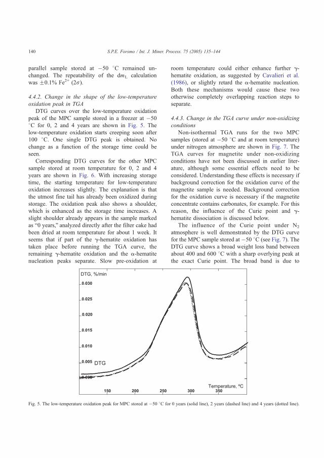
parallel sample stored at �50 8C remained un-
changed. The repeatability of the dmL calculation
was F0.1% Fe2+ (2r).
4.4.2. Change in the shape of the low-temperature
oxidation peak in TGA
DTG curves over the low-temperature oxidation
peak of the MPC sample stored in a freezer at �50
8C for 0, 2 and 4 years are shown in Fig. 5. The
low-temperature oxidation starts creeping soon after
100 8C. One single DTG peak is obtained. No
change as a function of the storage time could be
seen.
Corresponding DTG curves for the other MPC
sample stored at room temperature for 0, 2 and 4
years are shown in Fig. 6. With increasing storage
time, the starting temperature for low-temperature
oxidation increases slightly. The explanation is that
the utmost fine tail has already been oxidized during
storage. The oxidation peak also shows a shoulder,
which is enhanced as the storage time increases. A
slight shoulder already appears in the sample marked
as b0 years,Q analyzed directly after the filter cake had
been dried at room temperature for about 1 week. It
seems that if part of the g-hematite oxidation has
taken place before running the TGA curve, the
remaining g-hematite oxidation and the a-hematite
nucleation peaks separate. Slow pre-oxidation at
room temperature could either enhance further g-hematite oxidation, as suggested by Cavalieri et al.
(1986), or slightly retard the a-hematite nucleation.
Both these mechanisms would cause these two
otherwise completely overlapping reaction steps to
separate.
4.4.3. Change in the TGA curve under non-oxidizing
conditions
Non-isothermal TGA runs for the two MPC
samples (stored at �50 8C and at room temperature)
under nitrogen atmosphere are shown in Fig. 7. The
TGA curves for magnetite under non-oxidizing
conditions have not been discussed in earlier liter-
ature, although some essential effects need to be
considered. Understanding these effects is necessary if
background correction for the oxidation curve of the
magnetite sample is needed. Background correction
for the oxidation curve is necessary if the magnetite
concentrate contains carbonates, for example. For this
reason, the influence of the Curie point and g-hematite dissociation is discussed below.
The influence of the Curie point under N2
atmosphere is well demonstrated by the DTG curve
for the MPC sample stored at�50 8C (see Fig. 7). The
DTG curve shows a broad weight loss band between
about 400 and 600 8C with a sharp overlying peak at
the exact Curie point. The broad band is due to
Fig. 5. The low-temperature oxidation peak for MPC stored at �50 8C for 0 years (solid line), 2 years (dashed line) and 4 years (dotted line).
S.P.E. Forsmo / Int. J. Miner. Process. 75 (2005) 135–144140
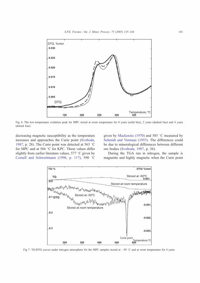
decreasing magnetic susceptibility as the temperature
increases and approaches the Curie point (Svoboda,
1987, p. 28). The Curie point was detected at 563 8Cfor MPC and at 566 8C for KPC. These values differ
slightly from earlier literature values, 577 8C given by
Cornell and Schwertmann (1996, p. 117), 590 8C
given by Mackenzie (1970) and 585 8C measured by
Schmidt and Vermaas (1955). The differences could
be due to mineralogical differences between different
ore bodies (Svoboda, 1987, p. 36).
During the TGA run in nitrogen, the sample is
magnetite and highly magnetic when the Curie point
Fig 7. TG/DTG curves under nitrogen atmosphere for the MPC samples stored at �50 8C and at room temperature for 4 years.
Fig. 6. The low-temperature oxidation peak for MPC stored at room temperature for 0 years (solid line), 2 years (dashed line) and 4 years
(dotted line).
S.P.E. Forsmo / Int. J. Miner. Process. 75 (2005) 135–144 141
is reached. The weight change at the Curie point
becomes therefore appreciable. However, when the
sample is run under oxidizing atmosphere, almost half
of the sample has already oxidized to hematite when
the Curie point is reached. For this reason, the weight
change at the Curie point under oxidizing atmosphere
is much smaller, often hardly visible. Applying
background correction on the oxidation TGA curve
of magnetite samples leads, therefore, to a slight
overestimation of the Fe2+content. Under the running
conditions used in this work, the weight loss under
non-oxidizing atmosphere caused by the Curie point
was calculated to be 0.035 dm-% (0.24% Fe2+) and
should be subtracted from the total oxidation weight
gain calculated from the background corrected oxida-
tion run.
The DTG curve for the MPC sample stored at room
temperature showed an additional broad weight loss
band between 200 8C and the Curie point. According
to Wells (1984, p. 552), g-hematite dissociates back to
magnetite at 250 8C in vacuo. It is reasonable to
expect that this dissociation takes place even under
nitrogen atmosphere with extremely low oxygen
content. These conditions are met during the back-
ground run in TGA (99.99990% N2). The broadness
of the dissociation band reveals that the reaction rate
is quite slow. A weight loss in the background run
results in a corresponding weight gain in the oxidation
run if background correction is applied. Therefore, the
final weight gain from the TGA oxidation run will be
overestimated. If the sample has oxidized all the way
to a-hematite, the dissociation only starts at about
1200 8C and does not influence the oxidation weight
gain.
Interestingly, the final weight gain after back-
ground correction of the TGA oxidation curves
actually describes the Fe2+content of the original
sample, before the low-temperature oxidation started.
This way, the amount of magnetite oxidized at room
temperature during storage can be estimated from the
difference between the background-corrected and
uncorrected thermograms. These calculations were
tested on several LKAB magnetite samples with
different fineness, and the results showed a surpris-
ingly good fit with the chemically analyzed Fe2+val-
ues. As it is of interest for the analyst to know, if, for
example, a certain magnetite concentrate reference
sample has oxidized during storage (and, therefore,
the Fe2+content has decreased), an example of these
calculations is shown below. The precision could,
however, be influenced by the mineralogical proper-
ties of the iron ore.
The original Fe2+content in the MPC sample was
23.7% and was unchanged after 4 years in the freezer.
TGA gave 23.8% Fe2+, the same value without
background correction and after background correc-
tion combined with the Curie point correction.
Because no oxidation during storage took place and
the sample does not contain carbonates, both calcu-
lation methods give the same result. For the MPC
sample stored at room temperature, TGA without
background correction showed 23.3% Fe2+, which fits
well with the chemically analyzed value 23.4%
Fe2+and describes the Fe2+content in the sample at
the moment the analysis was run. Using background
correction and correction for the Curie point in TGA,
the same sample gave the original Fe2+content,
23.7%. This describes the Fe2+content in the sample
before low-temperature oxidation started. The differ-
ence (0.3% Fe2+) describes the amount of magnetite
oxidized during storage.
5. Conclusions
Possible oxidation of magnetite concentrate par-
ticles during sample preparation or storage leads to
decreasing Fe2+analysis results. This is problematic in
many ways; one example is instability of both
international and in-house magnetite standard materi-
als, used to control the result level in wet-chemical
analysis of Fe2+. In addition, the surface properties of
the magnetite particles change due to oxidation and
become those of g-hematite. This could change the
sample behaviour during small-scale agglomeration or
flotation tests. Partial oxidation could also lead to
bindings in contact points between the magnetite
particles and cause dispersion problems during
particle size measurement. In general, any changes
in the sample due to sample pretreatment or during
storage can be disruptive and cause unexpected
sample behaviour.
The results point out that special care should be
taken during drying of magnetite pellet concentrate
slurries to avoid erroneous Fe2+results. In a normal
LKAB pellet feed, the Fe2+content decreased by
S.P.E. Forsmo / Int. J. Miner. Process. 75 (2005) 135–144142
0.2% during heat treatment at 105 8C for 2 days.
Therefore, drying of finely ground magnetite slurries
at 105 8C is questionable, although 105 8C is
recommended by ISO 7764 (1985) and ISO 3087
(1987) and given as the maximum allowable drying
temperature in ISO 3082 (2000). The importance of
drying time should also be recognized. The samples
should be removed from the drying furnace as soon
as they are dry and not left there, for example, over
weekends.
The sensitivity of magnetite particles to low-
temperature oxidation cannot be predicted by measur-
ing the BET surface area. A prolonged isothermal
TGA run is recommended as standard procedure
before choosing the drying temperature for a specific
type of magnetite concentrate sample. Once the drying
temperature has been selected using the TGA curves
as a guideline, it can be applied to all similar samples
thereafter. For very sensitive samples, the choice is
either to decrease the drying temperature to around 75
8C and accept the inconvenience of a much longer
drying time or to use freeze-drying, which is tedious
because of the large amounts of water in slurry
samples.
Oxidation during storage at room temperature was
detected as well. The Fe2+content in a normal LKAB
pellet feed decreased by 0.3%Fe2+during 4 years of
storage at room temperature. Oxidation during storage
was completely hindered when the samples were
stored in a freezer at �50 8C. Several samples were
studied, although only a few are reported here. Even a
very finely ground KPC sample with a BET surface
area of 1.15 m2/g remained unchanged during storage
at �50 8C. Therefore, for prolonged storage of
magnetite concentrate samples (for example, reference
materials), the use of a freezer is recommended—
especially if the surface chemical or oxidation proper-
ties of the sample are of interest. For larger samples, a
good alternative in our climate in Swedish Lapland is
to store the samples outdoors. The long winter period
provides a natural freezer, and the short summer is
only moderately warm. In addition, magnetite con-
centrate samples should not be allowed to stand in
direct daylight or near analysis instruments that
radiate heat.
When the oxidation of magnetite samples during
drying and storage is understood, an explanation for
certain behaviour in TGA thermograms is also
gained. Oxidation during storage did split the low-
temperature oxidation peak to two fairly well-sepa-
rated peaks. The first one can be explained by the
oxidation of magnetite to g-hematite, the second by
conversion of g-hematite to a-hematite. TGA thermo-
grams under non-oxidizing conditions showed that
any g-hematite formed during storage or drying will
dissociate back to magnetite. This results in a weight
loss specific only for the oxygen-free TGA measure-
ment. Therefore, if background correction for the
oxidation of magnetite samples is needed (for
example, due to calcining), any g-hematite in the
sample would lead to an overestimation of the
Fe2+content.
Acknowledgements
Funding from the Agricola Research Centre (ARC)
at the Lule3 University of Technology and LKAB is
gratefully acknowledged.
References
Cavalieri, A.L., Aglietti, E.F., Scian, A.N., Porto Lopez, J.M., 1986.
Mechanochemical alterations in magnetite crystals. React.
Solids 2, 215–222.
Cornell, R.M., Schwertmann, U., 1996. The iron oxides. Structure,
properties, reactions, occurrence and uses. VCH Verlagsgesell-
schaft, Weinheim, FRG.
Forsmo, S.P.E., H7gglund, A., 2002. Influence of the olivine
additive fineness on the oxidation of magnetite pellets. Int. J.
Miner. Process. 70, 109–122.
Gedikoglu, A., 1983. Mfssbauer study of low-temperature oxida-
tion in natural magnetite. Scr. Metall. 17, 45–48.
Gillot, B., Rousset, A.F., Dupre, G., 1978. Influence of crystallite
size on the oxidation kinetics of magnetite. J. Solid State Chem.
25, 263–271.
Gillot, B., Jemmali, F., Rousset, A., 1986. Kinetics and mechanism
of ferrous spinel oxidation studied by electrical conductivity and
thermogravimetry. J. Mater. Sci. 21, 4436–4442.
Haneda, K., Morrish, A.H., 1977. Magnetite to maghemite trans-
formation in ultrafine particles. J. Phys. 38 (C1), 321–323.
International Standard ISO 3087, 1987. Iron ores—Determination
of moisture content of a consignment.
International Standard ISO 3082, 2000. Iron ores—Sampling and
sample preparation procedures.
International Standard ISO 7764, 1985. Iron ores—Preparation of
pre-dried test samples for chemical analysis.
Lepp, H., 1957. Stages in the oxidation of magnetite. Am. Mineral.
42, 679–681.
S.P.E. Forsmo / Int. J. Miner. Process. 75 (2005) 135–144 143

Mackenzie, R.C. (Ed.), 1970. Differential Thermal Analysis.
Academic Press, London, pp. 272–277.
Nasrazadani, S., Raman, A., 1993. The application of infrared
spectroscopy to the study of rust systems—II. Study of cation
deficiency in magnetite (Fe3O4) produced during its trans-
formation to maghemite (g-Fe2O3) and hematite (a-Fe2O3).
Corros. Sci. 34 (8), 1355–1365.
Schmidt, E.R., Vermaas, F.H.S., 1955. Differential thermal analysis
and cell dimensions of some natural magnetites. Am. Mineral.
40, 422–431.
Svoboda, J., 1987. Magnetic Methods for the Treatment of
Minerals. Elsevier, Amsterdam.
Wells, A.F., 1984. Structural Inorganic Chemistry, 5th ed. Clar-
endon Press, Oxford, pp. 552.
S.P.E. Forsmo / Int. J. Miner. Process. 75 (2005) 135–144144
ARTICLE III
Binding mechanisms in wet iron ore green pellets with a bentonite binder
S.P.E. Forsmo, A.J. Apelqvist, B.M.T. Björkman, P-O. Samskog
Powder Technology 169 (2006) 147-158.
Reprinted with permission from Elsevier. Copyright 2006.
III

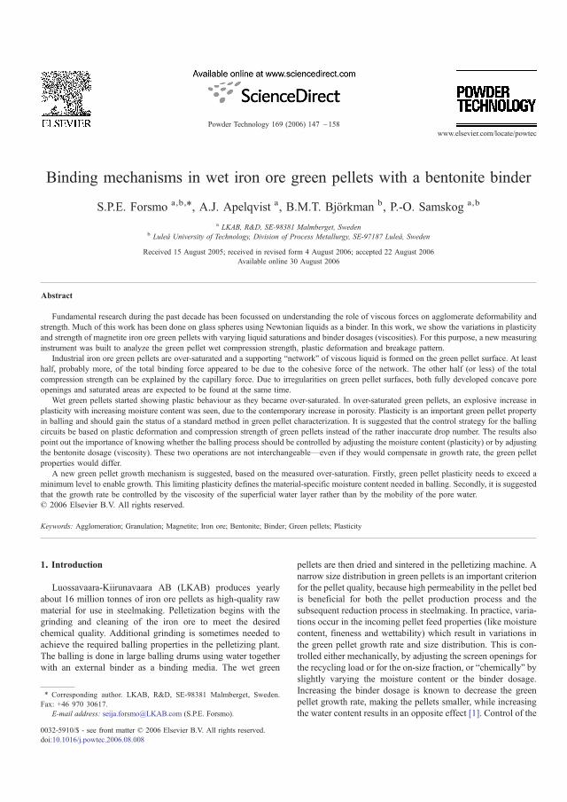
Binding mechanisms in wet iron ore green pellets with a bentonite binder
S.P.E. Forsmo a,b,⁎, A.J. Apelqvist a, B.M.T. Björkman b, P.-O. Samskog a,b
a LKAB, R&D, SE-98381 Malmberget, Swedenb Luleå University of Technology, Division of Process Metallurgy, SE-97187 Luleå, Sweden
Received 15 August 2005; received in revised form 4 August 2006; accepted 22 August 2006Available online 30 August 2006
Abstract
Fundamental research during the past decade has been focussed on understanding the role of viscous forces on agglomerate deformability andstrength. Much of this work has been done on glass spheres using Newtonian liquids as a binder. In this work, we show the variations in plasticityand strength of magnetite iron ore green pellets with varying liquid saturations and binder dosages (viscosities). For this purpose, a new measuringinstrument was built to analyze the green pellet wet compression strength, plastic deformation and breakage pattern.
Industrial iron ore green pellets are over-saturated and a supporting “network” of viscous liquid is formed on the green pellet surface. At leasthalf, probably more, of the total binding force appeared to be due to the cohesive force of the network. The other half (or less) of the totalcompression strength can be explained by the capillary force. Due to irregularities on green pellet surfaces, both fully developed concave poreopenings and saturated areas are expected to be found at the same time.
Wet green pellets started showing plastic behaviour as they became over-saturated. In over-saturated green pellets, an explosive increase inplasticity with increasing moisture content was seen, due to the contemporary increase in porosity. Plasticity is an important green pellet propertyin balling and should gain the status of a standard method in green pellet characterization. It is suggested that the control strategy for the ballingcircuits be based on plastic deformation and compression strength of green pellets instead of the rather inaccurate drop number. The results alsopoint out the importance of knowing whether the balling process should be controlled by adjusting the moisture content (plasticity) or by adjustingthe bentonite dosage (viscosity). These two operations are not interchangeable—even if they would compensate in growth rate, the green pelletproperties would differ.
A new green pellet growth mechanism is suggested, based on the measured over-saturation. Firstly, green pellet plasticity needs to exceed aminimum level to enable growth. This limiting plasticity defines the material-specific moisture content needed in balling. Secondly, it is suggestedthat the growth rate be controlled by the viscosity of the superficial water layer rather than by the mobility of the pore water.© 2006 Elsevier B.V. All rights reserved.
Keywords: Agglomeration; Granulation; Magnetite; Iron ore; Bentonite; Binder; Green pellets; Plasticity
1. Introduction
Luossavaara-Kiirunavaara AB (LKAB) produces yearlyabout 16 million tonnes of iron ore pellets as high-quality rawmaterial for use in steelmaking. Pelletization begins with thegrinding and cleaning of the iron ore to meet the desiredchemical quality. Additional grinding is sometimes needed toachieve the required balling properties in the pelletizing plant.The balling is done in large balling drums using water togetherwith an external binder as a binding media. The wet green
pellets are then dried and sintered in the pelletizing machine. Anarrow size distribution in green pellets is an important criterionfor the pellet quality, because high permeability in the pellet bedis beneficial for both the pellet production process and thesubsequent reduction process in steelmaking. In practice, varia-tions occur in the incoming pellet feed properties (like moisturecontent, fineness and wettability) which result in variations inthe green pellet growth rate and size distribution. This is con-trolled either mechanically, by adjusting the screen openings forthe recycling load or for the on-size fraction, or “chemically” byslightly varying the moisture content or the binder dosage.Increasing the binder dosage is known to decrease the greenpellet growth rate, making the pellets smaller, while increasingthe water content results in an opposite effect [1]. Control of the
Powder Technology 169 (2006) 147 –158www.elsevier.com/locate/powtec
⁎ Corresponding author. LKAB, R&D, SE-98381 Malmberget, Sweden.Fax: +46 970 30617.
E-mail address: [email protected] (S.P.E. Forsmo).
0032-5910/$ - see front matter © 2006 Elsevier B.V. All rights reserved.doi:10.1016/j.powtec.2006.08.008

balling circuits is largely based on the practical knowledge ofexperienced operators. This lack of a well-defined controlstrategy is largely due to insufficient understanding of thebinding mechanisms and inadequate measuring methods tocontrol the green pellet quality.
The capillary theory for wet agglomerate strength is wellestablished [2–4] and described in agglomeration textbooks [5–8]. It applies to particle systems with a freely movable binder,like water. The green pellet wet strength reaches a maximumwhen the pores are completely filled with water and concavesurfaces are formed in the pore openings due to the capillaryforces. This takes place at around 90–95% liquid saturation, asschematically shown in Fig. 1. The wet agglomerate strength atthe point of maximum (in the capillary state) is given by Eq. (1)[4]. Liquid saturation (S) describes the portion of the porevolume which is filled with the binder liquid and is calculatedfrom Eq. (2). According to the capillary theory, at S=100%,flooding takes place—the agglomerate deforms under its ownweight. As the agglomerate is slowly dried, the main bindingforce is the capillary force as long as part of the capillaries arestill filled with water, approximately down to S=30%.Thereafter, binding by liquid bridges controls the strength.The agglomerate strength with fully developed liquid bridges(S=30%) is only about 35% of the maximum strength.
rc ¼ ad1−ee
d gd1dd cosh ð1Þ
S ¼ 100F100−F
d1−ee
dqpqL
ð2Þ
where σc=green pellet wet tensile strength due to the capillaryforces; a=constant; ε=fractional porosity; γ=surface tension;d=average particle size; θ=contact angle; S=liquid saturation;F=moisture content by wet weight; ρp, ρL=density for particlesand water, respectively.
Development of the capillary theory was based mainly onstudies on iron ore green pellets. The theory became so well
established that further research in this area largely stagnated. Thecapillary forceswere accepted as themain binding force, althoughexternal viscous binders are used and the assumption of a freelymovable liquid, made in the capillary theory, becomes question-able. The beneficial influence of viscous binders in iron oreballing is well known from everyday practical operations. Thelarge variety of binders studied in the iron ore industry wasrecently reviewed by Eisele and Kawatra [9]. The most commonbinder is bentonite, of which additions of 0.5–0.7% are usuallymade. During the past decade, many articles have been publishedregarding binding mechanisms in wet agglomerates [10–13],their deformability [14–16] and their consolidation rate [17–19].Many of these studies have been done by using glass spheres andNewtonian liquids as a binder. There seems to be a widespreadagreement that not only the capillary forces, but also the viscousforces and inter-particular friction are of major importance for thewet agglomerate behaviour. Some of these results seem to fit wellwith the extensive practical experience collected from theagglomeration of iron ore concentrates, others seem somewhatcontradictory. However, for meaningful comparison, the degreeof liquid saturation should be well defined because it largelyinfluences the agglomerate behaviour. Recently, Knight [20]presented challenges for research in granulation. He pointed outthe importance of improving knowledge of the strength of wetagglomerates, as well as their deformation behaviour.
Iron ore green pellets show both plastic and elastic behaviourand the difference in significance between these two mechan-isms should be recognised. Plastic deformation occurs due tothe load of above-lying green pellets in a static bed of greenpellets and leads to decreased bed permeability in the dryingzones. This is detrimental for both the fast-drying sequence andalso for the oxidation of magnetite to hematite, which should beaccomplished before the sintering temperature is reached. Plas-tic deformation also takes place during rolling and facilitates thegreen pellet consolidation. The importance of green pelletplasticity for the green pellet growth rate was recognised al-ready in the basic work published by Newitt and Conway-Jonesin 1958 [3]. However, surprisingly, little work has been done tomeasure the plasticity in iron ore green pellets. Beale et al. [21]connected a compression strength test device to a high-speedrecorder and showed an example of two extreme green pelletswith the same wet compression strength but with very differentplasticity. Sportel et al. [22] built an instrument to measureplasticity in green pellets. They report that plastic deformationwas strongly dependent on both the amount of moisture and thebentonite content. However, as the bentonite dosage was in-creased, the moisture content considerably increased as well.Therefore, the measured increase in deformation could havebeen exclusively due to the increase in moisture. They alsoreport that the green pellet bed permeability measured in potfurnace correlated well with the measured plastic deformation ingreen pellets, while wet compression strength did not. However,the wet compression strength values showed a rather largespread; green pellets with 0.75% bentonite addition beingweaker than green pellets with no bentonite at all.
Elasticity in green pellets is generally believed to beimportant for green pellet durability during loading from one
Fig. 1. A schematic figure showing agglomerate tensile strength as a function ofthe liquid saturation, according to the capillary theory. The binder liquid is water.The curve describes ideal behaviour of a wet agglomerate during drying.
148 S.P.E. Forsmo et al. / Powder Technology 169 (2006) 147 –158
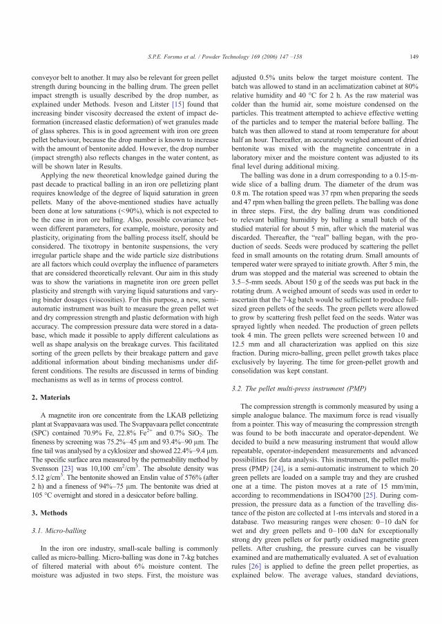
conveyor belt to another. It may also be relevant for green pelletstrength during bouncing in the balling drum. The green pelletimpact strength is usually described by the drop number, asexplained under Methods. Iveson and Litster [15] found thatincreasing binder viscosity decreased the extent of impact de-formation (increased elastic deformation) of wet granules madeof glass spheres. This is in good agreement with iron ore greenpellet behaviour, because the drop number is known to increasewith the amount of bentonite added. However, the drop number(impact strength) also reflects changes in the water content, aswill be shown later in Results.
Applying the new theoretical knowledge gained during thepast decade to practical balling in an iron ore pelletizing plantrequires knowledge of the degree of liquid saturation in greenpellets. Many of the above-mentioned studies have actuallybeen done at low saturations (b90%), which is not expected tobe the case in iron ore balling. Also, possible covariance bet-ween different parameters, for example, moisture, porosity andplasticity, originating from the balling process itself, should beconsidered. The tixotropy in bentonite suspensions, the veryirregular particle shape and the wide particle size distributionsare all factors which could overplay the influence of parametersthat are considered theoretically relevant. Our aim in this studywas to show the variations in magnetite iron ore green pelletplasticity and strength with varying liquid saturations and vary-ing binder dosages (viscosities). For this purpose, a new, semi-automatic instrument was built to measure the green pellet wetand dry compression strength and plastic deformation with highaccuracy. The compression pressure data were stored in a data-base, which made it possible to apply different calculations aswell as shape analysis on the breakage curves. This facilitatedsorting of the green pellets by their breakage pattern and gaveadditional information about binding mechanisms under dif-ferent conditions. The results are discussed in terms of bindingmechanisms as well as in terms of process control.
2. Materials
A magnetite iron ore concentrate from the LKAB pelletizingplant at Svappavaara was used. The Svappavaara pellet concentrate(SPC) contained 70.9% Fe, 22.8% Fe2+ and 0.7% SiO2. Thefineness by screening was 75.2%–45 μm and 93.4%–90 μm. Thefine tail was analysed by a cyklosizer and showed 22.4%–9.4 μm.The specific surface area measured by the permeability method bySvensson [23] was 10,100 cm2/cm3. The absolute density was5.12 g/cm3. The bentonite showed an Enslin value of 576% (after2 h) and a fineness of 94%–75 μm. The bentonite was dried at105 °C overnight and stored in a desiccator before balling.
3. Methods
3.1. Micro-balling
In the iron ore industry, small-scale balling is commonlycalled as micro-balling. Micro-balling was done in 7-kg batchesof filtered material with about 6% moisture content. Themoisture was adjusted in two steps. First, the moisture was
adjusted 0.5% units below the target moisture content. Thebatch was allowed to stand in an acclimatization cabinet at 80%relative humidity and 40 °C for 2 h. As the raw material wascolder than the humid air, some moisture condensed on theparticles. This treatment attempted to achieve effective wettingof the particles and to temper the material before balling. Thebatch was then allowed to stand at room temperature for abouthalf an hour. Thereafter, an accurately weighed amount of driedbentonite was mixed with the magnetite concentrate in alaboratory mixer and the moisture content was adjusted to itsfinal level during additional mixing.
The balling was done in a drum corresponding to a 0.15-m-wide slice of a balling drum. The diameter of the drum was0.8 m. The rotation speed was 37 rpm when preparing the seedsand 47 rpm when balling the green pellets. The balling was donein three steps. First, the dry balling drum was conditionedto relevant balling humidity by balling a small batch of thestudied material for about 5 min, after which the material wasdiscarded. Thereafter, the “real” balling began, with the pro-duction of seeds. Seeds were produced by scattering the pelletfeed in small amounts on the rotating drum. Small amounts oftempered water were sprayed to initiate growth. After 5 min, thedrum was stopped and the material was screened to obtain the3.5–5-mm seeds. About 150 g of the seeds was put back in therotating drum. Aweighed amount of seeds was used in order toascertain that the 7-kg batch would be sufficient to produce full-sized green pellets of the seeds. The green pellets were allowedto grow by scattering fresh pellet feed on the seeds. Water wassprayed lightly when needed. The production of green pelletstook 4 min. The green pellets were screened between 10 and12.5 mm and all characterization was applied on this sizefraction. During micro-balling, green pellet growth takes placeexclusively by layering. The time for green-pellet growth andconsolidation was kept constant.
3.2. The pellet multi-press instrument (PMP)
The compression strength is commonly measured by using asimple analogue balance. The maximum force is read visuallyfrom a pointer. This way of measuring the compression strengthwas found to be both inaccurate and operator-dependent. Wedecided to build a new measuring instrument that would allowrepeatable, operator-independent measurements and advancedpossibilities for data analysis. This instrument, the pellet multi-press (PMP) [24], is a semi-automatic instrument to which 20green pellets are loaded on a sample tray and they are crushedone at a time. The piston moves at a rate of 15 mm/min,according to recommendations in ISO4700 [25]. During com-pression, the pressure data as a function of the travelling dis-tance of the piston are collected at 1-ms intervals and stored in adatabase. Two measuring ranges were chosen: 0–10 daN forwet and dry green pellets and 0–100 daN for exceptionallystrong dry green pellets or for partly oxidised magnetite greenpellets. After crushing, the pressure curves can be visuallyexamined and are mathematically evaluated. A set of evaluationrules [26] is applied to define the green pellet properties, asexplained below. The average values, standard deviations,
149S.P.E. Forsmo et al. / Powder Technology 169 (2006) 147 –158
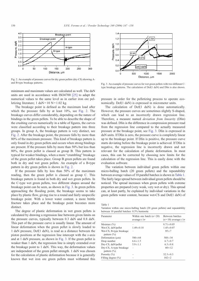
minimum and maximum values are calculated as well. The daNunits are used in accordance with ISO4700 [25] to adapt thenumerical values to the same level as in earlier iron ore pel-letizing literature; 1 daN=10 N=1.02 kg.
The breakage point is defined as the maximum load afterwhich the pressure falls by at least 10%, see Fig. 2. Thebreakage curves differ considerably, depending on the nature ofbindings in the green pellets. To be able to describe the shape ofthe crushing curves numerically in a table of figures, the curveswere classified according to their breakage pattern into threegroups. In group A, the breakage pattern is very distinct, seeFig. 2. After the breakage point, the pressure falls by more than80% of the maximum pressure. This kind of breakage pattern isonly found in dry green pellets and occurs when strong bindingsare present. If the pressure falls by more than 50% but less than80%, the green pellet is classed as group B. This pattern istypical for weaker bindings, when a more “crumbling” breakageof the green pellet takes place. Group B green pellets are foundboth in dry and wet green pellets. An example of a B-typepattern in dry green pellets is shown in Fig. 2.
If the pressure falls by less than 50% of the maximumreading, then the green pellet is classed as group C. Thisbreakage pattern is found in both dry and wet green pellets. Inthe C-type wet green pellets, two different shapes around thebreakage point can be seen, as shown in Fig. 3. In green pelletsapproaching the flooding point, the breakage seems to takeplace by plastic flow, giving rise to a round and fairly unspecificbreakage point. With a lower water content, a more brittlefracture takes place and the breakage point becomes moredistinct.
The degree of plastic deformation in wet green pellets iscalculated by drawing a regression line between given limits onthe pressure curves, typically between 0.3 daN and 0.8 daN.This part of the pressure curve is usually linear. The amount oflinear deformation when the green pellet is slowly loaded to1 daN pressure, Def(1 daN), is read as a distance between thepiston positions at the regression line intercept with the x-axisand at 1 daN pressure, as shown in Fig. 3. If the green pellet isweaker than 1 daN, the regression line is simply extended overthe breakage point to 1 daN. This way, the deformation valuesare independent of the green pellet strength. 1 daN was chosenfor the calculation of plastic deformation because it is generallyknown that wet iron ore green pellets must withstand this
pressure in order for the pelletizing process to operate eco-nomically. Def(1 daN) is expressed in micrometer units.
The calculation of Def(1 daN) is done automatically.However, the pressure curves are sometimes slightly S-shaped,which can lead to an incorrectly drawn regression line.Therefore, a measure named deviation from linearity (Dlin)was defined. Dlin is the difference in compression pressure readfrom the regression line compared to the actually measuredpressure at the breakage point, see Fig. 3. Dlin is expressed indaN units. If Dlin is zero, the pressure curve is completely linearup to the breakage point. If Dlin is positive, the pressure curvestarts deviating before the breakage point is achieved. If Dlin isnegative, the regression line is incorrectly drawn and notrelevant for the calculation of plastic deformation. In mostcases, this can be corrected by choosing new limits for thecalculation of the regression line. This is easily done with theevaluation software.
The variation between individual green pellets within onemicro-balling batch (20 green pellets) and the repeatabilitybetween average values of 10 parallel batches is shown in Table 1.The fairly large spread between individual green pellets should benoticed. The spread increases when green pellets with extremeproperties are prepared (very weak, very wet or dry). This spreadcan, at least partly, be explained by individual variations in thegreen pellets water content, because wet-CS and Def(1 daN) of
Fig. 3. An example of pressure curves for wet green pellets with two different C-type breakage patterns. The calculation of Def(1 daN) and Dlin is also shown.
Fig. 2. An example of pressure curves for dry green pellets (dry-CS) showing A-and B-type breakage patterns.
Table 1Variation within one micro-balling batch (20 green pellets) and repeatabilitybetween 10 parallel batches: 0.5% bentonite
Parameter Within one batch (n=20)average±1σ
Between batches(n=10) average±1σ
Moisture (%) – 8.71±0.05Wet-CS, daN/pellet 1.49±0.18 1.45±0.07Wet-CS, B-type breakagepattern (%)
– 95±7
Deformation (μm) 580±64 588±34Drop number 6.6±1.5 6.7±0.7Dry-CS, daN/pellet 5.9±1.1 6.3±0.8Dry-CS, A-type breakagepattern (%)
– 60±12
Porosity (%) – 32.3±0.3Filling degree (%) – 102±2
150 S.P.E. Forsmo et al. / Powder Technology 169 (2006) 147 –158
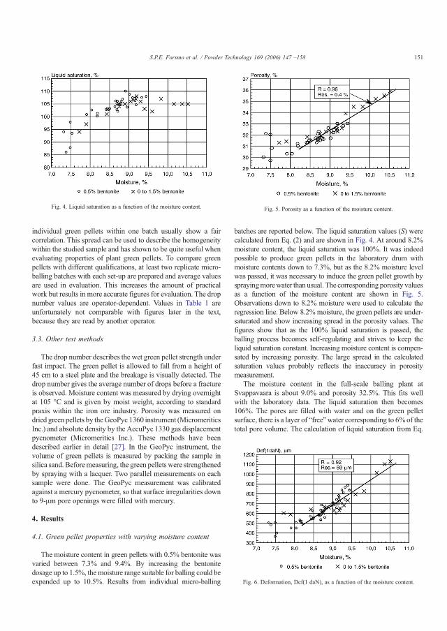
individual green pellets within one batch usually show a faircorrelation. This spread can be used to describe the homogeneitywithin the studied sample and has shown to be quite useful whenevaluating properties of plant green pellets. To compare greenpellets with different qualifications, at least two replicate micro-balling batches with each set-up are prepared and average valuesare used in evaluation. This increases the amount of practicalwork but results in more accurate figures for evaluation. The dropnumber values are operator-dependent. Values in Table 1 areunfortunately not comparable with figures later in the text,because they are read by another operator.
3.3. Other test methods
The drop number describes the wet green pellet strength underfast impact. The green pellet is allowed to fall from a height of45 cm to a steel plate and the breakage is visually detected. Thedrop number gives the average number of drops before a fractureis observed. Moisture content was measured by drying overnightat 105 °C and is given by moist weight, according to standardpraxis within the iron ore industry. Porosity was measured ondried green pellets by theGeoPyc 1360 instrument (MicromeriticsInc.) and absolute density by the AccuPyc 1330 gas displacementpycnometer (Micromeritics Inc.). These methods have beendescribed earlier in detail [27]. In the GeoPyc instrument, thevolume of green pellets is measured by packing the sample insilica sand. Beforemeasuring, the green pellets were strengthenedby spraying with a lacquer. Two parallel measurements on eachsample were done. The GeoPyc measurement was calibratedagainst a mercury pycnometer, so that surface irregularities downto 9-μm pore openings were filled with mercury.
4. Results
4.1. Green pellet properties with varying moisture content
The moisture content in green pellets with 0.5% bentonite wasvaried between 7.3% and 9.4%. By increasing the bentonitedosage up to 1.5%, the moisture range suitable for balling could beexpanded up to 10.5%. Results from individual micro-balling
batches are reported below. The liquid saturation values (S) werecalculated from Eq. (2) and are shown in Fig. 4. At around 8.2%moisture content, the liquid saturation was 100%. It was indeedpossible to produce green pellets in the laboratory drum withmoisture contents down to 7.3%, but as the 8.2% moisture levelwas passed, it was necessary to induce the green pellet growth bysprayingmorewater than usual. The corresponding porosity valuesas a function of the moisture content are shown in Fig. 5.Observations down to 8.2% moisture were used to calculate theregression line. Below 8.2%moisture, the green pellets are under-saturated and show increasing spread in the porosity values. Thefigures show that as the 100% liquid saturation is passed, theballing process becomes self-regulating and strives to keep theliquid saturation constant. Increasing moisture content is compen-sated by increasing porosity. The large spread in the calculatedsaturation values probably reflects the inaccuracy in porositymeasurement.
The moisture content in the full-scale balling plant atSvappavaara is about 9.0% and porosity 32.5%. This fits wellwith the laboratory data. The liquid saturation then becomes106%. The pores are filled with water and on the green pelletsurface, there is a layer of “free”water corresponding to 6% of thetotal pore volume. The calculation of liquid saturation from Eq.
Fig. 4. Liquid saturation as a function of the moisture content. Fig. 5. Porosity as a function of the moisture content.
Fig. 6. Deformation, Def(1 daN), as a function of the moisture content.
151S.P.E. Forsmo et al. / Powder Technology 169 (2006) 147 –158
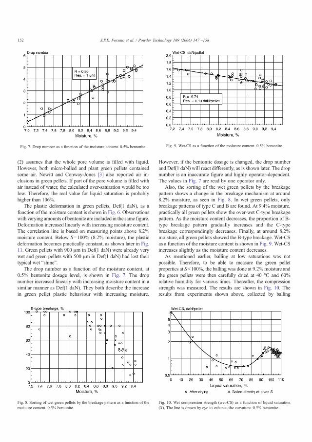
(2) assumes that the whole pore volume is filled with liquid.However, both micro-balled and plant green pellets containedsome air. Newitt and Conway-Jones [3] also reported air in-clusions in green pellets. If part of the pore volume is filled withair instead of water, the calculated over-saturation would be toolow. Therefore, the real value for liquid saturation is probablyhigher than 106%.
The plastic deformation in green pellets, Def(1 daN), as afunction of the moisture content is shown in Fig. 6. Observationswith varying amounts of bentonite are included in the same figure.Deformation increased linearly with increasing moisture content.The correlation line is based on measuring points above 8.2%moisture content. Below S=100% (8.2% moisture), the plasticdeformation becomes practically constant, as shown later in Fig.11. Green pellets with 900 μm in Def(1 daN) were already verywet and green pellets with 500 μm in Def(1 daN) had lost theirtypical wet “shine”.
The drop number as a function of the moisture content, at0.5% bentonite dosage level, is shown in Fig. 7. The dropnumber increased linearly with increasing moisture content in asimilar manner as Def(1 daN). They both describe the increasein green pellet plastic behaviour with increasing moisture.
However, if the bentonite dosage is changed, the drop numberand Def(1 daN) will react differently, as is shown later. The dropnumber is an inaccurate figure and highly operator-dependent.The values in Fig. 7 are read by one operator only.
Also, the sorting of the wet green pellets by the breakagepattern shows a change in the breakage mechanism at around8.2% moisture, as seen in Fig. 8. In wet green pellets, onlybreakage patterns of type C and B are found. At 9.4% moisture,practically all green pellets show the over-wet C-type breakagepattern. As the moisture content decreases, the proportion of B-type breakage pattern gradually increases and the C-typebreakage correspondingly decreases. Finally, at around 8.2%moisture, all green pellets showed the B-type breakage. Wet-CSas a function of the moisture content is shown in Fig. 9. Wet-CSincreases slightly as the moisture content decreases.
As mentioned earlier, balling at low saturations was notpossible. Therefore, to be able to measure the green pelletproperties at Sb100%, the balling was done at 9.2% moisture andthe green pellets were then carefully dried at 40 °C and 60%relative humidity for various times. Thereafter, the compressionstrength was measured. The results are shown in Fig. 10. Theresults from experiments shown above, collected by balling
Fig. 8. Sorting of wet green pellets by the breakage pattern as a function of themoisture content. 0.5% bentonite.
Fig. 9. Wet-CS as a function of the moisture content. 0.5% bentonite.Fig. 7. Drop number as a function of the moisture content. 0.5% bentonite.
Fig. 10. Wet compression strength (wet-CS) as a function of liquid saturation(S ). The line is drawn by eye to enhance the curvature. 0.5% bentonite.
152 S.P.E. Forsmo et al. / Powder Technology 169 (2006) 147 –158
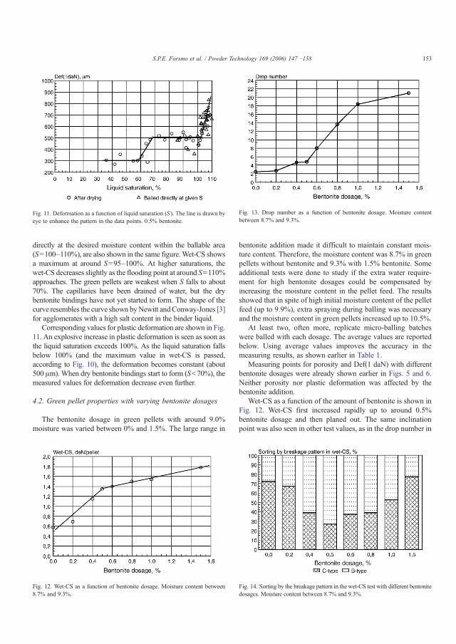
directly at the desired moisture content within the ballable area(S=100–110%), are also shown in the same figure.Wet-CS showsa maximum at around S=95–100%. At higher saturations, thewet-CS decreases slightly as the flooding point at around S=110%approaches. The green pellets are weakest when S falls to about70%. The capillaries have been drained of water, but the drybentonite bindings have not yet started to form. The shape of thecurve resembles the curve shown byNewitt andConway-Jones [3]for agglomerates with a high salt content in the binder liquid.
Corresponding values for plastic deformation are shown in Fig.11. An explosive increase in plastic deformation is seen as soon asthe liquid saturation exceeds 100%. As the liquid saturation fallsbelow 100% (and the maximum value in wet-CS is passed,according to Fig. 10), the deformation becomes constant (about500 μm).When dry bentonite bindings start to form (Sb70%), themeasured values for deformation decrease even further.
4.2. Green pellet properties with varying bentonite dosages
The bentonite dosage in green pellets with around 9.0%moisture was varied between 0% and 1.5%. The large range in
bentonite addition made it difficult to maintain constant mois-ture content. Therefore, the moisture content was 8.7% in greenpellets without bentonite and 9.3% with 1.5% bentonite. Someadditional tests were done to study if the extra water require-ment for high bentonite dosages could be compensated byincreasing the moisture content in the pellet feed. The resultsshowed that in spite of high initial moisture content of the pelletfeed (up to 9.9%), extra spraying during balling was necessaryand the moisture content in green pellets increased up to 10.5%.
At least two, often more, replicate micro-balling batcheswere balled with each dosage. The average values are reportedbelow. Using average values improves the accuracy in themeasuring results, as shown earlier in Table 1.
Measuring points for porosity and Def(1 daN) with differentbentonite dosages were already shown earlier in Figs. 5 and 6.Neither porosity nor plastic deformation was affected by thebentonite addition.
Wet-CS as a function of the amount of bentonite is shown inFig. 12. Wet-CS first increased rapidly up to around 0.5%bentonite dosage and then planed out. The same inclinationpoint was also seen in other test values, as in the drop number in
Fig. 11. Deformation as a function of liquid saturation (S ). The line is drawn byeye to enhance the pattern in the data points. 0.5% bentonite.
Fig. 12. Wet-CS as a function of bentonite dosage. Moisture content between8.7% and 9.3%.
Fig. 13. Drop number as a function of bentonite dosage. Moisture contentbetween 8.7% and 9.3%.
Fig. 14. Sorting by the breakage pattern in the wet-CS test with different bentonitedosages. Moisture content between 8.7% and 9.3%.
153S.P.E. Forsmo et al. / Powder Technology 169 (2006) 147 –158
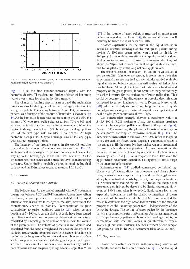
Fig. 13. First, the drop number increased slightly with thebentonite dosage. Thereafter, any further addition of bentoniteled to a very large increase in the drop number.
The change in binding mechanisms around the inclinationpoint can also be distinguished in the breakage pattern of thewet green pellets. The sorting between C- and B-type breakagepatterns as a function of the amount of bentonite is shown in Fig14. As the bentonite dosage was increased from 0% to 0.5%, theamount of C-type green pellets decreased from 70% to 30% andat larger bentonite dosages it started to increase again. When thebentonite dosage was below 0.5% the C-type breakage patternwas of the wet type with rounded curve shapes. At highbentonite dosages, the C-type breakage was of the dry type,with sharper breakage points.
The linearity of the pressure curves in the wet-CS test alsochanged as the amount of bentonite was increased, see Fig. 15.With low bentonite dosages, the pressure curves were linear all theway up to the breakage point and Dlin was near zero. As theamount of bentonite increased, the pressure curves started showingcurvature. Single bindings probably started to break before finalcollapse and the Dlin values ascended to around 0.16 daN.
5. Discussion
5.1. Liquid saturation and plasticity
The ballable area for the studied material with 0.5% bentonitedosage was between 8.2% and 9.4% moisture. Under these ballingconditions, the green pelletswere over-saturated (SN100%). Liquidsaturation was insensitive to changes in moisture, because of thecontemporary change in porosity. Over-saturation is quitecontradictory to earlier published data [3–6,8], which assumeflooding at S=100%. A certain shift in S could have been causedby different methods used in porosity determination. Porosity iscalculated by subtracting the volume of particles from the volumeof the green pellets. The volume of particles is well defined andcalculated from the sample weight and the absolute density of theparticles. However, the volume of green pellets depends on how theborderline on the green pellet surface is drawn—how much of thesurface roughness is considered to belong to the green pellet porestructure. In our case, the limit was drawn in such a way that thepore structure ends as the pore openings become larger than 9 μm
[27]. If the volume of green pellets is measured on moist greenpellets, as was done by Rumpf [4], the measured porosity willnaturally be larger and in all cases Sb100%.
Another explanation for the shift in the liquid saturationcould be eventual shrinkage of the wet green pellets duringdrying. A 10.0-mm green pellet would need to shrink by100 μm (1%) to explain the shift in the liquid saturation values.A dilatometer measurement showed a maximum shrinkage ofabout 10–20 μm, but the measurement was probably inaccurate,due to the plasticity of the original wet agglomerate.
The principal reason for this shift in saturation values couldnot be verified. Whatever the reason, it seems quite clear thatexperimental data are required to ascertain the applied scale forliquid saturation before comparison with earlier published datacan be done. Although the liquid saturation is a fundamentalproperty of the green pellets, it has been used very restrictivelyin earlier literature for the evaluation of green pellet data. Thiscould be because of the discrepancy in porosity determinationcompared to earlier fundamental work. Recently, Iveson et al.[28] published a study on predicting the growth rate of liquid-bound granules using raw-material properties as input data anddealing with pore saturations above 100%.
Wet compression strength showed a maximum value atS=95–100% (8.2% moisture). Also, the dominant breakagepattern in the wet green pellets was altered at this point (Fig. 8).Above 100% saturation, the plastic deformation in wet greenpellets started showing an explosive increase (Fig. 11). Theconclusion, then, is that in this work, S=100% refers to the pointwhere the capillary forces are as largest. The amount of water isjust enough to fill the pores. No free surface water is present andthe green pellets show low plasticity. At lower saturations, thebreakage is probably controlled by inter-particle friction, as wasshown by Pepin et al. [13]. As inter-particle forces take over, theagglomerates become brittle and the balling circuits start to surgein an uncontrollable manner.
Kristensen et al. [14] studied compressed cylindrical ag-glomerates of lactose, dicalcium phosphate and glass spheresusing aqueous binder liquids. They found that the agglomeratestrength is controlled mainly by porosity and liquid saturation.Our results show that below 100% saturation the green pelletproperties can, indeed, be described by liquid saturation. How-ever, as 100% saturation is exceeded, liquid saturation is notespecially informative and the plastic deformation of greenpellets should be used instead. Def(1 daN) values reveal if themoisture content is too high or too low in relation to the materialproperties of the incoming pellet feed—independently of thebentonite dosage. The sorting of green pellets by the breakagepattern gives supplementary information. An increasing amountof C-type breakage pattern with rounded breakage points, incombination with low Dlin values, is symptomatic of exces-sively high moisture contents. The measurement of one sample(20 green pellets) in the PMP instrument takes about 30 min.
5.2. Drop number
Elastic deformation increases with increasing amount ofbentonite, as shown by the drop number in Fig. 13. As the liquid
Fig. 15. Deviation from linearity (Dlin) with different bentonite dosages.Moisture content between 8.7% and 9.3%.
154 S.P.E. Forsmo et al. / Powder Technology 169 (2006) 147 –158
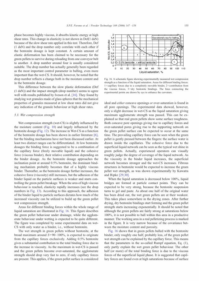
phase becomes highly viscous, it absorbs kinetic energy at highshear rates. This change in elasticity is not shown in Def(1 daN)because of the slow shear rate applied in this test. Therefore, Def(1 daN) and the drop number only correlate with each other ifthe bentonite dosage is kept constant. A certain amount ofelastic deformation has been claimed to be necessary for thegreen pellets to survive during reloading from one conveyor beltto another. A drop number around four is usually consideredsuitable. The drop number has actually generally been regardedas the most important control parameter in balling, even moreimportant than the wet-CS. It should, however, be noted that thedrop number reflects a change both in the moisture content andin the bentonite dosage.
This difference between the slow plastic deformation (Def(1 daN)) and the impact strength (drop number) seems to agreewell with results published by Iveson et al. [16]. They found bystudying wet granules made of glass spheres that the mechanicalproperties of granules measured at low shear rates did not giveany indication of the granule behaviour at high shear rates.
5.3. Wet compression strength
Wet compression strength (wet-CS) is slightly influenced bythe moisture content (Fig. 10) and largely influenced by thebentonite dosage (Fig. 12). The increase inWet-CS as a functionof the bentonite dosage has been shown in earlier literature [6],but the binding mechanisms have not been discussed earlier. Atleast two distinct ranges can be differentiated. At low bentonitedosages the binding force is suggested to be a combination ofthe capillary force (freely movable liquid) and the cohesiveforce (viscous binder), their relative contribution depending onthe binder dosage. As the bentonite dosage approaches theinclination point at around 0.5% bentonite, the dominant bind-ing mechanism probably becomes that of a highly viscousbinder. Thereafter, as the bentonite dosage further increases, thecohesive force (viscosity) still increases, but the adhesion of thebinder liquid on the particle surfaces is weaker and starts con-trolling the green pellet breakage. When the area of high viscousbehaviour is reached, elasticity rapidly increases (see the dropnumbers in Fig. 13). According to this approach, the adhesionof the binder liquid to particle surfaces dictates how much of theincreased viscosity can be utilized to build up the green pelletwet compression strength.
Areas for different binding forces within the whole range ofliquid saturation are illustrated in Fig. 16. This figure describesthe green pellet behaviour under drainage, while the agglom-erate behaviour under wetting is expected to be quite different.The figure was completed by some experimental data on wet-CS with only water as a binder, i.e., without bentonite.
The wet strength in green pellets without bentonite, at thebroad maximum around S=90–100%, is expected to originatefrom the capillary forces exclusively. Adding 0.5% bentonitegives a substantial contribution to the total binding force due tothe increase in viscosity. As the maximum in wet-CS is passedand the green pellets become over-saturated, the agglomeratestrength should drop very fast to zero, if only capillary forcesare present. This applies, if the green pellet surface is considered
ideal and either concave openings or over-saturation is found inall pore openings. The experimental data showed, however,only a slight decrease in wet-CS as the liquid saturation givingmaximum agglomerate strength was passed. This can be ex-plained so that real green pellets show some surface roughness.Both concave pore openings giving rise to capillary forces andover-saturated pores giving rise to the supporting network onthe green pellet surface can be expected to occur at the sametime. The prevailing capillary force can be seen when the greenpellet is gently pressed between the fingers: the surface water isdrawn inside the capillaries. The cohesive force due to thesuperficial liquid network can be seen as the typical wet shine ingreen pellets. Actually, experienced operators can visuallyroughly judge the degree of coverage of the liquid network. Asthe viscosity in the binder liquid increases, the superficialnetwork becomes stronger and the wet-CS increases. Fibrousstructures in bentonite would be expected to increase the greenpellet wet strength, as was shown experimentally by Kawatraand Ripke [29,30].
When the liquid saturation is decreased below 100%, liquidbridges are formed at particle contact points. They can beexpected to be very strong, because the bentonite suspensionturns to gel and paste. As about one half of the original waterhas been dried out, the wet green pellets are at their weakest.This takes place somewhere in the drying zones. After furtherdrying, dry bentonite bindings start forming and the green pelletstrength starts increasing exponentially. It should be noted thatalthough the green pellets are fairly strong at saturations below100%, it is not possible to ball within this area in a productivemanner. The working area in a real pelletizing process is markedin the figure. It is very narrow because of the covariance bet-ween the moisture content and porosity.
Fig. 16 shows that in green pellets balled with the bentonitebinder, only roughly one half, probably less, of the green pelletwet strength can be explained by the capillary force. This meansthat the parameters in the so-called Rumpf equation, Eq. (1),only partly explain the wet green pellet behaviour. The otherhalf (or more) of the total binding force is due to the viscousforces of the superficial liquid phase. It is suggested that capil-lary forces are found even at high saturations because of surface
Fig. 16. A schematic figure showing experimentally measured wet compressionstrength as a function of the liquid saturation. Areas for different binding forces:1=capillary forces due to a completely movable binder, 2=contribution fromthe viscous forces, 3=dry bentonite bindings. The lines connecting theexperimental points are drawn by eye to enhance the curvature.
155S.P.E. Forsmo et al. / Powder Technology 169 (2006) 147 –158
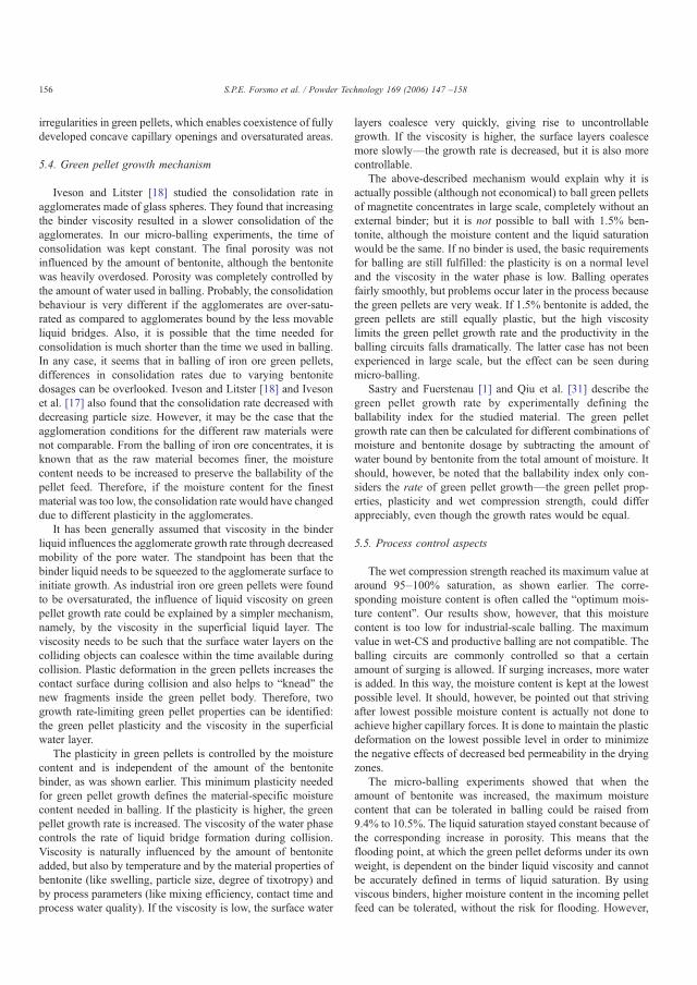
irregularities in green pellets, which enables coexistence of fullydeveloped concave capillary openings and oversaturated areas.
5.4. Green pellet growth mechanism
Iveson and Litster [18] studied the consolidation rate inagglomerates made of glass spheres. They found that increasingthe binder viscosity resulted in a slower consolidation of theagglomerates. In our micro-balling experiments, the time ofconsolidation was kept constant. The final porosity was notinfluenced by the amount of bentonite, although the bentonitewas heavily overdosed. Porosity was completely controlled bythe amount of water used in balling. Probably, the consolidationbehaviour is very different if the agglomerates are over-satu-rated as compared to agglomerates bound by the less movableliquid bridges. Also, it is possible that the time needed forconsolidation is much shorter than the time we used in balling.In any case, it seems that in balling of iron ore green pellets,differences in consolidation rates due to varying bentonitedosages can be overlooked. Iveson and Litster [18] and Ivesonet al. [17] also found that the consolidation rate decreased withdecreasing particle size. However, it may be the case that theagglomeration conditions for the different raw materials werenot comparable. From the balling of iron ore concentrates, it isknown that as the raw material becomes finer, the moisturecontent needs to be increased to preserve the ballability of thepellet feed. Therefore, if the moisture content for the finestmaterial was too low, the consolidation rate would have changeddue to different plasticity in the agglomerates.
It has been generally assumed that viscosity in the binderliquid influences the agglomerate growth rate through decreasedmobility of the pore water. The standpoint has been that thebinder liquid needs to be squeezed to the agglomerate surface toinitiate growth. As industrial iron ore green pellets were foundto be oversaturated, the influence of liquid viscosity on greenpellet growth rate could be explained by a simpler mechanism,namely, by the viscosity in the superficial liquid layer. Theviscosity needs to be such that the surface water layers on thecolliding objects can coalesce within the time available duringcollision. Plastic deformation in the green pellets increases thecontact surface during collision and also helps to “knead” thenew fragments inside the green pellet body. Therefore, twogrowth rate-limiting green pellet properties can be identified:the green pellet plasticity and the viscosity in the superficialwater layer.
The plasticity in green pellets is controlled by the moisturecontent and is independent of the amount of the bentonitebinder, as was shown earlier. This minimum plasticity neededfor green pellet growth defines the material-specific moisturecontent needed in balling. If the plasticity is higher, the greenpellet growth rate is increased. The viscosity of the water phasecontrols the rate of liquid bridge formation during collision.Viscosity is naturally influenced by the amount of bentoniteadded, but also by temperature and by the material properties ofbentonite (like swelling, particle size, degree of tixotropy) andby process parameters (like mixing efficiency, contact time andprocess water quality). If the viscosity is low, the surface water
layers coalesce very quickly, giving rise to uncontrollablegrowth. If the viscosity is higher, the surface layers coalescemore slowly—the growth rate is decreased, but it is also morecontrollable.
The above-described mechanism would explain why it isactually possible (although not economical) to ball green pelletsof magnetite concentrates in large scale, completely without anexternal binder; but it is not possible to ball with 1.5% ben-tonite, although the moisture content and the liquid saturationwould be the same. If no binder is used, the basic requirementsfor balling are still fulfilled: the plasticity is on a normal leveland the viscosity in the water phase is low. Balling operatesfairly smoothly, but problems occur later in the process becausethe green pellets are very weak. If 1.5% bentonite is added, thegreen pellets are still equally plastic, but the high viscositylimits the green pellet growth rate and the productivity in theballing circuits falls dramatically. The latter case has not beenexperienced in large scale, but the effect can be seen duringmicro-balling.
Sastry and Fuerstenau [1] and Qiu et al. [31] describe thegreen pellet growth rate by experimentally defining theballability index for the studied material. The green pelletgrowth rate can then be calculated for different combinations ofmoisture and bentonite dosage by subtracting the amount ofwater bound by bentonite from the total amount of moisture. Itshould, however, be noted that the ballability index only con-siders the rate of green pellet growth—the green pellet prop-erties, plasticity and wet compression strength, could differappreciably, even though the growth rates would be equal.
5.5. Process control aspects
The wet compression strength reached its maximum value ataround 95–100% saturation, as shown earlier. The corre-sponding moisture content is often called the “optimum mois-ture content”. Our results show, however, that this moisturecontent is too low for industrial-scale balling. The maximumvalue in wet-CS and productive balling are not compatible. Theballing circuits are commonly controlled so that a certainamount of surging is allowed. If surging increases, more wateris added. In this way, the moisture content is kept at the lowestpossible level. It should, however, be pointed out that strivingafter lowest possible moisture content is actually not done toachieve higher capillary forces. It is done to maintain the plasticdeformation on the lowest possible level in order to minimizethe negative effects of decreased bed permeability in the dryingzones.
The micro-balling experiments showed that when theamount of bentonite was increased, the maximum moisturecontent that can be tolerated in balling could be raised from9.4% to 10.5%. The liquid saturation stayed constant because ofthe corresponding increase in porosity. This means that theflooding point, at which the green pellet deforms under its ownweight, is dependent on the binder liquid viscosity and cannotbe accurately defined in terms of liquid saturation. By usingviscous binders, higher moisture content in the incoming pelletfeed can be tolerated, without the risk for flooding. However,
156 S.P.E. Forsmo et al. / Powder Technology 169 (2006) 147 –158
the Def(1 daN) measurements showed, that when these wet,high-bentonite green pellets were loaded with 1 daN pressure,they deformed equally as much as green pellets with a lowerbentonite dosage at similar moisture content. Therefore, even ifan excessively high moisture content in the incoming pellet feedcan be compensated in the balling circuits by adding slightlymore bentonite, the price is paid by negative effects later in theprocess due to the increased plasticity in green pellets.
In practice, variations occur both in the properties of theincoming pellet feed and in the moisture content. Also, theamount of bentonite addition is very small, only about 5 kg/tonne pellet feed, which makes it sensitive for dosing errors. It isnot always easy for the operator to know which of the twoparameters, the moisture content or the bentonite dosage, shouldbe adjusted. Our results show that plasticity in green pellets canonly be adjusted by changing the moisture content, not bychanging the bentonite dosage. Therefore, it is suggested thatthe balling circuits be controlled by the plastic deformation andthe compression strength in green pellets, instead of using therather inaccurate drop number.
The operators in the balling plant should also be aware thatchanging the bentonite dosage has different effects in the ballingprocess, depending on the current working area. A change in thebentonite dosage below the inclination point, where viscousforces still help to increase the green pellet wet strength, in-fluences both the wet-CS and the growth rate. Variations in thebentonite dosage above this level virtually only change thegrowth rate. The point of inclination is probably different fordifferent materials and binders.
6. Conclusions
Wet green pellets started showing plastic behaviour as theybecame over-saturated. At over-saturation, balling was a self-regulating process striving to keep the liquid saturation con-stant. At over-saturation, an explosive increase in plasticity withincreasing moisture content was seen due to the contemporaryincrease in porosity. No influence of the viscous bentonitebinder on green pellet plastic deformation under 1 daN pressurewas found. The flooding point, at which the green pelletsdeform under their own weight, was, however, shifted towardshigher moisture contents, as the amount of bentonite wasincreased.
As the green pellets are over-saturated, a supporting “net-work” of viscous liquid is formed on the green pellet surface.At least half, probably more, of the total binding force appearedto be due to the cohesive force of the viscous superficialnetwork. The other half (or less) of the total compressionstrength can be explained by the capillary force. Due to irregu-larities on green pellet surfaces, both fully developed concavepore openings and saturated areas are expected to be found atthe same time.
A new green pellet growth mechanism is suggested based onthe measured over-saturation. Two limiting green pellet prop-erties are identified. Firstly, the green pellet plasticity needs toexceed a minimum level to enable growth. For a given rawmaterial, the plasticity is controlled by the moisture content.
This limiting plasticity defines the material-specific moisturecontent needed in balling. Secondly, the viscosity in the liquidphase needs to be such that the superficial water on the growinggreen pellet and on the free pellet feed can coalesce within thetime available during collision. The results clearly point out theimportance of knowing whether the balling process should becontrolled by adjusting the moisture content (plasticity) or byadjusting the bentonite dosage (viscosity). These two operationsare not interchangeable—even if they would compensate ingrowth rate, the green-pellet properties would differ.
Plasticity is regarded as an important green pellet property inballing and should gain the status of a standard method in greenpellet characterization. Currently, the drop number and thecompression strength are the standard parameters for charac-terization, probably due to the simplicity of the measuringsystems. Today, rapid collection, storage and handling of largeamounts of data are not a problem and plasticity can be mea-sured with fair accuracy.
For the time being, typical values for plant green pelletplasticity are surveyed. The influence of variations in rawmaterial fineness on green pellet plasticity is being studied aswell. The applicability of the green pellet growth mechanismsuggested in this work will be verified under process conditions.The aim is to build a control strategy based on plastic defor-mation and compression strength of green pellets instead of therather inaccurate drop number. Accurate measurements of greenpellet strength and plasticity together with a better understand-ing of the binding and growth mechanisms constitute a solidbasis for further development of the process control system. Wealso hope that our experimental data will be of use to otherresearchers working with further development of the theoreticalaspects in agglomeration.
Acknowledgements
Funding from the Agricola Research Centre (ARC) at LuleåUniversity of Technology, Sweden and Luossavaara-Kiiruna-vaara AB (LKAB), Sweden, is gratefully acknowledged.
References
[1] K.V.S. Sastry, D.W. Fuerstenau, Ballability index to quantify agglomerategrowth by green pelletization, AIME Trans. (1972) 254–258.
[2] M. Tigerschiöld, P. Ilmoni, Fundamental factors influencing the strength ofgreen and burned pellets made from fine magnetite-ore concentrates, Proc.Blast Furnace, Coke Oven Raw Materials, Session on Ore and Agglo-meration, vol. 9, 1950, pp. 18–45.
[3] D.M. Newitt, J.M. Conway-Jones, A contribution to the theory andpractice of granulation, Trans. Inst. Chem. Eng. 36 (1958) 422–442.
[4] H. Rumpf, The strength of granules and agglomerates, in: W.A. Knepper(Ed.), Agglomeration, 1962, pp. 379–418.
[5] D.F. Ball, J. Dartnell, J. Davison, A. Grieve, R. Wild, Agglomeration inIron Ores, Heinemann Educational Books Ltd., London, 1973.
[6] K. Meyer, Pelletizing of Iron Ores, Springer-Verlag, Berlin, 1980.[7] J. Srb, Z. Ruzickova, Pelletization of Fines, Elsevier Science Publishing
Company, Inc., New York, 1988.[8] W. Pietsch, Size Enlargement by Agglomeration, John Wiley & Sons,
Chichester, 1991.[9] T.C. Eisele, S.K. Kawatra, A review of binders in iron ore pelletization,
Miner. Process. Extr. Metall. Rev. 24 (2003) 1–90.
157S.P.E. Forsmo et al. / Powder Technology 169 (2006) 147 –158

[10] H. Schubert, W. Herrmann, H. Rumpf, Deformation behaviour ofagglomerates under tensile stress, Powder Technol. 11 (1975) 121–131.
[11] B.J. Ennis, A microlevel-based characterization of granulation phenom-ena, Powder Technol. 65 (1991) 257–272.
[12] S.M. Iveson, N.W. Page, Tensile bond strength development between liquid-bound pellets during compression, Powder Technol. 117 (2001) 113–122.
[13] X. Pepin, S.J.R. Simons, S. Blanchon, D. Rosetti, G- Courraze, Hardnessof moist agglomerates in relation to interparticle friction, granule liquidcontent and nature, Powder Technol. 117 (2001) 123–138.
[14] H.G. Kristensen, P. Holm, T. Schaefer, Mechanical properties of moistagglomerates in relation to granulation mechanisms. Part 1. Deformabilityof moist, densified agglomerates, Powder Technol. 44 (1985) 227–237.
[15] S.M. Iveson, J.D. Litster, Liquid-bound granule impact deformation andcoefficient of restitution, Powder Technol. 99 (1998) 234–242.
[16] S.M. Iveson, N.W. Page, J.D. Litster, The importance of wet-powderdynamic mechanical properties in understanding granulation, PowderTechnol. 130 (2003) 97–101.
[17] S.M. Iveson, J.D. Litster, B.J. Ennis, Fundamental studies of granuleconsolidation: Part 1. Effects of binder content and binder viscosity,Powder Technol. 88 (1996) 15–20.
[18] S.M. Iveson, J.D. Litster, Fundamental studies of granule consolidation:Part 2. Quantifying the effects of particle and binder properties, PowderTechnol. 99 (1998) 243–250.
[19] P.J.T. Mills, J.P.K. Seville, P.C. Knight, M.J. Adams, The effect of binderviscosity on particle agglomeration in a low shear mixer/agglomerator,Powder Technol. 113 (2000) 140–147.
[20] S.T. Keningley, P.C. Knight, A.D. Marson, An investigation into theeffects of binder viscosity on agglomeration behaviour, Powder Technol.91 (1997) 95–103.
[21] C.O. Beale, J.E. Appleby, P. Butterfield, P.A. Young, ISI Spec. Rep. 78(1964) 50–62.
[22] H. Sportel, P. Beentjes, R. Rengersen, J. Droog, Quality of green iron orepellets, Ironmak. Steelmak. 24 (1997) 129–132.
[23] J. Svensson, Bestämning av specifika ytan på kross-och malgods enligtpermeabilitetsmetoden, Jernkontorets Ann., Stockholm 133 (1949) 33–86(in Swedish).
[24] Patent pending, SE 0500019-5, 2005.[25] International Standard ISO4700:1996(E). Iron ore pellets—determination
of crushing strength, 1996.[26] Patent pending, SE 0500018-7, 2005.[27] S.P.E. Forsmo, J.P. Vuori, The determination of porosity in iron ore green
pellets by packing in silica sand, Powder Technol. 159 (2005) 71–77.[28] S.M. Iveson, P.A.L. Wauters, S. Forrest, J.D. Litster, G.M.H. Meesters, B.
Scarlet, Growth regime map for liquid-bound granules: further develop-ment and experimental validation, Powder Technol. 117 (2001) 83–97.
[29] S.K. Kawatra, S.J. Ripke, Developing and understanding the bentonitefiber bonding mechanism, Miner. Eng. 14 (2001) 647–659.
[30] S.K. Kawatra, S.J. Ripke, Effects of bentonite fiber formation in iron orepelletization, Int. J. Miner. Process. 65 (2002) 141–149.
[31] G. Qiu, T. Jiang, X. Fan, D. Zhu, Z. Huang, Effects of binders on ballingbehaviours of iron ore concentrates, Scand. J. Metall. 33 (2004) 39–46.
158 S.P.E. Forsmo et al. / Powder Technology 169 (2006) 147 –158

ARTICLE IV
A study on plasticity and compression strength in wet iron ore green pellets related to real process variations in raw material
fineness
S.P.E. Forsmo, P-O. Samskog, B.M.T. Björkman
Submitted to Powder Technology (Feb 2006).
IV

1
A study on plasticity and compression strength in wet iron ore green pellets related to real process variations in raw material
fineness
S.P.E. Forsmoa,b,*, P-O. Samskoga,c, B.M.T. Björkmanb
aLKAB, R&D, SE-98381 Malmberget, Sweden. b Luleå University of Technology, Division of Process Metallurgy, SE-97187 Luleå, Sweden
cLuleå University of Technology, Division of Chemistry, SE-97187 Luleå, Sweden *Corresponding author. E-mail: [email protected] Fax: +46-970-30617
Abstract
The main binding force in wet iron ore green pellets has been found to be the cohesive force of the viscous binder. The wet compression strength (wet-CS) in green pellets is, however, also influenced by the green pellet plasticity. A certain degree of plasticity is needed to sustain the green pellet growth rate. Too much plasticity results in decreased bed permeability and production problems. As the plasticity increases, wet-CS decreases. The amount of moisture needed to create a given degree of plasticity depends on particle properties and on the particle size distribution. Therefore, it was of interest to study how wet-CS would be influenced by variations in raw material fineness, if the green pellet plasticity was kept constant, i.e. the green pellet properties would be compared under relevant industrial balling conditions. For this purpose, magnetite concentrates of different particle size distributions were balled in a laboratory drum and the moisture content for constant plasticity was determined for each of the materials.
No difference in green pellet wet-CS as a function of the raw material fineness was found when the bentonite binder was used and the plasticity was adjusted to a constant level. Green pellets prepared of raw materials with narrow size distributions were just as strong as those with broader ones. This is because the main binding force is the cohesive force of the viscous binder. In green pellets balled without the bentonite binder, wet-CS increased with increasing specific surface area in the raw material, in a similar manner as has been shown in earlier agglomeration literature. In this case, the capillary forces prevail. Comparison of wet-CS at constant moisture, instead of constant plasticity, would lead to erroneous conclusions. Fineness, or rather the slope of the particle size distribution curve, had a major impact on the moisture content needed for constant plasticity. If the slope increases, more water is needed to keep the plasticity on a constant level. Implications of these results in control of industrial iron ore balling circuits are discussed.
Key words: agglomeration; magnetite; iron ore; green pellets; plasticity; fineness
1. Introduction
Green pellet strength and plasticity are important parameters for the productivity of an iron ore pelletizing plant. Green pellet strength is described by two test values: the drop number and the compression strength. Drop number describes the green pellet strength during a fast impact, such as the impact that occurs during unloading from a conveyor belt. The drop number must be high enough for the green pellets to survive the transportation from the
2
balling circuits to the pelletizing machine. In earlier literature it has actually been regarded as the most important control parameter in balling, even more important than the compression strength [1, p. 107]. The drop number is, however, influenced by changes in both plasticity and elasticity: it increases with increasing moisture content and with increasing bentonite dosage [2]. From the drop number values, the operator cannot judge which of these two parameters should be adjusted. The drop number values are also fairly unreliable and operator dependent, because the breakage point is visually judged.
The green pellet strength under static load, e.g., in the pellet bed in the drying zones, is described by the wet compression strength (wet-CS). It needs to be high enough to assure minimum deformation and breakage. Plastic deformation and green pellet breakage decrease the permeability of the pellet bed in the drying and oxidation zones of the pelletizing machine, with negative consequences for both the pelletizing capacity and the pellet quality. The compression strength in wet iron ore green pellets is described in earlier textbooks [1,3,4,5] by the well-known capillary theory and the Rumpf equation (Eq. 1) [6]. It describes the agglomerate tensile strength at the capillary state, at about 90% filling degree, when a fully movable liquid is used as a binder. The filling degree (S) in wet agglomerates is defined as the volume of the binder liquid compared to the volume of pores and is calculated from Eq. (2).
cos11d
ac (1)
L
p
FFS 1
100100 (2)
Where c = green-pellet wet tensile strength due to the capillary force
a = constant = fractional porosity = surface tension
d = medium particle size = contact angle
S = filling degree (liquid saturation) F = moisture content by wet weight
p, L = density for particles and water, respectively
Today, the importance of viscous forces for the agglomerate strength is well recognized [7-13]. Also, the importance of agglomerate plasticity has been emphasized and intensively studied during recent years [14-17]. The rapid advancements during the past decade in understanding the fundamental processes in agglomeration were recently reviewed by Iveson et al. [18]. Many of these studies have, however, been done using glass spheres and Newtonian liquids as binders. Many of the studies also deal with high-shear agglomeration with relatively low filling degree in the agglomerates. When applying the results in balling of iron ore, the differences in agglomeration conditions should be recognized. Industrial iron ore green pellets are over-saturated and a supporting network of viscous liquid is formed on the green-pellet surface [2]. The strength of this network is initially controlled by the viscosity of the liquid phase. Therefore, in iron ore green pellets balled with a viscous binder, the main binding force originates from the viscous binder; only less than one half of the binding force is due to the capillary force. The most common binder in the iron ore industry is bentonite,

3
which is a tixotrop. Bentonite is known to increase the green pellet wet-CS, dry-CS and the drop number, though with very different mechanisms. Bentonite is also known to decrease the green-pellet growth rate and influence the growth mechanisms. Both the growth rate and the growth mechanism are, however, also influenced by green pellet plasticity. As high productivity in the balling circuits is one of the main objectives in iron ore agglomeration, a proper balance between the green pellet strength and growth rate needs to be established and sustained – even under variations in the pellet feed particle properties.
The importance of green pellet plasticity for the iron ore balling process has always been generally recognized [19-22], but possibly due to lack of reliable and practical measuring methods, it has been somewhat overlooked. In our earlier work [2] a measuring method was developed to calculate green pellet deformation when it is slowly loaded to 1 daN pressure. Twenty green pellets are automatically measured in one batch. The large number of measurements is definitively needed, because there are significant variations between individual green pellets, even within the same batch. The results showed that plasticity in green pellets (at slow shear rates), was not influenced by the bentonite binder. Therefore, although increasing the moisture content (plasticity) and decreasing the bentonite dosage (viscosity), both lead to a faster green pellet growth rate [23], they are not exchangeable in terms of green pellet quality.
Earlier experimental work [2] verified a broad maximum in wet-CS at around S = 100%, which is expected to correspond to fully developed capillary forces. The shift in saturation towards higher values than theoretical (S = 90%) can be explained by various definitions of the outer boarder line defining the green pellet volume in the porosity measurement [24]. It might actually be easier to keep in mind the oversaturated nature of the capillary openings in green pellets, when this state is described with saturation values exceeding 100%. The moisture content corresponding to the wet-CS maximum is sometimes called the “optimum moisture content”. It is, however, too low for industrial balling, because at this point the green pellets are fragile and show very little or no plasticity [2]. As the moisture content is increased above this level, the plasticity linearly increases – the green pellets grow faster and surging in the balling circuits decreases. This increase in productivity of balling is, however, done on the cost of increased deformation of green pellets and decreased bed permeability.
The amount of moisture needed to create a given plasticity is known to vary substantially between different materials. This material-specific moisture content is known to be dependent on parameters like particle size distribution, particle shape, surface roughness, inner porosity and wetting properties of the particles [1,3,5]. It is usually roughly estimated by practical balling experiments, by identifying the moisture content that gives about 4-5 drops in the drop number. However, because the drop number is influenced by the binder properties, as well, it only gives indirect information about green pellet plasticity. More accurate data on the moisture content needed in balling can be achieved by a direct measurement of the green pellet plasticity.
In an earlier, frequently quoted study on the variation of iron ore green pellet strength as a function of the raw material fineness [25], balling of the materials was done aiming at constant moisture in green pellets. However, if pellet feeds of largely different finenesses are balled using the same moisture content, the finest materials would probably be far too dry for large-scale balling and near to the maximum value in wet-CS and the coarsest materials would be over-wetted. Over-wetted green pellets are weaker – not due to the difference in fineness, but due to the difference in plasticity. To make a realistic judgement of changes in

4
wet-CS as a function of the raw material fineness, green pellets should be compared at equal plasticity. Also, from the general theory of particle packing, it is known that wide particle size distributions show a higher packing density than narrow ones [26]. However, this knowledge cannot be directly converted to a postulation that the wet strength in green pellets with wide particle size distributions would be higher, because the green pellet strength is only partly explained by the capillary forces. From everyday practical experience we know that raw materials with wider particle size distributions need to be balled with lower moisture content than raw materials with more narrow particle size distributions. Therefore, balling at constant plasticity would be needed for a meaningful comparison of the green pellet strength.
In the study by Urich and Hahn [25], only one raw material batch was used and ground further. In this kind of study, changes in the proportion of large and small particles always show co-variation. In an industrial concentrating plant, recycling loads and side streams with sculpted particle size distributions often appear. The mass rate and composition of these flows can vary. Natural variations in hardness of the mined ore can create variations in the fine tail. Even variations in unit operations before the final grinding stage can influence the shape of the particle size distribution. Therefore, in industrial processes, individual variations in the coarse and fine size fractions can occur. For process control and development purposes, the magnitude of the resulting changes in the green pellet wet-CS and plasticity need to be understood.
In this work, two groups of magnetite iron ore pellet concentrates with different particle size distributions were studied. The samples were collected from LKAB concentrating plants under varying running conditions. The samples showed large, but realistic, differences in fineness within both groups. The moisture content giving a constant plastic deformation in green pellets was determined for each material and the green pellet properties were then compared. The material-specific moisture contents were correlated to variations in raw material fineness to see if the moisture content needed in balling could be predicted from on-line particle size analysis of the pellet feeds.
2. Materials and methods
2.1 Materials
The magnetite pellet concentrate samples were collected from the LKAB (Luossavaara-Kiirunavaara AB, Sweden) Malmberget and Svappavaara concentrating plants by varying the feed rate into the grinding mills. The sampling was spread over a period of a few weeks at each of the plants. Thus, the samples also reflect some of the normal variations in ore quality. Five samples from Malmberget (MPC-1 to MPC-5) and six samples from Svappavaara (SPC-1 to SPC-6) were collected. Particle size data obtained by screening and cyclosizer and the specific surface areas for each of the materials are shown in Table 1. The samples are arranged in order of increasing %-45 μm fraction by screening within both sample groups. Particle sizing was done by using the laser diffraction measuring method as well, but because no additional information was gained, this data is not reported here.
The Malmberget magnetite pellet concentrate (MPC) is produced from the Malmberget magnetite ore, ground in ball mills in three stages, in open grinding circuits. The Svappavaara pellet concentrate (SPC) is produced using a certain size fraction of the magnetite ore from the LKAB Kiruna mine. The last grinding step at Svappavaara is done in a pebble mill

5
connected to a spiral classifier. To reach the target of around 10,000 cm2/cm3 in specific surface area in the pellet feed, SPC needs to be ground to 75% -45 μm and MPC only to 68% -45 μm. The difference in fine tail is because less fines is created from the Kiruna ore compared to the Malmberget ore. Differences in process layout contribute to the difference in the fine tail, as well. The samples marked as MPC-2 and SPC-3 in Table 1, represent typical process finenesses. The moisture content in balling is typically 8.2% for MPC and 9.0% for SPC. MPC typically contains 71.0% Fe, 22.9% Fe2+ and 0.5% SiO2. SPC typically contains 70.9% Fe, 22.8% Fe2+ and 0.7% SiO2.
Table 1. Particle sizing data on raw materials. Spec. surface Cyclosizer Screeningarea -7 μm -9 μm -13 μm -18 μm -26 μm -45 μm -63 μm -90 μm -125 μm
cm2/cm3 % % % % % % % % %
MPC-1 9491 16.5 21.6 29.2 35.2 49.0 66.1 77.5 88.5 94.9MPC-2 10038 17.2 22.9 31.3 37.7 52.2 68.8 80.3 90.5 96.0MPC-3 10774 18.8 24.9 34.1 41.0 55.8 71.7 81.7 91.3 96.6MPC-4 11606 20.8 27.1 36.5 43.4 58.5 75.4 84.9 93.3 97.4MPC-5 12386 20.3 27.0 37.0 44.4 59.9 77.2 86.7 94.7 98.1
SPC-1 9404 16.1 21.5 30.0 36.6 52.3 71.4 82.0 90.3 96.1SPC-2 9747 16.4 22.0 31.1 38.0 54.4 74.9 86.0 94.2 97.9SPC-3 10089 17.2 22.4 31.1 37.6 53.4 75.2 84.7 93.4 97.3SPC-4 10184 16.0 21.6 30.4 37.2 53.6 75.3 85.9 94.5 98.2SPC-5 10450 17.2 23.3 32.8 40.3 57.7 78.1 88.0 95.5 98.5SPC-6 11000 18.5 24.7 34.5 42.3 59.9 80.1 90.0 96.3 98.9
Bentonite was used as a binder in balling. The bentonite showed an Enslin value of 580% (after 2 h) and a fineness of 94% -75 μm. The bentonite was dried overnight at 105oC and stored in a desiccator before balling.
Each of the test materials was balled to green pellets with 0.5% bentonite binder at several different moisture contents covering the whole range of ballable moistures. The MPC samples were balled between 7.5 and 8.6% moisture contents, the SPC samples between 8.2 and 9.4%. At 8.2% moisture, the ballable areas for the MPC and SPC samples overlap and allow comparison of the green pellet properties at the same moisture content. The SPC samples were also balled with very low moisture content, 7.5%. All the test materials were also balled without bentonite.
2.2 Micro-balling
In the iron ore industry, small-scale balling is commonly called micro-balling. Micro-balling was done in 7-kg batches of filtered material with about 6% moisture content. The balling was done in a drum with a diameter of 0.8 m, according to methods described earlier [2]. Screened green pellets between 10 and 12.5 mm were used for testing. The properties of wet green pellets were analysed within 20 minutes from preparation.
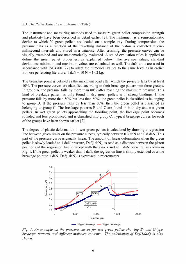
6
2.3 The Pellet Multi Press instrument (PMP)
The instrument and measuring methods used to measure green pellet compression strength and plasticity have been described in detail earlier [2]. The instrument is a semi-automatic device to which 20 green pellets are loaded on a sample tray. During compression, the pressure data as a function of the travelling distance of the piston is collected at one-millisecond intervals and stored in a database. After crushing, the pressure curves can be visually examined and are mathematically evaluated. A set of evaluation rules is applied to define the green pellet properties, as explained below. The average values, standard deviations, minimum and maximum values are calculated as well. The daN units are used in accordance with ISO4700 [27] to adapt the numerical values to the same level as in earlier iron ore pelletizing literature; 1 daN = 10 N = 1.02 kg.
The breakage point is defined as the maximum load after which the pressure falls by at least 10%. The pressure curves are classified according to their breakage pattern into three groups. In group A, the pressure falls by more than 80% after reaching the maximum pressure. This kind of breakage pattern is only found in dry green pellets with strong bindings. If the pressure falls by more than 50% but less than 80%, the green pellet is classified as belonging to group B. If the pressure falls by less than 50%, then the green pellet is classified as belonging to group C. The breakage patterns B and C are found in both dry and wet green pellets. In wet green pellets approaching the flooding point, the breakage point becomes rounded and less pronounced and is classified into group C. Typical breakage curves for each of the groups have been shown earlier [2].
The degree of plastic deformation in wet green pellets is calculated by drawing a regression line between given limits on the pressure curves, typically between 0.3 daN and 0.8 daN. This part of the pressure curve is usually linear. The amount of linear deformation when the green pellet is slowly loaded to 1 daN pressure, Def(1daN), is read as a distance between the piston positions at the regression line intercept with the x-axis and at 1 daN pressure, as shown in Fig. 1. If the green pellet is weaker than 1 daN, the regression line is simply extended over the breakage point to 1 daN. Def(1daN) is expressed in micrometers.
0.0
0.2
0.4
0.6
0.8
1.0
1.2
1.4
1.6
0 500 1000 1500 2000Distance, μm
Pre
ssur
e, d
aN
C-type breakage B-type breakage
Def(1daN)
8.7% 9.3%
B
C
Fig. 1. An example on the pressure curves for wet green pellets showing B- and C-type breakage patterns and different moisture contents. The calculation of Def(1daN) is also shown.
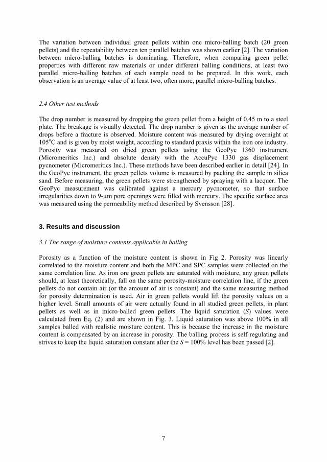
7
The variation between individual green pellets within one micro-balling batch (20 green pellets) and the repeatability between ten parallel batches was shown earlier [2]. The variation between micro-balling batches is dominating. Therefore, when comparing green pellet properties with different raw materials or under different balling conditions, at least two parallel micro-balling batches of each sample need to be prepared. In this work, each observation is an average value of at least two, often more, parallel micro-balling batches.
2.4 Other test methods
The drop number is measured by dropping the green pellet from a height of 0.45 m to a steel plate. The breakage is visually detected. The drop number is given as the average number of drops before a fracture is observed. Moisture content was measured by drying overnight at 105oC and is given by moist weight, according to standard praxis within the iron ore industry. Porosity was measured on dried green pellets using the GeoPyc 1360 instrument (Micromeritics Inc.) and absolute density with the AccuPyc 1330 gas displacement pycnometer (Micromeritics Inc.). These methods have been described earlier in detail [24]. In the GeoPyc instrument, the green pellets volume is measured by packing the sample in silica sand. Before measuring, the green pellets were strengthened by spraying with a lacquer. The GeoPyc measurement was calibrated against a mercury pycnometer, so that surface irregularities down to 9-μm pore openings were filled with mercury. The specific surface area was measured using the permeability method described by Svensson [28].
3. Results and discussion
3.1 The range of moisture contents applicable in balling
Porosity as a function of the moisture content is shown in Fig 2. Porosity was linearly correlated to the moisture content and both the MPC and SPC samples were collected on the same correlation line. As iron ore green pellets are saturated with moisture, any green pellets should, at least theoretically, fall on the same porosity-moisture correlation line, if the green pellets do not contain air (or the amount of air is constant) and the same measuring method for porosity determination is used. Air in green pellets would lift the porosity values on a higher level. Small amounts of air were actually found in all studied green pellets, in plant pellets as well as in micro-balled green pellets. The liquid saturation (S) values were calculated from Eq. (2) and are shown in Fig. 3. Liquid saturation was above 100% in all samples balled with realistic moisture content. This is because the increase in the moisture content is compensated by an increase in porosity. The balling process is self-regulating and strives to keep the liquid saturation constant after the S = 100% level has been passed [2].
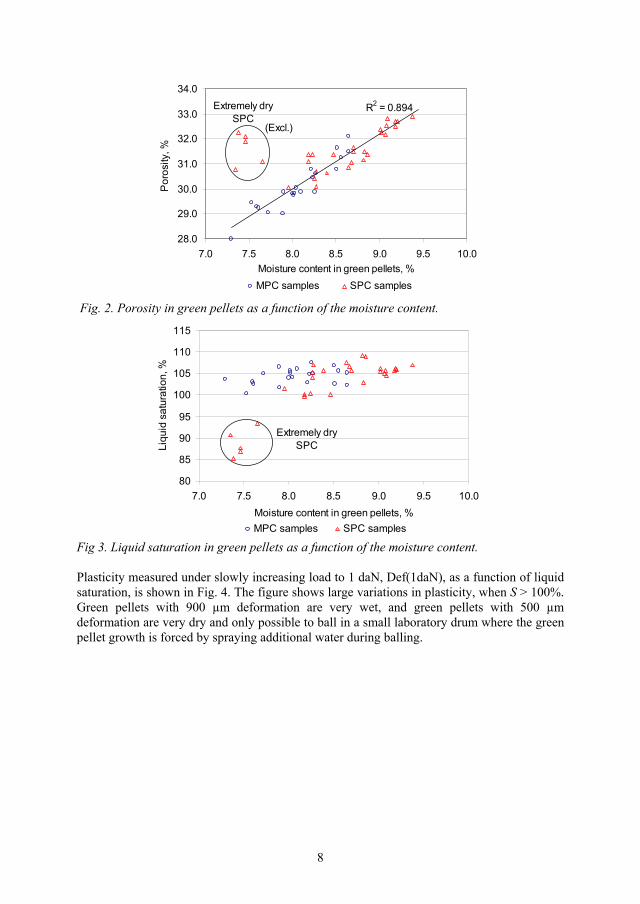
8
R2 = 0.894
28.0
29.0
30.0
31.0
32.0
33.0
34.0
7.0 7.5 8.0 8.5 9.0 9.5 10.0Moisture content in green pellets, %
Por
osity
, %
MPC samples SPC samples
Extremely dry SPC
(Excl.)
Fig. 2. Porosity in green pellets as a function of the moisture content.
80
85
90
95
100
105
110
115
7.0 7.5 8.0 8.5 9.0 9.5 10.0Moisture content in green pellets, %
Liqu
id s
atur
atio
n, %
MPC samples SPC samples
Extremely dry SPC
Fig 3. Liquid saturation in green pellets as a function of the moisture content.
Plasticity measured under slowly increasing load to 1 daN, Def(1daN), as a function of liquid saturation, is shown in Fig. 4. The figure shows large variations in plasticity, when S > 100%. Green pellets with 900 μm deformation are very wet, and green pellets with 500 μm deformation are very dry and only possible to ball in a small laboratory drum where the green pellet growth is forced by spraying additional water during balling.
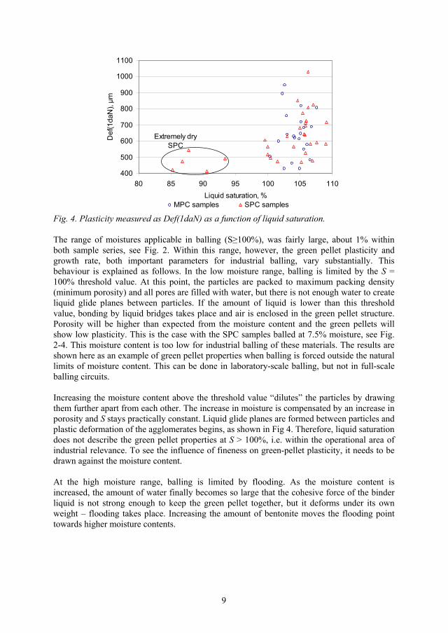
9
400
500
600
700
800
900
1000
1100
80 85 90 95 100 105 110Liquid saturation, %
Def
(1da
N), μm
MPC samples SPC samples
Extremely dry SPC
Fig. 4. Plasticity measured as Def(1daN) as a function of liquid saturation.
The range of moistures applicable in balling (S 100%), was fairly large, about 1% within both sample series, see Fig. 2. Within this range, however, the green pellet plasticity and growth rate, both important parameters for industrial balling, vary substantially. This behaviour is explained as follows. In the low moisture range, balling is limited by the S = 100% threshold value. At this point, the particles are packed to maximum packing density (minimum porosity) and all pores are filled with water, but there is not enough water to create liquid glide planes between particles. If the amount of liquid is lower than this threshold value, bonding by liquid bridges takes place and air is enclosed in the green pellet structure. Porosity will be higher than expected from the moisture content and the green pellets will show low plasticity. This is the case with the SPC samples balled at 7.5% moisture, see Fig. 2-4. This moisture content is too low for industrial balling of these materials. The results are shown here as an example of green pellet properties when balling is forced outside the natural limits of moisture content. This can be done in laboratory-scale balling, but not in full-scale balling circuits.
Increasing the moisture content above the threshold value “dilutes” the particles by drawing them further apart from each other. The increase in moisture is compensated by an increase in porosity and S stays practically constant. Liquid glide planes are formed between particles and plastic deformation of the agglomerates begins, as shown in Fig 4. Therefore, liquid saturation does not describe the green pellet properties at S > 100%, i.e. within the operational area of industrial relevance. To see the influence of fineness on green-pellet plasticity, it needs to be drawn against the moisture content.
At the high moisture range, balling is limited by flooding. As the moisture content is increased, the amount of water finally becomes so large that the cohesive force of the binder liquid is not strong enough to keep the green pellet together, but it deforms under its own weight – flooding takes place. Increasing the amount of bentonite moves the flooding point towards higher moisture contents.
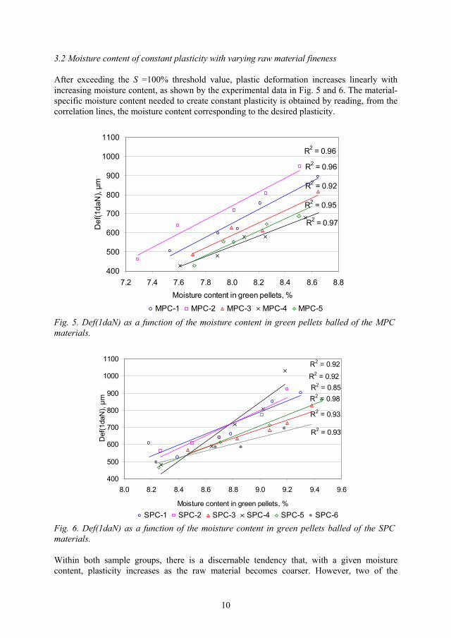
10
3.2 Moisture content of constant plasticity with varying raw material fineness
After exceeding the S =100% threshold value, plastic deformation increases linearly with increasing moisture content, as shown by the experimental data in Fig. 5 and 6. The material- specific moisture content needed to create constant plasticity is obtained by reading, from the correlation lines, the moisture content corresponding to the desired plasticity.
R2 = 0.96
R2 = 0.96
R2 = 0.92
R2 = 0.97
R2 = 0.95
400
500
600
700
800
900
1000
1100
7.2 7.4 7.6 7.8 8.0 8.2 8.4 8.6 8.8Moisture content in green pellets, %
Def
(1da
N), μm
MPC-1 MPC-2 MPC-3 MPC-4 MPC-5
Fig. 5. Def(1daN) as a function of the moisture content in green pellets balled of the MPC materials.
R2 = 0.85R2 = 0.98
R2 = 0.93
R2 = 0.92
R2 = 0.92
R2 = 0.93
400
500
600
700
800
900
1000
1100
8.0 8.2 8.4 8.6 8.8 9.0 9.2 9.4 9.6
Moisture content in green pellets, %
Def
(1da
N), μm
SPC-1 SPC-2 SPC-3 SPC-4 SPC-5 SPC-6
Fig. 6. Def(1daN) as a function of the moisture content in green pellets balled of the SPC materials.
Within both sample groups, there is a discernable tendency that, with a given moisture content, plasticity increases as the raw material becomes coarser. However, two of the
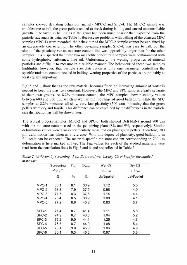
11
samples showed deviating behaviour, namely MPC-2 and SPC-4. The MPC-2 sample was troublesome to ball, the green pellets tended to break during balling and caused uncontrollable growth. It behaved in balling as if the grind had been much coarser than expected from the particle size analysis data, see Table 1. Because no problems with balling of the coarsest MPC sample (MPC-1) were recorded, the behaviour of the MPC-2 sample cannot be explained by an excessively coarse grind. The other deviating sample, SPC-4, was easy to ball, but the slope of the plasticity versus moisture content line was appreciably larger than for the other samples. It is suspected that these two magnetite concentrate samples were contaminated with some hydrophobic substance, like oil. Unfortunately, the wetting properties of mineral particles are difficult to measure in a reliable manner. The behaviour of these two samples highlights, however, that particle size distribution is only one parameter controlling the specific moisture content needed in balling, wetting properties of the particles are probably at least equally important.
Fig. 5 and 6 show that as the raw material becomes finer, an increasing amount of water is needed to keep the plasticity constant. However, the MPC and SPC samples clearly separate to their own groups. At 8.2% moisture content, the MPC samples show plasticity values between 600 and 850 μm, which is well within the range of good ballability, while the SPC samples at 8.2% moisture, all show very low plasticity (500 μm) indicating that the green pellets were dry and fragile. This difference can be explained by the differences in the particle size distribution, as will be shown later.
The typical process samples, MPC-2 and SPC-3, both showed Def(1daN) around 700 μm with the moisture content used in the pelletizing plant (8% and 9%, respectively). Similar deformation values were also experimentally measured on plant green pellets. Therefore, 700 μm deformation was taken as a reference. With this degree of plasticity, good ballability in full scale can be expected. The material-specific moisture content corresponding to 700 μm deformation is here marked as F700. The F700 values for each of the studied materials were read from the correlation lines in Fig. 5 and 6, and are collected in Table 2.
Table 2. %-45 μm by screening, F700, D45-13 and wet-CS/dry-CS at F700 for the studied materials.
Screening F700 D45-13 Wet-CS Dry-CS -45 μm at F700 at F700
% % % daN/pellet daN/pellet
MPC-1 66.1 8.1 36.9 1.12 5.0MPC-2 68.8 7.9 37.5 0.98 4.0MPC-3 71.7 8.3 37.6 1.14 4.4MPC-4 75.4 8.5 38.9 1.08 4.1MPC-5 77.2 8.6 40.2 0.83 3.7
SPC-1 71.4 8.7 41.4 1.11 5.8SPC-2 74.9 8.7 43.8 1.04 5.2SPC-3 75.2 9.0 44.1 1.25 4.3SPC-4 75.3 8.7 44.9 1.08 5.4SPC-5 78.1 9.0 45.3 1.06 4.9SPC-6 80.1 9.3 45.6 0.97 3.6
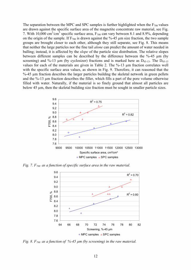
12
The separation between the MPC and SPC samples is further highlighted when the F700 valuesare drawn against the specific surface area of the magnetite concentrate raw material, see Fig. 7. With 10,000 cm2/cm3 specific surface area, F700 can vary between 8.1 and 8.9%, depending on the origin of the sample. If F700 is drawn against the %-45 μm size fraction, the two sample groups are brought closer to each other, although they still separate, see Fig. 8. This means that neither the large particles nor the fine tail alone can predict the amount of water needed in balling; instead, it is affected by the slope of the particle size distribution. The relative slopes between different samples can be described by the difference between the %-45 μm (by screening) and %-13 μm (by cyclosizer) fractions and is marked here as D45-13. The D45-13values for each of the materials are given in Table 2. The %-13 μm fraction correlates well with the specific surface area values, as shown in Fig. 9. Therefore, it can reasoned that the %-45 μm fraction describes the larger particles building the skeletal network in green pellets and the %-13 μm fraction describes the filler, which fills a part of the pore volume otherwise filled with water. Naturally, if the material is so finely ground that almost all particles are below 45 μm, then the skeletal building size fraction must be sought in smaller particle sizes.
R2 = 0.75
R2 = 0.82
7.67.88.08.28.48.68.89.09.29.49.6
9000 9500 10000 10500 11000 11500 12000 12500 13000Specific surface area, cm²/cm³
F700
, %
MPC samples SPC samples
Fig. 7. F700 as a function of specific surface area in the raw material.
R2 = 0.70
R2 = 0.80
7.6
7.8
8.0
8.2
8.4
8.6
8.8
9.0
9.2
9.4
9.6
64 66 68 70 72 74 76 78 80 82Screening, %-45 μm
F700
, %
MPC samples SPC samples
Fig. 8. F700 as a function of %-45 μm (by screening) in the raw material.

13
R2 = 0.92
9000
9500
10000
10500
11000
11500
12000
12500
13000
28 30 32 34 36 38Cyklosizer, %-13 μm
Spe
cific
sur
face
are
a, c
m²/c
m³
MPC samples SPC samples
Fig. 9. Specific surface area as a function of the %-13 μm fraction (by cyclosizer) in the magnetite concentrate raw material.
F700 is plotted against the slope of the particle size distributions, D45-13, in Fig 10. Both the MPC and SPC samples are collected on the same correlation line with a prediction error of only 0.2% in F700. An increase in slope means that the particle size distribution becomes narrower. As the size difference between the smallest and largest particles decreases, the packing density decreases (porosity increases), as is known from the general theory of packing of dry particles, comprehensively reviewed by German [26]. Therefore, with increasing slope, more water is needed to fill the voids between the particles.
The raw material fineness analysis in Table 1 shows, that varying the mill feed rate causes only relatively small changes in the %-13 μm fraction (expressed in mass per cent), compared to changes in the %-45 μm fraction. Therefore, the slope is in practice dominated by changes in the %-45 μm fraction and only a moderate adjustment for changes in the specific surface area (%-13 μm) is needed. This explains why the correlation lines for F700 against %-45 μm (Fig. 8) are closer to each other than the corresponding lines drawn against specific surface area (Fig. 7). The slope of the particle size distribution increases as the ‘degree of grinding’, %-45 μm, increases.
R2 = 0.81
7.6
7.8
8.0
8.2
8.4
8.6
8.8
9.0
9.2
9.4
9.6
34 36 38 40 42 44 46 48D45-13, %
F700
, %
MPC samples SPC samples
Fig. 10. The material specific moisture content (F700) as a function of the slope of the particle size distribution (D45-13) in the magnetite concentrate raw materials.

14
According to general practical knowledge, the specific surface area in balling of iron ore needs to exceed around 9,500 cm2/cm3 in order to assure good ballability of the raw material. Therefore, the ‘degree of grinding’, %-45 μm, needs to be chosen so that this threshold value in specific surface area is exceeded and the moisture content needs to be adjusted so that the desired degree if plasticity is reached. Probably the most detrimental factor for a balling process would be continuous variation in slope – the moisture content in balling would be alternately too high and too low compared to the F700 of the incoming pellet feed.
The difference in plastic behaviour in green pellets balled from the MPC and SPC materials can also be seen in the sorting of green pellets by their breakage pattern. Wet green pellets with C type breakage pattern typically break through plastic flow, as was described earlier. The amount of green pellets with C type breakage pattern as a function of the moisture content is shown in Fig. 11. The MPC and SPC samples clearly separate to their own groups, even if the large variation in fineness within each sample group adds to the spread of the measurements. At 8.2% moisture content, on average about 70% of the green pellets balled of the MPC materials (of any fineness) showed breakage through plastic flow. In green pellets balled from the SPC materials at 8.2% moisture content, practically no C-type breakage pattern was found. If the proportion of green pellets showing C-type breakage pattern is drawn against plasticity, Def(1daN), the experimental points for the MPC and SPC samples practically merge on the same correlation line, although the experimental spread is fairly large, see Fig. 12. The correlation occurs because the C-type breakage pattern and Def(1daN), both describe the same property of wet green pellets.
010
2030
405060
7080
90100
7.0 7.5 8.0 8.5 9.0 9.5 10.0Moisture content in green pellets, %
C-ty
pe b
reak
age,
%
MPC samples SPC samples
Fig. 11. The amount of green pellets showing C-type breakage pattern in wet-CS test as a function of the moisture content.
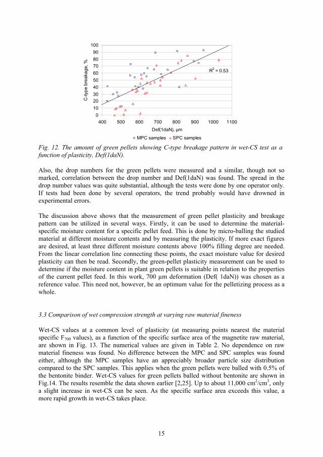
15
R2 = 0.53
0102030405060708090
100
400 500 600 700 800 900 1000 1100Def(1daN), μm
C-ty
pe b
reak
age,
%
MPC samples SPC samples
Fig. 12. The amount of green pellets showing C-type breakage pattern in wet-CS test as a function of plasticity, Def(1daN).
Also, the drop numbers for the green pellets were measured and a similar, though not so marked, correlation between the drop number and Def(1daN) was found. The spread in the drop number values was quite substantial, although the tests were done by one operator only. If tests had been done by several operators, the trend probably would have drowned in experimental errors.
The discussion above shows that the measurement of green pellet plasticity and breakage pattern can be utilized in several ways. Firstly, it can be used to determine the material-specific moisture content for a specific pellet feed. This is done by micro-balling the studied material at different moisture contents and by measuring the plasticity. If more exact figures are desired, at least three different moisture contents above 100% filling degree are needed. From the linear correlation line connecting these points, the exact moisture value for desired plasticity can then be read. Secondly, the green-pellet plasticity measurement can be used to determine if the moisture content in plant green pellets is suitable in relation to the properties of the current pellet feed. In this work, 700 μm deformation (Def( 1daN)) was chosen as a reference value. This need not, however, be an optimum value for the pelletizing process as a whole.
3.3 Comparison of wet compression strength at varying raw material fineness
Wet-CS values at a common level of plasticity (at measuring points nearest the material specific F700 values), as a function of the specific surface area of the magnetite raw material, are shown in Fig. 13. The numerical values are given in Table 2. No dependence on raw material fineness was found. No difference between the MPC and SPC samples was found either, although the MPC samples have an appreciably broader particle size distribution compared to the SPC samples. This applies when the green pellets were balled with 0.5% of the bentonite binder. Wet-CS values for green pellets balled without bentonite are shown in Fig.14. The results resemble the data shown earlier [2,25]. Up to about 11,000 cm2/cm3, only a slight increase in wet-CS can be seen. As the specific surface area exceeds this value, a more rapid growth in wet-CS takes place.

16
0.400.500.600.700.800.901.001.101.201.301.40
9000 9500 10000 10500 11000 11500 12000 12500 13000Specific surface area, cm²/cm³
Wet
-CS
, daN
/pel
let
MPC samples SPC samples
Fig. 13. Wet-CS as a function of the specific surface area at constant plasticity. Balled with 0.5% bentonite.
R2 = 0.93
0.400.500.600.700.800.901.001.101.201.301.40
9000 9500 10000 10500 11000 11500 12000 12500 13000Specific surface area, cm²/cm³
Wet
-CS
, daN
/pel
let
MPC samples SPC samples
Fig. 14. Wet-CS as a function of the specific surface area at constant plasticity. Balled without bentonite.
The comparison of wet-CS values at a constant moisture content of 8.2% (and with 0.5% bentonite) is shown in Fig. 15. If the influence of raw material fineness would be judged by using a constant moisture content in balling, the two coarsest MPC samples (MPC-1 and MPC-2) would be classified as too coarse, because of the weak green pellets. Also, the SPC green pellets appear to be stronger than the MPC green pellets. This is, however, only an effect of differences in plasticity. The moisture content of 8.2% is high for the MPC-1 and MPC-2 materials. The green pellets show high plasticity and become weaker. For the SPC materials, 8.2% moisture content is low and wet-CS is near to the maximum value. However, large-scale balling at this low moisture content would probably not be feasible.
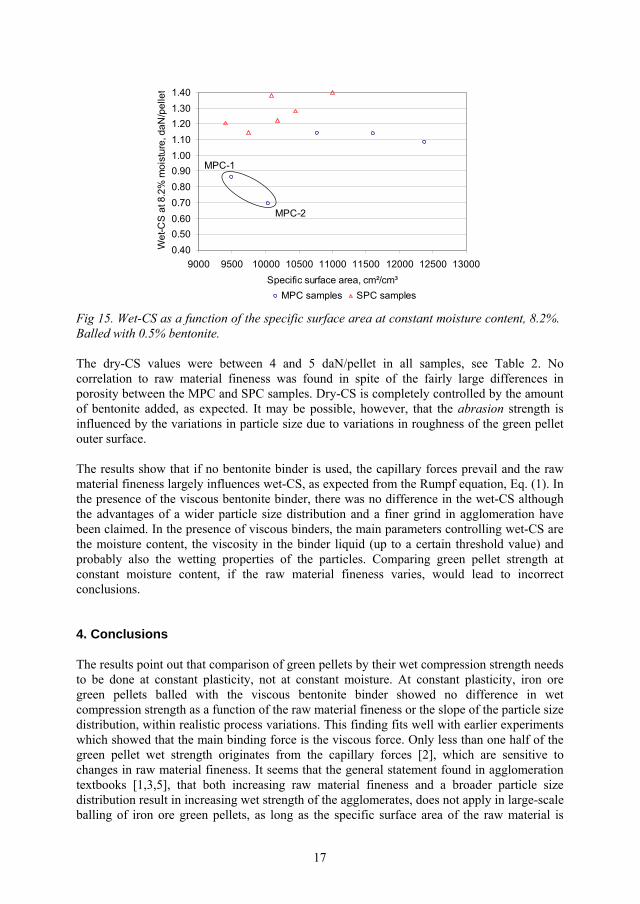
17
0.400.500.600.700.800.901.001.101.201.301.40
9000 9500 10000 10500 11000 11500 12000 12500 13000Specific surface area, cm²/cm³
Wet
-CS
at 8
.2%
moi
stur
e, d
aN/p
elle
t
MPC samples SPC samples
MPC-1
MPC-2
Fig 15. Wet-CS as a function of the specific surface area at constant moisture content, 8.2%. Balled with 0.5% bentonite.
The dry-CS values were between 4 and 5 daN/pellet in all samples, see Table 2. No correlation to raw material fineness was found in spite of the fairly large differences in porosity between the MPC and SPC samples. Dry-CS is completely controlled by the amount of bentonite added, as expected. It may be possible, however, that the abrasion strength is influenced by the variations in particle size due to variations in roughness of the green pellet outer surface.
The results show that if no bentonite binder is used, the capillary forces prevail and the raw material fineness largely influences wet-CS, as expected from the Rumpf equation, Eq. (1). In the presence of the viscous bentonite binder, there was no difference in the wet-CS although the advantages of a wider particle size distribution and a finer grind in agglomeration have been claimed. In the presence of viscous binders, the main parameters controlling wet-CS are the moisture content, the viscosity in the binder liquid (up to a certain threshold value) and probably also the wetting properties of the particles. Comparing green pellet strength at constant moisture content, if the raw material fineness varies, would lead to incorrect conclusions.
4. Conclusions
The results point out that comparison of green pellets by their wet compression strength needs to be done at constant plasticity, not at constant moisture. At constant plasticity, iron ore green pellets balled with the viscous bentonite binder showed no difference in wet compression strength as a function of the raw material fineness or the slope of the particle size distribution, within realistic process variations. This finding fits well with earlier experiments which showed that the main binding force is the viscous force. Only less than one half of the green pellet wet strength originates from the capillary forces [2], which are sensitive to changes in raw material fineness. It seems that the general statement found in agglomeration textbooks [1,3,5], that both increasing raw material fineness and a broader particle size distribution result in increasing wet strength of the agglomerates, does not apply in large-scale balling of iron ore green pellets, as long as the specific surface area of the raw material is

18
within the ballable area. This information is of great importance for the control of the balling circuits: variations in the grind of the pellet feed would not show in the green pellet wet compression strength as long as the green pellet plasticity is kept constant by adjusting the moisture content. Other green pellet properties like the abrasion strength, the growth rate, the oxidation rate in case of magnetite iron ore and the sintering rate are, however, all expected to change with changes in raw material fineness.
Fineness, or rather the slope of the particle size distribution curve, has a major impact on the moisture content needed to create plasticity in green-pellets. The moisture content giving rise to 700 μm plastic deformation during slow compression to 1 daN pressure is marked as F700and is a material-specific parameter. Variations in F700, were better described by the large particles (%-45 μm) than the small ones (%-13 μm or the specific surface area). Best correlation was obtained using the slope of the particle size distribution, here expressed as a difference between the size fractions %-45 μm and %-13 μm. The correlation error was only ±0.2% in F700. Naturally, if the process variations in the slope of the particle size distribution are small, F700 can be predicted by only measuring the %-45 μm fraction. This assumption is actually made today, because the grinding of MPC and SPC pellet feeds is controlled by the %-45 μm fraction exclusively. If the slope increases, the amount of water needs to be increased to keep the plasticity in green pellets constant.
In controlling full-scale balling, it is not enough just to keep the moisture content constant, because variations in raw material fineness and particle wetting properties occur. The larger the difference between the actual moisture content and F700, the larger will be the effect in balling kinetics due to the difference in plasticity. The judgement if balling is running “wet” or “dry” can now be based on the measurement of green pellet plasticity and breakage pattern.
The concept of constant plasticity in green pellets (F700) and the ability to predict F700 from the slope of the particle sizing curve (D45-13),can hopefully be used to improve the uniformity of the balling process. In this work, particle sizing was done by screening and cyclosizer, both fairly time consuming methods. In plant applications, the control of grinding needs to be based on on-line particle size measurement, especially if variations in the slope of the particle size distribution is expected. A feasibility study for on-line measurement using laser diffraction has been started.
In the case of magnetite pellet concentrates, the particle size distribution is also an important issue influencing the oxidation of magnetite to hematite. It is a highly exothermic reaction and largely influences the final pellet quality. Since the influence of variations in the magnetite concentrate fineness on the green pellets strength and porosity (moisture content) is now known, further optimization of the grinding processes towards higher metallurgical quality in pellets will be facilitated.
Acknowledgements
This work has been performed within the Agricola Research Centre (ARC) at Luleå University of Technology, Sweden. ARC is a research programme funded by the Swedish Foundation for Strategic Research, LKAB (Luossavaara-Kiirunavaara AB) and Boliden Mineral AB.

19
References
1. D.F. Ball, J. Dartnell, J. Davison, A. Grieve, R. Wild, Agglomeration in iron ores, Heinemann Educational Books Ltd., London, 1973.
2. S.P.E. Forsmo, A.J. Apelqvist, B.M.T. Björkman, P-O. Samskog, Binding mechanisms in wet iron ore green pellets with a bentonite binder, Powder Technol. 169 (2006) 147-158.
3. K. Meyer, Pelletizing of iron ores, Springer-Verlag, Berlin, 1980.
4. J. Srb, Z. Ruzickova, Pelletization of fines, Elsevier Science Publishing Company, Inc., New York, 1988.
5. W. Pietsch, Size Enlargement by Agglomeration, John Wiley & Sons, Chichester, England, 1991.
6. H. Rumpf, in: W. A. Knepper (Ed.), The Strength of Granules and Agglomerates, AIME, Agglomeration, Interscience, New-York, 1962, pp. 379-418.
7. B.J. Ennis, G.I. Tardos, R. Pfeffer, A microlevel-based characterization of granulation phenomena, Powder Technol. 65 (1991) 257-272.
8. S.M. Iveson, J.D. Litster, B.J. Ennis, Fundamental studies of granule consolidation. Part 1: Effects of binder content and binder viscosity, Powder Technol. 88 (1996) 15-20.
9. S.T. Keningley, P.C. Knight, A.D. Marson, An investigation into the effects of binder viscosity on agglomeration behaviour, Powder Technol. 91 (1997) 95-103.
10. P.J.T. Mills, J.P.K. Seville, P.C. Knight, M.J. Adams, The effect of binder viscosity on particle agglomeration in a low shear mixer/agglomerator, Powder Technol. 113 (2000) 140-147.
11. P.C. Knight, Structuring agglomerated products for improved performance, Powder Technol. 119 (2001) 14-25.
12. X. Pepin, S.J.R. Simons, S. Blanchon, D. Rossetti, G. Couarraze, Hardness of moist agglomerates in relation to interparticle friction, granule liquid content and nature, Powder Technol. 117 (2001) 123-138.
13. S.M. Iveson, N.W. Page, Dynamic strength of liquid-bound granular materials: The effect of particle size and shape, Powder Technol. 152 (2005) 79-89.
14. H. G. Kristensen, P. Holm, T. Schaefer, Mechanical Properties of Moist Agglomerates in Relation to Granulation Mechanisms. Part I. Deformability of Moist, Densified Agglomerates, Powder Technol. 44 (1985) 227-237.
15. H. G. Kristensen, P. Holm, T. Schaefer, Mechanical properties of moist agglomerates in relation to granulation mechanisms. Part II. Effects of particle size distribution, Powder Technol. 44 (1985) 239-247.
20
16. S.M. Iveson, J.D. Litster, Liquid-bound granule impact deformation and coefficient of restitution, Powder Technol. 99 (1998) 234-242.
17. S.M. Iveson, N.W. Page, J.D. Litster, The importance of wet-powder dynamic mechanical properties in understanding granulation, Powder Technol. 130 (2003) 97-101.
18. S.M. Iveson, J.D. Litster, K. Hapgood, B.J. Ennis. Nucleation, growth and breakage phenomena in agitated wet granulation processes: a review, Powder Technol. 117 (2001) 3-39.
19. D.M. Newitt, J.M. Conway-Jones, A contribution to the theory and practice of granulation, Trans. I. Chem. Eng. 36 (1958) 422-442.
20. C.O. Beale, J.E. Appleby, P. Butterfield, P.A. Young, ISI (London) Special Report 78 (1964) 50-62.
21. H. Sportel, P. Beentjes, J. Rengersen, J. Droog, Quality of green iron ore pellets, Ironmaking and Steelmaking 24 (1997) 129-132.
22. H. Schubert, W. Herrmann, H. Rumpf, Deformation behaviour of agglomerates under tensile stress, Powder Technol. 11 (1975) 121-131.
23. K.V.S. Sastry, D.W. Fuerstenau, Ballability index to quantify agglomerate growth by green pelletization, AIME Transactions (1972) 254-258.
24. S.P.E. Forsmo, J.P. Vuori, The determination of porosity in iron ore green pellets by packing in silica sand, Powder Technol. 159 (2005) 71-77.
25. D.M. Urich, Tsu-Ming Han, A Progress Report on the Effect of Grind, Temperature, and Pellet Size upon the Quality of Specular Hematite Pellets, in: Agglomeration, W.A. Knepper (Ed.), Interscience, New York, 1962, 669-719.
26. R.M. German, Particle packing characteristics, Metal powder federation, New Jersey, 1989.
27. International Standard ISO4700:1996(E). Iron ore pellets – determination of crushing strength, 1996.
28. J. Svensson, Bestämning av specifika ytan på kross-och malgods enligt permeabilitetsmetoden, Jernkontorets Ann., Stockholm 133 (1949) 33-86 (in Swedish).
ARTICLE V
Studies on the influence of a flotation collector reagent on iron ore green pellet properties
S.P.E. Forsmo, S-E. Forsmo, B.M.T. Björkman, P-O. Samskog
Submitted to Powder Technology (June 2006)
V


Studies on the influence of a flotation collector reagent on iron ore green pellet properties
S.P.E. Forsmoa,b,*, S-E. Forsmoa, B.M.T. Björkmanb, P-O. Samskoga,c
aLKAB, R&D, SE-98381 Malmberget, Sweden. b Luleå University of Technology, Division of Process Metallurgy, SE-97187 Luleå, Sweden
cLuleå University of Technology, Division of Chemistry, SE-97187 Luleå, Sweden *Corresponding author. E-mail: [email protected] Fax: +46-970-30617
Abstract
The properties of iron ore green pellets with varying additions of a surface-active flotation collector reagent (Atrac) were studied by small-scale balling. The compression strength and plasticity were measured with a semi-automatic measuring device and the pressure curves were saved and subjected to further mathematical treatment. The green pellet breakage was also filmed with a high-speed camera. Adding Atrac to the pellet feed seriously damaged the quality of green pellets, even in small dosages. This is because an increasing amount of air bubbles became so strongly attached on the particle surfaces that they could not be removed during compaction by balling. The adsorption of air in green pellets was seen as an increase in porosity and a decrease in the filling degree (proportion of pores filled with water). Both the wet and dry compression strength decreased. The air bubbles behaved like large, plastic particles and the plasticity increased beyond an acceptable level. Breakage started inside the green pellets, along the air bubbles, and generated multi-breakage patterns in wet as well as dry green pellets. Green pellet breakage to crumbs instead of a few distinct segments, promotes the generation of dust and fines and leads to lower bed permeability in the pelletizing machine.
The results show that the decrease in iron ore green pellet wet strength in the presence of surface-active agents is not fully described by using surface tension and contact angle as variables in mathematical expressions. The primary problem is not the contact angle between the solid and water phases, but arises from the strong attachment of air bubbles to the hydrophobic particle surfaces.
Keywords: agglomeration; granulation; magnetite; iron ore; green pellets; flotation; plasticity; porosity
1. Introduction
In the iron ore industry, agglomeration is large-scale. An iron ore pelletizing plant produces typically between 4 and 7 million tonnes of iron ore pellets per year, which corresponds to an hourly production rate of 500 to 900 t/h. Agglomeration is started by grinding and upgrading the iron ore to a concentrate with desired chemical quality and with a particle size distribution suitable for balling. The iron ore concentrate is then filtered, mixed with a binder, usually bentonite, and balled in large balling drums to wet green pellets. The capacity in one balling
1
circuit can be up to 200 t/h. The green pellets are screened to collect the on-size fraction (9 – 16 mm) for induration; the under-size fraction is recycled back to the balling drums as seeds. The recycling loads are usually large, about 1.2 – 2.0 times the amount of fresh feed. The on-size green pellets are conveyed to the pelletizing machine where they are dried and indurated to strong, sintered agglomerates, ready for transportation to blast furnaces or direct reduction plants.
The strength and behaviour of green pellets in wet and dry states has a major influence on the pellet plant capacity. Weak green pellets result in increasing circulating loads in the balling circuits. Also, breakage during drying and induration results in dust generation and decreased permeability in the pellet bed, with negative consequences for both production capacity and pellet quality. The practical behaviour of iron ore agglomeration systems in production plants is quite well known. Increasing the moisture content and decreasing the binder dosage both increase the green pellet growth rate. Insufficient moisture content causes oscillation in balling circuits. A certain level of oscillation is a commonly accepted means of determining the lowest possible moisture content for the specific pellet feed. Recently, a new measuring method was introduced to measure the plasticity in wet green pellets [1,2]. Green pellet plasticity indicates if the moisture content is correct in relation to the properties of the pellet feed. At the pelletizing plant, much effort is made to achieve consistency in all balling parameters to stabilize the process so that the balling conditions can be adapted for the properties of the incoming pellet feed. The worst case in balling would be continuous variations in the properties of the pellet feed.
Agglomeration of iron ore concentrates cleaned by flotation (flotated pellet feeds) has always been recognized as a problem [3]. Balling of flotated pellet feeds not only tends to produce weaker green pellets, but the properties of the incoming pellet feed also show continuous variations, which causes instability in the balling circuits. As flotation is accomplished by using a surface-active reagent as a collector, the logical conclusion is that either low surface tension or adsorption of the collector reagent on the pellet feed particles is the origin of the problem. In agglomeration theory, the influence of surface-active reagents on the agglomerate static tensile strength is described by including surface tension and contact angle as variables in mathematical expressions, as in the well known Rumpf equation [4], Eq. (1).
cos11d
a LVc (1)
where c is the green pellet wet tensile strength due to the capillary force, a is a constant, is the fractional porosity of the granule, LV is the liquid surface tension, d is the surface-average particle diameter and is the liquid-solid contact angle.
However, no experimental studies to validate the dependency of agglomerate strength on variations in the contact angle (hydrophobicity) were found. This is probably because specific adsorption and low surface tension tend to coincide and also, because of the difficulties to reliably measure contact angle on mineral particles [5]. Also, as pointed out in the review by Iveson et al. [6], although the trends in Eq. (1) regarding the influence of porosity, particle size and surface tension are all observed experimentally, the equation usually fails quantitatively. This is expected to be due to crack propagation along pore structures in the granules. Cracks and defects in granules are expected to be the major determinants of strength [7].
2

Luossavaara-Kiirunavaara AB (LKAB) has magnetite iron ore deposits at Kiruna and Malmberget in northern Sweden. The Kiruna ore deposit contains some apatite, which is cleaned by reverse flotation. The phosphorus content is lowered from around 1% P in the flotation feed to <0.025% P in the final magnetite pellet concentrate. Sodium silicate is used as a dispersant and depressant. An anionic collector (Atrac 1563) together with a frother (Methyl isobutyl carbinol, MIBC) is used to float the apatite. The Atrac dosage is adjusted by the phosphorus content in the final concentrate. Atrac dosages vary normally between 30 and 70 g/t magnetite concentrate. The amount of Atrac adsorbed on the pellet feed has been analyzed by using different, fairly complicated analytical methods [3,8]. It has been estimated to be somewhere between 10 and 30 g/t, the level depending on the measuring techniques used and also on the Atrac dosage used in flotation. Surface tension in the water phase of the pellet feed is regularly measured and as a rule, the water phase is practically free of surface- active agents.
Development work has recently been done at LKAB to achieve better reproducibility in laboratory-scale balling and also to develop the measuring methods used for green pellet characterization [1,2]. The aim of this study was to apply these techniques to study the green pellet properties with additions of the Atrac collector reagent. It would be valuable for the process operators to know how the green pellet properties change when the surface-active collector reagent is carried over to the pelletizing plant. Because Atrac additions influence both the surface tension of the water phase and the wetting properties of the particles, some batches were also balled with water-ethanol mixtures to study the influence of lower surface tension only.
2. Materials and methods
2.1 Materials
The magnetite pellet concentrate sample was collected from the LKAB Kiruna concentrating plant after flotation. The sample contained 71.4% Fe, 0.44% SiO2 and 0.018% P. The fineness was 84% -45 μm and 94% - 63 μm by screening, the specific surface area measured by a permeability method [9] was 9920 cm2/cm3 and the BET surface area was 0.511 m2/g. The density was 5.11 g/cm3. The magnetite concentrate was stored as filtered material in barrels for about one year prior to testing.
Bentonite was used as a binder in balling. The bentonite showed an Enslin value of 580% (after 2 h) and a fineness of 94% -75 μm. The bentonite was dried overnight at 105oC and stored in a desiccator before balling.
The collector reagent, Atrac 1563 (Akzo Nobel, Sweden), is a mixed anionic collector consisting of a main collector, a co-collector and a foam regulator. It consists to about 95-98% of surface-active compounds and 2-5% organic compounds such as maleic acid and glycol derivates. Atrac 1563 is a yellow, fairly high-viscosity liquid (150-200 mPas at 20oC)consisting of protonated carboxylic acids. A 5% emulsion was prepared and the pH was adjusted to 8.5 ± 0.1 using NaOH. Working solutions were prepared by further dilution of a freshly prepared 5% emulsion and used within 24 hours of preparation.
3
2.2 Surface tension measurements and adsorption tests
The surface tension was measured by a digital tensiometer K10ST (Krüss GmbH) using the Wilhelmy plate. Atrac solutions were allowed to stand for 10 to 20 minutes before the surface tension was measured. This is long enough for the surface-active compounds to arrange at equilibrium concentration at the air-water interface.
The amount of Atrac which adsorbs on the magnetite concentrate under conditions relevant for the micro-balling tests was roughly estimated by mixing weighted amounts of dry magnetite concentrate powder with Atrac solutions of 2 and 5 mg/dm3. The samples were gently shaken for about 30 minutes and thereafter filtered through a Whatman 934-AH filter paper. The filter paper was carefully rinsed with distilled water and dried before use to remove possible remnants of surface-active agents originating from the production process of the paper itself. Surface tension was then measured with the K10 tensiometer. A blank sample without magnetite concentrate was prepared in a similar manner.
2.3 Micro-balling
In iron ore industry, small-scale balling is commonly referred to as micro-balling. Micro-balling was done in 7-kg batches of filtered material with about 6 % moisture content. The moisture content was adjusted in two steps. First, the moisture was adjusted to 0.5% below the target moisture content. The batch was then allowed to stand in an acclimatization cabinet at 80% relative humidity and 40oC for two hours [1]. Thereafter, an accurately weighed amount of dried bentonite was mixed with the magnetite concentrate in a laboratory mixer and the moisture content was adjusted to 9.4% during additional mixing. Balling was started immediately after mixing and was done in a drum with a diameter of 0.8 m, according to methods described earlier [1]. The final moisture content in green pellets was 9.1 ± 0.1%. Screened green pellets between 10 to 12.5 mm were used for testing. Atrac and ethanol (EtOH) additions were done by mixing them with the water used to adjust the moisture content to its final level, i.e., after the material had been conditioned in the acclimatization cabinet.
The variation in strength and plasticity between individual green pellets within one micro-balling batch and the repeatability between ten parallel batches was shown earlier [1]. At least two parallel micro-balling batches were prepared with each level of Atrac and EtOH additions and average values are reported.
In the industrial flotation process, water glass (sodium silicate) is used as a conditioner. It is added to the concentrate slurry before the addition of the Atrac collector reagent. Also, MIBC (Methyl isobutyl carbinol) is used as a frother and it is added after the Atrac reagent. These components were not used in the micro-balling studies, because more mixing would have started the agglomeration already in the mixer. This simplification of the measuring conditions is not expected to change the interpretation of the measuring results.
2.4 The Pellet Multi-Press instrument (PMP)
The measuring methods used to measure the green pellet compression strength and plasticity have been described in detail earlier [1,2]. The instrument is a semi-automatic device to which
4
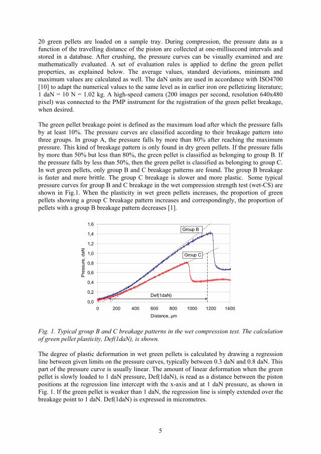
20 green pellets are loaded on a sample tray. During compression, the pressure data as a function of the travelling distance of the piston are collected at one-millisecond intervals and stored in a database. After crushing, the pressure curves can be visually examined and are mathematically evaluated. A set of evaluation rules is applied to define the green pellet properties, as explained below. The average values, standard deviations, minimum and maximum values are calculated as well. The daN units are used in accordance with ISO4700 [10] to adapt the numerical values to the same level as in earlier iron ore pelletizing literature; 1 daN = 10 N = 1.02 kg. A high-speed camera (200 images per second, resolution 640x480 pixel) was connected to the PMP instrument for the registration of the green pellet breakage, when desired.
The green pellet breakage point is defined as the maximum load after which the pressure falls by at least 10%. The pressure curves are classified according to their breakage pattern into three groups. In group A, the pressure falls by more than 80% after reaching the maximum pressure. This kind of breakage pattern is only found in dry green pellets. If the pressure falls by more than 50% but less than 80%, the green pellet is classified as belonging to group B. If the pressure falls by less than 50%, then the green pellet is classified as belonging to group C. In wet green pellets, only group B and C breakage patterns are found. The group B breakage is faster and more brittle. The group C breakage is slower and more plastic. Some typical pressure curves for group B and C breakage in the wet compression strength test (wet-CS) are shown in Fig.1. When the plasticity in wet green pellets increases, the proportion of green pellets showing a group C breakage pattern increases and correspondingly, the proportion of pellets with a group B breakage pattern decreases [1].
0,0
0,2
0,4
0,6
0,8
1,0
1,2
1,4
1,6
0 200 400 600 800 1000 1200 1400Distance, μm
Pre
ssur
e, d
aN
Def(1daN)
Group B
Group C
Fig. 1. Typical group B and C breakage patterns in the wet compression test. The calculation of green pellet plasticity, Def(1daN), is shown.
The degree of plastic deformation in wet green pellets is calculated by drawing a regression line between given limits on the pressure curves, typically between 0.3 daN and 0.8 daN. This part of the pressure curve is usually linear. The amount of linear deformation when the green pellet is slowly loaded to 1 daN pressure, Def(1daN), is read as a distance between the piston positions at the regression line intercept with the x-axis and at 1 daN pressure, as shown in Fig. 1. If the green pellet is weaker than 1 daN, the regression line is simply extended over the breakage point to 1 daN. Def(1daN) is expressed in micrometres.
5
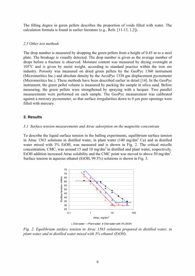
The filling degree in green pellets describes the proportion of voids filled with water. The calculation formula is found in earlier literature (e.g., Refs. [11-13, 1,2]).
2.5 Other test methods
The drop number is measured by dropping the green pellets from a height of 0.45 m to a steel plate. The breakage is visually detected. The drop number is given as the average number of drops before a fracture is observed. Moisture content was measured by drying overnight at 105oC and is given by moist weight, according to standard practice within the iron ore industry. Porosity was measured on dried green pellets by the GeoPyc 1360 instrument (Micromeritics Inc.) and absolute density by the AccuPyc 1330 gas displacement pycnometer (Micromeritics Inc.). These methods have been described earlier in detail [14]. In the GeoPyc instrument, the green pellet volume is measured by packing the sample in silica sand. Before measuring, the green pellets were strengthened by spraying with a lacquer. Two parallel measurements were performed on each sample. The GeoPyc measurement was calibrated against a mercury pycnometer, so that surface irregularities down to 9 μm pore openings were filled with mercury.
3. Results
3.1 Surface tension measurements and Atrac adsorption on the magnetite concentrate
To describe the liquid surface tension in the balling experiments, equilibrium surface tension in Atrac 1563 solutions in distilled water, in plant water (140 mg/dm3 Ca) and in distilled water mixed with 3% EtOH, was measured and is shown in Fig. 2. The critical micelle concentration, CMC, was around 15 and 10 mg/dm3 in distilled and plant water, respectively. EtOH addition increased Atrac solubility and the CMC point was moved to above 50 mg/dm3.Surface tension in aqueous ethanol (EtOH, 99.5%) solutions is shown in Fig. 3.
2530354045505560657075
0,1 1 10 100
Atrac, mg/dm3
Sur
face
tens
ion,
mN
/m
Dist water Plant water Dist water with 3% EtOH
Fig. 2. Equilibrium surface tension in Atrac 1563 solutions prepared in distilled water, in plant water and in distilled water mixed with 3% ethanol (EtOH).
6
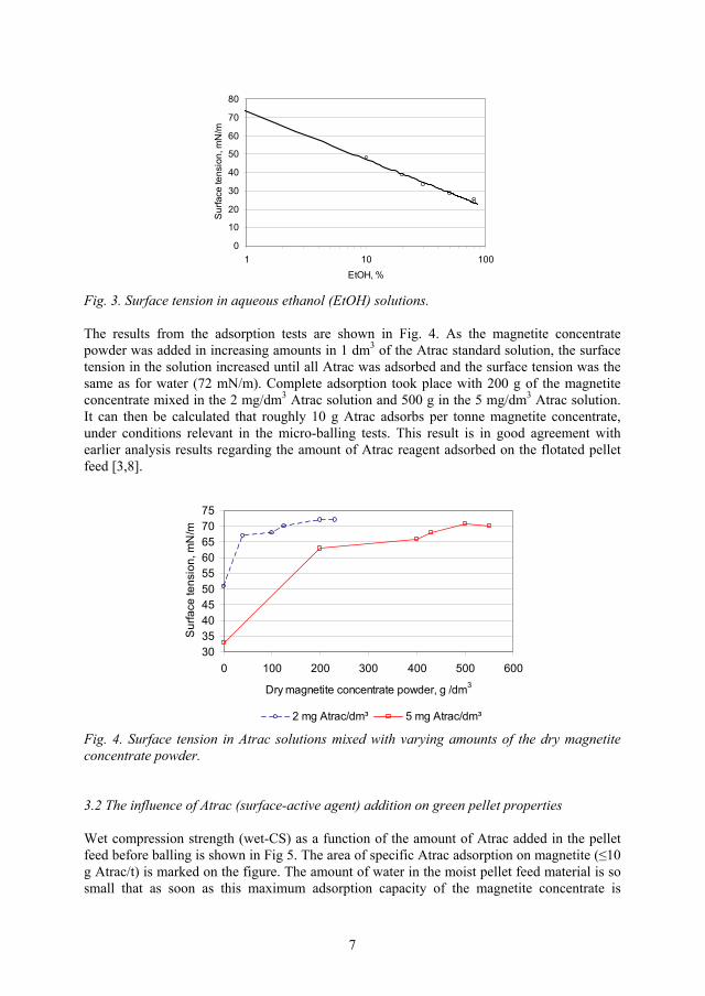
0
10
20
30
40
50
60
70
80
1 10EtOH, %
Sur
face
tens
ion,
mN
/
100
m
Fig. 3. Surface tension in aqueous ethanol (EtOH) solutions.
The results from the adsorption tests are shown in Fig. 4. As the magnetite concentrate powder was added in increasing amounts in 1 dm3 of the Atrac standard solution, the surface tension in the solution increased until all Atrac was adsorbed and the surface tension was the same as for water (72 mN/m). Complete adsorption took place with 200 g of the magnetite concentrate mixed in the 2 mg/dm3 Atrac solution and 500 g in the 5 mg/dm3 Atrac solution. It can then be calculated that roughly 10 g Atrac adsorbs per tonne magnetite concentrate, under conditions relevant in the micro-balling tests. This result is in good agreement with earlier analysis results regarding the amount of Atrac reagent adsorbed on the flotated pellet feed [3,8].
30354045505560657075
0 100 200 300 400 500 600
Dry magnetite concentrate powder, g /dm3
Sur
face
tens
ion,
mN
/m
2 mg Atrac/dm³ 5 mg Atrac/dm³
Fig. 4. Surface tension in Atrac solutions mixed with varying amounts of the dry magnetite concentrate powder.
3.2 The influence of Atrac (surface-active agent) addition on green pellet properties
Wet compression strength (wet-CS) as a function of the amount of Atrac added in the pellet feed before balling is shown in Fig 5. The area of specific Atrac adsorption on magnetite ( 10g Atrac/t) is marked on the figure. The amount of water in the moist pellet feed material is so small that as soon as this maximum adsorption capacity of the magnetite concentrate is
7
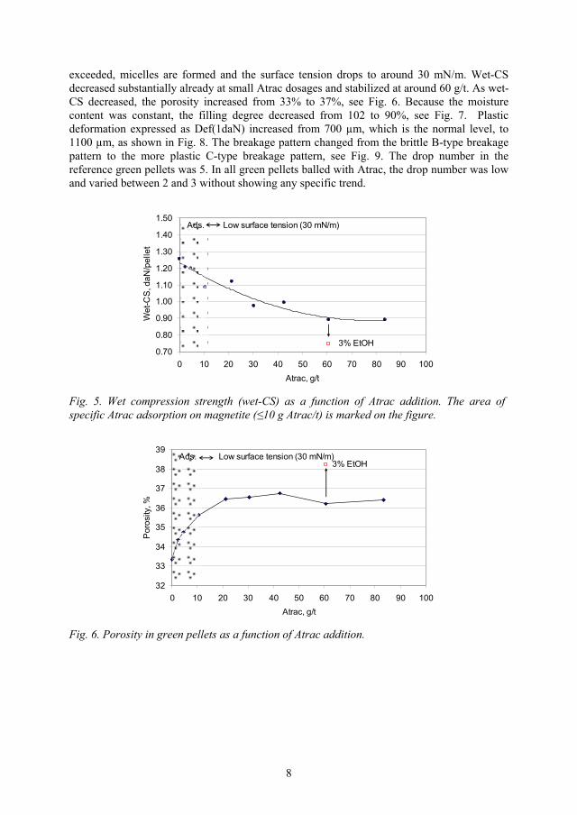
exceeded, micelles are formed and the surface tension drops to around 30 mN/m. Wet-CS decreased substantially already at small Atrac dosages and stabilized at around 60 g/t. As wet-CS decreased, the porosity increased from 33% to 37%, see Fig. 6. Because the moisture content was constant, the filling degree decreased from 102 to 90%, see Fig. 7. Plastic deformation expressed as Def(1daN) increased from 700 μm, which is the normal level, to 1100 μm, as shown in Fig. 8. The breakage pattern changed from the brittle B-type breakage pattern to the more plastic C-type breakage pattern, see Fig. 9. The drop number in the reference green pellets was 5. In all green pellets balled with Atrac, the drop number was low and varied between 2 and 3 without showing any specific trend.
0.70
0.80
0.90
1.00
1.10
1.20
1.30
1.40
1.50
0 10 20 30 40 50 60 70 80 90 100Atrac, g/t
Wet
-CS
, daN
/pel
let
Ads. Low surface tension (30 mN/m)
3% EtOH
Fig. 5. Wet compression strength (wet-CS) as a function of Atrac addition. The area of specific Atrac adsorption on magnetite ( 10 g Atrac/t) is marked on the figure.
32
33
34
35
36
37
38
39
0 10 20 30 40 50 60 70 80 90 100Atrac, g/t
Por
osity
, %
Ads. Low surface tension (30 mN/m) 3% EtOH
Fig. 6. Porosity in green pellets as a function of Atrac addition.
8
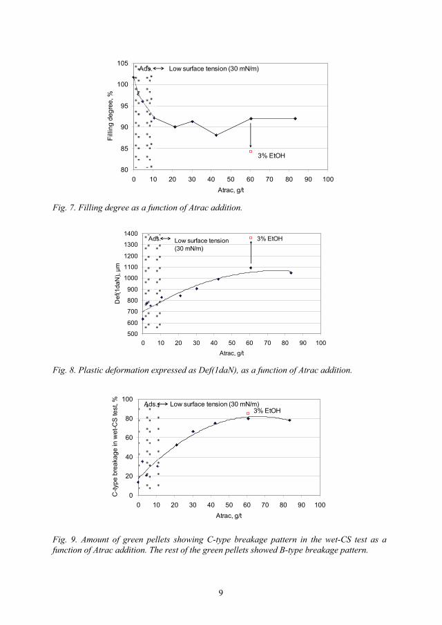
80
85
90
95
100
105
0 10 20 30 40 50 60 70 80 90 100Atrac, g/t
Filli
ng d
egre
e, %
Ads. Low surface tension (30 mN/m)
3% EtOH
Fig. 7. Filling degree as a function of Atrac addition.
500
600
700
800
900
1000
1100
1200
1300
1400
0 10 20 30 40 50 60 70 80 90 100Atrac, g/t
Def
(1da
N), μm
Ads. Low surface tension (30 mN/m)
3% EtOH
Fig. 8. Plastic deformation expressed as Def(1daN), as a function of Atrac addition.
0
20
40
60
80
100
0 10 20 30 40 50 60 70 80 90 100Atrac, g/t
C-ty
pe b
reak
age
in w
et-C
S te
st, % Ads. Low surface tension (30 mN/m)
3% EtOH
Fig. 9. Amount of green pellets showing C-type breakage pattern in the wet-CS test as a function of Atrac addition. The rest of the green pellets showed B-type breakage pattern.
9
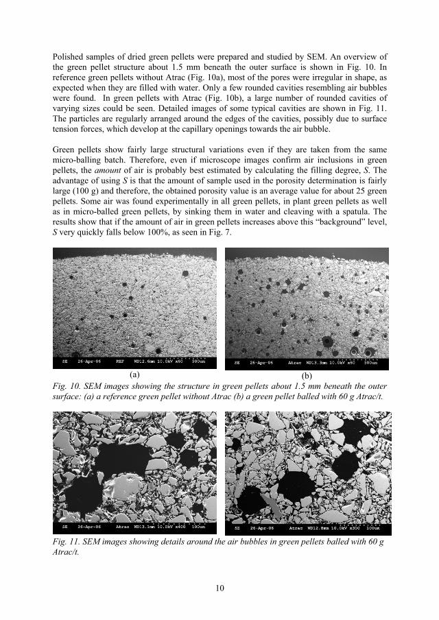
Polished samples of dried green pellets were prepared and studied by SEM. An overview of the green pellet structure about 1.5 mm beneath the outer surface is shown in Fig. 10. In reference green pellets without Atrac (Fig. 10a), most of the pores were irregular in shape, as expected when they are filled with water. Only a few rounded cavities resembling air bubbles were found. In green pellets with Atrac (Fig. 10b), a large number of rounded cavities of varying sizes could be seen. Detailed images of some typical cavities are shown in Fig. 11. The particles are regularly arranged around the edges of the cavities, possibly due to surface tension forces, which develop at the capillary openings towards the air bubble.
Green pellets show fairly large structural variations even if they are taken from the same micro-balling batch. Therefore, even if microscope images confirm air inclusions in green pellets, the amount of air is probably best estimated by calculating the filling degree, S. The advantage of using S is that the amount of sample used in the porosity determination is fairly large (100 g) and therefore, the obtained porosity value is an average value for about 25 green pellets. Some air was found experimentally in all green pellets, in plant green pellets as well as in micro-balled green pellets, by sinking them in water and cleaving with a spatula. The results show that if the amount of air in green pellets increases above this “background” level, S very quickly falls below 100%, as seen in Fig. 7.
(a) (b)Fig. 10. SEM images showing the structure in green pellets about 1.5 mm beneath the outer surface: (a) a reference green pellet without Atrac (b) a green pellet balled with 60 g Atrac/t.
Fig. 11. SEM images showing details around the air bubbles in green pellets balled with 60 g Atrac/t.
10

Some typical pressure curves collected with the PMP instrument from wet-CS measurement are shown in Fig 12. The pressure curves show that with Atrac added to the pellet feed the pressure curves became more rounded and the breakage event was slower. The compression of wet green pellets was also filmed with the high-speed camera. The camera images showed that in green pellets containing Atrac, the breakage often seemed to start inside the green pellets, initially causing several simultaneous cracks. As the compression advanced further, the small cracks merged together to one single crack. High-speed camera images for a typical reference green pellet and for a green pellet balled with Atrac and showing the multi-breakage behaviour are shown in Fig. 13.
0,2
0,4
0,6
0,8
1,0
1,2
1,4
1,6
700 800 900 1000 1100 1200 1300 1400 1500Distance, μm
Pre
ssur
e, d
aN
Reference
60 g Atrac/t
Fig. 12. Some typical pressure curves for wet green pellets (wet-CS test) without Atrac (reference) and with 60 g Atrac/t.
(a) (b)Fig 13. High-speed camera images showing typical cracks in wet green pellets: (a) a reference green pellet without Atrac (b) a green pellet balled with 60 g Atrac/t showing several simultaneous cracks.
Dry compression strength, dry-CS, as a function of Atrac addition is shown in Fig. 14. Dry-CS decreased from 5.8 to 4.0 daN/pellet with 10 g Atrac/t and then stabilized on this level. The decrease in the numerical value for dry-CS was smaller than expected from the high-speed camera images. Some images of typical breakage sequences are shown in Fig. 15. Green pellets containing Atrac showed more multi-breakage sequences. Not only one, but several, cleavage planes were formed and the green pellets were broken to crumbs instead of two or three larger pieces. More fines appeared to loosen at the moment of crack formation in
11
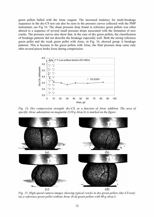
green pellets balled with the Atrac reagent. The increased tendency for multi-breakage sequences in the dry-CS test can also be seen in the pressure curves collected with the PMP instrument, see Fig 16. The sharp pressure drop found in reference green pellets was often altered to a sequence of several small pressure drops associated with the formation of new cracks. The pressure curves also show that, in the case of dry green pellets, the classification of breakage patterns did not describe the breakage especially well. Both the strong reference green pellet and the weak green pellet with Atrac, in Fig. 16, showed group A breakage patterns. This is because in the green pellets with Atrac, the final pressure drop came only after several pieces broke loose during compression.
3.0
3.5
4.0
4.5
5.0
5.5
6.0
0 10 20 30 40 50 60 70 80 90 100Atrac, g/t
Dry
-CS
, daN
/pel
let
Ads. Low surface tension (30 mN/m)
3% EtOH
Fig. 14. Dry compression strength, dry-CS, as a function of Atrac addition. The area of specific Atrac adsorption on magnetite ( 10 g Atrac/t) is marked on the figure.
(a) (b)
(c) (d)Fig. 15. High-speed camera images showing typical cracks in dry green pellets (dry-CS test): (a) a reference green pellet without Atrac (b-d) green pellets with 60 g Atrac/t.
12
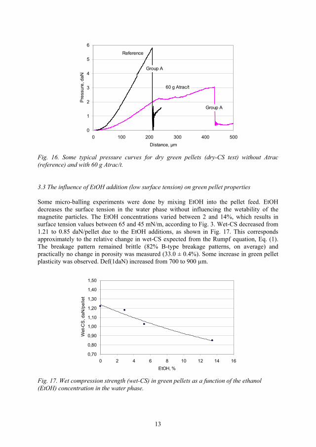
0
1
2
3
4
5
6
0 100 200 300 400 500Distance, μm
Pre
ssur
e, d
aN
Reference
60 g Atrac/t
Group A
Group A
Fig. 16. Some typical pressure curves for dry green pellets (dry-CS test) without Atrac (reference) and with 60 g Atrac/t.
3.3 The influence of EtOH addition (low surface tension) on green pellet properties
Some micro-balling experiments were done by mixing EtOH into the pellet feed. EtOH decreases the surface tension in the water phase without influencing the wetability of the magnetite particles. The EtOH concentrations varied between 2 and 14%, which results in surface tension values between 65 and 45 mN/m, according to Fig. 3. Wet-CS decreased from 1.21 to 0.85 daN/pellet due to the EtOH additions, as shown in Fig. 17. This corresponds approximately to the relative change in wet-CS expected from the Rumpf equation, Eq. (1). The breakage pattern remained brittle (82% B-type breakage patterns, on average) and practically no change in porosity was measured (33.0 ± 0.4%). Some increase in green pellet plasticity was observed. Def(1daN) increased from 700 to 900 μm.
0,70
0,80
0,90
1,00
1,10
1,20
1,30
1,40
1,50
0 2 4 6 8 10 12 14 16EtOH, %
Wet
-CS
, daN
/pel
let
Fig. 17. Wet compression strength (wet-CS) in green pellets as a function of the ethanol (EtOH) concentration in the water phase.
13

Some micro-balling experiments were also done by mixing both EtOH (3%) and Atrac (60 g/t) simultaneously into the magnetite concentrate before balling. The measuring points are shown in earlier figures, Fig. 5 to 9. The addition of EtOH lowered the wet-CS substantially from the value obtained with Atrac only (from 0.90 to 0.75 daN/pellet). The addition of EtOH also further increased the porosity and plasticity – all signs of increased amounts of entrapped air in the green pellets. Probably, EtOH either behaves as a frother or by some means stabilizes the air bubbles adhering to magnetite surfaces.
4. Discussion
When the surface-active agent, Atrac, was mixed with the magnetite concentrate, an increasing amount of air bubbles became so strongly attached to the particle surfaces that they could not be removed from green pellets during compaction by balling. The best way to detect that Atrac is carried over to the pelletizing plant is to measure the green pellet porosity and moisture content and calculate the filling degree.
The main increase in porosity took place at Atrac dosages below 10 g/t, which is roughly the maximum adsorption capacity for the magnetite concentrate, but wet-CS continued to decrease and Def(1daN) continued to increase, even at larger Atrac dosages. This decrease in wet-CS can hardly be explained by a decrease in the capillary forces, because the amount of water is so small that the CMC point is passed as soon as the specific adsorption on magnetite is completed. Therefore, at Atrac dosages above 10 g/t, the surface tension becomes low and constant and micelles are formed. If the micelles had adsorbed on magnetite, a further increase in porosity would have been expected. It could be that the micelles behave as a lubricant, increasing the green pellet plasticity and decreasing the green pellet wet strength. Wet-CS is also largely dependent on the viscosity developed in the bentonite suspension and its rheological behaviour in the presence of large amounts of surface-active agents is not known.
An Atrac addition of 10 g/t caused a 2% increase in green pellet porosity. Earlier data with similar raw materials [2] showed that magnetite pellet concentrates with varying particle size distributions demand different moisture contents in balling to ensure an acceptable level of plasticity in green pellets. In the materials studied, a 2% difference in porosity due to the difference in the moisture content was measured. In spite of this difference in porosity, the green pellets were equally strong in wet-CS. Therefore, the primary problem with Atrac adsorption on magnetite is not the increase in porosity, as such, but the fact that the increase in porosity takes place via air bubbles, which weaken the overall mechanical structure of the green pellets. The air bubbles probably weaken the mechanical structure of sintered pellets, as well.
In earlier textbooks [11-13], the calculation of the filling degree is used to denote the difference between the funicular, capillary and droplet states. In industrial balling of iron ore green pellets, the balling conditions are such that there is always a slight surplus of water. When the moisture content (within the area of reasonable ballability) increases, the particles in green pellets are further “diluted” with water, the pores become larger and the porosity increases, but the filling degree remains constant [2]. Therefore, under normal balling conditions, the filling degree does not describe the green pellet properties. Depending on the moisture content, large variations in green pellet plasticity and ballability take place. When the green pellets contain air bubbles, the filling degree drops substantially, but the green
14

pellets are still in the capillary state because the air does not fill the capillaries but the air bubbles behave like large particles. If balling were done at such low moisture content, that partial binding with liquid bridges would take place, the green pellets would be in true funicular state and very weak. In full-scale balling this is not likely to happen, because it would result in an increase in the recycling loads in the balling circuits and would be compensated by adding more water. It should also be noted that although the filling degree in iron ore green pellets containing air bubbles is low, there still is a partial surplus of water on the outer surface of the green pellets. The state of liquid saturation is between the capillary and droplet states, as described earlier [2]. The local surplus of water can be seen as a wet “shine” on the green pellets and is considered a prerequisite for the green pellets to grow.
Air bubbles in green pellets also pose a dilemma for the agglomeration theory to describe the development of the capillary forces around the air bubbles. Normally, when the pores in green pellets are completely filled with water, capillary forces only develop at the green pellet outer surface. In the case of air bubbles enclosed in the green pellet structure, capillary forces probably also develop in the capillary openings facing towards the air bubbles, inside the green pellets.
The discussion above shows that the calculation of filling degree is essential for the evaluation of iron ore green pellet properties, although for a different reason than shown in earlier textbooks. The calculation of the filling degree is very sensitive to changes in porosity. Obviously, high accuracy, or at least high repeatability, in the porosity measurement is essential. The development work done at LKAB using the GeoPyc instrument [14] has resulted in stable and repeatable porosity values.
Balling with water/ethanol mixtures also decreased the wet-CS values in green pellets, but ethanol had no influence on porosity. The decrease in wet-CS followed approximately the Rumpf equation (Eq. 1) and could, therefore, be explained by a decrease in the capillary force. However, the same applies for ethanol as for the surface-active agent: the rheological behaviour of bentonite suspensions in the presence of ethanol should be solved before definite conclusions can be drawn. When small amounts of ethanol were added together with the Atrac reagent, the amount of air bubbles enclosed in the green pellet structure increased even further. Ethanol probably behaved like a frother. This suggests that if alcohols are used as model substances in agglomeration experiments to create low surface tension in the water phase, the pellet feed should be free of surface-active agents and the porosity in green pellets should be carefully analyzed. Small amounts of lubricating oils, humic acids and other substances of surface-active nature often occur in plant water.
The behaviour of green pellets with enclosed air bubbles should also be considered under process conditions in the pelletizing machine. In the drying zones, the green pellets are dried by drawing hot air (150 to 450oC) through the green pellet bed. During drying, an equilibrium temperature of around 50oC in the green pellet bed is established. The increase in temperature makes the air bubbles expand. This, in combination with the lower dry-CS values, explains the increased generation of fines, crumb and dust at times observed when pelletizing flotated pellet feeds.
Atrac is highly selective for apatite. With Atrac adsorption by 10 g per tonne magnetite concentrate, the adsorption on apatite would be around 500 g per tonne apatite mineral (Atrac dosage of 50 g/t in flotation and 1% P in the flotation feed). A certain over-dosage of Atrac is needed to assure high enough P-reduction. Increased Atrac over-dosage can be expected to
15
lead to increased specific adsorption on the magnetite surfaces. Therefore, to minimize the draw-backs of Atrac carried over to the pelletizing plant, proper control over the flotation process is essential. This also covers a strict control to hinder the apatite froth from being carried over to the pellet feed.
In the flotation process the contact area between particles and air bubbles is maximized in order to float the apatite mineral. Thus, the conditions are favourable for air bubbles to adsorb on magnetite particles, as well, even if the amount of air bubbles would not be high enough to float the magnetite. In the micro-balling experiments, the air bubbles were generated either during mixing or during spraying of the Atrac solution into the mixing vessel. Therefore, the number of attached air bubbles and their size distribution could differ in the laboratory balling experiments compared to production plant conditions. In spite of this difference, samples collected from the pelletizing plant have shown quite similar changes in porosity, as was seen in the micro-balled green pellets.
5. Conclusions
1. When applied to practical process control, the main conclusion from this work is that the best way to detect that Atrac is carried over to the pelletizing plant and causes problems in balling is to measure the filling degree. The corrective process control measure would be to revise the status of the flotation process. Also, a slight decrease in the moisture content might reduce the drawbacks of highly plastic green pellets.
2. Calculating the filling degree is essential for the evaluation of green pellet properties, although for a different reason than shown in earlier textbooks. Under normal balling conditions for iron ore green pellets, the filling degree is above 100% and does not give any information about agglomerate behaviour. This is because balling is a self-regulating system and an increase in the moisture content is compensated by an increase in porosity, which results in a constant filling degree. In the presence of air bubbles, however, the filling degree drops well below 100%. This low filling degree is not a sign of the agglomerate being in the funicular state, because the air in green pellets is embedded as air bubbles, which behave like large, plastic particles.
3. The decrease in iron ore green pellet wet strength in the presence of surface-active agents is not fully described by using surface tension and contact angle as variables in mathematical expressions. The main problem is not the contact angle between the particle surfaces and the water phase, but arises from the strong attachment between air bubbles and the hydrophobic particle surfaces.
Acknowledgements
This work has been performed within the Agricola Research Centre (ARC) at Luleå University of Technology, Sweden. ARC is funded by the Swedish Foundation for Strategic Research, LKAB and Boliden Mineral AB.
16

References
1. S.P.E. Forsmo, A.J. Apelqvist, B.M.T. Björkman, P-O. Samskog, Binding mechanisms in wet iron ore green pellets with a bentonite binder, Powder Technol. 169 (2006) 147-158.
2. S.P.E. Forsmo, P-O. Samskog, B.M.T. Björkman, A study on plasticity and compression strength in wet iron ore green pellets related to real process variations in raw material fineness, Submitted to Powder Technol. POWTEC-D-06-00143.
3. J-O. Gustafsson, G. Adolfsson, Adsorption of carboxylate collectors on magnetite and their influence on the pelletizing process, XX International Mineral Processing Congress, Aachen, Sep. 21-26, 1997, 377-390.
4. H. Rumpf, in: W. A. Knepper (Ed.), The Strength of Granules and Agglomerates, AIME, Agglomeration, Interscience, New-York, 1962, pp. 379-418.
5. M. Lazghab, K. Saleh, I. Pezron, P. Guidon, L. Komunjer, Wettability assessment of finely divided solids, Powder Technol. 157 (2005) 79-91.
6. S.M. Iveson, J.D. Litster, K. Hapgood, B.J. Ennis. Nucleation, growth and breakage phenomena in agitated wet granulation processes: a review, Powder Technol. 117 (2001) 3-39.
7. P.C. Knight, Structuring agglomerated products for improved performance, Powder Technol. 119 (2001) 14-25.
8. LKAB internal report. Unpublished data.
9. J. Svensson, Bestämning av specifika ytan på kross-och malgods enligt permeabilitetsmetoden, Jernkontorets Ann., Stockholm 133 (1949) 33-86 (in Swedish).
10. International Standard ISO4700:1996(E). Iron ore pellets – determination of crushing strength, 1996.
11. D.F. Ball, J. Dartnell, J. Davison, A. Grieve, R. Wild, Agglomeration in iron ores, Heinemann Educational Books Ltd., London, 1973.
12. K. Meyer, Pelletizing of iron ores, Springer-Verlag, Berlin, 1980.
13. W. Pietsch, Size Enlargement by Agglomeration, John Wiley & Sons, Chichester, England, 1991.
14. S.P.E. Forsmo, J.P. Vuori, The determination of porosity in iron ore green pellets by packing in silica sand, Powder Technol. 159 (2005) 71-77.
17

ARTICLE VI
Influence of the olivine additive fineness on the oxidation of magnetite pellets
S.P.E. Forsmo, A. Hägglund
International Journal of Mineral Processing 70 (2003) 109-122.
Reprinted with permission from Elsevier. Copyright 2003.
VI

Influence of the olivine additive fineness on the
oxidation of magnetite pellets
S.P.E. Forsmoa,b,*, A. Hagglunda
aLuossavaara–Kiirunavaara AB (LKAB), R&D, S-98381 Malmberget, SwedenbAgricola Research Centre, Lulea University of Technology, S-97187 Lulea, Sweden
Received 4 October 2002; accepted 8 November 2002
Abstract
Olivine is used as an additive in Luossavaara–Kiirunavaara AB (LKAB) blast furnace pellets. The
LKAB iron ore is magnetite which oxidizes to hematite during the sintering process. Olivine retards the
oxidation of magnetite pellets if the threshold temperature of magnesioferrite formation is exceeded.
In this study, we have developed a thermogravimetric measuring method to study the relationship
between the olivine reactivity in green pellets and the olivine fineness. A less reactive olivinemakes the
pelletizing process more tolerant of excessively high temperatures in the green pellets during oxidation.
The reactivity of olivine decreases when the amount of fine tail in olivine is decreased. The top
size is limited by balling. Grinding tests in pilot scale show that if the olivine additive is ground in
closed circuit with a ball mill keeping good control over the top size, the olivine fineness can be
appreciably decreased without disturbing balling. The olivine reactivity can be decreased by 40%
compared to the reference olivine in the production plant. Also, savings can be made on both the
grinding energy and grinding media consumption. The results in both pilot scale and full production
scale show that better oxidation in the grate due to a coarser olivine additive improves the low
temperature reduction strength (LTD, ISO 13930) in pellets.
The measuring method developed for the olivine reactivity enabled evaluation of different
particle-sizing methods for olivine characterisation. The screening size fraction %� 45 Am showed a
good correlation to olivine reactivity in green pellets within a very large measuring range. The
correlation of laser diffraction analysis to the olivine reactivity showed, however, that the laser
diffraction measuring method is affected too much by variations in the large particles.
D 2003 Elsevier Science B.V. All rights reserved.
Keywords: magnetite; hematite; olivine; oxidation; dissociation; agglomeration
0301-7516/03/$ - see front matter D 2003 Elsevier Science B.V. All rights reserved.
doi:10.1016/S0301-7516(02)00155-2
* Corresponding author. Fax: +46-970-30617.
E-mail address: [email protected] (S.P.E. Forsmo).
www.elsevier.com/locate/ijminpro
Int. J. Miner. Process. 70 (2003) 109–122
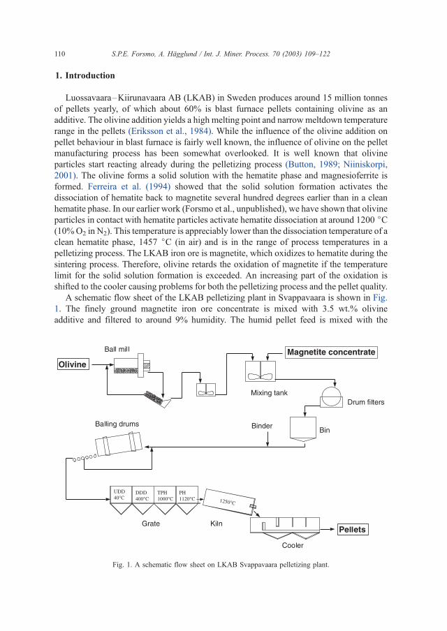
1. Introduction
Luossavaara–Kiirunavaara AB (LKAB) in Sweden produces around 15 million tonnes
of pellets yearly, of which about 60% is blast furnace pellets containing olivine as an
additive. The olivine addition yields a high melting point and narrow meltdown temperature
range in the pellets (Eriksson et al., 1984). While the influence of the olivine addition on
pellet behaviour in blast furnace is fairly well known, the influence of olivine on the pellet
manufacturing process has been somewhat overlooked. It is well known that olivine
particles start reacting already during the pelletizing process (Button, 1989; Niiniskorpi,
2001). The olivine forms a solid solution with the hematite phase and magnesioferrite is
formed. Ferreira et al. (1994) showed that the solid solution formation activates the
dissociation of hematite back to magnetite several hundred degrees earlier than in a clean
hematite phase. In our earlier work (Forsmo et al., unpublished), we have shown that olivine
particles in contact with hematite particles activate hematite dissociation at around 1200 jC(10%O2 in N2). This temperature is appreciably lower than the dissociation temperature of a
clean hematite phase, 1457 jC (in air) and is in the range of process temperatures in a
pelletizing process. The LKAB iron ore is magnetite, which oxidizes to hematite during the
sintering process. Therefore, olivine retards the oxidation of magnetite if the temperature
limit for the solid solution formation is exceeded. An increasing part of the oxidation is
shifted to the cooler causing problems for both the pelletizing process and the pellet quality.
A schematic flow sheet of the LKAB pelletizing plant in Svappavaara is shown in Fig.
1. The finely ground magnetite iron ore concentrate is mixed with 3.5 wt.% olivine
additive and filtered to around 9% humidity. The humid pellet feed is mixed with the
Fig. 1. A schematic flow sheet on LKAB Svappavaara pelletizing plant.
S.P.E. Forsmo, A. Hagglund / Int. J. Miner. Process. 70 (2003) 109–122110

bentonite binder and balled to green pellets of an average size of around 12 mm. The
green pellets are heat-treated in the grate-kiln pelletizing process. First, the green pellets
are oxidised in a static bed in the grate, at gas temperatures around 1000 to 1120 jC.Then, the pellets are loaded to the kiln where final sintering takes place at about 1250 jC.The pellets are cooled in the rotary cooler. To avoid rest oxidation in the cooler, the pellet
oxidation degree after the grate should be as high as possible. This is favourable for other
reasons as well.
In an industrial pelletizing process, the pellet temperature is raised very rapidly, and
conditions in the system are far from thermodynamically balanced. In order to achieve a
high degree of oxidation in pellets during heat treatment in the grate, the oxidation needs to
advance as far as possible before the magnesioferrite formation starts. The magnesioferrite
formation rate is not only influenced by the pellet temperature, but also by the available
surface area of the olivine particles. This, in turn, depends on the amount of olivine in the
pellets and on the fineness of the olivine particles. The total amount of olivine is adjusted to
gain desired pellet properties in the blast furnace and is therefore fixed. The olivine fineness
can, however, be optimised so as to reach the lowest possible reactivity during the
pelletizing process. In our earlier pilot-scale studies (Samskog et al., 2002), we have
shown that the use of coarser olivine greatly improves the pellet mechanical properties
during low temperature reduction (LTD, ISO 13930), see Fig. 2. This is thought to be due to
better oxidation in the grate.
The aim of the present study was to determine how much the olivine reactivity can be
retarded by decreasing the amount of small particles in olivine. The limiting factor for
olivine fineness is that the coarser olivine should not weaken the green pellets. Therefore,
the absolute top size was restricted to 200 Am. Also, the amount of + 100 Am particles
Fig. 2. Low temperature reduction strength (LTD) in magnetite pellets indurated in pot-furnace according to
Samskog et al. (2002). The pellets contained 0.5% bentonite binder and 3.5% olivine with three different finesses.
The induration program was not optimised for the magnetite feed material.
S.P.E. Forsmo, A. Hagglund / Int. J. Miner. Process. 70 (2003) 109–122 111
should not increase significantly after the olivine is mixed with the magnetite concentrate.
Alternative grinding circuit layouts to produce olivine with narrow particle size distribu-
tion were studied in pilot scale. A thermogravimetric measuring method was developed to
determine the reactivity of olivine in the green pellets. The olivine products were then
characterised according to particle size and reactivity.
We also studied how different particle-sizing methods correlate with the olivine reactivity
in the green pellet. This information is necessary for achieving good control over the olivine
grinding circuit in the production scale. Finally, the olivine fineness at LKAB’s Svappavaara
plant was decreased to study the resulting effect in full production scale.
2. Experimental
2.1. Materials
Olivine is a generic term for a group of minerals consisting of solid solutions of
forsterite (2MgO�SiO2) and fayalite (2FeO�SiO2). This study was done with olivine from
Aheim in Norway. The Aheim olivine is of the forsterite type, with a relatively high
magnesium content, typically 48% MgO, 42% SiO2 and 5% Fe. The olivine raw material
was crushed to a fineness of 95%� 12 mm (20%� 180 Am, 50%� 1 mm) before the
pilot-scale grinding tests.
As a reference, olivine samples taken from the LKAB Svappavaara production plant
were used. These olivine samples also contained minor amounts of limestone.
The magnetite concentrate used in this study is from LKAB’s Svappavaara concen-
trating plant and typically contains 71.0% Fe. The particle size of Svappavaara magnetite
pellet concentrate (SPC) is typically 76%� 45 Am and 98%� 125 Am (by screening).
2.2. Pilot plant grinding tests
Several different grinding circuit layouts were run at the LKAB pilot plant. The test runs
were divided into two main groups according to the type of grinding mill used: rod mill
grinding (RM) and ball mill grinding (BG). Within each main group, several test runs with
different layouts and somewhat different settings were run. These runs are numbered
consecutively (RM1, RM2, etc.). Two of the ball mill ground products were further
deslimed (DS). Also, the slime products (SLIME) were characterised for their fineness.
2.2.1. Rod mill grinding tests
Narrow particle-size distribution for olivine was one of the targets of this study;
therefore, rod mill grinding was studied as one alternative. The question was whether the
rod mill grinding done in one stage could meet the given restrictions for the top size.
The rod mill was run both in open circuit followed by scalping (RM1) and in closed
circuit with screen (RM2 and RM3). One test (RM4) was run with the rod mill in closed
circuit with a Floatex density separator.
The rod mill used was of trunnion overflow type, diameter 1.0 m and length 1.5 m. A
trommel screen with 3-mm screen opening was used at the mill discharge. The rod mill
S.P.E. Forsmo, A. Hagglund / Int. J. Miner. Process. 70 (2003) 109–122112
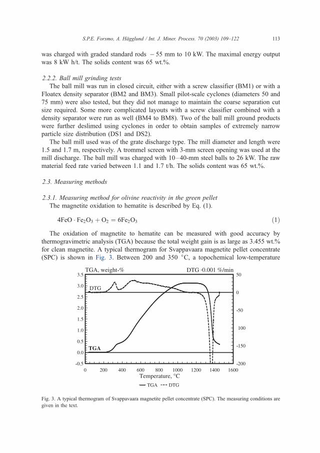
was charged with graded standard rods � 55 mm to 10 kW. The maximal energy output
was 8 kW h/t. The solids content was 65 wt.%.
2.2.2. Ball mill grinding tests
The ball mill was run in closed circuit, either with a screw classifier (BM1) or with a
Floatex density separator (BM2 and BM3). Small pilot-scale cyclones (diameters 50 and
75 mm) were also tested, but they did not manage to maintain the coarse separation cut
size required. Some more complicated layouts with a screw classifier combined with a
density separator were run as well (BM4 to BM8). Two of the ball mill ground products
were further deslimed using cyclones in order to obtain samples of extremely narrow
particle size distribution (DS1 and DS2).
The ball mill used was of the grate discharge type. The mill diameter and length were
1.5 and 1.7 m, respectively. A trommel screen with 3-mm screen opening was used at the
mill discharge. The ball mill was charged with 10–40-mm steel balls to 26 kW. The raw
material feed rate varied between 1.1 and 1.7 t/h. The solids content was 65 wt.%.
2.3. Measuring methods
2.3.1. Measuring method for olivine reactivity in the green pellet
The magnetite oxidation to hematite is described by Eq. (1).
4FeO � Fe2O3 þ O2 ¼ 6Fe2O3 ð1ÞThe oxidation of magnetite to hematite can be measured with good accuracy by
thermogravimetric analysis (TGA) because the total weight gain is as large as 3.455 wt.%
for clean magnetite. A typical thermogram for Svappavaara magnetite pellet concentrate
(SPC) is shown in Fig. 3. Between 200 and 350 jC, a topochemical low-temperature
Fig. 3. A typical thermogram of Svappavaara magnetite pellet concentrate (SPC). The measuring conditions are
given in the text.
S.P.E. Forsmo, A. Hagglund / Int. J. Miner. Process. 70 (2003) 109–122 113
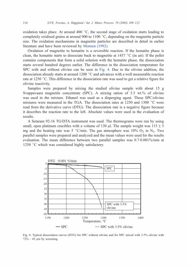
oxidation takes place. At around 400 jC, the second stage of oxidation starts leading to
completely oxidised grains at around 900 to 1100 jC, depending on the magnetite particle
size. The oxidation mechanisms in magnetite particles are described in detail in earlier
literature and have been reviewed by Monsen (1992).
Oxidation of magnetite to hematite is a reversible reaction. If the hematite phase is
clean, the hematite starts to dissociate back to magnetite at 1457 jC (in air). If the pellet
contains components that form a solid solution with the hematite phase, the dissociation
starts several hundred degrees earlier. The difference in the dissociation temperature for
SPC with and without olivine can be seen in Fig. 4. Due to the olivine addition, the
dissociation already starts at around 1200 jC and advances with a well measurable reaction
rate at 1250 jC. This difference in the dissociation rate was used to get a relative figure forolivine reactivity.
Samples were prepared by mixing the studied olivine sample with about 15 g
Svappavaara magnetite concentrate (SPC). A mixing ration of 3.5 wt.% of olivine
was used in the mixture. Ethanol was used as a disperging agent. These SPC/olivine
mixtures were measured in the TGA. The dissociation rates at 1250 and 1300 jC were
read from the derivative curve (DTG). The dissociation rate is a negative figure because
it describes the reaction rate to the left. Absolute values were used in the evaluation of
results.
A Setaram 92-16 TG/DTA instrument was used. The thermograms were run by using
small, open platinum crucibles with a volume of 130 Al. The sample weight was 115F 5
mg and the heating rate was 5 jC/min. The gas atmosphere was 10% O2 in N2. Two
parallel samples were prepared and analyzed and the mean values were used for the results
evaluation. The mean difference between two parallel samples was 0.7�0.001%/min at
1250 jC which was considered highly satisfactory.
.
Fig. 4. Typical dissociation curves (DTG) for SPC without olivine and for SPC mixed with 3.5% olivine with
72%� 45 Am by screening.
S.P.E. Forsmo, A. Hagglund / Int. J. Miner. Process. 70 (2003) 109–122114

2.3.2. Particle size measuring methods
Three different particle-sizing methods were used: screening, laser diffraction and KTH
surface. For screening, Endecott screens were used. The � 45 Am fraction was wet-
screened.
The laser diffraction analysis was done using Malvern Mastersizer S. The measuring
principle of the laser diffraction measuring method is explained in the international
standard, ISO 13320 (1999). Laser diffraction measures a volume distribution of round
spheres. The largest cross-sectional measure of the particles defines the diameter of the
spheres. Dry measurement with 100-g samples was used. The measurement range was 0.5
to 879 Am. The D10, D50 and D90 values were used for the evaluation. D10 means that 10
vol.% of all particles are below the given particle size in micrometers.
The third analysis method used for particle sizing is KTH surface. In the KTH-surface
method, the particle surface area is calculated from gas permeability through a packed bed
of particles (Svensson, 1949). The measuring range starts from around 3000 cm2/cm3.
3. Results and discussion
3.1. Evaluation of different grinding circuit layouts for olivine
The particle sizing and reactivity data are summarised in Table 1. Screen analysis
results of some typical samples are shown in Fig. 5.
The curve RM2 in Fig. 5 shows that rod mill grinding resulted, as expected, in low
amounts of fine tail (21–26%� 45 Am by screening), but the requirement of limited
increase in + 100 Am particles in the pellet feed after the olivine addition could not be
fulfilled. Almost one-half of the olivine particles after rod mill grinding were larger than
100 Am.
Similar problems with top size were encountered when running a screw classifier in
closed circuit with a ball mill (see curve marked BM1 in Fig. 5). On the other hand, ball
mill grinding in closed circuit with a Floatex density separator, resulted in good top-size
control and a fine tail of 40–42%� 45 Am by screening, as shown by the curve marked
BM2 in Fig. 5. The more complicated ball mill layouts using a screw classifier in
combination with a density separator (samples BM4 to BM8 in Table 1), created just as
much fines as the simpler layout (BM2).
Olivine with 65%� 45 Am (by screening) from the Svappavaara production plant is
shown as a reference in Fig. 5. In Svappavaara, the olivine control value was decreased
from 72% to 65%� 45 Am (SVP1 and SVP2 in Table 1). No problems with green pellet
strength were experienced. The coarser olivine resulted in a more robust pelletizing
process, less liable to disturbances in the magnetite oxidation. As an indication of better
and more consistent oxidation in the grate, the pellet low temperature reduction strength
(LTD, ISO 13930) measured on samples taken at the pelletizing plant showed an increase
from 92F 2(1r)% + 6.3 mm to 95F 1(1r)% + 6.3 mm due to the use of coarser olivine.
The pilot-scale grinding tests show that by closed-circuit grinding in a ball mill while
maintaining good control over the top size, the olivine control value could probably be
drawn down near to 40%� 45 Am without problems in balling.
S.P.E. Forsmo, A. Hagglund / Int. J. Miner. Process. 70 (2003) 109–122 115
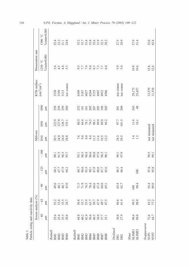
Table
1
Particlesizingandreactivitydata
Screenanalysis(%
)Malvern
KTH
surface
Dissociationrate
�45
Am�63
Am�90
Am�125
Am�180
AmD10
AmD50
AmD90
Am
(cm
2/cm
3)
1250jC
%/m
in*0.001
1300jC
%/m
in*0.001
Rodmill
RM1
25.6
35.2
49.6
68.5
90.1
20.5
122.9
258
3330
5.6
25.4
RM2
25.4
33.6
48.1
67.7
91.5
24.9
127.9
259
3199
4.5
22.2
RM3
25.3
33.5
48.7
67.9
90.3
24.0
126.7
259
3113
4.8
21.1
RM4
20.6
28.7
43.0
64.2
93.7
28.8
135.1
260
toocoarse
5.3
24.8
Ballmill
BM1
44.8
56.8
71.5
84.7
93.1
7.6
80.3
232
6369
9.5
35.2
BM2
40.2
53.7
71.9
90.0
98.5
9.6
84.4
191
5187
7.7
33.7
BM3
42.4
55.9
74.5
93.5
98.8
8.0
78.1
181
6027
7.9
33.8
BM4
50.4
63.7
78.4
90.1
96.6
8.4
74.5
205
6244
9.4
35.8
BM5
40.3
50.7
68.6
87.9
98.0
11.5
90.1
207
5155
8.3
35.6
BM6
38.0
47.9
67.4
88.0
97.6
11.6
89.9
205
4947
7.3
31.9
BM7
37.7
49.7
68.0
87.7
98.5
10.5
89.9
196
4912
7.7
32.3
BM8
35.1
47.5
65.1
85.6
98.1
12.2
94.2
205
4506
6.4
28.2
Deslimed
DS1
30.6
44.6
65.4
86.5
98.1
24.3
97.7
201
toocoarse
5.9
27.5
DS2
27.9
41.9
62.7
86.4
97.9
29.5
101.3
208
toocoarse
5.8
28.9
Slime
SLIM
E1
98.6
99.5
100
1.4
11.4
243
29,173
19.8
57.9
SLIM
E2
98.0
98.9
99.4
100
1.3
10.1
48
25,657
19.6
51.4
Svappavaara
SVP1
72.6
83.2
93.4
97.8
99.5
notmeasured
13,579
15.8
52.0
SVP2
64.7
77.2
89.0
95.8
99.1
notmeasured
11,510
12.6
43.4
S.P.E. Forsmo, A. Hagglund / Int. J. Miner. Process. 70 (2003) 109–122116
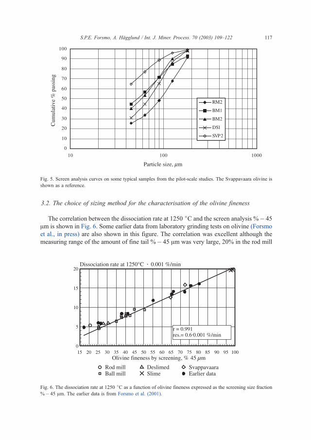
3.2. The choice of sizing method for the characterisation of the olivine fineness
The correlation between the dissociation rate at 1250 jC and the screen analysis %� 45
Am is shown in Fig. 6. Some earlier data from laboratory grinding tests on olivine (Forsmo
et al., in press) are also shown in this figure. The correlation was excellent although the
measuring range of the amount of fine tail %� 45 Am was very large, 20% in the rod mill
Fig. 5. Screen analysis curves on some typical samples from the pilot-scale studies. The Svappavaara olivine is
shown as a reference.
.
Fig. 6. The dissociation rate at 1250 jC as a function of olivine fineness expressed as the screening size fraction
%� 45 Am. The earlier data is from Forsmo et al. (2001).
S.P.E. Forsmo, A. Hagglund / Int. J. Miner. Process. 70 (2003) 109–122 117
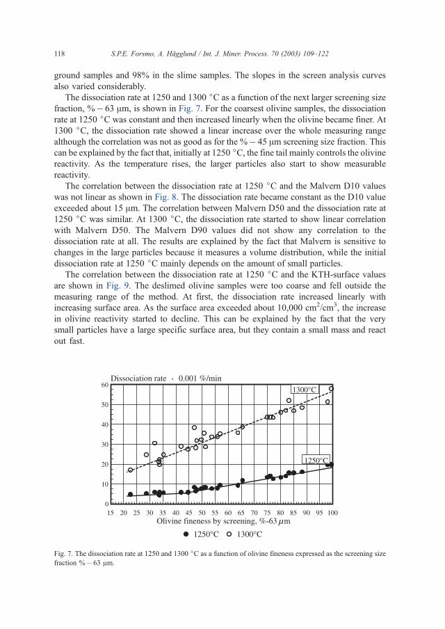
ground samples and 98% in the slime samples. The slopes in the screen analysis curves
also varied considerably.
The dissociation rate at 1250 and 1300 jC as a function of the next larger screening size
fraction, %� 63 Am, is shown in Fig. 7. For the coarsest olivine samples, the dissociation
rate at 1250 jC was constant and then increased linearly when the olivine became finer. At
1300 jC, the dissociation rate showed a linear increase over the whole measuring range
although the correlation was not as good as for the %� 45 Am screening size fraction. This
can be explained by the fact that, initially at 1250 jC, the fine tail mainly controls the olivine
reactivity. As the temperature rises, the larger particles also start to show measurable
reactivity.
The correlation between the dissociation rate at 1250 jC and the Malvern D10 values
was not linear as shown in Fig. 8. The dissociation rate became constant as the D10 value
exceeded about 15 Am. The correlation between Malvern D50 and the dissociation rate at
1250 jC was similar. At 1300 jC, the dissociation rate started to show linear correlation
with Malvern D50. The Malvern D90 values did not show any correlation to the
dissociation rate at all. The results are explained by the fact that Malvern is sensitive to
changes in the large particles because it measures a volume distribution, while the initial
dissociation rate at 1250 jC mainly depends on the amount of small particles.
The correlation between the dissociation rate at 1250 jC and the KTH-surface values
are shown in Fig. 9. The deslimed olivine samples were too coarse and fell outside the
measuring range of the method. At first, the dissociation rate increased linearly with
increasing surface area. As the surface area exceeded about 10,000 cm2/cm3, the increase
in olivine reactivity started to decline. This can be explained by the fact that the very
small particles have a large specific surface area, but they contain a small mass and react
out fast.
.
Fig. 7. The dissociation rate at 1250 and 1300 jC as a function of olivine fineness expressed as the screening size
fraction %� 63 Am.
S.P.E. Forsmo, A. Hagglund / Int. J. Miner. Process. 70 (2003) 109–122118
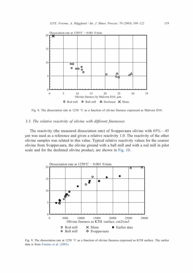
3.3. The relative reactivity of olivine with different finenesses
The reactivity (the measured dissociation rate) of Svappavaara olivine with 65%� 45
Am was used as a reference and given a relative reactivity 1.0. The reactivity of the other
olivine samples was related to this value. Typical relative reactivity values for the coarser
olivine from Svappavaara, the olivine ground with a ball mill and with a rod mill in pilot
scale and for the deslimed olivine product, are shown in Fig. 10.
.
Fig. 8. The dissociation rate at 1250 jC as a function of olivine fineness expressed as Malvern D10.
.
Fig. 9. The dissociation rate at 1250 jC as a function of olivine fineness expressed as KTH surface. The earlier
data is from Forsmo et al. (2001).
S.P.E. Forsmo, A. Hagglund / Int. J. Miner. Process. 70 (2003) 109–122 119
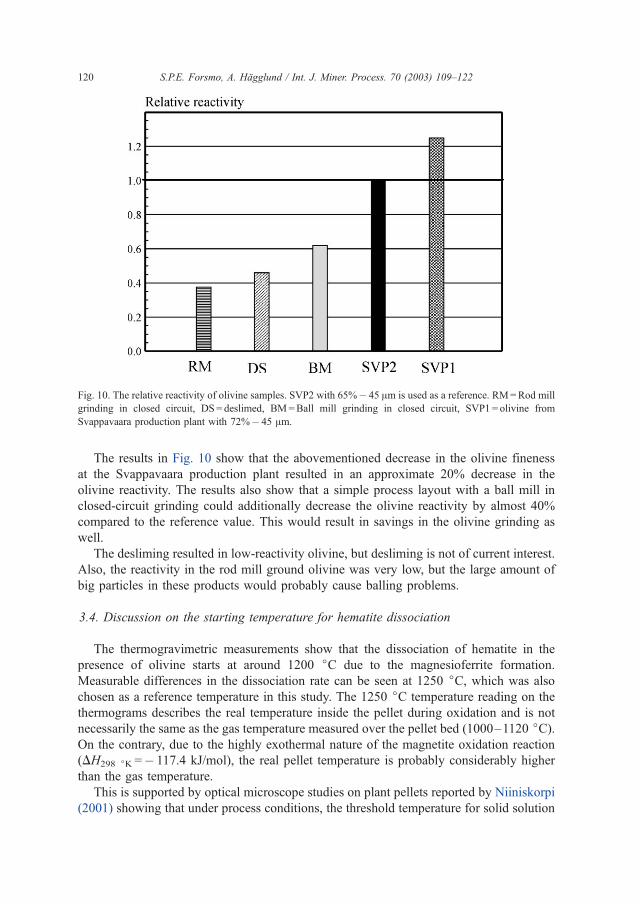
The results in Fig. 10 show that the abovementioned decrease in the olivine fineness
at the Svappavaara production plant resulted in an approximate 20% decrease in the
olivine reactivity. The results also show that a simple process layout with a ball mill in
closed-circuit grinding could additionally decrease the olivine reactivity by almost 40%
compared to the reference value. This would result in savings in the olivine grinding as
well.
The desliming resulted in low-reactivity olivine, but desliming is not of current interest.
Also, the reactivity in the rod mill ground olivine was very low, but the large amount of
big particles in these products would probably cause balling problems.
3.4. Discussion on the starting temperature for hematite dissociation
The thermogravimetric measurements show that the dissociation of hematite in the
presence of olivine starts at around 1200 jC due to the magnesioferrite formation.
Measurable differences in the dissociation rate can be seen at 1250 jC, which was also
chosen as a reference temperature in this study. The 1250 jC temperature reading on the
thermograms describes the real temperature inside the pellet during oxidation and is not
necessarily the same as the gas temperature measured over the pellet bed (1000–1120 jC).On the contrary, due to the highly exothermal nature of the magnetite oxidation reaction
(DH298 jK =� 117.4 kJ/mol), the real pellet temperature is probably considerably higher
than the gas temperature.
This is supported by optical microscope studies on plant pellets reported by Niiniskorpi
(2001) showing that under process conditions, the threshold temperature for solid solution
Fig. 10. The relative reactivity of olivine samples. SVP2 with 65%� 45 Am is used as a reference. RM=Rod mill
grinding in closed circuit, DS = deslimed, BM=Ball mill grinding in closed circuit, SVP1 = olivine from
Svappavaara production plant with 72%� 45 Am.
S.P.E. Forsmo, A. Hagglund / Int. J. Miner. Process. 70 (2003) 109–122120
formation is indeed exceeded and magnesioferrite is formed during oxidation in the grate.
Niiniskorpi also found that the alteration of olivine to magnesioferrite was stronger at the
oxidation front compared to the outer shell of the pellet. This observation implies that
besides temperature rise, there is also a temperature gradient in the pellet during oxidation. In
plant pellets, the variations in oxidation conditions in different parts of the bed are, however,
highly variable. In earlier literature, the temperature increase in a magnetite green pellet
during oxidation has been established by several authors including Cooke and Stowasser
(1952), Natesan and Philbrook (1969) and Ruiz et al. (1994), but the magnitude of the
temperature rise has still not been adequately studied. The results of this study point out the
importance of being able to predict and control the real temperature inside the magnetite
pellets during oxidation.
4. Conclusion
In this study, we have indirectly measured the reactivity of olivine to form a solid
solution with the hematite phase in a green pellet by measuring the rate of contemporary
formation of magnetite, i.e., the dissociation rate of hematite. The olivine reactivity values
given here describe how fast the olivine reacts when the threshold temperature for solid
solution formation is exceeded for one reason or another. A less reactive olivine makes the
pelletizing process more tolerant of excessively high temperatures in the green pellets
during oxidation. This is indicated by higher reduction strength values as shown by our
earlier pot furnace studies. In this study, we could also verify the positive influence of
coarser olivine on the pellet reduction strength in full production scale. Decreasing the
olivine control value from 72% to 65%� 45 Am by screening raised the pellet low
temperature reduction strength (ISO 13930) measured in samples taken at the pelletizing
plant from 92F 2(1r)% + 6.3 mm to 95F 1(1r)% + 6.3 mm.
The pilot-scale grinding tests shows that if the olivine additive is ground in closed
circuit with a ball mill while maintaining good control over the top size, an appreciably
coarser olivine product could be used without disturbing balling. The coarser ground
would further decrease the olivine reactivity during oxidation on the grate. The closed-
circuit grinding would slightly complicate the process layout; on the other hand, savings
can be made on both the grinding energy and grinding media consumption.
The developed thermogravimetric measuring method for olivine reactivity made it
possible to evaluate different particle-sizing methods for olivine characterisation. The
screening size fraction %� 45 Am showed a good correlation to olivine reactivity within a
very large measuring range. The use of a laser diffraction measuring method, such as
Malvern, would have been preferred because it would enable fast and easy analysis. The
correlation of Malvern values to the olivine reactivity showed, however, that Malvern is
affected too much by variations in the large particles. The Malvern measurement could
probably be refined if the larger particles were screened off before Malvern measurement.
This will be studied further.
The thermogravimetric measuring method presented in this study can also be used to
evaluate the reactivity of other olivine deposits in comparison to the Aheim olivine. It can
also be used to evaluate the reactivity of other minerals, especially magnesium-bearing
S.P.E. Forsmo, A. Hagglund / Int. J. Miner. Process. 70 (2003) 109–122 121

minerals, like dolomite. The results obtained in this study are valuable for both process
design and control.
Acknowledgements
Funding from the Agricola Research Centre (ARC) at the Lulea University of
Technology, Sweden, is gratefully acknowledged.
References
Button, R.A., 1989. Olivine assimilation in magnetite based pellets. LKAB Internal Report (unpublished).
Cooke, S.R.B., Stowasser, W.F., 1952. The effect of heat treatment and certain additives on the strength of
magnetite pellets. Trans. AIME 193, 1223–1230.
Eriksson, B.-O., Wikstrom, J.-O., Ahnqvist, A., 1984. Blast furnace operation with 100% pelletburden in SSAB’s
no. 2 BF at Lulea works. Scand. J. Metall. 13, 316–318.
Ferreira, S., Siguin, D., Garcia, F., 1994. Thermal analysis of sintering of magnetite pellets. Ironmak. Steelmak.
21 (2), 119–123.
Forsmo, S., Forsmo, S.-E., Oberg, E., 2001. LKAB contribution to the European Coal and Steel Community
research contract No. 7215-PP/001 (in press).
International standard ISO 13320-1:1999. Particle size analysis-Laser diffraction methods: Part 1. General
principles.
Monsen, B., 1992. Iron ore concentrates—oxidation and reduction. PhD Thesis, Technical University of Trond-
heim, Norway.
Natesan, K., Philbrook, W.O., 1969. Mathematical model for reaction rate and temperature profile during
oxidation of magnetite pellets. Ironmaking Conference, Toronto, Canada, April 14–16, 1969, TSM/AIME
New York, 411–426.
Niiniskorpi, V., 2001. Phases and microstructures in LKAB’s olivine- and dolomite-fluxed pellets. Proceedings
from the 60th ironmaking conference, March 25–28, 2001, Iron & Steel Society, Baltimore, 767–780.
Ruiz, J.C., Badie, J.M., Janna, F.C., 1994. Non-isothermal conditions inside magnetite pellet due to its oxidation
by air. Ironmak. Steelmak. 21 (2), 114–117.
Samskog, P.-O., Broussad, A., Chaigneau, R., Mertins, E., Forssberg, E., 2002. Improvement of blast furnace
pellet quality through an integrated analysis of the product chain and process modelling, Final report on ECSC
project Contract No 7215-PP/001, Report EUR 20291 EN, Office for Official Publications of the European
Communities, Luxenbourg, pp. 74.
Svensson, J., 1949. Bestamning av specifika ytan pa kross-och malgods enligt gaspermeabilitetsmetoden. Jern-
kontorets Ann., Stockholm 133 (2), 33–86 (in Swedish).
S.P.E. Forsmo, A. Hagglund / Int. J. Miner. Process. 70 (2003) 109–122122

ARTICLE VII
Mechanisms in oxidation and sintering of magnetiteiron ore green pellets
S.P.E. Forsmo, S-E. Forsmo, P-O. Samskog, B.M.T. Björkman
Submitted to Powder Technology (March 2007).
VII


Mechanisms in oxidation and sintering of magnetite iron ore green pellets
S.P.E. Forsmoa,b,*, S-E. Forsmoa, P-O. Samskoga,c, B.M.T. Björkmanb
aLKAB, R&D, SE-98381 Malmberget, Sweden. b Luleå University of Technology, Division of Process Metallurgy, SE-97187 Luleå, Sweden
cLuleå University of Technology, Division of Chemistry, SE-97187 Luleå, Sweden *Corresponding author. E-mail: [email protected] Fax: +46-970-30617
Abstract
Thermal volume changes and oxidation mechanisms in magnetite iron ore green pellets balled with 0.5% bentonite binder, as a function of raw material fineness and pellet porosity, are shown. When a pellet starts to oxidize, a shell of hematite is formed around the pellet while the core still is magnetite. Dilatation curves were measured under non-oxidizing and oxidizing atmospheres to separately describe thermal volume changes in these two phases. Dilatation measurements showed contraction during oxidation between 330 and 900°C by 0.5%. The extent of contraction was not influenced by the raw material fineness or the original porosity in pellets. Sintering started earlier in the magnetite phase (950°C) compared to the hematite phase (1100°C). The sintering rate increased with increasing fineness in the magnetite concentrate. A finer grind in the raw material would, therefore, promote the formation of duplex structures with a more heavily sintered core pulling away from the less sintered outer shell.
At constant porosity in green pellets, the oxidation time became longer as the magnetite concentrate became finer, because of the enhanced sintering. In practical balling, however, the increase in fineness would necessitate the use of more water in balling, which results in an increase in green pellet porosity. These two opposite effects levelled out and the oxidation time became constant when green pellets were balled at constant plasticity. Combining the results from the oxidation and dilatation studies revealed new information on the rate limiting factors in oxidation of iron ore pellets. At 1100oC, the diffusion rate of oxygen was limited by sintering in the magnetite core, taking place before oxidation rather than by the diffusion rate of oxygen through the oxidized hematite shell, as has been claimed in earlier literature. The oxidation rate was at maximum at around 1100oC. At 1200oC, the rate of oxidation substantially decreased because both the hematite shell and the magnetite core show heavy sintering at this temperature.
Dilatometer measurements showed large thermal volume changes in the presence of olivine, at temperatures above 1200oC. This is explained by the dissociation of hematite back to magnetite. Dissociation leads to an increase in the volume of the oxidized shell, while sintering of the magnetite core is further enhanced by the olivine additive.
Keywords: Magnetite; Agglomeration; Oxidation; Dilatation; Green pellets; Iron ore; Pelletizing
1
1. Introduction
Magnetite iron ore pellets are produced by agglomerating moist, finely ground magnetite concentrate together with a binder in balling drums or balling discs to pellets, typically between 9 and 15 mm in diameter. In the Grate Kiln pelletizing process, the wet green pellets are loaded on a travelling grate with a bed height of 23 cm. This bed of wet green pellets is transported through the drying zones, updraft drying (UDD) and downdraft drying (DDD). After the drying zones, the upper part of the pellet bed is dry and warm, around 250oC, while the bottom of the bed is still humid. After drying, the bed of green pellets is transported through the temperate preheat zone (TPH) and the preheat zone (PH), where the main part of magnetite oxidation takes place. The temperature of the incoming gas at the PH zone is around 1150 – 1250oC. The gas flow rate is in the order of 6 m/s and the oxygen content of the gas is 16 to 18%. The travelling time through the TPH and PH zones is 6 to 7 minutes. During this time, the upper part of the pellet bed is heated up to the gas temperature, while the bottom of the pellet bed barely reaches 1000oC. From the PH zone the pellets are transferred to a rotating kiln and sintered at around 1270oC. Little or no oxidation takes place in the kiln, due to the high temperature. Even some dissociation of hematite back to magnetite can occur. Final oxidation takes place when pellets are cooled in an annular cooler to below 50oC. Thereafter, pellets are ready for transportation to steelmaking plants.
The oxidation of magnetite iron ore pellets is an important issue for several reasons. The oxidation reaction, shown in Eq. (1), is highly exothermic and releases a major part of the total energy required in sintering. Oxidation of magnetite leads to strong bondings in contact points [1], which reduces the generation of dust when pellets are loaded into the kiln. A constant level of oxidation in magnetite pellets is also of importance for process stability. Variations in the degree of oxidation in pellets leaving the PH zone leads to fluctuations in the amount of oxidation that takes place in the cooler and in the temperature of the recuperated air.
4 FeO Fe2O3 + O2 = 6 Fe2O3 H = -119 kJ/mol (1)
The oxidation and thermal history of pellets also influence the final pellet quality. The so-called duplex structure, with a more heavily sintered core pulling away from the less sintered outer shell, was described in literature as early as the 1950s [1-3]. The duplex structure forms, because in the pelletizing process, only the outer shell of pellets is oxidized before the sintering temperature is reached. A distinct concentric oxidation front between the oxidized outer shell and the non-oxidized core is found in pellets oxidized at temperatures above 1000oC [2,3]. The magnetite core shrinks more than the oxidized hematite shell [1-3] and gives rise to the duplex structure. Structural stress and in extreme cases, concentric cracks, form along the structural boundary. An extreme solution would be complete oxidation of pellets before sintering is started, as suggested by Cooke and Stowasser [3], who called this process double-firing. According to Haas et al. [5], enriching the oxidizing gas in the PH zone to around 30% oxygen and controlling the speed of temperature rise in the PH zone to below 150oC/min, would lead to improved pellet quality.
Several comprehensive studies on the oxidation mechanisms in magnetite iron ore pellets have been published since the early 1950s [1-11]. The influence of partial pressure of oxygen [6,7], pellet porosity [7], pellet size [1,4,6], magnetite concentrate fineness [7] and calcining [11] on the oxidation of pellets has been described. Oxidation of the outer shell of pellets is fast and controlled by the rate of the chemical reaction [7,8]. After the fast superficial
2
oxidation, the oxidation rate is claimed to be controlled by the diffusion rate of oxygen through the growing product layer [7,8]. Zetterström [6] showed that the reciprocal of the time needed to reach a given degree of oxidation in pellets was linearly dependent on the partial pressure of oxygen, which is the driving force for diffusion. According to Zetterström [6], the time needed for 80% oxidation of pellets at 900oC was 8 minutes with 21% O2 in the oxidizing gas (Scrub Oak magnetite, particle size 78%-44 μm, pellet size 9 to 19 mm). The initial oxidation rate in pellets measured at 1000oC has been shown to increase linearly with the partial pressure of oxygen [7]. The influence of pellet porosity was studied by Papanastassiou and Bitsianes [7] using pellets prepared by compaction instead of rolling. The studied range in porosity was very large, between 22 and 42%. This large variation was accomplished partly by using different compression forces in the mould and partly by pre-heating the samples at 1250oC in nitrogen for 30 minutes before oxidation to cause additional shrinkage. The measured time needed for 80% oxidation was about 3 minutes at 1100oC, in air (particle size 100% -31 μm, pellet diameter 12 mm). The time needed to obtain a given degree of oxidation in pellets has been found to be proportional to the square of the diameter of the pellet [1,4].
Very limited data regarding the influence of magnetite concentrate fineness on the oxidation rate in pellets was found in earlier literature. Zetterström [6] showed oxidation curves for pellets prepared from two different magnetite concentrates, artificially prepared to similar raw material fineness. Only oxidation at a very low temperature, at 700oC, was measured. The conclusion was that particle size accounts for only part of the measured difference in oxidation rate. Although the oxidation and sintering phenomena show complex interdependency during the formation of the duplex structure, only a few dilatometer studies on magnetite iron ore pellets have been published [1,4,6]. Contraction in pellets during oxidation [4,6] and incipient sintering at 900oC has been reported [1,4]. Ilmoni and Uggla [1] showed that at 1230oC, shrinkage in the magnetite phase was about 1.4 times larger than in the hematite phase. They also showed that shrinkage in pellets increased with increasing specific surface area in the magnetite raw material. Linear thermal expansion during heating from 20 to 400°C has been measured to be 0.4% for both magnetite and hematite [12]. Linear thermal expansion in magnetite during heating from 20 to 1000°C has been measured to be 1.4% [12]. For hematite, values for thermal expansion at temperatures above 400°C were not found.
The influence of variations in the magnetite concentrate fineness on the behaviour of green pellets during balling and induration is an important issue for the practical control of a full-scale pelletizing plant. Slight variations in these parameters can hardly be avoided. An earlier study showed that if the raw material fineness increases, the green pellet moisture content (and porosity) needs to be increased as well, to retain plasticity and good ballability in the balling circuits [13,14]. In the present work, oxidation and sintering mechanisms in iron ore green pellets under non-sintering and sintering conditions were studied. The intent was to get more information about the sensitivity of the formation of duplex structures for variations in raw material fineness and in green pellet porosity.
3

2. Materials and methods
2.1 Magnetite concentrate raw materials and green pellet properties
Five magnetite pellet concentrate samples were collected from the LKAB (Luossavaara-Kiirunavaara AB, Sweden) Malmberget concentrating plant by varying the feed rate into the grinding mill. Complete particle size data was published earlier [13]. Some key figures on screening analysis and the specific surface areas are shown in Table 1. The Malmberget pellet concentrate (MPC) samples are arranged in order of increasing fineness. Sample MPC-2 represents typical process fineness. The samples contained 71.1% Fe (23.7% Fe2+) and 0.4% SiO2. The density was 5.12 g/cm3.
Table 1. Fineness in the magnetite concentrate raw materials, moisture content and porosity in green pellets.
Sample Specific Screening Green pellets at Green pellets atname surface area constant porosity constant plasticity
-45 μm -63 μm -90 μm Moisture Porosity Moisture Porositycm2/cm3 % % % % % % %
MPC-1 9491 66.1 77.5 88.5 8.6 32.4 8.0 29.7MPC-2 10038 68.8 80.3 90.5 8.6 31.8 7.9 29.7MPC-3 10774 71.7 81.7 91.3 8.7 31.2 8.3 30.3MPC-4 11606 75.4 84.9 93.3 8.7 31.8 8.5 30.7MPC-5 12386 77.2 86.7 94.7 8.7 32.2 8.7 32.2
These raw materials were balled in a laboratory drum to green pellets using methods described earlier in detail [14]. 0.5% bentonite was used as a binder. The moisture content was kept constant (8.7%), which resulted in constant porosity (31.9 ± 0.5%), see Table 1. Dried green pellets (105oC, overnight) were used in the oxidation and dilatation studies. The coarsest and finest raw materials, MPC-1 and MPC-5, were also balled at different levels of porosity in green pellets. The MPC-5 raw material was additionally balled after mixing 3.5% olivine (65% -45 μm by sieving) with the magnetite raw material. All five samples were also balled at the material specific moisture content (at constant plasticity) [13], see Table 1. Porosity was measured on dried green pellets by the GeoPyc 1360 instrument (Micromeritics Inc.) and absolute density by the AccuPyc 1330 gas displacement pycnometer (Micromeritics Inc.). These methods have been described earlier in detail [15]. In the GeoPyc instrument, the green pellet volume is measured by packing the sample in silica sand. Before measuring, the green pellets were strengthened by spraying with a lacquer.
2.2 Dilatometer measurements
A Setaram TMA96 instrument was used in the dilatometer measurements. The pellets were prepared to constant size of 10 mm by rotating them in a 10 mm hole, stamped in a steel plate. Olsen and Malvik [9] used the same preparation method. In the TMA96 instrument, the sample was placed on an Al2O3 sample holder and an Al2O3 push rod was used to detect variations in sample dimensions as a function of the furnace temperature or time. A weight of 5 g was applied to the push rod to get good contact with the sample. The sample temperature was measured with a thermocouple fastened to the Al2O3 sample holder, at about 3 mm distance from the pellet sample. A slow heating rate (5oC/min) was chosen to ensure that the
4

temperature within the green pellet is at all times the same as that read from the thermocouple. Background correction was done by running a 16 mm Al2O3 sphere with the same measuring program as applied for the green pellet samples. Dilatometer measurements were run both under non-oxidizing (99.99990% N2) and oxidizing (16.0% 0.1 % O2 in N2)atmospheres to measure the dimensional changes in the magnetite and hematite phases, separately.
2.3 Thermogravimetric analysis (TGA)
TGA measurements were done using a Setaram 92-16 thermobalance. In this instrument, the sample is suspended from the balance and lowered into the graphite furnace with the help of an elevator. Nitrogen (99.99990% N2) was used as an inert gas and 16.0 0.1 % O2 in N2 was used as the oxidizing gas. As the diameter of the green pellet largely influences the time needed for oxidation [1,4,6], the green pellets were prepared to 10 mm in size using the same method as described above. This is the largest sample diameter that can be run in the TGA 92-16 instrument. The sample weight in green pellets with constant porosity (31.9%) was 1800 ± 25 mg. In green pellets with varying porosity the sample weight followed porosity, being 1840 mg at 30.0% porosity and 1860 mg at 29.0% porosity. Total oxidation weight gain was measured by TGA in magnetite concentrate powder samples with a heating rate of 5°C/min. The total oxidation weight gain was 3.38% (23.6% Fe2+) in all samples.
In earlier literature, several different TGA measuring methods have been used to measure the oxidation rate in iron ore pellets. One method is to allow the sample to reach the desired isothermal temperature under non-oxidizing atmosphere before the oxygen-containing gas, most often air, is turned on [6,7,9]. This method is truly isothermal but there are two draw-backs, both of which tend to decrease the measured oxidation rate. First, the oxidizing gas is diluted by the inert gas in the beginning of the oxidation experiment [16] and the initial rate of oxidation will be too low. Secondly, if this method is used in temperatures above 800oC,sintering would take place before oxidation and suppress the oxidation rate. The degree of sintering could depend on the applied time for pre-heating. Another method that has been used is to pre-heat the sample at around 500oC in air before measuring the oxidation rate [4]. This was deemed justifiable, because the extent of oxidation in temperatures below 500oCwas considered too small to be relevant for the subsequent pelletizing process. However, in magnetite pellet concentrates of typical pelletizing fineness, as much as 10 to 25% of all oxidation can take place already at temperatures below 400oC [6,17]. This oxidation is very fast and adds to the heat development during the fast oxidation of the pellet outer shell. Finally, if no heat pre-treatment is done before registering the oxidation weight gain [8], any loss of weight, like calcining and especially dehydration of the bentonite binder, would take place during the oxidation period and diminish the measured weight gain. Bentonite contains both free water (about 10%) and structurally bound water (about 10%), which is lost between 500 and 800oC.
In this study, the pellet sample was pre-heated in the TGA92 instrument, in a platinum wire basket, to 800oC under nitrogen atmosphere for 60 minutes. The pellet was then cooled back to room temperature at a cooling rate of 20oC/min. At 800oC in inert gas, only normal thermal expansion takes place. The pre-heated and cooled green pellet in the wire basket was then weighed and hanged back to the TGA balance. The green pellet weight decreased with 0.22% (about 4 mg) during pre-heating. The oxidation experiment was started by heating the furnace to the desired temperature, while flushing with the oxidizing gas. At this stage, the sample
5
elevator was in the upper position with the sample hanging outside the furnace. The sample inlet of the furnace was closed with a plate. The oxidation measurement was started by lowering the sample in the hot furnace. Using this method, the oxygen content in the oxidizing gas is constant. The first part of oxidation takes place non-isothermally as the sample temperature rises from room temperature to the furnace temperature. This is also the main oxidation pattern for pellets in a full-scale pelletizing process.
Lowering the sample elevator in the TGA92 instrument takes 24 seconds. This time was deducted from the total oxidation time. At 800oC, the subtraction of the 24 seconds makes the oxidation time a few seconds too short, because the heating of the pellet is already started when it enters the upper part of the hot zone. At 1100oC and 1200oC, heat transfer takes place by radiation and the heat hits the sample as soon as it enters the upper part of the furnace. In this case, heating starts about 10 seconds before the pellet reaches its final position in the hot zone. These errors are considered marginal. Background correction was done by running two annealed Al2O3 spheres with about the same weight as the green pellet. The background run showed a 1 mg increase in sample weight, as a step-change directly after descending the Al2O3 sample in the furnace. This was subtracted from the oxidation run. This kind of background correction does not correct for the apparent weight loss at the Curie point [17], which can vary depending on the degree of oxidation in the pellet when the Curie point is reached. Therefore, the total oxidation weight gains obtained for pellets in these experiments are slightly too low. These errors are marginal and do not change the interpretation of the oxidation data.
3. Results
3.1 Interpretation of the dilatation curves
When a pellet starts to oxidize, a shell of hematite is formed around the pellet while the core is still magnetite. Displacement curves (Disp) and corresponding derivate curves (dDisp) were measured under non-oxidizing and oxidizing atmospheres to separately describe thermal volume changes in these two phases. The dilatation curve collected under nitrogen atmosphere is used to describe the behaviour of the magnetite core in pellets. The dilatation curve collected under oxidizing atmosphere is used to describe the behaviour of the oxidized hematite shell in pellets.
Dilatation curves for green pellets prepared of the MPC-5 raw material run under non-oxidizing and oxidizing atmospheres are shown in Fig. 1 (Disp) and Fig. 2 (dDisp). Under non-oxidizing atmosphere, linear expansion up to 800oC was found. The breakpoint seen at 570oC is the Curie point. The apparent linear coefficient of expansion ( e*) in nitrogen atmosphere, between 100 and 800oC, was calculated to be 6.1 x 10⁻⁶ /oC. This figure is impaired by some inaccuracy because of the disturbance in the Curie point. Between 800 and 950oC, slight shrinkage took place and thereafter, vigorous sintering started. At 1200oC, the apparent linear coefficient of shrinkage ( s*) in the magnetite pellet (in N2) became near constant (-149 x 10-6/oC).
The dilatation curves measured under oxidizing atmosphere showed quite different behaviour. The sample showed measurable contraction starting already at 330oC. This is near to the temperature at which -hematite, formed during the low temperature oxidation of magnetite, has been found to assume the -hematite structure [17]. The dilatation curve showed linear
6
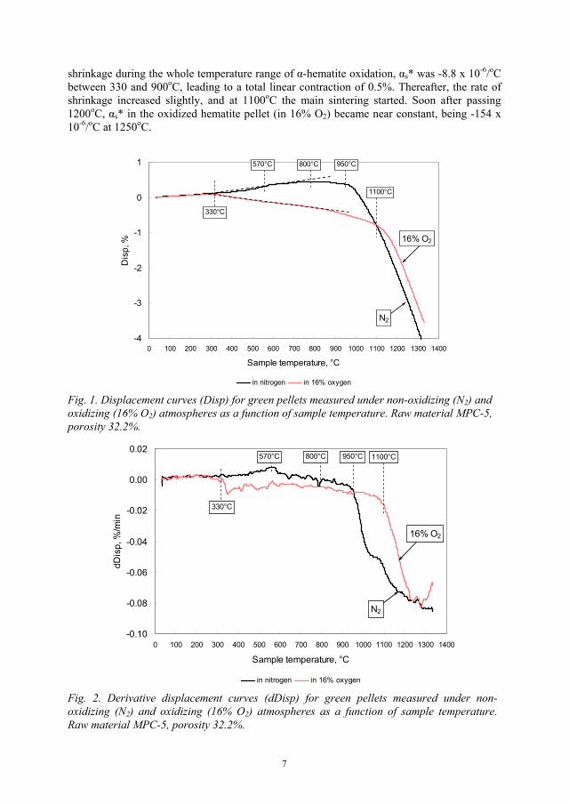
shrinkage during the whole temperature range of -hematite oxidation, s* was -8.8 x 10⁻⁶/oCbetween 330 and 900oC, leading to a total linear contraction of 0.5%. Thereafter, the rate of shrinkage increased slightly, and at 1100oC the main sintering started. Soon after passing 1200oC, s* in the oxidized hematite pellet (in 16% O2) became near constant, being -154 x 10-6/oC at 1250oC.
-4
-3
-2
-1
0
1
0 100 200 300 400 500 600 700 800 900 1000 1100 1200 1300 1400
Sample temperature, °C
Dis
p, %
in nitrogen in 16% oxygen
N2
16% O2
330°C
570°C 800°C 950°C
1100°C
Fig. 1. Displacement curves (Disp) for green pellets measured under non-oxidizing (N2) and oxidizing (16% O2) atmospheres as a function of sample temperature. Raw material MPC-5, porosity 32.2%.
-0.10
-0.08
-0.06
-0.04
-0.02
0.00
0.02
0 100 200 300 400 500 600 700 800 900 1000 1100 1200 1300 1400
Sample temperature, °C
dDis
p, %
/min
in nitrogen in 16% oxygen
N2
16% O2
330°C
570°C 800°C 950°C 1100°C
Fig. 2. Derivative displacement curves (dDisp) for green pellets measured under non-oxidizing (N2) and oxidizing (16% O2) atmospheres as a function of sample temperature. Raw material MPC-5, porosity 32.2%.
7
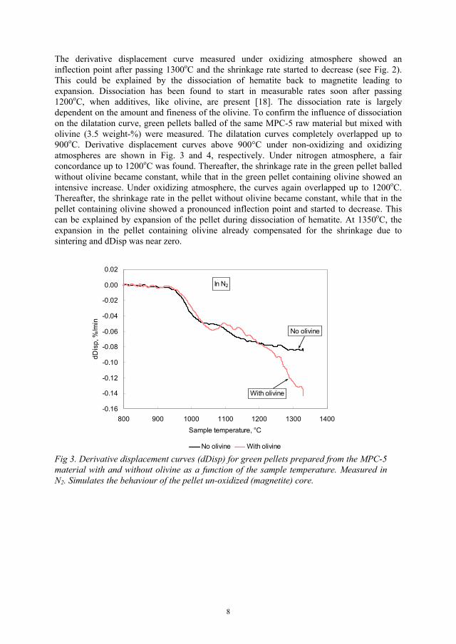
The derivative displacement curve measured under oxidizing atmosphere showed an inflection point after passing 1300oC and the shrinkage rate started to decrease (see Fig. 2). This could be explained by the dissociation of hematite back to magnetite leading to expansion. Dissociation has been found to start in measurable rates soon after passing 1200oC, when additives, like olivine, are present [18]. The dissociation rate is largely dependent on the amount and fineness of the olivine. To confirm the influence of dissociation on the dilatation curve, green pellets balled of the same MPC-5 raw material but mixed with olivine (3.5 weight-%) were measured. The dilatation curves completely overlapped up to 900oC. Derivative displacement curves above 900°C under non-oxidizing and oxidizing atmospheres are shown in Fig. 3 and 4, respectively. Under nitrogen atmosphere, a fair concordance up to 1200oC was found. Thereafter, the shrinkage rate in the green pellet balled without olivine became constant, while that in the green pellet containing olivine showed an intensive increase. Under oxidizing atmosphere, the curves again overlapped up to 1200oC. Thereafter, the shrinkage rate in the pellet without olivine became constant, while that in the pellet containing olivine showed a pronounced inflection point and started to decrease. This can be explained by expansion of the pellet during dissociation of hematite. At 1350oC, the expansion in the pellet containing olivine already compensated for the shrinkage due to sintering and dDisp was near zero.
-0.16
-0.14
-0.12
-0.10
-0.08
-0.06
-0.04
-0.02
0.00
0.02
800 900 1000 1100 1200 1300 1400Sample temperature, °C
dDis
p, %
/min
No olivine With olivine
With olivine
No olivine
In N2
Fig 3. Derivative displacement curves (dDisp) for green pellets prepared from the MPC-5 material with and without olivine as a function of the sample temperature. Measured in N2. Simulates the behaviour of the pellet un-oxidized (magnetite) core.
8
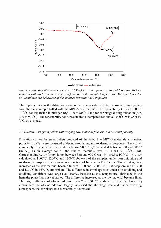
-0.16
-0.14
-0.12
-0.10
-0.08
-0.06
-0.04
-0.02
0.00
0.02
800 900 1000 1100 1200 1300 1400Sample temperature, °C
dDis
p, %
/min
No olivine With olivine
With olivine
No olivine
In 16% O2
Fig. 4. Derivative displacement curves (dDisp) for green pellets prepared from the MPC-5 material with and without olivine as a function of the sample temperature. Measured in 16% O2. Simulates the behaviour of the oxidized hematite shell in pellets.
The repeatability in the dilatation measurements was estimated by measuring three pellets from the same sample balled with the MPC-5 raw material. The repeatability (1 ) was ±0.2 x 10⁻⁶/oC for expansion in nitrogen ( e*, 100 to 800oC) and for shrinkage during oxidation ( s*,330 to 900oC). The repeatability for s*calculated at temperatures above 1000oC was ±5 x 10-
6/oC, on average.
3.2 Dilatation in green pellets with varying raw material fineness and constant porosity
Dilatation curves for green pellets prepared of the MPC-1 to MPC-5 materials at constant porosity (31.9%) were measured under non-oxidizing and oxidizing atmospheres. The curves completely overlapped at temperatures below 900oC. e* calculated between 100 and 800oC(in N2), as an average for all the studied materials, was 6.0 ± 0.1 x 10⁻⁶/oC (1 ).Correspondingly, s* for oxidation between 330 and 900oC was -9.1 ± 0.5 x 10⁻⁶/oC (1 ). s*calculated at 1100oC, 1200°C and 1300°C for each of the samples, under non-oxidizing and oxidizing atmospheres, are shown as a function of fineness in Fig. 5a to c. The shrinkage rate increased as the raw material became finer at 1100 and 1200oC in N2 atmosphere and at 1200 and 1300oC in 16% O2 atmosphere. The difference in shrinkage rates under non-oxidizing and oxidizing conditions was largest at 1100°C, because at this temperature, shrinkage in the hematite phase has not yet started. The difference increased as the raw material became finer. The large influence of olivine addition on s* at 1300°C is shown in Fig. 5c. Under N2atmosphere the olivine addition largely increased the shrinkage rate and under oxidizing atmosphere, the shrinkage rate substantially decreased.
9

-300
-250
-200
-150
-100
-50
0
64 66 68 70 72 74 76 78 80Screening %-45 μm
s* x
10-6
, °C
-1
in 16%O2 with olivine in 16% O2 in N2 with olivine in N2
1100°C
in 16%O2 16%O2
N2N2
(a)
-300
-250
-200
-150
-100
-50
0
64 66 68 70 72 74 76 78 80Screening %-45 μm
s* x
10-6
, °C
-1
in 16%O2 with olivine in 16% O2 in N2 with olivine in N2
1200°C
in 16%O2
in N2
16%O2
N2
(b)
-300
-250
-200
-150
-100
-50
0
64 66 68 70 72 74 76 78 80Screening %-45 μm
s* x
10-6
, °C
-1
in 16%O2 with olivine in 16% O2 in N2 with olivine in N2
1300°C
N2 N2
in 16%O2 in 16%O2
(c)Fig. 5a-c. Apparent linear shrinkage coefficient ( s*) in green pellets as a function of raw material fineness at 1100°C, 1200°C and 1300°C. Measured in N2 and in 16% O2. Results for green pellets prepared from MPC-5 (77.2% -45 μm) and containing 3.5% olivine are shown, as well.
3.3 Interpretation of the oxidation curves at 800oC furnace temperature
The oxidation studies were started at 800oC because at this temperature, the oxidation rate is not influenced by sintering. Understanding the oxidation phenomena at 800oC helps to interpret the oxidation curves at higher temperatures. Oxidation curves, weight gain (TG) and
10
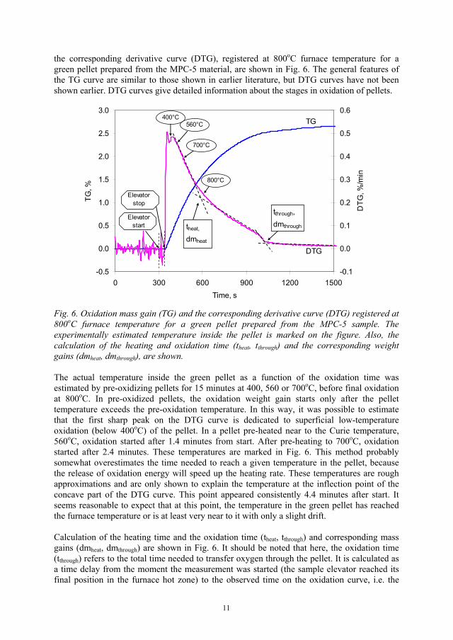
the corresponding derivative curve (DTG), registered at 800oC furnace temperature for a green pellet prepared from the MPC-5 material, are shown in Fig. 6. The general features of the TG curve are similar to those shown in earlier literature, but DTG curves have not been shown earlier. DTG curves give detailed information about the stages in oxidation of pellets.
-0.5
0.0
0.5
1.0
1.5
2.0
2.5
3.0
0 300 600 900 1200 1500Time, s
TG, %
-0.1
0.0
0.1
0.2
0.3
0.4
0.5
0.6
DTG
, %/m
in
tthrough,dmthroughtheat,
dmheat
800°C
700°C
560°C400°C
Elevatorstart
Elevatorstop
TG
DTG
Fig. 6. Oxidation mass gain (TG) and the corresponding derivative curve (DTG) registered at 800oC furnace temperature for a green pellet prepared from the MPC-5 sample. The experimentally estimated temperature inside the pellet is marked on the figure. Also, the calculation of the heating and oxidation time (theat, tthrough) and the corresponding weight gains (dmheat, dmthrough), are shown.
The actual temperature inside the green pellet as a function of the oxidation time was estimated by pre-oxidizing pellets for 15 minutes at 400, 560 or 700oC, before final oxidation at 800oC. In pre-oxidized pellets, the oxidation weight gain starts only after the pellet temperature exceeds the pre-oxidation temperature. In this way, it was possible to estimate that the first sharp peak on the DTG curve is dedicated to superficial low-temperature oxidation (below 400oC) of the pellet. In a pellet pre-heated near to the Curie temperature, 560oC, oxidation started after 1.4 minutes from start. After pre-heating to 700oC, oxidation started after 2.4 minutes. These temperatures are marked in Fig. 6. This method probably somewhat overestimates the time needed to reach a given temperature in the pellet, because the release of oxidation energy will speed up the heating rate. These temperatures are rough approximations and are only shown to explain the temperature at the inflection point of the concave part of the DTG curve. This point appeared consistently 4.4 minutes after start. It seems reasonable to expect that at this point, the temperature in the green pellet has reached the furnace temperature or is at least very near to it with only a slight drift.
Calculation of the heating time and the oxidation time (theat, tthrough) and corresponding mass gains (dmheat, dmthrough) are shown in Fig. 6. It should be noted that here, the oxidation time (tthrough) refers to the total time needed to transfer oxygen through the pellet. It is calculated as a time delay from the moment the measurement was started (the sample elevator reached its final position in the furnace hot zone) to the observed time on the oxidation curve, i.e. the
11
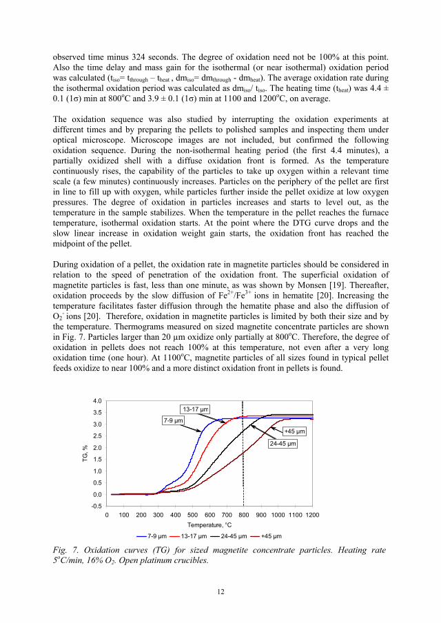
observed time minus 324 seconds. The degree of oxidation need not be 100% at this point. Also the time delay and mass gain for the isothermal (or near isothermal) oxidation period was calculated (tiso= tthrough – theat , dmiso= dmthrough - dmheat). The average oxidation rate during the isothermal oxidation period was calculated as dmiso/ tiso. The heating time (theat) was 4.4 ± 0.1 (1 ) min at 800oC and 3.9 ± 0.1 (1 ) min at 1100 and 1200oC, on average.
The oxidation sequence was also studied by interrupting the oxidation experiments at different times and by preparing the pellets to polished samples and inspecting them under optical microscope. Microscope images are not included, but confirmed the following oxidation sequence. During the non-isothermal heating period (the first 4.4 minutes), a partially oxidized shell with a diffuse oxidation front is formed. As the temperature continuously rises, the capability of the particles to take up oxygen within a relevant time scale (a few minutes) continuously increases. Particles on the periphery of the pellet are first in line to fill up with oxygen, while particles further inside the pellet oxidize at low oxygen pressures. The degree of oxidation in particles increases and starts to level out, as the temperature in the sample stabilizes. When the temperature in the pellet reaches the furnace temperature, isothermal oxidation starts. At the point where the DTG curve drops and the slow linear increase in oxidation weight gain starts, the oxidation front has reached the midpoint of the pellet.
During oxidation of a pellet, the oxidation rate in magnetite particles should be considered in relation to the speed of penetration of the oxidation front. The superficial oxidation of magnetite particles is fast, less than one minute, as was shown by Monsen [19]. Thereafter, oxidation proceeds by the slow diffusion of Fe2+/Fe3+ ions in hematite [20]. Increasing the temperature facilitates faster diffusion through the hematite phase and also the diffusion of O2
- ions [20]. Therefore, oxidation in magnetite particles is limited by both their size and by the temperature. Thermograms measured on sized magnetite concentrate particles are shown in Fig. 7. Particles larger than 20 μm oxidize only partially at 800oC. Therefore, the degree of oxidation in pellets does not reach 100% at this temperature, not even after a very long oxidation time (one hour). At 1100oC, magnetite particles of all sizes found in typical pellet feeds oxidize to near 100% and a more distinct oxidation front in pellets is found.
-0.5
0.0
0.5
1.0
1.5
2.0
2.5
3.0
3.5
4.0
0 100 200 300 400 500 600 700 800 900 1000 1100 1200Temperature, °C
TG, %
7-9 μm 13-17 μm 24-45 μm +45 μm
7-9 μm
+45 μm
24-45 μm
13-17 μm
Fig. 7. Oxidation curves (TG) for sized magnetite concentrate particles. Heating rate 5oC/min, 16% O2. Open platinum crucibles.
12
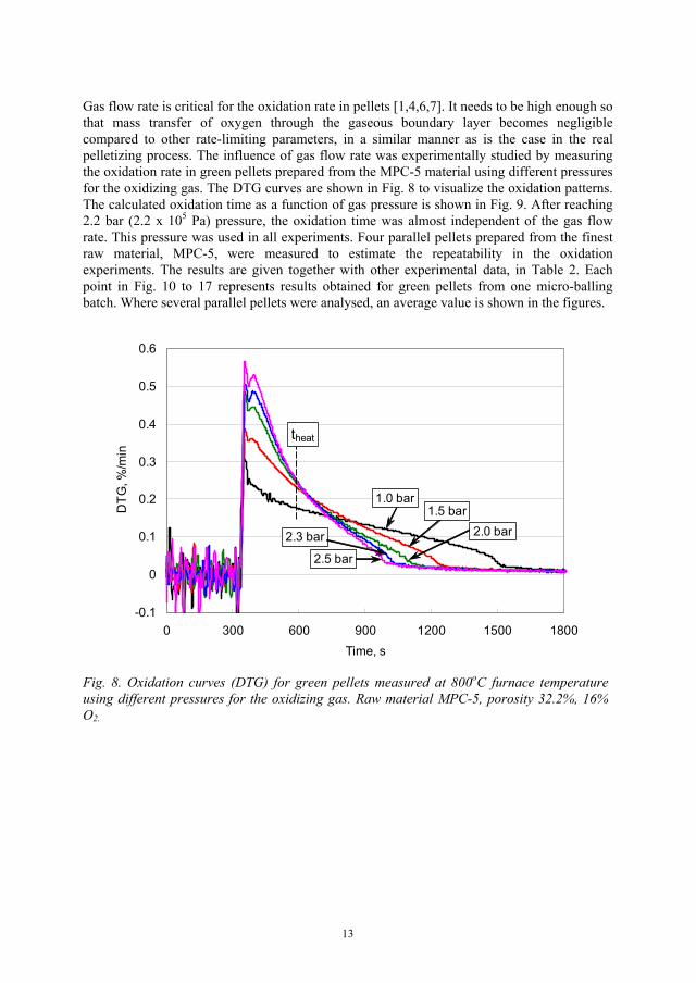
Gas flow rate is critical for the oxidation rate in pellets [1,4,6,7]. It needs to be high enough so that mass transfer of oxygen through the gaseous boundary layer becomes negligible compared to other rate-limiting parameters, in a similar manner as is the case in the real pelletizing process. The influence of gas flow rate was experimentally studied by measuring the oxidation rate in green pellets prepared from the MPC-5 material using different pressures for the oxidizing gas. The DTG curves are shown in Fig. 8 to visualize the oxidation patterns. The calculated oxidation time as a function of gas pressure is shown in Fig. 9. After reaching 2.2 bar (2.2 x 10⁵ Pa) pressure, the oxidation time was almost independent of the gas flow rate. This pressure was used in all experiments. Four parallel pellets prepared from the finest raw material, MPC-5, were measured to estimate the repeatability in the oxidation experiments. The results are given together with other experimental data, in Table 2. Each point in Fig. 10 to 17 represents results obtained for green pellets from one micro-balling batch. Where several parallel pellets were analysed, an average value is shown in the figures.
-0.1
0
0.1
0.2
0.3
0.4
0.5
0.6
0 300 600 900 1200 1500 1800Time, s
DTG
, %/m
in
2.5 bar
2.3 bar
1.0 bar1.5 bar
2.0 bar
theat
Fig. 8. Oxidation curves (DTG) for green pellets measured at 800oC furnace temperature using different pressures for the oxidizing gas. Raw material MPC-5, porosity 32.2%, 16% O2.
13
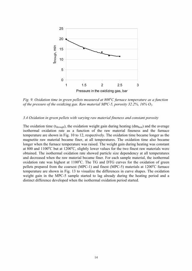
0
5
10
15
20
25
1 1.5 2 2.5 3Pressure in the oxidizing gas, bar
t thro
ugh,
min
Fig. 9. Oxidation time in green pellets measured at 800oC furnace temperature as a function of the pressure of the oxidizing gas. Raw material MPC-5, porosity 32.2%, 16% O2.
3.4 Oxidation in green pellets with varying raw material fineness and constant porosity
The oxidation time (tthrough), the oxidation weight gain during heating (dmheat) and the average isothermal oxidation rate as a function of the raw material fineness and the furnace temperature are shown in Fig. 10 to 12, respectively. The oxidation time became longer as the magnetite raw material became finer, at all temperatures. The oxidation time also became longer when the furnace temperature was raised. The weight gain during heating was constant at 800 and 1100oC but at 1200oC, slightly lower values for the two finest raw materials were obtained. The isothermal oxidation rate showed particle size dependency at all temperatures and decreased when the raw material became finer. For each sample material, the isothermal oxidation rate was highest at 1100oC. The TG and DTG curves for the oxidation of green pellets prepared from the coarsest (MPC-1) and finest (MPC-5) materials at 1200oC furnace temperature are shown in Fig. 13 to visualize the differences in curve shapes. The oxidation weight gain in the MPC-5 sample started to lag already during the heating period and a distinct difference developed when the isothermal oxidation period started.
14
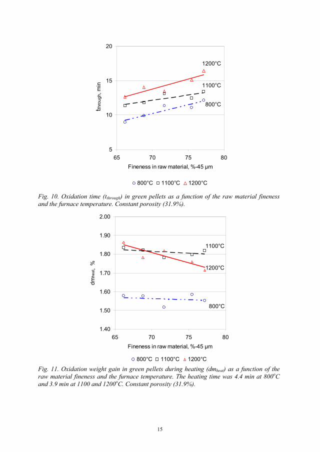
5
10
15
20
65 70 75 80Fineness in raw material, %-45 μm
tthro
ugh,
min
800°C 1100°C 1200°C
800°C
1100°C
1200°C
Fig. 10. Oxidation time (tthrough) in green pellets as a function of the raw material fineness and the furnace temperature. Constant porosity (31.9%).
1.40
1.50
1.60
1.70
1.80
1.90
2.00
65 70 75 80Fineness in raw material, %-45 μm
dmhe
at,
%
800°C 1100°C 1200°C
800°C
1200°C
1100°C
Fig. 11. Oxidation weight gain in green pellets during heating (dmheat) as a function of the raw material fineness and the furnace temperature. The heating time was 4.4 min at 800oCand 3.9 min at 1100 and 1200oC. Constant porosity (31.9%).
15

0.10
0.12
0.14
0.16
0.18
0.20
65 70 75 80Fineness in raw material, %-45 μm
Isot
herm
al o
xida
tion
rate
, %/m
in..
800°C 1100°C 1200°C
1100°C
800°C1200°C
Fig. 12. Average isothermal oxidation rate in green pellets as a function of the raw material fineness and the furnace temperature. Constant porosity (31.9%).
-0.5
0.0
0.5
1.0
1.5
2.0
2.5
3.0
3.5
0 300 600 900 1200 1500 1800Time, s
TG, %
-0.1
0.0
0.1
0.2
0.3
0.4
0.5
0.6
0.7
DTG
, %/m
in
MPC-1 MPC-5
MPC-1
MPC-5
MPC-1 MPC-5
TG
DTG
theat
Fig. 13. TG and DTG curves collected at 1200oC furnace temperature for the oxidation of green pellets prepared from the coarsest (MPC-1) and finest (MPC-5) materials. Constant porosity (31.9%).
16
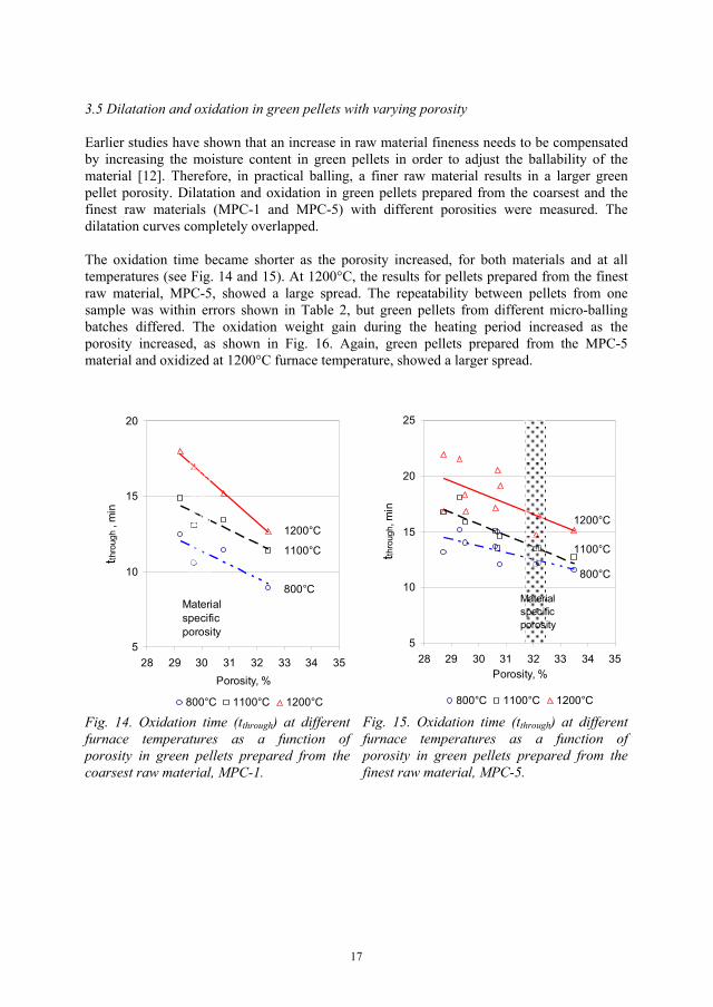
3.5 Dilatation and oxidation in green pellets with varying porosity
Earlier studies have shown that an increase in raw material fineness needs to be compensated by increasing the moisture content in green pellets in order to adjust the ballability of the material [12]. Therefore, in practical balling, a finer raw material results in a larger green pellet porosity. Dilatation and oxidation in green pellets prepared from the coarsest and the finest raw materials (MPC-1 and MPC-5) with different porosities were measured. The dilatation curves completely overlapped.
The oxidation time became shorter as the porosity increased, for both materials and at all temperatures (see Fig. 14 and 15). At 1200°C, the results for pellets prepared from the finest raw material, MPC-5, showed a large spread. The repeatability between pellets from one sample was within errors shown in Table 2, but green pellets from different micro-balling batches differed. The oxidation weight gain during the heating period increased as the porosity increased, as shown in Fig. 16. Again, green pellets prepared from the MPC-5 material and oxidized at 1200°C furnace temperature, showed a larger spread.
5
10
15
20
28 29 30 31 32 33 34 35Porosity, %
tthro
ugh
, min
800°C 1100°C 1200°C
1100°C
800°C
1200°C
Material specificporosity
Fig. 14. Oxidation time (tthrough) at different furnace temperatures as a function of porosity in green pellets prepared from the coarsest raw material, MPC-1.
5
10
15
20
25
28 29 30 31 32 33 34 35Porosity, %
tthro
ugh,
min
800°C 1100°C 1200°C
800°C
1100°C
1200°C
Material specificporosity
Fig. 15. Oxidation time (tthrough) at different furnace temperatures as a function of porosity in green pellets prepared from the finest raw material, MPC-5.
17

1.40
1.50
1.60
1.70
1.80
1.90
2.00
28 29 30 31 32 33 34 35Porosity, %
dmhe
at, %
1100°C MPC-1 1200°C MPC-11100°C MPC-5 1200°C MPC-5
Fig. 16. Oxidation weight gain during heating (dmheat) as a function of green pellet porosity at 1100 and 1200°C furnace temperatures. The green pellets were prepared from MPC-1 and MPC-5 raw materials.
5
10
15
20
65 70 75 80Fineness in raw material, %-45 μm
tthro
ugh,
min
800°C 1100°C 1200°C
800°C
1100°C
1200°C
29.7% 30.3% 30.7% 32.2%
Fig. 17. Oxidation time (tthrough) in green pellets as a function of the raw material fineness and the furnace temperature. Balled at material specific porosity, marked on the figure.
3.6 Dilatation and oxidation in green pellets at material specific porosity
Dilatation and oxidation in green pellets prepared from the five MPC raw materials at moisture contents corresponding to realistic balling conditions for each of the materials (at constant plasticity [13]) were measured. The dilatation curves completely overlapped. The oxidation time at 800, 1100 and 1200°C furnace temperatures as a function of the raw material fineness is shown in Fig. 17. Porosity in each sample is marked on the figure. At 800°C furnace temperature, the oxidation time increased with increasing raw material fineness. At 1100 and 1200°C, the oxidation time became constant; 14 and 16 minutes, respectively.
4. Discussion
When a pellet starts to oxidize, a shell of hematite is formed around the pellet while the core is still magnetite. Dilatation curves were measured under non-oxidizing and oxidizing atmospheres to separately describe thermal volume changes in these two phases. The dilatation curve collected under nitrogen atmosphere is used to describe the behaviour of the magnetite core in pellets. The dilatation curve collected under oxidizing atmosphere is used to describe the behaviour of the oxidized hematite shell in pellets.
These two phases show very different thermal volume changes (Fig. 1 and 2). The un-oxidized magnetite core showed thermal expansion up to 800oC ( e* = 6.0 x 10⁻⁶/oC), while contraction during oxidation between 330 and 900oC by 0.52% ( s* = -9.1 x 10⁻⁶/oC), was
18
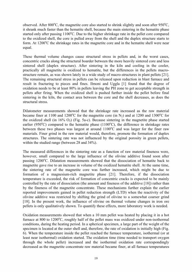
observed. After 800oC, the magnetite core also started to shrink slightly and soon after 950oC, it shrank much faster than the hematite shell, because the main sintering in the hematite phase started only after passing 1100oC. Due to the higher shrinkage rate in the pellet core compared to the oxidized shell, the core is pulled away from the shell and the duplex structure starts to form. At 1200oC the shrinkage rates in the magnetite core and in the hematite shell were near equal.
These thermal volume changes cause structural stress in pellets and, in the worst cases, concentric cracks along the structural boarder between the more heavily sintered core and less sintered shell (duplex structure). After sintering in the kiln and cooling in the cooler, practically all magnetite is oxidized to hematite, but the differences in the pellets macro-structure remain, as was shown lately in a wide study of macro-structures in plant pellets [21]. The remaining structural stress in pellets can be released upon reduction in blast furnace and result in fracturing to pieces and fines. Ilmoni and Uggla [1] found that the degree of oxidation needs to be at least 80% in pellets leaving the PH zone to get acceptable strength in pellets after firing. When the oxidized shell is pushed further inside the pellet before final sintering in the kiln, the contact area between the core and the shell decreases, as does the structural stress.
Dilatometer measurements showed that the shrinkage rate increased as the raw material became finer at 1100 and 1200oC for the magnetite core (in N2) and at 1200 and 1300oC for the oxidized shell (in 16% O2) (Fig. 5a-c). Because sintering in the magnetite phase started earlier (950oC) compared to the hematite phase (1100oC), the difference in shrinkage rates between these two phases was largest at around 1100oC and was larger for the finer raw materials. Finer grind in the raw material would, therefore, promote the formation of duplex structures. The sintering rate was not influenced by the original porosity in green pellets, within the studied range (between 28 and 34%).
The measured differences in the sintering rate as a function of raw material fineness were, however, small compared to the large influence of the olivine additive found soon after passing 1200oC. Dilatation measurements showed that the dissociation of hematite back to magnetite gave rise to an increase in volume of the oxidized hematite shell. At the same time, the sintering rate of the magnetite core was further increased, which might be due to formation of a magnesium-rich magnetite phase [21]. Therefore, if the dissociation temperature is exceeded, the risk of formation of concentric cracks is expected to be mainly controlled by the rate of dissociation (the amount and fineness of the additive [18]) rather than by the fineness of the magnetite concentrate. These mechanisms further explain the earlier reported improvements gained in pellet reduction strength (LTD) when the reactivity of the olivine additive was restricted by shifting the grind of olivine to a somewhat coarser grind [18]. In the present work, the influence of olivine on thermal volume changes in iron ore pellets is only qualitatively shown. To quantify these effects, more laboratory work is needed.
Oxidation measurements showed that when a 10 mm pellet was heated by placing it in a hot furnace at 800 to 1200oC, roughly half of the pellet mass was oxidized under non-isothermal conditions, during the heating period. In a spherical specimen, a large part of the weight of the specimen is located at the outer shell and, therefore, the rate of oxidation is initially high (Fig. 6). When the temperature inside the pellet reached the furnace temperature, isothermal (or at least near isothermal) oxidation started. The oxidation time (time needed to transport oxygen through the whole pellet) increased and the isothermal oxidation rate correspondingly decreased as the magnetite concentrate raw material became finer, at all furnace temperatures
19
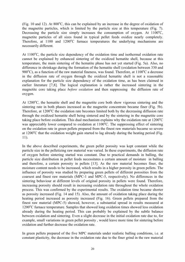
(Fig. 10 and 12). At 800oC, this can be explained by an increase in the degree of oxidation of the magnetite particles, which is limited by the particle size at this temperature (Fig. 7). Decreasing the particle size simply increases the consumption of oxygen. At 1100oC,magnetite particles of all sizes found in typical pellet feeds oxidize nearly completely. Therefore, at 1100 and 1200oC furnace temperatures the underlying mechanisms are necessarily different.
At 1100oC, the particle size dependency of the oxidation time and isothermal oxidation rate cannot be explained by enhanced sintering of the oxidized hematite shell, because at this temperature, the main sintering of the hematite phase has not yet started (Fig. 5a). Also, no difference in shrinkage during the formation of the hematite shell (oxidation between 330 and 900oC), as a function of the raw material fineness, was found. Therefore, at 1100oC a decrease in the diffusion rate of oxygen through the oxidized hematite shell is not a reasonable explanation for the particle size dependency of the oxidation time, as has been claimed in earlier literature [7,8]. The logical explanation is rather the increased sintering in the magnetite core taking place before oxidation and then suppressing the diffusion rate of oxygen.
At 1200oC, the hematite shell and the magnetite core both show vigorous sintering and the sintering rate in both phases increased as the magnetite concentrate became finer (Fig. 5b). Therefore, at 1200oC the oxidation rate becomes limited both by the decreasing diffusion rate through the oxidized hematite shell being sintered and by the sintering in the magnetite core taking place before oxidation. This dual mechanism explains why the oxidation rate at 1200oCwas appreciably lower compared to oxidation at 1100oC. The suppressing effect of sintering on the oxidation rate in green pellets prepared from the finest raw materials became so severe at 1200oC that the oxidation weight gain started to lag already during the heating period (Fig. 11).
In the above described experiments, the green pellet porosity was kept constant while the particle size in the pelletizing raw material was varied. In these experiments, the diffusion rate of oxygen before sintering started was constant. Due to practical demands in balling, the particle size distribution in pellet feeds necessitates a certain amount of moisture in balling and therefore, a certain porosity in pellets [13]. As the raw material becomes finer, the moisture content needs to be increased, which results in a higher porosity in green pellets. The influence of porosity was studied by preparing green pellets of different porosities from the coarsest and finest raw materials (MPC-1 and MPC-5, respectively). No differences in the sintering behaviour at different levels of original porosity in pellets were found. Therefore, increasing porosity should result in increasing oxidation rate throughout the whole oxidation process. This was confirmed by the experimental results. The oxidation time became shorter as porosity increased (Fig. 14 and 15). Also, the amount of oxidation taking place during the heating period increased as porosity increased (Fig. 16). Green pellets prepared from the finest raw material (MPC-5) showed, however, a substantial spread in results measured at 1200oC furnace temperature. Samples that showed long oxidation times showed less oxidation already during the heating period. This can probably be explained by the subtle balance between oxidation and sintering. Even a slight decrease in the initial oxidation rate due to, for example, small variations in green pellet porosity , would leave more time for sintering before oxidation and further decrease the oxidation rate.
In green pellets prepared of the five MPC materials under realistic balling conditions, i.e. at constant plasticity, the decrease in the oxidation rate due to the finer grind in the raw material
20

was levelled out by the opposite effect of an increase in porosity. In green pellets balled at constant plasticity and oxidized at 1100°C furnace temperature, the oxidation time became constant (14 minutes, see Fig. 17). In the real pelletizing process, the situation would, however, be different. Only partial oxidation takes place in the PH zone before pellets are loaded in the kiln. Therefore, even if the oxidation rate in green pellets would be the same until the end of the PH zone, more sintering in the kiln would take place in green pellets prepared from the finer raw materials. This would result in an increasing degree of duplex structures as the raw material becomes finer. Also, the spread in the degree of duplex structures can be expected to increase. The results highlight the complexity of the oxidation and sintering process and the importance of process knowledge when laboratory data is used to predict pellet behaviour in the full-scale process.
In these experiments, the real temperature inside the pellet was not measured. As the oxidation of magnetite to hematite is a largely exothermic reaction, a temperature rise inside the pellet can be expected. If the temperature inside the pellet rises, it is expected to happen during the fast oxidation of the pellet outer shell and can have a large influence on the oxidation rate. Temperature differences of 100oC in magnitude between the pellet outer surface and the pellet core have been reported [1,3,20]. Papanastassiou and Bitsianes [7] pointed out that pellets oxidizing in a bed of similarly-reacting pellets face another thermal environment than a single pellet being oxidized in a combustion tube furnace. In a bed of pellets, the heat is conserved and the pellet gains about equally as much energy from its neighbours as it loses. In the combustion furnace, if the pellet surface temperature rises through oxidation, it can lose heat to the gas stream which acts as a heat sink at the furnace operating temperature. Therefore, even slight over-heating of pellets during oxidation in a tube furnace might suggest substantial over-heating problems in a bed of pellets. If the temperature inside the pellet exceeds the limiting temperature for dissociation to start, the oxidation and dilatation patterns would be substantially changed. A fast and accurate temperature measurement in the pellet core and on the pellet surface would be helpful in further understanding of the oxidation patterns in iron ore pellets.
The large variations in raw material fineness and green pellet porosity studied in this work were artificially generated and are not found under real process conditions in a pelletizing plant. Under full production scale, normal variations in magnetite concentrate fineness are in the order of a few %-units in the % - 45 μm fraction and roughly ±1 %-unit in porosity. However, changes in the grinding scheme, like closing the grinding circuits with cyclones, would lead to considerable changes in the particle size distribution and hence, in pellet porosity and oxidation and sintering behaviour.
The oxidation rate in pellets is not only controlled by the pellet properties but also by process parameters applied in the pellet plant. One of the most important process variables regarding the oxidation rate is the heating rate of pellets, as was also pointed out by Haas et al. [5]. In the present study, it took 3.9 minutes to heat the pellet from room temperature to 1100 or 1200°C. This corresponds to an average temperature rise of around 300oC/min. In the real process, the upper part of the pellet bed is dry after the drying zones and heated from around 250 to 1250oC within 3 minutes (330oC/min). The heating rate in the lower part of the bed is appreciably lower (about 150oC/min). The rate of heating applied in the TPH and PH zones needs to be adjusted for the specific raw material and green pellet properties to minimize the draw-backs of pronounced duplex structures. A lower heating rate allows the formation of a thicker hematite shell before the sintering temperature is reached.
21

Here, the size of green pellets was limited by the graphite furnace in the TGA instrument to 10 mm. Industrial green pellets are normally larger. The size of green pellets can be expected to have a large influence on the formation of duplex structures. As the green pellets become larger, the size of the un-oxidized magnetite core subjected to sintering before oxidation increases.
Some other process parameters can influence the oxidation of iron ore pellets, as well. Great sensitivity of the oxidation rate to variations in the partial pressure of oxygen has been reported [6, 7]. These effects should be studied further. It is of vast importance to ensure that the partial pressure of oxygen is at a correct level during the very start of the experiment. The gas flow rate in the oxidation zones of the pelletizing machine is normally very high. However, the oxidation results obtained with different gas flow rates (Fig. 8 and 9) highlight that if the gas flow is hindered by, for example, crumbs from broken pellets or by deformation of over-wetted green pellets, it has a large effect on the oxidation process. Finally, the temperature range for optimal oxidation is very narrow, between 1100 and 1200oC. 1100oC is the temperature needed for complete oxidation in particles and soon after 1200oC the increasing dissociation pressure and severe sintering in both the oxidized hematite shell and in the magnetite core slow down the oxidation rate.
5. Conclusions
1. Oxidation mechanisms and thermal volume changes in magnetite iron ore pellets as a function of raw material fineness and pellet porosity are shown. When a pellet starts to oxidize, a shell of hematite is formed around the pellet while the core still is magnetite. Dilatation curves were measured under non-oxidizing and oxidizing atmospheres to separately describe thermal volume changes in these two phases. Dilatation measurements showed contraction during oxidation between 330 and 900°C by 0.52%. The extent of contraction was not influenced by raw material fineness or the original porosity in pellets. Simultaneously with the contraction in the hematite shell, linear expansion in the magnetite core took place. Sintering started earlier in the magnetite core (950oC) compared to the hematite shell (1100oC). The difference in sintering rates increased with increasing fineness in the magnetite concentrate. A finer grind in the raw material would, therefore, promote the formation of duplex structures.
2. Combining the results from the oxidation and dilatation studies revealed new information of the rate limiting factors in oxidation of iron ore pellets. At 1100oC, the diffusion rate of oxygen was limited by sintering in the magnetite core, taking place before oxidation rather than by the diffusion rate of oxygen through the oxidized hematite shell, as has been claimed in earlier literature. The oxidation rate was at maximum at around 1100oC. At 1200oC, the rate of oxidation substantially decreased because both the hematite shell and the magnetite core show heavy sintering at this temperature. The results illustrate that the temperature range for optimal oxidation is very narrow, between 1100 and 1200oC. 1100oC is the temperature required for complete oxidation in particles and soon after 1200oC the increased dissociation pressure and severe sintering slow down the oxidation rate.
3. At constant porosity in green pellets, the oxidation time became longer as the magnetite concentrate became finer, because of enhanced sintering. In practical balling, however, the increase in fineness would necessitate the use of more water in balling, which results in an increase in green pellet porosity. In the laboratory oxidation measurements, these two
22
opposite effects compensated and the oxidation time became constant when green pellets balled at constant plasticity, i.e. under realistic balling conditions. However, in a full-scale pelletizing process, differences in the duplex structure would still be expected. This is because pellets are only partially oxidized before sintering in the kiln. Sintering increased with increasing fineness, but was not influenced by original porosity in pellets.
4. Dilatometer measurements showed large thermal volume changes in the presence of olivine, at temperatures above 1200oC. This is explained by the dissociation of hematite back to magnetite. Dissociation leads to an increase in the volume of the oxidized hematite shell, while sintering of the magnetite core is further enhanced by the olivine additive. Therefore, if the temperature for dissociation in pellets is exceeded, extensive structural stress acts between the hematite shell and the magnetite core. In such a case, the extent of the unwanted duplex structures would rather be expected to be controlled by the amount and fineness of the olivine additive and the temperature in pellets than by the fineness of the magnetite concentrate.
5. The results point out the complexity in predicting the oxidation behaviour in iron ore pellets. An oxidation model based on isothermal oxidation measurements would not be quite accurate because under process conditions, a large part of the pellet oxidation occurs non-isothermally during heating. For relevance in modelling, the laboratory data should be collected on green pellets prepared at a moisture content (porosity) corresponding to the moisture content needed in large-scale balling. Additives can cause large, step-wise changes in both the oxidation rate and in the thermal volume changes. Therefore, oxidation rates measured in green pellets prepared from clean magnetite concentrates need not be representative for oxidation in green pellets containing additives. Further development of measuring techniques is needed to be able to measure the real temperature inside pellets during oxidation. Further experimental work both in laboratory and with pot-grate tests is required to learn more about the level of tolerance for the different parameters.
Acknowledgements
This work has been performed within the Agricola Research Centre (ARC) at Luleå University of Technology, Sweden. ARC is a research programme funded by the Swedish Foundation for Strategic Research, LKAB and Boliden Mineral AB.
References
1. P.-A. Ilmoni, J. Uggla, Kulsintringsförsök med Malmbergets A-10 slig, Jernkontorets tekniska råd, Meddelande Nr 217 18 (1955) 803-866 (in Swedish).
2. S.R.B. Cooke, T.E. Ban, Microstructures in iron ore pellets, Transactions AIME 193 (1952) 1053-1058.
3. S.R.B. Cooke, W.F. Stowasser, The effect of heat treatment and certain additives on the strength of fired magnetite pellets, Transactions AIME 193 (1952) 1223-1230.
4. J.O. Edström, Study of the mechanism and kinetics of oxidation of green magnetite pellets, Jernkont. Ann. 141 (1957) 457-478.
23
5. L.A. Haas, J.C. Nigro, R. Moe, Magnetite oxidation of acid and fluxed taconite pellets, Ironmaking conference proceedings 51 (1992) 533-549.
6. J.D. Zetterström, Oxidation of magnetite concentrates, United States Department of the Interior, Bureau of Mines, Report of Investigations 4728 (1950) 1-8.
7. D. Papanastassiou, G. Bitsianes, Mechanism and kinetics underlying the oxidation of magnetite in the induration of iron ore pellets, Met. Trans. 4 (1973) 487-496.
8. P.O. Pape, R.D. Frans, G.H. Geiger, Magnetite oxidation kinetics and thermal profiles in a magnetite pellet plant cooler, Ironmaking and Steelmaking 3 (1976) 138-145.
9. S.E. Olsen, T. Malvik, Mineralogy of iron ore and structure of the pellets, 5th Symposium on Agglomeration, 25-27 Sept (1989) 299-309.
10. J.C. Ruiz Sierra, J.M. Badie, F. Chejne Janna, Non-isothermal conditions inside magnetite pellet due to its oxidation by air, Ironmaking and Steelmaking 21 (1994) 114-117.
11. A.R. Firth, Interactions between magnetite oxidation, calcination of carbonate minerals and melt formation in iron ore pellets, Iron ore conference, Fremantle WA, 19-21 September 2005, 335-341.
12. B.J. Skinner, Thermal expansion, in S.P. Clark (Ed.), Handbook of Physical Constants, Geological Society of America, New York, 1966, 75-96.
13. S.P.E. Forsmo, P-O. Samskog, B.M.T. Björkman, A study on plasticity and compression strength in wet iron ore green pellets related to real process variations in raw material fineness, Sent to Powder Technol. for publishing, POWTEC-D-06-00303.
14. S.P.E. Forsmo, A.J. Apelqvist, B.M.T. Björkman, P-O. Samskog, Binding mechanisms in wet iron ore green pellets with a bentonite binder, Powder Technol. 169 (2006) 147-158.
15. S.P.E. Forsmo, J.P. Vuori, The determination of porosity in iron ore green pellets by packing in silica sand, Powder Technol. 159 (2005) 71-77.
16. P-O. Samskog, A. Broussad, R. Chaigneau, E. Mertins, E. Forsberg, Improvement of blast furnace pellet quality through an integrated analysis of the product chain and process modelling, Final report on ECSC project Contract No 7215-PP/001, Report EUR 21291 EN, Office for Official Publications of the European Communities, Luxembourg, 2000.
17. S.P.E. Forsmo, Oxidation of magnetite concentrate powders during storage and drying, Int. J. Miner. Process. 75 (2005) 135-144.
18. S.P.E. Forsmo, A. Hägglund, Influence of the olivine additive fineness on the oxidation of magnetite pellets, Int. J. Miner. Process. 70 (2003) 109-122.
19. B.E. Monsen, S.E. Olsen, L. Kolbeinsen, Kinetics in magnetite oxidation, Scand. J. Metallurgy 23 (1994) 74-80.
24

20. L. Bentell, G. Mathisson, Oxidation and slag-forming process in dolomite-fluxed pellets based on magnetite concentrates, Scand. J. Metallurgy 7 (1978) 230-236.
21. V. Niiniskorpi, Development of phases and structures during pelletizing of Kiruna magnetite ore, Doctoral thesis, Åbo Akademi University, Report 04-03, 2004.
25


Related Documents