9 th International Masonry Conference 2014 in Guimarães 9 th International Masonry Conference, Guimarães 2014 1 Infill Masonry: Simple Analytical Methods for Seismic Design M.F. PAULO PEREIRA 1 , M.F. NETO PEREIRA 2 , J.E. FERREIRA 3 , P.B. LOURENÇO 4 ABSTRACT: The latest earthquake codes in Europe require the safety assessment of non-structural elements (parapets, masonry wall’s veneer, infill walls, etc.), as their collapse entails risks for people or for the main structure stability. This work made possible the development of a design method, supported by previous experimental researches by applying cyclic out-of-plane loads to damaged masonry infill in RC frames. Panels tested reproduce Portuguese traditional RC structure construction system and two reinforced solutions were created as innovative solutions. The experimental campaign was carried out in order to determine: masonry properties; out-of- plane panel behaviour with previous in-plane damage; building behaviour subjected to dynamic tests performed in shaking table. Using finite element method to reproduce experimental tests and to broaden the range of samples it was possible to figure out equations according to parametric analysis which was able to reproduce in-plane and out-plane behaviour leading to an estimated load bearing capacity of each model and to determine frame strength and its stiffness. Those equations permit to design or verify the masonry infill panels in RC frames subjected to seismic loads. Keywords: Masonry Infill, RC frames, In-plane damage, Out-of-plane behaviour NOTATION Diagonal strut width (mm); Masonry elasticity modulus (N/mm 2 ); Panel thickness (mm); Diagonal strut angle faced to horizontal (rad); Column height between two beams (mm); Beam length between columns axis (mm); Masonry compressive strength (N/mm); Panel height (mm); Panel length (mm). Slenderness parameter; Strength reduction factor; Stiffness reduction factor; Flexural parameter. 1 PhD Civil Eng, PPSEC, Department of Structural Engineering, [email protected]; 2 MSc Civil Eng, PPSEC, Department of Structural Engineering, [email protected]; 3 MSc Civil Eng, PPSEC, Department of Structural Engineering, [email protected]; 4 Professor, University of Minho - Portugal, Department of Civil Engineering, [email protected]

Welcome message from author
This document is posted to help you gain knowledge. Please leave a comment to let me know what you think about it! Share it to your friends and learn new things together.
Transcript
9th International Masonry Conference 2014 in Guimarães
9th
International Masonry Conference, Guimarães 2014 1
Infill Masonry: Simple Analytical Methods for Seismic Design
M.F. PAULO PEREIRA1, M.F. NETO PEREIRA2, J.E. FERREIRA3, P.B. LOURENÇO4
ABSTRACT: The latest earthquake codes in Europe require the safety assessment of non-structural
elements (parapets, masonry wall’s veneer, infill walls, etc.), as their collapse entails risks for people or for the main structure stability.
This work made possible the development of a design method, supported by previous experimental researches by applying cyclic out-of-plane loads to damaged masonry infill in RC frames. Panels tested reproduce Portuguese traditional RC structure construction system and two reinforced solutions were created as innovative solutions.
The experimental campaign was carried out in order to determine: masonry properties; out-of-plane panel behaviour with previous in-plane damage; building behaviour subjected to dynamic tests performed in shaking table.
Using finite element method to reproduce experimental tests and to broaden the range of samples it was possible to figure out equations according to parametric analysis which was able to reproduce in-plane and out-plane behaviour leading to an estimated load bearing capacity of each model and to determine frame strength and its stiffness. Those equations permit to design or verify the masonry infill panels in RC frames subjected to seismic loads.
Keywords: Masonry Infill, RC frames, In-plane damage, Out-of-plane behaviour
NOTATION
Diagonal strut width (mm);
Masonry elasticity modulus (N/mm2);
Panel thickness (mm);
Diagonal strut angle faced to horizontal (rad);
Column height between two beams (mm);
Beam length between columns axis (mm);
Masonry compressive strength (N/mm);
Panel height (mm);
Panel length (mm).
Slenderness parameter;
Strength reduction factor;
Stiffness reduction factor; Flexural parameter.
1 PhD Civil Eng, PPSEC, Department of Structural Engineering, [email protected];
2 MSc Civil Eng, PPSEC, Department of Structural Engineering, [email protected];
3 MSc Civil Eng, PPSEC, Department of Structural Engineering, [email protected];
4 Professor, University of Minho - Portugal, Department of Civil Engineering, [email protected]
Paulo Pereira, M.F.; Neto Pereira, M.F.; Ferreira, J.E.; Lourenço, P.B.
9
th International Masonry Conference, Guimarães 2014 2
1 INTRODUCTION
The building envelope in Europe is usually made of masonry walls, with enclosure and infill functions. Even if infill walls have no load-bearing function they contribute significantly to the seismic behaviour of buildings. Therefore, their adequate structural performance is needed, avoiding the occurrence of severe in-plane damage, with very large economic losses, and the out-of-plane expulsion, which additionally represents a large hazard for human life.
According to Eurocode 8 [1], masonry infilled RC frames are explicitly required to withstand the out-of-plane movement induced by earthquakes. Appropriate measures should be taken to avoid brittle failure and premature disintegration of the infill walls, as well as the partial or total out-of-plane collapse of slender masonry panels.
This work presents the experimental work and results achieved by applying cyclic out-of-plane loads to damaged masonry infilled RC frames. The masonry panels were previously damaged by applying an in-plane cyclic load.
Three models were built: a model which represents the Portuguese traditional buildings since the nineteen-eighties which has a reinforced concrete structural design according to present codes and cavity walls plastered as envelope solution and two models designed according to European legislation which aim to be a future solution where both are reinforced concrete frame with infilled masonry with either bed joint reinforcement or masonry infilled panels with external reinforcement.
Parametric tests were also conducted, to establish analytical models able to reproduce in-plane and out-plane behaviour leading to an estimated load bearing capacity for each model.
These studies, which are supported by the presented in-plane and out-plane tests results, made possible the development of design method which can be used to verify the masonry infill stability.
2 SCOPE
The aim of this paper is to assess the behaviour of the infill panels in reinforced concrete frames subjected to seismic loads, as well as its interaction with the main structure. This aim has been emphasized by seeking the answers for the following questions:
Characterization of recent buildings structure type and its envelope;
Assessment of buildings envelope materials properties;
Assessment of actual buildings envelope and new solutions subjected to seismic loads. This paper will be focused on the buildings built after the implementation of the RSA [2] and
REBAP [3] in Portugal, which have their main structure in reinforced concrete and the envelope walls are in brick masonry.
3 RESEARCH METODOLOGY
This work is based in Paulo Pereira [4] PhD thesis and in an extensive bibliographic research concerning authors such as: Stafford Smith [5, 6, 7]; Fajfar [8]; Mehrabi [9]; Dawe [10, 11, 12]; Angel and Abrams [13, 14] and also legislation and standards: RSA [2]; EC8 [1]; FEMA 273 [15]; FEMA 306 [16] and NZSEE [17].
The research methodology consisted in the characterization of the target buildings, and in an experimental program which permit to perform properly numeric analysis using finite element method to broaden the range of results and therefore using parametrical studies it was possible to propose equations to design or verify the masonry infill panels in RC frames subjected to seismic loads.
4 TARGET BUILDINGS
In this study three target buildings were defined whose geometry and its construction technology are the result of: the characterization of buildings built in Portugal in the latest years; from the demand of new solutions for building envelope and also due the constraints of LNEC shacking table.
Infill Masonry: Simple Analytical Methods for Seismic Design
9th
International Masonry Conference Guimarães 2014 3
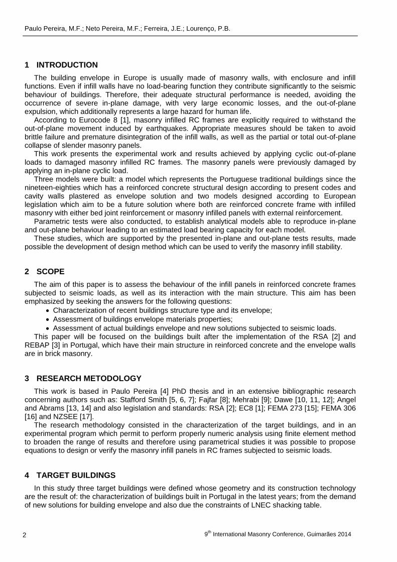
The three target buildings have been developed with a plan area of 5.70x6.45 m2 and a height equivalent to two floors with three meters each. The structure is composed by 0.18 m thickness solid concrete slabs which are supported by beams with cross section of 0.23x0.45 m2 which leads loads to six columns with cross section of 0.23x0.23 m2 which are supported by a strap beam with a cross section of 1.05x0.45 m2 (foundation will be assumed as an infinity rigid element).
Other variables were considered related the former design practices using RSA [2] and REBAP [3] and the actual design practice using the European legislation, namely the EC2 and the EC8 [1].
In order to build the prototypes it was used the Cauchy Similarity Law and Froude leading to a scaled reduction of the builds in a ratio of 1:1.5. As a result it was determined a plan geometry of 3.80x4.30 m2 and a height between floors of 2.00 m. Slabs have a thickness of 0.12 m, beams a cross section of 0.15x0.30 m2, columns a cross section of 0.15x0.15 m2 and the strap beam a cross section of 0.70x0.30 m2 (Figure 1 and Figure 2).
a) Foundation plan b) 1
st floor plan b) Roof plan
Figure 1. Prototypes geometric characterization
a) North elevation b) East elevation c) South elevation d) West elevation
Figure 2. Prototypes elevation geometric characterization
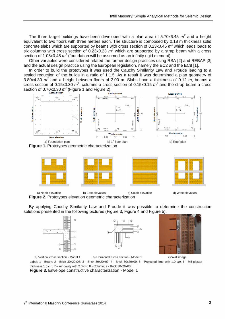
By applying Cauchy Similarity Law and Froude it was possible to determine the construction solutions presented in the following pictures (Figure 3, Figure 4 and Figure 5).
a) Vertical cross section - Model 1 b) Horizontal cross section - Model 1 c) Wall image
Label: 1 - Beam; 2 - Brick 30x20x03; 3 - Brick 30x20x07; 4 - Brick 30x20x09; 5 - Projected lime with 1.0 cm; 6 - M5 plaster –
thickness 1.0 cm; 7 – Air cavity with 2.0 cm; 8 - Column; 9 - Brick 30x20x03.
Figure 3. Envelope constructive characterization - Model 1
Paulo Pereira, M.F.; Neto Pereira, M.F.; Ferreira, J.E.; Lourenço, P.B.
9
th International Masonry Conference, Guimarães 2014 4
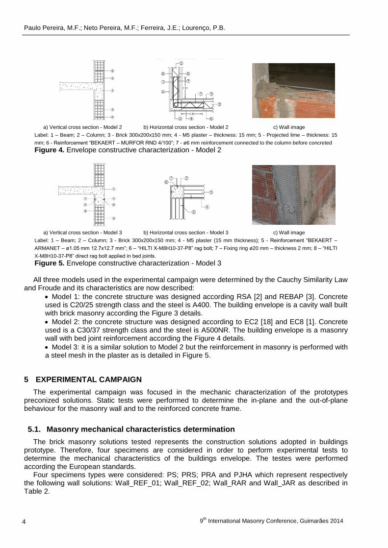
a) Vertical cross section - Model 2 b) Horizontal cross section - Model 2 c) Wall image
Label: 1 – Beam; 2 – Column; 3 - Brick 300x200x150 mm; 4 - M5 plaster – thickness: 15 mm; 5 - Projected lime – thickness: 15
mm; 6 - Reinforcement “BEKAERT – MURFOR RND 4/100”; 7 - ø6 mm reinforcement connected to the column before concreted
Figure 4. Envelope constructive characterization - Model 2
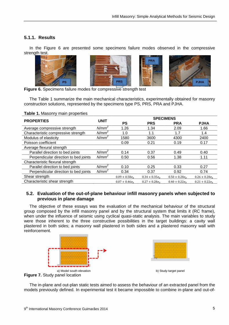
a) Vertical cross section - Model 3 b) Horizontal cross section - Model 3 c) Wall image
Label: 1 – Beam; 2 – Column; 3 - Brick 300x200x150 mm; 4 - M5 plaster (15 mm thickness); 5 - Reinforcement “BEKAERT –
ARMANET – ø1.05 mm 12.7x12.7 mm”; 6 – “HILTI X-M8H10-37-P8” rag bolt; 7 – Fixing ring ø20 mm – thickness 2 mm; 8 – “HILTI
X-M8H10-37-P8” direct rag bolt applied in bed joints.
Figure 5. Envelope constructive characterization - Model 3
All three models used in the experimental campaign were determined by the Cauchy Similarity Law
and Froude and its characteristics are now described:
Model 1: the concrete structure was designed according RSA [2] and REBAP [3]. Concrete used is C20/25 strength class and the steel is A400. The building envelope is a cavity wall built with brick masonry according the Figure 3 details.
Model 2: the concrete structure was designed according to EC2 [18] and EC8 [1]. Concrete used is a C30/37 strength class and the steel is A500NR. The building envelope is a masonry wall with bed joint reinforcement according the Figure 4 details.
Model 3: it is a similar solution to Model 2 but the reinforcement in masonry is performed with a steel mesh in the plaster as is detailed in Figure 5.
5 EXPERIMENTAL CAMPAIGN
The experimental campaign was focused in the mechanic characterization of the prototypes preconized solutions. Static tests were performed to determine the in-plane and the out-of-plane behaviour for the masonry wall and to the reinforced concrete frame.
5.1. Masonry mechanical characteristics determination
The brick masonry solutions tested represents the construction solutions adopted in buildings prototype. Therefore, four specimens are considered in order to perform experimental tests to determine the mechanical characteristics of the buildings envelope. The testes were performed according the European standards.
Four specimens types were considered: PS; PRS; PRA and PJHA which represent respectively the following wall solutions: Wall_REF_01; Wall_REF_02; Wall_RAR and Wall_JAR as described in Table 2.
Infill Masonry: Simple Analytical Methods for Seismic Design
9th
International Masonry Conference Guimarães 2014 5
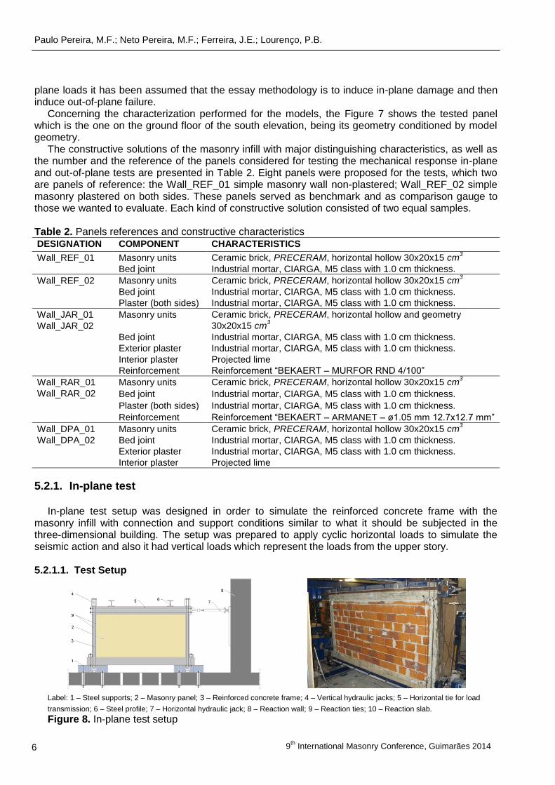
5.1.1. Results
In the Figure 6 are presented some specimens failure modes observed in the compressive strength test.
Figure 6. Specimens failure modes for compressive strength test
The Table 1 summarize the main mechanical characteristics, experimentally obtained for masonry
construction solutions, represented by the specimens type PS, PRS, PRA and PJHA.
Table 1. Masonry main properties
PROPERTIES UNIT SPECIMENS
PS PRS PRA PJHA
Average compressive strength N/mm2 1.26 1.34 2.09 1.66
Characteristic compressive strength N/mm2 1.0 1.1 1.7 1.4
Modulus of elasticity N/mm2 1580 3600 4300 2400
Poisson coefficient 0.09 0.21 0.19 0.17
Average flexural strength
Parallel direction to bed joints N/mm2 0.14 0.37 0.49 0.40
Perpendicular direction to bed joints N/mm2 0.50 0.56 1.38 1.11
Characteristic flexural strength
Parallel direction to bed joints N/mm2 0.10 0.25 0.33 0.27
Perpendicular direction to bed joints N/mm2 0.34 0.37 0.92 0.74
Shear strength
Characteristic shear strength
5.2. Evaluation of the out-of-plane behaviour infill masonry panels when subjected to previous in plane damage
The objective of these essays was the evaluation of the mechanical behaviour of the structural group composed by the infill masonry panel and by the structural system that limits it (RC frame), when under the influence of seismic using cyclical quasi-static analysis. The main variables to study were those inherent to the three constructive possibilities in the target buildings: a cavity wall plastered in both sides; a masonry wall plastered in both sides and a plastered masonry wall with reinforcement.
a) Model south elevation b) Study target panel
Figure 7. Study panel location The in-plane and out-plan static tests aimed to assess the behaviour of an extracted panel from the
models previously defined. In experimental test it became impossible to combine in-plane and out-of-
PS PRS
PS
PRA
PS
PJHAA
PS
Paulo Pereira, M.F.; Neto Pereira, M.F.; Ferreira, J.E.; Lourenço, P.B.
9
th International Masonry Conference, Guimarães 2014 6
plane loads it has been assumed that the essay methodology is to induce in-plane damage and then induce out-of-plane failure.
Concerning the characterization performed for the models, the Figure 7 shows the tested panel which is the one on the ground floor of the south elevation, being its geometry conditioned by model geometry.
The constructive solutions of the masonry infill with major distinguishing characteristics, as well as the number and the reference of the panels considered for testing the mechanical response in-plane and out-of-plane tests are presented in Table 2. Eight panels were proposed for the tests, which two are panels of reference: the Wall_REF_01 simple masonry wall non-plastered; Wall_REF_02 simple masonry plastered on both sides. These panels served as benchmark and as comparison gauge to those we wanted to evaluate. Each kind of constructive solution consisted of two equal samples.
Table 2. Panels references and constructive characteristics DESIGNATION COMPONENT CHARACTERISTICS
Wall_REF_01
Masonry units Ceramic brick, PRECERAM, horizontal hollow 30x20x15 cm3
Bed joint Industrial mortar, CIARGA, M5 class with 1.0 cm thickness.
Wall_REF_02
Masonry units Ceramic brick, PRECERAM, horizontal hollow 30x20x15 cm3
Bed joint Industrial mortar, CIARGA, M5 class with 1.0 cm thickness.
Plaster (both sides) Industrial mortar, CIARGA, M5 class with 1.0 cm thickness.
Wall_JAR_01
Wall_JAR_02
Masonry units Ceramic brick, PRECERAM, horizontal hollow and geometry
30x20x15 cm3
Bed joint Industrial mortar, CIARGA, M5 class with 1.0 cm thickness.
Exterior plaster Industrial mortar, CIARGA, M5 class with 1.0 cm thickness.
Interior plaster Projected lime
Reinforcement Reinforcement “BEKAERT – MURFOR RND 4/100”
Wall_RAR_01
Wall_RAR_02
Masonry units Ceramic brick, PRECERAM, horizontal hollow 30x20x15 cm3
Bed joint Industrial mortar, CIARGA, M5 class with 1.0 cm thickness.
Plaster (both sides) Industrial mortar, CIARGA, M5 class with 1.0 cm thickness.
Reinforcement Reinforcement “BEKAERT – ARMANET – ø1.05 mm 12.7x12.7 mm”
Wall_DPA_01
Wall_DPA_02
Masonry units Ceramic brick, PRECERAM, horizontal hollow 30x20x15 cm3
Bed joint Industrial mortar, CIARGA, M5 class with 1.0 cm thickness.
Exterior plaster Industrial mortar, CIARGA, M5 class with 1.0 cm thickness.
Interior plaster Projected lime
5.2.1. In-plane test
In-plane test setup was designed in order to simulate the reinforced concrete frame with the masonry infill with connection and support conditions similar to what it should be subjected in the three-dimensional building. The setup was prepared to apply cyclic horizontal loads to simulate the seismic action and also it had vertical loads which represent the loads from the upper story. 5.2.1.1. Test Setup
Label: 1 – Steel supports; 2 – Masonry panel; 3 – Reinforced concrete frame; 4 – Vertical hydraulic jacks; 5 – Horizontal tie for load
transmission; 6 – Steel profile; 7 – Horizontal hydraulic jack; 8 – Reaction wall; 9 – Reaction ties; 10 – Reaction slab.
Figure 8. In-plane test setup
Infill Masonry: Simple Analytical Methods for Seismic Design
9th
International Masonry Conference Guimarães 2014 7
The test setup was compounded by the following elements: lower fixing system; horizontal hydraulic jack with ties to permit to apply loads in a cyclic way; two vertical loads on the columns, to simulate the presence of the upper storeys. In-plane test set up is generically presented in Figure 8. The in-plane test is performed by applying cyclic horizontal displacements to the masonry panel until it reaches a predetermined value (0.5% drift). For each step, 3 load cycles were applied (load and unload) with the following drift ratio: 0.05%; 0.10%; 0.20%; 0.30%; 0.40%; 0.50%. 5.2.1.2. Results
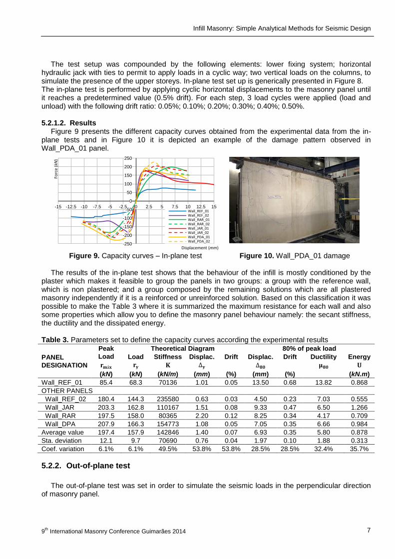
Figure 9 presents the different capacity curves obtained from the experimental data from the in-plane tests and in Figure 10 it is depicted an example of the damage pattern observed in Wall_PDA_01 panel.
Figure 9. Capacity curves – In-plane test Figure 10. Wall_PDA_01 damage
The results of the in-plane test shows that the behaviour of the infill is mostly conditioned by the
plaster which makes it feasible to group the panels in two groups: a group with the reference wall, which is non plastered; and a group composed by the remaining solutions which are all plastered masonry independently if it is a reinforced or unreinforced solution. Based on this classification it was possible to make the Table 3 where it is summarized the maximum resistance for each wall and also some properties which allow you to define the masonry panel behaviour namely: the secant stiffness, the ductility and the dissipated energy. Table 3. Parameters set to define the capacity curves according the experimental results
PANEL
DESIGNATION
Peak
Load
Theoretical Diagram 80% of peak load
Load Stiffness Displac. Drift Displac. Drift Ductility Energy
(kN) (kN) (kN/m) (mm) (%) (mm) (%) (kN.m)
Wall_REF_01 85.4 68.3 70136 1.01 0.05 13.50 0.68 13.82 0.868
OTHER PANELS
Wall_REF_02 180.4 144.3 235580 0.63 0.03 4.50 0.23 7.03 0.555
Wall_JAR 203.3 162.8 110167 1.51 0.08 9.33 0.47 6.50 1.266
Wall_RAR 197.5 158.0 80365 2.20 0.12 8.25 0.34 4.17 0.709
Wall_DPA 207.9 166.3 154773 1.08 0.05 7.05 0.35 6.66 0.984
Average value 197.4 157.9 142846 1.40 0.07 6.93 0.35 5.80 0.878
Sta. deviation 12.1 9.7 70690 0.76 0.04 1.97 0.10 1.88 0.313
Coef. variation 6.1% 6.1% 49.5% 53.8% 53.8% 28.5% 28.5% 32.4% 35.7%
5.2.2. Out-of-plane test
The out-of-plane test was set in order to simulate the seismic loads in the perpendicular direction of masonry panel.
-250
-200
-150
-100
-50
0
50
100
150
200
250
-15 -12.5 -10 -7.5 -5 -2.5 0 2.5 5 7.5 10 12.5 15
Forc
e (kN
)
Displacement (mm)
Wall_REF_01 Wall_REF_02 Wall_RAR_01 Wall_RAR_02 Wall_JAR_01 Wall_JAR_02 Wall_PDA_01 Wall_PDA_02
Paulo Pereira, M.F.; Neto Pereira, M.F.; Ferreira, J.E.; Lourenço, P.B.
9
th International Masonry Conference, Guimarães 2014 8
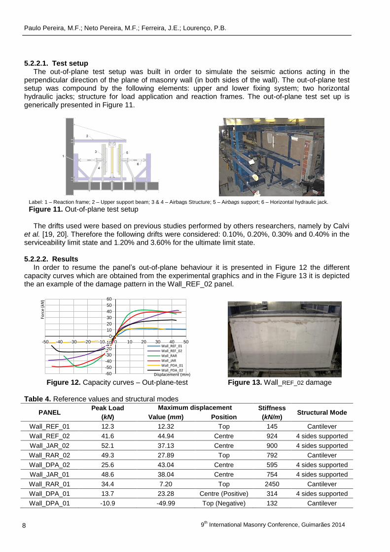
5.2.2.1. Test setup The out-of-plane test setup was built in order to simulate the seismic actions acting in the
perpendicular direction of the plane of masonry wall (in both sides of the wall). The out-of-plane test setup was compound by the following elements: upper and lower fixing system; two horizontal hydraulic jacks; structure for load application and reaction frames. The out-of-plane test set up is generically presented in Figure 11.
Label: 1 – Reaction frame; 2 – Upper support beam; 3 & 4 – Airbags Structure; 5 – Airbags support; 6 – Horizontal hydraulic jack.
Figure 11. Out-of-plane test setup
The drifts used were based on previous studies performed by others researchers, namely by Calvi
et al. [19, 20]. Therefore the following drifts were considered: 0.10%, 0.20%, 0.30% and 0.40% in the serviceability limit state and 1.20% and 3.60% for the ultimate limit state. 5.2.2.2. Results
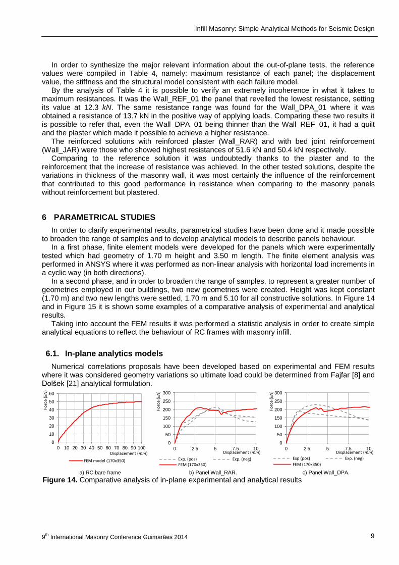
In order to resume the panel’s out-of-plane behaviour it is presented in Figure 12 the different capacity curves which are obtained from the experimental graphics and in the Figure 13 it is depicted the an example of the damage pattern in the Wall_REF_02 panel.
Figure 12. Capacity curves – Out-plane-test Figure 13. Wall_REF_02 damage
Table 4. Reference values and structural modes
PANEL Peak Load Maximum displacement Stiffness
Structural Mode (kN) Value (mm) Position (kN/m)
Wall_REF_01 12.3 12.32 Top 145 Cantilever
Wall_REF_02 41.6 44.94 Centre 924 4 sides supported
Wall_JAR_02 52.1 37.13 Centre 900 4 sides supported
Wall_RAR_02 49.3 27.89 Top 792 Cantilever
Wall_DPA_02 25.6 43.04 Centre 595 4 sides supported
Wall_JAR_01 48.6 38.04 Centre 754 4 sides supported
Wall_RAR_01 34.4 7.20 Top 2450 Cantilever
Wall_DPA_01 13.7 23.28 Centre (Positive) 314 4 sides supported
Wall_DPA_01 -10.9 -49.99 Top (Negative) 132 Cantilever
-60
-50
-40
-30
-20
-10
0
10
20
30
40
50
60
-50 -40 -30 -20 -10 0 10 20 30 40 50
Forc
e (kN
)
Displacement (mm)
Wall_REF_01 Wall_REF_02 Wall_RAR Wall_JAR Wall_PDA_01 Wall_PDA_02
Infill Masonry: Simple Analytical Methods for Seismic Design
9th
International Masonry Conference Guimarães 2014 9
In order to synthesize the major relevant information about the out-of-plane tests, the reference values were compiled in Table 4, namely: maximum resistance of each panel; the displacement value, the stiffness and the structural model consistent with each failure model.
By the analysis of Table 4 it is possible to verify an extremely incoherence in what it takes to maximum resistances. It was the Wall_REF_01 the panel that revelled the lowest resistance, setting its value at 12.3 kN. The same resistance range was found for the Wall_DPA_01 where it was obtained a resistance of 13.7 kN in the positive way of applying loads. Comparing these two results it is possible to refer that, even the Wall_DPA_01 being thinner than the Wall_REF_01, it had a quilt and the plaster which made it possible to achieve a higher resistance.
The reinforced solutions with reinforced plaster (Wall_RAR) and with bed joint reinforcement (Wall_JAR) were those who showed highest resistances of 51.6 kN and 50.4 kN respectively.
Comparing to the reference solution it was undoubtedly thanks to the plaster and to the reinforcement that the increase of resistance was achieved. In the other tested solutions, despite the variations in thickness of the masonry wall, it was most certainly the influence of the reinforcement that contributed to this good performance in resistance when comparing to the masonry panels without reinforcement but plastered.
6 PARAMETRICAL STUDIES
In order to clarify experimental results, parametrical studies have been done and it made possible to broaden the range of samples and to develop analytical models to describe panels behaviour.
In a first phase, finite element models were developed for the panels which were experimentally tested which had geometry of 1.70 m height and 3.50 m length. The finite element analysis was performed in ANSYS where it was performed as non-linear analysis with horizontal load increments in a cyclic way (in both directions).
In a second phase, and in order to broaden the range of samples, to represent a greater number of geometries employed in our buildings, two new geometries were created. Height was kept constant (1.70 m) and two new lengths were settled, 1.70 m and 5.10 for all constructive solutions. In Figure 14 and in Figure 15 it is shown some examples of a comparative analysis of experimental and analytical results.
Taking into account the FEM results it was performed a statistic analysis in order to create simple analytical equations to reflect the behaviour of RC frames with masonry infill.
6.1. In-plane analytics models
Numerical correlations proposals have been developed based on experimental and FEM results where it was considered geometry variations so ultimate load could be determined from Fajfar [8] and Dolšek [21] analytical formulation.
a) RC bare frame b) Panel Wall_RAR. c) Panel Wall_DPA.
Figure 14. Comparative analysis of in-plane experimental and analytical results
0
10
20
30
40
50
60
0 10 20 30 40 50 60 70 80 90 100
Forc
e (kN
)
Displacement (mm)
FEM model (170x350)
0
50
100
150
200
250
300
0 2.5 5 7.5 10
Forc
e (kN
)
Displacement (mm)
Exp. (pos) Exp. (neg) FEM (170x350)
0
50
100
150
200
250
300
0 2.5 5 7.5 10
Forc
e (kN
)
Displacement (mm)
Exp (pos) Exp. (neg)
FEM (170x350)
Paulo Pereira, M.F.; Neto Pereira, M.F.; Ferreira, J.E.; Lourenço, P.B.
9
th International Masonry Conference, Guimarães 2014 10
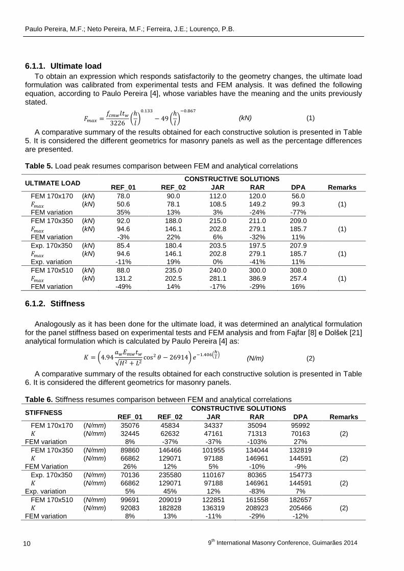
6.1.1. Ultimate load
To obtain an expression which responds satisfactorily to the geometry changes, the ultimate load formulation was calibrated from experimental tests and FEM analysis. It was defined the following equation, according to Paulo Pereira [4], whose variables have the meaning and the units previously stated.
(kN) (1)
A comparative summary of the results obtained for each constructive solution is presented in Table 5. It is considered the different geometrics for masonry panels as well as the percentage differences are presented.
Table 5. Load peak resumes comparison between FEM and analytical correlations
ULTIMATE LOAD CONSTRUCTIVE SOLUTIONS
REF_01 REF_02 JAR RAR DPA Remarks
FEM 170x170 (kN) 78.0 90.0 112.0 120.0 56.0
(kN) 50.6 78.1 108.5 149.2 99.3 (1)
FEM variation 35% 13% 3% -24% -77%
FEM 170x350 (kN) 92.0 188.0 215.0 211.0 209.0
(kN) 94.6 146.1 202.8 279.1 185.7 (1)
FEM variation -3% 22% 6% -32% 11%
Exp. 170x350 (kN) 85.4 180.4 203.5 197.5 207.9
(kN) 94.6 146.1 202.8 279.1 185.7 (1)
Exp. variation -11% 19% 0% -41% 11%
FEM 170x510 (kN) 88.0 235.0 240.0 300.0 308.0
(kN) 131.2 202.5 281.1 386.9 257.4 (1)
FEM variation -49% 14% -17% -29% 16%
6.1.2. Stiffness
Analogously as it has been done for the ultimate load, it was determined an analytical formulation for the panel stiffness based on experimental tests and FEM analysis and from Fajfar [8] e Dolšek [21] analytical formulation which is calculated by Paulo Pereira [4] as:
(N/m) (2)
A comparative summary of the results obtained for each constructive solution is presented in Table 6. It is considered the different geometrics for masonry panels. Table 6. Stiffness resumes comparison between FEM and analytical correlations
STIFFNESS CONSTRUCTIVE SOLUTIONS
REF_01 REF_02 JAR RAR DPA Remarks
FEM 170x170 (N/mm) 35076 45834 34337 35094 95992
(N/mm) 32445 62632 47161 71313 70163 (2)
FEM variation 8% -37% -37% -103% 27%
FEM 170x350 (N/mm) 89860 146466 101955 134044 132819
(N/mm) 66862 129071 97188 146961 144591 (2)
FEM Variation 26% 12% 5% -10% -9%
Exp. 170x350 (N/mm) 70136 235580 110167 80365 154773
(N/mm) 66862 129071 97188 146961 144591 (2)
Exp. variation 5% 45% 12% -83% 7%
FEM 170x510 (N/mm) 99691 209019 122851 161558 182657
(N/mm) 92083 182828 136319 208923 205466 (2)
FEM variation 8% 13% -11% -29% -12%
Infill Masonry: Simple Analytical Methods for Seismic Design
9th
International Masonry Conference Guimarães 2014 11
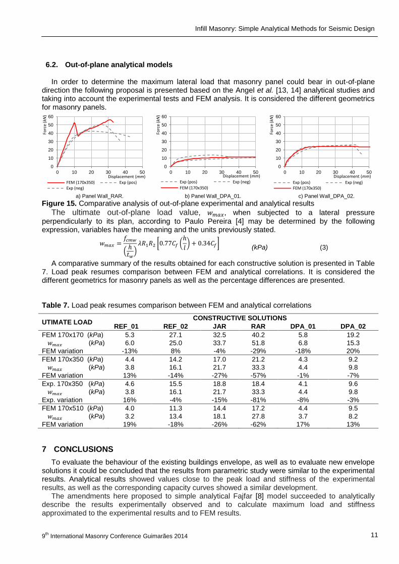
6.2. Out-of-plane analytical models In order to determine the maximum lateral load that masonry panel could bear in out-of-plane
direction the following proposal is presented based on the Angel et al. [13, 14] analytical studies and taking into account the experimental tests and FEM analysis. It is considered the different geometrics for masonry panels.
a) Panel Wall_RAR. b) Panel Wall_DPA_01. c) Panel Wall_DPA_02.
Figure 15. Comparative analysis of out-of-plane experimental and analytical results
The ultimate out-of-plane load value, , when subjected to a lateral pressure
perpendicularly to its plan, according to Paulo Pereira [4] may be determined by the following expression, variables have the meaning and the units previously stated.
(kPa) (3)
A comparative summary of the results obtained for each constructive solution is presented in Table 7. Load peak resumes comparison between FEM and analytical correlations. It is considered the different geometrics for masonry panels as well as the percentage differences are presented.
Table 7. Load peak resumes comparison between FEM and analytical correlations
UTIMATE LOAD CONSTRUCTIVE SOLUTIONS
REF_01 REF_02 JAR RAR DPA_01 DPA_02
FEM 170x170 (kPa) 5.3 27.1 32.5 40.2 5.8 19.2
(kPa) 6.0 25.0 33.7 51.8 6.8 15.3
FEM variation -13% 8% -4% -29% -18% 20%
FEM 170x350 (kPa) 4.4 14.2 17.0 21.2 4.3 9.2
(kPa) 3.8 16.1 21.7 33.3 4.4 9.8
FEM variation 13% -14% -27% -57% -1% -7%
Exp. 170x350 (kPa) 4.6 15.5 18.8 18.4 4.1 9.6
(kPa) 3.8 16.1 21.7 33.3 4.4 9.8
Exp. variation 16% -4% -15% -81% -8% -3%
FEM 170x510 (kPa) 4.0 11.3 14.4 17.2 4.4 9.5
(kPa) 3.2 13.4 18.1 27.8 3.7 8.2
FEM variation 19% -18% -26% -62% 17% 13%
7 CONCLUSIONS
To evaluate the behaviour of the existing buildings envelope, as well as to evaluate new envelope solutions it could be concluded that the results from parametric study were similar to the experimental results. Analytical results showed values close to the peak load and stiffness of the experimental results, as well as the corresponding capacity curves showed a similar development.
The amendments here proposed to simple analytical Fajfar [8] model succeeded to analytically describe the results experimentally observed and to calculate maximum load and stiffness approximated to the experimental results and to FEM results.
0
10
20
30
40
50
60
0 10 20 30 40 50
Forc
e (kN
)
Displacement (mm) FEM (170x350) Exp (pos) Exp (neg)
0
10
20
30
40
50
60
0 10 20 30 40 50
Forc
e (kN
)
Displacement (mm)
Exp (pos) Exp (neg)
FEM (170x350)
0
10
20
30
40
50
60
0 10 20 30 40 50
Forc
e (kN
)
Displacement (mm)
Exp (pos) Exp (neg) FEM (170x350)
Paulo Pereira, M.F.; Neto Pereira, M.F.; Ferreira, J.E.; Lourenço, P.B.
9
th International Masonry Conference, Guimarães 2014 12
The simple analytical model adapted from Angel [13, 14] with the alteration proposed in this paper make it possible to calculate out-of-plane maximum load with values approximated to the experimental results and to FEM results.
REFERENCES [1] IPQ, NP EN 1998-1-1:2010, Eurocódigo 8 - Projecto de estruturas para resistência aos sismos.
Parte 1: Regras gerais, acções sísmicas e regras para edifícios, 2010.
[2] RSA, Regulamento de segurança e acções para estruturas de edifícios e pontes, 1983.
[3] REBAP, Regulamento de estruturas de betão armado e pré-esforçado, 1983.
[4] Paulo Pereira, M. F., “Avaliação do desempenho das envolventes dos edifícios face à acção dos sismos”, Universidade do Minho, Guimarães, Portugal, 2013
[5] Stafford Smith, B., "Model test results of vertical and horizontal loading of infilled frames", ACI journal, Vol. 65, August 1968.
[6] Stafford Smith, B. e Coull, A., Tall building structures: Analysis and design, Wiley, New York, 1991.
[7] Stafford Smith, B. e Carter, C., "A method of analysis for infilled frames", Proceedings of the Institution of Civil Engineers, Vol. 44, pp. 31-44, 1969.
[8] Fajfar, P. e Eeri, M., "A nonlinear analysis method for performance based seismic design", Earthquake Spectra, Vol. 16, pp. 573-592, 2000.
[9] Mehrabi, A. B., et al., "Performance of masonry-infilled R/C frames under in-plane lateral loads", University of Colorado at Boulder, 1994.
[10] Dawe, J. L. e Seah, C. K., "Out-of-plane resistance of concrete masonry infilled panels", Journal of the Canadian Society of Civil Engineering, Vol. 16, pp. 854-864, 1989.
[11] Dawe, J. L., et al., "Masonry infilled steel frames subjected to dynamic load", Department of Civil Engineering, University of New Brunswick, Fredericton, N.B., Canada, 1989.
[12] Dawe, J. L. e Seah, C. K., "Lateral load resistance of masonry panels in flexible steel frames", Proceedings of the Eighth International Brick and Block Masonry Conference, Trinity College, Dublin, Ireland, 1988.
[13] Angel, R., et al., "Behaviour of reinforced concrete frames with masonry infills", Department of Civil Engineering, University of Illinois, USA, UILU-ENG-94-2005, 1994.
[14] Angel, R. e Abrams, D. P., "Out-of-plane strength evaluation of URM infill panels", Proceedings of the NCEER Workshop on Seismic Response of Masonry Infills, 1994.
[15] FEMA 273, NEHRP - Guidelines for the seismic rehabilitation of buildings, 1997.
[16] FEMA 306, Evaluation of earthquake damaged concrete and masonry wall buildings, 1998.
[17] NZSEE, "Assessment and improvement of the structural performance of buildings in earthquakes", 2006.
[18] IPQ, NP EN 1992-1-1:2010, Eurocódigo 2 - Projecto de estruturas de betão. Parte 1-1: Regras gerais e regras para edifícios, 2010.
[19] Calvi, G. M., et al., "Seismic performance of masonry-infilled RC frames: Benefits of slight reinforcements", Sísmica 2004 - 6º Congresso Nacional de Sismologia e Engenharia Sísmica, Lisboa, 2004.
[20] [66] Calvi, G. M., et al., "Design of masonry structures with bed joint reinforcement", Seminário sobre paredes de alvenaria, Lisboa, 2007.
[21] Dolšek, M. e Fajfar, P., "Mathematical modelling of an inlled RC frame structure based on the results of pseudo-dynamic tests", Earthquake Engineering & Structural Dynamics, Vol. 31, pp. 1215-1230, 2002.
Related Documents